UV Detectors Fixed Wavelength Variable Wavelength Diode array.

Advanced Features of InfraTec Pyroeletric Detectors
1 0BBasics and Application of Variable Color Products
The key element of InfraTec’s variable color products is a silicon micro machined tunable narrow bandpass filter, which is fully integrated inside the detector housing. Applying a control voltage to the filter allows it to freely select the wavelength within a certain spectral range or to sequentially measure a continuous spec-trum. This design is very different from detectors with fixed filter characteristics and enables the customer to realize a low resolving and low cost spectrometer. The variable color product group currently includes the LFP-3041L-337
LFP-3950L-337
LFP-80105-337
which differ in the wavelength range they each cover. The pyroelectric detector used is similar to the stand-ard LME-335 device, but with a shorter electrical time constant. New types and wavelength ranges may be introduced in the future.
1.1 1BFabry-Pérot filter (FPF)
The tunable filter is based on the well-known Fabry-Pérot Interferometer (FPI). Two flat and partially trans-mitting mirrors, characterized by reflectance R and absorptance A, are arranged in parallel at a distance d, forming an optical resonator with the refractive index n (figure 20 left). The beam with intensity I0, incident under the angle β, is reflected back and forth inside the resonator. Multi-
ple-beam interference generates a pattern of successive peaks in the transmittance spectrum T() of the FPF (figure 20 right), described by the Airy formula
cosπ2sin1 2
max
0 dnF
T
I
IT t
(6)
with the peak transmittance
2
max 11
R
AT (7)
and the finesse factor
214
R
RF
(8)

Advanced Features of InfraTec Pyroeletric Detectors
Fig 1: Schematic configuration and transmittance function of the Fabry-Pérot Interferometer
The transmittance peaks of different interference orders m are located at wavelengths, for which the reso-nance condition
m
dnm
cos2 (9)
is met. The FPI can be used as a tunable narrowband filter, if the desired order is selected by means of an additional broad bandpass filter (order sorting filter, blocking filter) and if the resonator gap d can be adjusted to tune the transmitted wavelength λm within the given free spectral range FSR for this order. The character-istic filter parameters of an FPF can be derived from the previous equations. In all types, that are currently available from InfraTec, the first interference order is used (m = 1). Given that n = 1 (air inside the gap) and β = 0 (normal incidence), the equations can be further simplified. The center wavelength CWL is defined as the mean value of the two half-power-points (T50) in terms of wavenumbers:
21
212
CWL (10)
(Because of the periodicity of the Airy formula (eq. 6) in wavenumbers, calculation of the CWL in the wave-number domain is preferred over wavelengths. In general, calculation of the CWL of interference filters in the wavenumber or wavelength domain are both common). The half-power bandwidth HPBW is the decisive factor for the spectral resolution:
R
RdHPBWπ12
(11)
The ratio of FSR and HPBW (calculated in terms of wavenumbers) is called the finesse F~ . In the theoretical ideal case (perfectly flat, smooth and parallel mirrors, collimated beam) it depends only
on the reflectance R (reflectance finesse RF~ )
2π
1π~ F
R
R
HPBW
FSRFR
(12)
In practice the finesse is limited by imperfections of the mirrors and the angle distribution of the transmitted beam.

Advanced Features of InfraTec Pyroeletric Detectors
1.2 2BVariable Color detector
InfraTec’s FP filters are fabricated with silicon bulk micromachining technology and wafer bonding. Bragg reflectors for the specific wavelength ranges are coated on thick silicon carriers to guarantee a high finesse. The back sides are anti-reflection coated. The fixed bottom carrier is equipped with control electrodes, whereas the upper reflector is suspended by springs (figure 21). Applying a voltage Vc to the electrodes cre-ates an electrostatic force, which decreases the resonator gap d and, consequently, tunes the filter wave-length.
Fig 2: Schematic configuration (left) and picture (right) of the variable color detector
The MOEMS FPF is integrated in a TO8 housing together with a pyroelectric detector (figure 21). The latter is a state of the art thermally compensated current-mode type, similar to LME-335 but with smaller feedback capacitance. This results in a flat frequency response up to several tens of Hz. The thermal time constant is in the range of 150 ms. The element size of (2 x 2) mm2 matches the size of the filter aperture (Ø 1.9 mm). The broad band pass blocking filter is integrated in the cap. The mirrors of the FPI are made from dielectric layer stacks (Bragg reflectors) with a limited width of the re-flective band (stop band). Therefore, the usable tuning range in the first order is less than expected from the theoretical FSR. Besides this, the reflectance and, consequently, the finesse vary over the tuning range
( RF~ ≈ 40…80). Tuning the CWL therefore results in a variation of the HPBW and the peak transmittance
within certain limits. Figure 22 shows the typical variation of the HPBW and the limits given by fabrication tolerances. HPBWmin corresponds to the center and HPBWmax to the upper end of the tuning range.
Filter code HPBWmin HPBWmax Tolerance range
3041L 68 nm 85 nm +85 … 95 nm -55 … 70 nm
3950L 75 nm 93 nm +90 … 110 nm
-65 … 80 nm
80105 130 nm 220 nm +170 … 270 nm -100 … 180 nm
Fig 3: HPBW over tuning range, typical values and tolerance range. left: curves for LFP-3041L-337;

Advanced Features of InfraTec Pyroeletric Detectors
right: table for the currently existing filter types (measured with FTIR, ±6°, 4 cm-1)
The broad band pass and the pyroelectric detector element also show some spectral characteristics. The spectral response of the detector is a superposition of different fractions, but has to be considered as a whole in the application. At InfraTec, calibration measurements (figure 23) are performed by means of an FTIR spectrometer. The spectra are referenced to a ‘black’ detector with a flat spectral response and normal-ized to the highest peak (relative spectral response).
4006 nm65 nm
19.71 V
3800 nm63 nm
23.38 V
3596 nm62 nm
25.96 V
3400 nm59 nm
27.79 V
3206 nm59 nm
29.15 V
3000 nm66 nm
30.22 V
0
0.2
0.4
0.6
0.8
1
2.6 3 3.4 3.8 4.2 4.6
rela
tvie
sp
ectr
al r
esp
on
se
λ [µm]
CWL = 4381 nmHPBW = 80 nm
Vc = 00.00 V
4198 nm70 nm
14.40 V
Fig 4: Relative spectral response of a FPF detector LFP-3041L-337 at several tuning voltages
1.3 3BOptical Considerations
The basic theory described in section 4.1 is restricted to simplified conditions, which requires a normal inci-dent and perfectly collimated beam. An inclined but collimated beam results in a negative drift of the CWL (figure 24 left), but the most common case is an uncollimated beam with a certain angle of divergence and intensity profile. The resulting transmittance spectrum can be seen as the superposition of collimated ray-beams with different angles of incidence and intensities. The superimposed spectrum has a broader HPBW and the CWL at slightly lower wavelengths (figure 24 right).
Fig 5: Influence of angle shift and divergence angle on bandwidth and peak transmittance of a FPF

Advanced Features of InfraTec Pyroeletric Detectors
This effect is very well known from fixed interference filters but much more pronounced for FPF with a tuna-ble air gap. Figures 25 and 26 show theoretical and measured values of the angle shift, relative to the ideal case (collimated).
Fig 6: Relative shift of the CWL over the full cone angle, theoretical and measured with FTIR (mean angle of incidence 0°)
Fig 7: Relative shift of the HPBW over the full cone angle, measured with FTIR (mean angle of incidence 0°)
Wavelength shift depends only on the intensity distribution within the cone angle but not on the finesse. The thick curve (figure 25) may be considered as the worst case: a source with a lambertian intensity distribution. In practice higher angles often carry less intensity, which seems to be case in the FTIR measurement shown through the dashed curve. In contrast to the wavelength shift, the broadening effect depends on intensity distribution and the finesse (reflectance and surface defects of the mirrors). A higher finesse results in a stronger broadening (figure 26 upper limit) and vice versa. In the discussion above, normal incidence was considered. It is important to note, that illumination with an oblique (mean) and convergent (or divergent) ray bundle shift effects become even stronger and the spectra may be distorted dramatically. Angle shift results in very important conclusions for the design and operation of FPF based analyzers or microspectrometers: The spectral performance of an instrument strongly depends on the optical conditions. As a conse-
quence, the calibration of an FPF based instrument (wavelength and resolution) should be carried out
within the final optical setup.
For each particular application a compromise between spectral resolution and signal-to-noise ratio SNR
(throughput) needs to be found. This is a principal rule, which is valid for all kinds of spectrometers.
Beam divergence can be minimized by using a light source with collimated output or by means of an addi-tional prefixed aperture (figure 27 left). If the goal is to maximize the optical throughput, then focusing optics can be used, but larger cone angles will be a side effect (figure 27 right).

Advanced Features of InfraTec Pyroeletric Detectors
High Resolution High SNR
7B
FP-Detector
Aperture
IR-sourcecollimated output
Sample cell
FP-DetectorFocusing optic
IR-sourceSample cell
Fig 8: Possible optimizations for the optical design of a microspectrometer with FPF detector left: illumination with a parallel beam; right: illumination with a large cone angle
Figure 28 shows the correlation of the achievable SNR with a given spectral resolution, measured with two tested measurement set ups according to figure 27. Please note that a parallel beam ø1 mm offers the high-est spectral resolution but only 3 % of the intensity and thus the resulting low detector signal voltage com-pared to an illumination using f/1.4 optics.
100
1.000
10.000
40 50 60 70 80
SN
R
R = λ/∆λ
„High SNR“f/1.4 optics
„High Resolution“parallel beam Ø1mm
Fig 9: Measurements of the SNR vs. spectral resolution (LFP-3041L-337, modulated IR source at 10 Hz); left end point: Illumination with a large cone angle using f/1.4 optics right end point: Illumination with a parallel beam ø 1 mm
Advanced Features of InfraTec Pyroeletric Detectors
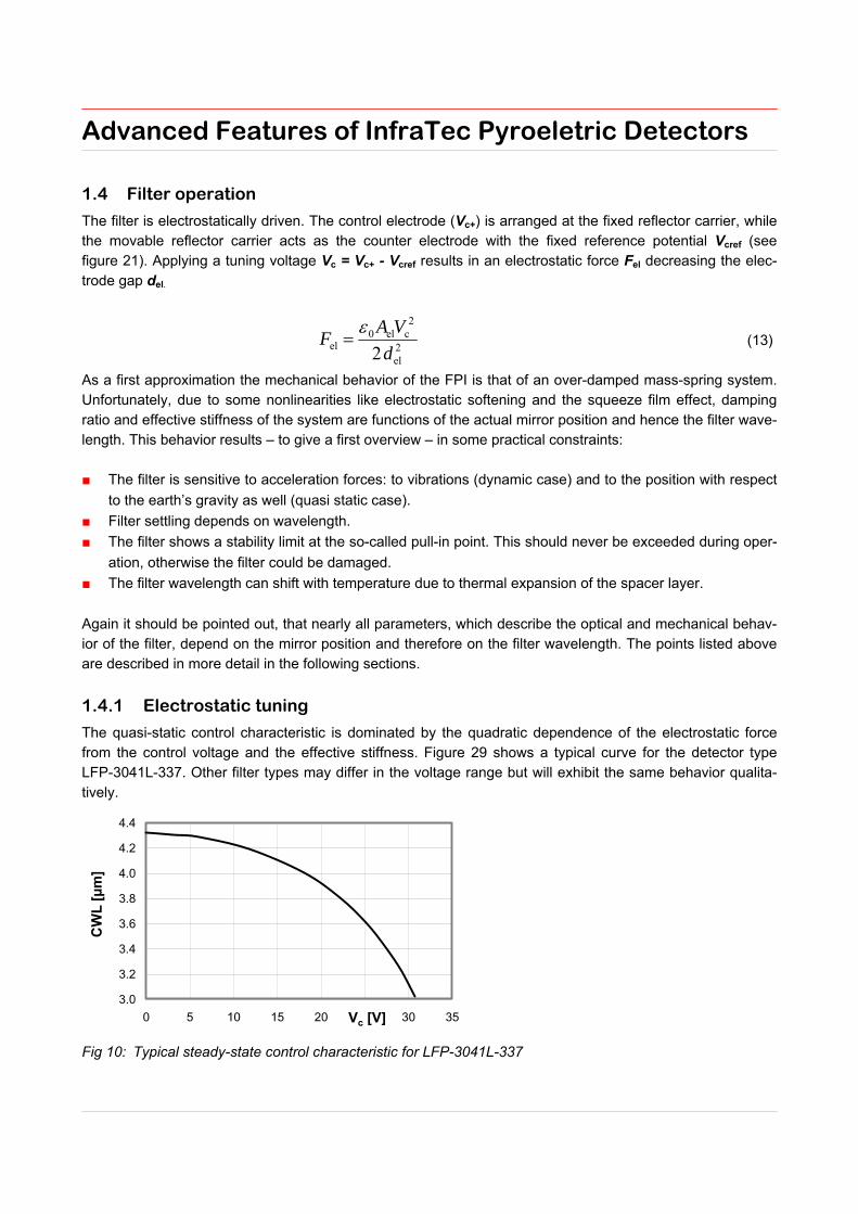
1.4 4BFilter operation
The filter is electrostatically driven. The control electrode (Vc+) is arranged at the fixed reflector carrier, while the movable reflector carrier acts as the counter electrode with the fixed reference potential Vcref (see figure 21). Applying a tuning voltage Vc = Vc+ - Vcref results in an electrostatic force Fel decreasing the elec-trode gap del.
2el
2cel0
el 2d
VAF
(13)
As a first approximation the mechanical behavior of the FPI is that of an over-damped mass-spring system. Unfortunately, due to some nonlinearities like electrostatic softening and the squeeze film effect, damping ratio and effective stiffness of the system are functions of the actual mirror position and hence the filter wave-length. This behavior results – to give a first overview – in some practical constraints: The filter is sensitive to acceleration forces: to vibrations (dynamic case) and to the position with respect
to the earth’s gravity as well (quasi static case).
Filter settling depends on wavelength.
The filter shows a stability limit at the so-called pull-in point. This should never be exceeded during oper-
ation, otherwise the filter could be damaged.
The filter wavelength can shift with temperature due to thermal expansion of the spacer layer.
Again it should be pointed out, that nearly all parameters, which describe the optical and mechanical behav-ior of the filter, depend on the mirror position and therefore on the filter wavelength. The points listed above are described in more detail in the following sections.
1.4.1 8BElectrostatic tuning
The quasi-static control characteristic is dominated by the quadratic dependence of the electrostatic force from the control voltage and the effective stiffness. Figure 29 shows a typical curve for the detector type LFP-3041L-337. Other filter types may differ in the voltage range but will exhibit the same behavior qualita-tively.
Fig 10: Typical steady-state control characteristic for LFP-3041L-337
Advanced Features of InfraTec Pyroeletric Detectors
By analyzing equation (13) a positive feedback of del to the electrostatic force Fel becomes evident (electro-static softening). The maximum stable operation range of a voltage controlled electrostatic actuator is there-fore limited by the so called pull-in instability.
The pull-in voltage should never be exceeded; otherwise the device may suffer irreparable damage. In
practice this means: For each individual device (FPF) exists a maximum allowable control voltage for
save and stable operation. Because of the fabrication tolerances, no general document like datasheets
or application notes can provide this information to the user. One can obtain this from the individual
measurement report only.
Furthermore, the polarity of the control voltage needs to be maintained, even as in equation (13) this does not seem to be necessary.
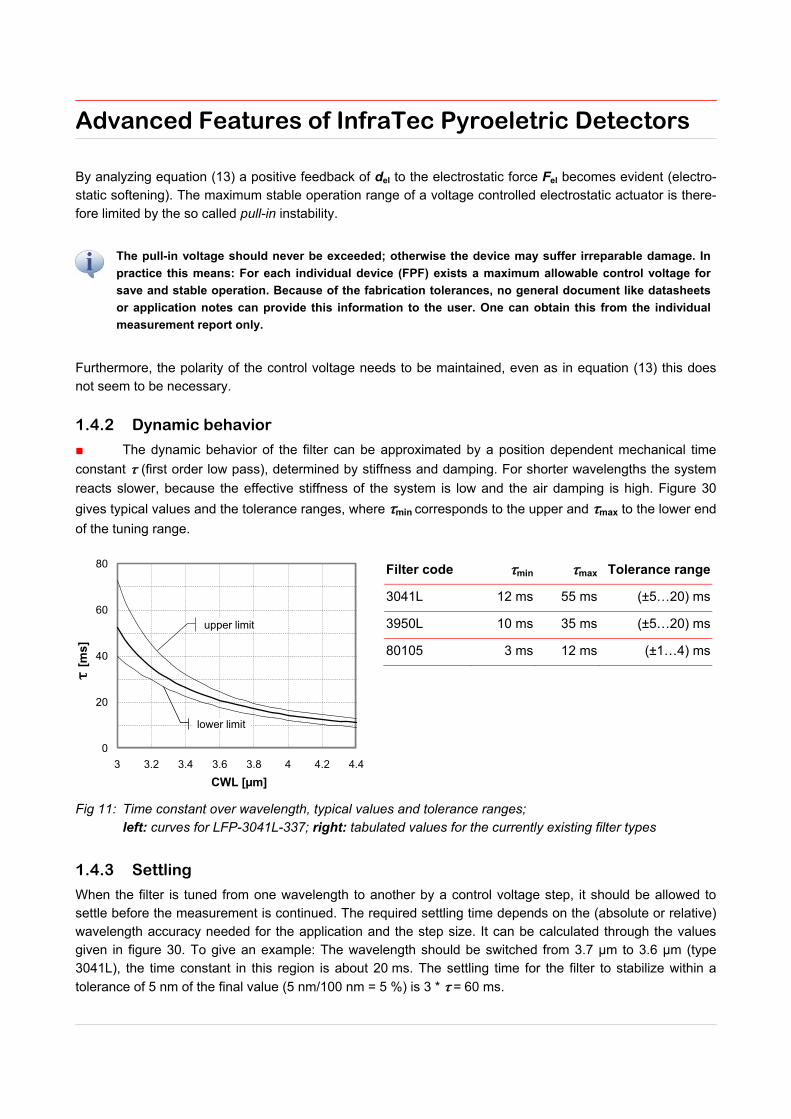
1.4.2 9BDynamic behavior
The dynamic behavior of the filter can be approximated by a position dependent mechanical time
constant τ (first order low pass), determined by stiffness and damping. For shorter wavelengths the system
reacts slower, because the effective stiffness of the system is low and the air damping is high. Figure 30
gives typical values and the tolerance ranges, where τmin corresponds to the upper and τmax to the lower end
of the tuning range.
Filter code τmin τmax Tolerance range
3041L 12 ms 55 ms (±5…20) ms
3950L 10 ms 35 ms (±5…20) ms
80105 3 ms 12 ms (±1…4) ms
Fig 11: Time constant over wavelength, typical values and tolerance ranges; left: curves for LFP-3041L-337; right: tabulated values for the currently existing filter types
1.4.3 10BSettling
When the filter is tuned from one wavelength to another by a control voltage step, it should be allowed to settle before the measurement is continued. The required settling time depends on the (absolute or relative) wavelength accuracy needed for the application and the step size. It can be calculated through the values given in figure 30. To give an example: The wavelength should be switched from 3.7 µm to 3.6 µm (type 3041L), the time constant in this region is about 20 ms. The settling time for the filter to stabilize within a
tolerance of 5 nm of the final value (5 nm/100 nm = 5 %) is 3 * τ = 60 ms.

Advanced Features of InfraTec Pyroeletric Detectors
Unfortunately, for the practical use of an FPF with a pyroelectric detector this is only part of the truth. Switch-ing from one wavelength to another also causes a modulation of the radiation falling on the detector. In the worst case, a step over the entire tuning range, the detector ‘sees’ the complete spectrum (similar to the sweep mode, see section 4.5). Decisive for the settling of the detector output is the longest time constant in the system, which is the thermal time constant of the pyroelectric detector (in the range of 150 ms). How fast the ‘measured value’ settles, depends on the signal processing, too (bandwidth of software filtering, FFT/Lock-In). This subject is quite complicated and out of the scope of this application note.
1.4.4 11BAcceleration response
If the filter is exposed to acceleration forces, the upper reflector carrier will move and cause the filter
wavelength to shift. The quasi-static response, like turning the filter with respect to the earth’s gravity, de-
pends mainly on the effective stiffness and on the mass of the movable reflector. Figure 31 gives typical
values and tolerance ranges, where CWLmin corresponds to the upper and CWLmax to the lower end of the
tuning range.
Filter code ∆CWLmin ∆CWLmax Tolerance range
3041L 12.5 nm/g 36 nm/g (±2.5…6) nm/g
3950L 12.5 nm/g 32 nm/g (±2.5…5) nm/g
80105 25 nm/g 65 nm/g (±7…25) nm/g
Fig 12: Wavelength shift ∆CWL by gravity when turning the filter upside-down (± 1 g), typical values and tolerance ranges; left: curves for LFP-3041L-337; right: tabulated values for the currently existing filter types (1 g = 9.81 m/s²)
In addition, the filter responds to dynamic vibrational forces, too. Due to the squeeze film effect, high fre-quency vibrations (see figure 30 for the mechanical time constants) are effectively damped.
1.4.5 12BTemperature shift
Interference filters are generally prone to a temperature shift, which is partly caused by purely mechanical expansion of the dielectric thin films and partly by a change of the optical constants of the materials. In case of tunable FP filters, the temperature shift is dominated by thermal expansion of the spacer layer, which de-fines the width of the air gap. As a temperature change mainly results in a mechanical detuning of the gap, the correlation between HPBW and CWL remains unchanged. Again this effect is wavelength depended. At a given wavelength the temperature shift is nearly linear, and
therefore a temperature coefficient TCλ can be given. For shorter wavelengths the shift becomes larger, be-
cause of the reduced effective stiffness. Figure 32 gives typical values and tolerance ranges, where TCλ min
corresponds to the upper and TCλ max to the lower end of the tuning range.

Advanced Features of InfraTec Pyroeletric Detectors
Filter code TCλ min TCλ max Tolerance range
3041L 2.0 nm/K 4.0 nm/K (±0.2…0.5) nm/K
3950L 2.0 nm/K 3.8 nm/K (±0.2…0.5) nm/K
80105 2.0 nm/K 3.2 nm/K (±0.5…1.0) nm/K
Fig 13: Temperature coefficient of the CWL, typical values and tolerance ranges; left: curves for LFP-3041L-337; right: tabulated values for the currently existing filter types
1.4.6 13BDriving circuit
Figure 33 shows a suggestion of a driving circuit for variable color detectors. Gain and maximum control voltage should be selected according to the filter type. They can be adjusted through resistors R2 and R3. The pins Shield, Substrate and Vcref should be on the same stabilized, low-impedance potential. Otherwise, spikes, ripples or other interfering signals at these circuit points or the control voltage as well may cause cross talk to the pyroelectric detector due to parasitic capacitances. The combination C5 and R2 form a low pass filter, which helps to reduce voltage transients and therefore to reduce false signals. The time constant of any electrical filtering should be as high as possible, but should not exceed the mechanical time constant, so that the mechanical filter performance (settling) is not affected.
Ord
er
So
rtin
g F
ilter
30R
1n
1n Shield
Substrate
Case
GND
V-
V+
Out
200p
50...65pF[0...+2.5V]OPA 445
VC ref
VC +
30R
-
+-
+
-5V
R2 R3
220nF
220nF
VC in
OPA227, OP1177
100nF
C1
Vout
+5V
R1
470k
-5VC2
100nF
C3
C4
C5
[+36...+85V]
V5.21V5.23
2maxc,
R
RgainV
Filter code
Vc max gain R2 R3
3041L 33.8 V 13.5 150 kΩ 12 kΩ
3950L 69.5 V 27.8 150 kΩ 5.6 kΩ
80105 82.3 V 32.9 150 kΩ 4.7 kΩ
Fig 14: Left: Recommended driving circuit for variable color detectors; right: dimensioning of the filter driv-ing amplifier for several voltage ranges
All data given in this note show the current stage of Fabry-Pérot product development. Our R&D team con-stantly works on further improvements which will be published in a suitable way such as updated data sheets.

Advanced Features of InfraTec Pyroeletric Detectors
1.5 Operation modes and measurement methods
The capabilities of variable color detectors are numerous. Depending on the measurement task and opera-tion mode, different advantages compared to conventional single or multi channel detectors with fixed NBP filters can be found. Hereafter three different operation modes will be explained in detail:
Sequence of channels In the simplest case several fixed detector channels shall be substituted by a tunable detector. The filter is sequentially adjusted to the individual spectral channels. Besides the higher flexibility and expandability addi-tional benefits may be given: Simple multi channel detectors have separated apertures, which yield to the well known issues regarding
non-uniform illumination, long-term stability, source drifting, pollution, etc. Tunable filter devices do not
have these problems due to their principal design and singular light path.
Detectors with an internal beamsplitter also have a common aperture, but each channel is getting only a
fraction of the whole radiant power. Applying the sequential measurement we can always use the whole
incident radiant power. For four different channels and comparable conditions regarding aperture size
and filter bandwidth theoretically a duplication of the SNR can be reached.
Step scan The method described above can still be expanded in such a way that continuous spectra can be obtained. The required acquisition time for the mapping of a spectrum depends on the following facts: Number of measuring points (wavelength range, step size):
To get a continuous spectrum it must be scanned at minimum with a step size which corresponds to the half of the filter bandwidth (sampling theorem). Moderate oversampling can be useful, but will increase the measurement time.
Recordings of the measuring points (modulation frequency, integration time):
These parameters define the SNR. Beside the detector properties and the applied analysis methods, the radiant power, modulation depth of the IR source and the design of the measuring section are crucial.
Settling time of the filter:
The actual settling time of the filter depends on the wavelength as described earlier. It should therefore be implemented variably to achieve an optimum of speed.
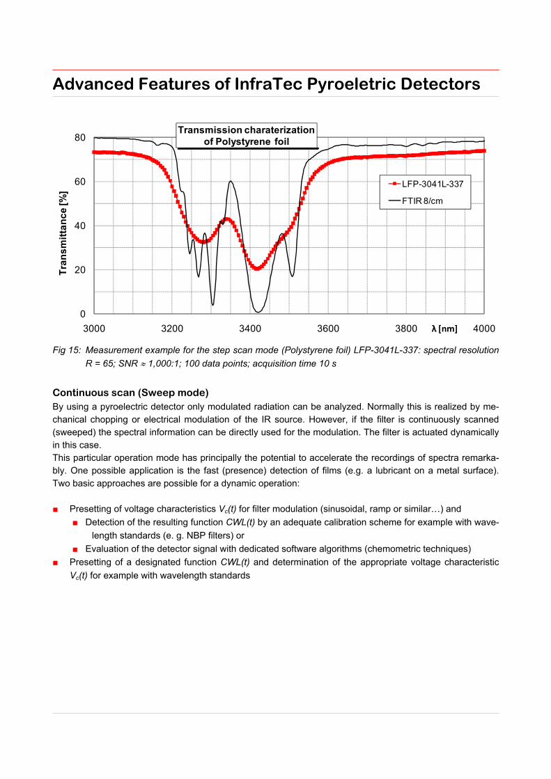
As an example for measurements with the step-scan mode, figure 34 shows spectra of a polystyrene foil. The red squares are the ‘steps’ of the FPF (LFP-3041L-337), whereas the solid line is measured with an FTIR spectrometer for comparison.
Advanced Features of InfraTec Pyroeletric Detectors
0
20
40
60
80
3000 3200 3400 3600 3800 4000
Tra
ns
mit
tan
ce
[%]
λ [nm]
Transmission charaterizationof Polystyrene foil
LFP-3041L-337
FTIR 8/cm
Fig 15: Measurement example for the step scan mode (Polystyrene foil) LFP-3041L-337: spectral resolution
R = 65; SNR 1,000:1; 100 data points; acquisition time 10 s
Continuous scan (Sweep mode) By using a pyroelectric detector only modulated radiation can be analyzed. Normally this is realized by me-chanical chopping or electrical modulation of the IR source. However, if the filter is continuously scanned (sweeped) the spectral information can be directly used for the modulation. The filter is actuated dynamically in this case. This particular operation mode has principally the potential to accelerate the recordings of spectra remarka-bly. One possible application is the fast (presence) detection of films (e.g. a lubricant on a metal surface). Two basic approaches are possible for a dynamic operation: Presetting of voltage characteristics Vc(t) for filter modulation (sinusoidal, ramp or similar…) and
Detection of the resulting function CWL(t) by an adequate calibration scheme for example with wave-
length standards (e. g. NBP filters) or
Evaluation of the detector signal with dedicated software algorithms (chemometric techniques)
Presetting of a designated function CWL(t) and determination of the appropriate voltage characteristic
Vc(t) for example with wavelength standards

Advanced Features of InfraTec Pyroeletric Detectors
40
60
80
100
120
3100 3300 3500 3700
85%
87%
89%
91%
93%
95%
97%
99%
101%
103%
105%
0 100 200 300 400 500 600 700
Tra
ns
mit
tan
ce
[%]
FT
IR
λ [nm]FTIR
No
rma
lize
d d
ete
cto
r s
ign
al
scantime [ms]LFP-3041L-337
Transmission characterization of 2.2 Vol% Methane
LFP-3041L-337
FTIR 4/cm
Fig 16: Measurement example for the sweep mode with dynamic filter tuning (methane)
Figure 35 gives an example for the dynamic operation. The IR source is working in DC operation, while the filter goes through the desired wavelength range. Except for the DC-portion, the whole spectral information is contained in the generated detector signal. For the filter actuation and signal processing the dynamic proper-ties of both, filter and detector, have to be considered.
1.6 6BSummary
With the extension of our product range by variable color detectors additional technologies are available for our customers. All types of our multispectral detectors are complementing one another: Conventional dual and quad channel detectors can be used in competitive volume applications
Our dual and quad channel beamsplitter detectors with one aperture are used as long term stable and
very accurate measuring modules for different spectral channels
Variable color detectors with a high SNR allow a more flexible operation of the analyzer enabling for
example the detection of adjoining or overlapping absorption bands. They are also of interest for applica-
tions, where more than 4 spectral channels shall be scanned within a short time frame.