Application Note - Passive filters
17
European Copper Institute APPLICATION NOTE PASSIVE FILTERS Stefan Fassbinder, European Copper Institute October 2011 ECI Publication No Cu0111 Available from www.leonardo-energy.org/node/134981
-
Upload
european-copper-institute -
Category
Technology
-
view
664 -
download
1
Transcript of Application Note - Passive filters

European Copper Institute
APPLICATION NOTE PASSIVE FILTERS
Stefan Fassbinder, European Copper Institute
October 2011
ECI Publication No Cu0111
Available from www.leonardo-energy.org/node/134981
Publication No Cu0111
Issue Date: October 2011
Page i
Document Issue Control Sheet
Document Title: Application Note - Passive filters
Publication No: Cu0111
Issue: 02
Release: October 2011
Author(s): Stefan Fassbinder
Reviewer(s): Noel Montrucchio (English Upgrade)
Document History
Issue Date Purpose Prepared Approved
1 June 2003 Initial release
2 October
2011
Summary added. Small adaptations.
English Upgrade. Added to GPG.
3
Disclaimer
While this publication has been prepared with care, European Copper Institute and other contributors provide
no warranty with regards to the content and shall not be liable for any direct, incidental or consequential
damages that may result from the use of the information or the data contained.
Copyright© European Copper Institute.
Reproduction is authorised providing the material is unabridged and the source is acknowledged.
Publication No Cu0111
Issue Date: October 2011
Page ii
CONTENTS
Summary ........................................................................................................................................................ 1
Basics of reactive power compensation ................................................................................................................. 2
Dedicated filtering circuits for individual frequencies ............................................................................................ 3
Reactive compensation .......................................................................................................................................... 4
Combined compensation and filtering ................................................................................................................... 4
Wattless current ....................................................................................................................................... 5
Sample measurements ............................................................................................................................. 7
How can the performance be improved? ................................................................................................ 8
Central or dispersed? ............................................................................................................................... 9
Mind the L/C ratio .................................................................................................................................. 12
Do not filter sound frequency signals away! .......................................................................................... 13
Conclusions ................................................................................................................................................... 14
References .................................................................................................................................................... 14
Publication No Cu0111
Issue Date: October 2011
Page 1
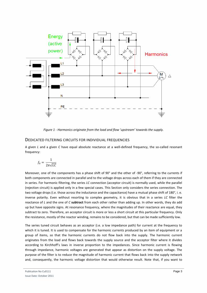
SUMMARY Harmonic currents can originate from systems that do not contain energy and in which the sign of the current
matches that of the voltage throughout the cycle (e.g. a phase-angle controller for an incandescent lamp). The
term ‘wattless current’ is sometimes applied to harmonic currents that do not have substantial voltage
harmonics of the same orders to multiply them. The result is a product of current and voltage that is zero.
Those harmonic currents have a lot in common with reactive currents:
They are both undesirable in that they require part of the capacity of generators, cables, and
transformers, while contributing nothing to the generation and transport of electrical energy.
They both cause additional losses—because the voltage drop is phase-related to the current so the
product is real and non-zero.
Harmonics originate mostly from the power-consuming load and flow back to the energy source,
against the normal energy flow (Figure 1). (An exception is a renewable energy source connected to
the grid by a power electronic converter where the harmonics flow away from the source.)
Fundamental reactive power does not have a defined direction—intake of inductive reactive power is
synonymous with output of capacitive reactive power and vice versa.
It should therefore be possible to combat both reactive power and harmonics by similar means.
This is indeed the case. This publication explains how it can be accomplished effectively and how dedicated
filters can be created for individual frequencies.
In addition to the general principles and guidelines, this paper tackles the importance of using high-quality
components for accurate filter tuning. It discusses whether to compensate centrally or dispersed, and how to
choose the inductor for a given L/C ratio. Finally, it warns that special caution must be taken to (i) prevent the
filtering out of sound frequencies used by utilities, and (ii) that despite filtering, harmonics should still be taken
into account for rating cables and equipment.
Publication No Cu0111
Issue Date: October 2011
Page 2
BASICS OF REACTIVE POWER COMPENSATION
In publication Cu0108 of this Guide it was explained why reactive power should be compensated and how this
is best accomplished. Fundamental reactive power is always an onerous oscillation of energy. The basic facts
are restated below in slightly greater detail to ensure a thorough understanding:
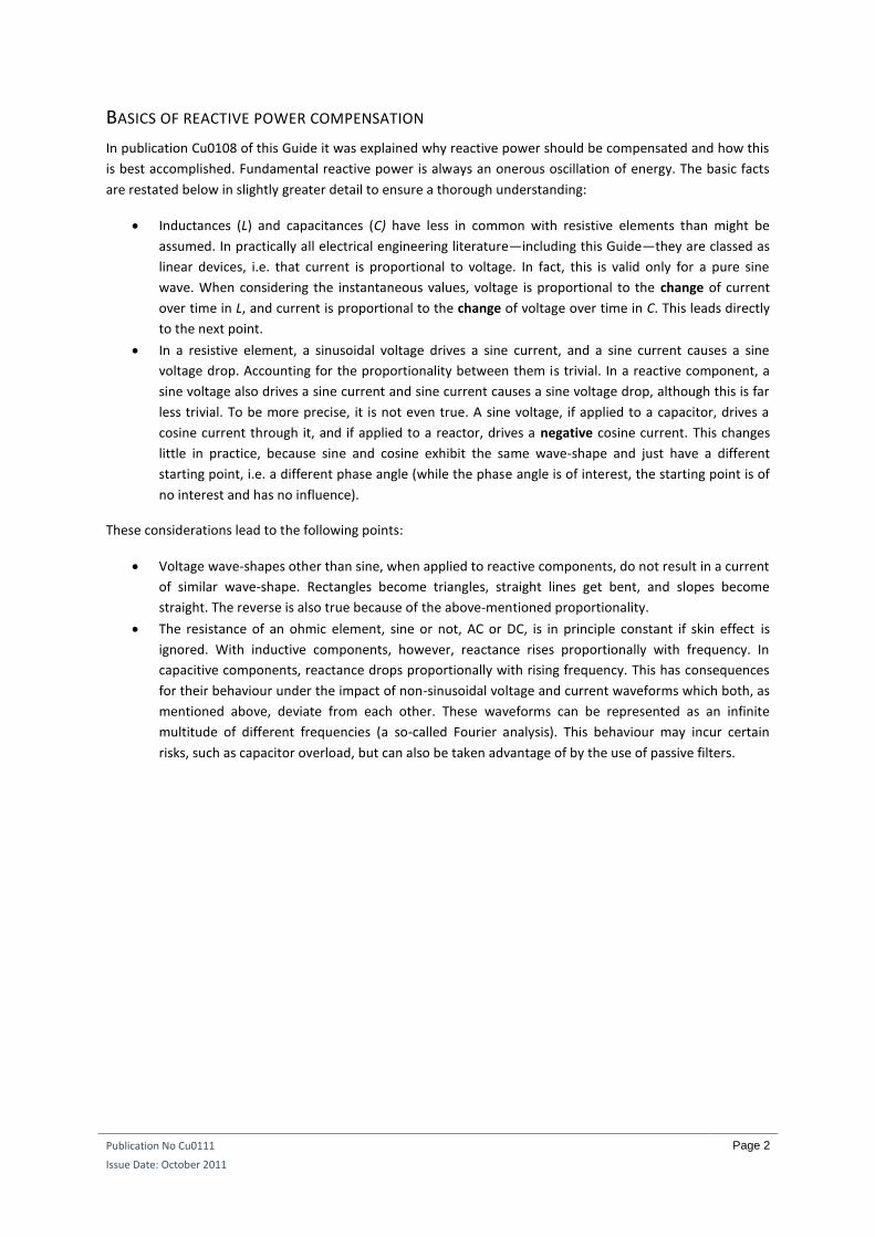
Inductances (L) and capacitances (C) have less in common with resistive elements than might be
assumed. In practically all electrical engineering literature—including this Guide—they are classed as
linear devices, i.e. that current is proportional to voltage. In fact, this is valid only for a pure sine
wave. When considering the instantaneous values, voltage is proportional to the change of current
over time in L, and current is proportional to the change of voltage over time in C. This leads directly
to the next point.
In a resistive element, a sinusoidal voltage drives a sine current, and a sine current causes a sine
voltage drop. Accounting for the proportionality between them is trivial. In a reactive component, a
sine voltage also drives a sine current and sine current causes a sine voltage drop, although this is far
less trivial. To be more precise, it is not even true. A sine voltage, if applied to a capacitor, drives a
cosine current through it, and if applied to a reactor, drives a negative cosine current. This changes
little in practice, because sine and cosine exhibit the same wave-shape and just have a different
starting point, i.e. a different phase angle (while the phase angle is of interest, the starting point is of
no interest and has no influence).
These considerations lead to the following points:
Voltage wave-shapes other than sine, when applied to reactive components, do not result in a current
of similar wave-shape. Rectangles become triangles, straight lines get bent, and slopes become
straight. The reverse is also true because of the above-mentioned proportionality.
The resistance of an ohmic element, sine or not, AC or DC, is in principle constant if skin effect is
ignored. With inductive components, however, reactance rises proportionally with frequency. In
capacitive components, reactance drops proportionally with rising frequency. This has consequences
for their behaviour under the impact of non-sinusoidal voltage and current waveforms which both, as
mentioned above, deviate from each other. These waveforms can be represented as an infinite
multitude of different frequencies (a so-called Fourier analysis). This behaviour may incur certain
risks, such as capacitor overload, but can also be taken advantage of by the use of passive filters.
Publication No Cu0111
Issue Date: October 2011
Page 3
Figure 1 - Harmonics originate from the load and flow ‘upstream’ towards the supply.
DEDICATED FILTERING CIRCUITS FOR INDIVIDUAL FREQUENCIES
A given L and a given C have equal absolute reactance at a well-defined frequency, the so-called resonant
frequency:
√
Moreover, one of the components has a phase shift of 90° and the other of -90°, referring to the currents if
both components are connected in parallel and to the voltage drops across each of them if they are connected
in series. For harmonic filtering, the series LC connection (acceptor circuit) is normally used, while the parallel
(rejection circuit) is applied only in a few special cases. This Section only considers the series connection. The
two voltage drops (i.e. those across the inductance and the capacitance) have a mutual phase shift of 180°, i. e.
inverse polarity. Even without resorting to complex geometry, it is obvious that in a series LC filter the
reactance of L and the one of C subtract from each other rather than adding up. In other words, they do add
up but have opposite signs. At resonance frequency, where the magnitudes of their reactance are equal, they
subtract to zero. Therefore, an acceptor circuit is more or less a short circuit at this particular frequency. Only
the resistance, mostly of the reactor winding, remains to be considered, but that can be made sufficiently low.
The series tuned circuit behaves as an acceptor (i.e. a low impedance path) for current at the frequency to
which it is tuned. It is used to compensate for the harmonic currents produced by an item of equipment or a
group of items, so that the harmonic currents do not flow back into the supply. The harmonic current
originates from the load and flows back towards the supply source and the acceptor filter where it divides
according to Kirchhoff’s laws in inverse proportion to the impedances. Since harmonic current is flowing
through impedance, harmonic voltages are generated that appear as distortion on the supply voltage. The
purpose of the filter is to reduce the magnitude of harmonic current that flows back into the supply network
and, consequently, the harmonic voltage distortion that would otherwise result. Note that, if you want to
Publication No Cu0111
Issue Date: October 2011
Page 4
reduce the potential voltage harmonic of a certain order by more than 50% with an acceptor circuit, it must
have lower impedance than the network’s short circuit impedance at that specific frequency.
Since there are losses in passive filters and reactive compensators, some energy is lost as heat. As usual,
keeping losses low requires more material—larger cross-section conductors, with better and more magnetic
steel—and therefore increases the cost. In extreme cases, using low cost (= high loss) units means that the
money saved through compensating reactive power is lost again as active losses in the compensator. The usual
consideration is that the cost of reactive power is normally not as high as that of active power. The
magnetizing and eddy current losses in the steel and the dielectric and ohmic losses in the capacitor are
normally so low that they do not need to be taken into account as far as the behaviour of the filter is
concerned. However, these losses result in the generation of heat and are an important design consideration.
They are, in fact, the reason for overheating and subsequent failure in overload conditions. Losses also
influence the filtering quality: the sharpness of separating the wanted from the undesired frequency is a lot
better when losses are low. A filtering quality factor is defined, incurring the quotient of reactance by
resistance.
REACTIVE COMPENSATION
Reactive current compensators are affected by harmonics (as explained in Cu0108) and it is recommended
that power factor correction capacitors are de-tuned. In fact, some electricity suppliers require de-tuning.
‘De-tuning’ means connecting a reactor in series with the PFC capacitor so that the capacitor/inductor
combination behaves as a capacitor at the fundamental supply frequency but has a defined behaviour for
harmonic frequencies.
A simple (not de-tuned) PFC is actually part of an acceptor circuit formed with inductive components in the
network, especially with stray inductance from transformers. Resonance will lead to excessive harmonic
currents and to excessive voltage drops within the proximity of the transformers affected.
It has been explained that, at the tuned frequency, the magnitude of the voltage drops across the inductive
and capacitive elements is the same but with 180o phase difference, giving a resultant zero voltage drop.
However, at or near resonance, the voltage drop across each element is much higher than that which would be
expected across, for example, the network impedance at the point of common coupling. Therefore,
considering the elements individually, each has a high magnitude voltage drop across it even though the
resultant voltage drop across the combination is small. This explains why ‘accidental’ acceptor circuits (e.g. a
PFC capacitor with stray inductance) are a problem. The installation is across the capacitive element and sees
these amplified voltages. When the inductive element is intentionally added, the installation is across the
resultant acceptor voltage drop. The excess voltages remain inside the compensator cubicle, for instance
across the capacitors designed for these voltage values. But at its outside terminals, no resonance or magnified
voltages can appear.
Useful reminder: there are harmonic frequencies at 100 Hz intervals from 50 Hz to well over 1 KHz, especially
where single phase non-linear loads are in use, so there is ample scope for resonances to be excited.
COMBINED COMPENSATION AND FILTERING
In practice, the functions of reactive power compensation and harmonic current filtering are often combined.
It is usual to set the resonant frequency of the LC circuit at a non-harmonic frequency because compensators
can easily be overloaded. The rating of the reactors is normally given as a percentage of the rated reactive
power of the capacitors at 50 Hz. For example, a 5% de-tuning rate means that 1/20 of the voltage drops across L
and 21
/20 drop across C, subtracting to 100% overall. At 20 times the frequency, for example 1,000 Hz, the ratio
Publication No Cu0111
Issue Date: October 2011
Page 5
would be reversed, so the resonant frequency where XL and XC are equal lies in the middle between these two
frequencies. This precise point is:
√
Another common value, 7%, yields a resonant frequency of 189 Hz, thus avoiding an approximate short circuit
for any harmonic. Because the LC combination is across the supply network, harmonics from external sources
can flow through it just as easily as the internal sources for which it was designed. Therefore, if you operate
such a filter but your neighbour does not, you may have to oversize it. In any event, over sizing will not only
avoid unforeseen overload but also improve the filter quality; that is, separate the desired from the undesired
frequencies more sharply, with reduced energy losses. This effect is reduced if the installation is isolated from
others by a distribution transformer with its associated inductance.
Active harmonic conditioners (AHC) are normally also operated mains parallel (as shunts). Yet, the situation is
slightly different. These electronic devices analyse the current harmonics in the load side, and generate the
exact opposite of these harmonics for the next cycle (identical wave forms but with inverse sign, or half a
period phase shift). As a result, harmonic currents are supplied from the conditioner and fundamental current
from the supply. If the total harmonic current requirement is higher than the capacity of the conditioner, it
merely limits compensation––still allowing partial correction, but leaving some of the harmonic current to be
drawn from the supply. AHCs act only on the harmonic currents that are present on the load side, i.e. at the
current measuring point. Effectively, this means that, as long as the rating of the AHC is sufficient for the load,
this particular load will not impair the power quality of the supply. If that load is inactive, the conditioner will
also be inactive.
However, the passive filter is, in a sense, always active in that it is always on the alert, waiting for ‘its’
harmonic to appear. Passive acceptor circuits tuned to resonance frequencies of, for example 150 Hz (11% of
de-tuning reactance) or 250 Hz (4% of de-tuning reactance), accept any amplitude of the third and the fifth
current harmonic well into the overload range. This depends on the amount of harmonics found in the mains
and does not depend on the impact of one specific load. For this reason, they should be generously
dimensioned. This is not usually a cost issue when compared to active conditioners.
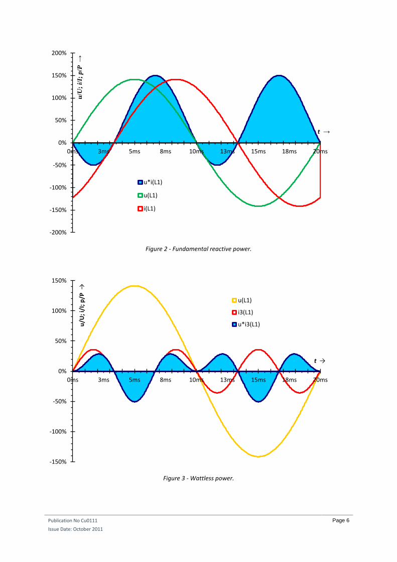
WATTLESS CURRENT As has already been mentioned, where reactive power occurs in a distribution system (usually inductive
reactive power), part of the energy in the line is in effect not transferred from source to load. Rather it
oscillates from a capacitance to a reactance and back again at a frequency of 100 Hz. At certain time intervals,
voltage and current have opposite polarities (Figure 2). Likewise, the picture appears very similar with
harmonics. In Figure 3 the power of the third current harmonic has been plotted in isolation. The power
transferred is the product of the third current harmonic times the voltage present in the line, assuming the line
voltage is still a pure sine wave. It can be shown that the areas above and below the abscissa cancel, meaning
that on average no energy is transmitted. The third harmonic current is therefore absolutely wattless.
Publication No Cu0111
Issue Date: October 2011
Page 6
Figure 2 - Fundamental reactive power.
Figure 3 - Wattless power.
-200%
-150%
-100%
-50%
0%
50%
100%
150%
200%
0ms 3ms 5ms 8ms 10ms 13ms 15ms 18ms 20ms
u/U
; i/I;
p/P
→
t →
u*i(L1)
u(L1)
i(L1)
-150%
-100%
-50%
0%
50%
100%
150%
0ms 3ms 5ms 8ms 10ms 13ms 15ms 18ms 20ms
u/U
; i/
I; p
/P →
t →
u(L1)
i3(L1)
u*i3(L1)
Publication No Cu0111
Issue Date: October 2011
Page 7
Nevertheless, since harmonics do cause additional losses, there must be some active power associated with
them. This apparent contradiction originates from the incorrect assumption that the supply voltage was free of
all harmonics. This is impossible, since the moment there is any 150 Hz current flowing, it will cause some
active—and probably also reactive—150 Hz voltage drop. This means that as soon as there is any additional
frequency contained within the current, there will also be a certain amount of the same frequency in the
voltage. Only when both voltage and current of the same frequency are present can active power occur at this
frequency. It should be clear by this point that this will always be the case to some extent. The resistance in
the installation circuit causes a voltage drop that is exactly in phase with the current and therefore results in
real power dissipation. This occurs regardless whether the current is real, reactive, or harmonic.
SAMPLE MEASUREMENTS Fluorescent lamps are the only common device where putting the most efficient method of compensation at
the point of origin within the luminaire, is a common practice. This is most efficient because only real current
flows in the installation wiring, the reactive component having already been compensated for within the
fitting.
When centrally installed units are used, combining the reactive current compensator with the harmonic filter
solves several problems simultaneously with the same device. The advantage of a centrally installed unit, with
appropriate control, is that since not all equipment operates simultaneously, it is often possible to install
rather less total compensation capacity than would be the case if all equipment were locally compensated. It
also reduces the risk of overcompensating motors. Using a combined filter/compensation device removes the
risk of resonance and ensures that those harmonics within the range of the filter are attenuated.
The risk of attracting pollution from the supply while sweeping one’s own is not as high as is generally
assumed, at least not when the premise is supplied by its own distribution transformer. The voltage drop in a
transformer, described in terms of its short circuit voltage, is largely inductive. Therefore, a transformer with a
short circuit voltage rating of 4% has a relative reactance of nearly 12% at 150 Hz and close to 20% at 250 Hz. If
the neighbouring premises also use their own transformers, the impedance between the two doubles again.
However, the impedance of a transformer to harmonics varies a great deal depending upon:
The vector group of the transformer, i. e. whether there is any winding present.
Whether the harmonic in question is triple-n (its order divisible by 3) or other order.
The following series of single-phase measurements will show how acceptor circuits can effectively and
inexpensively mitigate harmonic problems.
For a single-phase model test, use, for example, two magnetic ballasts for 58 W fluorescent lamps. Their
winding resistance is 13.8 , and inductance 878 mH. Connecting them in series with capacitors, one with a
capacitance of 1.3 µF and one with 0.46 µF, provides acceptor circuits with resonance frequencies of 150 Hz
and 250 Hz. When connected to the mains in a residential area on a Saturday night during a football match
when all the TV sets and a few compact fluorescent lamps are on and the electric stoves are off, the voltage
may have a total harmonic distortion (THD) of around 4.7%. This distortion consists mainly of the fifth
harmonic contributing around 10 V; the others being insignificant. The third harmonic, though dominating the
input currents of TV sets and similar appliances, has little effect upon the voltage as long as the loads are more
or less balanced (due to the presence of delta windings in transformers). In a single-phase supply, or if only
one phase is loaded, this would not be the case. In a usual system, however, with the non-linear loads largely
balanced, not very much happens in the 150 Hz filter. However, in the 250 Hz filter, one will measure ≈75 mA
of 250 Hz current. This is double the current one finds at 50 Hz, even though a voltage of approximately 230 V
is applied to the filter at 50 Hz and only ≈10 V at 250 Hz. This underlines the basic filtering capability of the
method. It has no measurable effect on the supplying voltage, though, because the filter’s rating (670 mA,
Publication No Cu0111
Issue Date: October 2011
Page 8
something around 180 VAr) is much too small and its winding resistance much too high to clean up a network
loaded with an estimated 400 kVA.
To demonstrate its full capability, the filter model would have to clean up a network of adequate ratings,
ideally with a substantial distortion that needs to be mitigated. This can be found if a phase-angle controlled
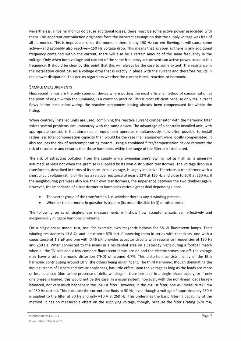
dimmer controlling an adequate load is in the network. An example would be dimming a 200 W incandescent
lamp down to 100 W. The dimmer isolates the load from the mains to some extent and thus provides the
desired ‘island’ network. Logically, as the controlled load is purely resistive, the voltage across the lamp and
the current through the lamp have the same heavy distortions, quantitatively and qualitatively. Can this be
mitigated by means of filters? The answer is yes (Figure 4). Paralleling the affected load with the two acceptor
circuits reduces THD of both voltage across and current through the load from ≈61% to ≈37%. In many cases,
this degree of improvement is just enough to move from a disturbed to a functioning system. Nobody needs
an absolutely clean sine wave, except of course certain measurement labs and calibration installations.
The results also reveal that the 150 Hz acceptor circuit is no longer idling and cannot be viewed as superfluous.
Rather, it contributes to the largest part of the improvement. Its current is now 395 mA at 150 Hz (in addition
to 22 mA at 250 Hz slightly assisting the other acceptor circuit). The 250 Hz current in the 250 Hz filter is 184
mA, still significant, but less than the 150 Hz current. This is typical for a single-phase load, operated more or
less in isolation from the three-phase mains.
Figure 4 - Voltage and current of a 200 W incandescent lamp dimmed down to 100 W, ordinary and with 3rd
and 5th harmonic acceptor circuits.
HOW CAN THE PERFORMANCE BE IMPROVED? Of course a 350 Hz filter could be added, but that would not address the core of the problem. Despite the
presence of third and fifth harmonic filters, the third (34 V) and the fifth (26 V) still each exceed the share of
the seventh (Figure 4) even though a 350 Hz filter is missing. The filters under test appear to have a quality
problem. Indeed, 13.8 of active resistance is quite high. If the 150 Hz impedance of the third harmonic
acceptor circuit were zero, as it should ideally be, the 150 Hz voltage would also have to be zero. What we find
in reality is a voltage of 34 V driving a current of 395 mA in the 150 Hz filter and 26 V driving 184 mA in the 250
Hz filter. Both yield much more than 13.8 . There must therefore be substantially more losses through eddy
currents and hysteresis due to poor steel quality. Inductance vagaries (variation with current, non-constant
inductance, et cetera) hamper precise tuning to a targeted frequency. This shows how important it is to
choose high quality components, especially with respect to the reactor, since it causes most of the losses and
inaccuracies. All resistive/eddy current/hysteresis losses end up with inaccurate filter tuning, so it is most
important to select dedicated high-quality components instead of using readily available reactors which are
inexpensive but designed for uses where losses, tolerances, and inconsistency of ratings are not as significant.
Publication No Cu0111
Issue Date: October 2011
Page 9
Passive filtering is already one of the least costly methods of dealing with harmonics. It consists only of a minor
modification to the reactive power compensator in operation. Further skimping can often become quite
expensive at the end of the day.
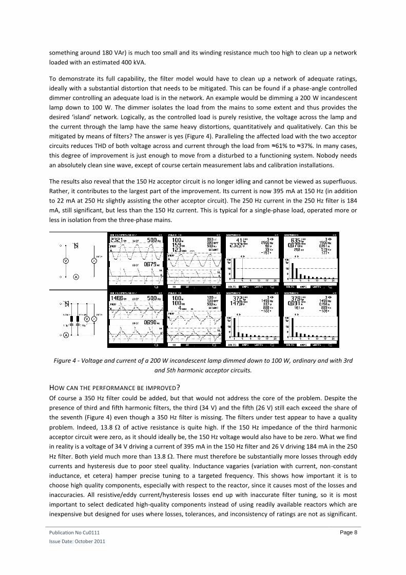
CENTRAL OR DISPERSED? A further question accompanying the selection of the right model is the star or delta connection.
Compensators usually come in delta connection. For a passive filter, this arrangement will only be partially
effective, since the most prevalent harmonics in office environments (the third) originate from single phase
equipment and flow between phase and neutral. There may also be some intermediate solutions with the
capacitors connected in delta but designing the de-tuning reactors as three-phase neutral reactors. Your
supplier should be able to advise which design is best for your system.
Figure 5 - What uncontrolled resonance may do…
As stated earlier, acceptors pass harmonic current in a manner that does not allow them to flow back into the
supply. It has to be remembered that the harmonic currents still flow around the installation. In fact, they
provoke an increase of TRMS current between the source of harmonics and the filter because the loop
impedance has decreased. All the measures are still required that would normally be taken within the
installation to cope with the effect of harmonic currents. In the presence of a filter, the sum of the load and
filter currents (i.e. that required to be supplied) is lower than the load current alone without a filter, but the
load current alone will be larger than it would have been without any filter in the proximity. From this point of
view, highly dispersed filtration is the more efficient solution since the increased currents flow around smaller
loops. Note however that it will be more costly.
Under no circumstances can the presence of any filtering equipment be used as a pretext to return to old TN-C
wiring practices formerly used in some countries or to install under-sized neutral conductors. TN-C wiring
systems allow neutral currents, including harmonics, to flow in extraneous conductive parts.
Publication No Cu0111
Issue Date: October 2011
Page 10
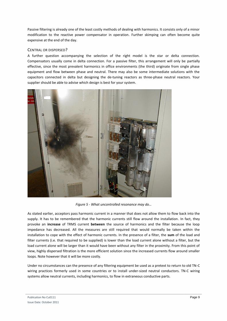
Figure 6 – This is what you wanted…
Figure 7 – And this is what you may get…
-90°
-60°
-30°
0°
30°
60°
90°
0.0Ω
0.1Ω
0.2Ω
0.3Ω
0.4Ω
0.5Ω
0.6Ω
0.7Ω
0.8Ω
0.9Ω
1.0Ω
100Hz 110Hz 120Hz 130Hz 140Hz 150Hz 160Hz 170Hz 180Hz 190Hz 200Hz
φ →
Z →
f →
Z
φ
-90°
-60°
-30°
0°
30°
60°
90°
0.0Ω
0.1Ω
0.2Ω
0.3Ω
0.4Ω
0.5Ω
0.6Ω
0.7Ω
0.8Ω
0.9Ω
1.0Ω
100Hz 110Hz 120Hz 130Hz 140Hz 150Hz 160Hz 170Hz 180Hz 190Hz 200Hz
φ →
Z →
f →
Z
φ
Publication No Cu0111
Issue Date: October 2011
Page 11
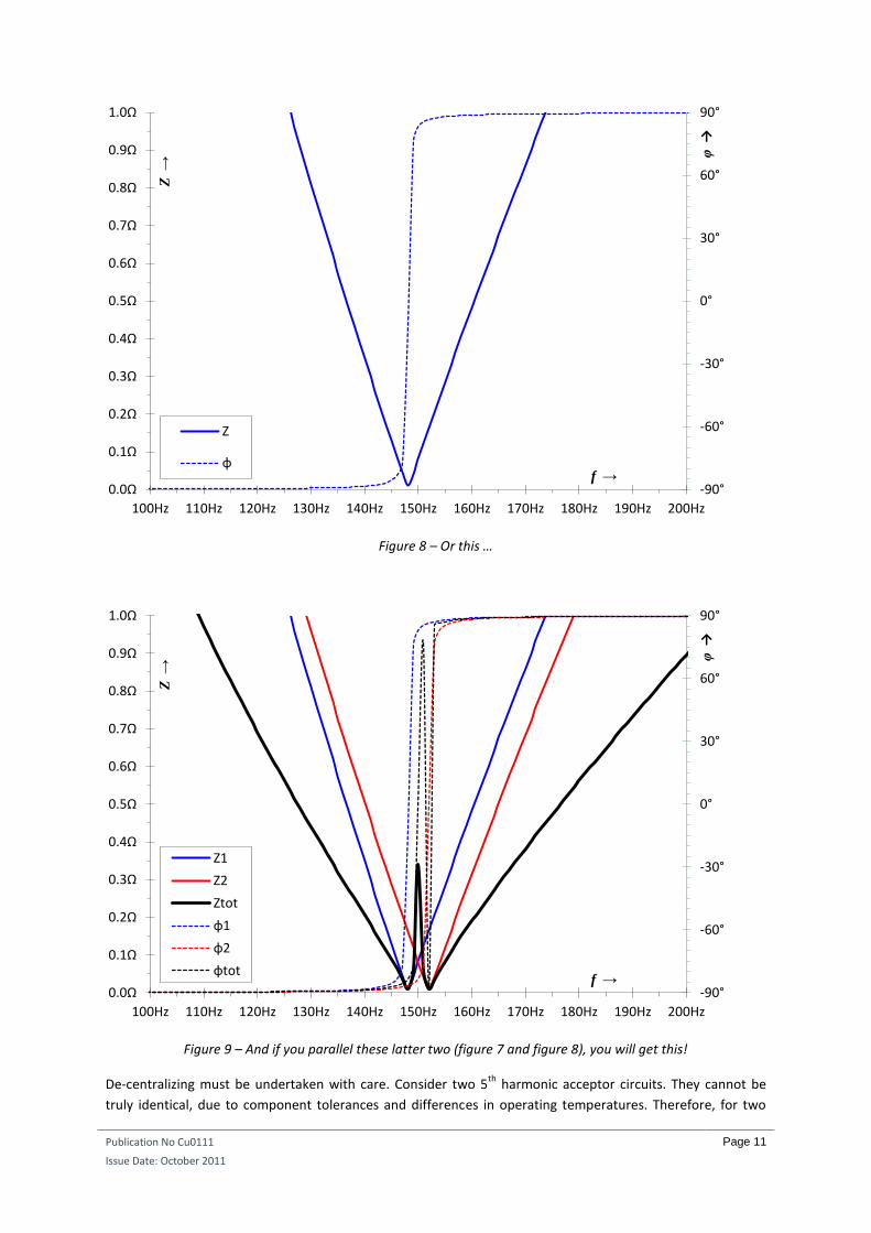
Figure 8 – Or this …
Figure 9 – And if you parallel these latter two (figure 7 and figure 8), you will get this!
De-centralizing must be undertaken with care. Consider two 5th
harmonic acceptor circuits. They cannot be
truly identical, due to component tolerances and differences in operating temperatures. Therefore, for two
-90°
-60°
-30°
0°
30°
60°
90°
0.0Ω
0.1Ω
0.2Ω
0.3Ω
0.4Ω
0.5Ω
0.6Ω
0.7Ω
0.8Ω
0.9Ω
1.0Ω
100Hz 110Hz 120Hz 130Hz 140Hz 150Hz 160Hz 170Hz 180Hz 190Hz 200Hz
φ →
Z →
f →
Z
φ
-90°
-60°
-30°
0°
30°
60°
90°
0.0Ω
0.1Ω
0.2Ω
0.3Ω
0.4Ω
0.5Ω
0.6Ω
0.7Ω
0.8Ω
0.9Ω
1.0Ω
100Hz 110Hz 120Hz 130Hz 140Hz 150Hz 160Hz 170Hz 180Hz 190Hz 200Hz
φ →
Z →
f →
Z1
Z2
Ztot
φ1
φ2
φtot
Publication No Cu0111
Issue Date: October 2011
Page 12
filters with a rated resonance frequency of 250 Hz, one may in fact resonate at 248 Hz and the other one at
252 Hz. At 250 Hz the former appears capacitive and the latter inductive, and together they form an
approximate or even perfect rejection circuit. This is precisely the opposite of the desired effect. Moreover, a
250 Hz current will circulate between the two and may overload both of them as well as the installation wiring
(Figure 5). Alternatively, if one of the filters happens to hit the 250 Hz precisely and the other one resonates at,
for example, 254 Hz, then the larger share of the 250 Hz pollution will use the former and may overload it,
while the latter one is idling. Unfortunately, the higher the quality factor, the more extreme this effect will be.
Indeed, a higher quality factor of an acceptor/rejection circuit means a steeper decline/incline of impedance
while approaching the resonant frequency. Therefore, there must be some impedance between each filter so
that they are to some extent isolated from each other and do not appear to be directly in parallel. This implies
that wide dispersal of a large number of small filters is not a practical proposition and, as always in
engineering, an appropriate balance must be sought.
MIND THE L/C RATIO Each frequency has an infinite number of LC pairs for which it is the resonant frequency. The value of the
capacitor determines the reactive compensation available (which cannot, of course, be zero) leaving the
inductor to be specified to determine the harmonic behaviour. Once the selection is made, it is fixed forever.
This can be a disadvantage of passive filters. For example, the 150 Hz and 250 Hz model filters discussed earlier
drew 50 Hz currents of 100 mA and 37 mA, respectively. This is quite low compared to the measured harmonic
currents, because these filters were designed with a high value of L and a small value of C. One solution is to
arrange the filters in smaller groups and switch them on individually to match the reactive compensation
required as is done with controlled compensators. Obviously, the filter capacity will also increase as the
reactive capacity increases, but this may be desirable because the harmonic current will also be reduced at
reduced load.
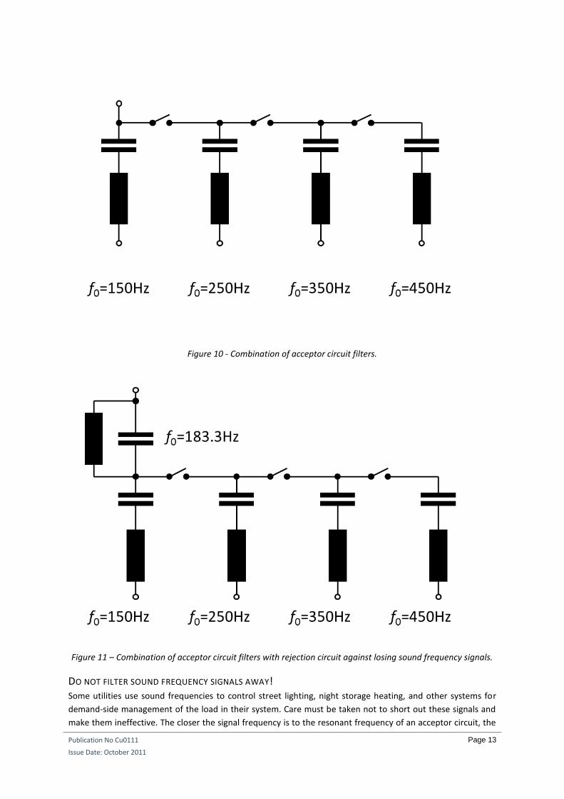
Consideration should also be given whether to shut off the filters for the higher harmonics when less
compensation is needed, as suggested in Figure 10. Although this is not a perfect solution, it is a very cost-
effective one. The passive filter we are talking about is nothing more than a modified design or adequate
selection of a compensator that is needed anyway. When applying this method, however, make sure that the
cut-out is done top-down (from right to the left in Figure 10) as described in Cu0108. Otherwise, one or the
other of the higher frequency acceptor circuits may resonate with an inductive network element at one of the
lower harmonics.
Publication No Cu0111
Issue Date: October 2011
Page 13
Figure 10 - Combination of acceptor circuit filters.
Figure 11 – Combination of acceptor circuit filters with rejection circuit against losing sound frequency signals.
DO NOT FILTER SOUND FREQUENCY SIGNALS AWAY! Some utilities use sound frequencies to control street lighting, night storage heating, and other systems for
demand-side management of the load in their system. Care must be taken not to short out these signals and
make them ineffective. The closer the signal frequency is to the resonant frequency of an acceptor circuit, the
Publication No Cu0111
Issue Date: October 2011
Page 14
lower the impedance of that circuit is at that signal frequency. When the installation is fed from a dedicated
transformer, the associated inductance may well be high enough to ensure that there is no effect on the
signalling frequencies. Otherwise, it may be necessary to install a parallel LC rejection filter tuned to the
signalling frequencies as shown in Figure 7 (with a utility that uses 183.3 Hz signals, 13
/3 of the mains
frequency).
CONCLUSIONS It incurs very little additional effort and cost to mitigate dominant harmonics together with the compensation
of fundamental reactive power. Compensation is carried out anyway and most compensators today already
utilize de-tuning reactors. In most cases, tuning the resonant frequencies of such a system to any possible
harmonic frequencies in the power system is deliberately avoided. Greater benefit can be realized by designing
for resonance. Harmonic currents are more effectively reduced and the risk of overloading the compensator is
not as high as generally assumed. A certain degree of reserve, of course, has to be installed. This is not a
problem since this brings about a better cleaning effect and better energy efficiency at very little extra cost.
Harmonic currents cause more problems for the supply network than reactive currents, so it is foreseeable
that utilities will start to charge for harmonics dissipation as well as fundamental reactive power. It makes no
sense whatsoever to charge for fundamental reactive power while not doing so for harmonics.
There is no case where the installation of filtering equipment, except filters installed with or even inside a load,
can be used as a convincing argument for failing to up-size neutrals or take account of harmonics in rating
cables and other equipment.
Keeping the system’s impedance low is of vital importance. This is especially true when filtering is installed;
even more so than when it is not. Otherwise, the filter’s effects may be adverse!
REFERENCES [1] Fender, Manfred: Vergleichende Untersuchungen der Netzrückwirkungen von Umrichtern mit Zwischenkreis
bei Beachtung realer industrieller Anschluss-Strukturen, Wiesbaden 1997.


![IV- Passive Filters[Full Ans]](https://static.fdocuments.in/doc/165x107/563db9dd550346aa9aa0a869/iv-passive-filtersfull-ans.jpg)