Application Note of TD-SCDMA Measurement · PDF file1.00 July 2015 MT8820B/20C/21C TD-SCDMA...
40
Revision History Ver. No Date Contents Related product software version 1.00 July 2015 MT8820B/20C/21C TD-SCDMA Application Note (Ver 1.00) succeeded MT8820B/C TD-SCDMA Application Note (Ver 4.00). Overall: Changed model name from MT8820B/C to “unit” Added software specification for MT8821C MX882007C Ver23.01 MX882107C Ver30.00 TD-SCDMA Measurement Radio Communication Analyzer MT8820B/MT8820C/MT8821C
Transcript of Application Note of TD-SCDMA Measurement · PDF file1.00 July 2015 MT8820B/20C/21C TD-SCDMA...

Revision History
Ver. No Date Contents Related product software version
1.00 July 2015 MT8820B/20C/21C TD-SCDMA Application Note (Ver 1.00) succeeded MT8820B/C TD-SCDMA Application Note (Ver 4.00). Overall: Changed model name from MT8820B/C to “unit” Added software specification for MT8821C
MX882007C Ver23.01 MX882107C Ver30.00
TD-SCDMA Measurement Radio Communication Analyzer MT8820B/MT8820C/MT8821C
2
Contents 1. TD-SCDMA Measurement Software ............................................................................... 4
1.1. SPECIFICATIONS ....................................................................................................................................... 4
1.1.1. For MT8820B/20C .......................................................................................................................... 4
1.1.2. For MT8821C .................................................................................................................................. 7
1.2. 3GPP MEASUREMENT SPECIFICATION (3GPP TS 34.122 V11.5.0) TABLE ...................................................11
1.3. TRX MEASUREMENT (FUNDAMENTAL MEASUREMENT) ............................................................................... 14
1.3.1. Test Loop Mode Connection (Single Code) ............................................................................... 14
1.3.2. Test Loop Mode Disconnection .................................................................................................. 14
1.3.3. Switching Channel Coding during Connection ......................................................................... 14
1.3.4. Channel Switching by Handover ................................................................................................ 15
1.3.5. Switching Channel and Channel Coding (Single Code/Multi Code) by Handover ................. 15
1.3.6. Test Item Selection ...................................................................................................................... 15
1.3.7. 5.2 User Equipment maximum output power .......................................................................... 16
1.3.8. 5.3 UE frequency stability ........................................................................................................... 16
1.3.9. 5.4.2 Minimum output power .................................................................................................... 17
1.3.10. 5.4.3 Transmit OFF power, 5.4.4 Transmit ON/OFF Time mask ............................................ 17
1.3.11. 5.5.1 Occupied bandwidth ........................................................................................................ 18
1.3.12. 5.5.2.1 Spectrum emission mask ............................................................................................. 18
1.3.13. 5.5.2.2 Adjacent Channel Leakage power Ratio (ACLR) ......................................................... 19
1.3.14. 5.7.1 Error Vector Magnitude ................................................................................................... 19
1.3.15. 5.7.2 Peak code domain error .................................................................................................. 20
1.3.16. 6.2 Reference sensitivity level .................................................................................................. 20
1.3.17. Reduction of measurement time by batch processing .......................................................... 21
1.4. OPEN LOOP POWER CONTROL MEASUREMENT .......................................................................................... 22
1.4.1. 5.4.1 Open Loop Power Control in the Uplink (RX-middle) ...................................................... 22
1.4.2. 5.4.1 Open Loop Power Control in the Uplink (RX Upper dynamic end) ................................ 22
1.4.3. 5.4.1 Open Loop Power Control in the Uplink (RX-Sensitivity level) ........................................ 23
1.4.4. Continuous measurement of Open Loop Power Control ........................................................ 23
1.5. CLOSED LOOP POWER CONTROL MEASUREMENT (AUTOMATIC MEASUREMENT) ............................................ 24
1.5.1. 5.4.1.4 Closed loop power control ............................................................................................. 24
1.6. OTHER MEASUREMENT ............................................................................................................................ 25
1.6.1. 5.4.5 Out-of-synchronisation handling of output power for continuous transmission ........ 25
1.6.2. 5.4.6 Out-of-synchronisation handling of output power for discontinuous transmission ... 25
1.6.3. 6.3 Maximum Input Level ........................................................................................................... 26
1.6.4. 6.8 Spurious Emissions ............................................................................................................... 26
1.6.5. 7.2 Demodulation in static propagation conditions ................................................................. 27
1.7. HSDPA MEASUREMENT .......................................................................................................................... 28
1.7.1. HSDPA RMC Connection ............................................................................................................. 28
1.7.2. HSDPA RMC Disconnection ........................................................................................................ 28
1.7.3. Switching HSDPA Data Rate during connection. ...................................................................... 28
1.7.4. 5.2B User Equipment maximum output power with HS-SICH and DPCH .............................. 29
1.7.5. 5.5.2.1B Spectrum emission mask ............................................................................................. 30
1.7.6. 5.5.2.2B Adjacent Channel Leakage power Ratio (ACLR) with HS-SICH and DPCH ............... 30
1.7.7. 5.7.1B Error Vector Magnitude with HS-SICH and DPCH ......................................................... 31

3
1.7.8. 6.3A Maximum Input Level for HS-PDSCH Reception (16QAM) .............................................. 31
1.7.9. 9.3.3 Reporting of HS-DSCH Channel Quality Indicator (2.8 Mbps UE) .................................. 32
1.8. HSUPA MEASUREMENT .......................................................................................................................... 33
1.8.1. HSUPA RMC Connection ............................................................................................................. 33
1.8.2. HSUPA RMC Disconnection ........................................................................................................ 33
1.8.3. 5.2A User Equipment maximum output power with E-DCH .................................................... 34
1.8.4. 5.5.2.1A Spectrum emission mask .......................................................................................... 34
1.8.5. 5.5.2.2A Adjacent Channel Leakage power Ratio (ACLR) with E-DCH ..................................... 35
1.8.6. 5.7.1A Error Vector Magnitude with E-DCH 16QAM ................................................................. 35
1.8.7. 11.1 Detection of E-DCH HARQ ACK Indicator Channel (E-HICH) ............................................ 36
1.8.8. 11.2 Demodulation of E-DCH Absolute Grant Channel (E-AGCH) ........................................... 37
1.9. UE REPORT ............................................................................................................................................ 37
1.10. OTHERS ............................................................................................................................................... 38
1.10.1. Calibration .................................................................................................................................. 38
1.10.2. External Loss .............................................................................................................................. 39

4
1. TD-SCDMA Measurement Software
1.1. Specifications
1.1.1. For MT8820B/20C Table 1.1.1-1 Specifications for MX882007C TD-SCDMA Measurement Software
Item Specifications
Electrical characteristics
Typical values (typ.) are only for reference and are not guaranteed.
Frequency/Modulation measurement
Frequency 300 to 2700 MHz Input level –40 to +35 dBm (Main)
Carrier frequency accuracy ±(Set frequency ×Reference oscillator accuracy +10 Hz) Modulation accuracy
Residual vector error ≤ 2.5% (when Single Code is input )
Amplitude measurement
Frequency 300 to 2700 MHz Input level –70 to +35 dBm (Main) Measurement accuracy MT8820B/MT8815B ±0.5 dB (–25 to +35 dBm),
±0.7 dB (–55 to –25 dBm), ±0.9 dB (–70 to –55 dBm), after calibration
MT8820C ±0.5 dB (–25 to +35 dBm),
typ. ±0.3 dB (–20 to +35 dBm), ±0.7 dB (–55 to –25 dBm), ±0.9 dB (–60 to –55 dBm), 10 to 40°C after calibration
Linearity ±0.2 dB (–40 to 0 dB, ≥–55 dBm), ±0.4 dB (–40 to 0 dB, ≥–65 dBm),
Measurement object DPCH, UpPCH
Occupied bandwidth Frequency 300 to 2700 MHz Input level –10 to +35 dBm (Main)
Adjacent channel leakage power
Frequency 300 to 2700 MHz Input level –10 to +35 dBm (Main) Measurement point ±1.6 MHz, ±3.2 MHz Measurement range ≥50 dB (±1.6 MHz),
≥55 dB (±3.2 MHz)
RF signal generator Output frequency 300 to 2700 MHz (1 Hz steps) Channel level (DPCH) –30.0 to 0.0 dB (0.1 dB steps, Relative level with Ior
(Total power)) Channel level accuracy ±0.2 dB (Relative level accuracy with Ior) AWGN level Off, –20 to +5 dB (0.1 dB steps,
Relative level with Ior (Total power)) AWGN level accuracy ±0.2 dB (Relative level accuracy with Ior)

5
Table 1.1.1-1 Specifications for MX882007C TD-SCDMA Measurement Software (Cont’d)
Item Specifications
Error rate measurement
Function Applying PN9 or PN15 pattern to DTCH Measurement item BER, BLER BER measurement object
Loop Back data applied to uplink DTCH BLER measurement object
Loop Back data applied to uplink DTCH
Call processing Call control Location registration, call origination, call termination, hand-over, network-side release, UE-side release (Execution of the operation conforming to the 3GPP standard and pass/fail judgement can be performed.)
UE Control Output level, loopback (UE control conforming to the 3GPP standard can be performed.)
Table 1.1.1-2 Specifications for MX882007C-011 TD-SCDMA HSDPA Measurement Software
Item Specifications
Function RF tests (Rx measurement) related to HSDPA
Reference channel Transferring RMC 0.5Mbps UE Class (QPSK), RMC 1.1Mbps UE Class (QPSK), RMC 1.1Mbps UE Class (16QAM), RMC 1.6Mbps UE Class (QPSK), RMC 1.6Mbps UE Class (16QAM), RMC 2.2Mbps UE Class (QPSK), RMC 2.2Mbps UE Class (16QAM), RMC 2.8Mbps UE Class (QPSK), and RMC 2.8Mbps UE Class (16QAM)
Throughput measurement
Function Throughput measurement using RMC Measurement item Throughput Measurement object ACK and NACK applied to HS-SICH
CQI measurement Measurement object Periodically reported CQI (RTBS, RMF) value applied to HS-SICH
Call processing Call control: Location registration, Call processing using RMC (Execution of the operation conforming to the 3GPP standard and pass/fail judgment can be performed.)
UE control Output level (UE control conforming to the 3GPP standard can be performed.)

6
Table 1.1.1-3 Specifications for MX882007C-012 TD-SCDMA HSDPA Evolution Measurement Software
Item Specifications
Function RF tests (Rx measurement) related to HSDPA Evolution Reference channel Transferring RMC Category 16-18UE(64QAM),
RMC Category 19-21UE(64QAM), RMC Category 22-24UE(64QAM), RMC Category 18 Max, RMC Category 21 Max, and RMC Category 24 Max,
Throughput measurement
Function Throughput measurement using RMC Measurement item Throughput Measurement object ACK and NACK applied to HS-SICH
CQI measurement Measurement object Periodically reported CQI value applied to HS-SICH Call processing Call control: Location registration, Call processing using RMC
(Execution of the operation conforming to the 3GPP standard and pass/fail judgment can be performed.)
UE control Output level (UE control conforming to the 3GPP standard can be performed.)
Table 1.1.1-4 Specifications for MX882007C-021 TD-SCDMA HSUPA Measurement Software
Item Specifications
Function RF tests (Tx measurement) related to HSUPA Modulation measurement
This item depends on the MX882007C’s performance.
Call processing Call control Location registration, Call processing using FRC1, FRC2 (Execution of the operation conforming to the 3GPP standard and pass/fail judgment can be performed.)
UE control Output level (UE control conforming to the 3GPP standard can be performed.)
7
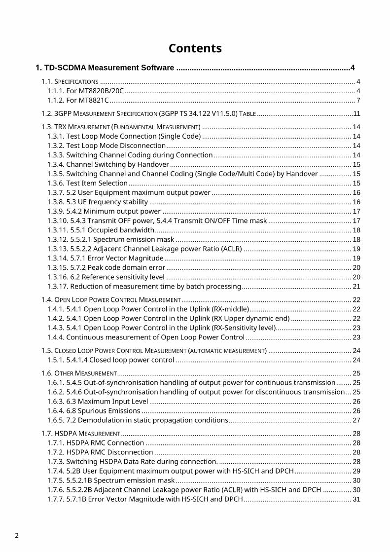
1.1.2. For MT8821C Table 1.1.2-1 Specifications for MX882107C TD-SCDMA Measurement Software
Item Specifications
Electrical characteristics
Typical values (typ.) are only for reference and are not guaranteed.
Frequency/Modulation measurement
Frequency 350 to 2700 MHz For the frequencies below 500 MHz, only the
following range meets the specifications: 452.5 to 457.5 MHz (LTE OperatingBand31) Input level –30 to +35 dBm (Main1/2)
Carrier frequency accuracy ±(Set frequency ×Reference oscillator accuracy +10 Hz) Modulation accuracy
Residual vector error ≤2.5% (when Single Code is input)
Amplitude measurement
Frequency 350 to 2700 MHz For the frequencies below 500 MHz, only the
following range meets the specifications: 452.5 to 457.5 MHz (LTE OperatingBand31) Input level –70 to +35 dBm (Main1/2) Measurement accuracy ±0.5 dB (–30 to +35 dBm),
typ. ±0.3 dB (–30 to +35 dBm), ±0.7 dB (–55 to –30 dBm), ±0.9 dB (–70 to –55 dBm), 10 to 40°C after calibration
Linearity ±0.2 dB (–40 to 0 dB, ≥–50 dBm), ±0.4 dB (–40 to 0 dB, ≥–60 dBm), 400 to 6000 MHz
Measurement object DPCH, UpPCH
Occupied bandwidth Frequency 350 to 2700 MHz For the frequencies below 500 MHz, only the
following range meets the specifications: 452.5 to 457.5 MHz (LTE OperatingBand31) Input level –10 to +35 dBm (Main1/2)
Adjacent channel leakage power
Frequency 350 to 2700 MHz For the frequencies below 500 MHz, only the
following range meets the specifications: 452.5 to 457.5 MHz (LTE OperatingBand31) Input level –10 to +35 dBm (Main1/2) Measurement point ±1.6 MHz, ±3.2 MHz Measurement range ≥50 dB (±1.6 MHz),
≥55 dB (±3.2 MHz)

8
Table 1.1.2-1 Specifications for MX882107C TD-SCDMA Measurement Software(Cont’d)
Item Specifications
RF signal generator Output frequency 300 to 2700 MHz (1 Hz steps) Channel level (DPCH) –30.0 to 0.0 dB (0.1 dB steps, Relative level with Ior
(Total power)) Channel level accuracy ±0.2 dB (Relative level accuracy with Ior) AWGN level Off, –20 to +5 dB (0.1 dB steps,
Relative level with Ior (Total power)) AWGN level accuracy ±0.2 dB (Relative level accuracy with Ior)
Error rate measurement
Function Applying PN9 or PN15 pattern to DTCH Measurement item BER, BLER BER measurement object
Loop Back data applied to uplink DTCH BLER measurement object
Loop Back data applied to uplink DTCH
Call processing Call control Location registration, call origination, call termination, hand-over, network-side release, UE-side release (Execution of the operation conforming to the 3GPP standard and pass/fail judgement can be performed.)
UE Control Output level, loopback (UE control conforming to the 3GPP standard can be performed.)

9
Table 1.1.2-2 Specifications for MX882107C-011 TD-SCDMA HSDPA Measurement Software
Item Specifications
Function RF tests (Rx measurement) related to HSDPA
Reference channel Transferring RMC 0.5Mbps UE Class (QPSK), RMC 1.1Mbps UE Class (QPSK), RMC 1.1Mbps UE Class (16QAM), RMC 1.6Mbps UE Class (QPSK), RMC 1.6Mbps UE Class (16QAM), RMC 2.2Mbps UE Class (QPSK), RMC 2.2Mbps UE Class (16QAM), RMC 2.8Mbps UE Class (QPSK), and RMC 2.8Mbps UE Class (16QAM)
Throughput measurement
Function Throughput measurement using RMC Measurement item Throughput Measurement object ACK and NACK applied to HS-SICH
CQI measurement Measurement object Periodically reported CQI (RTBS, RMF) value applied to HS-SICH
Call processing Call control: Location registration, Call processing using RMC (Execution of the operation conforming to the 3GPP standard and pass/fail judgment can be performed.)
UE control Output level (UE control conforming to the 3GPP standard can be performed.)
Table 1.1.2-3 Specifications for MX882107C-012 TD-SCDMA HSDPA Evolution Measurement Software
Item Specifications
Function RF tests (Rx measurement) related to HSDPA Evolution
Reference channel Transferring RMC Category 16-18UE(64QAM), RMC Category 19-21UE(64QAM), RMC Category 22-24UE(64QAM), RMC Category 18 Max, RMC Category 21 Max, and RMC Category 24 Max,
Throughput measurement
Function Throughput measurement using RMC Measurement item Throughput Measurement object ACK and NACK applied to HS-SICH
CQI measurement Measurement object Periodically reported CQI (RTBS) value applied to HS-SICH
Call processing Call control: Location registration, Call processing using RMC (Execution of the operation conforming to the 3GPP standard and pass/fail judgment can be performed.)
UE control Output level (UE control conforming to the 3GPP standard can be performed.)
10
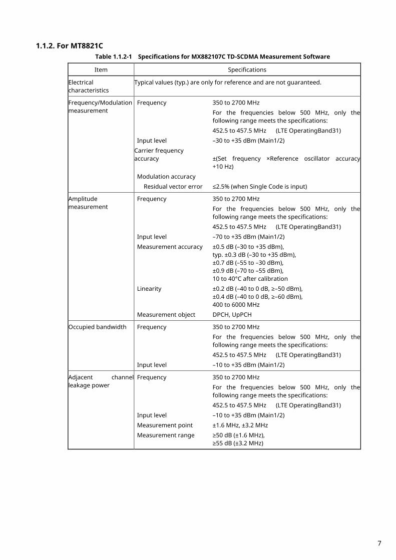
Table 1.1.2-4 Specifications for MX882107C-021 TD-SCDMA HSUPA Measurement Software
Item Specifications
Function RF tests (Tx measurement) related to HSUPA
Modulation measurement
This item depends on the MX882107C’s performance.
Call processing Call control Location registration, Call processing using FRC1, FRC2 (Execution of the operation conforming to the 3GPP standard and pass/fail judgment can be performed.)
UE control Output level (UE control conforming to the 3GPP standard can be performed.)

11
1.2. 3GPP Measurement Specification (3GPP TS 34.122 V11.5.0) Table
Item Comment
5 Transmitter Characteristics 5.2 User Equipment maximum output power √√ 5.2A User Equipment maximum output power with E-DCH MX882007C-021
MX882107C-021 √√
5.2B User Equipment maximum output power with HS-SICH and DPCH
MX882007C-011 MX882107C-011
√√
5.3 UE frequency stability √√ 5.4 Output Power Dynamics 5.4.1.3 Open loop power control √√ 5.4.1.4 Closed loop power control √√ 5.4.2 Minimum output power √√ 5.4.3 Transmit OFF power √√ 5.4.4 Transmit ON/OFF Time mask √√ 5.4.5 Out-of-synchronisation handling of output power for
continuous transmission √√
5.4.6 Out-of-synchronisation handling of output power for discontinuous transmission
√√
5.5 Output RF spectrum emissions 5.5.1 Occupied bandwidth √√ 5.5.2 Out of band emission 5.5.2.1 Spectrum emission mask √√ 5.5.2.1A Spectrum emission mask MX882007C-021
MX882107C-021 √√
5.5.2.1B Spectrum emission mask MX882007C-011 MX882107C-011
√√
5.5.2.2 Adjacent Channel Leakage power Ratio (ACLR) √√ 5.5.2.2A Adjacent Channel Leakage power Ratio (ACLR) with E-DCH MX882007C-021
MX882107C-021 √√
5.5.2.2B Adjacent Channel Leakage power Ratio (ACLR) with HS-SICH and DPCH
MX882007C-011 MX882107C-011
√√
5.5.3 Spurious Emissions Requires SPA √ 5.6 Transmit Intermodulation Requires SG and SPA √ 5.7 Transmit Modulation 5.7.1 Error Vector Magnitude √√ 5.7.1A Error Vector Magnitude with E-DCH 16QAM MX882007C-021
MX882107C-021 √√
5.7.1B Error Vector Magnitude with HS-SICH and DPCH MX882007C-011 MX882107C-011
√√
5.7.2 Peak code domain error √√ 6 Receiver Characteristics 6.2 Reference sensitivity level √√ 6.3 Maximum Input Level √√ 6.3A Maximum Input Level for HS-PDSCH Reception (16QAM) MX882007C-011
MX882107C-011 √√
6.4 Adjacent Channel Selectivity (ACS) Requires SG √ 6.5 Blocking Characteristics Requires SG √ 6.6 Spurious Response Requires SG √ 6.7 Intermodulation Characteristics Requires SG √ 6.8 Spurious Emissions Requires SPA √ 7 Performance Requirements 7.2 Demodulation in static propagation conditions Requires SG √ 7.3 Demodulation of DCH in multipath fading conditions 7.3.1 Multipath fading Case 1 Requires Fading √

12
Simulator and SG 7.3.2 Multipath fading Case 2 Requires Fading
Simulator and SG √
7.3.3 Multipath fading Case 3 Requires Fading Simulator and SG
√
7.5 Power control in downlink Requires Fading Simulator and SG
√
9 Performance requirements for HSDPA 9.3 Performance Requirements for 1.28 Mcps TDD option 9.3.1 HS-DSCH Throughput for Fixed Reference Channels 9.3.1A HS-DSCH throughput for Fixed Reference Channels 0.5 Mbps
UE class QPSK MX882007C-011 MX882107C-011 Requires Fading Simulator
√
9.3.1B HS-DSCH throughput for Fixed Reference Channels 1.1 Mbps UE class 16QAM
MX882007C-011 MX882107C-011 Requires Fading Simulator
√
9.3.1C HS-DSCH throughput for Fixed Reference Channels 1.6 Mbps UE class QPSK/16QAM
MX882007C-011 MX882107C-011 Requires Fading Simulator
√
9.3.1D HS-DSCH throughput for Fixed Reference Channels 2.2 Mbps UE class QPSK/16QAM
MX882007C-011 MX882107C-011 Requires Fading Simulator
√
9.3.1E HS-DSCH throughput for Fixed Reference Channels 2.8 Mbps UE class QPSK/16QAM
MX882007C-011 MX882107C-011 Requires Fading Simulator
√
9.3.2 HS-DSCH Throughput for Variable Reference Channels 9.3.2A HS-DSCH throughput for Variable Reference Channels 0.5
Mbps UE class MX882007C-011 MX882107C-011 Requires Fading Simulator
√
9.3.2B HS-DSCH throughput for Variable Reference Channels 1.1 Mbps UE class
MX882007C-011 MX882107C-011 Requires Fading Simulator
√
9.3.2C HS-DSCH throughput for Variable Reference Channels 1.6 Mbps UE class
MX882007C-011 MX882107C-011 Requires Fading Simulator
√
9.3.2D HS-DSCH throughput for Variable Reference Channels 2.2 Mbps UE class
MX882007C-011 MX882107C-011 Requires Fading Simulator
√
9.3.2E HS-DSCH throughput for Variable Reference Channels 2.8 Mbps UE class
MX882007C-011 MX882107C-011 Requires Fading Simulator
√
9.3.3 Reporting of HS-DSCH Channel Quality Indicator 9.3.3A Reporting of HS-DSCH Channel Quality Indicator-0.5 Mbps UE
class MX882007C-011 MX882107C-011 Requires Fading Simulator
√

13
9.3.3B Reporting of HS-DSCH Channel Quality Indicator-1.1 Mbps UE class
MX882007C-011 MX882107C-011 Requires Fading Simulator
√
9.3.3C Reporting of HS-DSCH Channel Quality Indicator-1.6 Mbps UE class
MX882007C-011 MX882107C-011 Requires Fading Simulator
√
9.3.3D Reporting of HS-DSCH Channel Quality Indicator-2.2 Mbps UE class
MX882007C-011 MX882107C-011 Requires Fading Simulator
√
9.3.3E Reporting of HS-DSCH Channel Quality Indicator-2.8 Mbps UE class
MX882007C-011 MX882107C-011 Requires Fading Simulator
√
9.3.4 HS-SCCH Detection Performance MX882007C-011 MX882107C-011 Requires Fading Simulator
√
11 Performance Requirement (E-DCH) 11.1 Detection of E-DCH HARQ ACK Indicator Channel (E-HICH) MX882007C-021
MX882107C-021 Requires Fading Simulator
√
11.2 Demodulation of E-DCH Absolute Grant Channel (E-AGCH) MX882007C-021 MX882107C-021 Requires Fading Simulator
√
√√: Support | √: Requires external equipment (SPA or SG) | F: Future Support | –: Not Support

14
1.3. TRX Measurement (Fundamental Measurement) Hereafter, control software is presupposed created by GPIB. See operation manual for details of GPIB commands and manual operations. GPIB commands are written in red. UE power class is presupposed 2.
1.3.1. Test Loop Mode Connection (Single Code) Measurement is performed by connecting to Test Loop Mode1. The connection procedures are below. Start from step 4 when location registration is already executed.
1. Execute PRESET to set default parameter. 2. Turn on UE power. 3. Execute CALLSTAT? and wait until the response becomes 2(=Idle(Regist)). 4. Execute CALLSA to connect to Test Loop Mode1. 5. Execute CALLSTAT? and wait until the response becomes 7(=Test Loop Mode).
Call Status can be confirmed using CALLSTATIC?. The confirmation procedures using CALLSTATIC? are below.
1. Execute PRESET to set default parameter. 2. Turn on UE power. 3. Execute CALLSTATIC? to check Call Status. When Call Status will be 2(=Idle(Regist)), the response will be
returned. 4. Execute CALLSA to connect to Test Loop Mode1. 5. Execute CALLSTATIC? to check Call Status. When Call Status will be 7(=Test Loop Mode), the response will be
returned.
1.3.2. Test Loop Mode Disconnection
1. Execute CALLSO to disconnect from Test Loop Mode1. 2. Execute CALLSTAT? and wait until the response becomes 2(=Idle(Regist)).
The confirmation procedures using CALLSTATIC? are below.
1. Execute CALLSO to disconnect from Test Loop Mode1. 2. Execute CALLSTATIC? to check Call Status. When Call Status will be 2(=Idle(Regist)), the response will be
returned.
1.3.3. Switching Channel Coding during Connection Channel Coding can be switched during Connection. The switching procedures are below.
1. Connect to Test Loop Mode1. 2. Execute CHCODING RMC_SINGLE to set Channel Coding to RMC (Single Code). 3. Execute TRX measurement. 4. Execute CHCODING RMC_MULTI to set Channel Coding to RMC (Multi Code). 5. Execute TRX measurement.

15
1.3.4. Channel Switching by Handover Measurement is normally performed at three frequency points (L, M and H). Channel can be switched quickly without reconnection by changing it at handover. Output Level must be set higher to avoid failing handover. Also, the GPIB commands, which transmitted during handover, stand by until the handover ends.
1. Execute TRX measurement at L channel. 2. Execute CHAN 10087 to handover to M channel. 3. Execute TRX measurement. 4. Execute CHAN 10121 to handover to H channel. 5. Execute TRX measurement.
1.3.5. Switching Channel and Channel Coding (Single Code/Multi Code) by Handover Measurement is normally performed at three frequency points (L, M and H) and Channel Coding (Single Code or Multi Code). Channel and Channel Coding can be switched quickly without reconnection by changing it at handover. Output Level must be set higher to avoid failing handover. Also, the GPIB commands, which transmitted during handover, stand by until the handover ends.
1. Execute HO 10053, RMC_SINGLE to handover to L channel and Single Code. 2. Execute TRX measurement. 3. Execute HO 10053, RMC_MULTI to handover to L channel and Multi Code. 4. Execute TRX measurement. 5. Execute HO 10087, RMC_SINGLE to handover to M channel and Single Code. 6. Execute TRX measurement. 7. Execute HO 10087, RMC_MULTI to handover to M channel and Multi Code. 8. Execute TRX measurement. 9. Execute HO 10121, RMC_SINGLE to handover to H channel and Single Code.
10. Execute TRX measurement. 11. Execute HO 10121, RMC_MULTI to handover to H channel and Multi Code. 12. Execute TRX measurement.
1.3.6. Test Item Selection All measurement items are turned on in the default setting of this instrument. In order to reduce measurement time, unnecessary items, such as BER and BLER measurements, should be turned off (BER_MEAS OFF, BLER_MEAS OFF) before measurement. All measurement items can be turned off when setting ALLMEASITEMS_OFF.

16
1.3.7. 5.2 User Equipment maximum output power
1. Connect to Test Loop Mode1. 2. Execute CHCODING RMC_SINGLE to set Channel Coding to RMC (Single Code). 3. Execute TESTPRM CALL_MAXPWR to set Test Parameter to Call – Maximum Output Power. 4. Wait until UE power reaches the maximum. 5. Execute PWR_AVG 20 to set the average count of power measurement at 20 times. 6. Execute SWP to perform power measurement. 7. Execute AVG_POWER? to read the power measurement result. 8. Check the measurement result is +24 dBm(+1.7 dB/-3.7 dB). 9. Execute CHCODING RMC_MULTI to set Channel Coding to RMC (Multi Code).
10. Execute SWP to perform power measurement. 11. Execute AVG_POWER? to read power measurement result. 12. Check the measurement result is +21 dBm(+1.7 dB/-3.7 dB).
TX Power corresponds to Mean Power (2MHz band).
1.3.8. 5.3 UE frequency stability
1. Connect to Test Loop Mode1. 2. Execute CHCODING RMC_SINGLE to set Channel Coding to RMC (Single Code). 3. Execute TESTPRM CALL_BERSENS to set Test Parameter to Call – BER (Reference Sensitivity Level). 4. Wait until UE power reaches the maximum. 5. Execute FREQ_AVG 200 to set the average count of Frequency measurement at 200 times. 6. Execute SWP to perform Frequency measurement. 7. Execute MAXABS_CARRFERR? PPM to read Frequency Error measurement result. 8. Check the measurement result is lower than (0.1 ppm + 10 Hz).

17
1.3.9. 5.4.2 Minimum output power
1. Connect to Test Loop Mode1. 2. Execute CHCODING RMC_SINGLE to set Channel Coding to RMC (Single Code). 3. Execute TESTPRM CALL_MINPWR to set Test Parameter to Call – Minimum Output Power. 4. Wait until UE power reaches the minimum. 5. Execute PWR_AVG 20 to set the average count of power measurement at 20 times. 6. Execute SWP to perform Power measurement. 7. Execute AVG_POWER? to read the measurement result. 8. Check the measurement result is lower than -48 dBm.
1.3.10. 5.4.3 Transmit OFF power, 5.4.4 Transmit ON/OFF Time mask
1. Connect to Test Loop Mode1. 2. Execute CHCODING RMC_SINGLE to set Channel Coding to RMC (Single Code). 3. Execute TESTPRM CALL_OFFPWR to set Test Parameter to Call – Off Power. 4. Wait until UE power reaches the maximum. 5. Execute PWRTEMP_AVG 20 to set the average count of Power Template measurement at 20 times. 6. Execute SWP to perform Power Template measurement. 7. Execute POWERPASS? to read Power Template measurement result. 8. Check the measurement result is PASS.
Transmit OFF Power is measured with lower Input Level to avoid the effect of floor noise. Although the measurement status is Level Over, it does not affect the measurement result.

18
1.3.11. 5.5.1 Occupied bandwidth
1. Connect to Test Loop Mode1. 2. Execute CHCODING RMC_SINGLE to set Channel Coding to (Single Code). 3. Execute TESTPRM CALL_MAXPWR to set Test Parameter to Call – Maximum Output Power. 4. Wait until UE power reaches the maximum. 5. Execute OBW_AVG 20 to set the average count of OBW measurement at 20 times. 6. Execute SWP to perform OBW measuremen. 7. Execute OBW? to read OBW measurement result. 8. Check the measurement result is lower than 1.6MHz.
1.3.12. 5.5.2.1 Spectrum emission mask
1. Connect to Test Loop Mode1. 2. Execute CHCODING RMC_SINGLE to set Channel Coding to (Single Code). 3. Execute TESTPRM CALL_MAXPWR to set Test Parameter to Call – Maximum Output Power. 4. Wait until UE power reaches the maximum. 5. Execute SMASK_AVG 20 to set the average count of SEM measurement at 20 times. 6. Execute SWP to perform SEM measurement. 7. Execute SMASKPASS? to read SEM measurement result. 8. Check the measurement result is PASS.
19
1.3.13. 5.5.2.2 Adjacent Channel Leakage power Ratio (ACLR)
1. Connect to Test Loop Mode1. 2. Execute CHCODING RMC_SINGLE to set Channel Coding to (Single Code). 3. Execute TESTPRM CALL_MAXPWR to set Test Parameter to Call – Maximum Output Power. 4. Wait until UE power reaches the maximum. 5. Execute ADJ_AVG 20 to set the average count of ACLR measurement at 20 times. 6. Execute SWP to perform ACLR measurement. 7. Execute AVG_MODPWR? LOW16; AVG_MODPWR? UP16 to read ACLR measurement result. 8. Check the measurement result is lower than -32.2 dB. 9. Execute AVG_MODPWR? LOW32; AVG_MODPWR? UP32 to read ACLR measurement result.
10. Check the measurement result is lower than -42.2 dB.
1.3.14. 5.7.1 Error Vector Magnitude
1. Connect to Test Loop Mode1. 2. Execute CHCODING RMC_SINGLE to set Channel Coding to (Single Code). 3. Execute TESTPRM CALL_20DBM to set Test Parameter to Call – EVM & PCDE@-20 dBm. 4. Wait until UE power reaches -20 dBm. 5. Execute MOD_AVG 20 to set the average count of Modulation Analysis measurement at 20 times. 6. Execute SWP to perform Modulation Analysis measurement. 7. Execute AVG_EVM? to read EVM measurement result. 8. Check the measurement result is lower than 17.5%.

20
1.3.15. 5.7.2 Peak code domain error
1. Connect to Test Loop Mode1. 2. Execute CHCODING RMC_MULTI to set Channel Coding to RMC (Multi Code). 3. Execute TESTPRM CALL_20DBM to set Test Parameter to Call – EVM & PCDE@-20 dBm. 4. Wait until UE power reaches -20 dBm. 5. Execute PCDE_AVG 20 to set the average count of Peak Code Domain Error measurement at 20 times. 6. Execute SWP to perform Peak Code Domain Error measurement. 7. Execute AVG_PCDERR? to read Peak Code Domain Error measurement result. 8. Check the measurement result is lower than -20 dB.
1.3.16. 6.2 Reference sensitivity level
1. Connect to Test Loop Mode1. 2. Execute CHCODING RMC_SINGLE to set Channel Coding to (Single Code). 3. Execute TESTPRM CALL_BERSENS to set Test Parameter to Call – BER (Reference Sensitivity Level). 4. Wait until UE power reaches the maximum. 5. Execute BER_SAMPLE 10000 to set the number of BER measurement samples at 10000 bits. 6. Execute SWP to perform BER measurement. 7. Execute BER? to read BER measurement result. 8. Check the measurement result is lower than 0.001.

21
1.3.17. Reduction of measurement time by batch processing Measuring time can be reduced by measuring same parameter items at once. [Maximum Output Power, OBW, ACLR, SEM]
1. Connect to Test Loop Mode1. 2. Execute CHCODING RMC_SINGLE to set Channel Coding to (Single Code). 3. Execute ALLMEASITEMS ON,20,ON,20,ON,200,ON,20,ON,20,ON,20,ON,20,ON,20,ON,OFF to turn on
measurements (excluding BLER), to set the average count of Frequency Error measurement at 200 times, to set the average count of other measurements at 20 times.
4. Execute TESTPRM CALL_MAXPWR to set Test Parameter to Call – Maximum Output Power. 5. Wait until UE power reaches the maximum. 6. Execute SWP to perform measurement. 7. Execute AVG_POWER? to read Power measurement result. 8. Execute OBW? to read OBW measurement result. 9. Execute AVG_MODPWR? LOW16; AVG_MODPWR? UP16 to read ACLR measurement result.
10. Execute AVG_MODPWR? LOW32; AVG_MODPWR? UP32 to read ACLR measurement result. 11. Execute SMASKPASS? to read SEM measurement result. [Frequency Error, BER] 12. Execute TESTPRM CALL_BERSENS to set Test Parameter to Call – BER (Reference Sensitivity Level). 13. Execute BER_SAMPLE 10000 to set the number of BER measurement samples at 10000 bits. 14. Execute SWP to perform measurement. 15. Execute MAXABS_CARRFERR? PPM to read Frequency Error measurement result. 16. Execute BER? to read BER measurement result. [Transmit ON/OFF Time mask] 17. Execute TESTPRM CALL_OFFPWR to set Test Parameter to Call – Off Power. 18. Execute SWP to perform measurement. 19. Execute POWERPASS? to read Power Template measurement result. [Minimum Output Power] 20. Execute TESTPRM CALL_MINPWR to set Test Parameter to Call – Minimum Output Power. 21. Wait until UE power reaches the minimum. 22. Execute SWP to perform measurement. 23. Execute AVG_POWER? to read Power measurement result. [EVM] 24. Execute TESTPRM CALL_20DBM to set Test Parameter to Call – EVM & PCDE@-20 dBm. 25. Wait until UE power reaches -20 dBm. 26. Execute SWP to perform measurement. 27. Execute AVG_EVM? to read EVM measurement result. [PCDE (Multi Code)] 28. Execute OLVL –66.0 to set Output Level at -66.0 dBm. 29. Execute CHCODING RMC_MULTI to set Channel Coding to RMC(Multi Code). 30. Execute OLVL -93.0 to set Output Level to –93.0 dBm. 31. Execute SWP to perform measurement. 32. Execute AVG_PCDERR? to read Peak Code Domain Error measurement result. [Maximum Output Power (Multi Code)] 33. Execute TESTPRM CALL_MAXPWR to set Test Parameter to Call – Maximum Output Power. 34. Wait until UE power reaches the maximum. 35. Execute SWP to perform measurement. 36. Execute AVG_POWER? to read Power measurement result.

22
1.4. Open Loop Power Control Measurement The following measurements are performed by setting Measurement Object of Fundamental Measurement Parameter to Open Loop Power Control.
1. Execute MEASOBJ OLPC to set Measurement Object to Open Loop Power Control. 2. Execute MAXULPWR 24 to set Maximum Allowed UL TX Power at 24 dBm. 3. Execute RABCONNECT OFF to turn off RAB Connection.
Maximum Allowed UL TX Power is the basic parameter of Cell Selection and Reselection. UE Power Class must be set lower than Maximum Tx Power, so the UE can perform Cell Selection and Reselection using Sensitivity Level. For example, when Power Class is 2, MAXULPWR should be 24. The call status can be returned to Idle in Test Loop Mode without connecting RAB by turning off RAB Connection so measurement is faster.
1.4.1. 5.4.1 Open Loop Power Control in the Uplink (RX-middle)
1. Execute TESTPRM IDLE_MIDDLE to set Test Parameter to Idle – RX middle. 2. Turn on UE power to perform Registration. 3. Execute SWPANDPG to perform UpPCH measurement in Test Loop Mode. 4. Execute UPPCHPWR? to read Power measurement result of UpPCH. 5. Check the measurement result is -10 dBm(+/-10 dB).
1.4.2. 5.4.1 Open Loop Power Control in the Uplink (RX Upper dynamic end)
1. Execute TESTPRM IDLE_UPPER to set Test Parameter to Idle – RX Upper Dynamic End. 2. Turn on UE power to perform Registration. 3. Execute SWPANDPG to perform UpPCH measurement in Test Loop Mode. 4. Execute UPPCHPWR? to read Power measurement result of UpPCH. 5. Check the measurement result is -25 dBm(+/-10 dB).

23
1.4.3. 5.4.1 Open Loop Power Control in the Uplink (RX-Sensitivity level)
1. Execute TESTPRM IDLE_SENS to set Test Parameter to Idle – RX Sensitivity Level. 2. Turn on UE power to perform Registration. 3. Execute SWPANDPG to perform UpPCH measurement in Test Loop Mode. 4. Execute UPPCHPWR? to read Power measurement result of UpPCH. 5. Check the measurement result is +9 dBm(±10 dB).
1.4.4. Continuous measurement of Open Loop Power Control Although Open Loop Power Control measurement is performed by changing Primary CCPCH TX Power and PRXUpPCHdes, these parameters are for broadcast information use and are not reflected at UE side immediately after the change. In order to perform Open Loop Power Control measurement continuously, the parameters must be reflected at UE by any of the following methods.
1) Wait about 5 seconds after changing parameters. When changing parameters, the instrument transmits BCCH modification info to UE with PAGING TYPE1 message. However, it takes about 5 seconds until the parameters are reflected on UE side.
2) After changing parameters, turn on UE power again, and wait until UE performs Registration.
3) Change LAC parameter along with the above parameter, and wait until UE performs Registration.
The LAC value can be incremented when performing LACINC.
24
1.5. Closed Loop Power Control Measurement (automatic measurement)
1.5.1. 5.4.1.4 Closed loop power control
1. Connect to Test Loop Mode1. 2. Execute TESTPRM CALL_CLPC to set Test Parameter to Call – Closed Loop Power Control. 3. Execute CLPC_MEAS AUTO_ALL to set CLPC Measurement Method to Auto(Step All). 4. Execute SWP to perform measurement. 5. Execute CLPC_PASS? ALL and check the measurement result is PASS.
25
1.6. Other Measurement
1.6.1. 5.4.5 Out-of-synchronisation handling of output power for continuous transmission
1. Execute TESTPRM IDLE_OSYNC_SET to set Test Parameter to Idle – Out-of-Sync. Idle Setting. 2. Turn on UE power to perform Registration. 3. Connect to Test Loop Mode1. 4. Execute TESTPRM CALL_OSYNC_CONT to set Test Parameter to Call – Out-of-Sync. Continuous. 5. Execute SWP to perform Power measurement. 6. Execute OUTSYNC_PASS? ALL and check the measurement result is PASS.
1.6.2. 5.4.6 Out-of-synchronisation handling of output power for discontinuous transmission
1. Execute TESTPRM IDLE_OSYNC_SET to set Test Parameter to Idle – Out-of-Sync. Idle Setting. 2. Turn on UE power to perform Registration. 3. Connect to Test Loop Mode1. 4. Execute TESTPRM CALL_OSYNC_DISC to set Test Parameter to Call – Out-of-Sync. Discontinuous. 5. Execute SWP to perform Power measurement. 6. Execute OUTSYNC_PASS? ALL and check the measurement result is PASS.

26
1.6.3. 6.3 Maximum Input Level
1. Connect to Test Loop Mode1. 2. Execute TESTPRM CALL_BERMAX to set Test Parameter to Call – BER (Maximum Input Level). 3. Execute BER_SAMPLE 10000 to set the number of BER measurement samples at 10000 bit. 4. Execute SWP to perform BER measurement. 5. Execute BER? to read BER measurement result. 6. Check the measurement result is lower than 0.001.
1.6.4. 6.8 Spurious Emissions
1. Execute RRCSTATE CELLFACH to set RRC State to CELL_FACH. 2. Execute SINTRASCHSW ON to turn on Sintrasearch. 3. Execute SINTERSCHSW ON to turn on Sintersearch. 4. Execute SSCHRATSW ON to turn on Ssearch,RAT. 5. Execute MAXULPWR 24 to set Maximum Allowed UL TX Power to 24dBm. 6. Turn on UE power to perform Registration. 7. Execute OLVL -52.0 to set Output Level to -52.0dBm. 8. Execute AWGNLVL ON to turn on AWGN output. 9. Execute AWGNPWR -9.0 to set Ior/Ioc to 9.0dB.
10. Execute PCCPCHLVL -3.0 to set PCCPCH Ec/Ior to -3.0dB. 11. Execute DWPCHLVL 0.0 to set DwPCH Ec/Ior to 0.0dB. 12. Execute CALLSA, UE becomes to CELL_FACH state. 13. It is possible to measure Spurious Emissions with an external Spectrum Analyzer.

27
1.6.5. 7.2 Demodulation in static propagation conditions [Test1]
1. Execute TESTMODE MODE2 to set Test Loop Mode to Mode2. When UE does not support Test Loop Mode2, execute TESTMODE MODE1AM to set Test Loop Mode to Test Mode1(AM).
2. Execute CHCODING RMC_SINGLE to set Channel Coding to RMC (Single Code). 3. Connect to Test Loop Mode. 4. Execute OLVL -56.1 to set Output Level at -56.1 dBm. 5. Execute AWGNLVL ON to turn on AWGN output. 6. Execute AWGNPWR -3.9 to set Ior/Ioc at -3.9 dB. 7. Execute DDPCHPWR -7.0 to set DPCH_Ec/Ior at -7.0 dB. 8. Execute ALLMEASITEMS OFF,1,OFF,1,OFF,1,OFF,1,OFF,1,OFF,1,OFF,1,OFF,1,OFF,ON to turn on only BLER
measurement. 9. Execute BLER_SAMPLE 1000 to set the number of BLER measurement samples at 1000 block.
10. Execute SWP to perform BLER measurement. 11. Execute BLER? to read BLER measurement result. 12. Check the measurement result is lower than 0.01.
28
1.7. HSDPA Measurement Hereafter, control software is assumed to be created by GPIB. See the operation manual for details of GPIB commands and manual operations. GPIB commands are in red.
1.7.1. HSDPA RMC Connection When connecting with HSDPA, Location registration must be performed using PS. Set Registration Mode to Combined or CS&PS, and connect at HSDPA RMC.
1. Execute PRESET to set the default parameters. 2. Execute REGMODE COMBINED to set Registration Mode to Combined. 3. Execute CHCODING HSDPA_RMC to set Channel Coding to HSDPA RMC. 4. Turn on the UE power. 5. Execute CALLSTAT? and wait until the response becomes 2 (= Idle (Regist)). 6. Execute CALLSA to perform HSDPA RMC connection. 7. Execute CALLSTAT? and wait until the response becomes 6 (= Communication).
Call Status can be confirmed using CALLSTATIC?. The confirmation procedures using CALLSTATIC? are below.
1. Execute PRESET to set the default parameters. 2. Execute REGMODE COMBINED to set Registration Mode to Combined. 3. Execute CHCODING HSDPA_RMC to set Channel Coding to HSDPA RMC. 4. Turn on the UE power. 5. Execute CALLSTATIC? to check Call Status. When Call Status becomes 2(=Idle(Regist)), the response is
returned. 6. Execute CALLSA to perform HSDPA RMC connection. 7. Execute CALLSTATIC? to check Call Status. When Call Status becomes 6(=Communication), the response is
returned.
1.7.2. HSDPA RMC Disconnection
1. Execute CALLSO to disconnect from HSDPA RMC. 2. Execute CALLSTAT? and wait until the response becomes 2(=Idle(Regist)).
The confirmation procedures using CALLSTATIC? are below.
1. Execute CALLSO to disconnect from HSDPA RMC. 2. Execute CALLSTATIC? to check Call Status. When Call Status becomes 2(=Idle(Regist)), the response is
returned.
1.7.3. Switching HSDPA Data Rate during connection. HSDPA Data Rate can be switched during Connection. The switching procedures are below.
1. Connect to HSDPA RMC. 2. Execute HSRATE 0.5M_QPSK to set HSDPA Data Rate to 0.5 Mbps UE Class (QPSK). 3. Execute TRX measurement. 4. Execute HSRATE 1.1M_16QAM to set HSDPA Data Rate to 1.1 Mbps UE Class (16QAM). 5. Execute TRX measurement.
29
1.7.4. 5.2B User Equipment maximum output power with HS-SICH and DPCH
1. Execute HSTYPE FRC and set HSDPA Data Type to FRC. 2. Execute HSRATE 1.1M_16QAM and set HSDPA Data Rate to 1.1 Mbps UE Class (16QAM). 3. Execute TPCPAT ALT to set TPC Pattern to Alternate. 4. Connect at HSDPA RMC 5. Execute TPCPAT CLPC and set TPC Pattern to Closed Loop Power Control. 6. Execute ILVL 16.2 and set Input Level to 16.2 dBm. 7. Wait about 100ms until UE power reaches 16.2 dBm 8. Execute TPCPAT ALT and set TPC Pattern to Alternate 9. Execute ILVL 25.7 and set Input Level to 25.7 dBm
10. Execute TPCPAT ALL1 and set TPC Pattern to All 1. 11. Execute PWR_MEAS ON to set Power measurement to ON. 12. Execute PWR_AVG 20 to set the average Power measurement to 20 times. 13. Execute SWP to perform Power measurement. 14. Execute AVG_POWER? to read the Power measurement result. 15. Check the measurement result is +21.5 dBm (+4.2 dB/-3.7 dB).

30
1.7.5. 5.5.2.1B Spectrum emission mask
1. Execute HSTYPE FRC to set HSDPA Data Type to FRC. 2. Execute HSRATE 1.1M_16QAM to set HSDPA Data Rate to 1.1 Mbps UE Class (16QAM). 3. Perform call connection with HSDPA RMC. 4. Execute ILVL 30.0 to set Input Level to 30.0 dBm. 5. Execute TPCPAT ALL1 to set TPC Pattern to All1. 6. Wait until the UE reaches maximum power. 7. Execute SMASK_MEAS ON to set SEM measurement to ON. 8. Execute SMASK_AVG 20 to set the average SEM measurement to 20 times. 9. Execute SWP to perform SEM measurement.
10. Execute SMASKPASS? to read the SEM measurement result. 11. Check the measurement result is PASS.
1.7.6. 5.5.2.2B Adjacent Channel Leakage power Ratio (ACLR) with HS-SICH and DPCH 1. Execute HSTYPE FRC to set HSDPA Data Type to FRC. 2. Execute HSRATE 1.1M_16QAM to set HSDPA Data Rate to 1.1 Mbps UE Class (16QAM). 3. Perform call connection with HSDPA RMC. 4. Execute ILVL 30.0 to set Input Level to 30.0 dBm. 5. Execute TPCPAT ALL1 to set TPC Pattern to All1. 6. Wait until the UE reaches maximum power. 7. Execute ADJ_MEAS ON to set ACLR measurement to ON. 8. Execute ADJ_AVG 20 to set the average ACLR measurement to 20 times. 9. Execute SWP to perform ACLR measurement.
10. Execute MODPWRPASS? to read the Adjacent Channel Power measurement result. 11. Check the measurement result is PASS.

31
1.7.7. 5.7.1B Error Vector Magnitude with HS-SICH and DPCH
1. Execute HSTYPE FRC to set HSDPA Data Type to FRC. 2. Execute HSRATE 1.1M_16QAM to set HSDPA Data Rate to 1.1 Mbps UE Class (16QAM). 3. Perform call connection with HSDPA RMC. 4. Execute ILVL –20.0 to set Input Level to –20.0 dBm. 5. Execute TPCPAT CLPC to set TPC Pattern to Closed Loop Power Control. 6. Wait until the UE power becomes –20 dBm. 7. Execute MOD_MEAS ON to set Modulation Analysis measurement to ON. 8. Execute MOD_AVG 20 to set average Modulation Analysis measurement to 20 times. 9. Execute SWP to perform Modulation Analysis measurement.
10. Execute AVG_EVM? to read the EVM measurement result. 11. Check the measurement result is below 17.5%.
1.7.8. 6.3A Maximum Input Level for HS-PDSCH Reception (16QAM) 16. Execute HSTYPE FRC to set HSDPA Data Type to FRC. 17. Execute MAXHARQTX 1 to set Maximum number of HARQ transmissions to 1. 18. Execute RVCODINGALL 6,2,1,5 to set Redundancy and Constellation Version to 6, 2, 1, 5. 19. Connect at HSDPA RMC. 20. Execute HSRATE 1.1M_16QAM to set HSDPA Data Rate to 1.1 Mbps UE Class (16QAM). 21. Execute OLVL -25.0 to set Output Level to –25.0 dBm. 22. Execute TPUT_MEAS ON to set HSDPA Throughput measurement to On. 23. Execute TPUT_TYPE TPUT to set HSDPA Throughput Measurement Type to Throughput. 24. Execute TPUT_SAMPLE 10000 to set the number of HSDPA Throughput measurement samples to 10000
blocks. 25. Execute SWP to measure HSDPA Throughput. 26. Execute TPUT? to read the measured Throughput result. 27. Check the measured result is 500 kbps or more.

32
1.7.9. 9.3.3 Reporting of HS-DSCH Channel Quality Indicator (2.8 Mbps UE) 1. Execute HSTYPE VRC to set HSDPA Data Type to VRC. 2. Execute MAXHARQTX 1 to set Maximum number of HARQ transmissions to 1. 3. Connect at HSDPA RMC. 4. Execute HSRATE 2.8M_QPSK to set HSDPA Data Rate to 2.8 Mbps UE Class (QPSK). 5. Execute HSPDSCHLVL -10.0 to set HS-PDSCH_Ec/Ior to -10.0dB. 6. Execute AWGNLVL ON to set AWGN Output to On. 7. Execute AWGNPWR -1 to set AWGN Level to -1 dB. 8. Execute OLVL -59.0 to set Output Level to -59.0 dBm. 9. Wait until UE output is stabilized.
10. Execute TPUT_MEAS ON to set HSDPA Throughput measurement to On. 11. Execute TPUT_TYPE CQI to set HSDPA Throughput Measurement Type to CQI. 12. Execute TPUT_SAMPLE 10000 to set the number of HSDPA Throughput measurement samples to 10000
blocks. 13. Execute CQI_MEAS ON to set CQI measurement to On. 14. Execute CQI_SAMPLE 2000 to set the number of CQI measurement samples to 2000 blocks. 15. Execute CQI_RANGE 2 to set CQI counting range to 2. 16. Execute SWP to measure HSDPA Throughput. 17. Execute TPUT_BLER? to read the measured Throughput result. 18. Check the measured result is 0.1 or less. 19. Execute CQI_SUM? to read the CQI measurement result. 20. Checkt the measured result is 1800 or more.
33
1.8. HSUPA Measurement Hereafter, control software is assumed to be created by GPIB. See the operation manual for details of GPIB commands and manual operations. GPIB commands are in red.
1.8.1. HSUPA RMC Connection When connecting with HSUPA, Location registration must be performed using PS. Set Registration Mode to Combined or CS&PS, and connect at HSUPA RMC.
1. Execute PRESET to set the default parameters. 2. Execute REGMODE COMBINED to set Registration Mode to Combined. 3. Execute CHCODING HSUPA_RMC to set Channel Coding to HSUPA RMC. 4. Turn on the UE power. 5. Execute CALLSTAT? and wait until the response becomes 2 (= Idle (Regist)). 6. Execute CALLSA to perform HSUPA RMC connection. 7. Execute CALLSTAT? and wait until the response becomes 7(=Loop Mode 1).
Call Status can be confirmed using CALLSTATIC?. The confirmation procedures using CALLSTATIC? are below. 1. Execute PRESET to set the default parameters. 2. Execute REGMODE COMBINED to set Registration Mode to Combined. 3. Execute CHCODING HSUPA_RMC to set Channel Coding to HSUPA RMC. 4. Turn on the UE power. 5. Execute CALLSTATIC? to check Call Status. When Call Status becomes 2(=Idle(Regist)), the response is
returned. 6. Execute CALLSA to perform HSUPA RMC connection. 7. Execute CALLSTATIC? to check Call Status. When Call Status becomes 7(=Loop Mode 1), the response is
returned.
1.8.2. HSUPA RMC Disconnection
1. Execute CALLSO to disconnect from HSUPA RMC. 2. Execute CALLSTAT? and wait until the response becomes 2(=Idle(Regist)).
The confirmation procedures using CALLSTATIC? are below.
1. Execute CALLSO to disconnect from HSUPA RMC. 2. Execute CALLSTATIC? to check Call Status. When Call Status becomes 2(=Idle(Regist)), the response is
returned.

34
1.8.3. 5.2A User Equipment maximum output power with E-DCH
1. Execute HSURATE FRC3 to set HSUPA Data Rate to FRC3. 2. Execute PERFROM_MEAS ON to set HSUPA Performance to On. 3. Execute PERFROM_SAMPLE 15 to set HSUPA Performance – Number of Sample to 15. 4. Perform call connection with HSUPA RMC. 5. Execute TPCPAT CLPC to set TPC Pattern to Closed Loop Power Control. 6. Execute ILVL 7.3 to set Input Level to 7.3 dBm. 7. Wait about 150 ms until UE power reaches 7.3 dBm. 8. Execute TPCPAT ALT to set TPC Pattern to Alternate. 9. Execute ILVL 25.7 to set Input Level to 25.7 dBm.
10. Execute SWP to perform HSUPA Performance measurement. Check the E-DCH TB Index measurement result is
53. 11. Execute TPC_CMD_UP to raise [TxPower] only 1 dB and wait 150 ms. 12. Execute SWP to perform HSUPA Performance measurement. 13. Execute AVE_TBI? to read the E-DCH TB Index measurement result, and confirm it is 53. 14. Repeat procedures 11 to 13 until the E-DCH TB Index measurement result is not 53. 15. Execute TPC_CMD_DOWN to reduce [TxPower] only 1 dB and wait 150 ms. 16. Execute SWP to perform HSUPA Performance measurement, and confirm the E-DCH TB Index measurement result
is 53. (Repeat procedures 15 and 16 if the E-DCH TB Index measurement result is not 53.)
17. Execute PWR_MEAS ON to set Power measurement to ON. 18. Execute PWR_AVG 20 to set average Power measurement to 20 times. 19. Execute SWP to perform Power measurement. 20. Execute AVG_POWER? to read the Power measurement result. 21. Check the measurement result is +22.5 dBm (+3.2 dB/–5.2 dB).
1.8.4. 5.5.2.1A Spectrum emission mask
1. Execute HSURATE FRC3 to set HSUPA Data Rate to FRC3. 2. Perform call connection with HSUPA RMC. 3. Execute ILVL 30.0 to set Input Level to 30.0 dBm. 4. Execute TPCPAT ALL1 to set TPC Pattern to All1. 5. Wait until the UE reaches maximum power. 6. Execute PWR_MEAS ON to set Power measurement to ON. 7. Execute PWR_AVG 20 to set average Power measurement to 20 times. 8. Execute SWP to perform Power measurement. 9. Execute SMASKPASS? to read the SEM measurement result.
10. Check the measurement result is PASS.

35
1.8.5. 5.5.2.2A Adjacent Channel Leakage power Ratio (ACLR) with E-DCH
1. Execute HSURATE FRC3 to set HSUPA Data Rate to FRC3. 2. Perform call connection with HSUPA RMC. 3. Execute ILVL 30.0 to set Input Level to 30.0 dBm. 4. Execute TPCPAT ALL1 to set TPC Pattern to All1. 5. Wait until the UE reaches maximum power. 6. Execute ADJ_MEAS ON to set ACLR measurement to ON. 7. Execute ADJ_AVG 20 to set average ACLR measurement to 20 times. 8. Execute SWP to perform ACLR measurement. 9. Execute MODPWRPASS? to read the Adjacent Channel Power measurement result.
10. Check the measurement result is PASS.
1.8.6. 5.7.1A Error Vector Magnitude with E-DCH 16QAM
1. Execute HSURATE FRC2 to set HSUPA Data Rate to FRC2. 2. Connect to HSUPA RMC. 3. Execute TESTPRM CALL_20DBM to set Test Parameter to Call – EVM & PCDE@-20 dBm. 4. Wait until UE power reaches -20 dBm. 5. Execute MOD_AVG 20 to set the average count of Modulation Analysis measurement to 20 times. 6. Execute EPUCH_MEAS_SLOT 4 to set E-PUCH Measurement Measurement Slot to 4. 7. Execute SWP to perform Modulation Analysis measurement. 8. Execute AVG_EVM? to read EVM measurement result. 9. Check the measurement result is lower than 14.0%.

36
1.8.7. 11.1 Detection of E-DCH HARQ ACK Indicator Channel (E-HICH) [Test1]
1. Execute EHICHPAT NACK to set E-HICH Pattern to NACK. 2. Execute OLVL -60.0 to set Output Level to -60.0dBm. 3. Execute AWGNLVL ON to turn on AWGN output. 4. Execute AWGNPWR 0.0 to set Ior/Ioc to 0dB. 5. Execute EHICHLVL -7.5 to set E-HICH Ec/Ior to -7.5dB. 6. Execute HSURATE FRC1_CAT3_6 to set HSUPA Data Rate to FRC1 (Category3-6). Execute HSURATE
FRC1_CAT1_2 to set to FRC1 (Category1-2) when UE E-DCH Category is 1 to 2. 7. Perform call connection with HSUPA RMC. 8. Execute ALLMEASITEMS_OFF to turn off all measurement items. 9. Execute PERFORM_MEAS ON to turn on HSUPA Performance measurement.
10. Execute PERFORM_SAMPLE 1000 to set the number of HSUPA Performance measurement samples at 1000 block.
11. Execute SWP to perform HSUPA Performance measurement. 12. Execute FALSE_ACK_NACK_PROB? EXP to read False ACK Probability measurement result. 13. Check the measurement result is lower than 2E-3. [Test2]
1. Execute EHICHPAT ACK to set E-HICH Pattern to ACK. 2. Execute OLVL –60.0 to set Output Level to -60.0dBm. 3. Execute AWGNLVL ON to turn on AWGN output. 4. Execute AWGNPWR 0.0 to set Ior/Ioc to 0.0dB. 5. Execute EHICHLVL -7.5 to set E-HICH Ec/Ior to -7.5dB. 6. Execute HSURATE FRC1_CAT3_6 to set HSUPA Data Rate to FRC1 (Category3-6). Execute HSURATE
FRC1_CAT1_2 to set to FRC1 (Category1-2) when UE E-DCH Category is 1 to 2. 7. Perform call connection with HSUPA RMC. 8. Execute ALLMEASITEMS_OFF to turn off all measurement items. 9. Execute PERFORM_MEAS ON to turn on HSUPA Performance measurement.
10. Execute PERFORM_SAMPLE 1000 to set the number of HSUPA Performance measurement samples at 1000 block.
11. Execute SWP to perform HSUPA Performance measurement. 12. Execute FALSE_ACK_NACK_PROB? EXP to read False NACK Probability measurement result. 13. Check the measurement result is lower than 2E-2.

37
1.8.8. 11.2 Demodulation of E-DCH Absolute Grant Channel (E-AGCH)
1. Execute HSURATE FRC1_CAT3_6 to set HSUPA Data Rate to FRC1 (Category3-6). When UE does not support FRC1 (Category3-6), execute HSURATE FRC1_CAT1_2 to set HSUPA Data Rate to FRC1 (Category1-2).
2. Execute EHICHPAT ACK to set E-HICH Pattern to ACK. 3. Execute ABSGNTVAL 31 to set E-AGCH Absolute Grant Value to 31. (*1) 4. Execute OLVL -51.4 to set Output Level to -51.4dBm. 5. Execute AWGNLVL ON to turn on AWGN output. 6. Execute AWGNPWR -8.6 to set Ior/Ioc to 8.6dB. 7. Execute EAGCHLVL -3.0 to set E-AGCH Ec/Ior to -3.0dB. 8. Connect to HSUPA RMC. 9. Execute ALLMEASITEMS_OFF to turn off all measurement items.
10. Execute PERFORM_MEAS ON to turn on HSUPA Performance measurement. 11. Execute PERFORM_SAMPLE 1000 to set the number of HSUPA Performance measurement samples to 1000
block. 12. Execute SWP to perform HSUPA Performance measurement. 13. Execute MISSED_DTCTN_PROB? EXP to read Missed E-AGCH Detection Probability measurement result. 14. Check the measurement result is lower than 0.01(1E-2). (*1): The PPR value is still "To be Defined" in the 3GPP standards but here it is set to 31.
1.9. UE Report Measurement Report can be sent to UE. The following explains how to acquire the report value of Primary CCPCH RSCP.
1. Connect to Test Loop Mode1. 2. Execute MEASREP ON to report Measurement Report to UE. 3. Execute CALLRFR to initialize UE Report value. 4. Execute PCCPCH_RSCP? FLAG. When response is 1, report is returned. 5. Execute PCCPCH_RSCP? to read P-CCPCH Ec/N0 value. 6. When reading Report value again, return to 3.
UE Report is updated at regular interval. When using PCCPCH_RSCP? 1 to 10, the latest updated value is returned after UE Report is updated for specified counts.
1. Connect to Test Loop Mode1. 2. Execute MEASREP ON to report Measurement Report to UE. 3. Execute OLVL -90.0 to set Output Level to -90.0 dBm. 4. Execute PCCPCH_RSCP? 3 to read P-CCPCH Ec/N0 value after UE Report is updated for three times.

38
1.10. Others
1.10.1. Calibration By using this function, level accuracy frequency between input level and output level can be set flat, and the level gap caused by internal temperature change can be calibrated. A single unit supports both Band Calibration (BANDCAL) and Full Calibration (FULLCAL). Band Calibration is performed at TD-SCDMA band. Full Calibration is performed at the input/output band of the unit (30~2700 MHz). Although Full Calibration includes the contents of the Band Calibration, it takes time. Full Calibration should be executed when the seasonal temperature changes greatly or software version is upgraded. In this case, aging must be executed for about 1 hour before calibration. Band Calibration should be executed so that calibration is performed without temperature change.

39
1.10.2. External Loss The unit supports setting of External Loss (such as cable loss) as offset values. External Loss is set at Main DL, Main UL and Aux.
An example of how to set Main DL Loss to 3.0 dB and Main UL Loss to 5.0 dB is shown below.
1. Execute DLEXTLOSSSW ON to set [External Loss(Main DL)] to [On]. 2. Execute ULEXTLOSSW ON to set [External Loss(Main UL)] to [On]. 3. Execute DLEXTLOSS 3.0 to set [External Loss(Main DL)] to [3.0] dB. 4. Execute ULEXTLOSS 5.0 to set [External Loss(Main UL)] to [5.0] dB.
Although the above commands can set only one loss value for all frequencies, up to 100 loss values can be set by using the GPIB and by setting an External Loss Table, which supports both W-CDMA and GSM. In this case, a frequency without a loss value is the table is compensated with next loss value. An example of how to set a 3.0 dB loss value for the 2140 MHz frequency, and a 5.0 dB loss value for the 1950 MHz frequency is shown below.
1. Execute DLEXTLOSSW COMMON to use the Main DL External Loss common table. 2. Execute ULEXTLOSSW COMMON to use the Main UL External Loss common table. 3. Execute LOSSTBLVAL 1950MHz, 0.0, 5.0, 0.0 to set the 1950 MHz Main UL Loss value to 5.0 dB. 4. Execute LOSSTBLVAL 2140MHz, 3.0, 0.0, 0.0 to set the 2140 MHz Main DL Loss value to 3.0 dB.
The number of frequency points specified in the table is displayed either in the on-screen External Loss Table, or can be read by executing LOSSTBLSAMPLE?. All loss values can be deleted by executing DELLOSSTBL. *The operation when setting External Loss differs according to the version. Sometimes, the I/O level may be changed unexpectedly when setting parameters at tracking operation. After setting the measurement conditions (external loss, frequency, etc.), always set the I/O level before starting measurement (W/G, TDS only) The specifications have been changed for version V20.00 and later so the I/O level does not change when changing the external loss and frequency settings.

Anritsu Company 1155 East Collins Blvd., Suite 100, Richardson, TX 75081, U.S.A.Toll Free: 1-800-267-4878Phone: +1-972-644-1777Fax: +1-972-671-1877
• CanadaAnritsu Electronics Ltd.700 Silver Seven Road, Suite 120, Kanata, Ontario K2V 1C3, CanadaPhone: +1-613-591-2003 Fax: +1-613-591-1006
• Brazil Anritsu Eletrônica Ltda.Praça Amadeu Amaral, 27 - 1 Andar01327-010 - Bela Vista - São Paulo - SP - BrazilPhone: +55-11-3283-2511Fax: +55-11-3288-6940
• MexicoAnritsu Company, S.A. de C.V.Av. Ejército Nacional No. 579 Piso 9, Col. Granada11520 México, D.F., MéxicoPhone: +52-55-1101-2370Fax: +52-55-5254-3147
• United KingdomAnritsu EMEA Ltd. 200 Capability Green, Luton, Bedfordshire, LU1 3LU, U.K.Phone: +44-1582-433200 Fax: +44-1582-731303
• FranceAnritsu S.A. 12 avenue du Québec, Bâtiment Iris 1- Silic 612,91140 VILLEBON SUR YVETTE, FrancePhone: +33-1-60-92-15-50Fax: +33-1-64-46-10-65
• GermanyAnritsu GmbHNemetschek Haus, Konrad-Zuse-Platz 1 81829 München, Germany Phone: +49-89-442308-0Fax: +49-89-442308-55
• ItalyAnritsu S.r.l.Via Elio Vittorini 129, 00144 Roma, ItalyPhone: +39-6-509-9711 Fax: +39-6-502-2425
• SwedenAnritsu ABKistagången 20B, 164 40 KISTA, SwedenPhone: +46-8-534-707-00Fax: +46-8-534-707-30
• FinlandAnritsu ABTeknobulevardi 3-5, FI-01530 VANTAA, FinlandPhone: +358-20-741-8100Fax: +358-20-741-8111
• DenmarkAnritsu A/SKay Fiskers Plads 9, 2300 Copenhagen S, DenmarkPhone: +45-7211-2200Fax: +45-7211-2210
• RussiaAnritsu EMEA Ltd. Representation Office in RussiaTverskaya str. 16/2, bld. 1, 7th floor.Moscow, 125009, RussiaPhone: +7-495-363-1694Fax: +7-495-935-8962
• SpainAnritsu EMEA Ltd. Representation Office in SpainEdificio Cuzco IV, Po. de la Castellana, 141, Pta. 828046, Madrid, SpainPhone: +34-915-726-761Fax: +34-915-726-621
• United Arab EmiratesAnritsu EMEA Ltd. Dubai Liaison OfficeP O Box 500413 - Dubai Internet CityAl Thuraya Building, Tower 1, Suit 701, 7th FloorDubai, United Arab EmiratesPhone: +971-4-3670352Fax: +971-4-3688460
• P.R. China (Shanghai)Anritsu (China) Co., Ltd.Room 2701-2705, Tower A, New Caohejing International Business CenterNo. 391 Gui Ping Road Shanghai, 200233, P.R. ChinaPhone: +86-21-6237-0898Fax: +86-21-6237-0899
• P.R. China (Hong Kong)Anritsu Company Ltd.Unit 1006-7, 10/F., Greenfield Tower, Concordia Plaza,No. 1 Science Museum Road, Tsim Sha Tsui East, Kowloon, Hong Kong, P.R. ChinaPhone: +852-2301-4980Fax: +852-2301-3545
• JapanAnritsu Corporation8-5, Tamura-cho, Atsugi-shi, Kanagawa, 243-0016 JapanPhone: +81-46-296-1221Fax: +81-46-296-1238
• KoreaAnritsu Corporation, Ltd.5FL, 235 Pangyoyeok-ro, Bundang-gu, Seongnam-si, Gyeonggi-do, 463-400 KoreaPhone: +82-31-696-7750Fax: +82-31-696-7751
• AustraliaAnritsu Pty. Ltd.Unit 21/270 Ferntree Gully Road, Notting Hill, Victoria 3168, AustraliaPhone: +61-3-9558-8177Fax: +61-3-9558-8255
• TaiwanAnritsu Company Inc.7F, No. 316, Sec. 1, NeiHu Rd., Taipei 114, TaiwanPhone: +886-2-8751-1816Fax: +886-2-8751-1817
1506
Printed on Recycled Paper
• SingaporeAnritsu Pte. Ltd.11 Chang Charn Road, #04-01, Shriro HouseSingapore 159640Phone: +65-6282-2400Fax: +65-6282-2533
• IndiaAnritsu India Private Limited2nd & 3rd Floor, #837/1, Binnamangla 1st Stage,Indiranagar, 100ft Road, Bangalore - 560038, IndiaPhone: +91-80-4058-1300Fax: +91-80-4058-1301
Specifications are subject to change without notice.
• United States
Printed in Japan 2015-7 MG No. MT8820B/C/21C-E-F-4-(1.00)