Application Note 2245 MSP430 Interface to...
10
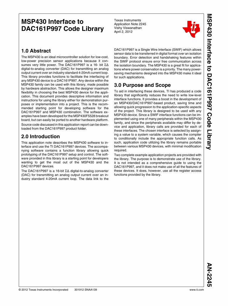
MSP430 Interface to DAC161P997 Code Library Texas Instruments Application Note 2245 Vishy Viswanathan April 2, 2012 1.0 Abstract The MSP430 is an ideal microcontroller solution for low-cost, low-power precision sensor applications because it con- sumes very little power. The DAC161P997 is a 16- bit ΣΔ digital-to-analog converter (DAC) for transmitting an analog output current over an industry standard 4-20mA current loop. This library provides functions to facilitate the interfacing of any MSP430 device to a DAC161P997. Any device within the MSP430 family can be used with this library, made possible by hardware abstraction. This allows the designer maximum flexibility in choosing the best MSP430 device for the appli- cation. This document provides descriptive information and instructions for using the library either for demonstration pur- poses or implementation into a project. This is the recom- mended starting point for developing software for the DAC161P997 and MSP430 combination. The software ex- amples have been developed for the MSP430F5528 breakout board, but can easily be ported to another hardware platform. Source code discussed in this application report can be down- loaded from the DAC161P997 product folder. 2.0 Introduction This application note describes the MSP430 software to in- terface and use the TI DAC161P997 devices. The accompa- nying software contains a function library allowing quick prototyping of the DAC161P997 setup and control. The soft- ware provided in this library is a starting point for developers wanting to get the most out of the MSP430 and the DAC161P997 devices. The DAC161P997 is a 16-bit ΣΔ digital-to-analog converter (DAC) for transmitting an analog output current over an in- dustry standard 4-20mA current loop. The data link to the DAC161P997 is a Single Wire Interface (SWIF) which allows sensor data to be transferred in digital format over an isolation boundary. Error detection and handshaking features within the SWIF protocol ensure error free communication across the isolation boundary. The MSP430 is a great fit for applica- tions where power conservation is a priority. The many power- saving mechanisms designed into the MSP430 make it ideal for such applications. 3.0 Purpose and Scope To aid in interfacing these devices, TI has produced a code library that significantly reduces the need to write low-level interface functions. It provides a boost in the development of an MSP430/DAC161P997-based product, saving time and allowing quick progression to the application-specific aspects of the project. This library is designed to be used with any MSP430 device. Since a SWIF interface functions can be im- plemented using one of many peripherals within the MSP430 family, and since the peripherals available may differ by de- vice and application, library calls are provided for each of these interfaces. The chosen interface is selected by assign- ing a value to a system variable, which causes the compiler to conditionally include the appropriate function calls. As such, application code utilizing the library remains portable between various MSP430 devices, with minimal modification required. Two complete example application projects are provided with the library. The purpose is to demonstrate use of the library. It is not intended as a comprehensive guide to using the DAC161P997, and it does not make use of all the features of these devices. It does, however, use all the register access functions provided by the library. © 2012 Texas Instruments Incorporated 301912 SNAA139 www.ti.com MSP430 Interface to DAC161P997 Code Library AN-2245
Transcript of Application Note 2245 MSP430 Interface to...
MSP430 Interface toDAC161P997 Code Library
Texas InstrumentsApplication Note 2245Vishy ViswanathanApril 2, 2012
1.0 AbstractThe MSP430 is an ideal microcontroller solution for low-cost,low-power precision sensor applications because it con-sumes very little power. The DAC161P997 is a 16- bit ΣΔdigital-to-analog converter (DAC) for transmitting an analogoutput current over an industry standard 4-20mA current loop.This library provides functions to facilitate the interfacing ofany MSP430 device to a DAC161P997. Any device within theMSP430 family can be used with this library, made possibleby hardware abstraction. This allows the designer maximumflexibility in choosing the best MSP430 device for the appli-cation. This document provides descriptive information andinstructions for using the library either for demonstration pur-poses or implementation into a project. This is the recom-mended starting point for developing software for theDAC161P997 and MSP430 combination. The software ex-amples have been developed for the MSP430F5528 breakoutboard, but can easily be ported to another hardware platform.
Source code discussed in this application report can be down-loaded from the DAC161P997 product folder.
2.0 IntroductionThis application note describes the MSP430 software to in-terface and use the TI DAC161P997 devices. The accompa-nying software contains a function library allowing quickprototyping of the DAC161P997 setup and control. The soft-ware provided in this library is a starting point for developerswanting to get the most out of the MSP430 and theDAC161P997 devices.
The DAC161P997 is a 16-bit ΣΔ digital-to-analog converter(DAC) for transmitting an analog output current over an in-dustry standard 4-20mA current loop. The data link to the
DAC161P997 is a Single Wire Interface (SWIF) which allowssensor data to be transferred in digital format over an isolationboundary. Error detection and handshaking features withinthe SWIF protocol ensure error free communication acrossthe isolation boundary. The MSP430 is a great fit for applica-tions where power conservation is a priority. The many power-saving mechanisms designed into the MSP430 make it idealfor such applications.
3.0 Purpose and ScopeTo aid in interfacing these devices, TI has produced a codelibrary that significantly reduces the need to write low-levelinterface functions. It provides a boost in the development ofan MSP430/DAC161P997-based product, saving time andallowing quick progression to the application-specific aspectsof the project. This library is designed to be used with anyMSP430 device. Since a SWIF interface functions can be im-plemented using one of many peripherals within the MSP430family, and since the peripherals available may differ by de-vice and application, library calls are provided for each ofthese interfaces. The chosen interface is selected by assign-ing a value to a system variable, which causes the compilerto conditionally include the appropriate function calls. Assuch, application code utilizing the library remains portablebetween various MSP430 devices, with minimal modificationrequired.
Two complete example application projects are provided withthe library. The purpose is to demonstrate use of the library.It is not intended as a comprehensive guide to using theDAC161P997, and it does not make use of all the features ofthese devices. It does, however, use all the register accessfunctions provided by the library.
© 2012 Texas Instruments Incorporated 301912 SNAA139 www.ti.com
MS
P430 In
terfa
ce to
DA
C161P
997 C
od
e L
ibra
ryA
N-2
245

4.0 File Organization
The library has been implemented with modular hardware abstraction. There is a header file specific to each of the hardwarecomponents (DAC161P997, MSP430, and the board). The hardware definition header files are shown in Table 1. Table 2 showsthe library code files and its header, and Table 3 shows the demonstration applications that accompanies the library.
TABLE 1. Hardware Definition Files
Filename Description
TI_DAC161P997.h
Definitions specific to the DAC161P997 device, including register locations and
commonly-used masks for use with these registers. Symbol baud rate
BAUD_RATE is chosen here. Permitted symbol baud rate range is 300-19200
symbols per second (sps). Symbol baud rate depends on the CPU clock defined
by the macro definition CPU_CLOCK. This implementation uses 8MHz CPU
clock.
TI_MSP430.h
Definitions specific to the MSP430 device; primarily, the pins used in the SWIF
data link. Also, labels are defined for use with the system variable
TI_DAC161P997_SER_INTF. This label selects the MSP430 peripheral
(Timer_A0, Timer_B0, and GPIO bit bang) used to implement the
TI_DAC161P997_SWIFSendSymbol function.
TI_MSP430_hardware_board.h
Definitions specific to the board being used such as the LED GPIO pin. SWIF
connections are not defined here because they are defined within
TI_MSP430.h The system variable TI_DAC161P997_SER_INTF is defined in this
file.
TABLE 2. Library Code
Filename Description
TI_MSP430_swif.c Functions for accessing the DAC161P997 registers via SWIF from MSP430 family
TI_MSP430_swif.h Function declarations for TI_MSP430_swif.c
www.ti.com 2
AN
-2245
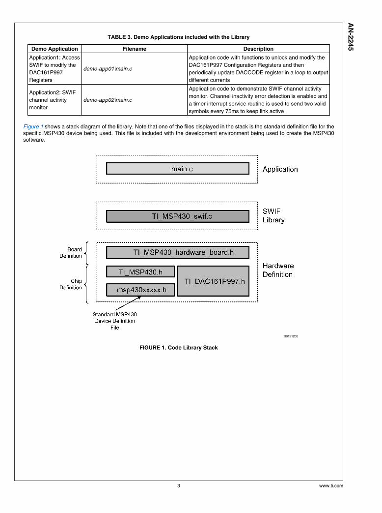
TABLE 3. Demo Applications included with the Library
Demo Application Filename Description
Application1: Access
SWIF to modify the
DAC161P997
Registers
demo-app01\main.c
Application code with functions to unlock and modify the
DAC161P997 Configuration Registers and then
periodically update DACCODE register in a loop to output
different currents
Application2: SWIF
channel activity
monitor
demo-app02\main.c
Application code to demonstrate SWIF channel activity
monitor. Channel inactivity error detection is enabled and
a timer interrupt service routine is used to send two valid
symbols every 75ms to keep link active
Figure 1 shows a stack diagram of the library. Note that one of the files displayed in the stack is the standard definition file for thespecific MSP430 device being used. This file is included with the development environment being used to create the MSP430software.
30191202
FIGURE 1. Code Library Stack
3 www.ti.com
AN
-2245
5.0 Functions
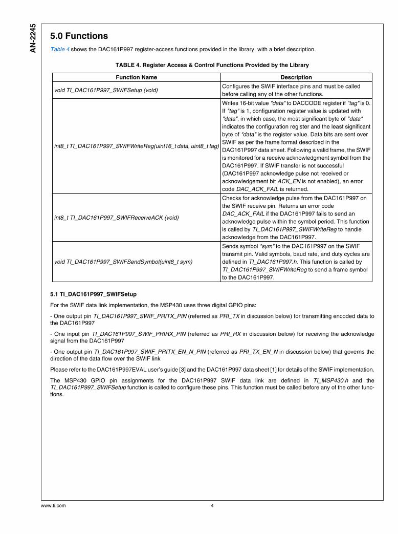
Table 4 shows the DAC161P997 register-access functions provided in the library, with a brief description.
TABLE 4. Register Access & Control Functions Provided by the Library
Function Name Description
void TI_DAC161P997_SWIFSetup (void)Configures the SWIF interface pins and must be called
before calling any of the other functions.
int8_t TI_DAC161P997_SWIFWriteReg(uint16_t data, uint8_t tag)
Writes 16-bit value "data" to DACCODE register if "tag" is 0.
If "tag" is 1, configuration register value is updated with
"data", in which case, the most significant byte of "data"
indicates the configuration register and the least significant
byte of "data" is the register value. Data bits are sent over
SWIF as per the frame format described in the
DAC161P997 data sheet. Following a valid frame, the SWIF
is monitored for a receive acknowledgment symbol from the
DAC161P997. If SWIF transfer is not successful
(DAC161P997 acknowledge pulse not received or
acknowledgement bit ACK_EN is not enabled), an error
code DAC_ACK_FAIL is returned.
int8_t TI_DAC161P997_SWIFReceiveACK (void)
Checks for acknowledge pulse from the DAC161P997 on
the SWIF receive pin. Returns an error code
DAC_ACK_FAIL if the DAC161P997 fails to send an
acknowledge pulse within the symbol period. This function
is called by TI_DAC161P997_SWIFWriteReg to handle
acknowledge from the DAC161P997.
void TI_DAC161P997_SWIFSendSymbol(uint8_t sym)
Sends symbol "sym" to the DAC161P997 on the SWIF
transmit pin. Valid symbols, baud rate, and duty cycles are
defined in TI_DAC161P997.h. This function is called by
TI_DAC161P997_SWIFWriteReg to send a frame symbol
to the DAC161P997.
5.1 TI_DAC161P997_SWIFSetup
For the SWIF data link implementation, the MSP430 uses three digital GPIO pins:
- One output pin TI_DAC161P997_SWIF_PRITX_PIN (referred as PRI_TX in discussion below) for transmitting encoded data tothe DAC161P997
- One input pin TI_DAC161P997_SWIF_PRIRX_PIN (referred as PRI_RX in discussion below) for receiving the acknowledgesignal from the DAC161P997
- One output pin TI_DAC161P997_SWIF_PRITX_EN_N_PIN (referred as PRI_TX_EN_N in discussion below) that governs thedirection of the data flow over the SWIF link
Please refer to the DAC161P997EVAL user’s guide [3] and the DAC161P997 data sheet [1] for details of the SWIF implementation.
The MSP430 GPIO pin assignments for the DAC161P997 SWIF data link are defined in TI_MSP430.h and theTI_DAC161P997_SWIFSetup function is called to configure these pins. This function must be called before any of the other func-tions.
www.ti.com 4
AN
-2245
5.2 TI_DAC161P997_SWIFWriteReg
The TI_DAC161P997_SWIFWriteReg function accepts the 16-bit payload and tag bit as inputs and automatically generates thedata frame with parity bits for transfer over the SWIF. Please refer to the DAC161P997 data sheet for details of the SWIF dataframe. The TI_DAC161P997_SWIFWriteReg function writes a byte of data into the specified configuration register address if"tag" sent is 1. Alternatively, it can write a 16-bit value to the DACCODE register if "tag" sent is 0. It calls the functionTI_DAC161P997_SWIFSendSymbol to send frame symbols over the SWIF PRI_TX pin using duty cycle encoded waveform. TheTI_DAC161P997_SWIFReceiveACK function is called at the end to handle the acknowledge symbol from the DAC161P997. IfSWIF transfer is not successful (DAC161P997 acknowledge pulse not received or acknowledgement bit ACK_EN is not enabled),an error code DAC_ACK_FAIL is returned.
5.3 TI_DAC161P997_SWIFSendSymbol
This function is used to send data symbols of the frame over SWIF PRI_TX pin as duty cycle encoded waveform. The individualsymbol period is defined through the BAUD_RATE and CPU_CLOCK macro definitions in TI_DAC161P997.h. The baud rate validrange is 300 to 19200 symbols per second. A version of the TI_DAC161P997_SWIFSendSymbol function is provided for thefollowing MSP430 peripherals:
• Timer_A0
• Timer_B0
• GPIO BitBang (default)
The system variable TI_DAC161P997_SER_INTF selects the peripheral to be used for implementing the TI_DAC161P997_SWIF-SendSymbol library function.
5 www.ti.com
AN
-2245
6.0 Using the Software
6.1 Prerequisites
To successfully compile, download and run the software described in this document, the following materials are needed:
• MSP430 Target Board MSP-TS430RGC64USB Board
• DAC161P997 Evaluation Board DAC161P997EVAL
• MSP430 USB Debugging Interface MSP430-FET430UIF
• IAR Embedded Workbench or TI Code Composer Studio for MSP430
The software can be adapted to run on other MSP430 hardware boards as well. See Section 5.3 for instructions.
A free, code size limited, but fully functional edition of IAR Embedded Workbench (IAR Kickstart) is available from the IAR Systemswebsite (www.iar.com) or from the TI MSP430 software tools page:
http://www.ti.com/lsds/ti/microcontroller/16-bit_msp430/msp430_software_landing.page.
As an alternative to IAR Embedded Workbench, it would be possible to use Code Composer. A trial edition of the Code Composeris available from the TI MSP430 software tools page.
6.2 Getting started
Follow these simple steps to get your application up and running:
1. Install IAR Workbench
2. Download the source code for this application note and unzip the files to your working directory
3. Open IAR Embedded Workbench and create a new project:
a. Select Project -> Create new project
b. Select tool chain MSP430
c. Base the project on the empty project template
d. Save (you will also be asked to save the current workspace).
4. Add the following C files from the software that you downloaded and unzipped in step 2:
• All C files from the code\library folder
• All C files from the code\demo-application-examples\demo-app01 folder
5. Open the "options..." dialog for the new project by right clicking the project name in the workspace window. A window shouldappear.
a. Under "General options", select the MSP device. For the MSP-TS430RGC64USB target board, use MSP430F5528.
b. Under "C/C++ compiler", click on the preprocessor pane.
i. The "Ignore standard include directories" tick box should not be ticked.
ii. In the "Additional include directories", add include paths telling the compiler where to find the header files included by theC files. You should add the $PROJ_DIR$\code\include folder.
c. Under "Debugger", select "FET Debugger" from the "Driver" drop down list.
d. Under "FET Debugger", in the "Connection" section, choose the connection type of the FET tool (e.g. Texas Instruments USB-IF). Leave the rest of the settings as is.
6. Click “OK” to close the options window.
7. Select “Project -> Rebuild All”. There should be no errors or warnings when IAR rebuilds the executables (if not done already,you will also be asked to save the current workspace).
8. The configuration of the hardware definition files in the library as distributed by TI is for an MSP430F5528 equipped board. Thesystem variable TI_DAC161P997_SER_INTF defined within TI_hardware_board.h identifies BITBANG as the method to imple-ment the DAC161P997 SWIF functions. TI_MSP430.h identifies the pins used for SWIF pins implementation.
www.ti.com 6
AN
-2245
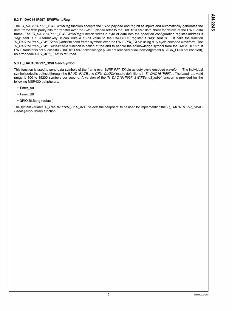
9. Connect the DAC161P997 Evaluation Board SWIF interface lines to the MSP430 target board pins as shown in Figure 2 below.
30191203
FIGURE 2. DAC161P997 to MSP430 Connection Diagram
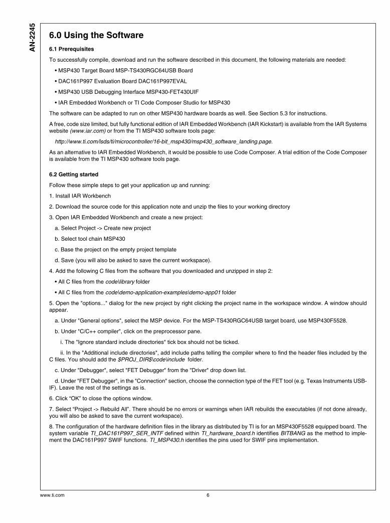
10. The DAC161P997 Evaluation Board jumper connections can be seen in Figure 3 and Table 5. The 4-20mA loop setup con-nections should be made between terminals 5 and 6 of J1 connector as described in the DAC161P997 user guide.
30191204
FIGURE 3. DAC161P997SDEVAL Jumper Settings
7 www.ti.com
AN
-2245
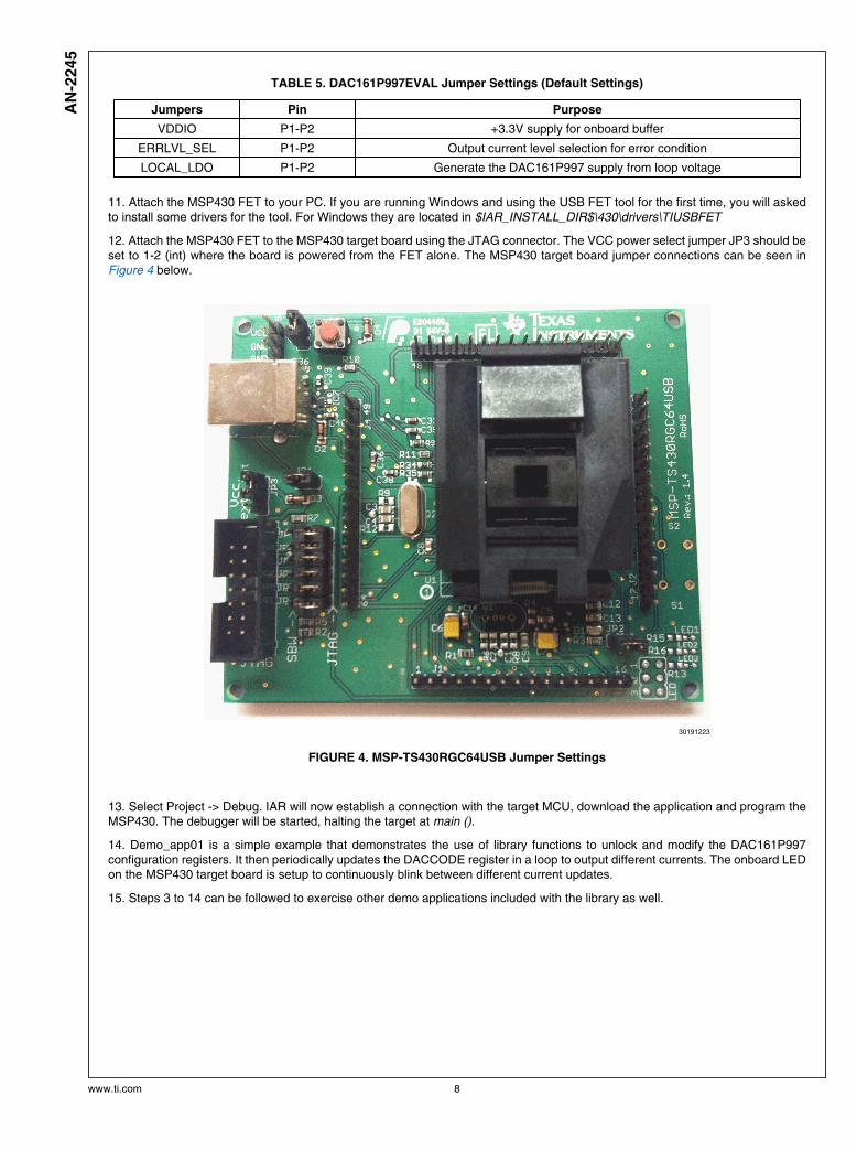
TABLE 5. DAC161P997EVAL Jumper Settings (Default Settings)
Jumpers Pin Purpose
VDDIO P1-P2 +3.3V supply for onboard buffer
ERRLVL_SEL P1-P2 Output current level selection for error condition
LOCAL_LDO P1-P2 Generate the DAC161P997 supply from loop voltage
11. Attach the MSP430 FET to your PC. If you are running Windows and using the USB FET tool for the first time, you will askedto install some drivers for the tool. For Windows they are located in $IAR_INSTALL_DIR$\430\drivers\TIUSBFET
12. Attach the MSP430 FET to the MSP430 target board using the JTAG connector. The VCC power select jumper JP3 should beset to 1-2 (int) where the board is powered from the FET alone. The MSP430 target board jumper connections can be seen inFigure 4 below.
30191223
FIGURE 4. MSP-TS430RGC64USB Jumper Settings
13. Select Project -> Debug. IAR will now establish a connection with the target MCU, download the application and program theMSP430. The debugger will be started, halting the target at main ().
14. Demo_app01 is a simple example that demonstrates the use of library functions to unlock and modify the DAC161P997configuration registers. It then periodically updates the DACCODE register in a loop to output different currents. The onboard LEDon the MSP430 target board is setup to continuously blink between different current updates.
15. Steps 3 to 14 can be followed to exercise other demo applications included with the library as well.
www.ti.com 8
AN
-2245
6.3 Adapting the Demo Project to Other Hardware
The procedure for adapting this code to other hardware is as follows:
• Edit the pin assignments within TI_MSP430.h for the DAC161P997 SWIF interface pins. The labels being referenced in the#define assignments will be drawn from the standard definition file (msp430.h) listed at the top of TI_MSP430.h.
• Edit the pin assignments in TI_MSP430_hardware_board.h, taking into account all the necessary connections on the boardbeing used. The assigned labels are drawn from the standard definition file (msp430.h) listed at the top of TI_MSP430.h.
• Assign the proper values to TI_DAC161P997_SER_INTF in TI_MSP430_hardware_board.h. The labels available for assign-ment can be found at the bottom of TI_MSP430.h.
• Set up appropriately the function (usc_init()) to configure the system clock source and clock rate. This will depend on yourhardware and the particular MSP430 MCU in use. Based on this, setup valid BAUD_RATE and CPU_CLK macro definitions inTI_DAC161P997.h.
• Make sure the physical hardware connections between the MSP430 target board and the DAC161P997EVAL are modifiedaccording to the pin assignments above.
After making these changes, rebuild the project and download the code image. The application should function as described earlier.
6.4 Using the Library with an Application
The same procedure as described in the section above should be applied in order to adapt the library to the new hardware.
The function TI_DAC161P997_SWIFSetup() should always be called after a POR event within the MSP430. After this the accessof registers is straightforward.
7.0 References
1. DAC161P997: Single-Wire 16-bit DAC for 4-20mA Loops, Data Sheet SNAS515
2. DAC161P997 Evaluation Development Platform Software
3. DAC161P997 Evaluation Board User’s Guide SNAU073
4. MSP430F551x/MSP430F552x Mixed Signal Microcontroller Data Sheet SLAS590
5. MSP430x5xx/MSP430x6xx Family User’s Guide SLAU208
6. MSP430F55xx 64-Pin Target Board MSP-TS430RGC64USB
7. MSP430 USB Debugging Interface MSP-FET430UIF
9 www.ti.com
AN
-2245
NotesA
N-2
245
MS
P430 In
terf
ace t
o D
AC
161P
997 C
od
e L
ibra
ry
www.ti.com