Application Monitoring Using NetFlow Deployment … that specify a value for a variable appear as...
33
Transcript of Application Monitoring Using NetFlow Deployment … that specify a value for a variable appear as...
Application Monitoring Using NetFlow Deployment Guide
February 2012 Series

PrefaceFebruary 2012 Series
Preface
Who Should Read This GuideThis Cisco® Smart Business Architecture (SBA) guide is for people who fill a variety of roles:
• Systems engineers who need standard procedures for implementing solutions
• Project managers who create statements of work for Cisco SBA implementations
• Sales partners who sell new technology or who create implementation documentation
• Trainers who need material for classroom instruction or on-the-job training
In general, you can also use Cisco SBA guides to improve consistency among engineers and deployments, as well as to improve scoping and costing of deployment jobs.
Release SeriesCisco strives to update and enhance SBA guides on a regular basis. As we develop a new series of SBA guides, we test them together, as a complete system. To ensure the mutual compatibility of designs in Cisco SBA guides, you should use guides that belong to the same series.
All Cisco SBA guides include the series name on the cover and at the bottom left of each page. We name the series for the month and year that we release them, as follows:
month year Series
For example, the series of guides that we released in August 2011 are the “August 2011 Series”.
You can find the most recent series of SBA guides at the following sites:
Customer access: http://www.cisco.com/go/sba
Partner access: http://www.cisco.com/go/sbachannel
How to Read CommandsMany Cisco SBA guides provide specific details about how to configure Cisco network devices that run Cisco IOS, Cisco NX-OS, or other operating systems that you configure at a command-line interface (CLI). This section describes the conventions used to specify commands that you must enter.
Commands to enter at a CLI appear as follows:
configure terminal
Commands that specify a value for a variable appear as follows:
ntp server 10.10.48.17
Commands with variables that you must define appear as follows:
class-map [highest class name]
Commands shown in an interactive example, such as a script or when the command prompt is included, appear as follows:
Router# enable
Long commands that line wrap are underlined. Enter them as one command:
wrr-queue random-detect max-threshold 1 100 100 100 100 100 100 100 100
Noteworthy parts of system output or device configuration files appear highlighted, as follows:
interface Vlan64 ip address 10.5.204.5 255.255.255.0
Comments and QuestionsIf you would like to comment on a guide or ask questions, please use the forum at the bottom of one of the following sites:
Customer access: http://www.cisco.com/go/sba
Partner access: http://www.cisco.com/go/sbachannel
An RSS feed is available if you would like to be notified when new comments are posted.
Table of ContentsFebruary 2012 Series
What’s In This SBA Guide . . . . . . . . . . . . . . . . . . . . . . . . . . . . . . . . . . . . . . . . . . . . . . . . . .1
About SBA . . . . . . . . . . . . . . . . . . . . . . . . . . . . . . . . . . . . . . . . . . . . . . . . . . . . . . . . . . . . . . 1
About This Guide . . . . . . . . . . . . . . . . . . . . . . . . . . . . . . . . . . . . . . . . . . . . . . . . . . . . . . . 1
Introduction . . . . . . . . . . . . . . . . . . . . . . . . . . . . . . . . . . . . . . . . . . . . . . . . . . . . . . . . . . . . . . . .2
Business Overview . . . . . . . . . . . . . . . . . . . . . . . . . . . . . . . . . . . . . . . . . . . . . . . . . . . . . . 2
Technology Overview . . . . . . . . . . . . . . . . . . . . . . . . . . . . . . . . . . . . . . . . . . . . . . . . . . . 2
Deployment Details . . . . . . . . . . . . . . . . . . . . . . . . . . . . . . . . . . . . . . . . . . . . . . . . . . . . . . . .9
Configuring a Device to Export NetFlow Information . . . . . . . . . . . . . . . . . . . 11
Monitoring NetFlow Data . . . . . . . . . . . . . . . . . . . . . . . . . . . . . . . . . . . . . . . . . . . . . . . 15
Appendix A: Product List . . . . . . . . . . . . . . . . . . . . . . . . . . . . . . . . . . . . . . . . . . . . . . . . .21
Appendix B: Full show flow monitor Output . . . . . . . . . . . . . . . . . . . . . . . . . . . . . . 22
Appendix C: NetFlow-Enabled Device Configuration . . . . . . . . . . . . . . . . . . . . 23
Table of Contents
ALL DESIGNS, SPECIFICATIONS, STATEMENTS, INFORMATION, AND RECOMMENDATIONS (COLLECTIVELY, “DESIGNS”) IN THIS MANUAL ARE PRESENTED “AS IS,” WITH ALL FAULTS. CISCO AND ITS SUPPLIERS DISCLAIM ALL WARRANTIES, INCLUDING, WITHOUT LIMITATION, THE WARRANTY OF MERCHANTABILITY, FITNESS FOR A PARTICULAR PURPOSE AND NONINFRINGEMENT OR ARISING FROM A COURSE OF DEALING, USAGE, OR TRADE PRACTICE. IN NO EVENT SHALL CISCO OR ITS SUPPLIERS BE LIABLE FOR ANY INDIRECT, SPECIAL, CONSEQUENTIAL, OR INCIDENTAL DAMAGES, INCLUDING, WITHOUT LIMITA- TION, LOST PROFITS OR LOSS OR DAMAGE TO DATA ARISING OUT OF THE USE OR INABILITY TO USE THE DESIGNS, EVEN IF CISCO OR ITS SUPPLIERS HAVE BEEN ADVISED OF THE POSSIBILITY OF SUCH DAMAGES. THE DESIGNS ARE SUBJECT TO CHANGE WITHOUT NOTICE. USERS ARE SOLELY RESPONSIBLE FOR THEIR APPLICATION OF THE DESIGNS. THE DESIGNS DO NOT CONSTITUTE THE TECHNICAL OR OTHER PROFESSIONAL ADVICE OF CISCO, ITS SUPPLIERS OR PARTNERS. USERS SHOULD CONSULT THEIR OWN TECHNICAL ADVISORS BEFORE IMPLEMENTING THE DESIGNS. RESULTS MAY VARY DEPENDING ON FACTORS NOT TESTED BY CISCO.
Any Internet Protocol (IP) addresses used in this document are not intended to be actual addresses. Any examples, command display output, and figures included in the document are shown for illustrative purposes only. Any use of actual IP addresses in illustrative content is unintentional and coincidental.
© 2012 Cisco Systems, Inc. All rights reserved.

What’s In This SBA Guide
About SBACisco SBA helps you design and quickly deploy a full-service business network. A Cisco SBA deployment is prescriptive, out-of-the-box, scalable, and flexible.
Cisco SBA incorporates LAN, WAN, wireless, security, data center, application optimization, and unified communication technologies—tested together as a complete system. This component-level approach simplifies system integration of multiple technologies, allowing you to select solutions that solve your organization’s problems—without worrying about the technical complexity.
For more information, see the How to Get Started with Cisco SBA document:
http://www.cisco.com/en/US/docs/solutions/Enterprise/Borderless_Networks/Smart_Business_Architecture/SBA_Getting_Started.pdf
About This GuideThis additional deployment guide includes the following sections:
• BusinessOverview—The challenge that your organization faces. Business decision makers can use this section to understand the relevance of the solution to their organizations’ operations.
• TechnologyOverview—How Cisco solves the challenge. Technical decision makers can use this section to understand how the solution works.
• DeploymentDetails—Step-by-step instructions for implementing the solution. Systems engineers can use this section to get the solution up and running quickly and reliably.
This guide presumes that you have read the prerequisites guides, as shown on the Route to Success below.
1What’s In This SBA GuideFebruary 2012 Series
Route to SuccessTo ensure your success when implementing the designs in this guide, you should read any guides that this guide depends upon—shown to the left of this guide on the route above. Any guides that depend upon this guide are shown to the right of this guide.
For customer access to all SBA guides: http://www.cisco.com/go/sba For partner access: http://www.cisco.com/go/sbachannel
FoundationDesign Overview
FoundationDeployment Guide
Application MonitoringUsing NetflowDeployment Guide
BN
You are HerePrerequisite Guides

2IntroductionFebruary 2012 Series
Introduction
Business OverviewWAN networks are critical infrastructure that enable and support business processes throughout all the functions of an organization. For the staff responsible for planning, operation, and maintenance of the network and network services it is indispensable to have visibility into the current health of the network from end to end. It is also essential to gather short and long term information in order to fully understand how the network is performing and what applications are active on the network. NetFlow data from a net-work is equivalent to the call detail records available from voice and video call control systems.
These items are of high interest to an organization:
• What applications are in use and their impact on the network
• The specifics of who, what, when, where, and how of the network traffic
• The efficiency and utilization of network resources
• The impact of changes to the network
• Network anomalies that might signal security events
Capacity planning is one of the most important issues faced by enterprise companies in managing their networks. More an art than a science until recently, network capacity planning is all about balancing the need to meet user performance expectations against the realities of capital budgeting.
WAN bandwidth is expensive. Many companies attempt to control costs by acquiring the minimum bandwidth necessary to handle traffic on a circuit. This strategy can lead to congestion and degraded application performance.
Visibility into the network enables resource alignment, ensuring that resources are used appropriately in support of organizational goals. It also helps IT staff verify that quality of service (QoS) is implemented properly, so that latency sensitive traffic, such as voice or video, receives priority. Visibility also plays a vital role in network security as continuous traffic monitoring makes it possible to detect denial-of-service (DoS) attacks, network-propagated worms, and other undesirable network events.
This guide focuses primarily on application visibility within the network.
Technology OverviewNetFlow is an embedded capability within Cisco IOS Software on routers and switches. It allows an organization to gather traffic flow information.
In general, the key usages of NetFlow data include:
• Network planning and capacity planning
• Real-time network monitoring
• Application and user profiling
• Security incident detection and classification
• Accounting and billing
• Network data warehousing, forensics, and data mining
• Troubleshooting
The benefits of NetFlow to an organization include the organization’s ability to:
• Analyze new applications and their network impact by identifying changes to a known baseline
• Reduce peak WAN traffic by using NetFlow statistics to measure WAN traffic changes associated with different application policies and under-stand who is utilizing the network and the network top talkers
• Diagnose slow network performance, bandwidth hogs, and bandwidth utilization in real-time with command line interface or reporting tools
• Detect unauthorized WAN traffic and avoid costly upgrades by identify-ing the applications causing congestion
• Detect and monitor security anomalies and other network disruptions and their associated sources
• Validate proper QoS implementation and confirm that appropriate bandwidth has been allocated to each class of service (CoS) and that no CoS is over or undersubscribed
3IntroductionFebruary 2012 Series
Traditional NetFlow
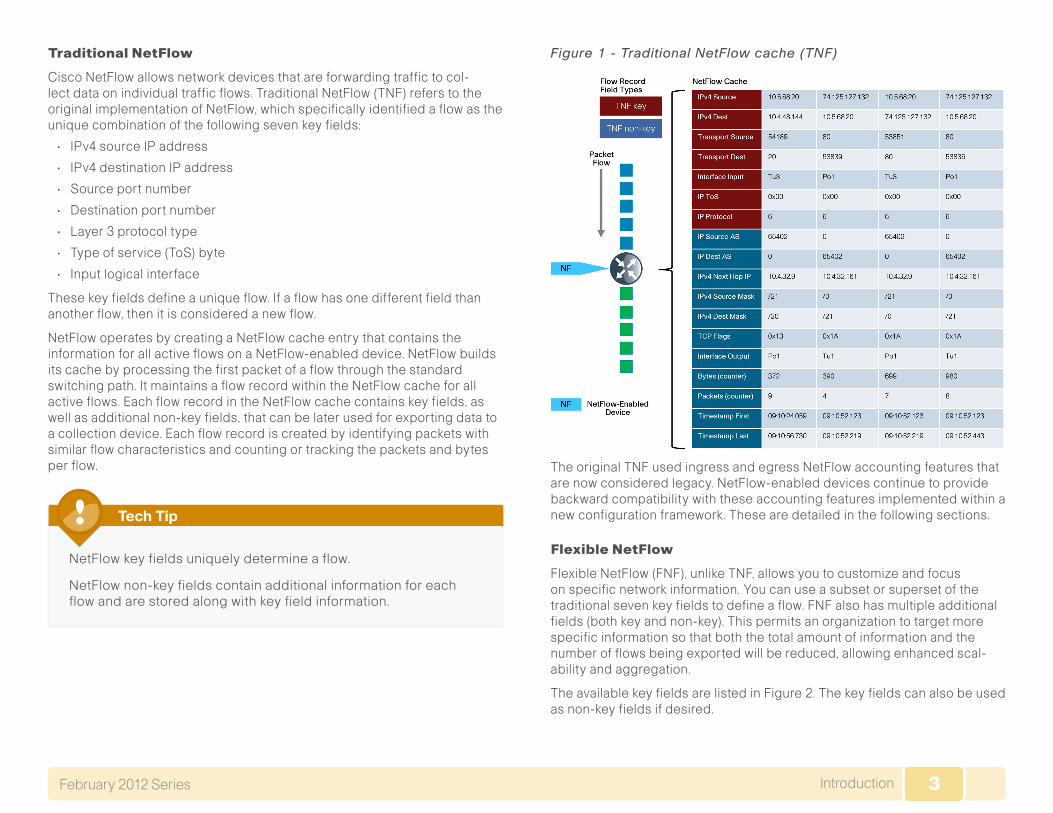
Cisco NetFlow allows network devices that are forwarding traffic to col-lect data on individual traffic flows. Traditional NetFlow (TNF) refers to the original implementation of NetFlow, which specifically identified a flow as the unique combination of the following seven key fields:
• IPv4 source IP address
• IPv4 destination IP address
• Source port number
• Destination port number
• Layer 3 protocol type
• Type of service (ToS) byte
• Input logical interface
These key fields define a unique flow. If a flow has one different field than another flow, then it is considered a new flow.
NetFlow operates by creating a NetFlow cache entry that contains the information for all active flows on a NetFlow-enabled device. NetFlow builds its cache by processing the first packet of a flow through the standard switching path. It maintains a flow record within the NetFlow cache for all active flows. Each flow record in the NetFlow cache contains key fields, as well as additional non-key fields, that can be later used for exporting data to a collection device. Each flow record is created by identifying packets with similar flow characteristics and counting or tracking the packets and bytes per flow.
NetFlow key fields uniquely determine a flow.
NetFlow non-key fields contain additional information for each flow and are stored along with key field information.
Tech Tip
Figure 1 - Traditional NetFlow cache (TNF)
The original TNF used ingress and egress NetFlow accounting features that are now considered legacy. NetFlow-enabled devices continue to provide backward compatibility with these accounting features implemented within a new configuration framework. These are detailed in the following sections.
Flexible NetFlow
Flexible NetFlow (FNF), unlike TNF, allows you to customize and focus on specific network information. You can use a subset or superset of the traditional seven key fields to define a flow. FNF also has multiple additional fields (both key and non-key). This permits an organization to target more specific information so that both the total amount of information and the number of flows being exported will be reduced, allowing enhanced scal-ability and aggregation.
The available key fields are listed in Figure 2. The key fields can also be used as non-key fields if desired.

4IntroductionFebruary 2012 Series
Figure 2 - FNF key fields The non-key fields that can be collected for each unique flow are shown in Figure 3.
Figure 3 - Non-key fields
Migration from TNF to FNF
The introduction of FNF support on the network devices requires a new method of configuration for the additional capabilities. You can also use this new configuration command line interface (CLI) to configure legacy TNF, making the original configuration CLI (now referred to as the “classic CLI”) unnecessary.
FNF includes several predefined records that you can use to start moni-toring traffic in your network. The predefined records ensure backward compatibility with NetFlow collector configurations that may not include FNF support. They have a unique combination of key and non-key fields that are backward compatible with legacy TNF configurations.
The predefined record netflowipv4originalinput used in our deployment is functionally equivalent to the original TNF ingress and egress NetFlow accounting features that predate the usage of flow records. A comparison between the classic and new configuration methods follows.
5IntroductionFebruary 2012 Series
TraditionalNetFlow-ClassicCLI
interface GigabitEthernet0/0 ip flow [ingress|egress]!ip flow-export destination 10.4.48.171 2055ip flow-export source Loopback0ip flow-export version 9ip flow-cache timeout active 1ip flow-cache timeout inactive 15
The new configuration CLI example uses the predefined recordipv4original-input, which includes the TNF key and non-key fields listed in Figure 1.
This example should be used to migrate legacy TNF deployments to the new CLI without changing device behavior.
TraditionalNetFlow-NewConfigurationCLI
interface GigabitEthernet0/0 ip flow monitor Monitor-NF [input|output]!flow exporter Export-NF-1 destination 10.4.48.171 source Loopback0 transport udp 2055 export-protocol netflow-v9 !flow monitor Monitor-NF record netflow ipv4 original-input exporter Export-NF-1 cache timeout active 1 cache timeout inactive 15
NBAR
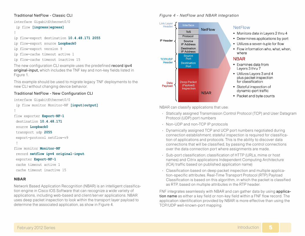
Network Based Application Recognition (NBAR) is an intelligent classifica-tion engine in Cisco IOS Software that can recognize a wide variety of applications, including web-based and client/server applications. NBAR uses deep packet inspection to look within the transport layer payload to determine the associated application, as show in Figure 4.
Figure 4 - NetFlow and NBAR integration
NBAR can classify applications that use:
• Statically assigned Transmission Control Protocol (TCP) and User Datagram Protocol (UDP) port numbers
• Non-UDP and non-TCP IP protocols
• Dynamically assigned TCP and UCP port numbers negotiated during connection establishment; stateful inspection is required for classifica-tion of applications and protocols. This is the ability to discover data connections that will be classified, by passing the control connections over the data connection port where assignments are made.
• Sub-port classification; classification of HTTP (URLs, mime or host names) and Citrix applications Independent Computing Architecture (ICA) traffic based on published application name)
• Classification based on deep packet inspection and multiple applica-tion-specific attributes. Real-Time Transport Protocol (RTP) Payload Classification is based on this algorithm, in which the packet is classified as RTP, based on multiple attributes in the RTP header.
FNF integrates seamlessly with NBAR and can gather data by using applica-tionname as either a key field or non-key field within a FNF flow record. The application identification provided by NBAR is more effective than using the TCP/UDP well-known-port mapping.

6IntroductionFebruary 2012 Series
Application identification with NBAR is one of the key reasons to make the migration from TNF to FNF.
Tech Tip
The Cisco SBA implementation of FNF selects additional fields that provide improved application visibility within the deployed architecture. These additional fields are listed in Figure 5.
Figure 5 - NetFlow Cache (FNF)
NetFlow Interaction with Application Optimization
The Cisco SBA midsize architecture includes application optimization using Cisco Wide Area Application Services (Cisco WAAS) to acceler-ate and optimize data over a WAN network. Full deployment details are available in the Smart Business Architecture—Borderless Networks for Midsize Organizations Foundation Deployment Guide in the Application Optimization Module.
You can configure NetFlow so that information can be gathered at multiple points along the path between a source and destination. When you use application optimization, the interface you select to monitor and the direc-tion being monitored affect the data cached by the network device. The topology in Figure 6 illustrates the potential complexity.
You can monitor traffic bound for a remote site across the WAN in two places. The flows cached inbound on the LAN-facing interface reflect uncompressed data before being optimized by the Cisco WAAS. The same flows when cached outbound on the WAN-facing interface reflect com-pressed data that has been optimized by the Cisco WAAS.
Figure 6 - Application optimization and NetFlow

7IntroductionFebruary 2012 Series
The Cisco SBA recommendation for NetFlow with application optimization is to configure inbound and outbound flow monitoring on both the LAN-facing and WAN-facing interfaces. This ensures that all of the flow information is captured. The flow data that is collected on the LAN-facing interfaces provides an accurate view of the applications in use and their true network usage. The flow data that is collected on the WAN-facing interfaces accu-rately reflects the amount of network traffic that is transmitted and received to and from the WAN.
It is necessary to filter data during analysis depending on whether a LAN-facing or WAN-facing analysis is required.
Tech Tip
Monitoring
The NetFlow data can be viewed directly from the NetFlow-enabled device through the use of CLI show commands, but this method is somewhat cumbersome and it is difficult to correlate the data across multiple devices.
The flow details are exported to an external device running a flow collec-tor service as shown in Figure 7. The cached flow data is sent periodically based upon configurable timers. The collector is capable of storing an extensive history of flow information that was switched within the NetFlow device. NetFlow is very efficient, the amount of export data being only a small percentage of the actual traffic in the router or switch. NetFlow accounts for every packet (when in non-sampled mode) and provides a highly condensed and detailed view of all network traffic that entered the router or switch. The NetFlow collector should be located in the server room or data center.
Figure 7 - NetFlow export to collector
The most effective to way to view NetFlow data is through a dedicated analy-sis application, which is typically paired with the flow collector service. The various applications are typically focused either on traffic analysis, security (anomaly detection and denial of service), or billing. TNF monitoring appli-cations expect a standard set of fields to be exported. Each specific FNF monitoring application will likely have a custom set of NetFlow attributes and a particular export format that must be configured on the NetFlow-enabled device before data can be sent to the collector.
8IntroductionFebruary 2012 Series
The requirements for implementing FNF are highly dependent on which col-lector/analysis application is going to be used. This guide provides example deployment guidance for both TNF and FNF in the “Deployment Details” section of this guide for the following applications:
• Traditional NetFlow only: SolarWinds Orion NetFlow Traffic Analyzer (NTA)
• Flexible NetFlow: Plixer Scrutinizer
This guide uses these applications for the following reasons:
• Significant usage within a typical Cisco SBA midsize organization
• Dedicated focus on NetFlow analysis
• Ease of use
• Industry leadership with FNF support (Plixer)
This guide focuses on configuring TNF and FNF within the network topology detailed in the Smart Business Architecture—Borderless Networks for Midsize Organizations Foundation Deployment Guide and enables NetFlow on all devices that support FNF with the tested hardware and software combinations. This includes the headquarters WAN router and the remote-site routers.
9Deployment DetailsFebruary 2012 Series
Deployment Details
Cisco routers and switches support two NetFlow configuration methods: a newer method, which is required for FNF deployments, and an older method, which is limited to TNF deployments only. This guide will focus on the newer method, which you can use to support both FNF and TNF deployment.
FNF and TNF are enabled on the WAN routers used in Cisco SBA midsize architecture. The specific data fields collected and the appropriate timer values used on the NetFlow-enabled devices are documented within the following procedures.

10Deployment DetailsFebruary 2012 Series
Figure 8 - Cisco SBA midsize architecture with NetFlow enabled
11Deployment DetailsFebruary 2012 Series
The following process must be completed to enable NetFlow data collection and optional data export.
• Create an FNF flow record or select a built-in flow record to use with TNF.
• Create a flow exporter for each external NetFlow collector.
• Create a flow monitor and associate it with either a custom or built-in flow record. You must also assign one or more flow exporters if you want the data to be analyzed on an external collector.
• Assign the flow monitor to interfaces on the network device.
The procedures that follow include best practice recommendations for which key fields and non-key fields need to be collected to allow for effec-tive application monitoring on your network. This guide includes two sets of examples within the procedures. These examples illustrate how to integrate with both NetFlow collectors that support TNF only, as well as NetFlow collectors that support FNF.
Configuring a Device to Export NetFlow Information
1. Create flexible NetFlow flow record
2. Create flow exporter
3. Create a flow monitor
4. Apply flow monitor to WAN and LAN
Process
Procedure 1 Create flexible NetFlow flow record
Flexible NetFlow requires the explicit configuration of a flow record that consists of both key fields and non-key fields. This procedure provides guid-ance on how to configure a user-defined flow record that includes all of the TNF fields (both key and non-key) as well as additional FNF fields (both key and non-key). The resulting flow record includes the full subset of TNF fields used in classic NetFlow deployments.
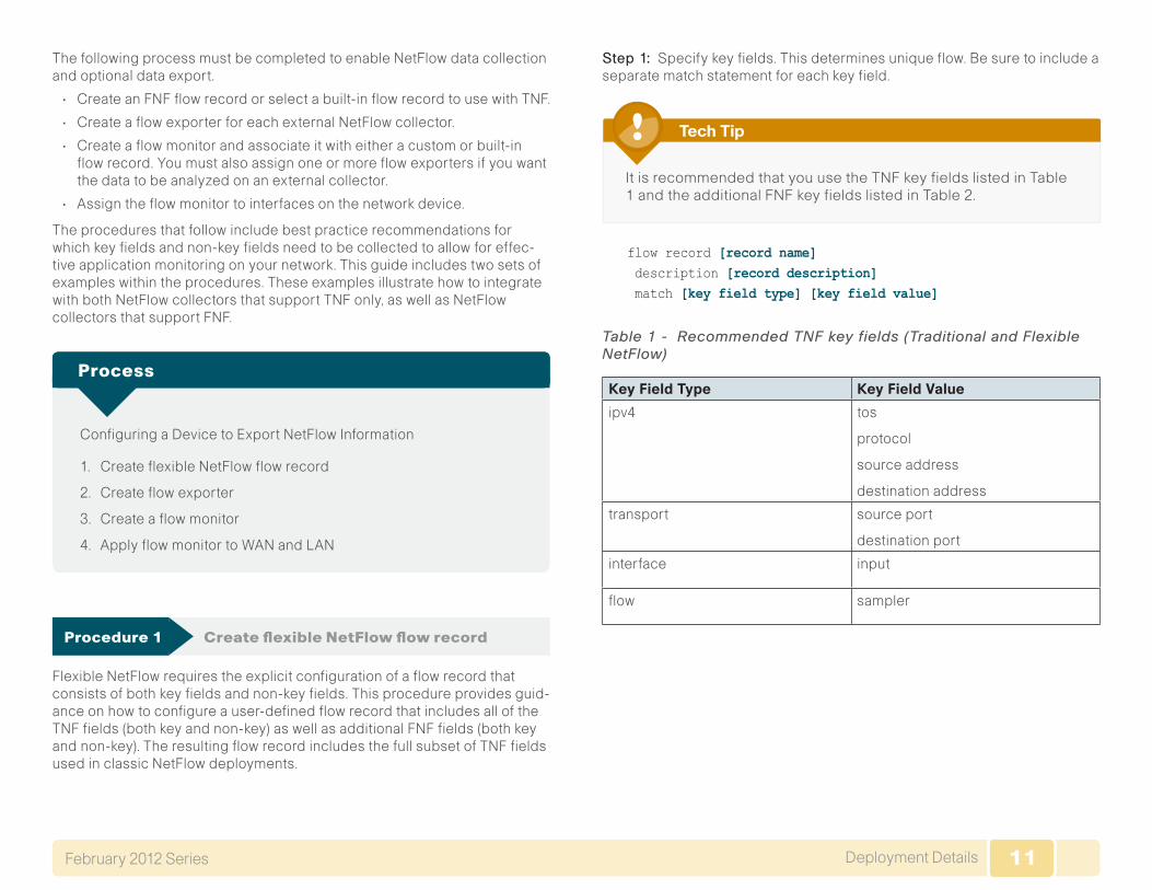
Step 1: Specify key fields. This determines unique flow. Be sure to include a separate match statement for each key field.
It is recommended that you use the TNF key fields listed in Table 1 and the additional FNF key fields listed in Table 2.
Tech Tip
flow record [record name] description [record description] match [key field type] [key field value]
Table 1 - Recommended TNF key fields (Traditional and Flexible NetFlow)
Key Field Type Key Field Value
ipv4 tos
protocol
source address
destination address
transport source port
destination port
interface input
flow sampler

12Deployment DetailsFebruary 2012 Series
Table 2 - Recommended additional FNF key fields (Flexible NetFlow only)
Key Field Type Key Field Value Comments
flow direction Allows for ingress/egress flow collection on same interface
application name Enables collection of NBAR information for each flow
Step 2: Specify non-key fields to be collected for each unique flow. Be sure to include a separate collect statement for each non-key field.
Flexible NetFlow allows for the use of additional user specified non-key fields. It is recommended that you use the additional TNF non-key fields listed in Table 3 and the additional FNF non-key fields listed in Table 4.
flow record [record name] collect [non-key field type] [non-key field value]
Table 3 - Recommended TNF non-key fields (traditional and flex-ible NetFlow)
Non-Key Field Type Non-Key Field Value
routing source as
destination as
next-hop address ipv4
ipv4 source mask
destination mask
transport tcp flags
Interface output
counter bytes
packets
timestamp sys-uptime first
sys-uptime last
Table 4 - Recommended additional FNF non-key (flexible NetFlow only)
Non-Key Field Type Key Field Value Comments
ipv4 dscp
id
source prefix
Additional IPv4 information for each flow
Example
flow record Record-FNF description Flexible NetFlow with NBAR Flow Record match ipv4 tos match ipv4 protocol match ipv4 source address match ipv4 destination address match transport source-port match transport destination-port match interface input match flow direction match application name collect routing source as collect routing destination as collect routing next-hop address ipv4 collect ipv4 dscp collect ipv4 id collect ipv4 source prefix collect ipv4 source mask collect ipv4 destination mask collect transport tcp flags collect interface output collect counter bytes collect counter packets collect timestamp sys-uptime first collect timestamp sys-uptime last

13Deployment DetailsFebruary 2012 Series
Procedure 2 Create flow exporter
Step 1: The NetFlow data that is stored in the cache of the network device can be more effectively analyzed when exported to an external collector.
Creating a flow exporter is only required when exporting data to an external collector. This procedure may be skipped if data is to be analyzed only on the network device.
Most external collectors use SNMP to retrieve the interface table from the network device. Please ensure that you have completed the relevant procedure “Enable SNMP for Management” from the Smart Business Architecture—Borderless Networks for Midsize Organizations Foundation Deployment Guide.
Reader Tip
Step 2: Different NetFlow collector applications support different export version formats (v5 and v9) and expect to receive the exported data on a particular UDP or TCP port. In this deployment the collector applications used for testing used the parameters designated in Table 5.
Table 5 - Tested NetFlow Collector Parameters
Vendor Application Version CapabilityExport Protocol
Destination Port
Plixer Scrutinizer 8.6.2 Flexible NetFlow
netflow-v9
UDP 2055
SolarWinds NetFlow Traffic Analyzer
3.8.0 Traditional NetFlow
netflow-v9
UDP 2055
Step 3: Configure a basic flow exporter.
flow exporter [exporter name] description [exporter description] destination [NetFlow collector IP address] source Loopback0 transport [UDP or TCP] [port number] export-protocol [export protocol]
Step 4: Configure additional parameters for FNF. Note that this step is only required when you are exporting FNF records in NetFlow v9 format.
flow exporter [exporter name] option interface-table option application-table
Example (Flexible NetFlow with Plixer)
flow exporter Export-FNF-Plixer description FNF v9 destination 10.10.48.171 source Loopback0 transport udp 2055 export-protocol netflow-v9 option interface-table option application-table
Example (Traditional NetFlow with SolarWinds)
flow exporter Export-TNF-Solarwinds description TNF v9 destination 10.10.48.170 source Loopback0 transport udp 2055 export-protocol netflow-v9
14Deployment DetailsFebruary 2012 Series
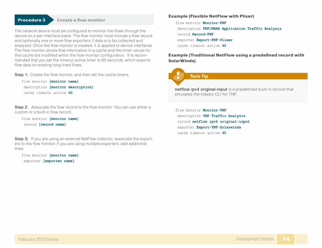
Procedure 3 Create a flow monitor
The network device must be configured to monitor the flows through the device on a per-interface basis. The flow monitor must include a flow record and optionally one or more flow exporters if data is to be collected and analyzed. Once the flow monitor is created, it is applied to device interfaces. The flow monitor stores flow information in a cache and the timer values for this cache are modified within the flow monitor configuration. It is recom-mended that you set the timeout active timer to 60 seconds, which exports flow data on existing long-lived flows.
Step 1: Create the flow monitor, and then set the cache timers.
flow monitor [monitor name] description [monitor description] cache timeout active 60
Step 2: Associate the flow record to the flow monitor. You can use either a custom or a built-in flow record.
flow monitor [monitor name] record [record name]
Step 3: If you are using an external NetFlow collector, associate the export-ers to the flow monitor. If you are using multiple exporters, add additional lines.
flow monitor [monitor name] exporter [exporter name]
Example (Flexible NetFlow with Plixer)
flow monitor Monitor-FNF description FNF/NBAR Application Traffic Analysis record Record-FNF exporter Export-FNF-Plixer cache timeout active 60
Example (Traditional NetFlow using a predefined record with SolarWinds)
netflowipv4original-input is a predefined built-in record that emulates the classic CLI for TNF.
Tech Tip
flow monitor Monitor-TNF description TNF Traffic Analysis record netflow ipv4 original-input exporter Export-TNF-Solarwinds cache timeout active 60

15Deployment DetailsFebruary 2012 Series
Procedure 4 Apply flow monitor to WAN and LAN
A best practice for NetFlow is to monitor all inbound and outbound traffic to the network device. This method covers all traffic regardless of encryption or application optimization.
Be sure to include apply the flow monitor to all device interfaces.
Tech Tip
Step 1: Apply the flow monitor to the device interface.
interface [name] ip flow monitor [monitor name] input ip flow monitor [monitor name] output
Example
interface GigabitEthernet0/0 description MPLS WAN Uplink ip flow monitor Monitor-FNF input ip flow monitor Monitor-FNF outputinterface GigabitEthernet0/2.64 description Wired Data ip flow monitor Monitor-FNF input ip flow monitor Monitor-FNF output
Monitoring NetFlow Data
1. View raw flow data unfiltered
2. Filter and view raw flow data
3. Sort and format flow data
4. Example reports from NetFlow collectors
Process
The data stored in the cache of the network device can be viewed in a number of different ways to address common use cases. These methods will be covered briefly to provide examples of how to access the flow data.
Procedure 1 View raw flow data unfiltered
The simplest method to view the NetFlow cache is via the following com-mand, which provides a summary of the cache status followed by a series of individual cache entries.
Step 1: Display the NetFlow cache.
show flow monitor [monitor name] cache
16Deployment DetailsFebruary 2012 Series
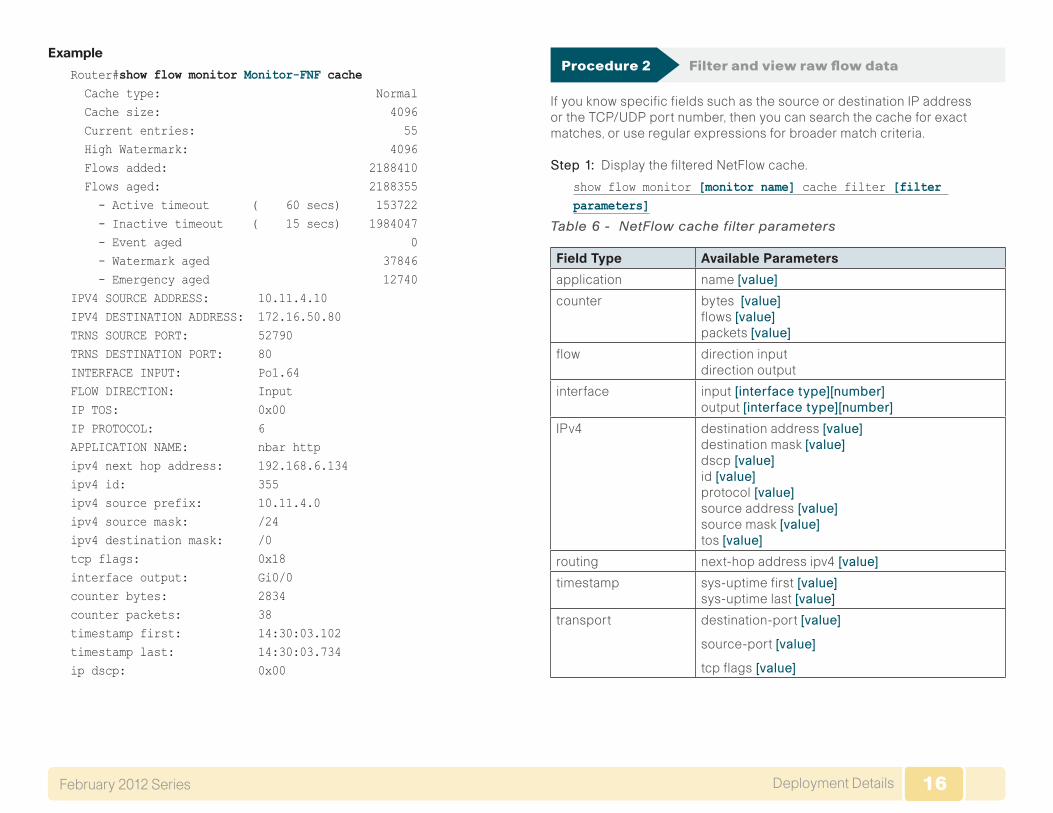
Example
Router#show flow monitor Monitor-FNF cache Cache type: Normal Cache size: 4096 Current entries: 55 High Watermark: 4096 Flows added: 2188410 Flows aged: 2188355 - Active timeout ( 60 secs) 153722 - Inactive timeout ( 15 secs) 1984047 - Event aged 0 - Watermark aged 37846 - Emergency aged 12740IPV4 SOURCE ADDRESS: 10.11.4.10 IPV4 DESTINATION ADDRESS: 172.16.50.80 TRNS SOURCE PORT: 52790 TRNS DESTINATION PORT: 80 INTERFACE INPUT: Po1.64 FLOW DIRECTION: Input IP TOS: 0x00 IP PROTOCOL: 6 APPLICATION NAME: nbar http ipv4 next hop address: 192.168.6.134 ipv4 id: 355 ipv4 source prefix: 10.11.4.0 ipv4 source mask: /24 ipv4 destination mask: /0 tcp flags: 0x18 interface output: Gi0/0 counter bytes: 2834 counter packets: 38 timestamp first: 14:30:03.102 timestamp last: 14:30:03.734 ip dscp: 0x00
Procedure 2 Filter and view raw flow data
If you know specific fields such as the source or destination IP address or the TCP/UDP port number, then you can search the cache for exact matches, or use regular expressions for broader match criteria.
Step 1: Display the filtered NetFlow cache.
show flow monitor [monitor name] cache filter [filter parameters]
Table 6 - NetFlow cache filter parameters
Field Type Available Parameters
application name [value]
counter bytes [value] flows [value] packets [value]
flow direction input direction output
interface input[interfacetype][number] output [interfacetype][number]
IPv4 destination address [value] destination mask [value] dscp[value] id [value] protocol[value] source address[value] source mask [value] tos [value]
routing next-hop address ipv4[value]
timestamp sys-uptime first[value] sys-uptime last [value]
transport destination-port [value]
source-port [value]
tcp flags[value]

17Deployment DetailsFebruary 2012 Series
Example
The following command shows how to verify that RTP streams have the proper QoS differentiated services code point (DSCP) settings.
Interactive video is configured to use DSCP cs4 and af41.
cs4 = 0x20 af41 = 0x22
Tech Tip
Router#show flow monitor Monitor-FNF cache filter application name regexp rtp
IPV4 SOURCE ADDRESS: 10.11.4.40 IPV4 DESTINATION ADDRESS: 10.10.48.27 TRNS SOURCE PORT: 2454 TRNS DESTINATION PORT: 51124 INTERFACE INPUT: Gi0/0 FLOW DIRECTION: Input IP TOS: 0x88 IP PROTOCOL: 17 APPLICATION NAME: nbar rtp ipv4 next hop address: 10.10.32.1 ipv4 id: 0 ipv4 source prefix: 10.11.0.0 ipv4 source mask: /16 ipv4 destination mask: /24 tcp flags: 0x00 interface output: Po32 counter bytes: 875384 counter packets: 2391 timestamp first: 15:32:52.027 timestamp last: 15:33:39.827 ip dscp: 0x22
Procedure 3 Sort and format flow data
The same fields that are available for searching the NetFlow cache are also available as simple sort fields. You can select any parameter from Table 7 and sort from either highest to lowest or lowest to highest. Additionally, you can format the command output in multiple ways as listed in Table 8, with the table output being most suitable for determining top traffic sources or destinations.
Table 7 - NetFlow cache sort parameters
Field Type Available Parameters
application name
counter bytes flows packets
flow direction input direction output
highest (default)
interface input[interfacetype][number] output [interfacetype][number]
IPv4 destination address [value] destination mask[value] dscp [value] id [value] protocol[value] source address[value] source mask[value] tos [value]
lowest
routing next-hop address ipv4[value]
timestamp sys-uptime first[value] sys-uptime last[value]
transport destination-port[value]
source-port[value]
tcp flags [value]

18Deployment DetailsFebruary 2012 Series
Table 8 - NetFlow cache output formats
Format Type Available Parameters
csv Suitable for cut/paste export
record (default) Best for viewing individual cache entries
table Suitable for on-screen display (requires 316 charac-ter width)
Example
The following command shows how to view the cache sorted by counterbytes and formatted as a table for on-screen viewing.
Router#show flow monitor Monitor-FNF cache sort counter bytes format table
Figure 9 shows partial output from the show flow monitor command. For an example of the full output, see Figure 14 in Appendix B.
Figure 9 - Example table output format
HQ-WAN-ISR3945#show flow monitor Monitor-FNF-Basic cache sort counter bytes form tableProcessed 57 flowsAggregated to 57 flowsShowing the top 20 flows
IPV4 SRC ADDR IPV4 DST ADDR TRNS SRC PORT TRNS DST PORT...=============== =============== ============= =============...10.10.48.27 10.11.4.40 51128 2456...10.11.4.40 10.10.48.27 2456 51128...10.10.48.27 10.11.4.40 51124 2454...10.11.4.40 10.10.48.27 2454 51124...10.11.4.40 10.10.48.27 2457 51129.... . . . . . . . . . . .
Procedure 4 Example reports from NetFlow collectors
This procedure highlights the types of reports that are available from Plixer Scrutinizer and SolarWinds NetFlow Traffic Analyzer (NTA).
One key advantage of using an external collector is the ability to aggregate the information collected across multiple network devices. A good collector provides the ability to both view data collected from a particular device and interface as well to correlate data collected across multiple devices and interfaces across the network.
Figure 10 - SolarWinds NTA endpoint summary

19Deployment DetailsFebruary 2012 Series
The NetFlow data cached locally on the network device is relatively short lived and is typically aged out by new flows within minutes. An external collector is essential to maintain a long term view of the traffic patterns on a network. The applications in use are most accurately determined by using FNF and NBAR.
Figure 11 - Plixer Scrutinizer - Applications NBAR report (72-hour timespan)
To fully illustrate the value of NBAR to identify application requires a com-parison because TNF can only identify applications through the use of either TCP or UDP Well Known Port (WKP). Since Plixer supports FNF and NBAR as well as TNF, you can generate the same report by using WKP.
Figure 12 - Plixer Scrutinizer Well Known Port report (72-hour timespan)
The primary difference is that many applications today, including video con-ferencing, tend to use a broad range of TCP or UDP ports that are dynami-cally chosen within a large known range. Various WKPs may fall within these ranges, and without additional application awareness provided by NBAR, the NetFlow collectors identify the applications incorrectly.
NetFlow is well suited for identifying, isolating and correcting network prob-lems, especially configuration problems that might manifest across multiple devices such as a misconfigured QoS policy. You can generate a report that filters down to an individual conversation between two endpoints that should be tagged bidirectionally with a specific DSCP value, such as an RTP video stream. If any intermediate devices along the path between the endpoints do not consistently show the data to be properly tagged, then there is likely to be a misconfigured device.
20Deployment DetailsFebruary 2012 Series
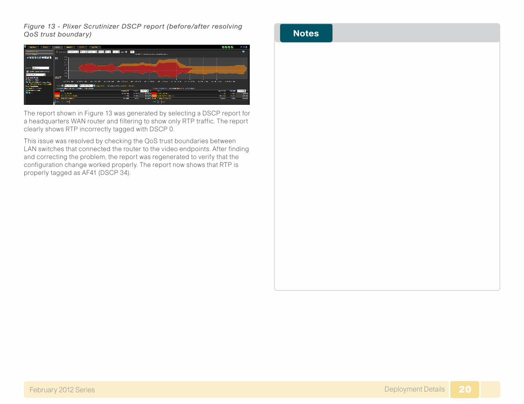
Figure 13 - Plixer Scrutinizer DSCP report (before/after resolving QoS trust boundary)
The report shown in Figure 13 was generated by selecting a DSCP report for a headquarters WAN router and filtering to show only RTP traffic. The report clearly shows RTP incorrectly tagged with DSCP 0.
This issue was resolved by checking the QoS trust boundaries between LAN switches that connected the router to the video endpoints. After finding and correcting the problem, the report was regenerated to verify that the configuration change worked properly. The report now shows that RTP is properly tagged as AF41 (DSCP 34).
21Appendix A: Product ListFebruary 2012 Series
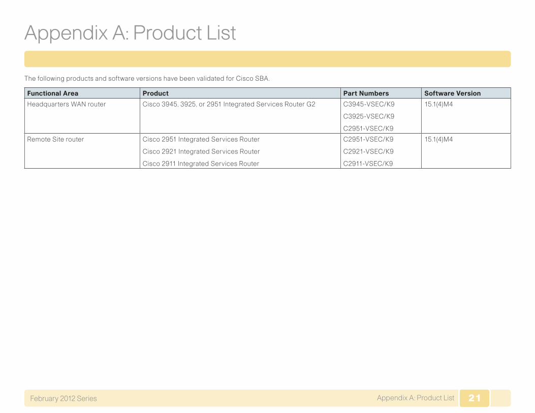
Appendix A: Product List
The following products and software versions have been validated for Cisco SBA.
Functional Area Product Part Numbers Software Version
Headquarters WAN router Cisco 3945, 3925, or 2951 Integrated Services Router G2 C3945-VSEC/K9
C3925-VSEC/K9
C2951-VSEC/K9
15.1(4)M4
Remote Site router Cisco 2951 Integrated Services Router
Cisco 2921 Integrated Services Router
Cisco 2911 Integrated Services Router
C2951-VSEC/K9
C2921-VSEC/K9
C2911-VSEC/K9
15.1(4)M4

22Appendix B: Full show flow monitor OutputFebruary 2012 Series
Appendix B: Full show flow monitor Output
The following figure is a full example of the output of the show flow monitor command.
Figure 14 - Example of full output from the show flow monitor commandHQ-WAN-ISR3945#show flow monitor Monitor-FNF-Basic cache sort counter bytes form tableProcessed 57 flowsAggregated to 57 flowsShowing the top 20 flows
IPV4 SRC ADDR IPV4 DST ADDR TRNS SRC PORT TRNS DST PORT INTF INPUT FLOW DIRN IP TOS IP PROT APP NAME ipv4 next hop addr ipv4 id ipv4 src prefix ipv4 src mask ipv4 dst mask tcp flags intf output bytes pkts time first time last ip dscp
=============== =============== ============= ============= ==================== ========= ====== ======= ================================ ================== ======= =============== ============= ============= ========= ==================== ========== ========== ============ ============ =======
10.10.48.27 10.11.4.40 51128 2456 Po32 Input 0x88 17 nbar rtp 192.168.6.130 0 10.10.48.0 /24 /16 0x00 Gi0/0 9295512 7407 11:50:25.751 11:51:20.119 0x22
10.11.4.40 10.10.48.27 2456 51128 Gi0/0 Input 0x88 17 nbar rtp 10.10.32.1 0 10.11.0.0 /16 /24 0x00 Po32 984272 816 11:51:14.731 11:51:20.103 0x22
10.10.48.27 10.11.4.40 51124 2454 Po32 Input 0x88 17 nbar rtp 192.168.6.130 0 10.10.48.0 /24 /16 0x00 Gi0/0 848448 2320 11:50:33.739 11:51:20.119 0x22
10.11.4.40 10.10.48.27 2454 51124 Gi0/0 Input 0x88 17 nbar rtp 10.10.32.1 0 10.11.0.0 /16 /24 0x00 Po32 336816 920 11:51:01.735 11:51:20.115 0x22
10.11.4.40 10.10.48.27 2457 51129 Gi0/0 Input 0x88 17 nbar rtcp 10.10.32.1 0 10.11.0.0 /16 /24 0x00 Po32 23280 193 11:51:01.811 11:51:20.111 0x22
10.10.48.27 10.11.4.40 51129 2457 Po32 Input 0x88 17 nbar rtcp 192.168.6.130 0 10.10.48.0 /24 /16 0x00 Gi0/0 8080 67 11:51:13.759 11:51:20.059 0x22
10.11.8.1 10.10.48.171 58822 2055 Gi0/0 Input 0x00 17 NBAR nfexport 10.10.32.1 40417 10.11.0.0 /16 /24 0x00 Po32 7934 18 11:50:42.791 11:51:19.791 0x00
10.10.32.10 10.10.32.126 2048 2048 Po32 Input 0x00 17 nbar unknown 0.0.0.0 24404 10.10.32.0 /25 /0 0x00 Null 5952 31 11:50:49.787 11:51:19.779 0x00
10.11.0.1 10.10.48.170 59003 2055 Gi0/0 Input 0x00 17 NBAR nfexport 10.10.32.1 29145 10.11.0.0 /16 /24 0x00 Po32 5416 22 11:50:22.995 11:51:16.003 0x00
10.11.4.40 10.10.48.27 2455 51125 Gi0/0 Input 0x88 17 nbar rtcp 10.10.32.1 0 10.11.0.0 /16 /24 0x00 Po32 1440 9 11:50:38.207 11:51:17.207 0x22
10.11.8.1 10.10.48.170 62188 2055 Gi0/0 Input 0x00 17 NBAR nfexport 10.10.32.1 28853 10.11.0.0 /16 /24 0x00 Po32 1424 8 11:50:56.671 11:51:19.671 0x00
10.10.48.27 10.11.4.40 51128 2456 Po32 Input 0x88 17 nbar unclassified 192.168.6.130 0 10.10.48.0 /24 /16 0x00 Gi0/0 1416 1 11:51:14.787 11:51:14.787 0x22
10.10.48.27 10.11.4.40 51125 2455 Po32 Input 0x88 17 nbar rtcp 192.168.6.130 0 10.10.48.0 /24 /16 0x00 Gi0/0 1120 7 11:50:51.859 11:51:18.859 0x22
10.11.5.12 10.10.48.20 51241 5060 Gi0/0 Input 0x60 6 nbar sip 10.10.32.1 28464 10.11.0.0 /16 /24 0x18 Po32 1029 3 11:51:10.103 11:51:10.107 0x18
10.11.13.51 10.10.48.20 52603 5060 Gi0/0 Input 0x60 6 nbar sip 10.10.32.1 2678 10.11.0.0 /16 /24 0x18 Po32 962 2 11:51:15.003 11:51:15.007 0x18
10.11.13.50 10.10.48.20 44932 5060 Gi0/0 Input 0x60 6 nbar sip 10.10.32.1 63844 10.11.0.0 /16 /24 0x18 Po32 919 3 11:51:05.323 11:51:05.331 0x18
10.10.48.147 10.10.32.254 54629 22 Po32 Input 0x00 6 port ssh 0.0.0.0 825 10.10.48.0 /24 /0 0x18 Null 800 9 11:51:16.431 11:51:20.115 0x00
10.11.12.41 10.10.48.27 58388 5061 Gi0/0 Input 0x00 6 NBAR 5061siptls 10.10.32.1 29257 10.11.0.0 /16 /24 0x18 Po32 765 2 11:51:15.987 11:51:15.999 0x00
10.10.48.20 10.11.13.50 5060 44932 Po32 Input 0x60 6 nbar sip 192.168.6.130 40962 10.10.48.0 /24 /16 0x18 Gi0/0 749 2 11:51:05.327 11:51:05.331 0x18
10.10.48.20 10.11.5.12 5060 51241 Po32 Input 0x60 6 nbar sip 192.168.6.130 28554 10.10.48.0 /24 /16 0x18 Gi0/0 746 2 11:51:10.103 11:51:10.103 0x18
23Appendix C: NetFlow-Enabled Device ConfigurationFebruary 2012 Series
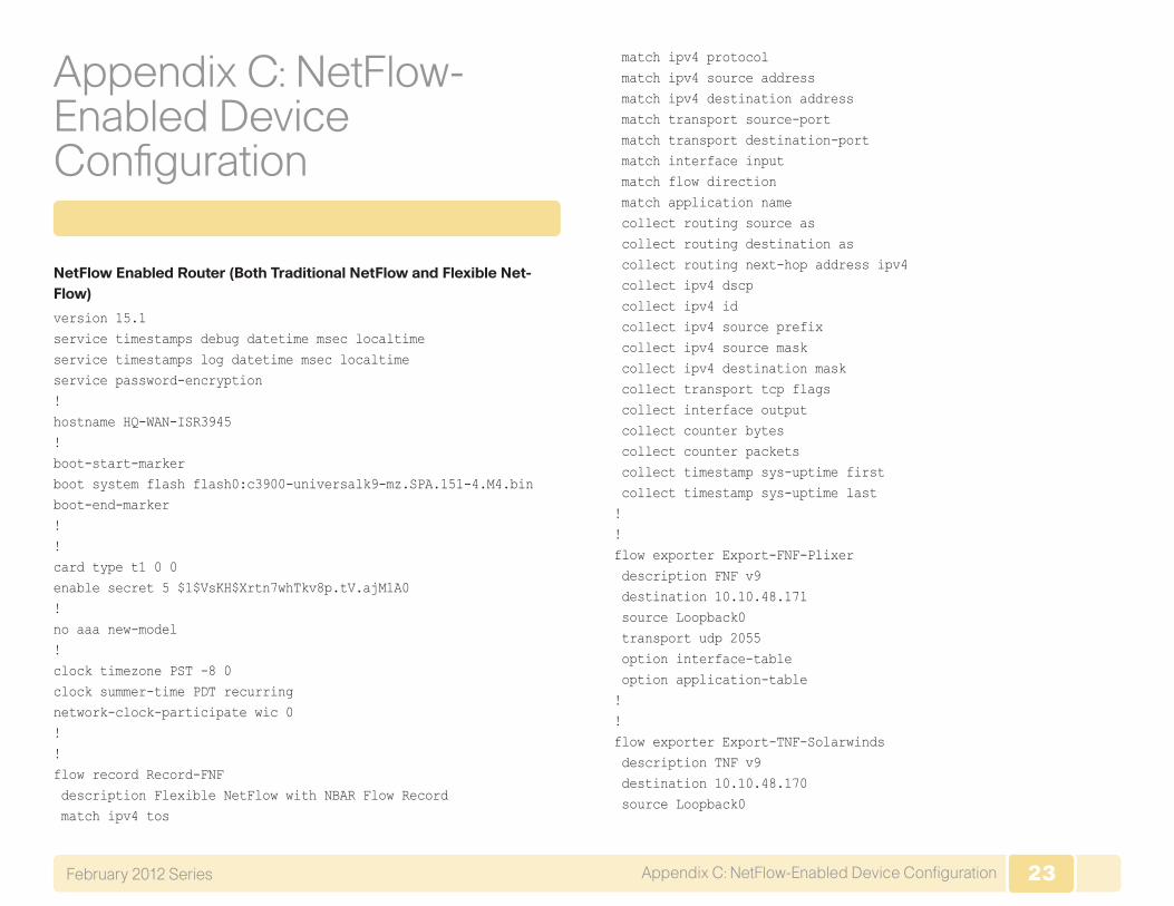
Appendix C: NetFlow-Enabled Device Configuration
NetFlow Enabled Router (Both Traditional NetFlow and Flexible Net-Flow)
version 15.1service timestamps debug datetime msec localtimeservice timestamps log datetime msec localtimeservice password-encryption!hostname HQ-WAN-ISR3945!boot-start-markerboot system flash flash0:c3900-universalk9-mz.SPA.151-4.M4.binboot-end-marker!!card type t1 0 0enable secret 5 $1$VsKH$Xrtn7whTkv8p.tV.ajM1A0!no aaa new-model!clock timezone PST -8 0clock summer-time PDT recurringnetwork-clock-participate wic 0 !!flow record Record-FNF description Flexible NetFlow with NBAR Flow Record match ipv4 tos
match ipv4 protocol match ipv4 source address match ipv4 destination address match transport source-port match transport destination-port match interface input match flow direction match application name collect routing source as collect routing destination as collect routing next-hop address ipv4 collect ipv4 dscp collect ipv4 id collect ipv4 source prefix collect ipv4 source mask collect ipv4 destination mask collect transport tcp flags collect interface output collect counter bytes collect counter packets collect timestamp sys-uptime first collect timestamp sys-uptime last!!flow exporter Export-FNF-Plixer description FNF v9 destination 10.10.48.171 source Loopback0 transport udp 2055 option interface-table option application-table!!flow exporter Export-TNF-Solarwinds description TNF v9 destination 10.10.48.170 source Loopback0
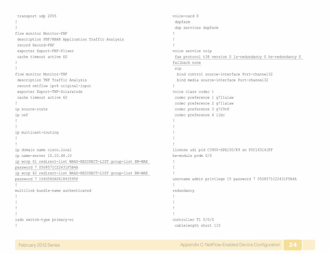
24Appendix C: NetFlow-Enabled Device ConfigurationFebruary 2012 Series
transport udp 2055!!flow monitor Monitor-FNF description FNF/NBAR Application Traffic Analysis record Record-FNF exporter Export-FNF-Plixer cache timeout active 60!!flow monitor Monitor-TNF description TNF Traffic Analysis record netflow ipv4 original-input exporter Export-TNF-Solarwinds cache timeout active 60!ip source-routeip cef!!ip multicast-routing !!ip domain name cisco.localip name-server 10.10.48.10ip wccp 61 redirect-list WAAS-REDIRECT-LIST group-list BN-WAE password 7 0508571C22431F5B4Aip wccp 62 redirect-list WAAS-REDIRECT-LIST group-list BN-WAE password 7 104D580A061843595F!multilink bundle-name authenticated!!!!isdn switch-type primary-ni!
voice-card 0 dspfarm dsp services dspfarm!!!voice service voip fax protocol t38 version 0 ls-redundancy 0 hs-redundancy 0 fallback none sip bind control source-interface Port-channel32 bind media source-interface Port-channel32!voice class codec 1 codec preference 1 g711ulaw codec preference 2 g711alaw codec preference 3 g729r8 codec preference 4 ilbc!!!!!license udi pid C3900-SPE150/K9 sn FOC14314JFFhw-module pvdm 0/0!!!username admin privilege 15 password 7 0508571C22431F5B4A!redundancy!!!!controller T1 0/0/0 cablelength short 110

25Appendix C: NetFlow-Enabled Device ConfigurationFebruary 2012 Series
pri-group timeslots 1-24 description PSTN PRI!controller T1 0/0/1 cablelength long 0db!ip ssh version 2!class-map match-any DATA match ip dscp af21 class-map match-any INTERACTIVE-VIDEO match dscp cs4 af41 class-map match-any CRITICAL-DATA match dscp cs3 af31 class-map match-any VOICE match dscp ef class-map match-any SCAVENGER match ip dscp cs1 af11 class-map match-any NETWORK-CRITICAL match ip dscp cs2 cs6 !!policy-map WAN class VOICE priority percent 10 class INTERACTIVE-VIDEO priority percent 23 class CRITICAL-DATA bandwidth percent 15 random-detect dscp-based class DATA bandwidth percent 19 random-detect dscp-based class SCAVENGER bandwidth percent 5 class NETWORK-CRITICAL bandwidth percent 3
class class-default bandwidth percent 25 random-detectpolicy-map WAN-QOS-POLICY class class-default shape average 10000000 service-policy WAN!!!interface Loopback0 ip address 10.10.32.254 255.255.255.255 ip pim sparse-mode!interface Port-channel32 ip address 10.10.32.126 255.255.255.128 ip wccp 61 redirect in ip pim sparse-mode ip flow monitor Monitor-FNF input ip flow monitor Monitor-TNF input ip flow monitor Monitor-FNF output ip flow monitor Monitor-TNF output hold-queue 150 in!interface Embedded-Service-Engine0/0 no ip address shutdown!interface GigabitEthernet0/0 description MPLS WAN uplink ip address 192.168.6.129 255.255.255.252 ip wccp 62 redirect in ip pim sparse-mode ip flow monitor Monitor-FNF input ip flow monitor Monitor-TNF input ip flow monitor Monitor-FNF output ip flow monitor Monitor-TNF output
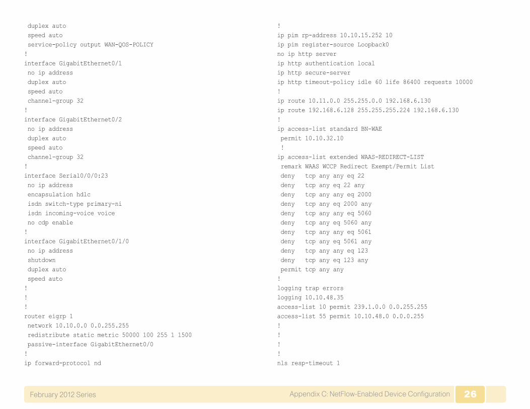
26Appendix C: NetFlow-Enabled Device ConfigurationFebruary 2012 Series
duplex auto speed auto service-policy output WAN-QOS-POLICY!interface GigabitEthernet0/1 no ip address duplex auto speed auto channel-group 32!interface GigabitEthernet0/2 no ip address duplex auto speed auto channel-group 32!interface Serial0/0/0:23 no ip address encapsulation hdlc isdn switch-type primary-ni isdn incoming-voice voice no cdp enable!interface GigabitEthernet0/1/0 no ip address shutdown duplex auto speed auto!!!router eigrp 1 network 10.10.0.0 0.0.255.255 redistribute static metric 50000 100 255 1 1500 passive-interface GigabitEthernet0/0!ip forward-protocol nd
!ip pim rp-address 10.10.15.252 10ip pim register-source Loopback0no ip http serverip http authentication localip http secure-serverip http timeout-policy idle 60 life 86400 requests 10000!ip route 10.11.0.0 255.255.0.0 192.168.6.130ip route 192.168.6.128 255.255.255.224 192.168.6.130!ip access-list standard BN-WAE permit 10.10.32.10 !ip access-list extended WAAS-REDIRECT-LIST remark WAAS WCCP Redirect Exempt/Permit List deny tcp any any eq 22 deny tcp any eq 22 any deny tcp any any eq 2000 deny tcp any eq 2000 any deny tcp any any eq 5060 deny tcp any eq 5060 any deny tcp any any eq 5061 deny tcp any eq 5061 any deny tcp any any eq 123 deny tcp any eq 123 any permit tcp any any!logging trap errorslogging 10.10.48.35access-list 10 permit 239.1.0.0 0.0.255.255access-list 55 permit 10.10.48.0 0.0.0.255!!!!nls resp-timeout 1

27Appendix C: NetFlow-Enabled Device ConfigurationFebruary 2012 Series
cpd cr-id 1!snmp-server community cisco RO 55snmp-server community cisco123 RW 55snmp-server ifindex persistsnmp-server source-interface informs Loopback0!control-plane!!voice-port 0/0/0:23!ccm-manager sccp local Port-channel32!!mgcp profile default!sccp local Port-channel32sccp ccm 10.10.48.21 identifier 2 priority 1 version 7.0 sccp ccm 10.10.48.20 identifier 1 priority 2 version 7.0 sccp!sccp ccm group 1 bind interface Port-channel32 associate ccm 2 priority 1 associate ccm 1 priority 2 associate profile 1 register CFBHQ1 switchback method graceful switchback interval 60!dspfarm profile 1 conference description HQ Conference Bridges codec g729br8 codec g729r8 codec g729abr8 codec g729ar8 codec g711alaw
codec g711ulaw codec g722-64 codec ilbc maximum sessions 5 associate application SCCP!dial-peer voice 100 voip description SIP TRUNK to CUCM1 preference 2 destination-pattern 230530.... session protocol sipv2 session target ipv4:10.10.48.20 incoming called-number . voice-class codec 1 !dial-peer voice 101 voip description SIP TRUNK to CUCM2 preference 1 destination-pattern 230530.... session protocol sipv2 session target ipv4:10.10.48.21 incoming called-number . voice-class codec 1 !dial-peer voice 911 pots destination-pattern 911 port 0/0/0:23 forward-digits 3!dial-peer voice 9911 pots destination-pattern 9911 port 0/0/0:23 forward-digits 3!dial-peer voice 7 pots destination-pattern 9[2-9]...... port 0/0/0:23

28Appendix C: NetFlow-Enabled Device ConfigurationFebruary 2012 Series
forward-digits 7!dial-peer voice 11 pots destination-pattern 91[2-9]..[2-9]...... port 0/0/0:23 forward-digits 11!dial-peer voice 9011 pots destination-pattern 9011T incoming called-number . direct-inward-dial port 0/0/0:23 prefix 011!!!!gatekeeper shutdown!!!line con 0line aux 0line 2 login local no activation-character no exec transport preferred none transport input all transport output lat pad telnet rlogin lapb-ta mop udptn v120 ssh stopbits 1line vty 0 4 exec-timeout 120 0 login local transport input ssh
line vty 5 15 login local transport input ssh!scheduler allocate 20000 1000ntp update-calendarntp server 10.10.48.17!end

Cisco has more than 200 offices worldwide. Addresses, phone numbers, and fax numbers are listed on the Cisco Website at www.cisco.com/go/offices.
Cisco and the Cisco Logo are trademarks of Cisco Systems, Inc. and/or its affiliates in the U.S. and other countries. A listing of Cisco's trademarks can be found at www.cisco.com/go/trademarks. Third party trademarks mentioned are the property of their respective owners. The use of the word partner does not imply a partnership relationship between Cisco and any other company. (1005R)
Americas HeadquartersCisco Systems, Inc.San Jose, CA
Asia Pacific HeadquartersCisco Systems (USA) Pte. Ltd.Singapore
Europe HeadquartersCisco Systems International BVAmsterdam, The Netherlands
SMART BUSINESS ARCHITECTURE
B-0000505-2 5/12