Application Instruction Manual -...
29
(English) HM-G.3.0.0-01 Application Instruction Manual (General Edition) Thank you for purchasing Shimano products. This instruction manual explains the operation of the E-TUBE PROJECT. Be sure to read this manual before use in order to fully utilize the functions. In order to use E-TUBE PROJECT, the SM-PCE1 or SM-BCR2 interface is required. Check the following support site for the latest support information. http://e-tubeproject.shimano.com
Transcript of Application Instruction Manual -...

(English) HM-G.3.0.0-01
Application Instruction Manual
(General Edition)
Thank you for purchasing Shimano products.
This instruction manual explains the operation of the E-TUBE PROJECT.
Be sure to read this manual before use in order to fully utilize the
functions.
In order to use E-TUBE PROJECT, the SM-PCE1 or SM-BCR2 interface is
required.
Check the following support site for the latest support information.
http://e-tubeproject.shimano.com
2 / 29
CONTENTS
INTRODUCTION ............................................................................................................................................ 3
ABOUT E-TUBE PROJECT ............................................................................................................................. 4
LINKS TO MANUALS (BY CATEGORY) ......................................................................................................... 5
CONNECTING THE SM-PCE1 ........................................................................................................................ 5
For normal connections ........................................................................................................................... 5
If there are no spare terminals ................................................................................................................ 6
If the cable is built in the frame .............................................................................................................. 7
HOW TO CONNECT SM-BCR2 ...................................................................................................................... 8
Connecting to the terminal section ........................................................................................................ 8
LAUNCHING AND CLOSING THE E-TUBE PROJECT ..................................................................................... 9
Launching the E-TUBE PROJECT .............................................................................................................. 9
Closing the E-TUBE PROJECT ................................................................................................................. 10
ABOUT THE E-TUBE PROJECT OPERATION SCREENS ................................................................................ 11
Bicycle selection screen .......................................................................................................................... 11
Main menu screen .................................................................................................................................. 12
Menu bar ................................................................................................................................................ 13
Menu screen ........................................................................................................................................... 15
Chart window ......................................................................................................................................... 16
EACH FUNCTION OF E-TUBE PROJECT ...................................................................................................... 18
Functions available in all series ............................................................................................................. 18
ABOUT THIS DOCUMENT .......................................................................................................................... 29
REGISTERED TRADEMARKS AND TRADEMARKS ...................................................................................... 29

INTRODUCTION
3 / 29
INTRODUCTION
This operating manual contains instructions for operating E-TUBE PROJECT.
In order to fully utilize the functions of E-TUBE PROJECT, please read this manual thoroughly before
use.
Note
Once a connection check is started, never connect or disconnect the battery or unit before the
completion of the operation or E-TUBE PROJECT. If this is not observed, it may damage the
SM-PCE1 / SM-BCR2 or the other units.
Never attempt to change the contents of the firmware files or the filenames. If you do this, it will
not be possible to update the firmware correctly, and problems may occur with the units after
carrying out firmware updates.
NOTE
When connecting the SM-PCE1 / SM-BCR2 to the PC, connect it directly to the USB port of the PC,
without using an intermediate device such as a USB hub.
Make sure that the PC does not switch into standby while you are carrying out operations such as
updating the firmware.
If the PC switches to standby, E-TUBE PROJECT processing will be interrupted and the screen
display will return to the main menu screen.
ABOUT E-TUBE PROJECT
4 / 29
ABOUT E-TUBE PROJECT
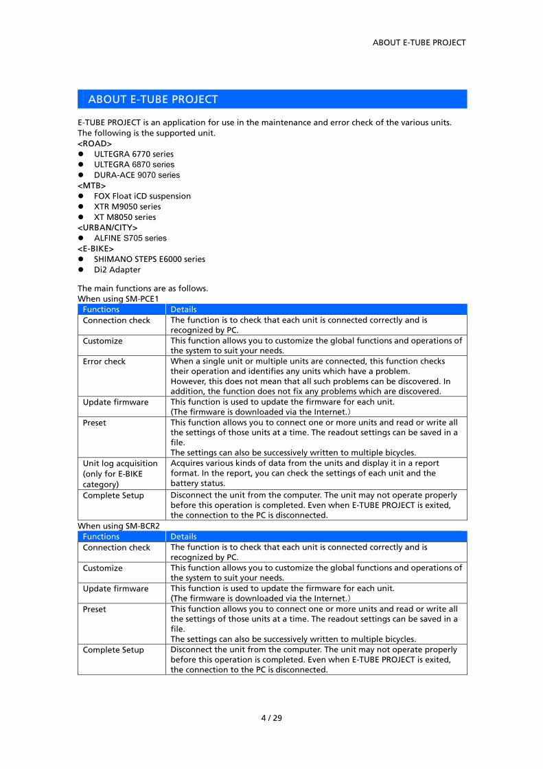
E-TUBE PROJECT is an application for use in the maintenance and error check of the various units. The following is the supported unit. <ROAD> ULTEGRA 6770 series ULTEGRA 6870 series DURA-ACE 9070 series <MTB> FOX Float iCD suspension XTR M9050 series XT M8050 series <URBAN/CITY> ALFINE S705 series <E-BIKE> SHIMANO STEPS E6000 series Di2 Adapter
The main functions are as follows. When using SM-PCE1
Functions Details Connection check The function is to check that each unit is connected correctly and is
recognized by PC. Customize This function allows you to customize the global functions and operations of
the system to suit your needs. Error check When a single unit or multiple units are connected, this function checks
their operation and identifies any units which have a problem. However, this does not mean that all such problems can be discovered. In addition, the function does not fix any problems which are discovered.
Update firmware This function is used to update the firmware for each unit. (The firmware is downloaded via the Internet.)
Preset This function allows you to connect one or more units and read or write all the settings of those units at a time. The readout settings can be saved in a file. The settings can also be successively written to multiple bicycles.
Unit log acquisition (only for E-BIKE category)
Acquires various kinds of data from the units and display it in a report format. In the report, you can check the settings of each unit and the battery status.
Complete Setup Disconnect the unit from the computer. The unit may not operate properly before this operation is completed. Even when E-TUBE PROJECT is exited, the connection to the PC is disconnected.
When using SM-BCR2 Functions Details Connection check The function is to check that each unit is connected correctly and is
recognized by PC. Customize This function allows you to customize the global functions and operations of
the system to suit your needs. Update firmware This function is used to update the firmware for each unit.
(The firmware is downloaded via the Internet.) Preset This function allows you to connect one or more units and read or write all
the settings of those units at a time. The readout settings can be saved in a file. The settings can also be successively written to multiple bicycles.
Complete Setup Disconnect the unit from the computer. The unit may not operate properly before this operation is completed. Even when E-TUBE PROJECT is exited, the connection to the PC is disconnected.

LINKS TO MANUALS (BY CATEGORY)
5 / 29
LINKS TO MANUALS (BY CATEGORY)
Click the following link to go to each category. ROAD MTB URBAN/CITY CITY/Trekking Other E-BIKE system
CONNECTING THE SM-PCE1
When connecting the SM-PCE1 to the PC, connect it directly to the USB port of the PC, without using
an intermediate device such as a USB hub.
For normal connections
Connect SM-PCE1 to an unused terminal section.

CONNECTING THE SM-PCE1
6 / 29
If there are no spare terminals
Disconnect one of the cables from the SM-JC40, and connect the SM-PCE1 in its place.

CONNECTING THE SM-PCE1
7 / 29
If the cable is built in the frame
Disconnect the cable from SM-EW67-A-E, mount SM-JC41 in its place, and connect SM-PCE1 to the
spare terminal.
* SM-JC41 to be added is separately required.
SM-JC41

HOW TO CONNECT SM-BCR2
8 / 29
HOW TO CONNECT SM-BCR2
When connecting SM-BCR2 to a PC, connect it to a USB port on the PC without using a USB hub or
other similar devices.
Connecting to the terminal section
LAUNCHING AND CLOSING THE E-TUBE PROJECT
9 / 29
LAUNCHING AND CLOSING THE E-TUBE PROJECT
Launching the E-TUBE PROJECT
After installing E-TUBE PROJECT, double-click the E-TUBE PROJECT shortcut icon on the desktop which
was created during the installation procedure.
If the PC is connected to the Internet after bicycle selection, the update information of E-TUBE
PROJECT and the firmware of each component is checked. The latest information on E-TUBE PROJECT
can be obtained at any time.

LAUNCHING AND CLOSING THE E-TUBE PROJECT
10 / 29
Launching requirements
In order to use E-TUBE PROJECT, the SM-PCE1 / SM-BCR2 must be connected to the PC.
When the SM-PCE1 / SM-BCR2 connection request dialog box is displayed, connect the
SM-PCE1 / SM-BCR2 to the PC using the USB cable.
Closing the E-TUBE PROJECT
Select [Exit] from the [File] menu on the menu bar. Alternatively, click the close button in the
top-right corner of the application screen.
When the Exit confirmation dialog box is displayed, click [OK] to close E-TUBE PROJECT.
* E-TUBE PROJECT cannot be closed while firmware updating is still in progress.

ABOUT THE E-TUBE PROJECT OPERATION SCREENS
11 / 29
ABOUT THE E-TUBE PROJECT OPERATION SCREENS
Bicycle selection screen
Refer to the following manual for the operating procedures when using a single unit connection.
HM-SP.3.0.0-01.pdf
Select the bicycle type used or single unit connection.
1. Bicycle type
2. Single unit connection
1
2

ABOUT THE E-TUBE PROJECT OPERATION SCREENS
12 / 29
Main menu screen
When a bicycle is selected, the main menu screen will be displayed. The main menu screen is
comprised of the following 1 to 3.
1. Menu bar
2. Menu screen
3. Chart window
(Main menu screen)
2 3
1

ABOUT THE E-TUBE PROJECT OPERATION SCREENS
13 / 29
Menu bar
This contains the various operations that are carried out by the E-TUBE PROJECT.
File
Exit
This closes E-TUBE PROJECT.
Setting
Application settings
Configure the Exit confirmation dialog setting that is used when E-TUBE PROJECT is exited.
Change the settings in the [Application settings] dialog.
Click [OK] to exit application settings.
Language setting
Set the language to use in E-TUBE PROJECT.
When you change the language, the Re-launch confirmation dialog box will be displayed.
Change the language setting and click [Yes]. E-TUBE PROJECT is then automatically restarted.
If you click [No], the language will be changed the next time you launch E-TUBE PROJECT.
You can select from the following languages.
• English
• French
• German
• Dutch
• Spanish
• Italian
• Chinese
• Japanese
*Depending on the selected vehicle type, the desired language may not be available. In that case,
English is used as the language of the screen text.

ABOUT THE E-TUBE PROJECT OPERATION SCREENS
14 / 29
Help
Manual help
This displays the E-TUBE PROJECT manual (this document).
E-TUBE PROJECT latest version check
This function checks whether an updated version of E-TUBE PROJECT is available for downloading.
When a new version is available, the following screen will be displayed. When [Yes] is selected, the
latest version of E-TUBE PROJECT will be downloaded. After that, follow the on-screen instructions to
carry out the upgrade.
* The PC needs to be connected to the Internet for this check to be carried out.
If your E-TUBE PROJECT is the latest version, check whether a new version of the firmware of each
component has been released. When a new version is available, it will be automatically downloaded.
* When there is no firmware that can be downloaded, the message will be displayed.
The firmware files which have been downloaded will be stored in the following folders.
Firmware can be updated even on a PC that is not connected to the Internet by copying the firmware
files.
These folders are created automatically when the E-TUBE PROJECT is installed.
These folders are hidden. To display them, the Windows settings need to be changed.
Version Save destination
Windows Vista C:¥ProgramData¥E-tube Project¥FW
Windows 7 C:¥ProgramData¥E-tube Project¥FW
Windows 8 C:¥ProgramData¥E-tube Project¥FW
Windows 10 C:¥ProgramData¥E-tube Project¥FW
* Never attempt to change the contents of the firmware files or the filenames. If you do
this, it will not be possible to update the firmware correctly, and problems may occur
with the units after carrying out firmware updates.
ABOUT THE E-TUBE PROJECT OPERATION SCREENS
15 / 29
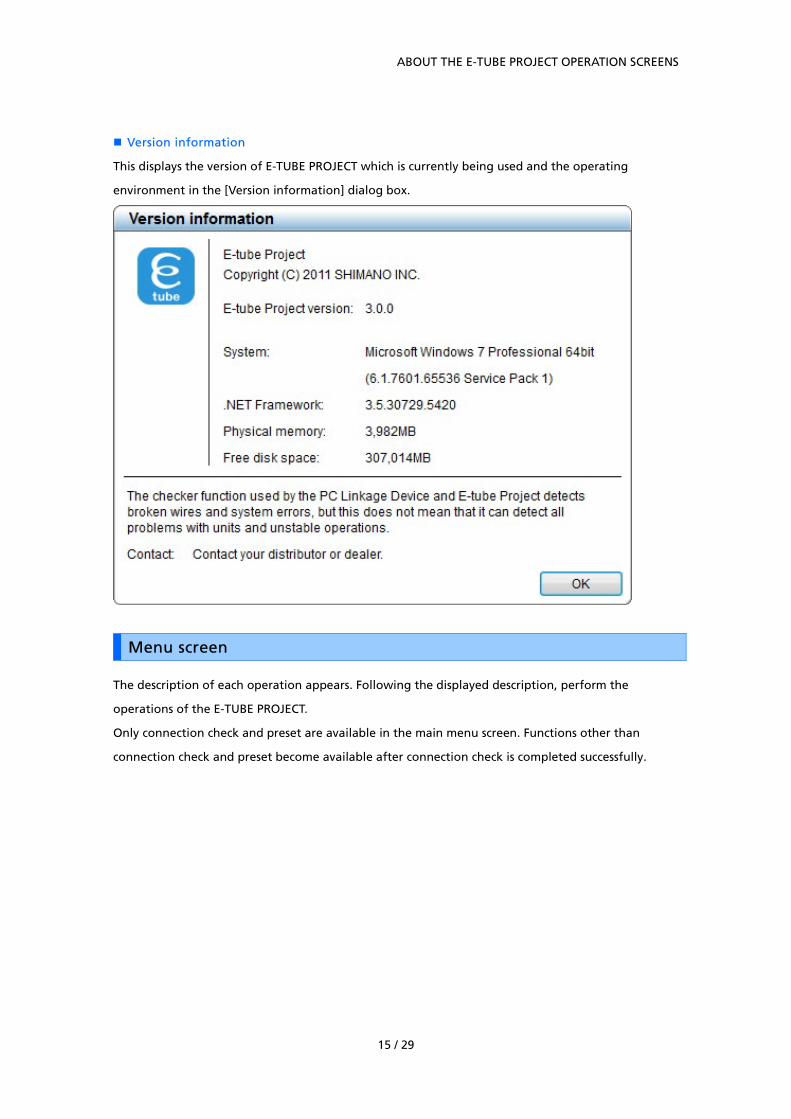
Version information
This displays the version of E-TUBE PROJECT which is currently being used and the operating
environment in the [Version information] dialog box.
Menu screen
The description of each operation appears. Following the displayed description, perform the
operations of the E-TUBE PROJECT.
Only connection check and preset are available in the main menu screen. Functions other than
connection check and preset become available after connection check is completed successfully.

ABOUT THE E-TUBE PROJECT OPERATION SCREENS
16 / 29
Chart window
This screen shows the unit status and data while the E-TUBE PROJECT is being used.
Unit status
The statuses of connected units are displayed in the chart.
The unit status displays are as follows.
View Unit status
Illuminated green box Connected
Flashing green box Selected
Flashing green Processing
Illuminated green Processing result: Normal
Flashing red Processing result: Problem
Illuminated yellow Firmware update available

ABOUT THE E-TUBE PROJECT OPERATION SCREENS
17 / 29
Unit data
The following data for the units which are connected is extracted and displayed.
If you click on the icon for a unit, the unit name (model number) and firmware version for that unit
will be displayed.
* The box containing this data can be moved by dragging it with the mouse.
EACH FUNCTION OF E-TUBE PROJECT
18 / 29
EACH FUNCTION OF E-TUBE PROJECT
Functions available in all series
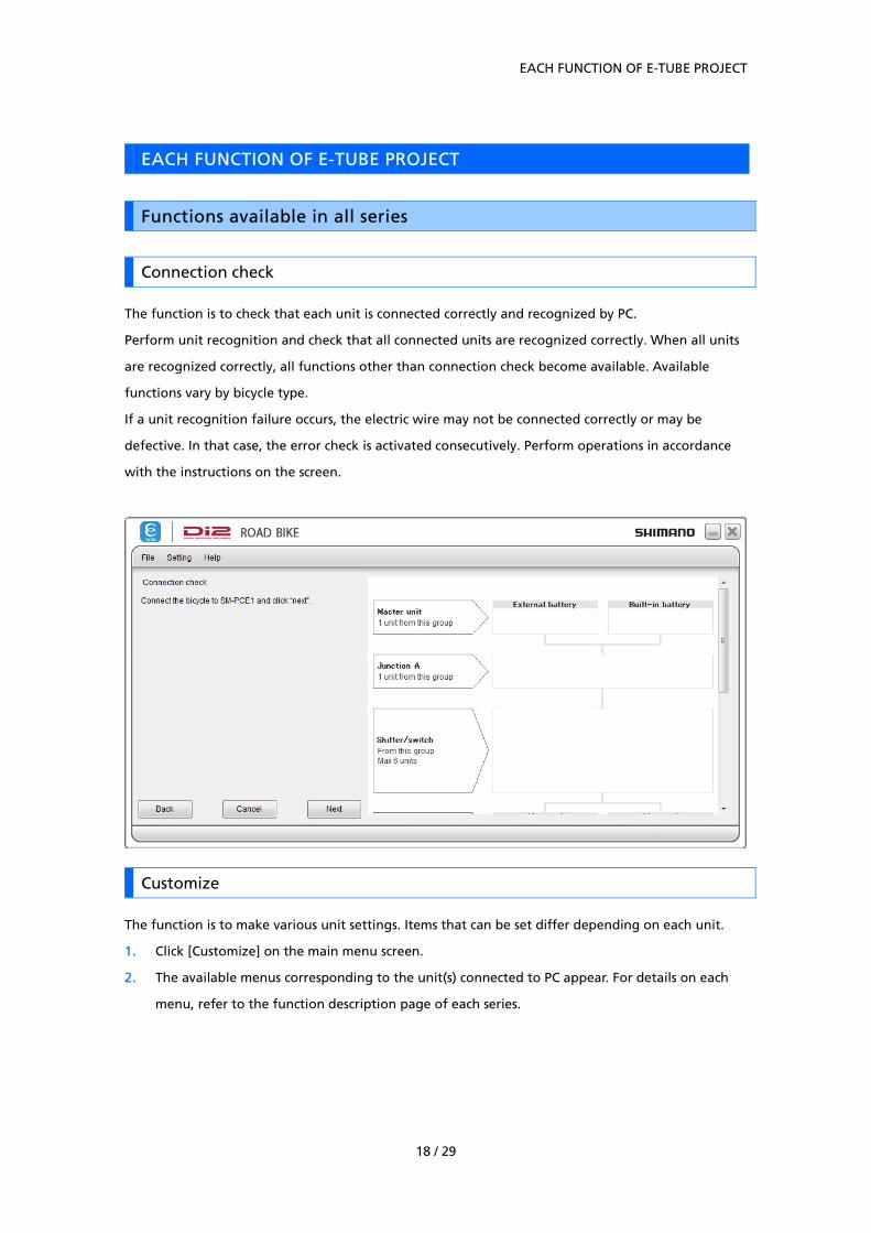
Connection check
The function is to check that each unit is connected correctly and recognized by PC.
Perform unit recognition and check that all connected units are recognized correctly. When all units
are recognized correctly, all functions other than connection check become available. Available
functions vary by bicycle type.
If a unit recognition failure occurs, the electric wire may not be connected correctly or may be
defective. In that case, the error check is activated consecutively. Perform operations in accordance
with the instructions on the screen.
Customize
The function is to make various unit settings. Items that can be set differ depending on each unit.
1. Click [Customize] on the main menu screen.
2. The available menus corresponding to the unit(s) connected to PC appear. For details on each
menu, refer to the function description page of each series.

EACH FUNCTION OF E-TUBE PROJECT
19 / 29
Error check
When a single unit or multiple units are connected, this function checks their operation and identifies
any units which have a problem.
Click [Error check] in the main menu screen to move to the error check screen.
Select the unit where its error check is performed and click [Start diagnosis]. The error check of the
selected unit is started. Perform operations following the instructions on the screen.
(Error check screen)
* If you click [Skip], the diagnosis operations for the unit which is currently being diagnosed
will be skipped.
The diagnosis statuses displayed on the screen for each unit are as follows.
Diagnosis status Description
[Waiting for
judgment]
Units for which diagnosis has not yet started
[Diagnosis in
progress...]
Unit for which diagnosis is in progress
[Skip] Units for which diagnosis has been skipped
[Normal] Units with no problems detected in diagnosis
[May have a
problem]
Units for which the diagnosis result shows a possible problem

EACH FUNCTION OF E-TUBE PROJECT
20 / 29
Updating firmware
This function is used to update the firmware for each unit.
* The firmware is downloaded via the Internet.
1. To start updating the firmware, click [Update firmware] in the main menu screen.
2. In the unit selection screen, select the unit of which firmware is updated, and then click
[Update].
(Unit selection screen)
3. In the compatibility confirmation screen, check for unit firmware compatibility with the latest
firmware and then click [Next].
For latest firmware compatibility refer to the following manual.
HM-CC.3.0.0-01.pdf

EACH FUNCTION OF E-TUBE PROJECT
21 / 29
4. In the update content confirmation screen, check the content to be updated, and click [Update].
The update statuses displayed in the screen are as follows.
Update status Description
[Waiting for
update]
Units for which updating has not yet started
[Updating in
progress...]
Unit for which updating is in progress
[Normal end] Units for which updating ended normally
* Make sure that the PC does not switch into standby while updating of the firmware is in
progress.
If the PC switches to standby, E-TUBE PROJECT processing will be interrupted and the screen
display will return to the main menu screen.
* Do not disconnect the USB cable or the electric wires, remove the battery or turn off the
power for the PC while updating of the firmware is in progress.
* When connecting the battery to carry out firmware updating, make sure that the battery is
sufficiently charged so that it does not run out of charge while updating of the firmware is in
progress.
* If you click the [Cancel] button, updating of the firmware will be canceled. However, it will
not be canceled until updating of the firmware for the current unit has finished.
* You cannot shut down the application while updating of the firmware is in progress.
5. When updating of the firmware is complete, the firmware update complete screen will be
displayed, and the names of the units which were updated and their firmware versions will also
be displayed.
If an error occurs while updating firmware
If an error occurs during updating of the firmware, an error screen will be displayed.
The unit may not operate properly when it has failed to update the firmware. Do not use the unit in
that condition. Follow the on-screen instructions to restore the firmware.

EACH FUNCTION OF E-TUBE PROJECT
22 / 29
Preset
What is preset?
This section gives a brief explanation of the concept of preset.
* Detailed operating procedures are explained starting from the next page.
Flowchart
Edit setup
Manually create a setting
file
Reading the settings from
the bicycle
Reading a setting file
Save
Writing on the
bicycle's setting file
Bicycle
HDD (PC)
Setting review
You
Writing on the
bicycle's setting file
・Import the previously saved
settings file
Reading a setting file
Save
Reading the settings
from the bicycle
・Read the setting file from
the connected bicycle
・Allows you to choose the items to be set
Manually create a setting file

EACH FUNCTION OF E-TUBE PROJECT
23 / 29
This function allows you to connect one or more units and read or write all the settings of those units
at a time.
Preset can be performed before connection check.
Manually create a setting file
Select [Manually create a setting file] from the preset menu to manually configure setting items.
First, select a unit configuration of the bicycle in the screen below. You do not need to connect the
units.
Units that do not require setting are not displayed on the list.

EACH FUNCTION OF E-TUBE PROJECT
24 / 29
Then, set each item.
Clicking [Save] saves the setting file.
Clicking [Writing on the bicycle's setting file] saves the setting file and starts writing the settings to
the bicycle. In this case, connect the bicycle to be set before clicking [Writing on the bicycle's setting
file].

EACH FUNCTION OF E-TUBE PROJECT
25 / 29
Reading the settings from the bicycle
Select [Reading the settings from the bicycle] from the preset menu to read settings from the
connected bicycle.
When you read settings, the following screen appears.
Clicking [Save] saves the setting file.
Clicking [Writing on the bicycle's setting file] saves the setting file and starts writing the settings to
the bicycle. In this case, connect the bicycle to be set before clicking [Writing on the bicycle's setting
file].
Clicking [Changing settings] changes the settings.

EACH FUNCTION OF E-TUBE PROJECT
26 / 29
Reading a setting file
Select [Reading a setting file] from the preset menu to read a previously saved setting file.
When you select a file, the following screen appears.
If the displayed settings are correct, click [Writing on the bicycle's setting file]. After you are
prompted accordingly on the screen, writing starts.
Clicking [Changing settings] changes the settings.
EACH FUNCTION OF E-TUBE PROJECT
27 / 29
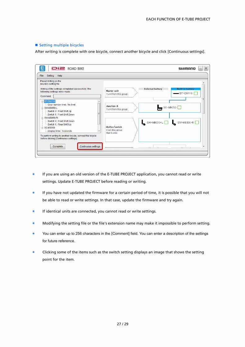
Setting multiple bicycles
After writing is complete with one bicycle, connect another bicycle and click [Continuous settings].
* If you are using an old version of the E-TUBE PROJECT application, you cannot read or write
settings. Update E-TUBE PROJECT before reading or writing.
* If you have not updated the firmware for a certain period of time, it is possible that you will not
be able to read or write settings. In that case, update the firmware and try again.
* If identical units are connected, you cannot read or write settings.
* Modifying the setting file or the file's extension name may make it impossible to perform setting.
* You can enter up to 256 characters in the [Comment] field. You can enter a description of the settings
for future reference.
* Clicking some of the items such as the switch setting displays an image that shows the setting
point for the item.
EACH FUNCTION OF E-TUBE PROJECT
28 / 29
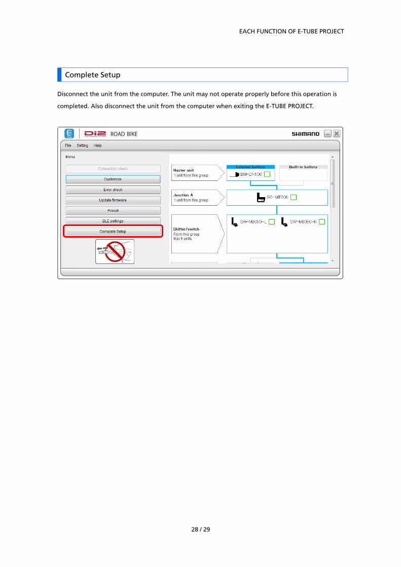
Complete Setup
Disconnect the unit from the computer. The unit may not operate properly before this operation is
completed. Also disconnect the unit from the computer when exiting the E-TUBE PROJECT.

ABOUT THIS DOCUMENT
29 / 29
ABOUT THIS DOCUMENT
The contents of this document are subject to revision in the future without notice.
Reproducing or transmitting this document in whole or in part in any form or for any purpose
whatsoever without the express written permission of SHIMANO INC. is expressly forbidden. However,
this is not to be taken as a limit on the customer’s rights under applicable copyright laws.
SHIMANO INC. may own the rights to any patents, patent applications, trademarks, copyrights and
any other intangible property rights contained in this document. Unless otherwise specified, the
customer is not granted rights to any patents, trademarks, copyrights or any other intangible
intellectual property contained in this document.
REGISTERED TRADEMARKS AND TRADEMARKS
Shimano is a trademark or registered trademark of SHIMANO INC. in Japan and other countries.
is a trademark of SHIMANO, INC. in Japan and other countries.
Microsoft®, Windows Vista TM, Windows® 7, Windows® 8, Windows® 10 are registered trademarks or
trademarks of Microsoft Corporation in the United States of America and other countries.
All other company names, product names and service names, etc. are the property of their respective
owners.
Please note: specifications are subject to change for improvement without notice. (English)
One Holland, Irvine, California 92618, U.S.A. Phone: +1-949-951-5003
Industrieweg 24, 8071 CT Nunspeet, The Netherlands Phone: +31-341-272222
3-77 Oimatsu-cho, Sakai-ku, Sakai-shi, Osaka 590-8577, Japan


![Help Manual - Shimanoe-tubeproject.shimano.com/pdf/en/HM-EO.3.3.0-00-EN.pdf · * During this operation, ... [OFF] in [Other Shifting Switch]. [Gear-shifting interval] The gear-shifting](https://static.fdocuments.in/doc/165x107/5abdf0ba7f8b9a8e3f8c6455/help-manual-shimanoe-during-this-operation-off-in-other-shifting-switch.jpg)