
Application Guide M-0245C High Speed Sync-Check …€“3– M-0245C High Speed Sync-Check Relay...
26
Application Guide M-0245C High Speed Sync-Check Relay
Transcript of Application Guide M-0245C High Speed Sync-Check …€“3– M-0245C High Speed Sync-Check Relay...
Application Guide
M-0245C High SpeedSync-Check Relay
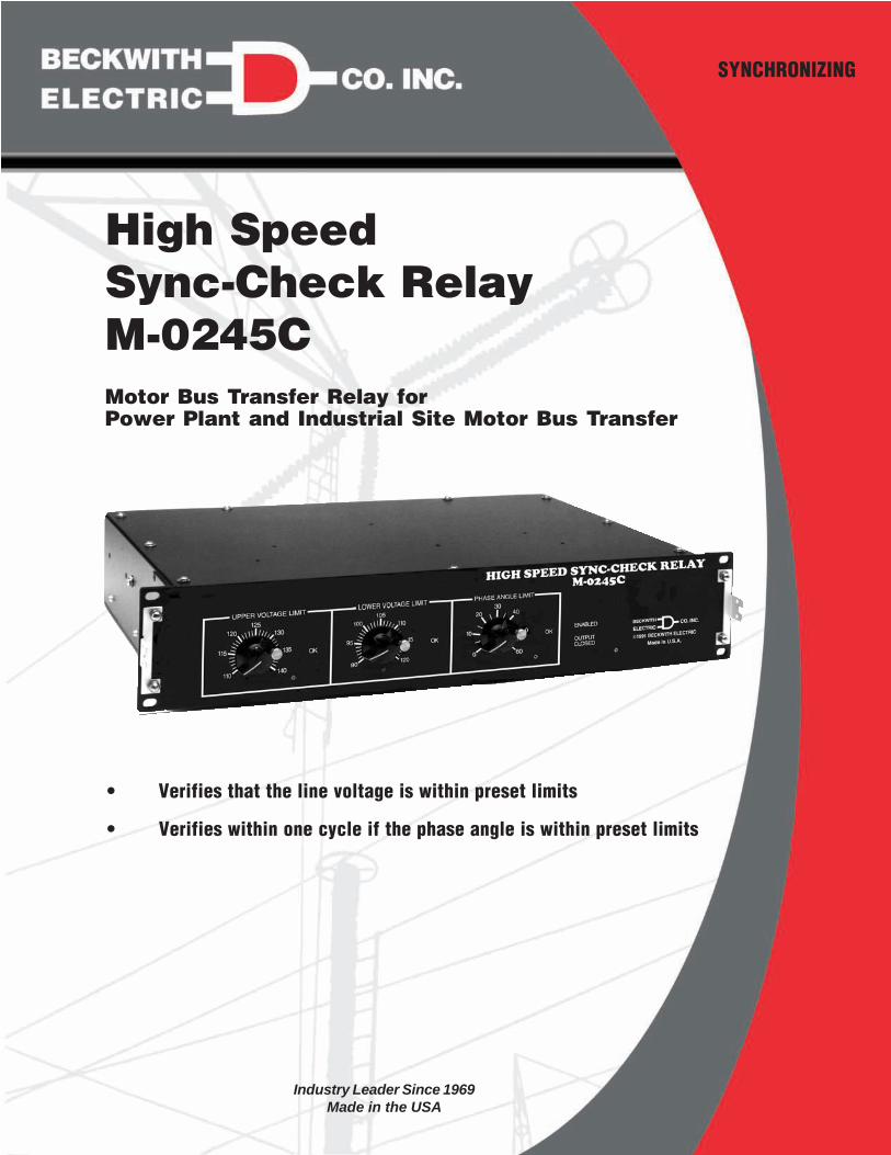
• Verifies that the line voltage is within preset limits
• Verifies within one cycle if the phase angle is within preset limits
SYNCHRONIZING
High SpeedSync-Check RelayM-0245CMotor Bus Transfer Relay forPower Plant and Industrial Site Motor Bus Transfer
Industry Leader Since 1969Made in the USA

–2–
M-0245C High Speed Sync-Check Relay
High speed transfer of auxiliary services at a generating plant or the motor load in an industrial plant is highlydesirable to prevent either damage to critical motors or an unplanned shutdown.
A significant induced voltage will remain at the terminals of a rotating machine for a period of time followingremoval of power. If, during the power transfer sequence, the phase angle of this voltage relative to the auxiliarysource is ignored, severe damage to an expensive machine or process may result. The M-0245C High SpeedSync-Check Relay provides the means necessary to inhibit transfer if the phase angle is excessive or the linevoltage is out of range.
InputsMotor Bus Voltage: 120 V ac nominal
Line Voltage: 120 V ac nominal
M-0245C Supply: 120 V ac ±10%, 60 to 400 Hz
External Dry Contact Closure: Enables the synchronizing verification. This contact should be designed for lowvoltage, low current signals.
NOTE: All voltage inputs are isolated. The supply input and auxiliary source may be connected togetherexternally, provided the voltage transformer from this auxiliary supply has sufficient capacity.
BurdenMotor Bus Voltage: 0.15 VA burden
Line Voltage: 0.15 VA burden
M-0245C Supply: 12 VA burden
ControlsUPPER VOLTAGE LIMIT for Line Voltage: 110 to 140 V ac
LOWER VOLTAGE LIMIT for Line Voltage: 90 to 120 V ac
PHASE ANGLE LIMIT: Ranges are available from 0 to 180°, 0 to 120°, 0 to 60°, or 0 to 30°
NOTE: Accurately calibrated dials facilitate field adjustment without additional test equipment.
LED IndicatorsUPPER VOLTAGE LIMIT - OK: Line voltage is less than the upper voltage limit setting.
LOWER VOLTAGE LIMIT - OK: Line voltage is greater than the lower voltage limit setting.
PHASE ANGLE LIMIT OK: Phase difference between the Line and Bus voltage inputs is less than the phaseangle limit setting.
ENABLED: The external enable contact, rear terminal TB1-20 to TB1-21, is closed.
OUTPUT CLOSED: The solid-state output circuit, rear terminal TB2-A to TB2-B, is closed.
Breaker Close RelaySolid-state Breaker Close Circuit is capable of making and breaking an inductive current of 15 A at 300 V dc. Theclosing signal will remain until the enable contact is opened, provided phase angle and voltage remain withinpreset limits.
Response TimeDelay after power turn on: Approximately 2 sec. Output will be open during this period, regardless of otherinputs.
Delay after closing enable input: 1/4 cycle. Output will be open until the M-0245C is enabled, regardless ofother inputs.

–3–
M-0245C High Speed Sync-Check Relay
Delay after voltage change in or out of band: Generally ranges from 0 to 0.08 sec. Refer to the M-0245CApplication Guide for further details.
Maximum delay after phase change in or out of band: 1 cycle
Status Relay ContactsLine Source Voltage OK: Contact is closed when the voltage is within the upper and lower voltage limit settings.
Phase Angle OK: Contact is closed when the phase angle between the Line and Motor Bus voltage inputs iswithin the phase angle limit setting.
Analog OutputsPhase Difference: 0 to 180° corresponding to 0 to 10 V dc (55.6 mV per degree)
Line Source Voltage: 0 to 140 V ac input corresponding to 0 to 7 V dc output
Motor Bus Source Voltage: 0 to 140 V ac input corresponding to 0 to 7 V dc output
NOTE: Each analog output has an output impedance of 10 K referenced to rear terminal TB1-7. These outputsare suitable for use with existing or future supervisory control systems.
ReliabilityThe M-0245C High Speed Sync-Check Relay is assembled on a single glass-epoxy printed circuit board, therebyeliminating the need for plug-in connectors. All semiconductor components are hermetically sealed and of thehighest and most reliable quality available. Highly stable instrument grade capacitors and resistors are used incritical measurement circuits to minimize the possibility of error.
Transient ProtectionAll inputs and outputs are fully transient protected and will pass the ANSI C37.90.1-1989 Surge WithstandCapability (SWC) Test. The Motor Bus and Line Input Voltages, Status Relay outputs, 120 V ac Power input andBreaker Close Circuit output will withstand 1500 V ac, 60 Hz to chassis or instrument ground for one minute.Voltage inputs are electrically isolated from each other, from other circuits and from ground.
NOTE: Use of varistor suppressors across contacts and from contacts to chassis ground is suggested ifthese contacts are to be tied to long wire runs.
Harmonic FiltersMany applications for the M-0245C High Speed Sync-Check Relay will involve power systems which incorporateloads such as variable speed drives, arc furnaces and converters which produce harmonics on the system. TheM-0245C includes active filters on the bus and line voltage inputs to permit proper operation in these applications.
EnvironmentalTemperature Range: Units will operate properly over a temperature range of –40° to +80° C.
Humidity: Stated accuracies are maintained under 95% relative humidity (non-condensing).
Fungus Resistance: A conformal printed circuit board coating inhibits fungus growth.
Seismic: Units are designed to meet extreme shock and vibration requirements.

BECKWITH ELECTRIC CO., INC.6190 - 118th Avenue North • Largo, Florida 33773-3724 U.S.A.
PHONE (727) 544-2326 • FAX (727) [email protected]
www.beckwithelectric.comISO 9001:2008
800-0245C-SP-01MC2 01/13© Beckwith Electric Co. All RIghts Reserved.Printed in U.S.A. (04.24.01)
PhysicalSize: 19" wide x 3-1/2" high x 13" deep (48.3 cm x 8.9 cm x 33.0 cm). Requires two rack units space in astandard 19" rack. May also be panel-mounted horizontally or vertically.
Approximate Weight: 15 lbs (6.8 kg)
Approximate Shipping Weight: 20 lbs (9.1 kg)
The M-0245C includes a transparent cover to protect the knobs and prevent accidental resetting.
PatentsThe M-0245C High Speed Sync-Check Relay is covered by U.S. Patents 4,218,625 and 4,256,972.
WarrantyThe M-0245C High Speed Sync-Check Relay is covered by a five year warranty from date of shipment.
The Specification is subject to change without notice.

��������������� ������������������������������� ��!���!������"�!#���!���!���������� ���$��!������!%������������������ ���&���'%���(�����$�!�%�������������������)����������#�!�����) ��� ��'����������������!���"�������� ���&���%���(�*�)�+�!��� ��������!���+���������+�����!������!����!�� ���� ��+�������������������� ���$��!'������!%�����(
DANGER! HIGH VOLTAGE
– This sign warns that the area is connected to a dangerous high voltage, and youmust never touch it.
PERSONNEL SAFETY PRECAUTIONSThe following general rules and other specific warnings throughout the manual must be followed during application,test or repair of this equipment. Failure to do so will violate standards for safety in the design, manufacture, and intendeduse of the product. Qualified personnel should be the only ones who operate and maintain this equipment. BeckwithElectric Co., Inc. assumes no liability for the customer’s failure to comply with these requirements.
– This sign means that you should refer to the corresponding section of the operation
manual for important information before proceeding.
Always Ground the Equipment
To avoid possible shock hazard, the chassis must be connected to an electrical ground. When servicingequipment in a test area, the Protective Earth Terminal must be attached to a separate ground securelyby use of a tool, since it is not grounded by external connectors.
Do NOT operate in an explosive environmentDo not operate this equipment in the presence of flammable or explosive gases or fumes. To do so wouldrisk a possible fire or explosion.
Keep away from live circuitsOperating personnel must not remove the cover or expose the printed circuit board while power is ap-plied. In no case may components be replaced with power applied. In some instances, dangerous volt-ages may exist even when power is disconnected. To avoid electrical shock, always disconnect power anddischarge circuits before working on the unit.
Exercise care during installation, operation, & maintenance proceduresThe equipment described in this manual contains voltages high enough to cause serious injury or death.Only qualified personnel should install, operate, test, and maintain this equipment. Be sure that all per-sonnel safety procedures are carefully followed. Exercise due care when operating or servicing alone.
Do not modify equipmentDo not perform any unauthorized modifications on this instrument. Return of the unit to a BeckwithElectric repair facility is preferred. If authorized modifications are to be attempted, be sure to followreplacement procedures carefully to assure that safety features are maintained.
PRODUCT CAUTIONSBefore attempting any test, calibration, or maintenance procedure, personnel must be completely familiarwith the particular circuitry of this unit, and have an adequate understanding of field effect devices. If acomponent is found to be defective, always follow replacement procedures carefully to that assure safetyfeatures are maintained. Always replace components with those of equal or better quality as shown in theParts List of the Instruction Book.
Avoid static chargeThis unit contains MOS circuitry, which can be damaged by improper test or rework procedures. Careshould be taken to avoid static charge on work surfaces and service personnel.
Use caution when measuring resistancesAny attempt to measure resistances between points on the printed circuit board, unless otherwise notedin the Instruction Book, is likely to cause damage to the unit.

TABLE OF CONTENTSM-0245C High Speed Sync-Check Relay
Application Guide
1.0 Introduction ................................................................................................................... 1
2.0 Application .................................................................................................................... 1Motor Bus Transfer ....................................................................................................... 1Figure 1 Typical Motor Bus System ........................................................................... 1Parallel Transfer ............................................................................................................ 1Sequential Transfer ....................................................................................................... 1Figure 2 Sequential Transfer: Sync-Check Permissive ............................................... 2Figure 3 Sequential Transfer: Sync-Check Blocking Due to Excessive Initial Phase . 3Figure 4 Sequential Transfer: Excessive Rate of Change of Phase ........................... 4
2.1 Input Loss Protection .................................................................................................... 5Operating with Harmonic Producing Loads .................................................................... 5Operating with Inductive Loads ..................................................................................... 5Figure 5 Recommended Connections for Inductive Loads .......................................... 5Figure 6 Block Diagram .............................................................................................. 6
3.0 Mounting ....................................................................................................................... 7Figure 7 Mounting: Outline Dimensions for all Syncrocloser Equipment Chassis ....... 7Figure 8 Mounting: Panel Cutout Dimensions ............................................................. 8Figure 9 External Connections .................................................................................... 9
4.0 Adjustment ................................................................................................................. 10Figure 10 Front Panel Controls ................................................................................. 10
5.0 Performance ............................................................................................................... 10Response to Phase Angle Change .............................................................................. 10Phase Limit Setting Variation ...................................................................................... 10Figure 11 Phase Limit Setting Variation: Bus Frequency (Typical) ........................... 11Figure 12 Phase Angle Limit Setting Variation: Voltage (Typical) ............................. 11Voltage Circuit Response ............................................................................................ 12Figure 13 Voltage Circuit Response.......................................................................... 12
6.0 Maintenance ............................................................................................................... 13
© Beckwith Electric Co. All Rights Reserved.Printed in U.S.A. (07.30.01) 800-0245C-AG-00MC6 01/13

This Page Left Intentionally Blank

–1–
M-0245C Application Guide
1.0 Introduction
The Beckwith Electric M-0245C High SpeedSync-Check Relay is a solid-state device used formotor bus transfer. It is specifically designed torespond to changes in the phase angle between themotor bus voltage and the alternate source voltage.When the alternate voltage input is within the UPPERand LOWER VOLTAGE LIMIT dial settings, and thephase angle between the alternate voltage and themotor bus voltage is less than that set on the PHASEANGLE LIMIT dial, the M-0245C will permit breakerclosing. If the phase angle exceeds this control setting,the unit will block closing within two cycles. Forexample, if the limit is 30°, the unit will inhibit closingwithin two cycles of the time when the phase angleexceeded 30°. If the phase angle returns within the30° limit, the unit will enable closing within two cycles.
2.0 Application
Motor Bus TransferFigure 1, a typical motor bus system, below, is asimplified one-line diagram.
M MM
G
GENERATORSTEP-UPTRANSFORMER
MAINSOURCETRANSFORMER
ALTERNATESOURCETRANSFORMER
BUS
MOTOR
TRANSMISSION SYSTEM
Figure 1 Typical Motor Bus System
While the generating plant is operating normally, thepower required by the motor bus would be suppliedby the main source transformer. However, with thisconfiguration, motor bus system power must besupplied from a separate source during the unitstart-up/shut-down sequences, and whenevertransmission or generator fault clearing is required.During these periods, the alternate (auxiliary) sourcetransformer must be connected to supply motor bussystem power. This process of exchanging powersources is commonly referred to as a motor bustransfer.
Synchronism check supervision of parallel andsequential bus transfers greatly increases the reliabilityof each transfer method.
Parallel TransferParallel transfer involves closing the alternate sourcebreaker before the main source breaker is opened.This method parallels the sources for a brief periodallowing the motor bus system a continuous sourceof power.
Parallel transfer should be blocked during out ofphase or fault conditions, otherwise excessive dutycan be imposed upon the associated switchgear andtransformer. High speed synchronism verification canact as a “permissive device” during parallel transfers.This device must be capable of precise high speedphase measurement independent of voltage,frequency and environmental conditions. Also, sincethe device is acting under a permissive role, theoutput contact current interrupting capability is justas important as the contact closing capability.
Sequential TransferIn contrast to parallel transfer schemes, sequentialtransfer involves closing the alternate source breakerafter the main source breaker is opened. This methodassures that main and alternate sources are notparalleled.
Sequential transfers must be blocked for out of phaseconditions but need not be blocked for fault conditionsbecause the sources are not paralleled. However,the out of phase condition must include worst caseconditions on initial phase and motor bus decelerationas well as breaker closing time.
Figure 2, Sequential Transfer: Sync-CheckPermissive, although exaggerated, illustrates howmotor bus deceleration can affect the sequentialtransfer.
Øsc
is the sync-check relay phase setting.
Øt
is the phase when the actual transfertakes place.
Øm
is the maximum safe transfer phaseangle for a given motor bus system.
In Figure 2, Øt exceeds Ø
sc by a considerable margin
because after initiating closing of alternate sourcebreaker, the phase of the motor bus continues tomove with respect to the alternate source until thealternate source breaker closes.

M-0245C Application Guide
–2–
Øsc
Ø t
Ø m
MAIN SOURCE BREAKER OPENS
ALTERNATE SOURCE BREAKERCLOSING INITIATED
ALTERNATE SOURCEBREAKER CLOSES
ALTERNATE SOURCEBREAKER CLOSING TIME
TIME
0
PH
AS
E
Figure 2 Sequential Transfer: Sync-Check Permissive
Knowing the highest rate of change of the motor busphase and the alternate source breaker closing time,calculations can be made to determine the propersync-check phase setting Øsc. This particular sync-check phase Ø
sc setting can block a sequential
transfer should the initial phase or rate of phasechange be excessive.
Figures 3 and 4 illustrate this approach. Sequentialtransfer would be blocked in Figure 3, SequentialTransfer: Sync-Check Blocking Due to ExcessiveInitial Phase, because the initial phase exceeds thesync-check phase setting Ø
sc. If transfer were
permitted, the actual transfer phase Øt exceeds the
maximum safe transfer phase and possible damageto the motor bus or associated equipment wouldresult. Also in Figure 4, Sequential Transfer:Excessive Rate of Change of Phase, sequentialtransfer would be blocked because the rate of phasechange is excessive. The motor bus phase exceedsthe sync-check phase setting Ø
sc before the alternate
source breaker is initiated; thus the sync-check relayblocks the sequential transfer.

–3–
M-0245C Application Guide
Øsc
Ø m
Ø t
MAIN SOURCE BREAKER OPENS
ALTERNATE SOURCE BREAKERCLOSING INITIATED
ALTERNATE SOURCEBREAKER CLOSES
TIME
0
PH
AS
E
ALTERNATE SOURCEBREAKER CLOSING TIME
INITIAL PHASE
Figure 3 Sequential Transfer: Sync-Check Blocking Due to Excessive Initial Phase

M-0245C Application Guide
–4–
Øsc
Ø m
Ø t
MAIN SOURCE BREAKER OPENS
ALTERNATE SOURCE BREAKERCLOSING INITIATED
ALTERNATE SOURCEBREAKER CLOSES
0
PH
AS
E
ALTERNATE SOURCEBREAKER CLOSING TIME
INITIALPHASE
TIME
Figure 4 Sequential Transfer: Excessive Rate of Change of Phase

–5–
M-0245C Application Guide
Figure 4, Sequential Transfer: Excessive Rate ofChange of Phase, illustrates the need for sync-checkverification when the motor bus is isolated. Verificationbefore the main source breaker opens does not provideany information about how the motor bus phasebehaves when isolated unless the verification extendsinto the isolated bus region (i.e., the sync-check relayverifies the phase when the motor bus is isolated).
The previously mentioned requirements for async-check relay demands a high speed precisionphase measurement which is independent of voltage,frequency or environmental conditions.
For sync-check supervision of parallel or sequentialtransfers the Beckwith M-0245C High SpeedSync-Check Relay provides the necessary high speedprecision phase measurement with performanceessentially independent of the above parameters.
2.1 Input Loss Protection
The M-0245C has been designed with an Input LossProtection circuit to minimize the possibility of theoutput contacts closing due to the sudden loss of theV.T. input sources. The circuitry provides the followingprotection features in addition to those afforded bythe UPPER and LOWER VOLTAGE LIMIT settingson the front panel controls:
1. The M-0245C output contact is forced tothe normally open state for any of thefollowing conditions:a. Sudden drop in the line VT voltage
magnitude.
b. Sudden drop in the bus VT voltagemagnitude.
c. Bus V.T. voltage less than 0.25 PU
2. Rate of change of phase, as detected bythe M-0245C circuitry, is greater than 2900degrees/sec. (8 Hz frequency difference.)
The possibility still remains, however, that under certainconditions (i.e., loose wires causing an intermittentcontact) the internal circuitry may not be able todetect the loss and the output contact could closewhen the unit is initiated. Therefore, as a safeguard,the “Enable Sync Check” contact from terminals TB1-20to 21 should be closed only during the time requiredfor supervision of the transfer sequence to becompleted.
Operating with Harmonic Producing LoadsMany applications for the High Speed Sync-CheckRelay will involve power systems which incorporateloads such as variable speed drives, arc furnaces andconverters which produce harmonics on the system.The M-0245C includes active filters on the bus andline voltage inputs to permit proper operation in theseapplications.
Operating with Inductive LoadsThe solid-state Breaker Close Circuit is fully protectedfrom transients and inductive spikes. However, it isstrongly recommended when driving highly inductiveloads to use the “transient suppressor diode” withinthe M-0245C for added suppression. This diode isavailable from rear terminal C. See Figure 5, below.The typical application will illustrate the most effectiveuse of this diode.
With this connection, the M-0245C output is capableof safely opening 15 A of current in a breaker closesolenoid with a battery voltage up to 300 V dc.
INDUCTIVELOAD
BATTERYPOSITIVE
BATTERYNEGATIVEB
A
C
M-0
245C
Rea
r T
erm
inal
s
Figure 5 Recommended Connectionsfor Inductive Loads

M-0245C Application Guide
–6–
LOW
ERVO
LTAG
EC
OM
PAR
ATO
R
HIG
H-S
PEED
PHAS
EM
EASU
RIN
GN
ETW
OR
K
1 V/
18°
RAT
E O
FC
HAN
GE
OF
Ø >
290
0°/s
ec
BUS
UN
DER
-VO
LTAG
ED
ETEC
TOR
<25%
INPU
T LO
SSD
ETEC
TOR
LOG
ICN
ETW
OR
K
OPT
ICAL
SOLI
D-S
TATE
BREA
KER
CLO
SEN
ETW
OR
K
TRAN
SIEN
T
ISO
LATE
DPO
WER
SUPP
LY
BREA
KER
CLO
SEO
UTP
UT
TRAN
SIEN
TPR
OTE
CTI
ON
120
VAC
60 H
z
POW
ERSU
PPLY
MO
NIT
OR
ACTI
VEAC
to D
CC
ON
VER
TER
BUFF
ERAM
PLIF
IER
ENAB
LESY
NC
-CH
ECK
INPU
T
BUS
VOLT
AGE
ANAL
OG
OU
TPU
T1
V/20
V a
c
PHAS
E AN
GLE
CO
MPA
RAT
OR
PHAS
E O
K
1 V/
20 V
ac
BLO
CK
CLO
SIN
G
STEP
-DO
WN
ISO
LATI
ON
TRAN
SFO
RM
ER
MO
TOR
BUS
INPU
TTR
ANSI
ENT
PRO
TEC
TIO
N
ACTI
VEAC
to D
CC
ON
VER
TER
UPP
ERVO
LTAG
EC
OM
PAR
ATO
R
MAI
NPO
WER
SUPP
LYN
ETW
OR
K
LIN
E VO
LTAG
EAN
ALO
G O
UTP
UT
1 V/
20 V
ac
1 V/
20 V
ac
INPU
T LO
SSD
ETEC
TOR
LIN
EIN
PUT
TRAN
SIEN
TPR
OTE
CTI
ON
STEP
-DO
WN
ISO
LATI
ON
TRAN
SFO
RM
ER
VAR
IABL
ESP
EED
MO
TOR
VAR
IABL
ESP
EED
MO
TOR
PHAS
E AN
GLE
ANAL
OG
OU
TPU
T
Figure 6 Block Diagram
–7–
M-0245C Application Guide
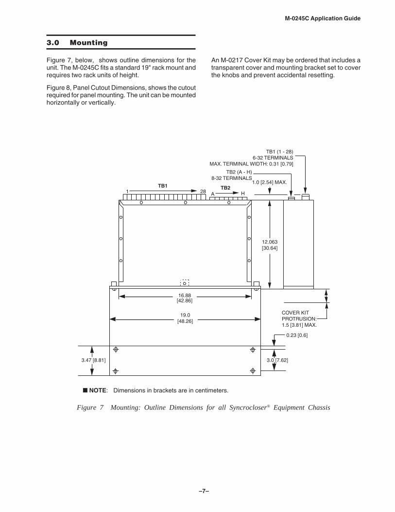
3.0 Mounting
Figure 7, below, shows outline dimensions for theunit. The M-0245C fits a standard 19" rack mount andrequires two rack units of height.
Figure 8, Panel Cutout Dimensions, shows the cutoutrequired for panel mounting. The unit can be mountedhorizontally or vertically.
An M-0217 Cover Kit may be ordered that includes atransparent cover and mounting bracket set to coverthe knobs and prevent accidental resetting.
1.0 [2.54] MAX.
12.063[30.64]
� NOTE: Dimensions in brackets are in centimeters.
1 28 A H
19.0[48.26]
COVER KITPROTRUSION:1.5 [3.81] MAX.
TB2 (A - H)8-32 TERMINALS
TB1 (1 - 28)6-32 TERMINALS
MAX. TERMINAL WIDTH: 0.31 [0.79]
TB1 TB2
16.88[42.86]
0.23 [0.6]
3.0 [7.62]3.47 [8.81]
Figure 7 Mounting: Outline Dimensions for all Syncrocloser® Equipment Chassis

M-0245C Application Guide
–8–
8.67[22.07]
0.281 [0.71]DIA. HOLES
4 PLACES
9.16[23.26]
8.67[22.07]
9.16[23.26]
1.72[4.37]
1.5[3.81]
1.72[4.37]
1.5[3.81]
■ NOTE: Dimensions in brackets are in centimeters
Figure 8 Panel Cutout Dimensions
–9–
M-0245C Application Guide
Motor Bus Voltage Analog Output
0 Volts
Enable Sync-Check Input
0 Volts
281
AH
TB
1T
B2
1
2
3
4
5
6
7
8
9
10
11
12
13
14
15
16
17
18
19
20
21
22
23
24
25
26
27
28
A
B
C
D
H
+-
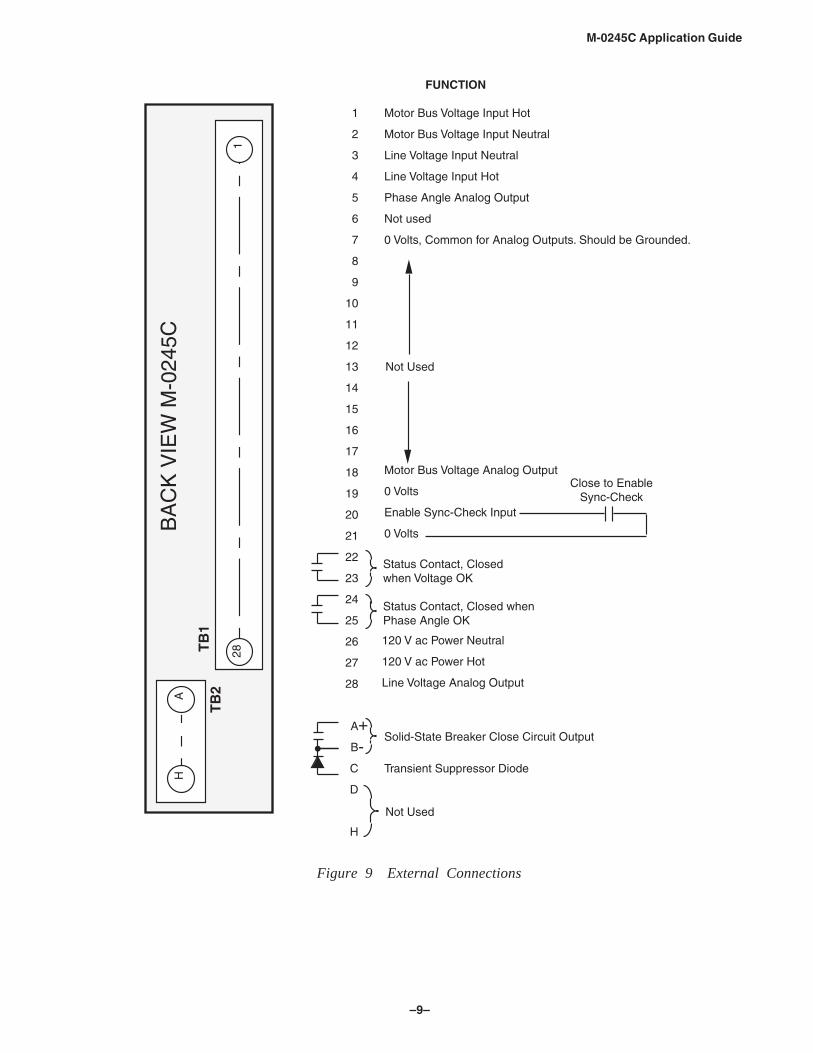
Motor Bus Voltage Input Hot
Motor Bus Voltage Input Neutral
Line Voltage Input Neutral
Line Voltage Input Hot
Phase Angle Analog Output
Not used
0 Volts, Common for Analog Outputs. Should be Grounded.
Not Used
Status Contact, Closedwhen Voltage OK
Status Contact, Closed whenPhase Angle OK
120 V ac Power Neutral
120 V ac Power Hot
Line Voltage Analog Output
Solid-State Breaker Close Circuit Output
Not Used
Transient Suppressor Diode
FUNCTION
Close to EnableSync-Check
BA
CK
VIE
W M
-024
5C
Figure 9 External Connections
M-0245C Application Guide
–10–
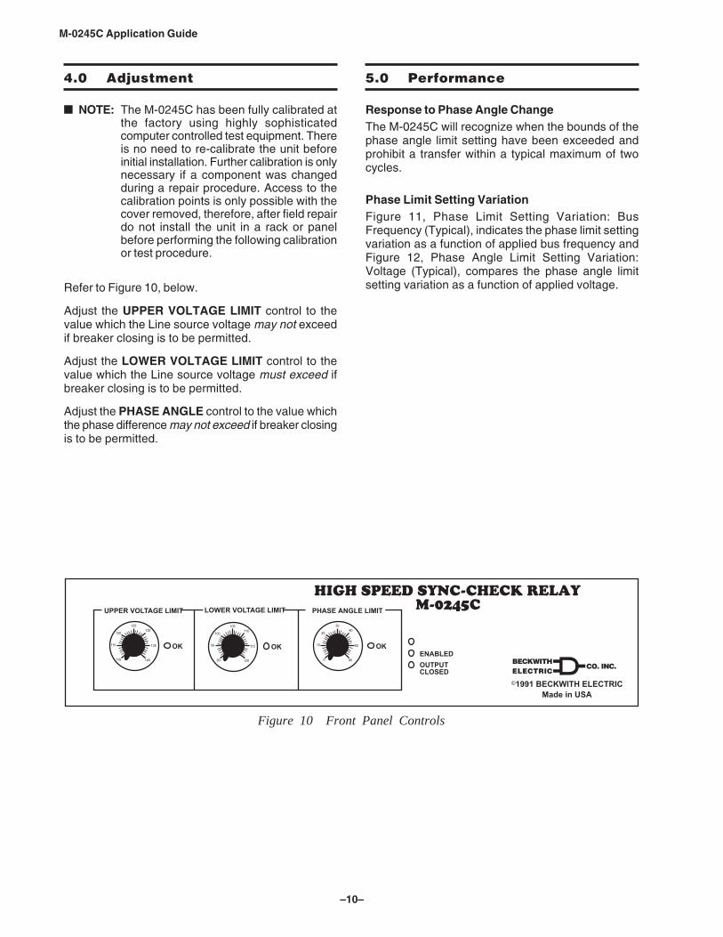
4.0 Adjustment
NOTE: The M-0245C has been fully calibrated atthe factory using highly sophisticatedcomputer controlled test equipment. Thereis no need to re-calibrate the unit beforeinitial installation. Further calibration is onlynecessary if a component was changedduring a repair procedure. Access to thecalibration points is only possible with thecover removed, therefore, after field repairdo not install the unit in a rack or panelbefore performing the following calibrationor test procedure.
Refer to Figure 10, below.
Adjust the UPPER VOLTAGE LIMIT control to thevalue which the Line source voltage may not exceedif breaker closing is to be permitted.
Adjust the LOWER VOLTAGE LIMIT control to thevalue which the Line source voltage must exceed ifbreaker closing is to be permitted.
Adjust the PHASE ANGLE control to the value whichthe phase difference may not exceed if breaker closingis to be permitted.
5.0 Performance
Response to Phase Angle ChangeThe M-0245C will recognize when the bounds of thephase angle limit setting have been exceeded andprohibit a transfer within a typical maximum of twocycles.
Phase Limit Setting VariationFigure 11, Phase Limit Setting Variation: BusFrequency (Typical), indicates the phase limit settingvariation as a function of applied bus frequency andFigure 12, Phase Angle Limit Setting Variation:Voltage (Typical), compares the phase angle limitsetting variation as a function of applied voltage.
������������� ����������� �����
�������������� ����������������
�������� ����� �� ������ ����� �� ��������� �� ��
��
���
���
������
���
���
���
��
���
���
������
���
��
��
��
�
��
����
��
��
����� ��
������� ����
Figure 10 Front Panel Controls

–11–
M-0245C Application Guide
VLINE = VBUS = 120V
Phase Angle Limit Setting = 30O
0O
0.5O
SE
TP
OIN
T E
RR
OR
(D
EG
RE
ES
)
54 55 56 57 58 59 60 61 62
BUS FREQUENCY
Figure 11 Phase Limit Setting Variation: Bus Frequency (Typical)
1.0o
0.5o
1.5o
.5o
0o
-0.5o
30 60 90 120 120
BUS VOLTAGE
10°
20°30°
40°50°,60°
PHASE ANGLE LIMIT SETPOINT
VLINE = 120 V
SE
TP
OIN
T E
RR
OR
(D
EG
RE
ES
)
Figure 12 Phase Angle Limit Setting Variation: Voltage (Typical)

M-0245C Application Guide
–12–
Voltage Circuit ResponseThe graph in Figure 13, below can be used to determinehow fast the M-0245C voltage circuitry will respond tochanges in the input level. The curve is drawn to allowuse with any step change in the input voltage amplitudewhether positive or negative. The time delay can bedetermined for any step change by knowing thefollowing:
1. Initial voltage amplitude
2. Final voltage amplitude
3. Voltage level setting (UPPER/LOWERVOLTAGE LIMIT).
Example 1:The input drops from 120 V ac to 60 V ac with aLOWER VOLTAGE LIMIT of 90 V ac:
Vstep
= 120 – 60 = 60 V ac
Lower Limit = 90 V ac
TIME (SEC)
ΔVS
TE
P (
%)
EX. 2
EX. 1
= VSTEP100
50
.05 .1 .15
Figure 13 Voltage Circuit Response
The graph of Figure 13 shows that a 50% ΔVstep
levelis achieved in .036 seconds (2.2 cycles).
Example 2:
The input is suddenly applied at 120 V ac with aLOWER VOLTAGE LIMIT setting of 90 V ac.
Vstep
= 120 – 0 = 120 V ac
ΔVstep% = 0–90 X 100 = 75%
120
From the chart T = 0.054 seconds (3.24 cycles).
�� ���� ������������� �������� �� ������� �
�������� ���������
������������

–13–
M-0245C Application Guide
6.0 Maintenance
Due to the extremely sophisticated nature of thecircuitry in the M-0245C, field repair is notrecommended. All units are fully calibrated at thefactory prior to shipment; there is no need torecalibrate a unit prior to initial installation. Calibrationis only required after a component is replaced.
▲ CAUTION: Do not reverse polarity of the VTleads to the rear terminal block if the unit is taken outof service for maintenance.
In the event that a unit does not operate properly, itshould be established that the problem is caused bymalfunction of a Beckwith unit and not caused by anexternal fault or wiring error.
Once this is determined, the entire unit should bereturned to Beckwith Electric Co. Pack the unitcarefully (in the original carton if possible), assuringthat there is adequate packing material to protect thecontents.
NOTE: Any equipment returned for repair must besent with transportation charges prepaid.The equipment must remain the propertyof the user. The warranty is void if thevalue of the unit is invoiced to BeckwithElectric at the time of return or if the unit isreturned with transportation charges collect.
If under warranty, units will be repaired rapidly andreturned at no cost and with return transportationpaid if the fault is found to be due to workmanship orfailure of material.
If a unit is under warranty and express shipment forreturn of the repaired unit is requested, shippingcharges will be billed at the current rate. If the fault isdue to abuse or misuse, or if the unit is out ofwarranty, a modest charge will be made. Repair cannormally be expected to take two weeks, plus shippingtime. If faster service is required, it should be requestedat the time of return.
To help in analyzing the problem, a completedescription of the malfunction and conditions leadingto the failure should be included with the unit.
However, if you choose to repair the unit, it isnecessary to be completely familiar with the circuitryinvolved, and have an adequate understanding offield effect devices. Be sure to carefully read theWARNING page at the beginning of this manual.
To gain access to the circuit board, remove the topand bottom cover of the unit. Components can thenbe easily tested or changed. It is suggested that firsta visual inspection be made for any component thatdoes not appear normal or appears to haveoverheated. Analysis of the circuit will then often leadto the cause of the failure and components that needto be replaced.
If no obvious problems exist, it is suggested that thetest and calibration procedures in the M-0245CInstruction Book be followed until a portion of a circuitis detected which does not perform as expected oruntil a calibration point is found which will not meetrequirements. These procedures should lead to adetermination of the defective component.

M-0245C Application Guide
–14–
This Page Left Intentionally Blank

Legal Information
PatentThe units described in this manual are covered byU.S. Patents, with other patents pending.
Buyer shall hold harmless and indemnify the Seller,its directors, officers, agents, and employees fromany and all costs and expense, damage or loss,resulting from any alleged infringementof UnitedStates Letters Patent or rights accruing thereform ortrademarks, whether federal, state, or common law,arising from the Seller’s compliance with Buyer’sdesigns, specifications, or instructions.
WarrantySeller hereby warrants that the goods which are thesubject matter of this contract will be manufacturedin a good workmanlike manner and all materialsused herein will be new and reasonably suitable forthe equipment. Seller warrants that if, during aperiod of five years from date of shipment of theequipment, the equipment rendered shall be foundby the Buyer to be faulty or shall fail to peform inaccordance with Seller’s specifications of theproduct, Seller shall at his expense correct thesame, provided, however, that Buyers shall ship theequipment prepaid to Seller’s facility. The Seller’sresponsibility hereunder shall be limited to replace-ment value of the equipment furnished under thiscontract.
Seller makes no warranties expressed or impliedother than those set out above. Seller specificallyexcludes the implied warranties of merchantibilityand fitness for a particular purpose. There are nowarranties which extend beyond the descriptioncontained herein. In no event shall Seller be liable forconsequential, exemplary, or punitive damages ofwhatever nature.
Any equipment returned for repair must be sentwith transportation charges prepaid. The equipmentmust remain the property of the Buyer. The afore-mentioned warranties are void if the value of theunit is invoiced to the Seller at the time of return.
IndemnificationThe Seller shall not be liable for any propertydamages whatsoever or for any loss or damagearising out of, connected with, or resulting fromthis contract, or from the performance or breachthereof, or from all services covered by or furnishedunder this contract.
In no event shall the Seller be liable for special,incidental, exemplary, or consequential damages,including but not limited to, loss of profits orrevenue, loss of use of the equipment or anyassociated equipment, cost of capital, cost ofpurchased power, cost of substitute equipment,facilities or services, downtime costs, or claims ordamages of customers or employees of the Buyerfor such damages, regardless of whether said claimor damages is based on contract, warranty, tortincluding negligence, or otherwise.
Under no circumstances shall the Seller be liablefor any personal injury whatsoever.
It is agreed that when the equipment furnishedhereunder are to be used or performed in connec-tion with any nuclear installation, facility, oractivity, Seller shall have no liability for anynuclear damage, personal injury, property damage,or nuclear contamination to any property located ator near the site of the nuclear facility. Buyer agreesto indemnify and hold harmless the Seller againstany and all liability associated therewith whatso-ever whether based on contract, tort, or otherwise.Nuclear installation or facility means any nuclearreactor and includes the site on which any of theforegoing is located, all operations conducted onsuch site, and all premises used for such opera-tions.
Notice:Any illustrations and descriptions by BeckwithElectric Co., Inc. are for the sole purpose ofidentification.
The drawings and/or specifications enclosed hereinare the proprietary property of Beckwith ElectricCo., Inc., and are issued in strict confidence;therefore, shall not be used as a basis of reproduc-tion of the apparatus described therein withoutwritten permission of Beckwith Electric Co., Inc.
No illustration or description contained hereinshall be construed as an express warranty ofaffirmation, promise, description, or sample, andany and all such express warranties are specificallyexcluded nor shall such illustration or descriptionimply a warranty that the product is merchantableor fit for a particular purpose. There shall be nowarranties which extend beyond those contained inthe Beckwith Electric Co., Inc. terms of sale.
All rights reserved by Beckwith Electric Co., Inc. No reproduction may be made without prior written approvalof the Company.

This Page Left Intentionally Blank

BECKWITH ELECTRIC CO., INC.6190 - 118th Avenue North • Largo, Florida 33773-3724 U.S.A.
PHONE (727) 544-2326 • FAX (727) [email protected]
www.beckwithelectric.comISO 9001:2008
© Beckwith Electric Co. All Rights Reserved.Printed in USA 800-0245-AG-00MC6 01/13