Powell, Clapp (2009) Using Large-Scale Testing Diagnostically

NAVORD REPOR T 6771
APPLICATION OF THE van der POL
EQUATION4 TO OSCILLATOR-DESIGN
A ILI~NCE
Umis AVALORANNCIUBORTTAR
WHT AMRLN
atA
I. M. L't

NAVORD REPORT 6771
APPLICATION OF THE van der POL
EQUATION TO OSCILLATOR DESIGN
Prepared by:
L. R. Hirschel
ABSTRACT: While the results obtained using the van der Polequation are generally applicable to all vacuum-tube osci'.ators,there remains the problem of predicting the behavior ofparticular oscillator types and determining the effects of thevarious parameters on operability. To this end the van der Polequation has been applied to the Hartley, Colpitts, and grounded-grid Colpitts (with autotransformer antenna coupling) oscillatortypes. Formulas are obtained in terms of the pertinent parameters,for equilibrium amplitude, time constant of amplitude build-up,sensitivity to coherent interference, and noise side-bands. Theeffect of antenna coupling on these quantities is determined. Theresults obtained are useful with either grid or plate detectionsystems.
Published March 1960
U. S. NAVAL ORDNANCE LABORATORYWHITE OAK, MARYLAND
i
NAVORD REPORT 6771 22 December 1959
This report presents an analysis from a mathematical point of
view of those quan-ities pertinent to vacuum-tube oscillatoroperability. The material is intended as a guide in thedesign of oscillators.
The work was performed under authorization of task numberNOL-357.
JOHN A. QUENSE'Captain, USNCommander. Acting
s: j. AFFBy direction
Vk
V

NAVORD REPORT 6771
CONTENTS
Page
Introduction 1 e * * n . . . . . . . . . . . . . . . . . .Elementary Considertios... * V **.....1
Negative Resistance . ......... . . . . . . . . . . . ... . 2The Equivalent Circuit . . . . . . . . . . . . . . . . . . . 2Oscillation Build-Up . .Forcing5Solution with Coherent ocin uci ..... ..... 6Noise Considerations . . . . .. . .. .. . .. . 8Autotransformer Antenna Coupling . . . . . . . . . . . . . . 8r ~ ~ Narrow-Band Noise . . . . . .. ... .... . .. 9Differential Equation with Noise Source. .... . ..... 9Signal-to-Noise Ratio. . . . . . . . . . . . . . . . . . . .12Summary. . . . . . . . . . . . . . . . . . . . . . . . . . .13Appendix A . . . . . . . . . . . . . . . . . . . 14
ILLUSTRATIONS
Figure 1. Oscillator with Negative Resistance Element. 17Figure 2a. Circuit Diagram of Hartley Oscillator. 17Figure 2b. Circuit Diagram of Colpitts Oscillator. 17Figure 3. Family of Plate Characteristics Showing Path
of Operation. 18Figure 4a. Equivalent Circuit of Hartley Oscillator. 18Figure 4b. Equivalent "ircuit of Colpitts Oscillator. 18Figure 5. Equivalent Circuit of Grounded-Grid Colpitts
Oscillator with Autotransformer Coupler. 19Figure 6. Appearance of Narrow-Band Noise. 19

NAVORD REPORT 6771
APPLICATION OF THE van der POL
EQUATION TO OSCILLATOR DESIGN
INTRODUCTION
1. Oscillators may be classed in many different ways.Examples of such classifications are to be found in theliterature and are characterized by such terms as negative-resistance, feedback, relaxation, etc. Many oscillator typesare associated with the name of the inventor, as Hartley,Colpitts, Clapp, Franklin, Meissner, etc. Such classificationshave the merit of characterizing the configurations so thatthey may be distinguished from one-another. However, from amathematical point of view, it may be said that all oscillatorsare negative-resistance oscillators. While this--unifyingviewpoint may not be as familiar as the classifications justcited, It is one to be cultivated since the basis of a morethorough understanding of oscillators depends on adoptingJust such a viewpoint.
Elementary Considerations
2. The viewpoint Just expressed can be made reasonablefrom elementary considerations. Consider the L-C-R circuitof Figure 1 in shunt with an elementIp whose characteristicwe shall determine. It may be readily shown that thedifferential equation for such a circuit is given by
T C (e R) oat L O (C
the solution of equation (1) is given by the relation
7{v-=AeCoo*_In order that oscillations build up, it is necessary that theexponent in equation (2) assume a positive value. This canonly be so if the quantity. is negative, and
Having by some means or other achieved a value of negativeresistance consistent with equation (3), it becomes clear that
44

NAVORD REPORT 6771
while oscillations will build up, they cannot do soindefinitely. Thus the linear differential equation whichwas used to determine the starting condition gives noinformation about the equilibrium value of amplitude. However,as is well known, vacuum tube oscillators are capable oflimiting the amplitude of oscillation. The implication isthen that while a negative resistance is necessary for thestart of oscillations, the characteristic supplying the negativeresistance can only be negative over a limited region. Thelimiting action of a vacuum tube oscillator has been adequatelyexplained by van der Pol in reference (a) by suitably modifyingequation (I). The modified equation is a second-order non-
j 1linear differential equation called van der Pol's Equation.While the results given by van der Pol are generallyapplicable to all oscillators, there remains the problem ofpredicting the behavior in particular oscillator types anddetermining the effect of the various parameters onoperability. To this end van der Pol's Equation will be appliedto two oscillator types commonly employed; the Hartley andColpitts types. The circuits for these oscillators are shownin Figure 2.
Negative Resistance in Vacuum 'ibes
3. it may be shown that the dynamic characteristic of anoscillator can be determined from the static family of platecharacteristics for a triode. Briefly it may be stated, thatto the extent that the family of plate characteristics areparallel to one antoher, t e plate curren t may be madedependent on the quantityj ZVA, where, . is a functipn ofthe a plification factor 1an the excitation ratio suchht h -I, and VA is'the alternating plate voltage.
/T, is cetermined by the circuitry external to the tu~e, andmay be positive or negative. For positive values ofJ thedynamic characteristic takes the form of a cubic equation whoseslope at the origin is negative. Figure 3 shows the form of astatic characteristic. Temperature-limited emission partlyaccounts for the upper limit of current. Also shown areseveral dynamic characteristics, with the excitation ratio asa parameter. The curvature of the characteristic at the topand bottom is such as to cause amplitude limiting.
The Equivalent Circuit
4. Consider the oscillator circuits shown in Figure 2.The equivalent circuits of these oscillators are shown inFigure 4. A sufficient number of elements are shown toemphasize the essential features of operation withoutdestroying the semblance of reality. The antenna impedanceis considered to be entirely resistive; the grid circuit,inductors and capacitors are considered lossless, so that
2
NAVORD REPORT 6771
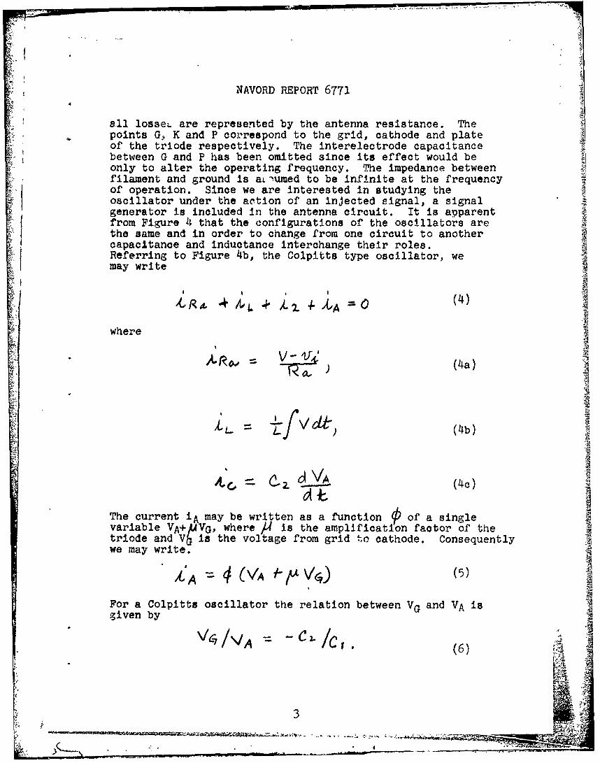
all losse4 are represented by the antenna resistance. Thepoints G. K and P correspond to the grid, cathode and plateof the triode respectively. The interelectrode capacitancebetween G and P has been omitted since its effect would beonly to alter the operating frequency. The impedance betweenfilament and ground is al umed to be infinite at the frequencyof operation. Since we are interested in studying theoscillator under the action of an injected signal, a signalgenerator is included in the antenna circuit. It is apparentfrom Figure 4 that the configurations of the oscillators arethe same and in order to change from one circuit to anothercapacitance and inductance interchange their roles.Referring to Figure 4b, the Colpitts type oscillator, wemay write
iA
where
AirD
-- V-.- (4a)
C1V
c(4c)
The current iA may be written as a function 0 of a singlevariable VA+ 4VG, where A4 is the amplification factor of thetriode and Vbis the voltage from grid to cathode. Consequentlywe may write.
kA(V ~ fr'V~)(5)
For a Colpitts oscillator the relation between VG and VA isgiven by
C2,/C-• ,(6)
3

NAVORD REPORT 6771
SC/cis called the "excitation ratio". A third relationa netingV, VA and V is immediately obvious from Figure 4_5 and is givef by
V VA 46. (7)
Substituting for VC in equation (5) the value given inequation (6) we may write
iA PEVA VAf (8)
Substituting equations (4a), (4b), (4c), (6) and (7) intoequation (1) and differentiating, the result is given by
va,+ +VA c Cl. Avgd4()
The assunption is made as in reference (a) that the relationbetweenLA and VA (negative characteristic - see Fi.gure 3)may be represented by a cubic equation so that
)-A OVA + YV4o (10)
The subscript 0 indicates the derivatives are evaluated at the
operating point. Using equation (10), equation (9) becomes
0( Q-- YL~ "13 W ¢
~A~OVA SAALY'' ~ (1
where + the -C1
C,4 C% C,4- L-
Equation (11) is a second-order non-linear difterentialequation called van der Po1's Equation. It is equallyI. * applicable to the Hartley oscillator if the followingrelations are employed:
4
4 - -

NAVORD REPORT 6771
S-L J- r k flA_C. C n + nI- -- W"Y ' y OA
LC r0+nC
'~RA A thThe limiting effects are accounted for in equation (11) by adamping term proportional to VAZ. The normal form ofvan der Pol's Equation is generally given by
0" ==.UA 0( Go
The coefficient E determines the nature of the oscillations.For 2 the oscillations are essentially harmonic, for Er7the oscillations depart markedly from a sine wave and arecharacterized by the term "relaxation oscillations".
Oscillation Build-Up
5. Consider equation (11) with the forcing function setequal to zero. With the aid of the solution for equation (12)
given in reference (a) the solution for equation (11) isgiven by the relation
• _ __ _ _ _~~~
where \4/3 ~~V
is the amplitude of the free oscillation as t-CO. 4 'takesaccount of the oscillation phase at time t. In arriving atequation (13) it was assumed that
GVA (4
5

NAVORD REPORT 6771
The quantity -. in equation (13) is the reciprocal of theQ, time constant t; alsociated with amplitude build-up. Using the
parameters of interest an expression is obtained forsuch that
~ C(15)
The condition that oscillations start is the presence of anegative resistance. Comparing equation (11) with equation (2)a negative resistance is initially present ifo'; 4 .
Solution with Coherent Forcing Function
6. Considjr now the case where the forcing function 4Acis related to VA. Such a situation is easily realizable
physically. In such cases the forcing function isindistinguishable from a damping term so that equation (11)may be written in the form
- -46
Following the procedure used in obtaining equation (13), themodified solution in the steady state is
VA (17)
If the quantity 'W- is small with respect to unity
equation (17) may be put into the form
(18)V 413 - -
The result is an amplitude modulated wave. is obviouslythe phase angle between outgoing and return wave, so that
where H is the distance traveled by the wave before Its return ij{
from a reflector to the oscillator. Differentrating equation(19) with respect to time we have
6-

NAVORD REPORT 6771
1-4±____(20)
& where s is the relative velocity between oscillator and
reflector, and f is the frequency of modulation. Themodulation factor m may be given by
where p is a constant depending on the radiator associated
with the oscillator. The change in RF voltage may be put in~the form
(22)
Equation (22) may be put in the more compact form -2
/ ___,z (23)
The sensitivity S of an oscillator may be defined in terms ofthe relative change in output voltage with respect to the
relative change in conductance such that
. * (2)4)
*Consider a horizontal half-wive antenna at a height H above a
perfectly conducting plane. By the "Method of Images", the
regultant field ap tpt a tena due to the image antenna isuoP'A'7). The voltage induced in the antennaby the .mage antenna may be obtained by multiplying the fieldintensity at th- antenna by the equivalent lengt -k--A/, of theantenna. Thus the induced voltageV,.1 0 'oe .(rr4 ). Themutua imae fAmutual impedance between the antenna adts image is therefore
4,4&%, re 340 rrl% Dividing beth sides of this
equation by the resistance~g ave antenna30Cs22, wereadily obtain 9.ensit ty as defined byequation (24) gives
7..(' 1, , _ , ..... .. . '.L m~ lU I -• - * ' - --- --"

NAVORD REPORT 6771
Using the steady state amplitude given by equation (13) we findthat
45 2 7%)(25)
- 4
It is apparent from equation (25) that the sensitivity is
greatest when o( is equal to4,, i.e. when the oscillator ison the verge of oscillation.
Noise Considerations
7. When an oscillator is used for the purpose ofgenerating a signal ultimately to be ra diated, the couplingbetween the antenna and the tank circuit of the oscillator isof some importance. In the case of interest, we shall considerthe antenna coupling device to be an autotransformer. Thematching condition for the antenna may be found by alteringthe antenna tap position of the tank coil. The transferredantenna resistance will obviously be a function of thecoupling. Two noise sources are to be considered with respectto antennas, namely thermal noise due to ohmic resistance andantenna noise associated with radiation resistance. Thedistinction between the two sources lies in the fact that thetemperature associated with radiation resistance is effectivetemperature which describes the noisiness of the antenna location.The effective temperature is in general higher than the ambienttemperature. The remainder of the oscillator has associated withit noise sources arising from the tube (shot noise) and circuitnoise (thermal noise). In the interest of simplification, theseadditional sources will not be included in this study.
I4Equivalent Circuit of Oscillator With Autotransformer Coupling
8. To study the effect of noise sources, we choose as ouroscillator a grounded-grid Colpitts type, with the antenna coupledto the tank circuit by means of an autotransformer. Theequivalent circuit is shown in Figure 5. Appendix A shows thederivation of the differential equations which may be put in aform suitable for studying the voltage VA a previously, or forstudying the voltage V. The equation for V, with a noiseforcing function (see ppendix A) is given b
'N 2Z.)J 'S. -- 27)
Cot

NAVORD REPORT 6671
where the noise sources have been added in the manae.r, necessaryto give the total quadratic content. The coherent f(rcingfunction may be neglected here, or else its effect may beincluded with Q,. The combined noise source constitutes anon-coherent interference source and can not be treated in thesame manner as a coherent interference source.
Noise Signal in Narrow Transmission Systems
9. The action o:7 the ro!3e nource shown in equation (27)is independent of its or'gin. For ..ae time being nothing willbe said about the explicit "rt of the noise voltages. Thetotal quadratic content w2l "Z.e anoi;ed by the relation
a(28)
Ir, is showj lo reference (1) that when noise passes thru anarrow rr.dio-'requeney T,:-nnimission ,ystem the character of the
noise ch .ngi. . The no:' .nas the !ppearance of a carrier wavewith ranidom amplitude-.. . The total noise signal maythen be e ,..,dby th. re* -,
4-6)o(29)
Wi is the ,arrier requency, whi.h is chosen within the passband, and hJJ is the amplitude of the envelope, which has a two-dimensional normal diz.tribvtion and may be exprassed by.
where 7L " ° = 2 (30)
Values of 9 are equalprobable. Figure 6 shows the appearanceof noise after having passed through a narrow band transmissionsystem. We shall take as our noise voltage a sine wave whoseamplitude is the rms-value of the distribution given byequation (30) and zero phase. The frequency of the sine wavelies within the band-pass.
Differential Equation with Noise Source
10. Employing the results of the previous section we maywrite van der Pol's Equation in the form
9

NAVORD REPORT 6771
where ) # lies within the narrow band in the neighborhood ofWJ 0. The coherent signal has been omitted for simplicity.Equation (31) may be written more compactly using the followingnotation,
4V1 (32)A
We have here van der Pol's Equation with a forcing function.In general there are two regions of interest which have beendiscussed by van der Pol in solving equation (32): (a) whenthe forcing function and the oscillator frequency are the same,or region of "lock-in" and (b) when both signals are present,or 1region of beats".
(a) Lock-In RegionWhen 'A) is close to Wo a solution of the form
is assumed, where bl and b2 are slowly varying functions oftime. Retaining only fundamental frequency terms, van der Polhas derived a set of differential equations describing theaction of the system. They are
(3)4)
where - Wo)i! 4 co4J,)
a,= amplitude of free oscillation, and2 2b b2+b2
b2 1 2
A particular solution of these equations is obtained whendbl/dt and db2/dt are set equal to zero, so that
)3~Z (35)
10
________ 4w

NA.VORD REPORT 6771
There are in general three differe t solutions to equation (35).However, if I is small, then b-/ao is nearly unity sO that
- , . . (36)
the~ amltdeod V10Since, the noise signal _ is generally much smaller thanthe amplitude of free oscillation. the lock-in region is verysmall.
(b) Region of BeatsWe now consider the noise sidebands in the region
of beats. Here van der Pol has assumed a solution of the formwhich contains both free and forced oscillations such that
r- a I o l+ 5) -+ bA44t ( w4 +)(7/ r A, (We(37)
Proceeding as in the previous case van der Pol has shown that thesolution here Is given by the relations
(a)
(b) (38)
b 2 - .-
From equation (38) (a) we see the presence of the free oscillation.From equation ()(b) we see two solutions,
0 (a)
(39)
j- a42-b'%= (b)
When a= then the system is in such a state that only onefrequency is present as given by the lock-in solution. Equation(39)(b) shows that both free and forced oscillations are present.Substituting from equation (39)(b) into equation (38)(c) for ,
we have
rI
b1
' -" ; E ' l ' r ' K' '2 ' i' ''& ';' '¥ '' '
.... " " .-,,4 -,--.-------- ,

NAVORD REPORT 6771
272.
(40)
If the forced oscillations are small i.e., b4dothen we {may write
2(4)
which for values of small with respect to O show that thenoise side bands are constant. Thus
(at2 0 .
((42
The result given by equation (42) is in accord with resultsfound in reference (c). The total noise content VVL of the
antenna due to the ohmic and radiation resistance componentsis given in reference (b) by the famous Nyquist relation
- A/ u (43)
where V0 = the noise content of the ohmic component ofantenna resistance g ,
the noise content of the radiati resistancecomponent of antenna resistance Oka
K = Boltzmann's constant,
,df = bandwidth of measuring system,
T = ambient temperature in 0Abs., and
TE = effective temperature of' antenna location in °Abs.
Signal-to Noise-Ratio
11. It is apparent from equation (43) that a high Qcircuit (small df) will reduce the noise side bands as will theintroduction of low-noise tubes, other things being equal. Itis of interest to note the total conductance W'-4&) is aquantity pertinent to all the formulas developed. Consider
12

~NAVORD REPORT 6771
now the expression given by equation (22), showing the changein oscillator voltage during coherent interference, and themean square value of the noise side-bands in the neighborhoodof the sijnal as given by equation (42). In order thatequation (22) apply at the grid it should be multiplied bythe excitation ratio h. Usingms values we have for theratio of these two quantities ,
__ (144)
which we simplify immediately to
(145)
=since is maximizes so that
0 ~(46) 1
SUMMARY
13. Several oscillator types have been analyzed usingvan der Pol's Equation. Information pertinent to the under-standing of such quantities as time-constant of oscillationbuild-up, equilibrium amplitude, coherent interference andnoise bide-bands has been derived. The method and resultspresented should be of use in the design of oscillators.
13
Nk _7

NAVORD REPORT 6771
IJ
APPENDIX A
DERIVATION OF Van der Pol's EQUATION
FOR THE CIRCUIT OF FIGURE (5)
Referring to Figure (5) we may write
(a) -4. (d) A'C -( A41ZO
£ '(b) fV (e) (, , (VA)
(c)x'_, - (f)VA-
(A-i) (g) VA- V' V4
Coefficient of coupling assumed unity
Using Kirchoff's current law we have
(a) 0 , ca 4 . 2. =
(A-2)
(b) I - - 2J
Eliminating t/.., we have
I I14
R 41

NAVORD REPORT 6771
Substituting from (A-1) into (A-3) we have
Substituting forVj from (A-Ig) and Vg from (A-if) we may write
VA 4 1 VA
(A-5) 0-rac & 4 ( ) F,.WI VW -. e '.. -WA)
:! 1 ~~~~~1/ 4,.-" Roa -"' R~
Using the relations obtained from (A-i), we may write
(A-6) /V. VA.____.X
whicn permits equation (A-5) to be in the form, afterdifferentation and simplification
(A-7) 4 Y- ,+iL. C 'A. -'
If we assume as in the previous cases that the vacuum tubecharacteristic is cubic, such that
(A-8) t A .,.VA 4"Y
then equation (A-7) becomes
~ VPA 3Y VA
(A-9)
After )xLCb C-. ,, i? *,L
After simplification (A-9) becomes
(A-10) + 6 '3-4a 7 V + V .
15
, -

NAVORD REPORT 6771, Iwhere
C 11cl
I A' -l
Ce4Ci - ---.
Since we shall prefer to work with the grid voltage Vg. we maytransform (A-10) using (A-if) so that
(A-11) -yv
If a noise purce iq dded the ante0a circuit then we mustadd a term 7i .where V'WJs the quadratic contentof the antena~rise and I/AI -
16
I' 71T i,"iT -!2

I Figure1
Oscillator with Negative Resistance Element
Cs
Figure 2aCircuit Diagram Of Hartley Oscillator
L L
CiruitDiaraFigure 2b
CiruitDiaramor ColPittB Oscillator
17

c- A.
Li C? -I c1roe-
Figue 4
IYAIFigure 3b
Equivalent Circuit of' Hartey Oscillator
18-
CjVMR

AtierroA N'oise Sour-ce
They-MIpT
LI' I
1+1
2 --
Figure '
Equivalent Circuit of' Grounded Grid Colpitts Oscillatorwith Autotransformer Antenna Coupling
Figure 6
Appearance of' Narrow Band Noise
19
NAVORD REFORT -6771
Ref erences
(a) Van der Pol, B., The Non-linear Theory of ElectricOscillations, Proc. I. R. E., 22, 1934.
(b) Goldman, S., Frequency Analysis, Modulation and Noise,McGraw-Hill Book Co., New York, 1948.
(c) Van der Ziel, A., Noise, Prehtice-Hall, Inc., New York, 1954I.
IN
20

NAVORD REPORT 6771
DISTRIBUTION
Copies
Diamond Ordnance Fuze LaboratoryWashington 25, D. C.
U. S. Navy Electronics LaboratorySan Diego 52, California
rA
II I
44

A4 0 0 0 0cc -P ca 4)
3.p
$iO 0 (> ca ca ) A 0 >% P4> 0..0.4H.P%-i G 0 A) 14 'D. -4 4) A0 0
H, C*-i4 - iP. ,W H "H1
H H 4) )04
>)0u 04 * E- m0
FN . -4 HH
or- * - )FQ( C*r0 0 4 -
0 w 0~ 4(~ 9 o 4OM Ae4 0
H .,Ic HUH 0 :11 1, rl4 a.00 V 3 ( ce40.O4,4 A040 $14
+3 0 V0 43 0 0 00 4
U,02o-4 ) 04 ~4 ) 00CflC ~ 0 C)0 G~-0 0 ( -tH 0 .' A :4 13 W -A
-P 0m .DE P . A- 0s -. 0- @-.- 13- - -
04 0.0 0, j04o0.;0-4 1 . Hve0 -4),-P.,H .0 C)I 'v 4),4 ' 4 0 0 4
C' H;q H4 0 0 1 3 4 4 j4 44 0 0 0 3 ,9
0 caH 0 -14~04S0044 -P- 01 o (4 A. +a4+0
r- 4 - aJ - ca 0 0' AOO4-4 3 -H 0 53 te0 4)
, H0 I- 'v E-H ar '0k- A'N z* H H3 . j4 k *, H HQqJ
.14 .0.0. 1 ( 4I.,0 4) cd 1304)0V - 1%'GD 10 -H 4 -- I-rld1 -0 ON )G h 4 J 8 043 ,.*
4-% ~ ~ ~ ~ I rH4). u4 d (. l 0441r4 k 0 .. a 4 14)t-H4fl 4 4 d NH'S:44)0(., 44) .. . 0 4 04))00 )ra PSP. :1 A 4 0%.))P.h4 V) a
o Pz 1). -1P. 0 100ZF )Ar*.-0 ~0 ., * 0 4-. $34 d $4$ 0.0 1 .0 54
.4.) + 4) d .0 04'4 0 Hri 0 d)) .14 4'- 0 0 .0 444 rl- 0
4) 1 4 0 J 34.. 41 0 F2O (4 0 1 1 : 44 4
H(4 A.4' 0,0 .0 Pr 44.-4 0 00 A00, P - .C20H 004 0 4 r U 004 404 0
1- ' D0 41 4Q 4> H9 E4- ul 04 S..00 1f10$4 0 -P 00I )0 , mass 09 C', 00C tor 4) 4) k 4) H I00z o 0~- $-I 0(40 0 .O0, c t )E0+3.0 z I.2oE s (400" 0-4 4 E0V.0
~0 r
S4H9 043 9434 W+3 4$4 0 'd - I 0->_ 0(0 _..4 0 d 00+
4) -M ,04). 4 004 4) (H4 1 H10 4-1rl I 0r4 ID11) 4 4)4 i11rqr4 )4g.~0 4 0 HP.H +3H 00
HP. 4)0. 0 r.: 10 h P 0) H 4Is 04H "0 0H00.00
4) 0 QH0 A Eq w. s1 >~ i v 0 Ub MHE- IP304)A.
OH H-044( 04. r- OH H H100(545..
r- 3 04) r 3 4