Application Engineering BULLE T IN AE4-1373 R4
32
1 © 2012 Emerson Climate Technologies, Inc. Printed in the U.S.A. Upgrade Procedures for Parallel Applications Using Digital Capacity Control for Copeland ™ and Intelligent Store Discus ™ Refrigeration Compressors (for 4D & 6D Discus) AE4-1373 R4 December 2012 Application Engineering B U L L E T I N Requirements It is always the best choice to install a new Discus Digital compressor when the benefits of modulation are desired in an existing refrigeration system. However if the 4D or 6D compressor is less than 4 years old, then the Discus compressor can be upgraded to a digital with the recommended retrofit kit. A 6D compressor must be equipped with CoreSense Diagnostics to utilize a digital retrofit kit. These revised guidelines will ensure that all digital upgrades of existing compressors in the field will function reliably under all circumstances of operation. If you have any questions or need additional information, please contact your Application Engineer or Service Engineering. If using E2, E2 controller version 2.3 or later is required, or any rack control capable of providing a 1-5 variable voltage signal. Update firmware if necessary. An analog output point is needed on the controller. See section on analog output (AO) board for E2. If upgrading to digital on an Intelligent Store Discus (ISD) compressor. The ISD must be hardware version 2.1 or newer to be compatible with 4D or 6D Digital. For more details on ISD v2.1, refer to engineering bulletin AE8-1368. On-Site Parts As you work through the procedures below, make sure that you keep any parts removed from the compressor or mounted to the compressor, including bolts and studs. Some of the parts will be reused for the upgrade. The existing compressor head, valve plate and corresponding gaskets will not be reused. Tools/Supplies Needed In order to upgrade a 4D or 6D Discus compressor there are some extra tools or supplies you may need. The following is a suggested list: Mechanical Installation • Ratchet • Torque Wrench Capable of 60 ft-lbs – 9/16” Deep Well Socket • Pipe Sealant • Gasket Scraper • Hammer • Adjustable Wrench • Pliers • Assembly Oil Introduction There are three main steps in the Copeland Discus Digital ™ upgrade procedure: (1) head and valve plate conversion, (2) wiring the digital solenoid and/or the digital compressor controller, and (3) programming the master controller (in this document CPC’s E2 Rack Controller). On refrigeration applications where the load may vary over a wide range, some means of capacity control is often desirable for optimum system performance and control. In addition, compressor capacity modulation can reduce power and energy consumption, provide better load matching, reduce compressor cycling, and decrease the starting electrical load. Copeland ™ 4D & 6D Discus ™ compressors can be retrofitted for enhanced modulation performance. Once a Copeland 4D or 6D Discus compressor is upgraded to Discus digital 1 , the compressor can unload up to 33 or 67% on a 6D or 50% on a 4D, allowing the system to more precisely match capacity to the desired load of the refrigeration system. This bulletin describes upgrade procedures for the Copeland Discus Digital and Intelligent Store Discus v2.1 digital compressors. INDEX Introduction ........................................................... 1 Requirements ........................................................ 1 Upgrade Hardware Kit .......................................... 2 Standard to Digital Head/Valve Plate Change....... 6 Wiring for 4D Discus Digital Compressors.............. 9 Digital Compressor Controller ............................... 9 Analog Output (AO) Board .................................... 9 E2 Controller Programming for 4D/6D Discus Digital Compressors ......................................... 10 Wiring for Intelligent Store Discus v2.1 .............. 16 E2 Controller Programming for Intelligent Store Discus v2.1 Compressors ................................ 16 Appendix Upgrade Kit Piece Description ............................ 26 Functionality Checklists ....................................... 27 Optimizing Your System with Discus Digital ........ 28 Troubleshooting Guide ........................................ 30 1 6D Digital is only available with Emerson's Intelligent Store Discus v2.1 and newer.
Transcript of Application Engineering BULLE T IN AE4-1373 R4

1© 2012 Emerson Climate Technologies, Inc.Printed in the U.S.A.
AE4-1373 R4
Application Engineering
B U L L E T I N
Upgrade Procedures for Parallel Applications Using Digital Capacity Control for Copeland™ and Intelligent Store Discus™ Refrigeration Compressors
(for 4D & 6D Discus)
AE4-1373 R4 December 2012
Application Engineering
B U L L E T I N
RequirementsIt is always the best choice to install a new Discus Digital compressor when the benefi ts of modulation are desired in an existing refrigeration system. However if the 4D or 6D compressor is less than 4 years old, then the Discus compressor can be upgraded to a digital with the recommended retrofi t kit. A 6D compressor must be equipped with CoreSense Diagnostics to utilize a digital retrofi t kit.
These revised guidelines will ensure that all digital upgrades of existing compressors in the fi eld will function reliably under all circumstances of operation. If you have any questions or need additional information, please contact your Application Engineer or Service Engineering.
If using E2, E2 controller version 2.3 or later is required, or any rack control capable of providing a 1-5 variable voltage signal. Update fi rmware if necessary. An analog output point is needed on the controller. See section on analog output (AO) board for E2. If upgrading to digital on an Intelligent Store Discus (ISD) compressor. The ISD must be hardware version 2.1 or newer to be compatible with 4D or 6D Digital. For more details on ISD v2.1, refer to engineering bulletin AE8-1368.
On-Site PartsAs you work through the procedures below, make sure that you keep any parts removed from the compressor or mounted to the compressor, including bolts and studs. Some of the parts will be reused for the upgrade. The existing compressor head, valve plate and corresponding gaskets will not be reused.
Tools/Supplies NeededIn order to upgrade a 4D or 6D Discus compressor there are some extra tools or supplies you may need. The following is a suggested list: Mechanical Installation
• Ratchet• Torque Wrench Capable of 60 ft-lbs
– 9/16” Deep Well Socket• Pipe Sealant• Gasket Scraper• Hammer• Adjustable Wrench• Pliers• Assembly Oil
Introduction There are three main steps in the Copeland Discus Digital™ upgrade procedure: (1) head and valve plate conversion, (2) wiring the digital solenoid and/or the digital compressor controller, and (3) programming the master controller (in this document CPC’s E2 Rack Controller).
On refrigeration applications where the load may vary over a wide range, some means of capacity control is often desirable for optimum system performance and control. In addition, compressor capacity modulation can reduce power and energy consumption, provide better load matching, reduce compressor cycling, and decrease the starting electrical load.
Copeland™ 4D & 6D Discus™ compressors can be retrofi tted for enhanced modulation performance. Once a Copeland 4D or 6D Discus compressor is upgraded to Discus digital1, the compressor can unload up to 33 or 67% on a 6D or 50% on a 4D, allowing the system to more precisely match capacity to the desired load of the refrigeration system.
This bulletin describes upgrade procedures for the Copeland Discus Digital and Intelligent Store Discus v2.1 digital compressors.
INDEXIntroduction ........................................................... 1Requirements ........................................................ 1Upgrade Hardware Kit .......................................... 2Standard to Digital Head/Valve Plate Change....... 6Wiring for 4D Discus Digital Compressors.............. 9 Digital Compressor Controller ............................... 9Analog Output (AO) Board .................................... 9E2 Controller Programming for 4D/6D Discus Digital Compressors ......................................... 10Wiring for Intelligent Store Discus v2.1 .............. 16E2 Controller Programming for Intelligent Store Discus v2.1 Compressors ................................ 16Appendix Upgrade Kit Piece Description ............................ 26Functionality Checklists ....................................... 27Optimizing Your System with Discus Digital ........ 28Troubleshooting Guide ........................................ 30
1 6D Digital is only available with Emerson's Intelligent Store Discus v2.1 and newer.
2© 2012 Emerson Climate Technologies, Inc.Printed in the U.S.A.
AE4-1373 R4
Application Engineering
B U L L E T I N
NOTE! Emerson strongly recommends using a torque wrench to ensure all bolt torque specifi cations are met.
Electrical Installation• Drill & Self Tapping Screws for Mounting
Components in Electrical Panel• Screwdriver
– Large and Small• Wire Stripper• Wire Connector Ends (¼” Spade)• Conduit Connections• Wire Ties• Electrical Tape• Power wires (to connect Digital Compressor
Controller to solenoid coil, transformer, and AO Board)
• Shielded cable (for connection to the E2)• Flexible 3/8” Metal Conduit For High Voltage Coil
Applications• Flexible 3/8” Plastic Conduit (Optional)
Note! Consult your rack controller manufacturer for the appropriate wire and power cables.
Choosing the Correct Upgrade KitWhen deciding which upgrade kit to choose, you need to know two things: (1) Is the compressor equipped
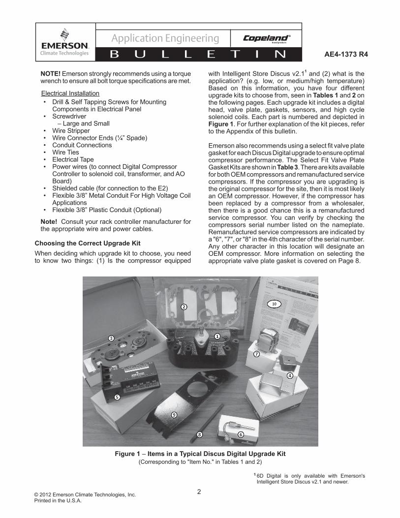
with Intelligent Store Discus v2.11 and (2) what is the application? (e.g. low, or medium/high temperature) Based on this information, you have four different upgrade kits to choose from, seen in Tables 1 and 2 on the following pages. Each upgrade kit includes a digital head, valve plate, gaskets, sensors, and high cycle solenoid coils. Each part is numbered and depicted in Figure 1. For further explanation of the kit pieces, refer to the Appendix of this bulletin.
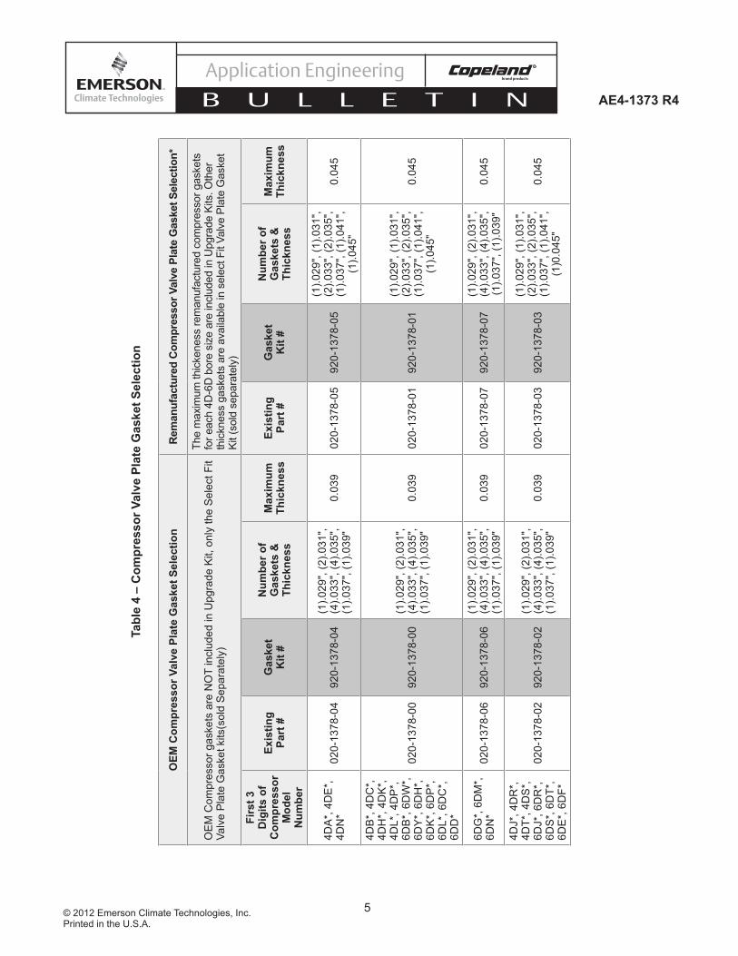
Emerson also recommends using a select fi t valve plate gasket for each Discus Digital upgrade to ensure optimal compressor performance. The Select Fit Valve Plate Gasket Kits are shown in Table 3. There are kits available for both OEM compressors and remanufactured service compressors. If the compressor you are upgrading is the original compressor for the site, then it is most likely an OEM compressor. However, if the compressor has been replaced by a compressor from a wholesaler, then there is a good chance this is a remanufactured service compressor. You can verify by checking the compressors serial number listed on the nameplate. Remanufactured service compressors are indicated by a "6", "7", or "8" in the 4th character of the serial number. Any other character in this location will designate an OEM compressor. More information on selecting the appropriate valve plate gasket is covered on Page 8.
Figure 1 – Items in a Typical Discus Digital Upgrade Kit (Corresponding to "Item No." in Tables 1 and 2)
1 6D Digital is only available with Emerson's Intelligent Store Discus v2.1 and newer.

3© 2012 Emerson Climate Technologies, Inc.Printed in the U.S.A.
AE4-1373 R4
Application Engineering
B U L L E T I N
Table 1 – 4D Discus Digital Upgrade Kits
Kit Kit P/N Item No. Item Description Item P/N
Medium Temperature
4D Discus Digital
Upgrade Kit (Non-ISD)
980-6000-00
1 & 2Head Service Kit - Digital Head Assembly - Gaskets
902-0323-00
34D Discus Digital Valve Plate Kit (MT) - Digital Valve Plate - Gaskets
998-2661-66
4Solenoid Coil Kit x2 (120V & 220V) - Solenoid Bracket - Screw
923-0084-01, -02
5 4D IDCM Module Kit / Copeland Digital Compressor Controller 943-0088-00
6 Sensor Temp Probe Kit 985-0109-07
7 24V Transformer (Class 2) 037-0023-00
8 Head Stud 103-0087-07
10Instructional Sheets - AE8-1328 Copeland Digital Discus Compressor Controller - AE4-1373 Upgrade Procedures for Copeland Digital Discus
N/A
Low Temperature
4D Discus Digital
Upgrade Kit (Non-ISD)
980-6000-01
1 & 2Head Service Kit - Digital Head Assembly - Gaskets
902-0323-00
34D Discus Digital Valve Plate Kit (LT) - Digital Valve Plate - Gaskets
998-2661-65
4Solenoid Coil Kit x2 (120V & 220V) - Solenoid Bracket - Screw
923-0084-01, -02
5 4D IDCM Module Kit / Copeland Digital Compressor Controller 943-0088-00
6 Sensor Temp Probe Kit 985-0109-07
7 24V Transformer (Class 2) 037-0023-00
8 Head Stud 103-0087-07
9 Fan Bracket 074-1243-00
10Instructional Sheets
- AE8-1328 Copeland Digital Discus Compressor Controller - AE4-1373 Upgrade Procedures for Copeland Digital Discus
N/A

4© 2012 Emerson Climate Technologies, Inc.Printed in the U.S.A.
AE4-1373 R4
Application Engineering
B U L L E T I N
Table 2 – 4D/6D Intelligent Store Discus v2.x Digital Upgrade Kits
Kit Kit P/N Item No. Item Description Item P/N
Medium Temperature
4D/6D Intelligent
Store Discus v2.x Digital Upgrade Kit
980-6000-10
1 & 2Head Service Kit - Digital Head Assembly - Gaskets
902-0323-00
34D/6D Discus Digital Valve Plate Kit (MT) - Digital Valve Plate - Gaskets
998-2661-66
4 Solenoid Coil (24VAC) 923-0084-00
8 Head Stud 103-0087-07
10 Instructional Sheets - AE4-1373 Upgrade Procedures for Copeland Digital Discus N/A
Low Temperature
4D/6D Intelligent
Store Discus v2.x Digital Upgrade Kit
980-6000-11
1 & 2Head Service Kit - Digital Head Assembly - Gaskets
902-0323-00
34D/6D Discus Digital Valve Plate Kit (LT) - Digital Valve Plate - Gaskets
998-2661-65
4 Solenoid Coil (24VAC) 923-0084-00
8 Head Stud 103-0087-07
9 Fan Bracket 074-1243-00
10 Instructional Sheets - AE4-1373 Upgrade Procedures for Copeland Digital Discus N/A
Table 3 – Valve Plate Gasket Kit Part Numbers
Kit Description Kit Part #
OEM Compressor Remanufactured/ Service Compressor
4DA*,4DE*,4DN* Select Fit Valve Plate Gasket Kit 920-1378-04 920-1378-05
4DB*,4DC*,4DH*,4DK*,4DL*,4DP*,6DB*,6DW*,6DY*,6DH*,6DK*,6DP*,6DL*,6DC*,6DD* Select Fit Valve Plate Gasket Kit 920-1378-00 920-1378-01
6DG*,6DM*,6DN* 920-1378-06 920-1378-07
4DJ*,4DR*,4DT*,4DS*,6DJ*,6DR*, 6DS*,6DT*,6DE*,6DF* Select Fit Valve Plate Gasket Kit 920-1378-02 920-1378-03
There are four valve plate gaskets provided in both the head-service kit and the valve plate kit. The appropriate gasket should be matched to the fi rst three digits of the compressor model number.
Remanufactured compressors are designated by a "6", "7", or "8" in the 4th character in the serial number (e.g.06B6xxxxx).Any other character in this location will designate an OEM compressor. (e.g. 03C0xxxxx)
5© 2012 Emerson Climate Technologies, Inc.Printed in the U.S.A.
AE4-1373 R4
Application Engineering
B U L L E T I N
OEM
Com
pres
sor V
alve
Pla
te G
aske
t Sel
ectio
nR
eman
ufac
ture
d C
ompr
esso
r Val
ve P
late
Gas
ket S
elec
tion*
OE
M C
ompr
esso
r gas
kets
are
NO
T in
clud
ed in
Upg
rade
Kit,
onl
y th
e S
elec
t Fit
Valv
e P
late
Gas
ket k
its(s
old
Sep
arat
ely)
The
max
imum
thic
kene
ss re
man
ufac
ture
d co
mpr
esso
r gas
kets
fo
r eac
h 4D
-6D
bor
e si
ze a
re in
clud
ed in
Upg
rade
Kits
. Oth
er
thic
knes
s ga
sket
s ar
e av
aila
ble
in s
elec
t Fit
Valv
e Pl
ate
Gas
ket
Kit (
sold
sep
arat
ely)
Firs
t 3
Dig
its o
f C
ompr
esso
r M
odel
N
umbe
r
Exis
ting
Part
#G
aske
t K
it #
Num
ber o
f G
aske
ts &
Th
ickn
ess
Max
imum
Th
ickn
ess
Exis
ting
Part
#G
aske
t K
it #
Num
ber o
f G
aske
ts &
Th
ickn
ess
Max
imum
Th
ickn
ess
4DA
*, 4
DE
*,
4DN
*02
0-13
78-0
492
0-13
78-0
4(1
).029
", (2
).031
",(4
).033
", (4
).035
", (1
).037
", (1
).039
"0.
039
020-
1378
-05
920-
1378
-05
(1).0
29",
(1).0
31",
(2).0
33",
(2).0
35",
(1).0
37",
(1).0
41",
(1).0
45"
0.04
5
4DB
*, 4
DC
*,
4DH
*, 4
DK
*,
4DL*
, 4D
P*,
6D
B*,
6D
W*,
6D
Y*,
6D
H*,
6D
K*,
6D
P*,
6D
L*, 6
DC
*,
6DD
*
020-
1378
-00
920-
1378
-00
(1).0
29",
(2).0
31",
(4).0
33",
(4).0
35",
(1).0
37",
(1).0
39"
0.03
902
0-13
78-0
192
0-13
78-0
1
(1).0
29",
(1).0
31",
(2).0
33",
(2).0
35",
(1).0
37",
(1).0
41",
(1).0
45"
0.04
5
6DG
*, 6
DM
*,
6DN
*02
0-13
78-0
692
0-13
78-0
6(1
).029
", (2
).031
", (4
).033
", (4
).035
", (1
).037
", (1
).039
"0.
039
020-
1378
-07
920-
1378
-07
(1).0
29",
(2).0
31",
(4).0
33",
(4).0
35",
(1).0
37",
(1).0
39"
0.04
5
4DJ*
, 4D
R*,
4D
T*, 4
DS
*,
6DJ*
, 6D
R*,
6D
S*,
6D
T*,
6DE
*, 6
DF*
020-
1378
-02
920-
1378
-02
(1).0
29",
(2).0
31",
(4).0
33",
(4).0
35",
(1).0
37",
(1).0
39"
0.03
902
0-13
78-0
392
0-13
78-0
3
(1).0
29",
(1).0
31",
(2).0
33",
(2).0
35",
(1).0
37",
(1).0
41",
(1)0
.045
"
0.04
5
Tabl
e 4
– C
ompr
esso
r Val
ve P
late
Gas
ket S
elec
tion
6© 2012 Emerson Climate Technologies, Inc.Printed in the U.S.A.
AE4-1373 R4
Application Engineering
B U L L E T I N
Copeland Discus/Intelligent Store Discus v2.1 to Copeland Discus Digital Head and Valve Plate ConversionNote! Please review this section even if you are familiar with a standard Discus head and valve plate conversion. Refer to Checklist #1 for the compressor head and valve plate change, which can be found in the Appendix at the end of this document.
Note! The 4D/6D Digital head must be installed on the far right hand bank (when facing the oil pump end) of compressor
1. Prepare compressor for a head change, per industry standards:
• Front seat suction service valve• Pumpdown compressor• Disconnect power to compressor• Front seat discharge service valve and oil
supply valve (If applicable)• Depressurize compressor
2. Remove any high pressure connections from the head and the head fan (if equipped).
3. Note the location of any studs on the head (high pressure control and oil pressure module may be mounted here).
4. Remove the cylinder head bolts.
5. Tap the head to break it loose from the valve plate.
6. Remove dowel pins and center bolt. Save dowel pins for digital head and valve plate installation. Center bolt will NOT be needed for digital head and valve plate installation.
7. Lightly tap up on the tab or on the side of the valve plate to loosen and then remove valve plate. Use caution to not damage the compressor deck surface.
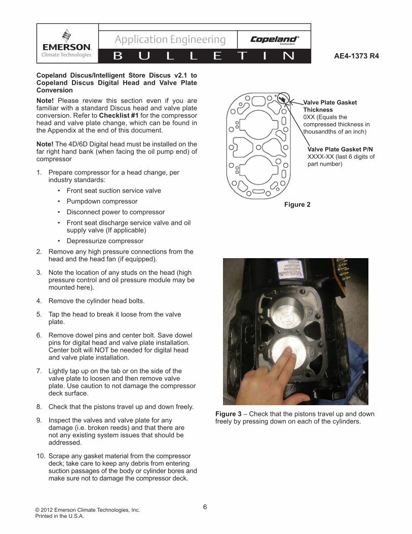
8. Check that the pistons travel up and down freely.
9. Inspect the valves and valve plate for any damage (i.e. broken reeds) and that there are not any existing system issues that should be addressed.
10. Scrape any gasket material from the compressor deck; take care to keep any debris from entering suction passages of the body or cylinder bores and make sure not to damage the compressor deck.
Valve Plate Gasket P/NXXXX-XX (last 6 digits of
part number)
Valve Plate Gasket Thickness0XX (Equals the
compressed thickness in
thousandths of an inch)
Figure 2
Figure 3 – Check that the pistons travel up and down freely by pressing down on each of the cylinders.
7© 2012 Emerson Climate Technologies, Inc.Printed in the U.S.A.
AE4-1373 R4
Application Engineering
B U L L E T I N
11. Select the proper valve plate gasket for the bore size of the compressor. (See Table 3)
12. Lightly coat both sides of the new valve plate gasket with assembly oil. Orient the valve plate gasket with dowel pins and ports. Install valve plate gasket. TAB SHOULD BE ORIENTED ON THE OIL PUMP END WITH PART NUMBER ON TOP.
13. Inspect new valve plate for handling damage and install.
14. Lightly oil both sides of the Discus digital head gasket and install. TAB SHOULD BE ORIENTED ON THE OIL PUMP END WITH PART NUMBER ON TOP.
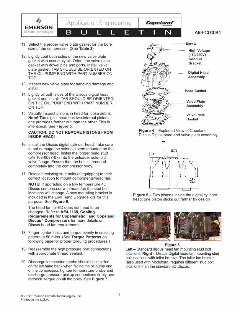
15. Visually inspect pistons in head for loose debris. Note! The digital head has two internal pistons, one protrudes farther out than the other. This is intentional. See Figure 5.CAUTION: DO NOT REMOVE PISTONS FROM INSIDE HEAD!
16. Install the Discus digital cylinder head. Take care to not damage the solenoid stem mounted on the compressor head. Install the longer head stud (p/n 103-0087-07) into the unloader solenoid valve fl ange. Ensure that the bolt is threaded completely into the compressor body.
17. Relocate existing stud bolts (if equipped) to their correct location to mount components/head fan.NOTE! If upgrading on a low temperature 4D Discus compressor with head fan the stud bolt locations will change. A new mounting bracket is included in the Low Temp Upgrade kits for this purpose. See Figure 6.The head fan for 6D does not need to be changed. Refer to AE4-1135, Cooling Requirements for Copelametic™ and Copeland Discus™ Compressors for more details on Discus head fan requirements.
18. Finger tighten bolts and torque evenly in crossing pattern to 50 ft-lbs. (See Torque Patterns on following page for proper torquing procedures.)
19. Reassemble the high pressure port connections with appropriate thread sealant.
20. Discharge temperature probe should be installed on far left hand bank when facing the oil pump end of the compressor.Tighten temperature probe and discharge pressure pickup connections fi rmly and recheck torque on all the bolts. See Figure 7.
Figure 5 – Two pistons inside the digital cylinder head, one piston sticks out farther by design
Figure 4 – Exploded View of Copeland Discus Digital head and valve plate assembly
Screw
Digital Head Assembly
Head Gasket
Valve Plate Assembly
Valve Plate Gasket
High Voltage (110/220V) Conduit Bracket
Figure 6 Left – Standard discus head fan mounting stud bolt locations; Right – Discus Digital head fan mounting stud bolt locations with taller bracket. The taller fan bracket (also used with Moduload) requires different stud bolt locations than the standard 3D Discus.

8© 2012 Emerson Climate Technologies, Inc.Printed in the U.S.A.
AE4-1373 R4
Application Engineering
B U L L E T I N
1 Intelligent Store Discus compressors with Demand Cooling are pending approval.2 Required for non-Intelligent Store Discus only.3 Refer to installation instructions supplied with fan mounting kit.
21. Refer to Checklist #1 in Appendix to verify all steps have been completed in the head and valve plate conversion.
22. Evacuate compressor and reopen all the necessary valves to the compressor per industry standards.
23. Leak test the compressor.
24. Install Discus Digital™ solenoid coil, solenoid bracket2, and conduit2 on solenoid valve stem2. Make sure to choose correct voltage solenoid coil. See Figure 8.
25. If the compressor is equipped with a head fan, install3 fan bracket and head fan3.
Torque Patterns For all cover plates (heads, bottom plates, shipping pads, valves, etc.) to achieve a proper seal, it is important when applying torque to use a criss-cross pattern. Follow the steps below.
Do not apply torque in a circular pattern. For the initial torque, apply no more than 70% of the fi nal torque using a diagonal criss-cross pattern, similar to the example in Figure 9. Once the initial torque has been applied, apply the proper full torque value, again using a criss-cross pattern. Once the fi nal torque has been applied, start at any bolt, and circle the entire part in sequence. This will verify that a bolt has not been missed and that fi nal torque has been applied.
Figure 9
Screw
High Voltage (110/220V) Conduit Bracket
Figure 8 – Solenoid coil assembly including bracket
Longer head stud
Figure 7 – The temperature probe should be installed on the far left bank of the 4D/6D.
TemperatureProbe on 6D
Discus Digital Bank
Blocked Suction (Optional) Bank
TemperatureProbe on 4D
Discus Digital Bank
9© 2012 Emerson Climate Technologies, Inc.Printed in the U.S.A.
AE4-1373 R4
Application Engineering
B U L L E T I N
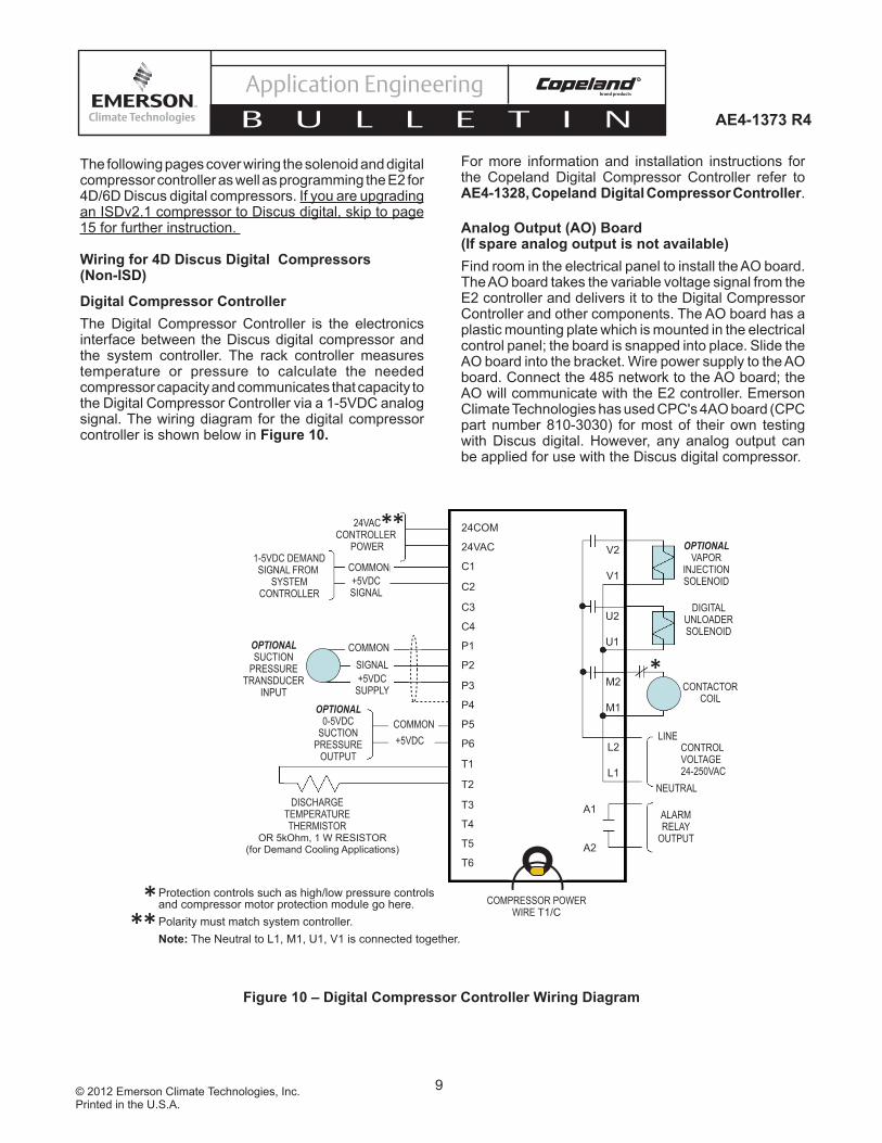
Figure 10 – Digital Compressor Controller Wiring Diagram
24VACCONTROLLER
POWER
COMMON+5VDCSIGNAL
1-5VDC DEMANDSIGNAL FROM
SYSTEMCONTROLLER
OPTIONALSUCTION
PRESSURETRANSDUCER
INPUT
COMMON
+5VDCSUPPLY
SIGNAL
OPTIONAL0-5VDC
SUCTIONPRESSURE
OUTPUT
COMMON+5VDC
DISCHARGETEMPERATURETHERMISTOR
OPTIONALVAPOR
INJECTIONSOLENOID
DIGITALUNLOADERSOLENOID
CONTACTORCOIL
LINE
NEUTRAL
CONTROLVOLTAGE24-250VAC
ALARMRELAY
OUTPUT
COMPRESSOR POWERWIRE T1/C
24COM
24VAC
C1
C2
C3
C4
P1
P2
P3
P4
P5
P6
T1
T2
T3
T4
T5
T6
V2
V1
U2
U1
M2
M1
L2
L1
A1
A2
**
*
OR 5kOhm, 1 W RESISTOR (for Demand Cooling Applications)
Protection controls such as high/low pressure controls and compressor motor protection module go here.Polarity must match system controller.Note: The Neutral to L1, M1, U1, V1 is connected together.
***
For more information and installation instructions for the Copeland Digital Compressor Controller refer to AE4-1328, Copeland Digital Compressor Controller.
Analog Output (AO) Board (If spare analog output is not available)Find room in the electrical panel to install the AO board.The AO board takes the variable voltage signal from the E2 controller and delivers it to the Digital Compressor Controller and other components. The AO board has a plastic mounting plate which is mounted in the electrical control panel; the board is snapped into place. Slide the AO board into the bracket. Wire power supply to the AO board. Connect the 485 network to the AO board; the AO will communicate with the E2 controller. Emerson Climate Technologies has used CPC's 4AO board (CPC part number 810-3030) for most of their own testing with Discus digital. However, any analog output can be applied for use with the Discus digital compressor.
The following pages cover wiring the solenoid and digital compressor controller as well as programming the E2 for 4D/6D Discus digital compressors. If you are upgrading an ISDv2.1 compressor to Discus digital, skip to page 15 for further instruction.
Wiring for 4D Discus Digital Compressors (Non-ISD)
Digital Compressor ControllerThe Digital Compressor Controller is the electronics interface between the Discus digital compressor and the system controller. The rack controller measures temperature or pressure to calculate the needed compressor capacity and communicates that capacity to the Digital Compressor Controller via a 1-5VDC analog signal. The wiring diagram for the digital compressor controller is shown below in Figure 10.

10© 2012 Emerson Climate Technologies, Inc.Printed in the U.S.A.
AE4-1373 R4
Application Engineering
B U L L E T I N
Programming The E2 For Non-ISD Copeland Discus Digital
When using the digital compressor controller you need an E2 v2.3 or newer. An analog output point is needed on the controller. You may need to install an AO board if there is not an available point in the E2.
Note! The digital compressor should be set as one stage in the E2. If upgrading from Copeland blocked suction, you will need to delete the extra unloader stage set up accordingly in the suction group.
Note! These instructions are based on E2 v2.6
These are suggested E2 instructions based on Emerson’s experience. There may be more than one
way to properly program the E2 for Discus digital. Use Checklist #3 in the Appendix to verify the digital is being controlled properly.
In order to program the E2 for Copeland Discus Digital using the digital compressor controller you will perform the following steps:
1. Override compressor OFF2. Setup suction group and assign an output to the
Digital Compressor Controller3. Setup analog output4. Disable compressor override
Below you will see screen shots taken from the E2 to perform the above steps.
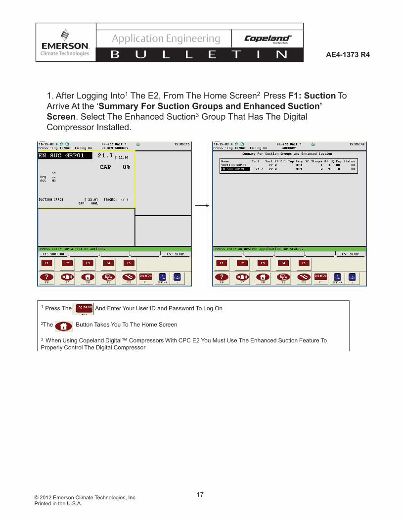
1. After Logging Into1 The E2, From The Home Screen2 Press F1: Suction To
Arrive At the ‘Summary For Suction Groups and Enhanced Suction’ Screen. Select The Enhanced Suction3 Group That Has The Digital
Compressor Installed.
1 Press The And Enter Your User ID and Password To Log On
2The Button Takes You To The Home Screen
3 When Using Copeland Digital™ Compressors With CPC E2 You Must Use The Enhanced Suction Feature To
Properly Control The Digital Compressor
11© 2012 Emerson Climate Technologies, Inc.Printed in the U.S.A.
AE4-1373 R4
Application Engineering
B U L L E T I N
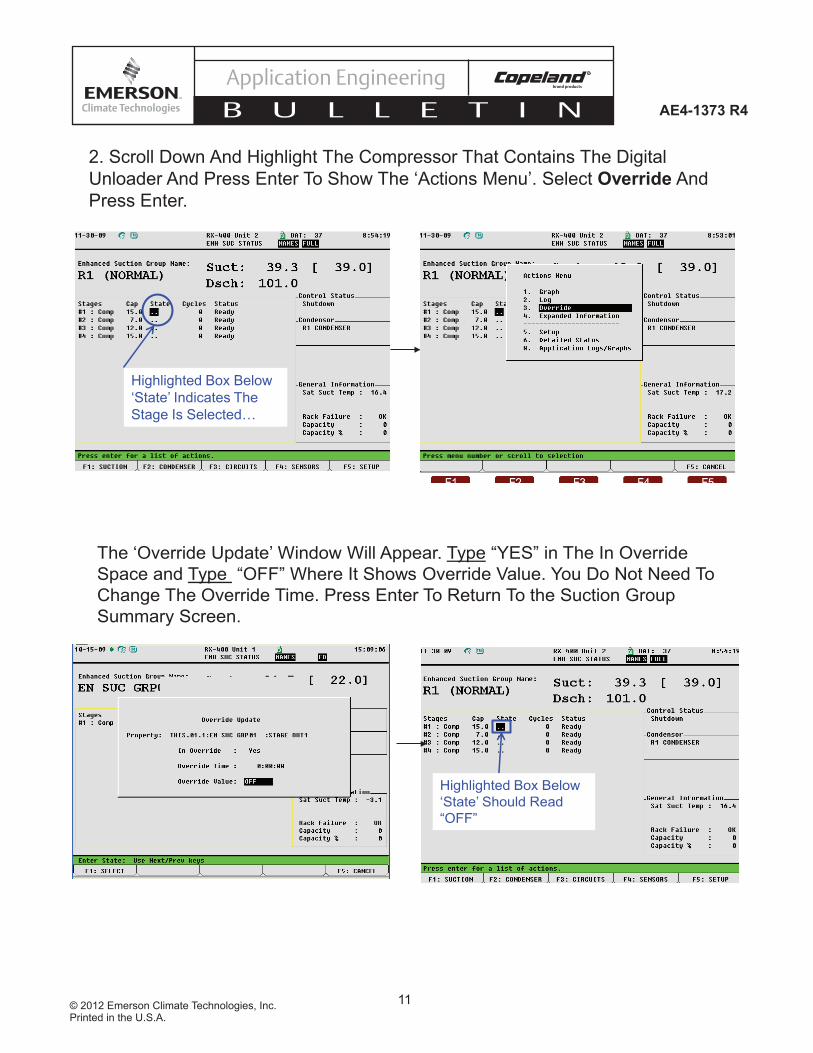
2. Scroll Down And Highlight The Compressor That Contains The Digital
Unloader And Press Enter To Show The ‘Actions Menu’. Select Override And
Press Enter.
Highlighted Box Below
‘State’ Indicates The
Stage Is Selected…
The ‘Override Update’ Window Will Appear. Type “YES” in The In Override
Space and Type “OFF” Where It Shows Override Value. You Do Not Need To
Change The Override Time. Press Enter To Return To the Suction Group
Summary Screen.
Highlighted Box Below
‘State’ Should Read
“OFF”
12© 2012 Emerson Climate Technologies, Inc.Printed in the U.S.A.
AE4-1373 R4
Application Engineering
B U L L E T I N
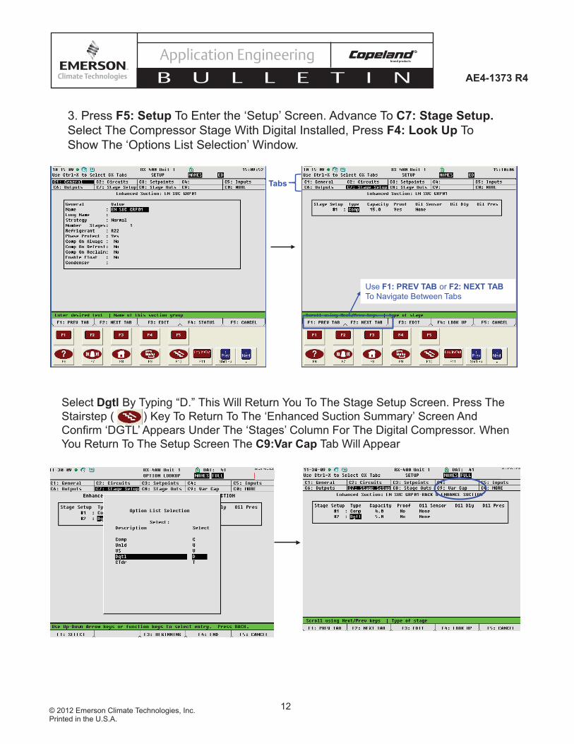
3. Press F5: Setup To Enter the ‘Setup’ Screen. Advance To C7: Stage Setup. Select The Compressor Stage With Digital Installed, Press F4: Look Up To
Show The ‘Options List Selection’ Window.
Use F1: PREV TAB or F2: NEXT TAB To Navigate Between Tabs
Tabs
Select Dgtl By Typing “D.” This Will Return You To The Stage Setup Screen. Press The
Stairstep ( ) Key To Return To The ‘Enhanced Suction Summary’ Screen And
Confirm ‘DGTL’ Appears Under The ‘Stages’ Column For The Digital Compressor. When
You Return To The Setup Screen The C9:Var Cap Tab Will Appear
13© 2012 Emerson Climate Technologies, Inc.Printed in the U.S.A.
AE4-1373 R4
Application Engineering
B U L L E T I N
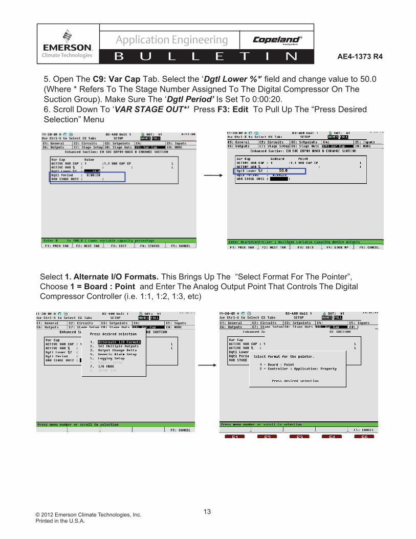
5. Open The C9: Var Cap Tab. Select the ‘Dgtl Lower %*’ field and change value to 50.0
(Where * Refers To The Stage Number Assigned To The Digital Compressor On The
Suction Group). Make Sure The ‘Dgtl Period’ Is Set To 0:00:20.
6. Scroll Down To ‘VAR STAGE OUT*’ Press F3: Edit To Pull Up The “Press Desired
Selection” Menu
Select 1. Alternate I/O Formats. This Brings Up The “Select Format For The Pointer”,
Choose 1 = Board : Point and Enter The Analog Output Point That Controls The Digital
Compressor Controller (i.e. 1:1, 1:2, 1:3, etc)

14© 2012 Emerson Climate Technologies, Inc.Printed in the U.S.A.
AE4-1373 R4
Application Engineering
B U L L E T I N
7. Return To The Home Screen (Press ). Go To The Main Menu (Press ).
Select 7. System Configuration. Select 2. Output Definitions.
8. Scroll Down To Select The Analog Output Point Connected To The Digital Compressor
Controller. Press Enter and Select 5. Setup From The Actions Menu. Modify The ‘Low End Point’ and ‘High End Point’ To 1.0 And 5.0 Respectively.

15© 2012 Emerson Climate Technologies, Inc.Printed in the U.S.A.
AE4-1373 R4
Application Engineering
B U L L E T I N
9. Return To The Suction Group Page And Remove The Compressor Override (Type “No”
After ‘In Override’ )

16© 2012 Emerson Climate Technologies, Inc.Printed in the U.S.A.
AE4-1373 R4
Application Engineering
B U L L E T I N
Wiring for Intelligent Store Discus v2.1 or NewerIf installing Discus digital on an Intelligent Store Discus v2.1 compressor the only wiring needed after head and valve plate change is connecting the unloader wire connections found in the Intelligent Store Discus wiring harness. To connect, remove the ISD side cover and connect the unloader wires (yellow) found in the wiring harness to the solenoid coil.
NOTE! Always connect Unl 1 (yellow wires) to digital bank solenoid. If using on a 6D with blocked suction bank on middle bank connect Unl 2 (purple wires) to blocked suction solenoid.
Replace the ISD side cover. See Figure 11.
Programming The E2 for Intelligent Store Discus Digital
When using with ISD v2.x, E2 v2.6 or newer must be used. Update E2 fi rmware if necessary. An analog output point is not needed on the controller. Communication is done through the RS485 communication cable.
Note! The digital compressor should be set as one stage in the E2. If upgrading from Copeland blocked suction, you will need to delete the extra unloader stage(s) set up accordingly in the suction group.
Note! These instructions are based on E2 v2.8
Figure 11 Intelligent Store Discus v2.1 Wiring
These are suggested E2 instructions based on Emerson’s experience. There may be more than one way to properly program the E2 for Intelligent Store Discus Digital. Use Checklist #3 to verify the digital is being controlled properly.
In order to program the E2 for Copeland Discus Digital using the digital compressor controller you will perform the following steps:
1. Establish the E2 control and communication SEND link
a. Override compressor OFFb. Identify the compressor stage as a
digital compressor3. Establish the ISDv2.x communication
RECEIVE linka. Setup unloader control in ISDv2.x and
defi ne unloader control type as digital b. Defi ne digital controller, application and
property inputsc. Disable compressor override
On the following pages you will see screen shots taken from the E2 to perform the above steps.
17© 2012 Emerson Climate Technologies, Inc.Printed in the U.S.A.
AE4-1373 R4
Application Engineering
B U L L E T I N
1. After Logging Into1 The E2, From The Home Screen2 Press F1: Suction To
Arrive At the ‘Summary For Suction Groups and Enhanced Suction’ Screen. Select The Enhanced Suction3 Group That Has The Digital
Compressor Installed.
1 Press The And Enter Your User ID and Password To Log On
2The Button Takes You To The Home Screen
3 When Using Copeland Digital™ Compressors With CPC E2 You Must Use The Enhanced Suction Feature To
Properly Control The Digital Compressor
18© 2012 Emerson Climate Technologies, Inc.Printed in the U.S.A.
AE4-1373 R4
Application Engineering
B U L L E T I N
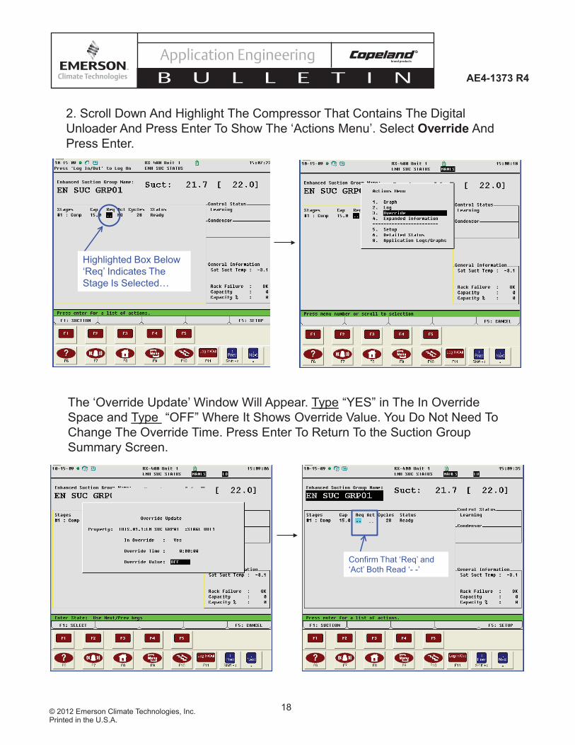
The ‘Override Update’ Window Will Appear. Type “YES” in The In Override
Space and Type “OFF” Where It Shows Override Value. You Do Not Need To
Change The Override Time. Press Enter To Return To the Suction Group
Summary Screen.
Confirm That ‘Req’ and
‘Act’ Both Read ‘- -’
2. Scroll Down And Highlight The Compressor That Contains The Digital
Unloader And Press Enter To Show The ‘Actions Menu’. Select Override And
Press Enter.
Highlighted Box Below
‘Req’ Indicates The
Stage Is Selected…
19© 2012 Emerson Climate Technologies, Inc.Printed in the U.S.A.
AE4-1373 R4
Application Engineering
B U L L E T I N
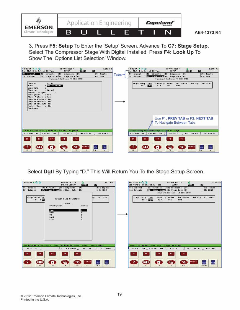
3. Press F5: Setup To Enter the ‘Setup’ Screen. Advance To C7: Stage Setup. Select The Compressor Stage With Digital Installed, Press F4: Look Up To
Show The ‘Options List Selection’ Window.
Use F1: PREV TAB or F2: NEXT TAB To Navigate Between Tabs
Tabs
Select Dgtl By Typing “D.” This Will Return You To the Stage Setup Screen.

20© 2012 Emerson Climate Technologies, Inc.Printed in the U.S.A.
AE4-1373 R4
Application Engineering
B U L L E T I N
5. Press The Menu Button ( ) To Bring Up The ‘Main Menu.’ Select
Configured Applications. This Produces The ‘Configured Applications’
Window, Select ISD 2.0
4. Press The Home Key To Return To The Home Screen. A Window Will Pop
Up Notifying That Changes Were Made To The Application Type “Y” To Confirm
You Would Like To Continue. The Home Screen Should Show DGTL 0%
---Communication SEND Link Is Now Established----
21© 2012 Emerson Climate Technologies, Inc.Printed in the U.S.A.
AE4-1373 R4
Application Engineering
B U L L E T I N
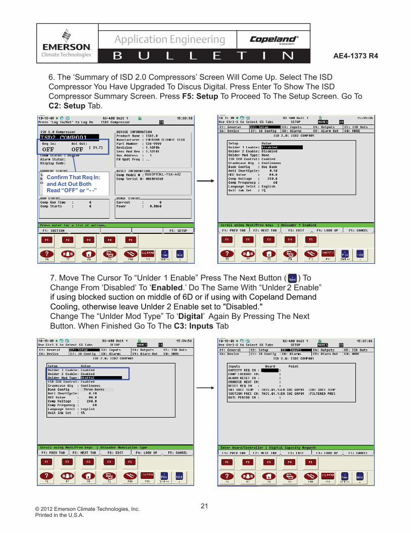
6. The ‘Summary of ISD 2.0 Compressors’ Screen Will Come Up. Select The ISD
Compressor You Have Upgraded To Discus Digital. Press Enter To Show The ISD
Compressor Summary Screen. Press F5: Setup To Proceed To The Setup Screen. Go To
C2: Setup Tab.
Confirm That Req In: and Act Out Both Read “OFF” or “- -”
6DD3F93KL-TSK-A42
7. Move The Cursor To “Unlder 1 Enable” Press The Next Button ( ) To
Change From ‘Disabled’ To ‘Enabled.’ Do The Same With “Unlder 2 Enable”
Change The “Unlder Mod Type” To ‘Digital’ Again By Pressing The Next
Button. When Finished Go To The C3: Inputs Tab
if using blocked suction on middle of 6D or if using with Copeland Demand
Cooling, otherwise leave Unlder 2 Enable set to "Disabled."
Three Banks

22© 2012 Emerson Climate Technologies, Inc.Printed in the U.S.A.
AE4-1373 R4
Application Engineering
B U L L E T I N
9. Type “2” To Select The Controller : Application : Property Format For The
Pointer. With The Cursor In The Controller Field Of “Capcity Req In” Press F4: Look Up. Select the Controller From The ‘Controller Selection’ Window.
8. Move The Cursor To “Capcity Req In”. Press F3: Edit. In The New Window,
Select Alternate I/O Formats

23© 2012 Emerson Climate Technologies, Inc.Printed in the U.S.A.
AE4-1373 R4
Application Engineering
B U L L E T I N
Move the Cursor To The Application Space. Press F4: Look Up And Select The Suction
Group Application The Digital Is On. Next Move The Cursor To The Output Space And
Type “VAR STAGE OUTX” Where X Represents The Stage Number Of The Digital
Compressor.
10. Move The Cursor Down To “Dgtl Period In” Follow The Same Steps As
Before To Edit The Format Of The Input (Use F3: Edit and F4: Look UpFeatures). In The Output Space Type “DGTL PERIOD”.
Controller And Application Should
Remain The Same For All Inputs.
24© 2012 Emerson Climate Technologies, Inc.Printed in the U.S.A.
AE4-1373 R4
Application Engineering
B U L L E T I N
For more detailed information on programming the E2, refer to the E2 User manual found at http://www.emersonclimate.com/Documents/026-1610.pdf
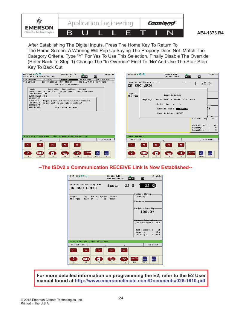
--The ISDv2.x Communication RECEIVE Link Is Now Established--
After Establishing The Digital Inputs, Press The Home Key To Return To
The Home Screen. A Warning Will Pop Up Saying The Property Does Not Match The
Category Criteria. Type “Y” For Yes To Use This Selection. Finally Disable The Override
(Refer Back To Step 1) Change The “In Override” Field To ‘No’ And Use The Stair Step
Key To Back Out

25© 2012 Emerson Climate Technologies, Inc.Printed in the U.S.A.
AE4-1373 R4
Application Engineering
B U L L E T I N
The contents of this publication are presented for informational purposes only and are not to be construed as warranties or guarantees, express or implied, regarding the products or services described herein or their use or applicability. Emerson Climate Technologies, Inc. and/or its affi liates (collectively "Emerson"), as applicable, reserve the right to modify the design or specifi cations of such products at any time without notice. Emerson does not assume responsibility for the selection, use or maintenance of any product. Responsibility for proper selection, use and maintenance of any Emerson product remains solely with the purchaser or end user.
Warranty InformationEmerson Climate Technologies, Inc. warrants its Digital Compressor Controller to be free from defects in materials and workmanship under normal use for a period of one year from the date of purchase or twenty months from manufacture whichever comes fi rst. During this period, Emerson Climate Technologies, Inc. will replace any defective module without charge.
This warranty is valid for the original purchaser from the date of initial purchase and is not transferable. Keep the original sales receipt. Proof of purchase is required to obtain warranty replacement. Dealers or service centers selling this product do not have the right to alter, modify or in any way change the terms and conditions of this warranty.
This warranty does not cover normal wear of parts or damage resulting from any of the following: negligent use or misuse of the product, use on improper voltage or current, use contrary to the operating instructions, disassembly, repair or alteration by anyone other than Emerson Climate Technologies, Inc.. Further, the warranty does not cover acts of God, such as fi re, fl ood, hurricanes and tornadoes.
EMERSON CLIMATE TECHNOLOGIES, INC. MAKES NO IMPLIED WARRANTIES OF MERCHANTABILITY OR FITNESS FOR PARTICULAR PURPOSE WITH RESPECT TO THE Copeland Digital Compressor Controller.
Emerson Climate Technologies, Inc. shall not be liable for any incidental or consequential damages caused by the breach of any express or implied warranty. Some states, provinces, or jurisdictions do not allow the exclusion or limitation of incidental or consequential damages or limitations on how long an implied warranty lasts, so the above limitations or exclusions may not apply to you. This warranty gives you specifi c legal rights, and you may also have other rights that vary from state to state, or province to province.
Units under warranty and in need of repair should be returned to an authorized wholesaler or original equipment manufacturer.
SupportFor more information visit www.EmersonClimate.com or contact Emerson Climate Technologies, Inc. at 1-888-EMR-9950.
26© 2012 Emerson Climate Technologies, Inc.Printed in the U.S.A.
AE4-1373 R4
Application Engineering
B U L L E T I N
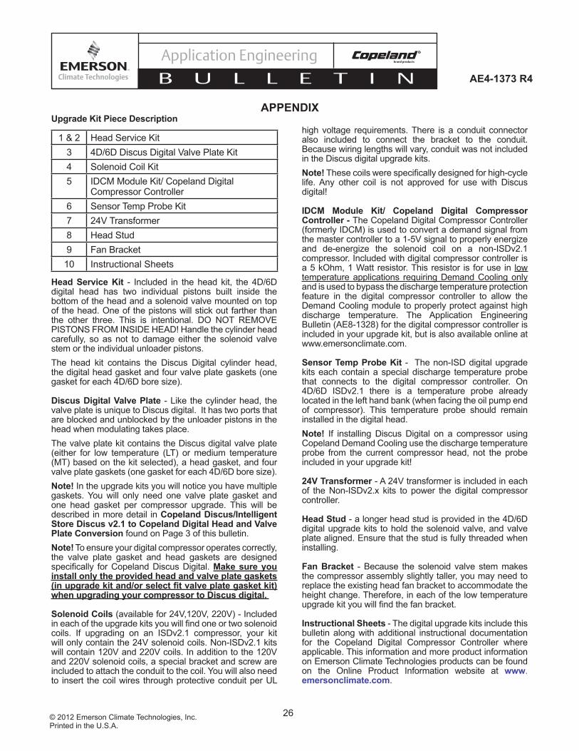
Upgrade Kit Piece Description
1 & 2 Head Service Kit3 4D/6D Discus Digital Valve Plate Kit4 Solenoid Coil Kit5 IDCM Module Kit/ Copeland Digital
Compressor Controller 6 Sensor Temp Probe Kit7 24V Transformer8 Head Stud9 Fan Bracket10 Instructional Sheets
Head Service Kit - Included in the head kit, the 4D/6D digital head has two individual pistons built inside the bottom of the head and a solenoid valve mounted on top of the head. One of the pistons will stick out farther than the other three. This is intentional. DO NOT REMOVE PISTONS FROM INSIDE HEAD! Handle the cylinder head carefully, so as not to damage either the solenoid valve stem or the individual unloader pistons. The head kit contains the Discus Digital cylinder head, the digital head gasket and four valve plate gaskets (one gasket for each 4D/6D bore size).
Discus Digital Valve Plate - Like the cylinder head, the valve plate is unique to Discus digital. It has two ports that are blocked and unblocked by the unloader pistons in the head when modulating takes place.The valve plate kit contains the Discus digital valve plate (either for low temperature (LT) or medium temperature (MT) based on the kit selected), a head gasket, and four valve plate gaskets (one gasket for each 4D/6D bore size). Note! In the upgrade kits you will notice you have multiple gaskets. You will only need one valve plate gasket and one head gasket per compressor upgrade. This will be described in more detail in Copeland Discus/Intelligent Store Discus v2.1 to Copeland Digital Head and Valve Plate Conversion found on Page 3 of this bulletin.Note! To ensure your digital compressor operates correctly, the valve plate gasket and head gaskets are designed specifi cally for Copeland Discus Digital. Make sure you install only the provided head and valve plate gaskets (in upgrade kit and/or select fi t valve plate gasket kit) when upgrading your compressor to Discus digital.
Solenoid Coils (available for 24V,120V, 220V) - Included in each of the upgrade kits you will fi nd one or two solenoid coils. If upgrading on an ISDv2.1 compressor, your kit will only contain the 24V solenoid coils. Non-ISDv2.1 kits will contain 120V and 220V coils. In addition to the 120V and 220V solenoid coils, a special bracket and screw are included to attach the conduit to the coil. You will also need to insert the coil wires through protective conduit per UL
high voltage requirements. There is a conduit connector also included to connect the bracket to the conduit. Because wiring lengths will vary, conduit was not included in the Discus digital upgrade kits. Note! These coils were specifi cally designed for high-cycle life. Any other coil is not approved for use with Discus digital!
IDCM Module Kit/ Copeland Digital Compressor Controller - The Copeland Digital Compressor Controller (formerly IDCM) is used to convert a demand signal from the master controller to a 1-5V signal to properly energize and de-energize the solenoid coil on a non-ISDv2.1 compressor. Included with digital compressor controller is a 5 kOhm, 1 Watt resistor. This resistor is for use in low temperature applications requiring Demand Cooling only and is used to bypass the discharge temperature protection feature in the digital compressor controller to allow the Demand Cooling module to properly protect against high discharge temperature. The Application Engineering Bulletin (AE8-1328) for the digital compressor controller is included in your upgrade kit, but is also available online at www.emersonclimate.com.
Sensor Temp Probe Kit - The non-ISD digital upgrade kits each contain a special discharge temperature probe that connects to the digital compressor controller. On 4D/6D ISDv2.1 there is a temperature probe already located in the left hand bank (when facing the oil pump end of compressor). This temperature probe should remain installed in the digital head. Note! If installing Discus Digital on a compressor using Copeland Demand Cooling use the discharge temperature probe from the current compressor head, not the probe included in your upgrade kit!
24V Transformer - A 24V transformer is included in each of the Non-ISDv2.x kits to power the digital compressor controller.
Head Stud - a longer head stud is provided in the 4D/6D digital upgrade kits to hold the solenoid valve, and valve plate aligned. Ensure that the stud is fully threaded when installing.
Fan Bracket - Because the solenoid valve stem makes the compressor assembly slightly taller, you may need to replace the existing head fan bracket to accommodate the height change. Therefore, in each of the low temperature upgrade kit you will fi nd the fan bracket.
Instructional Sheets - The digital upgrade kits include this bulletin along with additional instructional documentation for the Copeland Digital Compressor Controller where applicable. This information and more product information on Emerson Climate Technologies products can be found on the Online Product Information website at www.emersonclimate.com.
APPENDIX

27© 2012 Emerson Climate Technologies, Inc.Printed in the U.S.A.
AE4-1373 R4
Application Engineering
B U L L E T I N
Functionality ChecklistsChecklist #1 (After Head and Valve Plate Conversion)
Valve Plate And Head Gasket Tabs Are Oriented At The Oil Pump End With Part Numbers On TopBolts (Including Solenoid Valve Bolts), Temperature Probe And Pressure Connections Are All Properly Torqued All Valves To The Compressor Are OpenHead Fan (If Installed) Is Properly Wired In The Terminal BoxLeak Check Performed
Checklist #2 (After Wiring The Solenoid Coil and Digital Compressor Controller (if equipped) Into The Control Circuit)
Verify Solenoid Coil Voltage Is The Same As Contactor Coil Voltage When Using The Digital Compressor ControllerIf Using ISD v2.x, The Solenoid Coil Is 24V.Verify That All Wire Connections Are Correct And Secure
Checklist #3 (After Programming The E2 and Starting The Compressor)Non-ISD/With Digital Compressor Controller
Verify That There Is 24V At The Digital Compressor Controller (24VAC, 24COM) Connection Verify That SentronicTM Oil Protection Is Operational Green Light Should Be On When Compressor Is Running Unplug The Oil Pressure Transducer. The Compressor Should Shut Off In Approximately Two Minutes And Light On Sentronic Will Turn RedVerify That Control Circuit Panel Switch Will Shut Off 24V Transformer For The Digital Compressor ControllerCheck To See If Unloader Solenoid Coil Is Energized When Yellow Unloader Light On Digital Compressor Controller Is OnCompressor Amp Reading Changes When The Compressor UnloadsVoltage Across Terminals C1 And C2 On Digital Compressor Controller Should Be Between 1 And 5 VDC
ISDv2.xAmp Reading On Control Module LCD Changes When The Compressor Unloads
Note! At Lower % Load Conditions, The Compressor May Unload And Load Quicker Than The LCD Screen Updates. May Need To Use Ammeter To Read Compressor Amperage
Unl 1 (yellow wires) are connected to Digital solenoid. Purple (Unl 2) wires are connected to blocked suction or Demand Cooling solenoid or not used at all.

28© 2012 Emerson Climate Technologies, Inc.Printed in the U.S.A.
AE4-1373 R4
Application Engineering
B U L L E T I N
Optimizing your System with Discus DigitalWhen applying digital in a multiple compressor application, please consider the following to optimize system performance: (1) compressor staging with respect to Discus Digital, (2) raising your suction pressure setpoint and (3) minimum digital capacity.
Compressor StagingIn an upgrade situation, enhanced performance will result from installing Discus Digital. However; if you have multiple 4D/6D Discus compressors (less than 4 years old) to choose from, performance can be optimized by applying the following guideline:
Compressor Selection GuidelineTo ensure smooth and continuous modulation, selection of the digital and non-digital compressor capacities can be made according to the following rule.
Rule: For optimum suction pressure control, the following guideline is recommended in the selection of Discus digital and fi xed compressors, per suction header:
- D > F1- F2 < D+F1- F3< D+F1+F2- ….- FN<D+F1+2+….FN-1
In the above equations, D is digital Discus capacity or horse power, F1,…FN are the standard Discus compressor capacity or horse power. The compressor selected should be the smallest compressor capacity that still covers all the gaps between steps to ensure the most effi cient system control.
Note! For best results, the digital compressor needs to be the lead compressor. It must be the fi rst compressor on and last compressor off in multiple compressor applications.
Example #1
CoolingDemand (HP)
Digital(HP)
Fixed(HP)
Fixed(HP)
Fixed(HP)
SystemOutput (HP)
Load = 0 OFF OFF OFF OFF 0
10.10 < Load < 17.50 0.10 - 10 7.5 OFF OFF 10.10 -- 17.50
17.10 < Load < 25 0.10 - 10 7.5 7.5 OFF 17.10 -- 25
23.10 < Load < 31.50 0.10 - 10 7.5 7.5 7.5 23.10 -- 31.50
2 Or a 3D Discus Digital kit could be applied on compressor 3 (see AE4-1357 for more details on 3D Discus Digital). No more than one Digital compressor should be used per suction group.
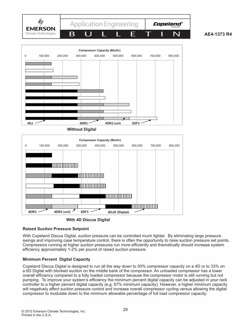
Example #2 Consider the following suction group (the approximate compressor capacity at the ARI rating point is listed next to the compressor model number):
1. 4DJ3R28ML-TSK (280,000 BTUH)2. 4DR3R28ML-TSK (280,000 BTUH) - 1 Bank Unl3. 3DF3R15ML-TFD (150,000 BTUH)
Based on the above guideline, the fi rst compressor should be upgraded to 4D Discus2. The fi gures on the following page show both the staging with and without digital; each box represents a compressor stage. The digital compressor is indicated by the box with vertical cross-hatching for the variable capacity control from 50 -100%.
29© 2012 Emerson Climate Technologies, Inc.Printed in the U.S.A.
AE4-1373 R4
Application Engineering
B U L L E T I N
Raised Suction Pressure SetpointWith Copeland Discus Digital, suction pressure can be controlled much tighter. By eliminating large pressure swings and improving case temperature control, there is often the opportunity to raise suction pressure set points. Compressors running at higher suction pressures run more effi ciently and theoretically should increase system effi ciency approximately 1-2% per pound of raised suction pressure.
Minimum Percent Digital CapacityCopeland Discus Digital is designed to run all the way down to 50% compressor capacity on a 4D or to 33% on a 6D Digital with blocked suction on the middle bank of the compressor. An unloaded compressor has a lower overall effi ciency compared to a fully loaded compressor because the compressor motor is still running but not pumping. To improve your system’s effi ciency the minimum percent digital capacity can be adjusted in your rack controller to a higher percent digital capacity (e.g. 67% minimum capacity). However, a higher minimum capacity will negatively affect suction pressure control and increase overall compressor cycling versus allowing the digital compressor to modulate down to the minimum allowable percentage of full load compressor capacity.
0 100,000 200,000 300,000 400,000 500,000 600,000 700,000 800,000
Compressor Capacity (Btu/hr)
4DR3 4DR3 (unl) 3DF34DJ
0 100,000 200,000 300,000 400,000 500,000 600,000 700,000 800,000
Compressor Capacity (Btu/hr)
4DR3 4DR3 (unl) 3DF34DJ
0 100,000 200,000 300,000 400,000 500,000 600,000 700,000 800,000
Compressor Capacity (Btu/hr)
4DR3 4DR3 (unl) 3DF3 4DJD (Digital)
With 4D Discus Digital
Without Digital

30© 2012 Emerson Climate Technologies, Inc.Printed in the U.S.A.
AE4-1373 R4
Application Engineering
B U L L E T I N
Is the stage configured as Digital?
In the suction group setup, change the stage to Dgtl. No
Select Main Menu – Output Definitions. Locate the analog output and select setup. Change the low and high end to 1-5 V.
Is the analog output
configured for 1-5V?
No
Is the correct board and point identified for the analog output?
Identify the correct board and point and reprogram in E2.
Is the minimum variable capacity
setting set to your desired
min. capacity?
In the suction group setup, change the minimum capacity under the variable capacity tab.
Yes
Disable override mode in the E2 from the variable capacity actions menu.
No
Yes
No
Yes
Is the variable capacity in
override mode?
Yes
Yes
Troubleshooting Guide - Digital Compressor Setup in E2
Note:This troubleshooting should only be used as a quick reference guide.Contact Emerson technical support for additional assistance.
For more detailed application information on Discus digital, please visit our online product information for the following application bulletins available at www.emersonclimate.comAE1328 – Digital Compressor ControllerAE1355 – Digital Capacity Control for Copeland and Intelligent Store Discus Refrigeration Compressors
31© 2012 Emerson Climate Technologies, Inc.Printed in the U.S.A.
AE4-1373 R4
Application Engineering
B U L L E T I N
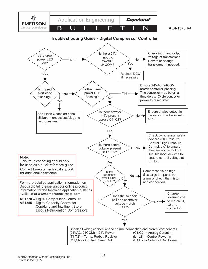
Is the green power LED
on? No
Yes
Check input and output voltage at transformer. Rewire or change transformer if needed.
Is there 24V input to 24VAC,
24COM?
Is the red alert code flashing?
Is the green power LED flashing?
See Flash Codes on panel sticker. If unsuccessful, go to next question.
Yes
No
No
Is there control voltage present
at L1, L2?
Yes
No
Check compressor safety devices (Oil Pressure Control, High Pressure Control, etc) to ensure they are not on lockout. Troubleshoot devices to ensure control voltage at L1, L2.
Change solenoid coil to match L1, L2 and contactor.
Does the solenoid coil and contactor
voltage match L1,L2?
No
Is the resistance
over T1,T2 >
2.58kΩ?
No
Yes
Yes
Compressor is on high discharge temperature alarm or check thermistor and connection.
Yes
Check all wiring connections to ensure connection and correct components. (24VAC, 24COM) = 24V Power (C1,C2) = Analog Output In (T1,T2) = Temp. Probe / Resistor (L1,L2) = Control Power In (M1,M2) = Control Power Out (U1,U2) = Solenoid Coil Power
Ensure analog output in the rack controller is set to 1-5V.
No
Yes
Ensure 24VAC, 24COM match controller phasing. The controller may be on a time delay. Cycle controller power to reset timer.
Is there always 1-5V present
across C1, C2?
Yes
No
Replace DCC if necessary.
Troubleshooting Guide - Digital Compressor Controller
Note:This troubleshooting should only be used as a quick reference guide.Contact Emerson technical support for additional assistance.
For more detailed application information on Discus digital, please visit our online product information for the following application bulletins available at www.emersonclimate.comAE1328 – Digital Compressor ControllerAE1355 – Digital Capacity Control for Copeland and Intelligent Store Discus Refrigeration Compressors
32© 2012 Emerson Climate Technologies, Inc.Printed in the U.S.A.
AE4-1373 R4
Application Engineering
B U L L E T I N
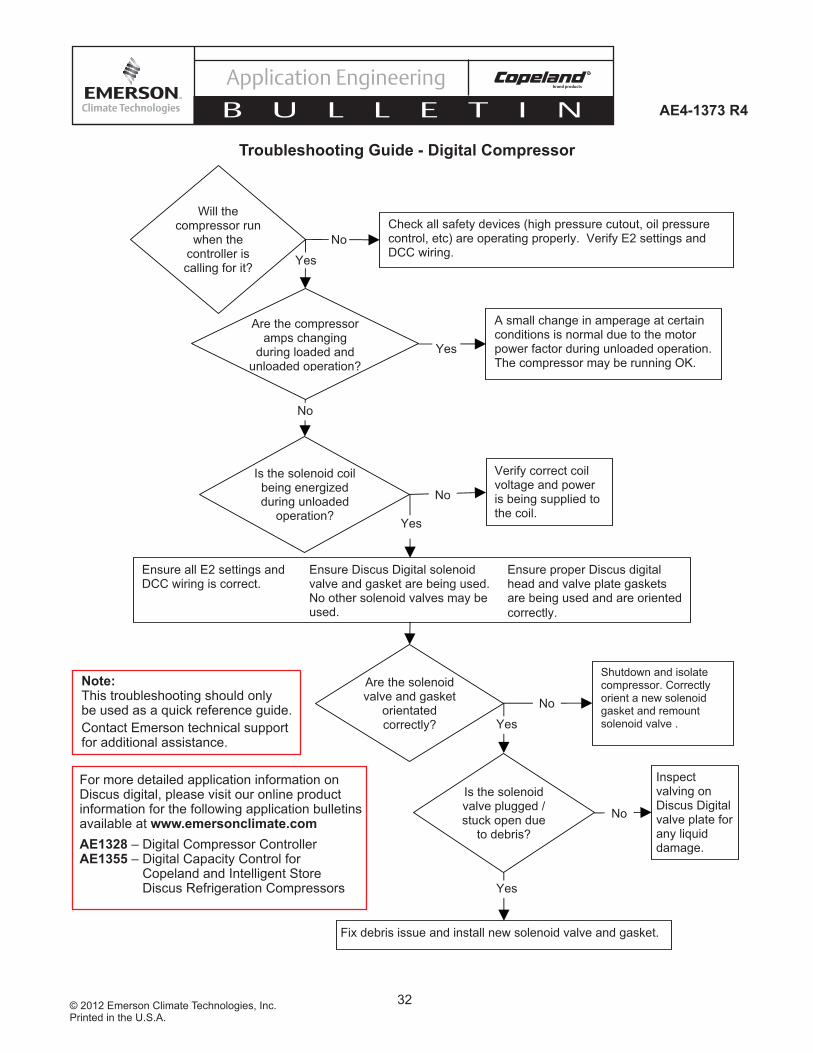
Will the compressor run
when the controller is calling for it?
Check all safety devices (high pressure cutout, oil pressure control, etc) are operating properly. Verify E2 settings and DCC wiring.
No
Yes
Are the compressor amps changing
during loaded and unloaded operation?
A small change in amperage at certain conditions is normal due to the motor power factor during unloaded operation. The compressor may be running OK.
Yes
No
Verify correct coil voltage and power is being supplied to the coil.
Is the solenoid coil being energized during unloaded
operation?
No
Yes
Ensure all E2 settings and DCC wiring is correct.
Ensure Discus Digital solenoid valve and gasket are being used. No other solenoid valves may be used.
Ensure proper Discus digital head and valve plate gaskets are being used and are oriented
correctly.
Are the solenoid valve and gasket
orientated correctly?
Shutdown and isolate compressor. Correctly orient a new solenoid gasket and remount solenoid valve .
No
Yes
Inspect valving on Discus Digital valve plate for any liquid damage.
Is the solenoid valve plugged / stuck open due
to debris?
No
Yes
Fix debris issue and install new solenoid valve and gasket.
Troubleshooting Guide - Digital Compressor
Note:This troubleshooting should only be used as a quick reference guide.Contact Emerson technical support for additional assistance.
For more detailed application information on Discus digital, please visit our online product information for the following application bulletins available at www.emersonclimate.comAE1328 – Digital Compressor ControllerAE1355 – Digital Capacity Control for Copeland and Intelligent Store Discus Refrigeration Compressors