Application descriptiony 03/2015 Configuration of ...
72
https://support.industry.siemens.com/cs/ww/en/view/28430682 Application description 03/2015 Configuration of redundant I/O Modules in SIMATIC PCS 7
Transcript of Application descriptiony 03/2015 Configuration of ...
https://support.industry.siemens.com/cs/ww/en/view/28430682
Application description 03/2015
Configuration of redundantI/O Modules inSIMATIC PCS 7

Warranty and liability
Configuration of Redundant I/O ModulesEntry-ID: 28430682, V2.0, 03/2015 2
Sie
men
sA
G20
15A
llrig
hts
rese
rved
Warranty and liability
Note The Application Examples are not binding and do not claim to be completeregarding the circuits shown, equipping and any eventuality. The ApplicationExamples do not represent customer-specific solutions. They are only intendedto provide support for typical applications. You are responsible for ensuring thatthe described products are used correctly. These application examples do notrelieve you of the responsibility to use safe practices in application, installation,operation and maintenance. When using these Application Examples, yourecognize that we cannot be made liable for any damage/claims beyond theliability clause described. We reserve the right to make changes to theseApplication Examples at any time without prior notice.If there are any deviations between the recommendations provided in theseapplication examples and other Siemens publications – e.g. Catalogs – thecontents of the other documents have priority.
We do not accept any liability for the information contained in this document.
Any claims against us – based on whatever legal reason – resulting from the use ofthe examples, information, programs, engineering and performance data etc.,described in this Application Example shall be excluded. Such an exclusion shallnot apply in the case of mandatory liability, e.g. under the German Product LiabilityAct (“Produkthaftungsgesetz”), in case of intent, gross negligence, or injury of life,body or health, guarantee for the quality of a product, fraudulent concealment of adeficiency or breach of a condition which goes to the root of the contract(“wesentliche Vertragspflichten”). The damages for a breach of a substantialcontractual obligation are, however, limited to the foreseeable damage, typical forthe type of contract, except in the event of intent or gross negligence or injury tolife, body or health. The above provisions do not imply a change of the burden ofproof to your detriment.
Any form of duplication or distribution of these Application Examples or excerptshereof is prohibited without the expressed consent of the Siemens AG.
Securityinforma-tion
Siemens provides products and solutions with industrial security functions thatsupport the secure operation of plants, solutions, machines, equipment and/ornetworks. They are important components in a holistic industrial securityconcept. With this in mind, Siemens’ products and solutions undergo continuousdevelopment. Siemens recommends strongly that you regularly check forproduct updates.
For the secure operation of Siemens products and solutions, it is necessary totake suitable preventive action (e.g. cell protection concept) and integrate eachcomponent into a holistic, state-of-the-art industrial security concept. Third-partyproducts that may be in use should also be considered. For more informationabout industrial security, visit http://www.siemens.com/industrialsecurity.
To stay informed about product updates as they occur, sign up for a product-specific newsletter. For more information, visithttp://support.industry.siemens.com.
Preface
Configuration of Redundant I/O ModulesEntry-ID: 28430682, V2.0, 03/2015 3
Sie
men
sA
G20
15A
llrig
hts
rese
rved
PrefacePurpose of this documentation
Based on PCS 7 applications, this document describes: Redundant I/O modules, especially with channel-granular functionality Installation, wiring and configuration of redundant ET 200M stations The use of MTA terminal modules (Marshalled Termination Assemblies) as
an interface between the distributed I/O modules and the actuators or sensors Diagnostic options on a fault-tolerant system with redundant peripherals in
case of error
Basic knowledge requiredThis documentation is intended for persons involved in configuration,commissioning and servicing of automation systems and who have basicknowledge of SIMATIC PCS 7.
ValidityValid from SIMATIC PCS 7 V8.1.

Preface
Configuration of Redundant I/O ModulesEntry-ID: 28430682, V2.0, 03/2015 4
Sie
men
sA
G20
15A
llrig
hts
rese
rved
Position in the information landscapeYou can find further information regarding the subject of redundancy in PCS 7 andfor dealing directly with the different high-availability components in the followingdocuments.
Document Content
SIMATIC Process Control System PCS 7Released modules
Approved SIMATIC modules for PCS 7 V8.1
SIMATIC Process Control System PCS 7Fault-tolerant Process Control Systems
Solutions for the peripherals Designing high-availability components
SIMATIC Fault-tolerant systems S7-400H Installing a CPU 41x-H Connecting redundant I/O
SIMATIC Distributed I/O device ET 200M Installing the ET 200MSIMATIC S7-300 S7-300 Module data Technical specifications about the signal modulesET 200M Marshalled Termination AssembliesRemote I/O Modules
Commissioning the MTA boards
SIMATIC PCS 7 Process Control SystemAdvanced Process Library
Description of the PCS 7 channel blocks
PCS 7 in Practice - Plant Asset Management Passivation/depassivation of redundant modules
SIMATIC ET 200M distributed I/O deviceHART analog modules
Connecting actuators/sensors inredundant mode
NOTE You can find the sources listed in the table in the Industry Online Support Portal(https://support.industry.siemens.com).

Table of contents
Configuration of Redundant I/O ModulesEntry-ID: 28430682, V2.0, 03/2015 5
Sie
men
sA
G20
15A
llrig
hts
rese
rved
Table of contentsWarranty and liability ............................................................................................... 2Preface ...................................................................................................................... 31 Introduction .................................................................................................... 6
1.1 Redundant I/O ................................................................................... 61.2 Behavior in case of channel interference ............................................ 61.3 Hardware components ....................................................................... 71.3.1 High-availability automation system (AS) ........................................... 81.3.2 Interface modules (IM) ....................................................................... 91.3.3 Bus modules.................................................................................... 101.3.4 Input/output module (I/O) ................................................................. 111.3.5 MTA (Marshalled Termination Assemblies) terminal module ............ 12
2 Configuring and wiring ................................................................................ 15
2.1 Redundant PROFIBUS DP connection ............................................ 152.2 Connecting an MTA terminal module ............................................... 152.3 Redundant connections of the distributed I/O ................................... 182.3.1 Digital input ..................................................................................... 192.3.2 Digital output ................................................................................... 222.3.3 Analog input .................................................................................... 252.3.4 Analog output .................................................................................. 32
3 Configuring the redundant peripherals ....................................................... 38
3.1 CPU settings ................................................................................... 383.2 Configuring the ET 200M (IM 153-2 interface module) ..................... 413.3 Configuring the signal modules ........................................................ 423.4 Configuring the second ET 200M ..................................................... 463.5 Signal module settings ..................................................................... 483.6 Additional parameter settings for the configuration of the
redundant AI modules ...................................................................... 513.7 Configuring the HART field devices .................................................. 553.8 Symbolic name assignment ............................................................. 563.9 CFC configuration ............................................................................ 58
4 Function mechanisms .................................................................................. 60
4.1 Example of a flowchart..................................................................... 604.2 Library functions .............................................................................. 624.2.1 PCS 7 Basic Library V8.1 ................................................................ 624.2.2 Redundant IO CGP V5.2 ................................................................. 624.3 OS messages of the modules .......................................................... 63
5 Diagnostics ................................................................................................... 65
5.1 Failure scenario ............................................................................... 655.2 OS messages .................................................................................. 665.3 Asset management .......................................................................... 675.4 HW Config Online ............................................................................ 685.5 CFC test mode ................................................................................ 70
6 Related literature .......................................................................................... 727 History .......................................................................................................... 72

1 Introduction1.1 Redundant I/O
Configuration of Redundant I/O ModulesEntry-ID: 28430682, V2.0, 03/2015 6
Sie
men
sA
G20
15A
llrig
hts
rese
rved
1 Introduction1.1 Redundant I/O
The high-availability in PCS 7 is basically applicable to all levels. In thisdocumentation, the focus lies on the application of redundant distributed I/O usingET 200M modules. It explains with particular emphasis the wiring options of theinput/output modules as well as the individual configuration steps.The term I refers to input/output (I/O) modules, which are duplicated andconfigured/operated redundantly in pairs. If a module fails, a CPU or process signalcan be processed by the operational module. The entire signal path to thesensor/actuator is redundant.As interface modules, the MTA terminal modules (Marshalled TerminationAssemblies) offer the possibility of connecting field devices, sensors and actuatorsin a simple, quick and safe manner to the input/output modules of the ET 200M.The document shows how such MTA are structured, what important features andadvantages they possess, and how the implementation can be carried out withoutcomplicated wiring and configuration.
Note The manual "SIMATIC Fault-tolerant systems S7-400H" provides extensiveinformation about the redundancy mechanisms in the AS level.
1.2 Behavior in case of channel interference
The passivation behavior determines how redundant input/output modules behaveafter a channel fault (e.g. wire break, short-circuit on the signal line). The responseto a channel fault is dependent on the following aspects: Modules used Configuration Version of the PCS 7 library
– As from PCS 7 V7.1, the possible passivation behavior is automaticallydetected based on the configured modules. The channel-granularpassivation behavior is adjusted.
– The library RedLib V3.x only allows the module-granular passivationbehavior to be selected.
– The library RedLib (from V4) enables the channel-granular passivationbehavior to be adjusted.
Channel faults, whether due to discrepancy or due to a diagnostic interrupt (OB82),lead to the passivation of the respective channel. If the fault is cleared, the so-called 'depassivation' activates the channel or the modules passivated due tomodule faults. Channel-granular passivation significantly increases the availabilityin the following cases: Relatively frequent encoder failures Repairs that take a long time Multiple channel errors on one module
1 Introduction1.3 Hardware components
Configuration of Redundant I/O ModulesEntry-ID: 28430682, V2.0, 03/2015 7
Sie
men
sA
G20
15A
llrig
hts
rese
rved
When switching from the "module-granular passivation behavior" (RedLib V3.x) to"channel-granular passivation behavior" (from RedLib V4.x), you must consider thefollowing points: When upgrading from PCS 7 V7.1 SP4 to PCS 7 V8.1 (with utilization of new
functions) new compatible blocks are imported into the project from the library"Redundant IO CGP V52" if using redundant peripherals.
When converting a project, make sure that all blocks with the namesFB450-453 and FC450-451 have been deleted from the block folder.Perform this step in every relevant program. Compile and load your project.
1.3 Hardware components
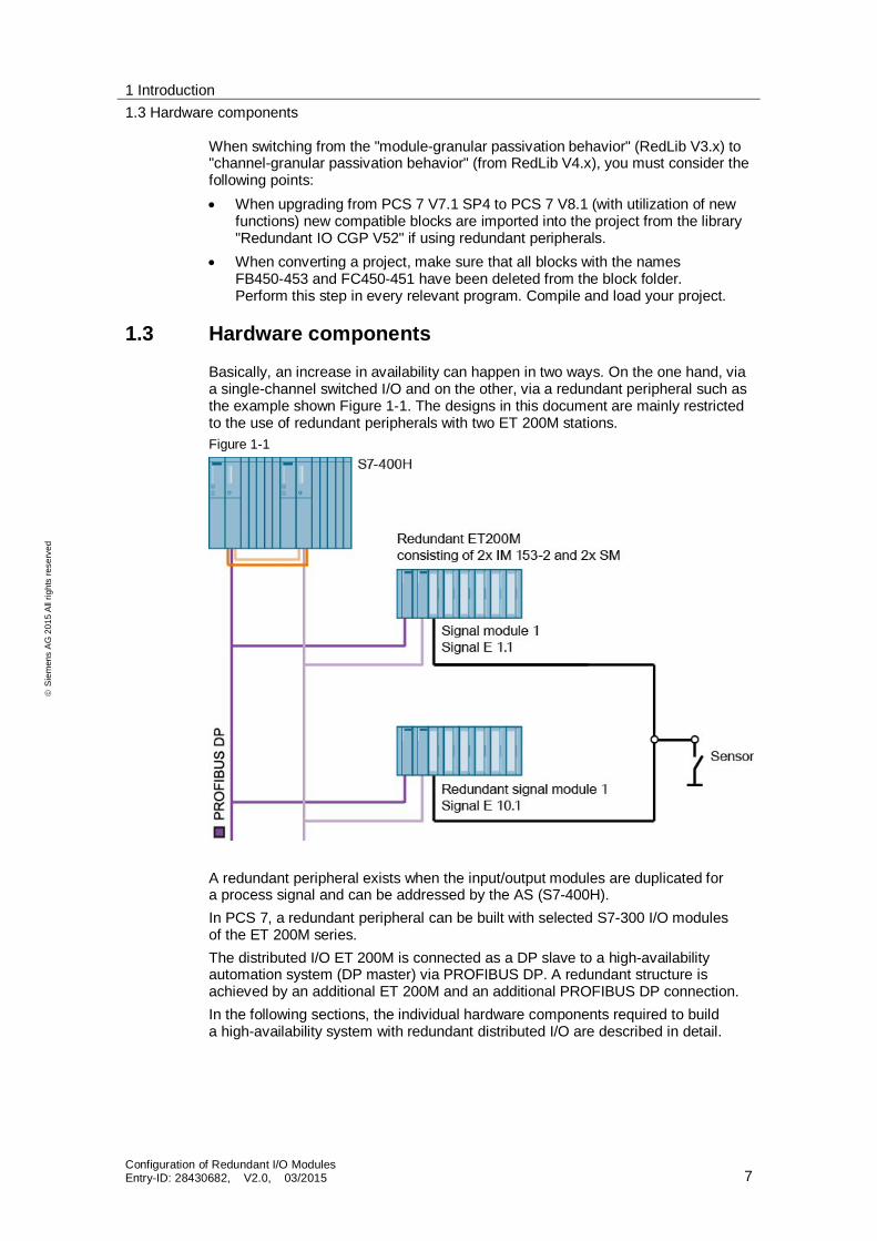
Basically, an increase in availability can happen in two ways. On the one hand, viaa single-channel switched I/O and on the other, via a redundant peripheral such asthe example shown Figure 1-1. The designs in this document are mainly restrictedto the use of redundant peripherals with two ET 200M stations.Figure 1-1
A redundant peripheral exists when the input/output modules are duplicated fora process signal and can be addressed by the AS (S7-400H).In PCS 7, a redundant peripheral can be built with selected S7-300 I/O modulesof the ET 200M series.The distributed I/O ET 200M is connected as a DP slave to a high-availabilityautomation system (DP master) via PROFIBUS DP. A redundant structure isachieved by an additional ET 200M and an additional PROFIBUS DP connection.In the following sections, the individual hardware components required to builda high-availability system with redundant distributed I/O are described in detail.

1 Introduction1.3 Hardware components
Configuration of Redundant I/O ModulesEntry-ID: 28430682, V2.0, 03/2015 8
Sie
men
sA
G20
15A
llrig
hts
rese
rved
1.3.1 High-availability automation system (AS)
Fault-tolerant automation systems are used to minimize the risk of productionfailures.For the S7-400H to remain always available, it is built as a redundant system.This means that all essential components are duplicated, i.e. the central processingunit CPU, power supply and hardware for coupling the two CPUs.Table 1-1: CPU types that can be used starting from PCS 7 V8.1
Name MLFB FW
CPU 410-5H process automation 6ES7 410-5HX08-0AB0 V8.1.xCPU 412-5H PN/DP 6ES7 412-5HK06-0AB0 V6.x
CPU 414-5H PN/DP 6ES7 414-5HM06-0AB0 V6.x
CPU 416-5H PN/DP 6ES7 416-5HS06-0AB0 V6.x
CPU 417-5H PN/DP 6ES7 417-5HT06-0AB0 V6.x

1 Introduction1.3 Hardware components
Configuration of Redundant I/O ModulesEntry-ID: 28430682, V2.0, 03/2015 9
Sie
men
sA
G20
15A
llrig
hts
rese
rved
1.3.2 Interface modules (IM)
Interface modules (IM) are used by the distributed I/O device ET 200M asa PROFIBUS DP interface. With redundant peripherals, one must ensure thattwo interface modules (IMs) are used per ET 200M station and that the same busaddress is set for both modules (via dip switches).This ensures that if the active interface module fails during operation, the passiveinterface module takes over the corresponding function smoothly. The activeinterface is indicated by the lit ACT LED on the respective interface module.Table 1–2: IM module for redundant applications
Name MLFB Product Brief
ET 200M - IM 153-2 6ES7 153-2BA02-0XB0V5.x
Bus interface for S7-300 SMs, FMs(without FM 356-4),module exchange during operation,expansion of the instrumentation andcontrol functions, up to 12 I/O modulescan be operated
ET 200M - IM 153-2 6ES7 153-2BA82-0XB0V5.x
Bus interface for S7-300 SMs(outdoor),FMs (without FM 356-4),module exchange during operation,expansion of the instrumentation andcontrol functions, up to 12 I/O modulescan be operated
ET 200M - IM 153-2 6ES7 153-2BA70-0XB0 Bus interface for S7-300 SMs(outdoor); FMs (without FM 356-4),module exchange during operation, upto 12 I/O modules can be operated

1 Introduction1.3 Hardware components
Configuration of Redundant I/O ModulesEntry-ID: 28430682, V2.0, 03/2015 10
Sie
men
sA
G20
15A
llrig
hts
rese
rved
1.3.3 Bus modules
As mentioned above, in PCS 7 only active bus modules can be used for redundantapplications with ET 200M. This enables removal and insertion of modules duringoperation. To achieve redundant operation, each ET 200M requires two interfacemodules IM 153-2 high feature to be mounted on the active bus module.For the ET 200M standard modules (e.g. DI, DO, AI, AO), further bus modules areused.Figure 1–2: Possible configuration of an ET 200M station. It should be noted that the use of
the redundant power supply module (PS) is optiona
Note For more information about the permitted combination of interfaces and busmodules, as well as available functionalities, please refer to the manual "SIMATIC Distributed I/O device ET 200M ".
In practice, an IM 153 redundancy bundle is often ordered for the installation ofa redundant ET 200M station. This consists of two IM 153-2 high feature and oneactive bus module IM 153/IM 153.
PSPS
PS

1 Introduction1.3 Hardware components
Configuration of Redundant I/O ModulesEntry-ID: 28430682, V2.0, 03/2015 11
Sie
men
sA
G20
15A
llrig
hts
rese
rved
1.3.4 Input/output module (I/O)
I/O modules with channel-granular functionalityFrom PCS 7 V7.0 upwards, you can specify how redundant input/output modulesbehave in case of a channel fault (e.g. wire break, short circuit on the signal line).For a channel fault, one can expect the following reactions depending on themodule used and the configuration: If a fault occurs, only the faulty channel is passivated (recommended channel-
granular passivation)
The entire module is passivated when a fault occurs (module-granularpassivation)
The following Table 1–3 shows input and output modules, which are suitable forthe redundant configuration with ET 200M and equipped with channel-granularfunctionality. It should be noted that modules with channel-granular properties canbe also always used for module-granular functionality but not the other way round.Table 1–3
Name MLFB
Digital input module SM321
DI 16x24 V DC, interrupt 6ES7 321-7BH01-0AB0DI 16xDC24V, Alarm; high feature 6ES7 321-7BH01-0AB0 ES 6 (revision)DI 4xNAMUR,Ex 6ES7 321-7RD00-0AB0DI 16xNAMUR 6ES7 321-7TH00-0AB0
Digital output module SM322DO 8xDC24V/2A 6ES7 322-1BF01-0AA0DO 4xDC24V/10mA, Ex 6ES7 322-5SD00-0AB0
Analog input modules SM331AI 8x16Bit 6ES7 331-7NF00-0AB0AI 8x16Bit 6ES7 331-7NF10-0AB0AI 6xTC 6ES7 331-7PE10-0AB0AI 4x0/4...20mA, Ex 6ES7 331-7RD00-0AB0AI 8x0/4…20mA HART 6ES7 331-7TF01-0AB0
Analog output modules SM332AO 4x12Bit 6ES7 332-5HD01-0AB0AO 8x12Bit 6ES7 332-5HF00-0AB0AO 4x0/4...20mA,Ex 6ES7 332-5RD00-0AB0AO 8x0/4…20mA HART 6ES7 332-8TF01-0AB0
Note When using HART modules, you have to use PCS 7 from V7.0 SP1. Specificinterface modules (6ES7 153-2BA02-0XB0 or 6ES7 153-2BA82-0XB0) mustalso be used.

1 Introduction1.3 Hardware components
Configuration of Redundant I/O ModulesEntry-ID: 28430682, V2.0, 03/2015 12
Sie
men
sA
G20
15A
llrig
hts
rese
rved
Special features of HART modules
Note When using redundant HART analog input modules, only one transmitter(encoder) can be connected.
Redundant HART signal modules work as "Primary Master" and "SecondaryMaster" to allow simultaneous HART communication via both modules with a fielddevice.The system declares the module with the lower address as the "Primary Master".If this one fails, communication happens via the"Secondary Master".
Note In order not to affect this system behavior, no other HART Master, e.g. handheld,may be connected.
1.3.5 MTA (Marshalled Termination Assemblies) terminal module
The MTA terminal modules offer the possibility of connecting field devices, sensorsand actuators easily and quickly to the I/O modules of the distributed I/O ET 200M.The MTA are each tailored to specific I/O modules from the ET 200M range. MTAversions for standard I/O modules are also available for redundant and safety-related I/O modules.They can be used to significantly reduce the costs and required work for cablingand commissioning, and prevent wiring errors.The following figure illustrates the capabilities of MTA together with ET 200Mstations (with an encoder).Figure 1–3
The MTA terminal modules are connected to the I/O modules of the ET 200M via3m or 8m long pre-assembled cables.

1 Introduction1.3 Hardware components
Configuration of Redundant I/O ModulesEntry-ID: 28430682, V2.0, 03/2015 13
Sie
men
sA
G20
15A
llrig
hts
rese
rved
Product featuresMTA are characterized by the following properties: Redundant 24 V DC power supply with LED display Screw-type terminals for direct (1:1) connection of field devices, sensors and
actuators Fuse with LED indicator for each I/O channel Pre-assembled cables to connect the MTA with the I/O module with SUB D connector, 50/25-pin, plug socket version, for MTA with Siemens front connector, 40/20-pin, plug socket version, for the ET 200M
module On-board simulation capabilities for IBS purposes (wire break, to switch
ON/OFF a channel) Tested as a SIMATIC PCS 7 system component and approved with
appropriate approvals (FM, UL, CE, ATEX, TÜV (German TechnicalInspectorate))
Advantages MTA allow quick and simple wiring to field devices Direct connection of field devices SUB D connector to connect pre-assembled cables A backup for each channel with LED display Redundant 24 V DC power supply On-board simulation capabilities, e.g. for commissioning purposes Support for redundant ET 200M modules Channel-granular protection Cables must be accessible Internal potential distribution Easy maintenance with plug connections Faster commissioning Connection possibility for HART modem to the MTA
Note For more detailed information, refer to the "ET 200M Marshalled TerminationAssemblies Remote I/O Modules".

1 Introduction1.3 Hardware components
Configuration of Redundant I/O ModulesEntry-ID: 28430682, V2.0, 03/2015 14
Sie
men
sA
G20
15A
llrig
hts
rese
rved
In the case of the MTA, please note that an MTA module can only be connectedwith certain input/output modules. Table 1–4 shows possible connectionpossibilities.Table 1–4
Product label MLFB8 channels, AI 6ES7650-1AA52-2XX08 channels, AO 6ES7650-1AB51-2XX0
8 channels, AI HART 6ES7650-1AA61-2XX08 channels, AO HART 6ES7650-1AB61-2XX0
8 channels, AI TC 6ES7650-1AF51-2XX08 channels, AI RTD 6ES7650-1AG51-2XX0
16 channels, DO 6ES7650-1AD11-2XX06 channels F-AI HART
(safety-related)6ES7650-1AH62-5XX0
16 channels, DI 6ES7650-1AC11-3XX024 channels F-DI(safety-related)
6ES7650-1AK11-7XX0
10 channels F-DO(safety-related)
6ES7650-1AL11-6XX0
16 channels DO relay 6ES7650-1AM30-3XX010 channels F-DO
Relay (safety-related)6ES7650-1AM31-6XX0
Note For detailed information about each MTA type, please refer to the productrelease: https://support.industry.siemens.com/cs/ww/en/view/29289048

2 Configuring and wiring2.1 Redundant PROFIBUS DP connection
Configuration of Redundant I/O ModulesEntry-ID: 28430682, V2.0, 03/2015 15
Sie
men
sA
G20
15A
llrig
hts
rese
rved
2 Configuring and wiring2.1 Redundant PROFIBUS DP connection
The transition from the automation system to PROFIBUS DP is done viaa CP 443-5 Extended or via one of the two internal PROFIBUS DP interfacesof the CPU.
2.2 Connecting an MTA terminal module
MTA provide quick and easy connection of the field level to the ET 200MI/O modules. They reduce the amount of wiring effort and avoid mistakes.Figure 2-1
Note To achieve maximum availability with redundant encoders, two MTA are alsorequired, each being connected between the input modules and the encoders.

2 Configuring and wiring2.2 Connecting an MTA terminal module
Configuration of Redundant I/O ModulesEntry-ID: 28430682, V2.0, 03/2015 16
Sie
men
sA
G20
15A
llrig
hts
rese
rved
The connection of the ET 200M modules to the MTA is established via theconnecting cable of the correct type, as also shown in the following figure withan MTA AI as an example.Figure 2–2
Preassembled cable with SUB-Dconnector for connection to SIEMENSPCS 7 MTA
Screwing terminalsfor direct connectionto field devices
2 connections forredundant construction
Preassembled cable with SUB-Dconnector for connection to SIEMENSPCS 7 MTA
Screwing terminalsfor direct connectionto field devices
2 connections forredundant construction

2 Configuring and wiring2.2 Connecting an MTA terminal module
Configuration of Redundant I/O ModulesEntry-ID: 28430682, V2.0, 03/2015 17
Sie
men
sA
G20
15A
llrig
hts
rese
rved
Connection example of sensors to the screw-type terminals on the MTAThe following figure shows the encoder connection using the example of digitalinputs.Figure 2–3
Note For more detailed information, refer to the "ET 200M Marshalled TerminationAssemblies Remote I/O Modules".
Anschluss Kanal 1
Anschluss Kanal 13
Connection channel 1
Connection channel 13
Anschluss Kanal 1
Anschluss Kanal 13
Connection channel 1
Connection channel 13

2 Configuring and wiring2.3 Redundant connections of the distributed I/O
Configuration of Redundant I/O ModulesEntry-ID: 28430682, V2.0, 03/2015 18
Sie
men
sA
G20
15A
llrig
hts
rese
rved
2.3 Redundant connections of the distributed I/O
Figure 2–4 shows an example of the redundant peripherals connection, switchedin the DP slave mode. In contrast to the redundant peripherals in the one-sided DPslave mode, the signal modules in the ET 200M distributed I/O devices are herebyused in pairs.Figure 2–4
The following chapters describe how to connect the sensor to the signal modules.
Note For detailed diagrams and assembly data, refer to the manual "SIMATIC S7-300S7-300 Module data".
Specific notes for the redundant use of certain signal modules, can be found inthe manual "SIMATIC Fault-tolerant systems S7-400H" or in the manual"SIMATIC PCS 7 process control system CPU 410-5H Process Automation"
Redundant module pair

2 Configuring and wiring2.3 Redundant connections of the distributed I/O
Configuration of Redundant I/O ModulesEntry-ID: 28430682, V2.0, 03/2015 19
Sie
men
sA
G20
15A
llrig
hts
rese
rved
2.3.1 Digital input
Sensor connectionOne or two sensors are connected to two redundant SM 321; DI 16 x DC 24 V(1 of 2 structure).Figure 2-5
To achieve maximum availability, it is recommended to use two encoders.
Note When connecting an encoder to several digital input modules, the redundantmodules must operate at the same reference potential.
With one encoder With two encoders

2 Configuring and wiring2.3 Redundant connections of the distributed I/O
Configuration of Redundant I/O ModulesEntry-ID: 28430682, V2.0, 03/2015 20
Sie
men
sA
G20
15A
llrig
hts
rese
rved
Connection and schematic circuit diagram of the SM 321; DI 16 x DC 24 VThe following picture shows the schematic circuit diagram of the digital inputmodule with channel-granular functionality (6ES7 321-7BH01-0AB0).Figure 2–6
Table 2–1
Digit Description
1 Channel number2 Status displays – green
Fault display – redEncoder supply VS – green
3 Backplane bus interface4 Open-circuit detection

2 Configuring and wiring2.3 Redundant connections of the distributed I/O
Configuration of Redundant I/O ModulesEntry-ID: 28430682, V2.0, 03/2015 21
Sie
men
sA
G20
15A
llrig
hts
rese
rved
ExampleAn encoder is connected to channel 0 of each of the two SM 321; DI 16 x DC 24 V:Figure 2–2

2 Configuring and wiring2.3 Redundant connections of the distributed I/O
Configuration of Redundant I/O ModulesEntry-ID: 28430682, V2.0, 03/2015 22
Sie
men
sA
G20
15A
llrig
hts
rese
rved
2.3.2 Digital output
Controlling the final element controlThe actuator is connected to two redundant SM322; DO 16 x DC 24 V / 0.5 A(1 of 2 structure). Depending on the type of digital output modules, additionaldiodes must be used in redundant mode.
Note You can find the overview about which digital output modules you have tointerconnect via external diodes in table 8-4 of the manual "S7-400H AutomationSystem, High-availability Systems".
Figure 2–7
The digital output module with channel-granular functionality(6ES7 322-8BH01-0AB0) is interconnected without external diodes.
Note The digital output modules must be connected to a common load voltage supply.
With external diodes Diodes integrated into the module
Actuator

2 Configuring and wiring2.3 Redundant connections of the distributed I/O
Configuration of Redundant I/O ModulesEntry-ID: 28430682, V2.0, 03/2015 23
Sie
men
sA
G20
15A
llrig
hts
rese
rved
Connection and schematic circuit diagram of the SM 322; DO 16 x DC 24 V / 0.5 AThe following picture shows the schematic circuit diagram of the digital outputmodule with channel-granular functionality (6ES7 322-8BH01-0AB0).Figure 2–5
Table 2–2
Digit Description
1 Status displays (green)Fault display (red)
2 Channel numberThe numbers 0 to 7 on the right side are the channel numbers 8 to 15
3 Channel status (green)4 Channel fault (red)
2 Configuring and wiring2.3 Redundant connections of the distributed I/O
Configuration of Redundant I/O ModulesEntry-ID: 28430682, V2.0, 03/2015 24
Sie
men
sA
G20
15A
llrig
hts
rese
rved
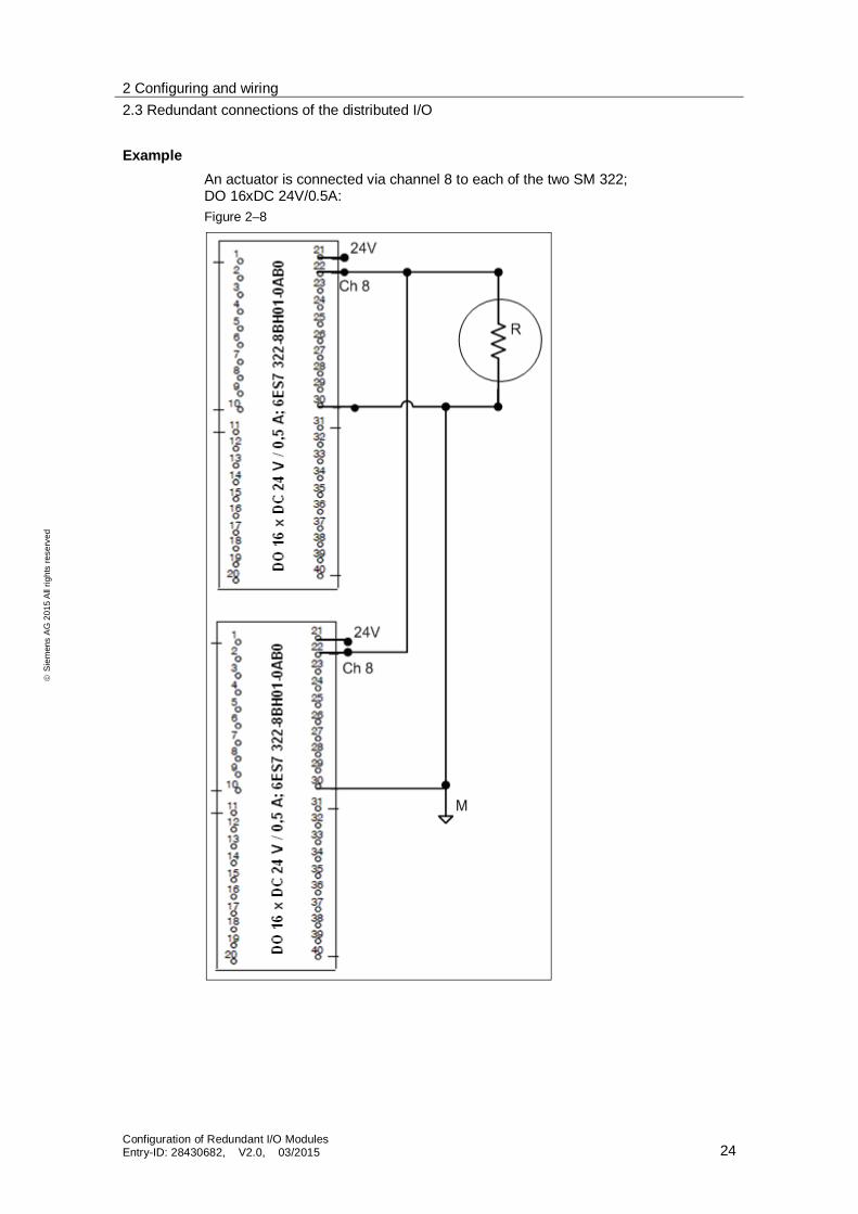
ExampleAn actuator is connected via channel 8 to each of the two SM 322;DO 16xDC 24V/0.5A:Figure 2–8

2 Configuring and wiring2.3 Redundant connections of the distributed I/O
Configuration of Redundant I/O ModulesEntry-ID: 28430682, V2.0, 03/2015 25
Sie
men
sA
G20
15A
llrig
hts
rese
rved
2.3.3 Analog input
Encoder connectionThe analog input module SM331; AI 8x16 bit can be used with one or twoencoders in redundant operation (1 of 2 structure).Figure 2–9
To achieve maximum availability, it is recommended to use redundant encoders.
Note When using redundant HART analog input modules, only one transmitter(encoder) can be connected.
With voltage encoder With current encoder (direct)
With current encoder (indirect)
With two encoders

2 Configuring and wiring2.3 Redundant connections of the distributed I/O
Configuration of Redundant I/O ModulesEntry-ID: 28430682, V2.0, 03/2015 26
Sie
men
sA
G20
15A
llrig
hts
rese
rved
Connection and schematic circuit diagram of the SM 331; AI 8 x 16 bit (voltagemeasurement)
The following two pictures each show the schematic circuit diagram of the analoginput module SM331 AI 8x16 bit (6ES7 331-7NF00-0AB0) with channel-granularfunctionality for voltage and current measurement.Figure 2–10
Table 2–3
Digit Description
1 Voltage measurement2 Backplane bus interface3 Electrical isolation4 Analog-to-Digital Converter (ADC)5 Equipotential bonding

2 Configuring and wiring2.3 Redundant connections of the distributed I/O
Configuration of Redundant I/O ModulesEntry-ID: 28430682, V2.0, 03/2015 27
Sie
men
sA
G20
15A
llrig
hts
rese
rved
Connection and schematic circuit diagram of the SM 331; AI 8 x 16 bit (currentmeasurement)
For current measurements, the voltage terminals are closed in parallel with thecorresponding current sensing resistor. Bridge the channel input terminals withthe adjacent connector terminals.For example, to configure channel 0 for the current measurement, you have tobridge the terminals 22 and 2 and the terminals 23 and 3.At the channel configured for current measurements, connect the current sensingresistor to the adjacent channel terminals in order to achieve the specifiedprecision.4-wire transducer (channel 0) or2-wire transducer with external power supply (channel 7)Figure 2–11

2 Configuring and wiring2.3 Redundant connections of the distributed I/O
Configuration of Redundant I/O ModulesEntry-ID: 28430682, V2.0, 03/2015 28
Sie
men
sA
G20
15A
llrig
hts
rese
rved
Table 2–4
Digit Description
1 Backplane bus interface2 Electrical isolation3 Analog-to-Digital Converter (ADC)4 CH 0 for 4-wire transducer5 CH 7 for 2-wire transducer (with external supply)6 Equipotential bonding
Connection and schematic circuit diagram of the SM 331; AI 8 x 0/4…20 mA HARTThe following picture shows the schematic circuit diagram of the analog HARTinput module SM331 AI 8x0/4...20 mA (6ES7 331-7TF01-0AB0) with channel-granular functionality.
Figure 2–12

2 Configuring and wiring2.3 Redundant connections of the distributed I/O
Configuration of Redundant I/O ModulesEntry-ID: 28430682, V2.0, 03/2015 29
Sie
men
sA
G20
15A
llrig
hts
rese
rved
Example of an SM 331; AI 8 x 16 bitThe following figure shows the connection of a transmitter to two AI 8 x 16 bitmodules for the voltage measurement.Figure 2–13

2 Configuring and wiring2.3 Redundant connections of the distributed I/O
Configuration of Redundant I/O ModulesEntry-ID: 28430682, V2.0, 03/2015 30
Sie
men
sA
G20
15A
llrig
hts
rese
rved
Example of an SM 331; AI 8x0/4…20 mA HART (2-wire transducer)
Note A 2-wire transducer must be connected and configured to two redundant HARTanalog input modules as a 4-wire transducer.
You can find more detailed information in the manual "Distributed I/O DeviceET 200M HART Analog Modules".
The terminals 10 and 11 may not be connected to the front connector(see Figure 2–12).Figure 2–14
The interconnected Zener diodes are required if the system is to continuefunctioning while dragging a module.

2 Configuring and wiring2.3 Redundant connections of the distributed I/O
Configuration of Redundant I/O ModulesEntry-ID: 28430682, V2.0, 03/2015 31
Sie
men
sA
G20
15A
llrig
hts
rese
rved
Example of an SM 331; AI 8x0/4…20 mA HART (4-wire transducer)A 4-wire transducer is connected to two redundant HART analog input modules:Figure 2–15
The interconnected Zener diodes are required if the system is to continuefunctioning while dragging a module.

2 Configuring and wiring2.3 Redundant connections of the distributed I/O
Configuration of Redundant I/O ModulesEntry-ID: 28430682, V2.0, 03/2015 32
Sie
men
sA
G20
15A
llrig
hts
rese
rved
2.3.4 Analog output
Controlling the final element controlFor the high-availability control of a final controlling element, two outputs of twoSM 332; AO 8x12 bit are switched in parallel via diodes (1 of 2 structure).Only analog output modules with current outputs can be operated redundantly(0 to 20 mA or 4 to 20 mA).Figure 2–16
Each of both outputs transmits half the value. If one of the modules fails, the otheroutput transmits the full value.
Finalcontrollingelement

2 Configuring and wiring2.3 Redundant connections of the distributed I/O
Configuration of Redundant I/O ModulesEntry-ID: 28430682, V2.0, 03/2015 33
Sie
men
sA
G20
15A
llrig
hts
rese
rved
Connection and schematic circuit diagram of the SM 332; AO 8 x 12 bit (voltage output)The following picture shows the schematic circuit diagram of the analog outputmodule SM332 AO 8x12 bit (6ES7 332-5HF00-0AB0) with channel-granularfunctionality in the 2 and 4-wire connection for voltage output. 2-wire connection without compensation of line resistance
4-wire connection with compensation of line resistanceFigure 2–17
Table 2–5
Digit Description
1 DAC2 Internal supply3 Equipotential bonding4 Functional grounding5 Backplane bus interface6 Electrical isolation

2 Configuring and wiring2.3 Redundant connections of the distributed I/O
Configuration of Redundant I/O ModulesEntry-ID: 28430682, V2.0, 03/2015 34
Sie
men
sA
G20
15A
llrig
hts
rese
rved
Connection and schematic circuit diagram of the SM 332; AO 8 x 12 bit (current output)The following picture shows the schematic circuit diagram of the analog outputmodule SM332 AO 8x12 bit (6ES7 332-5HF00-0AB0) with channel-granularfunctionality as current output.Figure 2–18
Table 2–6
Digit Description
1 DAC2 Internal supply3 Equipotential bonding4 Functional grounding5 Backplane bus interface6 Electrical isolation
2 Configuring and wiring2.3 Redundant connections of the distributed I/O
Configuration of Redundant I/O ModulesEntry-ID: 28430682, V2.0, 03/2015 35
Sie
men
sA
G20
15A
llrig
hts
rese
rved
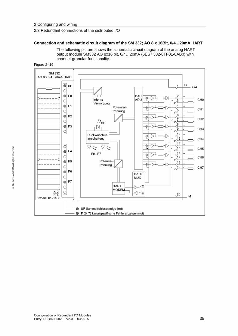
Connection and schematic circuit diagram of the SM 332; AO 8 x 16Bit, 0/4…20mA HARTThe following picture shows the schematic circuit diagram of the analog HARToutput module SM332 AO 8x16 bit, 0/4…20mA (6ES7 332-8TF01-0AB0) withchannel-granular functionality.
Figure 2–19

2 Configuring and wiring2.3 Redundant connections of the distributed I/O
Configuration of Redundant I/O ModulesEntry-ID: 28430682, V2.0, 03/2015 36
Sie
men
sA
G20
15A
llrig
hts
rese
rved
Example of an SM 332; AO 8 x 12 bitThe actuator is connected to channel 0 of each of the two redundant SM 332;AO 8 x 12 bit.
Figure 2–20
Note Suitable diodes include, for example, types from the series 1N4003 ... 1N4007 orany other diode with U_r> = 200 V and I_F> = 1 A.
It makes sense to separate module weight and load weight. There must beequipotential bonding between both.

2 Configuring and wiring2.3 Redundant connections of the distributed I/O
Configuration of Redundant I/O ModulesEntry-ID: 28430682, V2.0, 03/2015 37
Sie
men
sA
G20
15A
llrig
hts
rese
rved
Example of an SM 332; AO 8 x 16Bit, 0/4…20mA HARTThe actuator is connected to two redundant HART analog output modules.Figure 2–21
3 Configuring the redundant peripherals3.1 CPU settings
Configuration of Redundant I/O ModulesEntry-ID: 28430682, V2.0, 03/2015 38
Sie
men
sA
G20
15A
llrig
hts
rese
rved
3 Configuring the redundant peripheralsThe following sections describe the configuration of individual components of thedistributed IO with PCS 7. It is assumed that a PCS 7 project has been alreadycreated with an H station using the Project Wizard.The following configuration steps are described: CPU settings (H parameters)
Configuring the first ET 200M (IM 153-2 interface module)
Configuring the individual signal modules IOs
Configuring the second ET 200M via copying
Redundancy settings at the signal modules
Symbolic name assignment
CFC configuration
3.1 CPU settings
To enable redundant operation between the AS and the distributed I/O, the CPUrequires a certain configuration.
Requirements The PCS 7 project with a SIMATIC H station is opened in SIMATIC Manager.
If channel-granular passivation behavior is required, corresponding signalmodules must be used when configuring the ET 200M (see ch. 1.3).
3 Configuring the redundant peripherals3.1 CPU settings
Configuration of Redundant I/O ModulesEntry-ID: 28430682, V2.0, 03/2015 39
Sie
men
sA
G20
15A
llrig
hts
rese
rved
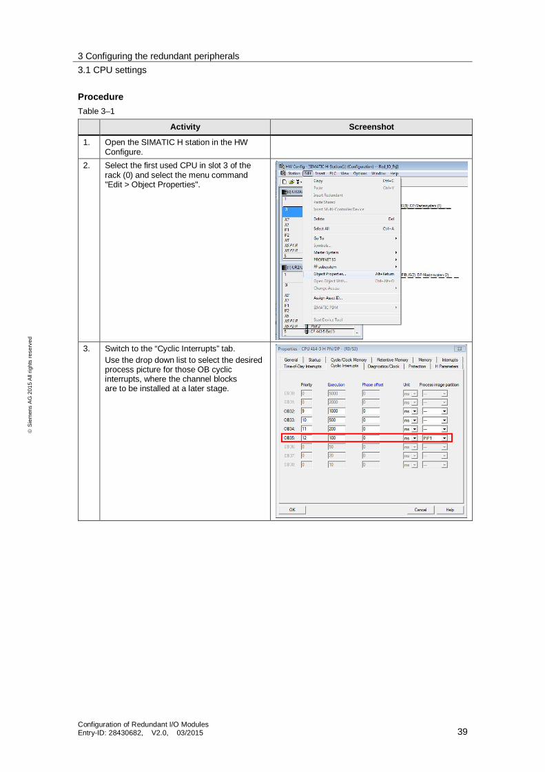
ProcedureTable 3–1
Activity Screenshot
1. Open the SIMATIC H station in the HWConfigure.
2. Select the first used CPU in slot 3 of therack (0) and select the menu command"Edit > Object Properties".
3. Switch to the “Cyclic Interrupts” tab.Use the drop down list to select the desiredprocess picture for those OB cyclicinterrupts, where the channel blocksare to be installed at a later stage.

3 Configuring the redundant peripherals3.1 CPU settings
Configuration of Redundant I/O ModulesEntry-ID: 28430682, V2.0, 03/2015 40
Sie
men
sA
G20
15A
llrig
hts
rese
rved
Activity Screenshot
4. Switch to the "H Parameters" tab.Take note of those data blocks in the field"Data block no.", which are defined as astandard encoder, so that you don't usethem elsewhere in your configuration.In the drop-down list "Passivationbehavior", select the desired setting(channel-granular or module-granular).Click the button "Calculate…" in the field"Update the Standby CPU".These settings are performed to calculatethe monitoring times.
Note:This defines how the redundant input/outputmodules behave in case of channel faults(see chapter 1.4). This setting is intendedfor all redundantly configured signalmodules that are connected to the CPU.
5. Switch to the "Cycle/Clock Memory" tab.Under "OB 85 - call up at I/O access error",select "Only for incoming and outgoingerrors" from the drop-down list.Click "OK" to close the properties dialog.
Note For more information about the settings on the CPU, refer to the manual"SIMATIC Process Control System PCS 7 Fault-tolerant Process ControlSystems".
3 Configuring the redundant peripherals3.2 Configuring the ET 200M (IM 153-2 interface module)
Configuration of Redundant I/O ModulesEntry-ID: 28430682, V2.0, 03/2015 41
Sie
men
sA
G20
15A
llrig
hts
rese
rved
3.2 Configuring the ET 200M (IM 153-2 interface module)
Requirements The PCS 7 project with a SIMATIC H station is opened in SIMATIC Manager.
In HW Config, a redundant PROFIBUS-DP master system is configured for theSIMATIC H station.
The HW Config of the SIMATIC H station is open. If the hardware catalog isnot visible, select the menu command "View > Catalog".
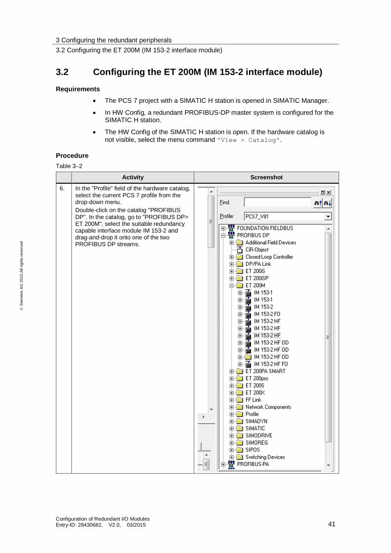
ProcedureTable 3–2
Activity Screenshot
6. In the "Profile" field of the hardware catalog,select the current PCS 7 profile from thedrop-down menu.Double-click on the catalog "PROFIBUSDP". In the catalog, go to "PROFIBUS DP>ET 200M", select the suitable redundancycapable interface module IM 153-2 anddrag-and-drop it onto one of the twoPROFIBUS DP streams.

3 Configuring the redundant peripherals3.3 Configuring the signal modules
Configuration of Redundant I/O ModulesEntry-ID: 28430682, V2.0, 03/2015 42
Sie
men
sA
G20
15A
llrig
hts
rese
rved
Activity Screenshot
7. Enter the address in the dialog box"PROFIBUS IM 153-2 Interface Properties"and click "OK".The connection to the redundantPROFIBUS DP stream is automaticallyestablished.
3.3 Configuring the signal modules
The following section explains the procedure for configuring the standard andHART signal modules.
Note For the time being do not add any HART field devices to the HART signalmodules. This sequence will be explained in chapter 3.7.
Requirements The PCS 7 project with an H CPU has been created and is open in SIMATIC
Manager.
A redundant PROFIBUS-DP master system is configured for the SIMATICH station in HW ConFigure
In HW Config, the interface module IM 153-2 is configured for the ET 200Mat the redundant PROFIBUS DP.

3 Configuring the redundant peripherals3.3 Configuring the signal modules
Configuration of Redundant I/O ModulesEntry-ID: 28430682, V2.0, 03/2015 43
Sie
men
sA
G20
15A
llrig
hts
rese
rved
ProcedureTable 3–3
Activity Screenshot
1. Select the configured IM 153-2. The moduleoverview is shown in the lower pane.

3 Configuring the redundant peripherals3.3 Configuring the signal modules
Configuration of Redundant I/O ModulesEntry-ID: 28430682, V2.0, 03/2015 44
Sie
men
sA
G20
15A
llrig
hts
rese
rved
2. In the hardware catalog, under "PROFIBUSDP > ET 200M", select the same interfacemodule, which you have already dragged tothe PROFIBUS DP master system via drag-and-drop.
3. Select a redundancy capable signal modulein the subdirectories and drag-and-drop itinto a free slot of the IM 153-2 (moduleoverview).
3 Configuring the redundant peripherals3.3 Configuring the signal modules
Configuration of Redundant I/O ModulesEntry-ID: 28430682, V2.0, 03/2015 45
Sie
men
sA
G20
15A
llrig
hts
rese
rved
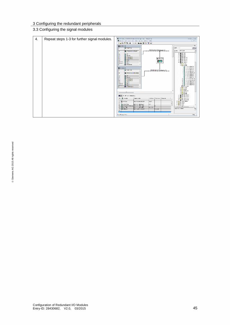
4. Repeat steps 1-3 for further signal modules.

3 Configuring the redundant peripherals3.4 Configuring the second ET 200M
Configuration of Redundant I/O ModulesEntry-ID: 28430682, V2.0, 03/2015 46
Sie
men
sA
G20
15A
llrig
hts
rese
rved
3.4 Configuring the second ET 200M
Once you have configured the first ET 200M with all the necessary components(IM 153-2 interface module, signal modules), you must now configure the secondredundant ET 200M. It should be noted that redundant operation is only possiblewith modules that have the same MLFB. To avoid configuration errors, it istherefore advisable to copy the first ET 200M and paste it in the same mastersystem.
Requirements The PCS 7 project with an H CPU has been created and is open in SIMATIC
Manager.
A redundant PROFIBUS-DP master system is configured for the SIMATICH station in HW ConFigure
In HW Config, the interface module IM 153-2 is configured for the ET 200Mat the redundant PROFIBUS DP.
All required signal modules are configured.
ProcedureTable 3–4
Activity Screenshot
1. Open HW KonFigure Select the alreadyconfigured ET 200M and copy it to theclipboard.

3 Configuring the redundant peripherals3.4 Configuring the second ET 200M
Configuration of Redundant I/O ModulesEntry-ID: 28430682, V2.0, 03/2015 47
Sie
men
sA
G20
15A
llrig
hts
rese
rved
Activity Screenshot
2. Select one of the PROFIBUS DP streamsand paste the copied ET 200M.
3. Allocate the address of the redundant slavein the appearing properties dialog"PROFIBUS Interface IM 153-2" andclick "OK". Make sure that this addressis different from the address of the firstET 200M.

3 Configuring the redundant peripherals3.5 Signal module settings
Configuration of Redundant I/O ModulesEntry-ID: 28430682, V2.0, 03/2015 48
Sie
men
sA
G20
15A
llrig
hts
rese
rved
3.5 Signal module settings
Once you have configured both ET 200M stations, you have to change varioussettings in your standard and HART signal modules.Redundant modules must be in the process image of the inputs or outputs.Redundant modules are always accessed using the process image.
Requirements The PCS 7 project with an H CPU has been created and is open in SIMATIC
Manager.
A redundant PROFIBUS-DP master system is configured for the SIMATICH station in HW ConFigure
In HW Config, the interface module IM 153-2 is configured for the ET 200Mat the redundant PROFIBUS DP.
All required signal modules are configured.
The redundant ET 200M has been configured.
ProcedureTable 3–5
Activity Screenshot
1. Open HW KonFigureSelect once again the firstIM 153-2.Double-click a signal module in the moduleoverview. The dialog box "Properties" ofthis module is opened.
2. Switch to the “Addresses” tab.Select the desired process image partitionfrom the drop-down list "Process image".

3 Configuring the redundant peripherals3.5 Signal module settings
Configuration of Redundant I/O ModulesEntry-ID: 28430682, V2.0, 03/2015 49
Sie
men
sA
G20
15A
llrig
hts
rese
rved
Activity Screenshot
3. Then select the "Redundancy" tab.In the "Redundancy" drop-down list,select the entry "2 modules".
4. Click on the "Find" button. The dialogwindow "Find Redundant Module" opens.
5. In the "Subsystem" list, select the DPmaster system in which the redundantsignal module is configured.All PROFIBUS addresses, available on thisDP master system, are displayed in thefield "PROFIBUS Address".
6. In the field "PROFIBUS Address", selectthe IM 153-2 in which the redundant signalmodule is configured. The redundantmodule field: shows the redundancycapable signal modules available in thisIM 153-2, for which no redundancy hasyet been configured.In the Redundant module field, selectthe signal module which is to be used asa redundant signal module and click the"OK" button.
3 Configuring the redundant peripherals3.5 Signal module settings
Configuration of Redundant I/O ModulesEntry-ID: 28430682, V2.0, 03/2015 50
Sie
men
sA
G20
15A
llrig
hts
rese
rved
Activity Screenshot
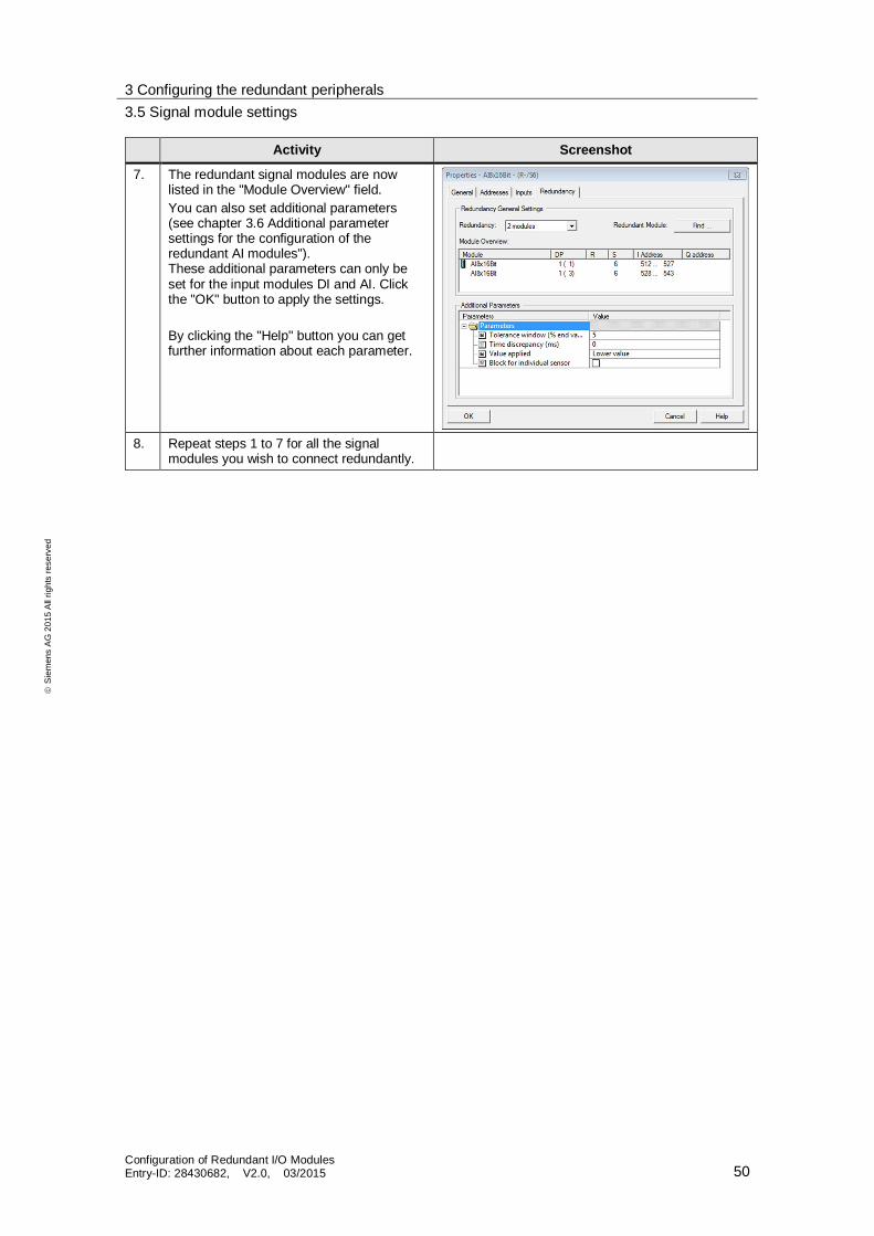
7. The redundant signal modules are nowlisted in the "Module Overview" field.You can also set additional parameters(see chapter 3.6 Additional parametersettings for the configuration of theredundant AI modules").These additional parameters can only beset for the input modules DI and AI. Clickthe "OK" button to apply the settings.
By clicking the "Help" button you can getfurther information about each parameter.
8. Repeat steps 1 to 7 for all the signalmodules you wish to connect redundantly.

3 Configuring the redundant peripherals3.6 Additional parameter settings for the configuration of the redundant AI modules
Configuration of Redundant I/O ModulesEntry-ID: 28430682, V2.0, 03/2015 51
Sie
men
sA
G20
15A
llrig
hts
rese
rved
3.6 Additional parameter settings for the configuration ofthe redundant AI modules
This chapter is intended to assist you in configuring the various parameters thatmust be set for redundant AI modules.To do so, you have to take two main points into account: Special redundancy-related parameters in the HW Config Time or cycle considerations
Figure 3–1
By clicking the "Help" button you can get further information about the followingparameters: Tolerance window
A percentage of the full-scale value of the measuring range is configured.Two analog values are equal if they are within the tolerance window.
Time discrepancyIt is the maximum allowable time in which the redundant input signals can bedifferent.
Value appliedThe "Value applied" is the value of the two analog input values (higher value /lower value), which is transferred to the user program.

3 Configuring the redundant peripherals3.6 Additional parameter settings for the configuration of the redundant AI modules
Configuration of Redundant I/O ModulesEntry-ID: 28430682, V2.0, 03/2015 52
Sie
men
sA
G20
15A
llrig
hts
rese
rved
Discrepancy time / deviation timeAs described in the help for AI modules, the deviation time of AI modules shouldbe a multiple of the update time. To calculate the update time, the followingparameters must be considered: Update time of the AI modules Cycle time of the PROFIBUS (can be ignored if the baud rate is 1.5 Mpps). Update time of the (partial) process images (TPA)
The update time of an analog value for an analog input card, such as 6ES 7331-7TF01, can be taken from the table 3–6.First, select the parameter "Integration time / interference frequency suppression".Then you allocate the number of channels used.
Table 3–6: Analog value for parameters
Analog value conversion
Principle ofmeasurement
SIGMA DELTA
Integration time /interference frequencysuppression (per channel)
60 Hz 50 Hz 10 Hz
Integration time error ± 0.05% ± 0.04% ± 0.02%Integration time in ms 16.6 20 100Basic reaction timeincluding integration time inms (per channel)
55 65 305
Basic module executiontime in ms (all channelsenabled)
440 520 2440
Smoothing the measuredvalue
Step:NoneWeakAverageStrong
Time constant:1 x cycle time ***4 x cycle time ***32 x cycle time ***64 x cycle time ***
Max module cycle:2.44 s9.76 s78.08 s156.16 s
Table 3–7: Examples
Integration time / interference frequencysuppression
Number of channelsused
Update timeof module
50 Hz 1 65 ms50 Hz 4 260 ms50 Hz 8 520 ms10 Hz 1 305 ms10 Hz 4 1220 ms10 Hz 8 2440 ms

3 Configuring the redundant peripherals3.6 Additional parameter settings for the configuration of the redundant AI modules
Configuration of Redundant I/O ModulesEntry-ID: 28430682, V2.0, 03/2015 53
Sie
men
sA
G20
15A
llrig
hts
rese
rved
To obtain the update time of the (partial) process image (TPA), in the first step,the assigned (partial) process image of the AI module in question must be found,as shown in this picture.Figure 3–2
In the second step, the cycle time is determined in the properties of the CPU.In this example, the update time of the (partial) process image (TPA) is 500msfor the used TPA 3Figure 3–3
Calculation of total deviation time:
Time deviation = 2 * (time module + time TPA)

3 Configuring the redundant peripherals3.6 Additional parameter settings for the configuration of the redundant AI modules
Configuration of Redundant I/O ModulesEntry-ID: 28430682, V2.0, 03/2015 54
Sie
men
sA
G20
15A
llrig
hts
rese
rved
The factor 2 is the smallest factor that may be used. If the process conditions allowa higher value, the factor can also be 3 or 4.
Table 3–8. Examples
Parameter Discrepancy time to be set
50 Hz, 1 channel, TPA = 500 ms 1130 ms50 Hz, 4 channels, TPA = 500 ms 1520 ms50 Hz, 8 channels, TPA = 500 ms 2040 ms10 Hz, 8 channels, TPA = 50 ms 5880 ms
Note In the event that two different integration times are assigned to the channels ofa module (10 Hz and 50 Hz), the worst case is calculated. This means that thecalculation is performed with 10 Hz.
Tolerance windowDepending on the quality of the field signal, a tolerance range of 5% to 20% shouldbe set.
General time or cycle assessmentThe redundant modules may only be accessed via the process image.For more information on how to configure the I/O modules, please refer tochapter 3.5 "Signal module settings".The same process image partition must be assigned to both modules ofa redundant pair.The relevant channel blocks should either have the same cycle time as the processimage process image partition or have their cycle slowed down. No advantageis gained from being faster than the process image partition.

3 Configuring the redundant peripherals3.7 Configuring the HART field devices
Configuration of Redundant I/O ModulesEntry-ID: 28430682, V2.0, 03/2015 55
Sie
men
sA
G20
15A
llrig
hts
rese
rved
3.7 Configuring the HART field devices
Requirements The PCS 7 project with an H CPU has been created and is open in SIMATIC
Manager.
A redundant PROFIBUS-DP master system is configured for the SIMATICH station in HW ConFigure
In HW Config, the interface module IM 153-2 is configured for the ET 200Mat the redundant PROFIBUS DP.
All required signal modules are configured.
The redundant ET 200M has been configured.
The settings on the signal module have been done
ProcedureTable 3–9
Activity Screenshot
1. Open HW ConFigureSelect the HART field device in thehardware catalog and drag-and-drop it intoa free slot of the HART module in themodule overview.
2. Double-click the HART field device. In theappearing dialog box, select the appropriatedevice and click "OK".

3 Configuring the redundant peripherals3.8 Symbolic name assignment
Configuration of Redundant I/O ModulesEntry-ID: 28430682, V2.0, 03/2015 56
Sie
men
sA
G20
15A
llrig
hts
rese
rved
Activity Screenshot
3. The HART field device is opened inSIMATIC PDM. Here you can adjust otherdevice parameters (such as TAG).
4. Select again the HART field device in thehardware catalog and drag-and-drop it intoa free slot of the redundant partner (HARTsignal module of the second ET 200M).After a brief loading, the configured fielddevice of the first ET 200M is automaticallyassigned.
3.8 Symbolic name assignment
For the symbolic name assignment it is assumed that the input/output moduleshave been already added in the HW ConFigure Once this is done, you can assignself-explanatory symbolic names to the inputs and outputs of these modules.You use these names to connect CFC charts with the input and output modules.
Requirements The PCS 7 project with an H CPU has been created and is open in SIMATIC
Manager. A redundant PROFIBUS-DP master system is configured for the SIMATIC
H station in HW ConFigure In HW Config, the interface module IM 153-2 is configured for the ET 200M
at the redundant PROFIBUS DP. All required signal modules are configured. The redundant ET 200M has been configured. The settings on the signal module have been done
3 Configuring the redundant peripherals3.8 Symbolic name assignment
Configuration of Redundant I/O ModulesEntry-ID: 28430682, V2.0, 03/2015 57
Sie
men
sA
G20
15A
llrig
hts
rese
rved
ProcedureTable 3–10
Activity Screenshot
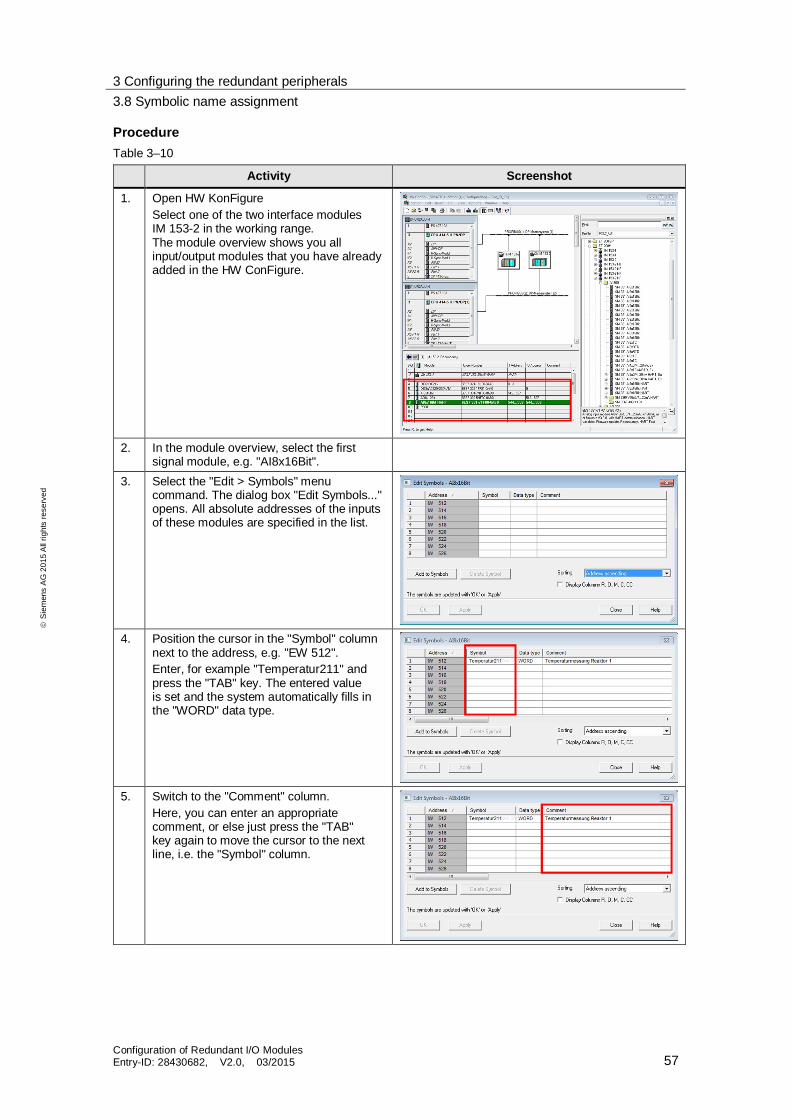
1. Open HW KonFigureSelect one of the two interface modulesIM 153-2 in the working range.The module overview shows you allinput/output modules that you have alreadyadded in the HW ConFigure.
2. In the module overview, select the firstsignal module, e.g. "AI8x16Bit".
3. Select the "Edit > Symbols" menucommand. The dialog box "Edit Symbols..."opens. All absolute addresses of the inputsof these modules are specified in the list.
4. Position the cursor in the "Symbol" columnnext to the address, e.g. "EW 512".Enter, for example "Temperatur211" andpress the "TAB" key. The entered valueis set and the system automatically fills inthe "WORD" data type.
5. Switch to the "Comment" column.Here, you can enter an appropriatecomment, or else just press the "TAB"key again to move the cursor to the nextline, i.e. the "Symbol" column.

3 Configuring the redundant peripherals3.9 CFC configuration
Configuration of Redundant I/O ModulesEntry-ID: 28430682, V2.0, 03/2015 58
Sie
men
sA
G20
15A
llrig
hts
rese
rved
Activity Screenshot
6. If necessary, edit additional symbolsand save your entries by clicking the"OK" button.The dialog box "Edit Symbols" is closed.
7. Select each signal module, one after theother, in the module overview and assignthem symbolic names. To do this, follow thesteps 2 to 6.
3.9 CFC configuration
Once you have completed the necessary configurations, you have to createCFC charts. In this step you connect the input/output modules you added in theHW Config with the corresponding channel blocks.
Requirements All the required I/O modules have been configured in the HW Config and
the associated symbols have been assigned. The CFC chart has been created and is open.
ProcedureTable 3–11
Activity Screenshot
1. Select the "Libraries" tab In the lower leftpane. Select the path "PCS 7 AP LibraryV81 > Blocks+Templates\Blocks >Channel".Now drag the driver module Pcs7AnIn,Pcs7AnOu, Pcs7DiIn or Pcs7DiOu anddrop it into your plan, depending on theinput/output module.
2. To connect further building blocks, dragthem into your plan. For example, if youwant to measure temperature, you canconnect the channel block with a MonAnSor MonAnL, which allow the measuredtemperature to be displayed later on duringoperation.
3. To connect the channel module with itsconfigured I/O module, select the block,click on "PV_In" of the channel block andopen the menu command "Insert >Connection to Address".The symbol table opens.
3 Configuring the redundant peripherals3.9 CFC configuration
Configuration of Redundant I/O ModulesEntry-ID: 28430682, V2.0, 03/2015 59
Sie
men
sA
G20
15A
llrig
hts
rese
rved
Activity Screenshot
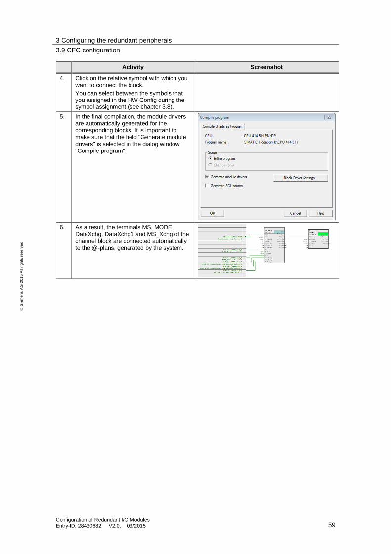
4. Click on the relative symbol with which youwant to connect the block.You can select between the symbols thatyou assigned in the HW Config during thesymbol assignment (see chapter 3.8).
5. In the final compilation, the module driversare automatically generated for thecorresponding blocks. It is important tomake sure that the field "Generate moduledrivers" is selected in the dialog window"Compile program".
6. As a result, the terminals MS, MODE,DataXchg, DataXchg1 and MS_Xchg of thechannel block are connected automaticallyto the @-plans, generated by the system.
4 Function mechanisms4.1 Example of a flowchart
Configuration of Redundant I/O ModulesEntry-ID: 28430682, V2.0, 03/2015 60
Sie
men
sA
G20
15A
llrig
hts
rese
rved
4 Function mechanisms4.1 Example of a flowchart
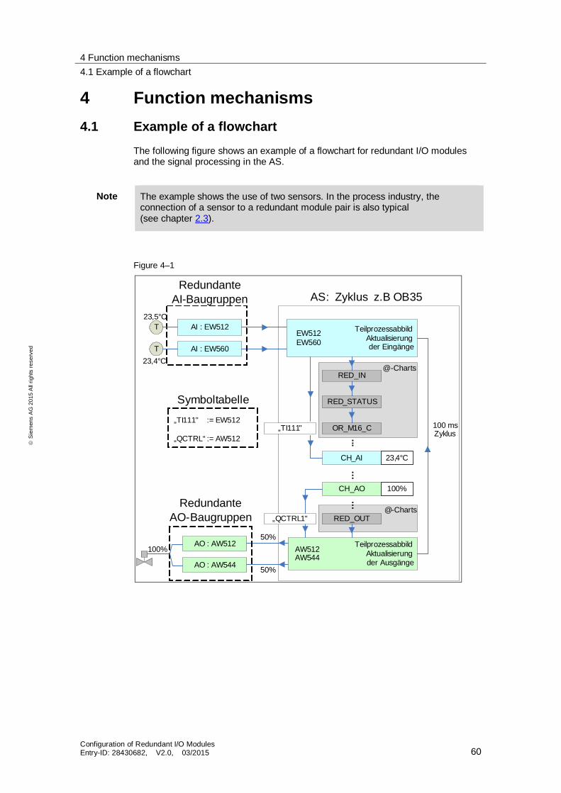
The following figure shows an example of a flowchart for redundant I/O modulesand the signal processing in the AS.
Note The example shows the use of two sensors. In the process industry, theconnection of a sensor to a redundant module pair is also typical(see chapter 2.3).
Figure 4–1
TeilprozessabbildAktualisierungder Eingänge
AI : EW512
AI : EW560
AS: Zyklus z.B OB35
CH_AO
RedundanteAI-Baugruppen
......
...
AO : AW512
AO : AW544
CH_AI
100 msZyklus
RED_IN
RED_STATUS
OR_M16_C
RED_OUT
„TI111"
„QCTRL1"
TeilprozessabbildAktualisierungder Ausgänge
EW512EW560
AW512AW544
RedundanteAO-Baugruppen
@-Charts
@-Charts
Symboltabelle
„TI111" := EW512
„QCTRL“ := AW512
T
T
23,5°C
23,4°C
23,4°C
100%
50%
50%
100%

4 Function mechanisms4.1 Example of a flowchart
Configuration of Redundant I/O ModulesEntry-ID: 28430682, V2.0, 03/2015 61
Sie
men
sA
G20
15A
llrig
hts
rese
rved
Description of the upper part of the flowchartIn the upper part, two temperature measurements are transferred by two encodersvia two redundant AI modules and written via two addresses (EW512, EW560) inthe process image partition of the inputs.Depending on the setting of the transfer value (see Additional ParametersTable 3–5 point 7), the smaller or greater value is written in the user program onthe channel block CH_AI via the corresponding "TI111" symbol.The @-charts, where the blocks from the redundant IO CGP (RED_IN,RED_STATUS, etc.) and from the PCS 7 Library (OR_M16_C) are placed, allowthe diagnostic and redundancy analysis to be performed. The block OR_M16_Ctransmits the corresponding diagnostic or redundancy status to the channel blockCH_AI.This automatically leads to the corresponding redundancy message behavior,depending on the status (OR_M16_C, see below).
Description of the lower part of the flowchartIn the lower part of the flowchart, a control valve is controlled by two redundantanalog output modules.
Note Only analog output modules with current outputs can be operated redundantly(0…20mA, 4…20mA). See chapter 2.3.4 "Analog output".
A value is written into the process image partition of the outputs from the channelblock CH_AO via the pre-configured symbol "QCTRL1". The @-charts andespecially the RED_OUT allow information to be analyzed and correspondingoutput values to be given out by the system. This is done via the process imagepartition of the outputs (addresses AW512 and AW544).The value to be transferred is halved and each of the two channels transmits halfthe value. If one of the channels or modules fails, this is detected and theremaining channel or module transmits the full value.This flowchart is repeated cyclically according to call and cycle time of the OBsused (in this case OB35 every 100 ms).

4 Function mechanisms4.2 Library functions
Configuration of Redundant I/O ModulesEntry-ID: 28430682, V2.0, 03/2015 62
Sie
men
sA
G20
15A
llrig
hts
rese
rved
4.2 Library functions
The following section describes the blocks/functions used from the PCS 7 and theRedundant IO CGP libraries.
4.2.1 PCS 7 Basic Library V8.1
OR_M_16CThe block OR_M_16C serves to form a channel-granular value status from tworedundant signal modules.
MOD-D1The module MOD_1 monitors a max of16-channel S7-300/400 SM modules which have no diagnostics capabilities(no mixed modules).In H systems, only modules in switched racks are supported.
4.2.2 Redundant IO CGP V5.2
RED_INThe FB 450 ensures reading of the signal from the redundant input peripherals(DI, AI), which is assigned to the process image partition in the priority class of thecalling OB.The FB 450 performs a discrepancy analysis of the redundant input peripheralsand saves the valid value to the lower address in the process image inputs (PII).The user can only access his application this way. The PII of the high module isirrelevant.
RED_STATUSThe FB 453 "RED_STATUS" represents an interface block and containsinformation regarding the passivation of modules.
RED_OUTThe FB 451 transmits those redundant peripheral signals that are assigned tothe process image partition in the priority class of the calling OB.
RED_DIAGThe FB 452 RED_DIAG evaluates the start information of individual fault anddiagnostic OBs to refer to a corresponding processing sequence.It is called up in the acyclic OBs (e.g. OB 82, OB 85).
RED_DEPAThis function starts a depassivation by the user program.The FC checks whether a redundant module or channel is passivated. If a moduleor channel is passivated, a complete depassivation is started in the FB 450"RED_IN". In the opposite case (no passivation of a module or a channel present),the processing of the FC 451 is terminated immediately.The function is called up in the acyclic OBs (e.g. OB 82, OB 85).

4 Function mechanisms4.3 OS messages of the modules
Configuration of Redundant I/O ModulesEntry-ID: 28430682, V2.0, 03/2015 63
Sie
men
sA
G20
15A
llrig
hts
rese
rved
RED_INITWith the FC 450 "RED_INIT", the peripheral redundancy is initialized in the startupof an H system.When the FC 450 is called up, it generates administration data blocks for functionalperipheral redundancy and it either occupies it with default values or else itupdates pre-existing administration DBs. The function triggers a completedepassivation, which is then executed in FB 450 "RED_IN".The function is called up in the acyclic OBs (e.g. OB 82, OB 85).
4.3 OS messages of the modules
When compiling the OS, the following module messages are created in the OS.
Redundancy reporting behavior (OR_M_16C) BG x/y/z: Failure of module redundancy pair
BG x/y/z: Module redundancy loss
BG x/y/z: Module status cannot be determined
BG x/y/z: Discrepancy time has expired
BG x/y/z: Failure of redundancy pair channel xx
Table 4-1
Letter Description
X DP master system no.Y DP slave addressZ Slot no.XX Channel no.

4 Function mechanisms4.3 OS messages of the modules
Configuration of Redundant I/O ModulesEntry-ID: 28430682, V2.0, 03/2015 64
Sie
men
sA
G20
15A
llrig
hts
rese
rved
Reporting behavior of a module with diagnostic capability (MOD_D1) Possible module fault (output parameter QMODF = TRUE):
– External auxiliary voltage missing– Front connector missing– Module parameters not set– incorrect parameters in module– Missing/wrong module– CPU communication fault– Time monitoring activated (watchdog)– Module internal supply voltage failure– Rack failure– Processor failure– EPROM error– RAM error– ADC/DAC error– Fuse blown– Power supply 1: Fault– Power supply 2: Fault
Possible channel fault ("invalid value" value status, OMODE_xx = 16#00xxxx):– Configuration/parameter assignment error– Common mode error, only analog input/output– I/O short circuit– Short-circuit to M– Output transistor is interrupted– Wire break– Reference channel fault (only analog input)– Below measuring range (only analog input)– Above measuring range (only analog input)– Missing load voltage (only analog and digital output)– Missing encoder power supply (only digital output)– Fuse blown (only digital output)– Grounding fault (only digital input/output)– Temperature rise (only digital output)

5 Diagnostics5.1 Failure scenario
Configuration of Redundant I/O ModulesEntry-ID: 28430682, V2.0, 03/2015 65
Sie
men
sA
G20
15A
llrig
hts
rese
rved
5 DiagnosticsThis chapter presents an example of the diagnostic possibilities with PCS 7 interms of redundant peripherals.
5.1 Failure scenario
A channel fault due to a wire break is simulated on a digital input module with therunning system.Figure 5-1
It should be noted that the components used in the example are channel-granular.A wire break at a terminal of the digital input module results in the passivation ofthe faulty channel (or channel group) only and not the entire module. The occurredfault can be diagnosed in the following ways: OS messages Asset management HW Config CFC test mode
In the practical environment, the fault is first seen by the plant operator on the OSin the control room. Then, the maintenance engineer will have a look at theappropriate message list.At the same time, the Asset Management gives him further information about thecondition of the signal module. Thanks to a button, Asset Management providesthe possibility of opening the HW Config to receive further diagnostics entries inthe module status of the H CPU and the signal module.At the same time, other status values of the signal module are available in theCFC test mode.

5 Diagnostics5.2 OS messages
Configuration of Redundant I/O ModulesEntry-ID: 28430682, V2.0, 03/2015 66
Sie
men
sA
G20
15A
llrig
hts
rese
rved
5.2 OS messages
In the OS, you receive corresponding error messages via the button "New List".Figure 5–2
5 Diagnostics5.3 Asset management
Configuration of Redundant I/O ModulesEntry-ID: 28430682, V2.0, 03/2015 67
Sie
men
sA
G20
15A
llrig
hts
rese
rved
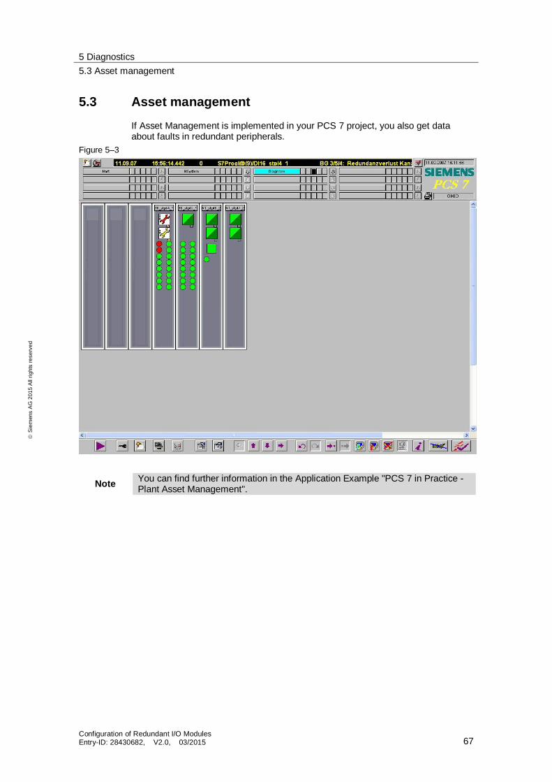
5.3 Asset management
If Asset Management is implemented in your PCS 7 project, you also get dataabout faults in redundant peripherals.
Figure 5–3
Note You can find further information in the Application Example "PCS 7 in Practice -Plant Asset Management".

5 Diagnostics5.4 HW Config Online
Configuration of Redundant I/O ModulesEntry-ID: 28430682, V2.0, 03/2015 68
Sie
men
sA
G20
15A
llrig
hts
rese
rved
5.4 HW Config Online
Diagnostics bufferIn the online mode of the HW Config, you can see the event information shownFigure 5-4, under the "Diagnostic Buffer" tab inside the "Module State" of theH CPU. In addition to fault messages, even information about the behavior of themodules is listed here.The wire break is listed here in the "Events" field via the numbers 20 to 23.By highlighting the corresponding message, further information is displayed inthe "Event details" field.Figure 5-4

5 Diagnostics5.4 HW Config Online
Configuration of Redundant I/O ModulesEntry-ID: 28430682, V2.0, 03/2015 69
Sie
men
sA
G20
15A
llrig
hts
rese
rved
Diagnostic interruptThe "Module state" of the signal module (Figure 5-5) is another diagnosticpossibility in HW ConFigure In the "Diagnostic Interrupt" tab you can find the"Standard module diagnostics" and the "Channel-specific diagnostics".Figure 5-5
By clicking on the "Show" button you receive further information about the selecteddiagnostic line.

5 Diagnostics5.5 CFC test mode
Configuration of Redundant I/O ModulesEntry-ID: 28430682, V2.0, 03/2015 70
Sie
men
sA
G20
15A
llrig
hts
rese
rved
5.5 CFC test mode
The OR_M_16C enables the value status of the redundant signal modules to bediagnosed (Figure 5–6) in the CFC chart.Here, the different connections of the module can be registered in test mode.Figure 5–6
From the outputs QMODF1 and QMODF2, you can see that there is no modulefault. From the inputs ACTIV_L or ACTIV _H, you can see whether one of the twomodules is active or passive.The wire break at the connection MODE1_00 with status 16#FFFF gives an invalidvalue.The MODE1_00 connection shows the status for channel 0 of the primary digitalinput module.The MODE2_00 connection shows the status for channel 0 of the secondredundant digital input module. The 16#8000FFFF at connection MODE2_00 isa valid value.

5 Diagnostics5.5 CFC test mode
Configuration of Redundant I/O ModulesEntry-ID: 28430682, V2.0, 03/2015 71
Sie
men
sA
G20
15A
llrig
hts
rese
rved
The following table shows further connection properties of the OR_M_16C:Table 5–1
Connection Meaning Data Type DefaultSetting
Type
MODE1_xx Channel operating mode (xx = 00 – 07 / 00 – 15)of the primary module
DWORD 0 I
MODE2_xx Channel operating mode (xx = 00 – 07 / 00 – 15)of the redundant module
DWORD 0 I
OMODE_xx Channel operating mode (xx = 00 – 07 / 00 – 15) DWORD 0 OQDISCREP 1 = expired discrepancy time BOOL 0 OQMODF1 1 = error in module 1 BOOL 0 OQMODF2 1 = error in module 2 BOOL 0 O
Note Further information about the connections of the OR_M_16 and its faultmessages can be found in the manual "SIMATIC Process Control System PCS 7Basic Library (V8.1)".
Examples of the value status Byte 3:
– 16#80: Value status "valid value"– 16#00: Value status "invalid value" (channel fault)– 16#40: Value status "invalid value" (higher-level fault)
Byte 2:– 16#01: Restart (OB 100) done
– 16#02: Above measuring range (channel fault diagnostics)
– 16#04: Below measuring range (channel fault diagnostics)

6 Related literature
Configuration of Redundant I/O ModulesEntry-ID: 28430682, V2.0, 03/2015 72
Sie
men
sA
G20
15A
llrig
hts
rese
rved
6 Related literature
Table 6-1
Topic Title / Link
\1\ Siemens Industry Online Support http://support.industry.siemens.com
\2\ Download page of this entry https://support.industry.siemens.com/cs/ww/en/view/28430682
\3\ SIMATIC Process Control System -PCS 7 High-availability ProcessControl Systems (V8.1)
https://support.industry.siemens.com/cs/ww/en/view/90682535
\4\ SIMATIC PCS 7 process controlsystem CPU 410-5H ProcessAutomation
https://support.industry.siemens.com/cs/ww/en/view/74736822
\5\ SIMATIC Process Control SystemPCS 7 Basic Library (V8.1)
https://support.industry.siemens.com/cs/ww/en/view/90683135
7 History
Table 7-1
Version Date Modifications
V1.0 02/2008 First versionV1.1 04/2010 Figure 2-6 correctedV1.2 10/2013 New chapter: 3.6 "Additional parameter settings for the
configuration of the redundant AI modules"V2.0 03/2015 Revision for PCS 7 V8.1