Application Considerations and License …Converged Access branch design, and a Centralized campus...
46
CHAPTER 7-1 Cisco Bring Your Own Device (BYOD) CVD 7 Application Considerations and License Requirements for BYOD Revised: March 6, 2014 What’s New: The Quality of Service (QoS) section has been re-written to add a QoS discussion around Converged Access products, including the Catalyst 3850 Series switch and the Cisco 5760 wireless LAN controller. When implementing a BYOD solution, the applications that run on employee-owned devices need to be considered before selecting which of the particular BYOD use cases discussed above to deploy. The application requirements for these devices determine the level of network connectivity needed. The network connectivity requirements in turn influence the choice of the BYOD use case to apply. Quality of Service In addition to network connectivity, Quality of Service (QoS) is an important consideration for applications, especially those delivering real-time media. Device specific hardware, such as dedicated IP phones which send only voice traffic, allowed for the configuration of dedicated voice wireless networks. However, with the widespread use of smartphones and tablets which support collaboration software (such as Cisco’s Jabber client), devices are capable of sending voice, video, and data traffic simultaneously. Hence, QoS is necessary to provide the necessary per-hop behavior as such traffic traverses the network infrastructure. QoS can be categorized into the following broad functions: • Classification and Marking-including Application Visibility and Control (AVC) • Bandwidth Allocation/Rate Limiting (Shaping and/or Policing) • Trust Boundary Establishment • Queueing For a discussion regarding implementing wired QoS, refer to Medianet Campus QoS Design 4.0 at: http://www.cisco.com/en/US/docs/solutions/Enterprise/WAN_and_MAN/QoS_SRND_40/QoSCampus _40.html. The solution presented within this document supports two different types of WLAN QoS—traditional “precious metals” QoS implemented by CUWN wireless LAN controller platforms and Converged Access QoS implemented by IOS XE based wireless LAN controller platforms. The following sections discuss various aspects of wireless QoS for each of the respective platforms.
Transcript of Application Considerations and License …Converged Access branch design, and a Centralized campus...

C H A P T E R 7
Application Considerations and License Requirements for BYODRevised: March 6, 2014
What’s New: The Quality of Service (QoS) section has been re-written to add a QoS discussion around Converged Access products, including the Catalyst 3850 Series switch and the Cisco 5760 wireless LAN controller.
When implementing a BYOD solution, the applications that run on employee-owned devices need to be considered before selecting which of the particular BYOD use cases discussed above to deploy. The application requirements for these devices determine the level of network connectivity needed. The network connectivity requirements in turn influence the choice of the BYOD use case to apply.
Quality of ServiceIn addition to network connectivity, Quality of Service (QoS) is an important consideration for applications, especially those delivering real-time media. Device specific hardware, such as dedicated IP phones which send only voice traffic, allowed for the configuration of dedicated voice wireless networks. However, with the widespread use of smartphones and tablets which support collaboration software (such as Cisco’s Jabber client), devices are capable of sending voice, video, and data traffic simultaneously. Hence, QoS is necessary to provide the necessary per-hop behavior as such traffic traverses the network infrastructure.
QoS can be categorized into the following broad functions:
• Classification and Marking-including Application Visibility and Control (AVC)
• Bandwidth Allocation/Rate Limiting (Shaping and/or Policing)
• Trust Boundary Establishment
• Queueing
For a discussion regarding implementing wired QoS, refer to Medianet Campus QoS Design 4.0 at: http://www.cisco.com/en/US/docs/solutions/Enterprise/WAN_and_MAN/QoS_SRND_40/QoSCampus_40.html.
The solution presented within this document supports two different types of WLAN QoS—traditional “precious metals” QoS implemented by CUWN wireless LAN controller platforms and Converged Access QoS implemented by IOS XE based wireless LAN controller platforms. The following sections discuss various aspects of wireless QoS for each of the respective platforms.
7-1Cisco Bring Your Own Device (BYOD) CVD
Chapter 7 Application Considerations and License Requirements for BYODQuality of Service
CUWN Wireless LAN Controller QoSAs of Cisco Unified Wireless Network (CUWN) software release 7.3 and above, wireless QoS is configured by applying one of four “precious metals” QoS Profiles—Platinum, Gold, Silver, or Bronze—to the WLAN to which a particular client device is associated. An example of the configuration is shown in Figure 7-1.
Figure 7-1 Application of a QoS Profile to a WLAN
Note that the QoS settings for the profile can be overridden on a per-WLAN basis from within the QoS tab of the WLAN configuration.
The DSCP marking of client traffic, as it traverses the network within a CAPWAP tunnel, is controlled by three fields within the WLAN QoS Parameters field within the QoS Profile:
• Maximum Priority—This is the maximum 802.11 User Priority (UP) value of a packet sent by a Wi-Fi Multimedia (WMM)-enabled client which will be allowed by the access point. The User Priority maps to a DSCP value within the outer header of the CAPWAP tunnel as the packet traverses the network infrastructure. If the WMM-enabled client sends an 802.11 packet with a User Priority higher than allowed, the access point marks the packet down to the maximum allowed User Priority. This in turn maps to the DSCP value of the external CAPWAP header as the packet is sent over the network infrastructure.
• Unicast Default Priority—This is the default 802.11 User Priority (UP) to which a unicast packet sent by a non-WMM-enabled client is assigned. This User Priority also maps to the DSCP value within the outer header of the CAPWAP tunnel as the packet traverses the network infrastructure.
7-2Cisco Bring Your Own Device (BYOD) CVD

Chapter 7 Application Considerations and License Requirements for BYODQuality of Service
• Multicast Default Priority—This is the default 802.11 User Priority (UP) for multicast traffic. This User Priority maps to a DSCP value within the outer header of the CAPWAP tunnel as the packet traverses the network infrastructure.
Table 7-1 shows the default WLAN QoS parameter settings in terms of 802.11 access category designation and corresponding mapped DSCP value.
An example of the configuration of the WLAN QoS Parameters is shown in Figure 7-2.
Figure 7-2 Controlling the Marking of Wireless Packets
It should be noted that these settings apply primarily to Local Mode (centralized wireless controller) designs and FlexConnect designs with central termination of traffic, since the WLAN QoS Parameters field results in the mapping of the 802.11 User Priority to the DSCP value within the outer header of the CAPWAP tunnel.
Table 7-1 Default WLAN QoS Parameter Settings for CUWN Controllers
QoS Profile NameMaximum Priority, Unicast Default Priority, and Multicast Default Priority (802.11 UP) DSCP Mapping
Platinum Voice EF (DSCP 46)
Gold Video AF41 (DSCP 34)
Silver Best Effort Default (DSCP 0)
Bronze Background AF11 (DSCP 10)
7-3Cisco Bring Your Own Device (BYOD) CVD
Chapter 7 Application Considerations and License Requirements for BYODQuality of Service
The original DSCP marking of the packet sent by the wireless client is always preserved and applied as the packet is placed onto the Ethernet segment, whether that is at the wireless controller for centralized wireless controller designs or at the access point for FlexConnect designs with local termination.
The wireless trust boundary is established via the configuration of the WMM Policy within the QoS tab of the WLAN configuration. An example was shown in Figure 7-1. The three possible settings for WMM Policy are:
• Disabled—The access point will not allow the use of QoS headers within 802.11 packets from WMM-enabled wireless clients on the WLAN.
• Allowed—The access point will allow the use of QoS headers within 802.11 packets from wireless clients on the WLAN. However the access point will still allow non-WMM wireless clients (which do not include QoS headers) to associate to the access point for that particular WLAN.
• Required—The access point requires the use of QoS headers within 802.11 packets from wireless clients on the WLAN. Hence, any non-WMM-enabled clients (which do not include QoS headers) will not be allowed to associate to the access point for that particular WLAN.
Note Where possible, it is advisable to configure WMM policy to Required. Some mobile devices may incorrectly mark traffic from collaboration applications when the WMM policy is set to Allowed versus Required. Note however that this requires all devices on the WLAN to support WMM before being allowed onto the WLAN. Before changing the WMM policy to Required, the network administrator should verify that all devices which utilize the WLAN are WMM-enabled. Otherwise, non-WMM-enabled devices will not be able to access the WLAN.
The configuration of the WMM Policy, along with the WLAN QoS Parameters, together create the wireless QoS trust boundary and determine the marking of wireless traffic within the CAPWAP tunnel as it traverses the network infrastructure.
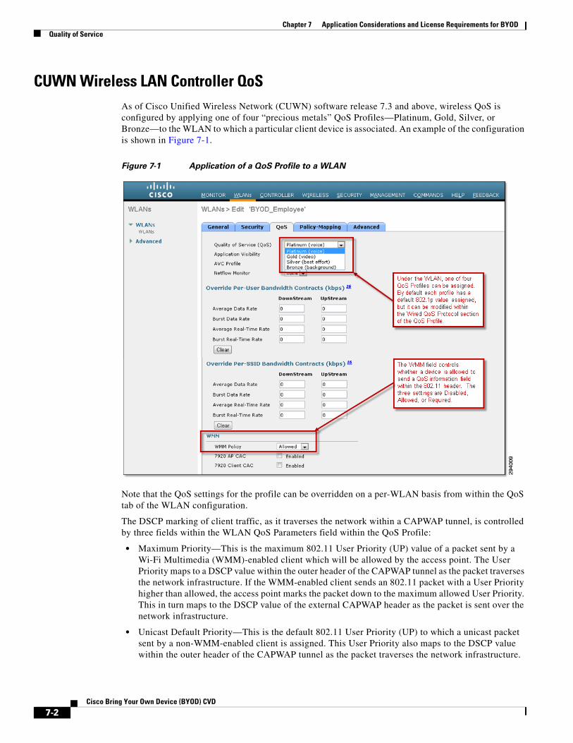
Table 7-2 shows the mapping of the WLANs/SSIDs shown in the BYOD design guide to QoS Profiles within CUWN wireless LAN controllers.
It is assumed that the Employee and Personal Devices SSIDs will need to support wireless clients which run voice, video, and data applications. Hence these SSIDs are configured for the Platinum QoS profile. The Guest, Provisioning, and IT Devices SSIDs are assumed to only require data applications which require a best effort service. However, the business requirements of any organization ultimately determine what devices and applications are supported over the various SSIDs. The design shown in Table 7-2 can easily be modified to reflect the needs of a particular deployment.
Table 7-2 Mapping of BYOD WLANs/SSIDs to QoS Profiles
SSID WLAN/SSID Name QoS Profile
Employee SSID BYOD_Employee Platinum
Personal Devices SSID BYOD_Personal_Device Platinum
Guest SSID BYOD_Guest Silver
Provisioning SSID BYOD_Provisioning Silver
IT Devices SSID IT_Devices Silver
7-4Cisco Bring Your Own Device (BYOD) CVD
Chapter 7 Application Considerations and License Requirements for BYODQuality of Service
Rate Limiting on CUWN Wireless ControllersOne additional option to prevent the wireless medium from becoming saturated, causing excessive latency and loss of traffic, is rate limiting. Rate limiting may be implemented per device or per SSID to prevent individual devices from using too much bandwidth and negatively impacting other devices and applications. Rate limiting on CUWN wireless LAN controllers can be particularly useful for guest access implementations and is discussed in detail in Chapter 21, “BYOD Guest Wireless Access.”
Converged Access QoSThe CT5760 wireless controller and the Catalyst 3850 Series switches both run Cisco IOS XE software. QoS configuration for Converged Access products uses the Modular QoS based CLI (MQC), which is in alignment with other platforms such as Catalyst 4500E Series switches. The Converged Access QoS design presented in this section discusses the ability to provide the following QoS capabilities to Converged Access wireless designs discussed within this document:
• Egress queuing for wireless Catalyst 3850 switch ports, wired Catalyst 3850 uplink ports, and Cisco CT5760 distribution system ports at the port-level policy.
• Downstream bandwidth management at the SSID-level policy.
• Upstream classification and marking at the client-level policy. Optional upstream policing at the client-level policy for Catalyst 3850 Series switches is also discussed.
• Marking of mobility traffic.
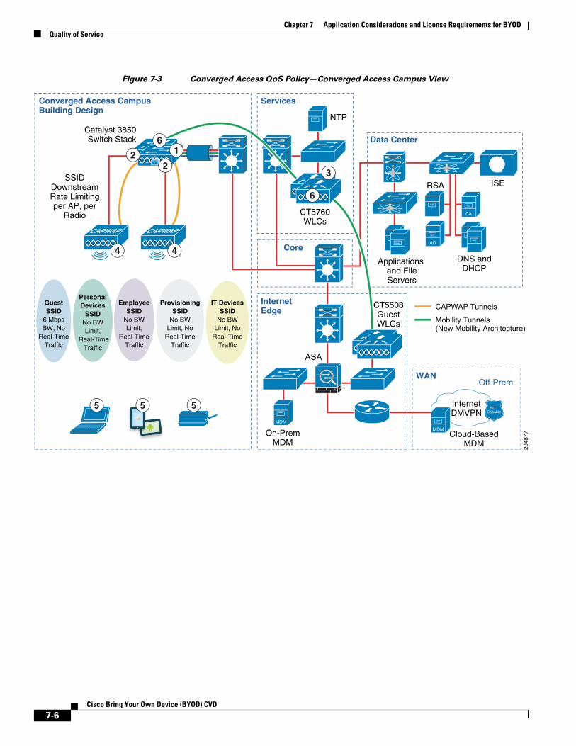
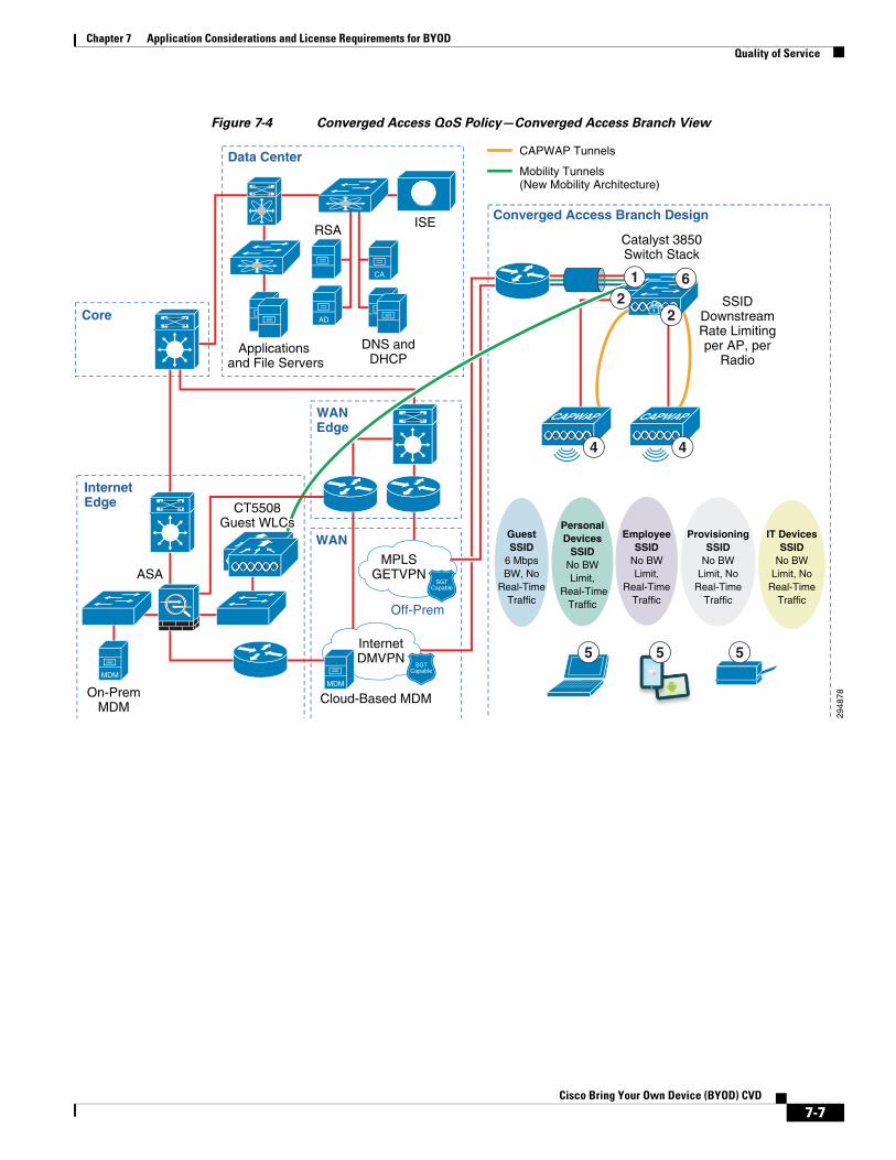
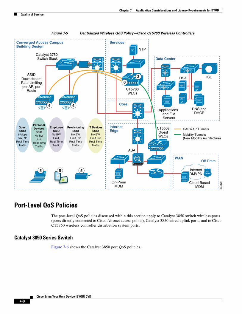
QoS policies discussed within this section will be applied for a Converged Access campus design, a Converged Access branch design, and a Centralized campus design using a Cisco CT5760 wireless controller.
Figure 7-3, Figure 7-4, and Figure 7-5 provide a high-level overview of where QoS policies will be applied to each of the designs. Each of the circled policies is discussed in subsequent sections.
7-5Cisco Bring Your Own Device (BYOD) CVD
Chapter 7 Application Considerations and License Requirements for BYODQuality of Service
Figure 7-3 Converged Access QoS Policy—Converged Access Campus View
2948
77
ASA
Converged Access Campus Building Design
Core
RSA
Applications and FileServers
Catalyst 3850Switch Stack
SSIDDownstreamRate Limitingper AP, per
Radio
Data Center
InternetDMVPN
NTP
CT5760WLCs
Services
InternetEdge
WAN
ISE
DNS andDHCP
On-PremMDM
Off-Prem
AD
MDM
Cloud-BasedMDM
CA
CAPWAP Tunnels
Mobility Tunnels(New Mobility Architecture)
CAPWAP CAPWAP
CT5508GuestWLCs
MDM
4
5 5 5
4
3
6
SGTCapable
16
22
GuestSSID
6 MbpsBW, No
Real-TimeTraffic
PersonalDevices
SSIDNo BWLimit,
Real-TimeTraffic
EmployeeSSID
No BWLimit,
Real-TimeTraffic
ProvisioningSSID
No BWLimit, No
Real-TimeTraffic
IT DevicesSSID
No BWLimit, No
Real-TimeTraffic
7-6Cisco Bring Your Own Device (BYOD) CVD
Chapter 7 Application Considerations and License Requirements for BYODQuality of Service
Figure 7-4 Converged Access QoS Policy—Converged Access Branch View
2948
78
WAN
Off-Prem
Cloud-Based MDM
Core
RSA
Data Center
ISE
DNS andDHCP
AD
CA
Converged Access Branch Design
ASA
InternetEdge
On-PremMDM
MDM
MPLSGETVPN
InternetDMVPN
MDM
Applications and File Servers
GuestSSID
6 MbpsBW, No
Real-TimeTraffic
PersonalDevices
SSIDNo BWLimit,
Real-TimeTraffic
EmployeeSSID
No BWLimit,
Real-TimeTraffic
ProvisioningSSID
No BWLimit, No
Real-TimeTraffic
IT DevicesSSID
No BWLimit, No
Real-TimeTraffic
Catalyst 3850Switch Stack
SSIDDownstreamRate Limitingper AP, per
Radio
CAPWAP CAPWAP
4 4
1 62
2
SGTCapable
SGTCapable
CT55508CT55508Guest WLCsGuest WLCs
CT5508Guest WLCs
WANEdge
5 5 5
CAPWAP Tunnels
Mobility Tunnels(New Mobility Architecture)
7-7Cisco Bring Your Own Device (BYOD) CVD
Chapter 7 Application Considerations and License Requirements for BYODQuality of Service
Figure 7-5 Centralized Wireless QoS Policy—Cisco CT5760 Wireless Controllers
Port-Level QoS PoliciesThe port-level QoS policies discussed within this section apply to Catalyst 3850 switch wireless ports (ports directly connected to Cisco Aironet access points), Catalyst 3850 wired uplink ports, and to Cisco CT5760 wireless controller distribution system ports.
Catalyst 3850 Series Switch
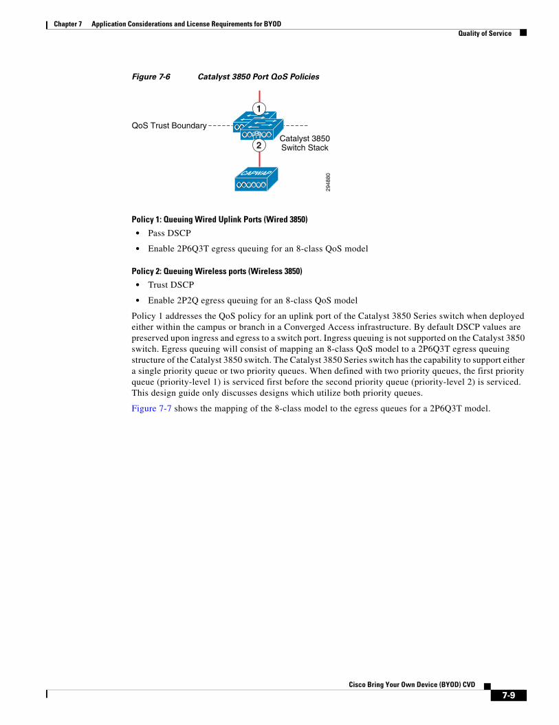
Figure 7-6 shows the Catalyst 3850 port QoS policies.
2948
79
ASA
Converged Access Campus Building Design
Core
RSA
Applications and FileServers
Catalyst 3750Switch Stack
SSIDDownstreamRate Limitingper AP, per
Radio
Data Center
InternetDMVPN
NTP
CT5760WLCs
Services
InternetEdge
WAN
ISE
DNS andDHCP
On-PremMDM
Off-Prem
AD
MDM
Cloud-BasedMDM
CA
CAPWAP Tunnels
Mobility Tunnels(New Mobility Architecture)
CAPWAP CAPWAP
CT5508GuestWLCs
MDM
4
5 5 5
4
36
SGTCapable
GuestSSID
6 MbpsBW, No
Real-TimeTraffic
PersonalDevices
SSIDNo BWLimit,
Real-TimeTraffic
EmployeeSSID
No BWLimit,
Real-TimeTraffic
ProvisioningSSID
No BWLimit, No
Real-TimeTraffic
IT DevicesSSID
No BWLimit, No
Real-TimeTraffic
7-8Cisco Bring Your Own Device (BYOD) CVD
Chapter 7 Application Considerations and License Requirements for BYODQuality of Service
Figure 7-6 Catalyst 3850 Port QoS Policies
Policy 1: Queuing Wired Uplink Ports (Wired 3850)
• Pass DSCP
• Enable 2P6Q3T egress queuing for an 8-class QoS model
Policy 2: Queuing Wireless ports (Wireless 3850)
• Trust DSCP
• Enable 2P2Q egress queuing for an 8-class QoS model
Policy 1 addresses the QoS policy for an uplink port of the Catalyst 3850 Series switch when deployed either within the campus or branch in a Converged Access infrastructure. By default DSCP values are preserved upon ingress and egress to a switch port. Ingress queuing is not supported on the Catalyst 3850 switch. Egress queuing will consist of mapping an 8-class QoS model to a 2P6Q3T egress queuing structure of the Catalyst 3850 switch. The Catalyst 3850 Series switch has the capability to support either a single priority queue or two priority queues. When defined with two priority queues, the first priority queue (priority-level 1) is serviced first before the second priority queue (priority-level 2) is serviced. This design guide only discusses designs which utilize both priority queues.
Figure 7-7 shows the mapping of the 8-class model to the egress queues for a 2P6Q3T model.
2948
80
Catalyst 3850Switch Stack
QoS Trust Boundary
CAPWAP
1
2
7-9Cisco Bring Your Own Device (BYOD) CVD
Chapter 7 Application Considerations and License Requirements for BYODQuality of Service
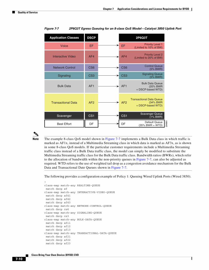
Figure 7-7 2P6Q3T Egress Queuing for an 8-class QoS Model—Catalyst 3850 Uplink Port
Note The example 8-class QoS model shown in Figure 7-7 implements a Bulk Data class in which traffic is marked as AF1x, instead of a Multimedia Streaming class in which data is marked as AF3x, as is shown in some 8-class QoS models. If the particular customer requirements include a Multimedia Streaming traffic class instead of a Bulk Data traffic class, the model can simply be modified to substitute the Multimedia Streaming traffic class for the Bulk Data traffic class. Bandwidth ratios (BWRs), which refer to the allocation of bandwidth within the non-priority queues in Figure 7-7, can also be adjusted as required. WTD refers to the use of weighted tail drop as a congestion avoidance mechanism for the Bulk Data and Transactional Date Queues shown in Figure 7-7.
The following provides a configuration example of Policy 1: Queuing Wired Uplink Ports (Wired 3850).
!class-map match-any REALTIME-QUEUE match dscp efclass-map match-any INTERACTIVE-VIDEO-QUEUE match dscp af41 match dscp af42 match dscp af43class-map match-any NETWORK-CONTROL-QUEUE match dscp cs6class-map match-any SIGNALING-QUEUE match dscp cs3class-map match-any BULK-DATA-QUEUE match dscp af11 match dscp af12 match dscp af13class-map match-any TRANSACTIONAL-DATA-QUEUE match dscp af21 match dscp af22 match dscp af23
Network Control
Signaling
2948
81
Interactive Video
Voice
Application Classes
AF4
EF
DSCP
Scavenger CS1
Best Effort DF
Transactional Data AF2
CS6
CS3
Bulk Data AF1
AF4
EF
2P6Q3T
CS1
DF
AF2
CS6
CS3
AF1
Priority Level 1(Limited to 10% of BW)
Priority Level 2(Limited to 20% of BW)
Control Queue(5% BWR)
Signaling Queue(5% BWR)
Bulk Data Queue(20% BWR
+ DSCP-based WTD)
Transactional Data Queue(34% BWR
+ DSCP-based WTD)
Default Queue(35% BWR + WTD)
Scavenger Queue(1% BWR)
7-10Cisco Bring Your Own Device (BYOD) CVD
Chapter 7 Application Considerations and License Requirements for BYODQuality of Service
class-map match-any SCAVENGER-QUEUE match dscp cs1!policy-map 2P6Q3T class REALTIME-QUEUE priority level 1 police rate percent 10class INTERACTIVE-VIDEO-QUEUE priority level 2 police rate percent 20class NETWORK-CONTROL-QUEUE bandwidth remaining percent 5 queue-buffers ratio 10class SIGNALING-QUEUE bandwidth remaining percent 5 queue-buffers ratio 10class BULK-DATA-QUEUE bandwidth remaining percent 20 queue-buffers ratio 10 queue-limit dscp af13 percent 80 queue-limit dscp af12 percent 90 queue-limit dscp af11 percent 100class TRANSACTIONAL-DATA-QUEUE bandwidth remaining percent 34 queue-buffers ratio 10 queue-limit dscp af23 percent 80 queue-limit dscp af22 percent 90 queue-limit dscp af21 percent 100class SCAVENGER-QUEUE bandwidth remaining percent 1 queue-buffers ratio 10class class-default bandwidth remaining percent 35 queue-buffers ratio 25!interface TenGigabitEthernet 1/1/1 service-policy out 2P6Q3T!
For wired ports, the priority level commands must be defined at the port policy map if the network administrator wishes to place traffic into the priority queues. Policers defined within the wired port policy map constrain the amount of traffic (unicast and/or multicast) through the priority queues.
Figure 7-8 shows an Alternative Policy 1 mapping of the 8-class model to the egress queues for a 2P6Q3T model. This model is discussed here for those customers who desire a port-level QoS policy for the Catalyst 3850 Series switch uplink port, which is consistent with the port-level QoS policy of the CT5760 wireless controller (discussed in Cisco CT5760 Wireless LAN Controller).
7-11Cisco Bring Your Own Device (BYOD) CVD

Chapter 7 Application Considerations and License Requirements for BYODQuality of Service
Figure 7-8 Alternative 2P6Q3T Egress Queuing for an 8-class QoS Model—Catalyst 3850 Uplink
Port
The following provides a configuration example of Alternative Policy 1: Queuing Wired Uplink Ports (Wired 3850).
!class-map match-any RT1 match dscp ef match dscp cs3 match dscp cs6class-map match-any RT2 match dscp af41 match dscp af42 match dscp af43class-map match-any BULK-DATA-QUEUE match dscp af11 match dscp af12 match dscp af13class-map match-any TRANSACTIONAL-DATA-QUEUE match dscp af21 match dscp af22 match dscp af23class-map match-any SCAVENGER-QUEUE match dscp cs1!policy-map 2P6Q3T class RT1 priority level 1 police rate percent 10class RT2 priority level 2 police rate percent 20
Network Control
Signaling
2948
82
Interactive Video
Voice
Application Classes
AF4
EF
DSCP
Scavenger CS1
Best Effort DF
Transactional Data AF2
CS6
CS3
Bulk Data AF1
AF4
EFCS6CS3
2P6Q3T
CS1
DF
AF2
AF1
Priority Level 1(Limited to 10% of BW)
Priority Level 2(Limited to 20% of BW)
Unused Queue*
Unused Queue*
*Note only 6 of the 8 potential queues will be used with an 8-class QoS Model
Bulk Data Queue(25% BWR
+ DSCP-based WTD)
Transactional Data Queue(35% BWR
+ DSCP-based WTD)
Default Queue(35% BWR + WTD)
Scavenger Queue(5% BWR)
7-12Cisco Bring Your Own Device (BYOD) CVD
Chapter 7 Application Considerations and License Requirements for BYODQuality of Service
class BULK-DATA-QUEUE bandwidth remaining percent 25 queue-buffers ratio 10 queue-limit dscp af13 percent 80 queue-limit dscp af12 percent 90 queue-limit dscp af11 percent 100class TRANSACTIONAL-DATA-QUEUE bandwidth remaining percent 35 queue-buffers ratio 10 queue-limit dscp af23 percent 80 queue-limit dscp af22 percent 90 queue-limit dscp af21 percent 100class SCAVENGER-QUEUE bandwidth remaining percent 5 queue-buffers ratio 10class class-default bandwidth remaining percent 35 queue-buffers ratio 25!interface TenGigabitEthernet 1/1/1 service-policy out 2P6Q3T!
Traffic marked EF, CS6, and CS3 is bundled into a new traffic class called RT1 and placed into the priority-level 1 queue. Traffic marked as AF4x is placed into a new traffic class called RT2 (instead of Interactive Video) and placed into the priority-level 2 queue. Hence this model only utilizes six of the possible eight egress queues of the Catalyst 3850 series uplink port.
Note Alternative Policy 1 still supports traffic marked with 8 possible different DSCP markings. Hence it will still be referred to as an 8-class QoS model within this document. However it could also be referred to as a 6-class QoS model, since traffic is aggregated into six traffic classes before being mapped to the queues. This is basically due to the way class maps and policy maps are defined for the Cisco Modular QOS CLI (MQC).
Policy 2 addresses the QoS policy for the wireless port of the Catalyst 3850 switch when deployed either within the campus or branch in a Converged Access infrastructure. By default DSCP values are preserved across the wireless SSID boundary with IOS XE 3.3.0SE software release and higher. Ingress queuing is not supported on Catalyst 3850 switches. Egress queuing will consist of mapping an 8-class QoS model to a 2P2Q egress queuing structure of the Catalyst 3850 switch. Figure 7-9 shows the mapping of the 8-class model to the egress queues.
7-13Cisco Bring Your Own Device (BYOD) CVD

Chapter 7 Application Considerations and License Requirements for BYODQuality of Service
Figure 7-9 2P2Q Egress Queuing for an 8-class QoS Model
The following provides a configuration example of Policy 2: Queuing Wireless Uplink Ports (Wireless 3850).
When the Catalyst 3850 switch detects an AP connected to a port, it automatically creates and attaches a policy-map with a hardcoded name “defportafgn” to the port. This policy map is not user configurable. However this hierarchical policy-map has a child policy-map named “port_child_policy” which can be modified by the user. There can only be one child-level port policy, which is applied to all wireless switch ports in a given Catalyst 3850 Series switch or switch stack. An example of the port_child_policy conforming to the eight class DSCP model placed into four queues (2P2Q) is shown below.
!class-map match-any RT1 match dscp cs6 match dscp cs3 match dscp efclass-map match-any RT2 match dscp af41 match dscp af42 match dscp af43!policy-map port_child_policy class non-client-nrt-class bandwidth remaining ratio 7 class RT1 priority level 1 police rate percent 10 conform-action transmit exceed-action drop class RT2 priority level 2 police rate percent 20 conform-action transmit exceed-action drop class class-default bandwidth remaining ratio 63!
Network Control
Signaling
2948
83
Interactive Video
Voice
Application Classes
AF4
EF
DSCP
Scavenger CS1
Best Effort DF
Transactional Data AF2
CS6
CS3
Bulk Data AF1
AF4
EF
CS6
CS3
2P2Q with AFD
DF
AF2
CS1
AF1
Q0Priority Level 1
(Limited to 10% of BW)
Q1Priority Level 2
(Limited to 20% of BW)
Q2Ucast-NRT
(63% BWR)
Q3Mcast-NRT(7% BWR)
7-14Cisco Bring Your Own Device (BYOD) CVD
Chapter 7 Application Considerations and License Requirements for BYODQuality of Service
Traffic marked EF, CS6, and CS3 is bundled into a traffic class called RT1 and placed into the priority-level 1 queue. Traffic marked as AF4x is placed into a traffic class called RT2 (instead of Interactive Video) and placed into the priority-level 2 queue. Switch ports on the Catalyst 3850 are automatically configured to only support at most four queues when the switch port detects a Cisco Aironet access point directly attached. The assignment of the priority level 1 command to the user-defined RT1 class causes traffic which matches the RT1 class to be placed into the first priority queue. The assignment of the priority level 2 command to the user-defined RT2 class causes traffic which matches the RT2 class to be placed into the second priority queue. The client non-real-time queue (also referred to as the Ucast-NRT or unicast non-real-time queue) is assigned all other client unicast traffic which is not placed into either of the real-time queues. The non-client multicast queue (also referred to as the Mcast-NRT or multicast non-client non-real-time queue) is for all other non-client traffic which is not handled by the other three queues.
Note Policy 2 supports traffic marked with 8 possible different DSCP markings. Hence it is referred to as an 8-class QoS model within this document. However it could also be referred to as a 4-class QoS model, since traffic is aggregated into four traffic classes before being mapped to the queues. This is basically due to the way class maps and policy maps are defined for the Cisco Modular QOS CLI (MQC).
The priority level commands must be defined at the child-level of the port policy map if the network administrator wishes to place traffic into the priority queues. Policers defined within the child-level of the port policy map apply to multicast priority traffic only.
Cisco CT5760 Wireless LAN Controller
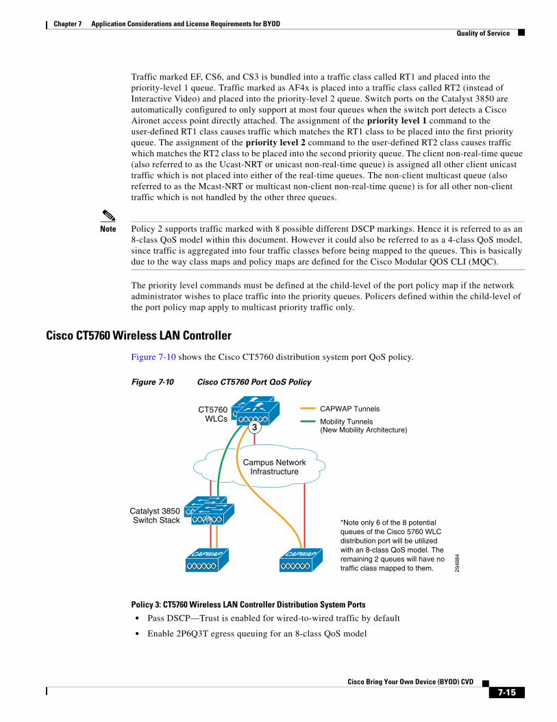
Figure 7-10 shows the Cisco CT5760 distribution system port QoS policy.
Figure 7-10 Cisco CT5760 Port QoS Policy
Policy 3: CT5760 Wireless LAN Controller Distribution System Ports
• Pass DSCP—Trust is enabled for wired-to-wired traffic by default
• Enable 2P6Q3T egress queuing for an 8-class QoS model
Catalyst 3850Switch Stack
CT5760WLCs
2948
84Campus Network
Infrastructure
CAPWAP Tunnels
*Note only 6 of the 8 potential queues of the Cisco 5760 WLC distribution port will be utilized with an 8-class QoS model. The remaining 2 queues will have no traffic class mapped to them.
Mobility Tunnels(New Mobility Architecture)3
CAPWAP CAPWAP
7-15Cisco Bring Your Own Device (BYOD) CVD

Chapter 7 Application Considerations and License Requirements for BYODQuality of Service
Policy 3 addresses the QoS policy for the distribution system port of the Cisco CT5760 wireless controller when deployed either within the campus in a Converged Access infrastructure or as a centralized wireless controller. By default DSCP values are preserved across the wireless SSID boundary with IOS XE 3.3.0SE software release and higher. Ingress queuing is not supported on the Cisco CT5760 wireless controller. Egress queuing will consist of mapping an 8-class QoS model to a 2P6Q3T egress queuing structure of the Cisco CT5760 wireless controller. Figure 7-11 shows the mapping of the 8-class model to the egress queues.
Figure 7-11 2P6Q3T Egress Queuing for an 8-class QoS Model—Cisco CT5760
The following provides a configuration example of Policy 3: Cisco CT5760 Wireless LAN Controller Distribution Ports.
!class-map match-any RT1 match dscp ef match dscp cs3 match dscp cs6class-map match-any RT2 match dscp af41 match dscp af42 match dscp af43class-map match-any BULK-DATA-QUEUE match dscp af11 match dscp af12 match dscp af13class-map match-any TRANSACTIONAL-DATA-QUEUE match dscp af21 match dscp af22 match dscp af23class-map match-any SCAVENGER-QUEUE
Network Control
Signaling
2948
82
Interactive Video
Voice
Application Classes
AF4
EF
DSCP
Scavenger CS1
Best Effort DF
Transactional Data AF2
CS6
CS3
Bulk Data AF1
AF4
EFCS6CS3
2P6Q3T
CS1
DF
AF2
AF1
Priority Level 1(Limited to 10% of BW)
Priority Level 2(Limited to 20% of BW)
Unused Queue*
Unused Queue*
*Note only 6 of the 8 potential queues will be used with an 8-class QoS Model
Bulk Data Queue(25% BWR
+ DSCP-based WTD)
Transactional Data Queue(35% BWR
+ DSCP-based WTD)
Default Queue(35% BWR + WTD)
Scavenger Queue(5% BWR)
7-16Cisco Bring Your Own Device (BYOD) CVD

Chapter 7 Application Considerations and License Requirements for BYODQuality of Service
match dscp cs1!policy-map 2P6Q3T class RT1 priority level 1 police rate percent 10class RT2 priority level 2 police rate percent 20class BULK-DATA-QUEUE bandwidth remaining percent 25 queue-buffers ratio 10 queue-limit dscp af13 percent 80 queue-limit dscp af12 percent 90 queue-limit dscp af11 percent 100class TRANSACTIONAL-DATA-QUEUE bandwidth remaining percent 35 queue-buffers ratio 10 queue-limit dscp af23 percent 80 queue-limit dscp af22 percent 90 queue-limit dscp af21 percent 100class SCAVENGER-QUEUE bandwidth remaining percent 5 queue-buffers ratio 10class class-default bandwidth remaining percent 35 queue-buffers ratio 25!interface TenGigabitEthernet 1/1/1 service-policy out 2P6Q3T!
Traffic marked EF, CS6, and CS3 is bundled into a traffic class called RT1 and placed into the priority-level 1 queue. Traffic marked as AF4x is placed into a traffic class called RT2 (instead of Interactive Video) and placed into the priority-level 2 queue.
Note Policy 3 still supports traffic marked with 8 possible different DSCP markings. Hence it is referred to as an 8-class QoS model within this document. However it could also be referred to as a 6-class QoS model, since traffic is aggregated into six traffic classes before being mapped to the queues. This is basically due to the way class maps and policy maps are defined for the Cisco Modular QOS CLI (MQC).
The assignment of the priority level 1 command to the user-defined RT1 class causes traffic which matches the RT1 class to be placed into the first priority queue. The assignment of the priority level 2 command to the user-defined RT2 class causes traffic which matches the RT2 class to be placed into the second priority queue. The priority level commands must be defined at the child-level of the port policy map if the network administrator wishes to place traffic into the priority queues. Policers defined within the child-level of the port policy map apply to multicast priority traffic only.
Note that with an 8-class QoS model, only six of the eight possible queues on the Cisco CT5760 distribution system port are used. This is slightly different from the Policy 1 design shown for the uplink port of the Catalyst 3850 Series switch since the Catalyst 3850 series switch handles both wired and wireless traffic, while the CT5760 wireless controller handles only wireless traffic. For wireless ports on the Catalyst 3850 series switch and distribution system ports on the CT5760 wireless controller, CS3 and CS6 traffic is mapped to the RT1 queue along with EF traffic in this design. As discussed in SSID-Level QoS Policies, the mapping of CS3 and CS6 traffic to the RT1 queue is also done at the SSID level for the Employee and Personal Devices SSIDs. This is in order to ensure that signaling and network control traffic are not subject to the Approximate Fair Drop (AFD) algorithm within the Unified Access Data Plane (UADP) ASIC. AFD applies to wireless traffic only. Hence for the uplink port of the Catalyst 3850
7-17Cisco Bring Your Own Device (BYOD) CVD
Chapter 7 Application Considerations and License Requirements for BYODQuality of Service
series switch, it is not necessary to place CS3 and CS6 traffic into the priority-level 1 queue. However if a consistent port-level policy map configuration is desired between Catalyst 3850 uplink ports and CT5760 distribution system ports, then Alternative Policy 1 discussed previously can be implemented.
SSID-Level QoS Policies
The SSID-level QoS policies discussed within this section are the same for the Catalyst 3850 Series switches deployed in Converged Access campus designs, Cisco CT5760 wireless LAN controllers deployed in centralized campus designs, and Catalyst 3850 Series switches deployed in Converged Access branch designs. The overall SSID-level policy consists of downstream bandwidth management per SSID, along with the ability to support real-time traffic (voice and/or video) in the downstream direction via the SSID policy map.
The objective of the SSID-level QoS policy in the design presented here is twofold. The first objective is to constrain the downstream bandwidth usage of specific WLANs/SSIDs. In particular this is shown for the Guest WLAN/SSID in order to ensure that the amount of wireless bandwidth consumed by wireless guest traffic does not adversely affect other SSIDs. This assumes that other WLANs/SSIDs have a higher business priority than the Guest WLAN/SSID. However the design can be easily extended to constrain downstream bandwidth usage for multiple WLANs/SSIDs as needed, based on the business requirements of the particular organization.
The second objective is to allow for the support of real-time traffic classes and to constrain the bandwidth usage of those real-time traffic classes on specific WLANs/SSIDs. In particular this is shown for the Employee and Personal Devices WLANs/SSIDs. It is anticipated that these WLANs/SSIDs will support wireless devices which may require real-time applications such as VoIP and video client software. This design assumes that the other WLANs/SSIDs (Guest, Provisioning, and IT Devices) will not have the business requirement for supporting real-time traffic classes. Any real-time traffic on these WLANs/SSIDs is remarked to best effort and treated as non-real-time traffic as it is sent downstream. However, again the design can easily be modified to add or remove the ability to support real-time traffic classes on any WLAN/SSID, as business requirements dictate.
Downstream bandwidth utilization constraints for the five BYOD WLANs/SSIDs are as shown in Figure 7-12.
7-18Cisco Bring Your Own Device (BYOD) CVD

Chapter 7 Application Considerations and License Requirements for BYODQuality of Service
Figure 7-12 Downstream SSID-Level QoS Policies
Policy 4: Downstream SSID Policy
• Pass DSCP—Untrusted command disabled
• Downstream rate limiting of aggregate traffic for Guest SSID
• Priority and policing of real-time traffic for Employee and Personal Devices SSIDs
Campus and Branch Considerations
In the campus it is assumed that the wired infrastructure bandwidth exceeds the wireless bandwidth. Hence the objective is often to simply constrain the downstream bandwidth usage of specific WLANs/SSIDs, such as the Guest SSID, in order to ensure sufficient wireless bandwidth for more business critical WLANs/SSIDs, such as the Employee SSID. In the branch, the wireless bandwidth often exceeds the WAN circuit bandwidth to the branch. Hence the objective of many customers is often to constrain bandwidth usage of specific branch WLANS/SSIDs so that the overall branch WAN bandwidth is not oversubscribed. A common design implemented for branch guest wireless access is to backhaul guest traffic to a dedicated guest wireless LAN controller on a DMZ segment within the campus Internet edge. This is the guest wireless access design discussed within this design guide. Hence the objective of branch deployments is often to constrain the guest wireless access so that it does not utilize all of the branch WAN bandwidth.
2948
85
Catalyst 3850Switch Stack
Converged Access Campus Converged Access BranchCentralized Campus
Catalyst 3850Switch Stack
QoS TrustBoundary
DownstreamSSID
Policies
CAPWAP
4
Cisco CT5780WLCs
CAPWAP
4
Campus NetworkInfrastructure
CAPWAP
4
GuestSSID
6 MbpsBW, No
Real-TimeTraffic
PersonalDevices
SSIDNo BWLimit,
Real-TimeTraffic
EmployeeSSID
No BWLimit,
Real-TimeTraffic
ProvisioningSSID
No BWLimit, No
Real-TimeTraffic
IT DevicesSSID
No BWLimit, No
Real-TimeTraffic
7-19Cisco Bring Your Own Device (BYOD) CVD
Chapter 7 Application Considerations and License Requirements for BYODQuality of Service
The Cisco BYOD solution has two wireless designs for branch locations—a FlexConnect branch design and a Converged Access branch design. In Chapter 21, “BYOD Guest Wireless Access,” the wireless FlexConnect branch design discusses implementing per SSID upstream and downstream rate-limiting. Rate-limiting is actually done on a per-SSID, per-radio, per access point basis. In other words, rate-limiting is actually per BSSID. Hence the chapter includes information abut the following issues:
• The possibility of oversubscribing the desired bandwidth allocation for guest wireless access if multiple access points are deployed within the branch and each access point is allowed a certain amount of bandwidth.
• The possibility of oversubscribing the desired bandwidth allocation if multiple radios (2.4 GHz and 5 GHz) are used per SSID within the branch and each SSID is allowed a certain amount of bandwidth.
• The fact that downstream rate limiting relies on the TCP backoff algorithm in order to throttle traffic by dropping the traffic after it has been sent downstream across the WAN to the branch. Hence the design may not work effectively for UDP traffic flows.
FlexConnect branch designs are often (but not always) implemented for smaller branch designs in which only a handful of access points are deployed at the branch. Hence, although this design is not considered optimal, it may be beneficial to customers with smaller branch deployments.
This section of the design guide focuses only on Converged Access designs. A per-SSID downstream rate-limiting design (similar to the FlexConnect branch design) is shown in the following sections with Converged Access Catalyst 3850 switches at the small branch location. The Guest WLAN/SSID is rate-limited through the use of the shape average command implemented at the parent-level of the downstream SSID policy. However it should be noted that the Converged Access small branch design is targeted for branches with up to 50 access points. Without the ability to constrain bandwidth utilization across the entire SSID (meaning across all access points which implement the SSID within a given branch branch), the per-BSSID design may not provide as much benefit with larger deployments, if the objective is protect the amount of bandwidth utilized across the WAN. Further, backhauling the Guest WLAN/SSID back to a dedicated wireless controller within the campus Internet edge is not a highly scalable model with the Converged Access design. This is due to limitations on the number of mobility tunnels (a total of 71) to controllers within a mobility group. Hence, it is recognized that this design may not necessarily alleviate the issue of WAN bandwidth depletion due to traffic on the Guest WLAN/SSID. Instead the customer may wish to look into deploying a design where guest wireless access is sent directly to the Internet from the branch.
Downstream SSID Policy Configuration Examples
Policy 4 addresses the QoS policy for each of the SSIDs when deployed in any of the following infrastructures:
• Within the campus on a Catalyst 3850 Series switch in a Converged Access design
• Within the campus on a Cisco CT5760 wireless LAN controller in a centralized design
• Within the branch on a Catalyst 3850 Series switch in a Converged Access design
Note that for the CT5760 wireless controller, the SSID policy can differ, depending upon whether a 1P7Q3T or a 2P6Q3T egress port queuing policy has been applied. This is because both real-time queues cannot be utilized at the child-level of the SSID policy map unless both real-time queues are also defined at the child-level of the port policy map. For this design guide, only a 2P6Q3T port egress queuing model is discussed for the CT5760 wireless controller. This is in order to maintain a single downstream SSID policy for each of the WLANs/SSIDs which can be applied for campus Converged Access designs, campus CT5760 centralized wireless controller designs, and branch Converged Access designs.
7-20Cisco Bring Your Own Device (BYOD) CVD
Chapter 7 Application Considerations and License Requirements for BYODQuality of Service
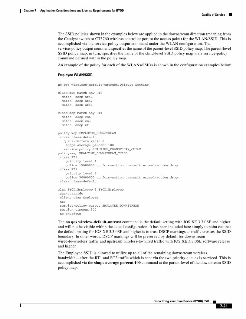
The SSID policies shown in the examples below are applied in the downstream direction (meaning from the Catalyst switch or CT5760 wireless controller port to the access point) for the WLAN/SSID. This is accomplished via the service-policy output command under the WLAN configuration. The service-policy output command specifies the name of the parent-level SSID policy map. The parent-level SSID policy map, in turn, specifies the name of the child-level SSID policy map via a service-policy command defined within the policy map.
An example of the policy for each of the WLANs/SSIDs is shown in the configuration examples below.
Employee WLAN/SSID!no qos wireless-default-untrust/Default Setting!class-map match-any RT2 match dscp af41 match dscp af42 match dscp af43! class-map match-any RT1 match dscp cs6 match dscp cs3 match dscp ef!policy-map EMPLOYEE_DOWNSTREAM class class-default queue-buffers ratio 0 shape average percent 100 service-policy REALTIME_DOWNSTREAM_CHILDpolicy-map REALTIME_DOWNSTREAM_CHILD class RT1 priority level 1 police 15000000 conform-action transmit exceed-action drop class RT2 priority level 2 police 30000000 conform-action transmit exceed-action drop class class-default!wlan BYOD_Employee 1 BYOD_Employee aaa-override client vlan Employee nac service-policy output EMPLOYEE_DOWNSTREAM session-timeout 300 no shutdown!
The no qos wireless-default-untrust command is the default setting with IOS XE 3.3.0SE and higher and will not be visible within the actual configuration. It has been included here simply to point out that the default setting for IOS XE 3.3.0SE and higher is to trust DSCP markings as traffic crosses the SSID boundary. In other words, DSCP markings will be preserved by default for downstream wired-to-wireless traffic and upstream wireless-to-wired traffic with IOS XE 3.3.0SE software release and higher.
The Employee SSID is allowed to utilize up to all of the remaining downstream wireless bandwidth—after the RT1 and RT2 traffic which is sent via the two priority queues is serviced. This is accomplished via the shape average percent 100 command at the parent-level of the downstream SSID policy map.
7-21Cisco Bring Your Own Device (BYOD) CVD

Chapter 7 Application Considerations and License Requirements for BYODQuality of Service
Note The total amount of traffic which can be sent downstream (egress) on the switch port is constrained by a non-configurable internal static shaper for each radio supported by the attached access point. The 5 GHz radio is statically shaped to 400 Mbps, while the 2.4 GHz radio is statically shaped to 200 Mbps.
The reason the shape average percent 100 command is used in the configuration example above is that the parent-level of the downstream SSID policy map must have some constraint defined in order to configure priority queues and policed rates for the RT1 and RT2 traffic defined at the child-level of the SSID policy map.
Within the configuration above, voice (EF), call signaling (CS3), and network control (CS6) traffic are classified into the RT1 traffic class. Video (AF4x) traffic is classified into the RT2 traffic class. The Employee WLAN/SSID is configured to place traffic which matches the RT1 traffic class into the priority-level 1 egress queue and traffic which matches the RT2 traffic class into the priority-level 2 egress queue. In the example configuration, RT1 traffic is policed to 15 Mbps and RT2 traffic is policed to 30 Mbps. Hence the Employee WLAN/SSID is configured to support and rate-limit the amount real-time voice (via the RT1 traffic class) and video (via the RT2 traffic class) traffic sent via the priority queues.
The specific policed rates for RT1 and RT2 traffic will vary per customer, depending upon how much voice and video is required per WLAN/SSID. Choosing the policed rates for RT1 and RT2 traffic may need to take into consideration that the WLAN/SSID policy may apply to both 5 GHz and 2.4 GHz radios, which may have different physical medium rates, if both radios are enabled for a given WLAN/SSID. Obviously one method of resolving this issue would be to enable either the 5 GHz or 2.4 GHz radio for each WLAN/SSID and set the RT1 and RT2 policed rates based on a percentage of the maximum physical medium rate given the radio frequency. An additional factor to consider is type of application. Voice, for example, is well behaved. Hence the policer rate can be calculated based on the maximum number of possible of voice calls. However the actual physical medium rate for a given radio at any given moment depends on many variables, including the number of antennas and spatial streams supported by the mobile device, as well as the signal strength received at the mobile device and access point. Hence the network administrator may need to define policed rates for RT1 and RT2 traffic based on an initial best guess as to the amount of such traffic on the WLAN/SSID, then monitor the policers to determine if drops are occurring and adjust the policed rates up or down accordingly.
The network administrator should note that the definition of the child-level of the downstream WLAN/SSID policy map is only needed when the requirement is to rate-limit (via policers) unicast traffic which matches the RT1 and RT2 (real-time) traffic classes. The definition of the RT1 and RT2 traffic classes at the child-level of the port policy map will already cause traffic which matches these classes to be placed into the priority queues. Rate-limiting of the priority queues puts a limit on the amount of downstream real-time traffic on the WLAN/SSID, so that non-real-time traffic will have some percentage of available bandwidth. The shape average percent command at the parent-level of the downstream SSID policy map refers to the allocation of remaining bandwidth after real-time traffic has been serviced. Hence if real-time traffic is not constrained, it could take up all of the available egress bandwidth of the physical port (up to the non-configurable internal 400 Mbps radio shaped rate for the 5 GHz radio and/or the internal 200 Mbps shaped rate for the 2.4 GHz radio) connecting the Catalyst 3850 switch to the access point.
The shape average command at the parent-level of the downstream SSID policy map is implemented through the Approximate Fair Drop (AFD) algorithm within the Universal Access Data Plane (UADP) ASIC. It is not really a shaper as defined under the Cisco Modular QoS CLI (MQC) syntax. More specifically, the shaper has no buffering capacity and hence no burst (Bc) configuration and no time constant (Tc) associated with the committed information rate (CIR). This is indicated by the queue-buffers ratio 0 command, which must be configured when the shape average command is configured at the parent-level of the downstream SSID policy map.
7-22Cisco Bring Your Own Device (BYOD) CVD
Chapter 7 Application Considerations and License Requirements for BYODQuality of Service
In the example shown above, signaling (CS3) and network control (CS6) traffic are also classified as part of RT1 traffic and placed into the priority-level 1 queue. This is to ensure that signaling and control traffic are not subject to the Approximate Fair Drop (AFD) algorithm within the Unified Access Data Plane (UADP) ASIC. The AFD algorithm is designed to allocate bandwidth fairly between wireless clients on a per access point, per radio, per SSID basis. This provides the benefit that no single wireless client can utilize an excessive amount of downstream wireless bandwidth, degrading the performance for all other wireless clients. AFD accomplishes this by increasing the drop probability for particular wireless client traffic when the amount of downstream traffic destined for that client exceeds an internally calculated “fair-share”. The “fair-share” for a wireless client is dynamically calculated based on the total number of wireless clients per access point, per radio (2.4 GHz or 5 GHz), per SSID, and the amount of congestion occurring at the non-real-time egress queue of the physical port. The amount of congestion occurring is directly related to the aggregate amount of traffic being sent downstream per radio on the SSID. The aggregate effect of AFD operating on all wireless clients per access point, per radio (2.4 GHz or 5 GHz), per SSID is what actually implements the shape average command within the parent-level of the downstream SSID policy map. However traffic placed into the priority-level 1 and priority-level 2 queues are not subject to the AFD algorithm. This is to prevent real-time traffic streams such as voice and video from being unnecessarily degraded by AFD.
The priority-level 1 (RT1) queue has been utilized for signaling (CS3) traffic in the example. Otherwise signaling traffic would be in the class-default traffic class and may have a greater chance of being dropped, affecting voice and video sessions. Traffic in the class-default class includes TCP traffic which is bursty and prone to packet drops. Real-time traffic such as voice and video are UDP based, are well behaved in general, and these classes can more easily be engineered to have no traffic drops. Even though the RT1 and RT2 traffic classes have policers in them, these policing rates can be adjusted so as to ensure no drops. This is the reason the signaling traffic and (CS3) and network control traffic (CS6) are included in RT1 in this design. However if the total amount of voice or video traffic sent downstream on the SSID exceeds the policer defined for the traffic class, then any excess traffic will be dropped. This means that any signaling (CS3) or network control (CS6) traffic included within the traffic class will also be dropped. Voice (EF) traffic is generally more well-known and well behaved and call-admission control (CAC) is more widely deployed for voice calls. Because of this, it is considered less likely that the policer defined for the RT1 traffic class will be exceeded in actual network implementations. Therefore the RT1 traffic class was selected for holding signaling (CS3) and network control (CS6) traffic as well as voice (EF) traffic for the example design.
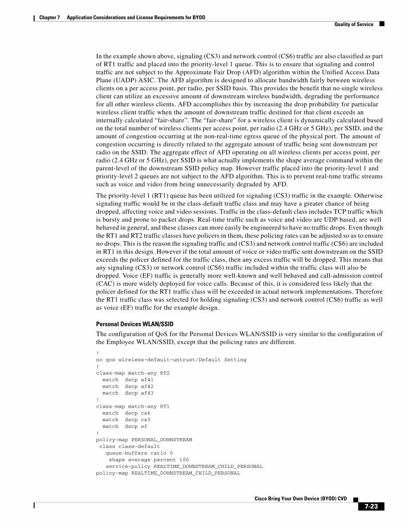
Personal Devices WLAN/SSID
The configuration of QoS for the Personal Devices WLAN/SSID is very similar to the configuration of the Employee WLAN/SSID, except that the policing rates are different.
!no qos wireless-default-untrust/Default Setting!class-map match-any RT2 match dscp af41 match dscp af42 match dscp af43! class-map match-any RT1 match dscp cs6 match dscp cs3 match dscp ef!policy-map PERSONAL_DOWNSTREAM class class-default queue-buffers ratio 0 shape average percent 100 service-policy REALTIME_DOWNSTREAM_CHILD_PERSONALpolicy-map REALTIME_DOWNSTREAM_CHILD_PERSONAL
7-23Cisco Bring Your Own Device (BYOD) CVD
Chapter 7 Application Considerations and License Requirements for BYODQuality of Service
class RT1 priority level 1 police 4500000 conform-action transmit exceed-action drop class RT2 priority level 2 police 9000000 conform-action transmit exceed-action drop class class-default!wlan BYOD_Personal_Device 4 BYOD_Personal_Device client vlan Guest mobility anchor 10.225.50.36 service-policy output PERSONAL_DOWNSTREAM session-timeout 1800 no shutdown!
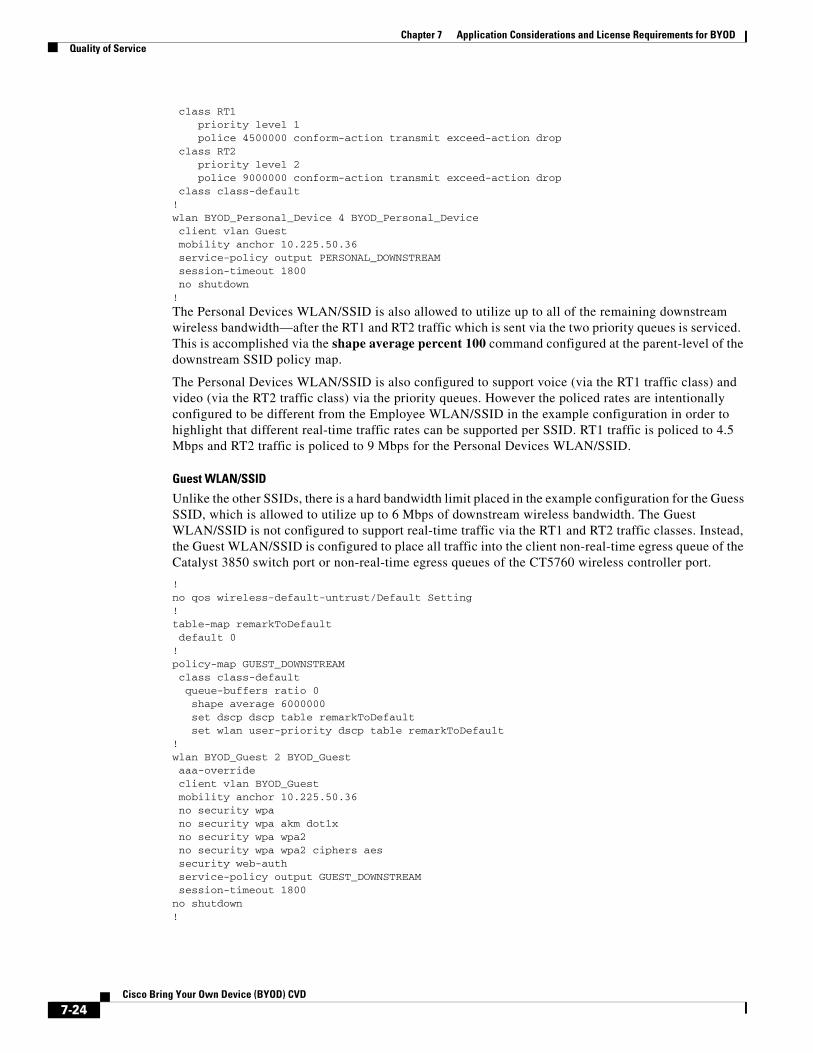
The Personal Devices WLAN/SSID is also allowed to utilize up to all of the remaining downstream wireless bandwidth—after the RT1 and RT2 traffic which is sent via the two priority queues is serviced. This is accomplished via the shape average percent 100 command configured at the parent-level of the downstream SSID policy map.
The Personal Devices WLAN/SSID is also configured to support voice (via the RT1 traffic class) and video (via the RT2 traffic class) via the priority queues. However the policed rates are intentionally configured to be different from the Employee WLAN/SSID in the example configuration in order to highlight that different real-time traffic rates can be supported per SSID. RT1 traffic is policed to 4.5 Mbps and RT2 traffic is policed to 9 Mbps for the Personal Devices WLAN/SSID.
Guest WLAN/SSID
Unlike the other SSIDs, there is a hard bandwidth limit placed in the example configuration for the Guess SSID, which is allowed to utilize up to 6 Mbps of downstream wireless bandwidth. The Guest WLAN/SSID is not configured to support real-time traffic via the RT1 and RT2 traffic classes. Instead, the Guest WLAN/SSID is configured to place all traffic into the client non-real-time egress queue of the Catalyst 3850 switch port or non-real-time egress queues of the CT5760 wireless controller port.
!no qos wireless-default-untrust/Default Setting!table-map remarkToDefault default 0!policy-map GUEST_DOWNSTREAM class class-default queue-buffers ratio 0 shape average 6000000 set dscp dscp table remarkToDefault set wlan user-priority dscp table remarkToDefault!wlan BYOD_Guest 2 BYOD_Guest aaa-override client vlan BYOD_Guest mobility anchor 10.225.50.36 no security wpa no security wpa akm dot1x no security wpa wpa2 no security wpa wpa2 ciphers aes security web-auth service-policy output GUEST_DOWNSTREAM session-timeout 1800no shutdown!
7-24Cisco Bring Your Own Device (BYOD) CVD

Chapter 7 Application Considerations and License Requirements for BYODQuality of Service
Note The examples in this design guide show the same SSID-level policies applied in both campus and branch designs. In actual deployments, the amount of bandwidth configured for the Guest WLAN/SSID at the branch may be lower than that configured for the Guest WLAN/SSID within the campus. This is because the WAN bandwidth connecting the branch to the campus may be the constraining factor for limiting guest wireless bandwidth utilization at the branch.
In the BYOD design within this document, guest traffic is terminated on a DMZ segment within the Internet Edge. This allows only Internet access via the ASA firewall. Hence there should only be traffic with best effort (DSCP 0) markings on the Guest WLAN/SSID. However due to the functioning of QoS at the child-level of the port policy map, if any traffic which matches the RT1 traffic class (EF, CS3, or CS6) is sent downstream, it will be placed into the priority level 1 egress queue at the Catalyst 3850 switch port or CT5760 distribution system port. Likewise if any traffic which matches the RT2 traffic class (AF4x) is sent downstream, it will be placed into the priority level 2 egress queue at the Catalyst 3850 switch port or CT5760 distribution system port. Since there is no child-level of the downstream SSID policy map for the Guest WLAN/SSID, the RT1 and RT2 traffic would also be unconstrained in terms of the amount of bandwidth they could utilize. This presents a potential concern, in that it could result in degradation of actual voice and video calls over other SSIDs. In order to prevent this, a table map which explicitly remarks all traffic back to best effort (DSCP 0) has been included in the downstream SSID policy. This is indicated by the set dscp dscp table remarkToDefault command defined at the parent-level of the downstream SSID policy map. The command applies the table map named remarkToDefault to downstream traffic on the Guest WLAN/SSID. The remarkToDefault table map has a single line which re-marks all traffic to 0 (best effort).
Note also that the 802.11e User Priority (UP) marking of the wireless frame as it is sent over the wireless medium is based upon the DSCP marking of the original IP packet sent downstream. The original Ethernet frame is converted to an 802.11 frame and encapsulated within the CAPWAP header before DSCP and/or UP re-marking occurs. Therefore a second table map which marks the User Priority (UP) of traffic sent over the wireless medium to best effort (UP 0) has also been included in the downstream SSID policy. This is indicated by the set wlan user-priority dscp table remarkToDefault command defined at the parent-level of the downstream SSID policy map.
Provisioning WLAN/SSID!no qos wireless-default-untrust/Default Setting!table-map remarkToDefault default 0!policy-map PROVISIONING_DOWNSTREAM class class-default set dscp dscp table remarkToDefault set wlan user-priority dscp table remarkToDefault!wlan BYOD_Provisioning 3 BYOD_Provisioning aaa-override client vlan Provisioning mac-filtering MAC_ALLOW nac no security wpa no security wpa akm dot1x no security wpa wpa2 no security wpa wpa2 ciphers aes service-policy output PROVISIONING_DOWNSTREAM session-timeout 1800 shutdown!
7-25Cisco Bring Your Own Device (BYOD) CVD
Chapter 7 Application Considerations and License Requirements for BYODQuality of Service
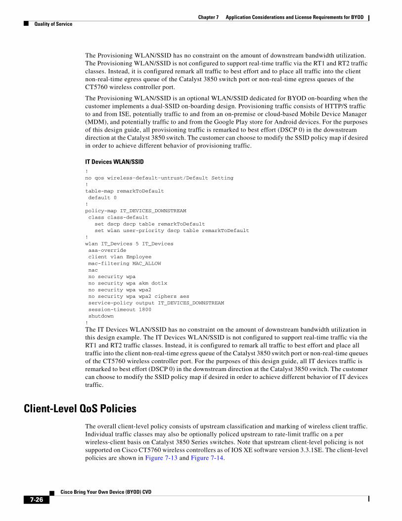
The Provisioning WLAN/SSID has no constraint on the amount of downstream bandwidth utilization. The Provisioning WLAN/SSID is not configured to support real-time traffic via the RT1 and RT2 traffic classes. Instead, it is configured remark all traffic to best effort and to place all traffic into the client non-real-time egress queue of the Catalyst 3850 switch port or non-real-time egress queues of the CT5760 wireless controller port.
The Provisioning WLAN/SSID is an optional WLAN/SSID dedicated for BYOD on-boarding when the customer implements a dual-SSID on-boarding design. Provisioning traffic consists of HTTP/S traffic to and from ISE, potentially traffic to and from an on-premise or cloud-based Mobile Device Manager (MDM), and potentially traffic to and from the Google Play store for Android devices. For the purposes of this design guide, all provisioning traffic is remarked to best effort (DSCP 0) in the downstream direction at the Catalyst 3850 switch. The customer can choose to modify the SSID policy map if desired in order to achieve different behavior of provisioning traffic.
IT Devices WLAN/SSID!no qos wireless-default-untrust/Default Setting!table-map remarkToDefault default 0!policy-map IT_DEVICES_DOWNSTREAM class class-default set dscp dscp table remarkToDefault set wlan user-priority dscp table remarkToDefault!wlan IT_Devices 5 IT_Devices aaa-override client vlan Employee mac-filtering MAC_ALLOW nac no security wpa no security wpa akm dot1x no security wpa wpa2 no security wpa wpa2 ciphers aes service-policy output IT_DEVICES_DOWNSTREAM session-timeout 1800 shutdown!
The IT Devices WLAN/SSID has no constraint on the amount of downstream bandwidth utilization in this design example. The IT Devices WLAN/SSID is not configured to support real-time traffic via the RT1 and RT2 traffic classes. Instead, it is configured to remark all traffic to best effort and place all traffic into the client non-real-time egress queue of the Catalyst 3850 switch port or non-real-time queues of the CT5760 wireless controller port. For the purposes of this design guide, all IT devices traffic is remarked to best effort (DSCP 0) in the downstream direction at the Catalyst 3850 switch. The customer can choose to modify the SSID policy map if desired in order to achieve different behavior of IT devices traffic.
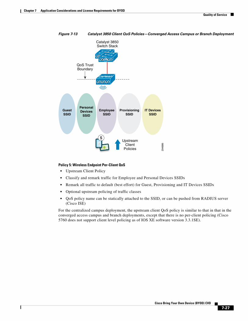
Client-Level QoS PoliciesThe overall client-level policy consists of upstream classification and marking of wireless client traffic. Individual traffic classes may also be optionally policed upstream to rate-limit traffic on a per wireless-client basis on Catalyst 3850 Series switches. Note that upstream client-level policing is not supported on Cisco CT5760 wireless controllers as of IOS XE software version 3.3.1SE. The client-level policies are shown in Figure 7-13 and Figure 7-14.
7-26Cisco Bring Your Own Device (BYOD) CVD
Chapter 7 Application Considerations and License Requirements for BYODQuality of Service
Figure 7-13 Catalyst 3850 Client QoS Policies—Converged Access Campus or Branch Deployment
Policy 5: Wireless Endpoint Per-Client QoS
• Upstream Client Policy
• Classify and remark traffic for Employee and Personal Devices SSIDs
• Remark all traffic to default (best effort) for Guest, Provisioning and IT Devices SSIDs
• Optional upstream policing of traffic classes
• QoS policy name can be statically attached to the SSID, or can be pushed from RADIUS server (Cisco ISE)
For the centralized campus deployment, the upstream client QoS policy is similar to that in that in the converged access campus and branch deployments, except that there is no per-client policing (Cisco 5760 does not support client level policing as of IOS XE software version 3.3.1SE).
2948
86
Catalyst 3850Switch Stack
QoS TrustBoundary
UpstreamClient
Policies
CAPWAP
GuestSSID
PersonalDevices
SSID
EmployeeSSID
ProvisioningSSID
IT DevicesSSID
5
7-27Cisco Bring Your Own Device (BYOD) CVD

Chapter 7 Application Considerations and License Requirements for BYODQuality of Service
Figure 7-14 Cisco 5760 Client QoS Policies—Centralized Campus Deployment
Policy 5: Wireless Endpoint Per-Client QoS
• Upstream Client Policy
• Classify and remark traffic for Employee and Personal Devices SSIDs
• Remark all traffic to default (best effort) for Guest, Provisioning and IT Devices SSIDs
• QoS policy name can be statically attached to the SSID, or can be pushed from RADIUS server (Cisco ISE)
The traffic classes included for specific client level policies will differ based upon the SSID to which the client device is attached. For the Employee and Personal Devices SSIDs, the assumption is that various traffic types will be supported. Other SSIDs treat client traffic as best effort traffic. Table 7-3 shows the application classes and marking for the Employee and Personal Devices SSIDs.
2948
87
QoS TrustBoundary
UpstreamClient
Policies
GuestSSID
PersonalDevices
SSID
EmployeeSSID
ProvisioningSSID
IT DevicesSSID
5
Cisco CT5780WLCs
CAPWAP
Campus NetworkInfrastructure
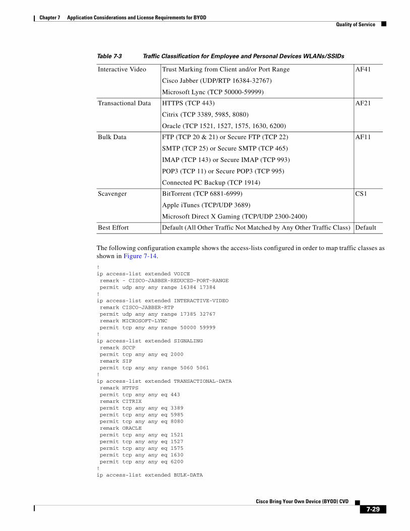
Table 7-3 Traffic Classification for Employee and Personal Devices WLANs/SSIDs
Application Class Classification Criteria Marking
Voice Trust Marking from Client and/or Port Range
Cisco Jabber (UDP/RTP 16384-32767)
EF
Signaling SCCP (TCP 2000) or SIP (TCP 5060-50610 CS3
Network Control Network Control CS6
7-28Cisco Bring Your Own Device (BYOD) CVD
Chapter 7 Application Considerations and License Requirements for BYODQuality of Service
The following configuration example shows the access-lists configured in order to map traffic classes as shown in Figure 7-14.
!ip access-list extended VOICE remark - CISCO-JABBER-REDUCED-PORT-RANGE permit udp any any range 16384 17384!ip access-list extended INTERACTIVE-VIDEO remark CISCO-JABBER-RTP permit udp any any range 17385 32767 remark MICROSOFT-LYNC permit tcp any any range 50000 59999!ip access-list extended SIGNALING remark SCCP permit tcp any any eq 2000 remark SIP permit tcp any any range 5060 5061!ip access-list extended TRANSACTIONAL-DATA remark HTTPS permit tcp any any eq 443 remark CITRIX permit tcp any any eq 3389 permit tcp any any eq 5985 permit tcp any any eq 8080 remark ORACLE permit tcp any any eq 1521 permit tcp any any eq 1527 permit tcp any any eq 1575 permit tcp any any eq 1630 permit tcp any any eq 6200!ip access-list extended BULK-DATA
Interactive Video Trust Marking from Client and/or Port Range
Cisco Jabber (UDP/RTP 16384-32767)
Microsoft Lync (TCP 50000-59999)
AF41
Transactional Data HTTPS (TCP 443)
Citrix (TCP 3389, 5985, 8080)
Oracle (TCP 1521, 1527, 1575, 1630, 6200)
AF21
Bulk Data FTP (TCP 20 & 21) or Secure FTP (TCP 22)
SMTP (TCP 25) or Secure SMTP (TCP 465)
IMAP (TCP 143) or Secure IMAP (TCP 993)
POP3 (TCP 11) or Secure POP3 (TCP 995)
Connected PC Backup (TCP 1914)
AF11
Scavenger BitTorrent (TCP 6881-6999)
Apple iTunes (TCP/UDP 3689)
Microsoft Direct X Gaming (TCP/UDP 2300-2400)
CS1
Best Effort Default (All Other Traffic Not Matched by Any Other Traffic Class) Default
Table 7-3 Traffic Classification for Employee and Personal Devices WLANs/SSIDs
7-29Cisco Bring Your Own Device (BYOD) CVD

Chapter 7 Application Considerations and License Requirements for BYODQuality of Service
remark FTP permit tcp any any eq ftp permit tcp any any eq ftp-data remark SSH/SFTP permit tcp any any eq 22 remark SMTP/SECURE SMTP permit tcp any any eq smtp permit tcp any any eq 465 remark IMAP/SECURE IMAP permit tcp any any eq 143 permit tcp any any eq 993 remark POP3/SECURE POP3 permit tcp any any eq pop3 permit tcp any any eq 995 remark CONNECTED PC BACKUP permit tcp any eq 1914 any!ip access-list extended SCAVENGER remark BITTORRENT permit tcp any any range 6881 6999 remark APPLE ITUNES MUSIC SHARING permit tcp any any eq 3689 permit udp any any eq 3689 remark MICROSOFT DIRECT X GAMING permit tcp any any range 2300 2400 permit udp any any range 2300 2400!
The following configuration example shows the class maps defined for the client-level policies.
!class-map match-any VOICE match dscp ef match access-group VOICE!class-map match-any INTERACTIVE-VIDEO match access-group name INTERACTIVE-VIDEO!class-map match-any SIGNALING match dscp cs3 match access-group name SIGNALING!class-map match-any NETWORK-CONTROL match dscp cs6!class-map match-any TRANSACTIONAL-DATA match access-group name TRANSACTIONAL-DATA!class-map match-any BULK-DATA match access-group name BULK-DATA!class-map match-any SCAVENGER match access-group name SCAVENGER!
Note that the example above intentionally highlights two methods to differentiate voice from video traffic. First, if the wireless client correctly marks voice traffic to EF and video traffic to anything other than EF, then voice traffic can be differentiated simply by its ingress DSCP marking, since typically both voice and video flows utilize the full RTP port range of 16384-32767. However certain applications such as Cisco Unified Communications Manager (CUCM) also give the network administrator the ability to define restricted port ranges for voice and video flows under the control of CUCM. The example above shows Cisco Jabber voice flows being identified by either a DSCP marking of EF or an RTP port range of 16384-17384. Jabber video flows are identified by an RTP port range of 17385-32767. Note that the use of restricted port ranges as a method of differentiating voice from video flows should be used with
7-30Cisco Bring Your Own Device (BYOD) CVD
Chapter 7 Application Considerations and License Requirements for BYODQuality of Service
caution and only when the network administrator has centralized control of the port ranges used by all voice and video streams, as when CUCM is deployed. Otherwise video flows could be misclassified as voice flows and vice-versa.
Note Catalyst 3850 Series switches and CT5760 wireless LAN controllers only support the “match-any” command within class-map definitions. The “match-all” command is not supported as of IOS XE 3.3.1SE.
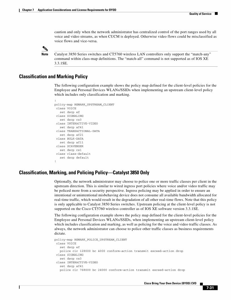
Classification and Marking Policy
The following configuration example shows the policy map defined for the client-level policies for the Employee and Personal Devices WLANs/SSIDs when implementing an upstream client-level policy which includes only classification and marking.
!policy-map REMARK_UPSTREAM_CLIENT class VOICE set dscp ef class SIGNALING set dscp cs3 class INTERACTIVE-VIDEO set dscp af41 class TRANSACTIONAL-DATA set dscp af21 class BULK-DATA set dscp af11 class SCAVENGER set dscp cs1 class class-default set dscp default!
Classification, Marking, and Policing Policy—Catalyst 3850 Only
Optionally, the network administrator may choose to police one or more traffic classes per client in the upstream direction. This is similar to wired ingress port policies where voice and/or video traffic may be policed more from a security perspective. Ingress policing may be applied in order to ensure an intentional or unintentional misbehaving device does not consume all available bandwidth allocated for real-time traffic, which would result in the degradation of all other real-time flows. Note that this policy is only applicable to Catalyst 3850 Series switches. Upstream policing at the client-level policy is not supported on the Cisco CT5760 wireless controller as of IOS XE software version 3.3.1SE.
The following configuration example shows the policy map defined for the client-level policies for the Employee and Personal Devices WLANs/SSIDs, when implementing an upstream client-level policy which includes classification and marking, as well as policing for the voice and video traffic classes. As always, the network administrator can choose to police other traffic classes as business requirements dictate.
policy-map REMARK_POLICE_UPSTREAM_CLIENT class VOICE set dscp ef police cir 128000 bc 4000 conform-action transmit exceed-action drop class SIGNALING set dscp cs3 class INTERACTIVE-VIDEO set dscp af41 police cir 768000 bc 24000 conform-action transmit exceed-action drop
7-31Cisco Bring Your Own Device (BYOD) CVD
Chapter 7 Application Considerations and License Requirements for BYODQuality of Service
class TRANSACTIONAL-DATA set dscp af21 class BULK-DATA set dscp af11 class SCAVENGER set dscp cs1 class class-default set dscp default!
Voice and video traffic flows are typically well-known and configurable in terms of their data rates per client, which lends itself well to implementing ingress policing. In the example client-level policy map above, voice traffic is policed to 128 Kbps and video traffic is policed to 768 Kbps per wireless client, with a time constant (Tc) of 250 milliseconds for each policer. The network administrator will need to take into account the Layer 2 (802.11) and Layer 3 (IP/UDP) protocol overhead when defining the policed rates for voice and video streams. This is not shown, for simplicity, in the example above.
Note The actual traffic rates received by a given client have been observed during validation testing to differ by up to 10-15% from the configured rate. One reason for this may be protocol overhead, since the configured policers and shapers are implemented on the Catalyst 3850 Series switch, and downstream WiFi traffic is encapsulated within both a CAPWAP header as well as a Layer 2 Ethernet header, as it is sent between the Catalyst 3850 Series switch and the Access Point. These headers are stripped off as the 802.11 frame is sent over the WiFi medium and received by the wireless client. Also, the 802.11 WiFi medium itself is inherently contention-based and half-duplex in nature, requiring acknowledgement of each frame, or in some cases groups of frames, received.
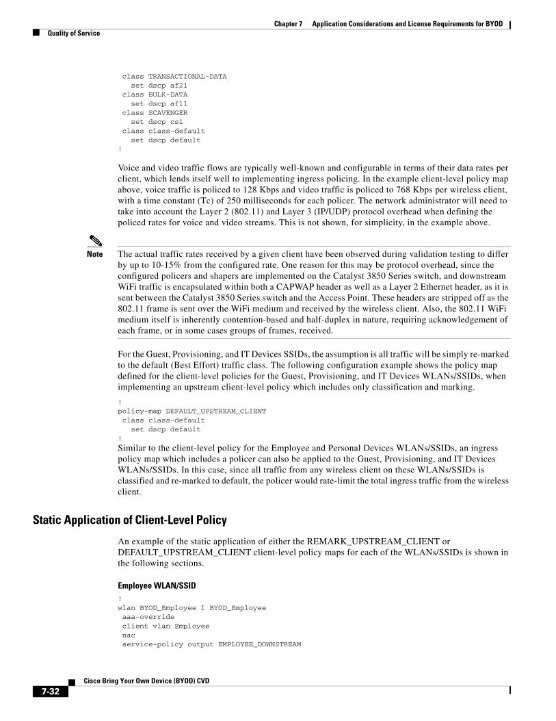
For the Guest, Provisioning, and IT Devices SSIDs, the assumption is all traffic will be simply re-marked to the default (Best Effort) traffic class. The following configuration example shows the policy map defined for the client-level policies for the Guest, Provisioning, and IT Devices WLANs/SSIDs, when implementing an upstream client-level policy which includes only classification and marking.
!policy-map DEFAULT_UPSTREAM_CLIENT class class-default set dscp default!
Similar to the client-level policy for the Employee and Personal Devices WLANs/SSIDs, an ingress policy map which includes a policer can also be applied to the Guest, Provisioning, and IT Devices WLANs/SSIDs. In this case, since all traffic from any wireless client on these WLANs/SSIDs is classified and re-marked to default, the policer would rate-limit the total ingress traffic from the wireless client.
Static Application of Client-Level Policy
An example of the static application of either the REMARK_UPSTREAM_CLIENT or DEFAULT_UPSTREAM_CLIENT client-level policy maps for each of the WLANs/SSIDs is shown in the following sections.
Employee WLAN/SSID!wlan BYOD_Employee 1 BYOD_Employee aaa-override client vlan Employee nac service-policy output EMPLOYEE_DOWNSTREAM
7-32Cisco Bring Your Own Device (BYOD) CVD

Chapter 7 Application Considerations and License Requirements for BYODQuality of Service
service-policy client input REMARK_UPSTREAM_CLIENT session-timeout 300 no shutdown!
For the Employee WLAN/SSID, the REMARK_UPSTREAM_CLIENT policy is applied as an upstream client policy.
Personal Devices WLAN/SSID!wlan BYOD_Personal_Device 4 BYOD_Personal_Device client vlan Guest mobility anchor 10.225.50.36 service-policy output PERSONAL_DOWNSTREAM service-policy client input REMARK_UPSTREAM_CLIENT session-timeout 1800 no shutdown!
For the Personal Devices WLAN/SSID, the REMARK_UPSTREAM_CLIENT policy is also applied as an upstream client policy.
Guest WLAN/SSID!wlan BYOD_Guest 2 BYOD_Guest aaa-override client vlan BYOD_Guest mobility anchor 10.225.50.36 no security wpa no security wpa akm dot1x no security wpa wpa2 no security wpa wpa2 ciphers aes security web-auth service-policy client input DEFAULT_UPSTREAM_CLIENT service-policy output GUEST_DOWNSTREAM session-timeout 1800 no shutdown!
For the Guest WLAN/SSID, the DEFAULT_UPSTREAM_CLIENT policy, which remarks all traffic to Best Effort, is applied as an upstream client policy.
Provisioning WLAN/SSID!wlan BYOD_Provisioning 3 BYOD_Provisioning aaa-override client vlan Provisioning mac-filtering MAC_ALLOW nac no security wpa no security wpa akm dot1x no security wpa wpa2 no security wpa wpa2 ciphers aes service-policy client input DEFAULT_UPSTREAM_CLIENT service-policy output PROVISIONING_DOWNSTREAM session-timeout 1800 no shutdown!
For the Provisioning WLAN/SSID, the DEFAULT_UPSTREAM_CLIENT policy, which remarks all traffic to Best Effort, is also applied as an upstream client policy.
7-33Cisco Bring Your Own Device (BYOD) CVD
Chapter 7 Application Considerations and License Requirements for BYODQuality of Service
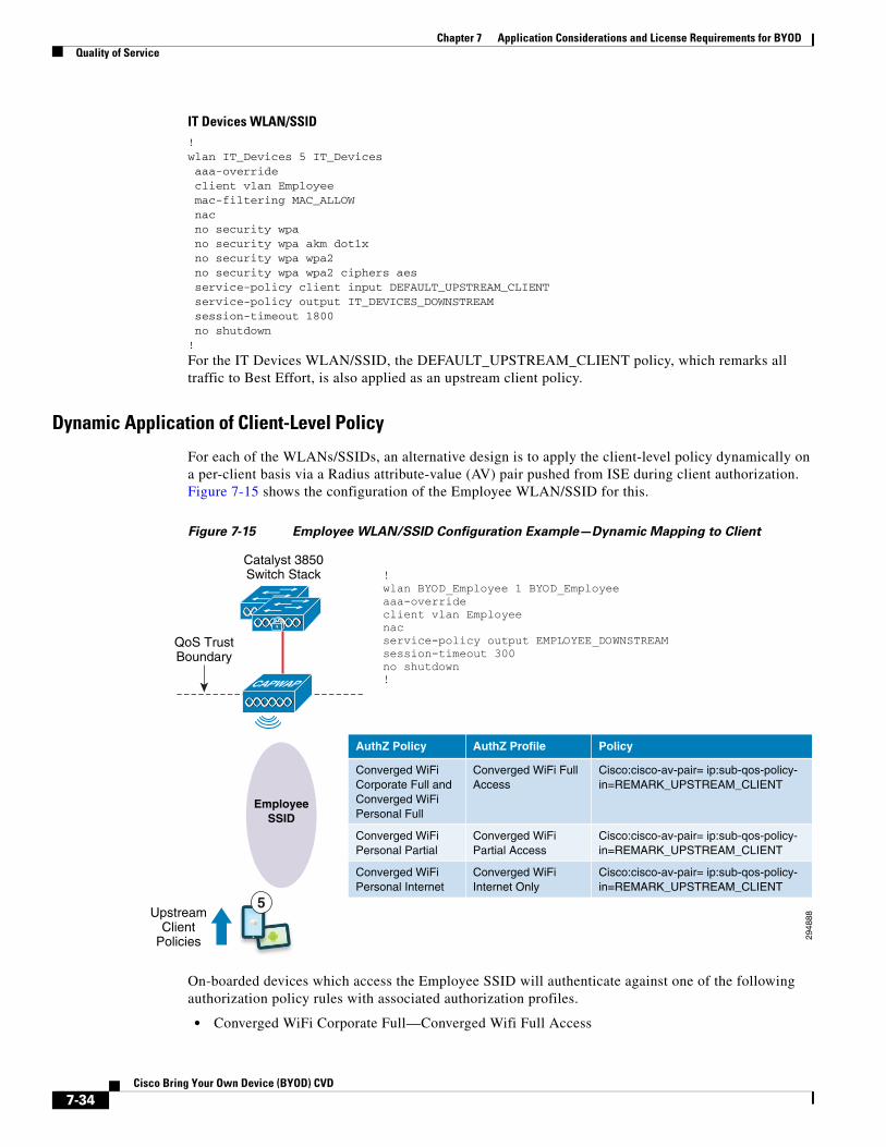
IT Devices WLAN/SSID!wlan IT_Devices 5 IT_Devices aaa-override client vlan Employee mac-filtering MAC_ALLOW nac no security wpa no security wpa akm dot1x no security wpa wpa2 no security wpa wpa2 ciphers aes service-policy client input DEFAULT_UPSTREAM_CLIENT service-policy output IT_DEVICES_DOWNSTREAM session-timeout 1800 no shutdown!
For the IT Devices WLAN/SSID, the DEFAULT_UPSTREAM_CLIENT policy, which remarks all traffic to Best Effort, is also applied as an upstream client policy.
Dynamic Application of Client-Level Policy
For each of the WLANs/SSIDs, an alternative design is to apply the client-level policy dynamically on a per-client basis via a Radius attribute-value (AV) pair pushed from ISE during client authorization. Figure 7-15 shows the configuration of the Employee WLAN/SSID for this.
Figure 7-15 Employee WLAN/SSID Configuration Example—Dynamic Mapping to Client
On-boarded devices which access the Employee SSID will authenticate against one of the following authorization policy rules with associated authorization profiles.
• Converged WiFi Corporate Full—Converged Wifi Full Access
2948
88
Catalyst 3850Switch Stack
QoS TrustBoundary
UpstreamClient
Policies
CAPWAP
EmployeeSSID
5
!wlan BYOD_Employee 1 BYOD_Employeeaaa-overrideclient vlan Employee nacservice-policy output EMPLOYEE_DOWNSTREAMsession-timeout 300no shutdown!
AuthZ Policy AuthZ Profile Policy
Converged WiFi Corporate Full and Converged WiFi Personal Full
Converged WiFi Full Access
Cisco:cisco-av-pair= ip:sub-qos-policy-in=REMARK_UPSTREAM_CLIENT
Converged WiFi Personal Partial
Converged WiFi Partial Access
Cisco:cisco-av-pair= ip:sub-qos-policy-in=REMARK_UPSTREAM_CLIENT
Converged WiFiPersonal Internet
Converged WiFi Internet Only
Cisco:cisco-av-pair= ip:sub-qos-policy-in=REMARK_UPSTREAM_CLIENT
7-34Cisco Bring Your Own Device (BYOD) CVD

Chapter 7 Application Considerations and License Requirements for BYODQuality of Service
• Converged WiFi Personal Full—Converged Wifi Full Access
• Converged WiFi Personal Partial—Converged Wifi Partial Access
• Converged WiFi Personal Internet—Converged Wifi Partial Access
Since these authorization policy rules and associated authorization profiles are unique to Converged Access designs within this design guide, the authorization profiles can be modified to add the following Radius AV pair pushed to the client upon authorization:
cisco:cisco-av-pair=ip:sub-qos-policy-in=REMARK_UPSTREAM_CLIENT
This will dynamically apply the REMARK_UPSTREAM_CLIENT policy to the client upon authorization to the network. This can similarly be done for the other SSIDs so that the upstream client-level policy is dynamically applied for all wireless clients regardless of the WLAN/SSID to which they are connecting.
Note Client-level policies applied dynamically through AAA Radius attribute-value pairs will override any existing client-level policies statically assigned to the WLAN/SSID for the particular client.
Consistent naming of upstream client-level policies is necessary in a Converged Access design. QoS policies are applied at the point-of-attachment (PoA)—meaning the Catalyst 3850 Series switch or CT5760 which controls the access point to which the wireless client is associated. When a wireless client roams between access points controlled by different Catalyst 3850 Series switches (or CT5760 WLCs when implementing a hybrid Converged Access design), the point-of-attachment (PoA) of the wireless client will change. The point-of-attachment (PoA) becomes the current Catalyst 3850 Series switch which controls the access point to which the wireless client is associated, also known as the foreign controller. The point-of-presence (PoP) remains the initial Catalyst 3850 Series switch, also known as the anchor controller. The name of the QoS policy which was pushed down via the Radius AV pair from ISE and dynamically applied to the wireless client when the client authenticated to the network will be sent from the original Catalyst 3850 Series switch (initial PoA) to the current Catalyst 3850 Series switch (current PoA) through the mobility tunnel. This is because the wireless client does not need to re-authenticate when roaming. If the name of the client-level policy map sent through the mobility tunnel does not match any policy maps defined on the new Catalyst 3850 Series switch (the foreign controller), a policy name mismatch occurs, causing the wireless client to be excluded from the foreign controller. Hence roaming will not function properly unless the names of the client-level policies dynamically applied to wireless clients are consistent across Converged Access controllers within the deployment. Note also that when implementing a hybrid Converged Access design, in which CT5760 wireless controllers also directly support access points, policing within the upstream client-level policy is currently not supported. Therefore in order to avoid potential roaming issues, it is not recommended to implement policing in upstream client-level policies which are dynamically applied to wireless clients in a hybrid Converged Access design, even though the Catalyst 3850 Series switches support it.
Mobility Traffic QoS PolicyPolicy 6 in Figure 7-3 through Figure 7-5 indicates the marking of mobility control traffic across the network infrastructure.
With the older non-hierarchical mobility architecture, UDP port 16666 is used to transport unencrypted mobility control packets. UDP port 16667 was used to transport IPsec encrypted mobility control packets, although this protocol is no longer in use as of CUWN 5.x code and higher. Ethernet-over-IP (IP port 97) is used to tunnel the actual mobility data traffic.
7-35Cisco Bring Your Own Device (BYOD) CVD
Chapter 7 Application Considerations and License Requirements for BYODApplication Visibility and Control (AVC)
With the new (hierarchical) mobility architecture, a CAPWAP header (and hence a CAPWAP tunnel) is implemented inside UDP port 16666, which is used to transport mobility control packets. The payload inside the CAPWAP header is also encrypted via DTLS. Hence mobility control packets are encrypted for security. Mobility data traffic is sent via UDP port 16667. The mobility data traffic is also encapsulated within a CAPWAP header (and hence a CAPWAP tunnel) inside UDP port 16667. This replaces the use of Ethernet-over-IP for tunneling mobility data traffic.
Note Converged Access platforms only support the new (hierarchical) mobility architecture.
For this design guide, mobility control traffic between Catalyst 3850 switches and Cisco 5760 wireless controllers is configured to be marked with a DSCP value of 48, corresponding to CS6. The following global configuration command on Catalyst 3860 platforms as well as CT5760 wireless controllers will cause CAPWAP mobility traffic to be marked as CS6:
!wireless mobility dscp 48!
The DSCP marking of wireless mobility data traffic is preserved from the marking the data traffic has as it traverses the CAPWAP tunnel between the access point and the Catalyst 3850 Series switch. Hence the QoS marking of wireless client traffic is preserved during client roaming.
Application Visibility and Control (AVC)Beginning with Cisco Unified Wireless Network (CUWN) software release 7.4, the Application Visibility and Control set of features—already supported on Cisco routing platforms such as ASR 1000s and ISR G2s—became available on WLC platforms, including the Cisco 2500, 5500, 7500, 8500 WLCs, and WiSM2 controllers on Local and FlexConnect Modes (for WLANs configured for central switching only in 7.4 release).
The AVC feature set increases the efficiency, productivity, and manageability of the wireless network. Additionally, the support of AVC embedded within the WLAN infrastructure extends Cisco’s application-based QoS solutions end-to-end.
Business use-cases for AVC policies include:
• Guaranteeing voice quality from wireless applications meets enterprise VoIP requirements.
• Ensuring video applications—both interactive and streaming—are delivered to/from wireless devices with a high Quality of Experience, so that users can communicate and collaborate more efficiently and effectively-regardless of their location or device.
• Provisioning preferred services for business-critical applications running on wireless devices, such as Virtual Desktop applications, sales applications, customer relationship management (CRM) applications, and enterprise resource planning (ERP) applications, etc.
• De-prioritizing “background” application traffic (i.e., applications that send data to/from servers, rather than directly to other users and which do not directly impact user-productivity), such as email, file-transfers, content distribution, backup operations, software updates, etc.
• Identifying and de-prioritizing (or dropping) non-business applications, which can include social networking applications, peer-to-peer file-sharing applications, and type of entertainment and/or gaming applications so that network resources are always available for business-oriented applications.
AVC includes these components:
7-36Cisco Bring Your Own Device (BYOD) CVD
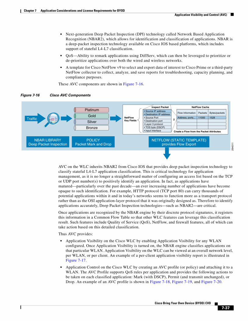
Chapter 7 Application Considerations and License Requirements for BYODApplication Visibility and Control (AVC)
• Next-generation Deep Packet Inspection (DPI) technology called Network Based Application Recognition (NBAR2), which allows for identification and classification of applications. NBAR is a deep-packet inspection technology available on Cisco IOS based platforms, which includes support of stateful L4-L7 classification.
• QoS—Ability to remark applications using DiffServ, which can then be leveraged to prioritize or de-prioritize applications over both the wired and wireless networks.
• A template for Cisco NetFlow v9 to select and export data of interest to Cisco Prime or a third-party NetFlow collector to collect, analyze, and save reports for troubleshooting, capacity planning, and compliance purposes.
These AVC components are shown in Figure 7-16.
Figure 7-16 Cisco AVC Components
AVC on the WLC inherits NBAR2 from Cisco IOS that provides deep packet inspection technology to classify stateful L4-L7 application classification. This is critical technology for application management, as it is no longer a straightforward matter of configuring an access list based on the TCP or UDP port number(s) to positively identify an application. In fact, as applications have matured—particularly over the past decade—an ever increasing number of applications have become opaque to such identification. For example, HTTP protocol (TCP port 80) can carry thousands of potential applications within it and in today’s networks seems to function more as a transport protocol rather than as the OSI application-layer protocol that it was originally designed as. Therefore to identify applications accurately, Deep Packet Inspection technologies—such as NBAR2—are critical.
Once applications are recognized by the NBAR engine by their discrete protocol signatures, it registers this information in a Common Flow Table so that other WLC features can leverage this classification result. Such features include Quality of Service (QoS), NetFlow, and firewall features, all of which can take action based on this detailed classification.
Thus AVC provides:
• Application Visibility on the Cisco WLC by enabling Application Visibility for any WLAN configured. Once Application Visibility is turned on, the NBAR engine classifies applications on that particular WLAN. Application Visibility on the WLC can be viewed at an overall network level, per WLAN, or per client. An example of a per-client application visibility report is illustrated in Figure 7-17.
• Application Control on the Cisco WLC by creating an AVC profile (or policy) and attaching it to a WLAN. The AVC Profile supports QoS rules per application and provides the following actions to be taken on each classified application: Mark (with DSCP), Permit (and transmit unchanged), or Drop. An example of an AVC profile is shown in Figure 7-18, Figure 7-19, and Figure 7-20.
2940
11
Platinum
Gold
Silver
Bronze
• Source IP address• Destination IP address• Source Port• Destination port• Layer 3 protocol• TOS byte (DSCP)• Input Interface
NetFlowKey Fields
NetFlow Cache
Create a Flow from the Packet Attributes
2
Inspect Packet
Traffic
NETFLOW (STATIC TEMPLATE)provides Flow Export
POLICYPacket Mark and Drop
NBAR LIBRARYDeep Packet Inspection
Address, ports......
Flow Information
11000
Packets
1528
Bytes/packets
7-37Cisco Bring Your Own Device (BYOD) CVD
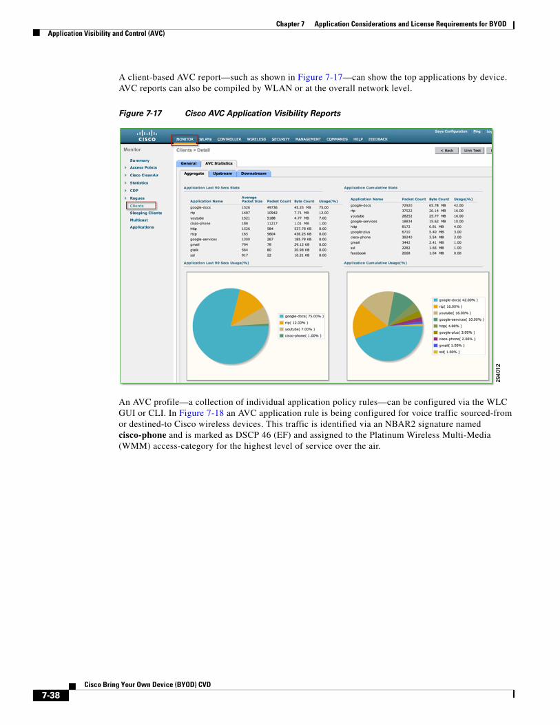
Chapter 7 Application Considerations and License Requirements for BYODApplication Visibility and Control (AVC)
A client-based AVC report—such as shown in Figure 7-17—can show the top applications by device. AVC reports can also be compiled by WLAN or at the overall network level.
Figure 7-17 Cisco AVC Application Visibility Reports
An AVC profile—a collection of individual application policy rules—can be configured via the WLC GUI or CLI. In Figure 7-18 an AVC application rule is being configured for voice traffic sourced-from or destined-to Cisco wireless devices. This traffic is identified via an NBAR2 signature named cisco-phone and is marked as DSCP 46 (EF) and assigned to the Platinum Wireless Multi-Media (WMM) access-category for the highest level of service over the air.
7-38Cisco Bring Your Own Device (BYOD) CVD

Chapter 7 Application Considerations and License Requirements for BYODApplication Visibility and Control (AVC)
Figure 7-18 Cisco AVC Profile Example 1—Creating an AVC Policy Rule
An AVC profile can contain up to 32 individual application rules, as is shown in Figure 7-19, containing recommended policies for the following classes of application traffic (as based on RFC 4594):
• Voice
• Video
• Multimedia Conferencing
• Multimedia Streaming
• Transactional Data
• Bulk Data
• Scavenger applications
7-39Cisco Bring Your Own Device (BYOD) CVD
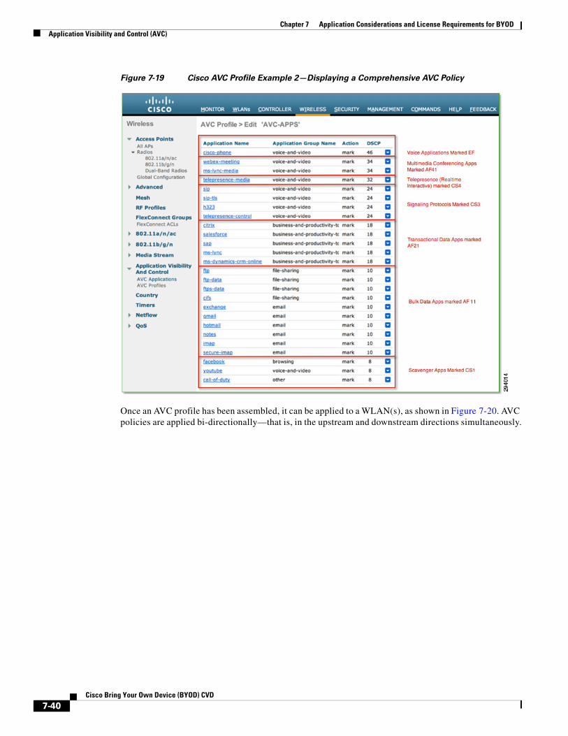
Chapter 7 Application Considerations and License Requirements for BYODApplication Visibility and Control (AVC)
Figure 7-19 Cisco AVC Profile Example 2—Displaying a Comprehensive AVC Policy
Once an AVC profile has been assembled, it can be applied to a WLAN(s), as shown in Figure 7-20. AVC policies are applied bi-directionally—that is, in the upstream and downstream directions simultaneously.
7-40Cisco Bring Your Own Device (BYOD) CVD
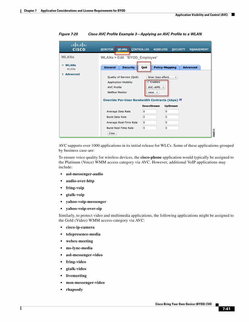
Chapter 7 Application Considerations and License Requirements for BYODApplication Visibility and Control (AVC)
Figure 7-20 Cisco AVC Profile Example 3—Applying an AVC Profile to a WLAN
AVC supports over 1000 applications in its initial release for WLCs. Some of these applications-grouped by business case-are:
To ensure voice quality for wireless devices, the cisco-phone application would typically be assigned to the Platinum (Voice) WMM access category via AVC. However, additional VoIP applications may include:
• aol-messenger-audio
• audio-over-http
• fring-voip
• gtalk-voip
• yahoo-voip-messenger
• yahoo-voip-over-sip
Similarly, to protect video and multimedia applications, the following applications might be assigned to the Gold (Video) WMM access-category via AVC:
• cisco-ip-camera
• telepresence-media
• webex-meeting
• ms-lync-media
• aol-messenger-video
• fring-video
• gtalk-video
• livemeeting
• msn-messenger-video
• rhapsody
7-41Cisco Bring Your Own Device (BYOD) CVD

Chapter 7 Application Considerations and License Requirements for BYODApplication Visibility and Control (AVC)
• skype
• video-over-http
Note It may be that some of these video conferencing applications may be considered non-business in nature (such as Skype and gtalk-video), in which case these may be provisioned into the Bronze (Background) WMM access category.
To deploy AVC policies to protect the signaling protocols relating to these voice and video applications, the following applications might be marked to the Call-Signaling marking of CS3 (DSCP 24) via AVC:
• sip
• sip-tls
• skinny
• telepresence-control
• h323
• rtcp
To deploy policies to protect business-critical applications, the following applications might be marked AF21 (DSCP 18) via AVC:
• citrix
• ms-lync
• ms-dynamics-crm-online
• salesforce
• sap
• oraclenames
• perforce
• phonebook
• semantix
• synergy
On the other hand, some business applications would be best serviced in the background by assigning these to the Bronze (Background) WMM access category via AVC:
• ftp/ftp-data/ftps-data
• cifs
• exchange
• notes
• smtp
• imap/secure imap
• pop3/secure pop3
• gmail
• hotmail
• yahoo-mail
7-42Cisco Bring Your Own Device (BYOD) CVD
Chapter 7 Application Considerations and License Requirements for BYODCisco Jabber
And finally, many non-business applications can be controlled by either being assigned to the Bronze (Background) WMM access category or dropped via AVC policies:
• youtube
• netflix
• bittorrent
• hulu
• itunes
• picasa
• call-of-duty
• doom
• directplay8
Note It is important to note that these are only example applications and do not represent an exhaustive list of applications by class. With over a thousand applications to choose from, these lists are simplified for the sake of brevity and serve only to illustrate AVC policy options and concepts.
For comprehensive design guidance on using the AVC feature for WLCs, see: Chapter 24, “Mobile Traffic Engineering with Application Visibility and Control (AVC).”
Cisco JabberCisco’s Jabber clients are unified communications (UC) applications that are available for Android and Apple mobile devices as well as Microsoft Windows and Apple Mac computers. These client applications provide instant messaging (IM), presence, voice, video, and visual voicemail features. These features require that the employee-owned device is allowed to establish call signaling flows between the device itself and the corporate Cisco Unified Communications Manager (Unified CM) server, typically deployed within the campus data center. Note that the Basic Access use case discussed above terminates employee-owned devices on a DMZ segment off of the Internet Edge firewall. Cisco Jabber requires only Internet access to access WebEx cloud-based services like IM, meetings, and point-to-point voice and video calls. However, to deliver these same services with on-premise corporate assets such as Unified CM and other back-end UC applications, connectivity through the firewall is required for Jabber features to function. In addition to signaling, media flows also need to be allowed between the Jabber client and other IP voice and video endpoints, such as corporate IP phones deployed throughout the corporate network. This requires the network administrator to allow a range of addresses and ports inbound from the DMZ segment through the Internet Edge firewall. Given these connectivity considerations for real time communications and collaboration, the network administrator may instead decide to implement the Enhanced Access use case discussed above. With this BYOD model, the employee-owned devices are on-boarded (registered with the Cisco ISE server and provisioned with digital certificates) and terminated on the inside of the corporate network. This requires no modifications to the Internet Edge firewall, and potentially fewer security concerns.
7-43Cisco Bring Your Own Device (BYOD) CVD
Chapter 7 Application Considerations and License Requirements for BYODCisco Jabber
Cisco Jabber Clients and the Cisco BYOD InfrastructureCisco Jabber, a Cisco mobile client application, provides core Unified Communications and collaboration capabilities, including voice, video, and instant messaging to users of mobile devices such as Android and Apple iOS smartphones and tablets. When a Cisco Jabber client device is attached to the corporate wireless LAN, the client can be deployed within the Cisco Bring Your Own Device (BYOD) infrastructure.
Because Cisco Jabber clients rely on enterprise wireless LAN connectivity or remote secure attachment through VPN, they can be deployed within the Cisco Unified Access network and can utilize the identification, security, and policy features and functions delivered by the BYOD infrastructure.
The Cisco BYOD infrastructure provides a range of access use cases or scenarios to address various device ownership and access requirements. The following high-level access use case models should be considered:
• Enhanced Access—This comprehensive use case provides network access for corporate, personal, and contractor/partner devices. It allows a business to build a policy that enables granular role-based application access and extends the security framework on and off-premises.
• Advanced Access —This use case introduces MDM integration with Enhanced Access.
• Limited Access—Enables access exclusively to corporate issued devices.
• Basic Access—This use case is an extension of traditional wireless guest access. It represents an alternative where the business policy is to not on-board/register employee wireless personal devices, but still provides Internet-only or partial access to the network.
Use Case Impact on JabberThe Enhanced use case allows the simplest path for implementing a Cisco Jabber solution. Cisco Jabber clients, whether running on corporate or personal devices, require access to numerous back-end, on-premise enterprise application components for full functionality. The Enhanced Access use case will allow access from corporate devices with the option of allowing access from personal devices for Jabber back-end applications.
The Limited Access use case will allow Jabber use only from corporate devices.
Basic Access adds a significant layer of complexity for personal devices, requiring them to have access to back-end on-premise Jabber applications from the DMZ. Various signal, control, and media paths must be allowed through the firewall for full functionality.
In the case of cloud-based collaboration services, Cisco mobile clients and devices connect directly to the cloud through the Internet without the need for VPN or full enterprise network attachment. In these scenarios, user and mobile devices can be deployed using the Basic Access model because these use cases require only Internet access.
Other Jabber Design ConsiderationsWhen deploying Cisco Jabber clients within the Cisco BYOD infrastructure, consider the following high-level design and deployment guidelines:
7-44Cisco Bring Your Own Device (BYOD) CVD
Chapter 7 Application Considerations and License Requirements for BYODLicense Requirements for BYOD Solution
• The network administrator should strongly consider allowing voice- and video-capable clients to attach to the enterprise network in the background (after initial provisioning), without user intervention, to ensure maximum use of the enterprises telephony infrastructure. Specifically, use of certificate-based identity and authentication helps facilitate an excellent user experience by minimizing network connection and authentication delay.
• In scenarios where Cisco Jabber clients are able to connect remotely to the enterprise network through a secure VPN:
– The network administrator should weigh the corporate security policy against the need for seamless secure connectivity without user intervention to maximize utilization of the enterprise telephony infrastructure. The use of certificate-based authentication and enforcement of a device PIN lock policy provides seamless attachment without user intervention and functionality similar to two-factor authentication because the end user must possess the device and know the PIN lock to access the network. If two-factor authentication is mandated, then user intervention will be required in order for the device to attach remotely to the enterprise.
– It is important for the infrastructure firewall configuration to allow all required client application network traffic to access the enterprise network. Failure to open access to appropriate ports and protocols at the corporate firewall could result in an inability of Cisco Jabber clients to register to on-premises Cisco call control for voice and video telephony services and/or the loss of other client features such as enterprise directory access or enterprise visual voicemail.
• When enterprise collaboration applications such as Cisco Jabber are installed on employee-owned mobile devices, if the enterprise security policy requires the device to be wiped or reset to factory default settings under certain conditions, device owners should be made aware of the policy and encouraged to backup personal data from their device regularly.
• When deploying Cisco Jabber, it is important for the underlying network infrastructure to support, end-to-end , the necessary QoS classes of service, including priority queuing for voice media and dedicated video and signaling bandwidth, to ensure the quality of client application voice and video calls and appropriate behavior of all features.
For further information regarding Cisco Jabber clients, see the product collateral and documentation at: http://www.cisco.com/go/jabber.
For further information regarding Cisco Mobile Unified Communications, see the Cisco Unified Communications System 9.X SRND at: http://www.cisco.com/en/US/docs/voice_ip_comm/cucm/srnd/9x/mobilapp.html.
License Requirements for BYOD SolutionCisco ISE comes with several license options, such as Evaluation, Base, Advanced, and Wireless. For this design to be implemented, ISE requires the Advanced license option. To obtain more information on licensing, see: http://www.cisco.com/en/US/products/ps11640/tsd_products_support_series_home.html.
7-45Cisco Bring Your Own Device (BYOD) CVD
Chapter 7 Application Considerations and License Requirements for BYODLicense Requirements for BYOD Solution
7-46Cisco Bring Your Own Device (BYOD) CVD