APPENDIX - maui-tomorrow.org
87
APPENDIX ': +LVWRULFDO 6WUXFWXUH $VVHVVPHQW (DVW 0DXL $TXHGXFW 6\VWHP 0DVRQ $UFKLWHFWV ,QF
Transcript of APPENDIX - maui-tomorrow.org

APPENDIX :


Historical Structure Assessment
East Maui Aqueduct System Mason Architects, Inc.
Prepared under contract to WilsonOkamoto
April 2019


HISTORICAL STRUCTURE ASSESSMENT EAST MAUI AQUEDUCT SYSTEM
2
Table of Contents Background and Statement of Objectives............................................................................................... 2
Project Team ....................................................................................................................................................... 3
Methodology ...................................................................................................................................................... 3
Boundary Explanation and Justification..................................................................................................... 4
Setting ................................................................................................................................................................... 4
Historical Overview, East Maui Irrigation..................................................................................................... 7
Irrigation Ditch System Overview ................................................................................................................ 14
Glossary of Other Built Components of the EMI Aqueduct System ................................................. 17
Stream Diversions......................................................................................................................................... 23
Type A Stream Diversion........................................................................................................................... 24
Type A Variation ......................................................................................................................................... 25
Type B Stream Diversion ........................................................................................................................... 26
Type C Stream Diversion .......................................................................................................................... 27
What is a Sluice Gate? .................................................................................................................................. 29
Sluice Gate Types........................................................................................................................................ 26
Ratchet Type ............................................................................................................................................... 27
Geared Type................................................................................................................................................ 28
Board-adjusted Type ................................................................................................................................. 31
Threaded Shaft-Type ................................................................................................................................. 33
Historic Significance and Integrity............................................................................................................ 35
Impact Analysis ................................................................................................................................................ 37
Bibliography ...................................................................................................................................................... 38
Data Sheets/Appendices ............................................................................................................................. 39
Appendix A – Surveyed Resources by Type Appendix B – Photographs of 31 Surveyed Sluice Gates Appendix C – Sketch Plans of 20 EMI Stream Diversions and PhotosAppendix D – Basis for Estimated Construction Dates


HISTORICAL STRUCTURE ASSESSMENT EAST MAUI AQUEDUCT SYSTEM
2
Background and Statement of Objectives In May 2001, Alexander & Baldwin, Inc. (A&B) and its subsidiary, East Maui Irrigation Company,Limited (EMI) (also collectively referred to as A&B), filed an application for the Sale of Lease (WaterLicense) at Public Auction (“Water Lease Application”) with the Board of Land and NaturalResources (BLNR) seeking a long-term (30-year) lease for the “right, privilege, and authority toenter and go upon” the License Area “for the purpose of developing, diverting, transporting, andusing government-owned water” (“Water Lease”).
An Environmental Impact Statement (EIS) is being prepared by Wilson Okamoto Corporation(WOC) in support of the Water Lease Application. At the request of WOC, Mason Architects, Inc.(MAI) has prepared this report to assist the decision-making by assessing the impacts toarchitectural resources if the Water Lease is issued or if other alternative actions are taken.
The Proposed Action constitutes the issuance of a long-term Water Lease for the continued “right,privilege, and authority to enter and go upon” the License Area for the “purpose of developing,diverting, transporting, and using government owned waters” through the existing EMI AqueductSystem to deliver water to the County Of Maui Department of Water Supply (MDWS) for domesticand agricultural water needs in Upcountry Maui, including agricultural users at the Kula AgriculturalPark (KAP), as well as the Nāhiku community. It will also allow for the continued provision of waterto approximately 30,000 acres of agricultural lands (formerly in sugarcane) in Central Maui. TheWater Lease will enable the lessee to continue to go on State-owned lands to maintain and repairexisting access roads and trails used as part of the EMI Aqueduct System.
As an over one hundred-year-old aqueduct system, it is understood that the EMI Aqueduct Systemis a historic resource. The Proposed Action, in itself, does not propose any modifications to the EMIAqueduct System, and, thus will have negligible impact on historic properties. Therefore, andbecause of the expansive size and complexity of the EMI Aqueduct System, this report is less aninventory, and more a reference/typology guide for irrigation systems and their components. Assuch, identification, documentation, and photography of each individual resource is not provided noris there a tally of all historic resources within the License Area, or individual evaluations of eachresource.
Although a decision on the issuance of the Water Lease will not result in any modifications to theEMI Aqueduct System, a recent action taken by the Commission on Water Resource Management(CWRM) that is unrelated to the Water Lease mandates modifications to the EMI Aqueduct System.On June 20, 2018, the CWRM issued a decision and order setting Interim Instream Flow Standards(IIFS) for many of the streams within the License Area. The CWRM decision ordered full streamrestoration for 10 streams and some flow restoration on additional streams. Compliance with theCWRM decision requires modifications to many of the stream diversion works that are part of theEMI Aqueduct System. Diversions requiring partial restoration of stream flow would involveadjustments to sluice gates. Such adjustments are within the normal operation of a diversionstructure, and would have no impact on its historic value. Full stream flow restoration may requireremoval to permanently end the stream diversion function of the sluice gates. Hence, this reportfocuses on those particular components of this extensive aqueduct system. Compliance with theCWRM decision, however, is independent of the Water Lease Application. In other words, themodifications to the stream diversion works needed to comply with the IIFS decision are requiredwhether the Water Lease is issued or not.
Because these modifications are mandated and must be implemented whether or not a WaterLease is issued, the modifications required for implementation of the IIFS are discussed generally

HISTORICAL STRUCTURE ASSESSMENT EAST MAUI AQUEDUCT SYSTEM
resources. This includes reviewing prior reports written on the License Area, including Kalo Kanu OKa Aina, A Cultural Landscape Study of Ke-anae and Wailuanui, Island of Maui (July 1995), as wellas Cultural Surveys Hawai‘i, Inc. Archaeological Literature Review and Field Inspection for theProposed Lease (Water Lease) for the Nāhiku, Ke‘anae, Honomanū, and Huelo License Areas(East Maui Aqueduct System), Multiple Ahupua‘a, Makawao and Hāna District, Maui Island, TMKs:[2] 1-1-001:044, 50, 1-1-002:002, 1-2-004:005, 007 (por.), 2-9-014:001, 005, 011, 012, 017 (2019),other books and newspaper articles. MAI worked closely with EMI Managers Garret Hew and MarkVaught to obtain historical information about the EMI Aqueduct System.
MappingThe locations of the 20 representative stream diversion features are identified on location map(Figure 2).
3
but not analyzed as impacts of the Proposed Action or alternative actions. Under alternativescenarios (No Action Alternative and Reduced Water Lease Alternative), however, additionalmodification to the EMI Aqueduct System would result. This report assesses potential impactsunder those conditions.
Project Team This Historical Structure Assessment was written by MAI under contract to WOC. MAI Research Section Director and architectural historian Polly Tice, and architectural historian Dee Ruzicka, are responsible for its preparation. Dee Ruzicka undertook fieldwork on theEMI Aqueduct System, performed research, and wrote the report. Polly Tice provided projectoversight on scope and content, as well as quality assurance reviews and edits to the writtencontent. Ms. Tice and Mr. Ruzicka both meet and exceed the Secretary of the Interior’s (SOI)Professional Qualification Standards [36 CFR § 61] for Architectural Historian. Trina DeNuccioassisted with graphics preparation, and Leslie Jones assisted with mapping.
Methodology The Proposed Action, in itself, does not propose any modifications to the EMI Aqueduct System,and, thus, will have negligible impact on historic resources. Therefore, and because of theexpansive size and complexity of the EMI Aqueduct System, this report is less an inventory, andmore a reference/typology guide for irrigation systems and their components. As such,identification, documentation, and photography of each individual resource is not provided, nor isthere a tally of all historic resources within the License Area, or individual evaluations of eachresource.
Photographs and FieldworkDigital photographs were taken in the field between May 15 and 18, 2018, of the 20 representativestream diversion features and 31 sluice gate examples. Representative features and exampleswere chosen for this report to illustrate the wide variety of feature types while also being accessiblein the field for photography. For components other than stream diversions and sluice gates thatwere not observed during the fieldwork, photographs in EMI’s files were used in this assessment.All examples of field photos taken by MAI that were used for this report have an orientation /directional notation. MAI worked closely with EMI Managers Garret Hew and Mark Vaught tounderstand how the system works, with the selection of the representative examples of features tobe surveyed for the report, and with coordinating the fieldwork.
Historical ResearchHistorical research was undertaken to assist in developing the context of EMI Aqueduct System’s


HISTORICAL STRUCTURE ASSESSMENT EAST MAUI AQUEDUCT SYSTEM
4
Boundary Explanation and Justification The boundary of the state-owned License Area includes four areas in East Maui, known as the Nāhiku, Ke‘anae, Honomanū, and Huelo License Areas. See Figure 1 map prepared by Wilson Okamoto Corp. for the EIS Preparation Notice. The EMI Aqueduct System operates in a larger Collection Area that includes thousands of acres (privately owned lands in addition to the state- owned lands).
Figure 1: Water lease areas in the EMI system. (Source: Wilson Okamoto Corp.)
Setting The License Area is located completely in East Maui and within the State Land Use Conservation District. The larger Collection Area functions as a watershed to collect rainwater, which is then diverted and transported within the EMI Aqueduct System to the drier, central part of Maui, as well as to the County of Maui Department of Water Supply (MDWS), which in turn services water to Upcountry Maui, including the agricultural users at Kula Agricultural Park (KAP), and the Nāhiku community. As such, the East Maui area is characterized primarily by undeveloped, native forest subject to very high average annual rainfall (approximately 250 inches). Natural features include valleys, streams, waterfalls, and wetland forest. Constructed features include: dams, ditches, flumes, intakes, siphons, sluice gates, stream diversions, tunnels, roads, bridges, walkways, and weirs.
The EMI Aqueduct System includes 24 miles of ditches, 50 miles of tunnels, various flumes, weirs, aqueducts, small dams, and stream diversion intakes. There are 36 streams identified by CWRM within the License Area1. Of these 36 streams, the EMI Aqueduct System has historically diverted water from 34 of these streams.
1 The Draft Environmental Impact Statement identifies 37 streams within the License Area. CWRM did not identify Puakea Stream within the IIFS.

HISTORICAL STRUCTURE ASSESSMENT EAST MAUI AQUEDUCT SYSTEM
5
Table 1 summarizes the 20 stream diversions surveyed for this report in the EMI Aqueduct System, and their locations are shown in Figure 2. The basis for MAI’s estimated year built dates is provided separately, in Appendix D.
Figure 2: Location map of 20 EMI Aqueduct System features surveyed. (Source: MAI)

HISTORICAL STRUCTURE ASSESSMENT EAST MAUI AQUEDUCT SYSTEM
6
Table 1 – 20 EMI Aqueduct System Stream Diversions Surveyed # Feature Name Estimated
year built Ditch Intake
Type Main Sluice Gate Type (in dam)
2nd Sluice Gate Type (intake)
3rd Sluice Gate Type (throw out)
Additional water throw out gate
Notes
001 Makapipi 1904 Koolau A ratchet 002 Hanawi 1904 Koolau A ratchet
003
Ko Piliula West
1914
Koolau
A
geared x2
geared
Ditch water is co-mingled in impounded pool. Stilling wall and sluice gate at intake.
004 Wai o Hue Pre-1960 Koolau B board adj. board adj. 005 Na ili ili Haele 1920s Lowrie A ratchet Stilling wall. 006 Wailua Nui West 1923 Koolau A ratchet Sluice gate in dam is removed. 007 Wailua Nui East 1923-24 Koolau A ratchet Sluice gate in dam is removed.
008
Wailua Iki West
1923-24
Koolau
A
ratchet
board adj.
Stilling wall and sluice gate at intake.
009
Wailua Iki East
1923-24
Koolau
A
ratchet
board adj.
Stilling wall and sluice gate at intake.
010
Hoolawa Haiku
1923
Haiku
A
geared
ratchet
Stilling wall (submerged) and sluice gate at intake.
011
Banana Intake
1924
Spreckles
A
ratchet
Stilling wall and sluice gate at intake.
012
Main Honomanu
1923-24
Spreckles
A
geared
geared
Stilling wall and sluice gate at intake.
013 Kolea Power House Pre-1960 Koolau B board adj. ratchet thread. shaft 014 Kaaiea 1928 Center C ratchet 015 Hoalua 1929 Lowrie B board adj. ratchet
016
Hoolawa Lii Lii
Pre-1960
Lowrie
A
ratchet
Ditch water is co-mingled in impounded pool.
017 Hoolawa Nui Pre-1960 Lowrie C ratchet
018
Pii Naau
Pre-1960
Koolau
D
board adj.
board adj.
Not an intake, a water throw out from ditch
019
Wai Kamoi
Pre-1960
Center
A
ratchet
Ditch water is co-mingled in impounded pool. Stilling wall.
020
Kolea
Pre-1960
Center
A
ratchet
Ditch water is co-mingled in impounded pool. Stilling wall.
Intake Type Descriptions A = Close the sluice gate in the dam for intake B = Open the intake sluice gate for intake C = Throw out gate controls intake, close throw out sluice gate for intake D = a water throw out from ditch

HISTORICAL STRUCTURE ASSESSMENT EAST MAUI AQUEDUCT SYSTEM
7
Historical Overview, East Maui Irrigation The following history is excerpted with permission from Cultural Surveys Hawaii, Inc.’s Archaeological Literature Review and Field Inspection for the Proposed Lease (Water Lease) for the Nāhiku, Ke‘anae, Honomanū, and Huelo License Areas (East Maui Aqueduct System), Multiple Ahupua‘a, Makawao and Hāna District, Maui Island. TMKs: [2] 1-1-001:044, 50, 1-1-002:002, 1-2- 004:005, 007 (por.), 2-9-014:001, 005, 011, 012, 017.2
The Growth of Early Sugar in East Maui
With the decline of the whaling industry in the Pacific in the mid- to late-1800s, the Hawaiian Islands attracted a new generation of managers, professionals, and entrepreneurs who would reshape the landscape for western enterprises and pursuits. Samuel T. Alexander and Henry P. Baldwin were prominent in this movement. Alexander had been sent from his family home at Lahainaluna to study at Oahu College (Punahou School) in Honolulu followed by studies at Williams College in Massachusetts. Alexander returned to Lahainaluna in 1862 as a teacher, and he is credited with using irrigation for improving the town’s sugar cane and banana yields with his students (Dean 1950).Reverend Dwight Baldwin (1798-1886) had arrived in the Hawaiian Islands in 1831 and was stationed at Lahaina between 1835 and 1870. During the early 1850s, Rev. Baldwin had been granted 2,675 acres of land in northwest Maui. This land holding became the basis for enterprises expanding over areas of West Maui undertaken by his son, Henry P. Baldwin, during subsequent decades of the nineteenth century (Dean 1950).
With the ratification of the treaty of reciprocity with the United States in 1876, the future success of sugar in the Hawaiian Islands seemed assured. At that time, several small plantations in the districts east of Wailuku and Kahului and north of Makawao developed new plans to expand the growing of sugar. The Haiku Plantation, managed by Samuel T. Alexander, as well as the Paia Plantation of Henry P. Baldwin, and the Grove Ranch Plantation of T. H. Hobron all suffered from frequent drought. In 1867, Samuel. T. Alexander proposed a massive construction project to bring mountain water from the streams of East Maui west to their plantations along the slopes of Haleakalā (Kuykendall 1967:64).
The stockholders of the Haiku Plantation agreed to back the project. On 30 September 1876, the government of Hawai‘i gave permission to the plantations of Maui to take water from the principal six streams of the region and convey the water by ditch to their fields, for an annual rental of $100. The grant for the water was to last for 20 years, with the stipulation that the ditch construction be completed within the next two years (Kuykendall 1967:64). The system by which mountain water was brought from East Maui to the Haiku Plantation fields in Ha‘ikū and further west onto the isthmus of Maui was the breakthrough that the sugar industry needed to flourish (Wilcox 1996:127).
2 Prepared for: Wilson Okamoto Corporation. Prepared by: Trevor M. Yucha, B.S., Zachariah D. Royalty, B.S., and Hallett H. Hammatt, Ph.D., of Cultural Surveys Hawai‘i, Inc., Wailuku, Hawai‘i. Job Code: MAUI 26. December 2018.

HISTORICAL STRUCTURE ASSESSMENT EAST MAUI AQUEDUCT SYSTEM
8
The “Hamakua Ditch Company” was organized on November 2, 1876, and specifically allotted the shares and costs and the divisions of water to the various plantations, as thus;
The ownership, share of costs and division of water were 9/20ths Haiku Sugar Company, 5/20ths the Alexander and Baldwin Company, 2/20ths James Alexander, and 4/20ths T. H. Hobron. Construction of the Hamakua Ditch, which consisted of a combination of an open ditch, tunnels and iron pipes, was carried on throughout 1876- 1877. Funding for the project was accomplished by the agency of Castle & Cooke. Castle & Cooke agreed to finance the project, with the belief that Samuel T. Alexander and Henry P. Baldwin could bring the ditch project in for between $25,000 to $50,000 (Kuykendall 1967:64).
Thrum (1877:39-42) in Hawaiian Annual and Almanac for 1878, published a description of the project:
The digging of the ditch was a work of no small magnitude. A large gang of men, sometimes numbering two hundred, was employed in the work, and the providing of food, shelter, tools, etc., was equal to the care of a regiment of soldiers on the march. As the grade of the ditch gradually carried the line of work high up into the woods, cart- roads had to be surveyed and cut from the main road to the shifting camps. All the heavy timbers for flumes, etc. were painfully dragged up hill and down, and in and out of deep gulches, severely taxing the energies and strength of man and beast, while the ever-recurring question of a satisfactory food supply created a demand for everything eatable to be obtained from the natives within ten miles, besides large supplies drawn from Honolulu and abroad. (Thrum 1877:39-42)
When construction got under way, Samuel T. Alexander and Henry P. Baldwin began to find out what a monumental job they had tackled. Torrential rains and landslides plagued the project. Workers had to hack their way through jungle and descend sheer cliffs by rope. When the men balked at the final barrier of the sheer drop of over 300 feet at the Māliko Gulch, Henry P. Baldwin, who had lost an arm in a sugar mill accident, shamed them into returning to work by sliding down a rope with his one good arm (Taylor et al. 1976:87).
In July 1877, the first water began flowing through the ditch. It reached the parched Haiku Plantation 24 hours later – barely one day before the deadline set in the royal grant. Approximately 60 million gallons of water a day were soon running through the aqueduct system. The ditch had cost $80,000, which was paid for by Castle & Cooke. At the same time that the success of the Hamakua Ditch became known in the islands, the wealthy refiner of beet sugar in San Francisco, Claus Spreckels, arrived in Honolulu. Seeing the early success of the Alexander and Baldwin partnership, Spreckels moved fast to do business with the sugar growers of Hawai‘i. Within three weeks, he had bought more than half the sugar crop of 1877 and was laying plans to take over the industry as a one-man monopoly (Taylor et al. 1976:87).
Spreckels had watched the Hamakua-Haiku Ditch development on Maui with special interest, hoping it would fail so that he could pick up the pieces. Anticipating the success for the future of sugar at East Maui, Spreckels acquired 8,000 acres of barren

HISTORICAL STRUCTURE ASSESSMENT EAST MAUI AQUEDUCT SYSTEM
9
plain adjacent to Ha‘ikū and the Alexander & Baldwin properties. He then leased 24,000 acres of Crown land in Wailuku through an agreement with a prominent member of the royal family. In 1882, Spreckels was able to obtain title to these lands in fee simple. All he needed was water. Here, Spreckels turned to his friend, Kalakaua; the newly-elected king of the Hawaiian Islands. Kalakaua dismissed his cabinet, whom had previously turned down Spreckels’ application for water from the same general area as Alexander & Baldwin’s Hamakua Ditch. A new cabinet was appointed by the king, who then approved a new right to water for Spreckels. Spreckels went on to build his own ditch and develop his Maui lands into a profitable sugar plantation (Taylor et al. 1976:88-89).
Spreckels was quick to consolidate his gains. His sugar venture on Maui was named “Hawaiian Commercial & Sugar Company,” His expenditures on irrigation and mill machinery were lavish, and his Spreckelsville plantation was nothing short of magnificent. When Claus Spreckels received permission to the use of water found in East Maui, he built his own ditch from Honomanū stream to Maui’s south shore (Wilcox 1996).
The Rise of Commercial Enterprise in Hāna
A 2 February 1897 article in The Hawaiian Star discusses the future of the Hāna region from the perspective of the continued growth of industry and commerce in Hawai‘i at the turn of the century (The Hawaiian Star 1897). Hāna and the undeveloped slopes of East Maui are described as one of the last natural environments remaining in the State in the following excerpts:
“The district of Hana is one of the least known to the general public of any districts on the Islands. Beyond the fact that there are three sugar plantations, viz: Hana, Reciprocity and Kipahulu, the average citizen of Honolulu knows very little about it. It is one of the districts that, like Kona and Puna, will one of these days awake out of sleep.
The prospects of the Hana district are good. The sugar plantations lie on the belt of the undulating land at the extreme east of the Island. To the northwest of Hana Plantation there is an extent of country stretching for twelve or fourteen miles, which, at one time, supported a large population, but which at present time has only a scattered villages here and there.
The energy to develop these lands must come from without, it can never come from within. Again, it is not only energy and capital that are required, but roads. The roads of the portion of the Hana district have hardly been touched since the days of Dr. Judd, who, so far as memory serves, had the present so-called road constructed.” (The Hawaiian Star 1897:4)
The ambition for successful commercial cultivation in East Maui continued to be the focus of all endeavors throughout the mid- and late-1800s. Sugar, coffee, and rubber plantations were started throughout the region with high hopes of success. A 19 December 1898 article in The Hawaiian Star documents a large land sale in Nāhiku and describes the beginning of “the awakening” of the region to foreign industry in the following excerpts:

HISTORICAL STRUCTURE ASSESSMENT EAST MAUI AQUEDUCT SYSTEM
10
“The land sale which took place at Paia on Saturday afternoon, December 17th, was indeed a phenomenal one. There were three lots for sale, and each of them sold for a little over five times the appraised price.
The lands in question are situated in Nahiku among the Palis of East Maui. A couple years ago it would have been hard to give the land away and no one wanted it, unless the chances of permanent government and therefore capital were assured. So the land lay a waste of guava scrub, ferns, ohia, kukui, lauhala and so forth. The thundering waterfalls crashed over the cliffs and the streams roared over their rocky beds to the ocean, with no tribute to the soil in the shape of irrigation. For miles there would be no habitation.
Now all this is being changed. The district, one of the most fertile on the Islands, awakes out of its lethargy. The valleys which have only heard the roar of the cataract and the rush of the stream will wake to the sound of the steam whistle and the ax, and man will enter upon his kingdom. Cultivation and civilization will reign, but the wild beauty of the Koolau district will be gone. Again this is progress under annexation.” (The Hawaiian Star 1898)
East Maui Irrigation Company
The East Maui Irrigation Company (EMI) Aqueduct System was constructed to deliver water from the abundant watersheds of East Maui into coastal and central isthmus plantations to aid in sugar production. The aqueduct system has been in use for over 134 years and continues to collect water today for both private and municipal entities. The EMI Aqueduct System, at the time of this writing, contains 50 miles of tunnels, 24 miles of open ditches, 13 inverted siphons and flumes, and approximately 388 intakes. In addition, the system is served by approximately 62 miles of private roads, and a solar powered radio telemetry system to monitor ditch flow. The catchment begins at roughly 1,300 ft elevation and delivers water to Central Maui at an elevation of 1,150 ft, covering 18 miles from its western to eastern extent.
Built at a time when Hawai‘i was still an independent kingdom, the EMI Aqueduct System was the first of its kind both in the Pacific and on the West Coast of the U.S. It is also the largest privately financed, constructed, and managed irrigation system in the U.S. The initial construction of the first section of the aqueduct system in the 1870s, named Old Hamakua, began the engineering trend of catchment ditches that would later fuel the sugar industry on Kaua‘i, O‘ahu, Hawai‘i, and Maui, making sugar the major economic sector of Hawai‘i for over a century. The aqueduct system itself is composed of a mosaic of multiple smaller ditches, all built at different times by different groups of financiers and engineers (ASCE 2001).
Hawai‘i was moving through many economic and demographic shifts in the late 1800s following the intensification of Western commerce, including the continued drift of rural populations toward town centers, which made water a highly contested and protected resource on islands such as O‘ahu where these demographic trends were most pronounced. This is largely because water had to be diverted from distant watersheds to support growing cities. The legality surrounding watershed catchment was continuously challenged for leaving too-little water for residents where streams were
HISTORICAL STRUCTURE ASSESSMENT EAST MAUI AQUEDUCT SYSTEM
11
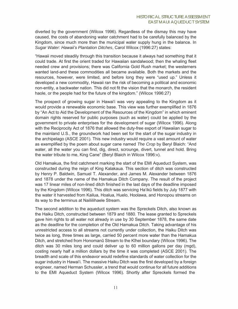
diverted by the government (Wilcox 1996). Regardless of the dismay this may have caused, the costs of abandoning water catchment had to be carefully balanced by the Kingdom, since much more than the municipal water supply hung in the balance. In Sugar Water: Hawaii’s Plantation Ditches, Carol Wilcox (1996:27) states:
“Hawaii moved steadily through this transition because it always had something that it could trade. At first the orient traded for Hawaiian sandalwood; then the whaling fleet needed crew and provisions; there was California Gold Rush market; the westerners wanted land-and these commodities all became available. Both the markets and the resources, however, were limited, and before long they were “used up.” Unless it developed a new commodity, Hawaii ran the risk of becoming a political and economic non-entity, a backwater nation. This did not fit the vision that the monarch, the resident haole, or the people had for the future of the kingdom.” (Wilcox 1996:27)
The prospect of growing sugar in Hawai‘i was very appealing to the Kingdom as it would provide a renewable economic base. This view was further exemplified in 1876 by “An Act to Aid the Development of the Resources of the Kingdom” in which eminent domain rights reserved for public purposes (such as water) could be applied by the government to private enterprises for the development of sugar (Wilcox 1996). Along with the Reciprocity Act of 1876 that allowed the duty-free export of Hawaiian sugar to the mainland U.S., the groundwork had been set for the start of the sugar industry in the archipelago (ASCE 2001). This new industry would require a vast amount of water as exemplified by the poem about sugar cane named The Crop by Beryl Blaich: “And water, all the water you can find, dig, direct, scrounge, divert, tunnel and hold. Bring the water tribute to me, King Cane” (Beryl Blaich in Wilcox 1996:v).
Old Hamakua, the first catchment marking the start of the EMI Aqueduct System, was constructed during the reign of King Kalakaua. This section of ditch was constructed by Henry P. Baldwin, Samuel T. Alexander, and James M. Alexander between 1876 and 1878 under the name of the Hamakua Ditch Company. The result of the project was 17 linear miles of non-lined ditch finished in the last days of the deadline imposed by the Kingdom (Wilcox 1996). This ditch was servicing Ha‘ikū fields by July 1877 with the water it harvested from Kailua, Hoalua, Huelo, Hoolawa, and Honopou streams on its way to the terminus at Nailiilihaele Stream.
The second addition to the aqueduct system was the Spreckels Ditch, also known as the Haiku Ditch, constructed between 1879 and 1880. The lease granted to Spreckels gave him rights to all water not already in use by 30 September 1878, the same date as the deadline for the completion of the Old Hamakua Ditch. Taking advantage of his unrestricted access to all streams not currently under collection, the Haiku Ditch was twice as long, three times as large, carried 50 percent more water than the Hamakua Ditch, and stretched from Honomanū Stream to the Kīhei boundary (Wilcox 1996). The ditch was 30 miles long and could deliver up to 60 million gallons per day (mgd), costing nearly half a million dollars by the time it was completed (ASCE 2001). The breadth and scale of this endeavor would redefine standards of water collection for the sugar industry in Hawai‘i. The massive Haiku Ditch was the first developed by a foreign engineer, named Herman Schussler, a trend that would continue for all future additions to the EMI Aqueduct System (Wilcox 1996). Shortly after Spreckels formed the

HISTORICAL STRUCTURE ASSESSMENT EAST MAUI AQUEDUCT SYSTEM
12
Hawaiian Commercial and Sugar Company (HC&S), construction also began on Center Ditch (1898), Manuel Luis Ditch (1900), and the Lowrie Ditch (1899-1901) by Schussler (ASCE 2001).
In 1898, Spreckels lost controlling interest of HC&S to the agency of Alexander & Baldwin, who took up and completed construction of the Manuel Luis and Lowrie Ditches. Along with the Center Ditch, these two sections completed a lower elevation catchment running through the Hāmākua Loa and Ko‘olau regions. Most notable was the Lowrie Ditch, sometimes called the Lowrie Canal, named after the manager from the HC&S plantation and mills at Spreckelsville, William J. Lowrie. The 22 mile-long Lowrie Ditch could deliver 60 million gallons per day and contained seventy-four tunnels (totaling 20,850 ft, with a single tunnel of 1,955 ft), 19 flumes (totaling 1,965 ft), and 12 siphons carrying water from distant Honomanū Valley to the central isthmus. This ditch was also engineered by a foreign expert, E. L. Van Der Neillen, and constructed by Japanese laborers under the direction of Carl Jensen (Wilcox 1996).
Following the completion of the Manuel Luis/Center/Lowrie Ditch extensions, the next large irrigation project for the Hamakua Ditch Company would be the Koolau Ditch, constructed between 1904 and 1905 by M. M. O’Shaughnessy. This extension of irrigation catchment reached an additional 10 miles toward the Hāna Region and consisted of 7.5 miles of tunnel and 2.5 miles of open ditch and flume. Given the extreme difficulty of working in the narrow and deep gulches of the region it was necessary to build a road alongside the ditch where it passed into tunneled rock, the span of these borings ranged from 300 to 2,710 ft in length (Wilcox 1996). It is this road that was famously travelled by author Jack London in 1905 (The Honolulu Advertiser 1914). This newest ditch section extended out to Makapipi Stream in Nāhiku and cost the Hamakua Ditch Company $511,330 to complete. The Koolau Ditch was constructed concomitantly with the New Hamakua ditch, transferring the Ko‘olau water further west toward Hāmākua Loa, located parallel to the Lowrie ditch but further upslope (Wilcox 1996).
In 1908 the Hamakua Ditch Company was succeeded by their new business entity, EMI. The purpose of this new entity was to develop and administer the surface water collection for all plantation entities under the Alexander & Baldwin umbrella, including the newly acquired Kīhei Plantation. Shortly after this transition, in 1912, EMI added lining to the Koolau Ditch bed and started construction on the Kauhikoa Ditch. The Kauhikoa Ditch collected the water originating in the Koolau/New Hamakua Ditches and carried them further west through Ha‘ikū, Pā‘ia, and further out to Pu‘unene in the central isthmus. This newest extension was completed in 1915 at 29,910 linear ft and carrying 110 million gallons per day. Shortly after starting the Kauhikoa Ditch EMI also started construction of the New Haiku Ditch in 1913. Construction of this lower altitude ditch, running from Halehaku gulch in Peahi to dry North Kīhei, was completed in 1914 with a finished length of 54,044 ft and a daily delivery of 100 mgd. The much longer New Haiku Ditch was completed faster than its Kauhikoa contemporary as the terrain it had to traverse was less severe (Wilcox 1996). Plans for the last major addition to EMI’s catchment system, the Wailoa Ditch, was started in 1918. By the time this ditch was completed in 1923 it was the highest capacity channel in the entire network and had a greater median flow than any natural river in Hawai‘i. The Koolau Ditch was

HISTORICAL STRUCTURE ASSESSMENT EAST MAUI AQUEDUCT SYSTEM
13
connected to the new Wailoa section, being diverted away from the New Hamakua Ditch, and connected to a series of hydro-electric power plants on the north shore of Maui. The Wailoa Ditch consists of 51,256 ft of mostly lined tunnel, and its water capacity ranged from 160 mgd upon completion to a later increased capacity of 195 mgd. This ditch ran parallel to, and above, the earlier New Hamakua and Kauhikoa Ditches (Wilcox 1996).
Upon completion of the major ditch features, EMI commanded the runoff water of a combined 50,000 acres, of which EMI owned 17,000 acres and the State of Hawai‘i owning the balance and directed it toward their 30,000-acre sugar plantation and into Maui Department of Water Supply. Accompanying the water collection infrastructure were 12 siphons, 62 miles of road, 15 miles of telephone line, and numerous small feeders, dams, reservoirs, intakes, pipes, and flumes. The totality of the collection system was managed by four license areas (Huelo, Honomanū, Ke‘anae, and Nāhiku) that dictated the circumstances and conditions under which EMI could collect the runoff from the various Government lands it crossed. The development and improvement of the EMI Aqueduct System over time has cost nearly $5,000,000, compared to its modern assessment of nearly $200,000,000 to create a comparable system.

HISTORICAL STRUCTURE ASSESSMENT EAST MAUI AQUEDUCT SYSTEM
14
Irrigation Ditch System Overview
Figure 3: Typical features found in Hawai‘i’s irrigation ditches (Source: Thematic Context Study: Hawaii’s Irrigation Ditches, Mason Architects, Inc. 2018)

HISTORICAL STRUCTURE ASSESSMENT EAST MAUI AQUEDUCT SYSTEM
15
The EMI Aqueduct System is a network comprised of many different built components, and sluice gates are components of larger, important features. To follow is a general description of a representative Hawaiian sugar cane irrigation system.
A typical Hawaiian irrigation ditch for a sugar plantation originally delivered water across variable terrain, from the source (intake) to the cane fields. Ditch intakes typically consisted of a small dam of lava rock and concrete masonry erected across a stream bed to impound water behind it. As impounded water would rise to a certain level, it would flow into a channel, or intake, behind the dam. This would mark the beginning of that section of ditch. Multiple intakes could be located along the run of a ditch, wherever there was a suitable stream. Generally, the impounding dam was built low across the stream so that a heavy stream flow will wash over it. A light stream flow could be completely occluded by the dam. Occasionally, intake channels were built to accept water from a flowing spring, or from a pumped well.
The layout and design of an irrigation ditch system was planned using a field survey that plotted elevations along the route. The ditch was dug to provide a gradient to keep water flowing, but not so steep as to allow water to build up speed that would result in greater erosion. Generally, the gradient of a ditch was between about 1" to 4" of slope for each 25' of ditch run. Probably the most common treatment of ditch channels that exist today is a relatively thin concrete lining applied to the earth sides and bottom of the ditch. Ditch linings of concrete slabs, masonry of lava rock and concrete mortar, and unlined earth are also found. Sometimes ditches were routed into natural stream beds for a portion of their runs.
Figure 4: Kekaha Ditch, Kaua‘i (possibly above the Mana Plain) ca. 1907. The gate in the photo is the inlet for a siphon. (Source: Private collection of Chris Faye, Kekaha, Kauai)

HISTORICAL STRUCTURE ASSESSMENT EAST MAUI AQUEDUCT SYSTEM
16
In places where ditches were routed across an area with a short and steep drop, concrete raceways were used with deep boxes at their lower ends to collect and still the descending water. Even with a mild gradient, erosion and scour is amplified at turns of the ditch. To minimize this, gentle turns were used where possible and the ditch walls were reinforced at sharper turns, often with lava rock and concrete masonry.
Figure 5: A wooden flume in West Maui. Date unknown. (Source: Wilcox, Sugar Water.)
Whenever possible, ditches were run to follow the contour of the terrain while maintaining their sloping gradient. It was often more expedient to bridge a gulch or canyon rather than weave the ditch completely in and out of gulches. This was accomplished using a flume (Figure 5) for a narrow gulch, and a siphon for a wider gulch or canyon. Although digging a ditch in the open was quicker and cheaper than tunneling, it was likewise often more expedient to go underground and cut a tunnel through ridges rather than follow the contour around them.
Because source water for irrigation ditches was frequently from a stream that flowed most productively during times of heavy rain, when the sugar crop was also getting well-watered, reservoirs were used to store water for times when it was needed most. Sometimes, such as at the Hamakua Coast of the Big Island, ditch water was used primarily for fluming cane to the mills.

HISTORICAL STRUCTURE ASSESSMENT EAST MAUI AQUEDUCT SYSTEM
17
Glossary of Other Built Components of the EMI Aqueduct System Numerous other built components in the EMI Aqueduct System were noted during the selected- sluice gate survey (there are no plans under the current project to modify these features). These are described below.
Bridges Bridges are used along the trail route that provides access to the ditches and their features. Bridges span gulches and streams. They are typically concrete slab construction with either curbs at their edges or solid concrete parapets. Some are inscribed with the year built.
Dams
Figure 6: Bridge at Banana Intake stream diversion carries an access trail over the stream. (Source: MAI, 2018)
Dams are built in the streambed to impound water in order to draw water into ditches. Dams are typically of concrete or masonry (lava rock with concrete mortar) construction. They are typically built with lava cobbles that are laid uncoursed, or are of poured concrete. Some dams are built of faced, uncoursed, irregular lava rock, and some are quarry-faced rectangular blocks laid in courses with concrete mortar. Dams have sluice gates to regulate the amount of water impounded and to allow the stream to flow when no water is needed for the associated intake. Contrast dams with weirs are designed to have water flow over them. Most dams are less than 6' high, however some in larger streambeds can be up to 14' in height.
Figure 7: Dam at Wailuanui West Stream diversion impounds stream water for intake. (Source: MAI, 2018)

HISTORICAL STRUCTURE ASSESSMENT EAST MAUI AQUEDUCT SYSTEM
18
Ditches Ditches carry the collected water along a gently sloping grade across the terrain and deliver it to planted fields. They can be built of varying dimensions, from about 2' wide to over 10' wide and can be unlined or lined with concrete or masonry.
Flumes
Figure 8: Koolau Ditch near Waiohue Stream diversion. View Facing S. (Source: MAI, 2018)
Flumes are used to carry water across a gulch or depressed area of terrain by remaining at ditch gradient. They have the same gentle slope as ditch sections. Historic flumes are typically cast concrete construction with a rectangular cross section and vertical sides that are between 4" and 8" thick. Concrete flumes often have transverse concrete braces across their open tops.
Figure 9: Flume at Koolau Ditch near Waiohue Stream diversion. View Facing N. (Source: MAI, 2018)

HISTORICAL STRUCTURE ASSESSMENT EAST MAUI AQUEDUCT SYSTEM
19
Intakes Intakes are located at stream diversions. They are channels that stream water flows through to be carried from the stream to the ditch. Intakes can have sluice gates at their apertures to control the amount of water taken in, or they can be without a gate. Some intake channels have throw-out sluice gates in their side walls that can be opened to discharge incoming water back out to the stream bed.
Siphons
Figure 10: Intake at Hanawi Stream diversion. View Facing S. (Source: MAI, 2018)
Siphons’ enclosed tubes that carry ditch water across a gulch or depressed area of terrain. Unlike flumes, siphons dip down to follow the depression and then ascend on the opposite side of the gulch. (There are 13 siphons but none were seen during the field work for this report.)
Figure 11: Maliko siphon, unknown date. (Source: EMI archives)

HISTORICAL STRUCTURE ASSESSMENT EAST MAUI AQUEDUCT SYSTEM
20
Stream diversions Stream diversions are features built into a streambed that allow stream water to be taken into a ditch. They generally have a dam or weir to impound a pool of water that is routed into an intake. Stream diversions are masonry or concrete construction, with some metal components such as sluice gates, trash grates, and walkways.
Figure 12: Honomanu Stream diversion. View facing E. (Source: MAI, 2018.)
TunnelsTunnels are built to carry the ditch through the steep terrain of the watershed. Tunnels make up a large portion of the EMI Aqueduct System in East Maui, comprising about two-thirds of the length of the system. Tunnels were dug on a gently sloping grade similar to the standard grade of a ditch.(Most intakes at stream diversions that were visited during field work for this report fed their collected water into a tunneled portion of ditch.)
Figure 13: Tunnel near Kopiliula stream diversion carries water underground at ditch gradient. View facing SE. (Source: MAI, 2018.)

HISTORICAL STRUCTURE ASSESSMENT EAST MAUI AQUEDUCT SYSTEM
21
Walkways Walkways are used to cross gulches above some stream diversions. All of the walkways observed on the field visit for this report are of fairly recent construction of galvanized steel, aluminum, and plastic tread.)
Figure 14: Walkway above Makapipi Stream diversion. View facing S. (Source: MAI, 2018.)
Weirs Weirs are low dams built across a stream to impound water on their upstream side. They are intended to have water flowing over them during times of normal water level and are not high enough to totally obstruct the flow of a stream. Weirs are typically concrete construction or masonry of lava rock and concrete mortar. Some weirs are built with a shallow "v" depression along their top edge to keep the flowing water better channelized in the center of the stream bed.
Figure 15: Wailuanui West Stream diversion. View facing SW. (Source: MAI, 2018.)

HISTORICAL STRUCTURE ASSESSMENT EAST MAUI AQUEDUCT SYSTEM
22

HISTORICAL STRUCTURE ASSESSMENT EAST MAUI AQUEDUCT SYSTEM
23
Stream Diversions Operable sluice gates in stream diversions enable stream water to flow into ditch intakes by opening or closing the gate. Three types of stream diversions were noted during the field work, and are classified in this report by their configuration and whether stream water is taken into the ditch by either closing or opening the sluice gate. Some stream diversions have more than one sluice gate, depending on how they are configured to operate. Nineteen of the twenty features visited during the field work were stream diversions; the one remaining feature is a throw-out sluice gate that discharges water from the ditch itself.

HISTORICAL STRUCTURE ASSESSMENT EAST MAUI AQUEDUCT SYSTEM
24
Type A Stream Diversion Intakes Water by Closing the Sluice Gate
The most common type of stream diversion seen during the field visit (classified as Type A for the purposes of this report), operates using a dam across the stream bed that is equipped with a sluice gate. This type accounts for fourteen of the nineteen stream diversions surveyed. When the sluice gate is closed, water is impounded in a pool above the dam. As the water rises in the pool, it reaches the level of a ditch intake aperture and is able to flow out of the impounded pool, through the aperture, and into the ditch. With the sluice gate in the dam open, stream water flows through the gate and is not impounded sufficiently by the dam to reach the level of the intake. The stream diversions visited used either a ratchet or geared type sluice gate to control the water going through the dam. Some variations to this type of stream diversion were seen, most commonly, the use of a stilling wall in the pool. This wall separates the intake aperture from the rest of the impounded pool.
Figure 16: Type A Stream Diversion Schematic Diagram. (Source: MAI)

HISTORICAL STRUCTURE ASSESSMENT EAST MAUI AQUEDUCT SYSTEM
25
Type A Variation Includes a stilling wall and/or sluice gate at intake
The stilling wall is built to a level slightly below that of the top of the dam. When the dam sluice gate is closed and water backs up in the impounded pool, it flows over the top of the stilling wall and reaches the intake aperture. The stilling wall is designed to reduce the turbulence of the water that reaches the intake aperture from the impounded pool. Some stilling walls are constructed with perforations to allow water flow through them as well as over them. Another variation is a second sluice gate at the intake aperture. This sluice gate would need to be open to allow collected water to flow into the intake.
Figure 17: Type A Stream Diversion Variation Schematic Diagram. (Source: MAI)

HISTORICAL STRUCTURE ASSESSMENT EAST MAUI AQUEDUCT SYSTEM
26
Type B Stream Diversion Intakes Water by Opening the Sluice Gate
This type of stream diversion operates by using a weir across the stream to impound water to a level that reaches the intake aperture. A sluice gate that is installed at the aperture is opened when water is needed in the ditch. When closed, this sluice gate prevents impounded water from entering the intake and the stream water flows over the weir out of the impound and continues down the stream bed. All three of the stream diversions of this type that were observed during the field work use board adjusted sluice gates at the intake apertures and had additional throw-out sluice gates located on the intake channels downstream of the intake apertures, which discharge excess water back into the stream bed when opened.
Figure 18: Type B Stream Diversion Schematic Diagram. (Source: MAI)

HISTORICAL STRUCTURE ASSESSMENT EAST MAUI AQUEDUCT SYSTEM
27
Type C Stream Diversion Intakes Water by Closing a Throw-Out Sluice Gate
This type of stream diversion (used in two of the nineteen diversions surveyed) uses a weir and impounded pool to feed stream water into an intake aperture that is not equipped with a sluice gate. The intake aperture of this type is always open, it has no sluice gate. The amount of water fed into the ditch is controlled by a throw-out sluice gate in the side wall of the intake channel, downstream of the aperture. This throw-out gate, when open, discharges the water flowing into the intake channel back to the stream bed below the weir. When this sluice gate is closed, intake water is not discharged into the stream but continues down the intake channel into the ditch. Both of the diversions of this type observed during field work use a ratchet mechanism on the throw-out sluice gate.
Figure 19: Type C Stream Diversion Schematic Diagram. (Source: MAI)

HISTORICAL STRUCTURE ASSESSMENT EAST MAUI AQUEDUCT SYSTEM
28
Type D Ditch Water Throw-out Uses a Sluice Gate in the Ditch wall to discharge water
One of the features surveyed was not a stream diversion, but a structure designed to stop the flow of water through the ditch. This has two board-adjusted sluice gates; one sluice gate straddles the ditch itself and a second, upstream sluice gate is built into the sidewall of the ditch. The two sluice gates of this structure serve to stop the flow of water through the ditch and to discharge water into a gulch. The wide, board adjusted sluice gate spanning the ditch is closed to block the continued flow of water through the ditch, and impound it above the gate. The second sluice gate, a throw-out gate, is then opened, discharging the impounded water into a gulch. When surveyed there was no water in this ditch, the wide sluice gate straddling the ditch was closed and the throw-out sluice gate in the side of the ditch wall was rendered permanently open by the removal of all boards.
Figure 20: Type D Ditch Water Throw-Out, Schematic Diagram. (Source: MAI)

HISTORICAL STRUCTURE ASSESSMENT EAST MAUI AQUEDUCT SYSTEM
29
What is a Sluice Gate?
Figure 21: Typical sluice gate. Note the vertically sliding panel at the lower end that is operated by the mechanism above. This ratchet-operating gate is located at EMI stream diversion at WailuaIki East, which is ordered to be restored as a “Habitat Stream” by CWRM. (Source: MAI, 2018.)
Figure 22: Typical configuration of sluice gates in a concrete dam. These sluice gates are located at EMI stream diversion at Kopiliula, which is ordered to be restored as a “Habitat Stream by CWRM. View facing N. (Source: MAI, 2018.)
DESCRIPTION A sluice gate is a panel of metal, wood boards, or plastic boards that slides vertically in grooves that are set in the sides of the waterway channel.
FUNCTION Sluice gates control water flow and flow rates. Depending on where they are positioned in a ditch system - and if they are open or closed - they can impound water behind them, allow water to flow into an intake, or throw-out water from a ditch. Sluice gates can either be a component of a larger feature (stream diversion) or a self- contained feature on their own.
Sluice gates can be adjusted by various means, including mechanisms for raising and lowering them. Some of these mechanisms have become inoperable due to lack of use. When necessary, however, they can be serviced to make the adjustments for regulatory compliance.
Figure 23: Typical board adjusted type sluice gate mechanism, shown with the gate closed. This gate is located at EMI stream diversion at Waiohue, which is ordered to be a “Fully Restored” stream by CWRM. View facing SE. (Source: MAI, 2018.)

HISTORICAL STRUCTURE ASSESSMENT EAST MAUI AQUEDUCT SYSTEM
26
Sluice Gate Types Four types of sluice gates were noted during MAI’s field work. Three types use various mechanisms: a ratchet, a gear, or a threaded shaft, to move a solid panel vertically in slots set in the channel. One type is defined by a series of horizontal boards that are slid up and down vertically in slots in the channel. All four of the sluice gate types noted are described and illustrated on the following pages.

HISTORICAL STRUCTURE ASSESSMENT EAST MAUI AQUEDUCT SYSTEM
27
Ratchet Type The ratchet type of mechanism was the most commonly encountered, accounting for sixteen of the thirty-one sluice gates in the twenty stream diversions and other features visited during the field survey. This mechanism operates similarly to a type of automobile jack, using a pawl that engages cross pins that are set in a tall vertical spar fixed to the top of the solid panel. The spar is raised in short increments by a lever that rises the cross pins, allowing the pawl to drop below each pin, arresting any downward movement so the lever can be re-engaged. For lowering the spar, a lever- operated friction brake controls downward movement of the spar when the pawl is released. The ratchet gate mechanisms observed were constructed primarily of painted steel. Some had stainless steel cross pins. Some ratchet mechanisms at the time of the field survey were inoperable due to broken, corroded, or removed parts. Some of these mechanisms have become inoperable due to lack of use. When necessary, however, they can be serviced to make the adjustments to diversions for regulatory compliance. Occasionally, a sluice gate mechanism has been removed by EMI to allow the full flow of stream water to continue past the diversion. This was done to restore full stream flow after the 2016 closing of the HC&S sugar plantation.
Figure 24: This typical ratchet type sluice gate operating mechanism is located at EMI Hoolawaili Stream diversion, on a tributary of Hoolawa, which is ordered to be restored as a “Habitat Stream” by CWRM. View facing SE. (Source: MAI, 2018.)

HISTORICAL STRUCTURE ASSESSMENT EAST MAUI AQUEDUCT SYSTEM
28
Figure 26: This photo illustrates the parts of the sluice gate. Existing modifications to ratchet type sluice gates include the replacement of cross pins (sometimes with stainless steel pins), and placing a locked box over the operating lever area to prevent unauthorized gate adjustments. The integrity of this type of gate can also be affected by the removal of operating parts by EMI to disable the gate, and by corrosion, which can degrade parts and cause them to break or come loose. (Source: MAI, 2018.)
Figure 25: This sluice gate mechanism is a ratchet type. The concrete pedestal and platform it is mounted on is typical of ratchet type gate mechanisms. This ratchet-operating gate is located at EMI stream diversion at Makapipi, which was fully restored in 2008. View facing SE. (Source: MAI, 2018.)

HISTORICAL STRUCTURE ASSESSMENT EAST MAUI AQUEDUCT SYSTEM
29
Geared Type The geared type of mechanism was seen on six of the thirty-one sluice gates in the twenty stream diversions and other features observed. This mechanism operates with a hand cranked pinion gear that raises and lowers a vertically-oriented gear rack affixed to the top of the solid panel of the gate. This mechanism has steel parts, and some examples seen were inoperable due to missing parts that were removed by EMI. Some of these mechanisms have become inoperable due to lack of use. When necessary, however, they can be serviced to make the adjustments to diversion for regulatory compliance.
Figure 27: This typical geared type sluice gate operating mechanism is located at EMI Honomanu Stream diversion, which is ordered to be restored as a “Habitat Stream” by CWRM. View facing SE. (Source: MAI, 2018.)

HISTORICAL STRUCTURE ASSESSMENT EAST MAUI AQUEDUCT SYSTEM
30
Figure 29: View of the same geared mechanism at right.
Figure 28: This sluice gate mechanism is a geared type. It operates by attaching a crank to the shaft of the small pinion gear. Revolving the crank operates the geared mechanism and advances the gear rack, to raise or lower the gates. This geared-operating gate is located at EMI stream diversion at Kopiliula, which is ordered to be restored as a “Habitat Stream” by CWRM. View facing E. (Source: MAI, 2018.)

HISTORICAL STRUCTURE ASSESSMENT EAST MAUI AQUEDUCT SYSTEM
31
Board-adjusted Type This type was found on eight of the thirty-one sluice gates in the twenty stream diversions and other features that were examined. It operates by manually sliding horizontally-oriented boards up and down in the tracks inset in the walls of the channel. Some of these gates were no longer needed and rendered inoperable by removing boards. All of the board adjusted sluice gates seen that were operational were fitted with plastic lumber boards that are held in an open position by stop pins inserted through the gate when it is raised to the desired height.
Figure 30: This typical board adjusted type sluice gate operating mechanism is located at EMI Kolea Power House stream diversion on Kolea, a tributary of Punalau, which is ordered to be restored as a “Habitat Stream” by CWRM. View facing SW. (Source: MAI, 2018.)

HISTORICAL STRUCTURE ASSESSMENT EAST MAUI AQUEDUCT SYSTEM
32
Figure 32: Board adjusted sluice gate with plastic boards installed. Boards are in the closed position, preventing water from passing through the gate. At about 2'-6" wide, this gate is typical width for board adjusted gates seen at EMI during the field survey. This board adjusted gate is located at EMI stream diversion at Waiohue, which is ordered to be a “Fully Restored” stream by CWRM. View facing SE. (Source: MAI, 2018.)
Figure 31: Board adjusted sluice gate with no boards installed. Note that this gate is about 5' wide in total, with three vertical spaces for boards. This board adjusted gate is located at EMI throw-out gate at Piinaau, which is ordered to be a “Fully Restored” stream by CWRM. View facing NE. (Source: MAI, 2018.)

HISTORICAL STRUCTURE ASSESSMENT EAST MAUI AQUEDUCT SYSTEM
33
Threaded Shaft-Type A gate mechanism using a vertical threaded shaft was seen on one of the thirty-one sluice gates. The shaft was fixed to the top of the solid panel gate and was operated by a handwheel that could advance the shaft and gate up or down. The single example of this type of sluice gate seen, was inoperable due to a missing handwheel and severely corroded threaded shaft. Some of these mechanisms have become inoperable due to lack of use. When necessary, however, they can be serviced to make the adjustments to diversions for regulatory compliance.
Figure 33: This threaded shaft type sluice gate operating mechanism is located along an irrigation ditch on the Big Island. It is very similar to the threaded shaft mechanism observed at EMI Kolea Power House stream diversion, on Kolea, a tributary of Punalau, which is ordered to be restored as a “Habitat Stream” by CWRM. The single example surveyed was too damaged to properly illustrate its configuration. (Photo: MAI, 2017.)

HISTORICAL STRUCTURE ASSESSMENT EAST MAUI AQUEDUCT SYSTEM
34
Figure 34: The sluice gate mechanism is a threaded shaft type that is inoperable due to corroded and missing parts. The gate once operated by turning a handwheel that advanced the formerly threaded vertical steel shaft up and down, moving the metal panel. The handwheel is missing and corrosion has destroyed the threads on the steel shaft. Some of these mechanisms have become inoperable due to lack of use. When necessary, however, they can be serviced to make the adjustments. This threaded shaft gate is located at EMI stream diversion at Kolea Power House, on Kolea, a tributary of Punalau, which is ordered to be restored as a “Habitat Stream” by CWRM. View facing S. (Source: MAI, 2018.)
Figure 35: Another view of the threaded shaft gate mechanism at left. This gate is paired with a ratchet type gate. (Source: MAI, 2018.)
HISTORICAL STRUCTURE ASSESSMENT EAST MAUI AQUEDUCT SYSTEM
35
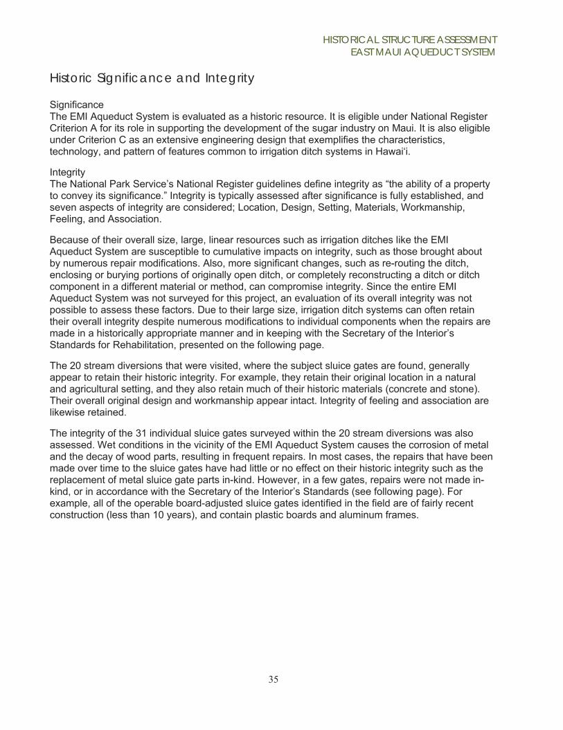
Historic Significance and Integrity Significance The EMI Aqueduct System is evaluated as a historic resource. It is eligible under National Register Criterion A for its role in supporting the development of the sugar industry on Maui. It is also eligible under Criterion C as an extensive engineering design that exemplifies the characteristics, technology, and pattern of features common to irrigation ditch systems in Hawai‘i.
Integrity The National Park Service’s National Register guidelines define integrity as “the ability of a property to convey its significance.” Integrity is typically assessed after significance is fully established, and seven aspects of integrity are considered; Location, Design, Setting, Materials, Workmanship, Feeling, and Association.
Because of their overall size, large, linear resources such as irrigation ditches like the EMI Aqueduct System are susceptible to cumulative impacts on integrity, such as those brought about by numerous repair modifications. Also, more significant changes, such as re-routing the ditch, enclosing or burying portions of originally open ditch, or completely reconstructing a ditch or ditch component in a different material or method, can compromise integrity. Since the entire EMI Aqueduct System was not surveyed for this project, an evaluation of its overall integrity was not possible to assess these factors. Due to their large size, irrigation ditch systems can often retain their overall integrity despite numerous modifications to individual components when the repairs are made in a historically appropriate manner and in keeping with the Secretary of the Interior’s Standards for Rehabilitation, presented on the following page.
The 20 stream diversions that were visited, where the subject sluice gates are found, generally appear to retain their historic integrity. For example, they retain their original location in a natural and agricultural setting, and they also retain much of their historic materials (concrete and stone). Their overall original design and workmanship appear intact. Integrity of feeling and association are likewise retained.
The integrity of the 31 individual sluice gates surveyed within the 20 stream diversions was also assessed. Wet conditions in the vicinity of the EMI Aqueduct System causes the corrosion of metal and the decay of wood parts, resulting in frequent repairs. In most cases, the repairs that have been made over time to the sluice gates have had little or no effect on their historic integrity such as the replacement of metal sluice gate parts in-kind. However, in a few gates, repairs were not made in- kind, or in accordance with the Secretary of the Interior’s Standards (see following page). For example, all of the operable board-adjusted sluice gates identified in the field are of fairly recent construction (less than 10 years), and contain plastic boards and aluminum frames.

HISTORICAL STRUCTURE ASSESSMENT EAST MAUI AQUEDUCT SYSTEM
36
The Secretary of the Interior's Standards for Rehabilitation
The Standards (Department of Interior regulations, 36 CFR 67) pertain to historic buildings of all materials, construction types, sizes, and occupancy and encompass the exterior and the interior, related landscape features and the building's site and environment as well as attached, adjacent, or related new construction. The Standards are to be applied to specific rehabilitation projects in a reasonable manner, taking into consideration economic and technical feasibility.
1. A property shall be used for its historic purpose or be placed in a new use that requires minimal change to the defining characteristics of the building and its site and environment.
2. The historic character of a property shall be retained and preserved. The removal of historic materials or alteration of features and spaces that characterize a property shall be avoided.
3. Each property shall be recognized as a physical record of its time, place, and use. Changes that create a false sense of historical development, such as adding conjectural features or architectural elements from other buildings, shall not be undertaken.
4. Most properties change over time; those changes that have acquired historic significance in their own right shall be retained and preserved.
5. Distinctive features, finishes, and construction techniques or examples of craftsmanship that characterize a property shall be preserved.
6. Deteriorated historic features shall be repaired rather than replaced. Where the severity of deterioration requires replacement of a distinctive feature, the new feature shall match the old in design, color, texture, and other visual qualities and, where possible, materials. Replacement of missing features shall be substantiated by documentary, physical, or pictorial evidence.
7. Chemical or physical treatments, such as sandblasting, that cause damage to historic materials shall not be used. The surface cleaning of structures, if appropriate, shall be undertaken using the gentlest means possible.
8. Significant archeological resources affected by a project shall be protected and preserved. If such resources must be disturbed, mitigation measures shall be undertaken.
9. New additions, exterior alterations, or related new construction shall not destroy historic materials that characterize the property. The new work shall be differentiated from the old and shall be compatible with the massing, size, scale, and architectural features to protect the historic integrity of the property and its environment.
10. New additions and adjacent or related new construction shall be undertaken in such a manner that if removed in the future, the essential form and integrity of the historic property and its environment would be unimpaired.

HISTORICAL STRUCTURE ASSESSMENT EAST MAUI AQUEDUCT SYSTEM
37
Impact Analysis Proposed Action Under the Proposed Action, the State would lease “government-owned water” from the License Area up to the maximum allowable amount under the IIFS.
On June 20th, 2018, CWRM issued a decision and order setting IIFS for many of the streams within the License Area. The CWRM decision ordered full stream restoration for 10 streams and some flow restoration on a number of other streams. Compliance with the CWRM decision requires modifications to many of the stream diversion works that are part of the EMI Aqueduct System. Compliance with the CWRM decision is independent of the Water Lease Application. In other words, the modifications to the stream diversion works needed to comply with the IIFS decision are required whether the Water Lease is issued or not. Because the Proposed Action would authorize the diversion of water up to the maximum allowable amount under the IIFS, there will be no modification to the EMI Aqueduct System, other than those required to comply with the IIFS.
No Action The No Action Alternative would result in no Water Lease being issued by the State.
Under the No Action Alternative, the EMI Aqueduct System could continue to divert non-government-owned water from the Collection Area, i.e. approximately 30 percent of the water available from the Collection Area. To restrict the amount of water diverted to an amount less than allowed under the IIFS means that additional modifications to the EMI Aqueduct System will have to be implemented. Additional modifications, if not undertaken in keeping with the Secretary of the Interior’s Standards, could result in compromised integrity of the aqueduct system’s historic resources.
Should the Water Lease not be awarded, there may be insufficient incentive for EMI to maintain the EMI Aqueduct System, and EMI could abandon the EMI Aqueduct System. Under such a scenario, the aqueduct system’s historic resources may be found at risk for neglect from reduced or lack of maintenance, and/or possible demolition.
Reduced Water Alternative For this alternative, the Water Lease would authorize less water than allowed under the IIFS.
To restrict the amount of water diverted to an amount less than allowed under the IIFS means that additional modifications to the EMI Aqueduct System will have to be implemented. Depending on the amount of water allowed to be collected under this Reduced Water Alternative, there may be insufficient financial incentive for EMI to maintain the EMI Aqueduct System, and EMI could abandon the EMI Aqueduct System.

HISTORICAL STRUCTURE ASSESSMENT EAST MAUI AQUEDUCT SYSTEM
38
Bibliography Dean, Arthur L. Alexander & Baldwin, LTD. and the Predecessor Partnerships. Honolulu: A&B, Ltd).
1950. Dorrance, William H., and Francis S. Morgan. Sugar Islands, The 165-year Story of Sugar in
Hawaii. Honolulu: Mutual Publishing, LLC. 2000. Environment Hawaii, "Complex Legal Issues Surrounding A&B's Taking of East Maui Water."
Website www.environment-hawaii.org. Accessed June 25, 2018.
Group 70 International, Inc., Davianna McGregor, Ph.D. and Cultural Surveys Hawaii, Inc. Kalo Kanu O Ka Aina, A Cultural Landscape Study of Ke’anae and Wailuanui, Island of Maui (July 1995).
Jones, C. Allan, and Robert V. Osgood. From King Cane to the Last Sugar Mill, Agricultural
Technology and the Making of Hawaii's Premier Crop. Honolulu: University of Hawaii Press. 2015.
"Taro growers, practitioners elated with E. Maui water rights decision." The Maui News. June 26,
2018. P. 1. "Water commission orders restoration of East Maui Streams." Honolulu Star Advertiser. June 26,
2018. P. 1. Wilcox, Carol. Sugar Water, Hawaii's Plantation Ditches. Honolulu: University of Hawaii Press.
1996. Wilson Okamoto Corp. Proposed Lease (Water Lease) for the Nahiku, Ke’anae, Honomanu, and
Huelo License Areas Environmental Impact Statement Preparation Notice. February 2017.

HISTORICAL STRUCTURE ASSESSMENT EAST MAUI AQUEDUCT SYSTEM
39
Data Sheets/Appendices

HISTORICAL STRUCTURE ASSESSMENT EAST MAUI AQUEDUCT SYSTEM
40

HISTORICAL STRUCTURE ASSESSMENT EAST MAUI AQUEDUCT SYSTEM
Appendix A -
Appendix A Table 2: 20 Surveyed Stream Diversions
Feature Name / Function
Intake Type
Evaluation of Significance*
Photo**
Makapipi/ Stream diversion (intake)
A Eligible (Contributing)
Hanawi/ Stream diversion (intake) A Eligible (Contributing)
Ko Piliula/ Stream diversion (intake) A Eligible (Contributing)
Waiohue Stream diversion (intake) B Eligible (Contributing)
Na Ili Ili Haele Stream diversion (intake)
A Eligible (Contributing)

HISTORICAL STRUCTURE ASSESSMENT EAST MAUI AQUEDUCT SYSTEM
Appendix A - 2
Feature Name / Function
Intake Type
Evaluation of Significance*
Photo**
Wailua Nui West/ Stream diversion (intake)
A Eligible (Contributing)
Wailua Nui East/ Stream diversion (intake)
A Eligible (Contributing)
Wailua Iki West/ Stream diversion (intake)
A Eligible (Contributing)
Wailua Iki East/ Stream diversion (intake)
A Eligible (Contributing)
Hoolawa Haiku/ Stream diversion (intake)
A Eligible (Contributing)

HISTORICAL STRUCTURE ASSESSMENT EAST MAUI AQUEDUCT SYSTEM
Appendix A - 3
Feature Name / Function
Intake Type
Evaluation of Significance*
Photo**
Banana Intake/ Stream diversion (intake)
A Eligible (Contributing)
Honomanu/ Stream diversion (intake) A Eligible (Contributing)
Kolea Power House/ Stream diversion(intake)
B Eligible (Contributing)
Kaaiea/ Stream diversion (intake) C Eligible (Contributing)
Hoalua/ Stream diversion (intake) B Eligible (Contributing)
Hoolawa Lii Lii/ Stream diversion (intake)
A Eligible (Contributing)

HISTORICAL STRUCTURE ASSESSMENT EAST MAUI AQUEDUCT SYSTEM
Appendix A - 4
Feature Name / Function
Intake Type
Evaluation of Significance*
Photo**
Hoolawa Nui/ Stream diversion (intake)
C Eligible (Contributing)
PiiNaau/ Ditch throw out (ditch water throw out)
D Eligible (Contributing)
Wai Kamoi/ Stream diversion (intake) A Eligible (Contributing)
Kolea/ Stream diversion (intake) A Eligible (Contributing)
*Historic Evaluation - Since a survey was not undertaken on the entire EMI system, only a broad assumption regarding NRHP eligibility was provided here, Eligible, Contributing [to a potential overall district], “EC”. This is solely based on being historically part of the EMI system, and largely retaining integrity.
** Photographs taken by Mason Architects, Inc. in 2018.

HISTORICAL STRUCTURE ASSESSMENT EAST MAUI AQUEDUCT SYSTEM
Appendix B - 2
Appendix B
Photographs of the 31 Sluice Gates
HISTORICAL STRUCTURE ASSESSMENT EAST MAUI AQUEDUCT SYSTEM
Appendix B - 1
Ratchet sluice gate at Makapipi stream diversion dam. View facing NE.
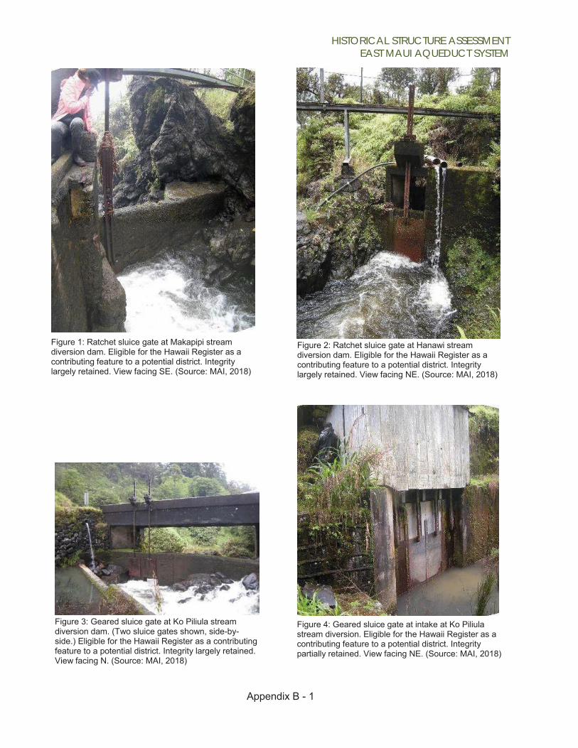
Figure 1: Ratchet sluice gate at Makapipi stream diversion dam. Eligible for the Hawaii Register as a contributing feature to a potential district. Integrity largely retained. View facing SE. (Source: MAI, 2018)
Figure 2: Ratchet sluice gate at Hanawi stream diversion dam. Eligible for the Hawaii Register as a contributing feature to a potential district. Integrity largely retained. View facing NE. (Source: MAI, 2018)
Figure 3: Geared sluice gate at Ko Piliula stream diversion dam. (Two sluice gates shown, side-by- side.) Eligible for the Hawaii Register as a contributing feature to a potential district. Integrity largely retained. View facing N. (Source: MAI, 2018)
Figure 4: Geared sluice gate at intake at Ko Piliula stream diversion. Eligible for the Hawaii Register as a contributing feature to a potential district. Integrity partially retained. View facing NE. (Source: MAI, 2018)

Appendix B - 2
HISTORICAL STRUCTURE ASSESSMENT EAST MAUI AQUEDUCT SYSTEM
Figure 5: Board adjusted sluice gate at intake of Wai O Hue stream diversion. Eligible for the Hawaii Register as a contributing feature to a potential district. Integrity partially retained. View facing S. (Source: MAI, 2018)
Figure 7: Ratchet sluice gate at Na Ili Ili Haele stream diversion dam. Eligible for the Hawaii Register as a contributing feature to a potential district. Integrity largely retained. View facing NW. (Source: MAI, 2018)
Figure 6: Board adjusted sluice gate throw out at intake of Wai O Hue stream diversion. Eligible for the Hawaii Register as a contributing feature to a potential district. Integrity largely retained. View facing SE. (Source: MAI, 2018)
Figure 8: Removed sluice gate (ratchet) at Wailua Nui West stream diversion dam. Eligible for the Hawaii Register as a contributing feature to a potential district. Integrity largely retained. View facing NE. (Source: MAI, 2018)
Appendix B - 3

HISTORICAL STRUCTURE ASSESSMENT EAST MAUI AQUEDUCT SYSTEM
Figure 9: Removed sluice gate (ratchet) at Wailua Nui East stream diversion dam. Eligible for the Hawaii Register as a contributing feature to a potential district. Integrity largely retained. View facing NE. (Source: MAI, 2018)
Figure 11: Board adjusted sluice gate at intake of Wailua Iki West stream diversion. Eligible for the Hawaii Register as a contributing feature to a potential district. Integrity largely retained. View facing NE. (Source: MAI, 2018)
Figure 10: Ratchet sluice gate at Wailua Iki West stream diversion. Eligible for the Hawaii Register as a contributing feature to a potential district. Integrity largely retained. View facing N. (Source: MAI, 2018)
Figure 12: Ratchet sluice gate at Wailua Iki East stream diversion dam. Eligible for the Hawaii Register as a contributing feature to a potential district. Integrity largely retained. View facing NE. (Source: MAI, 2018)
Appendix B - 4

HISTORICAL STRUCTURE ASSESSMENT EAST MAUI AQUEDUCT SYSTEM
Appendix B - 5
Figure 13: Board adjusted sluice gate at intake of Wailua Iki East stream diversion. Eligible for the Hawaii Register as a contributing feature to a potential district. Integrity partially retained. View facing NW. (Source: MAI, 2018)
Figure 15: Ratchet sluice gate at intake at Hoolawa Haiku stream diversion. Eligible for the Hawaii Register as a contributing feature to a potential district. Integrity partially retained. View facing E. (Source: MAI)
Figure 14: Geared sluice gate at Hoolawa Haiku stream diversion dam. Eligible for the Hawaii Register as a contributing feature to a potential district. Integrity partially retained. View facing NW. (Source: MAI, 2018)
Figure 16: Ratchet sluice gate at Banana Intake stream diversion dam. Eligible for the Hawaii Register as a contributing feature to a potential district. Integrity largely retained. View facing NW. (Source: MAI, 2018)

HISTORICAL STRUCTURE ASSESSMENT EAST MAUI AQUEDUCT SYSTEM
A
6
Figure 17: Geared sluice gate at Honomanu stream diversion dam. Eligible for the Hawaii Register as a contributing feature to a potential district. Integrity largely retained. View facing N. (Source: MAI, 2018)
Figure 39: Board adjusted sluice gate at intake of Kolea Power House stream diversion. Eligible for the Hawaii Register as a contributing feature to a potential district. Integrity partially retained. View facing W. (Source: MAI, 2018)
Figure 18: Geared sluice gate at intake at Honomanu stream diversion. Eligible for the Hawaii Register as a contributing feature to a potential district. Integrity largely retained. View facing E. (Source: MAI, 2018)
Figure 20: Ratchet sluice gate throw out at intake of Kolea Power House stream diversion. Eligible for the Hawaii Register as a contributing feature to a potential district. Integrity largely retained. View facing N. (Source: MAI, 2018)
ppendix B -

HISTORICAL STRUCTURE ASSESSMENT EAST MAUI AQUEDUCT SYSTEM
Appendix B - 7
Figure 21: Threaded shaft sluice gate throw out (on left) at intake of Kolea Power House stream diversion. Eligible for the Hawaii Register as a contributing feature to a potential district. Integrity largely retained. View facing N. (Source: MAI, 2018)
Figure 22: Ratchet sluice gate throw out at Kaaiea stream diversion. Eligible for the Hawaii Register as a contributing feature to a potential district. Integrity largely retained. View facing S. (Source: MAI, 2018)
Figure 23: Board adjusted sluice gate (on left) at intake of Hoalua stream diversion. Eligible for the Hawaii Register as a contributing feature to a potential district. Integrity partially retained. View facing NE. (Source: MAI, 2018)
Figure 24: Ratchet sluice gate throw out at intake of Hoalua stream diversion. Eligible for the Hawaii Register as a contributing feature to a potential district. Integrity largely retained. View facing NE. (Source: MAI, 2018)

HISTORICAL STRUCTURE ASSESSMENT EAST MAUI AQUEDUCT SYSTEM
Appendix B - 8
Figure 25: Ratchet sluice gate at Hoolawa Lii Lii stream diversion dam. Eligible for the Hawaii Register as a contributing feature to a potential district. Integrity largely retained. View facing NE. (Source: MAI, 2018)
Figure 26: Ratchet sluice gate throw out at intake of Hoolawa Nui stream diversion. Eligible for the Hawaii Register as a contributing feature to a potential district. Integrity largely retained. View facing S. (Source: MAI, 2018)
Figure 28: Board adjusted sluice gate at Piinaau throw out. Eligible for the Hawaii Register as a contributing feature to a potential district. Integrity partially retained. View facing SW. (Source: MAI, 2018)
Figure 27: Board adjusted throw out sluice gate at Piinaau throw out. Eligible for the Hawaii Register as a contributing feature to a potential district. Integrity largely retained. View facing NE. (Source: MAI, 2018)

HISTORICAL STRUCTURE ASSESSMENT EAST MAUI AQUEDUCT SYSTEM
Appendix B - 9
Figure 29: Ratchet sluice gate at Wai Ka Moi stream diversion dam. Eligible for the Hawaii Register as a contributing feature to a potential district. Integrity largely retained. View facing NW. (Source: MAI, 2018)
Figure 30: Ratchet sluice gate at Kolea stream diversion dam. Eligible for the Hawaii Register as a contributing feature to a potential district. Integrity largely retained. View facing NE. (Source: MAI, 2018)


HISTORICAL STRUCTURE ASSESSMENT EAST MAUI AQUEDUCT SYSTEM
Appendix C - 1
Appendix C
Sketch plans of 20 EMI Aqueduct Stream Diversions with photos of their associated sluice gates

HISTORICAL STRUCTURE ASSESSMENT EAST MAUI AQUEDUCT SYSTEM
Appendix C - 2

HISTORICAL STRUCTURE ASSESSMENT EAST MAUI AQUEDUCT SYSTEM
Appendix C - 3
MAKAPIPI
Ratchet sluice gate at Makapipi stream diversion dam. View facing NE. Source: MAI, 2018

HISTORICAL STRUCTURE ASSESSMENT EAST MAUI AQUEDUCT SYSTEM
Appendix C - 4
HANAWI
Ratchet sluice gate at Hanawi stream diversion dam. View facing SE.

Appendix C - 5
HISTORICAL STRUCTURE ASSESSMENT EAST MAUI AQUEDUCT SYSTEM
KO PILIULA
Geared sluice gate at intake at Ko Piliula stream diversion DAM. View facing N.
Geared sluice gate at intake at Ko Piliula stream diversion. View facing NE.

Appendix C - 6
HISTORICAL STRUCTURE ASSESSMENT EAST MAUI AQUEDUCT SYSTEM
WAI O HUE
Board adjusted sluice gate throw-out at intake of Wai O Hue stream diversion. View facing SE.
Board adjusted sluice gate at intake of Wai O Hue stream diversion. View facing S.

Appendix C - 7
HISTORICAL STRUCTURE ASSESSMENT EAST MAUI AQUEDUCT SYSTEM
NA ILI ILI HA ELE
Ratchet sluice gate at Hanawi stream diversion dam. View facing SE.

Appendix C - 8
HISTORICAL STRUCTURE ASSESSMENT EAST MAUI AQUEDUCT SYSTEM
WAILUA NUI WEST
Removed sluice gate (ratchet) at Wailua Nui West stream diversion dam. View facing NE.

Appendix C - 9
HISTORICAL STRUCTURE ASSESSMENT EAST MAUI AQUEDUCT SYSTEM
WAILUA NUI EAST
Removed sluice gate (ratchet) at Wailua Nui East stream diversion dam. View facing NE.

HISTORICAL STRUCTURE ASSESSMENT EAST MAUI AQUEDUCT SYSTEM
Appendix C - 10
WAILUA IKI WEST
Ratchet sluice gate at Wailua Iki West stream diversion. View facing N.

Appendix C - 11
HISTORICAL STRUCTURE ASSESSMENT EAST MAUI AQUEDUCT SYSTEM
WAILUA IKI EAST
Ratchet sluice gate at Wailua Iki East stream diversion dam. View facing NE.
oard djusted luice gate t intake of ailua Iki ast stream iversion. iew facing W.
B a s a W E d V N

HISTORICAL STRUCTURE ASSESSMENT EAST MAUI AQUEDUCT SYSTEM
Appendix C - 12
HOOLAWA HAIKU
eared sluice ate at oolawa aiku stream iversion dam.
Gg H H d

Appendix C - 13
HISTORICAL STRUCTURE ASSESSMENT EAST MAUI AQUEDUCT SYSTEM
BANANA INTAKE
Ratchet sluice gate at Banana Intake stream diversion dam. View facing NW.

Appendix C - 14
HISTORICAL STRUCTURE ASSESSMENT EAST MAUI AQUEDUCT SYSTEM
HONOMANU
Geared sluice gate at Honomanu stream diversion dam. View facing N.
Geared sluice gate at intake at Honomanu stream diversion. View facing E.

Appendix C - 15
HISTORICAL STRUCTURE ASSESSMENT EAST MAUI AQUEDUCT SYSTEM
KOLEA POWER HOUSE
Board adjusted sluice gate at intake of Kolea Power House stream diversion. View facing W.
Ratchet sluice gate throw-out (on right) and threaded shaft sluice gate throw-out (on left) at intake of Kolea Power House stream diversion. View facing N.

Appendix C - 16
HISTORICAL STRUCTURE ASSESSMENT EAST MAUI AQUEDUCT SYSTEM
KAAIEA
Ratchet sluice gate throw-out at Kaaiea stream diversion. View facing S

Appendix C - 17
HISTORICAL STRUCTURE ASSESSMENT EAST MAUI AQUEDUCT SYSTEM
HOALUA
Board adjusted sluice gate (on left) at intake of Hoalua stream diversion. View facing NE.

Appendix C - 18
HISTORICAL STRUCTURE ASSESSMENT EAST MAUI AQUEDUCT SYSTEM
HOOLAWA LII LII
Ratchet sluice gate at Hoolawa Lii Lii stream diversion dam. View facing NE.

Appendix C - 19
HISTORICAL STRUCTURE ASSESSMENT EAST MAUI AQUEDUCT SYSTEM
HOOLAWA NUI
Ratchet sluice gate throw-out at intake of Hoolawa Nui stream diversion. View facing S.

HISTORICAL STRUCTURE ASSESSMENT EAST MAUI AQUEDUCT SYSTEM
PII NAAU
Appendix C - 20
Board adjusted throw-out sluice gate at Piinaau throw-out. View facing NE.
Ratchet sluice gate throw-out at intake of Hoolawa Nui stream diversion. View facing S.

HISTORICAL STRUCTURE ASSESSMENT EAST MAUI AQUEDUCT SYSTEM
Appendix C - 21
WAI KA MOI
Ratchet sluice gate at Wai Ka Moi stream diversion dam. View facing NW.

HISTORICAL STRUCTURE ASSESSMENT EAST MAUI AQUEDUCT SYSTEM
KOLEA
Appendix C - 22
Ratchet sluice gate at Kolea stream diversion dam. View facing NE.

HISTORICAL STRUCTURE ASSESSMENT EAST MAUI AQUEDUCT SYSTEM
Appendix D - 1
Appendix D Table 3: Basis for Estimated Dates of Construction
# Feature Name Ditch Estimated year built
Year built date based on
001 Makapipi Koolau 1904 Date of ditch constriction, appearance of concrete and masonry work 002 Hanawi Koolau 1904 Date of ditch constriction, appearance of concrete and masonry work
003
Ko Piliula West
Koolau
1914
Date of adjacent Hana Highway bridge construction, diversion uses bridge abutments.
004 Wai o Hue Koolau pre 1960 Appearance of concrete and masonry work. 005 Na ili ili Haele Lowrie 1920s Date of nearby Hana Highway construction. 006 Wailua Nui West Koolau 1923 Date of nearby bridge construction on ditch trail. 007 Wailua Nui East Koolau 1923-24 Date of nearby bridge construction on ditch trail. 008 Wailua Iki West Koolau 1923-24 Date of nearby bridge construction on ditch trail. 009 Wailua Iki East Koolau 1923-24 Date of nearby bridge construction on ditch trail. 010 Hoolawa Haiku Haiku 1923 Date of USGS benchmark on bridge, diversion uses bridge abutments. 011 Banana Intake Spreckles 1924 Date of adjacent bridge construction, diversion uses bridge abutments. 012 Main Honomanu Spreckles 1923-24 Date of nearby bridge construction on ditch trail. 013 Kolea Power House Koolau pre 1960 Appearance of concrete and masonry work. 014 Kaaiea Center 1928 Date of adjacent Hana Highway bridge construction. 015 Hoalua Lowrie 1929 Date of adjacent Hana Highway bridge construction. 016 Hoolawa Lii Lii Lowrie pre 1960 Appearance of concrete and masonry work. 017 Hoolawa Nui Lowrie pre 1960 Appearance of concrete and masonry work. 018 Pii Naau Koolau pre 1960 Appearance of concrete and masonry work. 019 Wai Kamoi Center pre 1960 Appearance of concrete and masonry work. 020 Kolea Center pre 1960 Appearance of concrete and masonry work.