APPENDIX K - ci.lacey.wa.us · SIEMENS FDK: 001SPCAB: FLOW TRANSMITTER REMOTE MOUNT BRACKETS...
33
APPENDIX K
Transcript of APPENDIX K - ci.lacey.wa.us · SIEMENS FDK: 001SPCAB: FLOW TRANSMITTER REMOTE MOUNT BRACKETS...

APPENDIX K

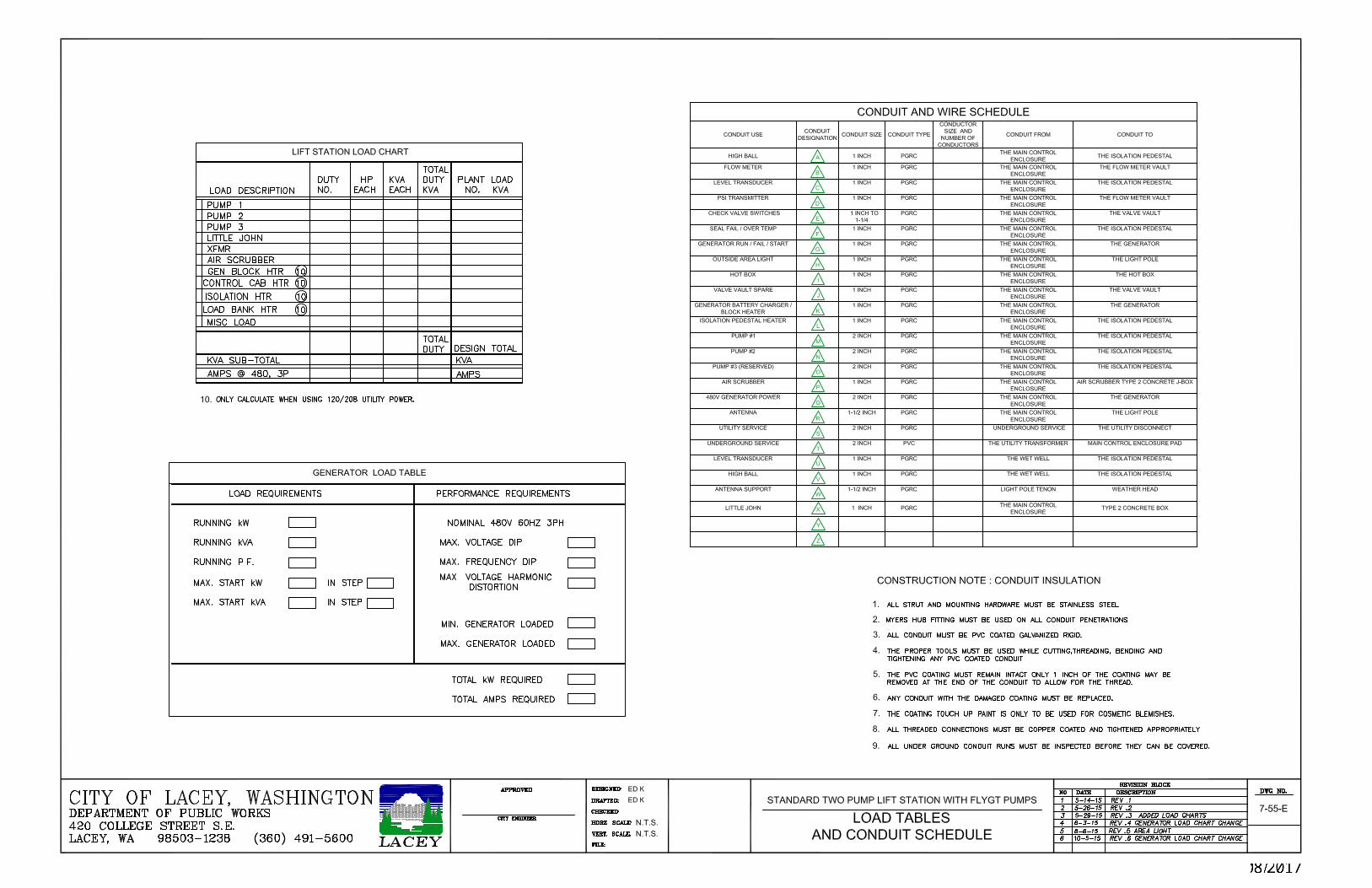
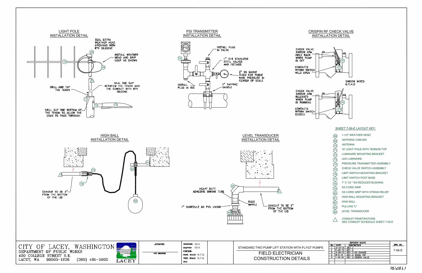
Lift Station Electrical Control Package
APPENDIX K
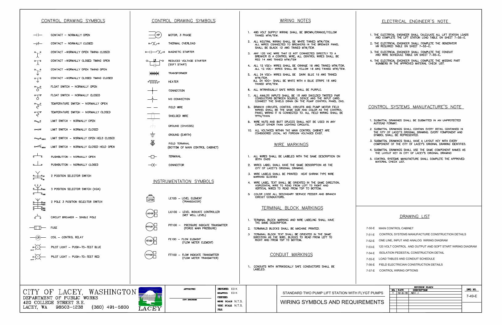
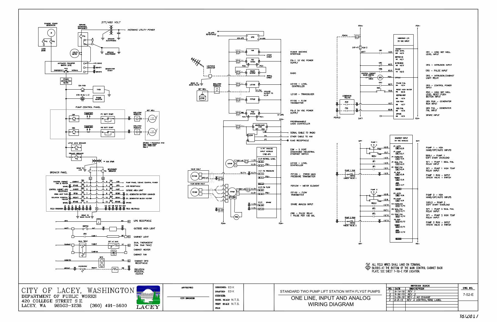
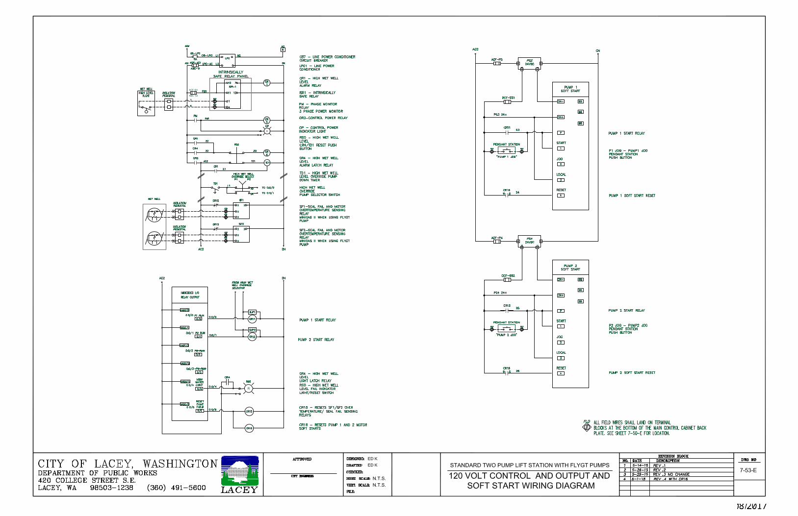
K 2-10 Electrical Drawings 7-49-E thru 7-57-E Color (11X17)
K 11-20 Approved Materials Checklist
K 21-22 Labeling Document
K 24-32 Electrical Drawings 7-49-E thru 7-57-E B&W (11X17)
Electrical Drawings 7-49-E thru 7-57-E (24X36) are available upon request
Ekeyt
Text Box
K - 1
Ekeyt
Text Box
08/2017
Ekeyt
Text Box
K - 2
Ekeyt
Text Box
08/2017

Ekeyt
Text Box
K - 3
Ekeyt
Text Box
08/2017

Ekeyt
Text Box
K - 4
Ekeyt
Text Box
08/2017
Ekeyt
Text Box
K - 5
Ekeyt
Text Box
08/2017
Ekeyt
Text Box
K - 6
Ekeyt
Text Box
08/2017

Ekeyt
Text Box
K - 7
Ekeyt
Text Box
08/2017
Ekeyt
Text Box
K - 8
Ekeyt
Text Box
08/2017
Ekeyt
Text Box
K - 9
Ekeyt
Text Box
08/2017

Ekeyt
Text Box
K - 10
Ekeyt
Text Box
08/2017

APPROVED MATERIALS (BOM)
*Engineer to determine part number based on voltage/amperageand fill in the missing part number represented by *the asterisk.
SPECIAL CONSTRUCTION NOTES ENGINEER ITEM CITY OF LACEY DESCRIPTION MANUFACTURER PART # SPECIFIED PART#
(see foot note)
RADIO EQUIPMENT
DATA RADIO CALAMP INTEGRA TR 242-4048-***
PLC TO RADIO SERIAL CABLE "CUSTOM" ALLEN BRADLEY 1761-CBL-PM02 The 9 pin end must be re-pinned to null modem configuration. No Adapter! SEE DETAIL SHEET 7-57-E
RADIO TO ARRESTOR COAX JUMPER "CUSTOM" "SMA" type male to "N" type male
LIGHTENING ARRESTOR POLYPHASER IS-B50LN-C2 Bond to ATS with #8 AWG CU wire.
RADIO BRACKET “CUSTOM” Allow minimum 1" clearance above and below the radio and flush with the front of the Pump Control Panel.
ETHERNET PORT EATON M22-RJ45-SA
CABINET LIGHT COOPER HU1024D830P
24" DAISY CHAIN CONNECTOR COOPER HU103P
120" DAISY CHAIN CONNECTOR COOPER HU104P Cut connector off of one end and land under CR2.
TVSS GENERAL ELECTRIC 9L15ECC001 Mount TVSS to the back plate.
INTRUSION SWITCH ASSEMBLY
RECEPTACLE EATON E50RA
SWITCH BODY EATON E50SA
5° HEAD EATON E50DR1
LEVER ARM EATON E50KL538
CABINET VENTILATION
FAN RITTAL 3239.110 Mount fan on lower right.
VENT RITTAL 3239.200
SS HOOD RITTAL 3239.080
*Control System Manufacturing shall use listed parts and install them using the Special Construction Notes.
Mount intake and exhaust hoods forward in the Main Control Cabinet toward the door, allowing clearance for the Service Entrance Disconnect. Filter must be installed.
Mount intrusion switch to Main Control Cabinet ceiling track with a bracket. Intrusion switch is configured normally closed held open. When the control cabinet door is closed, the lever switch arm is pushed back and the contacts within the switch are held open. When the control cabinet door is opened, the lever arm is released and contacts within the switch close. At this point CR2 is energized. CR2 has two C–form contacts (two poles). One pole switches the cabinet light via the normally open contacts the other pole switches the intrusion input via normally closed contacts. The PLC program creates an intrusion alarm when there is no input to I:0/2. WHEN THE MAIN CONTROL CABINET IS CLOSED, THERE IS AN INPUT TO I:0/2.
6
5
3
4
2
1
Ekeyt
Text Box
K - 11
Ekeyt
Text Box
08/2017
APPROVED MATERIALS (BOM)
*Engineer to determine part number based on voltage/amperageand fill in the missing part number represented by *the asterisk.
SPECIAL CONSTRUCTION NOTES ENGINEER ITEM CITY OF LACEY DESCRIPTION MANUFACTURER PART # SPECIFIED PART#
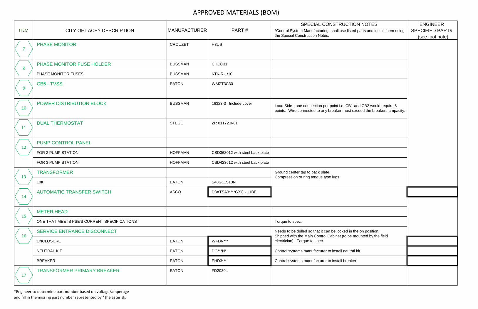
(see foot note)PHASE MONITOR CROUZET H3US
PHASE MONITOR FUSE HOLDER BUSSMAN CHCC31
PHASE MONITOR FUSES BUSSMAN KTK-R-1/10
CB5 - TVSS EATON WMZT3C30
POWER DISTRIBUTION BLOCK BUSSMAN 16323-3 Include cover
DUAL THERMOSTAT STEGO ZR 01172.0-01
PUMP CONTROL PANEL
FOR 2 PUMP STATION HOFFMAN CSD363012 with steel back plate
FOR 3 PUMP STATION HOFFMAN CSD423612 with steel back plate
TRANSFORMER
10K EATON S48G11S10N
AUTOMATIC TRANSFER SWITCH ASCO D3ATSA3****GXC - 11BE
METER HEAD
ONE THAT MEETS PSE'S CURRENT SPECIFICATIONS Torque to spec.
SERVICE ENTRANCE DISCONNECT
ENCLOSURE EATON WFDN***
NEUTRAL KIT EATON DG***N* Control systems manufacturer to install neutral kit.
BREAKER EATON EHD3*** Control systems manufacturer to install breaker.
TRANSFORMER PRIMARY BREAKER EATON FD2030L
Load Side - one connection per point i.e. CB1 and CB2 would require 6 points. Wire connected to any breaker must exceed the breakers ampacity.
*Control System Manufacturing shall use listed parts and install them using the Special Construction Notes.
Ground center tap to back plate. Compression or ring tongue type lugs.
Needs to be drilled so that it can be locked in the on position. Shipped with the Main Control Cabinet (to be mounted by the field electrician). Torque to spec.
10
8
9
7
11
12
13
14
15
16
17
Ekeyt
Text Box
K - 12
Ekeyt
Text Box
08/2017

APPROVED MATERIALS (BOM)
*Engineer to determine part number based on voltage/amperageand fill in the missing part number represented by *the asterisk.
SPECIAL CONSTRUCTION NOTES ENGINEER ITEM CITY OF LACEY DESCRIPTION MANUFACTURER PART # SPECIFIED PART#
(see foot note)
TRANSFORMER SECONDARY BREAKER EATON EHD205OL
LEVEL CONTROL
LUT 420 SIEMENS 7ML50500AA111DA0
UPS APC SMT1500
UPS EATON 5115 1400
BREAKER PANEL EATON CH12L125R
INTRINSICALLY SAFE RELAY PANEL ENCLOSURE HOFFMAN A12N106 with white steel back plate
FLOW METER
MAG 5100 ELEMENT and MAG 6000 TRANSMITTER SIEMENS 7ME6580***142 1JA2
COIL CABLE SIEMENS FDK: 001STCAB
EMPTY PIPE CABLE SIEMENS FDK: 001SPCAB
FLOW TRANSMITTER REMOTE MOUNT BRACKETS SIEMENS FDK: 085U1053
GROUNDING RINGS SIEMENS TGX:001F0*** Grounding rings are required for all installations.
POTTING KIT SIEMENS FDK: 085U0220
UPS RECEPTACLE PHOENIX 2963860
GFCI HUBBELL DRUBGFI15 DGK
All wires shall be tinned stranded MTW/AWM/TEW. NO VINYL COVERING. Wires connected to breakers will be black #12 . All 120 VAC control wires are to be red #14. All 120 VAC neutrals will be white. One neutral and ground for each branch circuit.
Barrier to be outlined with red tape on the bottom of the Main Control Cabinet prior to shipping. Knock out a 1" penetration centered in the bottom of the ISR panel.
*Control System Manufacturing shall use listed parts and install them using the Special Construction Notes.
18
19
20
20
21
22
23
24
25
Ekeyt
Text Box
K - 13
Ekeyt
Text Box
08/2017

APPROVED MATERIALS (BOM)
*Engineer to determine part number based on voltage/amperageand fill in the missing part number represented by *the asterisk.
SPECIAL CONSTRUCTION NOTES ENGINEER ITEM CITY OF LACEY DESCRIPTION MANUFACTURER PART # SPECIFIED PART#
(see foot note)
OUTSIDE AREA LIGHT SWITCH BRYANT CSB120BW
BELL BOX COOPER TP7010
COVER BRYANT SS1
CABINET HEATER HOFFMAN DHA2001A
PANELVIEW HMI ALLEN BRADLEY 2711P - T7C4A8
AMMETER
2 1/2 " PC&S ST70
MOTOR CIRCUIT BREAKER THRU - DOOR OPERATOR EATON EHMVD - 12R
H–O–A SWITCH
22 MM HW SERIES CONTACT BLOCKS IDEC HW - F**
CONTROL POWER INDICATOR
22 MM HW SERIES LED LAMP IDEC LST - H2*
FULL VOLTAGE ADAPTER IDEC HW-DA1F
BLUE LENS IDEC HW1A - L1 – S
CONTACT BLOCKS IDEC HW - F**
OPERATOR IDEC HW1B - ****
HIGH WET WELL OVERRIDE SELECTOR SWITCH
22 MM HW SERIES CONTACT BLOCKS IDEC HW - F**
OPERATOR IDEC HW1S - *T
*Control System Manufacturing shall use listed parts and install them using the Special Construction Notes.
Scaled to read the pumps running amps in the center of the scale .i.e. If the pump is designed to run at 10 amps, the meter should be scaled 1–20 amps.
Clocked straight up and down for the "ON" position. Mount Breaker and Operator independently, so the Operator can be removed and the Breaker remains mounted on the back plate. Operator Rod needs to be cut to the proper length. Install Cotter Pins.
26
27
28
29
30
31
32
33
Ekeyt
Text Box
K - 14
Ekeyt
Text Box
08/2017

APPROVED MATERIALS (BOM)
*Engineer to determine part number based on voltage/amperageand fill in the missing part number represented by *the asterisk.
SPECIAL CONSTRUCTION NOTES ENGINEER ITEM CITY OF LACEY DESCRIPTION MANUFACTURER PART # SPECIFIED PART#
(see foot note)
HIGH WET WELL LEVEL INDICATOR/RESET SWITCH
22 MM HW SERIES LED LAMP IDEC LST - H2*
FULL VOLTAGE ADAPTER IDEC HW-DA1F
RED LENS IDEC HW1A - L1 – R
CONTACT BLOCKS IDEC HW - F**
OPERATOR IDEC HW1B - ****
UPS SHELF “CUSTOM”
MOTOR CIRCUIT BREAKER EATON HMCPE*** Wire connected to any breaker must exceed the breakers ampacity.
CURRENT TRANSFORMER CROMPTON 2RL-*** Paired with the Ammeter, may need to wrap CT to achieve an accurate current reading.
SOFT START EATON S8-11 *****
AIR SCRUBBER BREAKER EATON HMCPE**
ON/OFF HASPLOCK - 3 POLE EATON EFPHL
LITTLE JOHN BREAKER EATON HMCPE**
ON/OFF HASPLOCK - 3 POLE EATON EFPHL
CB7 - LINE POWER CONDITIONER EATON FAZ-C5/1-NA
AC FUSE HOLDERS
NEON FUSE BLOWN INDICATOR SPRECHER SCHUH V7-H4
AC FUSES BUSSMAN GDL - **/KLM - **/ABC - **
*Control System Manufacturing shall use listed parts and install them using the Special Construction Notes.
Set to limiting current start mode. Set fault reset to auto. Wire connected to the soft start must exceed the breakers ampacity.
The shelf needs to be heavy enough to support the weight of the UPS and larger than the UPS base. For earthquake readiness, the UPS must also be strapped to the Main Control Cabinet back plate.
34
35
36
37
38
39
40
41
42
Ekeyt
Text Box
K - 15
Ekeyt
Text Box
08/2017

APPROVED MATERIALS (BOM)
*Engineer to determine part number based on voltage/amperageand fill in the missing part number represented by *the asterisk.
SPECIAL CONSTRUCTION NOTES ENGINEER ITEM CITY OF LACEY DESCRIPTION MANUFACTURER PART # SPECIFIED PART#
(see foot note)
DC FUSE HOLDERS
LED FUSE BLOWN INDICATOR SPRECHER SCHUH V7-H5
DC FUSES BUSSMAN ABC - **/KLM - **
12 VDC POWER SUPPLY SOLA SDP3 - 15 - 100T
24 VDC POWER SUPPLY SOLA SDP4 - 24 - 100LT
24 VDC SOFT START POWER SUPPLY EATON PSG240E
PROGRAMMABLE LOGIC CONTROLLER AND I/O Allow 2" clearance per manufacturer requirements.
MICROLOGIX 1100 ALLEN BRADLEY 1763-L16DWD
ANALOG INPUT MODULE ALLEN BRADLEY 1762-IF4
DIGITAL INPUT MODULE ALLEN BRADLEY 1762-IQ16
ETHERNET SWITCH N-TRON 105TX-SL
CONTROL RELAYS IDEC RH*B-UL
RELAY BASE IDEC SH*B-05
PULSE RELAY CR5 ALLEN BRADLEY 700-HLS1Z24
LINE POWER CONDITIONER ALLEN BRADLEY 4983-DC120-05 Allow 1" clearance per manufacturer requirements.
TIME DELAY RELAY CROUZET OUR1 Set on “C” off delay.
RELAY BASE IDEC SR2P - 06
Pulse wires shall be tinned stranded MTW/AWM/TEW. NO VINYL COVERING. Positive - Dark blue #16 Negative - White with blue stripe #16
*Control System Manufacturing shall use listed parts and install them using the Special Construction Notes.
Allow 1" clearance per manufacturer requirements. All wires shall be tinned stranded MTW/AWM/TEW. NO VINYL COVERING. 12 VDC Positive - Orange #16 12 VDC Negative - Yellow #16 Allow 1" clearance per manufacturer requirements. All wires shall be tinned stranded MTW/AWM/TEW. NO VINYL COVERING. 24 VDC Positive - Dark blue #16 24 VDC Negative - White with blue stripe #16Allow 50 mm clearance top and bottom, 20 mm on the sides, per manufacturer requirements. All wires shall be tinned stranded MTW/AWM/TEW. NO VINYL COVERING. 24 VDC Positive - Dark blue #16 24 VDC Negative - White with blue stripe #16
43
44
45
46
47
48
49
50
51
52
Ekeyt
Text Box
K - 16
Ekeyt
Text Box
08/2017

APPROVED MATERIALS (BOM)
*Engineer to determine part number based on voltage/amperageand fill in the missing part number represented by *the asterisk.
SPECIAL CONSTRUCTION NOTES ENGINEER ITEM CITY OF LACEY DESCRIPTION MANUFACTURER PART # SPECIFIED PART#
(see foot note)
SEAL FAIL / OVER TEMP RELAY
FOR FLYGT PUMPS MINICAS II Set on manual reset.
FOR NON FLYGT PUMPS MTS #MOS-1P Ground pin 4. Run blue wire from pin 4 to field terminal. Set on manual reset.
TERMINAL BLOCKS SPRECHER SCHUH V7-W4 SERIES Steel Din Rail (NO Aluminum). Stops installed.
MAIN CONTROL CABINET ENCLOSURE HOFFMAN A727224USSLP-MOD with white steel back plate
ISOLATION PEDESTAL ENCLOSURE
FOR 2 PUMP STATION HOFFMAN A30H2412SS6LP3PT with white steel back plate SEE DETAIL SHEET 7-51-E AND 7-54-E
FOR 3 PUMP STATION HOFFMAN A36H3612SS6LP3PT with white steel back plate SEE DETAIL SHEET 7-51-E AND 7-54-E
CABLE SEAL
LIQUID POUR RESIN BARRIER APPLETON PXSS2K SERIES
PUMP POWER RECEPTACLE
DE-CONTACTOR TYPE MELTRIC D**** Pumps with separate cords for seal fail/over temp also use PN7C 63-034043 receptacle. SEE DETAIL SHEET 7-54-E
PUMP CORD CONNECTOR
DE-CONTACTOR TYPE MELTRIC D**** with NPT HANDLE
ISOLATION PEDESTAL BARRIER “CUSTOM” Constructed of aluminum and needs to run the full height of the panel and extend 6 inches towards the door from the back plate.
ISOLATION PEDESTAL HEATER PFANNENBERG 17015005007
ISOLATION PEDESTAL HYGROSTAT STEGO MFR012
INTRINSICALLY SAFE RELAY TURCK IM1-22EX-R
Pumps with separate cords for seal fail/over temp also use PN7C 01-NA013-12 connector. Use with 1/2" NPT poly handle 63-38043. SEE DETAIL SHEET 7-54-E
*Control System Manufacturing shall use listed parts and install them using the Special Construction Notes.
Factory installed Drip Shield and drain holes in the enclosure bottom per (UL 3R). No penetrations in the top. Padlocking handle. Accessories to be spot welded: Door stop kit - Bottom, both doors (see modification services guide). Folding 12" x 12" Shelf - ACSHLF1212SS. Default location: Inside left door.
53
54
55
56
57
58
59
60
61
62
63
Ekeyt
Text Box
K - 17
Ekeyt
Text Box
08/2017

APPROVED MATERIALS (BOM)
*Engineer to determine part number based on voltage/amperageand fill in the missing part number represented by *the asterisk.
SPECIAL CONSTRUCTION NOTES ENGINEER ITEM CITY OF LACEY DESCRIPTION MANUFACTURER PART # SPECIFIED PART#
(see foot note)
BREAKER PANEL BREAKER – 15A EATON CH115
BREAKER PANEL BREAKER – 20A EATON CH120
PUMP JOG PENDANT
FOR 2 PUMP STATION WOODHEAD 4022
FOR 3 PUMP STATION WOODHEAD 4023
ISOLATION PEDESTAL POST BASE B-LINE B281SQ SS4 SEE DETAIL SHEET 7-54-E
UNISTRUT P2073ASQSS SEE DETAIL SHEET 7-54-E
1 ½” WEATHER HEAD OZ-GEDNEY 170-150G SEE DETAIL SHEET 7-56-E
ANTENNA CABLING
LMR400 with type "N" male LMR400 connector
ANTENNA
Laird UHF Directional Yagi ANTENEX 4506 SEE DETAIL SHEET 7-56-E
16’ LIGHT POLE WITH TENNON TOP HAPCO RTA16D6B4200BAL/AB
LUMINAIRE ARM CREE XA-XSP4PTMNT Mount with stainless steel hardware. SEE DETAIL SHEET 7-56-E
LED LUMINAIRE CREE BXSPBHT3MEB40KUS ULBKJ SEE DETAIL SHEET 7-56-E
PRESSURE TRANSMITTER ASSEMBLY
SITRANS P DS III PRESSURE TRANSMITTER SIEMENS 7MF4033-1DA10-1NC6-B21 Instrument to be calibrated for Full scale output (20 mA) at 100 PSIG. SEE DETAIL SHEET 7-56-E
DIAPHRAM SEAL WIKA L990.10.N4FXN8F.SS.SS-2.SS.SS.BN1500PLG
The diaphragm seal is to be filled with glycol and mounted to the pressure transmitter as an assembly at the instrumentation shop.
50 foot cord needs to be supplied with pendant attached and then cut to length in the filed. Cord needs to be long enough to reach the wet well from the main control cabinet. Neatly coil up cord and hag up by using a heavy duty Velcro strap with a eyelet in it to secure to an existing bolt.
Must be taped with silicone splicing tape and covered with black vinyl tape. NO HEAT SHRINK. SEE DETAIL SHEET 7-56-E
Ground inside the hand hole. Grout under bottom of pole. SEE DETAIL SHEET 7-56-E
*Control System Manufacturing shall use listed parts and install them using the Special Construction Notes.
64
65
66
67
68
69
70
71
72
73
74
Ekeyt
Text Box
K - 18
Ekeyt
Text Box
08/2017

APPROVED MATERIALS (BOM)
*Engineer to determine part number based on voltage/amperageand fill in the missing part number represented by *the asterisk.
SPECIAL CONSTRUCTION NOTES ENGINEER ITEM CITY OF LACEY DESCRIPTION MANUFACTURER PART # SPECIFIED PART#
(see foot note)
CHECK VALVE SWITCH ASSEMBLY No splices in the J-box. All wires to be home run to the Main Control Cabinet field terminals.
RECEPTACLE EATON E50RA SEE DETAIL SHEET 7-56-E
SWITCH BODY EATON E50SA SEE DETAIL SHEET 7-56-E
5° HEAD EATON E50DR1 SEE DETAIL SHEET 7-56-E
LEVER ARM EATON E50KL537 SEE DETAIL SHEET 7-56-E
LIMIT SWITCH MOUNTING BRACKET
FOR CRISPIN VALVE USE BRACKET CRISPIN P0611FRFVI-13-2 and PA111FRFVI-18-2
Item 75 & 76 included Crispin valve # BDS0A24RF*1-VI-LM-CHR-SP and Crispin valve # BDS0A24RF*1-VI-LM-CHL-SP
NOT USED WITH CRISPIN VALVE “CUSTOM”
LIMIT SWITCH POST BASE B-LINE B280SQ SS4 SEE DETAIL SHEET 7-57-E
POWER STRUT P2072ASQSS SEE DETAIL SHEET 7-57-E
1” X 1/2” SS REDUCER BUSHING CROUSE – HIND RBSS31 SEE DETAIL SHEET 7-56-E
SS CORD GRIP WOODHEAD MAX - LOC 1300980070 SEE DETAIL SHEET 7-56-E
SS CORD GRIP WITH STRAIN RELIEF WOODHEAD MAX – LOC 130097 – 034 SEE DETAIL SHEET 7-56-E
HIGH LEVEL FLOAT (HIGH BALL) MOUNTING BRACKET ANCHOR SCIENTIFIC W-MS SEE DETAIL SHEET 7-56-E
HIGH LEVEL FLOAT (HIGH BALL) ANCHOR SCIENTIFIC
ROTO-FLOAT N.O. type “S” ** foot SEE DETAIL SHEET 7-56-E
PVC COATED CAPPED ELL OCAL LBY35-G Apply copper coat to cap threads. SEE DETAIL SHEET 7-56-E
LEVEL TRANSDUCER SIEMENS XPS–15 7ML11180EA30 Cable will loop through the Isolation Pedestal and home run to Level Control. Do not remove the sheathing. Seal cable gland directly to sheathing with resin. SEE DETAIL SHEET 7-56-E
Needs to be constructed out of 1/4" x 1 1/2" x 8" stainless steel flat bar. Drill and tap holes to mount the limit switch to the flat bar and secure to strut with strut nuts. SEE DETAIL SHEET 7-57-E
*Control System Manufacturing shall use listed parts and install them using the Special Construction Notes.
75
76
77
78
79
80
81
82
83
84
Ekeyt
Text Box
K - 19
Ekeyt
Text Box
08/2017

APPROVED MATERIALS (BOM)
*Engineer to determine part number based on voltage/amperageand fill in the missing part number represented by *the asterisk.
SPECIAL CONSTRUCTION NOTES ENGINEER ITEM CITY OF LACEY DESCRIPTION MANUFACTURER PART # SPECIFIED PART#
(see foot note)
LITTLE JOHN DIGESTER DO2E LJD1001-**
AIR SCRUBBER PURE AIR DS300 with Mist & Grease Eliminator Must be converted to 2 wire control to automatically re - start after a power
fail. SEE DETAIL SHEET 7-56-E
Must be converted to 2 wire control to automatically re - start after a power fail. SEE DETAIL SHEET 7-56-E
*Control System Manufacturing shall use listed parts and install them using the Special Construction Notes.
85
86
Ekeyt
Text Box
K - 20
Ekeyt
Text Box
08/2017

Phenolic Legends 1-1/2” X 7-1/2” Red background with white 3/8” letters, text to include:
4-1/2” X 7-1/2” Black background with white 1/4” letters, text to include:
1-1/2” X 7-1/2” Black background with white 3/16” letters, text to include:
1-1/2” X 6” Black background with white 1/2” letters, text to include:
<1>
<2>
<3> <4>
1-1/2" X 5” Red background with white 1/4” letters, text to include:
1-1/2” X 5” Black background with white 3/8” letters, text to include:
1-1/2” X 6” Black background with white 3/8” letters, text to include:
3/4” X 2-1/2” Black background with white 3/8” letters, text to include:
<5> <6> BREAKER PANEL <7> <8>
3/4” X 2-1/2” Black background with white 3/8” letters, text to include:
3/4” X 2-1/2” Black background with white 3/8” letters, text to include:
1-3/4” X 2” Black background with white 5/32” letters, text to include:
1-3/4” X 2” Black background with white 5/32” letters, text to include:
<9> <10> <12> <13>
1-3/4” X 2” Black background with white 5/32” letters, text to include:
1-3/4” X 2” Black background with white 5/32” letters, text to include:
1-3/4” X 2” Black background with white 5/32” letters, text to include:
3/4” X 3” Black background with white 3/16” letters, phenolic width to match HOA width, text to include:
<13> <14> <15> <16>
3/4” X 3” Black background with white 3/16” letters, phenolic width to match HOA width, text to include:
3/4” X 3” Black background with white 3/16” letters, phenolic width to match HOA width, text to include:
1-1/2" X 5” Black background with white 3/8” letters, text to include:
1-1/2" X 5” Black background with white 3/8” letters, text to include:
<17> <18> <19> <20>
1-1/2" X 5” Black background with white 3/8” letters, text to include:
1-1/2" X 5” Red background with white 3/16” letters, text to include:
1-1/2" X 5” Black background with white 3/8” letters, text to include:
<21> <22> <23>
277/480 3ø *** AMPS SERVICE/METER DISCONNECT FEEDS ATS IN CONTROL CABINET
FED BY STANDBY GENERATOR (location of generator)
LIFT STATION (address) LIFT STATION (number)
DISCONNECT TO THE RIGHT OF ENCLOSURE
BREAKER PANEL PUMP CONTROL PANEL
CONTROL POWER
PUMP 1
PUMP 2
PUMP 3
HIGH WET WELL
OVERRIDE SELECT
P1 P2
HIGH WET WELL
OVERRIDE SELECT
P1 P2 P3
HIGH WET WELL
LEVEL RESET
HAND-OFF-AUTO PUMP 1
PUMP 2 PUMP 3 LITLLE JOHN ISR PANEL
ISOLATION PEDESTAL GENERATOR EMERGENCY STOP INSIDE
AIR SCRUBBER
Ekeyt
Text Box
K - 21
Ekeyt
Text Box
08/2017
480 VOLTS
DANGER
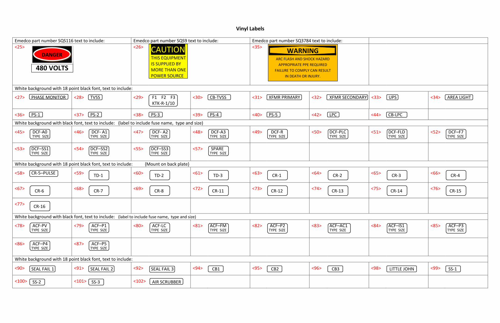
Vinyl Labels Emedco part number SQS116 text to include: Emedco part number SQS9 text to include: Emedco part number SQ3784 text to include: <25> <26> CAUTION
THIS EQUIPMENT IS SUPPLIED BY MORE THAN ONE POWER SOURCE
<35>
White background with 18 point black font, text to include: <27> PHASE MONITOR <28> TVSS <29> F1 F2 F3
KTK-R-1/10 <30> CB-TVSS
<31> XFMR PRIMARY <32> XFMR SECONDARY <33> UPS <34> AREA LIGHT
<36> PS-1 <37> PS-2 <38> PS-3 <39> PS-4 <40> PS-5 <42> LPC <44> CB-LPC
White background with black font, text to include: (label to include fuse name, type and size) <45> DCF-A0
TYPE SIZE
<46> DCF- A1 TYPE SIZE
<47> DCF- A2 TYPE SIZE
<48> DCF-A3 TYPE SIZE
<49> DCF-R TYPE SIZE
<50> DCF-PLC TYPE SIZE
<51> DCF-FLD TYPE SIZE
<52> DCF–F7 TYPE SIZE
<53> DCF–SS1
TYPE SIZE
<54> DCF–SS2 TYPE SIZE
<55> DCF–SS3 TYPE SIZE
<57> SPARE TYPE SIZE
White background with 18 point black font, text to include: {Mount on back plate} <58> CR-5–PULSE <59> TD-1
<60> TD-2
<61> TD-3
<63> CR-1
<64> CR-2
<65> CR-3
<66> CR-4
<67> CR-6
<68> CR-7
<69> CR-8
<72> CR-11
<73> CR-12
<74> CR-13
<75> CR-14
<76> CR-15
<77> CR-16
White background with black font, text to include: (label to include fuse name, type and size) <78> ACF-PV
TYPE SIZE
<79> ACF–P1 TYPE SIZE
<80> ACF-LC TYPE SIZE
<81> ACF–FM TYPE SIZE
<82> ACF–P2 TYPE SIZE
<83> ACF–AC1 TYPE SIZE
<84> ACF–IS1 TYPE SIZE
<85> ACF–P3 TYPE SIZE
<86> ACF–P4
TYPE SIZE
<87> ACF–P5 TYPE SIZE
White background with 18 point black font, text to include: <90> SEAL FAIL 1 <91> SEAL FAIL 2 <92> SEAL FAIL 3 <94> CB1 <95> CB2 <96> CB3 <98> LITTLE JOHN <99> SS-1 <100> SS-2 <101> SS-3 <102> AIR SCRUBBER
WARNING ARC FLASH AND SHOCK HAZARD
APPROPRIATE PPE REQUIRED FAILURE TO COMPLY CAN RESULT
IN DEATH OR INJURY.
Ekeyt
Text Box
K - 22
Ekeyt
Text Box
08/2017
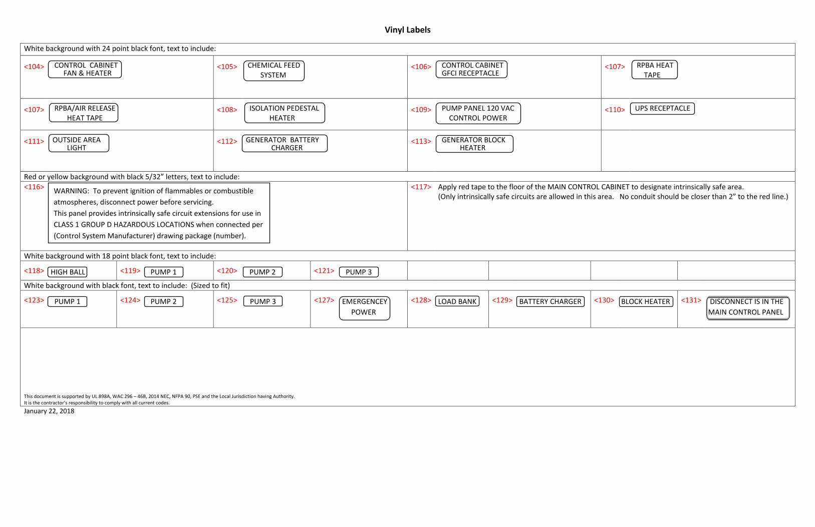
Vinyl Labels White background with 24 point black font, text to include: <104> CONTROL CABINET
FAN & HEATER
<105> CHEMICAL FEED SYSTEM
<106> CONTROL CABINET GFCI RECEPTACLE
<107> RPBA HEAT TAPE
<107> RPBA/AIR RELEASE
HEAT TAPE
<108> ISOLATION PEDESTAL HEATER
<109> PUMP PANEL 120 VAC CONTROL POWER
<110> UPS RECEPTACLE
<111> OUTSIDE AREA
LIGHT
<112> GENERATOR BATTERY CHARGER
<113> GENERATOR BLOCK HEATER
Red or yellow background with black 5/32” letters, text to include: <116> <117> Apply red tape to the floor of the MAIN CONTROL CABINET to designate intrinsically safe area.
(Only intrinsically safe circuits are allowed in this area. No conduit should be closer than 2” to the red line.)
White background with 18 point black font, text to include: <118> HIGH BALL <119> PUMP 1 <120> PUMP 2 <121> PUMP 3
White background with black font, text to include: (Sized to fit) <123> PUMP 1 <124> PUMP 2 <125> PUMP 3 <127> EMERGENCEY
POWER <128> LOAD BANK <129> BATTERY CHARGER <130> BLOCK HEATER <131> DISCONNECT IS IN THE
MAIN CONTROL PANEL
This document is supported by UL 898A, WAC 296 – 46B, 2014 NEC, NFPA 90, PSE and the Local Jurisdiction having Authority. It is the contractor’s responsibility to comply with all current codes. January 22, 2018
WARNING: To prevent ignition of flammables or combustible atmospheres, disconnect power before servicing. This panel provides intrinsically safe circuit extensions for use in CLASS 1 GROUP D HAZARDOUS LOCATIONS when connected per (Control System Manufacturer) drawing package (number).
Ekeyt
Text Box
K - 23
Ekeyt
Text Box
08/2017

Ekeyt
Text Box
K - 24
Ekeyt
Text Box
08/2017

Ekeyt
Text Box
K - 25
Ekeyt
Text Box
08/2017
Ekeyt
Text Box
K - 26
Ekeyt
Text Box
08/2017

Ekeyt
Text Box
K - 27
Ekeyt
Text Box
08/2017

Ekeyt
Text Box
K - 28
Ekeyt
Text Box
08/2017

Ekeyt
Text Box
K - 29
Ekeyt
Text Box
08/2017

Ekeyt
Text Box
K - 30
Ekeyt
Text Box
08/2017

Ekeyt
Text Box
K - 31
Ekeyt
Text Box
08/2017
Ekeyt
Text Box
K - 32
Ekeyt
Text Box
08/2017