Appendix G: Geology and Geotechnical
44
Appendix G: Geology and Geotechnical
Transcript of Appendix G: Geology and Geotechnical
Appendix G: Geology and
Geotechnical


Geology

GEOTECHNICAL INVESTIGATION FOR THE PROPOSED CONTINUOUS ASH DISPOSAL
FACILITY FOR THE MATIMBA POWER STATION LOCATED IN LEPHALALE, LIMPOPO PROVINCE
APRIL 2013
TABLE OF CONTENTS
Contents 1 INTRODUCTION ............................................................................................................................ 1
1.1 Preamble ................................................................................................................................. 1 1.2 Objectives ................................................................................................................................ 1
2 FACTUAL REPORT ....................................................................................................................... 1
2.1 Programme of Work ................................................................................................................ 1 2.1.1 Sources of Information .................................................................................................... 1 2.1.2 Fieldwork ......................................................................................................................... 1
2.2 Site Description ....................................................................................................................... 1 2.3 Climate .................................................................................................................................... 1 2.4 Topography ............................................................................................................................. 1 2.5 Geology ................................................................................................................................... 5
3 GEOTECHNICAL SITE CLASSIFICATIONS ................................................................................. 6
3.1 Pedeology ............................................................................................................................... 6 3.2 Water Table ............................................................................................................................. 6 3.3 Excavatibility of the Ground .................................................................................................... 6 3.4 Mining Activity ......................................................................................................................... 6 3.5 Instability in areas of soluble rock ........................................................................................... 7 3.6 Steep Slope ............................................................................................................................. 7 3.7 Areas subject to seismic activity ............................................................................................. 7 3.8 Additional Investigations ......................................................................................................... 8
4 GEOLOGICAL AND GEOTECHNICAL SENSITIVE AREAS ........................................................ 8
5 CONCLUSION AND RECOMMENDATIONS .............................................................................. 11
List of Figures Figure 1: A field geologist recording coordinates using a hand-held GPS. ............................................ 2 Figure 2: A view of the study area on Google Earth. .............................................................................. 2 Figure 3: A view of the current dumping site........................................................................................... 3 Figure 4: Typical vegetation of the study area. ....................................................................................... 3 Figure 5: Map of the study area demarcated in the red circle. ............................................................... 4 Figure 6: An abstract of site geology from 1:250 000 geological map. ................................................... 5 Figure 7: Mining potential across different zones and rock formations. ................................................. 7 Figure 8: Geological sensitive areas. ...................................................................................................... 9 Figure 9: Geological sensitive areas. .................................................................................................... 10
List of Tables Table 1: Summarized geology of the site. ............................................................................................... 5

1 INTRODUCTION
1.1 Preamble
This report discusses preliminary geological and geotechnical conditions and constraints of the new proposed development as per the South African Institution of Civil Engineering (SAICE)’s “Guidelines for Urban Engineering Geological Investigations”.
1.2 Objectives
The objectives of the investigation were to complete a preliminary geological and geotechnical survey, covering an eight kilometre (km) radius from the Matimba Power Station by:
Reviewing previous studies conducted by other consultants around the area; and
Consulting relevant authorities such as Department of Mineral Resources (DMR), Council for Geoscience (CGS) and Department of Water Affairs (DWA) to obtain any available data.
2 FACTUAL REPORT
2.1 Programme of Work
2.1.1 Sources of Information
A 1:250 000 2326 Ellisras geological map.
2.1.2 Fieldwork
On the 6th August 2012, a field team departed to the proposed development study area and a walk-over
survey was conducted on the initial proposed 5km zone. However, the team only had access to farm Zwartwater 507 LQ owned by Eskom. A walk was taken across the farm and mapping of geological features was conducted and coordinates were recorded using a hand-held Global Positioning System (GPS) with an accuracy of less than 0.5m (Figure 1).
2.2 Site Description
The area under investigation is located in Lephalale, North West of Polokwane in the Limpopo Province. Figure 2 shows an aerial image from Google Earth indicating the location of the study area. The study area contains a pre-existing ash disposal area (Figure 3) and the vegetation comprises of thorn trees and veld grass (Figure 4).
2.3 Climate
The area under investigation lies in the Transvaal Highvelds’ semi-arid warm climatic zone with annual maximum and minimum average temperatures of approximately 32
oC and 4
oC respectively. The
average annual rainfall is approximately 400mm, most of which occurs in heavy isolated falls between November and March. The "Weinert N-Value", that describes the climatic environment, is approximately 4.5 for the area.
2.4 Topography
Topography of Lephalale is generally flat and it is expected that surface water drainage will be in the form of sheetwash towards the water courses (Figure 5).

Figure 1: A field geologist recording coordinates using a hand-held GPS.
Figure 2: A view of the study area on Google Earth.
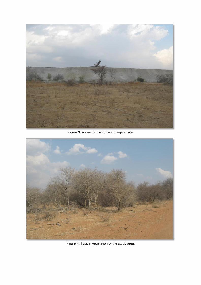
Figure 3: A view of the current dumping site.
Figure 4: Typical vegetation of the study area.

Figure 5: Map of the study area demarcated in the red circle.
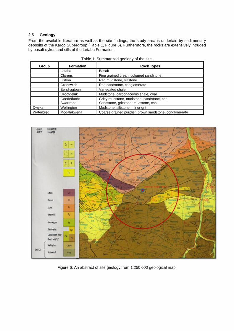
2.5 Geology
From the available literature as well as the site findings, the study area is underlain by sedimentary deposits of the Karoo Supergroup (Table 1, Figure 6). Furthermore, the rocks are extensively intruded by basalt dykes and sills of the Letaba Formation.
Table 1: Summarized geology of the site.
Group Formation Rock Types
Letaba Basalt
Clarens Fine grained cream coloured sandstone
Lisbon Red mudstone, siltstone
Greenwich Red sandstone, conglomerate
Eendragtpan Variegated shale
Grootgeluk Mudstone, carbonaceous shale, coal
Goededacht Swartrant
Gritty mudstone, mudstone, sandstone, coal Sandstone, gritstone, mudstone, coal
Dwyka Wellington Mudstone, siltstone, minor grit
Waterbreg Mogalakwena Coarse grained purplish brown sandstone, conglomerate
Figure 6: An abstract of site geology from 1:250 000 geological map.

3 GEOTECHNICAL SITE CLASSIFICATIONS
3.1 Pedeology
The expected soil cover is less than 1.0m thick comprising of aeolian and residual sands. It is therefore expected that insignificant soil cover will be recovered from this study area and will need to be collected from another source. The presence of insignificant soil cover underlain by moderately to slightly weathered rock indicates that an unconfined compressive strength of between 70 and 130Mpa can be given for the rock types and the development of associated structures can be founded with less chance of settlement.
3.2 Water Table
A search was conducted from Department of Water Affairs’ database to understand the groundwater regime around the investigated area. Unfortunately, the results of the search indicate that no registered borehole data is available within 15km radius and as such the depth to permanent water table is unknown. However, presence of ferricrete as seen on one of the attempted excavation, suggest potential seasonal fluctuation of the water table during rainy seasons.
It should also be indicated that no permeability tests were carried out during this phase of the investigation, however previous studies show that the underlying rock type is less permeable. To determine whether the surface will require lining, can only be determined if the depth to the water table is known and relevant tests have been conducted.
3.3 Excavatibility of the Ground
This geotechnical characteristic will clearly be defined in the second phase of the investigation where trial pitting will take place. However, previous studies and walk-over survey findings indicate that bedrock is expected at surface or at shallow depths.
3.4 Mining Activity
The area falls within the Waterberg Coalfield and Exxaro’s Grootegeluk Coal Mine, one of South Africa largest coal producing mine is situated within the area. The Grootegeluk Mine supplies coal to the Matimba Power Station and it is anticipated that the mine will also be supplying the new Medupi Power Station which currently under construction. To date, the mine is the major role player in the Waterberg and it is anticipated that in the near future, several prospecting and mining rights could be granted in the area.
Other mining activities taking place in the area include mining of fluorspar and quarrying of sandstone south-west of Matimba Power Station. As such, there is a possibility that the proposed development could largely be hindered by mining activities across the area. The map shown in Figure 7 indicates different zones according to the possibility of future mining activity in the area. Different formations have been zoned according to their prospect of future mining across the area. These zones have been classified according to depth to the coal seam and depth increases gradually from Zone A to Zone D. Zone A, on which the Grootegeluk mine is located comprises coal seams nearer to the surface. Though Zone D looks less lucrative due to the expected coal seams depths from surface, the occurrence of fluorspar mining and sandstone quarrying were noted.
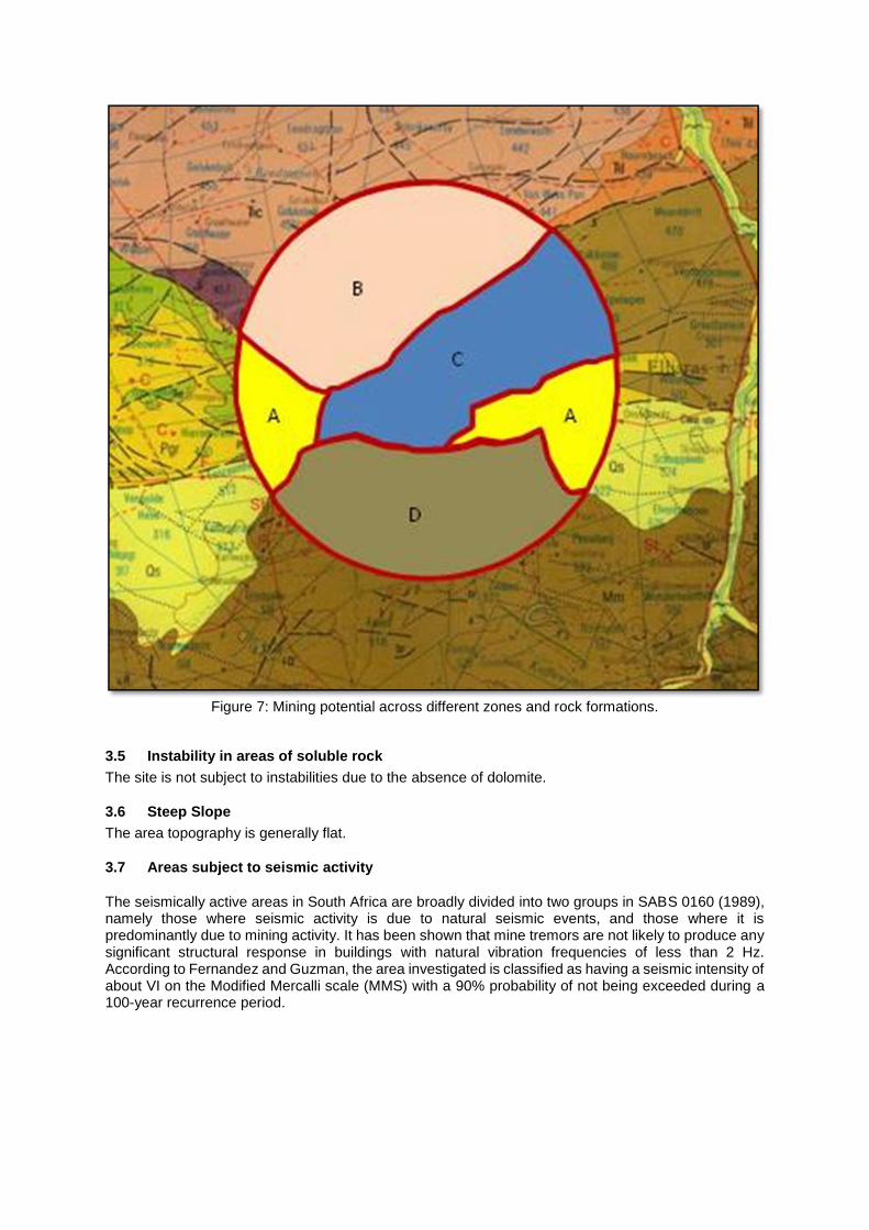
Figure 7: Mining potential across different zones and rock formations.
3.5 Instability in areas of soluble rock
The site is not subject to instabilities due to the absence of dolomite.
3.6 Steep Slope
The area topography is generally flat.
3.7 Areas subject to seismic activity
The seismically active areas in South Africa are broadly divided into two groups in SABS 0160 (1989), namely those where seismic activity is due to natural seismic events, and those where it is predominantly due to mining activity. It has been shown that mine tremors are not likely to produce any significant structural response in buildings with natural vibration frequencies of less than 2 Hz. According to Fernandez and Guzman, the area investigated is classified as having a seismic intensity of about VI on the Modified Mercalli scale (MMS) with a 90% probability of not being exceeded during a 100-year recurrence period.
3.8 Additional Investigations
This report provides a preliminary assessment of the study area conditions and that detailed work will be undertaken on the second phase of the investigation. The second phase of this study will comprise trial pitting, detailed mapping and zoning of the site according to “Geotechnical Classification for Urban Development” (after Partridge, Wood and Brink), where an ArcGIS map will be produced indicating different classes according to the classification mentioned above.
Through trial pitting and laboratory testing, we will be able to determine engineering properties of the underlying soils and rock. This will therefore, enable the provision of acceptable bearing capacity of different horizons for foundation purposes, to classify the soils for use as backfill/ cover of the ash pile and to quantify the available material.
Percolation tests will also be conducted at the base of selected trial pits in order to determine the permeability of the underlying soil rocks. This will assist in evaluating potential groundwater contamination and assessing the aquifers for vulnerability.
An application to access information was submitted to Council of Geoscience to acquire results of any ground or airborne geophysical surveys as this will assist in the delineation of any geological structures on site. However, at the time of preparation of this report, the requested information had not been made available and will hence be included in the second phase report.
The specific objectives of the second phase investigation has been summarised as follows:
Identify the soil/rock profile to a depth of approximately 3.0m or refusal of a TLB;
Determine the engineering properties and parameters of the near surface soils;
Assess the suitability of the near surface soils for use as backfill;
Determine the corrosivity of the soil and water encountered in the trial holes;
Assess the permeability of the near surface soils/ rock by undertaking percolation tests at the bottom of selected trial pits;
Evaluate potential groundwater contamination and classify and assess the aquifers for vulnerability; and
Comment upon any geotechnical constraints that might impact the proposed development.
4 GEOLOGICAL AND GEOTECHNICAL SENSITIVE AREAS
Figure 8 and Figure 9 below indicate the areas within the study area which are sensitive and could potentially hinder the proposed development. It is essential to note that identification of these areas as sensitive was solely based on the findings of this desktop study. However, the selection will be confirmed during the second phase of the survey before any conclusions can be made.

Figure 8: Geological sensitive areas.
Figure 8: Geological sensitive areas.

Figure 9: Geological sensitive areas.

5 CONCLUSION AND RECOMMENDATIONS
Subsequent to the preliminary analysis of the geological and geotechnical characteristics of the study area, it can be concluded that the presence of groundwater bearing geological structures in the northern side of the study area does pose a risk to the proposed development. Moreover, the proposed development could largely be hindered by prospect of mining across the area.
It is therefore recommended that a detailed second phase investigation be undertaken in the EIA phase in order to further identify a suitable site.
1. REFERENCE
Jennings, J.E et al. (1973). "Revised Guide to Soil profiling for Civil Engineering Purposes in
Southern Africa”. Civil Engineer in South Africa.
TRH 14, "Guidelines for Road Construction Materials" - NITRR, 1985
Guidelines for Soil and Rock Logging in South Africa - AEG-SA section, SAICE, SAIEG - 2002.
Minimum Requirements for Waste Disposal by Landfill. Department of Water Affairs and Forestry Republic of South Africa. 2nd edition 1998.
SAICE’s Guidelines for Urban Engineering Geological Investigations.
Fernandez L. M. and Guzman J. A. (1979). Earthquake hazards in Southern Africa. Seismological Series 10, Published by Geological Survey of South Africa.
Geotechnical
DETAILED GEOTECHNICAL INVESTIGATION FOR THE PROPOSED CONTINUOUS ASH DISPOSAL
FACILITY FOR THE MATIMBA POWER STATION IN LEPHALALE, LIMPOPO PROVINCE,
SOUTH AFRICA
DEA REFERENCE NUMBER: 14/12/16/3/3/3/56
Author: S. Pather (Pr.Sci.Nat.)
Date: 09 August 2013
Report Reference Number: SGE-050-2013
Prepared for:
Royal HaskoningDHV P.O. Box 867 Gallo Manor 2052 South Africa Prepared by:
Kai Batla Minerals Industry Consultants 26 Republic Road, Kai Batla House Bordeaux Randburg South Africa
TABLE OF CONTENTS
1. TERMS OF REFERENCE 1
2. SCOPE OF REPORT 1
3. INFORMATION SUPPLIED 1
4. NATURE OF INVESTIGATION 1
4.1 Inspection Pits 2
4.2 CBR Dynamic Probe Light (DPL) Tests 2
4.3 CBR Dynamic Cone Penetrometer (DCP) Tests 2
4.4 Percolation Tests 2
4.5 Laboratory Tests 2
5. DESCRIPTION OF STUDY AREA 3
6. GEOLOGY OF STUDY AREA 4
6.1 Site Alternative 1 4 6.2 Site Alternative 2 5 6.3 Conveyor Belt Route to Site Alternative 2 6
7. GROUNDWATER OCCURRENCE 7
8. LABORATORY TESTS RESULTS 7
9. DISCUSSION 12
9.1 Proposed Development 12 9.2 General Stability of the Sites 12 9.3 Excavatability and Rippability 13 9.4 Materials Classification and Usage 14 9.5 Drainage 15 9.6 Trench Stability 15 9.7 Suitability of Insitu Materials for Use as Trench Backfill 15 9.8 Development of Building Platforms 16 9.9 Subgrade Treatment for Roads, Surface Beds and Parking Areas 17 9.10 Foundations for Building Structures 17 9.11 Foundations for Conveyor Belt to Site Alternative 2 18 9.12 Soil Resistivity and Cathodic Protection 19 9.13 Percolation Rates of Subsoil Materials 20 10. STABILITY OF ASH DISPOSAL FACILITY
21
11. SUITABILITY OF SITES FOR ASH DISPOSAL FACILITY 22 12. DEFORMATION/MOVEMENT MONITORING OF ASH FACILITY/PILES 22
13. CONCLUSIONS 23 14. REFERENCES 24
1 | P a g e
1. TERMS OF REFERENCE
Royal HaskoningDHV (Pty) Ltd (RHDHV) was appointed by Eskom Holdings SoC Limited (“Eskom”) to
conduct an Environmental Impact Assessment (EIA) study for the proposed construction of a
continuous ash disposal facility for the Matimba Power Station in Lephalale, Limpopo province, South
Africa.
Kai Batla Holdings (KBH) was subsequently appointed by RHDHV to provide an assessment of the
potential impacts on geology associated with the proposed construction of the ash disposal facility.
2. SCOPE OF REPORT
This report sets out the results of a Detailed Geotechnical Investigation carried out for the proposed
“Continuous Ash Disposal Facility for the Matimba Power Station in Lephalale, Limpopo Province,
South Africa”, which forms part of a specialist study required for the EIA. The geological and
geotechnical aspects of the study areas (Site Alternatives 1 and 2 and Linear infrastructure route to
Site Alternative 2) are discussed, and recommendations are provided for the avoidance or mitigation
of negative impacts, where possible.
Recommendations for stability, earthworks, drainage, materials excavatability/rippability, foundations,
materials usage and subgrade treatment for roads and parking areas are also provided. Finally,
comparisons of both site alternatives are made and reasons provided for development of the preferred
site.
3. INFORMATION SUPPLIED
For the purposes of assisting with this investigation, RHDHV provided the following information to
KBH:
Global Positioning System (GPS) co-ordinates and boundaries of the study areas;
Proposed alignment of Linear infrastructure Route to Site Alternative 2; and
Contact details of the relevant Eskom officials for Site 1 and landowners for Site 2.
KBH also made reference to a report titled “Desktop Report for New Proposed Ash Dump in Matimba
Power Station in Lephalale, Limpopo Province” (Mahlangu, T., 2013).
4. NATURE OF INVESTIGATION
The fieldwork for the investigation was conducted in June 2013 and comprised the following:
Inspection Pits;
California Bearing Ratio (CBR) Dynamic Probe Light (DPL) tests;
California Bearing Ratio (CBR) Dynamic Cone Penetrometer (DCP) tests;

2 | P a g e
Percolation tests; and
Soil/Bedrock sampling.
4.1 Inspection Pits
Sixty six inspection pits (IP), designated IP1 through IP27 for Site Alternative 1, IP1 through IP29 for
Site Alternative 2 and IP1 through 10 for the Conveyor Belt Route, were excavated using a Tractor
Loader Backhoe (TLB) and hand auger at the approximate positions indicated in Figures 1 - 3. The
inspection pits were extended to depths in the range of 1.0 to 4.5 metres below existing ground level
and were profiled using the “Guidelines for Soil and Rock Logging in South Africa”, (Brink, A.B.A. and
Bruin, R.M.H., 2001). Copies of the detailed profiles are given in Appendix A.
4.2 CBR Dynamic Probe Light (DPL) Tests
Fifty six CBR Dynamic Probe Light (DPL) tests, designated DPL1 through DPL27 for Site Alternative 1
and DPL1 through DPL29 for Site Alternative 2, were carried out at the approximate positions given in
Figures 1 and 2. The DPL tests were advanced to depths of equipment refusal. The results of the
DPL tests comprising plots of blow counts versus depth are given in Appendix B.
4.3 CBR Dynamic Cone Penetrometer (DCP) Tests
Fourteen CBR Dynamic Cone Penetrometer (DCP) tests, designated DCP1 through DCP14 for the
linear infrastructure route, were carried out at the approximate positions given in Figure 3. The DCP
tests were advanced to depths of equipment refusal or to a final depth of 4.0 metres below existing
ground level. The results of the DCP tests comprising plots of blow counts versus depth are given in
Appendix C.
4.4 Percolation Tests
Eight percolation tests were conducted on site to determine the permeability of the subsoils. Each test
comprised the excavation of a hole to a depth of 0.3 metres into the subsoil/bedrock materials being
tested, pre-soaking of the hole and thereafter recording the average fall in the level of water over a
period of 35 minutes. The results of the percolation tests are summarised and discussed in Section 9.
4.5 Laboratory Tests
Disturbed samples were retrieved from the inspection pits and sent to a soil materials laboratory for
the following laboratory tests:
3 | P a g e
Particle size distribution/grading;
Atterberg Limits;
Modified AASHTO;
California Bearing Ratio (CBR);
Hydrometer Analyses;
Performance as Wearing Course; and
Soil Box Resistivity.
The results of the laboratory tests are summarised in Section 8 and given in Appendix C.
5. DESCRIPTION OF STUDY AREA
The study area is located in Lephalale, Limpopo Province; two site alternatives were selected for
detailed assessment during the EIA phase. The sites are located at approximate GPS co-ordinates
S23o43’02.42” and E27
o36’10.50” (Site Alternative 1) and S23
o36’44.73” and E27
o36’18.75” (Site
Alternative 2). The proposed new ash disposal facility for Site 1 is to be extended to the western and
southwestern ends of an existing facility (on farm Zwartwater 507LQ), and for Site 2, north of the
Matimba Power Station. Site 2 spans across 4 game farms, namely, Appelvlakte 448LQ, Vooruit
449LQ, Drooghuewel 447LQ and Ganzepan 446LQ.
From the available contour maps, drainage is affected in an easterly direction, the approximate fall in
ground level being 20 metres over 5km from west to east. Vegetation consists essentially of thick
indigenous bush and trees up to approximately 12 metres in height. Grass cover is sparse and
access for conventional vehicles is difficult due to heavy undergrowth and loose sandy surface.
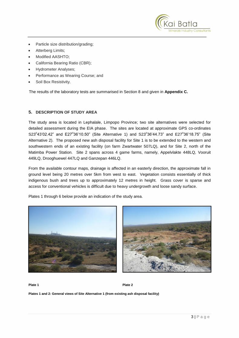
Plates 1 through 6 below provide an indication of the study area.
Plate 1 Plate 2
Plates 1 and 2: General views of Site Alternative 1 (from existing ash disposal facility)

4 | P a g e
Plate 3 Plate 4
Plates 3 and 4: General views of Site Alternative 2 (existing farms north of Matimba Power Station)
Plate 5 Plate 6
Plates 5 and 6: General views of Conveyor Belt Route
6. GEOLOGY OF STUDY AREA
6.1 Site Alternative 1
The general geology of the site is characterised by Aeolian (wind-blown) sands of the Karoo
Supergroup, which overlie conglomerate and sandstone bedrock of the Waterberg Group, Sandriviers
Formation (Anhaeusser et al., 2006).

5 | P a g e
The Aeolian sands are described as dry to very slightly moist, yellowish/orange brown to reddish
brown, medium dense to dense becoming very dense with depth, fine grained, silty sand. This layer
extends to top of bedrock, at depths in the range 1.0 – 2.0 metres below existing ground level.
The conglomerate bedrock occurs as outcrops in some areas and is mainly present across the central
and southern portions of the site. The conglomerate is described as greyish/yellowish/orange brown
to purplish grey, moderately to highly weathered, fine to coarse grained (with numerous subrounded to
subangular pebbles), moderately to highly fractured, medium hard rock.
The sandstone bedrock underlies the conglomerate and is described as greyish/orange brown to
pinkish brown, highly to moderately weathered, moderately bedded, highly fractured/jointed, soft rock
(becoming progressively slightly weathered and medium hard to hard with depth).
In some instances conglomerate is absent and the Aeolian sandy soils are underlain directly by
sandstone bedrock.
Plates 7 and 8 below provide an indication of the typical subsoil materials encountered across the site.
Plate 7: Typical Aeolian sandy soils Plate 8: Pebbly conglomerate bedrock outcrop
6.2 Site Alternative 2
The general geology of the site is characterised by colluvial sandy soils and Aeolian (wind-blown)
sands of the Karoo Supergroup, which overlie pedogenic soils (calcrete) and sandstone bedrock of the
Ellisras Basin, Clarens Formation (Anhaeusser et al., 2006).
The colluvial topsoil is described as moderate brown, loose to medium dense, slightly clayey, fine
grained, silty sand. The colluvial soils extend to an average depth of 0.3 metres below existing ground
level.
The Aeolian sands are described as dry to very slightly moist, orange/reddish brown, medium dense
becoming dense with depth, fine grained, silty sand. This layer extends to top of calcrete at variable
depths, generally in the range 1.5 to 3.5 metres below existing ground level.

6 | P a g e
The nodular calcrete layer is described as whitish grey to creamish white, moderately to highly
weathered, fine to medium grained, moderately to highly fractured, soft to medium hard rock.
Grey, alluvial sandy soils were encountered in IP2 and IP19 along the northern boundary of the site.
Sandstone bedrock was not encountered across the site but is anticipated at depths in the range 5.0
to 10.0 metres below existing ground level.
Plates 9 and 10 below provide an indication of the typical subsoil materials encountered across the
site.
Plate 9: Aeolian sandy soils underlain by calcrete Plate 10: Colluvial soils and nodular calcrete (spoil)
6.3 Linear infrastructure Route to Site Alternative 2
The general geology along the route is characterised by colluvial sandy soils and Aeolian (wind-blown)
sands of the Karoo Supergroup, which overlie pedogenic soils (calcrete) and sandstone/conglomerate
bedrock of the Ellisras Basin, Clarens Formation (Anhaeusser et al., 2006).
The colluvial topsoil is described as greyish brown, very loose to loose, fine grained, silty sand. The
colluvial soils extend to an average depth of 0.3 metres below existing ground level.
The Aeolian sands are described as slightly moist to moist, orange brown, loose to medium dense,
fine grained, slightly silty sand. This layer extends to top of calcrete or sandstone/conglomerate
bedrock at variable depths, generally in the range 1.8 to 3.5 metres below existing ground level.
The nodular calcrete layer is described as whitish grey to creamish white, moderately to highly
weathered, fine to medium grained, moderately to highly fractured, soft to medium hard rock.
Sandstone/conglomerate bedrock is anticipated to occur at variable depths in the range 1.8 to 5.0
metres below existing ground level.
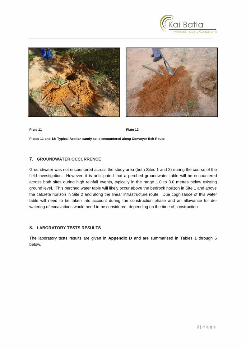
Plates 11 and 12 below provide an indication of the typical subsoil materials encountered across the
site.
7 | P a g e
Plate 11 Plate 12
Plates 11 and 12: Typical Aeolian sandy soils encountered along Conveyor Belt Route
7. GROUNDWATER OCCURRENCE
Groundwater was not encountered across the study area (both Sites 1 and 2) during the course of the
field investigation. However, it is anticipated that a perched groundwater table will be encountered
across both sites during high rainfall events, typically in the range 1.0 to 3.0 metres below existing
ground level. This perched water table will likely occur above the bedrock horizon in Site 1 and above
the calcrete horizon in Site 2 and along the linear infrastructure route. Due cognisance of this water
table will need to be taken into account during the construction phase and an allowance for de-
watering of excavations would need to be considered, depending on the time of construction.
8. LABORATORY TESTS RESULTS
The laboratory tests results are given in Appendix D and are summarised in Tables 1 through 6
below.
8 | P a g e
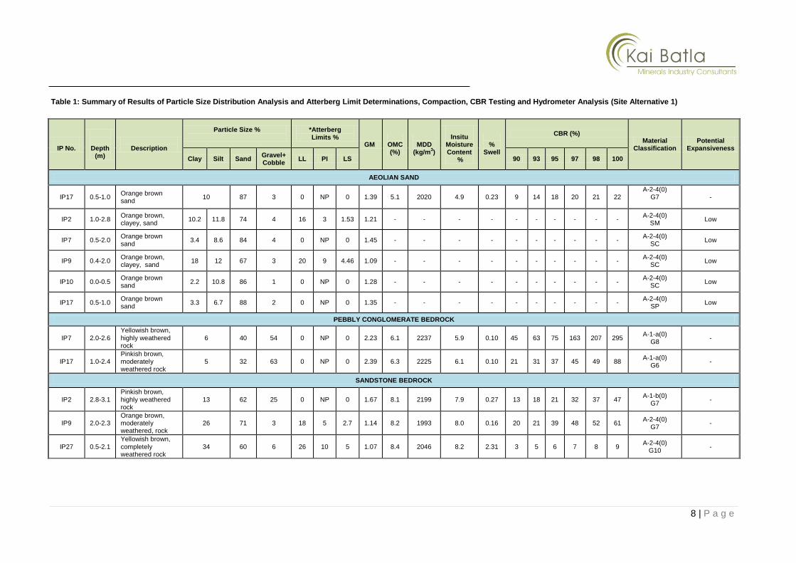
Table 1: Summary of Results of Particle Size Distribution Analysis and Atterberg Limit Determinations, Compaction, CBR Testing and Hydrometer Analysis (Site Alternative 1)
IP No.
Depth (m)
Description
Particle Size %
*Atterberg Limits %
GM
OMC (%)
MDD
(kg/m3)
Insitu
Moisture Content
%
%
Swell
CBR (%) Material
Classification Potential
Expansiveness
Clay Silt Sand Gravel+ Cobble
LL PI LS 90 93 95 97 98 100
AEOLIAN SAND
IP17 0.5-1.0 Orange brown sand
10 87 3 0 NP 0 1.39 5.1 2020 4.9 0.23 9 14 18 20 21 22 A-2-4(0)
G7
-
IP2 1.0-2.8 Orange brown, clayey, sand
10.2 11.8 74 4 16 3 1.53 1.21 - - - - - - - - - - A-2-4(0)
SM Low
IP7 0.5-2.0 Orange brown sand
3.4 8.6 84 4 0 NP 0 1.45 - - - - - - - - - - A-2-4(0)
SC Low
IP9 0.4-2.0 Orange brown, clayey, sand
18 12 67 3 20 9 4.46 1.09 - - - - - - - - - - A-2-4(0)
SC Low
IP10 0.0-0.5 Orange brown sand
2.2 10.8 86 1 0 NP 0 1.28 - - - - - - - - - - A-2-4(0)
SC Low
IP17 0.5-1.0 Orange brown sand
3.3 6.7 88 2 0 NP 0 1.35 - - - - - - - - - - A-2-4(0)
SP Low
PEBBLY CONGLOMERATE BEDROCK
IP7 2.0-2.6 Yellowish brown, highly weathered rock
6 40 54 0 NP 0 2.23 6.1 2237 5.9 0.10 45 63 75 163 207 295 A-1-a(0)
G8 -
IP17 1.0-2.4 Pinkish brown, moderately weathered rock
5 32 63 0 NP 0 2.39 6.3 2225 6.1 0.10 21 31 37 45 49 88 A-1-a(0)
G6 -
SANDSTONE BEDROCK
IP2 2.8-3.1 Pinkish brown, highly weathered rock
13 62 25 0 NP 0 1.67 8.1 2199 7.9 0.27 13 18 21 32 37 47 A-1-b(0)
G7 -
IP9 2.0-2.3 Orange brown, moderately weathered, rock
26 71 3 18 5 2.7 1.14 8.2 1993 8.0 0.16 20 21 39 48 52 61 A-2-4(0)
G7 -
IP27 0.5-2.1
Yellowish brown,
completely weathered rock
34 60 6 26 10 5 1.07 8.4 2046 8.2 2.31 3 5 6 7 8 9 A-2-4(0)
G10 -

9 | P a g e
LL - Liquid Limit OMC - Optimum Moisture Content A-3 (0) - Revised U.S Classification PI - Plasticity Index LS - Linear Shrinkage GM - Grading Modulus NP - Non Plastic CBD - Could Not Be Determined Low - Potential Expansiveness MDD - Maximum dry density G7 – TRH14 Classification SM – Unified Soil Classification CBR – California Bearing Ratio
Table 2: Summary of Results of Wearing Course (Site Alternative 1)
IP No. Depth (m) Description Performance as Wearing Course
IP2 1.0-2.8 Orange brown, clayey, sand (Aeolian) Ravels and Corrugates
IP7 0.5-2.0 Orange brown sand (Aeolian) Ravels and Corrugates
IP9 0.4-2.0 Orange brown, clayey, sand (Aeolian) Erodible Materials
IP10 0.0-0.5 Orange brown sand (Aeolian) Ravels and Corrugates
IP17 0.5-1.0 Orange brown sand (Aeolian) Ravels and Corrugates
Table 3: Summary of Results of Soil Box Resistivity Tests (Site Alternative 1)
IP No. Depth (m) Description Resistivity, Ohm.m
(Mega Earth Tester)
IP2 1.0-2.8 Orange brown, clayey, sand (Aeolian) >499
IP7 0.5-2.0 Orange brown sand (Aeolian) 454
IP9 0.4-2.0 Orange brown, clayey, sand (Aeolian) 171
IP10 0.0-0.5 Orange brown sand (Aeolian) >499
IP17 0.5-1.0 Orange brown sand (Aeolian) >499
10 | P a g e
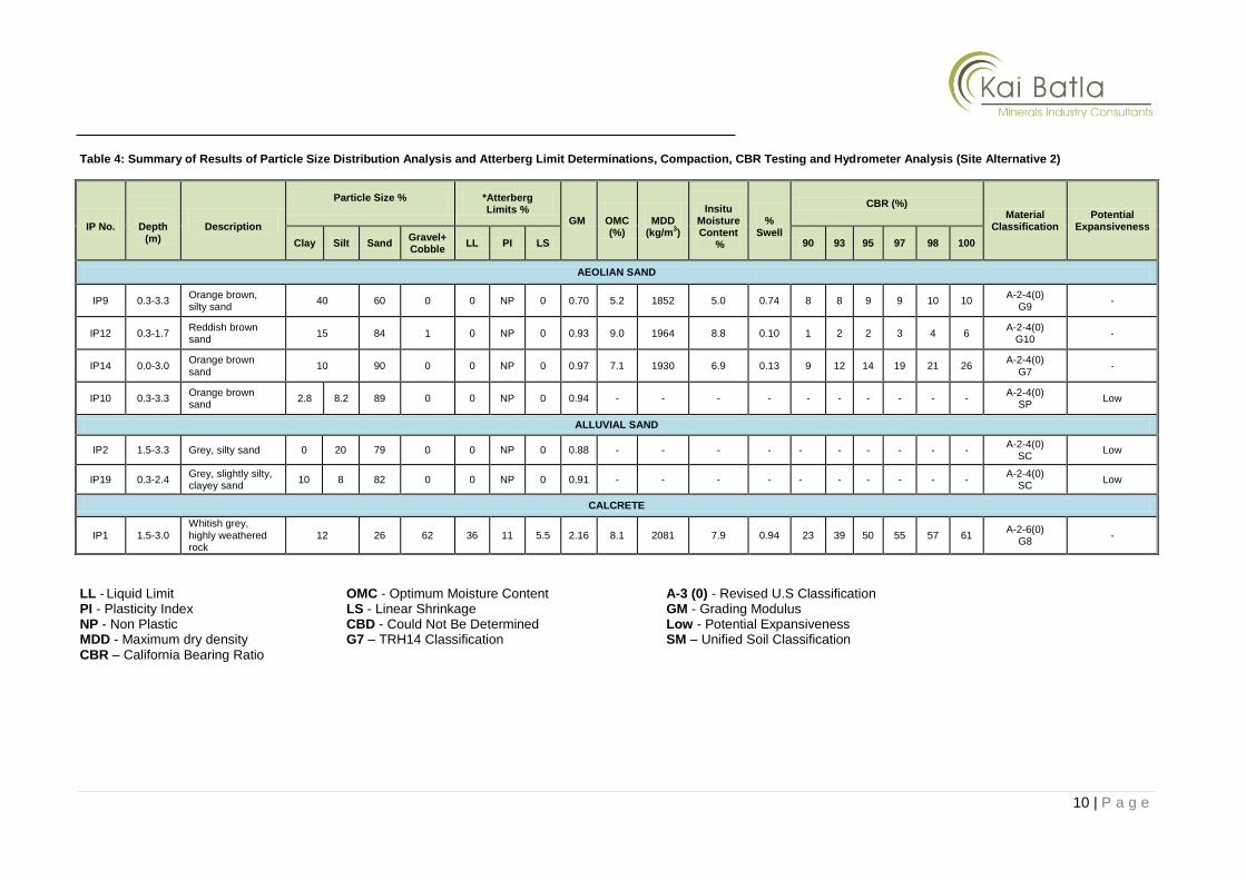
Table 4: Summary of Results of Particle Size Distribution Analysis and Atterberg Limit Determinations, Compaction, CBR Testing and Hydrometer Analysis (Site Alternative 2)
LL - Liquid Limit OMC - Optimum Moisture Content A-3 (0) - Revised U.S Classification PI - Plasticity Index LS - Linear Shrinkage GM - Grading Modulus NP - Non Plastic CBD - Could Not Be Determined Low - Potential Expansiveness MDD - Maximum dry density G7 – TRH14 Classification SM – Unified Soil Classification CBR – California Bearing Ratio
IP No.
Depth (m)
Description
Particle Size %
*Atterberg Limits %
GM
OMC (%)
MDD
(kg/m3)
Insitu
Moisture Content
%
%
Swell
CBR (%) Material
Classification Potential
Expansiveness
Clay Silt Sand Gravel+ Cobble
LL PI LS 90 93 95 97 98 100
AEOLIAN SAND
IP9 0.3-3.3 Orange brown, silty sand
40 60 0 0 NP 0 0.70 5.2 1852 5.0 0.74 8 8 9 9 10 10 A-2-4(0)
G9 -
IP12 0.3-1.7 Reddish brown sand
15 84 1 0 NP 0 0.93 9.0 1964 8.8 0.10 1 2 2 3 4 6 A-2-4(0)
G10 -
IP14 0.0-3.0 Orange brown sand
10 90 0 0 NP 0 0.97 7.1 1930 6.9 0.13 9 12 14 19 21 26 A-2-4(0)
G7 -
IP10 0.3-3.3 Orange brown sand
2.8 8.2 89 0 0 NP 0 0.94 - - - - - - - - - - A-2-4(0)
SP Low
ALLUVIAL SAND
IP2 1.5-3.3 Grey, silty sand 0 20 79 0 0 NP 0 0.88 - - - - - - - - - - A-2-4(0)
SC Low
IP19 0.3-2.4 Grey, slightly silty, clayey sand
10 8 82 0 0 NP 0 0.91 - - - - - - - - - - A-2-4(0)
SC Low
CALCRETE
IP1 1.5-3.0 Whitish grey, highly weathered rock
12 26 62 36 11 5.5 2.16 8.1 2081 7.9 0.94 23 39 50 55 57 61 A-2-6(0)
G8 -

11 | P a g e
Table 5: Summary of Results of Wearing Course (Site Alternative 2)
IP No. Depth (m) Description Performance as Wearing Course
IP10 0.3-3.3 Orange brown sand (Aeolian) Ravels and Corrugates
IP2 1.5-3.3 Grey, silty sand (Alluvial) Ravels and Corrugates
IP19 0.3-2.4 Grey, slightly silty, clayey sand (Alluvial) Ravels and Corrugates
Table 6: Summary of Results of Soil Box Resistivity Tests (Site Alternative 2)
IP No. Depth (m) Description Resistivity, Ohm.m
(Mega Earth Tester)
IP2 1.5-3.3 Grey, silty sand (Alluvial) 34
IP19 0.3-2.4 Grey, slightly silty, clayey sand (Alluvial) 28
IP10 0.3-3.3 Orange brown sand (Aeolian) >499
IP27 0.3-4.0 Orange brown sand (Aeolian) 381

12 | P a g e
9. DISCUSSION
9.1 Proposed Development
The proposed development entails the establishment of an ash disposal facility for the
Matimba Power Station to ensure that the power station is able to accommodate the ashing
requirements for its remaining life (approximately 44 years). For the EIA process, two site
alternatives are under investigation (this Geotechnical Study is one of the specialist
investigations currently underway) to determine which site will be suitable for the proposed
development.
It is anticipated that small ancillary building structures (1 to 2 storeys in extent), water
pipelines and roads will be associated with the development. In addition, a new conveyor belt
is proposed to run from the power station to Site Alternative 2 (refer to Figure 3) if this site is
chosen as the preferred Ash Disposal Facility.
An ash disposal facility will need to have the following typical infrastructure constructed:
Conveyor system for ash transportation;
Drainage system;
Site office;
Workshop;
Contractors yard;
Water supply pipelines, for ash/dust suppression;
Ash water return dams;
Storm water control dams – these will be constructed as per the GN 704 of the National
Water Act (No. 36 of 1998);
Storm water control channels;
Access roads to, on and around the facility – these roads include temporary roads during
construction and permanent roads during the operation; and
Ash disposal site – the design of this site will be dependent on aspects such as the
results of the ash classification study, topography etc.
Detailed information of the above infrastructure have not been determined at this stage
because it is dependent on the site that is finally chosen for the establishment of the ash
disposal facility.
9.2 General Stability of the Sites
It is considered that the both sites and Conveyor Belt Route are stable and suitable for
development provided that the recommendations given in this report are adhered to.
No signs of inherent ground instability such as slip scars, tension cracks or sloughing of the
mantle of transported/Aeolian soils were evident during the fieldwork. It is, however,
important to consider the following prior to earthworks and construction of buildings:

13 | P a g e
The Aeolian soils occurring on the site are considered susceptible to erosion by
stormwater and it is important that adequate surface drainage be catered for. Where
necessary, subsoil drains must also be provided particularly if fills are constructed over
water logged/marshy areas and drainage courses. The need for subsoil drains will
depend on design details of the proposed development outlined in Section 9.1 and will
have to be assessed on site during the construction phase.
Earth flows triggered by saturation of the Aeolian sands can cause liquefaction of these
sands, resulting in downslope earthflows.
The stability of the sites will be altered by earthworks operations. It is important therefore
to ensure that the design of the development promotes stable development.
Where the sandstone bedrock joints/bedding planes combine unfavourably with proposed
cut faces on slopes, slope failures could result, particularly where clay gouge and water
seepage is present along joints. The combination of clay gouge filled joints and high
hydrostatic forces induced by rainwater could give rise to slope stability problems. It
should be noted that while no problematic areas were identified in the inspection pits put
down during the fieldwork phase, it is possible that localised, potentially unstable areas
can become exposed during development, i.e. during earthworks.
It is important to allow for onsite inspections and evaluations by an experienced
engineering geologist/geotechnical engineer so that stability problems can be timeously
identified and remedied.
9.3 Excavatability and Rippability
Taking into consideration the inspection pits conducted across the sites by Tractor Loader
Backhoe (TLB) during the geotechnical field investigation, it is anticipated that the rippability
and excavatibility assessment (indicated in Table 7 below) would likely apply to the both site
alternatives.
14 | P a g e
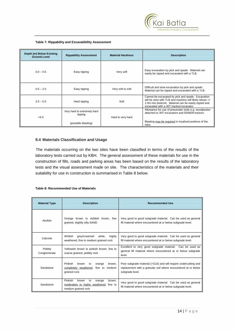
Table 7: Rippability and Excavatibility Assessment
Depth (m) Below Existing Ground Level
Rippability Assessment Material Hardness Description
0.0 – 0.5 Easy ripping Very soft Easy excavation by pick and spade. Material can easily be ripped and excavated with a TLB.
0.5 – 2.0 Easy ripping Very soft to soft Difficult and slow excavation by pick and spade. Material can be ripped and excavated with a TLB.
2.0 – 5.0 Hard ripping Soft
Cannot be excavated by pick and spade. Excavation will be slow with TLB and machine will likely refuse +/- 1.0m into bedrock. Material can be easily ripped and excavated with a 30T tracked excavator.
>5.0
Very hard to extremely hard ripping
(possible blasting)
Hard to very hard
Allowance for use of pneumatic tools e.g. woodpecker attached to 30T excavators and DD9/D9 tractors.
Blasting may be required in localized portions of the sites.
9.4 Materials Classification and Usage
The materials occurring on the two sites have been classified in terms of the results of the
laboratory tests carried out by KBH. The general assessment of these materials for use in the
construction of fills, roads and parking areas has been based on the results of the laboratory
tests and the visual assessment made on site. The characteristics of the materials and their
suitability for use in construction is summarised in Table 8 below.
Table 8: Recommended Use of Materials
Material Type Description Recommended Use
Aeolian Orange brown to reddish brown, fine
grained, slightly silty SAND
Very good to good subgrade material. Can be used as general
fill material where encountered at or below subgrade level.
Calcrete Whitish grey/creamish white, highly
weathered, fine to medium grained rock
Very good to good subgrade material. Can be used as general
fill material where encountered at or below subgrade level.
Pebbly
Conglomerate
Yellowish brown to pinkish brown, fine to
coarse grained, pebbly rock
Excellent to very good subgrade material. Can be used as
general fill material where encountered at or below subgrade
level.
Sandstone
Pinkish brown to orange brown,
completely weathered, fine to medium
grained rock
Poor subgrade material (>G10) and will require undercutting and
replacement with a granular soil where encountered at or below
subgrade level.
Sandstone
Pinkish brown to orange brown,
moderately to highly weathered, fine to
medium grained rock
Very good to good subgrade material. Can be used as general
fill material where encountered at or below subgrade level.

15 | P a g e
9.5 Drainage
The most important factor in the stable development of the sites is the control and removal of
both surface and groundwater from the sites.
Earthworks and drainage measures should be designed in such a way as to prevent ponding
of, or high concentrations of, stormwater or groundwater anywhere on the sites, both during
and after the development.
The terrace should be shaped to a gradient to prevent water ponding on the surface and
should be graded to direct water away from the fill edges and foundations.
9.6 Trench Stability
The sandy Aeolian soils across the study area are anticipated to exhibit moderate to high
collapsible properties. As such, it is considered that trenches excavated in sandy material will
require lateral support, as will trenches excavated in areas with strong groundwater seepage.
Trenches deeper than 1.5m below existing ground level should be shored in any event,
particularly if left open for significant periods.
As a guide, batter slopes for excavation sidewalls should be restricted to the following:
Aeolian sandy soils – 1:2 (vertical: horizontal)
Completely to highly weathered bedrock and calcrete – 1: 0.75
Slightly to moderately weathered bedrock with low discontinuity apertures – vertical
It is recommended that lateral support be used in all situations where shallow groundwater is
encountered and that regular inspections of the trenches are carried out by KBH in order to
detect potentially unstable sidewall conditions during the construction phase.
9.7 Suitability of In situ Materials for Use as Trench Backfill
Based on past experience with the subsoil and surface materials, the suitability of the in situ
materials for use as pipe bedding sand and select/general backfill (Class B/C bedding refers)
is evaluated in accordance with the definitions as set out in SANS 1200LB.
Sources of suitable free-draining coarse granular material for use as “Selected Granular
Material/Bedding Sand” with a Compactability Factor of less than 0.4 will not be
encountered across the sites. It is recommended that allowance therefore be made to import
suitable bedding material for this purpose.
For use as “Select/Main Backfill”, SANS defines materials as subject to not containing
inclusions larger than a fine gravel and a plasticity index (PI) not exceeding six (6). Based on
past experience and testing with similar materials, the in situ materials on both sites comply
with the above definition.
16 | P a g e
Use of the in situ sandy soils, calcrete and weathered bedrock as “General Fill” (present
across the entire study area, consisting of Site Alternatives 1 and 2 is considered feasible
provided the materials are placed in a relatively dry state devoid of organic-rich colluvium,
coarse gravel and boulder inclusions and compacted to 93% Modified AASHTO Maximum
Dry Density at Optimum Moisture Content (OMC).
From experience, the selected granular material requirements in terms of SANS 1200LB are
very seldom met by natural soils. The very strict grading requirements generally only coincide
with artificially blended sands and gravels. Furthermore, the natural variability in composition
within in situ materials will make the establishment of a consistent quality material very
difficult. This could be problematic where the bedding is relied upon for foundation support
and to allay this, additional hoop strength may be required in the design of any proposed
pipelines.
9.8 Development of Building Platforms
All earthworks should be carried out in a manner to promote stable development of both site
alternatives. It is recommended that earthworks be carried out along the guidelines given in
SANS 1200 (current version).
Where natural ground slopes are steeper than 1 vertical to 6 horizontal, the fill must be
benched into the slope. Benches should be 0.5m deep and 2.0m wide.
Fills for the proposed platforms may be constructed using the materials available. Placement
of fill layers should be undertaken in layers not exceeding 200mm thick when placed loose
and compacted using suitable compaction plant to achieve 93% Modified AASHTO maximum
dry density. Density control of placed fill material should be undertaken at regular intervals
during fill construction.
Terraces should be graded to direct water away from the fill edges, and small earth bunds
should be constructed along the crest of the fill, to prevent overtopping and erosion of fill
embankment slopes. These bunds should be a minimum 450mm wide and 300mm high.
Boulders larger than 200mm diameter or 1/3 of the layer thickness when loose should be
removed from the fill material as these could complicate the compaction works, and also
cause piping within fills. Furthermore, large boulders in fills could cause later problems during
construction of foundations.
Cut slopes in soils should be formed to batters of 1 vertical to 1.75 horizontal and to a height
not greater than 1.5m where retaining walls are not provided. Engineered fill slopes should
be formed to batters of 1 vertical to 1.5 horizontal provided that the edge of the fill is over
constructed and thereafter trimmed back to the required position.
Cuts in weathered bedrock should not exceed gradients of 1 vertical in 1 horizontal.
While these recommendations can be applied generally to both site alternatives, experience
has shown that localised variations in stability can occur. Inspection of cuts in weathered
17 | P a g e
bedrock by a competent engineering geologist or geotechnical engineer may indicate that the
angle of cut batter slopes need to be varied locally to promote stability of the site. Cut and fill
heights greater than 1.5m would need to be inspected and approved by an engineering
geologist or geotechnical engineer.
9.9 Subgrade Treatment for Roads, Surface Beds and Parking Areas
The Aeolian sandy soils generally classify as G7 to G9 in terms of TRH14 Classifications.
Where this material is encountered at road subgrade level, it is recommended that the
subsoils be ripped to the specified depth and re-compacted to 93% Modified AASHTO
maximum dry density. Provided the above recommendations are followed, a design CBR of
12 can be adopted.
The completely to highly weathered sandstone bedrock generally classifies as G10 or poorer
in terms of TRH14. Accordingly, where poor road subgrade or surface bed material, as
described above, is exposed, undercutting into the unsuitable materials (depending on the
road formation level or surface bed level) to the specified depth to accommodate a select
layer comprising material of at least G8 quality and compacted to at least 93% Modified
AASHTO dry density is recommended. Provided the above recommendations are followed, a
design CBR of 12 can be adopted.
Where calcrete, pebbly conglomerate and moderately to highly weathered sandstone bedrock
is encountered at road subgrade level (G6 to G8 material), it is recommended that this
material be ripped to the specified depth and re-compacted to 93% Modified AASHTO
maximum dry density. Care should be taken to ensure that the ripped bedrock material is
suitably broken down to eliminate fragments greater than 2/3 of the layer thickness. Provided
the above recommendations are followed, a design CBR of 20 can be adopted.
The pavement formation layer for the proposed roads and parking areas should be designed
taking into account anticipated traffic loads, volumes and design life of the parking area and
road.
9.10 Foundations for Building Structures
It is considered that reinforced strip footings and/or concrete pad bases will be suitable for
single to double storey building structures.
It is recommended that all foundations for the proposed structures be placed onto the
medium dense to dense sandy Aeolian soils where a maximum nett allowable bearing
pressure of 150kN/m2 is considered applicable.
Prior to casting of concrete, the foundation base should be thoroughly compacted with a
heavy rammer or similar to limit settlement. Total settlement is likely to be 5-10mm with
differential settlement taken as 50% of the total settlements.
18 | P a g e
A provision for possible movements between floors and walls should be allowed for in the
design e.g. provision of construction joints and use of appropriate softboard between walls
and floors as per Structural Engineer’s detail.
All brickwork and foundation footings will need to be reinforced as determined by a Structural
Engineer.
Higher bearing pressures of up to 500kN/m2 can also be considered for foundations on
moderately weathered, medium hard to hard rock. For foundations on bedrock, total
settlement is likely to be less than 5mm with differential settlement taken as 50% of the total
settlements.
Where the founding depth to bedrock is greater than about 2.5 metres the use of strip/pad
footings is generally considered impractical and uneconomical, and consideration will need to
be given to adopting a piled foundation solution in order to found in bedrock.
It is considered that the pressure grouted Continuous Flight Auger (CFA) piles are suitable for
use on both site alternatives. Piles must be designed to transfer axial loads into the
weathered bedrock and should be socketed into the bedrock.
A detailed pile design must be carried out taking into account actual pile loads. The pile
installation must also be supervised to ensure that the piles are adequately founded.
9.11 Foundations for Conveyor Belt to Site Alternative 2
The Aeolian sands encountered along the Conveyor Belt Route are considered to be
generally loose in consistency, up to a depth of 3.0 metres below existing ground level. As
such, it is recommended that ground improvement be carried out if shallow foundations are
proposed for the Conveyor Belt.
We recommend that the following be carried out:
Excavate subsoils to a depth and width of at least 1.5 times the least width of the
foundation e.g. the excavation for a 1.2m x 1.2m size spread footing would require to be
1.8m length x 1.8m breadth and 1.8m deep.
Backfill the excavation over the plan area of the excavation to the proposed foundation
level using sandy soils excavated on site. The thickness of the compacted material
should be at least 1200mm and a suitable depth for founding is considered to be 600mm
below final ground level.
The material should be compacted to at least 95% Modified AASHTO dry density at -1%
to +2% of Optimum Moisture Content (OMC). Material will need to be compacted in
stages, in 200mm loose layers.
19 | P a g e
Consideration can be given to stabilising the material with cement. This is advisable as it
would reduce the permeability of the placed material and thus aid in preventing the soils
wetting up and thereby reducing the risk of collapse type settlement.
The proposed structure can be founded on this engineered fill where a maximum net
allowable bearing pressure of 150kN/m2 is considered applicable. Total settlements are
likely to range from 7 - 15mm, with differential settlement taken as 50%.
It is recommended that ongoing testing be carried out (Nuclear Density Tests) to ensure
that compactions are achieved. In addition, it is recommended that CBR Dynamic Cone
Penetrometer (DCP) tests be conducted in foundation excavations to confirm the
consistency of the materials which have undergone ground improvement.
Detailed records and proof of the compaction tests carried out would need to be kept by the
contractor.
Higher bearing pressures of up to 300kN/m2 can also be considered for foundations on
calcrete or moderately weathered, medium hard to hard rock. For foundations on
calcrete/bedrock, total settlement is likely to be less than 5mm with differential settlement
taken as 50% of the total settlements.
Where the founding depth to calcrete/bedrock is greater than about 2.5 metres the use of pad
footings is generally considered impractical and uneconomical, and consideration will need to
be given to adopting a piled foundation solution in order to found in calcrete/bedrock.
It is considered that the pressure grouted Continuous Flight Auger (CFA) piles are suitable for
use along the route. Piles must be designed to transfer axial loads into the
calcrete/weathered bedrock and should be socketed into this material.
A detailed pile design must be carried out taking into account actual pile loads. The pile
installation must also be supervised to ensure that the piles are adequately founded.
9.12 Soil Resistivity and Cathodic Protection
The corrosivity of a soil depends on factors such as moisture content, dissolved salts,
aeration, the juxtaposition of different soil types etc. The potential corrosivity of a soil is
related to the specific electrical resistance of the soil, or its resistivity. The lower the resistivity
the higher the corrosivity, since a low resistivity is indicative of high moisture and dissolved
salts; substances which contribute to the formation of corrosion cells. The relationship
between the two is quantitatively given in Table 9 below.

20 | P a g e
Table 9: Summary of Relationship between Resistivity and Corrosivity
Resistivity (Ω/m)
Corrosivity
0 – 10 severely corrosive
10 – 20 very corrosive
20 – 50 corrosive
50 – 100 mildly corrosive
100 + generally not corrosive
It should be noted the above classification holds only if stray electrolytic currents are not
present, since the latter can cause corrosion in soils of any resistivity. For carbon steel
pipelines cathodic protection would always be recommended for soils below 50Ωm.
The soils underlying both site alternatives are generally not corrosive, with the exception of
alluvial soils encountered in Site Alternative 2 (which are corrosive).
9.13 Percolation Rates of Subsoil Materials
The results of the percolation tests are summarised in Tables 10 and 11 below.
Table 10: Percolation Tests Results for Site Alternative 1
Time (Minutes)
Drop in Water Level (mm)
PT1 PT2 PT3 PT4
0 190 160 180 200
5 170 150 173 189
10 152 142 165 180
15 135 135 160 175
20 120 130 156 170
25 107 127 150 166
30 95 125 147 164
35 83 124 145 162
Depth of percolation test in metres below existing ground level
1.2 1.5 2.5 2.0
Percolation Rate – fall in test water level (mm) in 60 minutes
144 12 24 24
Subsoil Description Orange brown, fine grained SAND - Aeolian
Purplish brown, completely to highly weathered rock - Sandstone
Orange, pinkish brown, highly weathered rock - Conglomerate
Yellowish/greyish brown, highly weathered rock - Sandstone
With regards to Table 10 above, the Aeolian sandy soils show a high percolation rate of
144mm per hour (permeable). In contrast, the bedrock shows a low percolation rate in the
range 12 - 24mm per hour (relatively impermeable to slightly permeable).

21 | P a g e
Table 11: Percolation Tests Results for Site Alternative 2
Time (Minutes)
Drop in Water Level (mm)
PT1 PT2 PT3 PT4
0 200 250 200 200
5 270 233 190 185
10 242 200 182 175
15 225 180 175 170
20 207 170 168 164
25 190 162 163 160
30 175 144 160 159
35 160 127 159 159
Depth of percolation test in metres below existing ground level
1.0 1.5 3.0 2.5
Percolation Rate – fall in test water level (mm) in 60 minutes
180 204 12 12
Subsoil Description
Orange brown/reddish brown, fine grained SAND - Aeolian
Orange brown/reddish brown, fine grained SAND - Aeolian
Greyish white, completely to highly weathered rock - Calcrete
Greyish white, completely to highly weathered rock - Calcrete
With regards to Table 11 above, the Aeolian sandy soils show a high percolation rate of 180 -
204mm per hour (permeable). In contrast, the calcrete shows a low percolation rate of 12mm
per hour (relatively impermeable).
10. STABILITY OF ASH DISPOSAL FACILITY
The ash disposal facility/pile at Matimba is being constructed by end dumping/tipping. End
dumping is a controlled failure process where the waste material is deposited forming a slope
at or close to its angle of repose and the factor of safety is close to 1.0. The overall stability of
the ash disposal facility/pile is dependent on a number of factors such as:
Topography of the dump site;
Method of construction;
Geotechnical parameters of the ash waste;
Geotechnical properties of the foundation materials;
External forces acting on the disposal facility; and
Rate of advance of the dump face.
Disposal facilities placed on flat ground are least likely to fail, and this is the case at Matimba
(Site Alternative 1). Analyses show that factors of safety begin to drop significantly above a
ground surface inclination of 20, regardless of the strength parameters of either the waste or
foundation material.
The geotechnical properties of the ash and the founding material are major factors in
determining the overall stability of the ash disposal facility. Geotechnical testing of the fly ash
itself was not conducted, however, it is anticipated that the ash material is cohesive to some
22 | P a g e
degree with a silt and clay content of 80 to 95% and a Plasticity Index of 12 to 20. As such,
failures are anticipated in the material itself and not the foundations, since foundations are on
competent bedrock - scouring of the fly ash material along the disposal facility’s edge surface
and some surface/edge slides were noticed during the geotechnical investigation and are
testament to this.
The main external forces that are expected to affect ash disposals are generally water and
seismic activity. In the case of Matimba, water will play a decisive role in the stability of the
ash disposal facility and as such, measures should be taken to prevent water from entering
the facility.
11. SUITABILITY OF SITES FOR ASH DISPOSAL FACILITY
Considering the factors discussed in Section 10 above, it is our opinion that Site Alternative 1
is best suited for the proposed ash disposal due to the following reasons:
Location of the existing ash disposal facility on Site Alternative 1, which would make
economic sense to extend further i.e. facilities are already set up and in place to extend
operations for the next 44 years;
Proven reliability of existing ash disposal facility on Site Alternative 1 from a foundation
stability perspective during the past years of operation;
The landform across Site Alternative 1 is generally flat to very gently sloping i.e. disposal
facilities placed on flat ground of competent soil/bedrock are least likely to fail. In
contrast, Site Alternative 2 slopes gently, with occasional small hills;
Shallow depth to bedrock (i.e. 1.0 to 2.0 metres below existing ground level) which would
prove suitable for the ash disposal facility foundations as well as foundations for large
building structures if required;
Presence of sandy Aeolian sands which are generally non-corrosive; and
In contrast to Site Alternative 2, Site Alternative 1 is not characterised by any drainage
courses where intermittent development of strong groundwater seepage is anticipated
during the rainy season. The sudden occurrence of groundwater will likely cause
embankment/foundation failures and affect the long term stability of the ash disposal
facility.
12. DEFORMATION/MOVEMENT MONITORING OF ASH DISPOSAL FACILITY/PILES
It is vitally important that the ash disposal facility/piles are monitored on a regular basis for
possible movement and slope failure. The amount of movement that is likely to occur before
failure determines the sensitivity of the monitoring equipment required. Movement varies with
the type of dump material, the disposal facility height and the location at which monitoring will
23 | P a g e
be done. Taking into consideration that scouring and surface/edge slides were noticed along
the existing ash disposal facility crest, it is recommended that movement monitoring be
focused in this area. Current monitoring techniques will include one or more of the following
(McCarter, 1981):
On-site inspections;
Surveying;
Photogrammetry
Extensometers;
Inclinometers;
Acoustic Emission;
Laser Beacon; and
Settlement Cells
13. CONCLUSIONS
This report sets out the results of a Detailed Geotechnical Investigation carried out for the
proposed “Continuous Ash Disposal Facility for the Matimba Power Station in Lephalale,
Limpopo Province, South Africa”, which forms part of a specialist study required for the EIA.
The geological and geotechnical aspects of the study areas (Site Alternatives 1 and 2 and
linear infrastructure route to Site Alternative 2) are discussed, and recommendations are
provided for the avoidance or mitigation of negative impacts, where possible.
The general geology of Site Alternative 1 is characterised by Aeolian (wind-blown) sands of
the Karoo Supergroup, which overlie conglomerate and sandstone bedrock of the Waterberg
Group, Sandriviers Formation. The general geology of Site Alternative 2 and linear
infrastructure route is characterised by colluvial sandy soils and Aeolian (wind-blown) sands
of the Karoo Supergroup, which overlie pedogenic soils (calcrete) and sandstone bedrock of
the Ellisras Basin, Clarens Formation.
Groundwater was not encountered across the study area (Site Alternatives 1 and 2 and linear
infrastructure route) during the course of the field investigation. However, it is anticipated that
a perched groundwater table will be encountered across the study area during high rainfall
events, typically in the range 1.0 to 3.0 metres below existing ground level.
It is considered that both site alternatives are stable and suitable for development provided
that the recommendations given in this report are adhered to.
Following completion of a detailed geotechnical investigation of the study area, it is our
opinion that Site Alternative 1 is best suited for the proposed ash disposal facility.
The ground conditions given in this report refer specifically to the field tests carried out on
site. It is therefore, quite possible that conditions at variance with those given in this report
can be encountered elsewhere on site during construction. It is therefore important that Kai
Batla Holdings be appointed to carry out periodic inspections during construction. Any

24 | P a g e
change from the anticipated ground conditions could then be taken into account to avoid
unnecessary expense.
14. REFERENCES
1) ANHAEUSSER, C.R., JOHNSON, M.R., THOMAS, R.J. (2006). The Geology
of South Africa. Jointly published by Geological Society of South Africa.
Johannesburg and Council for Geoscience, Pretoria, 691 pp.
2) BRINK, A.B.A., BRUIN, R.M.H. (2001). Guidelines for Soil and Rock Logging
in South Africa. AEG, SAICE and SAIEG.
3) MAHLANGU, T. (2013). Desktop Geotechnical Studies for the New Proposed
Ash Dump in Matimba Power Station in Lephalale, Limpopo Province.
Consultant Report.
4) MCCARTER, M.K. (1981). Monitoring Stability of Waste Rock Dumps.
Symposium on Design of Non-Impounding Mine Waste Embankments.
Denver, USA. AIME 1981 Fall Meeting.