APPENDIX G - apps.ecology.wa.gov
64
Port Angeles Combat Range, WA | Remedial Investigation/Feasibility Study Final Report APPENDIX G INSTRUMENT VERIFICATION MEMORANDUM APPENDIX G Instrument Verification Memorandum
Transcript of APPENDIX G - apps.ecology.wa.gov
Port Angeles Combat Range, WA | Remedial Investigation/Feasibility Study Final Report APPENDIX G INSTRUMENT VERIFICATION MEMORANDUM
APPENDIX G
Instrument Verification Memorandum

Port Angeles Combat Range, WA | Remedial Investigation/Feasibility Study Final Report APPENDIX G INSTRUMENT VERIFICATION MEMORANDUM
This page intentionally left blank.
Port Angeles Combat Range, Washington
Formerly Used Defense Sites
Remedial Investigation
Instrument Verification Memorandum
November 2013
Port Angeles Combat Range, WA | Remedial Investigation/Feasibility Study Final Report APPENDIX G INSTRUMENT VERIFICATION MEMORANDUM
Contract No.: W9128F-10-D-0058 Delivery Order 0006
G-1
Table of Contents
1.0 Introduction ......................................................................................................... 1
2.0 IVS Equipment and Personnel ........................................................................... 1
3.0 IVS Objectives ..................................................................................................... 1
4.0 IVS Layout ........................................................................................................... 1
5.0 IVS Data Collection ............................................................................................. 5
6.0 Data Analysis ...................................................................................................... 5
7.0 Conclusions and Recommendations .............................................................. 14
8.0 Data Quality Objectives ................................................................................... 15
List of Tables
Table 1 Location of IVS seed items.......................................................................................... 3 Table 2 Channel 2 responses of the Litter EM61 ..................................................................... 6 Table 3 Litter 1 Channel 2 EM61 Responses over IVS Item 1.................................................. 7 Table 4 Combined Litter Observed and Expected Responses For PACR IVS Lane (ch2) ........ 9 Table 5 EM Channel 2 values (mV) of Noise Strip ..................................................................13 Table 6 Digital Geophysical Data Quality Objectives ..............................................................15
List of Figures
Figure 1 Location of IVS within Technical Approach Area 2 .................................................. 2 Figure 2 Full Coverage Survey to Determine IVS Location ..................................................... 3Figure 3 Fluctuations in sensor height during survey ............................................................. 8 Figure 4 NRL Curves and IVS Responses ...........................................................................10 Figure 5 NRL Curves and Background Noise .......................................................................11 Figure 6 Scatter Plot of Mapped vs As-built positions of IVS Items .......................................12 Figure 7 Profiles of EM61 Litter Noise Strip ..........................................................................13
Port Angeles Combat Range, WA | Remedial Investigation/Feasibility Study Final Report APPENDIX G INSTRUMENT VERIFICATION MEMORANDUM
Contract No.: W9128F-10-D-0058 Delivery Order 0006
G-2
1.0 Introduction This document details the Instrument Verification Strip (IVS) activities executed by HDR Inc., supporting the Remedial Investigation at Port Angeles Combat Range. The methods and instrumentation tested at the IVS support Digital Geophysical Mapping (DGM) at the Port Angeles Combat Range, Technical Approach Area 2. The purpose of the data collected at the IVS was to verify the proper performance of equipment (sensors, positioning systems, and geophysical equipment).
2.0 IVS Equipment and Personnel Staff from HDR installed and performed data collection surveys over the IVS located east of the Open Area within the Technical Approach Area 2 on Monday, October 21, 2013.
The geophysical sensor system consisted of a single EM61-MK2 coil attached to a fiberglass frame that allows two geophysical team members to hold the coil, suspended above the ground, while maintaining a distance away from the coil large enough to prevent personnel interference.
The coils height above the ground surface is 12 inches (30 cm). An RTK GPS antenna is positioned directly above the center of the coil. Both the GPS antenna and the EM61-MK2 coil are powered by portable batteries located inside of the GPS antenna and backpack worn by the geophysical team member supporting the rear end of the litter. This backpack also contains the EM61 control box. The AVS Team member supporting the front end of the litter platform wears a harness with a laptop computer attached and is responsible for navigating to the survey lines and controlling the DAS. The AVS Team members also wear a waist strap with loops that attach to the litter platform handles to help maintain a fixed coil height and to allow occasional hands free operation when the front end team member is operating the computer.
The field team consists of Geophysical Lead Jon Jacobson and geophysical technician Robert Nelson. UXO technicians Byron Cook and Rick St Amand escorted the field team for anomaly avoidance.
3.0 IVS Objectives The objective of the IVS is to validate proper functioning of the em61 litter system for the Technical Approach Area 2 in the PACR MRS.
4.0 IVS Layout The IVS was installed east of the Open Area in a location free of tree canopy (Figure 1). Prior to the installation, the field team, escorted by two qualified UXO technicians, performed visual reconnaissance of the potential IVS area. Scrap surface metal was removed. Several areas were investigated with the UXO technicians and small non-MEC scrap metal such as nails and bits of wire were often found.
Port Angeles Combat Range, WA | Remedial Investigation/Feasibility Study Final Report APPENDIX G INSTRUMENT VERIFICATION MEMORANDUM
Contract No.: W9128F-10-D-0058 Delivery Order 0006
G-3
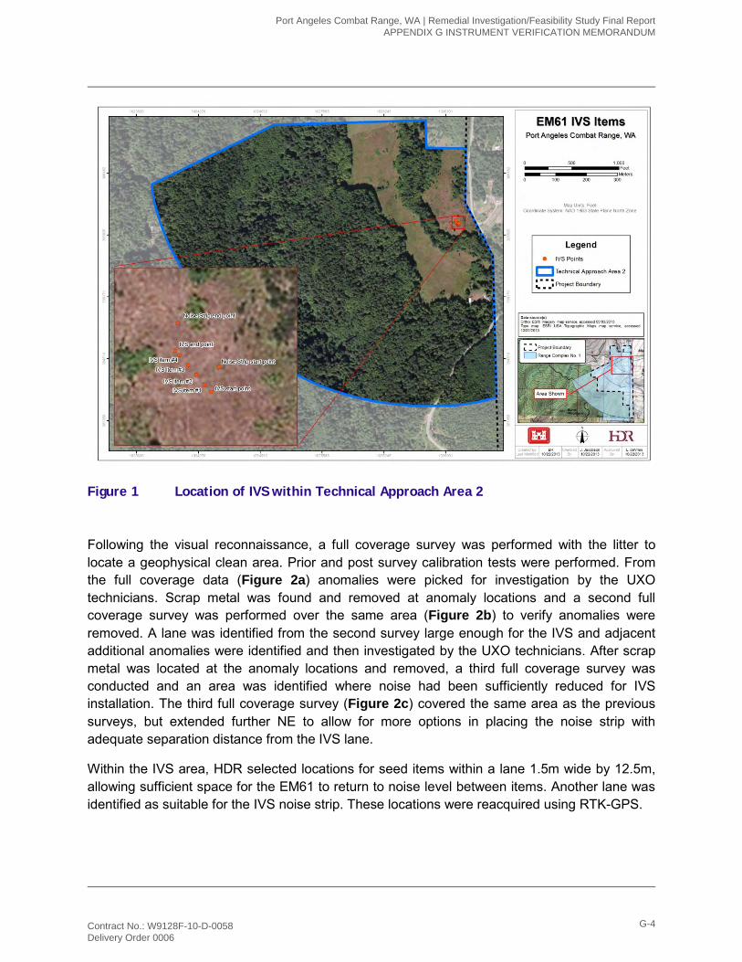
Figure 1 Location of IVS within Technical Approach Area 2
Following the visual reconnaissance, a full coverage survey was performed with the litter to locate a geophysical clean area. Prior and post survey calibration tests were performed. From the full coverage data (Figure 2a) anomalies were picked for investigation by the UXO technicians. Scrap metal was found and removed at anomaly locations and a second full coverage survey was performed over the same area (Figure 2b) to verify anomalies were removed. A lane was identified from the second survey large enough for the IVS and adjacent additional anomalies were identified and then investigated by the UXO technicians. After scrap metal was located at the anomaly locations and removed, a third full coverage survey was conducted and an area was identified where noise had been sufficiently reduced for IVS installation. The third full coverage survey (Figure 2c) covered the same area as the previous surveys, but extended further NE to allow for more options in placing the noise strip with adequate separation distance from the IVS lane.
Within the IVS area, HDR selected locations for seed items within a lane 1.5m wide by 12.5m, allowing sufficient space for the EM61 to return to noise level between items. Another lane was identified as suitable for the IVS noise strip. These locations were reacquired using RTK-GPS.
Port Angeles Combat Range, WA | Remedial Investigation/Feasibility Study Final Report APPENDIX G INSTRUMENT VERIFICATION MEMORANDUM
Contract No.: W9128F-10-D-0058 Delivery Order 0006
G-4
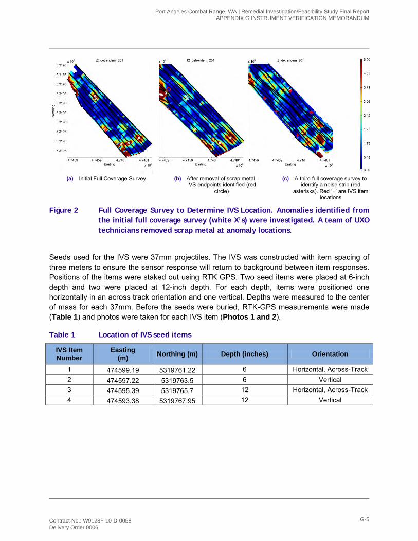
(a) Initial Full Coverage Survey (b) After removal of scrap metal. IVS endpoints identified (red
circle)
(c) A third full coverage survey to identify a noise strip (red
asterisks). Red ‘+’ are IVS item locations
Figure 2 Full Coverage Survey to Determine IVS Location. Anomalies identified from the initial full coverage survey (white X’s) were investigated. A team of UXO technicians removed scrap metal at anomaly locations.
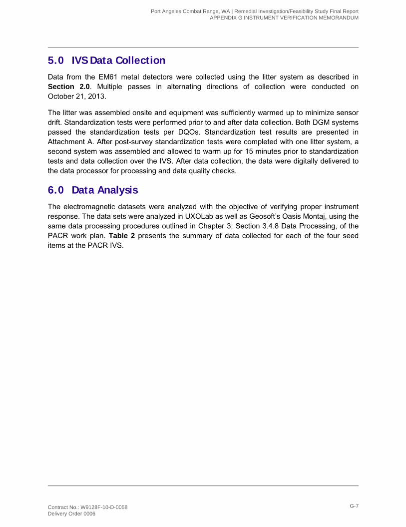
Seeds used for the IVS were 37mm projectiles. The IVS was constructed with item spacing of three meters to ensure the sensor response will return to background between item responses. Positions of the items were staked out using RTK GPS. Two seed items were placed at 6-inch depth and two were placed at 12-inch depth. For each depth, items were positioned one horizontally in an across track orientation and one vertical. Depths were measured to the center of mass for each 37mm. Before the seeds were buried, RTK-GPS measurements were made (Table 1) and photos were taken for each IVS item (Photos 1 and 2).
Table 1 Location of IVS seed items
IVS Item Number
Easting (m) Northing (m) Depth (inches) Orientation
1 474599.19 5319761.22 6 Horizontal, Across-Track 2 474597.22 5319763.5 6 Vertical 3 474595.39 5319765.7 12 Horizontal, Across-Track 4 474593.38 5319767.95 12 Vertical
Port Angeles Combat Range, WA | Remedial Investigation/Feasibility Study Final Report APPENDIX G INSTRUMENT VERIFICATION MEMORANDUM
Contract No.: W9128F-10-D-0058 Delivery Order 0006
G-5
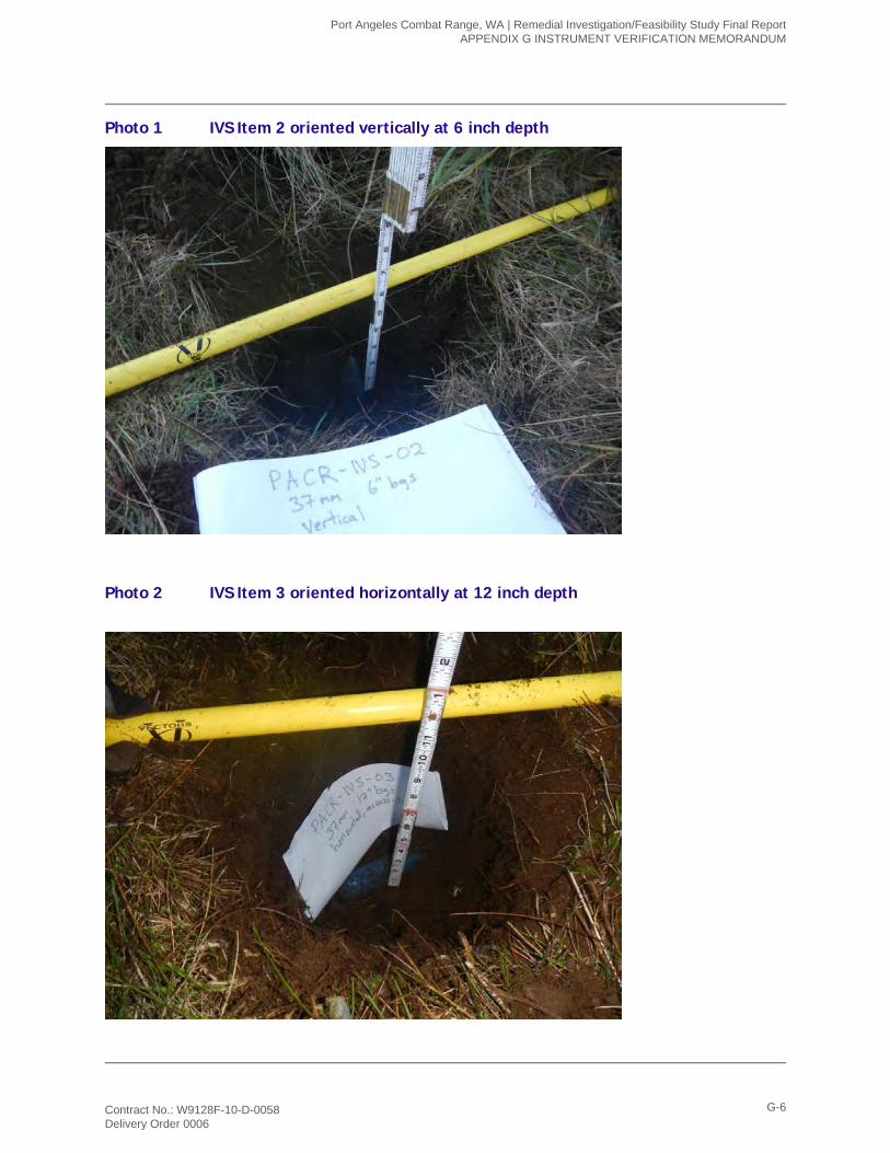
Photo 1 IVS Item 2 oriented vertically at 6 inch depth
Photo 2 IVS Item 3 oriented horizontally at 12 inch depth
Port Angeles Combat Range, WA | Remedial Investigation/Feasibility Study Final Report APPENDIX G INSTRUMENT VERIFICATION MEMORANDUM
Contract No.: W9128F-10-D-0058 Delivery Order 0006
G-6
5.0 IVS Data Collection Data from the EM61 metal detectors were collected using the litter system as described in Section 2.0. Multiple passes in alternating directions of collection were conducted on October 21, 2013.
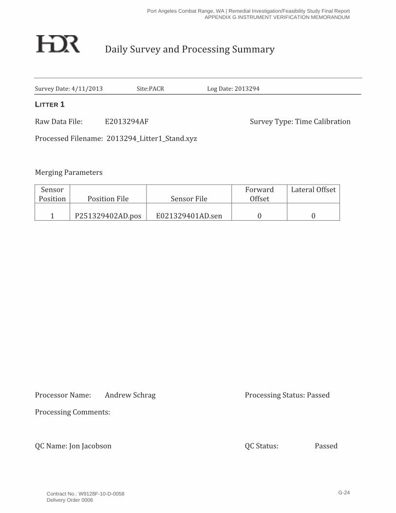
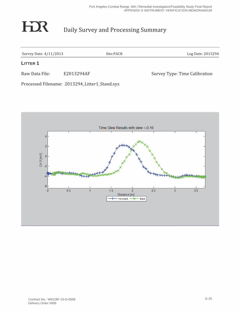
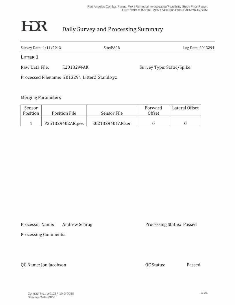
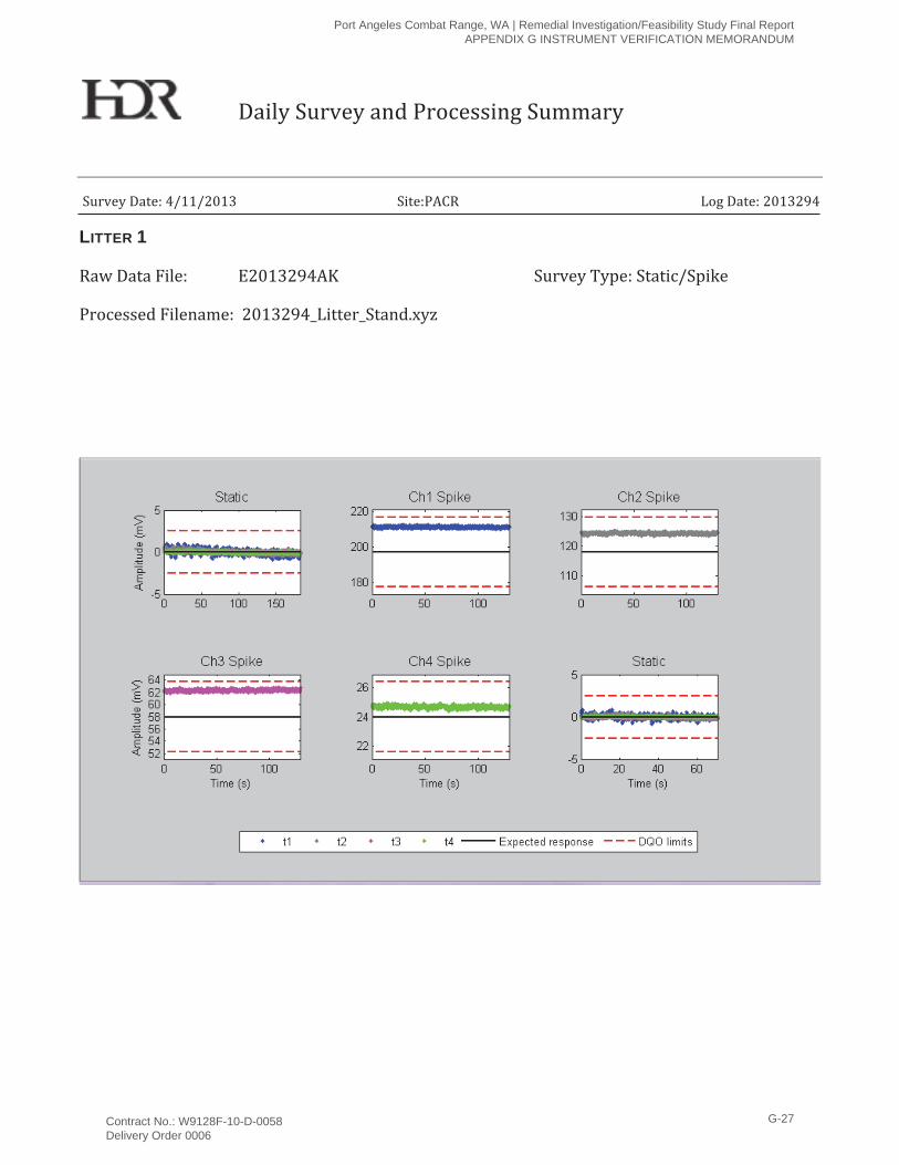
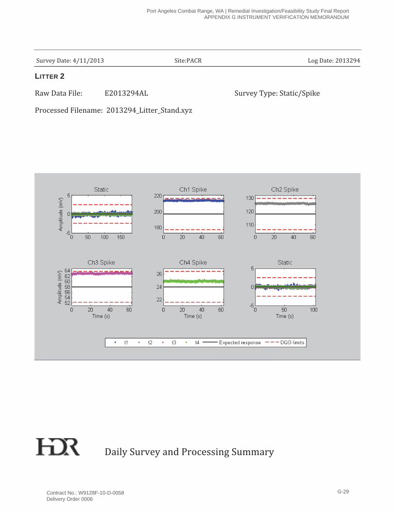
The litter was assembled onsite and equipment was sufficiently warmed up to minimize sensor drift. Standardization tests were performed prior to and after data collection. Both DGM systems passed the standardization tests per DQOs. Standardization test results are presented in Attachment A. After post-survey standardization tests were completed with one litter system, a second system was assembled and allowed to warm up for 15 minutes prior to standardization tests and data collection over the IVS. After data collection, the data were digitally delivered to the data processor for processing and data quality checks.
6.0 Data Analysis The electromagnetic datasets were analyzed with the objective of verifying proper instrument response. The data sets were analyzed in UXOLab as well as Geosoft’s Oasis Montaj, using the same data processing procedures outlined in Chapter 3, Section 3.4.8 Data Processing, of the PACR work plan. Table 2 presents the summary of data collected for each of the four seed items at the PACR IVS.
Port Angeles Combat Range, WA | Remedial Investigation/Feasibility Study Final Report APPENDIX G INSTRUMENT VERIFICATION MEMORANDUM
Contract No.: W9128F-10-D-0058 Delivery Order 0006
G-7
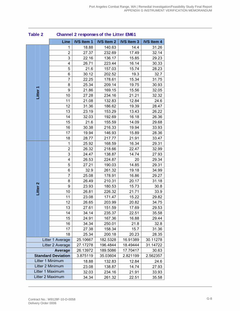
Table 2 Channel 2 responses of the Litter EM61
Line IVS Item 1 IVS Item 2 IVS Item 3 IVS Item 4 Li
tter 1
1 18.88 140.63 14.4 31.26 2 27.37 232.69 17.49 32.14 3 22.16 136.17 15.85 29.23 4 26.71 223.44 16.14 30.33 5 21.6 157.03 15.74 28.23 6 30.12 202.52 19.3 32.7 7 22.25 178.61 15.34 31.75 8 25.34 209.14 19.75 30.93 9 21.86 169.15 15.56 32.05
10 27.28 234.16 21.21 32.32 11 21.08 132.83 12.84 24.6 12 31.36 186.62 19.39 28.47 13 23.19 153.29 13.43 26.22 14 32.03 192.69 16.18 26.36 15 21.6 155.59 14.09 29.68 16 30.38 216.33 19.94 33.93 17 19.94 146.93 15.89 28.36 18 28.77 217.77 21.91 33.47
Litte
r 2
1 25.92 168.59 16.34 29.31 2 26.32 218.66 22.47 32.99 3 24.47 138.87 14.74 27.93 4 26.53 224.87 20 29.34 5 27.21 190.03 14.85 29.31 6 32.9 261.32 19.18 34.99 7 25.08 178.91 16.86 29.27 8 26.49 210.31 20.17 31.18 9 23.93 180.53 15.73 30.8
10 26.81 226.32 21.71 33.9 11 23.08 171.47 15.22 29.82 12 26.65 203.99 20.82 34.75 13 27.61 151.59 17.69 29.53 14 34.14 235.37 22.51 35.58 15 24.91 167.36 16.88 29.44 16 34.34 250.01 21.8 32.8 17 27.38 158.34 15.7 31.36 18 25.34 200.18 20.23 28.35
Litter 1 Average 25.10667 182.5328 16.91389 30.11278 Litter 2 Average 27.17278 196.4844 18.49444 31.14722
Average 26.13972 189.5086 17.70417 30.63 Standard Deviation 3.875119 35.03604 2.821199 2.562357 Litter 1 Minimum 18.88 132.83 12.84 24.6 Litter 2 Minimum 23.08 138.87 14.74 27.93 Litter 1 Maximum 32.03 234.16 21.91 33.93 Litter 2 Maximum 34.34 261.32 22.51 35.58
Port Angeles Combat Range, WA | Remedial Investigation/Feasibility Study Final Report APPENDIX G INSTRUMENT VERIFICATION MEMORANDUM
Contract No.: W9128F-10-D-0058 Delivery Order 0006
G-8
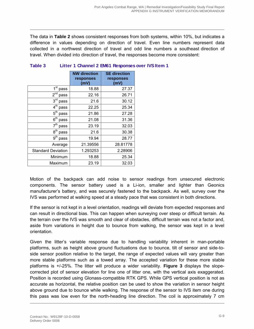
The data in Table 2 shows consistent responses from both systems, within 10%, but indicates a difference in values depending on direction of travel. Even line numbers represent data collected in a northwest direction of travel and odd line numbers a southeast direction of travel. When divided into direction of travel, the responses become more consistent:
Table 3 Litter 1 Channel 2 EM61 Responses over IVS Item 1
NW direction responses
(mV)
SE direction responses
(mV) 1st pass 18.88 27.37 2nd pass 22.16 26.71 3rd pass 21.6 30.12 4th pass 22.25 25.34 5th pass 21.86 27.28 6th pass 21.08 31.36 7th pass 23.19 32.03 8th pass 21.6 30.38 9th pass 19.94 28.77 Average 21.39556 28.81778
Standard Deviation 1.293253 2.28906 Minimum 18.88 25.34 Maximum 23.19 32.03
Motion of the backpack can add noise to sensor readings from unsecured electronic components. The sensor battery used is a Li-ion, smaller and lighter than Geonics manufacturer’s battery, and was securely fastened to the backpack. As well, survey over the IVS was performed at walking speed at a steady pace that was consistent in both directions.
If the sensor is not kept in a level orientation, readings will deviate from expected responses and can result in directional bias. This can happen when surveying over steep or difficult terrain. As the terrain over the IVS was smooth and clear of obstacles, difficult terrain was not a factor and, aside from variations in height due to bounce from walking, the sensor was kept in a level orientation.
Given the litter’s variable response due to handling variability inherent in man-portable platforms, such as height above ground fluctuations due to bounce, tilt of sensor and side-to-side sensor position relative to the target, the range of expected values will vary greater than more stable platforms such as a towed array. The accepted variation for these more stable platforms is +/-25%. The litter will produce a wider variability. Figure 3 displays the slope-corrected plot of sensor elevation for line one of litter one, with the vertical axis exaggerated. Position is recorded using Glonass-compatible RTK GPS. While GPS vertical position is not as accurate as horizontal, the relative position can be used to show the variation in sensor height above ground due to bounce while walking. The response of the sensor to IVS item one during this pass was low even for the north-heading line direction. The coil is approximately 7 cm
Port Angeles Combat Range, WA | Remedial Investigation/Feasibility Study Final Report APPENDIX G INSTRUMENT VERIFICATION MEMORANDUM
Contract No.: W9128F-10-D-0058 Delivery Order 0006
G-9
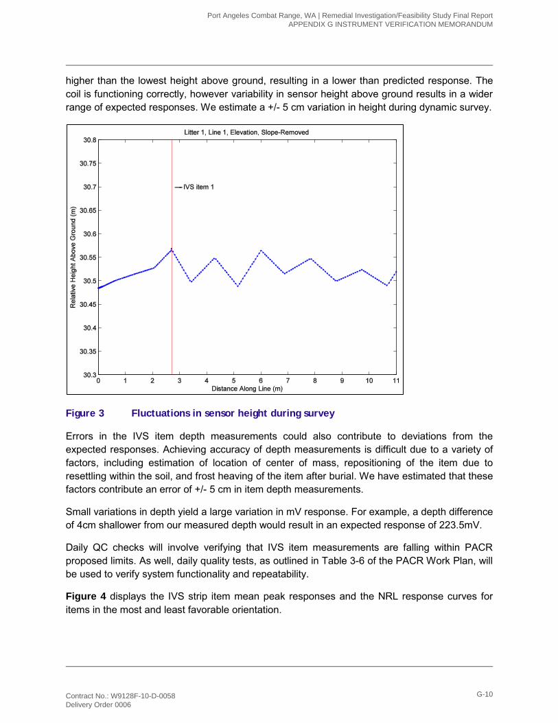
higher than the lowest height above ground, resulting in a lower than predicted response. The coil is functioning correctly, however variability in sensor height above ground results in a wider range of expected responses. We estimate a +/- 5 cm variation in height during dynamic survey.
Figure 3 Fluctuations in sensor height during survey
Errors in the IVS item depth measurements could also contribute to deviations from the expected responses. Achieving accuracy of depth measurements is difficult due to a variety of factors, including estimation of location of center of mass, repositioning of the item due to resettling within the soil, and frost heaving of the item after burial. We have estimated that these factors contribute an error of +/- 5 cm in item depth measurements.
Small variations in depth yield a large variation in mV response. For example, a depth difference of 4cm shallower from our measured depth would result in an expected response of 223.5mV.
Daily QC checks will involve verifying that IVS item measurements are falling within PACR proposed limits. As well, daily quality tests, as outlined in Table 3-6 of the PACR Work Plan, will be used to verify system functionality and repeatability.
Figure 4 displays the IVS strip item mean peak responses and the NRL response curves for items in the most and least favorable orientation.
Port Angeles Combat Range, WA | Remedial Investigation/Feasibility Study Final Report APPENDIX G INSTRUMENT VERIFICATION MEMORANDUM
Contract No.: W9128F-10-D-0058 Delivery Order 0006
G-10
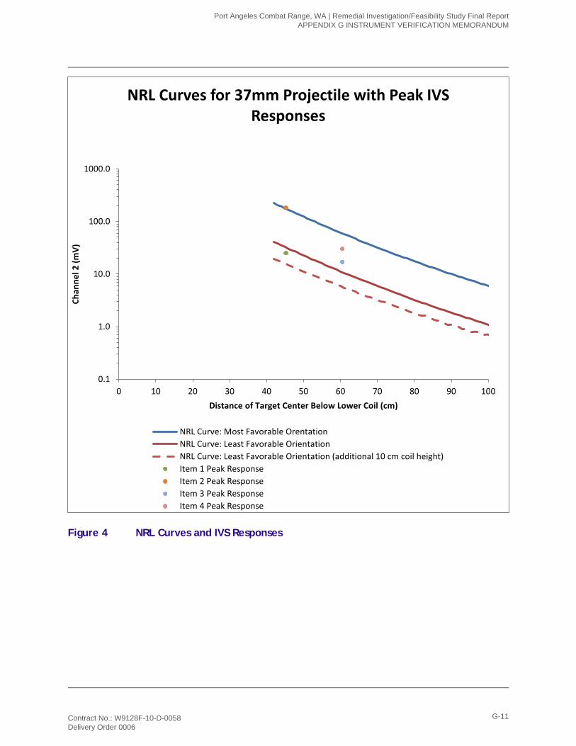
Figure 4 NRL Curves and IVS Responses
0.1
1.0
10.0
100.0
1000.0
0 10 20 30 40 50 60 70 80 90 100
Chan
nel 2
(mV)
Distance of Target Center Below Lower Coil (cm)
NRL Curves for 37mm Projectile with Peak IVS Responses
NRL Curve: Most Favorable OrentationNRL Curve: Least Favorable OrientationNRL Curve: Least Favorable Orientation (additional 10 cm coil height)Item 1 Peak ResponseItem 2 Peak ResponseItem 3 Peak ResponseItem 4 Peak Response
Port Angeles Combat Range, WA | Remedial Investigation/Feasibility Study Final Report APPENDIX G INSTRUMENT VERIFICATION MEMORANDUM
Contract No.: W9128F-10-D-0058 Delivery Order 0006
G-11
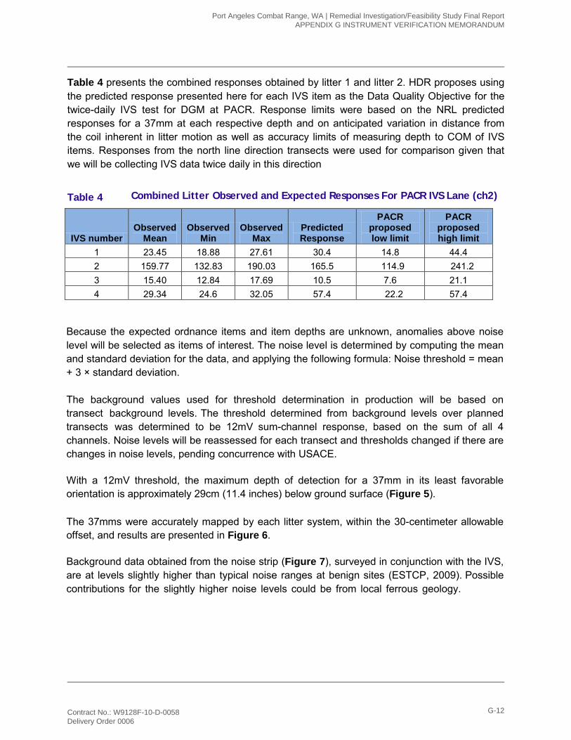
Table 4 presents the combined responses obtained by litter 1 and litter 2. HDR proposes using the predicted response presented here for each IVS item as the Data Quality Objective for the twice-daily IVS test for DGM at PACR. Response limits were based on the NRL predicted responses for a 37mm at each respective depth and on anticipated variation in distance from the coil inherent in litter motion as well as accuracy limits of measuring depth to COM of IVS items. Responses from the north line direction transects were used for comparison given that we will be collecting IVS data twice daily in this direction
The 37mms were accurately mapped by each litter system, within the 30-centimeter allowable offset, and results are presented in Figure 6.
Background data obtained from the noise strip (Figure 7), surveyed in conjunction with the IVS, are at levels slightly higher than typical noise ranges at benign sites (ESTCP, 2009). Possible contributions for the slightly higher noise levels could be from local ferrous geology.
Because the expected ordnance items and item depths are unknown, anomalies above noise level will be selected as items of interest. The noise level is determined by computing the mean and standard deviation for the data, and applying the following formula: Noise threshold = mean + 3 × standard deviation.
The background values used for threshold determination in production will be based on transect background levels. The threshold determined from background levels over planned transects was determined to be 12mV sum-channel response, based on the sum of all 4 channels. Noise levels will be reassessed for each transect and thresholds changed if there are changes in noise levels, pending concurrence with USACE.
With a 12mV threshold, the maximum depth of detection for a 37mm in its least favorable orientation is approximately 29cm (11.4 inches) below ground surface (Figure 5).
Table 4 Combined Litter Observed and Expected Responses For PACR IVS Lane (ch2)
IVS number Observed
Mean Observed
Min Observed
Max Predicted Response
PACR proposed low limit
PACR proposed high limit
1 23.45 18.88 27.61 30.4 14.8 44.4 2 159.77 132.83 190.03 165.5 114.9 241.2 3 15.40 12.84 17.69 10.5 7.6 21.1 4 29.34 24.6 32.05 57.4 22.2 57.4
Port Angeles Combat Range, WA | Remedial Investigation/Feasibility Study Final Report APPENDIX G INSTRUMENT VERIFICATION MEMORANDUM
Contract No.: W9128F-10-D-0058 Delivery Order 0006
G-12
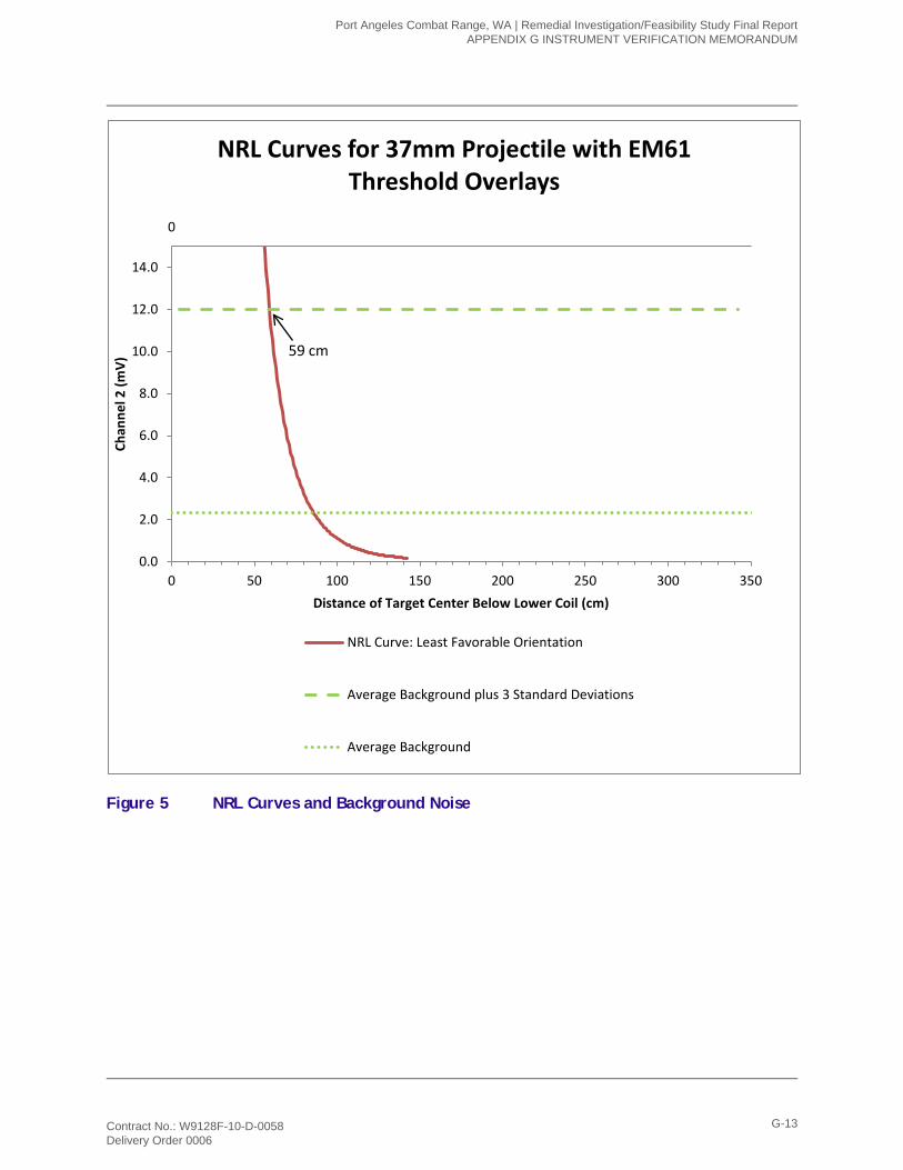
Figure 5 NRL Curves and Background Noise
0
0.0
2.0
4.0
6.0
8.0
10.0
12.0
14.0
0 50 100 150 200 250 300 350
Chan
nel 2
(mV)
Distance of Target Center Below Lower Coil (cm)
NRL Curves for 37mm Projectile with EM61 Threshold Overlays
NRL Curve: Least Favorable Orientation
Average Background plus 3 Standard Deviations
Average Background
59 cm
Port Angeles Combat Range, WA | Remedial Investigation/Feasibility Study Final Report APPENDIX G INSTRUMENT VERIFICATION MEMORANDUM
Contract No.: W9128F-10-D-0058 Delivery Order 0006
G-13
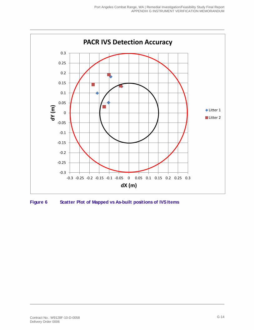
Figure 6 Scatter Plot of Mapped vs As-built positions of IVS Items
-0.3
-0.25
-0.2
-0.15
-0.1
-0.05
0
0.05
0.1
0.15
0.2
0.25
0.3
-0.3 -0.25 -0.2 -0.15 -0.1 -0.05 0 0.05 0.1 0.15 0.2 0.25 0.3
dY (m
)
dX (m)
PACR IVS Detection Accuracy
Litter 1
Litter 2
Port Angeles Combat Range, WA | Remedial Investigation/Feasibility Study Final Report APPENDIX G INSTRUMENT VERIFICATION MEMORANDUM
Contract No.: W9128F-10-D-0058 Delivery Order 0006
G-14
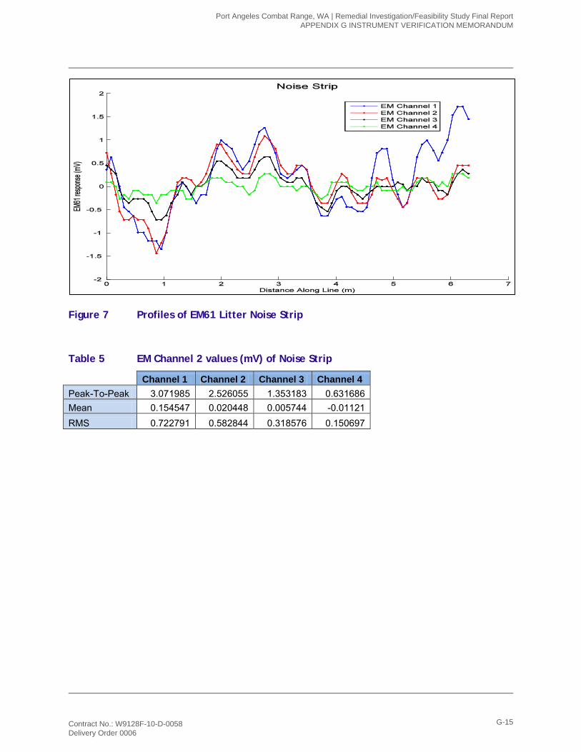
Figure 7 Profiles of EM61 Litter Noise Strip
Table 5 EM Channel 2 values (mV) of Noise Strip
Channel 1 Channel 2 Channel 3 Channel 4 Peak-To-Peak 3.071985 2.526055 1.353183 0.631686 Mean 0.154547 0.020448 0.005744 -0.01121 RMS 0.722791 0.582844 0.318576 0.150697
Port Angeles Combat Range, WA | Remedial Investigation/Feasibility Study Final Report APPENDIX G INSTRUMENT VERIFICATION MEMORANDUM
Contract No.: W9128F-10-D-0058 Delivery Order 0006
G-15

7.0 Conclusions and Recommendations Repeatability of sensor response verifies that both litter systems are functioning properly.
Responses over items fall within NRL most favorable and least favorable predicted responses.
Values obtained over the noise strip show that the conservative approach of selecting anomalies above noise will be appropriate given limitations of depth of detection.
Sensor responses should be reviewed daily to verify that responses are consistent within limits of PACR proposed limits.
Port Angeles Combat Range, WA | Remedial Investigation/Feasibility Study Final Report APPENDIX G INSTRUMENT VERIFICATION MEMORANDUM
Contract No.: W9128F-10-D-0058 Delivery Order 0006
G-16
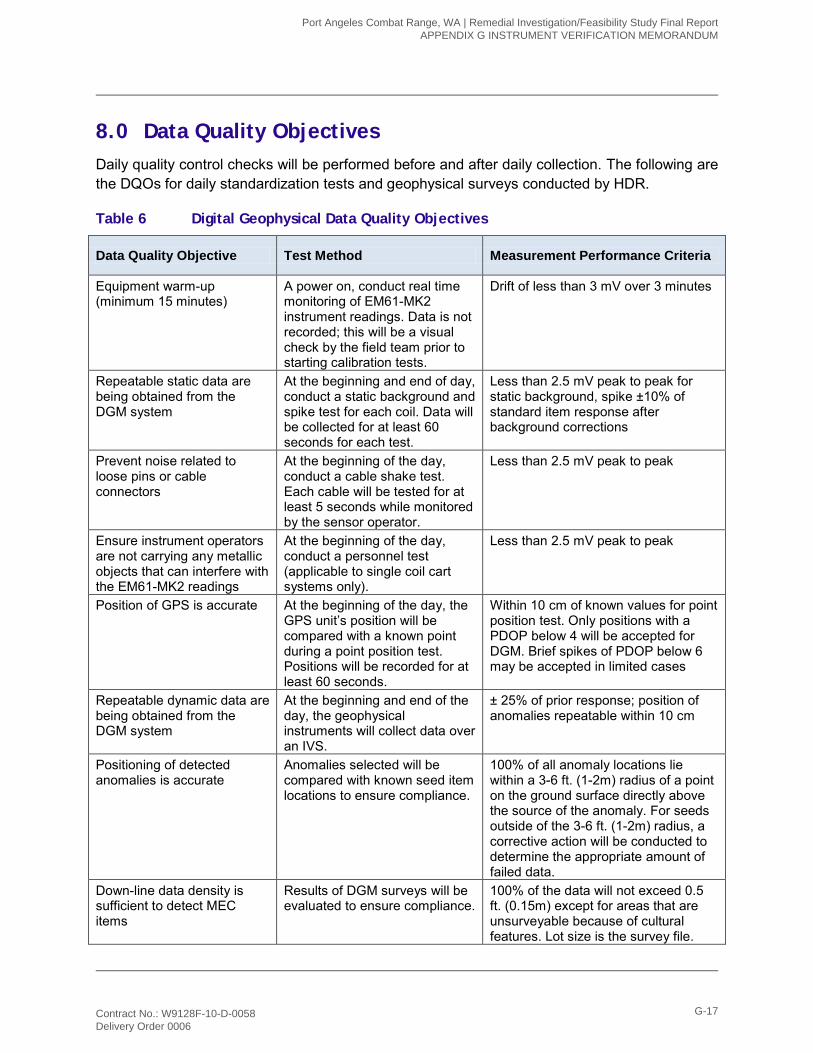
8.0 Data Quality Objectives Daily quality control checks will be performed before and after daily collection. The following are the DQOs for daily standardization tests and geophysical surveys conducted by HDR.
Table 6 Digital Geophysical Data Quality Objectives
Data Quality Objective Test Method Measurement Performance Criteria
Equipment warm-up (minimum 15 minutes)
A power on, conduct real time monitoring of EM61-MK2 instrument readings. Data is not recorded; this will be a visual check by the field team prior to starting calibration tests.
Drift of less than 3 mV over 3 minutes
Repeatable static data are being obtained from the DGM system
At the beginning and end of day, conduct a static background and spike test for each coil. Data will be collected for at least 60 seconds for each test.
Less than 2.5 mV peak to peak for static background, spike ±10% of standard item response after background corrections
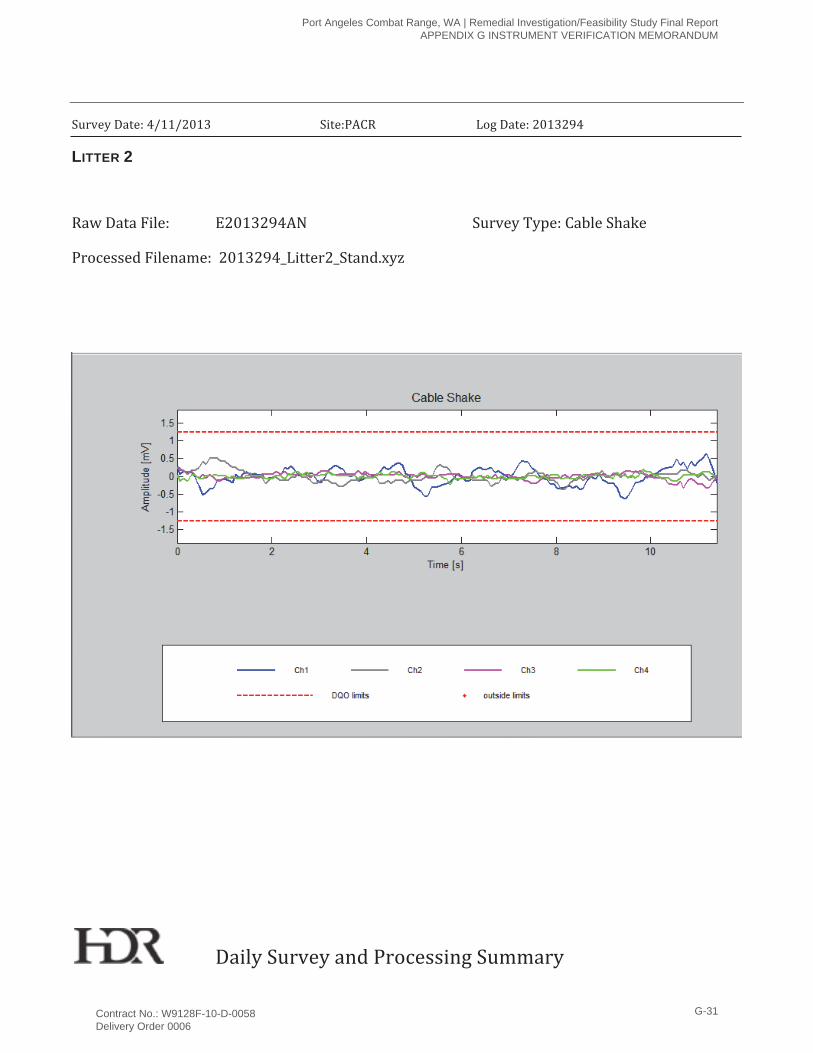
Prevent noise related to loose pins or cable connectors
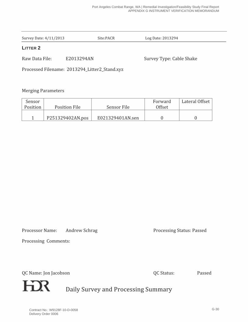
At the beginning of the day, conduct a cable shake test. Each cable will be tested for at least 5 seconds while monitored by the sensor operator.
Less than 2.5 mV peak to peak
Ensure instrument operators are not carrying any metallic objects that can interfere with the EM61-MK2 readings
At the beginning of the day, conduct a personnel test (applicable to single coil cart systems only).
Less than 2.5 mV peak to peak
Position of GPS is accurate At the beginning of the day, the GPS unit’s position will be compared with a known point during a point position test. Positions will be recorded for at least 60 seconds.
Within 10 cm of known values for point position test. Only positions with a PDOP below 4 will be accepted for DGM. Brief spikes of PDOP below 6 may be accepted in limited cases
Repeatable dynamic data are being obtained from the DGM system
At the beginning and end of the day, the geophysical instruments will collect data over an IVS.
± 25% of prior response; position of anomalies repeatable within 10 cm
Positioning of detected anomalies is accurate
Anomalies selected will be compared with known seed item locations to ensure compliance.
100% of all anomaly locations lie within a 3-6 ft. (1-2m) radius of a point on the ground surface directly above the source of the anomaly. For seeds outside of the 3-6 ft. (1-2m) radius, a corrective action will be conducted to determine the appropriate amount of failed data.
Down-line data density is sufficient to detect MEC items
Results of DGM surveys will be evaluated to ensure compliance.
100% of the data will not exceed 0.5 ft. (0.15m) except for areas that are unsurveyable because of cultural features. Lot size is the survey file.
Port Angeles Combat Range, WA | Remedial Investigation/Feasibility Study Final Report APPENDIX G INSTRUMENT VERIFICATION MEMORANDUM
Contract No.: W9128F-10-D-0058 Delivery Order 0006
G-17

Data Quality Objective Test Method Measurement Performance Criteria
Consistent detection of blind seed items during dynamic survey
Transects with fixed RTK GPS coverage will be seeded with ISOs or seed items and surveyed by geophysical personnel.
95% of the ISOs or seed items will be detected. Any misses will results in a root cause analysis and may result in a resurvey of all or a portion of the transect.
Port Angeles Combat Range, WA | Remedial Investigation/Feasibility Study Final Report APPENDIX G INSTRUMENT VERIFICATION MEMORANDUM
Contract No.: W9128F-10-D-0058 Delivery Order 0006
G-18

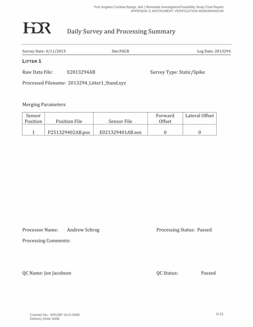
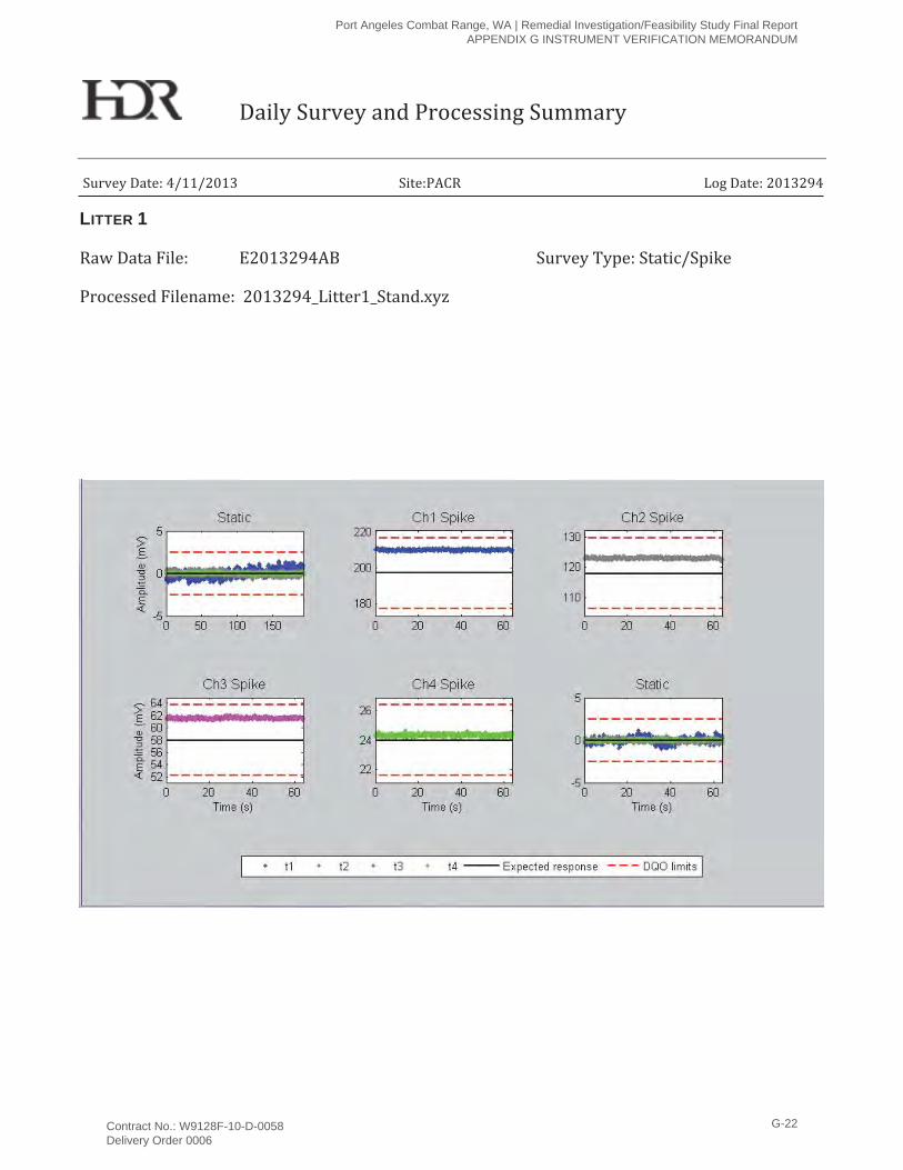
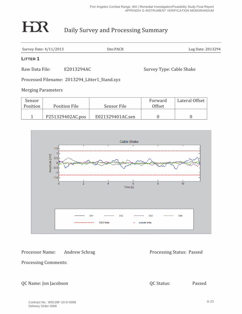
Attachment A Daily Survey and Processing Summary
Attachment A
Daily Survey and Processing Summary
Port Angeles Combat Range, WA | Remedial Investigation/Feasibility Study Final Report APPENDIX G INSTRUMENT VERIFICATION MEMORANDUM
Contract No.: W9128F-10-D-0058 Delivery Order 0006
G-19

Port Angeles Combat Range, WA | Remedial Investigation/Feasibility Study Final Report APPENDIX G INSTRUMENT VERIFICATION MEMORANDUM
Contract No.: W9128F-10-D-0058 Delivery Order 0006
G-20
LITTER 1
Port Angeles Combat Range, WA | Remedial Investigation/Feasibility Study Final Report APPENDIX G INSTRUMENT VERIFICATION MEMORANDUM
Contract No.: W9128F-10-D-0058 Delivery Order 0006
G-21
LITTER 1
Port Angeles Combat Range, WA | Remedial Investigation/Feasibility Study Final Report APPENDIX G INSTRUMENT VERIFICATION MEMORANDUM
Contract No.: W9128F-10-D-0058 Delivery Order 0006
G-22
LITTER 1
Port Angeles Combat Range, WA | Remedial Investigation/Feasibility Study Final Report APPENDIX G INSTRUMENT VERIFICATION MEMORANDUM
Contract No.: W9128F-10-D-0058 Delivery Order 0006
G-23
LITTER 1
Port Angeles Combat Range, WA | Remedial Investigation/Feasibility Study Final Report APPENDIX G INSTRUMENT VERIFICATION MEMORANDUM
Contract No.: W9128F-10-D-0058 Delivery Order 0006
G-24
LITTER 1
Port Angeles Combat Range, WA | Remedial Investigation/Feasibility Study Final Report APPENDIX G INSTRUMENT VERIFICATION MEMORANDUM
Contract No.: W9128F-10-D-0058 Delivery Order 0006
G-25
LITTER 1
Port Angeles Combat Range, WA | Remedial Investigation/Feasibility Study Final Report APPENDIX G INSTRUMENT VERIFICATION MEMORANDUM
Contract No.: W9128F-10-D-0058 Delivery Order 0006
G-26
LITTER 1
Port Angeles Combat Range, WA | Remedial Investigation/Feasibility Study Final Report APPENDIX G INSTRUMENT VERIFICATION MEMORANDUM
Contract No.: W9128F-10-D-0058 Delivery Order 0006
G-27
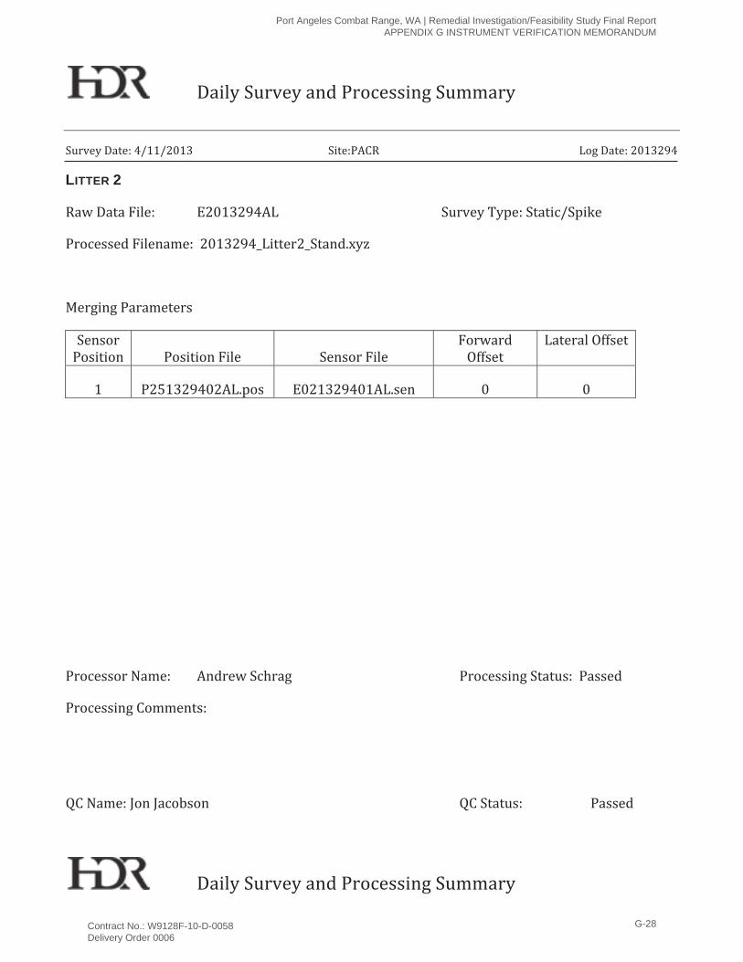
LITTER 2
Port Angeles Combat Range, WA | Remedial Investigation/Feasibility Study Final Report APPENDIX G INSTRUMENT VERIFICATION MEMORANDUM
Contract No.: W9128F-10-D-0058 Delivery Order 0006
G-28
LITTER 2
Port Angeles Combat Range, WA | Remedial Investigation/Feasibility Study Final Report APPENDIX G INSTRUMENT VERIFICATION MEMORANDUM
Contract No.: W9128F-10-D-0058 Delivery Order 0006
G-29
LITTER 2
Port Angeles Combat Range, WA | Remedial Investigation/Feasibility Study Final Report APPENDIX G INSTRUMENT VERIFICATION MEMORANDUM
Contract No.: W9128F-10-D-0058 Delivery Order 0006
G-30
LITTER 2
Port Angeles Combat Range, WA | Remedial Investigation/Feasibility Study Final Report APPENDIX G INSTRUMENT VERIFICATION MEMORANDUM
Contract No.: W9128F-10-D-0058 Delivery Order 0006
G-31
LITTER 2
Port Angeles Combat Range, WA | Remedial Investigation/Feasibility Study Final Report APPENDIX G INSTRUMENT VERIFICATION MEMORANDUM
Contract No.: W9128F-10-D-0058 Delivery Order 0006
G-32
LITTER 2
Port Angeles Combat Range, WA | Remedial Investigation/Feasibility Study Final Report APPENDIX G INSTRUMENT VERIFICATION MEMORANDUM
Contract No.: W9128F-10-D-0058 Delivery Order 0006
G-33
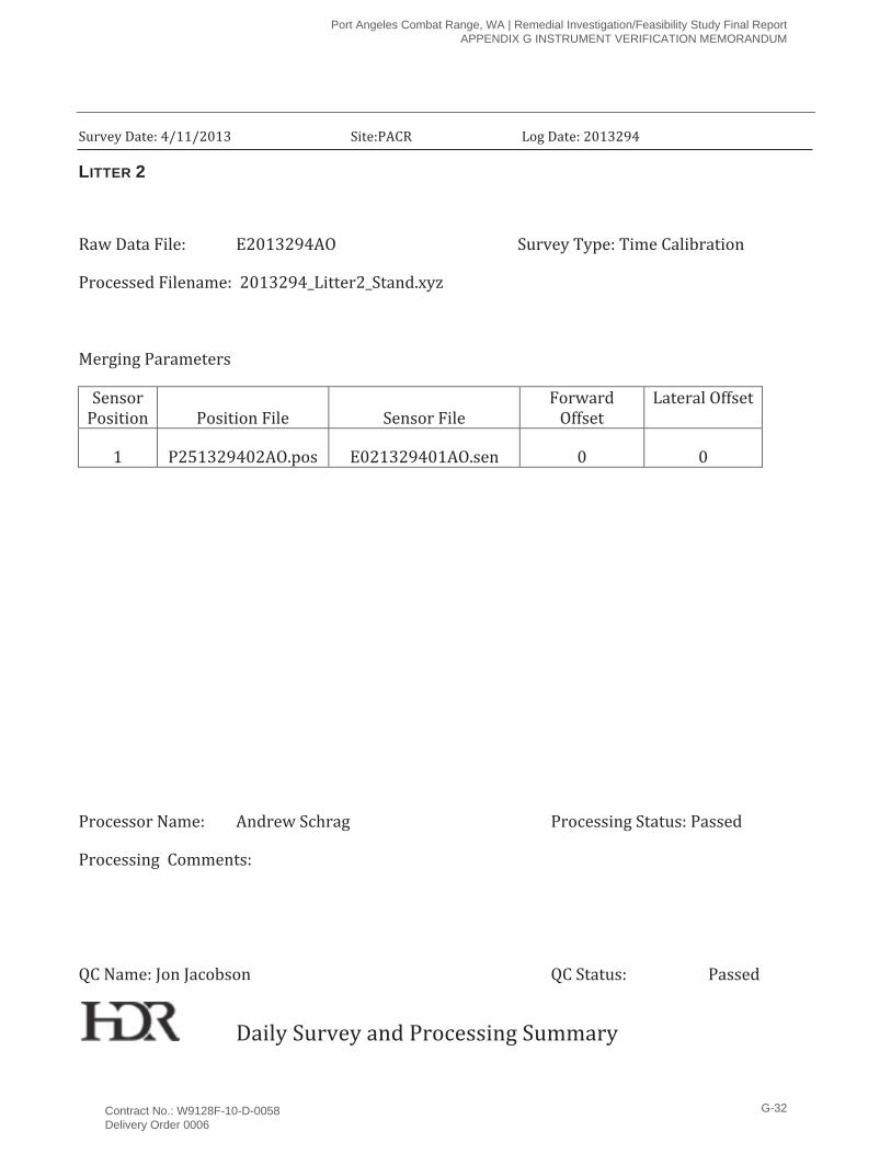
LITTER 2
Port Angeles Combat Range, WA | Remedial Investigation/Feasibility Study Final Report APPENDIX G INSTRUMENT VERIFICATION MEMORANDUM
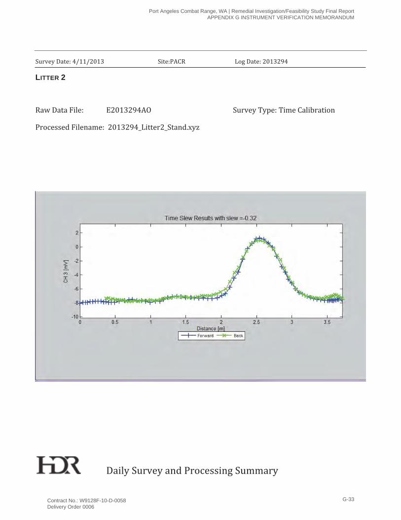
Contract No.: W9128F-10-D-0058 Delivery Order 0006
G-34
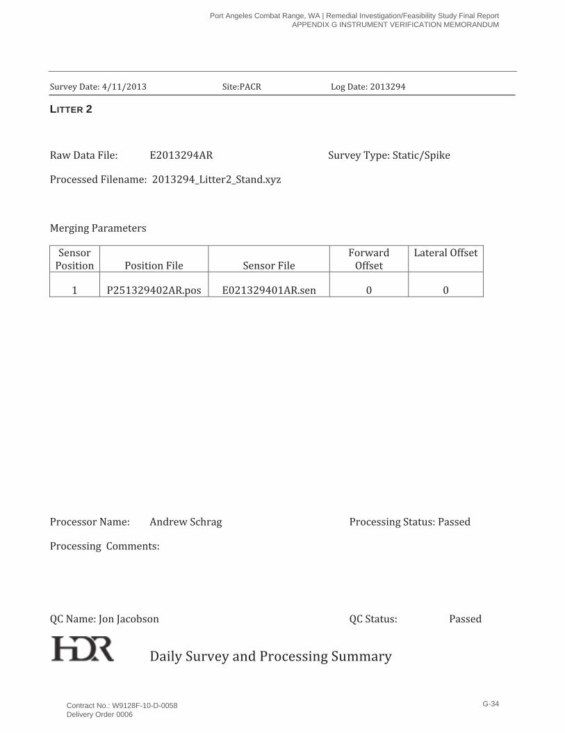
LITTER 2
Port Angeles Combat Range, WA | Remedial Investigation/Feasibility Study Final Report APPENDIX G INSTRUMENT VERIFICATION MEMORANDUM
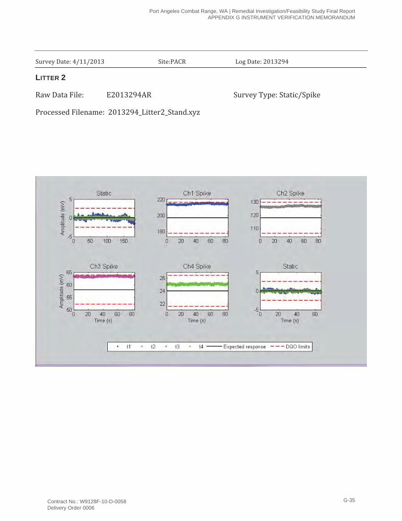
Contract No.: W9128F-10-D-0058 Delivery Order 0006
G-35

This page intentionally left blank.
Port Angeles Combat Range, WA | Remedial Investigation/Feasibility Study Final Report APPENDIX G INSTRUMENT VERIFICATION MEMORANDUM
Contract No.: W9128F-10-D-0058 Delivery Order 0006
G-36
Port Angeles Combat Range, WA | Remedial Investigation/Feasibility Study Final Report APPENDIX H ORDNANCE TECHNICAL DATA SHEETS
APPENDIX H
Ordnance Technical Data Sheets

Port Angeles Combat Range, WA | Remedial Investigation/Feasibility Study Final Report APPENDIX H ORDNANCE TECHNICAL DATA SHEETS
This page intentionally left blank.
� � � � � � � � � � � � � � � � � � � � � � � � � � � � � � � � � � � � � � � � � �
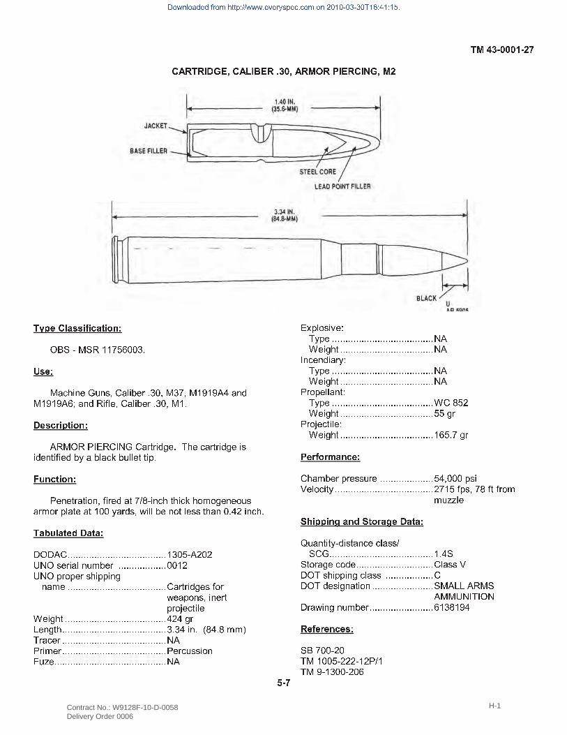
� � � � � � � � � � � � � � ! " #$ % & ' ( & ) * * + , - . . / 01 � � #( 2 3 4 5 6 7 8 9 6 : ; < 2 = 5 > 7 ? 0 / . ; ( / + ; ( * @ * @ A B 2 6 C( * @ * @ A - D 2 6 C ) 5 E = 7 ; < 2 = 5 > 7 ? 0 / . ; ( * 0 � � � F � � � ! " #A ) ( $ ) G H I ) < H J 8 < 2 ? K ? 5 C L 7 0 M 4 7 3 2 ? K ? 5 C L 7 5 :5 C 7 6 K 5 E 5 7 C > N 2 > = 2 3 O > 9 = = 7 K K 5 P 0Q R " � � ! " #G 7 6 7 K ? 2 K 5 S 6 ; E 5 ? 7 C 2 K + T U ' 5 6 3 4 K 4 5 3 O 4 S V S L 7 6 7 S 9 :2 ? V S ? P = 2 K 7 2 K * . . N 2 ? C : ; W 5 = = > 7 6 S K = 7 : : K 4 2 6 . 0 B X 5 6 3 4 0� � Y R � � � Z � � #[ $ [ A < 0 0 0 0 0 0 0 0 0 0 0 0 0 0 0 0 0 0 0 0 0 0 0 0 0 0 0 0 0 0 0 0 0 0 0 0 0 * / . , ' A X . X\ J $ : 7 ? 5 2 = 6 9 V > 7 ? 0 0 0 0 0 0 0 0 0 0 0 0 0 0 0 0 0 0 . . * X\ J $ P ? S P 7 ? : 4 5 P P 5 6 L6 2 V 7 0 0 0 0 0 0 0 0 0 0 0 0 0 0 0 0 0 0 0 0 0 0 0 0 0 0 0 0 0 0 0 0 0 0 0 0 0 < 2 ? K ? 5 C L 7 : E S ?W 7 2 P S 6 : ; 5 6 7 ? KP ? S ] 7 3 K 5 = 7^ 7 5 L 4 K 0 0 0 0 0 0 0 0 0 0 0 0 0 0 0 0 0 0 0 0 0 0 0 0 0 0 0 0 0 0 0 0 0 0 0 0 0 0 B X B L ?_ 7 6 L K 4 0 0 0 0 0 0 0 0 0 0 0 0 0 0 0 0 0 0 0 0 0 0 0 0 0 0 0 0 0 0 0 0 0 0 0 0 0 0 0 / 0 / B 5 6 0 ` U B 0 U V V aM ? 2 3 7 ? 0 0 0 0 0 0 0 0 0 0 0 0 0 0 0 0 0 0 0 0 0 0 0 0 0 0 0 0 0 0 0 0 0 0 0 0 0 0 0 J AG ? 5 V 7 ? 0 0 0 0 0 0 0 0 0 0 0 0 0 0 0 0 0 0 0 0 0 0 0 0 0 0 0 0 0 0 0 0 0 0 0 0 0 0 0 G 7 ? 3 9 : : 5 S 6b 9 c 7 0 0 0 0 0 0 0 0 0 0 0 0 0 0 0 0 0 0 0 0 0 0 0 0 0 0 0 0 0 0 0 0 0 0 0 0 0 0 0 0 0 0 J A
I d P = S : 5 e 7 fM N P 7 0 0 0 0 0 0 0 0 0 0 0 0 0 0 0 0 0 0 0 0 0 0 0 0 0 0 0 0 0 0 0 0 0 0 0 0 0 0 J A^ 7 5 L 4 K 0 0 0 0 0 0 0 0 0 0 0 0 0 0 0 0 0 0 0 0 0 0 0 0 0 0 0 0 0 0 0 0 0 0 0 J AH 6 3 7 6 C 5 2 ? N fM N P 7 0 0 0 0 0 0 0 0 0 0 0 0 0 0 0 0 0 0 0 0 0 0 0 0 0 0 0 0 0 0 0 0 0 0 0 0 0 0 J A^ 7 5 L 4 K 0 0 0 0 0 0 0 0 0 0 0 0 0 0 0 0 0 0 0 0 0 0 0 0 0 0 0 0 0 0 0 0 0 0 0 J AG ? S P 7 = = 2 6 K fM N P 7 0 0 0 0 0 0 0 0 0 0 0 0 0 0 0 0 0 0 0 0 0 0 0 0 0 0 0 0 0 0 0 0 0 0 0 0 0 0 ^ < U , X^ 7 5 L 4 K 0 0 0 0 0 0 0 0 0 0 0 0 0 0 0 0 0 0 0 0 0 0 0 0 0 0 0 0 0 0 0 0 0 0 0 , , L ?G ? S ] 7 3 K 5 = 7 f^ 7 5 L 4 K 0 0 0 0 0 0 0 0 0 0 0 0 0 0 0 0 0 0 0 0 0 0 0 0 0 0 0 0 0 0 0 0 0 0 0 * - , 0 + L ?� � F � ! F g � " � � #< 4 2 V > 7 ? P ? 7 : : 9 ? 7 0 0 0 0 0 0 0 0 0 0 0 0 0 0 0 0 0 0 0 0 , B ; . . . P : 5h 7 = S 3 5 K N 0 0 0 0 0 0 0 0 0 0 0 0 0 0 0 0 0 0 0 0 0 0 0 0 0 0 0 0 0 0 0 0 0 0 0 0 0 X + * , E P : ; + U E K E ? S VV 9 c c = 7i j � � � � " k � " Z i ! F � k � � � #l 9 2 6 K 5 K N ' C 5 : K 2 6 3 7 3 = 2 : : T& < 8 0 0 0 0 0 0 0 0 0 0 0 0 0 0 0 0 0 0 0 0 0 0 0 0 0 0 0 0 0 0 0 0 0 0 0 0 0 0 0 * 0 B && K S ? 2 L 7 3 S C 7 0 0 0 0 0 0 0 0 0 0 0 0 0 0 0 0 0 0 0 0 0 0 0 0 0 0 0 0 0 < = 2 : : h[ $ M : 4 5 P P 5 6 L 3 = 2 : : 0 0 0 0 0 0 0 0 0 0 0 0 0 0 0 0 0 0 <[ $ M C 7 : 5 L 6 2 K 5 S 6 0 0 0 0 0 0 0 0 0 0 0 0 0 0 0 0 0 0 0 0 0 0 0 & ( A _ _ A ) ( &A ( ( \ J H M H $ J[ ? 2 W 5 6 L 6 9 V > 7 ? 0 0 0 0 0 0 0 0 0 0 0 0 0 0 0 0 0 0 0 0 0 0 0 0 - * / U * @ B� � � � F � " � � � #& % + . . ' X .M ( * . . , ' X X X ' * X G T *M ( @ ' * / . . ' X . -m � �
n o p q r o s t u t v w o x y z z { | } } p p p ~ u � u w � � { u � ~ � o x o q � � � � � � � � � � � � � | � � | � � ~
Contract No.: W9128F-10-D-0058 Delivery Order 0006
H-1
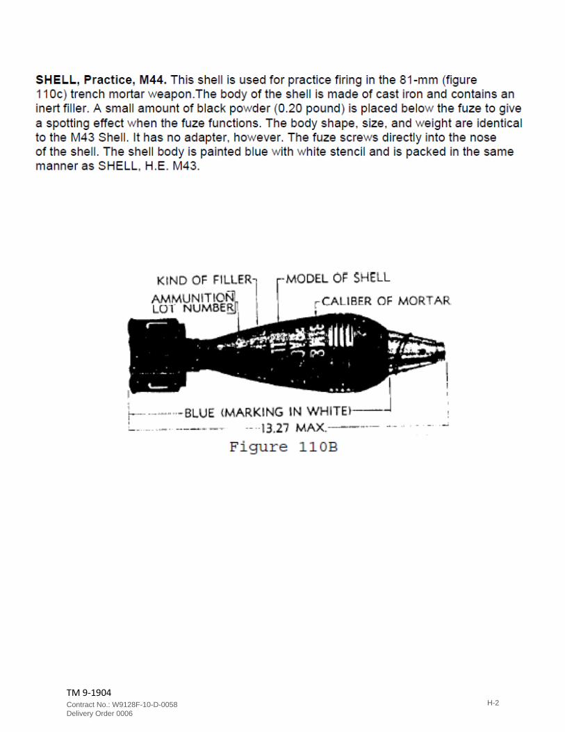
TM 9-1904
Contract No.: W9128F-10-D-0058 Delivery Order 0006
H-2
TM 43-0001-28
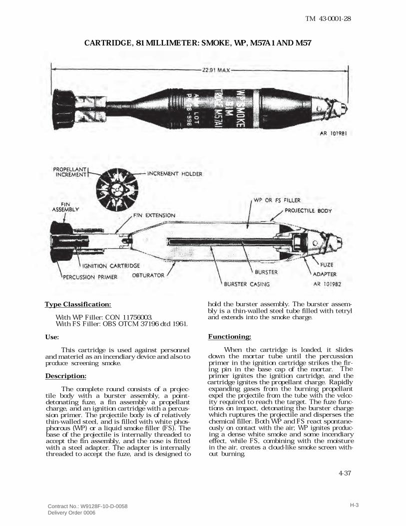
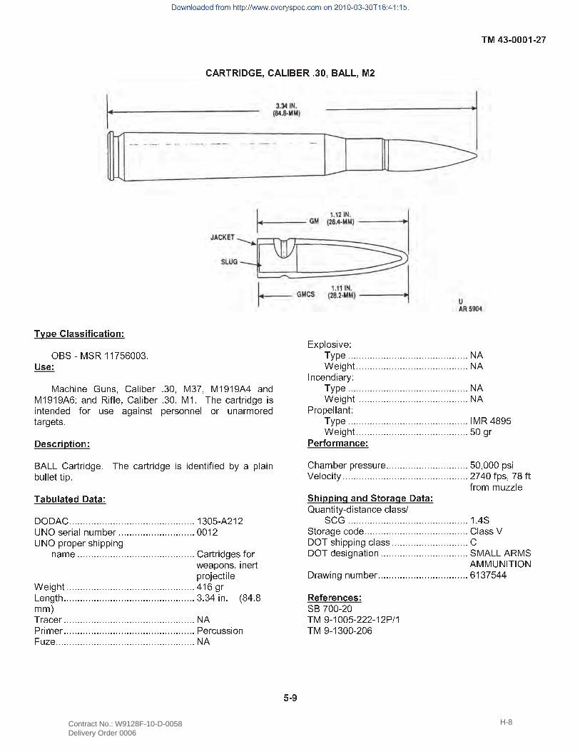
CARTRIDGE, 81 MILLIMETER: SMOKE, WP, M57A1 AND M57
Type Classification:With WP Filler: CON 11756003.With FS Filler: OBS OTCM 37196 dtd 1961.
Use:This cartridge is used against personneland materiel as an incendiary device and also toproduce screening smoke.
Description:The complete round consists of a projec-tile body with a burster assembly, a point-detonating fuze, a fin assembly a propellantcharge, and an ignition cartridge with a percus-sion primer. The projectile body is of relativelythin-walled steel, and is filled with white phos-phorous (WP) or a liquid smoke filler (FS). Thebase of the projectile is internally threaded toaccept the fin assembly, and the nose is fittedwith a steel adapter. The adapter is internallythreaded to accept the fuze, and is designed to
hold the burster assembly. The burster assem-bly is a thin-walled steel tube filled with tetryland extends into the smoke charge.Functioning:
When the cartridge is loaded, it slidesdown the mortar tube until the percussionprimer in the ignition cartridge strikes the fir-ing pin in the base cap of the mortar. Theprimer ignites the ignition cartridge, and thecartridge ignites the propellant charge. Rapidlyexpanding gases from the burning propellantexpel the projectile from the tube with the veloc-ity required to reach the target. The fuze func-tions on impact, detonating the burster chargewhich ruptures the projectile and disperses thechemical filler. Both WP and FS react spontane-ously on contact with the air; WP ignites produc-ing a dense white smoke and some incendiaryeffect, while FS, combining with the moisturein the air, creates a cloud-like smoke screen with-out burning.4-37
Contract No.: W9128F-10-D-0058 Delivery Order 0006
H-3
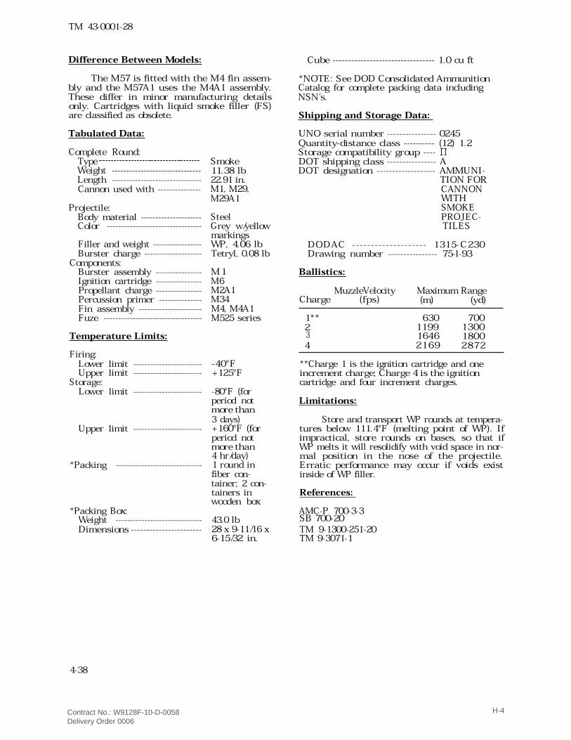
TM 43-0001-28Difference Between Models:
The M57 is fitted with the M4 fin assem-bly and the M57A1 uses the M4A1 assembly.These differ in minor manufacturing detailsonly. Cartridges with liquid smoke filler (FS)are classified as obsolete.Tabulated Data:Complete Round:Type � � � � � � � � � � � � � � � � � � � � � � � � � � � � � � � � � � �Weight -------------------------------Length -------------------------------Cannon used with ---------------Projectile:Body material ---------------------Color ---------------------------------
Filler and weight -----------------Burster charge --------------------Components:Burster assembly ----------------Ignition cartridge ----------------Propellant charge ----------------Percussion primer ---------------Fin assembly ----------------------Fuze ----------------------------------Temperature Limits:Firing:Lower limit ------------------------Upper limit ------------------------Storage:Lower limit ------------------------
Upper limit ------------------------
*Packing ------------------------------
*Packing Box:Weight ------------------------------Dimensions -----------------------
Smoke11.38 lb22.91 in.M1, M29,M29A1SteelGrey w/yellowmarkingsWP, 4.06 lbTetryl, 0.08 lbM 1M6M2A1M34M4, M4A1M525 series
-40°F+125°F-80°F (forperiod notmore than3 days)+160°F (forperiod notmore than4 hr/day)1 round infiber con-tainer; 2 con-tainers inwooden box43.0 lb28 x 9-11/16 x6-15/32 in.
Cube --------------------------------- 1.0 cu ft*NOTE: See DOD Consolidated AmmunitionCatalog for complete packing data includingNSN’s.Shipping and Storage Data:UNO serial number ---------------- 0245Quantity-distance class ---------- (12) 1.2Storage compatibility group ---- �DOT shipping class ---------------- ADOT designation ------------------- AMMUNI-TION FORCANNONWITHSMOKEPROJEC-TILES
DODAC -------------------- 1315-C230Drawing number ---------------- 75-l-93Ballistics:
MuzzleVelocity Maximum RangeCharge (m) (yd)1** 630 7002 1199 13001646 18004 2169 2872
**Charge 1 is the ignition cartridge and oneincrement charge; Charge 4 is the ignitioncartridge and four increment charges.Limitations:
Store and transport WP rounds at tempera-tures below 111.4°F (melting point of WP). Ifimpractical, store rounds on bases, so that ifWP melts it will resolidify with void space in nor-mal position in the nose of the projectile.Erratic performance may occur if voids existinside of WP filler.References:AMC-P 700-3-3TM 9-1300-251-20TM 9-3071-1
4-38
(fps)
3
SB 700-20
Contract No.: W9128F-10-D-0058 Delivery Order 0006
H-4
TM 43-0001-28
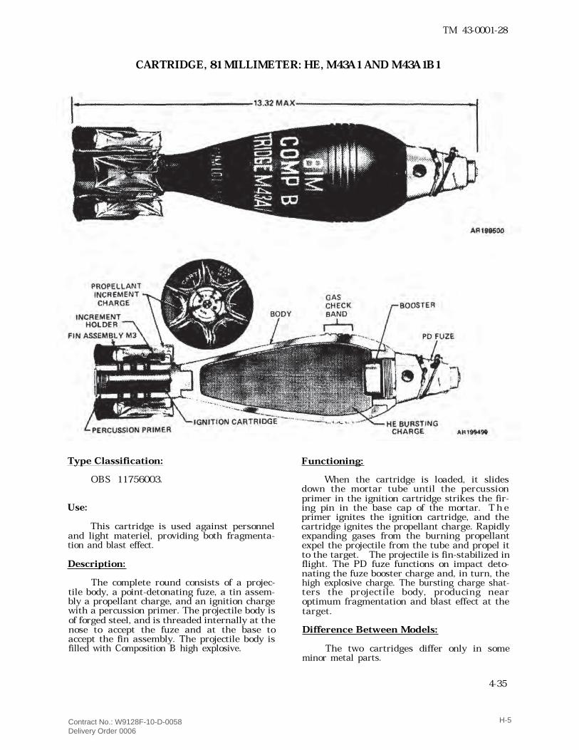
CARTRIDGE, 81 MILLIMETER: HE, M43A1 AND M43A1B1
Type Classification:OBS 11756003.
Use:This cartridge is used against personneland light materiel, providing both fragmenta-tion and blast effect.
Description:The complete round consists of a projec-tile body, a point-detonating fuze, a tin assem-bly a propellant charge, and an ignition chargewith a percussion primer. The projectile body isof forged steel, and is threaded internally at thenose to accept the fuze and at the base toaccept the fin assembly. The projectile body isfilled with Composition B high explosive.
Functioning:When the cartridge is loaded, it slidesdown the mortar tube until the percussionprimer in the ignition cartridge strikes the fir-ing pin in the base cap of the mortar. T h eprimer ignites the ignition cartridge, and thecartridge ignites the propellant charge. Rapidlyexpanding gases from the burning propellantexpel the projectile from the tube and propel itto the target. The projectile is fin-stabilized inflight. The PD fuze functions on impact deto-nating the fuze booster charge and, in turn, thehigh explosive charge. The bursting charge shat-ters the projectile body, producing nearoptimum fragmentation and blast effect at thetarget.
Difference Between Models:The two cartridges differ only in someminor metal parts.
4-35
Contract No.: W9128F-10-D-0058 Delivery Order 0006
H-5
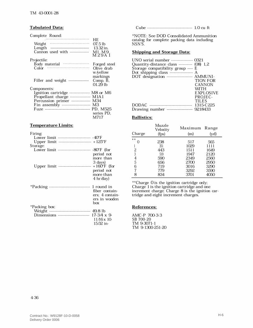
TM 43-0001-28Tabulated Data: Cube --------------------------------- 1.0 cu ftComplete Round:. - - - - - - - - - - - - - - - - - - - - - - - - - - - - - - - -Weight - - - - - - - - - - - - - - - - - - - - - - - - - - - - -Length ------------------------------Cannon used with ---------------Projectile:Body material - - - - - - - - - - - - - - - - - - -Color - - - - - - - - - - - - - - - - - - - - - - - - - - - - - - -
Filler and weight ----------------
HE07.5 lb13.32 in.M l , M 9 ,Forged steelOlive drabw/yellowmarkingsComp. B,01.29 lbComponents:Ignition cartridge --------------- M8 or M6Propellant charge --------------- M1A1Percussion primer -------------- M34Fin assembly --------------------- M3Fuze --------------------------------- PD, M525series PD,M717
Temperature Limits:Firing:Lower limit ------------------------ -40°FUpper limit ------------------------ +125°FStorage:Lower limit ------------------------ -80°F (forperiod notmore than3 days)Upper limit ------------------------ +160°F (forperiod notmore than4 hr/day)*Packing ------------------------------ 1 round infiber contain-ers; 4 contain-ers in woodenbox*Packing box:Weight ------------------------------ 49.8 lbDimensions ----------------------- 17-3/4 x 9-11/16 x 10-15/32 in-
*NOTE: See DOD Consolidated Ammunitioncatalog for complete packing data includingNSN’S.Shipping and Storage Data:UNO serial number ---------------- 0321Quantity-distance class ---------- (08) 1,2Storage compatibility group ---- EDot shipping class ----------------- ADOT designation ------------------- AMMUNI-TION FORCANNONWITHEXPLOSIVEPROJEC-TILESDODAC ------------------------------- 1315-C225Drawing number ------------------- 9218433Ballistics:
MuzzleVelocityCharge (fps) (m) (yd)� � 0 2381 3512 4433 5194 5905 6566 7197 7798 834
517 5651029 11111511 16491947 21202349 25602700 29503016 32903292 35903701 4050**Charge 0 is the ignition cartridge only;Charge 1 is the ignition cartridge and oneincrement charge; Charge 8 is the ignition car-tridge and eight increment charges.References:AMC-P 700-3-3SB 700-20TM 9-3071-1TM 9-1300-251-20
4-36
M 2 9 A 1
Maximum Range
Contract No.: W9128F-10-D-0058 Delivery Order 0006
H-6
Contract No.: W9128F-10-D-0058 Delivery Order 0006
H-7
� � � � � � � � � � � � � � � � � � � � � � � � � � � � � � � � � �
� � � � � � � � � � � � � � � � � ! " # $ % # & ' ' ( ) * + + , -. � � % / 0 1 2 3 4 5 6 3 7 8 9 / : 2 ; 4 < - , + 8 % , ( 8 % ' = ' = > ? / 3 @% ' = ' = > * A / 3 @ & 2 B : 4 8 9 / : 2 ; 4 < - , + 8 % ' - C 1 4 0 / < D < 2 @ E 4 2 72 3 D 4 3 @ 4 @ B F < 6 7 4 / E / 2 3 7 D G 4 < 7 F 3 3 4 : F < 6 3 / < H F < 4 @D / < E 4 D 7 - � � � I � � � � � � " > J J 9 / < D < 2 @ E 4 - C 1 4 0 / < D < 2 @ E 4 2 7 2 @ 4 3 D 2 B 2 4 @ ; K / G : / 2 3; 6 : : 4 D D 2 G -� � L M � � � � N � � � O ! O > 9 - - - - - - - - - - - - - - - - - - - - - - - - - - - - - - - - - - - - - - - - - - - - - - ' , + ) $ > P ' PQ R ! 7 4 < 2 / : 3 6 H ; 4 < - - - - - - - - - - - - - - - - - - - - - - - - - - - - + + ' PQ R ! G < F G 4 < 7 1 2 G G 2 3 E3 / H 4 - - - - - - - - - - - - - - - - - - - - - - - - - - - - - - - - - - - - - - - - - - - 9 / < D < 2 @ E 4 7 B F <S 4 / G F 3 7 8 2 3 4 < DG < F T 4 0 D 2 : 4U 4 2 E 1 D - - - - - - - - - - - - - - - - - - - - - - - - - - - - - - - - - - - - - - - - - - - - - - - ? ' * E <J 4 3 E D 1 - - - - - - - - - - - - - - - - - - - - - - - - - - - - - - - - - - - - - - - - - - - - - - - - , - , ? 2 3 - V W ? - WH H XC < / 0 4 < - - - - - - - - - - - - - - - - - - - - - - - - - - - - - - - - - - - - - - - - - - - - - - - - R >Y < 2 H 4 < - - - - - - - - - - - - - - - - - - - - - - - - - - - - - - - - - - - - - - - - - - - - - - - - Y 4 < 0 6 7 7 2 F 3Z 6 [ 4 - - - - - - - - - - - - - - - - - - - - - - - - - - - - - - - - - - - - - - - - - - - - - - - - - - - R >
\ ] G : F 7 2 ^ 4 _C K G 4 - - - - - - - - - - - - - - - - - - - - - - - - - - - - - - - - - - - - - - - - - - - - R >U 4 2 E 1 D - - - - - - - - - - - - - - - - - - - - - - - - - - - - - - - - - - - - - - - - - R >` 3 0 4 3 @ 2 / < K _C K G 4 - - - - - - - - - - - - - - - - - - - - - - - - - - - - - - - - - - - - - - - - - - - - R >U 4 2 E 1 D - - - - - - - - - - - - - - - - - - - - - - - - - - - - - - - - - - - - - - - - R >Y < F G 4 : : / 3 D _C K G 4 - - - - - - - - - - - - - - - - - - - - - - - - - - - - - - - - - - - - - - - - - - - - ` % & ? W = )U 4 2 E 1 D - - - - - - - - - - - - - - - - - - - - - - - - - - - - - - - - - - - - - - - - - ) + E <a � I � � I b � � � � 9 1 / H ; 4 < G < 4 7 7 6 < 4 - - - - - - - - - - - - - - - - - - - - - - - - - - - - - - ) + 8 + + + G 7 2c 4 : F 0 2 D K - - - - - - - - - - - - - - - - - - - - - - - - - - - - - - - - - - - - - - - - - - - - - - P ( ? + B G 7 8 ( W B DB < F H H 6 [ [ : 4d e � � � � � f � � N d � � I � f � � � � g 6 / 3 D 2 D K $ @ 2 7 D / 3 0 4 0 : / 7 7 h# 9 5 - - - - - - - - - - - - - - - - - - - - - - - - - - - - - - - - - - - - - - - - - - - - ' - ? ## D F < / E 4 0 F @ 4 - - - - - - - - - - - - - - - - - - - - - - - - - - - - - - - - - - - - - - 9 : / 7 7 cO ! C 7 1 2 G G 2 3 E 0 : / 7 7 - - - - - - - - - - - - - - - - - - - - - - - - - - - - 9O ! C @ 4 7 2 E 3 / D 2 F 3 - - - - - - - - - - - - - - - - - - - - - - - - - - - - - - - - # % > J J > & % #> % % Q R ` C ` ! RO < / S 2 3 E 3 6 H ; 4 < - - - - - - - - - - - - - - - - - - - - - - - - - - - - - - - - - * ' , ( ) ? ?� � � � I � � � � � # " ( + + $ P +C % = $ ' + + ) $ P P P $ ' P Y h 'C % = $ ' , + + $ P + *i � j
k l m n o l p q r q s t l u v w w x y z z m m m { r | r t } ~ x r � { � l u l n � � � � � � � � � � � � � y � � y � � {
Contract No.: W9128F-10-D-0058 Delivery Order 0006
H-8
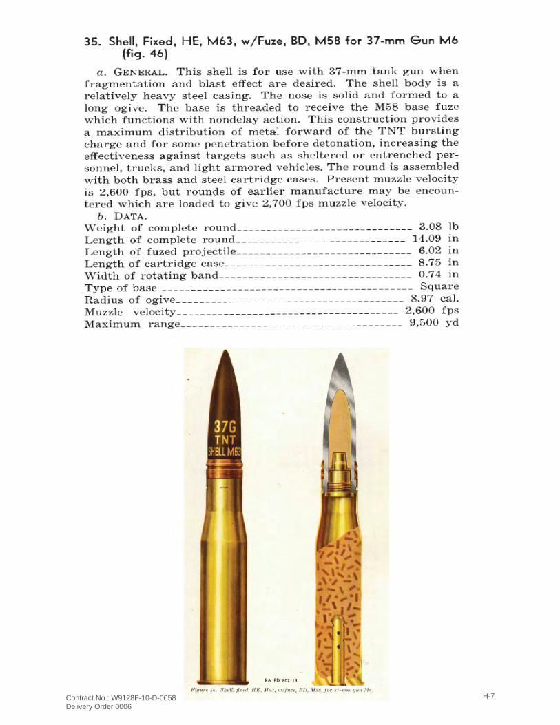
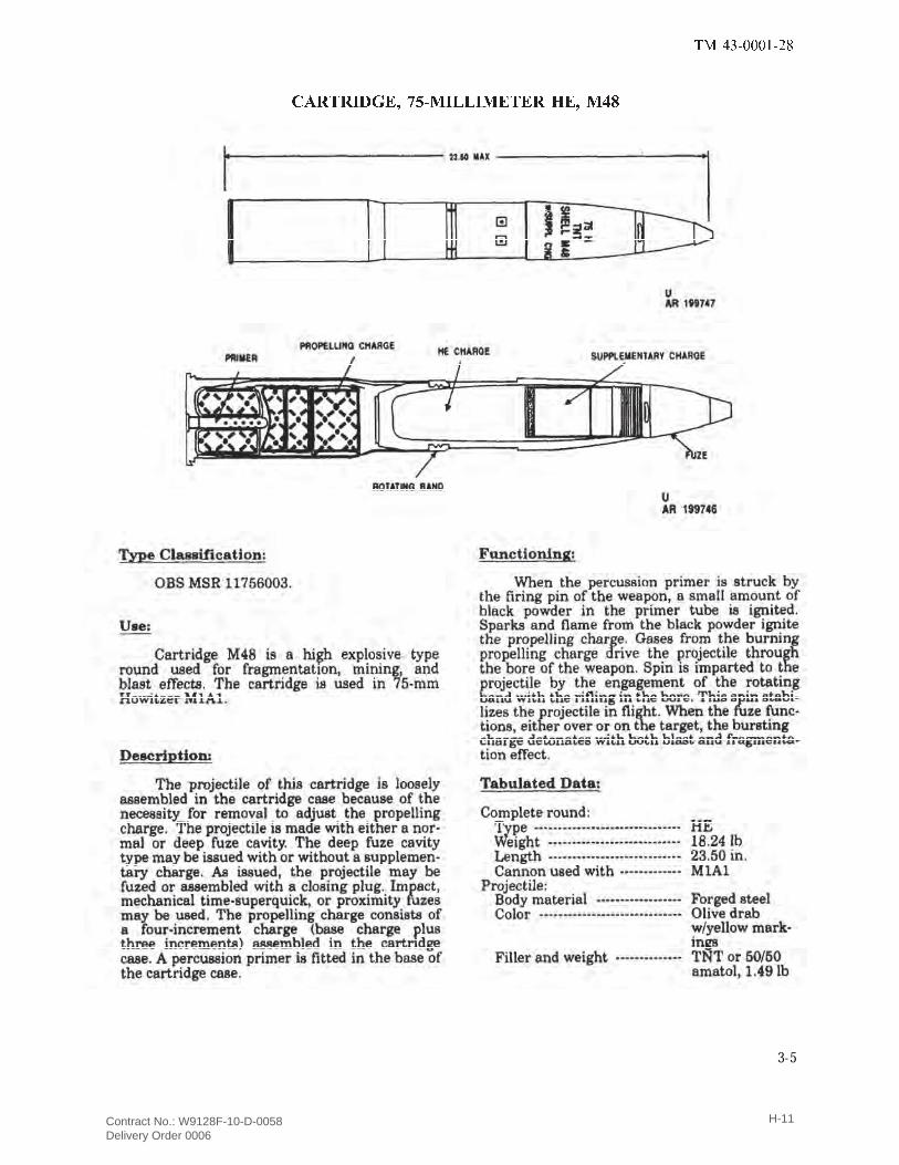
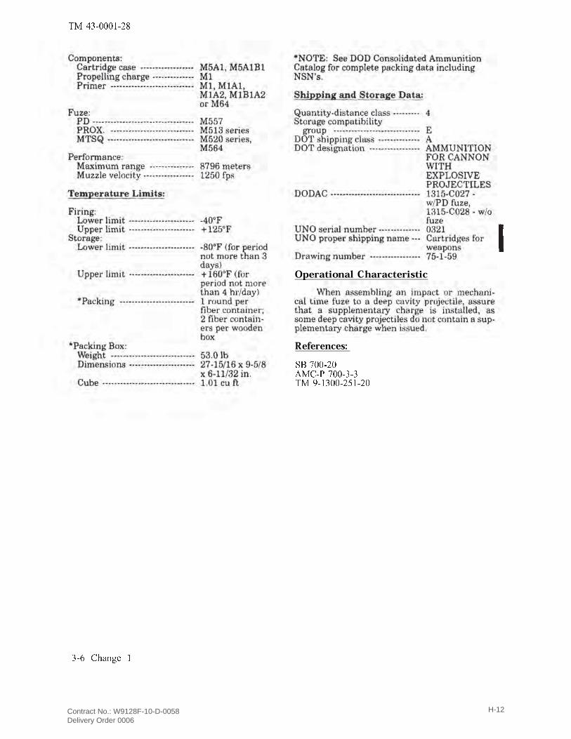
SHELL, CHEMICAL, M64. General. This round is a new type of chemical round, the projectile being equipped with a full length burster. It disperses the chemical agents more efficiently than does the older type chemical round (see SHELL, chemical, Mk. II, in section on 75-mm guns) since the entire projectile is split open. It may be expected that a chemical shell of this type will also be standardized for the 75-mm guns in the near future.
Projectile M64 figure 174. This projectile is similar to the H.E. Projectile M48 with the exception of an adapter for the burster casing in the nose, and the absence of a base plate. The burster casing is a press-fit in the adapter provided for it. The burster assembles within the burster casing. The standard fillers (chemical agents) for this shell are H, WP, and FS. The marking for these fillers will be similar to that for the same fillers in the SHELL, chemical, Mk. II. There are five weight zones in this projectile. The components associated with it in the complete round are: Fuze M57. Discussed in chapter on 75-mm gun ammunition. Burster M8. Burster Casing M6. Cartridge Casing M5A1 AND M5A1B1. Propelling Charge. FNH, 4 zone, base and increment. Primer M1B1A2. Discussed in chapter on 75-mm gun ammunition.
NOTE: This round is standard for manufacture and issue and is issued fuzed. It is a boresafe round.
TM 9-1904
Contract No.: W9128F-10-D-0058 Delivery Order 0006
H-9

TM 9-1904
Contract No.: W9128F-10-D-0058 Delivery Order 0006
H-10
� � � � � � � � � � � � � � � � � � � � � � � � � � � � � � � � � � � �
3-5
Contract No.: W9128F-10-D-0058 Delivery Order 0006
H-11
� � � � � � � � � ! "
Operational Characteristic
References:# $ % � � � ! �& � ' � ( % � � � � � �� � ) � � � � � ! * � ! �
+ , - . / 0 1 2 3 4Contract No.: W9128F-10-D-0058 Delivery Order 0006
H-12
Port Angeles Combat Range, WA | Remedial Investigation/Feasibility Study Final Report APPENDIX I DEMILITARIZATION DOCUMENTATION
APPENDIX I
Demilitarization Documentation

Port Angeles Combat Range, WA | Remedial Investigation/Feasibility Study Final Report APPENDIX I DEMILITARIZATION DOCUMENTATION
This page intentionally left blank.
Contract No.: W9128F-10-D-0058 Delivery Order 0006
I-1
Contract No.: W9128F-10-D-0058 Delivery Order 0006
I-2
Contract No.: W9128F-10-D-0058 Delivery Order 0006
I-3
Contract No.: W9128F-10-D-0058 Delivery Order 0006
I-4

Port Angeles Combat Range, WA | Remedial Investigation/Feasibility Study Final Report APPENDIX J SUMMARY OF LEAD IN SOILS – X-RAY FLUORESCENCE SCREENING DATA
APPENDIX J
Summary of Lead in Soils – X-ray Fluorescence Screening Data

Port Angeles Combat Range, WA | Remedial Investigation/Feasibility Study Final Report APPENDIX J SUMMARY OF LEAD IN SOILS – X-RAY FLUORESCENCE SCREENING DATA
This page intentionally left blank.
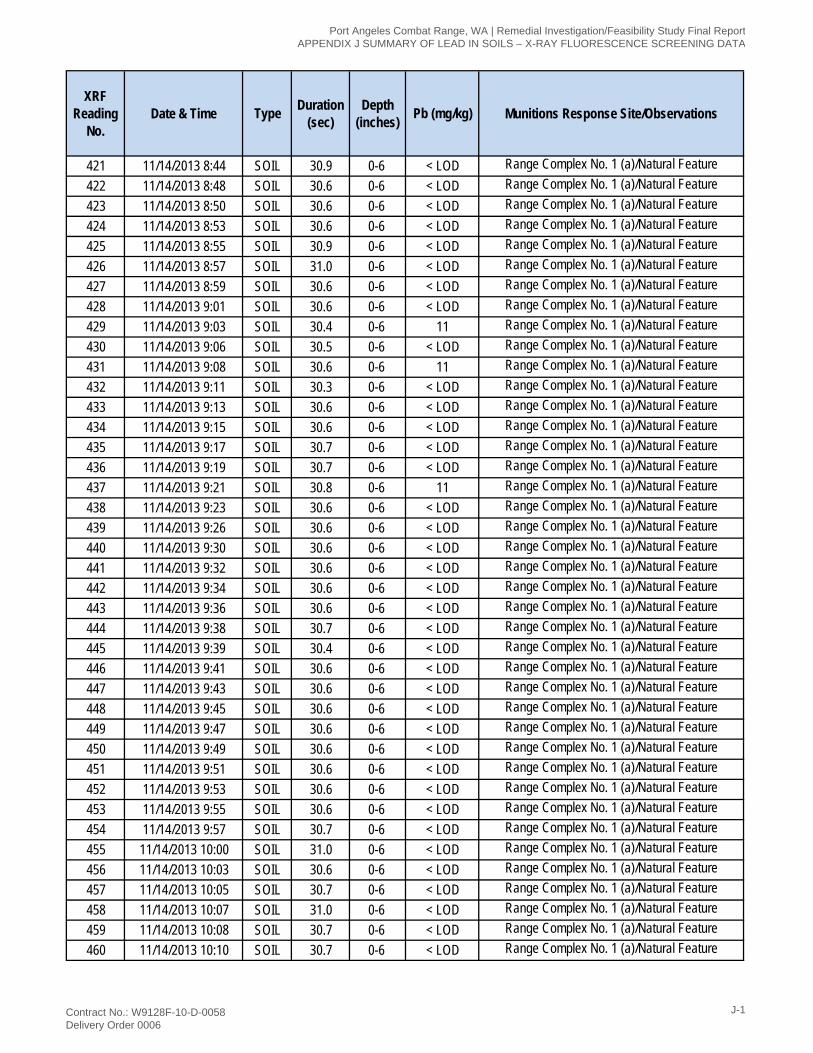
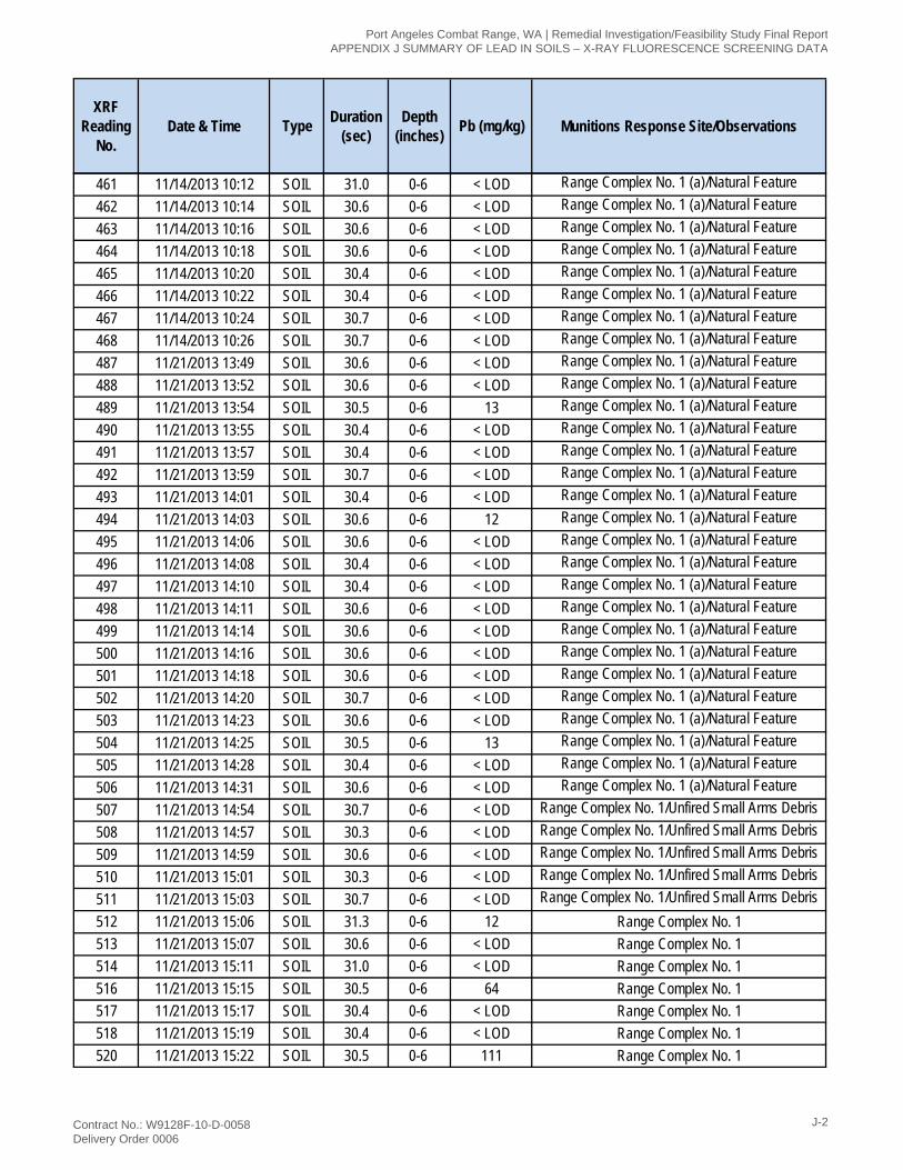
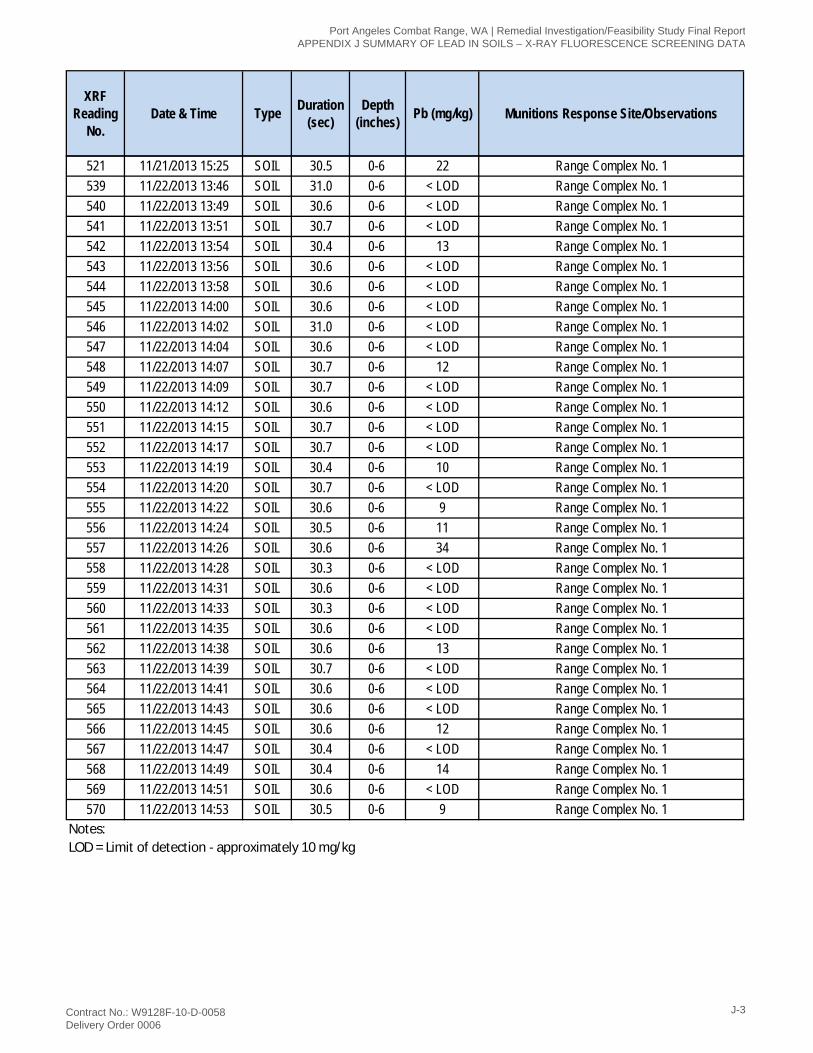
XRF Reading
No.Date & Time Type Duration
(sec)Depth
(inches) Pb (mg/kg) Munitions Response Site/Observations
421 11/14/2013 8:44 SOIL 30.9 0-6 < LOD Range Complex No. 1 (a)/Natural Feature422 11/14/2013 8:48 SOIL 30.6 0-6 < LOD Range Complex No. 1 (a)/Natural Feature423 11/14/2013 8:50 SOIL 30.6 0-6 < LOD Range Complex No. 1 (a)/Natural Feature424 11/14/2013 8:53 SOIL 30.6 0-6 < LOD Range Complex No. 1 (a)/Natural Feature425 11/14/2013 8:55 SOIL 30.9 0-6 < LOD Range Complex No. 1 (a)/Natural Feature426 11/14/2013 8:57 SOIL 31.0 0-6 < LOD Range Complex No. 1 (a)/Natural Feature427 11/14/2013 8:59 SOIL 30.6 0-6 < LOD Range Complex No. 1 (a)/Natural Feature428 11/14/2013 9:01 SOIL 30.6 0-6 < LOD Range Complex No. 1 (a)/Natural Feature429 11/14/2013 9:03 SOIL 30.4 0-6 11 Range Complex No. 1 (a)/Natural Feature430 11/14/2013 9:06 SOIL 30.5 0-6 < LOD Range Complex No. 1 (a)/Natural Feature431 11/14/2013 9:08 SOIL 30.6 0-6 11 Range Complex No. 1 (a)/Natural Feature432 11/14/2013 9:11 SOIL 30.3 0-6 < LOD Range Complex No. 1 (a)/Natural Feature433 11/14/2013 9:13 SOIL 30.6 0-6 < LOD Range Complex No. 1 (a)/Natural Feature434 11/14/2013 9:15 SOIL 30.6 0-6 < LOD Range Complex No. 1 (a)/Natural Feature435 11/14/2013 9:17 SOIL 30.7 0-6 < LOD Range Complex No. 1 (a)/Natural Feature436 11/14/2013 9:19 SOIL 30.7 0-6 < LOD Range Complex No. 1 (a)/Natural Feature437 11/14/2013 9:21 SOIL 30.8 0-6 11 Range Complex No. 1 (a)/Natural Feature438 11/14/2013 9:23 SOIL 30.6 0-6 < LOD Range Complex No. 1 (a)/Natural Feature439 11/14/2013 9:26 SOIL 30.6 0-6 < LOD Range Complex No. 1 (a)/Natural Feature440 11/14/2013 9:30 SOIL 30.6 0-6 < LOD Range Complex No. 1 (a)/Natural Feature441 11/14/2013 9:32 SOIL 30.6 0-6 < LOD Range Complex No. 1 (a)/Natural Feature442 11/14/2013 9:34 SOIL 30.6 0-6 < LOD Range Complex No. 1 (a)/Natural Feature443 11/14/2013 9:36 SOIL 30.6 0-6 < LOD Range Complex No. 1 (a)/Natural Feature444 11/14/2013 9:38 SOIL 30.7 0-6 < LOD Range Complex No. 1 (a)/Natural Feature445 11/14/2013 9:39 SOIL 30.4 0-6 < LOD Range Complex No. 1 (a)/Natural Feature446 11/14/2013 9:41 SOIL 30.6 0-6 < LOD Range Complex No. 1 (a)/Natural Feature447 11/14/2013 9:43 SOIL 30.6 0-6 < LOD Range Complex No. 1 (a)/Natural Feature448 11/14/2013 9:45 SOIL 30.6 0-6 < LOD Range Complex No. 1 (a)/Natural Feature449 11/14/2013 9:47 SOIL 30.6 0-6 < LOD Range Complex No. 1 (a)/Natural Feature450 11/14/2013 9:49 SOIL 30.6 0-6 < LOD Range Complex No. 1 (a)/Natural Feature451 11/14/2013 9:51 SOIL 30.6 0-6 < LOD Range Complex No. 1 (a)/Natural Feature452 11/14/2013 9:53 SOIL 30.6 0-6 < LOD Range Complex No. 1 (a)/Natural Feature453 11/14/2013 9:55 SOIL 30.6 0-6 < LOD Range Complex No. 1 (a)/Natural Feature454 11/14/2013 9:57 SOIL 30.7 0-6 < LOD Range Complex No. 1 (a)/Natural Feature455 11/14/2013 10:00 SOIL 31.0 0-6 < LOD Range Complex No. 1 (a)/Natural Feature456 11/14/2013 10:03 SOIL 30.6 0-6 < LOD Range Complex No. 1 (a)/Natural Feature457 11/14/2013 10:05 SOIL 30.7 0-6 < LOD Range Complex No. 1 (a)/Natural Feature458 11/14/2013 10:07 SOIL 31.0 0-6 < LOD Range Complex No. 1 (a)/Natural Feature459 11/14/2013 10:08 SOIL 30.7 0-6 < LOD Range Complex No. 1 (a)/Natural Feature460 11/14/2013 10:10 SOIL 30.7 0-6 < LOD Range Complex No. 1 (a)/Natural Feature
Port Angeles Combat Range, WA | Remedial Investigation/Feasibility Study Final Report APPENDIX J SUMMARY OF LEAD IN SOILS – X-RAY FLUORESCENCE SCREENING DATA
Contract No.: W9128F-10-D-0058 Delivery Order 0006
J-1
XRF Reading
No.Date & Time Type Duration
(sec)Depth
(inches) Pb (mg/kg) Munitions Response Site/Observations
461 11/14/2013 10:12 SOIL 31.0 0-6 < LOD Range Complex No. 1 (a)/Natural Feature462 11/14/2013 10:14 SOIL 30.6 0-6 < LOD Range Complex No. 1 (a)/Natural Feature463 11/14/2013 10:16 SOIL 30.6 0-6 < LOD Range Complex No. 1 (a)/Natural Feature464 11/14/2013 10:18 SOIL 30.6 0-6 < LOD Range Complex No. 1 (a)/Natural Feature465 11/14/2013 10:20 SOIL 30.4 0-6 < LOD Range Complex No. 1 (a)/Natural Feature466 11/14/2013 10:22 SOIL 30.4 0-6 < LOD Range Complex No. 1 (a)/Natural Feature467 11/14/2013 10:24 SOIL 30.7 0-6 < LOD Range Complex No. 1 (a)/Natural Feature468 11/14/2013 10:26 SOIL 30.7 0-6 < LOD Range Complex No. 1 (a)/Natural Feature487 11/21/2013 13:49 SOIL 30.6 0-6 < LOD Range Complex No. 1 (a)/Natural Feature488 11/21/2013 13:52 SOIL 30.6 0-6 < LOD Range Complex No. 1 (a)/Natural Feature489 11/21/2013 13:54 SOIL 30.5 0-6 13 Range Complex No. 1 (a)/Natural Feature490 11/21/2013 13:55 SOIL 30.4 0-6 < LOD Range Complex No. 1 (a)/Natural Feature491 11/21/2013 13:57 SOIL 30.4 0-6 < LOD Range Complex No. 1 (a)/Natural Feature492 11/21/2013 13:59 SOIL 30.7 0-6 < LOD Range Complex No. 1 (a)/Natural Feature493 11/21/2013 14:01 SOIL 30.4 0-6 < LOD Range Complex No. 1 (a)/Natural Feature494 11/21/2013 14:03 SOIL 30.6 0-6 12 Range Complex No. 1 (a)/Natural Feature495 11/21/2013 14:06 SOIL 30.6 0-6 < LOD Range Complex No. 1 (a)/Natural Feature496 11/21/2013 14:08 SOIL 30.4 0-6 < LOD Range Complex No. 1 (a)/Natural Feature497 11/21/2013 14:10 SOIL 30.4 0-6 < LOD Range Complex No. 1 (a)/Natural Feature498 11/21/2013 14:11 SOIL 30.6 0-6 < LOD Range Complex No. 1 (a)/Natural Feature499 11/21/2013 14:14 SOIL 30.6 0-6 < LOD Range Complex No. 1 (a)/Natural Feature500 11/21/2013 14:16 SOIL 30.6 0-6 < LOD Range Complex No. 1 (a)/Natural Feature501 11/21/2013 14:18 SOIL 30.6 0-6 < LOD Range Complex No. 1 (a)/Natural Feature502 11/21/2013 14:20 SOIL 30.7 0-6 < LOD Range Complex No. 1 (a)/Natural Feature503 11/21/2013 14:23 SOIL 30.6 0-6 < LOD Range Complex No. 1 (a)/Natural Feature504 11/21/2013 14:25 SOIL 30.5 0-6 13 Range Complex No. 1 (a)/Natural Feature505 11/21/2013 14:28 SOIL 30.4 0-6 < LOD Range Complex No. 1 (a)/Natural Feature506 11/21/2013 14:31 SOIL 30.6 0-6 < LOD Range Complex No. 1 (a)/Natural Feature507 11/21/2013 14:54 SOIL 30.7 0-6 < LOD Range Complex No. 1/Unfired Small Arms Debris508 11/21/2013 14:57 SOIL 30.3 0-6 < LOD Range Complex No. 1/Unfired Small Arms Debris509 11/21/2013 14:59 SOIL 30.6 0-6 < LOD Range Complex No. 1/Unfired Small Arms Debris510 11/21/2013 15:01 SOIL 30.3 0-6 < LOD Range Complex No. 1/Unfired Small Arms Debris511 11/21/2013 15:03 SOIL 30.7 0-6 < LOD Range Complex No. 1/Unfired Small Arms Debris512 11/21/2013 15:06 SOIL 31.3 0-6 12 Range Complex No. 1513 11/21/2013 15:07 SOIL 30.6 0-6 < LOD Range Complex No. 1514 11/21/2013 15:11 SOIL 31.0 0-6 < LOD Range Complex No. 1516 11/21/2013 15:15 SOIL 30.5 0-6 64 Range Complex No. 1517 11/21/2013 15:17 SOIL 30.4 0-6 < LOD Range Complex No. 1518 11/21/2013 15:19 SOIL 30.4 0-6 < LOD Range Complex No. 1520 11/21/2013 15:22 SOIL 30.5 0-6 111 Range Complex No. 1
Port Angeles Combat Range, WA | Remedial Investigation/Feasibility Study Final Report APPENDIX J SUMMARY OF LEAD IN SOILS – X-RAY FLUORESCENCE SCREENING DATA
Contract No.: W9128F-10-D-0058 Delivery Order 0006
J-2
XRF Reading
No.Date & Time Type Duration
(sec)Depth
(inches) Pb (mg/kg) Munitions Response Site/Observations
521 11/21/2013 15:25 SOIL 30.5 0-6 22 Range Complex No. 1539 11/22/2013 13:46 SOIL 31.0 0-6 < LOD Range Complex No. 1540 11/22/2013 13:49 SOIL 30.6 0-6 < LOD Range Complex No. 1541 11/22/2013 13:51 SOIL 30.7 0-6 < LOD Range Complex No. 1542 11/22/2013 13:54 SOIL 30.4 0-6 13 Range Complex No. 1543 11/22/2013 13:56 SOIL 30.6 0-6 < LOD Range Complex No. 1544 11/22/2013 13:58 SOIL 30.6 0-6 < LOD Range Complex No. 1545 11/22/2013 14:00 SOIL 30.6 0-6 < LOD Range Complex No. 1546 11/22/2013 14:02 SOIL 31.0 0-6 < LOD Range Complex No. 1547 11/22/2013 14:04 SOIL 30.6 0-6 < LOD Range Complex No. 1548 11/22/2013 14:07 SOIL 30.7 0-6 12 Range Complex No. 1549 11/22/2013 14:09 SOIL 30.7 0-6 < LOD Range Complex No. 1550 11/22/2013 14:12 SOIL 30.6 0-6 < LOD Range Complex No. 1551 11/22/2013 14:15 SOIL 30.7 0-6 < LOD Range Complex No. 1552 11/22/2013 14:17 SOIL 30.7 0-6 < LOD Range Complex No. 1553 11/22/2013 14:19 SOIL 30.4 0-6 10 Range Complex No. 1554 11/22/2013 14:20 SOIL 30.7 0-6 < LOD Range Complex No. 1555 11/22/2013 14:22 SOIL 30.6 0-6 9 Range Complex No. 1556 11/22/2013 14:24 SOIL 30.5 0-6 11 Range Complex No. 1557 11/22/2013 14:26 SOIL 30.6 0-6 34 Range Complex No. 1558 11/22/2013 14:28 SOIL 30.3 0-6 < LOD Range Complex No. 1559 11/22/2013 14:31 SOIL 30.6 0-6 < LOD Range Complex No. 1560 11/22/2013 14:33 SOIL 30.3 0-6 < LOD Range Complex No. 1561 11/22/2013 14:35 SOIL 30.6 0-6 < LOD Range Complex No. 1562 11/22/2013 14:38 SOIL 30.6 0-6 13 Range Complex No. 1563 11/22/2013 14:39 SOIL 30.7 0-6 < LOD Range Complex No. 1564 11/22/2013 14:41 SOIL 30.6 0-6 < LOD Range Complex No. 1565 11/22/2013 14:43 SOIL 30.6 0-6 < LOD Range Complex No. 1566 11/22/2013 14:45 SOIL 30.6 0-6 12 Range Complex No. 1567 11/22/2013 14:47 SOIL 30.4 0-6 < LOD Range Complex No. 1568 11/22/2013 14:49 SOIL 30.4 0-6 14 Range Complex No. 1569 11/22/2013 14:51 SOIL 30.6 0-6 < LOD Range Complex No. 1570 11/22/2013 14:53 SOIL 30.5 0-6 9 Range Complex No. 1
Notes: LOD = Limit of detection - approximately 10 mg/kg
Port Angeles Combat Range, WA | Remedial Investigation/Feasibility Study Final Report APPENDIX J SUMMARY OF LEAD IN SOILS – X-RAY FLUORESCENCE SCREENING DATA
Contract No.: W9128F-10-D-0058 Delivery Order 0006
J-3

This page intentionally left blank.
Port Angeles Combat Range, WA | Remedial Investigation/Feasibility Study Final Report APPENDIX J SUMMARY OF LEAD IN SOILS – X-RAY FLUORESCENCE SCREENING DATA
Contract No.: W9128F-10-D-0058 Delivery Order 0006
J-4