APPENDIX 'E' Geotechnical Report - City of PeterboroughAssets/Engineering/Documents/... · The...
19
City of Peterborough Lansdowne Street West ENVIRONMENTAL STUDY REPORT Our File: 6552 ADDENDUM March 2008 APPENDIX 'E' Geotechnical Report
Transcript of APPENDIX 'E' Geotechnical Report - City of PeterboroughAssets/Engineering/Documents/... · The...
City of Peterborough Lansdowne Street West ENVIRONMENTAL STUDY REPORT Our File: 6552 ADDENDUM
March 2008
APPENDIX 'E'
Geotechnical Report
•
347 Pido Road, Unit 29Peterborough, Ontario K9J 6X7
tel: (705) 749-3317fax: (705) 749-9248
email: [email protected]
February 9, 2007Utility Services DepartmentEngineering and Construction DivisionCity of Peterborough500 George StreetPeterborough, Ontario K9H 3R9
Attention: Mr. Bryan Robinson, P.Eng.
re: Geotechnical Investigation Letter ReportLansdowne Street WestCity of Peterborough, OntarioGeo-Logic Inc. Project No. 06-G-180-3 (G020 365 A3)
Dear Mr. Robinson:
1.0 INTRODUCTION
The following letter report describes the results of a geotechnical investigation performed for theproposed reconstruction of Lansdowne Street West from Spillsbury Drive west to the City Limit,in the City of Peterborough, Ontario. It is understood that this project shall include installationof underground servicing, as well as reconstruction of this portion of roadway. Geo-Logic Inc.(Geo-Logic) was retained by the City of Peterborough (the City) to conduct this investigation asoutlined in Geo-Logic Inco's proposal dated October 25,2006.
It is noted that the City outlined the number, location, and depth of boreholes to be drilled forthis project. This information was provided in the City's request for proposal (RFP), CityDocument No. P-31-06, and has been used to generate the attached Borehole Location Plan(Plate 1). In addition, the City has provided the UTM coordinates and elevation values that areshown on the Borehole Logs (Plate 2).
soil / environmental • materials testing • hydrogeology

Geotechnical Investigation Letter ReportLansdowne Street WestCity of Peterborough, Ontario
Geo-Logic Inc.
Project No. 06-G-180-3 (G020 365 A3)
2.0 PURPOSE AND SCOPE
The purpose of this geotechnical investigation is to explore the subsurface conditions at the
borehole locations, and provide geotechnical engineering conclusions and recommendations
relevant to excavation, dewatering, pipe installation, backfill, and pavement design.
Note that this work, and the contents of this report, must in no way be construed as an
environmental opinion of this site. Should such an opinion be desired, it is recommended that an
Environmental Site Assessment (ESA) be conducted.
The following scope of work was performed as part of this investigation.
1. Underground services were cleared, and the boreholes were located in reference to sitefeatures, approximately at the locations requested by the City. (Note that exact locations areprovided in the form of UTM coordinates included on the attached Borehole Logs. Thesecoordinates were provided by the City.)
2. The subsurface conditions were explored by drilling, sampling and logging eight (8)boreholes (as requested) to depths ranging between 4.5 and 6.1 metres below existing grade(mbeg).
3. Geotechnical analyses of materials encountered were performed by means of physicallaboratory testing to obtain relevant soil physical properties, including grain size distributionand moisture content tests.
4. Geotechnical engineering analysis of acquired field data, and preparation of a letter reportoutlining our findings, conclusions, and geotechnical engineering recommendations relevantto this project.
3.0 FIELDWORK AND LABORATORY ANALYSIS
A field investigation was conducted under the supervision of Geo-Logic staff on November 22and 23, 2006. The work consisted of subsurface exploration by means of drilling, sampling andlogging a total of eight (8) exploratory boreholes. The approximate location of each borehole is
illustrated on the attached Borehole Location Plan (Plate 1), while the exact coordinates of eachborehole (as obtained from the City) are provided on the Borehole Logs (Plate 2).
2
Geotechnical Investigation Letter ReportLansdowne Street WestCity of Peterborough, Ontario
Geo-Logic Inc.
Project No. 06-G-180-3 (G020 365 A3)
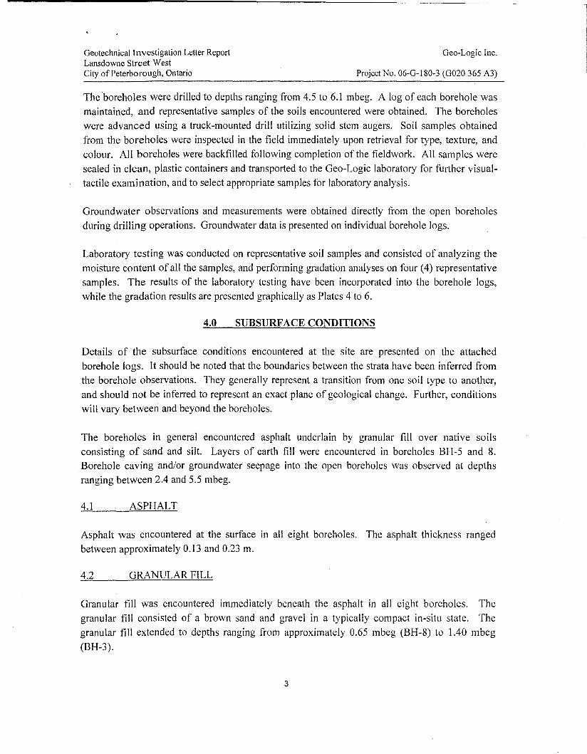
The boreholes were drilled to depths ranging from 4.5 to 6.1 mbeg. A log of each borehole was
maintained, and representative samples of the soils encountered were obtained. The boreholes
were advanced using a truck-mounted drill utilizing solid stem augers. Soil samples obtainedfrom the boreholes were inspected in the field immediately upon retrieval for type, texture, and
colour. All boreholes were backfilled following completion of the fieldwork. All samples were
sealed in clean, plastic containers and transported to the Geo-Logic laboratory for further visualtactile examination, and to select appropriate samples for laboratory analysis.
Groundwater observations and measurements were obtained directly from the open boreholes
during drilling operations. Groundwater data is presented on individual borehole logs.
Laboratory testing was conducted on representative soil samples and consisted of analyzing the
moisture content of all the samples, and performing gradation analyses on four (4) representativesamples. The results of the laboratory testing have been incorporated into the borehole logs,while the gradation results are presented graphically as Plates 4 to 6.
4.0 SUBSURFACE CONDITIONS
Details of the subsurface conditions encountered at the site are presented on the attached
borehole logs. It should be noted that the boundaries between the strata have been inferred fromthe borehole observations. They generally represent a transition from one soil type to another,
and should not be inferred to represent an exact plane of geological change. Further, conditions
will vary between and beyond the boreholes.
The boreholes in general encountered asphalt underlain by granular fill over native soils
consisting of sand and silt. Layers of earth fill were encountered in boreholes BH-5 and 8.Borehole caving and/or groundwater seepage into the open boreholes was observed at depths
ranging between 2.4 and 5.5 mbeg.
4.1 ASPHALT
Asphalt was encountered at the surface in all eight boreholes. The asphalt thickness ranged
between approximately 0.13 and 0.23 m.
4.2 GRANULAR FILL
Granular fill was encountered immediately beneath the asphalt in all eight boreholes. The
granular fill consisted of a brown sand and gravel in a typically compact in-situ state. The
granular fill extended to depths ranging from approximately 0.65 mbeg (BH-8) to 1.40 mbeg
(BH-3).
3

Geotechnical Investigation Letter ReportLansdowne Street WestCity of Peterborough, Ontario
Geo-Logic Inc.
Project No. 06-G-180-3 (G020 365 A3)
Moisture content tests performed on the granular fill yielded values ranging from about 1 to 10%moisture by weight. Grain size distribution analyses were conducted on two representative
samples of the granular fill, and the results are compared to Ontario Provincial StandardSpecifications (OPSS) for Granular "B" Type I material on Plate 4. The results suggest that the
samples tested contain an excess of fine grained particles (less than 0.075mm).
4.3 EARTH FILL
A layer of earth fill material was encountered immediately beneath the granular fill in boreholes
BH-5 and 8. This layer extended to depths of approximately 2.44 (BH-5) and 1.30 mbeg (BH-8).The earth fill was brown, and consisted of silty sand with gravel, in a loose to compact in-situ
state. Moisture content tests performed on samples of the earth fill yielded values ranging fromapproximately II to 15 % moisture by weight.
Based on laboratory results and visual-tactile examination of this soil, the earth fill is expected to
possess a low to moderate susceptibility to frost action, and appears to be above its optimal
moisture content for compaction purposes.
4.4 SAND / SILTY SAND
A layer of sand or silty sand was encountered in boreholes BH-2, 3,4, 6, 7, and 8. These soils
were first observed at depths ranging between about 0.86 to 1.40 mbeg, and extended to depths
ranging from 1.5 mbeg to the full depth of investigation. The sand and silty sand soils weregenerally brown to reddish brown in colour, with occasional gravel and cobbles observed, and a
typically fine- to medium-grained texture. These soils were observed to be in a typically
compact in-situ state.
Moisture content tests performed on samples of the sand and silty sand yielded values rangingfrom about 2 to 14 % moisture by weight. Grain size distribution analyses conducted on samples
of the sand and silty sand suggests the following compositional ranges: 3 to 5 % gravel, 56 to84% sand, and 11 to 41 % silt and clay-sized particles. Hydrometer analyses performed on these
samples indicates they contain approximately 7 to 26 % particles between 5 and 75 J.!m in size.
Based on the results of the laboratory tests, and visual-tactile examination of the samples
obtained, these soils are expected to exhibit a low frost susceptibility.
4
Geotechnical Investigation Letter ReportLansdowne Street WestCity of Peterborough, Ontario
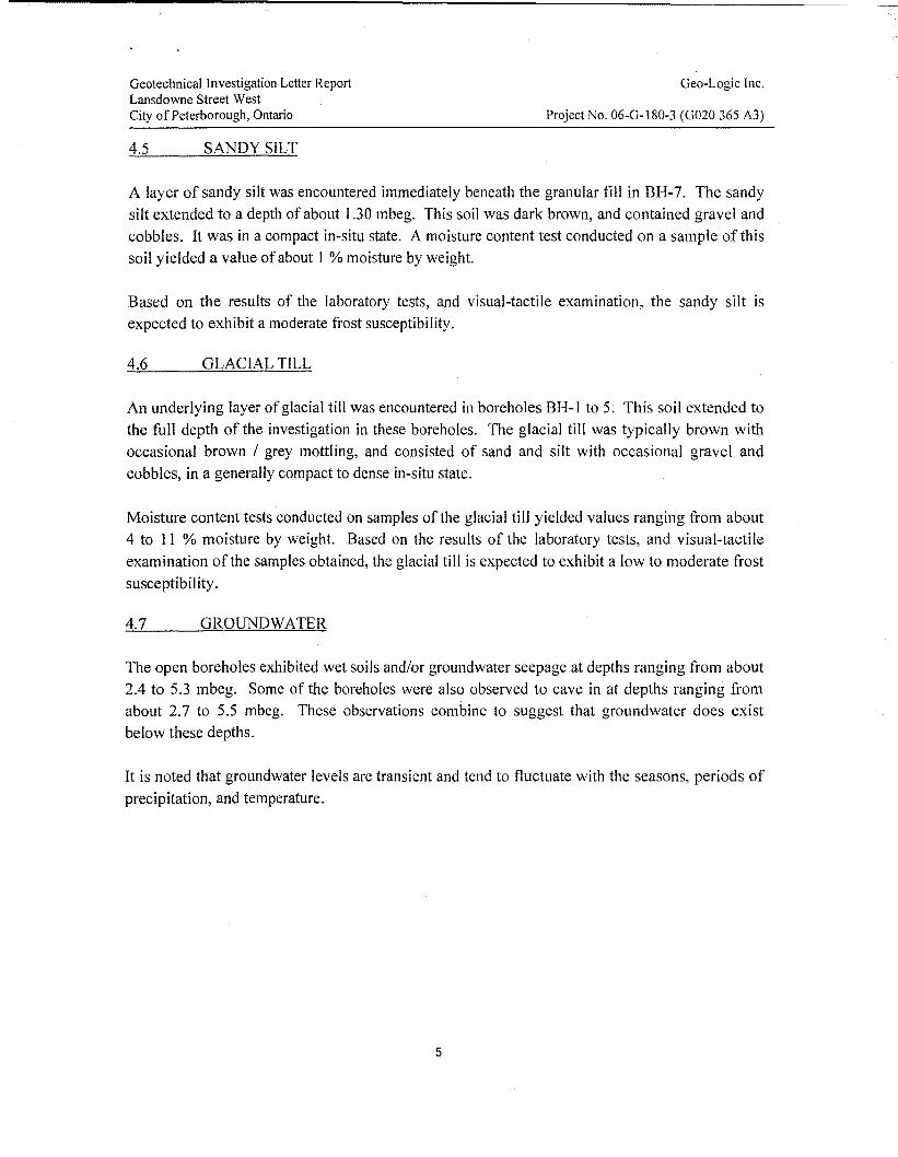
4.5 SANDY SILT
Geo-Logic Inc.
Project No. 06-G-180-3 (G020 365 A3)
A layer of sandy silt was encountered immediately beneath the granular fill in BH-7. The sandy
silt extended to a depth of about 1.30 mbeg. This soil was dark brown, and contained gravel and
cobbles. It was in a compact in-situ state. A moisture content test conducted on a sample of this
soil yielded a value of about 1 % moisture by weight.
Based on the results of the laboratory tests, and visual-tactile examination, the sandy silt is
expected to exhibit a moderate frost susceptibility.
4.6 GLACIAL TILL
An underlying layer of glacial till was encountered in boreholes BH-1 to 5. This soil extended to
the full depth of the investigation in these boreholes. The glacial till was typically brown with
occasional brown / grey mottling, and consisted of sand and silt with occasional gravel and
cobbles, in a generally compact to dense in-situ state.
Moisture content tests conducted on samples of the glacial till yielded values ranging from about
4 to 11 % moisture by weight. Based on the results of the laboratory tests, and visual-tactile
examination of the samples obtained, the glacial till is expected to exhibit a low to moderate frost
susceptibility.
4.7 GROUNDWATER
The open boreholes exhibited wet soils and/or groundwater seepage at depths ranging from about
2.4 to 5.3 mbeg. Some of the boreholes were also observed to cave in at depths ranging from
about 2.7 to 5.5 mbeg. These observations combine to suggest that groundwater does exist
below these depths.
It is noted that groundwater levels are transient and tend to fluctuate with the seasons, periods of
precipitation, and temperature.
5

Geotechnical Investigation Letter ReportLansdowne Street WestCity of Peterborough, Ontario
Geo-Logic Inc.
Project No. 06-G-180-3 (G020 365 A3)
5.0 CONCLUSIONS AND RECOMMENDATIONS
5.1 GENERAL
Supporting data upon which our recommendations are based have been presented in the
foregoing sections of this report. The following recommendations are governed by the physical
properties of the subsurface materials that were encountered at the boreholes, and assumes thatthey are representative of the overall site conditions. It should be noted that these conclusions
and recommendations are intended for use by the designers only. Contractors bidding on orundertaking any work at the site should examine the factual results of the investigation, satisfy
themselves as to the adequacy of the information for construction, and make their own
interpretation of this factual data as it affects their proposed construction techniques, equipmentcapabilities, costs, sequencing, and the like. Comments, techniques, or recommendations
pertaining to construction should not be construed as instructions to the contractor.
Details regarding our conclusions and recommendations are outlined in the following sections.
5.2 SITE PREPARATION, EXCAVATION, AND DEWATERING
Excavations should be carried out to conform to the manner specified in Ontario Regulation
213/91 and the Occupational Health and Safety Act and Regulations for Construction Projects
(OHSA). All excavations above the water table not exceeding 1.2 m in depth may beconstructed with unsupported slopes. The soils encountered during this investigation are classedby OHSA as Type 3. As such, unsupported walls of excavations in this soil must maintain a
gradient of 1 horizontal to I vertical (lH: 1V) or flatter.
Based on groundwater measurements, it is anticipated that groundwater seepage into open
excavations deeper than about 2.4 mbeg may be encountered. It is expected that pumping fromcollection sumps to an acceptable outlet will control this groundwater infiltration. Should anyexcavations require more intensive dewatering / groundwater control, the use of well points,
filtered sumps, or other suitable method of dewatering and/or sheet piling is recommended.
6

Geotechnical Investigation Letter ReportLansdowne Street WestCity of Peterborough, Ontario
5.3 BEDDING
Geo-Logic Inc.
Project No. 06-G-180-3 (G02D 365 A3)
The materials encountered during this investigation at anticipated service invert elevations
consists of native silt and sand soils. As such, a normal compacted Class "B" bedding is
recommended for all underground services, as per Class B1 detail from City of PeterboroughUtility Services Department Pipe Bedding Detail CPD410.01. Class "B" bedding 'is Granular"A", or 19 mm crusher run limestone, as per OPSS. The minimum recommended bedding
thickness for the underground services is 150 mm. All bedding should be cornpactedto 100 %of its Standard Proctor Maximum Dry Density (SPMDD).
5.4 BACKFILL
It is recommended that cover backfilling of underground services be accomplished using
Granular "A", sand, or other suitable material as allowed by the City's standards, to a minimum
of300 mm above the pipe, as per Class Bl ofCPD410.01. Compaction of this material should
be 100 % SPMDD.
Suitable excavated soil can be reused as trench backfill provided the soil is workable and at amoisture content that will permit adequate compaction. The only soils that may be considered as
reusable for backfill would be the glacial till. However, final review and approval to reuse this
soil must be made during construction. Saturated silts, organics, and wet clay (if encountered)should not be reused. Compaction of any native soil in service trenches is recommended to be a
minimum of 98 % of its SPMDD.
5.5 ROADWAY RECONSTRUCTION
Based on the results of this investigation, we would recommend the following options for
reconstruction ofthis portion of Lansdowne Street West:
• restoration; or• reconstruction.
The following sections outline the recommendations specific to each of the options listed above.
7

Geotechnical Investigation Letter ReportLansdowne Street WestCity of Peterborough, Ontario
Restoration
Geo-Logic Inc.
Project No. 06-G-180-3 (G020 365 A3)
For restoration of any road cuts it is recommended that the pavement and granular base
structures match the existing conditions, or comply with the City's design requirements.
Reconstruction
Based on the results of this investigation, we recommend the following procedures be
implemented to prepare this portion of Lansdowne Street West for reconstruction:
1. Remove any free organic topsoil and organic-bearing materials, unsuitable fill and earth fill,
frozen earth, and boulders larger than 150 mm in diameter encountered at subgrade elevationfor the full width ofconstruction.
2. Proof roll the subgrade for the purpose of detecting possible zones of overly wet or soft
subgrade. Any deleterious areas thus delineated should be replaced with acceptable earth fillor granular material compacted to a minimum of95 % of its SPMDD.
3. Contour the subgrade surface to prevent ponding of water during the construction and to
promote rapid drainage of the sub-base and base course materials.
4. To maximize drainage potential, 150 mm diameter perforated pipe subdrains should be
installed below any curb lines. The pipe should be encased in filter fabric and surrounded byclear stone aggregate. It is recommended that the subdrains discharge to a suitable, frost-freeoutlet.
5. Construct transitions between varying depths of granular base materials at a rate of 1:25minimum.
The subgrade materials encountered in these areas consisted of soils generally possessing a lowto potentially moderate frost susceptibility. In this regard, the following minimum flexible
pavement structure is recommended for the construction of the new roadway areas.
Table 1: Pavement Structure
Profile MaterialMinimum Thickness In Confonnance with
(mm) OPSS Fonn
Asphalt Surface H.L. 1 40 1150
Asphalt BaseH.L. 8
401150
(two lifts) 50
Granular Base Granular "A" 150 1010
Granular Subbase Granular "B" Type 1 (1) 450 1010(1) Modified III accordance with City of Peterborough specificatIOns
8

Geotechnical Investigation Letter ReportLansdowne Street WestCity of Peterborough, Ontario
Geo-Logic Inc.
Project No. 06-G-180-3 (G020 365 A3)
The following steps are recommended for optimum construction of these planned paved areas:
1. The Granular "A" and "B" courses should be compacted to a minimum 100 % of theirrespective SPMDD's.
2. All asphaltic concrete courses should be placed, spread and compacted conforming to OPSSForm 310 or equivalent. All asphaltic concrete should be compacted to a minimum of 97 %of their respective laboratory Marshall densities.
3. Adequate drainage should be provided to ensure satisfactory pavement performance.
It is recommended that all fill material be placed in uniform lifts not exceeding 200 millimetersin thickness before compaction. It is suggested that all granular material used as fill should havean in-situ moisture content within 2 % of their optimum moisture content. All granular materialsshould be compacted to 100 % SPMDD. Granular materials should consist of Granular "A" and"B" conforming to the requirements of OPSS Form 1010 or equivalent.
It should he noted that the above recommended pavement structures are for the end use ofthe project. During construction of the project the recommended granular depths may notbe sufficient to support loadings encountered.
5.7 TEST PITS DURING TENDERING
Due to the limitation of this report (see Section 6.0 "Statement of Limitations"), it isrecommended that test pits be dug at representative locations of this site during the tenderingphase, with mandatory attendance of interested contractors so that they can make their ownassessment regarding construction requirements. It is recommended that individual contractorsassess appiOpriate dewatering needs and ifrequired obtain the necessary permits for required.
9

Geoteclmical Investigation Letter ReportLansdowne Street WestCity of Peterborough, Ontario
Geo-Logic Inc.
Project No. 06-G-180-3 (G020 365 A3)
6.0 STATEMENT OF LIMITATIONS
The attached Statement of Limitations is an integral part of this report. We trust that the contentsof this letter meet with your immediate requirements. Should you have any questions orconcerns regarding any aspect of this report, or should you require any further assistance, please
do not hesitate to contact our office.
Gamet B , .Eng.
Project Engineer
V,{r;;:;\~LlVJv'-Nyle~n, P.Eng.Senior Engineer
19b
Encls: Borehole Location Plan (plate I)Borehole Logs (Plates 2 and 3)Laboratory Data (Plates 4 to 6)
Dis!: Bound reports (3 copies) hand-deliveredDigital version emailed([email protected])
10

Geotechnical Investigation Letter ReportLansdowne Street WestCity of Peterborough, Ontario
Oeo-Logic Inc.
Project No. 06-G-180-3 (G020 365 A3)
STATEMENT OF LIMITATIONS
The report is intended for the guidance of the designers. From a construction standpoint,contractors must make their own assessments of the groundwater and soil conditions at the siteand how these will affect their proposed construction methods, techniques and schedules.
The conclusions and recommendations in this report are based on information determined at the
borehole locations and on geological data of a general nature, which may be available for thearea investigated. Soil and groundwater conditions between and beyond the boreholes may
differ from those encountered at the borehole locations and conditions may become apparent
during construction, which could not be detected or anticipated at the time of the investigation.
We recommend that we be retained to ensure that all necessary subgrade preparationrequirements are met and to confirm that the soil conditions do not deviate materiaIIy from those
encountered at the borehole locations. In cases where this recommendation is not foIIowed, the
company's responsibility is limited to interpreting accurately the information encountered at the
boreholes.
This report is applicable only to the project described in the introduction, constructed
substantiaIIy in accordance with any details of alignment and elevations that may be quoted in
the text. This report has been prepared for the sole use of the City of Peterborough. Any usewhich a third party makes of this report, or any reliance on or decisions to be made based on it,
are the responsibility of such third parties. Oeo-Logic Inc accepts no responsibility for damages,
if any, suffered by any third party as a result of decisions made or actions based on this rep0l1.
11

Geotechnical Investigation Letter ReportLansdowne Street WestCity of Peterborough, Ontario
ENCLOSURES
12
Geo-Logic Inc.
Project No. 06-G-180-3 (G020 365 A3)

_. - ._-------- -------_._---_._------------_._~-------
.. j--)- BH1 <' ) \ I \ i "J " L \ (4.5m) " _/ \. I "',. BH2
.. ~ rlOWN-E-tf IN - t - - - 1 - - 1 - - - '1 ,,- - "1- - - 1- -l;.N~-DO;;\'~~--,.. _.~ - t ..:- - - t -"" - t - .;. - t - - ... i - - - i j4~ -t - ,---') ----'/" -----'\ --r --------"----r - -,- - - - - - -- - -::- - - - - - - - - - - -- - - - -....- - - , ' - - - -~- - - -.... " •• J 11'1 ( ~ \ \ .J Ii / <~ ?r- _
l
:. ~ ,,/r----.-..-..-.-____...... I. 'lo.jh _/ _: _............. ~. I;/ /'.
! I ' ~! I I .'.
6\; ! r-·---·-----·-'........... .._: = 0 ~',' " /'
I~J J 1--\-\ ....\. II \ ---- I --_...... ----/ \. L-, i '" r-J \ n.. i; :',,--- __. L-_
r--r~____ l ... l....",(
EJ.=..
fl47
tf?m.
,..,OIftoWllDNl.
o
GlrmJ
.:::--- STEWARTCROFT CRES ../
f'\ I1'iif"71' ,
I~
""
oo
11M
Jl_iII;
!
-~~--- L]·1,.
,
\ _ ~ h,,~il I~ II . _.._.... Iv· ........:..=:.J - ,.-_._1 BOREHOLE LOCATION__ ".. LANSDOWNE ST.W. N.T.s,
• BHB ---------- !- - - -1- - - -1-1 ~-ti4bawtitsT-..d· - 1 i- - - - +- - - ·r·:~~ - -1- - -1' - - - -~NE ST1V' cb .. BENCHMARKS:__________ '1. .1' ~ ~__. MONt 9920000107 MON. 1920000108
'Ii - - ...... - - - N-4l105385.173 N-4t05717A70- - - ... 1-709811,216 1-7IlI734.162
)L · ~~t.=-::STSIDE ~='~TSlOE~ , ,~ COfMlIIS ....~H) ml'lfMllMlmA1I MMltCffTIIflOtc. "tUMCltI:JMl8l1tJ ft."'KlU:MIIL1O \ BREALEY OR. ACROSS BREAlEY DR. JUST/'/ j I ~. _.. FROM FORSTER AVE. SOl1TH OF LANSDOWNE
Ii 1lf7l I [7h n ST.I( I~ ..~ [;] == ~ ~ ~ ~;ND=~~UIl'.i:J,oIBon>hok> DRAv.1Nl>I4I1-.K'
BOREHOLE LOCATION PLAN Date:
Scale:
February, 2007
NTS
GEOTECHNICAL INVESTIGATION REPORTLANSDOHWE STREET WEST
CITY OFPETERBOROUGH, ONTARIO
Project No.:
Plate No.:
06-G-180-3 (G020 365 A3)347 PIDO ROAD, UNIT 29
PETERBOROUGH, ON K9J 6X7(705) 749-3311 FAX (705) 149-9248 EMAIl.:[email protected]

BOREHOLE LOGSLANSDOWNE STREET WEST: SPILLSBURY DRIVE TO CITY LIMIT
CITY OF PETERBOROUGH, ONTARIOGEO-LOGIC INC. PROJECT NO. 06-G-180-3 (G020 365 A3)
Page 1 of 2
BH-2
BH-3
BH-4
4905762.07 709531.510 264.546
4905824.83 709693.630 259.347
4905800.88 709738.057 258.645
0.000.150.350.812.003.00
0.000.150.350.902.00
0.000.230.531.401.502.153.00
0.000.200.861.733.66
0.150.350.902.004.50
Notes:
0.230.531.401.502.153.004.50
Notes:
0.200.861.733.665.50
Notes:
Notes
ASPHALTGRANULAR FILL - brown, crushed Gravel and Sand
- Sand with GravelGLACIAL TILL - brown Sand and Silt, compact
- moist to very moist, loose- dense
Borehole remained open and dry
ASPHALTGRANULAR FILL - brown, crushed Gravel and Sand
- Sand with GravelSILTY SAND - reddish brown Silty Sand with Gravel and CobblesGLACIAL TILL - light brown Sand and Silt with occasional Cobbles, moist,Borehole remained open and dry
ASPHALTGRANULAR FILL - brown, crushed Gravel and Sand
- Sand with GravelSILTY SAND - dark brown Silty Sand with ClayGLACIAL TILL - brown Sand and Silt, moist, compact
- very moist-wet
Borehole remained open and dry
ASPHALTGRANULAR FILLSILTY SAND - brown Silty Sand with Gravel, damp, loose to compact (poss.GLACIAL TILL - brown Sand with trace Sift and Gravel, texture coarsening w
- with GravelBorehole caved in at about 4.0 mbeg, water seepage at about 5.3 mbeg
AS-1AS-2AS-3AS-4
AS-1
AS-2
AS-1AS-2AS-3
AS-4
AS-1AS-2
AS-3
0.93.34.07.2
10.0
3.7
1.11.6
11.2
9.0
3.310.8
9.9
Plate 2

Page 2 of 2BOREHOLE LOGS
LANSDOWNE STREET WEST: SPILLSBURY DRIVE TO CITY LIMITCITY OF PETERBOROUGH, ONTARIO
GEO·LOGIC INC. PROJECT NO. 06·G·180·3 (G020 365 A3)
BH-5 258.664 0.000.200.361.172.443.00
Notes
ASPHALTGRANULAR FILL - crushed Gravel and Sand
- Sand with GravelEARTH FILL - brown Silty Sand, damp, loose to compactGLACIAL TILL - grey I brown mottled Silty Sand, moist
-wetBorehole caved in at about 3.0 mbeg, water seepage at about 3.0 mbeg
AS-1
AS-2AS-3
3.2
10.810.9
BH-6
BH-7
4905855.35 709785.140 260.892 0.00 0.15 ASPHALT0.15 0.30 GRANULAR FILL - brown, crushed Gravel and Sand AS-1 1.20.30 1.20 - Sand with Gravel AS-2 1.51.20 3.65 SAND - light brown Sand, fine-grained, moist, compact AS-3 2.43.65 4.60 - reddish brown4.60 6.10 - brown AS-4 14.0
Notes: Borehole caved in at about 5.5 mbeg, water seepage at about 5.2 mbeg
4905930.08 709990.713 254.575 0.00 0.13 ASPHALT0.13 0.35 GRANULAR FILL - brown, crushed Gravel and Sand0.35 0.70 - Sand with Gravel0.70 1.30 SANDY SILT - dark brown Sandy Silt with Gravel and Cobbles AS-1 1.4
1.30 3.00SILTY SAND - light brown Silty Sand with occasional Gravel and Cobbles, fine-
AS-2 4.3grained
3.00 4.30 - compact, moist to very moist4.30 5.80 -wet
Notes: Borehole caved in at about 4.3 mbeg, water seepage at about 4.0 mbeg
BH-8 4905992.34 710153.608 244.156 0.000.180.651.301.50
0.180.651.301.504.50
Notes:
ASPHALTGRANULAR FILL - brown, crushed Gravel and SandEARTH FILL - brown Silty Sand with trace Gravel, damp, loose to compactSILTY SAND - brown Silty Sand with trace Gravel, moist
-wetborehole caved in at about 2.7 mbeg, water seepage at about 2.4 mbeg
AS-1AS-2AS-3
4.715.19.1
(1) Approximate borehole locations: see attached Borehole Location Plan (Plate 1)· actual borehole locations correspond to UTM coordinates (above),
as provided by the City of Peterborough(2) Elevations provided by the City of Peterborough(3) metres below existing grade unless otherwise stated.
Plate 3
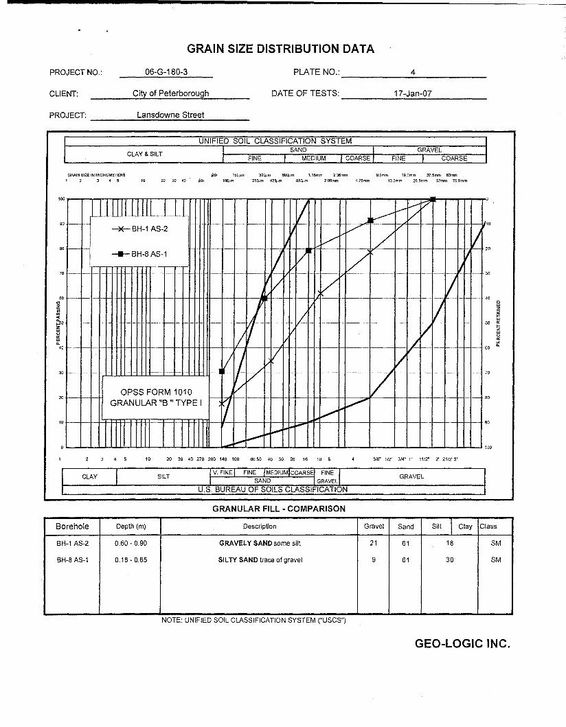
GRAIN SIZE DISTRIBUTION DATA
4PLATE NO.:--------------06-G-180-3PROJECT NO.:
17-Jan-07DATE OF TESTS:-----..;..;......;;..:.;~~-----
City of PeterboroughCLIENT:
PROJECT: ..:L:;;;;a~n.;;.sd:;.;o;;.;w.;.;.n..:e;...;S:;.;t~re;;.;e;.:.t _
CLAY & SILT
UNIFIED SOIL CLASSIFICATION SYSTEMI SAND II FINE I MEDIUM I COARSE I
GRAVELFINE I COARSE
III
GRAIN SIZE IN MiCROMETERS1 2 3 4 5 10
~Hh 150.lm 30QJm 60q.lm 1.18mm 2.36mm g,Smm 19.0mm 37.5mm 63mm20 30 40 6th 1Dq;.m 25(pm 425J,lrn 85Q.im 2.00mm 4.75mm 13.2mm 26.5mm 53mm 75.0mrn
v30
4 5 10 20 30 40 270 200 140 100 6050 40 30 20 16 10 8 3/8" 112" 3/4" 1" 1112" 2" 2112' 3"
I CLAY SILTI V. FINE I FINE IMEDIUMICOARSE! FINE II SAND I GRAVEll
GRAVEL IJ U.S. BUREAU OF SOILS CLASSIFICATION I
GRANULAR FILL· COMPARISON
Borehole Depth (m) Description Gravel Sand Silt I Clay Class
BH-1 AS-2 0.60 - 0.90 GRAVELY SAND some silt 21 61 18 SM
BH-8 AS-1 0.18 - 0.65 SILTY SAND trace of gravel 9 61 30 SM
NOTE: UNIFIED SOIL CLASSIFICATION SYSTEM ("USCS")
GEO-LOGIC INC.

GRAIN SIZE DISTRIBUTION DATA
PROJECT NO.: ___---.,;0;.;;6;...;-G:;..-...:...18::.;;0;...-3::..-. PLATE NO.: 5
CLIENT: __--=:C,;.:.itYI...0::..:f..:.P..::e:,:.:te:.:.;rb::..:o::.:,.ro::..:U:.;;9!:..:h--DATE OF TESTS: 17-Jan-07
PROJECT: Lansdown Street
"...............
.....- - . - -~
Vr I
V
/I
/I
. .. -
L.'~I
V...
...~
l- I..
""•
30
60
10
20
70
40
90
o
80
100
100
GRAVEL
10DIAMETER (mm)
FINE MEDIUM
0.1
SANDUNIFIED SOIL CLASSIFICATION SYSTEI'v
I V. FINE !FIN~ MEDIUM ! COARSE! FINE Ir SAND ! GRAVEL
SILT
0.01
CLAY & SILT
I
70
80
CLAY
90
o0.001
30
80
10
20
40
100
U.S. BUREAU OF SOILS CLASSIFICATION
SAMPLE No.DEPTH DESCRIPTION Gravel Sand Silt Clay CLASS.
(ELEVATION)
BH-3, AS-3 1.35 - 1.40 SILTY SAND with CLAY 3 56 26 15 SM
NOTE: UNIFIED SOIL CLASSIFICATION SYSTEM ("USeS")
GEO-LOGIC INC. Plate No.: 5
PROJECT NO.:
CLIENT:
PROJECT:
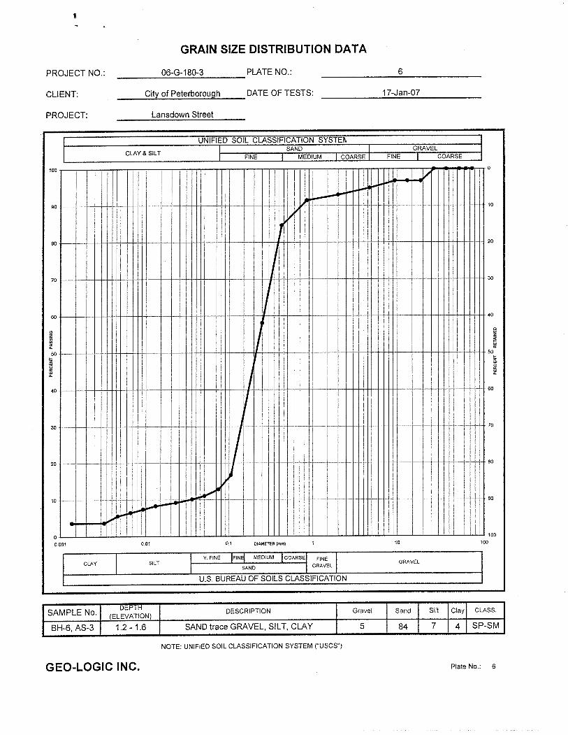
GRAIN SIZE DISTRIBUTION DATA
___-...:::.06;:.-.::G__-1:.::;8;:.0-..:;.3 PLATE NO.:
__-..;;.C.;.;.ityt...,.;;.of;..;P.....e;..;te.;;.;r..;;;b.;;.;or;.;;o..;;;u.:il,;9h...;...-__ DATE OF TESTS:
Lansdown Street
6
17-Jan-07
CLAY & SILT
UNIFIED SOIL CLASSIFICATION SYSTEfI.SAND
FINE MEDIUMGRAVEL
COARSE
100
90
80
70
60
40
30
20
10
~Jl/
...j",.ol....
vll --
II
J
IIII
III
J
I- - 1- - -- - --
~
~WI
~~-~ --l-- - .
... i-IJ.o.......
10
20
30
40
cw
~50...~
~
60
70
80
90
V. FINE IFIN~ MEDIUM I COARSEI FINE ISAND I GRAVEL
o0.001
CLAY I0.01
SILTII
0.1 DIAMETER (mm) 10
GRAVEL
100
100
U.S. BUREAU OF SOILS CLASSIFICATION
SAMPLE No.DEPTH DESCRIPTION Gravel I Sand Silt Clay CLASS.
(ELEVATION)
BH-6, AS-3 1.2 - 1.6 SAND trace GRAVEL, SILT, CLAY 5 I 84 7 4 SP-SM
NOTE: UNIFIED SOIL CLASSIFICATION SYSTEM ("USCS")
GEO-LOGIC INC. Plate No.: 6