Appendix D Hydrology and Hydraulics - St. Louis District D_… · Appendix D Hydrology and...
29
Draft Definite Project Report with Integrated Environmental Assessment Clarence Cannon National Wildlife Refuge HREP Appendix D Hydrology and Hydraulics
Transcript of Appendix D Hydrology and Hydraulics - St. Louis District D_… · Appendix D Hydrology and...
Draft Definite Project Report with Integrated Environmental Assessment Clarence Cannon National Wildlife Refuge HREP
Appendix D
Hydrology and Hydraulics

INTENTIONALLY LEFT BLANK

USACE | Hydrology and Hydraulics Appendix D 1
Hydrology and Hydraulics Appendix D
1. Introduction
1.1 Basis for Hydraulic Analysis
The project area is the entire existing aerial extent of the Clarence Cannon National Wildlife Refuge. This refuge is managed by the U.S. Fish and Wildlife Service (USFWS). A schematic of the existing configuration of the refuge is shown in FIGURE 1 and a conceptual flow diagram depicting drainage of the site is portrayed in FIGURE 2. The refuge consists of interior and exterior berms and a large number of management units, as well as creeks and ditches that are controlled by water control structures. An uncontrolled spillway also exists near the Mississippi River.
FIGURE 1. Clarence Cannon National Wildlife Refuge

USACE | Hydrology and Hydraulics Appendix D 2
FIGURE 2: Schematic showing existing drainage patterns of the site
The best topographic data available at the beginning of the Feasibility Phase was Scientific Assessment Strategy Team (SAST) data, which was collected in 1995 in response to the Flood of 1993 in the Upper Mississippi River Basin. These data are multi-resolution data that cover the geographic extent of the Upper Mississippi River Basin. A raster representation of these data was used for hydraulic analysis and modeling.
During the Feasibility Phase, ground surveys were conducted in proposed locations for water control structures and pump stations and at points along the interior and exterior berms. Surveys were also conducted of existing water control structures and of the berms in the immediate vicinity of these structures. These data were used with the SAST data to develop the hydraulic modeling and the preliminary design of features.
1.2 Pertinent Hydraulic Data
For hydraulic analysis and modeling, it was necessary to estimate Mississippi River mileage data for the refuge. The computer program DeLorme XMap 4.5 was used to construct curved lines between Mississippi River mile markers on U.S. Geological Survey (USGS) topographic mapping, along with lines drawn to key refuge locations to estimate mileage data. A graphic produced with this computer program showing lines used to determine Mississippi River mileage data is shown in FIGURE 3.

USACE | Hydrology and Hydraulics Appendix D 3
Mississippi River gages within the vicinity of the refuge that were used in the hydraulic analysis and modeling are located at Mosier Landing, Illinois (river mile 260.3), and at Lock & Dam No. 24 tailwater at Clarksville, Missouri (river mile 273.2).
FIGURE 3. Lines Used to Determine Mississippi River Mileage Data
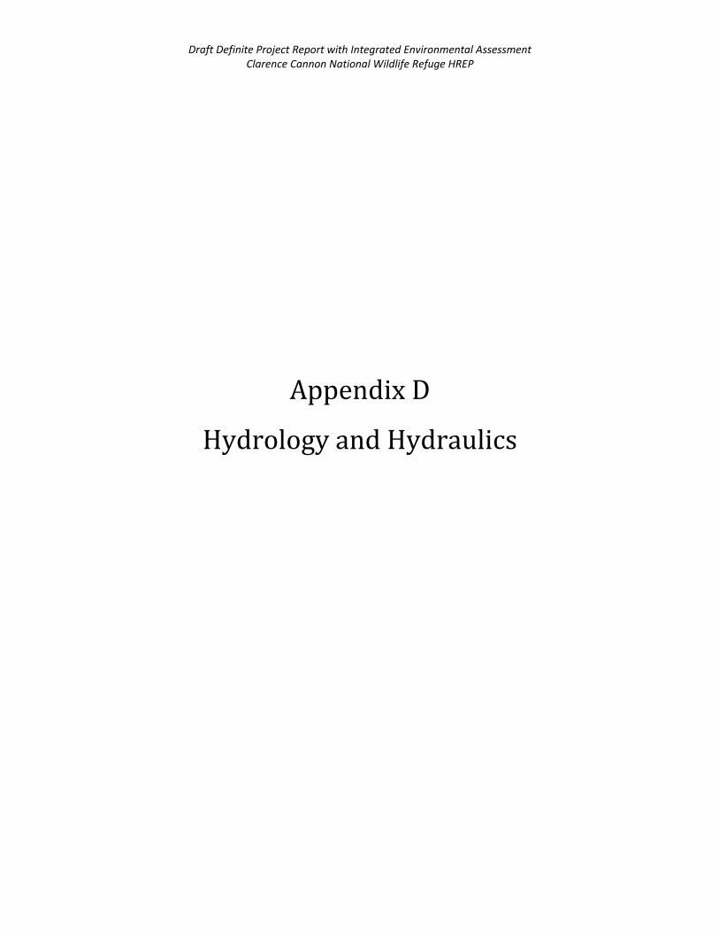
Data taken from the Upper Mississippi River System Flow Frequency Study (January 2004) were used to construct frequency flood profiles within the vicinity of the refuge. These frequency flood profiles and refuge key locations are shown in FIGURE 4. The profiles were constructed between the locations of the Lock & Dam No. 24 tailwater gage (river mile 273.2) and the Mosier Landing gage (river mile 260.3). Eight frequency flood profiles (500-, 200-, 100-, 50-, 25-, 10-, 05- and 02-year) were constructed.
USACE | Hydrology and Hydraulics Appendix D 4
FIGURE 4. Mississippi River Frequency Flood Profiles and Refuge Key Locations
The relationship of these frequency flood profiles to the refuge Mississippi River exterior berm affects refuge management to a certain extent. The Mississippi River exterior berm is equipped with an uncontrolled concrete spillway. This spillway allows water to flood the refuge as a Mississippi River flood is occurring so that the inside of the exterior berm has water against it if the flood eventually overtops the exterior berm. Water on the inside of the exterior berm will provide some protection to the exterior berm as water plunges over it from the Mississippi River flood. The spillway also allows water to leave the refuge as a flood is receding. The entire refuge is enclosed by an exterior berm, and the portion of this exterior berm that lies next to the Mississippi River contains the spillway.
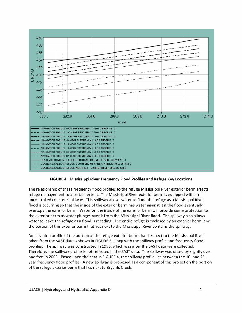
An elevation profile of the portion of the refuge exterior berm that lies next to the Mississippi River taken from the SAST data is shown in FIGURE 5, along with the spillway profile and frequency flood profiles. The spillway was constructed in 1996, which was after the SAST data were collected. Therefore, the spillway profile is not reflected in the SAST data. The spillway was raised by slightly over one foot in 2003. Based upon the data in FIGURE 4, the spillway profile lies between the 10- and 25-year frequency flood profiles. A new spillway is proposed as a component of this project on the portion of the refuge exterior berm that lies next to Bryants Creek.
USACE | Hydrology and Hydraulics Appendix D 5
FIGURE 5. Mississippi River Exterior Berm Profile (SAST Data), Spillway Profile and Frequency Flood
Profiles
Numerous water control structures of various types currently exist throughout the refuge. Field surveys of the vast majority of these structures were performed. The surveys were performed by a St. Louis District land surveyor during four site visits in 2012 (February, August (two), September) with automated survey equipment that made use of satellite technology. The parameters that were collected were structure type and material, shape of opening, size of opening (diameter if round, dimensions if rectangular) and invert elevation. The top-of-berm elevation above each structure was also surveyed. These surveys were conducted for use in hydraulic modeling of existing conditions, as well as to provide baseline data for use in hydraulic modeling of proposed conditions.
Elevation data for the surveys of existing water control structures were collected in the North American Vertical Datum of 1988 (NAVD88). Since both the SAST data and Mississippi River elevation data for nearby gages are available in the National Geodetic Vertical Datum of 1929 (NGVD29), it was decided to convert surveyed data to NGVD29 for hydraulic modeling (existing and proposed conditions). Therefore, it was necessary to determine a conversion factor.
Two procedures were employed to determine a conversion factor between NAVD88 and NGVD29. The first procedure involved surveying the Mississippi River water-surface elevation adjacent to the refuge during each of four site visits made to the refuge for water control structure surveying and recording the time of survey. Later, the Mississippi River water-surface elevation at the survey location was calculated

USACE | Hydrology and Hydraulics Appendix D 6
by linear interpolation based upon the closest-in-time Lock & Dam No. 24 tailwater and Mosier Landing automated gage readings available. The difference in the surveyed water-surface elevation and the calculated water-surface elevation was noted for each of five such surveys conducted at the four site visits. The results of this analysis are given in TABLE 1.
The second procedure to determine a conversion factor involved surveying a USFWS benchmark attached to the water control structure on Rabourn Slough on the eastern edge of the refuge near the Mississippi River during each of four site visits made to the refuge for water control structure surveying. Based upon discussions with USFWS personnel and other research, the datum of this benchmark was never definitively determined but it is believed that it is NGVD29. The difference in the surveyed elevation and the elevation imprinted on the benchmark was noted for each of five such surveys conducted at the four site visits. The results of this analysis are given in TABLE 2.
The results of these two procedures were considered. Based upon consultation with the St. Louis District land surveyor who performed the surveys, and upon surveying judgment and engineering judgment, a conversion factor of 0.8 foot was chosen. It was decided to add 0.8 foot to the elevations surveyed in NAVD88 to convert them to NGVD29.
TABLE 1. Results of First Procedure Used to Determine a Conversion Factor (NAVD88 to NGVD29)
Date of Survey
Time of
Survey (hours)
Mississippi River
at Lock & Dam No. 24
Tailwater Elevation
(feet NGVD29)
Mississippi River
at Survey Location
(river mile 261.85)
Interpolated Elevation
(feet NGVD29)
Mississippi River at Mosier Landing
Elevation (feet NGVD29)
Mississippi River
at Survey Location
(river mile 261.85)
Surveyed Elevation
(feet NAVD88)
Difference in Mississippi River
Interpolated Elevation
And Mississippi River
Surveyed Elevation
(feet NGVD29 – feet NAVD88)
08 Feb 2012
1630 436.89 435.41 435.21 434.462 0.95
02 Aug 2012
1400 435.72 434.85 434.73 434.195 0.65
29 Aug 2012
1000 434.96 434.62 434.57 433.901 0.72
17 Sep 2012
1600 434.66 434.63 434.63 433.934 0.70
17 Sep 2012
1600 434.66 434.63 434.63 433.885 0.75

USACE | Hydrology and Hydraulics Appendix D 7
TABLE 2. Results of Second Procedure Used to Determine a Conversion Factor (NAVD88 to NGVD29)
Date of Survey
Elevation Stamped on USFWS Benchmark on
Rabourn Slough Water Control Structure
(assumed as feet NGVD29)
Surveyed Elevation of USFWS Benchmark on
Rabourn Slough Water Control Structure
(feet NAVD88)
Difference in USFWS Benchmark Stamped Elevation
and USFWS Benchmark Surveyed Elevation
(feet NGVD29 – feet NAVD88)
08 Feb 2012 452.22 451.286 0.93
02 Aug 2012 452.22 451.386 0.83
29 Aug 2012 452.22 451.328 0.89
29 Aug 2012 452.22 451.407 0.81
17 Sep 2012 452.22 451.351 0.87
2. Redesign of the Refuge
2.1 Proposed Configuration for the Refuge
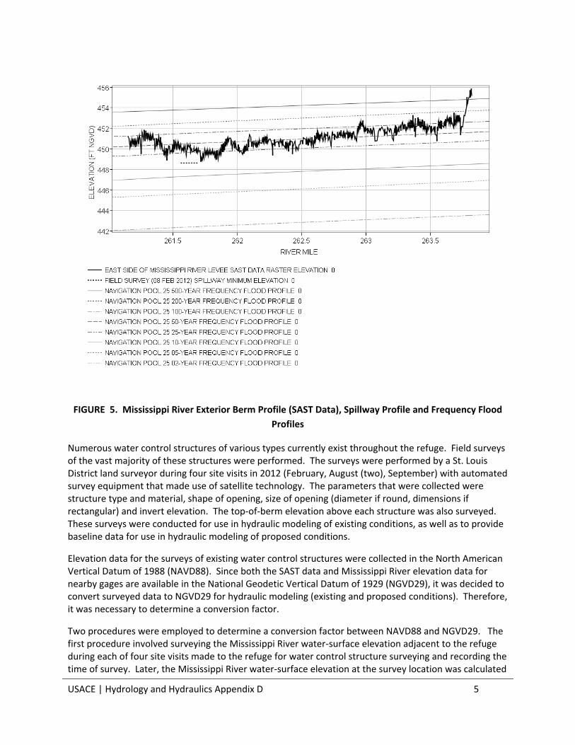
The proposed configuration for the refuge is shown in FIGURE 6 and future drainage pattern of the site with the tentatively selected plan is shown in FIGURE 7. It is proposed to divide the refuge into three units, two of which will be divided into subunits. North Unit will consist of MSU7 Subunit and Northern Subunit. South Unit will consist of Southwest Subunit, Central Subunit, Eastern Subunit, Big Pond Subunit and the existing Supply Pond. Riverside Unit will have no subunits and it will lie closest to the Mississippi River. It is planned that the water level within the Riverside Unit will primarily be allowed to rise and fall as the Mississippi River level rises and falls. North Unit and South Unit will both have water level management capabilities with the use of water control structures and pumping. Elevation-volume data have been calculated for the six proposed subunits. These data are shown in FIGURE 8.
2.2Hydraulic Data Used for Analysis of Riverside Unit
Hydraulic data was necessary for the analysis of the proposed Riverside Unit. The objective for the Riverside Unit is to allow the water level within it to rise and fall as the Mississippi River level rises and falls. The exterior berm on the south side of the Riverside Unit will be degraded to allow water to enter or leave the unit in response to the changing level of Bryants Creek and the Mississippi River. The water level within Bryants Creek adjacent to the refuge is highly influenced by the Mississippi River.
It was desired to determine a reasonable elevation to which to degrade the exterior berm on the south side of the Riverside Unit such that the varying water level within the unit would produce maximum ecological benefits. Based upon the land-surface elevations within the Riverside Unit taken from the SAST data, it was believed that a reasonable elevation for the exterior berm degradation would be 441.0 feet NGVD29. To determine the effect of using this elevation for the exterior berm degradation, 70 years of daily elevation data for the Mississippi River at Mosier Landing were examined to determine periods when elevation 441.0 feet NGVD29 was exceeded. The number of these periods, as well as the duration of them, was determined.

USACE | Hydrology and Hydraulics Appendix D 8
FIGURE 6. Proposed Plan Showing New Management Units (North, Riverside, and South Units)
USACE | Hydrology and Hydraulics Appendix D 9
FIGURE 7. Expected future drainage patterns of the site with the tentatively selected plan

USACE | Hydrology and Hydraulics Appendix D 10
FIGURE 8. Elevation-Volume Data for the Six Proposed Subunits
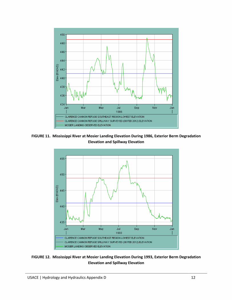
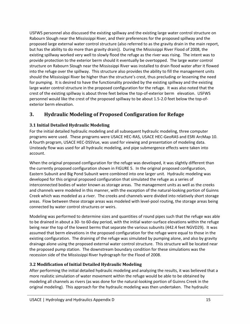
Plots of time versus the elevation of the Mississippi River at Mosier Landing during the period of 1941 through 2010 were developed. These plots also had a line indicating elevation 441.0 feet NGVD29, as well as a line indicating the elevation of the existing spillway (448.6 feet NGVD29) for reference. The Mosier Landing gage is located at Mississippi River mile 260.3, and the southeast corner of the refuge at the mouth of Bryants Creek is located at about mile 261.1. It is believed that using elevation data for the Mississippi River at Mosier Landing is a reasonable approximation for the river level at the southeast corner of the refuge at the mouth of Bryants Creek. Depending upon river conditions, the river elevation will be usually slightly higher at the southeast corner of the refuge than it will be at Mosier Landing but it won’t be lower. The period of analysis beginning in 1941 was chosen since 1941 was the first full year during which Lock & Dam No. 24, Lock & Dam No. 25 and Locks & Dam No. 26 were in operation.
Plots of time versus the elevation of the Mississippi River at Mosier Landing (including the proposed exterior berm degradation elevation and the spillway elevation) for 1941, 1970, 1986 and 1993 are shown in FIGURE 9 through FIGURE 11, respectively. These four years demonstrate varying conditions on the Mississippi River, with varying durations of exceedence of river elevation 441.0 feet NGVD29 at Mosier Landing. FIGURE 9 is included to show that it is possible that elevation 441.0 feet NGVD29 may not be exceeded during any given year. Thus, backflooding of the Riverside Unit is not a certainty in any given year. During 1941, this unit would not have been backflooded by the Mississippi River.

USACE | Hydrology and Hydraulics Appendix D 11
FIGURE 9. Mississippi River at Mosier Landing Elevation During 1941, Exterior Berm Degradation
Elevation and Spillway Elevation
FIGURE 10. Mississippi River at Mosier Landing Elevation During 1970, Exterior Berm Degradation
Elevation and Spillway Elevation
USACE | Hydrology and Hydraulics Appendix D 12
FIGURE 11. Mississippi River at Mosier Landing Elevation During 1986, Exterior Berm Degradation
Elevation and Spillway Elevation
FIGURE 12. Mississippi River at Mosier Landing Elevation During 1993, Exterior Berm Degradation
Elevation and Spillway Elevation

USACE | Hydrology and Hydraulics Appendix D 13
For the design of the proposed configuration of the refuge, it was necessary to determine the status of the numerous existing water control structures and the existing pump station. The status of the existing water control structures and the existing pump station is shown in FIGURE 13. Each structure and the pump station were given a status of either “Maintain”, “Remove” or “Remove and Replace”. Some of the existing structures will be left in place since it is anticipated that they may be of use in the future management of the refuge. Many of the existing water control structures will be removed since they will no longer be needed for management of an existing unit. The status denoted as “Remove and Replace” indicates locations where proposed water control structures will be located, which are all locations of existing structures (thus, the need to remove the existing structure). The existing pump station will be left in place.
FIGURE 13. Status of Existing Water Control Structures and Existing Pump Station
2.3 Proposed Reconfiguration of Portion of North-South Channel
An aerial photograph of a portion of the north-south channel within the south-central portion of the refuge is shown in FIGURE 14. Both the SAST data and field observation during site visits showed that the channel within the vicinity of the light-blue shaded cross sections was filled with sediment to a large extent. This sediment deposition is likely caused by the relatively low water speed through this area as the result of the two 90-degree turns that exist.

USACE | Hydrology and Hydraulics Appendix D 14
It is recommended that this portion of the channel be reconfigured such that the 90-degree turns are eliminated and the two north-south arms of this channel are connected by a smooth, curved transition. The hydraulic modeling that is discussed below maintained the configuration of this channel as it is, with the exception that the light-blue shaded cross sections were modified to eliminate sediment deposition. Hydraulic modeling during the Plans and Specifications Phase will take into account this proposed reconfiguration of the north-south channel.
FIGURE 14. Portion of North-South Ditch within South-Central Portion of Refuge
2.4 USFWS Preferences and Priorities for Management of the Refuge
USFWS personnel discussed their preferences and priorities for management of the refuge. Regarding pumping capacity, it is a priority to be able to pump water out of the refuge during overtopping flood events. The capacity of the existing pump station is sufficient for pumping water out of the refuge during non-flood conditions, but is insufficient during overtopping flood events which result in ponding of flood waters and subsequent forested and non-forested wetland damage. It is desired to be able to remove water from the refuge in 40 days or less. In terms of reaching target water levels for wetland management, USFWS desires to have the ability to pump water into the units in less than 7 days. The existing pump station is inadequate for pumping water into the units. The existing units take 7 days or longer to reach optimum water levels. Within a management unit, typically an eight-inch water depth over the highest terrain is the target water depth.
USACE | Hydrology and Hydraulics Appendix D 15
USFWS personnel also discussed the existing spillway and the existing large water control structure on Rabourn Slough near the Mississippi River, and their preferences for the proposed spillway and the proposed large external water control structure (also referred to as the gravity drain in the main report, but has the ability to do more than gravity drain)). During the Mississippi River Flood of 2008, the existing spillway worked very well to slowly flood the refuge as the river was rising. The intent was to provide protection to the exterior berm should it eventually be overtopped. The large water control structure on Rabourn Slough near the Mississippi River was installed to drain flood water after it flowed into the refuge over the spillway. This structure also provides the ability to fill the management units should the Mississippi River be higher than the structure’s crest, thus precluding or lessening the need for pumping. It is desired to have the functionality provided by the existing spillway and the existing large water control structure in the proposed configuration for the refuge. It was also noted that the crest of the existing spillway is about three feet below the top-of-exterior berm elevation. USFWS personnel would like the crest of the proposed spillway to be about 1.5-2.0 feet below the top-of-exterior berm elevation.
3. Hydraulic Modeling of Proposed Configuration for Refuge
3.1 Initial Detailed Hydraulic Modeling
For the initial detailed hydraulic modeling and all subsequent hydraulic modeling, three computer programs were used. These programs were USACE HEC-RAS, USACE HEC-GeoRAS and ESRI ArcMap 10. A fourth program, USACE HEC-DSSVue, was used for viewing and presentation of modeling data. Unsteady flow was used for all hydraulic modeling, and pipe submergence effects were taken into account.
When the original proposed configuration for the refuge was developed, it was slightly different than the currently proposed configuration shown in FIGURE 5. In the original proposed configuration, Eastern Subunit and Big Pond Subunit were combined into one larger unit. Hydraulic modeling was developed for this original proposed configuration that simulated the refuge as a series of interconnected bodies of water known as storage areas. The management units as well as the creeks and channels were modeled in this manner, with the exception of the natural-looking portion of Guinns Creek which was modeled as a river. The creeks and channels were divided into relatively short storage areas. Flow between these storage areas was modeled with level-pool routing, the storage areas being connected by water control structures or weirs.
Modeling was performed to determine sizes and quantities of round pipes such that the refuge was able to be drained in about a 30- to 60-day period, with the initial water-surface elevations within the refuge being near the top of the lowest berms that separate the various subunits (442.4 feet NGVD29). It was assumed that berm elevations in the proposed configuration for the refuge were equal to those in the existing configuration. The draining of the refuge was simulated by pumping alone, and also by gravity drainage alone using the proposed external water control structure. This structure will be located near the proposed pump station. The downstream boundary condition for these simulations was the recession side of the Mississippi River hydrograph for the Flood of 2008.
3.2 Modification of Initial Detailed Hydraulic Modeling
After performing the initial detailed hydraulic modeling and analyzing the results, it was believed that a more realistic simulation of water movement within the refuge would be able to be obtained by modeling all channels as rivers (as was done for the natural-looking portion of Guinns Creek in the original modeling). This approach for the hydraulic modeling was then undertaken. The hydraulic
USACE | Hydrology and Hydraulics Appendix D 16
structure sizes that were determined for the original proposed configuration were maintained to test them with the new modeling approach, with the exception that separate structures were added for Eastern Subunit and Big Pond Subunit.
The draining of the refuge was simulated by pumping alone using this second modeling approach, with the initial water-surface elevations within the refuge being near the top of the lowest berms that separate the various subunits (442.4 feet NGVD29). Some difficulty was encountered with the simulations of draining the refuge by pumping in that some locations along the channels tended to run out of flowing water during the later portion of a simulation. Lack of flowing water causes an unsteady-flow simulation to cease. The fact that simulations were not able to continue as long as desired resulted in management units that are located farthest from the pump station to have water remaining in them.
During the modeling process, it was observed that the surveyed invert elevations of the existing water control structures were often lower by about 0.5-3.5 feet than the lowest channel or creek elevations shown on the SAST data in the vicinity of the structure. This observation may indicate the fact that there was water within the channels and creek when the SAST data were collected. Therefore, the channels and creek may have not necessarily been modeled in their true form. This fact is likely a contributing factor to some locations along the channels tending to run out of flowing water during the later portion of a simulation. The channels could be, in reality, deeper than they are simulated to be and thus reach their apparent bottom.
For modeling purposes, the channel or creek near a given structure was adjusted downward to accommodate the structure. However, no attempt was made to adjust the full length of the channels and creek. Also, no channel or creek surveys were acquired during the four site visits in 2012. During the Plans and Specifications Phase, it is anticipated that topographic data of the refuge as it currently exists will be collected along with channel and creek survey data.
During the work on the modification of the initial detailed hydraulic modeling, removal and replacement of the channel and creek water control structures was also studied since they were deemed to be undersized. One of these structures that crosses Guinns Creek on a gravel road that is located just north of the USFWS Management Office is on a berm that is proposed to be removed. USFWS personnel were asked if this structure could be removed in the proposed configuration of the refuge, and they approved this action during late January 2013. Thus, this structure was removed from the hydraulic modeling. Also, a proposed water control structure to be used for both gravity drainage and intentional flooding of the refuge was studied.
3.3 Summary of Proposed Water Control Structures
A summary of the proposed water control structures is given below.
3.3.1 Proposed Management Subunit Water Control Structures
MSU 7 Subunit Structure: near the southeast corner of existing management unit MSU 7, and at the location of the existing MSU 7 south structure
Northern Subunit West Structure: at the south end of existing management unit GTR-7, and at the location of the existing GTR-7 structure
Northern Subunit East Structure: near the northeast corner of existing management unit MSU 2, and at the location of an existing culvert under the refuge’s main east-west road
Eastern Subunit Structure: near the southwest corner of existing management unit MSU 12; near the southwest corner of proposed Eastern Subunit

USACE | Hydrology and Hydraulics Appendix D 17
Big Pond Subunit Structure: near the northeast corner of existing management unit Supply Pond, and at the location of the existing structure on the western border of existing management unit Big Pond
Central Subunit Structure: on the southern border of existing management unit MSU 1, and at the location of the existing MSU 1 structure
Southwest Subunit Structure: in the northern portion of existing management unit MSU 9, and at the location of the existing MSU 9 structure
Management Subunit Water Control
Structure
Quantity and Diameter of Round
Pipes
Cross- Sectional
Area (square
feet)
Invert Elevation
(feet NGVD29)*
Top-of-Berm Elevation
(feet NGVD29)**
MSU 7 Subunit 6 5.0-foot 117.6 434.6 444.5
Northern Subunit West 3 5.0-foot 58.8 435.0 443.3
Northern Subunit East 3 5.0-foot 58.8 438.0 445.1
Eastern Subunit 3 5.0-foot 58.8 436.5 445.2
Big Pond Subunit 3 5.0-foot 58.8 436.5 445.2
Central Subunit 3 4.0-foot 37.5 438.3 445.7
Southwest Subunit 3 5.0-foot 58.8 437.8 445.3 * Equal to surveyed invert elevations of existing water control structures at the same site. (The invert elevation for the existing structure at the
site of the proposed Northern Subunit West Structure was not able to be surveyed. The invert elevation for this proposed structure was based
upon that of the MSU 7 structure, SAST topographic data and judgment.)
** Equal to surveyed top-of-berm elevations at existing water control structures.
3.3.2 Proposed Creek and Channel Water Control Structures
Guinns Creek Structure: under the main east-west road
South Channel Structure: under the north-south road that leads to the existing pump station
Central Channel Structure: under the east-west road that forms the southern border of existing management unit MSU 1
Creek and Channel Water Control
Structure
Quantity and Diameter of Round
Pipes
Cross- Sectional
Area (square
feet)
Invert Elevation
(feet NGVD29)*
Top-of-Berm Elevation
(feet NGVD29)**
Guinns Creek 3 5.0-foot 58.8 434.0 445.3
South Channel 3 5.0-foot 58.8 433.5 445.6

USACE | Hydrology and Hydraulics Appendix D 18
Central Channel 3 5.0-foot 58.8 435.0 445.3
* Equal to surveyed invert elevations of existing water control structures at the same site.
** Equal to surveyed top-of-berm elevations at existing water control structures.
3.3.3 Proposed External Water Control Structure
External Structure: on the north-south ditch along the western border of proposed Big Pond
Subunit
Quantity and Diameter of Round
Pipes
Cross- Sectional
Area (square
feet)
Invert Elevation
(feet NGVD29)*
Top-of-Berm Elevation
(feet NGVD29)**
External Structure 5 6.0-foot 141.3 437.3 451.0 * Equal to the surveyed invert elevation of the existing water control structure on Rabourn Slough.
** Equal to the SAST terrain data elevation.
3.4 Optimization of Sizes for Proposed Water Control Structures
The water control structure sizes determined with the initial detailed hydraulic modeling were found to be of sufficient size to drain the refuge in a timely manner when used with the modified modeling. For a given structure, the performance of several different pipe diameters was simulated. Also, various quantities of these pipe diameters were also simulated. The intent of simulating several different pipe diameters, as well as different numbers of pipes, for a given structure was to determine the optimal configuration such that the necessary water flow would occur without having excess capacity. This optimization analysis was performed in a simulation of what might have been the post-flood drainage scenario of the refuge on the west side of the proposed setback berm for the Mississippi River Flood of 2008 had the proposed project been in place. This simulation began with gravity drainage and concluded with drainage by pumping. The change from gravity drainage to pumping for releasing water from the refuge was done in response to the fact that the Mississippi River began rising again after it had been falling throughout the early portion of the simulation. Initial water-surface elevations within the refuge were near the top of the lowest berms that separate the various subunits (442.4 feet NGVD29).
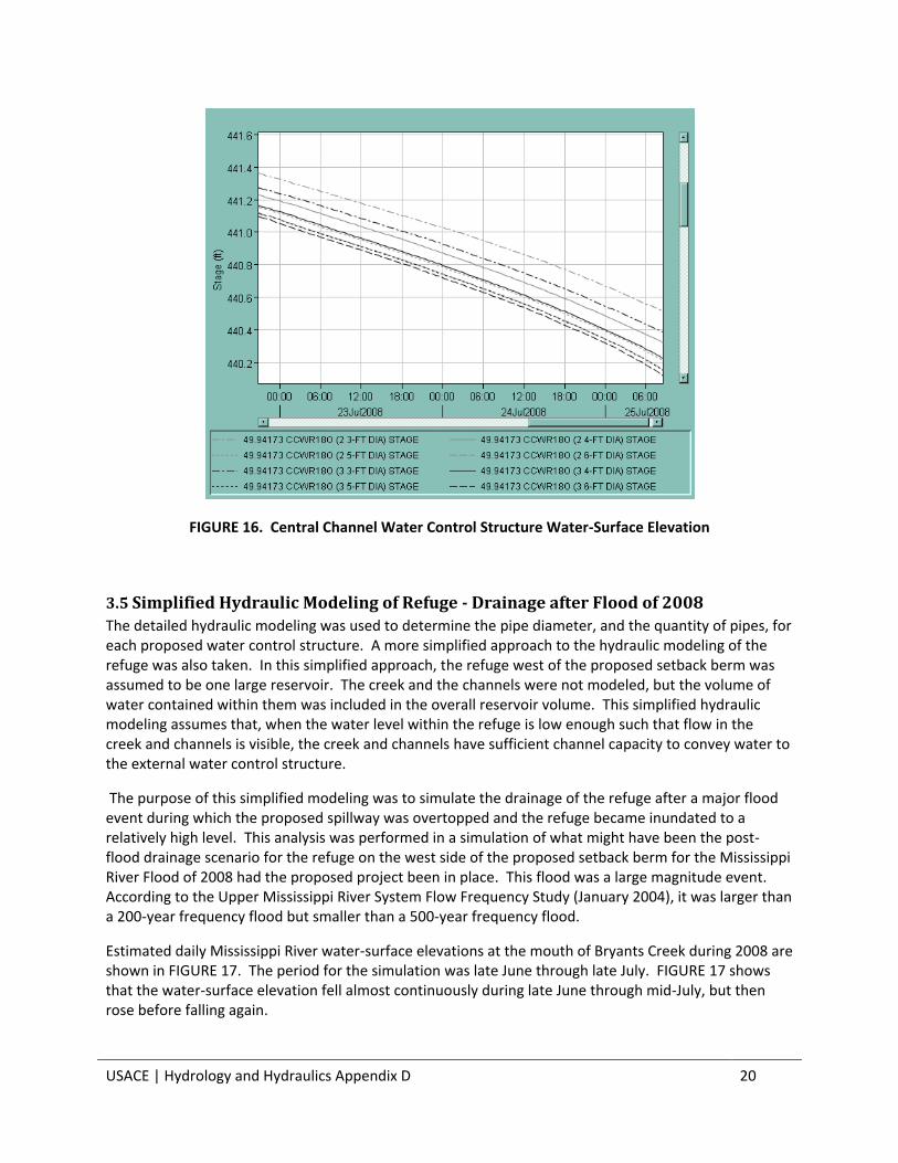
Some of the results of this optimization analysis for the Central Channel water control structure are given in FIGURE 15 and FIGURE 16. In the initial detailed hydraulic modeling, it was determined that three five-foot diameter pipes would be used for this structure. The optimization analysis for this structure involved holding all modeled parameters constant with the exception of the Central Channel structure pipe diameter and quantities. Four different pipe diameters (three, four, five and six feet) were examined and two different quantities were used (two pipes and three pipes), resulting in eight different scenarios.
FIGURE 15 shows cumulative flow (i.e., the total volume of flow) for the entire duration of the simulation. Pipe arrangements that produced higher cumulative flow during the simulation were more desirable. The curves for three five-foot pipes and two six-foot pipes overlap one another. The added

USACE | Hydrology and Hydraulics Appendix D 19
benefit of the three six-foot pipes over the two arrangements mentioned in the previous sentence is not overwhelmingly large. Thus, the original choice of three five-foot diameter pipes was selected.
FIGURE 14 shows water-surface elevation for about the later third of the simulation. Pipe arrangements that produced lower water-surface elevations during the simulation were more desirable. As in FIGURE 13, the curves for three five-foot pipes and two six-foot pipes overlap one another. As concluded from FIGURE 13, the added benefit of the three six-foot pipes is not overwhelmingly large and the original choice of three five-foot diameter pipes is acceptable.
FIGURE 15. Central Channel Water Control Structure Cumulative Flow (Total Volume of Flow)
USACE | Hydrology and Hydraulics Appendix D 20
FIGURE 16. Central Channel Water Control Structure Water-Surface Elevation
3.5 Simplified Hydraulic Modeling of Refuge - Drainage after Flood of 2008
The detailed hydraulic modeling was used to determine the pipe diameter, and the quantity of pipes, for each proposed water control structure. A more simplified approach to the hydraulic modeling of the refuge was also taken. In this simplified approach, the refuge west of the proposed setback berm was assumed to be one large reservoir. The creek and the channels were not modeled, but the volume of water contained within them was included in the overall reservoir volume. This simplified hydraulic modeling assumes that, when the water level within the refuge is low enough such that flow in the creek and channels is visible, the creek and channels have sufficient channel capacity to convey water to the external water control structure.
The purpose of this simplified modeling was to simulate the drainage of the refuge after a major flood event during which the proposed spillway was overtopped and the refuge became inundated to a relatively high level. This analysis was performed in a simulation of what might have been the post-flood drainage scenario for the refuge on the west side of the proposed setback berm for the Mississippi River Flood of 2008 had the proposed project been in place. This flood was a large magnitude event. According to the Upper Mississippi River System Flow Frequency Study (January 2004), it was larger than a 200-year frequency flood but smaller than a 500-year frequency flood.
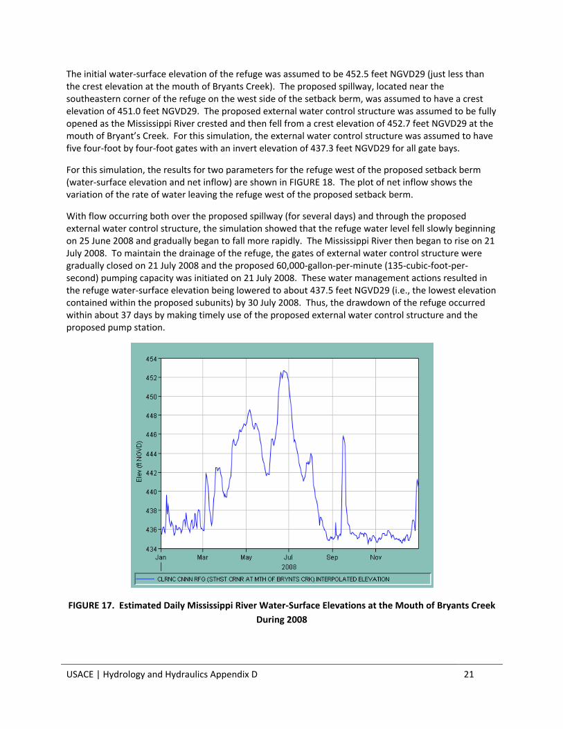
Estimated daily Mississippi River water-surface elevations at the mouth of Bryants Creek during 2008 are shown in FIGURE 17. The period for the simulation was late June through late July. FIGURE 17 shows that the water-surface elevation fell almost continuously during late June through mid-July, but then rose before falling again.
USACE | Hydrology and Hydraulics Appendix D 21
The initial water-surface elevation of the refuge was assumed to be 452.5 feet NGVD29 (just less than the crest elevation at the mouth of Bryants Creek). The proposed spillway, located near the southeastern corner of the refuge on the west side of the setback berm, was assumed to have a crest elevation of 451.0 feet NGVD29. The proposed external water control structure was assumed to be fully opened as the Mississippi River crested and then fell from a crest elevation of 452.7 feet NGVD29 at the mouth of Bryant’s Creek. For this simulation, the external water control structure was assumed to have five four-foot by four-foot gates with an invert elevation of 437.3 feet NGVD29 for all gate bays.
For this simulation, the results for two parameters for the refuge west of the proposed setback berm (water-surface elevation and net inflow) are shown in FIGURE 18. The plot of net inflow shows the variation of the rate of water leaving the refuge west of the proposed setback berm.
With flow occurring both over the proposed spillway (for several days) and through the proposed external water control structure, the simulation showed that the refuge water level fell slowly beginning on 25 June 2008 and gradually began to fall more rapidly. The Mississippi River then began to rise on 21 July 2008. To maintain the drainage of the refuge, the gates of external water control structure were gradually closed on 21 July 2008 and the proposed 60,000-gallon-per-minute (135-cubic-foot-per-second) pumping capacity was initiated on 21 July 2008. These water management actions resulted in the refuge water-surface elevation being lowered to about 437.5 feet NGVD29 (i.e., the lowest elevation contained within the proposed subunits) by 30 July 2008. Thus, the drawdown of the refuge occurred within about 37 days by making timely use of the proposed external water control structure and the proposed pump station.
FIGURE 17. Estimated Daily Mississippi River Water-Surface Elevations at the Mouth of Bryants Creek
During 2008

USACE | Hydrology and Hydraulics Appendix D 22
FIGURE 18. Refuge West of Proposed Setback Berm Water-Surface Elevation and Net Inflow for Flood
of 2008 Drainage Simulation
This simplified hydraulic modeling provided a simulation of the drainage of the refuge had the proposed project been in place during a major flood event with spillway overtopping (specifically the Flood of 2008), but excluding much of the detail of the hydraulic modeling described above. The detailed hydraulic modeling described above was necessary to determine the sizes for the proposed internal water control structures.
3.6 Simplified Hydraulic Modeling of Refuge - Drainage after Flood of 1993
A simulation of the drainage of the refuge after another major flood event during which the proposed spillway was overtopped and the refuge became inundated to a relatively high level was performed. This analysis was performed in a simulation of what might have been the post-flood drainage scenario for the refuge on the west side of the proposed setback berm for the Mississippi River Flood of 1993 had the proposed project been in place. This flood, like the Flood of 2008, was a large magnitude event. According to the Upper Mississippi River System Flow Frequency Study (January 2004), it was larger than a 500-year frequency flood.
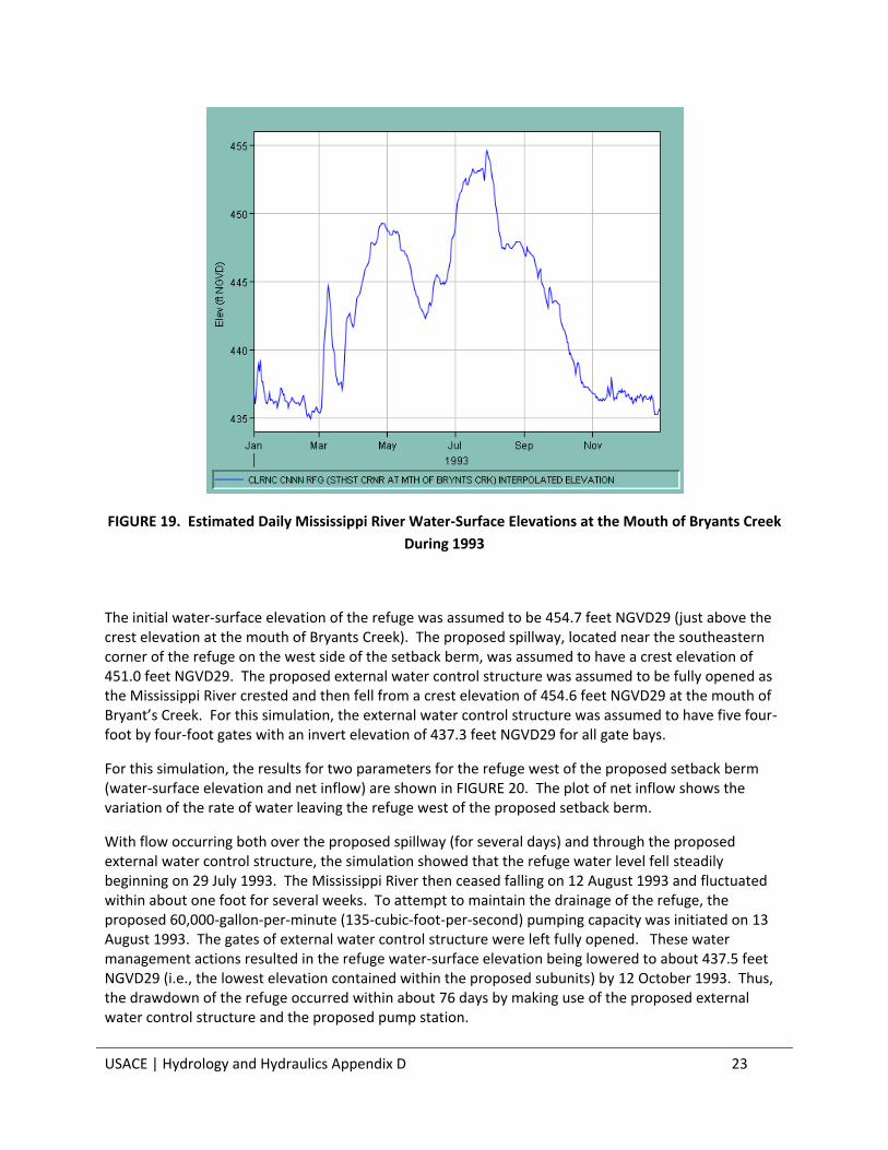
Estimated daily Mississippi River water-surface elevations at the mouth of Bryants Creek during 1993 are shown in FIGURE 19. The period for the simulation was late July through mid-October. FIGURE 19 shows that the water-surface elevation fell almost continuously during late July through mid-August, but then became more staggered in its behavior while exhibiting a slower fall.
USACE | Hydrology and Hydraulics Appendix D 23
FIGURE 19. Estimated Daily Mississippi River Water-Surface Elevations at the Mouth of Bryants Creek
During 1993
The initial water-surface elevation of the refuge was assumed to be 454.7 feet NGVD29 (just above the crest elevation at the mouth of Bryants Creek). The proposed spillway, located near the southeastern corner of the refuge on the west side of the setback berm, was assumed to have a crest elevation of 451.0 feet NGVD29. The proposed external water control structure was assumed to be fully opened as the Mississippi River crested and then fell from a crest elevation of 454.6 feet NGVD29 at the mouth of Bryant’s Creek. For this simulation, the external water control structure was assumed to have five four-foot by four-foot gates with an invert elevation of 437.3 feet NGVD29 for all gate bays.
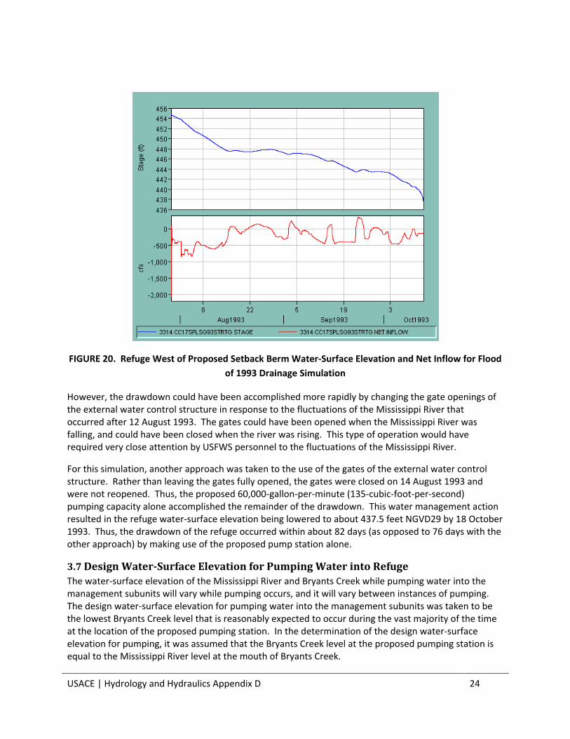
For this simulation, the results for two parameters for the refuge west of the proposed setback berm (water-surface elevation and net inflow) are shown in FIGURE 20. The plot of net inflow shows the variation of the rate of water leaving the refuge west of the proposed setback berm.
With flow occurring both over the proposed spillway (for several days) and through the proposed external water control structure, the simulation showed that the refuge water level fell steadily beginning on 29 July 1993. The Mississippi River then ceased falling on 12 August 1993 and fluctuated within about one foot for several weeks. To attempt to maintain the drainage of the refuge, the proposed 60,000-gallon-per-minute (135-cubic-foot-per-second) pumping capacity was initiated on 13 August 1993. The gates of external water control structure were left fully opened. These water management actions resulted in the refuge water-surface elevation being lowered to about 437.5 feet NGVD29 (i.e., the lowest elevation contained within the proposed subunits) by 12 October 1993. Thus, the drawdown of the refuge occurred within about 76 days by making use of the proposed external water control structure and the proposed pump station.
USACE | Hydrology and Hydraulics Appendix D 24
FIGURE 20. Refuge West of Proposed Setback Berm Water-Surface Elevation and Net Inflow for Flood
of 1993 Drainage Simulation
However, the drawdown could have been accomplished more rapidly by changing the gate openings of the external water control structure in response to the fluctuations of the Mississippi River that occurred after 12 August 1993. The gates could have been opened when the Mississippi River was falling, and could have been closed when the river was rising. This type of operation would have required very close attention by USFWS personnel to the fluctuations of the Mississippi River.
For this simulation, another approach was taken to the use of the gates of the external water control structure. Rather than leaving the gates fully opened, the gates were closed on 14 August 1993 and were not reopened. Thus, the proposed 60,000-gallon-per-minute (135-cubic-foot-per-second) pumping capacity alone accomplished the remainder of the drawdown. This water management action resulted in the refuge water-surface elevation being lowered to about 437.5 feet NGVD29 by 18 October 1993. Thus, the drawdown of the refuge occurred within about 82 days (as opposed to 76 days with the other approach) by making use of the proposed pump station alone.
3.7 Design Water-Surface Elevation for Pumping Water into Refuge
The water-surface elevation of the Mississippi River and Bryants Creek while pumping water into the management subunits will vary while pumping occurs, and it will vary between instances of pumping. The design water-surface elevation for pumping water into the management subunits was taken to be the lowest Bryants Creek level that is reasonably expected to occur during the vast majority of the time at the location of the proposed pumping station. In the determination of the design water-surface elevation for pumping, it was assumed that the Bryants Creek level at the proposed pumping station is equal to the Mississippi River level at the mouth of Bryants Creek.

USACE | Hydrology and Hydraulics Appendix D 25
An assumption that was made in choosing the design water-surface elevation for pumping water into the management subunits is that Lock & Dam No. 25 will be fully operational. It was also assumed that this structure will be maintaining a navigation pool upstream of it with its tainter gates and roller gates if the nine-foot depth required for commercial navigation is not occurring naturally.
To determine the design water-surface elevation for pumping water into the management subunits, Mississippi River elevation duration data in the vicinity of the proposed pumping station during the years 1941 through 2010 were examined. The period of analysis beginning in 1941 was chosen since 1941 was the first full year during which Lock & Dam No. 24, Lock & Dam No. 25 and Locks & Dam No. 26 were in operation.
Mississippi River elevation duration data for the river gages at both Lock & Dam No. 24 tailwater (river mile 273.2) and Mosier Landing (river mile 260.3) were plotted in FIGURE 19 for seven different percentages, and a straight line was drawn between these points for each individual percentage. The percentages chosen were 99, 90, 80, 70, 60, 50 and 40 percent. Thus, a large range of duration data was examined to determine a reasonable design water-surface elevation for pumping water into the management subunits. Also shown in FIGURE 21 is the approximate location of the mouth of Bryants Creek (Mississippi River mile 261.1). The water-surface elevations in the vicinity of the proposed pumping station for the 90, 80 and 70 percent durations are about 434.2, 434.5 and 434.8 feet NGVD29, respectively. Using the 90-percent duration as an example, another way to state the meaning of this information is that the Mississippi River water level at the mouth of Bryants Creek was at or above elevation 434.2 feet NGVD29 90 percent of the time during 1941 through 2010.

USACE | Hydrology and Hydraulics Appendix D 26
FIGURE 21. Mississippi River Elevation Duration Data for 1941-2010
Based upon the data given in FIGURE 21 and upon engineering judgment, the design water-surface elevation for pumping water into the management subunits of about 434.5 feet NGVD29 was chosen. This elevation corresponds to a duration value of about 80 percent. It should be noted that maximum regulated pool elevation at Lock & Dam No. 25 is 434.0 feet NGVD29. Thus, within the full length of Navigation Pool No. 25, the water-surface elevation should always be at least 434.0 feet NGVD29 while a navigation pool is being maintained upstream of Lock & Dam No. 25 with its tainter gates and roller gates if the nine-foot depth required for commercial navigation is not occurring naturally.
4. Concluding Discussion
4.1 Use of Box Culverts to Approximate Proposed Round Structures
Most hydraulic modeling performed thus far has employed round pipes for the proposed water control structures. In a few cases, various structures have been modeled as box culverts. To facilitate the production of technical drawings for the proposed water control structures, the decision was made by the Project Design Team to produce drawings of box culverts of all proposed water control structures. Accordingly, proposed structures that had been modeled as round pipes were converted to box culverts based upon an equivalent or slightly larger cross-sectional area. Invert elevations that were selected for the proposed round pipes were maintained for the box culverts. During the Plans and Specifications Phase, decisions will be made for each proposed structure regarding its shape.
USACE | Hydrology and Hydraulics Appendix D 27
4.2 Anticipated Work Planned for Plans and Specifications Phase
During the Plans and Specifications Phase, it is anticipated that topographic data of the refuge as it currently exists will be collected. Channel and creek survey data will also be collected. This information will be used to revise the hydraulic modeling. The revised modeling will be used to reevaluate the proposed water control structures and to develop optimized sizes for them. The proposed reconfiguration of the north-south channel within the south-central portion of the refuge discussed above will be incorporated into the revised hydraulic modeling.
Simulations of the operation of the proposed project for major floods will be performed with the revised hydraulic modeling. These major floods will include the floods of 1973, 1993, 2008 and 2013. Other floods may be included. Simulations of low-flow operation of the refuge with the proposed project will also be performed. These simulations will be performed to determine the expected performance of the proposed project under varied hydraulic conditions. This work may yield suggestions for USFWS personnel regarding management of the proposed project.
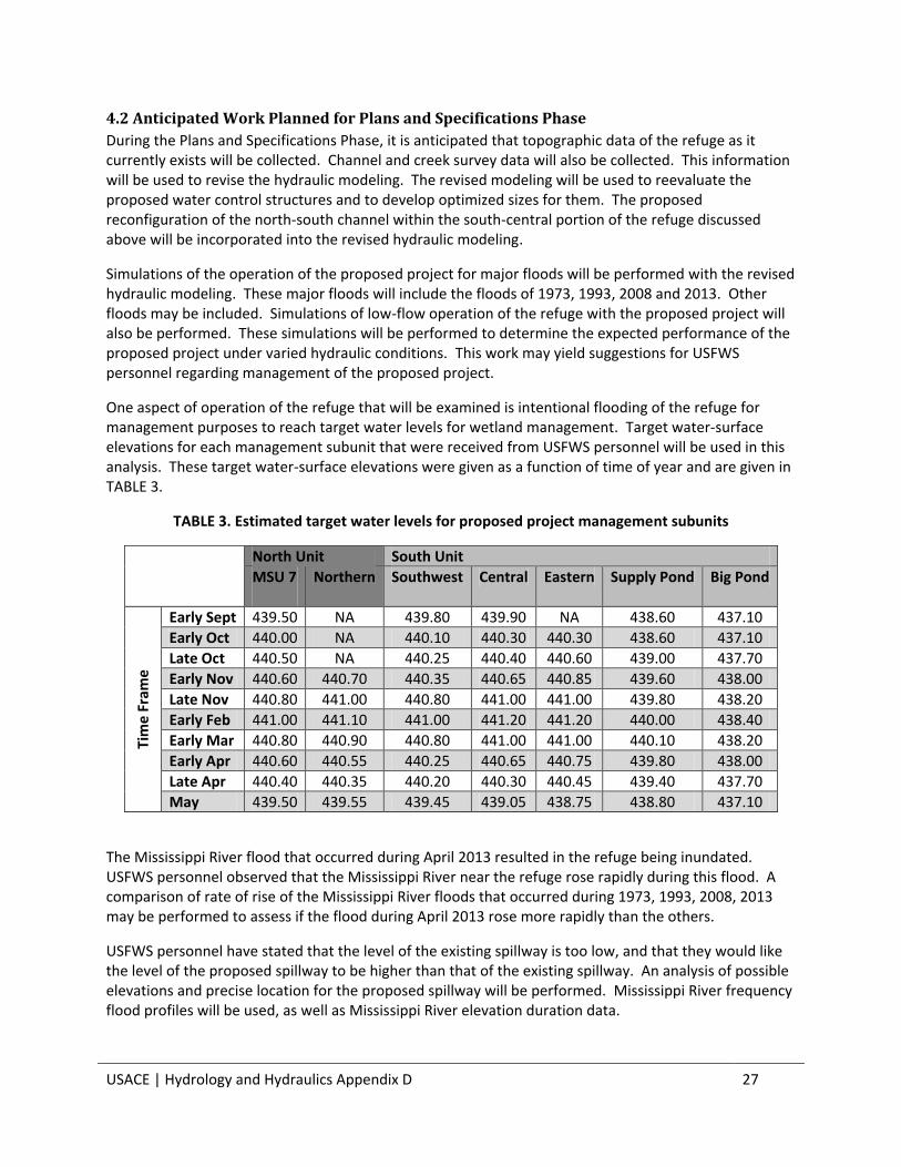
One aspect of operation of the refuge that will be examined is intentional flooding of the refuge for management purposes to reach target water levels for wetland management. Target water-surface elevations for each management subunit that were received from USFWS personnel will be used in this analysis. These target water-surface elevations were given as a function of time of year and are given in TABLE 3.
TABLE 3. Estimated target water levels for proposed project management subunits
North Unit South Unit
MSU 7
Northern Southwest Central Eastern Supply Pond Big Pond
Tim
e F
ram
e
Early Sept 439.50 NA 439.80 439.90 NA 438.60 437.10
Early Oct 440.00 NA 440.10 440.30 440.30 438.60 437.10
Late Oct 440.50 NA 440.25 440.40 440.60 439.00 437.70
Early Nov 440.60 440.70 440.35 440.65 440.85 439.60 438.00
Late Nov 440.80 441.00 440.80 441.00 441.00 439.80 438.20
Early Feb 441.00 441.10 441.00 441.20 441.20 440.00 438.40
Early Mar 440.80 440.90 440.80 441.00 441.00 440.10 438.20
Early Apr 440.60 440.55 440.25 440.65 440.75 439.80 438.00
Late Apr 440.40 440.35 440.20 440.30 440.45 439.40 437.70
May 439.50 439.55 439.45 439.05 438.75 438.80 437.10
The Mississippi River flood that occurred during April 2013 resulted in the refuge being inundated. USFWS personnel observed that the Mississippi River near the refuge rose rapidly during this flood. A comparison of rate of rise of the Mississippi River floods that occurred during 1973, 1993, 2008, 2013 may be performed to assess if the flood during April 2013 rose more rapidly than the others.
USFWS personnel have stated that the level of the existing spillway is too low, and that they would like the level of the proposed spillway to be higher than that of the existing spillway. An analysis of possible elevations and precise location for the proposed spillway will be performed. Mississippi River frequency flood profiles will be used, as well as Mississippi River elevation duration data.