
APPENDIX C STORM WATER POLLUTION PREVENTION PLAN · This Storm Water Pollution Prevention Plan ......
54
APPENDIX C STORM WATER POLLUTION PREVENTION PLAN
Transcript of APPENDIX C STORM WATER POLLUTION PREVENTION PLAN · This Storm Water Pollution Prevention Plan ......

APPENDIX C
STORM WATER POLLUTION PREVENTION PLAN

Metromedia Draft Mitigated Negative Declaration C-1
TABLE OF CONTENTSSTORM WATER POLLUTION PREVENTION PLAN
CHAPTER 1.0 _________________________________________________ 3GENERAL PROJECT INFORMATION
1.1 Overview ....................................................................................................................... 3
1.2 Linear Project Characteristics .......................................................................................... 4
1.3 Project Responsibilities ................................................................................................... 5
1.4 Total Area Estimate ........................................................................................................ 5
1.5 Site Map and Drainage .................................................................................................... 6
1.6 Receiving Waters............................................................................................................ 6
1.7 Wetlands ........................................................................................................................ 6
CHAPTER 2.0 _________________________________________________ 7POTENTIAL SOURCES OF POLLUTANTS
2.1 Description of Installation Activities ................................................................................ 7
2.2 Potentially Harzardous Materials Associated with Installation Activities ............................ 7
2.3 Non-Harzardous Materials Associated with Installation Activities...................................... 8
CHAPTER 3.0 _________________________________________________ 9BMPS FOR STORM WATER POLLUTION PREVENTION
3.1 General BMPs................................................................................................................ 9
3.2 Specific BMPs For Potentially Hazardous Materials.......................................................... 9
3.3 Overall Spill Response Coordination ...............................................................................12
3.4 Spill Containment Procedures.........................................................................................14
3.5 Notifications .................................................................................................................17
CHAPTER 4.0 ________________________________________________ 19EROSION AND SEDIMENT CONTROL MEASURES
4.1 General Specifications....................................................................................................19
4.2 Specific BMPs For Erosion and Sediment Control............................................................20
4.3 BMPs for post Installation / Soil Stabilization ..................................................................26

Appendix C — Storm Water Pollution Prevention Plan
C-2 Metromedia Draft Mitigated Negative Declaration
CHAPTER 5.0 ________________________________________________ 28INSPECTION, MAINTENANCE, AND RECORD KEEPING
5.1 Inspection and Maintenance ...........................................................................................28
5.2 Inspection Frequency .....................................................................................................29
5.3 Documentation of Inspections .........................................................................................29
5.4 Record Keeping and Internal Reporting Procedures .........................................................30
CHAPTER 6.0 ________________________________________________ 31CHANGES AND AMENDMENTS TO THE SWPPP
CHAPTER 7.0 ________________________________________________ 32TRAINING
CHAPTER 8.0 ________________________________________________ 33CERTIFICATION
ATTACHMENT I- III___________________________________________ 34PROJECT SEGMENT DESCRIPTION
MASTER LIST OF JURISDICTIONAL FEATURES
CALIFORNIA CONSTRUCTION HANDBOOK BMPS
ATTACHMENT IV ____________________________________________ 35MONITORING AND REPORTING FORMS
ATTACHMENT V_____________________________________________ 51NOTICE OF INTENT

Appendix C — Storm Water Pollution Prevention Plan
Metromedia Draft Mitigated Negative Declaration C-3
CHAPTER 1.0GENERAL PROJECT INFORMATION
1.1 OVERVIEW
Metromedia Fiber Network Services, Inc. (also referred to as Metromedia), a communications andinformation services company, has applied to the California Public Utilities Commission (CPUC) for amodification to its existing Certificate of Public Convenience and Necessity (CPCN), granted on July 24,1998, authorizing it to install fiber optic cable networks to provide telecommunications services inCalifornia. This Storm Water Pollution Prevention Plan (SWPPP) covers Metromedia’s construction andinstallation of fiber optic conduit for linear route segments in the San Francisco Bay Area. Included inthis SWPPP is a Spill Prevention Control & Countermeasure Plan (SPCC) to control and contain potentialspills of harmful construction-related pollutants.
Metromedia’s project would involve the underground installation of approximately 113 miles of conduitfor fiber optic cable in the San Francisco Bay Area. Metromedia will construct virtually all of the projectalong several linear routes in the metropolitan area within existing previously disturbed rights-of-way,i.e., rights-of-way of railroads and public roadways. A small portion of the construction, includingportions of the fiber optic conduit and points of presence (POP) facilities, would be installed outsidedisturbed rights-of-way. Metromedia’s proposed fiber optic cable system would consist of undergroundand aboveground facilities. Metromedia would construct conduit and utility access vaults underground inwhich fiber optic cable would be installed. Aboveground, points of presence (POPs) facilities will beconstructed to hold routing and other fiber optic network equipment.
The planned route is indicated and discussed in Attachment I.1 This SWPPP describes the intendedmethods for placement of the fiber optic cable and ancillary facilities, and explains the plans to protectwater quality. Additionally, it establishes emergency response procedures, lines of communication andresponsibilities in case of a spill and/or release of materials particularly harmful to water quality. Theplan also describes procedures and materials used during containment and/or clean up, should a releaseoccur.
This Storm Water Pollution Prevention Plan will be applicable for all project activities within the SanFrancisco Bay Area. The construction activities include clearing of right-of-way (ROW), erosion control,potholing utilities, trenching and rock-sawing subsurface material, directional boring, and final restorationof the ROW. The restoration phase activities will consist of erosion control practices, removal and off-site disposal of debris and wastes generated from construction activities, restoration of all areas ofdisturbance and re-vegetation.
The goal of the SWPPP is to protect overall water quality during the installation of the conduit.Installation activities could potentially affect water quality by the use, storage, and handling ofconstruction materials, as well as soil erosion and sedimentation. With the implementation of
1 All references to Attachments I through III refer to maps, figures, and tables that will be part of the permithandbook and are not included within this appendix. All maps and figures are derivatives of figures shown in themain body of this environmental assessment.

Appendix C — Storm Water Pollution Prevention Plan
C-4 Metromedia Draft Mitigated Negative Declaration
construction-related best management practices (BMPs) outlined in this plan, the potential for thetransport of construction-related materials, erosion and sedimentation to receiving waters will beminimized.
The overall purpose of the SWPPP is to:
1) To identify pollutant sources that may affect the quality of discharges of storm water associated withconstruction activity (storm water discharges) from the construction site, and
2) To identify, construct, implement, and maintain Best Management Practices (BMPs) to reduce oreliminate pollutants in storm water discharges and authorized non-storm water discharges from theconstruction site, and
3) To develop a maintenance schedule for BMPs installed during construction designed to reduce oreliminate pollutants after construction is completed (post-construction BMPs).
The overall purpose of the SPCC section is to:
1) Minimize the potential for a spill of oil or other construction-related materials;
2) Protect areas that are considered environmentally sensitive (streams, wetlands, etc.).
3) Ensure a safe and organized response should a spill occur;
4) Contain any spillage to the smallest area possible; and
5) Ensure all appropriate notifications are completed.
Metromedia and its contractors will comply with all environmental and safety laws and regulations andprovide training and equipment designed to prevent pollution during construction of the long haul fiberoptic project.
1.2 LINEAR PROJECT CHARACTERISTICS
The proposed project is the installation of buried fiber-optic conduit within the San Francisco Bay Area.Detailed data specific to each segment (e.g., segment specific project description, list of water crossings,topographic maps) is contained within the Construction Operations Line Book. The project is linear innature in that the conduit will be installed within a narrow corridor. Although installation of the fiber-optic conduit will be placed within a 1-2 foot trenched, or bored area, a construction corridor ofapproximately 20 to 40 feet in width is assumed for placement and use by construction vehicles andequipment. The majority of the project will be installed within previously disturbed corridors such asrailroad ROWs and roadways. Construction-related disturbance associated with the project will betemporary in nature.
This SWPPP has been prepared to match the linear nature of Metromedia’s project. Site-specificprovisions normally required by the State Water Resources Control Board (SWRCB) for the SWPPP areomitted recognizing that the SWRCB guidelines for SWPPP’s are not designed for linear projects.Rather, Metromedia prepared this SWPPP based on experience with other linear facility constructionprojects including pipelines and electrical transmission lines and review of industry and governmentguidance documents. It is Metromedia’s intent that the proposed construction meet SWRCBrequirements for storm water management and protection as appropriate under the National Pollutant

Appendix C — Storm Water Pollution Prevention Plan
Metromedia Draft Mitigated Negative Declaration C-5
Discharge Elimination System program according to the California Storm Water Best ManagementPractice Handbook.
1.3 PROJECT RESPONSIBILITIES
The term Owner refers to Metromedia. The term Contractor refers to the Bechtel Company or otherassigned entity responsible for the installation of the fiber optic cable. The Site Superintendent is theindividual responsible for the direction of work on the job site. The Site Superintendent is directlyresponsible for the implementation of the Storm Water Pollution Prevention Plan (SWPPP). At thediscretion of the Site Superintendent, a SWPPP or Site Supervisor (or Environmental ResourceCoordinator) may be designated. The SWPPP shall be kept on site during construction activity and madeavailable upon request of a representative of the Regional Water Quality Control Board and/or localagency.
The Site Superintendent will assume overall responsibility for the implementation of the SWPPP. Sincethe Site Superintendent will not maintain a constant presence in the field, the Site Supervisor will assist inimplementation of the plan. The Site Supervisor will periodically inspect the construction site forsituations that could attribute to a potential degradation of local water resources. If a spill or other waterquality impact should occur, the Site Supervisor will be responsible for coordinating the response andclean-up personnel to ensure proper clean up and disposal of the released material.
In order to be effective in a spill response, the Site Superintendent and Site Supervisor must be familiarwith several aspects of the installation activities, including:
• Location and characteristics of all construction substances and wastes being handled
• Implementation of best management practices (BMPs) necessary to avoid potential spills or releases
• Proximity of construction to sensitive areas (i.e. stream banks, wetlands, or other environmentallysensitive areas)
• Location and condition of spill control materials
The Site Superintendent and Site Supervisor must be trained in the implementation of the SWPPP andhave the authority to commit resources (personnel and money) necessary to implement this plan. The SiteSuperintendent and Site Supervisor will also assure that a copy of this plan is available (onsite) to allconstruction crews.
1.4 TOTAL AREA ESTIMATE
The maximum width of the cleared area on the ROW is expected to be 20 to 40 feet. It is estimated thattrenching and installation of the fiber optic conduit will progress at various speeds according to the siteterrain. Please refer to Table 1 below for potential daily linear progress. Following the placement of theconduit, the disturbed area will be restored and allowed to return to pre-existing conditions. Refer toAttachment I for the total distance of this route and the to be disturbed corridor.

Appendix C — Storm Water Pollution Prevention Plan
C-6 Metromedia Draft Mitigated Negative Declaration
TABLE 1TYPICAL PROGRESS RATES BY
CONSTRUCTION METHOD AND SITE CONDITION
Crew & Site Condition Typical Daily Progress
Metropolitan Street Trenching 85 ft.Industrial Street Trenching 200 ft.Residential Street Trenching 200 ft.Dirt Trenching 2600 ft.
Directional Drilling 300 ft.
Source: Bechtel Telecommunications
1.5 SITE MAP AND DRAINAGE
The site map (see Attachment I) presents the intended route of the project. The runoff coefficient willlikely widely range from 0.10 to 0.90, depending on the land cover, soil conditions, slope of land, andrainfall intensity. Since much of the construction will occur in railroad right-of-ways, the runoffcoefficient will likely range from 0.20 to 0.35 range in these areas. Please refer to Attachment II for a listof drainages and wetlands to be crossed by the project route.
This project covers an extensive length with varying terrain. Therefore, erosion control measures will bebased on site specific geomorphology. The site maps do not show the location of structural erosioncontrols, or the specific areas where stabilization practices will occur. The actual placement of thesecontrols will be determined in the field during construction.
1.6 RECEIVING WATERS
Attachment II (Drainages Table) presents the names and locations of drainages and receiving waterbodies crossed by the project.
1.7 WETLANDS
Wetlands are identified in Attachment II. Any activities in wetland areas will be covered under an ArmyCorps of Engineers Nationwide Permit 12 and 401 Water Quality Certification Waiver. Activities inwetlands will be undertaken using the methods defined in this plan and will be designed to minimizeimpacts to wetlands. Wetlands and waters of the United States have been delineated in accordance withmethods currently accepted by the U.S. Army Corps of Engineers. Avoidance of the identified featureswas a primary constraint governing project design. Attachment II presents the names and locations ofdrainages and receiving water bodies crossed by the project.

Appendix C — Storm Water Pollution Prevention Plan
Metromedia Draft Mitigated Negative Declaration C-7
CHAPTER 2.0POTENTIAL SOURCES OF POLLUTANTS
2.1 DESCRIPTION OF INSTALLATION ACTIVITIES
The construction corridor will be cleared by a bulldozer along a pre-marked line. The clearing willconsist of removal of small trees and brush, large rocks, and any vegetation that obstructs the path of fiberplacement. Depending on the location, a backhoe or a vacuum truck will perform the potholing (exposingof existing utilities). Trenching will be accomplished either by backhoe or rocksaw. Trenching wouldtypically involve a rubber-tired backhoe or an excavator. The trench width would be approximately 12inches greater than the conduit diameter, but may vary depending on the underground facilities that maybe encountered. Trenches would be four to five feet deep. The construction zone would beapproximately 20 to 40 feet wide where no sensitive environmental resources are present.
The decision to trench and the choice of method will be site-specific. In areas of increased rock, arocksaw may be used to cut a trench to the proposed depth. Directional boring will take place at roadcrossings, many river and stream channels, rail crossings, most wetlands, and utilities. Final restorationwill be completed using a bulldozer to grade the ROW to its pre-construction elevations. Temporaryerosion control methods will be site specific, and may include silt fencing, hay bale barriers, and erosioncontrol matting. Restoration will also include removal of any waste or debris generated by the Contractorand possible revegetation where applicable.
2.2 POTENTIALLY HAZARDOUS MATERIALS ASSOCIATED WITHINSTALLATION ACTIVITIES
Potentially hazardous materials, which may be present on-site during conduit installation, are thosegenerally associated with the operation and maintenance of vehicles and equipment. Though thesepotentially hazardous materials may be present on-site, the amount of material will be limited due to themobile nature of the installation activities. Conduit installation will proceed at a pace of several hundredfeet a day, therefore, precluding long-term use, storage, or occupation of materials at any one location.
Some of the hazardous materials available for use during conduit installation may include:
• Diesel fuel
• Gasoline
• Motor oil
• Break fluid
• Hydraulic fluid
• Antifreeze
• Lubricants oils

Appendix C — Storm Water Pollution Prevention Plan
C-8 Metromedia Draft Mitigated Negative Declaration
2.3 NON-HAZARDOUS MATERIALS ASSOCIATED WITHINSTALLATION ACTIVITIES
Non-hazardous materials which may be present on-site during conduit installation are those generallyassociated with the disturbance of soil, drilling operations and concrete laying activities. These non-hazardous materials may include:
• Exposed soil and subsequent sediment
• Concrete and asphalt and associated washout
• Drilling fluids
Exposed soil and sediment may be generated by the activities associated with this construction project.Soils are considered non-hazardous because they have no adverse effects on human health when notcontaminated by anthropogenic materials. However, if sediment is introduced into the environment inlarge quantities, they may have adverse effects on water quality, vegetation, fish and wildlife. For thesereasons, Section 4.0, Erosion and Sediment Control Measures, has been dedicated to this subject.
Concrete and asphalt would be used for repaving of roadways and other paved surfaces. Discharge ofthese materials or wash water into local waterbodies could degrade water quality. Additionally, the wastegenerated during cutting and removal of concrete or asphalt from existing paved surface could lead to thedispersion of such wastes into local waterbodies.
Drilling fluids, such as bentonite clay slurry, are associated with directional boring proposed for sensitiveareas such as streams, wetlands, and high traffic roadways. The release of drilling fluids into localwaterbodies could be detrimental to water quality due to the fine particle size of the clay contained withthe fluid. Release of the fluid could occur through a seep in the borehole, from the bore and exit pits, orfrom the fluid containment and recycling system.

Appendix C — Storm Water Pollution Prevention Plan
Metromedia Draft Mitigated Negative Declaration C-9
CHAPTER 3.0BMPS FOR STORM WATER POLLUTION PREVENTION
3.1 GENERAL BMPS
In order to avoid or minimize impacts to waters of the United States, the following measures will beimplemented to address general best management practices (BMPs) during conduit installation.
General BMPs include the following:
• Bore under sensitive resources
• Implement erosion control measures duringconstruction.
• Remove cover vegetation as close to the time ofconstruction as practicable.
• Confine construction equipment and associatedactivities to the construction corridor.
• Implement stream-crossing methods thatprotect water quality.
• Reestablish streambank contours followingconstruction and install permanent erosioncontrol as needed.
• No refueling of construction related equipmentshould take place within 100-feet of any aquaticenvironment.
• Maintain hazardous materials spill kits at alltimes.
• Limited trenching width to reduce exposed soil.
• Comply with state and federal permits.
• Perform proper sediment control.
• Protect stream resources during construction.
• Implement the spill prevention and responseplan when necessary.
• Monitor construction activities near specifieddrainage and riparian areas.
• Restore the site concurrently with conduitinstallation.
• Remove all cable installation debris,construction spoils, remaining installationmaterials and miscellaneous litter for properoff-site disposal.
• Post-construction monitoring and supplementalrevegetation where needed.
3.2 SPECIFIC BMPS FOR POTENTIALLY HAZARDOUS MATERIALS
To further minimize storm water pollution, the following sections will address specific BMPs targeted atpreventing potentially hazardous materials from entering receiving waters during conduit installation.Please refer to Attachment III for the specific Construction Handbook BMPs, which were used asguidelines when developing the following practices, and will be implemented as warranted throughout theproject.

Appendix C — Storm Water Pollution Prevention Plan
C-10 Metromedia Draft Mitigated Negative Declaration
MATERIAL DELIVERY & STORAGE PRACTICES (CA10, CA21)
General Materials§ Designate specific delivery / storage area
- place near construction entrances when possible- place on paved areas when available- away from drainage courses
§ Materials are delivered and stored in an organized manner§ No debris, soil, silt, bark, rubbish, cement or cement washing, oil or petroleum products, or any other
construction materials are allowed to be placed where it may be washed by rainfall into waters of theState (per California Department of Fish & Game - CDF&G)
§ No solid waste (construction debris, green waste, trash) should be deposited within 150 feet of thehigh water mark of any stream (CDF&G)
§ When installation is complete, any excess material or debris should be removed from the work area
Hazardous Materials & Wastes§ Minimize amount of hazardous materials and wastes delivered or stored onsite§ Designate specific delivery and storage area for hazardous materials & wastes
- at least 100 ft from water bodies, wetlands, biological or cultural sensitive areas- at least 150 feet from wells
§ Ensure hazardous materials and wastes are stored appropriately:- do not store directly on ground - place on pallet or in secondary containment structure- secondary containment can include: earth dike with impervious liner, trough, kids wading pool,
metal/plastic tray- in wet weather, store materials under cover
§ Materials should be stored in original containers and labeled to OSHA specifications§ Drips, leaks & spills need to be contained and cleaned up quickly§ MSDS sheets are to be available (for hazardous materials)§ Hazardous wastes are transported, recycled or disposed according to appropriate federal, state and
local requirements by generator§ Ensure HazMat spill kit is available on-site for use in case of spill/release
SPILLS, LEAKS OR RELEASES
§ Follow response procedures as described for spill types listed below§ Report any fuel/chemical spill or oily soil to Site Superintendent or Site Supervisor§ Site Superintendent must report spill/leak to the onsite Environmental Resource Coordinator
immediately§ Ensure spill equipment & absorbents are available for use
VEHICLE & EQUIPMENT STORAGE
§ Confine vehicles & equipment to the construction corridor§ Designate, and make known to all project personnel, specific area for staging of inactive vehicles and
equipment§ Periodically inspect for leaking vehicles and equipment
VEHICLE & EQUIPMENT MAINTENANCE (CA32)
§ Vehicles & equipment should be well maintained§ If inspection reveals vehicle or equipment with a leak, vehicle or equipment should be refused entry§ Use off-site repair shops as much as possible

Appendix C — Storm Water Pollution Prevention Plan
Metromedia Draft Mitigated Negative Declaration C-11
§ If maintenance occurs on-site:- no maintenance within 100 feet of sensitive areas- catch basin, fuel/oil pans, or containment should be used to capture spills/leaks- captured fluids must be disposed of properly
§ Clean vehicle parts without using solvents – solvents must be disposed of as hazardous waste§ Place a drop pan underneath vehicles and equipment when performing maintenance such as removing
parts, unscrewing filters, or unclipping hoses. All used fluids must be transferred to proper waste orrecycling drums
§ Do not use running water from a hose to clean work areas because the contaminated water could enterthe storm drainage system and ultimately, surface water bodies
VEHICLE & EQUIPMENT WASHING (CA30)
§ Vehicles are to be kept clean to prevent buildup of oil, grease and solids§ Washing to remove oil, grease and solids should not occur on-site§ If washing to remove soil and noxious pests, it is recommended:
- to designate bermed area at least 100 feet from sensitive areas- use as little water as possible and to recycle all wastewater- apply erosion or sedimentation controls as needed
§ Discharge to any water body will not be permitted
VEHICLE & EQUIPMENT FUELING (CA31)
§ Use off-site fueling stations as much as possible§ Designate specific fueling area; not with 100 feet of sensitive area§ Discourage topping-off or overfilling tanks§ Use drain pan, drop cloth, absorbent pads, or other secondary containment underneath nozzle to catch
spills/leaks while fueling
FUEL STORAGE (CA31)
§ No fuel storage within 100 ft of sensitive areas (waterbodies, wetlands, biological, cultural areas) orwithin 150 feet of wells
§ Location of fuel storage area is clearly identified§ If fueling trucks are utilized:
- trucks must be staged within designated fueling area- mobile fueling is avoided except with large scale equipment
§ If above ground storage tank is on-site:- ensure the tank has adequate secondary containment able to contain 110% of entire tank volume
in case of failure- ensure measures are being taken to contain any residual drainage from fuel hoses- inspect integrity of fuel tank, dispenser connections, (i.e. hose piping) and containment area- repair / replace / fortify fuel storage area as needed
TOILETS / SANITARY WASTES (CA24)
§ Portable toilets are located in convenient and level area; at least 100 feet from sensitive areas§ Sanitary wastes from portable toilets is collected by licensed contractor§ Follow OSHA standards requiring certain number of toilets per workers onsite

Appendix C — Storm Water Pollution Prevention Plan
C-12 Metromedia Draft Mitigated Negative Declaration
3.3 OVERALL SPILL RESPONSE COORDINATION
The initial response to an emergency will be to protect human health and safety, and then theenvironment. Identification, containment, treatment and disposal assessment will be the secondaryresponse.
Because of the potential fire hazard associated with gasoline or diesel fuels used during construction,possible sources of ignition should be eliminated to prevent such an occurrence. Therefore, vehiculartraffic and work in the immediate area will cease until the spill is contained. If the spilled materials areflammable, as in the case of gasoline, fire equipment (i.e. fire extinguishers) should be made ready.
An area of isolation (i.e. “hot zone”) needs to be established around a spill. The size of this area willgenerally depend on the size of the spill and the materials involved. In small land releases the area maybe a few feet in all directions around the spill, while in large water releases the area may extent severalhundreds of feet from the point of release. The purpose of the isolation area is to control access to thepotentially hazardous area. Therefore, only those persons involved in the oversight or implementation ofthe spill response should be allowed within the isolation area. The Site Supervisor or EnvironmentalResource Coordinator will be responsible for determining the size of the isolation area.
PERSONNEL INVOLVED IN SPILL RESPONSE
In the event of a spill or release, there are three basic levels of personnel involved:
1) Initial Responder
2) SPCC Team member
3) Response and Clean-up Personnel
3.3.2 Initial Responder An Initial Responder can be anyone who recognizes that a spill, release or leak has occurred and takesaction to assist in the response. In simple cases, such as a small diesel spill, their assistance could includethe removal/recovery of the spilled fuel by use of materials contained in the spill response kit. Howeverin more complicated situations, the Initial Responder’s role is one of making others aware of the situationand, if safe to do so, take steps to control the source or prevent further spread of the release.
The following general guidelines should be used when an Initial Responder recognizes a spill or release:
1) Evaluate situation – SAFETY FIRST!
2) Verbally warn all personnel in close proximity of the release
3) If necessary, isolate the area and deny entry to the spill area
4) If safe to do so, take steps control the source or prevent further spread of the release
Steps to control the source may include:
§ closing a valve or nozzle
§ shutting fuel pump off

Appendix C — Storm Water Pollution Prevention Plan
Metromedia Draft Mitigated Negative Declaration C-13
§ placing spilled container in upright position
§ placing drain pan, drop cloth, absorbent pads, or other secondary containment to capture releaseor spill
§ diverting flow of release or spill from reaching sensitive area by digging a ditch, constructing adike, applying adsorbent pads, etc.
§ placing oil-absorbent booms across downstream waterway
5) Contact the Site Supervisor Environmental Resource Coordinator to provide the followinginformation:
§ The material spilled or released
§ The location of the release or spillage of hazardous materials
§ Actions already taken to control the source and prevent further spread
§ The location in which the spill is heading
§ The rate at which the spill is released
§ Any threat to waterways
§ Any injuries involved
This information will help the Site Superintendent, Site Supervisor, or Environmental ResourceCoordinator assess the magnitude and potential seriousness of the spill or release. For a small spill, theSite Supervisor or Environmental Resource Coordinator will coordinate local cleanup with the resourcesavailable at the time of the release. If the accident is beyond the capabilities of the onsite equipment andmaterial to handle, the Site Superintendent, Site Supervisor, or Environmental Resource Coordinator willcontact necessary local emergency assistance, as well as Metromedia representatives for additionalresponse resources.
ENVIRONMENTAL RESOURCE COORDINATOR
As indicated, the Site Superintendent, with assistance from the Site Supervisor or EnvironmentalResource Coordinator, will assume overall responsibility for the implementation of this SWPPP. TheEnvironmental Resource Coordinator is responsible for coordinating all emergency response measures inthe event of a release. Once notified of a spill or release, the Site Supervisor or Environmental ResourceCoordinator will take appropriate action to handle the situation.
Once notified of a spill or release, the following general guidelines should be used to assist the SiteSupervisor or Environmental Resource Coordinator in responding to the incident:
1. Gather as much information about the spill or release as possible2. Initiate evacuation of the hazard area3. Delineate (verbally or otherwise) an isolation area (i.e. hot zone), deny entry4. Obtain medical attention for any injured persons (call 911), as needed5. If steps to control the source and prevent further spread are inadequate or have not been taken,
coordinate steps to do so – ONLY IF SAFE !6. Dispatch local agency spill responders to the site (by calling 911) , if needed to assist in the
containment, control or recovery of a significant spill7. Contact the Site Superintendent or Site Supervisor, who can:

Appendix C — Storm Water Pollution Prevention Plan
C-14 Metromedia Draft Mitigated Negative Declaration
• Coordinate outside response and clean-up support• Make appropriate notifications to state and/or federal agencies (as applicable – see Section 7.0)
RESPONSE / CLEANUP PERSONNEL
The Site Administrator or Environmental Resource Coordinator will designate Response/CleanupPersonnel to assist in the spill response. The responsibilities of various Response/Cleanup personnel willvary depending on their particular role. Some Responder/Cleanup Personnel may be assigned to controlaccess to the isolation area, while others may be taking more aggressive action to stop, control andcleanup the release.
The following general guidelines should be used to assist Response/Cleanup Personnel in responding tothe incident:
1. Assist Environmental Resource Coordinator in establishing an isolation area2. Make sure all unnecessary persons are removed and remain outside the isolation area3. Coordinate with Environmental Resource Coordinator to control the source of spill or release and
prevent further spread of the release4. Coordinate with Environmental Resource Coordinator to contain, divert and cleanup the spill5. Properly dispose of all containment and cleanup materials, recovered waste, and contaminated soils
Any soils contaminated by fuels, lubricating oils, or other hazardous materials will be cleaned up,removed from the right-of-way, and temporarily stored at a designated storage area. The EnvironmentalResource Coordinator will ensure this waste is properly labeled and hauled from the site to an approvedtreatment facility.
All materials used to cleanup the spill will be containerized appropriately (based on material) andproperly labeled prior to removal from the spill site. All vegetation contaminated by the spilled materialwill be similarly collected, bagged, and disposed at an approved disposal facility.
3.4 SPILL CONTAINMENT PROCEDURES
Outside of personal safety, the goal of a spill response is to contain the spill to the smallest area possibleand prevent the release from reaching a sensitive area. A sensitive area may include stream banks,wetlands, or drainage channels. Ideally, a spill should be controlled in its earliest stage and close to thesource. This will permit the effective containment and recovery of the release with minimal damage tothe environment.
Beyond the response guidelines provided in the previous sections, this section will address some targetedspill containment guidelines the Site Administrator or Environmental Resource Coordinator andResponse/Cleanup Personnel can apply to small and large releases, on both land and water.
SMALL SPILL CONTAINMENT
Small Land Spill or Release
1. Control source of release (i.e. pick up container, close valve, etc.)2. Block the flow of the spilled material and contain the spill to the smallest area possible

Appendix C — Storm Water Pollution Prevention Plan
Metromedia Draft Mitigated Negative Declaration C-15
3. If applicable, use:• Shovel to dig small containment ditch• Apply absorbent media (pillow, pad, berm, etc.) to soak up release
Small Water Spill or Release
1. Control source of release (i.e. pick up container, close valve, etc.)2. Prevent spilled material flow from source area to water (see above)3. If possible, get ahead of the spilled material (generally recognized by oily sheen)4. Contain spilled material:
• If water is deep enough, apply floating boom to capture, soak up or divert spilled material forrecovery
• If water is shallow, apply straw barriers across the width of a narrow waterway. Then useabsorbent pillows or other device to recover contained material
• It may be necessary to provide more than one barrier downstream. Install as many barriers as areneeded to contain the flow of the spill material
• Barriers can also be used to divert spilled material to a land area where absorbent media (pillow,pad, berm, etc.) can be used recover released material
LARGE SPILL CONTAINMENT
Large Land Spill or Release
1. Control source of release (i.e. shut down fueling operations, fortify breached2. containment area, etc.)3. Block the flow of the spilled material and contain the spill to the smallest area possible4. If applicable, use:
• Backhoe, shovel or other construction equipment to dig containment ditch or dike• If available, use vacuum truck or pump to remove spilled material• If pump is used, ensure pumped liquid is being transferred to appropriate container (i.e. drum or
appropriately lined containment area)• If applicable, apply absorbent media (pillow, pad, boom, etc.) to soak up release
Large Water Spill or Release
1. Control source of release (i.e. shut down fueling operations, fortify breached containment areas, etc.)2. Prevent spilled material flow from source area to water (see above)3. Get ahead of the spilled material (generally recognized by oily sheen)4. Set up containment barriers / berms (floating absorbent booms in deep water; straw barriers in
shallow water)• It may be necessary to provide more than one barrier downstream. Install as many barriers as are
needed to contain the flow of the spill material5. Barriers can also be used to divert spilled material and create side channels with collection ponds
• Spilled material within the collection ponds can then be recovered with the use of vacuum trucksor pumps and/or treated with absorbent media (pillow, pad, berm, etc.) to recover releasedmaterial
• If pump is used, ensure pumped liquid is being transferred to appropriate container (i.e. drum orappropriately lined basin)
• If applicable, apply absorbent media (pillow, pad, berm, etc.) to soak up release

Appendix C — Storm Water Pollution Prevention Plan
C-16 Metromedia Draft Mitigated Negative Declaration
CONTAINMENT DEVICES
The following containment devices may be applied to assist in the collection of spilled material:
• Dikes or Ditch - A dike or ditch can be a simple, yet effective, way to contain a spill or release asclose to the source as possible. The purpose of the dike or ditch is to capture the spilled material,isolate the affected area and provide a targeted recovery area. The dike or ditch can be dug with ashovel, in the case of small spills, or with construction equipment, in the case of larger releases.
• Earth Fill Dams - An earth fill dam, in one form or another, is commonly used for spill containment.
Dams of this type may range from simple, naturally constructed fills, which stop or divert flow tomore elaborate controlled-flow structures. Some earthen dams are designed to allow water to flowunder the dam (i.e. through a pipe) while trapping the floating spilled material (i.e. fuel) on thesurface of the water for recovery.
• Floating or Diverting Booms - When a spill occurs in water, floating booms can be placed
downstream to contain spilled materials, which may be floating on the surface of the water. In thecase of faster moving water, diverting booms may better serve in diverting the product to a sidechannel so skimming devices may be used for recovery. A location along a low bank or gravel bar inthe streambed should be selected for an operational site. It is important to remember it may benecessary to provide more than one boom setup. Install as many boom locations as are needed tocontain the flow of the spill material.
• Straw barriers - Experience with straw barriers has demonstrated effectiveness not only as an
absorbent medium, but also as an underflow type containment dam capable of backing up oil filmseveral inches in thickness. An oil layer up to four inches thick can be held for several hours beforesignificant leakage is detected. Second and third stage barriers should be placed immediatelydownstream if breaching occurs.
• Sand Bagging - Sand bagging may offer the another means of controlling a spill in congested areas or
on paved surfaces where dirt moving, and trenching is not practicable. This type of containment damcan be rapidly constructed and requires no specialized equipment.
AVAILABILITY OF ON-SITE CONTAINMENT/CLEANUP EQUIPMENT
Containment/cleanup equipment will be kept on hand and maintained at all times during construction.The location of containment/cleanup equipment and fire extinguishers will be made clear to anyone whomay be involved in responding to a spill or release.
Prior to any construction activity, containment / cleanup equipment to handle a spill of fuel or otherhazardous materials will be stored in the project area. As a minimum guideline, a supply of the followingspill control materials should be available for use during a spill or release:
§ Universal absorbent pads
§ Universal absorbent particulate pillows§ Straw bales§ Fuel trucks should be supplied with absorbent pads§ Absorbent skimmer boom material – if installation activity is adjacent to waterway

Appendix C — Storm Water Pollution Prevention Plan
Metromedia Draft Mitigated Negative Declaration C-17
Containment / cleanup equipment will be periodically inspected by the Site Supervisor or EnvironmentalResource Coordinator for operability and accessibility. The Site Supervisor or Environmental ResourceCoordinator may designate a single employee to be responsible for maintenance of this equipment.
3.5 NOTIFICATIONS
In the event of a spill or release, the Site Supervisor or Environmental Resource Coordinator willcontact the Site Superintendent who will then ensure that the appropriate state and, if applicable,federal agencies are notified.
Notifications must be made to the following agencies if hazardous materials are spilled or released inthese situations:
1. Any spill equal to or greater than 42 gallons onto land§ Contact California Office of Emergency Services
Specific contact numbers and reporting requirements for the various agencies are provided in below.
STATE NOTIFICATION REQUIREMENTS
California Office of Emergency Services2800 Meadowview RoadSacramento, CA 95832(800) 852-7550 – in state - 24 hour(916) 262-1621 – otherwise – 24 hour
Report spills greater than 42 gallons onto land or any amount entering or threatening to enter waters ofthe state. Verbal notification shall be followed by a written report and include the following information:
• Date, time and location of spill• Name and telephone number of person reporting• Type and quantity• Description of what happened• Injuries, if any• Measures taken or plans to abate, contain, and cleanup the spill• Local agencies on scene or notified• Source of spill (written report only)• Cause of spill (written report only)• Corrective measure taken (written report only)
Office of Spill Prevention & Response (OSPR) /CA Department of Fish & Game (CDF&G)(888) 334-2258
OSPR / CDF&G has stated in various streambed alteration agreements that they shall be notified if anyspill occurs in or near streams or wetland which could potentially impact aquatic life.

Appendix C — Storm Water Pollution Prevention Plan
C-18 Metromedia Draft Mitigated Negative Declaration
If you have called the California OES, there is no specific requirement to notify OSPR as well. However,if you do not call California OES but have potentially impacted a stream or wetland – CDF&G should benotified. If notification is made, be prepared to provide the following basic information:
• Name and telephone number of person reporting• Location of the spill• Type and quantity• Estimated size of spill• Date and time of spill• How was it spilled?• What type of activity was occurring around spill area?
California Occupational Safety & Health Administration (Cal OSHA)Phone nearest district office
Report any release which results in serious injury or harmful exposures to workers.
California Highway Patrol911 – 24 hour
Report any spills into the environment that originated on the highway, as soon as possible. Follow upwith written report within 30 days (see Attachment IV).
California State Lands Commission100 Howe AvenueSacramento, CA 95825-8202(916) 574-1900
Report any spill that threatens land managed by the State Lands Commission.
Verbal and written spill reports to include same information as California OES, with the inclusion of thesize of the spill in the written report. Submit written report to address above (see Attachment IV).
FEDERAL NOTIFICATION REQUIREMENTS
National Spill Response Center
(800) 424-8802

Appendix C — Storm Water Pollution Prevention Plan
Metromedia Draft Mitigated Negative Declaration C-19
CHAPTER 4.0EROSION AND SEDIMENT CONTROL MEASURES
4.1 GENERAL SPECIFICATIONS
The risk of soil erosion and sedimentation associated with conduit installation will be minimized by:
§ The short duration and limited area involved§ Rerouting the conduit installation route to avoid disturbance of sensitive areas§ The use of appropriate construction methods and equipment, such as directional boring when crossing
any stream or wetland§ Timing restrictions and specific scheduling of activities to avoid disturbance of sensitive areas
Below are additional, non-structural BMPs to be implemented as part of erosion and sedimentationcontrol measures.
GENERAL CONTROL MEASURES
§ Wetland boundaries are marked, flagged, barricaded and/or avoided when stated in permits§ Erosion/sediment controls are installed prior to ground disturbance, as necessary§ Minimize extent of area disturbed§ Complete backfill and grading of open trenches and stabilize as soon as possible§ Inspect, report and maintain structural BMPs (see Section 4.2)§ Installation equipment used to loosen rock or hard pan soil, remove vegetation, topsoil and grade will
be restricted to a line of travel directly ahead of the trenching alignment
SCHEDULING & STORM PREPAREDNESS (ESC1)
§ Installation activities shall be timed with an awareness of precipitation forecasts and likely increasesin stream flow, reasonable erosion control measures shall be implemented prior to all storm events
§ Installation activities should cease and all reasonable erosion control measures inspected and/orimplemented prior to storm events
§ Practice BMP controls year round; intensifying after October 15th§ Erosion control measures are to be inspected after 0.5 inches of precipitation§ Take immediate action, as necessary, to fortify, repair or replace as needed
PRESERVATION OF EXISTING VEGETATION (ESC2)
§ Make effort to preserve as much vegetation as possible in the construction corridor§ Clearly designate areas where vegetation should be preserved, include adequate buffer strips
extending from sensitive area – refer to specific permits as necessary§ Special attention in areas where preservation is required by permits, such as within outermost dripline
of riparian areas for all river, stream, wetland and creek crossings§ Bore under or otherwise avoid sensitive areas, unless allowed by permit§ If necessary, removal of vegetation should occur as close to time of construction as possible

Appendix C — Storm Water Pollution Prevention Plan
C-20 Metromedia Draft Mitigated Negative Declaration
§ Avoid vegetation disturbance on steep slopes, wooded & sensitive areas§ All brush and vegetation should be chipped and used for mulch or stockpiled for removal
4.2 SPECIFIC BMPS FOR EROSION AND SEDIMENT CONTROL
Temporary installation of structural erosion control devices will be an integral part of construction. Theerosion and sedimentation controls may be vegetative, structural, or managerial practices to stabilizedisturbed soil and protect water resources. These control devices will be installed concurrently withconstruction earthwork and will be applied based on site-specific geomorphology, drainage patterns andweather conditions.
Please refer to Attachment III for the specific Construction Handbook BMPs used as guidelines whendeveloping the following control measures and will be implemented as warranted throughout the project.
CONSTRUCTION ROAD STABILIZATION (ESC23, ESC24)
§ Stabilize entrance/exit points to reduce dust and tracking of mud onto roadways§ Apply aggregate, water, or chemical dust suppression as needed§ Ensure traffic is directed over stabilized roadways within the construction corridor§ Inspect roads, entrance/exits periodically, restabilize as needed
DUST CONTROLS (ESC21)
§ If possible, place excavated soils away from windy areas§ Wet, mulch, cover or otherwise stabilize disturbed & excavated soils soon after exposure§ Stabilization can include: sod, seed and crimped mulch; sediment blankets of jute or curlex; or water
SILT FENCE (ESC50)
§ Silt fence is a filter used to keep soil onsite and let water pass through§ Select fence fabric to trap sediment, prevent clogging while still allowing water to drip flow§ Best to control sheet flows at the base of a cleared slope or around spoil areas§ Do not place on steep slope or in higher flow drainage area; use at the base of slopes and
perpendicular to anticipated sheet flow, and at the lower edge of active construction areas§ Construct fence along level contours and stabilize with poles and staked straw bales (certified weed-
free); curve ends of fence into direction of oncoming flow§ Silt fence must be able to withstand shaking and remain taught upon inspection§ Installation guidelines include using posts, entrenching, and backfilling, etc. (see ESC50 p. 5-64 for
details)§ Silt fence should be used to surround storm and sewer drains or other stormwater discharge points§ Inspect regularly and after significant rainfall; remove built-up sediment when level reaches 1/3 the
height of the fence§ The silt fences will be inspected and maintained until vegetative cover has stabilized the disturbed
areas
HAY OR STRAW BALE BARRIERS – (ESC51)
§ Hay or straw bale barriers will be used to reduce flow velocity and sediment transport in longdrainage runs, around culverts, and in other areas where silt fencing alone is not sufficient
§ Not as effective as silt fence for trapping sediment and are ineffective for sheet flow§ Intended to slow down runoff below small cleared areas

Appendix C — Storm Water Pollution Prevention Plan
Metromedia Draft Mitigated Negative Declaration C-21
§ Consists of anchored bales (certified weed-free), placed end to end on level contour in shallow dugout trench (about 2-3 inches deep) and staked in place
§ Bales need to be placed so edges of straw pieces face ground or sky with baling twine showingsideways
§ Inspect regularly; not intended for long term use due to rot and breakdown§ Rice straw bales may be used in upland areas but are not to be used in waterbody and wetland areas
SAND BAG BARRIERS (ESC52)
§ Stacked bags create a barrier berm, ponding water and allowing sediment to settle out§ Can be used as temporary sediment trap in narrow areas in place of silt fence§ Install on level contour, stack below toe of slope; provide ample room for ponding§ Generally used where silt fences or straw barriers not strong enough against fast flowing water§ May be used to protect storm and sewer drains on hard surfaces where silt fence or bales cannot be
anchored§ Installation guidelines provided in ESC52 p. 5-72
DIKES (ESC30) – SLOPE BREAKS OR WATER BARS
§ Not intended to be a dam; does not directly control erosion§ Best used to direct or divert storm water runoff to a desired location (i.e. sedimentation, retention
basin or dense vegetated areas)§ Construct dikes along a 2% to 5% downhill drainage slope with the following spacing:
ROW Slope Minimum Spacing0-5% Not Required
5-15% 150 feet15-30% 100 feet30-100% 50 feet
§ Temporary dikes may be constructed of materials such as soil, silt fence, staked hay/straw bales(certified weed-free), or sand bags
§ Dikes need to be compacted & stabilized to avoid additional erosion/sedimentation§ Inspect and maintain dikes, slope breaks or water bars as needed, particularly after storms
TEMPORARY DRAINS & SWALES (ESC31)
§ Best used to divert runoff away from disturbed areas or into sediment traps§ Drain/swale should conform with existing drainage patterns and volume§ Stabilize drain/swale to prevent additional erosion/sedimentation§ Slope drains installed to remove runoff accumulating on uphill slope may require special design (See
ESC32)§ Protect against excess erosion/sediment at outlet of drains/swales when necessary
- See ESC40: Outlet Protection and/or ESC41: Check Dams for details
SEDIMENT TRAP OR RETENTION BASIN (ESC55)
§ A sediment trap is a grade stabilization structure that takes water from one elevation to anotherwithout causing erosion or temporary storage of bore lubricants
§ Small, excavated or bermed area where runoff is detained for settling sediment bore lubricants andinfiltration
§ Inspect and remove excess sediment as needed, particularly after storms

Appendix C — Storm Water Pollution Prevention Plan
C-22 Metromedia Draft Mitigated Negative Declaration
§ Locate sediment traps or retention basins in natural depressions or in drainage ways for gradestabilization – this does not apply for bore sites
§ Keep slope at 3:1 ratio or to horizontal
SLOPE STABILIZATION - MULCH, GEOTEXTILES, MATS (ESC11, ESC20)
§ Used to stabilize temporarily exposed slopes, spoil piles that persist in the construction corridor (leftexposed for extended time or during post-construction)
§ Chosen stabilization method (mulch, geotextiles, mat, wood fiber or woodchips) should be secured oranchored at the time of application
§ Anchored mulch can be applied to restoration area unsuitable for seeding§ Straw or hay used for mulch should be weed-free§ Contractor may stabilize method with jute netting or curlex (staked with wooden pegs) crimping with
tackifier or tracking with dozed perpendicular to slope
CONCRETE WASTE (CA23)
§ Avoid mixing excess amounts of fresh concrete§ Avoid washing sweepings into street or otherwise; collect for disposal or return for reuse§ Perform washout of concrete trucks off-site§ If washout performed on-site:
- construct adequately sized temporary pit or bermed area to prevent run-off- contact Environmental Resource Coordinator for any concrete work- locate at least 50 feet from sensitive areas- ensure concrete waste is properly managed and disposed- washout is considered to be solid waste and is to be removed from ROW- if necessary, allow to set, break up and dispose properly
DRILLING FLUIDS SEEP AND DISCHARGE PROTECTION
Directional boring activities have potential to seep or discharge drilling fluids, which can effect streamsor wetlands. Drilling fluid seepage is most likely to occur near the entry point where the drill head isshallow, however, seepage can occur anywhere along directional bore. Discharge of drilling fluids canoccur from the bore and exit pits and the containment and recycling slurry system.
All directional boring activities which could potentially affect a stream or wetland must be previouslyapproved by CDF&G.
The following protective measures # 1-4 should to be applied, individually or in combination – based onsound field observations, to prevent drilling fluids from effecting streams or wetlands:
1. A dike/berm should be constructed around the bore pit to entrap all boring fluids§ The dike should extend around the boring equipment as necessary to contain all drilling fluids
leaving equipment and the bore§ The bore pit should be sized to fully contain the return flow of drilling fluids§ A receiving pit should be excavated on the far side of the bore to collect any cutting fluid that
may exit the bore§ Drilling fluid flow controls will be available to quickly seal any leakage that may occur;
ensure spill containment materials are on-site§ A similar dike/berm should be constructed at the exit point

Appendix C — Storm Water Pollution Prevention Plan
Metromedia Draft Mitigated Negative Declaration C-23
2. A hay or straw barrier (certified weed free) and/or silt fence should be installed between the borepit dike/berm and flowing stream or wetland§ This protection is meant to prevent seepage occurring outside the primary dike/berm from
reaching the stream or wetland, as needed§ A similar barrier or silt fence should be constructed at the exit point
3. An 800 gallon vacuum truck should be on-site to periodically remove drilling fluids from boringpit and around equipment
4. A 3,000 gallon vacuum truck should be available on call in case of a spill or seep occurs
Drilling operations are required to have adequate set back (buffer strip) from the edge of the sensitivearea.
Should rain be forecasted, additional protection measures may be suggested at the discretion of the SiteSupervisor or Environmental Resource Coordinator.
Excess supplies of containment materials (i.e. weed-free straw bales, silt fence, shovels) should beavailable for use as needed.
If seepage of drilling fluids occurs:§ Directional boring should stop immediately§ Pull back bore stem to relieve pressure on the seep§ Existing berms, barriers, or silt fence should be strengthened to contain drilling fluids§ 800 gallon vacuum truck should begin recovering drilling fluid immediately§ Actions need to be taken to divert drilling fluid from entering a stream or wetland§ 3,000 gallon vacuum truck should be called to site if necessary to accommodate amount or
location of the spill or seepage§ Report to Site Superintendent and Site Supervisor or Environmental Resource Coordinator so
they can ensure adequate measures are being taken§ Site Superintendent and Environmental Resource Coordinator have the authority to stop boring
operations in the event of spills or any unforeseen event which may cause damage to theenvironment
§ If drilling fluids effected wetland or streams, the Site Superintendent or Site Supervisor shouldnotify CDF&G and consult on proper cleanup
Upon completion of the directional bore:§ Bore pits at entry and exit should be filled and returned to natural grade§ Drilling fluids should be removed from area; no drilling fluid wastes should be disposed onsite§ All protective measures (straw bale, silt fence, etc.) should be removed unless otherwise
recommended by Site Superintendent or Environmental Resource Coordinator
STORM DRAIN INLET PROTECTION (ESC54)
§ Various methods used to detain sediment-laden water & allow settling prior to discharge§ Can use silt fence, gravel filter, sand bags or sediment trap§ See ESC54 p. 5-81 for installation guidelines
STREAM CROSSING (ESC22)
§ Be advised that regulatory permits may have more stringent constraints which apply to streamcrossing
§ Crossings should be limited to one crossing per piece of equipment

Appendix C — Storm Water Pollution Prevention Plan
C-24 Metromedia Draft Mitigated Negative Declaration
§ Keep stream crossings to minimum, if permitted at all§ Wherever practicable, construction vehicle and equipment should be rerouted to use existing
crossings/roadways or previously disturbed areas§ If installation activities require equipment to cross a flowing stream, the crossing should be conducted
without substantially increasing stream turbidity (CDF&G)§ Repeated crossings (i.e. more than one time per piece of equipment) require the installation of a
bridge, culvert or rock-fill crossing as specified below (CDF&G)§ If stream channel is altered during installation activities, the low flow channel and gradient should be
returned as close as possible to its natural state prior to disturbance (CDF&G)§ As vehicles and equipment pass through existing erosion and sedimentation control measures (straw
barrier, silt fence, etc.), care must to be taken to reposition control measure after passage
Temporary Access Road:§ Cross drainage bottoms at nearly right angels and level with streambed gradient whenever possible§ Do not block or divert flowing watercourses§ Temporary bridges or culverts may be used when reasonable and practicable, subject to permits and
right-of-way landowners
Forded Crossings:§ Constructed without excavating stream bank or bed, if possible§ If grading is necessary, accomplish by excavating a ramp through the bank(s) to allow equipment
access§ Ramps should be graded so that soil is pushed away from the drainage, and the banks contoured to
blend the ramps as naturally as possible to the adjacent, undisturbed reaches of the streambank§ Salvaged topsoil and graded spoil will be placed a minimum of 25 feet from stream banks and
protected using a silt fence or straw bale barrier§ In shallow streams, an oil-absorbent boom with hay/straw bales (in place of a turbidity curtain) will
be placed across the channel downstream of the crossing§ If necessary, methods (timber mats) will be employed to facilitate movement of equipment across the
bed of the channel.§ Upon completion of construction in that zone / during site restoration, any mats will be removed,
topography and vegetation will be reestablished
Culvert Crossings:§ Temporary culverts will be sized appropriately based on site-specific conditions§ Culverts will be installed with a minimum cover of 1-foot for culverts 18 to 36 inches in diameter, or
a cover of one-third the culvert diameter for culverts over 36 inches§ Cover and fill material will consist of clean rock or gravel fill or other appropriate medium§ Culverts should be placed slightly below normal stream grade to avoid culvert outfall barriers. Where
needed, the inlet and outlet will be armored.§ Temporary diversion structures should be used during culvert installation as necessary§ If the stream is flowing, an oil-absorbent boom will be placed across the channel downstream of the
crossing§ Upon completion of installation, all culvert materials will be removed, with topography and
vegetation reestablished
Bridged crossings:§ Where needed, bridges shall be constructed of sufficient strength and width to permit safe passage of
construction equipment

Appendix C — Storm Water Pollution Prevention Plan
Metromedia Draft Mitigated Negative Declaration C-25
§ Maintain the temporary bridges such that drainage is not inhibited and damage is not created onadjacent properties
§ In some cases, minor preparation of the tops of banks will be necessary to properly seat the bridge§ Silt fence should be installed below the top of banks if there is sufficient clearance§ The bridge approach will consist of clean rock fill, granular material, swamp mats, or other suitable
material to avoid excessive cutting of banks§ Bridges will be placed completely across the watercourse and will span the high water channel and as
much wetland vegetation as practicable.§ If the stream is flowing, an oil-absorbent boom will be placed across the channel downstream of the
crossing§ Upon completion of construction in that zone / during site restoration, all bridge materials will be
removed, with topography and vegetation reestablished
WETLAND TRENCHING AND TRANSIT CROSSINGS
Be advised that regulatory permits may have more stringent constraints, which apply to trenching andtransit in wetlands.
When working within wetlands permitted to be trenched:§ Silt fencing should be placed on both sides of the pads and timber mats causeway§ If wetlands are without standing water, plowing and trenching work should be completed on
4-foot by 8-foot plywood pads set apart with sufficient space for the plow or backhoe toconstruct
§ If wetlands are with standing water, plowing and trenching work should be completed ontimber mats set apart with sufficient space for the plow or backhoe to construct
When transiting wetlands not permitted to be trenched:§ Silt fencing should be placed on both sides of the pads and timber mats causeway§ All equipment transiting wetlands without standing water will use 4-feet by 8-feet plywood
pads§ All equipment transiting wetlands with standing water will use timber mats§ Plywood pads (no standing water) or timber mats (standing water) should be put in place by a
backhoe prior to transiting by clearing dozer§ If necessary, pads and mats should remain in place when equipment is required to return for
maintenance, respooling or move around
Upon completion of installation within wetlands, all mat and pads will be removed.
OPEN-TRENCH CONSTRUCTION WITHIN WETLAND
§ All trenching activities which could potentially affect a stream or wetland must be previouslyapproved by CDF&G
§ The length of open-trench construction adjacent to wetlands should be minimized§ Silt fences should be installed on either side of the wetland work path to contain trench spoil piles and
prevent siltation of adjacent wetland areas§ The topsoil layer of wetland soils should be separated from the underlaying subsoil during excavation
and be replaced in the original layering after cable installation§ Drainage patterns (channels) across the wetland will be reestablished as close to the original locations
and contours as possible

Appendix C — Storm Water Pollution Prevention Plan
C-26 Metromedia Draft Mitigated Negative Declaration
§ Documentation (written and date photodocumentation) of pre- and post-construction conditionsshould be maintained
CABLE INSTALLATION
§ Manhole and handhole pits (approximately 6-foot wide by 5-foot deep for the largest size) may bedug at selected locations to aid in conduit/conduit installation
§ When constructing manholes and handholes adjacent to waterbodies, BMPs to contain sedimentationare required
§ Gravel is to be spread over the bottom foot of the handhole pit§ A round handhole (prefabricated) and a locator system box with a ground rod is to be placed in the pit
and backfilled§ Temporary assist holes (2 or 3) may be dug at intervals between handholes to a depth and size
necessary to access the conduit/conduit and aid in installation§ All assist holes and handhole backfill will be stabilized upon completion
4.3 BMPS FOR POST-CONSTRUCTION / SOIL STABILIZATION
Post-construction and soil stabilization involves appropriate grading of disturbed areas and re-establishinggroundcover. In urban areas where paved surfaces have been disturbed, stabilization will consist ofrepairing pavements and reconstructing curbs and gutters. In unpaved areas, restoration will includeappropriate grading to restore original or improved contours, installing and maintaining erosion controldevices at susceptible locations, as well as, seeding and mulching.
In order to minimize erosion or sedimentation during post construction, the following BMPs will beimplemented to stabilize soil, which may have been disturbed during conduit installation.
Please refer to Attachment III for the specific Construction Handbook BMPs, which were used asguidelines when developing the following practices, and will be implemented as warranted throughout theproject.
POST CONSTRUCTION / RESTORATION
§ The construction corridor should be restored to conditions that are equal to or better than the originalconditions and confirm completion with date camera photodocumentation
§ Site restoration will be completed concurrently with conduit/conduit installation§ Rock or other erosion protection should be placed in areas where vegetation cannot reasonably be
expected to become reestablished (CDF&G)§ All cable installation debris, construction spoils, remaining installation materials, and miscellaneous
litter will be removed for proper off-site disposal§ Erosion/sediment controls inspected & maintained, until site is restored§ Remove of all temporary erosion control measures once stabilization complete§ Permanent erosion control measures be implemented following completion of construction on an as-
needed basis
SEEDING & PLANTING (ESC10)
§ When possible, revegetate disturbed slopes as work progresses by grading, tilling, fertilizing, seedingand mulching

Appendix C — Storm Water Pollution Prevention Plan
Metromedia Draft Mitigated Negative Declaration C-27
§ Seed mix (weed free) and fertilizer practice should be confirmed from regional/county (biological &cultural) soil conservation authority
§ Annual species (rye) may be used until native species can revegetate site§ Crimped mulch may be applied to assist in stabilization when necessary§ Where appropriate, discarded soil will be left in a roughened condition to reduce erosion and promote
revegetation§ Otherwise roughen or terracing slopes (tracking dozer perpendicular to contours) as needed before
seeding/planting (See ESC42)

Appendix C — Storm Water Pollution Prevention Plan
C-28 Metromedia Draft Mitigated Negative Declaration
CHAPTER 5.0INSPECTION, MAINTENANCE, AND RECORD KEEPING
5.1 INSPECTION AND MAINTENANCE
The Site Superintendent, or designated SWPPP Administrator, shall ensure that the BMPs outlined in thisSWPPP are being adequately implemented and maintained to prevent potential pollutants from effectingreceiving waters during conduit installation. Inspections will be concentrated along the portion of theconduit undergoing installation at that time.
The Site Superintendent, or designated SWPPP Administrator, shall perform an inspection of thefollowing areas, as they apply to that particular portion of the conduit installation:
GENERAL BEST MANAGEMENT PRACTICES
(See Attachment IV – Inspection Report Form “A”)
§ Material Delivery & Storage Practices§ Vehicle & Equipment
- Storage- Maintenance
- Washing- Fueling
§ Toilets / Sanitary Waste Management§ Spill, Leak or Releases
EROSION & SEDIMENTATION CONTROL MEASURES
(See Attachment IV – Inspection Report Form “B”)
§ General Control Measures§ Scheduling and Storm Preparedness§ Preservation of Existing Vegetation§ Construction Road Stabilization§ Dust Control§ Concrete Wastes§ Structural BMPs
- Silt Fences- Hay / Straw Bale Barriers- Sand Bags Barriers- Dikes, Slope Breaks or Water Bars
- Temporary Drains & Swales- Sediment Trap or Retention Basin- Slope Stabilization- Storm Drain Protection
§ Drilling Fluids / Frack-out Protection§ Stream Crossing§ Wetland Plowing and Transit Crossings§ Open-Trench Construction within Wetland§ Cable Installation

Appendix C — Storm Water Pollution Prevention Plan
Metromedia Draft Mitigated Negative Declaration C-29
§ Post Construction / Restoration§ Seeding & Planting
5.2 INSPECTION FREQUENCY
The inspections shall have the following frequency:
Visual Inspections
§ Daily visual inspections shall be completed as part of overall installation site operations.
§ Create photodocumentation (written and dated) of construction BMPs before and after installation
Written InspectionsSee Attachment IV – Inspection Report Form “A” and “B” to complete written inspections. InspectionReport Form “A” focuses on general BMPs to prevent potentially hazardous materials, such as oils andfuel, from effecting the environment. Inspection Report Form “B” targets proper implementation oferosion and sedimentation controls. Both forms are to be used when completing written inspectionsunder the following circumstances:
§ Along active installation routes at least every 14 calendar days, during the rainy season (Octoberthrough May)
§ Before anticipated storm events expected to cause a significant amount of runoff
§ Within 24 hours of the end of a storm event that produces ½ inch or greater, site conditions permitting
Monthly Written InspectionsSee Attachment IV – Inspection Report Form “A” and “B” to complete monthly written inspections. Bothforms are to be used when completing monthly written inspections under the following circumstances:
§ Where sites have been temporarily or finally stabilized
§ Where runoff is unlikely due to site-specific conditions and dry season (June through September).
5.3 DOCUMENTATION OF INSPECTIONS
Written inspections need to be documented using Attachment IV. Written inspection records shall haveat a minimum, the following information:
• Name of the person conducting the inspection
• When and where the inspection was conducted
• The findings of the inspection
• Any corrective action taken
• When the corrective actions were implemented
• Written indication of photographs taken to verify BMP implementation

Appendix C — Storm Water Pollution Prevention Plan
C-30 Metromedia Draft Mitigated Negative Declaration
5.4 RECORD KEEPING AND INTERNAL REPORTING PROCEDURES
The Owner shall retain the following records for at least three years from the date of the Notice ofTermination (NOT) submission:
§ General Permit§ SWPPP§ Written Inspection Records§ Training Records
§ Contractor Certifications§ Notice of Intent (NOI)§ Notice of Termination (NOT)
A logbook, or other efficient means, will be kept by the Site Superintendent or Site Supervisor to provideeffective and efficient record keeping.
As required by the SWPPP General Permit, the log will include:
§ Records of spills, leaks, or overflows including time and date, weather conditions, etc.
§ Implementation of the SWPPP
§ Training events
§ Events involving materials handling and storage
§ Contacts with regulatory agencies
§ Installation of storm water management controls (See Attachment IV – Inspection Report Form “A”and “B”)
§ Maintenance and repair of storm water management controls
§ Preventative maintenance activities
§ Inspection activities
§ Photographs taken

Appendix C — Storm Water Pollution Prevention Plan
Metromedia Draft Mitigated Negative Declaration C-31
CHAPTER 6.0CHANGES AND AMENDMENTS TO THE SWPPP
The SWPPP will be amended and updated as appropriate during the term of the project. The SWPPP willbe amended, at a minimum, whenever:
• There is a change in design, construction, operation, or maintenance of the construction project itselfor of BMPs that could significantly affect the quality of the storm water discharges.
• Inspections indicate deficiencies in the selection of BMPs outlined in the SWPPP, particularlyregarding hazardous materials and erosion and sedimentation control measures.

Appendix C — Storm Water Pollution Prevention Plan
C-32 Metromedia Draft Mitigated Negative Declaration
CHAPTER 7.0TRAINING
The Site Superintendent will be responsible for training the Site Supervisor and any other personsresponsible for inspecting, maintaining, or installing pollution control measures. The training will at aminimum include:
• Discussion on the proper selection of pollution control measures
• Discussion on proper installation and maintenance techniques
• Review of the SWPPP and established BMPs
Site Superintendent will be responsible for the documentation of training using the existing TrainingRoster (see Attachment IV). As with other related SWPPP documentation, records of the training will bemaintained for three years after the Notice of Termination.
Prior to the start of construction, SWPPP training will be required of all contractor employees andsubcontractors that could possibly:
• Report a spill;
• Be responsible for spill containment or cleanup; or
• Be involved with equipment maintenance or the transportation and handling of fuel
The purpose of this plan is to inform contractors of the hazardous materials, spill prevention, emergencyresponse and responsibilities associated with construction of a fiber optic conduit.
The SWPPP training program will incorporate the following:
1) Review of the provisions of the SWPPP;
2) Maintenance and monitoring requirements for possible sources of spills;
3) Inspection procedures for spill prevention and containment equipment and materials;
4) Contractor/employee responsibility in the event of a spill;
5) Spill reporting procedures, sequence and personnel;
6) Phone numbers and verifications of correctness; and
7) Operation of spill prevention and control equipment and the location of spill control materials.

Appendix C — Storm Water Pollution Prevention Plan
Metromedia Draft Mitigated Negative Declaration C-33
CHAPTER 8.0CERTIFICATION
I certify under penalty of law that this document and all attachments were prepared under my direction orsupervision in accordance with a system designed to assure that qualified personnel properly gathered andevaluated the information submitted. Based on my inquiry of the person or persons who manage thesystem, or those persons directly responsible for gathering the information, the information submitted is,to the best of my knowledge and belief, true, accurate, and complete. I am aware that there are significantpenalties for submitting false information, including the possibility of fine and imprisonment for knowingviolations.
Signed
Permittee Date
Permittee’s Name (printed) Title

Appendix C — Storm Water Pollution Prevention Plan
C-34 Metromedia Draft Mitigated Negative Declaration
ATTACHMENT I-III
I. PROJECT SEGMENT DESCRIPTIONS
II. MASTER LIST OF JURISDICTIONAL FEATURES
III. CALIFORNIA CONSTRUCTION HANDBOOK BMPS
Note: These attachments are to be submitted as part of the Permit handbookand are not included in this environmental assessment. This information willbe variations of the figures and tables presented in the main body of thisenvironmental assessment.

Appendix C — Storm Water Pollution Prevention Plan
Metromedia Draft Mitigated Negative Declaration C-35
ATTACHMENT IVMONITORING AND REPORTING FORMS

Appendix C — Storm Water Pollution Prevention Plan
C-36 Metromedia Draft Mitigated Negative Declaration
Inspector____________________ __________ Date __________________________
Title_____________________________ __ ___
REASON FOR WRITTEN INSPECTION: 4Every 14 days (at least) along active installation route during the rainy season (Oct. – May)Before anticipated storm event expected to cause significant runoff§ When is the storm anticipated to arrive?
After storm event (within 24 hrs) which produced ½ inches or greater of rain§ When did the storm occur?
Monthly inspection where site has been temporarily or finally stabilizedMonthly inspection where runoff is unlikely due to site conditions and season (June – Sept.)
BMP# 1. MATERIAL DELIVERY & STORAGE PRACTICES: YES NO* N/ASpecific delivery & storage area designatedMaterials are delivered and stored in organized mannerDebris, soil, silt, rubbish, concrete, oil products, etc. is placed where rain cannotwash it in into sensitive areas (waterbodies, wetlands, archaeological sites)All excess material/debris and trash is removed from work area
Hazardous Materials & Waste (HM&W)Specific delivery & storage areas are designated
HM&W stored appropriately?n 100 ft from sensitive arean 150 ft from welln within secondary containmentn under cover to protect from rain and windn labeled according to OSHA specifications
Hazardous waste transported, recycled & disposed properlySpill response kit on-site & available in case of spill/leak/release
* List Deficiencies / Required Corrective Actions / General Comments

Appendix C — Storm Water Pollution Prevention Plan
Metromedia Draft Mitigated Negative Declaration C-37
BMP# 2. VEHICLE & EQUIPMENT STORAGE, MAINTENANCE, & WASHING
YES NO* N/A
Vehicles & equipment confined to right of way (ROW)Specific vehicle storage area designated
Any leaking vehicles or equipment?Is maintenance occurring on-site? Are the following measures being taken?
n 100 ft from sensitive arean 150 ft from welln secondary containment used to capture spills/leaksn proper disposal of captured fluids
Is washing occurring on-site? Are the following measures being taken?n 100 ft from sensitive arean 150 ft from welln Are erosion controls in place, as needed
Is any discharge committed to ground or water body; if yes, explain below.Are cleaning solvents being used?
Are drip pans used beneath activity to repair fluid transfer parts on vehicles?
* List Deficiencies / Required Corrective Actions / General Comments
BMP# 3. VEHICLE & EQUIPMENT FUELING / FUEL STORAGE YES NO* N/AUse of off-site fueling stationsAre fueling trucks being utilized? Are the following measures being taken?
n 100 ft from sensitive arean 150 ft from welln designated fueling arean use of drain pan, absorbents etc. to catch spill/leaks while fuelingn no evidence of topping off or overfillingn mobile fueling avoided except for large equipment
Are above-ground storage tanks used on-site? Are the following measures beingtaken?
n 100 ft from sensitive arean 150 ft from welln adequate secondary containment (impervious & able contain 110% of tank volume
Integrity of fueling truck / tanks, dispenser connections, and containment area isadequate

Appendix C — Storm Water Pollution Prevention Plan
C-38 Metromedia Draft Mitigated Negative Declaration
BMP# 3. VEHICLE & EQUIPMENT FUELING / FUEL STORAGE (cont.)* List Deficiencies / Required Corrective Actions / General Comments
BMP# 4. TOILETS / SANITARY WASTES YES NO* N/AToilets located in convenient and level area; 100 ft from sensitive area
Sanitary wastes collected by licensed contractor in a timely manner?
* List Deficiencies / Required Corrective Actions / General Comments
BMP# 5. SPILLS, LEAKS OR RELEASES YES NO* N/AApparent knowledge of SPCC Plan response procedures
Spill response kit on-site & available in case of spill/leak/release
* List Deficiencies / Required Corrective Actions / General Comments

Appendix C — Storm Water Pollution Prevention Plan
Metromedia Draft Mitigated Negative Declaration C-39
Inspector____________________ __________ Date __________________________
Title_____________________________ __ ___
REASON FOR WRITTEN INSPECTION: 4Every 14 days (at least) along active installation route during the rainy season (Oct. – May)Before anticipated storm event expected to cause significant runoff§ When is the storm anticipated to arrive?
After storm event (within 24 hrs) which produced ½ inches or greater of rain§ When did the storm occur?
Monthly inspection where site has been temporarily or finally stabilizedMonthly inspection where runoff is unlikely due to site conditions and season (June – Sept.)
BMP# 1. GENERAL CONTROL MEASURES: YES NO* N/AArea disturbed has been kept to a minimumErosion/sediment controls installed prior to ground disturbanceEquipment used to loosen rock, remove vegetation, etc. is restricted to travelingdirectly ahead of trenching/plowing routeBackfill, grading & stabilization of open trenches is completed as soon as possibleOverall erosion & sedimentation control is being achieved on-site
* List Deficiencies / Required Corrective Actions / General Comments
BMP# 2. SCHEDULING & STORM PREPAREDNESS YES NO* N/A
Site Superintendent is aware of forecasted precipitation and maintaining recordsIn preparation of rain - adequate erosion control measures are being inspectedand/or implementedAfter rain event – control measures are being inspected, fortified, repaired orreplaced, as necessary* List Deficiencies / Required Corrective Actions / General Comments

Appendix C — Storm Water Pollution Prevention Plan
C-40 Metromedia Draft Mitigated Negative Declaration
BMP# 3. PRESERVATION OF EXISTING VEGETATION YES NO* N/AVegetation is being preserved as much as possible along ROWAreas of vegetation intended for preservation are designated with adequate bufferVegetation removal is occurring close to time of installation as possible
Vegetation removal on steep slopes, wooded & sensitive areas is being avoided
* List Deficiencies / Required Corrective Actions / General Comments
BMP# 4. CONSTRUCTION ROAD STABILIZATION YES NO* N/AEntrance & exits points are stabilized to reduce dust and tracking of mud off-siteWhich stabilization method is being used?
n aggregaten watern chemical dust
Traffic is being directed over stabilized road within ROW
* List Deficiencies / Required Corrective Actions / General Comments
BMP# 5. DUST CONTROLS YES NO* N/AExcavated soils and other dust sources are positioned to minimize impact of wind
Dust control is being accomplished? Which control is being used?n wettingn mulchn sodn seed & crimped mulchn sediment blanket of jute or curlex
* List Deficiencies / Required Corrective Actions / General Comments

Appendix C — Storm Water Pollution Prevention Plan
Metromedia Draft Mitigated Negative Declaration C-41
BMP# 6. CONCRETE WASTE YES NO* N/AConcrete mixing kept to minimum; no excess amountsIf concrete washout performed on site … are the following measures being taken?
n adequately sized pitn 50 feet from sensitive arean waste properly disposed and removed from ROW
* List Deficiencies / Required Corrective Actions / General Comments
BMP# 7. SILT FENCE YES NO* N/APositioned perpendicular to anticipated sheet flow; not on slope or high flow areaProperly installed with posts, entrenching and backfill to secure in placeFence fabric traps sediment, prevents clogging & allows water to pass through
Excess sediment cleared to 1/3 –1/2 height of fenceIs silt fence secured to withstand shaking?Were photographs taken? If yes, describe below.
Describe use and location of silt fence:
* List Deficiencies / Required Corrective Actions / General Comments
BMP# 8. HAY OR STRAW BALE BARRIERS YES NO* N/ABales are certified weed-free, placed end-to-end on level contour, in shallowtrench, staked in place with baling twine showing sidewaysBales adequately trapping sediment; not used for sheet flow (use silt fence)Bales are in good condition; not breaking down or rotting due to long term use
Are bales entrenched and anchored securely?

Appendix C — Storm Water Pollution Prevention Plan
C-42 Metromedia Draft Mitigated Negative Declaration
BMP# 8. HAY OR STRAW BALE BARRIERS (cont.) YES NO* N/AWere photographs taken? If yes, describe below.Describe use and location of bale barriers:
* List Deficiencies / Required Corrective Actions / General Comments
BMP# 9. SAND BAG BARRIERS YES NO* N/AStacked bags installed on level contour, creating ample room for ponding andtrapping sedimentUsed in narrow areas or where silt fence or bale barriers are not strong enoughagainst heavier flowProperly used to protect storm/sewer drains on hard surfaces where silt fence orbales barriers cannot be anchoredWere photographs taken? If yes, describe below.Describe use and location of bale barriers:
* List Deficiencies / Required Corrective Actions / General Comments
BMP# 10. TEMPORARY DRAINS & SWALES YES NO* N/AProperly used to divert runoff away from disturbed areas or into sediment trapsDrain/swale conforms to existing drainage patterns & volumeDrain/swale walls & outlet stabilized to prevent additional erosion/sedimentation
Were photographs taken? If yes, describe below.

Appendix C — Storm Water Pollution Prevention Plan
Metromedia Draft Mitigated Negative Declaration C-43
BMP# 10. TEMPORARY DRAINS & SWALES (cont.) YES NO* N/ADescribe use and location of temporary drains or swales:
* List Deficiencies / Required Corrective Actions / General Comments
BMP# 11. DIKES – SLOPE BREAKERS OR WATER BARS YES NO* N/AProperly used to divert water to desired location (i.e. off ROW or sedimentationbasin)Dikes are compacted & stabilized to avoid additional erosion/sedimentationDikes constructed along downhill slopes with proper spacing
Were photographs taken? If yes, describe details below.Describe use and location of dikes:
* List Deficiencies / Required Corrective Actions / General Comments
BMP# 12. SEDIMENT TRAP OR RETENTION BASIN YES NO* N/ATrap or basin adequately constructed to detain runoff; allowing sediment to settleand water to infiltrate groundTrap or basin located in natural depression or drainage way; slope at 3:1 ratio tohorizontalWere photographs taken? If yes, describe below.Describe use and location of sediment trap or retention basin:

Appendix C — Storm Water Pollution Prevention Plan
C-44 Metromedia Draft Mitigated Negative Declaration
BMP# 12. SEDIMENT TRAP OR RETENTION BASIN (cont.) YES NO* N/A* List Deficiencies / Required Corrective Actions / General Comments
BMP# 13. SLOPE STABILIZATION – MULCH, GEOTEXTILES, MATS YES NO* N/ASlopes are adequately stabilized to reduce erosion & sedimentation. Using what?
n mulchn geotextilen matn wood fibern woodchipsn straw/hay mulch
Stabilization method adequately secured or anchored. How is it secured?n jute netting or curlex staked with wooden pegsn crimping with tackifiern tracking with dozer
Were photographs taken? If yes, describe below.Describe use and location of stabilization method:
* List Deficiencies / Required Corrective Actions / General Comments
BMP# 14. STORM DRAIN PROTECTION YES NO* N/AProper use of control method to detain sediment and allow for settling prior todischarge. Which control method?
n silt fencen bale barriersn sand bagsn sediment trapn gravel filter
Were photographs taken? If yes, describe below.
BMP# 14. STORM DRAIN PROTECTION YES NO* N/A

Appendix C — Storm Water Pollution Prevention Plan
Metromedia Draft Mitigated Negative Declaration C-45
BMP# 14. STORM DRAIN PROTECTION (cont.) YES NO* N/ADescribe use and location of storm drain protection:
* List Deficiencies / Required Corrective Actions / General Comments
BMP# 15. DRILLING FLUID / FRACK-OUT PROTECTION YES NO* N/ADike/berm properly constructed around bore and equipment (at entrance and exit)to adequately contain drilling fluidsAdditional bale barrier or silt fence installed between dike/berm and wetland orstream to prevent seepage from reaching water (unless EI judges need to beimpracticable due to existing conditions at site – see SWPPP)Is bore pit sized to fully contain the flow of lubricants?Are spill-kit materials available on-site?
Are additional protective measures in place due to forecasted rain?800 gallon vacuum truck on-site to remove/recover drilling fluids3,000 gallon vacuum truck on-call if necessary for spill for seepage
Extra containment materials (bales, silt fence, shovels) available in case of spillAre bore pit entry & exit filled and returned to grade; protective measures removedand drilling wastes disposed of?Have restoration and clean-up of drilling area been completed?Were photographs taken? If yes, describe below.
* List Deficiencies / Required Corrective Actions / General Comments
BMP# 16. STREAM CROSSING YES NO* N/AStream crossing kept to minimum; traffic routed to existing crossings & roadwaysStream crossing conducted without substantially increasing stream turbidityRepeated crossings conducted with bridge, culvert or rock-fill crossing; silt fenceinstalled at top of bridge banks (if sufficient clearance available)

Appendix C — Storm Water Pollution Prevention Plan
C-46 Metromedia Draft Mitigated Negative Declaration
BMP# 16. STREAM CROSSING (cont.) YES NO* N/AVehicle & equipment passing through erosion control (silt fence, bales) repositioncontrol after passageSalvaged topsoil and graded spoil placed at least 10 feet from stream bank andprotected using silt fence or bale barrierIn flowing, deep stream, an oil absorbent boom with turbidity curtain has beenplaced across channel downstream of crossingIn shallow stream, an oil absorbent boom with hay/straw bales (in place ofturbidity curtain) has been placed across channel downstream of crossingWere photographs taken? If yes, describe below.
* List Deficiencies / Required Corrective Actions / General Comments
BMP# 17. WETLAND PLOWING AND TRANSIT CROSSINGS YES NO* N/AIs plow or trench work permitted within wetlands? If so, are the followingmeasures being taken?§ Silt fencing placed on both sides of the pads and timber mats causeway
§ If wetlands are without standing water, is work being completed on 4x6-ft plywood pads setapart with sufficient space for plow or backhoe to construct?§ If wetlands are with standing water, is work being completed on timber mats set apart with
sufficient space for plow or backhoe to construct?Is plow or trench work not permitted within wetlands? If not, are the followingmeasures being taken?§ Silt fencing should be placed on both sides of the pads and timber mats causeway
§ All equipment transiting riparian areas without standing water are using 4-feet by 8-feetplywood pads§ All equipment transiting riparian areas with standing water are using timber mats
§ Plywood pads or timber mats being placed by backhoe prior to transiting by clearing dozer
§ Are pads / mats remaining in place when equipment must return for maintenance, respooling ormove around?
Upon completion of installation within wetlands, all mat and pads are removedWere photographs taken? If yes, describe below.
* List Deficiencies / Required Corrective Actions / General Comments

Appendix C — Storm Water Pollution Prevention Plan
Metromedia Draft Mitigated Negative Declaration C-47
BMP# 18. OPEN TRENCH CONSTRUCTION WITHIN WETLAND YES NO* N/ASilt fences installed on either side of wetland work path adequately contain trenchspoil and prevent siltation of adjacent wetlandTrench controls adequately minimize potential runoff to wetland
Were photographs taken? If yes, describe below.
* List Deficiencies / Required Corrective Actions / General Comments
BMP# 19. CABLE INSTALLATION YES NO* N/AAre handhole pits and assist pits being dug?
§ Is gravel being spread over the bottom foot of the handhole pit
§ Is pit being properly backfilled?
§ Are handhole pits and assist holes being stabilized after backfill?
* List Deficiencies / Required Corrective Actions / General Comments
BMP# 20. POST CONSTRUCTION / RESTORATION YES NO* N/AErosion/sediment controls maintained until site is restoredRock or other erosion protection placed in areas where vegetation cannot beexpected to become reestablishedErosion/sediment controls removed once restoration completeInstallation debris, construction spoils, remaining materials and litter removed &properly disposed ofROW restored to equal or better than original conditions (confirm with datecamera photodocumentation)Were photographs taken? If yes, describe below.

Appendix C — Storm Water Pollution Prevention Plan
C-48 Metromedia Draft Mitigated Negative Declaration
BMP# 20. POST CONSTRUCTION / RESTORATION (cont.) YES NO* N/A* List Deficiencies / Required Corrective Actions / General Comments
BMP# 21. SEEDING & PLANTING YES NO* N/ARevegetation occurring as work progresses along ROW
Crimped mulch applied to assist in stabilization (when necessary)Discarded soil roughened to reduce erosion & promote vegetation (as appropriate)Were photographs taken? If yes, describe below.
* List Deficiencies / Required Corrective Actions / General Comments

Appendix C — Storm Water Pollution Prevention Plan
Metromedia Draft Mitigated Negative Declaration C-49
SWPPP TRAINING
Trainer(s) Location(s)
Training Topics Covered: Yes No
Review and discussion of SWPPP
Best Management Practices including pollution control measures
Materials management
Good housekeeping
Spill response
Proper selection of pollution control measures
Proper maintenance techniques
Review and discussion of SWPPP Inspection Form
NAME EMPLOYER DATE

Appendix C — Storm Water Pollution Prevention Plan
C-50 Metromedia Draft Mitigated Negative Declaration
ATTACHMENT VNOTICE OF INTENT

Appendix C — Storm Water Pollution Prevention Plan
Metromedia Draft Mitigated Negative Declaration C-51
State Water Resources Control Board
NOTICE OF INTENTTO COMPLY WITH THE TERMS OF THE
GENERAL PERMIT TO DISCHARGE STORM WATERASSOCIATED WITH CONSTRUCTION ACTIVITY (WQ ORDER No. 99-08-DWQ)
I. NOI STATUS (SEE INSTRUCTIONS)
MARK ONLY ONE ITEM 1. New Construction 2. Change of Information for WDID#
II. PROPERTY OWNERName Contact Person
Mailing Address Title
City State Zip Phone
( ) --
III. DEVELOPER/CONTRACTOR INFORMATIONDeveloper/Contractor Contact Person
Mailing Address Title
City State Zip Phone
( ) --
IV. CONSTRUCTION PROJECT INFORMATIONSite/Project Name Site Contact Person
Physical Address/Location Latitude
_________o
Longitude
________o
County
City (or nearest City) Zip Site Phone Number
( ) --
Emergency Phone Number
( ) --A. Total size of construction site area: Acres
B. Total area to be disturbed: Acres (% of total ______)
C. Percent of site imperviousness (including rooftops):
Before Construction: %
After Construction: %
D. Tract Number(s): __________, __________
E. Mile Post Marker: _____________
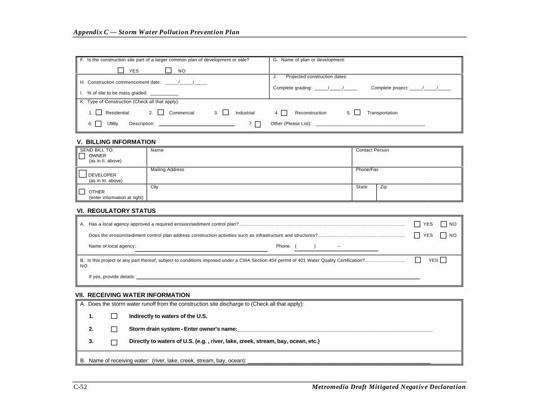
Appendix C — Storm Water Pollution Prevention Plan
C-52 Metromedia Draft Mitigated Negative Declaration
F. Is the construction site part of a larger common plan of development or sale?
YES NO
G. Name of plan or development:
H. Construction commencement date: _____/_____/_____
I. % of site to be mass graded: ___________
J. Projected construction dates:
Complete grading: _____/_____/_____ Complete project: _____/_____/_____
K. Type of Construction (Check all that apply):
1. Residential 2. Commercial 3. Industrial 4. Reconstruction 5. Transportation
6. Utility Description: 7. Other (Please List): __________________________________________
V. BILLING INFORMATIONSEND BILL TO: OWNER (as in II. above)
Name Contact Person
DEVELOPER (as in III. above)
Mailing Address Phone/Fax
OTHER (enter information at right)
City State Zip
VI. REGULATORY STATUS
A. Has a local agency approved a required erosion/sediment control plan?............................................................................................................................. YES NO
Does the erosion/sediment control plan address construction activities such as infrastructure and structures?.................................................................. YES NO
Name of local agency: Phone: ( ) --
B. Is this project or any part thereof, subject to conditions imposed under a CWA Section 404 permit of 401 Water Quality Certification?.............................. YESNO
If yes, provide details:
VII. RECEIVING WATER INFORMATIONA. Does the storm water runoff from the construction site discharge to (Check all that apply):
1. Indirectly to waters of the U.S.
2. Storm drain system - Enter owner’s name:________________________________________________________________
3. Directly to waters of U.S. (e.g. , river, lake, creek, stream, bay, ocean, etc.)
B. Name of receiving water: (river, lake, creek, stream, bay, ocean): ____________________________________________________________
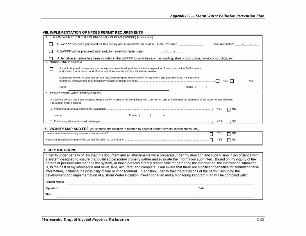
Appendix C — Storm Water Pollution Prevention Plan
Metromedia Draft Mitigated Negative Declaration C-53
VIII. IMPLEMENTATION OF NPDES PERMIT REQUIREMENTSA. STORM WATER POLLUTION PREVENTION PLAN (SWPPP) (check one)
A SWPPP has been prepared for this facility and is available for review: Date Prepared: _____/_____/_____ Date Amended: _____/_____/_____
A SWPPP will be prepared and ready for review by (enter date): _____/_____/_____
A tentative schedule has been included in the SWPPP for activities such as grading, street construction, home construction, etc.B. MONITORING PROGRAM
A monitoring and maintenance schedule has been developed that includes inspection of the construction BMPs beforeanticipated storm events and after actual storm events and is available for review.
If checked above: A qualified person has been assigned responsibility for pre-storm and post-storm BMP inspectionsto identify effectiveness and necessary repairs or design changes........................................................................................................ YES NO
Name: Phone: ( ) --
C. PERMIT COMPLIANCE RESPONSIBILITY
A qualified person has been assigned responsibility to ensure full compliance with the Permit, and to implement all elements of the Storm Water PollutionPrevention Plan including:
1. Preparing an annual compliance evaluation........................................................................................................................................... YES NO
Name: Phone: ( ) --
2. Eliminating all unauthorized discharges.................................................................................................................................................. YES NO
IX. VICINITY MAP AND FEE (must show site location in relation to nearest named streets, intersections, etc.)Have you included a vicinity map with this submittal? ...................................................................................................................................... YES NO
Have you included payment of the annual fee with this submittal?................................................................................................................... YES NO
X. CERTIFICATIONS“I certify under penalty of law that this document and all attachments were prepared under my direction and supervision in accordance witha system designed to assure that qualified personnel properly gather and evaluate the information submitted. Based on my inquiry of theperson or persons who manage the system, or those persons directly responsible for gathering the information, the information submittedis, to the best of my knowledge and belief, true, accurate, and complete. I am aware that there are significant penalties for submitting falseinformation, including the possibility of fine or imprisonment. In addition, I certify that the provisions of the permit, including thedevelopment and implementation of a Storm Water Pollution Prevention Plan and a Monitoring Program Plan will be complied with.”
Printed Name:
Signature: Date:
Title: