Appendix A4.4 Outline Construction Method Statement
43
TECHNICAL APPENDIX A4.4 BEINNEUN WINDFARM OUTLINE CONSTRUCTION METHOD STATEMENT
Transcript of Appendix A4.4 Outline Construction Method Statement

TECHNICAL APPENDIX A4.4
BEINNEUN WINDFARM OUTLINE CONSTRUCTION METHOD STATEMENT

Beinneun Windfarm
Appendix A4.4
Outline Construction Method Statement
SLR Ref: 4051161-00005
October 2011
Version: Rev 0
RidgeWind Ltd i 405-1161-00005 Beinneun Windfarm – Construction Method Statement October 2011
SLR
G:\Projects\RidgeWind\467 Beinneun\EIA\ES Chapters\Chapters\Gate Checking\Word Docs\Volume II - Tech Appendices\A4.4 Outline Construction Method Statement.doc
CONTENTS 1.0 INTRODUCTION .......................................................................................................... 1
1.1 Background ....................................................................................................... 11.2 Structure ............................................................................................................ 11.3 Overview ............................................................................................................ 1
2.0 HEALTH AND SAFETY ............................................................................................... 32.1 Introduction ....................................................................................................... 32.2 CDM Regulations .............................................................................................. 32.3 Training/Induction ............................................................................................. 3
3.0 SITE DETAILS AND PROJECT DESCRIPTION .......................................................... 43.1 Site Details ........................................................................................................ 43.2 Project Details ................................................................................................... 4
4.0 SUPERVISION ............................................................................................................. 54.1 Windfarm Construction .................................................................................... 54.2 Windfarm Decommissioning ............................................................................ 5
5.0 PHASING ..................................................................................................................... 65.1 Construction ..................................................................................................... 65.2 Reinstatement ................................................................................................... 6
6.0 PRE-CONSTRUCTION INVESTIGATION .................................................................... 76.1 Site Details ........................................................................................................ 76.2 Peat Investigation ............................................................................................. 7
7.0 CONSTRUCTION PHASE ........................................................................................... 87.1 Introduction ....................................................................................................... 87.2 Temporary Construction Compounds ............................................................. 87.3 Welfare Facilities and Services ........................................................................ 97.4 Borrow Pits/Material Supply .......................................................................... 107.5 Tree Felling ...................................................................................................... 137.6 Transport Routes ............................................................................................ 137.7 Surplus Material and Waste ........................................................................... 147.8 Dust Mitigation ................................................................................................ 167.9 Site Lighting .................................................................................................... 177.10 Vehicle Storage ............................................................................................... 187.11 Fuel and Cement Storage ............................................................................... 187.12 Spillage ............................................................................................................ 197.13 Other Storage .................................................................................................. 197.14 Prevention of Mud and Debris on Public Roads ........................................... 197.15 Water Quality Monitoring and Contingency Plans ....................................... 19
8.0 PERMANENT WORKS .............................................................................................. 228.1 Introduction ..................................................................................................... 228.2 Turbine Foundations ...................................................................................... 258.3 Crane Pads ...................................................................................................... 278.4 Control Building and Sub-Station .................................................................. 288.5 Cable Laying ................................................................................................... 288.6 Peat and Soil Storage ..................................................................................... 298.7 Water Crossings ............................................................................................. 30
9.0 OPERATIONAL PHASE ............................................................................................ 349.1 Reinstatement and Monitoring ....................................................................... 34
10.0 DECOMMISSIONING AND REINSTATEMENT ......................................................... 3510.1 Site Details ...................................................................................................... 35
11.0 REFERENCE DOCUMENTS ..................................................................................... 3612.0 CLOSURE ......................................................... ERROR! BOOKMARK NOT DEFINED.

RidgeWind Ltd ii 405-1161-00005 Beinneun Windfarm – Construction Method Statement October 2011
SLR
G:\Projects\RidgeWind\467 Beinneun\EIA\ES Chapters\Chapters\Gate Checking\Word Docs\Volume II - Tech Appendices\A4.4 Outline Construction Method Statement.doc
TABLES Table 7-1 - Common Construction Wastes………………………………………………...16 Table 7-2 - Dust Mitigation Measures……………………………………………………….18 Table 7-3 - Proposed Surface Water Monitoring………………………………………….21

RidgeWind Ltd 1 405-1161-00005 Beinneun Windfarm – Construction Method Statement October 2011
SLR
1.0 INTRODUCTION
1.1 Background
This document is the draft Construction Method Statement (CMS) for the proposed windfarm development at Beinneun (“the Development”).
This CMS has been prepared to take account of “Good Practice During Wind Farm Construction”1
As noted in reference 1, this is a fluid document that will evolve during the different phases of the project. As such it will be subject to constant review to address:
(as well as other relevant guidance) and provides the construction activities methodology pertinent to the Environmental Statement (ES).
• Any planning conditions; • Unforeseen conditions encountered during construction; • Changes in best practice during the life of the windfarm; and • Changes resulting from the construction methods used by the contractor(s).
This is a standalone document that will be maintained and updated on site, and will be augmented by associated design specifications and Construction (Design and Management) documentation such as the Principal Contractors Construction Phase Plan.
1.2 Structure
The structure of this CMS reflects the different phases of the life of the Development together with other key information, namely:
• Health and Safety (Section 2); • Site Details and Project Description (Section 3); • Supervision (Section 4); • Phasing (Section 5); • Pre-construction Investigations (Section 6); • Construction Phase (Section 7); • Permanent Works (Section 8); • Operational Phase (Section 9); • Decommissioning and Restoration (Section 10); and • Reference Documents (Section 11).
It should be noted that reference to permanent works above refers to the life of the Development only.
1.3 Overview
This document provides information on the construction methods which are to be adopted to mitigate the environmental impact of the construction of the Development.
The principal objective of this document is to provide information on the proposed infrastructure and to aid in avoiding, minimising and controlling adverse environmental impacts associated with the construction of the Development. Furthermore, this document
1 Good Practice During Windfarm Construction, Version 1, October 2010.

RidgeWind Ltd 2 405-1161-00005 Beinneun Windfarm – Construction Method Statement October 2011
SLR
aims to define good practice as well as specific actions required to implement mitigation requirements as identified in the Environmental Statement (ES), the planning process and/or other licensing or consenting processes.
While this version of the document provides an outline of methods to be adopted, where avoidance or further minimisation of risks to the environment can be demonstrated through use of alternative methods or improvements to current practices, the Contractor will implement these wherever possible.
The methods and principles contained herein, as well as within referenced legislative instruments and published guidance documents, will be adhered to by the appointed Contractor in developing the detailed design of the Development and in development of detailed construction method statements and other plans relating to environmental management as required by the Contract.
This document should be read and implemented on site in conjunction with the requirements of the following primary documents:
• Engineering in the Water Environment, Good Practice Guide, Construction of River Crossings2
• Prevention of Pollution from Civil Engineering Contracts: Special Requirements, (WAT-SG-25);
3
• Prevention of Pollution from Civil Engineering Contracts: Guidelines for the Special Requirements
;
4
Additionally, all works shall take account of the requirements of the reference documents presented in Section 11.
.
2 Engineering in the Water Environment, Good Practice Guide, Construction of River Crossings2, First Edition, SEPA, April 2008 (WAT-SG-25). 3 Prevention of Pollution from Civil Engineering Contracts: Special Requirements3 Version 2, SEPA, June 2006. 4 Prevention of Pollution from Civil Engineering Contracts: Guidelines for the Special Requirements, Version 2, SEPA, June 2006.

RidgeWind Ltd 3 405-1161-00005 Beinneun Windfarm – Construction Method Statement October 2011
SLR
2.0 HEALTH AND SAFETY
2.1 Introduction
The construction works shall be undertaken in accordance with primary health and safety legislation, namely:
• Health and Safety at Work Act 1974; and • Construction (Design and Management) Regulations (2007).
In addition the project should be undertaken in accordance with secondary legislation such as the Lifting Regulations (LOLER).
2.2 CDM Regulations
The Principal Contractor will provide a Construction Phase Plan in accordance with the CDM regulations. This plan shall include (but not be limited to) a construction programme, emergency procedures, site layouts and fire plans, method statements and details of the proposed induction programme. This induction programme will include both the Principal Contractor’s site specific rules as well as the Client’s requirements, and will include instructions to all staff regarding the Emergency Pollution Prevention Plan (EPPP) and relevant procedures.
2.3 Training/Induction
An induction will be required for all workers (permanent / temporary / contractor / subcontractor), site visitors, client representatives or other 3rd parties. Inductions shall be documented.
Plant operators and construction staff will be trained by the Principal Contractor with regard to spill prevention/mitigation measures and procedures and in the use of relevant mitigation material (e.g. spill kits).
RidgeWind Ltd 4 405-1161-00005 Beinneun Windfarm – Construction Method Statement October 2011
SLR
3.0 SITE DETAILS AND PROJECT DESCRIPTION
3.1 Site Details
The following is a summary of the site setting and access locations:
• Site is bounded to the west by the A87 road, moorland and Loch Loyne; • Site is bounded to the north by the A887 road, moorland and Beinneun Forest; • Site is bounded to the south by moorland; • Site is bounded to the east by moorland; • There are several small water courses on the site; • There are several small lochs and lochans on the site; • There is an existing access track running southwards in the northern part of the site; • The main access to the site will be via the A887, with a ‘4x4’ access off the A87.
3.2 Project Details
In summary the project will consist of the following:
• New tracks consisting of the following: • 18.9 km of new track of which, 2 km will be the 4x4 access track; • 1.9 km of upgraded estate track; • 0.5km of potential track (between Turbines 5 and 7); • Two temporary construction compounds (100 m x 80 m) which shall include laydown
areas to be used as follows:
o A temporary construction compound adjacent to the main entrance (near A887). This will facilitate control of access to the site during construction and reception of stores and materials. This will also be the main construction compound whilst the access road to the site is being constructed (to be reinstated after construction);
o A second temporary construction compound located between turbines 10 and 11 and will be a hardstanding area to manage stores and plant more local to the turbine locations (to be reinstated after construction).
• Three on-site borrow pits are proposed (to be reinstated after construction). One of the borrow pits to be used for batching of concrete should a suitable source of aggregate be discovered on site;
• 25 turbines of up to 3.4 MW with a maximum height to blade tip 132m; • Crane hardstanding areas at each turbine, approximately 40m x 28m; • Under-ground cables (approx. 20 km) between all turbines and the substation; • A single anemometer mast, 80 m height; • A sub-station (33 kVA) compound measuring 100m x 60m adjacent to the main
entrance (near the A887). This will include the control building, the sub-station, transformers and the DVAR equipment. The Control Building will be typically (19m x 8m x 3.5m);
• Laydown areas will typically be co-located with construction compounds and will make use of crane hardstandings as laydown areas;
• 16No. new Water Crossing points including 1No. bridge crossing between Turbines 17 and 18, and 4No. upgraded existing water crossing points;; and
• Transformers at each turbine location measuring approximately 2m x 2m on a concrete plinth and 3 m high. These will be located adjacent to the turbine bases.

RidgeWind Ltd 5 405-1161-00005 Beinneun Windfarm – Construction Method Statement October 2011
4.0 SUPERVISION
4.1 Windfarm Construction
The Client will appoint an Ecological/Environmental Clerk of Works (ECoW) on a full-time basis during the period of windfarm construction together with post–construction restoration. The appointment of the ECoW will be approved by Highland Council.
The purpose of the ECoW is to provide environmental advice and monitor compliance. The ECoW shall ensure that biodiversity is secured and impacts either avoided or minimised.
The ECoW will have sufficient powers to:
• Oversee and identify any actions required; • Authorise temporary stoppage of works if required; and • To ensure that satisfactory construction arrangements and mitigation measures are
in place.
The ECoW shall undertake the following activities:
• Monitoring the effects of construction activities before, during and after construction; • Monitoring pollution prevention and migration; • Protection of breeding birds; • Protection of other species; • Maintain an environmental register; • Report to the local authority on a monthly basis; and • Undertake environmental inductions to contractor(s)’s staff.
It is proposed that the ECoW will also carry out or supervise the monitoring programmes described in Sections 7.15 and 9.1.
4.2 Windfarm Decommissioning
It is likely that the developer shall employ an ECoW for the decommissioning and restoration activities. However, as the nature of the work will be slightly different, the exact activities would be agreed nearer to the time of decommissioning.

RidgeWind Ltd 6 405-1161-00005 Beinneun Windfarm – Construction Method Statement October 2011
5.0 PHASING
5.1 Construction
The construction works are expected to be completed over a period of 25 months, which includes a total of 8 months anticipated ‘down time’ during two winter periods.
The following phasing concepts will be taken into consideration for the construction works:
• Construction activities may have potential to disturb breeding birds, or it may not be possible to schedule all disturbing works to occur outside the breeding season. Where this is the case, construction activities will aim to be started outside the breeding season, but may run into the breeding season. Birds returning to the area to breed will then have the opportunity to choose nest-sites away from potentially disturbing activities that are already in operation. Commencement of activities with potential to disturb birds will not take place within the breeding season, if feasible.
Additionally a detailed construction programme will be provided as part of the final CMS and the Pre-Construction Information.
5.2 Reinstatement
The following phasing concepts will be taken into consideration for the reinstatement works:
• Peat/Cover soils replacement of disturbed areas that do not form part of the permanent works;
• Heather seed collection to be undertaken between months of January to March (weather permitting); and
• Reinstatement by re-seeding not during months of frost (January – March/April) or drought (July/August).

RidgeWind Ltd 7 405-1161-00005 Beinneun Windfarm – Construction Method Statement October 2011
6.0 PRE-CONSTRUCTION INVESTIGATION
6.1 Site Details
Pertinent investigation details appropriate to this CMS are:
• Peat Investigation (Appendix A9.1 of this ES); • Hydrology Assessment (Chapter 9 of this ES); and • Ecological Assessment (Chapter 7 of this ES).
6.2 Peat Investigation
An intrusive investigation of peat thickness was undertaken by SLR which is contained within Appendix A9.1 of this ES.
In general, the northern and eastern area of the site has very little peat cover and is typically 0.7 m thick.
The south and south-west area of the site (referred to as Areas 1 and 2 in A9.1) does have thicker areas of peat which can typically be up to 2.7 m thick.
There is negligible thickness of peat at all the turbine locations. Current knowledge of peat depths in Area 1 indicates that the access track will not require to be of a floating road design. However, should areas be identified at the detailed design stage where sufficient lengths of track are required to cross areas of peat of >1 m depth, then a floating road will be used. 6.3 Hydrology Study A site walkover and study has concluded that 16 No. new water crossings will be required and 4 No. upgrades to existing water crossings are required at the site. One of these new water crossings shall include a bridging solution to gap a stream in a location between Turbines 17 and 18. A watercourse crossing inventory is presented in Appendix A9.2 in this ES.

RidgeWind Ltd 8 405-1161-00005 Beinneun Windfarm – Construction Method Statement October 2011
7.0 CONSTRUCTION PHASE
7.1 Introduction
This chapter describes in more detail the key components of construction and the impact they are likely to have on the environment.
7.2 Temporary Construction Compounds
Two temporary construction compounds (TCC) are proposed for this development during the construction phase. These will both measure 100 m x 80 m, with one located close to the site entrance (TCC1) and the other between Turbines 10 and 11 (TCC2).
TCC1 is located adjacent to the site entrance will serve as the main compound until the second compound is constructed. During this time, TCC1 will include the following:
• Temporary Portakabin type structures to be used for site offices, the monitoring of incoming vehicles and welfare facilities including toilets with provision for sealed waste storage and removal;
• Parking for construction staff, visitors and construction vehicles; • Secure storage for tools and small parts; • Fuelling point, or mobile fuel bowser to comply with SEPA PPG 7 (The safe operation
of refuelling facilities, July 2011), and PPG 2 (Above ground oil storage tanks, August 2011);
• A tool store and workshop (lockable containers) for workers/subcontractors, situated at a location to be agreed with the Principal Contractor. These tool stores will provide a safe and sheltered working area for maintenance and repair work. A welder, hydraulic pipe fitting crimper and all ancillary equipment will be available in the tool stores; and
• A reception area for incoming vehicles and staff.
Once TCC2 has been prepared and established, then TCC1 will then be used for and include the following:
• Temporary Portakabin type structures to be used for site offices, the monitoring of incoming vehicles and welfare facilities including toilets with provision for sealed waste storage and removal; and
• A lay-down area for materials and components arriving on site.
TCC2 will be located between Turbines 10 and 11. Once this has been established, this compound will take over as the main contractor’s compound, and will include the following:
• Temporary Portakabin type structures (delivered on flat bed lorries) to be used for site offices, the monitoring of incoming vehicles and welfare facilities including toilets with provision for sealed waste storage and removal;
• Parking for construction staff, visitors and construction vehicles; • Secure storage for tools and small parts; • Fueling point, or mobile fuel bowser to comply with SEPA PPG 7 (The safe
operation of refuelling facilities, July 2011), and PPG 2 (Above ground oil storage tanks, August 2011); and
• A tool store and workshop (lockable containers) for workers/subcontractors, situated at a location to be agreed with the Principal Contractor. These tool stores will provide

RidgeWind Ltd 9 405-1161-00005 Beinneun Windfarm – Construction Method Statement October 2011
a safe and sheltered working area for maintenance and repair work. A welder, hydraulic pipe fitting crimper and all ancillary equipment will be available in the tool stores.
The design and location of site offices and facilities layout will consider the orientation of the cabins to take into account the best use of sunlight in order to reduce electricity consumption. Where and when compound lighting is required it will be designed to minimise light pollution to the surrounding area. All lights will face inwards.
Both TCCs would also be used as a storage compound for various components, fuels and materials required for construction.
All areas of the site including accommodation areas shall be kept clean and tidy with a regime of good housekeeping established to facilitate mobility of personnel and plant/equipment around the site and eliminate potential hazards and environmental pollution.
Both areas would be sited to use flatter ground. The compound area will be built by stripping heather/peat/topsoil and regrading, then laying geotextile and a crushed rock layer. For TCC1 this will be imported stone, and for TCC2 this will be site won rock. All crushed rock used will have a fines content of less than 20% to reduce the risk of sediment contamination.
The stripped heather/peat/topsoil will be stored adjacent to the compounds in a linear bund typically no greater than 2 m in elevation for future restoration purposes.
It is proposed that un-contaminated surface run-off from the TCCs is accommodated in a shallow swale or soakaway which will be constructed as a perimeter ditch to avoid contamination of watercourses should there be a spillage. All other run-off from the site will follow natural drainage patterns and newly installed drainage routes.
The compound and lay-down areas will be reinstated at the end of the construction period. Reinstatement will involve removal of the imported material and underlying geotextile. The exposed substrate will be gently ripped and the stored subsoil and topsoil replaced. The surface will be re-seeded as required using the same seed mix as that used for the reinstatement of track verges and batter (in consultation with SNH). Figure 4.10 of the ES provides an indicative layout of a construction compound.
7.3 Welfare Facilities and Services
Welfare facilities will be provided for the duration of the construction period in accordance with the Construction (Design and Management) Regulations 2007 including sanitary conveniences, washing facilities, drinking water, changing rooms and accommodation for clothing not worn during working hours and rest facilities.
Toilets during the construction phase will be chemical toilets or a mobile toilet unit. The waste will be emptied on a regular basis by a registered waste disposal contractor. Toilets will be located within the temporary construction compound areas.
Potable water will be supplied via a bowser and/or bottled water. The water will be used for messing purposes during the construction phase. Any water stored on site shall be stored and monitored to ensure it is fit as a potable supply.
If additional water is required to be abstracted from site water bodies for site based activities (i.e. dust suppression, etc), the CAR Regulations apply and advice will be sought from SEPA

RidgeWind Ltd 10 405-1161-00005 Beinneun Windfarm – Construction Method Statement October 2011
prior to any abstraction. Alternatively additional water can be provided from a rain water collector.
All electrical equipment and its installation and maintenance will be undertaken by a qualified and competent person.
7.4 Borrow Pits/Material Supply
7.4.1 General
In order to construct the access tracks, passing places, and formation of new hardstanding areas such as crane pads, site construction compounds and lay down areas, crushed rock is required. It is proposed to source this material from on-site borrow pits, to reduce the need to import materials. In addition, and where suitable, some rock types may be utilised as a source of aggregate for concrete batching for the turbine foundations.
Three borrow pits are proposed as part of this project. Two of the borrow pits are located along the proposed route through the Beinneun Forrest and the third is located between Turbines 11 and 16.
In general, the borrow pit areas will be stripped back of heather/peat/topsoil which will be stored adjacent to the respective borrow pit site for future reinstatement.
The rock will be extracted using recognised quarrying techniques and crushed to provide the required material grade. The rock extraction method will vary and will be dependent upon the nature of the material encountered, depth of weathering and level of fracturing. A combination of digging, ripping and blasting shall be utilised, followed by crushing, as appropriate.
The borrow pit works will be subject to significant health, safety and environmental constraints, including:
• Segregation and fencing off of processing plant with only authorised personnel permitted to enter. These works will be carried out on a level working platform;
• Bunding and fencing of borrow pit high wall to prevent plant / personnel falling into the void;
• Surface water / drainage mitigation to prevent pollution, silt run off and inundation into the void;
• Exclusion zones implemented during blasting works; and • Fitting of spray bars to the processing plant to keep dust down during dry / windy
periods.
7.4.2 Borrow Pit Establishment
Prior to any borrow pit works beginning at each location is shall be surveyed and the required area pegged out.
Once the extent of the borrow pit will be established a temporary Heras type fence shall be erected to this boundary with appropriate warning signs. All fencing and warning signs will be checked on a regular basis and repaired/replaced as necessary.
Once a proposed borrow pit location has been surveyed and pegged-out, the Ecological Clerk of Works (ECoW) and Archaeological Clerk of Works (ACoW), if appointed, shall be
RidgeWind Ltd 11 405-1161-00005 Beinneun Windfarm – Construction Method Statement October 2011
consulted prior to any further development of the location. Once the ECoW and ACoW have given their approval for the demarked location, borrow pit preparation may commence.
7.4.3 Borrow Pit Preparation
Surface vegetation/peat shall be cut and placed to one-side. This material shall be retained for reinstatement purposes once the borrow pit workings are completed.
The removal of the existing superficial soil materials (“overburden”) would typically be undertaken using a combination of crawler tractor dozers and backacters with the material loaded by mechanical loading shovel onto 30 tonne articulated dump trucks and transported to designated stockpile locations adjacent to the worked area and retained for restoration purposes. Where different overburden materials are present these will be stored according to type. Overburden shall be stockpiled carefully, with consideration given to slope gradient, proximity to watercourses or other sensitive receptors, and shall avoid loading areas of deeper (>1 m deep) for peat and <2 m for other soils. This excavated overburden will be lightly tracked to seal the windrows to prevent erosion.
Care will be taken not to traffic undisturbed soils unnecessarily and to limit the working area as far as possible to avoid unnecessary ground excavation and disturbance.
The borrow pit may require a hardstanding to be created (within its footprint) in order to provide an initial working platform, whether this is for storage of plant and vehicles or for direct access to the working face. This area will also serve as an initial platform for setting up any crushing equipment deemed necessary for the removal and preparation of rock material.
7.4.4 Borrow Pit Working
Following the exposure of the rock head, the material will be dealt with either by digging, ripping or blasting, or a combination of techniques. A combined approach may be required due to variability in the strength and integrity of the rock within individual pits and from pit to pit.
A maximum of 5 m high benches would be worked in accordance with standard construction practice. Where the rock is prohibitively resistant to allow digging or ripping, blasting will be undertaken. This would be controlled by a competent and qualified shot firer and will ensure that good blasting practice is adopted. The blasting will also be in compliance with the relevant health and safety regulations (The Quarries Regulations 1999) and other relevant provisions.
The blasted rock will subsequently be ripped/dug as required and treated as described above. Blasting operations will be kept to an absolute minimum and only utilised where in situ rock material cannot feasibly be removed by mechanical equipment.
Mobile crushing and screening plant will be established within each borrow pit and all crushing and grading and stockpiling of material will take place within the confines of the identified borrow pits.
As the borrow pit progresses, then any crushing and processing plant can be moved further into the borrow pit area to mitigate noise and visual impact.
RidgeWind Ltd 12 405-1161-00005 Beinneun Windfarm – Construction Method Statement October 2011
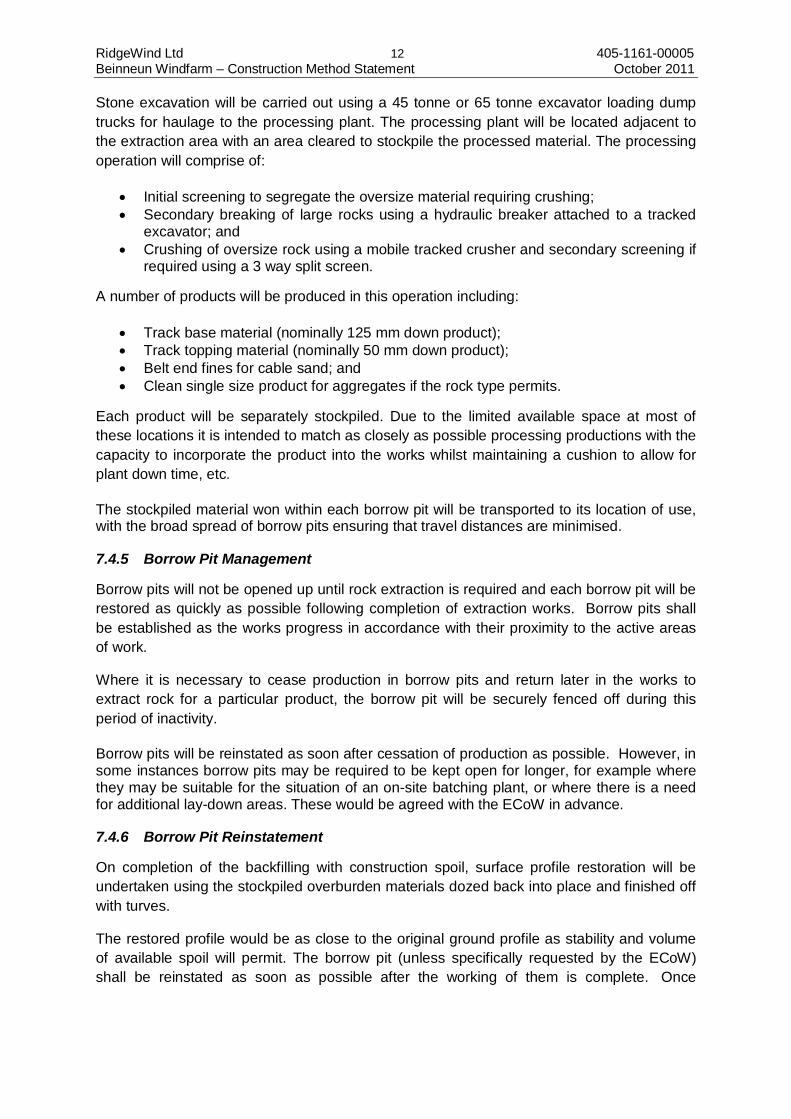
Stone excavation will be carried out using a 45 tonne or 65 tonne excavator loading dump trucks for haulage to the processing plant. The processing plant will be located adjacent to the extraction area with an area cleared to stockpile the processed material. The processing operation will comprise of:
• Initial screening to segregate the oversize material requiring crushing; • Secondary breaking of large rocks using a hydraulic breaker attached to a tracked
excavator; and • Crushing of oversize rock using a mobile tracked crusher and secondary screening if
required using a 3 way split screen.
A number of products will be produced in this operation including:
• Track base material (nominally 125 mm down product); • Track topping material (nominally 50 mm down product); • Belt end fines for cable sand; and • Clean single size product for aggregates if the rock type permits.
Each product will be separately stockpiled. Due to the limited available space at most of these locations it is intended to match as closely as possible processing productions with the capacity to incorporate the product into the works whilst maintaining a cushion to allow for plant down time, etc.
The stockpiled material won within each borrow pit will be transported to its location of use, with the broad spread of borrow pits ensuring that travel distances are minimised.
7.4.5 Borrow Pit Management
Borrow pits will not be opened up until rock extraction is required and each borrow pit will be restored as quickly as possible following completion of extraction works. Borrow pits shall be established as the works progress in accordance with their proximity to the active areas of work.
Where it is necessary to cease production in borrow pits and return later in the works to extract rock for a particular product, the borrow pit will be securely fenced off during this period of inactivity.
Borrow pits will be reinstated as soon after cessation of production as possible. However, in some instances borrow pits may be required to be kept open for longer, for example where they may be suitable for the situation of an on-site batching plant, or where there is a need for additional lay-down areas. These would be agreed with the ECoW in advance.
7.4.6 Borrow Pit Reinstatement
On completion of the backfilling with construction spoil, surface profile restoration will be undertaken using the stockpiled overburden materials dozed back into place and finished off with turves.
The restored profile would be as close to the original ground profile as stability and volume of available spoil will permit. The borrow pit (unless specifically requested by the ECoW) shall be reinstated as soon as possible after the working of them is complete. Once
RidgeWind Ltd 13 405-1161-00005 Beinneun Windfarm – Construction Method Statement October 2011
reinstated the borrow pit shall be inspected periodically to monitor for any settlement or surface erosion that may occur, or deterioration of the surface vegetation.
All borrow pits (unless specifically requested by the ECoW) shall be reinstated as soon as possible after the working of them is complete. Once reinstated a borrow pit shall be inspected periodically to monitor for any settlement or surface erosion that may occur, or deterioration of the surface vegetation.
Consideration shall be given to the need for watering a restored area during prolonged dry periods, to encourage re-establishment of vegetation. Should the ECoW identify any unacceptable degradation to a reinstated borrow pit then further restoration management techniques shall be considered, including re-profiling of the surface or reseeding of vegetation, as appropriate.
Following completion of extraction each borrow pit will be reinstated. Reinstatement can be minimal, partial or complete.
For complete reinstatement (i.e. restoration), the borrow pit void would be in-filled with excavated materials won from other site activities, and finished off with overburden spoil side-cast from the location when the borrow pit was developed. In-fill materials would be compacted in layers to leave a smooth profile. This would then be lightly cultivated and turfed over with the topsoil/turves cut from the location. Borrow Pits in forest areas may be re-planted where possible.
For partial reinstatement, this is where, due to lack of volume of available spoil, the original ground profile is not achieved. Reinstatement techniques would be similar to those described above for “restoration”, with compaction of layers. The final surface profile will be sympathetically landscaped to the surrounding topography under the direction of the ECoW.
Minimal reinstatement may occur where the excavation is left open, typically as part of a new habitat creation for wildlife, particularly birds, with either a flooded excavation floor, to encourage waders, or steep rear scarp to encourage raptors. Minimal reinstatement is only ever proposed in limited situations, and would only be provided where the ECoW instructed this.
7.5 Tree Felling
Tree felling operations will be limited to the wooded areas within the site. Tree felling will be undertaken by a tree felling contractor and their subcontractors (if applicable).
Prior to the commencement of felling work, all Forestry Authority felling licences or equivalent shall be obtained by the tree felling contractor and a detailed site specific Health & Safety and Environmental risk assessment will be completed by the tree felling contractor.
The works will be undertaken in accordance with the principal reference document, the Forest and Water Guidelines (See Appendix A4.1). Where applicable all forest operations will comply with UK Forestry Standards.
7.6 Transport Routes
The site access is direct from the A887. A Traffic Management Plan (TMP) will be developed following appointment of the principal contractor and identification of the material supply points and included in the final CMS.

RidgeWind Ltd 14 405-1161-00005 Beinneun Windfarm – Construction Method Statement October 2011
Turbine components will be delivered to site either from the Kyle of Lochalsh, Invergordon, or from other ports and then utilising motorways and trunk roads.
The timing of deliveries of abnormal loads will be agreed in consultation with Highland Council, the local police and Transport Scotland.
Once planning permission has been received and prior to construction, the route shall be further inspected by suitable engineers, in conjunction with the police and the relevant highway authorities, with a view to finalising the TMP and to obtaining a suitable licence for the movement of abnormal loads.
The TMP will include:
• Delivery schedule to ensure impacts on the road network are minimised;
• Liaison with the port over sea delivery schedules and provision of lay down areas as required;
• Detailed design of temporary road improvements; and
• Assessment of existing street furniture and bridge classifications and preparation of a schedule of temporary works along the access route.
7.7 Surplus Material and Waste
7.7.1 Introduction
The Site Waste Management Plan (SWMP) Regulations 2008 came into force in April 2008. Although these regulations only apply to England, the principle of SWMP are recommended as good practice within the construction industry, and as such are recommended to be adopted in this project.
The SWMP will detail how all waste materials will be managed, including the management and definition of excavated materials.
The Principal Contractor will take all reasonable steps to ensure that all waste from the site is dealt with in accordance with the requirements under the Environmental Protection (Duty of Care) Regulations 1991 (and amendments) and that materials will be handled efficiently and waste managed appropriately.
Appropriate waste management, disposal and waste carrier documentation and licences will be obtained (e.g. complete waste transfer notes prior to waste leaving site, ensure all waste carriers have a valid waste carrier’s registration certificate, ensure wastes are disposed of at a correctly licensed site, complete notification for hazardous waste to SEPA).
Surplus materials will include materials generated by the excavation/extraction works during construction of roads, lay down compounds and turbine foundations, mainly comprising excavated excess peat and sub-soils.
Waste streams will include wastes generated by plant, machinery and construction workers over the period of the works, for example waste oils, sewage, refuse (paper, carton, plastic etc), wooden pallets, waste batteries, fluorescent tubes etc.
RidgeWind Ltd 15 405-1161-00005 Beinneun Windfarm – Construction Method Statement October 2011
7.7.2 Soils and Spoil
It is planned that any materials excavated on site in the course of the construction works (i.e. soil/peat stripping for road construction, turbine foundations) will be stored on site and re-used as described in Section 8.8. As such, off-site disposal of this material is not anticipated.
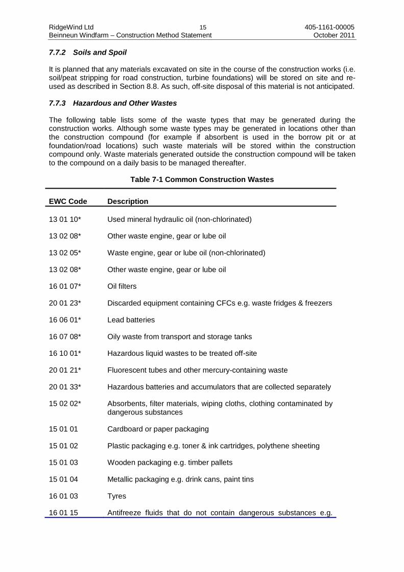
7.7.3 Hazardous and Other Wastes
The following table lists some of the waste types that may be generated during the construction works. Although some waste types may be generated in locations other than the construction compound (for example if absorbent is used in the borrow pit or at foundation/road locations) such waste materials will be stored within the construction compound only. Waste materials generated outside the construction compound will be taken to the compound on a daily basis to be managed thereafter.
Table 7-1 Common Construction Wastes
EWC Code Description
13 01 10* Used mineral hydraulic oil (non-chlorinated)
13 02 08* Other waste engine, gear or lube oil
13 02 05* Waste engine, gear or lube oil (non-chlorinated)
13 02 08* Other waste engine, gear or lube oil
16 01 07* Oil filters
20 01 23* Discarded equipment containing CFCs e.g. waste fridges & freezers
16 06 01* Lead batteries
16 07 08* Oily waste from transport and storage tanks
16 10 01* Hazardous liquid wastes to be treated off-site
20 01 21* Fluorescent tubes and other mercury-containing waste
20 01 33* Hazardous batteries and accumulators that are collected separately
15 02 02* Absorbents, filter materials, wiping cloths, clothing contaminated by dangerous substances
15 01 01 Cardboard or paper packaging
15 01 02 Plastic packaging e.g. toner & ink cartridges, polythene sheeting
15 01 03 Wooden packaging e.g. timber pallets
15 01 04 Metallic packaging e.g. drink cans, paint tins
16 01 03 Tyres
16 01 15 Antifreeze fluids that do not contain dangerous substances e.g.
RidgeWind Ltd 16 405-1161-00005 Beinneun Windfarm – Construction Method Statement October 2011
EWC Code Description Coolants
16 01 17 Ferrous metal from vehicles e.g. car parts
16 02 14 Non hazardous waste electricals e.g. power tools
16 05 05 Gases in pressure containers i.e. gas cylinders
17 01 01 Concrete
17 02 01 Wood from construction or demolition e.g. timber trusses, supports, frames, doors
17 04 11 Cables that do not contain dangerous substances e.g. electric cabling
20 01 01 Paper & card similar to that from households e.g. office paper, junk mail
20 01 30 Non hazardous detergent e.g. flushing agent/universal cleaner
20 01 39 Separately collected plastics e.g. plastic containers, bottles
20 03 01 Mixed waste similar to that from households e.g. mixed office, kitchen & general waste
20 03 04 Septic tank sludge
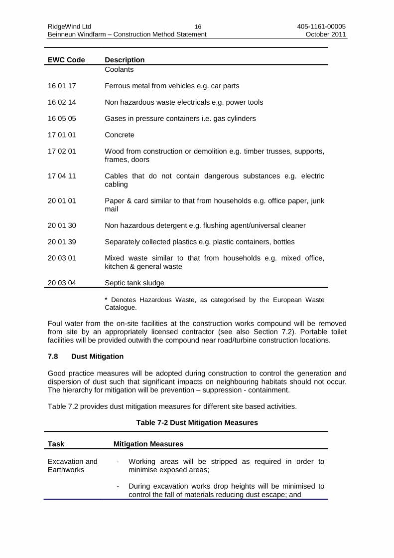
* Denotes Hazardous Waste, as categorised by the European Waste Catalogue.
Foul water from the on-site facilities at the construction works compound will be removed from site by an appropriately licensed contractor (see also Section 7.2). Portable toilet facilities will be provided outwith the compound near road/turbine construction locations.
7.8 Dust Mitigation Good practice measures will be adopted during construction to control the generation and dispersion of dust such that significant impacts on neighbouring habitats should not occur. The hierarchy for mitigation will be prevention – suppression - containment.
Table 7.2 provides dust mitigation measures for different site based activities.
Table 7-2 Dust Mitigation Measures
Task Mitigation Measures
Excavation and Earthworks
- Working areas will be stripped as required in order to minimise exposed areas;
- During excavation works drop heights will be minimised to control the fall of materials reducing dust escape; and

RidgeWind Ltd 17 405-1161-00005 Beinneun Windfarm – Construction Method Statement October 2011
Task Mitigation Measures
- Temporary cover may be provided for earthworks if necessary, and completed earthworks and other exposed areas will be covered with topsoil and re-vegetated as soon as it is practical in order to stabilise surfaces.
Stockpiling of loose materials
- Ensure that stockpiles exist for the shortest possible time;
- Material stockpiles will be low mounds without steep sides or sharp changes in shape;
- Wherever possible, stockpiles will be kept securely sheeted;
- Material stockpiles will be located from the site boundary, sensitive receptors, watercourses and surface drains;
- Material stockpiles will be sited to account for the predominant wind direction and the location of sensitive receptors; and
- Any long term stockpiles will be seeded or turfed to stabilise surfaces.
Roadworks/ traffic movements
- Water bowsers will be available on site and utilised for dust suppression during roadworks/ vehicle movements when and where required;
- Daily visual inspections will be undertaken to assess need for use of water bowsers; and
- Daily visual inspections will be undertaken to assess the condition of the junction of the site track with the A887 and its approaches.
7.9 Site Lighting
Temporary site lighting may be occasionally required for specific activities to ensure safe working conditions, but will be carried out within the limits of the permissible working hours. It is intended the type of lighting would be non-intrusive and specifically designed to negate or minimise any affect to local properties.
7.9.1 Lighting during construction phase
Given the proposed size and scope of the Development, it is most likely that the construction timetable will require elements of the works to be undertaken during periods of the year when natural daylight is limited.
The use of artificial lighting may therefore be required in order to facilitate the works, such as vehicle and plant headlights; compound lighting; office complex lighting; and localised floodlights/mobile lighting units. There will be fewer requirements for artificial lighting in the summer months when natural lighting will be present during normal working hours. It is not
RidgeWind Ltd 18 405-1161-00005 Beinneun Windfarm – Construction Method Statement October 2011
known of any issues with regards to the limit of lighting levels in this area, but lighting will be provided to meet the required lighting levels for the respective works which are being undertaken, especially where there is plant and machinery involved. Any issues identified with regards to limiting the lighting levels, either the lux values, or the time/duration of the lighting will be taken into consideration as part of the developed construction method statement.
7.9.2 Permanent Lighting
Lighting requirements for the operational phase would be limited to internal lighting to turbines, the control building and sub-station which can all generally be controlled to have minimal impact. External lighting will be restricted to emergency and security lighting at the compound and sub-station, and would not be a source which is regularly used. It is not proposed to use street lighting either internally on site tracks, or at the junction with the public highway.
7.9.3 Decommissioning
Decommissioning of the facility would be subject to similar lighting as described for the construction phase, but is likely to be easier to restrict, as this would take less time, could be phased, and undertaken during periods of greater natural daylight.
7.10 Vehicle Storage
Appropriate areas will be provided adjacent to or within the site compounds to allow staff and visitor vehicles to be parked. In addition, appropriate provision will be made for the layover of HGV traffic e.g. concrete trucks to ensure that the adjacent road remains clear and available for use at all times. The track design incorporates lay-downs and crane pads which from time to time may be required to temporarily store vehicles i.e. as waiting areas.
7.11 Fuel and Cement Storage
Generally, re-fuelling of mobile plant and machinery will be carried out at a designated location within the site compound only.
Vehicle re-fuelling will take place within the compound at a dedicated impermeable refuelling pad. The pad will be bunded and equipped with a collection sump. Refuelling will be carried out using an approved mobile fuel bowser with a suitable pump and hose. Absorbent material (spill kits) will be available on site and will be deployed to contain drips and small spillages. All other fuels, oils and potential contaminants, as well as waste oils, will be stored within the site compound in secure, fit for purpose containers within bunded containment as appropriate and in accordance with SEPA guidance (PPG 2: Above ground oil storage tanks, August 2011). The bunded containment shall have a capacity of 110% of the volume to be stored and shall have impervious, secured walls and base.
Maintenance of mobile plant will take place within the construction compound only and shall comply with SEPA PPG 7 (The safe operation of refuelling facilities, July 2011).
There shall be no fuel storage outside the compound. Plant shall be maintained in good operational order and any fuel/oil leaks recorded for attention. Absorbent pads/granules in the case of an accidental leak/spillage shall be available at the borrow pit.
RidgeWind Ltd 19 405-1161-00005 Beinneun Windfarm – Construction Method Statement October 2011
7.12 Spillage
Spillage of fuel, oil and chemicals will be minimised by implementation of an Emergency Pollution Prevention Plan (EPPP) which will be prepared by the Principal Contractor. In the event of any spillage or pollution of any watercourse the emergency spill procedures as described in the EPPP shall be implemented immediately.
7.13 Other Storage
Track stone material stockpiles will generally be limited to the compound or within work areas. This material will be transported and deposited directly to the point of use from the compound. Therefore track stone will generally not be stockpiled around the site.
Stripped topsoil/subsoil will be stockpiled in a suitable location away from the area of movement of heavy vehicles, machinery and equipment, to minimise compaction of soil. Stockpiling of excavated material shall be managed such that the potential contamination of down slope water supplies and/or natural drainage systems is mitigated/minimised.
Low mound stockpiles will be formed from excavated material, adjacent to access tracks, turbine areas and compound areas, away from open drains.
Waste storage and raw material will be at the construction works compounds as detailed in Section 7.7.
7.14 Prevention of Mud and Debris on Public Roads
Plant and wheel washing facilities and road sweepers shall be provided as required to prevent mud and deposits from being transferred from site onto the public highway.
Plant and wheel washing, where provided, shall be located within a designated area of hard standing at least 10 m from the nearest watercourse or surface drain. Runoff from the facility shall be captured within a purpose designed system for re-cycling and re-use where possible within the site. Settled solids shall be regularly removed and disposed of by an appropriately licensed contractor. This facility shall be located and designed in consultation with SEPA.
7.15 Water Quality Monitoring and Contingency Plans
7.15.1 General
With regard to the protection of water courses the following risks will be addressed:
• Siltation of watercourses; • Discolouration of raw water; • Potential pollution from construction traffic due to diesel spillage or similar; • Alteration of raw water quality resulting from imported road construction material
(impact from borrow pit); • Excavation of turbine bases and use of large quantities of concrete; and • Site compound and associated drainage/foul drainage and diesel spill issues; • The Principal Contractor shall compile a monitoring and maintenance plan for the
drainage system and surface water runs which will as a minimum include:
Visual Monitoring/Inspections
During site works including and road/bridge construction works, the relevant drainage/surface water runs potentially being impacted by
RidgeWind Ltd 20 405-1161-00005 Beinneun Windfarm – Construction Method Statement October 2011
these works will be inspected on a daily basis by the ECoW while works are ongoing in this area.
For the period of the construction works, visual inspections of the existing and newly constructed drainage system will be carried out at least once a week comprising the following:
• Regular visual inspections of installed drainage systems, especially after heavy rainfall, checking for blockages and integrity, and ensuring there is no build-up of standing water;
• The cleaning out of silt traps during dry periods; • Allowing controlled release of clean water from top levels of settlement ponds to keep
potential capacities available; and • Photographic documentation of at least seven fixed-point photograph locations to be
agreed with SEPA (e.g. at the crossing points between access roads and existing drainage).
During the visual inspections of watercourses the ECoW will log all findings and maintain a record of recorded issues and required actions which will be passed on to the Principal Contractor. The ECoW will ensure that recorded issues are tracked and monitored to ensure that these are closed out by Principal Contractor.
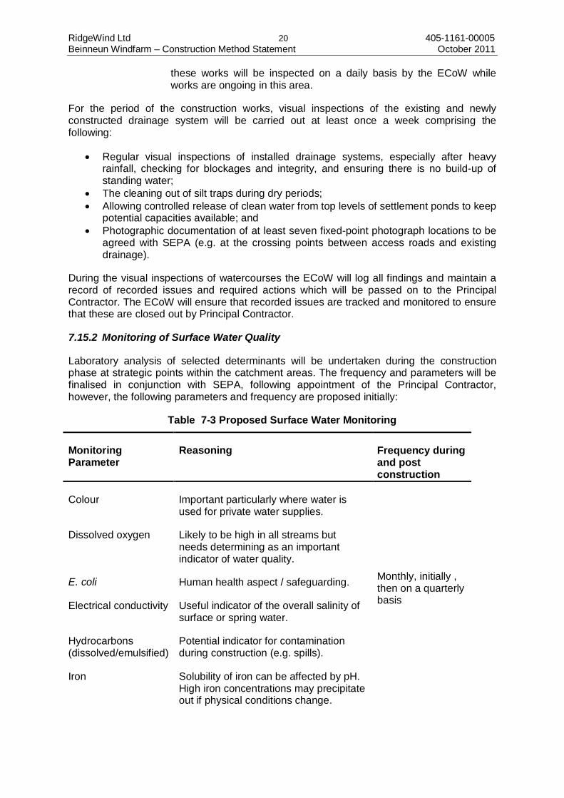
7.15.2 Monitoring of Surface Water Quality
Laboratory analysis of selected determinants will be undertaken during the construction phase at strategic points within the catchment areas. The frequency and parameters will be finalised in conjunction with SEPA, following appointment of the Principal Contractor, however, the following parameters and frequency are proposed initially:
Table 7-3 Proposed Surface Water Monitoring
Monitoring Parameter
Reasoning Frequency during and post construction
Colour Important particularly where water is used for private water supplies.
Monthly, initially , then on a quarterly basis
Dissolved oxygen Likely to be high in all streams but needs determining as an important indicator of water quality.
E. coli Human health aspect / safeguarding.
Electrical conductivity Useful indicator of the overall salinity of surface or spring water.
Hydrocarbons (dissolved/emulsified)
Potential indicator for contamination during construction (e.g. spills).
Iron Solubility of iron can be affected by pH. High iron concentrations may precipitate out if physical conditions change.

RidgeWind Ltd 21 405-1161-00005 Beinneun Windfarm – Construction Method Statement October 2011
Monitoring Parameter
Reasoning Frequency during and post construction
Manganese Potential increase i.e. indicator for erosion (soluble/leachable).
pH Overall water quality parameter.
Suspended solids Relevant to surface water quality/turbidity especially with regard to private water supplies / aquaculture.
* Post-construction: Initially for a period of 1 year, further monitoring as required by SEPA
The above parameters will also be monitored on a monthly basis for three months prior to commencement of construction works.
RidgeWind Ltd 22 405-1161-00005 Beinneun Windfarm – Construction Method Statement October 2011
8.0 PERMANENT WORKS
8.1 Introduction
The overall site design has been developed in accordance with recommendations adopted from the ES and to reflect the requirements and specifications for transporting wind turbine components to the consented turbine locations.
The extent of construction disturbance will be limited to around the perimeter of, and adjacent to, access track alignments, including associated earthworks, and shall be monitored by the ECoW as required.
In general, as part of the design mitigation wherever practicable all proposed site infrastructure has been sited at least 50 m from any watercourse.
It is anticipated that all access tracks will be constructed from aggregate won from local excavations and constructed to the best practices for windfarm access tracks. If site won material does not conform to required engineering specification for the final running surface then imported crushed rock material may be required.
Access tracks shall be constructed to a minimum running width of 5 m, plus shoulders of approximately 0.5 m on either side, to accommodate the maximum transport requirements and specifications of the WTS. Track shoulders may be up to a width of 2 m to accommodate cabling along the access track alignment.
Proposed access tracks will follow the existing contours to minimise the requirement for cut and fill and will be formed with a maximum gradient of 1:10. The proposed 4x4 access track will have a maximum gradient of 1:8.
The route of the new tracks will be surveyed and pegged out ahead of construction operations and agreed with the ECoW and ACoW. Setting-out shall be a minimum of 100 m ahead of the construction works (i.e. a minimum 1-day ahead of progress). Any deviations from the approved alignments, e.g. necessitated by the identification of sensitive receptors (ecological, ornithological, archaeological, hydrological, etc), shall be discussed and agreed with the Planning Authority, ECoW and ACoW, as appropriate.
For the construction of the road, peat and topsoil, where present, will be stored beside the road for use in reinstatement of road shoulders at the end of the construction period.
8.1.1 Existing tracks
The existing estate tracks will be upgraded as necessary to cater for the size and weight of delivery and construction machinery needed to build the Development. The upgrade works required will include widening, replacement of existing watercourse crossings and provision of intervisible lay-bys.
8.1.2 New tracks
The access to the site will be an upgrade of an existing access off the A887, which is located at the northern extent of the site boundary (see Figure 4.4a). As the delivery vehicles may turn right across the oncoming carriageway (depending on direction in which key components will be delivered), traffic management will be required during delivery periods. It is anticipated that all track upgrades and new tracks within the application boundary, will be

RidgeWind Ltd 23 405-1161-00005 Beinneun Windfarm – Construction Method Statement October 2011
constructed primarily from site won material. Additionally, a ‘4x4’ access will be developed into the site from the A87 and will typically be 3m wide with passing places/or road widening to 4m at suitable locations.
Access tracks will be formed on suitable underlying material (soil or rock with sufficient bearing capacity) in the following manner (see also Figure 4.5):
• Stripping of surface vegetation (turves) and careful stockpiling of this material; • Excavating the remaining superficial soil materials (overburden) and stockpiling this
material; • Where different overburden materials are present these will be stored according to
type. This material shall be monitored and watered (as appropriate) to be retained for reinstatement purposes;
• The exposed suitable track formation shall have rock fill material tipped from dumper trucks directly onto the proposed access track alignment; and
• This material shall then be either spread by a dozer or placed by a hydraulic excavator and compacted in layers, typically using vibratory rollers.
Turning areas will be formed to facilitate the turning of dumper trucks. These turning areas can serve as passing places during the construction period before being reinstated at the end of the works using subsoil/topsoil.
Access tracks shall be formed from a sub-base of general fill won from local excavations, and finished off with a cap-stone / wearing course of graded crushed rock to provide a nominal Type-2 (Series 800) finish. Wearing course stone shall be of a suitable material that is not susceptible to breaking down / weathering to a high fines content material.
Maintenance of the running surface will be carried out on a regular basis, as required, to prevent undue deterioration. Loose track material generated during the use of access tracks will be prevented from reaching watercourses by maintaining an adequate cross fall on the tracks. Periodic maintenance of tracks by way of brushing or scraping will be carried out to minimise the generation of wheel ruts, which could lead to some road material being washed away. In dry weather, dust suppression methods may be required for track and hardstanding areas. The site access tracks, hardstandings and trackside drains will be inspected on a daily basis by the Contractor. Records of such inspections will be held on site for review by the ECoW/Planning Authority.
8.1.3 Cut Roads and Drainage
In areas where the peat is shallow i.e. rockhead less than approximately 1.0 m below ground surface, the road formation will be created by a cut (and fill) or by a cut operation where the side slope is severe. A lateral drain will be established on the uphill side of the road to drain water from the slopes and cross drains will be established at intervals of no less than 30 m. Peat and topsoil, where present, will be stored beside the road for use in re-instatement of road shoulders. Consideration will be given to the potential for entrapment of snow and water in their placement.
Where the peat layer is of 1.0 m thickness or more and where the side slope is significant or where failure of the peat could result in landslip, the peat will be removed down to rockhead or suitable sub-soil horizon, leaving batters on each side with angles sufficient to ensure stability of the peat batter. Similarly, for excavations less than 1.0m, but where the local gradient gives concern with regards to the stability of the peat, then suitable slopes shall be cut back to ensure the peat batter is stable.
RidgeWind Ltd 24 405-1161-00005 Beinneun Windfarm – Construction Method Statement October 2011
A small double ditch will be established a few metres uphill of the batter to avoid significant water flow over it, thereby minimising erosion. The running surface of the road will have a cross fall in order to drain run-off into the ditches. A lateral drain will be made on the uphill side of the road with cross drainpipes at appropriate locations. The diameter of the cross drains will be calculated taking account of the catchment for each pipe. A ditch will be constructed on the low side of the track as necessary. The outlet of the drain will be at appropriate locations, with hessian/copra mats placed at the outfalls (where appropriate) in order to minimise erosion during periods of heavy rainfall or snow melt.
8.1.4 Floating Roads and Drainage
It is anticipated that the final design of the route alignment may be able to avoid deep areas of peat (>1.0m). Where however this is not possible, and where the existing ground gradient is relatively flat and the peat layer is of 1.0 m thickness or more, a floating road design may be required, ensuring that the risk of failure due to landslip is mitigated.
Floating road construction essentially comprises the laying of a geosynthetics (geotextile mat or geogrid reinforcement) across the peat prior to constructing the road. Where necessary, risk from run-off will be mitigated by directing drainage to settlement areas. Erosion processes on roadside embankments and cuttings will be mitigated by ensuring that gradients are below stability thresholds, which will also enable effective regeneration of vegetation. Sediment traps will be required in the early years following construction until natural regeneration is established. Should significant erosion or sedimentation, (which is not expected) take place at any location it will be addressed by re-grading and re-vegetating of slopes by hydro-seeding with heavy mulch. Seeding will be undertaken in consultation with SNH.
8.1.5 On Site Vehicle Movements
As noted above, access roads will be designed to be single track, a minimum of 5.0 m wide including the provision of intervisible passing places (See Figure 4.6) at appropriate locations taking account of horizontal and vertical track alignments. Additional widening will be provided on bends to facilitate the movement of the large delivery vehicles associated with turbine tower and blade delivery, and these will double as passing places where appropriate.
During the periods of delivery of the large components, the Contractor will use appropriate site communications and access control techniques to enable safe one way operation of the roads.
The presence of crane pads and lay-down areas will facilitate traffic movement on site. Internal track junctions will also be locally widened to facilitate multiple options for construction traffic movement. This will allow vehicles to move more directly between construction locations and double as passing places.
8.1.6 Unstable Ground
Unstable ground is herein considered to be any ground conditions encountered along the proposed alignment, or within the immediate vicinity and influence, of the access tracks that has insufficient strength in its existing state to support the proposed load conditions or to remain in situ for the duration of the construction works, or that has experienced natural failure (i.e. not as a consequence of the windfarm construction works) prior to, but along the alignment of, or within the immediate vicinity and influence of, the proposed access track alignment such as to require re-alignment of the works, or major civil engineering solution to maintain the proposed alignment.
RidgeWind Ltd 25 405-1161-00005 Beinneun Windfarm – Construction Method Statement October 2011
If any unstable ground is encountered during access track construction, the following procedure shall be adopted:
• Access track construction in the immediate area of the unstable ground shall cease with immediate effect;
• The Contractor shall immediately consult a suitably qualified and experienced geotechnical engineer; and
• If relocation within approved micro-siting allowances of the proposed access track alignment is possible and acceptable to the ECoW/ACoW (as appropriate) and the Planning Authority, without potential for further ground instability to occur, then construction may recommence along the newly agreed alignment, and any stabilisation / mitigation measures that may be required of the unstable ground shall occur in parallel.
8.1.7 Signage
Sufficient signage will be employed on site, for both site personnel and the public, to clearly define the boundary of the works where they coincide with areas accessible to the public.
8.2 Turbine Foundations
8.2.1 Introduction
A total of 25 No. Wind Turbine Generators (WTG’s) will be erected on reinforced concrete gravity foundations. The ground investigation data supports this foundation solution at all WTG foundation locations.
Proposed turbine foundation locations shall be inspected by the Contractor to ensure that all potential ecological and archaeological constraints have been identified, demarcated and/or mitigated for prior to the on-set of construction in that area. The final location of the turbines will be within approved micrositing allowances of the consented positions in accordance with Planning Conditions. The regularity of inspections (hourly, daily, weekly, as appropriate) during construction shall be determined in advance for each particular section, based on anticipated ground conditions, known ecological or archaeological sensitive receptors, prevailing weather conditions, and anticipated rate of progress.
8.2.2 Construction of Turbine Foundations
Construction of the turbine foundations shall be the responsibility of the Contractor.
The limits of each of the foundation excavations will be surveyed and pegged out at least two weeks in advance of any proposed works, and the ECoW and ACoW shall be consulted to ensure all necessary pre-construction checks have been completed.
The depth of concrete will vary across the base, depending on its shape and dimensions, tapering from around 0.8 m at the outer edges to around 2.5m where it meets the central plinth. Approximately 400-500m3 of concrete will likely be required for each turbine foundation, which will be imported externally, or batched on site if suitable aggregate can be sourced on site. The location of the batching plant will be within the proposed borrow pit between Turbines 11 and 16. Each turbine will also require steel reinforcement which will be delivered to site on a flat bed vehicle and then connected together to provide the reinforcing cage (see Figure 4.2)
RidgeWind Ltd 26 405-1161-00005 Beinneun Windfarm – Construction Method Statement October 2011
Although the turbine foundation will typically be 18m x 18m, the area of cut to allow the foundation to be constructed will typically be a larger area of 25m x 25m. This may be slightly greater to account for any cut slopes to be regraded to a stable gradient. This will allow safe batters to be excavated, and sufficient space to allow shuttering, placement of steel reinforcement and concrete teams to gain access.
The typical construction activities associated with the turbine foundation are detailed below:
• Stripping of surface vegetation (turves) and careful stockpiling of this material as per CEMP requirements;
• Excavating the remaining superficial soil and rock materials and stockpiling of this material as per CEMP requirements;
• The stockpiled materials are to be retained for restoration purposes; • Soil will be excavated until a suitable formation can be achieved. Where rock is
encountered this will most likely be removed by mechanical excavation to the required depth and material stockpiled as described above. The potential impacts associated with the use of hydraulic breakers or other such vibratory equipment in the vicinity of sensitive ecological receptors or watercourses shall be assessed and appropriate mitigation measures implemented where required in consultation with the ECoW;
• The foundation design is based on the most efficient use of materials and local ground conditions. From geotechnical investigations it has been shown that bedrock is at or near surface for all the proposed wind turbine locations;
• Temporary fencing shall be erected at locations where there are safety implications for any persons likely to be present on the site e.g. around open excavations. Signage will be displayed clearly to indicate deep excavations and any other relevant hazards associated with the foundation excavation works;
• Cut off ditches will be used at the perimeter of foundation excavations to divert the clean water away from the work areas thereby reducing the volume of water potentially requiring pumping/treatment in silt traps/settlement lagoons. It is not anticipated that large scale dewatering will be required during the excavations, which are to take place between the drier months of May to September. Water from dewatering of excavations shall be pumped via surface silt traps to ensure that sediment does not enter surrounding watercourses. Settlement lagoons will be employed in areas where the level of runoff is likely to exceed levels normally contained within a silt trap, however it is considered unlikely that these will be required. Wash-out areas at each base, (if required) will be lined and contained to prevent wash-out water entering drainage/surface waters. The material from the wash-out will be disposed of appropriately off-site;
• Following excavation, levels will be set to allow the blinding concrete to be placed and finished to the required line and level;
• The steel reinforcement shall then be finished to the required design specification. Most of the steel reinforcement will have been fabricated off site, and then delivered to site and stockpiled adjacent to the respective turbine base.
• The formwork will be pre-fabricated of sufficient quality and robustness to allow repeated use. Formwork will be cleaned after each use and re-sprayed or painted with mould oil within the blinded foundation excavation prior to being fixed in place. The placement of containers with mould oil will be strictly monitored to ensure that storage is only in bunded areas (i.e. in the TCC) on sealed hardstanding. Spraying of mould oil and storage of such sprayed materials will be undertaken in such as way as to avoid pollution;
• Sulphate resistant concrete or other suitable concrete, as appropriate for the prevailing ground conditions, will be used in the turbine base. Prior to pouring the
RidgeWind Ltd 27 405-1161-00005 Beinneun Windfarm – Construction Method Statement October 2011
base concrete, the overall quality of the steel fixing will be checked to ensure there is sufficient rigidity to cope with the weight of personnel and small plant during the pour. The quantity, size and spacing of the reinforcement bars will be checked against the construction drawings to ensure compliance with the design detail. The position of the foundation insert, or other appropriately designed foundation mechanism supplied by the turbine manufacturer will be checked to ensure that the level is within the prescribed tolerances. A check will also be carried out to make sure the correct cover from edge of reinforcement to edge of concrete is maintained throughout the structure. A splay will be formed on all external corners;
• The line of ducts will be checked so as not to leave sharp corners that will cause cable snagging and that all bend radius comply with the design illustrated on the construction drawing. All earthing cable or strip connections will also be examined to prove their adequacy to withstand the rigors of the concrete placing process;
• Concrete will be supplied from a ready-mix source off site, providing that no on-site source for aggregates is found. As with all concrete deliveries, a record shall be kept against each turbine to indicate the source of supply, type and consistency of the mix. A record will also be kept of the personnel involved, the time and date the pour commenced and finished;
• The concrete pour will commence after the blinding concrete has been cleaned of debris and other loose material. Vibrating pokers will have been checked to ensure they are fuelled by compressed air and in good working order. The pour will proceed under the control of the Contractor. Personal Protective Equipment (PPE) will be worn by the site operatives and as detailed in the Construction Phase Plan. Pouring will follow best working practice procedures and fresh concrete will be protected from hot and cold weather as required;
• Shutters will be carefully loosened, removed and cleaned no earlier than 24 hours from the finish of the pour; and
• Backfilling to the turbine base will proceed in layers of approximately 0.3 m with compaction as necessary. Further layers of material will be laid until the original till level is attained. Peat or soil will be replaced from storage until the original ground level is reached, or a shallow mound (up to 500 mm above existing ground level) is formed. In the event that there is limited on site material to compact above the turbine foundation, then imported material may be required. This will typically be a well graded granular product that should be available from the on site borrow pits.
A checklist for each foundation will be prepared to show compliance with the documents of each step of the installation process. These lists, once completed, will be stored in the contractor’s QA file along with relevant cube test results, and be available for inspection at all times.
Following the completion of all construction activities, the area surrounding the base shall be reinstated.
8.3 Crane Pads
Crane pads measuring approximately 40 m x 28 m will be required to allow installation and removal of the turbine components. Location and orientation will be optimised to make best use of the existing topography, prevailing wind conditions (to enable safe lifting) and the chosen erection procedure. Additionally, the crane pad will orientation will take account of ecological or other constraints. As with access tracks, turfs topsoil and subsoil will be removed wherever possible and stored separately adjacent to the removal area for later reinstatement up to the edge of the hardstanding.

RidgeWind Ltd 28 405-1161-00005 Beinneun Windfarm – Construction Method Statement October 2011
The area will be set out to the required dimensions (typically a main crane and a tail crane pad will be required) and excavated to a suitable formation. Coarse rock fill will then be placed and compacted in layers using compaction equipment. Geotextile may be used depending on the suitability of the underlying strata. The final surface will be formed from selected granular material and trimmed to allow surface water run-off to drainage ditches. The crane pad will remain in situ for the operational life of the Development, although may be partially covered with excavated materials and seeded with a local seed mix.
The crane pads will be covered with local peat/topsoils and seeded with a local seed mix upon decommissioning of the site. The final ground level will be profiled to suit the surrounding ground.
8.4 Control Building and Sub-Station
A single storey blockwork control building would be constructed on a pre-cast concrete base (installed on a levelled area). The building’s external finishes would be agreed in consultation with Highland Council and the landowner.
Welfare facilities including a toilet will be provided for the duration of the operation of the Development. Sewage waste will be tankered off site by a licensed approved waste contractor.
A rainwater collection and purification system may be installed to service the welfare room, and electricity will be provided from a local electricity connection or a back-up diesel generator.
The proposed sub-station would be located as part of the control building compound. This is also close to the nearby overhead transmission/power lines which cross the A887 close to the site entrance. The compound will be accessed from the windfarm access track, with enough space for parking of a small number of staff/servicing vehicles. The control building is located close to the site entrance and public road to assist access during inclement weather such as snow.
The detailed design and construction of the switchgear would be undertaken by Scottish and Southern Electricity under a separate contract to the main windfarm construction. The final design and construction methods will be agreed with Highland Council.
Typically the structure/building will be a single storey steel framed structure, with an external finish to suit any specific visual/aesthetic requirements. The structure will be located on a concrete plinth, and the switchgear within a hardstanding/concrete area.
Lighting will be limited within the compound and would be limited to emergency flood lights around the switchgear, security/motion sensor lights to building, and then any internal lighting within the building.
Figure 4.8a and 4.8b provide details of a typical sub-station compound and building.
8.5 Cable Laying
Turbines will be connected to the grid via a new substation. Underground power cables will be run beneath between the turbine site and the substation laid in a trenching operation c. 500 m long at one time. The power system is 3-phase, with a separate cable required for each, hence a 3-cable bundle will be laid in the trench. The proposed layout runs the cables along new access tracks. Cable trenches will be approximately 1.25 m wide and 1.1 m deep, where three sets of 3-phase cables are required (between the wind turbine site and
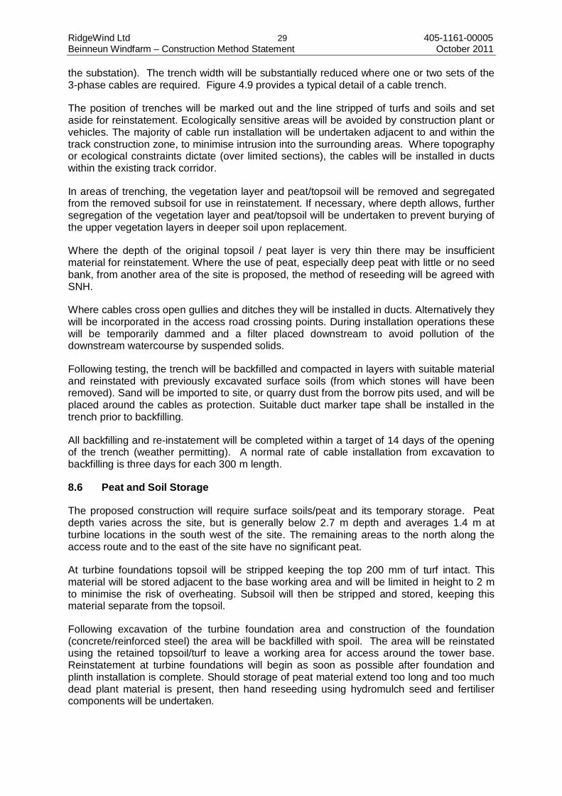
RidgeWind Ltd 29 405-1161-00005 Beinneun Windfarm – Construction Method Statement October 2011
the substation). The trench width will be substantially reduced where one or two sets of the 3-phase cables are required. Figure 4.9 provides a typical detail of a cable trench.
The position of trenches will be marked out and the line stripped of turfs and soils and set aside for reinstatement. Ecologically sensitive areas will be avoided by construction plant or vehicles. The majority of cable run installation will be undertaken adjacent to and within the track construction zone, to minimise intrusion into the surrounding areas. Where topography or ecological constraints dictate (over limited sections), the cables will be installed in ducts within the existing track corridor.
In areas of trenching, the vegetation layer and peat/topsoil will be removed and segregated from the removed subsoil for use in reinstatement. If necessary, where depth allows, further segregation of the vegetation layer and peat/topsoil will be undertaken to prevent burying of the upper vegetation layers in deeper soil upon replacement.
Where the depth of the original topsoil / peat layer is very thin there may be insufficient material for reinstatement. Where the use of peat, especially deep peat with little or no seed bank, from another area of the site is proposed, the method of reseeding will be agreed with SNH.
Where cables cross open gullies and ditches they will be installed in ducts. Alternatively they will be incorporated in the access road crossing points. During installation operations these will be temporarily dammed and a filter placed downstream to avoid pollution of the downstream watercourse by suspended solids.
Following testing, the trench will be backfilled and compacted in layers with suitable material and reinstated with previously excavated surface soils (from which stones will have been removed). Sand will be imported to site, or quarry dust from the borrow pits used, and will be placed around the cables as protection. Suitable duct marker tape shall be installed in the trench prior to backfilling.
All backfilling and re-instatement will be completed within a target of 14 days of the opening of the trench (weather permitting). A normal rate of cable installation from excavation to backfilling is three days for each 300 m length.
8.6 Peat and Soil Storage
The proposed construction will require surface soils/peat and its temporary storage. Peat depth varies across the site, but is generally below 2.7 m depth and averages 1.4 m at turbine locations in the south west of the site. The remaining areas to the north along the access route and to the east of the site have no significant peat.
At turbine foundations topsoil will be stripped keeping the top 200 mm of turf intact. This material will be stored adjacent to the base working area and will be limited in height to 2 m to minimise the risk of overheating. Subsoil will then be stripped and stored, keeping this material separate from the topsoil.
Following excavation of the turbine foundation area and construction of the foundation (concrete/reinforced steel) the area will be backfilled with spoil. The area will be reinstated using the retained topsoil/turf to leave a working area for access around the tower base. Reinstatement at turbine foundations will begin as soon as possible after foundation and plinth installation is complete. Should storage of peat material extend too long and too much dead plant material is present, then hand reseeding using hydromulch seed and fertiliser components will be undertaken.

RidgeWind Ltd 30 405-1161-00005 Beinneun Windfarm – Construction Method Statement October 2011
The risk of water pollution from peat excavation in terms of sediment loss will be prevented/mitigated by the following measures:
• Careful location of turbine bases and road line to minimise peat excavation where applicable;
• Stripped peat will not be stored adjacent or in close proximity to watercourses, where a construction area requiring peat stripping is close to a watercourse the peat will be stored a suitable distance from the watercourse;
• Peat will be stored correctly to remain intact as the peat will be essential to the site reinstatement;
• Where turf/peat requires excavation for road construction an excavator will lift turf and place it to the side leaving space between the edge of the road and the embankment to be constructed. The excavator will then lift out the peat and will place it to the side of the proposed road. Following construction of the road, the side cast peat will be graded by an excavator and the peat turfs will be replaced by the excavator over the graded peat beside the road. The timescale for this operation is short and the methodology has been successfully applied at other windfarms;
• Excavated peat will not be side-cast onto water reservoirs (within peat), or placed where it will block established surface or sub-peat drainage channels; peat will be spread carefully to avoid point overloading of underlying peat layers; and
• In order to avoid the risk of peat slide, excavated peat will not be stacked at the top edge of the convex slope.
8.7 Water Crossings
8.7.1 General
This section concerns the proposed operations required for watercourse crossing works in areas associated with the Development. This document shall be used by the Contractor in developing the detailed design of all watercourse crossings prior to construction.
Appendix A9.2 of the ES details the watercourse crossings that have been identified during the production of the ES. It is possible that due to the results of more detailed investigations carried out prior to construction, and micrositing carried out during construction, that a number of these crossing locations may change.
The Contractor is required to produce a detailed Watercourse Crossing Plan prior to commencement of the works. This plan shall be submitted to the Employer, ECoW and SEPA for review and approval where appropriate.
The Contractor is responsible for liaising with and obtaining from SEPA all relevant consents, licenses and authorisations relating to construction of water course crossings at the Site.
All construction works on the Site, and specifically construction works to be undertaken within and in the vicinity of any watercourses, shall be completed in compliance with current legislation and best practice as detailed within this document.
As part of the design mitigation all wind turbine locations, site compounds, and other permanent and temporary structures (with the exception of roads) have been sited with a minimum separation of 50 m from watercourses and drainage runs where possible. This has been achieved with the exception of two turbines (T4 and T18) which have been sited 47 m from the nearest watercourse.

RidgeWind Ltd 31 405-1161-00005 Beinneun Windfarm – Construction Method Statement October 2011
Roads have been routed to stay away from watercourses, where possible. However, as roads are required to cross watercourses at certain, limited, locations appropriate and careful design and construction of watercourse crossings is required.
The ECoW shall be consulted on all Watercourse Crossing works. Surveys by the ECoW will be carried out immediately prior to construction of the crossings to identify areas of ecological interest and more specifically, mammal and fish activity in watercourses to ensure that adequate mitigation is built into the design.
8.7.2 Design Philisophy
The Development construction will cover areas where watercourses (rivers, streams, burns and drains) exist. The Controlled Activities (Scotland) Regulations 2011 (CAR regulations) require that all new river, loch and wetland engineering activities, including river crossings and culverting for watercourses shown on the Ordnance Survey 1:50,000 scale map, will require authorisation by SEPA, which may include (depending on the nature of the works) Registration with, or a Licence from, SEPA. Even if a proposed crossing does not require a Registration or Licence, due to its compliance with a General Binding Rule (GBR), as defined in the CAR regulations, SEPA are still required to be notified.
General good practice in Watercourse Crossing design will ensure that various conditions will be taken into account during the works, and are summarised below:
i) All watercourses, over which the access roads cross, will be routed through bottomless culverts or under bridges appropriately sized and designed not to impede the flow of water and will allow safe passage for wildlife, such as fish, water voles, otters etc (i.e. the crossings will have a capacity well in excess of the design flow);
ii) When installing culverts, care will be taken to ensure that the construction does not pose a permanent obstruction to migrating species of fish, or riparian mammals (i.e. the crossings will make provision for fish and wildlife migration);
iii) Culverts should be sized so that they do not interfere with the bed of the stream during construction, (i.e. the crossings will leave the watercourse in as natural condition as possible);
iv) Culverts with a single orifice will be used in preference to a series of smaller culverts that may be more likely to become blocked with flotsam and create erosion (i.e. the crossings will not constrict the channel);
v) Although no fish have been recorded within the tributaries running through the site, if any fish are found during the construction of any culverts they will be removed from the immediate construction site to a place of safety if deemed necessary after consultation with the relevant fisheries interest;
vi) To minimise impacts on breeding of any fish found, then any in-stream works in these areas will be conducted during months which have less impact on their breeding and development, where possible;
vii) Ease and speed of construction are important to minimise disruption to the watercourse and surrounding habitat;
RidgeWind Ltd 32 405-1161-00005 Beinneun Windfarm – Construction Method Statement October 2011
viii) Designed for the life of the project;
ix) Low maintenance; and
x) Visually in keeping with the surroundings
In accordance with the guidelines laid down in the CAR guidance, each Watercourse Crossing shall be designed on a case by case basis to be appropriate for the width of watercourse being crossed, and the prevailing ecological and hydrological situation (i.e. the “sensitivity” of the watercourse). A number of factors, both environmental and engineering will influence the selection of structure type and the design of the crossing.
If stream diversion is considered necessary to minimise the impact when crossing a watercourse at a particular location, SEPA and the ECoW would be consulted.
All watercourse crossings shall include splash boards and run-off diversion measures to prevent direct siltation of watercourses.
8.7.2 Structural Design
Once a watercourse crossing has been identified, consideration needs to be given to aspects such as:
• Bearing capacity of foundations (and variability of capacity); • Design loadings – likely to be larger during construction and decommissioning of the
Development; and • Design Options such as bridges or culverts.
8.7.3 Culverts
Medium to large bottomless culverts or large Armco culverts will be used where a culverted solution is desirable or where a small piped culvert is not appropriate for environmental or channel-size reasons. The advantages of a bottomless culvert over a circular culvert is that a more natural river bed can be reinstated and maintained.
A natural stone headwall will be provided upstream and downstream to protect the road embankment where necessary. Further protection will be provided to the banks using soft engineering techniques as much as possible. 8.7.4 Bridges A bridging solution has been identified for a watercrossing point between Turbines 17 and 18.
Bridges are the preferred solution for larger spans, and for higher flow watercourses. Bridge construction is less likely to interfere with the watercourse to the same extent as culvert construction, and can be built over the existing alignment of the river without the need for diversion. Foundations will be required on both banks (down to a competent bearing stratum) in order to support the bridge deck.
It is anticipated that spans up to 10 m can be constructed using pre-cast concrete beams. Spans greater than 10 m may be constructed using a proprietary bridge decking system. It

RidgeWind Ltd 33 405-1161-00005 Beinneun Windfarm – Construction Method Statement October 2011
may be necessary, depending on the local conditions to provide a revetment protection to the bridge supports. It may also be necessary to provide bed protection.
The design of the abutments will depend on local ground conditions. Where possible the foundation will be excavated to material which will provide the required bearing pressures.
The watercourse will then be crossed with either pre-cast beams or proprietary decking systems depending on the span. These will be delivered to site on a HGV and a suitably sized crane used to lift the decks into place. Local widening and strengthening of the road would be required on one side of the bridge to accommodate the crane.

RidgeWind Ltd 34 405-1161-00005 Beinneun Windfarm – Construction Method Statement October 2011
9.0 OPERATIONAL PHASE
9.1 Reinstatement and Monitoring
9.1.1 General
For all reinstated areas, immediate aftercare provision will include an inspection of reinstated areas after completion of the reinstatement work at each location. It is proposed that an annual monitoring programme will be undertaken for a minimum of 5 years (see below). In addition, regular maintenance visits to the site will be undertaken and will include visual monitoring of the success of re-vegetation. In cases where re-vegetation is not as successful as required advice will be sought from the ECoW/SNH on necessary remedial action.
Erosion processes on roadside embankments and cuttings will be mitigated by ensuring that gradients are below stability thresholds, which will also enable effective regeneration of vegetation. Sediment traps will also be required in the early years following construction until natural regeneration is established. Should significant erosion or sedimentation, which is not expected, take place at any location it will be addressed by re-grading and re-vegetating of slopes by hydro-seeding with heavy mulch. Seeding will be undertaken in consultation with SNH.
9.1.2 Reinstatement Methods (Outline)
Reinstatement will be undertaken either by re-use of onsite vegetation and soil (mainly peat) using turf/clodding methods, or by re-seeding using species compositions designed to mimic natural succession following fire (muirburn). Proposed methods will be finally agreed and confirmed with SNH, SEPA and Highland Council following appointment of the Principal Contractor.
9.1.3 Monitoring Methods (Outline)
Vegetation monitoring will be undertaken through the use of semi-permanent quadrats (at locations to be agreed with SNH) immediately following reinstatement and at the end of the first growing season (year 1). A record will be made of the vegetation and surface conditions.
Monitoring will be repeated in May/ June and September from years 2 to 5 following construction. A photographic record will also be maintained at fixed photographic locations.

RidgeWind Ltd 35 405-1161-00005 Beinneun Windfarm – Construction Method Statement October 2011
10.0 DECOMMISSIONING AND REINSTATEMENT
10.1 Site Details
The decommissioning will effectively be the construction procedure in reverse. A compound will be established for the storage of plant, equipment and fuel, including bunding as required, together with welfare and mess facilities.
Initially, the turbine nacelles and blades will be removed, followed by dismantling of the towers. Underground cables will be left in situ or removed from site for disposal/recycling in accordance with applicable waste disposal regulations at the time of the works. The bulk of the concrete foundations will be left in situ, but exposed parts may be chipped away. Restoration of each location and the compound will be achieved by covering these with the stored subsoil and topsoil materials. Appropriate grass seed/heather mix will be sown on the restored turbine and compound areas.
The duration of the decommissioning phase is expected to be around 6 months.
Records of the location of remaining structures and cabling will be recorded in the site’s Health and Safety File.
RidgeWind Ltd 36 405-1161-00005 Beinneun Windfarm – Construction Method Statement October 2011
11.0 REFERENCE DOCUMENTS
Doc Ref
Reference Documents
1 Control of Water Pollution from Construction Sites, Guidance for Consultants and Contractors, CIRIA, 532, 2001
2 Control of Water Pollution from Linear Construction Projects, technical guidance, CIRIA 648, 2006
3 Non-Statutory Guidance for Site Waste Management Plans, April 2008
4 Forest & Water, Guidelines, 4th Edition, 2003
5 Health and Safety at Quarries. Quarries Regulations 1999. Approved code of practice, HSE, 1999
6 River Crossings and Migratory Fish: Design Guidance, 2000
(available from: www.scotland.gov.uk/ consultations/ transport/rcmf-00.asp)
7 Engineering in the Water Environment, Good Practice Guide, Construction of River Crossings, First Edition, April 2008 (WAT-SG-25)
8 Mineral Extraction Code of Practice for the Owners and Operators of Quarries and Other Mineral Extraction Sites, Water Environment (Controlled Activities) (Scotland) Regulations, 2005, Version 1 July 2006
9 Prevention of Pollution from Civil Engineering Contracts: Special Requirements, Version 2 June 2006
10 Prevention of Pollution from Civil Engineering Contracts: Guidelines for the Special Requirements, Version 2 June 2006
11 The Water Environment (Controlled Activities), (Scotland) Regulations 2005, A Practical Guide, Version 5, June 2008
Pollution Prevention Guidelines (PPGs)
http://www.netregs.gov.uk/netregs/links/107968.aspx
12 PPG1 General Guide to the Prevention of Pollution: PPG1
13 PPG2 Above Ground Oil Storage Tanks: PPG2, April 2010
14 PPG3 Use and design of oil separators in surface water drainage systems: PPG 3, April 2006
15 PPG4 Treatment and disposal of sewage where no foul sewer is available: PPG4, July 2006

RidgeWind Ltd 37 405-1161-00005 Beinneun Windfarm – Construction Method Statement October 2011
16 PPG5 Works and maintenance in or near water: PPG5, October 2007
17 PPG6 Working at Construction and Demolition Sites: PPG6, July 2010
18 PPG7 Refuelling Facilities: PPG7, August 2004
19 PPG8 Safe Storage and disposal of used oils: PPG8, February 2004
20 PPG21 Incident Response Planning: PPG 21, March 2009
21 PPG26 Storage & handling of drums & intermediate bulk containers: PPG 26, February 2004

RidgeWind Ltd 38 405-1161-00005 Beinneun Windfarm – Construction Method Statement October 2011
12.0 DISCLAIMER
This report has been prepared by SLR Consulting Limited with all reasonable skill, care and diligence, and taking account of the manpower and resources devoted to it by agreement with the client. Information reported herein is based on the interpretation of data collected and has been accepted in good faith as being accurate and valid.
This report is for the exclusive use of RidgeWind Ltd; no warranties or guarantees are expressed or should be inferred by any third parties. This report may not be relied upon by other parties without written consent from SLR.
SLR disclaims any responsibility to the client and others in respect of any matters outside the agreed scope of the work.

![Introduction to Quantum Information Processingjyard/qic710/Qic710Lec8-2017.pdf · Exercise: why are 2 bits ... Appendix A4.4 in [Nielsen & Chuang] ... with probability 𝛼2 2 * Showing](https://static.fdocuments.in/doc/165x107/5b51820c7f8b9ac4368c45eb/introduction-to-quantum-information-jyardqic710qic710lec8-2017pdf-exercise.jpg)