APPENDIX A SUMMARY OF DISPERSION MODELING AND RESULTS
153
APPENDIX A SUMMARY OF DISPERSION MODELING AND RESULTS \'°!.APPLiEDVR3S20-09.TBP AR3M223
Transcript of APPENDIX A SUMMARY OF DISPERSION MODELING AND RESULTS
APPENDIX A
SUMMARY OF DISPERSION MODELING AND RESULTS
\'°!.APPLiEDVR3S20-09.TBP
AR3M223

Dispersion modeling was carried out using EPA's VALLEY model, andsite-specific meteorological data. The Valley Model was selected because it isone of the 40 CFR 266.206 acceptable models for complex terrain. Generalrequirements for data input to the EPA's VALLEY dispersion model are describedin this section, along with stack parameters. These data requirements fall inthree main classifications: meteorological data, receptor data, and source data.Model options selected for this study are also discussed. Finally, model resultsare summarized in this section.
1. Meteorological Data
The general meteorological data requirements are .a stability-windsummary, ambient pressure and temperature, mixing heights, and mean speedsof the wind speed classes. The most critical input is the stability-wind rose(STAR) data subset, which represents the joint frequency distribution of windspeed and direction for each of the six Pasquill-Gifford stability classes (Athrough F). One years worth of on-site meteorological data was used to 'developthe (STAR) data subset.
The remaining general meteorological data requirements were assignedas follows:
• ambient pressure—760 mmHg• ambient temperature—20°C (293 K)• mixing height—5000 m• mean wind speeds by class—(0.670, 2.450, 4.470, 6.930, 9.610, and12.52 m/s)
MR!-APPUED\R3S20-09.TBP A"2
HR3II221*

2. Receptor Data
IDThe VALLEY model generates 112 receptors at seven distances along 16radial directions. The user of the model controls only the scaling factor whichdetermines the distance between successive receptor locations. Scaling factorsof 1:1,200, and 1:24,000 were used. The scaling factors were used to representthe surrounding terrain and concentration isopleths. The 1:1,200 scale was usedwith "flat terrain" to model impact in the area immediately surrounding the site.The second scale was used to account for the effect of complex terrain surround-ing the site. The ground elevation at each receptor is required as input. Theseelevations were determined from United States Geological Survey (USGS)topographic maps.
3. Source Data
Table 1 summarizes the source data used in the VALLEY model.
____ - ______ Table 1. SOURCE DATASource Type StackStack Diameter 1.83 m (Q ft)Stack Gas Velocity 1 4.39 m/s (2832 ft/miri)Stack Gas Temperature 361.5 K (191 °F)Stack Height ___________ . 150ft
4. Model Options
VALLEY allows a half-life option to account for removal of the pollutant.This option was not used since the maximum dilution factor was to be
MRI-APPLIED\R3620-09.TBP
AB3I I225

determined. Buoyancy-induced dispersion and gradual plume rise were selectedsince the source was the stack at a temperature of 191°F.
5. Results
The dispersion modeling was used to define the point of maximumambient air concentration outside the plant boundary. This point was determinedas a result of terrain effects (i.e., scale of 1:24,000) and was found to be approx-imately 1.8 km south-southeast of the stack. The VALLEY model output wasexpressed in terms of ambient air concentration (|ig/m3) for a unit emission rate(i.e., one gram per second). The ground level ambient air concentration at thepoint of maximum concentration is 1.58 (ig/m3 at a 1-g/s emission representing adilution factor of approximately 1.6 u.g/m3/g/s.
W.=.-APPLIED'S3S20-09.TBP A"4
I226

APPENDIX B
USE OF CO2 CORRECTION FOR CO, PARTICULATE, AND DIOXINCONCENTRATION CALCULATIONS
MHI-APPllcD\R3620-09.TBP ' I
AK3II227

In a conventional incinerator, the CO and particulate emissions arerequired to be corrected to 7% O2 using the following equation:
p _ = I 14rc ~ V21 - %02J
where: Pc = corrected pollutant concentrationPM = Measured pollutant concentration
%O2 = Percent O2 measured in stack gas
Those incinerators that use oxygen enrichment would, in effect, bepenalized by this correction. Thus, EPA allows an alternate correction methodfor such facilities as follows: •
D _ n ( 14 "IM(E-%02J
•
where: E = the %O2 in the enriched combustion air fed to the incinerator
It has been recognized by EPA and others that quantifying and controllingthe oxygen enrichment on the combustion air is difficult and may not be known.For that reason, alternate oxygen correction factors have been derived foroxygen-enriched incinerators, as presented in the attached article.1
One of the methods derived for correcting the pollutant concentrationutilizes the CO2 concentration (dry basis) measured in the stack gas, and can bewritten as follows (per Equation 14 in Reference 1):
(% CO2)a 7(% C02)fl
1 Garg S. and C. Castaldini, "Derivation of Oxygen Correction Factors forOxygen-Enriched Incinerators," Journal of the Air Pollution Control Association,November 1987, pg. 1462.M=I-APPUED\R3620-09.TBP ' B"2
AR3M228

where: (% CO2)a7 = percent dry CO2 that would be measured in a. conventional incinerator operating at 7% O2 lll|r
(% CO2)e = percent dry CO2 measured in the oxygen-enrichedincinerator
The article1 provides a figure (Figure 1 in Reference 1) for determining thevalue of (% CO2)a7 based on the carbon-hydrogen molar ratio, and level ofchlorine, in1 the total combustible feed to the incinerator (i.e., combustible feedsand fuels). It is proposed that- the preceding equation be used to calculatecorrected values for CO, dioxin, and particulate emissions from the Drakeincinerator. More specifically, the equation would be as follows, using a value of8.5for(C02)a7: •
(8.5)
Since the Drake incinerator will be feeding contaminated soil with aheating value of < 250 Btu/lb, this is not a combustible fuel. In fact, the onlycombustible fuel will be the natural gas used to fuel the incinerator. The naturalgas is primarily methane (CH4) having a C/H molar ratio of 0.25. Other minoramounts of combustible in the natural gas would slightly increase the C/H ratio,but even considering the POHC and PVC feed during the trial burn; the C/H ratiowill not exceed 0.30. At a conservatively high C/H ratio of 0.30, the value of(CO2)a7 would be 8.5 (from Figure 1 in Reference 1).
The above equation is proposed for use at the Drake incinerator based onthe ability to reliably measure the CO2 concentration in the stack gas versus thedifficulty in accurately determining the percent oxygen in the enriched combustionair fed to the incinerator.
MHI-APPLIED\R3620-C9.TBP B"3
AR3II229

JAPCA NOTE-BOOKDerivation of Oxygen Correction Factors
for Oxygen-Enriched incinerators
,,,p . D Carlo CastaldiniU.S. Envronmen aHProteotion Agency Acurex Corporation
washmgton, DC Mountain View, California
Compliance monitoring for hazardous waste incinerators re- mquires that the pollutant concentration measured in the 100 Ve + 21 Vastack gas be corrected to 7-percent oxygen level. In a conven- —'tional air supply incinerator, this is easily done by applying E ,= —————~———— (2)the well-known correction factor (40 CFR 264.342): Ve -(• Y Va
PC = Pm X Na/Na- = Pm X 14/(21 - 02) (1) —, where:where:„ . , , „ , , t .„. . ,, . Ve is the volumetric feed rate of pure oxygenPm is the pollutant volume concentration, typically in •,, . ., , . , , ;is the volumetric feed rate of
plies at 21 percent oxygenis the number of combustion ileakage ports in draft systems
is the pollutant volume concentration, typically in .7 Is Cne volumetric teed rate or pure oxygenppm on a dry basis Va Is the volumetric feed rate of conventional air sup-
Pc is the concentration corrected to 7% 02 • fiies at 21 percent oxygenNa-; is the volume of dry stack gas at 7% 02~ m }s the number of combustion air inlets including in-Na isthevolumeofdrystackgasatactualconditions.and wu leakage ports in draft systems02 is the percent dry oxygen concentration at actual ca n ;fn1ffin,fn o?r ?liLC_aill0!.Le:-C°f!.trolle as.in thecase of significant air inleakage or variable combustion air
supply, two alternate correction factors, based not on E, butSome hazardous waste incinerators are equipped with an on the measured stack gas concentrations of CC>2, have been
oxygen-enriched combustion air supply to improve operat- developed.ing performance and enhance hazardous waste treatmentcapacity. A hazardous waste incinerator operating with an Oxygen Correction Factor Based on Enrichment Level Eoxygen-enriched combustion air supply will generate lower •volumes of combustion gas than a conventional air supply The correction factor is simply the ratio of the volumes ofincinerator of the same capacity. Consequently, for the same combustion gas in the enriched and nonenriched systems.mass emission rate, the volumetric concentration of a pollut- That is:ant in the stack gas of the oxygen-enriched incinerator will pc _ n x >r / •be higher than that measured in the stack of a conventional . ' •• 'air supply incinerator. In a regulatory compliance scenario, where Ne is the volume of dry stack gas (where the pollutantthis higher concentration would result in a penalty for an measurement is made) from the oxygen-enriched incinera-incinerator with an oxygen-enriched air supply unless an . tor- In order to solve the ratio Ne/N<n in terms of the enrich-adjustment were made to account for the reduced stack gas ment factor E, the derivation used to arrive at Equation 1 isvolume. . used-This article presents the mathematical derivation of oxy- The Principal chemical species in the combustible feed
gen correction factors to convert pollutant concentration tnat Participate in the combustion process are carbon (C),measured in an oxygen-enriched incinerator to an equiva- hydrogen (H), fuel bound oxygen (02), chlorine (Cl) andlent concentration that would be measured in a convention- other halogens, and sulfur (S). The volume of dry gas gener-al, nonenriched air supply incinerator operating at 7 percent ?te from a ""•** weight of combustible feed to a nonenrichedoxygen in the stack gas, such that the mass emissions from incinerator can be calculated as follows:the two incinerators are the same. Although the discussion Na - (HC + ns) (1 + 79/21) + 79/21 (1/4) (nH - nCi)focuses on hazardous waste incinerators, the correction fac- , /, , __/,,.> „«/„..tors apply to any combustion device. + n^ d + 79/21) - 79/21 no, (4)Three separate correction factors have been developed. where nz is the mole of constituent X per unit weight of
The first correction factor assumes that the oxygen enrich- combustible feed, e.g., net *> (percent weight chlorine)/3550.ment. E (where £ is a value greater than 21 percent); for the The factor 1/4 accounts for the fact that it takes two hydro-total combustion air to the incinerator can be quantitated §en atoms for each oxygen atom in the 02 molecule to makeand controlled. This is often not the case because the en- water.riched air supply is typically one of two or more air supplies Substituting the following equation for the dry concentra-te the incinerator system such that E can vary according to ^on °f oxygen measured in the stack gas:the following equation:
EOCopyright 1989— Air & Viau Muugement Auocwuon '"2 = ~~ X "" (5)

into Equation 4 and arranging the terms yields: correction.factor becomes simply:
-Va- Ne/Na:=
100 (nc + ns) + (——7 -) (nH - na) - (100 - 21) n0. wherp %a, .„ tlno Arv __on concentration measured in________ _______________________________\__________•»_________/ - ——~ ~ ~J "- —— J O~~ ~~ —— --—— ——— —— —— -—— ————-——««»%,«. 411
21 - %0o stack gas emitted from the oxygen-enriched incinerator2 the limiting case, when F3 0, the correction factor redu._.,
(6) to Equation 1 for no oxygen enrichment. The effect of theterm in parentheses in Equation 9 is generally very small and
For an oxygen-enriched incinerator, the volume of com- can be disregarded. This is easily verified by substitutingbustion gas can be calculated using Equation 6 and substi- high values for chlorine and F to determine the "reatesltuting the enrichment level E for 21 where E > 21. There- possible effect. For example, liquid hazardous°wastesfore, Equation 6 becomes: burned without fuel supplement can contain as high as 40Me m percent chlorine by weight. Assuming carbon and hydrogen.
concentrations of 55 and 5 percent, respectively, and that100 (nc + n.) + f10°"gNl (nH - na) - (100 - E} n0 the oxygen enrichment is 50 percent (i.e.,F= 29), the term in
L \ 4 ) " u________j parentheses becomes 0.947, which represents only 5.3 per-E — %0o cent error disregarded. For a system burning pure oxygen.
(i.e., F « 79) the error in Equation 10 escalates to about 1-1and the correction factor Ne/Na-; becomes: percent in the example. In most cases, the error is signifi-
' • cantly smaller because oxygen and chlorine levels in theNe/Na- = ——— combustible feed are not sufficiently large to have an impact
E - %02 on the oxygen utilization in the combustion air supply. Also,the level of oxygen enrichment typically does not exceed 35
mnc j. x , /100-£\ , > Mnf> n-\ -i percent because of cost considerations and temperature lim-100 (nc + ns) + (——-——}(nH-na)-(lQQ-E)n0^ itation of combustor material.
Alternative Correction Factor100 (nc + ns) + 79/4 (nH - na) - 79 n0,
(8) Two approximations to the correction factor in EquationDefining the percent enrichment as F, where F = E - 21, and 10 can be used when the value of E is not known or cannot beby arithmetical manipulation, Equation 8 becomes: controlled. Both methods require the measurement, of C0;:
14 in the combustion gas and the quantitation of the hydrogen-Ne/Na- » _• carbon ratio of the total combustible feed to the ihcinerat
2 in both the primary and secondry chambers. The first siiapproximation is based on the measurement of CO; on a \!basis prior to any wet control device. Since C02 is generallyF/4 (nH - ncl) - F i
1 — •
100 (nc + ns) + 79/4 (nH - nct) - 79 n0i monitored on a dry basis at the stack, the second approxima-tion has been worked out using the dry concentration for
Thus, provided the value in parentheses approaches 1, the C02.
C/H (molar ratio)• Cl=0 -t- Cl=20% <> Cl=40%
Figure 1. Dry %CO. versus fu«i type (nonenriched)Rgurs 1. Dry %C02 versus fuel type (nononrichcd). ' fl R 3 I I
KJ«i/oi-nhor 1OSQ Unl.tmo.TQ Mn 11 B~5

JAPCA NOTE-BOOK concentration in the combustion gas on a wet basis. This CO,— . measurement can be done with in-stack analyzers. In order
to estimate the error that would be introduced'by assumins aOxygen Correction Factor Based on Wet C02 at Incinerator Exit f'Xed cor?DustiDle feed composition when, in reality, the
composition varies, let us consider this sample case. If theIn order to replace the enrichment level E from Equation combustible feed composition, is fixed at C = 80, H = 8. and
10 with a measurable variable such as C02, one key assump- T 12 percent, respectively, but the composition actuallytion is required: that the combustion gas volume is the same vanes such that the factor (H-CD/C varies by 20 percent, theas the total combustion air plus pure oxygen supply. Thus, error intr°duced using Equation 13 is approximately 4.3for an enriched incinerator: ' percent.
———— a %C02 + 1/2% H20 + %02 (11) O'yg6" Correction Factor Based on Dry C02 In the Stack Gas
T . ., , , A second approximation to the actual correction factor ofIn most cases the oxygen content of the combustible feed Equation 10 uses the ratio of CO, concentrations In tWs
(no,) is small and a not a major factor in the oxygen utiliza- formula, Equation 12 can be shown to be equivalent to thetion of the combustion air supply. Thus, disregarding n0JNe ratio of CO, on a wet basis and can be approximated o heand substituting Equation 11 into Equation 10, the new ratio of C02 on a dry basis as follows:oxygen correction factor simply becomes:
Ne14
%C02+V/2%H20 (12) Afc,-L<*«>,+where the %C02 is the carbon dioxide concentration, mea- __ [~(%C02)a7~] [~(%CO,)a7sured in the wet stack gas of the enriched incinerator. Since%CO, = nc/Ne and %H,0 = 1/2 (nH - na)/Ne, then: L ' 2> >" L l '° - * >>> j
where (?cC02)a7 is the percent dry CO, that would be mea- i1/2 H 0 ~ — + — \nii na\ = HC sured in a conventional incinerator operating at 7 percent |
oxygen, and (%C02)e is the percent dry CO, measured in the 'oxygen-enriched incinerator. Figure 1 shows the values of '•(%CO,)a7 as a function of carbon-hydrogen molar ratio (C/ IH) and the level of chloride of the total combustible feed. jThus, the user would first compute the C/H molar ratio of j
•i
Table I Oxygen correction factors with various enrichment (E) and stack oxygen concentration (O»).
%% Oxygen
Oxygen inenrichment stack
E 02
253035253035253035
~~030888101010
Ne • NeDr\ Wet %CO,
moles/Tb fuel moles/lb fuel Wet'
0.4410.3490.2870.5180.3960.3190.5870.4360.311 :
0.4800.3880.3270.5580.4350.3580.6270.4750.351
15.318.922.513.116.820.511.715.418.5
Correction%C02 factorDry (Equation 9)
16.721.025.614.118.523.012.516.820.9
0.700.560.460.820.630.520.930.700.56
Calculations based on combustible feed weight composition of: Carbon (C) » 887c,H PI
Correction factors14
(£-%0'> co20.700.560.470.820.640.520.930.700.56
Hydrogen (H) - 8
fA i H~cl\'*( 4C )
0.720.590.490.840.660.540.950.720.60
%, Chlorine (CD =
Maximumerror in
alternative• factors
"(COjlaO_(CO,)eJao
0.690.55.0.450.820.620.500.920.680.55
= 4%,H/C(mola.-'
(Tc)
0 Q3C
6.42.43.1Q Q
•1 0
2.97.1
1 - 1.09.
4C
Equation 12 can be put in terms of the combustible feed the combustible feed, then retrieve the value for (?cC02)a;hydrogen to carbon ratio, as follows: • from Figure 1, and finally compute the correction factor by
tfe 14 dividing this value by the measured (%CO,)e in the osygen-•jj— a ———;——u _ ni^ (13) enriched incinerator.
%CO;
The ratio (H - CMC is the combustible feed hydrogen to Comparison of Correction Factorscarbon molar ratio, where the hydrogen is adjusted to ac-count for acid formation due to the presence of halogens and Table I summarizes the values of the three correctionthe factor 1/4 again accounts for two hydrogens needed for factors calculated using Equation 10 (based on monitorin"each oxygen atom in the 02 molecule. Consequently, the use E), Equation 13 (based on monitoring wet CO,), and Equa°of Equation 13 requires knowledge of the composition of the tion 14 (based on monitoring dry CO,), respectively. The twocombustible feed (waste plus fuel) and a measure of C02 correction factors based on monitoring CO, show a mas'-
AR3II232
•nurn error of 7 percent for this sample case. This error isintroduced because of the assumptions equating combustiongas flowrate to the sum of combustion air plus pure oxygenand equating the CO, ratio on a wet basis to that of a drybasis. Only Equation 9 represents the accurate correctionfactor for oxygen-enriched incinerators burning wastes withsignificant halogen content.
Shiva Garg is an Environmental Engineer with the Officeof Solid Wastes, U.S. Environmental Protection AgencvWashington, D.C., 20460. Carlo Castaldini is a Project"Man-ager in the Environmental System Division of Acurex Corpo-ration, Mountain View, CA 94039. This note manuscript waspeer reviewed.
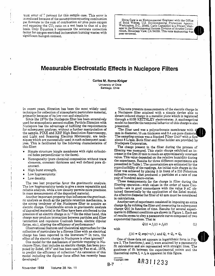
Measurable Electrostatic Effects in Nuciepore FiltersCarlos M. Romo-Kroger
University of ChileSantiago, Chile
In recent years, filtration has been the most widely used This note presents measurements of the electric charge intechnique for collection of atmospheric particulate material, a Nuciepore filter attained with a simple device able toprimarily because of its low cost and simplicity. detect induced charge in a metallic plate which is registeredSince the 1970s the Nuciepore filter has been extensively through a 610B KEITHLEY electrometer. A mathematical
used for atmospheric aerosol studies. Particle filtration with model to describe the temporal behavior of this charge is alsoNuciepore has the advantage of fulfilling the requirements presented.for subsequent analyses, without a further manipulation of The filter used was a polycarbonate membrane withthe sample. PIXE and XRF High Resolution Spectroscopy, mm in diameter, 10 m thickness and 0.4 m pore diamete:and Light and Scanning Electron Microscopy, are tech- The sampling system was a Stacked Filter Unit2 with a flow1niques which are successfully used in such subsequent anal- about 8 L/min. Both filter and filter holder are provided byyses. This is facilitated by the following characteristics of Nuciepore Corporation.this filter: The charge present in the filter during the process of• Simple structure (single membrane with right cylindri- filtering was measured. This static charge exhibited an in-
cal holes perpendicular to the faces). crease in the first 30 min to reach an approximately constant• Homogeneity (pure chemical composition without trace ^ ThjS depended on the relative humidity during
elements, consent thickness and well defined pore di- the T T . °* thrf.dferent "periments areameter, • ^ presented in Table I. The uncertainties are estimated by the' rcproducibility of the readings. An initial nule charge in the
• High burst strength. filter was acnjeved by placing it in front of a 210 Polonium• Low hygroscopicity.' radiative source, that produced a particles at a rate of one• Low density. pair of hundred micro-curies.The two last properties favor the gravimetric analysis. r™"* measurements for the charge in filter during the
The low hygroscopicity tends to give a more reputable and f^' g operatlonTWIth v ues m *f °rder ?f T'r Treliable analysis, while a low density permits more precision ° £! I°.g0,?d ,C0 ordan" ™th ,Val7ue, 9, nC °b:in mass measurement of the deposited material. tamed theoretically by the apphcat.on of the Zebel model.Another important property that influences the gravimet- ^ £0 """ * considered
ric analvsis as much as the particle retention mechanism, is n~~n,~,,~ t • 4 • * j • •the strong tendency of the Nuciepore filter to acquire an r>,±° o l±uu- P,T f 'T " .ImP.?8in*." extraelectric charge. Considerable errors in gravimetric analysis charge Qoby.rubbmg he I'd er and measuring its subsequentofdepositedmaterialinthefilterhavebeenattributedtothe C sev"alpresence of an electric charge in it.- On the other hand, this
exponentialfunctionsatis:forces, etc.), altering the efficiency of performance.3 Q(£) = f\(t) + f2(t) (1)Observational features and theoretical approaches for the wjjh
collection of particulate by a fibrous filter with an electrical n _ _ _charge has been reported in the literature.4-5 In turn, the W> = < exp(-f/r() and QL + Q2 - Q0effect of the electric charge in Nuciepore is often ignored.6 One of these data set appears in logarithmic form in Fig-One model for the mechanism of particle trapping in Nu- ure 2. The functions /i and /, were attained by a parametric
clepore filter, that includes an electric charge, has been pro- flt calculation and are represented with straight lines. Theposed by Zebel, 1974' and has been used by Fan et al;, 1978, goodness of fit between the experimental points and theto predict the efficiency of collection.3 An extension of this theoretical curve f\ + f2 is apparent in this figure.model including the dipolar force effect has recently been ___developed.3 . Copyright 1939 fl n O I I O o o
November 1989 Volume 39. No. 11

APPENDIX C
PYROX 8212 HEAT AND MATERIAL BALANCES
MHI-APPUED\R3S20-09.TBP
\- 1CN 1 S cL o'o co|£ -2 2 §T-
CL
59u.§
• CMK
UJ I-J 1m Q< 3r— KUJ EO 2z .i11 s^ LLCO S
< 1S Ies ?CO 5 «
0 08 £
IS 101 I .1UJ I: g
S| ICO f™ S.co 8.
E CHEMICAL
ERATION SY
earn numbers
corres
£5 *So |Q S z
"s
•M
s
O)T—
CO
-
co
CMT-»
O
o>
r-
«Sg
illo w8l«
<A
"o
S s^"§ * So iS
« «
§5
c
o(A
"*• *" CO 3CO
~* O *"
S c aO D
||||
!2 <u c"5 "55 5C/5 03
lOlzz|O
UJ
wEOw1UJQ
o:t-UJ5/*
III•,r
§O ;in r-->CM; !CO:(O
8i"!
CM
N
ID
§
§
§
§
8
8
8
8
CM
«?
«9
0
-
!
oCM
OCM
CM
*
in
!
i8
89
CO"CM
f—CO
1
03
CMCM
CM
ino"
0
is.
sin
co8S
iso
CO
8"
in
co"
KCM"
ci**
g3?f || I
ICM
CM
CM
O)
CMCO
^
CMt™
O)oS
00
fR
q
•t8
oS
oCO
— £ .C
n S SS 5
o:UJzO fl> '* w
•3 T5 ra•i? S £ 1 IS ra , >; •§,7 w w . S ' n j ' ^
•*tZA;irECiiSi
IS 8
r!IO
ir-.:<o
Nin
toin(D
3
S
i8
Illllill
8osit/jQoM ^ c ° o
O §* <U - "-S3 *-
fo >.5"£ ra"(5 w>
ico"
oCM"
ro ro
i
§
M COin
8j:
3••"
T-
m"CM
gco"
^
88
O)COf:
CM"co
-
8
T(OO
CO
CO
COo
-.
:o
COICOCN 1 *
CM
ioOr"
SISCM CMin
oimr-ICM
in
5
r-coCO
(OCD
CMCM
CM
o"r-
O
is.
Sw
COSi?S
1so
COs8
in
•w"
cc
KCM"
120.000
Illlllffl
wW) ^< '-(3 •§ .2
o O
S c c c SO Q ^ O l O o m ^
o i O z o x < S' : •
LOCOCM

CN>•— ITo jr—CNa
8
CNCM
6
•J O>CQ d£ 3a:O 120)-* -S< Q
3 1CQ 'i. w
y
m "2UJ h- §>t < °co «E §Q 0,3 8.
U- m 2CE T; cm uQ. S |CO r~ i
^ " OJ
Sz II F E
y UJ SV — , J3
2 Q oO » z
15
S
(Nin
m
T
rt
f«.co
S
CO
CO
CNCO
CO
O
7>
i </i c S3< '-5 rau_ o
,2 ^
*" CD
•g = •*^^5
||
•2 ^> ~ 2
CO
Ij
^°lDD "w
(g"-
lit"•
o *"•2 c"§
w in
ID O
w CA
il
1"° Q-S|^ > 852toCOUJO
ARAMETER
0,
&
y
«
U
»
£
tt
rn(T)
^
GO
T"
8
8
]
o
in
o
.0ICN1
w
o
0
o
oN
D_
OT
§
£
1
8*"
*
COCO
oCO
CO1
end
-
CNCT)in
N.Scr
SCN
CC
N.CNCC
8
(*J8in
N
I
CNCDT•<rCN
249,924
1in
.
CNd
~o
CO
CO
SI
COg
ss
— i
J
S? ..J I
1 " . '•'•.'>- UJX
i V
1
.
'
1
T"
1
S
S
^
Kit:in
:5)ffi
CN
CNWin
•o
CCCO
§sI
sCO
nDa_jCOa
Wilsl.E .^ DJ g « _ ^J
CJIOOOCO^S
1 i
" !
1
s\f
sN
feCN
TTtor"
"-
CN8
S
CN
|
ai<i~CO
1
COo"r-
coen
Sen
0
1
75
CN
*
8in
i
COSS
18
g1
If?
^
CN
in
oco"T~
o00
COCN
T;CO
CCCO
(*•
CNO
in"
8
IaenTTCCN
Jlo>
1in
c -ScS «|
godc g?iCJXOZOX<gH-
fsu.Oco.S
IJ tO! CT3
,h=CO
J)3
cxi
I enI QC f,9 ^

APPENDIX D
PYROX 8212 PROCESS FLOW DIAGRAMS
MRI-APPLIED\R3S20-09.TBP D" 1
AR3II237
e HI
i'li r. i..iji KiH!a So£50.
IHI3 g2 c£
COCOCNJF
or
§8 §9, 3

COCsJ
COoren:
31»0
£5f
/\
Ei
/\ /\ /\
0 0 0
sin
gas
aQ!S5
O-3-CM
COor ;
cvj
COCC ,

JI
i ^a tr o 1/7 j . UJ8
i £/\ /\ X\ X\5
3 |fjT-S*i|15s
1 £•<»"83
/i\ /is / N <V\ __ /o\ /CN /i\(%, v - y v 2 / v £ / — g v | y v 5 / v M > '
T __
N
^
•
a'\2•a,a.a-
fs-&f&&
I. kD-
d^E3flS!
£g IS—————————i—————————————————————r———————————— —»————i—————————————————————,—————————
< t
CXJ
CM
CO
jiiigirfi*
i———— - ,
«*.s -UJ I
girt a
2 sir,
CO-=fCM
COor

APPENDIX E
INTERLOCK LOGIC
MRI-APPUEO\R3620-09.TBP E'l
AB3I

INTERLOCK LOGIC
InterlockType1-1
I-2
I-3
I-4
InterlockAction
An 1-1 interlock automatically stops thewaste feed to the TDF. Burneroperation is maintained to maintaindestruction of organics.An I-2 interlock automatically shuts downthe ID fan, burners, waste feed andopens the TRVAn I-3 interlock automatically stopswaste feed and shuts down the kiln andSCC burners.An I-3 interlock automatically stopswaste feed and shuts down the kilnburners.
CausesSee 1-1 Interlocklogic diagram andSection 2.4.3.
See I-2 Interlocklogic diagram andSection 2.4.3.See I-3 Interlocklogic diagram andSection 2.4.3.See I-4 Interlocklogic diagram andSection 2.4.3.
VRI-APPLIEDW3620-09.TBP E"2

:.-.depa.-.~er.:Cata Logger
CCS Cata Low =a?houseCollect-on ——————————————————————————— DifferentialPressure
system Pressure
High Stack CO ' ' High 3tack ;:ox:r loss of ____________ . - _____________ or loss of
signal •
igh Stack ______-- •" .. ____________ . '"I15". afic«."eiccicv •"S3- . 3.cs
12. 13, or 14Interlock
___________ A.sn Ccr.veyorFailure o: both ____________ ' ———————————— ShoppedSCT Burners . ____ T
CCS ControlSystem
__________________ ' " '_____________ Low Kiln"allure cf both .___________| \——————— -——————————— Rotation':<ilr. Burners ' r '
TRV Not • •___________;Closed ——————————~ ;
Stop Wasee Feedsby Shutting Down
————————.——— . , Feed Conveyors
MOTS: fai Trial Burn Plan Table 3-lafor setpoints, averaging.
and cimes associated with interlocks.
•1 Redundant instruments with selection for whichinstrument is controlling. fl D O j I O I. £
—————— -E-3 • —_—-——————— . _

CCS ControlSystem
Emergency shutdown10 Fan Shutdown iTRV will open
II, 13 i 14interlock
Ti-peraturs
Far. Failure,- __________Far. Shutdown ' ' " . ^_________, Electrical Power'
NOTE: See Trial Burn Plan Table 3-lafor setpoints, averaging,
and times associated with interlocks.
AR3M2U7

-~- -r.cerlock Logic
CCS ControlSystem -
Shutdown 3CC *Kiln Burners
II Interlock
MOTE: See Trial Burn Plan Table 3-lafor setpoints, averaging,
and times as$ociated wish interlocks.
E'5 AE3II2U8

~-4 Interlock Logic
^ DCS ControlSvstsm
ShutdownKiln Burners
II Interlock
MOTE: See Trial Burn Plan Table 3-lafor setpoints, averaging,
and times associated with interlocks.

APPENDIX F
OPERATIONAL PHASE STACK TESTINGMETALS AND PARTICULATES
Wni-A?PLIED\R3620-09,APF
AB3I1250
F.1INTRODUCTION
Operational Phase Stack Testing will be performed every three operatingmonths or approximately every 2190 operating hours. Each Operational PhaseStack Test will consist of three runs at one test condition. The testing willprovide stack analysis for particulate and metals. The test will be performed withthe TDF operating on Drake site soils with no additional spiking materials(POHCs, metals or chlorine).
F.2ENGINEERING DESCRIPTION
See Section 2 of the Trial Burn Plan.
F.3OPERATIONAL PHASE STACK TESTING CONDITIONS
F.3.1 NUMBER OF TEST RUNS
Each Operational Phase Stack Test will consist of three test runs at onetest'condition.
F.3.2 OPERATIONAL PHASE STACK TEST CONDITIONS
The Operational Phase Stack Test will be targeted to be performed at ornear the Operational phase operating conditions developed from the Trial Burn(Tables 3-5a and 3-5b) with the exception of chlorine and metals load for whichthere will be no specific target since feed will not be spiked. The followingTables F3-1a and F3-1b provide the Operational Phase Stack Test targetconditions and interlock set points during the Operational Phase Stack Test.
MRI-APPLIED\R3620-09.APF F-P
AB3||251

Table F3-1a. PROPOSED OPERATING AND TARGET CONDITIONS'FOR THE OPERATIONAL PHASE STACK TEST3
Process Parameter
CLASS A OPERATING PARAMETERS
Maximum Solid Waste Feed Rate (Ib/hr)
Maximum Kiln Pressure (in WC)
Minimum Instantaneous Kiln Temperature (°F)
Minimum Hourly Average Kiln Temperature (°F)
Minimum SCC Temperature (CF)
Minimum Differential Pressure Across theBaghouse
Minimum Flow Rate of Scrubber Water to thePacking (gpm)
Minimum pH of Scrubber Water
Maximum Instantaneous Carbon Monoxide in theStack Gas <ppmv)
Maximum Hourly Average Carbon Monoxide in theStack Gas (ppmv)
Maximum Stack Velocity (fps)
NOX (ppmv)
Stack Test MaximumOperating Condition"
Stack TestTarget
Condition
124,000°
-0.1
1000
1100*
1700*
1 in WC
450
6.0
500
100
609
300
120.000d
-0.1
1000
12001
18001
1 in WC
450
6.0
500
100•
55"
300
CLASS B OPERATING PARAMETERS
Maximum Chlorine Feed Rate (Ib/hr)
Maximum Total Dissolved Solids of Scrubber .Water (spec, grav.)
Metals
3001
1.09(at 85°F)
See Table F3-1b
N/A
1.09(at 353F)
See Table F3-lb
CLASS C OPERATING PARAMETERS
Burner Settings
Maximum Quench Tower Discharge Temperature(°F)
Not applicable
500
Not applicable
500
3 All details on timing, delays, and averages are as presented in Table 3-1 a of the Trial Burn Plan Section 3.b Interlocks will be set at the Class A Maximum Operating Condition Points.c 3.5 percent above Stack Test target.a- Average of the mean waste feed rate of the trial bum test tuns.' 100°F less than the Stack Test target.1 Average of the mean temperature of the trial burn test runs.9 5 fps greater than the Stack Test target." Average of the mean velocity of the trial bum test runs.' Average of the mean chlorine feed rate of the trial bum test runs.
Mfll-APPLIED\R3620-09.APF
&R3I1252

Table F3-1b. PROPOSED OPERATING AND TARGET CONDITIONS FOR METALS FEED INTHE OPERATIONAL PHASE STACK TEST
Process Parameter
Noncarcinogenic Metals(Ib/hr)Barium
SilverMercury
Lead
Antimony
ThalliumCarcinogenic Metals(Ib/hr)
Arsenic
Chromium
Cadmium
Beryllium
Operational Phase Stack TestMaximum Operating Condition
Not Applicable
Not ApplicableNot Applicable
Average Lead feed rate in the trialbum test runs
(estimated to be 1 00 Ib/hr)Not Applicable
Not Applicable
Average arsenic feed rate in the trialbum test runs
(estimated to be 1 6 Ib/hr)Average chromium feed rate in the
trial burn test runs(estimated to be 10.4 Ib/hr)
Average cadmium feed rate in thetrial burn test runs
(estimated to be 2.4 Ib/hr)
Average beryllium feed rate in thetrial burn test runs
(estimated to be 0.5 Ib/hr)
Operational Phase StackTest Target Condition
Not Applicable
Not ApplicableNot Applicable
Not Applicable
Not Applicable
Not Applicable
Not Applicable•
Not Applicable
Not Applicable
Not Applicable
MRI-APPLIED\R3620-r>9 APe F-4
AR.3II 253

F.3.3 WASTE FEED CHARACTERISTICS
The waste feed to the TDF during the operational phase stack testing'wilbe site material. The material is expected to have low heating value(< 250 Btu/lb) and high ash content (> 80% ash).
F.4OPERATIONAL PHASE STACK TESTSAMPLING AND MONITORING PLAN
F.4.1 SAMPLING AND MONITORING LOCATIONS
Stack.gas and waste feed sampling will be conducted during theOperational Phase Stack Test, corresponding to sampling points S1 and S4 inFigure F4-1 (S2 and S3 will not be sampled as part of the operational phasestack tests).
*
F.4.2 SAMPLING AND ANALYSIS PROTOCOLS
Table F4-1 provides the sampling and analysis methods to be used in theoperational phase testing. The stack sampling and feed sample practicalquantitation limits are shown in Table F4-2.
,'nl-APPUEO',a3S20-09.APF
AR3I I 251*

eno2oc'o
XOQC>•a.V*—o
SO)to'•5u
0)£UCO
it
0)3en
ecaa.
F-6
AR3I1255

C/5
LU CCC/5 Q.
Q. C/3
li£<D. CJO z
4 Su. <0> C/3
I Analysis
1 Method
•oo£"3sc,o*2aI"Q.
_ W
II
1 2<l
•aoOJ
0)Q.
reCO
= 1a.§S o-n cucot
JBQ.
n(0
o0o
life"< CD ° 03
'oSg « |
w
O^oc ino o
V= COCO |Q) 1.SP <"
It!
o .0 J .2 -|
•m S2 <u co S•§ < CQ O O _J5
oin.___
o "5..Q. W
§1CO 0)
C 0) §0 ™ tj u.
E c- o Q.w 'p °- JJ-0 o -2 °-o1 ! «2 (D "t/5 Q)6 s a§
. "5.
Iiui CO(D~ cu0 Q,c LL
— , _ .
O CO QJ G) O— ^ — ' CD CO C "D
fQ.UJ »*" CMC ' O
11Ii< Q
o § | I
03 i— (D CO -C m"Z < 03 O O _j5
in
Gravimetric
(EPA Method
Co1.0'tocuQ
CO_cu
.0CBQ.3£
, ra52O
|
•Q. _LU S^coCM0 "g0 J
o i
O)CM
1Q) CO
kU «•»
Q i
(DQ.
'S5
c8 1CO 1
COco0ua&
<S
F-7
AR3N256

Table F4-2. PRACTICAL QUANTITATION LIMITS FOR METALS BY ICAP
MetalAsBeCdCrPb
Stack samples3(yg/dscm)
57.3
0.334.57.545.3
Feed samples(mg/kg)
50.5
0.5
57.5
a Practical quantitation limits were estimated to be 3 times the iCAP methoddetection limits given in EPA Draft Method 29.
MRI-APPUEDVRSSCOO-.A.-r F-8
AR3I1257

F.5OPERATIONAL PHASE STACK TEST
SAMPLING PROCEDURES
F.5.1 STACK EMISSIONS TESTING
The stack gas sampling will be performed according to EPA Draft •Method 29 using a Modified Method-MM sampling train for multiple metals andtotal particulate matter emissions.
\
F.5.1.1 MM5-MM Sampling Train for Metals and Particulate Matter
The sampling method for metals in the stack emission will be the same aspresented in Section 5.1.2 of the Trial Burn Plan, except that the particulatematter emissions will also be determined using the MM5-MM sampling train.According to the procedures in EPA Draft Method 29, the probe nozzle, probeliner, and all glassware up to and including the front half of the filter holder willbe rinsed with acetone prior to the front-half rinse with nitric acid. The acetone'rinsates and the filter will be submitted for particulate determination prior tometals analysis.
F.5.1.2 Oxygen and Carbon Dioxide Sampling
The sampling method for O2 and C02 will be the same as presented inSection 5.1.4 of the Trial Burn Plan, and will utilize the MM5-MM train forcollection of the gas samples for Orsat analysis.
F.5.2 FEED SAMPLING
Feed sampling will consist of sampling from the feed belt. The samplingwill be performed by taking a ~ 100-g grab sample every 30 min and combiningall the grab samples into a single composite sample. The composite will beanalyzed for total metals (arsenic, beryllium, cadmium, chromium and lead).
MRI-APPLIED\R3S20-09.APF ' F"9
A R 3 1 I 258
F.6OPERATIONAL PHASE STACK TESTSAMPLE HANDLING AND ANALYSIS
F.6.1 METALS EMISSION SAMPLES (MM5-MM)
Figure F6-1 presents a schematic of the analytical scheme for the metalsand particulate samples from the MM5-MM train. This schematic differs fromthat presented in Figure 6-2 in that the additional front-half acetone rinse and thefilter will be used to determine particulate emissions prior to submittal for metalsanalysis. The particulate matter emissions will be determined from these twosamples according to the procedures in Section 6.2.3 of the Trial Burn Plan. Thesamples from the metals sampling train will be digested and analyzed for metalsas shown in Figure F6-1 and described in Section 6.2.6 of the Trial Burn Plan.
F.6.2 OXYGEN AND CARBON DIOXIDE ANALYSIS (ORSAT)
The analysis method will be same as presented in Section 6.2.5 of theTrial Burn Plan.
F.6.3 METALS ANALYSIS OF FEED SAMPLES
The metals analysis of feed samples will be the same as presented inSection 6.2.6 of the Trial Burn Plan.
MRI-APPUED\H3620-09.APF F"1Q
AR3II259

CD
<3J no>o
11o'
«C\J
co <DC O)OJ C
OI^ '——' - § S, 3 I* .o
ci!nI
® CO C3isig51="O CO •;CD 0> «
~ O
15:fac ....
cucoQ.
ro
CDs: toCO C
C
£§
20)
0)UCO
or___________________ __COc
co _ ,„ w ^ j
o o"0) Ii
Ii
IE
<D COc wC Q)II> Q0> i_O (135 coTJ >?'iCC
COCD ,——i _ O .2 .® ____ U-
0)3CD
oO
0)
iZ
2ISo'toCO
j=
I
CD
o .235II
o
II>>
£a
cc
F-11
A R 3 I I 260

F.7OPERATIONAL PHASE STACK TEST
REPORTING OF RESULTS
F.7.1 REPORT FORMAT
Test results will be reported within 30 to 45 days after completion ofsampling. The following is an outline of the Operational Phase Stack TestReport.
1.0 Introduction
2.0 Incinerator Operating Conditions
3.0 Test Resultsi3.1 Stack Results •
3.1.1 Metals Emissions3.1.2 Particulate Matter Emissions
3.2 Feed Total Metals Results
4.0 Quality Assurance Report
AppendicesAppendix A—Field Sampling Data and Sample TraceabiiityAppendix B—Process and Feed Rate DataAppendix C—Modified Method 5 CalculationsAppendix D—Metals Analysis'ResultsAppendix E—Calibration Data
MRI-APPUED\H3S20-09.APF . F'12
&R3II26I

F.7.2 INCINERATOR OPERATING CONDITIONS
Incinerator operating conditions will be reported as follows:
Incinerator Operating Conditions
ConditionSolid Waste FeedRate (Ib/hr)Kiln Temperature(°F)SCC Temperature(°F)pH of ScrubberWaterStack Velocity .(fps)
Run 1Mean
Run 2Mean
Run 3Mean
Average ofthe Means
In addition any waste feed shutoffs and the cause of those shutoffs will bereported.
F.7.3 TEST RESULTS
F.7.3.1 Stack Results
Stack results will consist of particulate concentration (grains/dscf)corrected to 7% oxygen as shown in Appendix B of the Trial Burn Plan, andemission rates of arsenic, beryllium, cadmium, chromium and lead in g/hr.
F.7.3.2 Feed Total Metals Results
Feed total metals results for arsenic, beryllium, cadmium, chromium, andlead will be reported in mg/kg and input rates calculated in g/hr.
MRI-APPLIED\R3620-09.APF F'13
AR3M262
F.7.4 QUALITY ASSURANCE REPORT
AThe QA Coordinator will prepare a QA report summarizing the results of ^|Fall audits conducted and assessing the quality of the data relative to theobjectives set forth in Table 14-2 of Vol. II that pertain to metals analysis ofwaste feed samples and to particulate and metals analysis of stack samples.This report will be included in the Operational Phase Stack Test Report:
M=ii-APPUED\R3620-09.APF ' F"14
AR3I I 263

APPENDIX G
RISK BURN TESTING PROCEDURES
MRI-APPUSffiR3S20.09.APG
AR31 (26U.

G.1INTRODUCTION
The Risk Burn will be performed to provide information to USAGE toconduct direct and indirect risk analysis. The Risk Burn will provide informationon stack analysis, fly and bottom ash and scrubber water when the TDF isoperating on Drake site soils with no additional spiking materials (POHCs ormetals).
G.2ENGINEERING DESCRIPTION
See Section 2 of the Trial Burn Plan.
G.3RISK BURN CONDITIONS
G.3.1 NUMBER OF TEST RUNS
The Risk Burn'will consist of three 3-hr test runs at one test condition.
G.3.2 RISK BURN TEST CONDITIONS
The Risk Burn will be targeted to be performed at the same targetconditions as the Trial Burn (Tables 3-5a and 3-5b) with the exception of chlorineand metals load for which there will be no specific target since feed will not bespiked. The following Tables G3-1a and G3-1b provide the Risk Burn targetconditions and interlock set points (i.e., maximum operating condition) during theRisk Burn.
MRI-APPLIEDVR3620-09.APG G-2
AR3II265

Table G3-1a. PROPOSED OPERATING AND TARGET CONDITIONSFOR THE RISK BURN3
Process Parameter
Risk BurnMaximum Operating
Condition"Risk Burn
Target ConditionCLASS A OPERATING PARAMETERS
Maximum Solid Waste Feed Rate (Ib/hr)Maximum Kiln Pressure (in WC)
Minimum Instantaneous KilnTemperature (°F)Minimum Hourly Average KilnTemperature (°F)Minimum SCC Temperature (°F)
Minimum Differential Pressure Acrossthe Baghouse
Minimum Flow Rate of Scrubber Waterto the Packing (gpm)
Minimum pH of Scrubber WaterMaximum Instantaneous CarbonMonoxide in the Stack Gas (ppmv)
Maximum Hourly Average CarbonMonoxide in the Stack Gas (ppmv)Maximum Stack Velocity (fps)
NOX (ppmv)
124,000
-0.1
1000
1100
1700
1 in WC
450
6.0
500
100
60
300
120,000
-0.1
1000
1200
1800
1 in WC
450
6.0
500
100
55
300
CLASS B OPERATING PARAMETERS
Maximum Chlorine Feed Rate (Ib/hr)
Maximum Total Dissolved Solids ofScrubber Water (spec, grav.)
Metals
330
1.09(at 85° F)
See Table G3-1b
N/A
1.09(at 85°F)
See Table G3-1bCLASS C OPERATING PARAMETERS
Burner Settings
Maximum Quench Tower DischargeTemperature (°F)
Not applicable
500
Not applicable500
a All details on timing, delays, and averages are as presented in Table 3-1 a of the Trial Burn PlanSection 3.
b Interlocks will be set at the Class A Operating Condition Points.
G"3
AR3II266
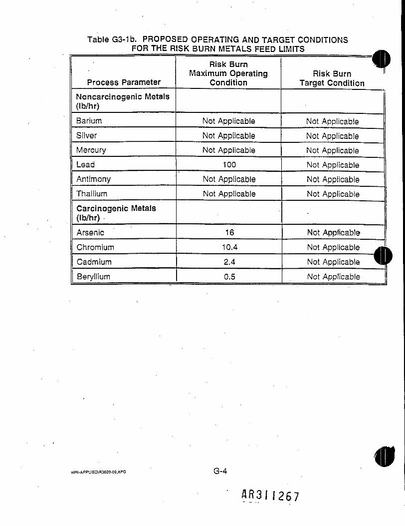
Table G3-1b. PROPOSED OPERATING AND TARGET CONDITIONSFOR THE RISK BURN METALS FEED LIMITS
Process ParameterNoncarcinogenic Metals(Ib/hr)BariumSilverMercuryLeadAntimonyThalliumCarcinogenic Metals(Ib/hr)ArsenicChromiumCadmiumBeryllium
Risk BurnMaximum Operating
Condition
Not ApplicableNot ApplicableNot Applicable
100Not ApplicableNot Applicable
1610.42.4
0.5
fRisk Burn ^Target Condition
Not ApplicableNot ApplicableNot ApplicableNot Applicable |Not Applicable |Not Applicable j
Not Applicable [Not Applicable jgNot Applicable ™Not Applicable
MHI-APPUED\R3620-09.APG G"4
AR3II267
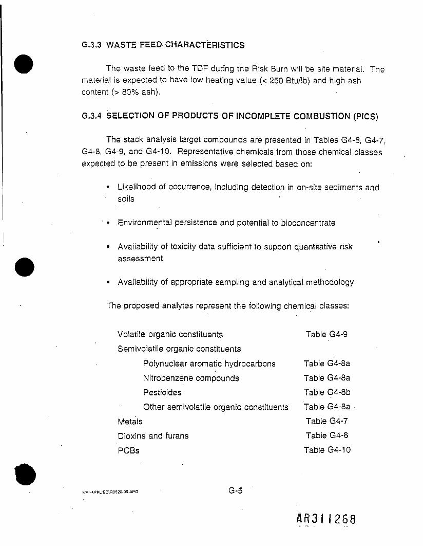
G.3.3 WASTE FEED CHARACTERISTICS
The waste feed to the TDF during the Risk Burn will be site material. Thematerial is expected to have low heating value (< 250 Btu/lb) and high ashcontent (> 80% ash).
G.3.4 SELECTION OF PRODUCTS OF INCOMPLETE COMBUSTION (PICS)
The stack analysis target compounds are presented in Tables G4-6, G4-7,G4-8, G4-9, and G4-10. Representative chemicals from those chemical classesexpected to be present in emissions were selected based on:
• Likelihood of occurrence, including detection in on-site sediments and• soils
• • Environmental persistence and potential to bioconcentrate
• Availability of toxicity data sufficient to support quantitative riskassessment
• Availability of appropriate sampling and analytical methodology
The proposed analytes represent the following chemical classes:
Volatile organic constituents Table G4-9Semivolatile organic constituents
Polynuclear aromatic hydrocarbons Table G4-8aNitrobenzene compounds Table G4-8aPesticides Table G4-8bOther semivolatile organic constituents Table G4-8a
Metals Table G4-7Dioxins and furans Table G4-6PCBs Table G4-10
MR'-APPLIED\R3620-09.APG
AR3II268

G.4RISK BURN
SAMPLING AND MONITORING PLAN
G.4.1 SAMPLING AND MONITORING LOCATIONS
Sampling will be conducted for stack gas, bottom ash, fly ash, andscrubber water during the Risk Burn, corresponding to sampling points S2-S5 inFigure G4-1.
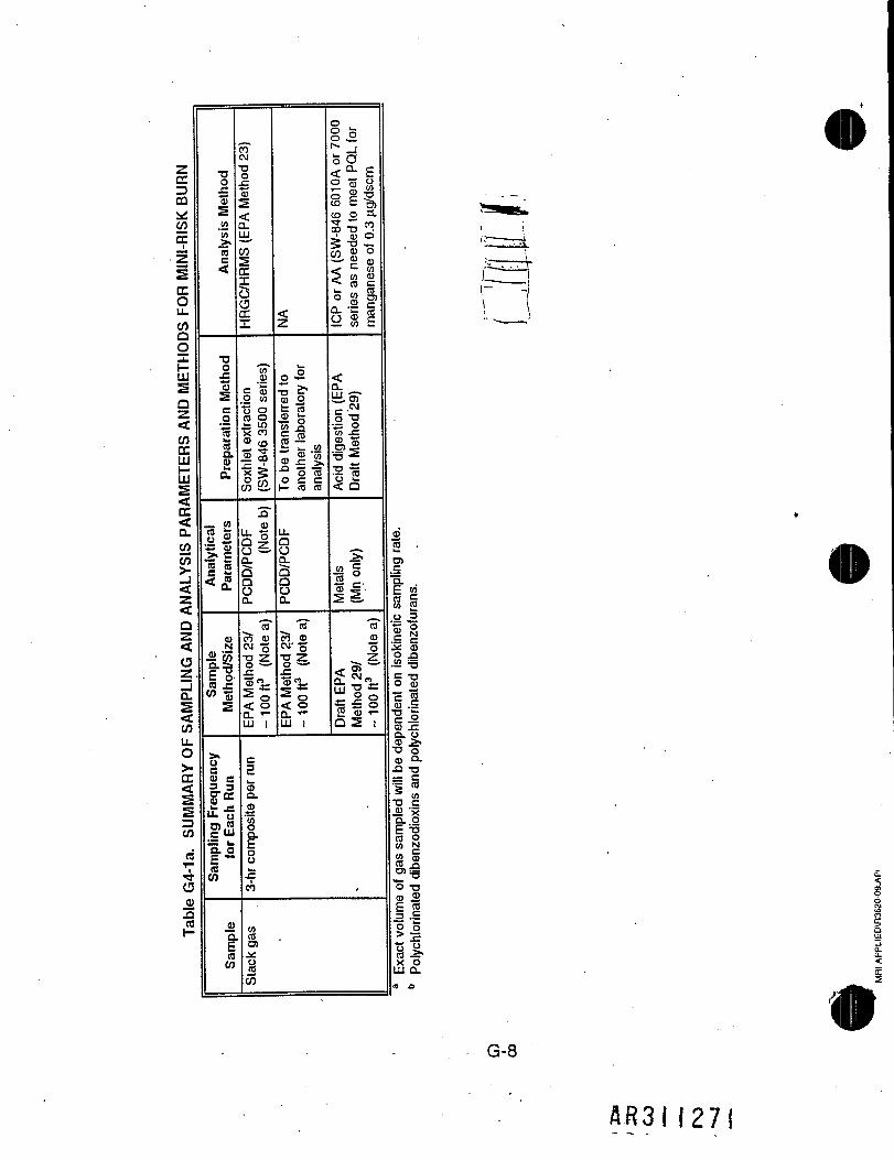
About 1 month prior to the Risk Burn an abbreviated test will be carriedout, which is referred to as a Mini-Risk Burn (MRB). It will consist of two 3-hrruns for PCDD/PCDF and one metal (manganese), as shown in Table G4-1a.
G.4.2 SAMPLING AND ANALYSIS PROTOCOLS
Table G4-1b summarizes the sampling and analysis methods to be usedin the Risk Burn. In the Risk Burn the waste feed will be sampled and analyzedby OHM in accordance with the normal daily procedures included in theChemical Quality Management and Sampling Plan (CQMSP). A summary of thatsampling and analysis is shown in Table G4-1c and the analysis results, whichwill be reported separately by OHM, are listed in Table G4-1d. Tables G4-2through G4-10 show the compounds to be analyzed in all other samples and theestimated practical quantitation limits (POL). These tables include most, but notall, of the compounds that were included in the Risk Assessment for the DrakeSuperfund site. All compounds could not be included because of limitations inavailable sampling/analysis methods. Table G4-11 presents those compoundswhich are in the Risk Assessment but not in the Risk Burn.
*MRI-APPUED\R3620-09.APG G-6
AR3II269

F5HVi •a3oCO
*
cu<*-•en>»eni_ot-ieni_o'o_cXO
xsOJ«'•5orocuj=u
CJ
O)IT
£ s«£T tn c iw c 5 |03 o f Pen fi- mco en •=cvT = oco £•£ si-~ cu .co « §
G-7
AR3II270
zCC13CO^COCCtz2CC0u_COQoXIDs0z<COCCLUUJ:E><CC<
ALYSIS P
<oz<0z.
SAMPLI
LL0>•CC<smIDCO
dT-
4GQ)xt.2
TIO£"Ss.2in_>.nc<
•ao
eparation Mel
a.
_ w
Analytica
Parameter
oN
Ji «11.*i>>UC<u e3 3c?01it •=LL o
?L3
|o(BCO
_4)
nCO
COOJT30
f5<Q.UJ_
CO5a:XbaQCX
"t/T03
ilet e
xtraction
-846 3500
seri
IIS"en
CDD/PCDF (Noti
Q.
15"?5 03CM "5
I~|«:• o< oQ. *-LU I
<z
o£
le tr
ansferred 1
her laboratory
ysis
-" o «o e c1— (0 (0
CDD/PCDF
CL
"nTc<5 <ow-5"o §•i s• o^2LU 1
0
§ £»s<a E0 03 ^° Ifw E -9,(D O if *" mto -a ".
." 03 O5 "0 —w S °— ' £ 03<• c M
< S ik_ ,. OJO W O)Q) f-o« ii=i w c
<0.ty.srI'iin J=
*i•o ll< Q
S
1103 £'5§.
1?03"oZ
<r &>£ ™r,
|H« 03 T-Q2 !
C3i.03Q.03
1
IOUw.Cim
mCO01±iU«55
2'«u.O>
"5.E <2S |o 303 9c CJ£ 030 _Q."e TJ
aendent o
chlorinate
-S —•a o<D Q.ja -a= c5 *1 SJ2 'xe-.SE T3(B 0W N2 §S>^a_o>^0 TJ§03
CO3 .£
§ °* JTQ £CO ^X 0LU a.n J3
G-8
A R 3 I 1 2 7 1

3
rsis P
ROTOCOI
2<<Qz<oz_1CLs<CO
CCDCQ*COCC
.Q1rfo0).0£
•Do£'SS<fl'M
<
TJn
1 Preparation Methi
| Analytical Parameters
•§£o_J3Q.
(0CO
>.
Frequenc
U)c"5.raCO
03a
"o"
per CQMSP
(See Table ,G4
-per CQMSP
TJCOCJ1•<»•O
85 JiIS-o "°ili
/>5P
cuCL
5gl-2 8'22 0 03S,8£co co .c
II-= 1 SS5?C >- 0I-"§ c £co o —CO TJ 3
0303Li-CU
1^
Ocos
GC/MS SW846
TJCO 5"
I.S= i2 5co W0) ~CL Q.tn <UQ 1-
0)cu ^CO c-vj¥S•- cu« s0£
03CL
^ic~ <"s^52.5,CL cn§sCO 1
cE a°1^£•§-.§ §:03 0 .-03 0) "O-rE 'c ^
01 "D =
S = '=CO CO .
&8.-I03 C ;f— W
6 8 <
S? c"S ffl Jc « %5 5 f
lie:0 0 C/
0r -CJ00
1 GC/MS SW846
J Solvent Extraction
(SW846-3540)
Semivolatiles (Se
e Table
[G4-3)
.22cn>>
pin
niiu a
>s for
anal
0 -s13 9-
^ 032 a3-co5 S-0 CO
ni003}
5CO
.i
HRGC/HRMS v
(5-Naphthylarnine
1 GC/ECD
I SW846-8151
w5COT00
CO5 •Q.
03.Q.203CUCO,
¥T3!y _-S T03 •<3-x a
< co <o -g »S
«£ 0 Q) -1- J
?II|1a. > N < gyio oo «
EPA 1311
extr
action
.Acid di
gestion per
SW846-3010A/3020A
0)xi£0303CO,cnS'S!2i<?°-3
I HRGC/HRMS
SW846-8290
ocnCNJopCDf1COcuQ.
0303CO,CO
1|CDCO tin 0.= CD
13
ocoeg00
GC/MS SW846-
Dispersion Purge and
Trap (SW846-8260)
0303 _ .<o. cysci.2 30^
03CL
s C/3§.nCOCO, g,
CL "5)
§sCO 1
cS (D
j every 30
} composil
B.EEK ,CO . JCO TJ :•s5'fo infeo.c £.5 oO o
«<_>.i.
o !Is- fsCM 1 =00 ICV)
GC/MS SW846-
HRGC/MS
with :
Solvent Extraction
(SW846-3540)
Semivolatiles (Se
e Table
G4-3)
P-Naphthylamine
cnis-
O fO2 §E o5_ c":o.s>5I— CQ= i*S 03
||
o cn
GC/ECD
SW846-8151
55CD•*CO
COd
Herbicides (S
ee Table
G4-4)
< cn <° -g °>S<§ % s?»Mli0. > § ga w 00^2.
EPA
1311
extraction.
Acid digestion pe
rSW846-3010A/3020A
CD
I0303CO,
CO
1
i<?
^S
'
HRGC/HRMS
SW846-8290
ocnCNCOCO• ~CO
CO5o_OJ01CO,CO
coLL2 CD-S' *co a•i-sis
0i »N. X
ICP or AA
SW846-6010AO
series. CVAA
fo
(SW846-7470A)
coS
EPA
1311
extraction.
Acid
digestion per SWl
3010A/3020A
<D
10303W,
CORJ0)2.
i*r^3
o.S03CL
CO
SE§ S£scu oCU TIm Ol&LdE o |CO TJ *-••a-2 S.S? co „,-8.1g E E0 8 S
w.03
S -3 B .* nl0 .2CO 5
soIUJ_lQ.G_<
LT
G-9
AR3II272

IIao
4a
TJ3
D;.2n5
2i|ISi»S.0)LB
(A037i3Eh.(S
Analytical
^
103CL
i
o0)
1LL.O)="a
i
a>"3ERCO
£
Gravimetric (EP
Method 5)
2
Desiccal
Particulate
^CLCO
| Ion
Chromatogr
z
CM
O
oin§n
£ o03 °^ 7
|tn
03Q.
S
1CO
oo '"" "E0 O _
ICP or GFAA
SW846-6010A(
series. CV
AAf
(SW846-7470A]
1.
¥IffTJ OTJ £
33
"CO*ro
• 03n
.22 CO 03-fl) 03
cn"CM
•£
o
D i
c
10)CL03
1U
CO
IC/PCR
(BIF Guidance)
entration
idance)
" 3o 0Sti:eta
§3"r£ 40 O
Hexavalent
(See
Table
'S^
m i
c3
In
03CL03
1
£CO
CO~
C333CO
SiC3 CO
5
1'S03
TIJIc<0
o _ -S<N 03 .
J | |0
11o"T—§1
IIsQ. .03'35oCL
1CO
uiiCD COD
CO 3
gS-— .CO -t-03 C3TJ U5
j£ i
en"4
o O
ii73 a>
<o2 S
VOSTT
SW846-
'SCLic1o73
tCL
OU_
n COb coD 2
§ Oco a
c3.I?03 0TJ in
IiIi_^0
S03£1
S g5 co
?0
II
VOST T
SW846-
^
8.cEoOJ
73
II03 " "
11
COCM
15
5CO
3
COCM
o!
03CL
^__CD
cn 4i ®
DioxIns/Fur
(See Table
COCM
Method
c
1SCL03
composit
CO
3—5
5COS g
COCM
|
03•sTJ03
1
o"™
4a_03
n *^W
COCM
0
'Z
8.
|1sa.03'35|i£CO
s33a.
103
u.03CL
cfCO
03
C_o'cu
"81
CC*5j*>q snonur
cC
<
•§cnCM 3
2 .0 £
i|Sin in °>
O 0 2
0
X
z8ac_otoTJ
750)
XOJD
§
1O
cnCO0OCOCO
<E
G-10'
AR3II273

to
L METHOD
<•Op_J<<QZ<CDUJQ.
tUJ_laS<COLLO>-CC<s2Z)CO•o4aoJ2.2
a.COSaoCCLLJa.QLLJUJLLHICO
§CCoLL
TJO
"32
Analytica
(/)0)CO_>,CO
<
CUCL>>Hju"5.ECOCO
inoCMQ2CO<
3m
"5COTJ0303LLi__O
"203
'o
•* COr-- h-CO COQ Q
££CO CO< <
c037z co11w °< 2
^ ^
s'55oCLEoO£COQ
o"CO
ro"COor-d§oTo03D3TJOinoCO<Q.LU
"cnS032"c5
£
ooCO£'1k_o_«"'co>.cocCOoO3oh-TJCO
CMS.S20 C33 CO
I-- CO
~cou'cCOD3
o_CD
75
emivo
CO
or>-CMCOoininCO<Q.LU
03
CO>1.C
CLCO
ca.
co2co"5oCO2cnIc _•B v>§ 50 fe^02ri2JO nj
•5.<CO Q.O LU
UCO
03LL.
OCOCMCD
0OTOJCOx:
0 digestion wil
2.2in co<r —2 §LU co
7§COBOJO
"CO£
o"^§r- So f-CM TJin cr coo" o"cn rT- TJ-!~~ r~-£ 0•> CO> 0c _O ^j.To CM03 Tfcn r-10 o- coCO f .2^ - £.' - O ^£>> in coQ- O3 CLU r co
S_coJOT52ig
.cj?<TJCD_N15COCO
TJiTfOCD_Q
|2_cTJ03
"STJ03cocn03•s.COccoo'c3CDCLCO
G-11
&.R3I I27U
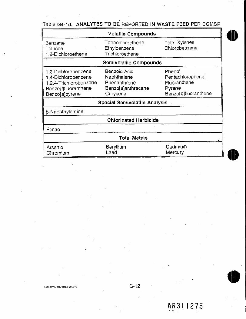
Table G4-1d. ANALYTES TO BE REPORTED IN WASTE FEED PER CQMSP
Volatile CompoundsBenzeneToluene1,2-Dichloroethene
Tetrachloroethene Total XylenesEthylbenzene ChlorobenzeneTrichloroetheneSemivolatile Compounds
1,2-Dichlorobenzene1,4-Dichiorobenzene1 ,2,4-TrichlorobenzeneBenzo[/]fluorantheneBenzo[a]pyrene
Benzole Acid PhenolNaphthalene PentachlorophenolPhenanthrene FluorantheneBenzo[a]anthracene PyreneChrysene Benzo[b]fluoranthene
Special Semivolatile Analysis(3-Naphthylamine
Chlorinated HerbicideFenac
Total MetalsArsenicChromium
Beryllium CadmiumLead Mercury
Mai-APPLIED\R3620-09.APG G-12
AR3II275

Table G4-2. VOLATILE ORGANIC ANALYTES IN ASH SAMPLES
CompoundChloromethaneBromomethaneVinyl ChlorideChioroethaneMethylene ChlorideAcetoneCarbon Disulfide1,1-Dichloroethene1,1-Dichloroethanefrans-1 ,2-DichloroetheneChloroform1 ,2-Dichloroethane2-Butanone1,1,1 -TrichloroethaneCarbon TetrachiorideVinyl AcetateBromodichloromethane .1 ,1 ,2,2-Tetrachloroethane1 ,2-Dichloropropanef/ans-1 ,3-DichIoropropeneTrichloroetheneDibromochloromethane1,1,2-TrichloroethaneBenzenec/s-1 ,3-Dichloropropene2-Chioroethyl Vinyl EtherBromoform2-Hexanone4-Methyl-2-pentanoneTetrachloroetheneTolueneChlorobenzeneEthylbenzeneStyreneTotal Xylenes
Estimated PQL(ug/kg)
101010105-10055555551005550555555551055050555555
Mfil-APPLIED\R3620-09.APG
AB3! I 276
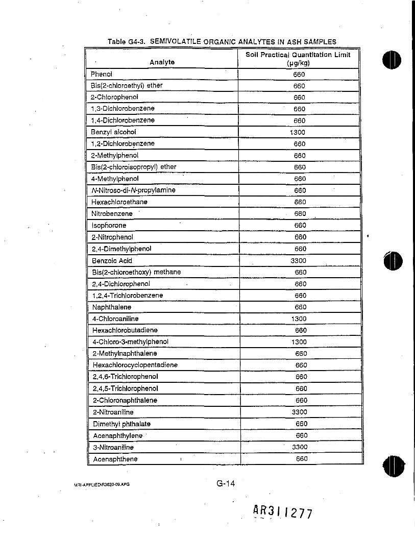
Table G4-3. SEMIVOLATILE ORGANIC ANALYTES IN ASH SAMPLES
AnalytePhenolBis(2-chloroethyl) ether2-Chlorophenol1 ,3-Dichlorobenzene1 ,4-DichlorobenzeneBenzyl alcohol1 ,2-Dichlorobenzene2-MethylphenolBis(2-chloroisopropyl) ether4-MethyiphenolA/-Nitroso-di-/V-propylamineHexachloroethaneNitrobenzeneIsophorone2-Nitrophenol2,4-DimethylphenolBenzoic AcidBis(2-chloroethoxy) methane2,4-Dichlorophenol1 ,2,4-TrichlorobenzeneNaphthalene4-ChloroanilineHexachlorobutadiene4-Chloro-3-methylphenol2-MethylnaphthaleneHexachlorocyclopentadiene2,4,6-Trichlorophenol2,4,5-Trichlorophenol2-Chloronaphthalene2-NitroanilineDimethyl phthalateAcenaphthylene3-NitroaniIineAcenaphthene '
Soil Practical Quantitation Limit(ug/kg)660660660660
6601300660
660660660
660660
. 660
660
66066033006606606606601300660130066066066066066033006606603300660
MRI-APPUED\R3S20-09.APG G'14
flfc3||277

Table G4-3 (Continued)
Analyte2,4-Dinitrophenol4-NitrophenolDibenzofuran2,4-Dinitrotoluene2,6-DinitrotolueneDiethyl phthalate4-Chlorophenyl phenyl etherFluorene4rNitroaniline4,6-Dinitro-2-methylphenolA/-Nitrosodiphenylamine4-Bromophenyl ph'enyl etherHexachlorobenzenePentachlorophenolPhenanthreneAnthraceneDi-n-butyl phthalateFluoranthenePyreneButyl benzyl phthalate3,3'-DichlorobenzidineBenz[a]anthraceneBis(2-ethylhexyl) phthalateChryseneDi-n-octyl phthalateBenzo[fa]fluorantheneBenzo[/fjfluorantheneBenzo[a]pyrenelndeno[1 ,2,3-cc/]pyreneBenzo[g,/v]perylenep-Naphthylamine
Soil Practical Quantitation Limit(pg/kg)3300
3300
660660
660
66066066033003300660
660
6603300
660
660660660
6606601300660660660660660660
• 660660660
55
MRI-APPUEDVR3S20-09.APG ' G"15
A.R3II278

Table G4-4. HERBICIDE ANALYTES IN ASH SAMPLES
Compound2,4-D
2,4-DB
2,4,5-T
2,4,5-TP
DalaponDicamba
DichloropropDinoseb
MCPA
MCPP
FENAC
Soil PQL(ng/kg)804
610
134
114
3,886
181
436
47
166,830
128,640'
1,000
Table G4-5. TCLP METAL ANALYTES IN ASH ANDSCRUBBER WATER SAMPLES
CompoundArsenic
BariumCadmium
ChromiumLeadMercury
SeleniumSilver
Soil Estimated PQL(ng/L)
2.1 (by GFAA)
1.24.5
10.5
4.2 (by GFAA)0.3 (by CVAA)
3.9 (by GFAA)
8.1
Water Estimated PQL(ng/D
2.1 (by GFAA)
1.2
4.5
10.5
4.2 (by GFAA)
0.3 (by CVAA)
3.9 (by GFAA)
8.1
MR|.APPLIEO\R3620-09.APG G - 1 6
AR3II279

Table G4-6. DIOXIN COMPOUNDS PQLsa AND TEFsb, IN ASH SAMPLESAND STACK SAMPLES
m
Compound
2,3,7,8-Tetrachlorodibenzo-p-dioxin
1,2,3,7,8-Pentachlorodibenzo-p-dioxin
1,2,3,4,7,8-Hexachlorodibenzo-p-dioxin
1,2,3,6,7,8-Hexachlorodibenzo-p-dioxin
1,2,3,7,8,9-Hexachlorodibenzo-p-dioxin
1,2,3,4,6,7,8-Heptachlorodibenzo-p-dioxin
Octachlorodibenzo-p-dioxin
2,3,7,8-Tetrachlorodibenzofuran
1 ,2,3,7,8-Pentachlorodibenzofuran
2,3,4,7,8-Pentachlorodibenzofuran
1,2,3,4,7,8-Hexachlorodibenzofuran
1,2,3,6,7,8-Hexachlorodibenzofuran
1,2,3,7,8,9-Hexachlorodibenzofuran
2,3,4,6,7,8-Hexachlorodibenzofuran
1,2,3,4,6,7,8-Heptachlorodibenzofuran
1,2,3,4,7,8,9-Heptachlorodibenzofuran
Octachlorodibenzofuran
TEF
1
0.5
0.1
0.1
0.1
0.01
0.001
0.1
0.05
0.5
0.1
0.1
0.1
0.1
0.01
0.01
0.001
Estimated PQLC
Ash(ng/kg)
5
25
25
25
25
25
50
5
25
25
25
25
25
25
25
25
50
Stack(ng/dscm)
0.013
0.067
0.067
0.067
0.067
0.067
0.13
0.013
0.067 ,
0.067
0.067
0.067
0.067
0.067
0.067
0.067
0.13
a PQL is practical quantitation limit. Assumes a 10-g sample (or 3 dscm of gas) and 20 LiLfinal volume.
b TEF is Toxicity Equivalency Factor, used to convert 2,3,7,8-substituted dioxin and furancongeners into the equivalent toxicity of 2,3,7,8-TCDD.
c PQLs were estimated to be 5 times the estimated MDLs.
MRI-APPLIED\R3620-09.APG G~17
ft.R3H2-80

Table G4-7a. METAL ANALYTES IN STACK GAS SAMPLES(USING EPA METHOD 29)
MetalArsenicBariumBerylliumCadmiumChromiumLeadMercuryNickelSeleniumSilver (Note a)AluminumAntimonyCalciumCobaltCopperIronMagnesiumManganesePotassiumSodiumVanadiumZinc
Estimated PQL(Note b)(pg/dscm)
572.40.334.57.54516.816.2811.4171.52.91.81.21.72.90.3
300461.71.5
Notes:a Silver typically has low recovery (10-20%) when usingMethod 29.
b PQLs were estimated to be 3 times the ICAP MDL given indraft EPA Method 29 for all metals except Hg (estimated tobe 3 times the cold vapor AA MDL), and Sb which wasestimated to be 3 times the graphite furnace AA MDL. AllPQLs are estimated values and may vary.
ifr
MRI-APPLIED\H3620-09.APG G-18
A B 3 I I 2 8 I
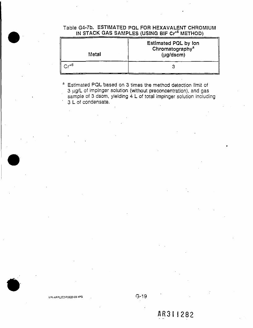
Table G4-7b. ESTIMATED PQL FOR HEXAVALENT CHROMIUMIN STACK GAS SAMPLES (USING BIF Cr+6 METHOD)
Metal
Cr+6
Estimated PQL by IonChromatography3
(ug/dscm)
3
Estimated PQL based on 3 times the method detection limit of3 u,g/L of impinger solution (without preconcentration), and gassample of 3 dscm, yielding 4 L of total impinger solution including3 L of condensate.
URI-APPLIED\R3620-09.APG , G'19
I282

Table G4-8a. SEMIVOLATILE ORGANIC COMPOUND ANALYTESIN STACK SAMPLES (METHOD 0010)Compound(Note a)
Benzo[a]anthraceneBenzo[a]pyreneBenzo[b]fluorantheneBenzo[/(]fluorantheneChryseneDibenzo[a,/7]anthracene1 ,2-Dichlorobenzene1 ,4-DichlorobenzeneFluorantheneHexachlorobsnzenelndeno[1 ,2,3- cdjpyreneNaphthalene(3-Naphthylamine (Note b)2-Nitroaniline4-NitroanilineNitrobenzenePentachlorobenzenePentachlorophenol (Note c)Pyrene1 ,2,4-Trichlorobenzene2,4,5-Trichlorophenol (Note c)2,4,6-Trichlorophenol (Note c)AcenaphtheneAcenaphthyleneAnthraceneBenzo[e]pyreneBenzo[t7f/7r/]peryieneBenzoic acidBis(2-chloroethyoxy)methaneBis(2-ethylhexyl)phthalate (Note d)Butyl benzyl phthalate (Note d)Carbazole4-Chloroaniline4-Chloro-3-methylphenol (Note c)p-Chloronaphthalene
Estimated PQL9(pg/dscm)
0.10.10.10.10.10.20.20.20.20.20.20.2TBD110.20.210.20.2110.10.10.10.10.20.50.50.10.10.10.50.50.5
MRI-APPLIED\R3S20-09.APG G-20
H R 3 I I 283

Table G4-8a (Continued)
Compound(Note a)
2-Chiorophenol (Note c)Dibenzofuran1,3-Dichlorobenzene3,3'-Dichlorobenzidine2,4-DichlorophenolDiethyl phthalate
(Note c)(Note d)
2,4-DimethylphenolDimethyl phthalateDi-n-butyl phthalate2,4-DinitrophenolDi-n-octyl phthalate
(Note d)(Note d)(Note c)(Note d)
FluoreneHexachlorobutadieneHexachlorocyclopentadieneHexachloroethane2-MethyinaphthaIene2-Methylphenol4-Methylphenol2-Nitrophenol4-Nitrophenol
(Note c)(Note c)(Note c)(Note-c)
PhenanthrenePhenol (Note c)1 ,2,4,5-Tetrachlorobenzene2,3,4,6-Tetrachlorophenol (Note c)
Estimated PQL*(ug/dscm)
0.20.20.10.50.20.20.20.20.20.50.20.10.20.50.20.20.20.20.510.10.20.20.2
Notes:a Twenty largest peaks, that may include some of above targets, will
also be tentatively identified and semiquantitated.b Sampling method is not verified for this compound.c Phenolic compounds sometimes present recovery problems.d Phthalates are common sampling and lab contaminates, therefore,
results may indicate compounds are present above the levelactually present.
e PQLs are estimated values based on GC/MS-SIM analysis. ActualPQLs may vary. PQLs were estimated to be 5 times the estimatedMDLs.
MHl.APPLISCy.R3320-OS.APG
AR3II28U

Table G4-8b. PESTICIDE ANALYTES IN STACKSAMPLES (METHOD 0010)
CompoundAldrina-ChlordaneY-Chlordane4,4'-DDD2,4'-DDE4,4'-DDE4,4'-DDTEndosulfan IEndosulfan sulfateEndrinEndrin aldehydeHeptachlorp-Hexachlorocyclohexane
Estimated PQL(Notes a, b)(ug/dscm)
0.20.20.20.20.20.20.20.20.20.20.20.20.2
a PQLs are estimated based on using GC/MS-SIM analysis. ActualPQLs may vary. PQLs were estimated to be 5 times the estimatedMDLs.
b Sampling method is not validated for these compounds.
MRI-APPLIED\R3S20-09.APG G"22
A-R3I I 285
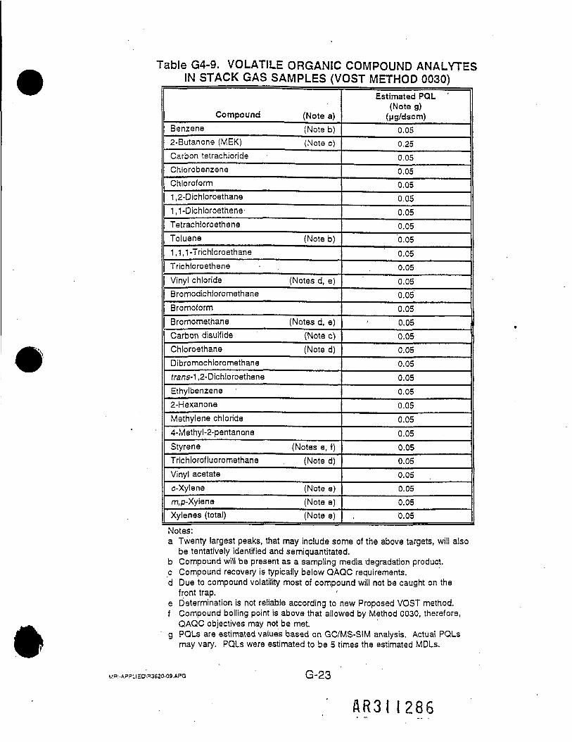
Table G4-9. VOLATILE ORGANIC COMPOUND ANALYTESIN STACK GAS SAMPLES (VOST METHOD 0030)
CompoundBenzene2-Butanone (MEK)
(Note a)(Note b)(Note c)
Carbon tetrachlorideChlorobenzeneChloroform1,2-Dichloroethane1,1-Dichloroethene-TetrachloroetheneToluene (Note b)1,1,1-TrichloroethaneTrichloroetheneVinyl chloride (Notes d, e)BromodichloromethaneBromoformBromomethaneCarbon disulfideChloroethane
(Notes d, e)(Note c)(Note d)
Dibromochloromethanefrans-1 ,2-DichloroetheneEthylbenzene2-HexanoneMethylene chloride4-Methyl-2-pentanoneStyreneTrichlorofluoromethane
(Notes e, f)(Note d)
Vinyl acetateo-Xylenem,p-XyieneXylenes (total)
(Note e)(Note e)(Note e)
Estimated PQL '(Note g)(ug/dscm)
0.050.250.050.050.050.050.050.050.050.050.050.050.050.050.050.050.050.050.050.050.050.050.050.050.050.050.050.050.05
Notes:a Twenty largest peaks, that may include some of the above targets, will also
be tentatively identified and semiquantitated.b Compound will be present as a sampling media degradation product.c Compound recovery is typically below QAQC requirements.d Due to compound volatility most of compound will not be caught on the
front trap.e Determination is not reliable according to new Proposed VOST method.f Compound boiling point is above that allowed by Method 0030, therefore,QAQC objectives may not be met.
g PQLs are estimated values based on GC/MS-SIM analysis. Actual PQLsmay vary. PQLs were estimated to be 5 times the estimated MDLs.
MRI-APPL!ED\R3S20-09.APG G"23
AR3II286

Table G4-10. POLYCHLORINATED BIPHENYL (PCS)ANALYTES IN STACK GAS SAMPLES
PCB HomologGroup
Mono
Di
Tri
TetraPenta
Hexa
HeptaOcta
Nona
Deca
Estimated PQL*(ng/dscm)
0.5
0.5
0.5
0.5
2.5
2.5
5.0
5.0
5.0
10.0 ,
* PQLs are estimated values. Actual PQLs may vary.PQLs were estimated to be 3 times the MDLs.
MRI-APPLI=0\R3620-09.APG G"24
AR3M287

Table G4-11. COMPOUNDS IN RISK ASSESSMENT BUT NOT IN RISK BURNCompound
AcetoneAcrylonitrile
BenzaldehydeBenzo[y]fluorantheneBenzoyl chlorideBenzyl chlorideBiphenyl2-Chloroethyl vinyl etherChloromethane
Dioctadecyl ester phosphoric acid
Fenac (2,3,6-Trichlorophenylaceticacid)2-Fluoro-4-nitrophenolHexadecanoic acidMono(2-ethylhexyl) esterhexadecanoic acidOctadecanoic acid1,2,3,4,43,9, 10,1 Oa-Octahydro-1, 4a-dimethyl-7, 1 -phenanthrenecarboxylic acid
QuinolineUndecaneCyanide (as acetonitrile)BromochloromethaneA/-NitrosodiphenylamineTotal volatiles
CommentsWater solubility results in unacceptable recoveries.Water solubility and reactivity results in unacceptablerecoveries.
Significant degradation product of XAD.Co-elutes with other benzofluoranthenes.Compound is not a standard 8270 analyte.Compound is not a standard 8270 analyte.Compound is not a standard 8270 analyte.Compound is not a standard 8270 analyte.Compound too volatile to be analyzed reliably byVOST.Compound is not a standard 8270 analyte.No validated sampling method.
Compound is not a standard 8270 analyte.Compound is not a standard 8270 analyte.Compound is not a standard 8270 analyte.
Compound is not a standard 8270 analyte.Compound is not a standard 8270 analyte.
#
Compound is not a standard 8270 analyte.Compound is not a standard 8270 analyte.No validated EPA method.Method specified internal standard.Compound degrades during analysis.No known available method.
MRI-APPLIED\R3520-09.APG G"25
A83II288

G.5RISK BURN
SAMPLING PROCEDURES
G.5.1 STACK EMISSIONS SAMPLING
The stack gas sampling will be performed using the following procedures:
1. Method 0050 sampling train for particulate/HCI.
2. Method 0010 using a Modified Method 5 sampling train for semivolatileorganic compounds and pesticides (MM5-SV).
3. Modified Method 5 sampling train for sampling PCDD/PCDF per EPAMethod 23 (MM5-D/F).
•
4. Modified Method 5 sampling train for sampling PCBs, based on EPAMethod 23 with modifications appropriate for PCBs (MM5-PCB).
5. Draft Method 29 using a Modified Method 5 sampling train for multiplemetals (MM5-MM).
6. EPA BIF method using a Modified Method 5 sampling train for hexavalentchromium (MM5-CR).
7. Method 0030 (VOST) train for volatile organic compounds (two trains).
8. Continuous emission monitor for S02.
G.5.1.1 Particulate/HCI Sampling Train
The sampling for particulate/HCI will be the same as presented inSection 5.1.2 of the Trial Burn Plan.
Mpi.A=ou=D\R3620-09.APG G'26
AR3II289

G.5.1.2 MM5-SV Sampling Train for Semivolatile Organic CompoundsIncluding Pesticides
The sampling method and sampling train configuration will be the same aspresented in Section 5.1.1 of the Trial Burn Plan.
G.5.1.3 MM5-D/F Sampling Train for PCDD/PCDF
The sampling train configuration will be the same as presented inSection 5.1.1. of the Trial Burn Plan. Operation and recovery of the MM5-D/Ftrain will be very similar to that presented in Section 5.1.1 but will be modified inaccordance with EPA Method 23 for PCDD/PCDF.
G.5.1.4 MM5-PCB Sampling Train for PCBs
The sampling train configuration will be the same as presented inSection 5.1.1 of the Trial Burn Plan, but the XAD resin will be prespiked withselected PCB field surrogates. Operation and recovery of the MM5-PCB train 'will be very similar to that presented in Section 5.1.1 but will be modified inaccordance with EPA Method 23.
G.5.1.5 MM5-MM Sampling Train for Metals
The method will be the same as presented in Section 5.1.2 of the TrialBurn Plan with the following changes due to changing the target metals list.Figure G5-1 is a schematic of the sampling train to be used to measure metalsemissions. This sampling train includes two additional impingers containingKMn04/H2S04 solution to determine the Hg emissions from the stack.,
G.5.1.6 MM5-CR Sampling Train for Hexavalent Chromium
The stack gas will be sampled for measurement of hexavalent chromium(Cr+6) emissions using EPA's method titled "Determination of HexavalentChromium Emissions from Stationary Sources (Method Cr+6)," as specified in 40CFR26Q, Appendix IX, Section 3.3. A schematic of the sampling train employedin this method is shown in Figure G5-2.
MHI-APPLIED\fl3620-09.APG G'27
AR3II290

ST
G-28
A R 3 I I 2 9 I
c'5
•— — — o» *s? vP "••
g 11 -E- _~ x - - co;* °M. o cT 9 w11 Hi.<£ I 5? S? ° T-o r> " 'T ~ .-a-i O >. ^ _j -• c-E Z - = i =, 31 i-,.8 5 £ § 8 1 | b , . - . - -
C/3 o? O K O5 W S « ^^^ c n S H ^ r a c i o i w 1" c5| l i " i | l l l ES s = £ d - S c c ( 1 )o a j c o s - o i a i c o r *o a <» c a a 5 a o' § l 5 | s " S s i ^l l l l l l l l ^S S 0 2 5 S 5 2 J ,
O0>DcniZ

coCO
0)>.2Q.V)•
Q.J=»*•*
ic"co
0)O)c
•'5.
O)
Uk_uCD
o***•oo*•*»*COE0)uCO
inO0)L.3cnIT
IE
G-29
AR3II292

The Cr+6 emissions will be collected isokinetically from the stack. Toeliminate the possibility of Cr+6 reduction between the nozzle and impinger, theemission samples will be collected with a recirculatory train where the impingerreagent is continuously recirculated to the nozzle. Recovery procedures includea postsampling purge and filtration.
The sample gas flow rate metering system is identical to that specified by• EPA Method 5. Sampling procedures will be as specified in the EPA BIF Cr+sMethod; however, a higher concentration (e.g., 0.3 N KOH) may be used insteadof 0.1 N KOH to ensure that the solutions remain alkaline when sampling theincinerator stack gas that contains acid gases. Immediately after sampling, thetrain is purged with N2 for 30 min, after which the probe, impingers, andconnecting lines are rinsed with deionized water. This rinse and the impingercontents are combined and filtered. The filtrate is returned to the laboratory forCr+6 analysis by ion chromatography (see Figure G5-3).
Holding time between sampling and analysis will be 14 days. No holdingtime limits are specified in the method; however, telephone discussions with thedevelopers of this train indicated that 14 days is very reasonable based on theirstability experiments.
G.5.1.7 VOST for Volatiies
The stack gas will be sampled for measurement of the volatile organiccompounds listed in Table G4-9 using EPA's method titled "Protocol for theCollection and Analysis of Volatile POHCs Using VOST," as specified inSW846-0030. A schematic of the VOST employed by MRI to perform thismethod is shown in Figure G5-4.
Two identical VOST trains will be used for sampling in each run (VOST-Aand VOST-B). Train A will be used to sample stack gas with four pair of VOSTtraps in each run (20 min per pair) plus one field blank pair and one trip blankpair per run. These traps will be analyzed for the compounds listed inTable G4-9, using full scan GC/MS. Train B will be used to sample stack gaswith three pair of VOST traps in each run (20 min per pair). However, the firstpair in Train A will be inserted, leak checked, and started before preparing the
MRi.Ac=_'E3'.R3620-09.APG G"30
AR3II293

w.c'c cuo inO .£* CC
Q.
coCO CC COrr cu
O 'ocoCC
cSEoO
2:
iZ
S! C
2*->O)
Q.
03COCo'to
Q.0) 2Sec g5
CU v. oN O
15 O< o
_
0)
O'o
ICOcH—
€O"co0>J=oC/3
criLOOL.3O)iZ
<
G-31
AR3II29U

' >.©V J
ll<5 H
in-4 i
G-32
AR3II295
<f)o>c'2*•*
cn1CcL
,1COu'E ;COcn
o
inO033cnIT

first pair in Train B. Likewise for other succeeding pairs. The three pairs fromTrain B will be analyzed by GC/MS-SIM for quantitation of those compounds inTable G4-9 that were not detected in the VOST traps from Train A but where thePDLs for the full scan analysis was not as low as the PQLs shown inTable G4-9.
The VOST method calls for collecting a 20-L sample of effluent'gascontaining volatile PICs withdrawn from a gaseous effluent source at a flow rateof 0.5 to 1.0 L/min. In this train, the gas stream is cooled to 20°C by passagethrough a water-cooled condenser, and the volatile PICs are collected in a pair ofsorbent resin traps (cartridges). Liquid condensate is collected in a dropoutbottle placed between the two resin traps.
VOST preparation, sampling procedures, and sample recovery will bespecified in Method SW846-0030, with the clarifications and modificationsoutlined in the following paragraphs.
t
The sorbent cartridges for the VOST are of the inside-inside (I/I)configuration in which only a single glass tube is used for each of the two tubes.The second sorbent cartridge is placed in the sample train so that the samplegas stream passes through the Tenax layer first and then through the charcoallayer. The resin is held in place by Teflon-coated stainless steel screens andclips at each end of the resin layer. Threaded end caps are placed on thesorbent cartridges after packing with sorbent to protect the sorbent fromcontamination during storage and transport. The tubes are prepared by MRI'slaboratory.
During the thermal conditioning, the cartridges are installed in a speciallydesigned manifold which permits the nitrogen purge from the traps to be individ-ually monitored by a flame ionization detector (FID). The conditioning iscontinued until the FID response indicates the traps are clean (less than 5 ppbtotal hydrocarbon as propane). If after 24 hr of purging the trap is stillcontaminated, it is discarded. All trap preparation will be done at MRI.
After the traps are conditioned, they are capped (sealed) and placed into aprecleaned steel can which is also sealed for shipment. Each can contains a
MRI-APPLIED\R3620-09.APG G"33
AR3II296

small amount of charcoal for shipment. The cans are stored on ice until thetraps are analyzed.
A continuous heated Teflon line is used as the probe and transfer line tothe VOST console. This configuration eliminates the possibility of in-leakage atthe joint between the borosilicate or quartz-lined stainless steel probe and theTeflon sample transfer line described in the method.
A pair of field blanks for each run is obtained by removing the end capsand exposing a pair of traps to ambient air for the same period of time as oneset of sampling traps is exposed when inserting and removing them from theVOST apparatus. These field blank pairs are analyzed along with all othersample traps. . • _
A pair of trip blanks (unopened) will be transported with each shipmentbatch of test samples and will be analyzed only if field blanks (ambient-exposed)show significant contamination (> 76 ng of any one analyte). A pair of laboratoryblanks for each lot of traps prepared will be stored at MRI and will'be analyzedonly if the trip blanks show significant contamination.
i • - i
The VOST traps removed from the sample train are immediately capped.A label is placed on the end cap of each trap to indicate the sample run number.for ease in identification. The VOST trap samples will be placed in cold storage(< 4°C) upon receipt in the laboratory. The VOST samples have arecommended 14-day holding time from collection to analysis.
A VOST audit cylinder, if available, will also be sampled, using three trappairs.
G.5.1.8 Continuous Emission Monitors
Stack gas will be continuously monitored for S02 during each run of theTrial Burn, in accordance with EPA Method 6C.
The stack gas will also be continuously monitored by OHM for CO, NOX,and THC using OHM's PY*ROX 8212 GEM system. All data except THC will be ^i^
MRI-APPLIED\R3620-09.APG G"34
AR3M297

corrected to 7% 02 equivalent per procedures described in Appendix B of thisTrial Burn Plan.
G.5.1.9 Oxygen and Carbon Dioxide Sampling
The sampling method will be the same as presented in Section 5.1.4 ofthe Trial Burn Plan.
G.5.2 Waste Feed Sampling
The waste feed will be sampled and analyzed by OHM in accordance withthe normal daily procedures included in the Chemical Quality Management andSampling Plan (CQMSP). A summary of that sampling and analysis is shown inTables G4-1c and G4-1d. ,
G.5.3 BOTTOM ASH SAMPLING*
Bottom ash sampling will consist of sampling a combined stream fromthe kiln, cyclone, and SCC. The sampling will be performed by taking a - 50-ggrab sample every 30 min and combining the grab samples into a singlecomposite sample. The composite will be spilt into five samples for the followinganalysis:
Volatiles - See Table G4-2Semivolatiles, including - See Table G4-3
P-NaphthylamineHerbicides - See Table G4-4TCLP Metals - . See Table G4-5Dioxins and Furans - See Table G4-6
G.5.4 FLY ASH SAMPLING
Fly ash sampling will consist of sampling a combined stream from theevaporative cooler and baghouse. The sampling will be performed by taking a- 100-g grab sample every 30 min and combining the grab samples into a single
V=I-APPLIED\R3620-09.APG G'35
AR3M298

composite sample. The composite will be spilt into five samples for the followinganalysis:
Volatiles - See Table G4-2. Semivolatiles, including - See Table G4.3
P-Naphthylamine•Herbicides - See Table G4-4TCLP Metals - See Table G4-5Dioxins and Furans - See Table G4-6
G.5.5 SCRUBBER WATER SAMPLING
Scrubber water sampling will consist of taking a - 50-mL grab samplefrom the scrubber water recircuiation loop every 30 min and combining the grabsamples into a single composite sample. The composite will then be analyzedfor TCLP metals listed in Table G4-5.
o
OG"36
AR3I1299

G.6.1.2 Analysis of MM5-SV Samples
The MM5-SV samples will be analyzed for the semivolatile organiccompounds listed in Table G4-8a (which includes p-naphthylamine) and forpesticides (Table G4-8b) using the methods and procedures described inSections 6.1.1 and 6.2.1.1 of the Trial Burn Plan. In addition, as part of theGC/MS analysis for semivolatile organics, the 20 largest peaks will bedetermined. Those peaks which are not compounds in Table G4-8a will betentatively identified and semiquantitated. In this regard, it must be noted thattentative identification means, in some cases, that a specific compound cannotbe identified. For example, the peak might be identified only as "C9 alkane."
G.6.1.3 Analysis of MM5-D/F Samples
The MM5-D/F samples will be analyzed for the congeners listed inTable G4-6 using EPA Method 23 procedures as described in Sections 6.1.1 and6.2.2 of the Trial Burn Plan, including minor exceptions given in Table 6-1, TotalPCDD/PCDF will also be determined. '
G.6.1.4 Analysis of MM5-PCB Samples
the MM5-PCB samples, collected in accordance with EPA Method 23.sampling procedures, will be prepared and cleaned up using EPA Method 23procedures, modified as appropriate for PCB analysis instead of PCDD/PCDFanalysis (e.g., deletion of alumina cleanup step that removes PCBs). Sampleswill be analyzed by EPA draft Method 1668, modified (expanded) to includequantitation of all PCB homolog groups, as listed in Table G4-10. ThisHRGC/HRMS method provides low detection limits as shown in Table G4-10.
G.6.1.5 MM5-MM Train Analysis for Metals
MM5-MM samples will be analyzed for the metals listed in Table .G4-7a. •This analysis will be done using the procedures, and modifications, described inSections 6.1.2 and 6.2.6 of the Trial Burn Plan but will include analysis of thepermanganate impingers for Hg (see Section G5.1.2).
MRI-APPLIED\R3620-09.APG
AR3II300

G.6.1.6 Hexavalent Chromium Analysis
The impinger contents of each hexavalent chromium sampling train will becombined into one sample for each run and filtered to remove any precipitateswhich may have formed in the alkaline impingers. After filtering, an aliquot ofeach sample will be submitted to the laboratory and analyzed for Cr*6 by an ionchromatograph equipped with a postcolumn reactor and a visible wavelengthdetector. The IC/PCR separates the Cr+6 as chromate (CrO+6~) from othercomponents in the sample matrices that may interfere with the Cr+6-specificdiphenylcarbazide reaction that occurs in the postcolumn reactor. Field blankreagents will be analyzed in the same manner as the train samples. Analysisprocedures described in "Determination of Hexavalent Chromium Emissions fromStationary Sources" (dated December 1990) will be followed, except for a fewminor modifications as listed in Table G6-1, and other changes associated with,the use of a higher concentration (e.g., 0.3 N) KOH in the impingers, ifapplicable, which would be done to ensure that they remain alkaline.
MR|.APPLI£D\R3S20-09.APG G-39
A R 3 I I 30 I

Table G6-1. MODIFICATIONS TO THE EPA HEXAVALENTCHROMIUM METHOD
Note: The following modifications for the Cr+s method described in the "EPAMethods Manual for Compliance with the BIF Regulations," December 1990,are listed by applicable paragraph. Paragraphs which are not listed are not "changed.
Paragraph 3.2.3.4.4 0.45-u.m filter cartridge. For the removal of insolublematerial. To be used after train recovery and prior to sampleinjection/analysis.
Paragraph 3.2.4.4.3 Cr(VI) Calibration Standard. (Modification of one sentenceand addition of one sentence.) To prepare working standards, dilute the stocksolution to the chosen standard concentrations for the instrument calibrationwith 0.1. N KOH to achieve a matrix similar to the actual field samples. Thissample should be prepared fresh every 24 hr.
»
Paragraph 3.2.4.4.4 Performance Audit Sample. (Addition.) In the event thatthe performance audit sample is unavailable, a check standard wfft beprepared from an alternate lot of potassium dichromate which will function inthe capacity of the performance audit sample.
Paragraph 3.2.6.2 Calibration Curve for the IC/PCR. (Modification of onesentence only.) The individual responses for each calibration standarddetermined before and after the field sample analysis must be within 5% of theaverage response or, for a point before and one point after sample analysis, a10% range, for the. analysis to be valid.
MRI-APPLIED\R3S20-09.APQ G-40
AR3II302
In addition to the analytes listed in Table G4-9, the GC/MS analysis willinclude determination of the 20 largest peaks. Peaks for compounds that are notamong the analytes listed in Table G4-9 will be tentatively identified andsemiquantitated. This tentative identification may not always allow identificationof specific compounds.
G.6.2 ANALYSIS OF ASH SAMPLES
Bottom ash and fly ash samples will be analyzed for several types ofanalytes, as shown previously in Table G4-1b, which include the following:
• Volatile organics• Semivolatile organics (including p-naphthylamine)• TCLP metals• Herbicides.• .Dioxins and furans
Ash samples will be analyzed for the volatile organics listed in Table G4i2,semivolatile organics listed in Table G4-3, and TCLP metals listed in Table G4-5,using the same procedures described in the relevant portion of Sections 6.1.5,6.2.1.2, and 6.2.6 of the Trial Burn Plan.
Analysis of ash samples for the herbicides (Table G4-4) will be doneaccording to Method 8151 in SW-846. This method basically involves extractionwith methylene chloride, derivatization with diazomethane to form the methylesters, with analysis using GC/ECD.
Ash samples will also be analyzed for dioxins and furans in accordancewith EPA Method 8290 in SW-846 using HRGC/HRMS.
G.6.3 ANALYSIS OF SCRUBBER WATER SAMPLES
The scrubber water samples will be analyzed for TCLP metals listed inTable G4-5,per the TCLP extraction procedure in EPA Method 1311 (asdescribed in Section 6.1.5 of the Trial Burn Plan for ash samples), with digestionand analysis of extracts as described in that same section, and relevant portionsof Section 6.2.6.
MRI-APPLIED\R3620-09.APG G"42
AR3M303

I— m4fmUJSa.SaLUo•za.s<U)
COCIQ<;u-jaX5LLI£OLUiZ5oSa
k £1 *W LU
iaz
ALIBRATION PROCEDURES /
O
ri0»
• 1
L
>.ocaca£
5±
8Sa.CI)u2
•5•8c2•«CDI£'BCC
Calibration technique
w0)CD
S.
1.a'cEao•cQ.
5., o11of th
ree measuremi
>nce between
high E
mm
c 2 _CO CD •CD S O2 '-5 vi
Micrometel
Measure diameter to
nearest
0.001
in
S.XocSg0.
*-
• to minibum
•gQ.
d calibration factor
ooCDQC
Eja"ra•ck_ofb.2732
if pretest ca
librat
ion
uS5B
1 'SO"tou•J3•cu
Calibrated
• c\TfCo eCO .OCt &LL CDO COo in"S-o8 sSB CD'§2"c5 1 S:0 <
Gas meter volume
CJ
"=3wS'a73S
• to m
inibum
•I 1Q. ji
LLo
S
WCD"3
O
J1<
Compare to mercury-in-glass
thermometer
1
Gas meter tempera
«'
IS
1COTJi
to minibum
•IIQ- 5
3
of minimum
absolu
temperature
in "o»• IS-H "to
3CDI•.s _c ES "U"o •«CL >•CD "3 S°-3O Oa g175 §cn CDZ £
Heated
block monitored with
potentiometer thermocouple
system
58cCDCA
Stack temperature :
tr
to
Sto•octo
to minibum
•i e£J
LLo$1
i_2CDE
1I
Compare to mercury-in-glass
thermometer
£3toCD
Final impinger temp
sensor
in
10)'to13S
to minibum
•£ e<E5
LLoin•H
1 'o
CD£
2
1
Compare to me
rcury-in-glass
thermometer
hit
«
§
Filter
temperature s
co"
1.2'OT•octo
to minibum
•3 e£ J
EEinsi
V.j>CD
IC
3
S£•iCD
Compare to me
rcury barometer
Aneroid barometer
|S
1W2'to
1
to minibum
1 E£J
to
1OCM
CCBCDCD
£CD
2CDQ.1O
EPA Method 2 dimensional
measurements
S-type
pitot
tube
03
to minibum
wO•cCL
1 calibration factor
Boy1
1XI•toSto<
Ito
pretest c
alibra
tion
1
0?«
^CD
Wet Test MI
Wet Test Meter
40 CFR 60, App. A, Method 6,
Section 5.1
CD
1w2
V)
i
0>
CFR 60, Appendix A
a
oCL
S
<i
G-44
AR3I

QI-
g<
%«|£|oCC LUO «JLL LUco to>5F|o AUJ33°12<t V)U H1^2S;
o"in'o£ct
JiT2o•»
10)a-cuLL
C_o73
1cu"5TJ"oTJ|cu
.S"ffl
5203"532CL
H
Z
z
CO2IS11CD ~•a ESig §6g
j«:caJ2
Extraction
fluid
aQ.CC0s-sv?.
0COo r5 8
QCO>
CO
coCD
o2CO •CL
£
Matrix spike of
(MS/MSD)
ECO
j£co**•• 2-g iE -a0 o §CD cn
</)
"33a.o
z-T—
S**5
8
_CD
c"sCOUJ
V)(Jj
f o5 CO
||
Q. mco a
z
z
cuo6
Method
blank
QCLCCS?LT3CO
1
cu
6
.WJ
cocu1aQ
Qa.CCc -inCO
obCO
o 1"*— ^
>5 oO OCO w
X
1CDCL
o
COV)CO
O
cofflo1-TJ.C
£ cu"
Matrix spike wi
p-naphthylamin
J=mCO
IS
1ca«caE
I"aTcE
Ol CO"•-SI1° Hi iCO ••§, c
z
vP0s-oCO
o—vP0s-O
_coQ.
coCO
uCOUJ .
COa. •CO"5O)
§to in
J 1•'oLCO 2
Z
Z
cu
CD
Method
blank
fCOCO
3=TJCO
1 :E.ooCQ
cnCUTJ
1COX
o
IO
S
G-45
AR.3I 1305

TJ0)
o
icoco
Precision
Accuracy
c?CDcr£LL
C.013•fCDo3TJ"oT5
"33
x•£13>
20)"53COcoQ.1/3CD1—
Z
5s?OCM
_CD
cotoocoLU
"CO CL
ith isotopic
standards
8290
3 TJ "0CD J2 0.* 13 •£•5.-Q aco .2 2
£L_ CD
Si Q Is-. 05CNJQ. CO. §Vi C CM 0
Z
.x
1.c5CD
*<™>0)O
6
CO'cn~caCOCD
1. Q.Q
Z
To demonstrate
I.S. responses
and non-
contamination
.X
1r*CJcoCD
J5CDo6
ei-Q
'CD
.cinCO
TJCco.cCOCOE0Qm
in2i?tc"xo .b
Z
1o
i
CD
I"coCO1LU
cu13050O CDfc CM3 CO
£i O•*2 f~*f
CL CDCO Q.
Z
,CD
O
2TJO
"33
Q0.CC0s-LOco
Z
CD
1
_(fl
fcacu1O.Q
COCO
ir*CO.CU]COEocom
COO0
G-46

12at-
OR MEA
SURE
MEN
EMISSIONS)
u. —CO 2LU Z> <P 00 OC
-2B. SPECIFIC OBJE
(STACK GAS 0
a_«
I
cision
22QL
1
I
Frequency
_o13
Method
of determi
•cle2
c/aaESc'uCD1-
Z
Z
TJ
Once
for
verif
icatio
lof system control a
• non-contamination
c'2
COCO
Z
0
1O CDisS £....."£CD-aocnT5
QXCD
6
CDCL
COto . — .11O j£
IT s2-g11
^QCO tocc .—p TJ CD0s CD >LO S ov §.£
bLO
2 c5
O Q)LO w
Every sample and
blank
^3
^ CD "3r-S*-C O
Spike Method 8270
surrogates
(isotopical
labeled compounds c
similar to
target SVOi
c o"1 1> CO TJCO CD o
1 CL *~LO f— *254;2 cn -
¥.£ cn" C CDCM J2 •§
c £ In
O — co> ^ cc "2CO sb. co
^
z
O C0) i: o
lit!|t"slQ cn co u
c
CDO.
tCD
6to
S £•
«1| |
iillI tli
QCOCC0sLO(N+1
5?LOCMT-
'5Q.CL2
UJ
CL2
iSpike two surrogate
compounds onto Ten
nQCO rCCv90s-0LO
a? 2S o = 5 .S |o I'S'S'SW •5 IfHI •S i i §•.£"£
•5ct2 •H!|> =. 1
i I1to j0.2«—
fc0> II
"oCM
cnOO>
CO
o
§CDO
1WO
8 «1 »
«* 8-CD CD
CU
0> £
1?••?= to
s.1CD cco g2J .5"(1) C-c §I- to
G-47
AH3II307

•a CD -o g -H «z -s c -s •? ;; « 1o
oo,m
oz.CO
c.0'c/5'u2iO.
>,o21<
| .
Frequency
Ihod of determination
CD
.'gjio
o3"53E25O."c/SCD
Z
Z
E "o
One per tes
tcondition;
demonstrate syste
control and ver
ifynoncontamination
.test samples
c1
JCO
"Soo
Q CuCO = wrf CD CDa i "3.5? 5 EO CD COT .Q to
v£
80 §T; §O QJr** w
•iCOCDI-cflcn2.2"o cCO COLU xi
•§ w CQso iTJ .<;
;urrogates (spike
preparation of X
ng tr
ains)
— % i"
QCO C cn
0s? ^ "§•
§1 S55s
§5 w CM ,_
OS? <D 5s* ~ O«•* ^ j~ Q d3 t
^ u) Tii o flj ^•t v- - — L. J=
•oCOCD1cotoTJ.CD
_ TJ CQCO _^ CCi's- 5•i||
fc 15 E .2•|* si-Cl CO O —5 §-.= cS
Z
CC0
12ioL.
——
'SLtoCD
O '
1 sample (blank
ts spiked with
ndent standard of
PCDD/PCDFs)
fill3131
z
J3TJ
'uCDCL(0 <co Q.< LU
CO1CO<nT?COCD
O
ndent QC
check
rd (EPA PCDD/PCDF
f available)
co cc —•§-•§•§£. "to ca
to-CD I-CMco "OtO Oc —
trj <5 CLly.COLLQOQ.QQOO.
CDCC
cmcnCC
03
co
cr5
G-48
4R3I1308

TJO
O
CQ
rC3_oCO
c.0'co'uCUIX
^
Occw
§<
Frequency
c.0'S
Method
of determin;
x152
cnOJ"53E2coCL-cnCD
Z
Z
p **
One per test
condition; to
demonstrate systei
control and ver
ifynoncontamination (
test samples
c1
coca .
QQ.OC0
o
M
g
o s^T— ^
i Oo coLO !_
CDCLCOcoTJ
«*•• 2
O TJCO GLU co
TJ
^"oCL —-^ n
III15 co CLc? S-Eg i^ ro- Q, (/)in osoCO *C ;?° -o '=
(U ~ rfLL .£ X
QO.CC^
g**
?9CO""
So SIs- cu• su.<— co
CM CL
CO_CD
<atn•aCD
co _3JLU J3
^.1
t5•s §
Spike PC
B labo
ratory
surro
gXAD
sample
prior
to ex
tract!
ClQ_ ^__
S? 0in C—
>• &
£.cu8h_
o ~10 QT™ ti
0 f^
§
Four XA
D blan
ks, to
determine i
nitial
precis
iand a
ccuracy (
IPR)
Spike f
our bl
ank XA
D with
surrog
ates a
nd na
tive P
CBs
(IPR)
^srSQw~*3 -— *
T CO
S
One spi
ked bl
ank XA
Dwit
h each b
atch of
samples (to
determine
ongoing pre
cision
and
recove
ry (OPR)
<n03OQ.
I•B'sQ
CCQ2 ___
TJ.C _§'2 "33cn0 <
Ig !_• CD J2 CM
cnCO0Q.
sLUJo>
1Jo
s1J=
5t-
congeners but
are l
owi
CDoo.o>
"5•35
as•ao'§:caiCC
ip
,j>.£.o
1•sCL
"]2ns
8iso
G-49
. AR3II309

Y*
i—Un*
1BJECTIVES FOR MEASUREMEN
AS METALS EMISSIONS)
\~j 05
LL O
11CO
CJ
a_«i—
Q
"35'ufja.
f
1
o
LU
Method
of de
termin
ation
.X
1os
£2&•ft '&
.co E1 — coi.
^
^
One to de
monstrate s
ystem
contro
l (no gr
oss co
ntamin
ation)
and to
determine b
lank
correc
tion v
alues
2
J
i i.|f|
III
z
59O
3159 gS(J
CO
CQDC
After each
initia
l cali
brati
cn
u= ^
.2 -o 1
t! "2 J-g .<g <qO ^f
oil
^
•s §S-. »"c "S
III** £2 CQ59 S «15 SS-<JJ
E ^ rf— 2Pri
or and
subsequent
toanalyses or
every
8 hr.
whichever i
s more
freque
a.o
Interf
erence
check s
amples
(I1
only)
oCLQC59OTr
Lo
3
59tS
CQCC
-5 s
Two co
ntrol
spikes
for e
ecomponent (or
combined
components) at 10
X the
estima
ted de
tectio
n limi
t I_-S
Spiked
lab r
eagent
blanks
simula
ting f
ront-h
alf an
d back
-tra
in components
-
i S
aa.CC52LT5»•
3*— >HO ~ZS<w Cu
5? Sin — ;cj .2j j C
s -c£ S
i—CDS
Two NI
ST tr
aceabl
e std
refer
emat
erial (SRM) on
filter
media
? 2-EH2 c £I fi
(' *
"c5"cu2
^
z
z
After
initial
calib
ration
todemonstrate s
ystem c
ontrol
and
noncontamination
Analys
is of
blank
reage
nt
•o.CO _ ."5 CDCD </5•CD 'o•o cO r^•«• .Q AQ_CC 259 >Ln
i
CD
I"
1LU
Duplic
ate an
alysis
of fi
eldsamples
CC
Q0.DCgLn
590
2 TOo^ oc CJCJ> CO,
After
initial
calib
ration
'Dup
licate
analy
sis of
QAperformance s
ample
oin f.
12
<o
<5
CCCC
Ica
cc•E
|CJ.CCU
11s,o"co.c
s•sO
I ,1 I
ctca fi I
G-50
AR3M3IO

G.8RISK BURN
REPORTING OF RESULTS
G.8.1 REPORT FORMAT
Test results will be reported within 30 to 45 days after completion ofsampling. The following is an outline of the Risk Burn Report.
1.0 Introduction
2.0 Incinerator Operating Conditions
3.0 Test Results*
3.1 Stack Results
3.1.1 Particulate/HCI/CI23.1.2 Semivolatiles and Pesticides3.1.3 PCDD/PCDF3.1.4 PCBs3.1.5 Volatiles3.1.6 Metals and Cr+6
3.2 Bottom Ash Results
3.2.1 Semivolatiles3.2.2 Volatiles3.2.3 Herbicides3.2.4 TCLP Metals3.2.5 Dioxins and Furans
3.3 Fly Ash Results
3.3.1 Semivolatiles3.3.2 Volatiles3.3.3 Herbicides3.3.4 TCLP Metals3.3.5 Dioxins and Furans
* Note: Waste feed analysis results will be reported separately by OHM perthe CQMSP procedures.
MRI-APFUED'.83620-09.APG ' . G"51
A B 3 I I 3 I I

3.4 Scrubber Water TCLP Metals Results
4.0 • Quality Assurance Report
Appendices
Appendix A—Field Sampling Data and Sample TraceabilityAppendix B—Process and Feed Rate DataAppendix C—Modified Method 5 CalculationsAppendix D—Particulate/HCL/CI2 ResultsAppendix E—Metals Analysis ResultsAppendix F—Hexavalent Chromium Analysis ResultsAppendix G—Semivolatile Organic Analysis ResultsAppendix H—Herbicide Analysis ResultsAppendix I—PCDD/PCDF Analysis ResultsAppendix J—PCB Analysis ResultsAppendix K—Volatile Organic Analysis ResultsAppendix L—Sampling Equipment Calibration Data
G.8.2 INCINERATOR OPERATING CONDITIONS
Incinerator operating conditions will be reported as follows:
Incinerator Operating Conditions
ConditionSolid Waste Feed Rate (Ib/hr)Kiln Temperature (°F)
SCC Temperature (°F)pH of Scrubber Water
Stack Velocity (fps)
Run 1 Mean Run 2 MeanAverage ofthe Means
In addition, any waste feed shutoffs and the cause of those shutoffs will bereported.
MRI-APPLIED\R3620-09.AP3 G'52
A R 3 I I 3 I 2

G.8.3 TEST RESULTS
G.8.3.1 Stack Results
Stack results will consist of emission concentrations for each of thecompounds listed in Tables G4-6, G4-7, G4-8, G4-9 and G4-10, and will includethe semiquantitated concentrations of the 20 largest peaks from the analysis ofvolatile and semivolatile organics. Dioxin emission concentrations and emissionrates will be provided as 2,3,7,8-TCDD equivalents. The Toxicity EquivalencyFactors presented in Table G4-6 will be used to convert the various dioxins andfurans to 2,3,7,8-TCDD equivalents.
Stack test results, as well as all results for other effluents, will include thefollowing:
• Documentation that sampling met isokinetic requirements (90-110%)-• Percent recovery for all surrogates,• Results for any blanks or spikes or other QA/QC method requiremenis,• A quality assurance narrative describing any deviations from the
method and any QA/QC concerns or issues noted regarding thesampling or analysis procedures,
• Other data or information which is normally considered a part of themethod.
Data in the report may include use of certain qualifiers as defined by thefollowing symbols:
U - Indicates compound was analyzed for but not detected,• J - Indicates an estimated value,
N - Indicates presumptive evidence of a compound,B - Indicates compound was found in the associated blank as well as in
the sample,E • This flag identifies compounds whose concentration exceeds the
calibration range of the GC/MS instrument for that specific analysis.D - This flag identifies all compounds identified in an analysis at a
• secondary dilution factor.
MRI.APPLIEaR3620-09.APG G-53
*R3-I I 3 I 3

A - This flag indicates that a Tentatively Identified Compound (TIC) is asuspected aldol-condensation product.
X - Other specific flags may be required to properly define the results.
G.8.3.2 Bottom Ash Results
Bottom ash results will consist of concentrations of each of thecompounds listed in Tables G4-2, G4-3, G4-4, G4-5, and G4-6. Dioxinconcentrations will be provided as 2,3,7,8-TCDD equivalents. The ToxicityEquivalency Factors presented in Table G4-6 will be used to convert the variousdioxins and furans to 2,3,7,8-TCDD equivalents.
G.8.3.3 Fly Ash Results
Fly ash results will consist of concentrations of each of the compoundslisted in Tables G4-2, G4-3, G4-4, G4-5, and G4-6. Dioxin concentrations will beprovided as 2,3,7,8-TCDD equivalents. The Toxicity Equivalency Factorspresented in Table G4-6 will be used to convert the various dioxins and furans Jo2,3,7,8-TCDD equivalents.
G.8,3.4 Scrubber Water Metals Results
Scrubber water results will consist of TCLP concentrations of the metalslisted in Table G4-5.
G.8.4 QUALITY ASSURANCE REPORT
The QA Coordinator will prepare a QA report summarizing the results ofall audits conducted and assessing the quality of the data relative to theobjectives set forth in Section G.7. However, the target analytes in the varioussample matrices are extensive. Their analysis in these matrices is more in thenature of research rather than being standard analytes employing well knownand well characterized analysis techniques. The sampling and analysistechniques to be used are considered to be the best available, but have not beencharacterized (i.e., validated) for these matrices, especially the stack emissions.
MRI-APPLIED\R3S20-09.APQ G"54
A R 3 I I 3 I

It is therefore expected that some of the QA/QC objectives may not bemet. In such cases, the results will be flagged in the test report and the QAreport. • It is understood, based on discussions between OHM and EPA, thatflagged data would be acceptable if there are QA/QC problems (i.e., the RiskBurn tests would not be considered as invalid). Any such problems will be notedin the report, along with an assessment of the impact on the test results.
MRI-APPLIED-.R3S20-09.APG G-55
AH3!1315

MR! Eg REPORT
Trial Burn Plan for the Drake ChemicalSuperfund Site's Mobile
Hazardous Waste Incinerator
Volume IIProject Quality Assurance Plan (QAP)
For OHM Remediation Services Corp.
MRI Project No. 3620-09-21
RevisedSeptember 20, 1996
MIDWEST RESEARCH INSTITUTE 425 Volker Boulevard, Kansas City, MO 64110-2299 • (816)753-7600A R 3 I I 3 I 6
411=
MIDWEST RESEARCH INSTITUTE425 Volker BoulevardKansas City, MO 64110-2299(816)753-7600
409 12th Street SW, Suite 710Washington, DC 20024-2125(202) 554-3844
401 Harrison Oaks Boulevard.Gary, NC 27513-2412(919)677-0249
625 B Clyde AvenueMountain View. CA 94043-2213(415)694-7700
National Renewable Energy Laboratory1617 Cole BoulevardGolden, CO 80401-3393(303) 275-3000 *
AR3I I 3 I 7

SECTION 1
QUALITY ASSURANCE PROJECT PLAN FOR THE DRAKESUPERFUND SITE TRIAL BURN
Mfil-APPLIED'=i3520-09.QAP
AR3 I I 3 I 8

SECTION 2
CONTENTS
1. Quality Assurance Project Plan for the Drake Superfund SiteTrial Burn ............................................ 1-1
2. Contents ............................................. 2-13. Project Description ..................................... 3-14. Project Organization and Responsibilities ..................... 4-15. Procedures for Assessing Data Quality ....................... 5-16. Sampling Procedures .......................'............ 6-17. Sample Control ........................................ 7-18. Calibration Procedures and Frequency ....................... 8-19. Analytical Procedures ................................... 9-110. ' Data Reduction, Validation, and Reporting ................... 10-111. Internal Quality Control Checks ........................... 11-112. Audits .............................................. 12-113. Preventive Maintenance ................................ 13-114. Specific Procedures Used to Assess Data Quality .............. 14-115. Remedial and Corrective Actions .......................... 15-116. QA Reports to Management ............................. 16-1
MRi.APPLIED\H3S20-09.QAP
f l R 3 l I 3 I 9

m
SECTION 3
PROJECT DESCRIPTION
3.1 INTRODUCTION
This Quality Assurance Plan (QAP) is supplementary to the Trial BurnPlan (Volume I) and includes:
• . Project description.• . Regulatory, technical, and QA/QC objectives for measurement data.« Organizational lines of communication and responsibilities.• Sample control procedures.« Criteria for technical evaluation and audits.
3.2 PARTICIPANTS AND SCHEDULE
Facility: Drake Superfund Site
Location: Lock Haven, Pennsylvania
Owner: U.S. Army Corps of Engineers (USAGE)P.O. Box 1715Baltimore, MD 21203-1715
Remediation Contractor:OHM Remediation Services Corp.180 Myrtle StreetLock Haven, PA 17745
Testing Organization: Midwest Research InstituteAddress: 425 Volker Boulevard
Kansas City, MO 64110
Mfil-APPUEC\R3620-09.QAP
AR3II320

Number of Test Conditions: 1
_Trial burn—3 (4th run optional)
Proposed Report Date: 90 days or less, after test completion
Schedule: The schedule of testing activities, from introduction of hazardousmaterial to completion of Trial Burn, is as follows:
ActivitySystem Shakedown on SiteSoils
Performance SpecificationTesting
Mini Risk Bum
Mini Burn Using Spiked SiteSoilSystem Optimization
Trial Burn with Spiked SiteSoil
Risk Burn
Day and durationDay 1 through 3
Day 3 through 13
Day 4 through 5
Day 6 through 9
Day 1 0 through 34
Day 35 through 40
Day 41 through 44
Incinerator status
Incinerator feeding site soils.
N/A
Incinerator feeding site soils.Mini Risk Bum samplecollection.
Incinerator feeding site soils.Mini Bum sample collection.Incinerator feeding site soils.
Incinerator feeding site soils.Trial Burn sample collection.Incinerator feeding site soils.Risk Burn sample collection.
MR|.APPLIED'.R3S20-09.aAP
AB3I I32I

3.3 TRIAL BURN TEST OBJECTIVES
• Performance standards
1. Demonstrated ORE of > 99.99% for:POHCs: Naphthalene and 1,4-dichlorobenzene
2. Particulate emissions < 0.08 gr/dscf (corrected to 7% O2 equivalent aspresented in Vol. I, Appendix B).
3. HCI emissions of < 4 Ib/hr or > 99% removal before discharge to theatmosphere.
4. CO emissions < 100 pprriy as T-hr rolling average (corrected to 7% 02equivalent as presented in Vol. I, Appendix B).
5. NOX emissions < 300 ppn\ daily average (corrected to 7% O2equivalent). •
6. Dioxin/furan emissions < 30 ng/dscm (corrected to 7% O2 equivalent).. 7. Metal emissions in compliance with 40 CFR 266.106 and Pennsylvania
Code Section 127.1.
• Process condition objectives include demonstration of regulatorycompliance at:
1. Maximized feed rate of the contaminated soil.2. Minimum rotary kiln (primary combustion chamber or PCC) and
secondary combustor (secondary combustion chamber or SCC)temperatures consistent with the POHC destruction requirements.
3. Minimum SCC residence time (i.e., maximize the combustion gas flowrate) within other constraints of the test.
• Technical objectives include:
1. Characterization (i.e., total chlorine, SV-POHC concentrations, and metalconcentrations) of waste input materials.
1 2. Measurement of SV-POHC, SVOCs, VOC, and TCLP metalconcentrations in solid effluents (ash).
MRI-APPU=D\R3620-09.QAP 3*3
AR3II322

3.
4.
Characterization of stack gas (i.e., oxygen, carbon dioxide, moisturetemperature, velocity, flow rate, etc.) for calculation of emissions.Determination of stack gas emissions for semivolatile POHCs,semivolatile PICs, PCDDs/PCDFs, and target metals.
5. Characterization of ash quality.
3.4 SAMPLING AND ANALYSIS SUMMARY
Sampling and analysis activities for conducting the minibum and trial burnare described in the Trial Burn Plan, and are summarized in Tables 3-1 and 3-2,respectively.
*MR|.APPLIED'.R3S20-09.QAP 3-4
AB3I-I323

nzCCDSILUX
CC2COQOX
RAMETERS AND ME
<Q.CO£O>•_1<Z<0<ozCLs<COLLo>-CC<ss3CO
COcuJ2
£
73OJZOE
13xre<
Preparation method3
_ to8 s'•= CJ
t!< g.
o 'JE'Bg-73E ofl x:« oJ
E
>,CJ§c3-22 — - o
|>g"a. J3c.TJCO
cuQ.
1
OI-.CMCOCO
?
CO,CO
oC3
Solvent
Extraction
(SW-846 3540)
OW0
|CO
cn1.CMCOTT
9r-.cpcboCOQ2CO<0• Tl-~CMTTTt
LU
1
<
1amT3•c
6
r3W)G)•c0)«0s^r- «'t_ ."o e< —o c*- o§B
II1!SJsiO. CJ0 g
0C <£
•2 o«> •" -cj o ircn « m73 CD 0sS0^3
CO,
J3U)fl '.cu
-Q>. CO
§?52.2.Q. D)
§sCO 1
• —"5.
d) «>"H. "nc c «I.S "^« c "n 9-J3 = S £E£f 8ra^ico2 if E o0 § 8 =
S"«1 .I?O CJCO LL
COTCOsCO.Q0UJOO13CCO
ssCOTTCO
CO.
CO
0 wC3 co
Solvent
Extraction
(SW-846 3540)
T3WOOCOo"oq.CO
SSCDTCO
CO.
GC/MS
Dispersion/Purge and
Trap (SW846-8260)
T3«0i
.n5 toS &o •-52.2.tt O)§sCO 1
_"5.
0 «Q. "Dc c to1 C » «.to g 13 Q.
2§| g"^.a^g o E oCD § 8 .S
x:w<E0om
totCO§CO,QoUJo0T3cCO
89COrfCO
CO,CO
O ">O co
Solvent Extraction
(SW-846 3540)
T3toOO>COooCL
CO
OCOCNCOCO
SCO.
CO
oC3
Dispersion/Purge and
Trap (SW846-8260)
•a-toO§
ja>. co§?52.2.n. C3>§SCO 1
_."H.
0 «Q. "Oc cz co1 = a 2to g T3 g-
I8 1 S^a-S-cNjg S E oo S 8.s
«<>.LL
CDD)COQ.•><0)CgT3cu3C\sCOO.
3-5
13214

I"c.0Si»•
cu.a
«TJO
Analytical met
^
Preparation meth
w3s1-1g a< a
anCO J=CO E
ITII|||o
<5S
oQ.
COCO
U1•no•3
Q.LU,o•c0
1O
Desiccation
03•«3U'•S£
InoCJ!
iatography (SW-846
Eo5§
z
oo
"oin8s_Ii0 —2 1
toCO
1o2r- "in
(SW-846 6010A or
meet
detection
limi
< 0
IiOS
<
Acid
digestion (E
Draft Method 2
15 •
£%*
a 5 T
co"
MS (EPA Method 2
CC
oGCC
"to"£
Soxhiet extraction
(SW-846 3500 sei
aLLQ0a.SaoCL
S"PJcoCOICO,
CO
1•c?
Soxhiet extraction
(SW-846 3500 sei
U
c3|CO
_ o 'to'
1 i s|2 CO 1 42. m CL I
12'to
0j_CO 2
COCOcnCJ
CO
<1 g"I §182 a «• |4 _• £ a >•X JJ c c —^ w co •§ o•2 "2 ~ 1 2to n -cr-S 3.TJ M ? £ rr1? ii s f55 oj c g oto CO g aa. a 52. § f.Tf £ CM
I| 1! 1 icn Q- £L c •" ^f c |f. «|. ct
co J^ CD" c c 'CO . c Q. « 'to.S "§ "5 « o -n
» 1" U tf -^|s If § |II oil f. ! •2 tS N G) Q) O£ "**• C -Q C N «0)0) Q) o Q) C -^s^ •§ o-g. a s< jr g £ 2 ">> 5CL °P •§ .g 5 5 «LU 5 o T S ° Os co '-e " o o , A^•B Tw-c gs"2 |fi ^-J |si. • 1o '1 a- 1 1 o t°'
r_g Q-'caS'co" "to^iS«s III! MilS - </f * tf "~.S2 £SisIi ",1 g i 2 g |s
Q- ' Q> 2 QJ c* a)" "cH flJ
— t3 <R-Q<D" ?*<D3SIi §§|i ftpi1 o> w-i'S0- ocjS°.l! fi5i III!i Si SI it -tilisi-sfii I i E 1= "c "c 1 "cl 1 =" 1 « ™ 1"UO^Js'o^-jSJ _2^);5;5
llll|o|§|ll
IllSilllii!!o .a o "o « — Cft
'i
3-6
•HR3II325

•
1CQ-I
CCzinaoLUSQZ<inCC£LU
O.CO• iQZ
o
Q.SinU.OCC
3COCNCOcu.a
/. ^
aT5O£p:
Analytical
r
«o
1c:gaS.CJct
Analytical
parameters
cn.SJ 'to2" ID
CO 1
J51cu .c§•2£ .c—— (j
fSQ.
COCO
JB1CO
01
CO6S
z
Total Solids/
Moisture Content
COQ
CO
z
Ash Content
U5O
Q2
z
Dm
^CNCOQasQ
| ASTM E-442 or ASTM
z
H
¥1o
COo•ccuCOo •• —o 2,S Eo "cS =O tjr- O
ICP or AA (SW-846 60
as needed to meet det
COTT
Acid
digestion (SW-8
3050 A or 3051)
nto3cu
COCOCO
CO.CO
O
coCO*.»
Solvent
Extraction (S
V\3540)
1OCL
CO
X)ic 2co S.ii- CLCL O)§sCO 1
£ = oCU -n Co0 S •§."CL'to |-
||| .., -
ra .S c 2 =<n £ — ®£ in '5. « $O r- to CU ii-
TJ(UcuLLCO
i-•aCO
-
.1
1
Z
z
OJ -g
8-1£ y•S 1 £-H3 Ol o 5 S
0)
10.
(0CO-Q -s iffl -°0 I
TJcoCO .a£'5. fn"i? o •=« X 25 £ 2
ooUJooTJcco
1 GC/MS (SW-846 8270
(SW846-8151)
CO
?
Solvent Extraction (SW
3540)
11CO CO
o
to
z
O
SCMCOCOTTCO
CO,COioQ.
HIs-co co
ISii0 >a 21cu1Q
O
COcu•ccuCO
82° 1-i< ° S° ™ s
ICP or AA (SW-846 60
as needed to meet
deti
CVAA
for'Hg (SW-846
. CO
H ?
TCLP
(EPA Method i:
Acid di
gestion per SW
3010A/3020A
'oj
CL
O)
8*"*
- 1o o cni. 1
0
"5 - n•| o I" 1.
CO O S to CO
^ S".£-t 1 SCO > -o CO w "~
IH S 8 i"8 4 2.
•SEO
CQ
QO
OC3T3S
GC/MS (SW-846 8270]
(SW846-8151)
CO
?
Solvent Extraction (SW
3540)
x-°w
SW-846 9060
Z
O
GC/MS (SW-846 8260]
Q..§
Dispersion/Purge an
d(SW-846 8260)
•a
a1o ^-*o J2^ 'Po ~ <"< . 2 So o Tr— n
ICP or AA (SW-846 60
as needed to meet
deti
CVAA
for Hg (SW-846
,-. CO
TCLP
(EPA Method 1:
Acid
digestion per SW
30 10 A/3020 A
"tora•5
CL
O)
8*™
CL-^1 '§o 01O w
oJ= .1
^•io^li2 co | S •§.=
55 S a> » ^j to -35-
$ CO O <B O OT CO1— to o to o •» iii-
•=•*LL
8.CO
continued on next f
"*-"
/ ^ .
OS
3-7
AR3I1326

CNCOcu1
3-8
AR3I1327

SECTION 4
PROJECT ORGANIZATION AND RESPONSIBILITIES
4.1 PROJECT ORGANIZATION
Management, supervisory, and reporting assignments for the miniburn andtrial burn are shown in the organizational chart (Figure 4-1).
Mr. Todd Swanson of U.S. Army Corps of Engineers has overallresponsibility for the site cleanup.
Mr. Gary Jones of OHM Remediation Services Corp. will be the siteTechnical Manager: He will be responsible for all remediation activities carriedout by OHM under contract with USAGE.
The MRI project leader, Paul German, will coordinate MRI test servicesrelative to the miniburn and the trial burn and be the primary contact with OHM.He will also assist in obtaining agency authorizations to conduct the trial burn.
4.2 RESPONSIBILITIES
The following sections describe the primary responsibilities for keypersonnel assigned to this project.
MRi-APPI.IECftR3620-09.aAP 4-1
I 328

O cHp £CC5 co2l 28! 5i £
£ «&
s
r cQ-O Q£0
°§ I , , ,-- - ' ' • LLJ
^ 2. .2 "OQ =cccc
Is!-I Q >« >ZUI £•< -J co_i* O< C/3 .-
CCLU
i <*i S< o
0 CD
I 2OLU
CQ LU O
T3CC
' O "HO
CCQQ-.CCEO.o 7•o ^
COis iir^ oLMd §
CQJCUco"catN
ra01o i__ ( (____i
:LU SL I I I 2 I 0>^ I lg_^Q w,
^< £LU =cncu
o
S Q
< CO CD
3O5\L
1 FIELD SAMPLING
1|
TASK LEADER
m
cnE3Iw
STACK SAMPLING
CREW * *
4-2
A R 3 I 1 3 2 9

4.2.1 Site Technical Manager
Coordinating site activities.Communicating with USAGE and regulatory agencies.Overall scheduling, initiation, and termination of test runs.Direct contact with MRI project leader and MRI Project Coordinator.
4.2.2 MRI Project Coordinator
Oversight of all MRI project activities.Assist in meeting fiscal and technical objectives.Serve as direct client contact with MRI management.Review MRI reports before sent to client.
4.2.3 MRI Project Leader
Direct contact with client..Meeting technical and fiscal project objectives.Project logistics and daily planning.Adherence to project and QA plan.Assisting the client in negotiations with regulatory agencies.Maintaining a log of field activities and observations during the field tests.
4.2.4 Field Sampling Task Leader (Crew Chief)
• Pretest site visit and,coordination of field tests.• Pretest and posttest equipment calibration and general maintenance.• Preparation of a site-specific safety plan.• Technical training and supervision of field test crew.
MHI-APPUED'.n3620-09.OAP 4-3
AR3II330

Inventorying collected field data and samples-which are transferred to thelaboratory. Assuring the integrity of samples (e.g., proper storage, security,custody, etc.) until samples are released to the sample custodian.
4.2.5 Sample Custodian
Receives the samples at the laboratory.Verifies that the information on the sample label matches the inventory record.Ensures that all samples received are in good condition as defined in Section 7.Takes appropriate action for samples received in poor condition (broken, etc.), sothat these are isolated, the circumstances are documented, and the projectleader is immediately notified.Ensures that samples are stored at the appropriate temperatures.
4.2.6 Analysis Task Leaders
Ensure that all laboratory personnel are qualified to perform the analyticalprocedures and supervises their activities.Supervises preparation of sampling materials (e.g., sample containers,adsorbents, etc.) issued to the field sampling task leader.Track samples from receipt through subsequent analysis and disposal.Report any sampling or analytical problems to the project leader and QAcoordinator (QAC) immediately.Ensure that extraction and/or analysis holding times are all met. Inform projectleader and QAC if difficulties arise that might make holding times unattainable.Ensure that equipment is properly calibrated and maintained in good operatingcondition.
4.2.7 Laboratory Analysts
• Adherence to project and QA plan.
UR|.APPUEO\R3620-09.GAP 4" 4
AR3H33I

Bring any sampling or analytical problem to the immediate attention of theanalytical task leader.Perform preliminary QC checks to ensure that each batch of data beinggenerated meets all criteria.
Care and security of samples from the time of receipt until the samples areanalyzed or returned to storage.
4.2.8 Project QA Coordinator
Conduct system audits of selected laboratory, field, and/or engineeringoperations to assure compliance with the project QA plan.Assess laboratory QC data relative to precision and accuracy objectives.Introduce performance evaluation samples into the analytical flow as planned.Notify the project leader of any QC deficiencies, assist the project leader inresolving any QA/QC problems.Independent review of the quality of deliverables (report and appendices) toensure completeness and traceability.Report results of all inspections and audits to the project leader and MRImanagement.
4.2.9 Report Preparer
Assists the project leader in compiling the test data and supporting records, andin drafting the Trial Burn Report.Assist the project leader in closure activities, including final editing, distribution ofreports, archiving, sample disposition, administrative, and fiscal requirements.
MHI-A?P'JED\R3620-09.GAP
AR3H332

SECTION 5
PROCEDURES FOR ASSESSING DATA QUALITY
The following definitions and equations are used to assess data qualityindicators. QA/QC objectives for specific methods or procedures are presentedin Section 14.
5.1 PRECISION
Precision is defined as the degree of agreement between repeatedmeasurements of one property using the same method ortechnique.
For data sets of 2 or 3, precision is calculated and expressed asRange Percent Difference (RPD), the percentage of the range ofmeasurements over the mean:
RPD - maximum value - minimum value x 1QQmean value
For data sets of 4 or more, precision is calculated and expressedas Relative Standard Deviation (RSD), the percentage of thestandard deviation over the mean.
MR|.A==U£D\R3620-09.QAP
AR3M333

RSD = 1 x 100
u tu - X1 + X2 + X3 + ••• Xnwhere the mean, x = 2 3____LIn
and the standard deviation, s =n-1
where s is estimated with n-1 degrees of freedom.
5.2 ACCURACY
Accuracy is defined as the degree of agreement of a measurementwith an accepted reference or true value.
*
Accuracy is expressed as percent recovery (for surrogate spikedchemicals or matrix spikes), percent accuracy (for audit samples orQC check samples), or as percent difference (for continuingcalibration verification).
Accuracy is calculated by one of the following two equations:»
Percent recovery = Amount found-native value x 10QAmount added
Percent accuracy = Found value x 10QAudit or reference value
Percent difference is calculated and expressed by either:
Mn!-A=PLIEDv.H3S20-09.0AP • 5'2
A-R3II33I*

1. Quantitation using response factors
Percent difference = (|RF - HF| / HF) x 100
where RF = average response factor from initial calibrationRF = response factor from a calibration check standard
2. Quantitation by linear regression
Percent difference = [ ( X Found - X Theory ) / X Theory ] x 100
where X Found = mass or concentration of standard calculated using the liner regressionequation "
X Theory = theoretical mass or concentration of the check standard
5.3 COMPLETENESS•
Completeness refers to both the objective and subjective evaluation of thetest data relative to the project's overall technical and regulatory goals.
First, completeness is defined as the percentage of data (validated to bewithin the specified criteria) obtained from a measurement system compared tothe.amount that was expected to be obtained under normal circumstances. Forexample, if 9 out of 10 samples were analyzed with surrogate recoveries within.QC objectives, the data set would be considered 90% complete and valid interms of that QC parameter (i.e., surrogate recovery).
Secondly, completeness will be subjectively assessed during review andi
audits of the Trial Burn Report in terms of data traceability, inclusion of support-ing records, impact of any lost or broken samples, etc.
MHI-APPUEDV.R3S20-09.QAP 5 "3
AR3II335

5.4 REPRESENTATIVENESS
Representativeness is defined as the degree to which data accurately andprecisely represent a characteristic of a population, parameter variations at asampling point, or an environmental condition. For example, the use of relevantEPA-referenced methods for stationary source emissions provides assurancethat a sample taken from an incinerator stack is a reliable indicator of actualemissions. Representativeness of the data is also supported by the accuracyand precision (QC) determinations performed during the course of the project.
5.5 COMPARABILITY
Comparability is defined as a measure of the confidence with which onedata set can be compared to another. The following measures have been takento ensure comparability:
* Use of EPA standard or draft methods.Multiple test runs at each test condition to assure reproducibility of test results.Planned QC checks to estimate actual accuracy and precision for the test data.
MRi-APPUEOW3S20.09.OAP 5"4
A.R31I336

SECTION 6
SAMPLING PROCEDURES
Sampling procedures are described in Section 5 of the Trial Burn Plan andwere summarized in Tables 3-1 and 3-2 of this document.
O
V="A.=PLIED\R3626-09.aAP
fl?3|(337

SECTION 7
SAMPLE CONTROL
7.1 FIELD MEASUREMENTS
In-situ measurements (e.g., temperature, flow measurement, continuousmonitoring, etc.) and incinerator process data that are recorded directly into fieldlogbooks, project data forms, signal/chromatographic charts, or electroniccomputer data files are secured and identified with the following information:
• project number• site name• USAGE contract number• station number/location (i.e., source)• date• , time• sampler(s) signature
7.2 GLASSWARE CLEANING
Sample containers are purchased precleaned for trace metals and> traceorganic analysis. Sampling glassware is cleaned prior to use as specified inVolume I, Section 5.
V=.-APPL'.ED\R3620-09.aAP ~7~"\
A83II338

7.3 SAMPLE IDENTIFICATION
OEach sample is identified by a unique label. Each sample label specifiesthe project number, sample name, and a unique 5-digit sample number. The first2 digits are the run number, and the last 3 digits are the sample number. Eachsample is labeled with the unique number cross-referenced to project samplingrecords that provide the following information:
unique sample numberproject numberstation number and descriptiontype of sample (grab, composite, trap, etc.)preservation useddate collected (used for monitoring holding times)time collectedsampler(s) signatureremarks (duplicate, blank, other relevant information)any safety precautions O
Analysis requirements for each sample are specified by the project leader,in a memo to the laboratory sample custodian, analysis task leaders, and theQAC'. '
The following sections describe general requirements for handlingsamples.
7.4 FIELD CONTROL OF SAMPLES
Collect-only the number of samples needed to represent the media beingsampled.
MHI.APPLIEDW3620-09.OAP 7-2
A-R3I 1339

To the extent possible, determine the quantity and types of samples and samplelocations prior to the actual field work.As few people as possible should handle samples.The field sampler is personally responsible for the care and control of thesamples collected until they are properly transferred to a field sample custodianor dispatched to MRI.Sample records must be completed for each sample, using waterproof ink orother measures to ensure legibility and integrity of sample identification.The crew chief oversees proper preservation, storage, and security of samplesduring the field work.Storage conditions of samples must be documented on the sample forms orproject records.
7.5 TRANSFER AND SHIPMENT OF SAMPLES
• When samplers transfer possession of samples to field sample custodians, the*individuals relinquishing and receiving those samples will sign, date, and note thetime on the applicable sampling traceability forms.
• When transferring possession of samples, the individuals relinquishing andreceiving those samples will sign, date, and note the time on the field samplecustody record (Figures 7-1 a and 7-1 b). This record documents sample transferfrom the field sample custodian, often through another person or commercialcarrier, to the laboratory sample custodian or analyst.
• A complete sample inventory is enclosed with the samples being shipped, and acopy is retained by the crew chief.
• Department of Transportation (DOT) regulations are followed for shipping ofsample containers. The DOT requires that the shipper make a reasonabledetermination whether the sample is classified as a hazardous material, and ifso, that it be appropriately identified.
» Each package should be designed and constructed, and its contents limited, sothat under normal transportation conditions there will be no significant release ofmaterials to the environment or potentially hazardous conditions.
• Samples are placed inside a shipping container for transport back to the- laboratory by MRI.
MRI-AP=i:E01.l:i3620-09.QAP 7*3
'A.R3II3I»0

LJ CHAIN OF CUSTODY RECORD~] SAMPLE TRACEABILITY RECORD.Container (Cooler) No.
Paae of Transfer No.Checked by (InitialsVDate
LOCK or Seal Intact (Yes or No)/Time(Satrcx« Conujn«r iao*l)
Relinquished By: Received By:
Field Sample Custodian: Storage Requirements:dZ Ice water, <. 4"CH Dry ice Ji_ Room Temp., < 26'C K!~ Other: |'•'""-- —————— J"
1 1 11 I I| | |1 1 • 1
Rtmaixs;
1 1 1Ramarxs:
1 ' • I IR«mans:
1 1 1ftcnancs:
1 1 1Rwnano:
1 . 1 1R«m«nQ: •
1 IIRvmncc 11Ti i iRwnanx:
1 . 1 1Rwnwxs:
1 1 1naiinna:
1 1 1PUnuncr
Sample Transfers:Date Time No. Reason for Transfer:
1
234
I
S3-* SEV surm wKsnl 02O2.
Figure 7-1 a. Sample Custody Record.
7-4

RILING OUT SAMPLE CUSTODY RECORD
1. Check off Chain of Custody or Sample Traceabilirv as applicable.2. Enter the storage container (ice chest or other) number or the sample group code normally written
on the container.3. Enter (print) your (field sample custodian) name.4. Check off the appropriate storage requirement. If "other", write in the storage condition.5. Position the top of first label at the top of the first space for labels. The bottom two lines of that
label are to be covered with the top of the second label, and so on down the column to the last labelwhich will show the redundant information on the last two lines. If preprinted labels are notavailable, enter the project number in the first space along with the sample number and sampledescription. Enter appropriate sample numbers and descriptions in the remaining spaces.
6. Sample container preprinted label format is usually as follows:Line 1) Abbreviated Plant or Client Name / Project Number / Sample NumberLine 2) Description of SampleLine 3) Sampling Location, Type of Sample, or Additional InformationLine 4) "FOR DISPOSAL CALL:" Name of Project LeaderLine 5) "MIDWEST RESEARCH INSTITUTE*
7. Up to four VOST trap labels can be placed in each normal label space. Write the VOST tube numberon or beside each respective label.
8. Six columns are provided for storage container integrity and sample inventory checks.a. For chain of custody, this information should be entered each time a storage container is
unlocked or the signed and dated seal is broken to check the samples within, to add moresamples, to replace ice, etc. Initial and date the second box at the top of each column. In thethird box, indicate if the lock or seal is intact and enter the time. The storage containers andsamples should be checked each day in the field. Containers may remain unlocked or unsealedonly while in view of the custodian. If samples are inventoried, place a check mark, in theappropriate box (beside each sample label) below the inventory date.
b. For sample traeeabilrtv. only inventory checks need to be entered during sample transfers tothe next custodian. Storage containers do not have to be locked or sealed, but they must beplaced in a secure location at all times. When samples are inventoried, place a check mark inthe appropriate box (beside each sample label) below the transfer number which is entered inthe first box at the top of the column.
9. Each time the custodian is changed (samples are transferred), the samples must be inventoried andsigned off at the bottom of the form. Each transfer is assigned a number which is to be entered inthe first box at the top of the column for the respective inventory. When samples are shipped bycommon carrier, the applicable "received by" and "relinquished by" spaces for the carrier are leftblank. In this case, the reason for transfer could be "shipped Fed Ex to MRI" and "received at MRI"respectively.
10. Remarks regarding abnormal or undesirable conditions of samples known or discovered by thecustodian(s) are to be entered on the form. Such remarks may include special precautions (e.g.,"sample must be vented"), or undesirable conditions (e.g., "bottle broken", "all ice melted", etc.).Remarks must be initialed and dated. The fate of any collected samples as a result of field analysis,discarding, loss, etc. must be documented.
11. If a second (continuation) form becomes necessary for a particular set of samples listed on one formdue to extended time or other reasons in the field, use spare labels or write in the requiredinformation to set up the form. Enter the page number of this form and the number of all forms'listing this set of samples, e.g., page 2 of 2.
12. Original forms, sealed in plastic, must be placed in each storage container having only those sampleslisted on the forms. Forms for samples shipped by common carrier must be copied prior to shipmentand be retained by the sampling team leader as part of the sample log in the event a shipment is lost.After the final transfer to the analytical laboratory sample custodian, the completed original formsare given to the sampling task leader for the project file and copies are given to the laboratory samplecustodian.
Figure 7-1 b. Instructions for filling out Sample Custody Record.7-5
AR31I3U?

Preservation of the samples (refrigerant packs, ice, chemical preservatives, etc.)is performed as required by the test plan or analytical requirements anddocumented on the sample inventory record.
7.6 LABORATORY CONTROL OF SAMPLES
• The project-designated laboratory sample custodian receives the samples at thelaboratory and verifies that the information on the sample labels matches theinventory record.
• The laboratory sample custodian makes a check mark for each sample receivedin good condition, then signs and records the date and time on the field samplecustody record (Figure 7-1 a). Samples received in poor condition (broken, etc.)are isolated to ensure safety, the circumstances are documented in the samplecustody record, and the project leader is immediately notified of the situation.
For the sample shipment to be received in "good condition," the following*criteria must be met:
• No breakage or leaking of samples.• Sample information legible.• Samples properly preserved (as indicated on custody record and/or inventory
form).• All samples accounted for.• The laboratory sample custodian notes any problems on the sample records and
initiates corrective action if any samples are missing or broken by immediatelynotifying the project leader.
• Samples are stored at the appropriate temperatures in the appropriate lockedand restricted storage areas, until ready for analysis. For example, samples are
' stored separate from standards, volatiles are stored away from solvents, wastes,etc. .
• The laboratory sample custodian prepares or confirms the inventory of eachshipment of samples received and distributes a list of sample lots (project, typeof samples, number, and receipt date) to the project leader. The sampleinventory should Hot the following information:
MRI-APPLIED\fl3S20-09.QAP 7~6
i
A R 3 I

Project numberSite nameUSAGE contract numberType of sample(s) or matrixNumber of samples receivedStorage area and conditions
Laboratory personnel are responsible for the care and security of samples fromthe time they receive the sample(s) until the sample is exhausted or returned tostorage.Intertransfers of samples (and associated standards, etc.) between separatelaboratories (e.g., preparation lab to analysis lab) are accompanied by acomplete identification list, including: descriptions, project number, storageconditions, safety precautions, method and QC requirements, etc.After completion of the analysis, any remaining sample is returned to the control[or custody] of the laboratory sample custodian for archiving or disposal.
7.7 SAMPLE STORAGE AREAS
Samples are stored in department-authorized, temperature-controlled storageareas (refrigerators, cold rooms, etc.) which are monitored daily.Logbooks are maintained at each storage location to record actual temperaturesduring control checks.Storage areas are maintained under security restrictions (i.e., locked, insiderestricted laboratory, etc.).Access is restricted to authorized personnel, as posted on the storage areaentrance.
7.8 HOLDINGJIMES
The following table (7-1) lists holding times, storage containers, and preservationrequirements which are used by MRI for routine storage and handling ofsamples. Specific requirements for nonlisted samples should be specified in theProject Plans.
MRi-APPLIED\H3S20-:9.QAP 7-7
A.B3I

Holding time requirements must be addressed in the planning stages of theproject in order to schedule necessary resources or negotiate longer holdingtimes than those listed in Table 7-1.The laboratory sample custodian is responsible for notifying the appropriateanalysis task leader within 24 hr after sample shipments are received in order toexpedite analysis.The analysis task leader is then responsible for monitoring holding times andprogress of analyses for the samples.
Wfi!-APPLI£D\R3620-09.QAP 7-8
AR3I I 31*5
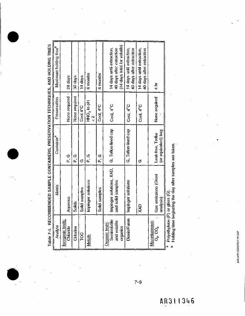
COLUSh-0ZQ_l0XQZ<co"UJrjOzTOUJHZOH<CCUJCOUJCCa.co"CCUJ
IzooUJ_1a.S<CO
AMENDED
•£OoUJCCT-
N.cu•a(2
^~raTJOJIH
Maximum
§njCDCOEQ.
«CDC'5"Soa
§x'ra:s
2ISCO<
CO><COTJCDCM
TJ.1§•CD
CD0
Oa."
Aqueous
>rqanic tests:
Chloride
S
CO;rTJOm
I
1CDO
C5CL
COTJ"5CO
Chlorine
CO1•t
Oorr
O
0
COCDI-coCOTJoCO
O2
months
to
XQ.OnO2 cvjX V
C5CL
in.0Ho
Impinger s
CO
O
CO
o0"3-"oOO
C5Cu"
COCDQ.
COCO
2"oCO
inCO0)2
= gi.2 -2 co" 2 92 | >^ x _oCD 03— u. "JSS CD S§ « 03 COCO CO >,
ra ra-2TJ TJ 3?^r o ST- TT •-_•
ooT
IfO
ZLcooTJCD_C~C_o"331—d
d"<x8" 8-•2 a.3 Eo coCO <"»- TJCD =m oC CO'Q.TJJ §
panic tests:
Semivolatile
and vol
atile
organics
V-O
= Z.2 Bo a11X X(D CI)
3 CDC 3*3 caCO COcTJ TJ•<a- oi- T
O0TT
Q.CO0TJCDC«!Co?CS
CO§3OCOSO)
U0 0£ 2>< 0) CD_, k.— CDC C3 COCO COItT O1— TT
00T
10
o
Q3
1u_1Q
h_
Tt
I
1CD .O
O)i- COCO -Q
"S?H_§CD" 5£iT O"•cl *J51
'S•i2g,CO
'55CO _
• 1^« 81C5 §
scellaneous:
O2, CO2
1
cCDJdJHCDCOCOCDQ.ECOCOwCDS=CO>»
-^ ™»?•~ (Dco •£in ~CO D)?•§O 1=. — . O5CL CD• — • -Q
11ti>(U .—>,TJ
£fn A
7-9
AR31

7.9 SAMPLE DISPOSITION
After completion of the project, the project leader is responsible for providingspecific instruction (in writing) to the sample custodian for final disposition of thesamples.The samples are disposed, returned to the client, or archived by the laboratorysample custodian according to instructions and so noted in the final records.Disposal of hazardous materials are arranged through the MRI Safety and HealthOffice.
7.10 BUILDING SECURITY
Sample security within the laboratories is maintained by the followingmeasures:
t• Building security is controlled by an electronic card entry personal identification
system.• Exterior doors and doors of most controlled access areas within the building are
equipped with card readers (or access code lock systems).• Each member of the staff has a card (or control number) that is coded only for
those areas where their job function requires access.• The department office maintains control over these access codes.
7.11 TRACEABIL1TY OF DATA
Traceability, defined as the ability to reconstruct reported test results backto the original sampling and analysis data and how it was generated, includesthe following:
• Identification and calibration of measurement and test equipment used to collector analyze samples.
MRI-APPLIED\H3S20-D9.QAP 7-10

Use of MRI-issued project record books or equivalently identified data collectionf/*irm<*forms.
Incorporation by reference or full description of. methodologies and technicallynecessary modifications performed.
Sequence (i.e., time, date, and order) that samples were processed or analyzedUn.que identification and cross-reference,of samples and subsequentcomposites, splits, duplicates, reanalysis, etc.Identification of personnel performing the work.
WRI-APPLIED\R3620-09.QAP 7-11
AR3I I 31*8

SECTION 8
CALIBRATION PROCEDURES AND FREQUENCY
Calibration procedures and frequency for sampling and analysis aredescribed in Section 14 and/or in the referenced methods. Calibrationprocedures for process, monitoring instruments are listed in Volume I, Table 2-3.Also, continuous emission monitors will undergo performance specificationtesting as described in Volume I, Section 5.4.
MRI-APPLI£D\R3620-09.QAP
AR3I

SECTION 9
ANALYTICAL PROCEDURES
Sample handling and analysis procedures are described in Section 6 ofthe Trial Burn Plan and are summarized in Tables 3-1 and 3-2 of this QA Plan.
MRI-APPIIED\R3620-09.OAP Q-1
AR3II350

SECTION 10
DATA REDUCTION, VALIDATION, AND REPORTING
10.1 DATA REDUCTION
Data will be produced from three sources, specifically:
Incinerator process conditions during the trial burn.Field measurement data, including: in situ and extractive measuremer;,-sampling records (volumes and duration), waste stream spiking records andobservations.Sample analysis and characterization data.
These data are compiled and used to derive regulatory-requiredperformance values (e.g., ORE for POHCs, particulate emissions, chlorineremoval efficiency), emissions of nonreguiated pollutants (e.g., PCDD/PCDF,metals, etc.) and establish permit conditions for routine operation.
Specific data collection and reduction are described in detail in Section 4(Sampling and Monitoring Plan), Section 5 (Sampling Procedures), and Section 6(Sampling Handling and Analysis) of the Trial Burn Plan. MRI general require-ments for data reduction are discussed below.
10-1
&R3M351

<HQH
R MEASUREMEN
VIISSIONS)
OuJ«gLU Z
P C3«5uj O
1-2D. SPECIFIC OBJ
(STACK GAS
T
1n2
o'to
fa*0.
2§"*
Frequency
c.0'*5i_c
_CD"53TJ
TJ
"53
.x
2
COCD"S£2coQ."coCDH
z
<"z-c,o
One per test
condition;
verif
icat
of system control
and non-
contamination
c1
Jm
z
0C3LO
O o
iiO ajin i-
15One
XAD/filter
(adsorbent)
per t
riburn
CO•S
***
Laboratory
control
sample
(spiked bl
ansample)
QCO coCC .3J^ TJ 0)0-50"v 8.2
5?0toO 0)
g§in ii
IECOCD
I"COCO
UJ 5
co2
_>."5
Surrogates
(iso
topic
labeled compounds
chemically
similar t
otarget POHCs)
z
0LOOJ— . O
v? 35 cjto oIs- CO
After each
initi
alcal
ibrati
on
TJ CO5 o
mISPOHC
check
standa
or au
dit sample
for
independent
verifi
cation
of an
alyti
calibration accuracy
c1> COCO .2210 |-
2 co •
TJc>£•COCD (5*X OQ. 51
1 1
CO CO
14-7
c
To'u.
CD
1 I• CDC TJCO g
t 2CD —CO =CD »^ • co• .2o "co
(0
0)TJ
•35CO
i £CO CD
i !.£ TJ
O =
5 ICO 'go c•C oto • '-5> .1"o £cu «;
oCD », %Q. CO §w jr "§ "c CD£ •» ' '$CO .0 gls£ 1
flR3l1352

TJ0)
O
J2.aca
,o'co'oECL
>>CJ'23s<
Frequency
co
Method
of determinati
X'd"co2
COS"3COCOQ.
173CDt-
<
1
1 ^W rfJT OCO CD 15Will«"§ Is S -(Siiiii
c2iCOJ3 CD COE¥co X,<2,OcR-'5 >j=co•g°58
TJCDO
Q^ry) C corr <u CD^ <» "n5? 5 §•o "53 co•*r -Q co
vPtf8 ^«O CD^ 00 "CO CDr i-
CDQ.
1
2~C(g §J=-G0 TJCO CLU co
CQ
.si*S .s •§'•§.§>g g.|2< §-. 83 X Q. w""8 o5-£i72 .S Q ciStl^I
QCO C corr CD CD
<U "Svp 3 co1* £ CO 'CD COCO -Q CO
vp vPO Q
^ 10'° S"" &£*: g2 i) 3. 0) 9i5 O CO xO o TZ° O ^- 0s M Q.2 CD o3 JS [ CD ST i_ _ CM c j:
CDCLCOcoTJ .*Ii-c-oc^lLJJ CO
CQS
Lab surrogates
<
vg
CLO^ £ro 5^5 0S oo cuIO w
"S w£ CD
8-iCD Q0^
1
Control sample (blank
reagents spiked with
independent standard
of na
tive
PCDD/PCDFs)
<
vPootoT- >.
o §v9 3- CJO 0to co
IS:§'!CDrS* 15< 0
TJ
Independent QC
check
standard (EPA
or ce
rtifie
sPCDD/PCDF
reference
standard)
c1> COCO CD ' .
il^ COS CO
COLLQOCL13QQOQ.
£3_Q
15•cCD^_cCD1ECD.a1CO
.015
o"S3TJ
«jc3JD'c1CD-»_CCDTJ
CD.a1
§
1'£b*_0)"53TJCD.c
1*~in_CD150TJ
1CQ2
14-8
AR3II353

co c w tew « •£ -g
11! Ifsill!
14-9
§
I
AR3I

SECTION 15
REMEDIAL AND CORRECTIVE ACTIONS
Remedial action consists of deliberate measures taken by analyst orproject leader to correct an immediate problem.
Corrective action consists of deliberate measures taken by the analyst,project leader, or the department to eliminate the cause of a problem.
Remedial or corrective actions may be initiated while work is in progress*during technical review, or following an audit. Examples of different types ofproblems and the possible remedial/corrective actions are given in Table 15-1.
The following procedures are used to resolve typical problems that mayoccur during routine sampling and analysis operations. Other unanticipatedproblems should be immediately brought to the attention of the project leader,quality assurance coordinator, or Director, as appropriate for resolution.
MHI.APPLIEDW36ZO-09.CAP 15"1
I355

Tabl9 15'1- REMEDIAL/CORRECTIVE ACTIONS
Problem
Lost, broken, incomplete, or invalid' sample
Contamination of blanks and/or samples
Initial calibration does not meetobjectives (e.g., > ±30% BSD forSV-POHC per Method 8370).
i
Continuing calibration criteria do notmeet objectives (e.g., > ±20% differenceIrom initial calibration RRF).
Missed holding times
NOTE: Holding time requirements mustbe addressed in the planning stages ofthe project in order to schedulenecessary resources or negotiate longerholding times than those listed inSection 7.
Remedial/corrective action
1 . Resample or extend test, if possible.
2. Contact project leader for Instructions.
3. Redo the test If lost sample(s) severely compromise testresults.
4, The sampler, crew chief, analyst, or project leader is requiredto document the problem and actions taken in tha field orlaboratory notebook for inclusion in the project files.
1. Determine source of contamination (e.g., field or laboratory)and which test samples may be affected.
2. Contact project leader for instructions.
3. Report sample results without correcting lor background levelsIf It does not compromise overall project objectives.
4. Correct sample results by subtracting out background levels ifthe source has been identified and the levels are statisticallythe same in multiple blanks.
5. Flag affected data in the report.
1 . Verify that no standards are outliers (e.g., dilution error).
2. Review the standard data to ensure that the analytical systemis in a linear operating range, i.e., no actual deflection in thecalibration curve caused by saturation or loss of sensitivity.
3. Check and adjust instrument operating parameters, asappropriate.
4. Reanalyze the calibration standard(s) if appropriate to meetcalibration criteria (e.g., if an outlying standard was caused bya bad injection).
5. Contact the project leader to proceed with a reducedcalibration range or less stringent acceptance criteria.
6. The analyst must document the problem and actions taken inthe project records.
1. Reinject standard once to confirm results.
2. Rerun an initial calibration it second attempt does not meetcriteria.
3. Contact project leader to see if samples from last acceptablecalibration check need to be rerun. Metals samples areautomatically rerun after recalibratlon.
4. Analyst documents the recaltoration, updates response factors,and notes any reanalysis of samples, (organic analyses only.)
1. Notify project leader immediately of pending missed holdingtimes.
2. The project leader is responsible for immediately notifying theDepartment Director to request additional resources (staff,equipment, overtime, etc.) to meet holding time schedules.
3. If holding times are missed, the analytical staff leader is towrite an internal memorandum to the Director, DQAC, and QAUnit stating the reason for missed holding times, identifying thesamples affected.and listing the number of days samples werepast holding times.
MRI-APPLI£D\(=l3S20-09.QAP 15-2
A R 3 I I 356

Table 15-1 (Contlnund)
Problem
QC data do not meet objectives
Calculation errors
QC check standard does not meetobjectives
Audit sample does not meet objectives
Documentation errors or omissions foundduring technical review or audit
Remedial/corrective action
1 . The technical reviewer or analyst describes the extent andnature of technical problems in a narrative report thataccompanies the data packet.
2. The project leader Is notified.
3. The problem is assessed against project objectives.
4. Test results are appropriately footnoted In the test report toclearly show the nature and extent of the missed QCobjectives.
1. Minor calculation errors may be corrected by the analyst ortechnical reviewer, and so documented In the project recordstraceable to the person, date, and reason for correction.
2. Major calculation errors, or those errors that significantly affecttest results In accuracy or number, are corrected and sodocumented by the analyst or technical reviewer in a memo tothe project leader and file.
3. Calculation errors found during an audit should be handled asa formal corrective action request to the project leader.
1. If initial results of the check standard do not agree, anotherQC check standard is prepared and analyzed.
2. Analyses of samples are stopped until the calibration curve isvalidated by a successful analysis of an independent standard.
3. If the second determination confirms disagreement betweenstandards, then a third independent source of referencematerial is obtained and analyzed to validate the calibrationcurve.
t1. If Initial results of the audit sample do not agree, another audit
sample is prepared and analyzed.
2. Analyses of samples may be stopped until successful analysisof an audit sample.
3. If the second audit sample confirms that results are outsideacceptance criteria, tha problem s evaluated by the projectleader, QAC, and Director to decide if sample analyses shouldcontinue or be repeated.
1 . Documentation errors or omissions found during technicalreview should be corrected by the analyst prior to release ofthe data.
2. Documentation errors or omissions found during an audit areso documented and require a formal corrective action requestand follow-up confirmation by the project leader that theproblem was resolved.
MRI-APPLIEO\H3S20-09.QAP '15-3
AR3!1357

SECTION 16
QA REPORTS TO MANAGEMENT
Any problems that may be found during QA audits are immediatelyreported to the project leader so that corrective action may be taken as needed.
The QA coordinator may assist the project leader by suggesting options tocorrect a problem; however, the project leader is responsible for implementingany corrective action and assuring its effectiveness.
t
The QA coordinator administratively reports to the department directors,who along with MRI corporate QA unit, are copied on all audit reports. Thissystem is intended to provide added assurance that problems are effectivelyidentified and resolved.
After completion of the audit on the Draft Final Report and supportingrecords, the QA coordinator prepares a QA Report summarizing the results of allaudits conducted and assessing the quality of the data relative to the controlcriteria set forth in the test plans.
This QA Summary Report is included as a deliverable with the final TrialBurn Report and distributed internally to MRI management and project staff, asappropriate.
MRI-APPLIEO\R3620-09.QAP 1 6" 1
I358
MIDWEST RESEARCH INSTITUTE425 Volker BoulevardKansas City, MO 64110-2299(816)753-7600
409 12th Street SW, Suite 710Washington, DC 20024-2125(202) 554-3844
401 Harrison Oaks BoulevardGary, NC 27513-2412(919)677-0249
625 B Clyde AvenueMountain View, CA 94043-2213(415)694-7700
National Renewable Energy Laboratory1617 Cole BoulevardGolden, CO 80401-3393(303) 275-3000
A-R3I 1359
10.2 TECHNICAL REVIEW
No data are released to a client or other department without undergoingtechnical review/validation.
Data are initially reviewed by the analyst who formats and collates thedata as required and provides narrative comments appropriate for the review andinterpretation of the test data. For example, the following test and QC resultsshould be filed for review:
• narrative summary'• test results• field test records• QC records (e.g., calibration of sampling equipment)• blank results• surrogate recoveries *• spike recoveries• initial calibration • ,• continuing calibration• precision of replicate analyses• example calculations• procedures used• detection limits (including derivation and values)• dates of collection, receipt, extraction, and analysis• sequence of analysis• reagent and standard preparation records• source of other reference standards and materials• instrument operating parameters >•
A secondary technical review of the data is performed by the task leaderor laboratory manager and/or other qualified scientist as appropriate. Thesecondary reviewer should include evidence of the review (e.g., check marks,recalculations, etc.) that show which data points were checked. Finally, the
MRI-APPUED\R3S20-09.QAP . 1 Q'2
AR3II360

second reviewer should sign and date the cover page of the data packet or therecord that was reviewed.
10.3 DATA VALIDATION
In situ measurements are validated by demonstrated acceptable posttestleak checks and calibration verifications according to the reference method used.
Analysis data may be validated according to defined criteria by asecondary reviewer (preferable) or by the analyst. At a minimum, data arevalidated according to the following criteria (Table 10-1) (Additional method^specific criteria or project requirements may apply.)
10.4 DATA REPORTING ^OThe trial burn test data will be reported according to Section 7 (Reporting
of Results) of the Trial Burn Plan.
Analysis reports and data submittals must be reviewed and approved bydepartment management prior to release to the project leader.
Reports and supporting data are subject to a quality assurance reviewand/or audit prior to release, to the client.
MHI-APPLI6DW3620.09.QAP 1 0"3
A R 3 I I 3 6 I

Table 10-1. MINIMUM REQUIREMENTS FOR DATA VALIDATION
1 . Are sampling records complete and traceable?2. Are calibration and recheck records for sampling equipment
provided and within method criteria?3. Were all appropriate QC samples included with the
analytical batch and reported with the sample results?4. Were routine tuning, calibration, and inspection of analytical
instrumentation documented and performed prior toanalyses?
5. Were initial and continuing calibration criteria met?6. Do method/reagent blanks confirm no background
contamination?7. Are surrogate recoveries within criteria?8. Arc qualitative sample results (e.g., retention times, mass
spectra, isotopic ratios) consistent with standard data?9. Are sample data within the calibrated range of the
instrument?1 0. Are chromatograms or other raw data consistent with
computer-generated quantitation reports?1 1 . Has the accuracy of intermediate data manipulations,
transcribed numbers, and/or final reported results beenverified?
12. Are reference standards, instrumentation, sampleidentification, analysts, methodology, and sequence ofprocessing clearly identified and traceable in the projectrecords?
1 3. Have all lost data or corrective actions been documented?(For example: loss of sample, reanalysis, redilutions,additional cleanup steps, alternative calculations, etc.)
14. Have all data that do not meet the validation requirementsbeen flagged accordingly?
1 5. Are the data reported in the correct units? (For example,"ppm" should not be used without specifying volume ormass units; "M-g/g" are preferred units for data reportingrather than "ppm."
Yes No N/A
,'=|.APPllED\R3S20-C9.aAP . 10~4
AR3I1362
*.
Any report or data which has not been completely validated or auditedmay only be reported to the client by approval of the Department Director andmust be clearly stamped "preliminary" or "draft."
Data corrections or technical revisions (noneditorial) to reported data mustbe technically reviewed by the project management and approved by the depart-ment management. The Director and the QA Coordinator must be notified ofmajor revisions or data corrections to final reports so that corrective actions maybe taken as appropriate.
The report to the client should note if suspect data points were examinedas part of the technical review.
10.5 SIGNIFICANT. FIGURES
The significant figures in a number comprise all those digits whose valuesare known with certainty plus the first digit whose value is uncertain.
Zeros between nonzero digits are significant (e.g., 5.003 has foursignificant figures); zeros are not significant when used to indicate orders ofmagnitude (e.g., 0.00035 and 35,000 have two significant figures).
Results are calculated using significant figures and reported as roundedvalues to the number of significant figures warranted by the demonstratedprecision and accuracy of the method.
Numbers ending with 5 or higher are rounded up; numbers ending with4 or less are truncated.
MRI-APPUEDW3620-09.0AP 1 0'5
A.R3I I 363

10.6 REJECTION OF DATA
When a data set includes an outlying result that appears to differexcessively from an average value, the decision to retain or reject the suspecteddata point may need to be made.
Data that fail some or all associated QC criteria may still be reported asestimated values; however, all such data should be appropriately footnoted in theproject records and reports as to the reasons for qualification.
The following steps should be taken before data are rejected:
Estimate the precision that can be reasonably expected from the procedure, todetermine if the result is questionable.Reexamine all data related to the sample result (e.g., sample preparation,analysis logs, etc.) to see if a gross error has affected its value.Repeat the analysis if sufficient sample and time are available.Apply the Q-test or other appropriate method to see if the suspect data may berejected on statistical grounds.
• If the data cannot be rejected on the preceding points, report the value asdetermined.
10.7 PROJECT CLOSURE
After a project is completed and the deliverables are finalized, the ProjectLeader is responsible for collecting and indexing project files according to MRIQA Guidelines and MRI Corporate Policies and Procedures.
1 0"6
AR3I I 361*

SECTION 11
INTERNAL QUALITY CONTROL CHECKS
Procedural and calibration QA/QC requirements are defined by the TrialBurn Plan and by the referenced methods. Specific QC checks for estimation ofaccuracy, precision, and for evaluation of technical completeness are presentedin Section 14.
MRI-APPLIEO',R3620-09.QAP 11-1
AR3I I365

SECTION 12
AUDITS
Audits will be independently performed by the project QA coordinator inorder to verify:
'• Absence of systematic errors.• Compliance to authorized test plans and methodologies.• Adequacy of supporting documentation.• Accuracy and derivation of reported test results.
Three types of audits, described below, will be conducted during thecourse of the project.
12.1 TECHNICAL SYSTEMS AUDIT
Critical procedural areas of project activities will be targeted for verifyingcompliance to authorized methods, procedures, and test plan requirements.These systems audits will primarily be conducted early in the project and mayoccur during test preparation activities, during actual field sampling (field audits),and/or during sample analysis.
MRI.APPLieOW3620-09.QAP 12~1
AR3!I366

12.2 PERFORMANCE EVALUATION AUDITS»•
Performance evaluation (PE) audits involves submitting simulated samples, or standards into the analytical flow in order to verify the accuracy of theanalysis.
PE samples are prepared independently under the direction of the QAcoordinator and submitted "blind" or at concentrations undisclosed to the analystuntil values are reported.
The audit report consists of reporting the accuracy of the reported valueversus the certified or reference value, using the form shown in Figure 12-1.
12.3 AUDIT FOR DATA QUALITY
A final audit is performed after ail test results and supporting data havebeen compiled and prepared as a draft final report for internal MRI review andclient comments.
This data audit includes:
• Verifying the completeness of records and data relative to the Trial Burn and QAPlans.
• Assessing the validity of the analyses relative to the QC data (e.g., calibrations,surrogate recovery, etc.) generated during the sample analyses versus QCacceptance criteria.
• Assuring the accuracy and traceability of the data by auditing representative testdata from sampling through analysis and its derived values (e.g., ORE values).
MRI-APPLIED\R3S20-09.QAP 12-2
AR3II367

12-3
AR3II368
cnc"CoaCU
TJCCC
0)3cr
a.cn
ucra
otcua.
CU1_Z!cnIT'

SECTION 13
PREVENTIVE MAINTENANCE
MRI has an on-site Instrument Services group for maintenance and repairof test equipment. MRI also routinely uses outside contractors for regularmaintenance (e.g., balances) services.
In addition, MRI Instrument Services stores replacement parts, wherepossible, to prevent downtime. Manufacturer's service representatives are alsocontracted for major instrument repairs when necessary.
Preventive and routine maintenance for test equipment is covered ininstrument SOPs or in accordance with manufacturer's recommendations (i.e.,instrument manuals).
Daily maintenance (such as replacement of injector septa, etc.) is coveredin instrument SOPs.
Inoperative equipment is tagged as nonusable until repairs are performed.
Logbooks are maintained next to each instrument to record usage,maintenance, and repairs.
MRI -APPLI ED\R3620-09.0AP 13-1
AR3II369

SECTION 14
SPECIFIC PROCEDURES USED TO ASSESS DATA QUALITY
This section and the associated tables describe the specific proceduresthat will be used for estimation of accuracy and precision. The accuracy andprecision objectives for the test parameters shown in the tables are primarilybased on information in the EPA handbook titled "Quality Assurance/QualityControl (QA/QC) Procedures for Hazardous Waste Incineration" ,(EPA/625-6-89/023 Jan 1990) or on information given in the specific analytical methods.Specific analytical methods are identified in Tables 4-1 and 4-2 of the Trial BurnPlan (Volume I) and in Tables 3-1 and 3-2 of this Volume II.
EPA Method 5 and related sampling methods are primarily validatedthrough initial and posttest calibrations and procedural elements of the method,such as documentation of acceptable leak checks, proper traversing, and place-ment of sampling probes, etc. Table 14-1 lists validation criteria for thesemethods.
Tables 14-2A through 14-2E list QC checks and objectives to estimateaccuracy and precision for analyses relevant to the miniburn and the Trial Burn.Completeness of the test data will be evaluated based on these QC parameters.
An extra set of samples of waste feed, fly ash, and bottom ash will betaken in one run, for analysis by USACOE's QA laboratory, as noted inTable 3-2.
MRI-APPLIED',R3S20-09.QAP 14-1
A R 3 I I 3 7 0
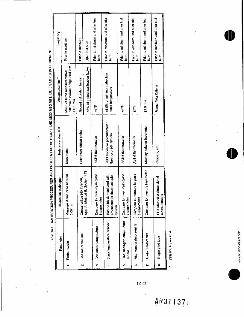
zUJ
Q.13OUJaza.S
inQ
IFIED METHO
Qi1
S1i£11i
BRATION PROCEDURES
ft
3U
t
1^o>3£
3-g3cr£LL
^
I8"3L
•2
U)
1
Calibration technique
^(D
Paramet
c
ac'£0
o£$
elIiIira cCD 0)E u
a .35 o p— (J c
ra S *^CD S O5 '-3 vi
SCD
2if
Measure diameter to
neares
0.001 in
(Dai2a.
-
E3_a'c121a.
°Jca
Record
calibra
cJ21
S
o0ra
12.-a1
±5% ol
pretesi
CD_oso81"8Is.s3
_»s'sgSo m"2,-B
ll
SI
<D
1
2oEraCJ
CM
ro•cw
'ra•0
iE3,-sc1o
iiQ- .a
u.0
5CD
FM therm
<
</>
Compare to me
rcury-in-glas:
thermometer
m32SISI
raO
ri
raS_"ra•arag5cI2
il
3"I
1
1 211•= o£ a.
3«cN in o4J^
S<u11 iIs.0) W
If2 yCD <DZ £
Heated
block monitored
with
potentiometer thermocouple
system
w8c«iw8.CD
1in
*
raS.2"raT3iE3
1E0
0 |
a.o
CD
1O
rM thenn
S
M
Compare to me
rcury-in-glas;
thenmometer
*
£3"SCD
£
iC L.
!•U. a
UJ
.Uc
Sra
1£
-9.SE0
Ii
LL.o
fe1
I
<
cn
Compare to me
rcury-in-glas
thermometer
oc812CDa.
JLU
co
(TJC
1raT3cra
•3c's2
II
±2.5 mm
Q?ffl
iC
1
2CD
i2ra
CD
°2raQ.
O
S0)
SS2CD
^
^
ra_cw2"aT3§|.QCi2
II
ra•c2•HOCM
1
ffl
a"CDQ.
1
EPA Method 2 dimensional
measurements
2
S"Iw
*
14-2
A R 3 I I 3 7 I
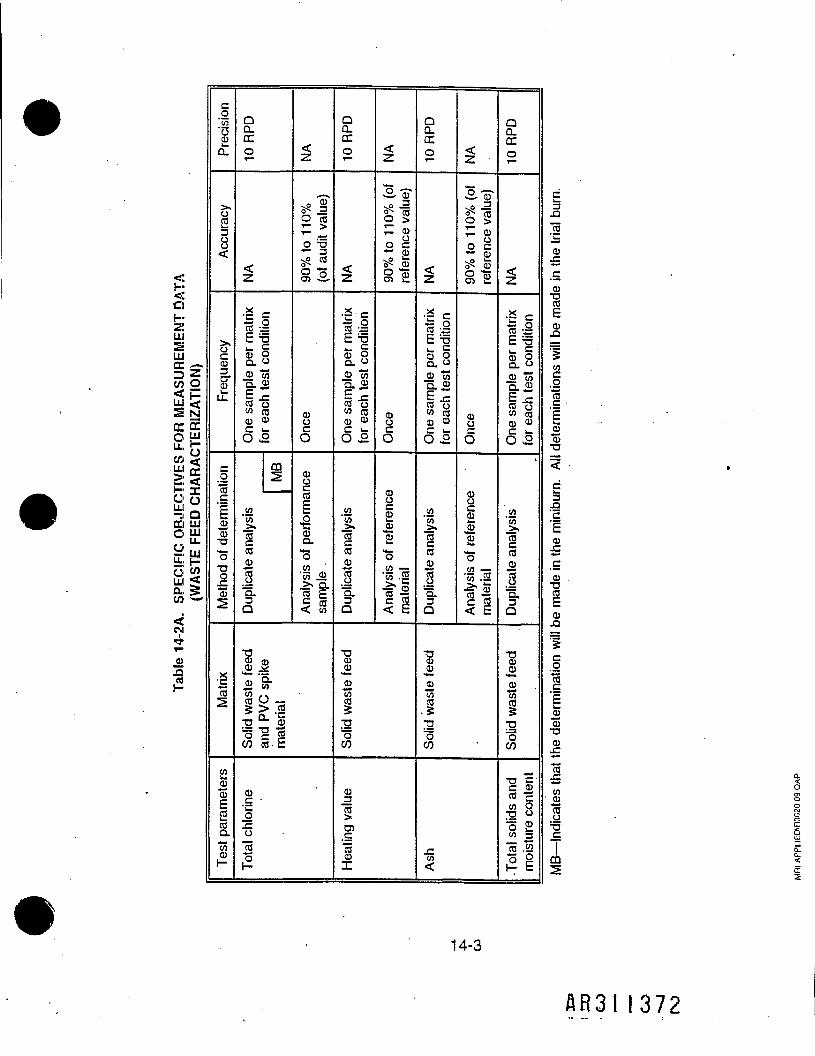
<QH•ZiUlIE*
Ula: .-.
FOR MEASU:
ITERIZATION
UJ <> 5
ft. S
PECIFIC OBJECT
(WASTE
FEED CU
•403.a.2
c,0-TT
03ct
^38<<
o03
1
§
Method
of determinal
75
20303
1COQ.tn03
QQ.CCO
J»
•z.
•Igco ~ETJu. C-g.803 05"5. 03
co "ocn JoCD 03
m2
_cn'co"coCOCU
1Q.
Q
•z.
o "§"o "5HO "O"o JOo^
°~
03o603OCO
10.
"3.2.><~5.ra E% a< CO
03 CD03 J2
s'S-3o_ 'n *C
TJ <DO c £2co cc-E
03'CZ_ou157
h
QQ.CC0
^
•z.
'!'•!E TJ,_ CS. 803 to"5. £.CO Ocn coCU 03
60
_cn'35
tCO03
S§•Q
£
&-Jo 15^ 030 C*o Sio 03O5 2.
03
o
Analysis of reference
material
•o03.jj_03tniTj"oCO
03
"co>ra7503I
QQ.CCO
^
~z>
•l§CO ~E'-Dg.103 05Q.
l-gCO COCD 03
6°
'co
CO03
1Q.
Q
•z.
^r 3^ §^ 030 g^ S? 030 jO) SH
03CJ
CD
Analysis of reference
material
03£:
_CD
In.iTJOCO
/—In
QQ.CCO
•z.
xisjL. C03 OQ. °03 05
I-co ocn co03 03
•
cn'§,CO
CO03
1Q.
Q
1_03Ini1OCO
•ifCO c-o 8o SJ"co ."5^5 ^h- s
14-3
C3
.2*w03
03|
I1CO
.0
CD03TJ
C
.a'c'E03
C
03-Q
1
O
03"03TJ03
i *s §s £c fi^ UJ
AH3I1372
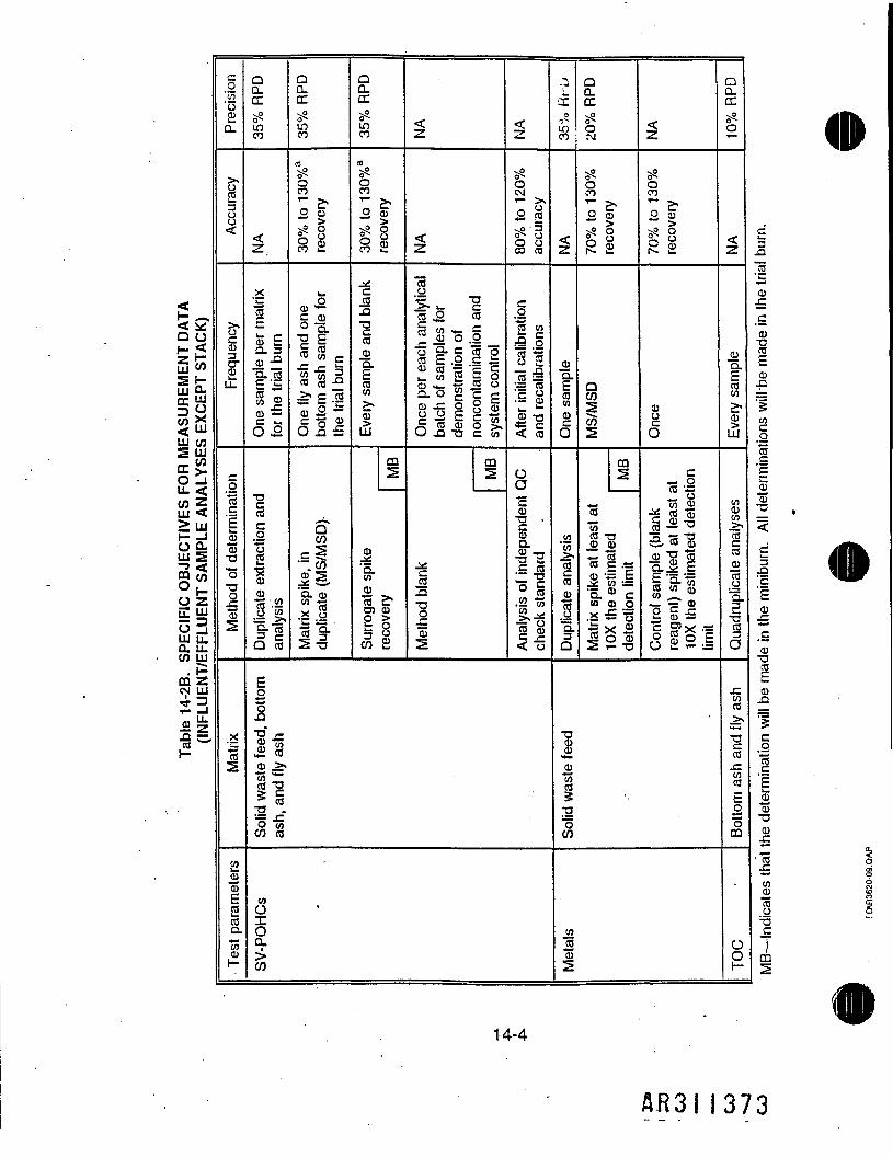
ASUREMENT DATA
EXCEPT STACK)
LU CO
_ COCC >.0 _JLL. <cozUl <>UJ
PECIFIC OBJECT!
FFLUENT SAMPL
CO UJ
CD ZOJ LU
3 "•2£~
.0'in'o£CL
oi
Frequency
_o7512.03TJ"75TJ
"53
-"w1
203'cu
2COCLTo031-
QQ.CC55LOCO
Z,
x
cu £Q. 3cu -aa. ca£ 'is
C wO £.
COc.07350303
S-o?s-lQ ca
QQ.CCvO
LOCO
ao
J2O CD
J oo^ Oo (DCj u.
I <"° .
»-iico co -0^ E -S,1 75 2O J5 £
5"CO
CL <D
•c J7t 9-2-S
QCLCC0LOCO
a
OCO
o
iCO
*
Every sample
and bla
Surrogate spike
Eo1" -Cs t«z. CO03 >s
Ii* «TJ'S-gCO CO
05OI0CL1
CO
03i
CD5
recovery
<cz
z
"5o
Once
per each
analyti
batch of samples
for
demonstration of
noncontamination and
system
control
m
Method
blank
z
v«QCM
O cO*^ wo^ O§0co
After
initia
l calibration
and recalibrations
OO03
"cAnalysis of indepe
check standard
,i_0
U5CO
1
03a.(3CO03
CD
01'cn
tco
1a.Q
QCLCCob
QCO
"o 1X5>5 &fel
aCO
S
737n
CO
CO TJ03 03
illCL Cm o> o'Ij'gto o "S2 i- TJ
T5033
_031oiTJ"oCO
05CO"CD2
z
oCO
'o cS*ii
03
6
75 •-!~ cC QJ§ .32 T3
ill
QQ.CCvO
b
z
03Q.
03LU
CO03CO>,
Quadruplicate ana
f~COco
TJCCOcnCOEo73CO
Ooh-
flfeflllBUr
C5.S03
03
I03
105
.O
75e'p
"cu-a .^
1 *03.e
03TJ
03.0
1CO
11"STJ
£•S 5.C oi
CO gCD S75 5u &T!c
1. • kL.
14-4
AB3II373

TJ03
OO,
CQ
.2
.2'35'oEQ.
cj-23CJO<
>.P:03
crd:
c..273r.
_03"03TJ"3TJo"o!
_x' wTo2
£03"03E2aTo03H
<
<
03T5u.Tn C
to demon:
itaminatio
II
Extraction
fluid
blank
QQ.CC2SS
500CO
7 *O (jj^5 §£ oO a,r*» t-
QCO
CO2=O
y2X03CL0
'TS5Q.03
1
.cCOCO_>%*z•gCOJZ.05CO
E075CQ
cnCO702O._j£
<
"00CO
o—goCO
03
I"cocn
1LU
m2
CO_03
ra og£3 COW TJ
P> 0J?Q. 03CO 0.
J=O5co_>.
iCOj:05CO
E075CQ
05OO>CO
QCLCCvP0inCO
a900CO*~ >•o Sg8S £_x'w75Ecu £CX. 303 -a§••=s 5CU —00
_075.0"5.TJ.C
J'5.Q03 CO.*. 273^/52s
<
<
03O
8Method
blank
QCLCCp0mCO
<
1
03
c§Duplicate analysis
<
0OCJ
3S«S
_03
COcn
1LU
0,±Spike with surrogates
per Method 8260
-CinCO_>,
icoj= 'cnCOE£oCQ
cn0O>
QQ.CCsP0
8
0oCJ
2V?1s£*W
ToEZ £Q. 3_o>-aa. caE i«5 05 OJ03 —
6=<2
03
Matrix spike, in du
plical
(MS/MSD)
<
<
03O
.0
Method
blank
QCLCCx?tf-mCO
^
03
gO
Duplicate analysis
v° v? _:o^ tf^ CO O • 3•CO CJ jgr- T—o o .2*— *-" tsP NP *"*o 6s* Q)00 £cO h- "—•75 "75 -£03 03 03ra ra ^c c $222 £03 03 2•B -B _.1.1 1^ < cn"22 .1cu cu ••=c c g03 03 .£ra ra f=cu 03 irSr c cuCO CO aj03 03 "O73 To 5ra ra <2 233 £05 CO 3.0 .0 &
03 03 EQ. Q. 03CO 05 _£
"g-g cCO CO '-03 03 0l_ L. TJ
v2 £ 5° CD 03CJ CJ J200 CO =5TJ TJ 'gO OJ= J= CTS TS • -2^ * ts.<> S rak. L. ._03 03 CQ. Q. Ecn cn 3311 "0= —— 0
£• &• €03. 03 _> > COO O £Z03 03 in*- w 032 S Toco co .0ra ra T-J22 cw b_ *-r3 3CO CO QJjCS J3 2
14-5
AR3II37^
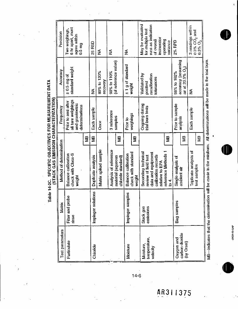
QHZs z"
FOR MEASUREI
ARACTERIZATIO
cn TLU O>t— Q
Ul CO^ COCQ S5O LU
c3 (3Ul CL :£w <0 COIN — '
_aj
S
0'co'003CL
«o
Frequency
co75
0375TJ"75TJO
713
.x
en_03"32coQ.T/5
cn" 7nfi =-C • '?O5 t "'03 S 'g _> Ii O5> CO CD Cn w 035 -^ ra101— CD CO O
£.2?
T3 I
||O cfl+l To
i_ CO
Prior t
o and
aftei
all tare weighing
and gravimetric
determinations
CO2
Balance calibration
check
with Class-S
weight
03foQ.TJiLL -c
03To3
COQ.
QCOCCmC\4
Z
03
I
%
OcoLU
CO2
cn'co
tco03
1CLQ
z
5?OCJ
O 03vP O
O CDOJ u.
03O
6
03
Matrix sp
iked sampi
z^ ^
3
§£> 032 gr- 03
3 <£.
Si
3 reference
samples
CO2
cu
Analysis of
referenc
material (aqueous
chloride standard)
03S•~"3oen03racf
03TJ
5
6
<<"Z-
ISCO
1To"75 «-
r- 'CD-H 3
Prior to
weighings
CD2
Balance calibration
check
with standard
weight
CO03Q.ECOcn03ra.£
03Jj7J3
T) c3 _ OCO co «== s.S> 03 TJ ^CD "5..S = 2 ra ...cu & co 2 £ . S S
co w c _ 'o Q. co2 .2 ,_ 15 .£ o >
^ JenTJ 't5 03B To 2 °75 03 r° 9TJ *-* "rt! 2
ra.£ £J
Ii0 -Qra —C COOS
co2Secondary
technical
review
of fi
eld te
stdata and equipment
calibration records
relati
ve to
EPA
reference Methods
'.to
4.
cn 05CO Cra.o^ 'coCJ COfllCO 03
£lit•b *•» >
3.CC5?CJ
ra_c
^0 3d1c> w -S^g5 IIS co 'co
03•Q.CO03
a-SL_ J5j*.2 CB-Q. CO
m2
Single an
alysis of
ambient air
c
ifW fvtcn f~\
CO vP - OQ) O 0sZ- CO COco d d
z
.22'
coCO
1LU
CD2
'"7503'03
fenra £CD a-1° §.ii O3•g-To
0503Q.
CO05
C?CO
03
1*
ijilit
Eja'103
c03TJME
S
^terminations
will 1
-53—<
C3
'5E03
03TJ
03
1CO
1'103'aJ
CU
1COJUToo1CO
14-6
AR3II375