Appendix A Development Ideology - Springer978-1-84800-038-4/1.pdf · 132 Appendix A Development...
26
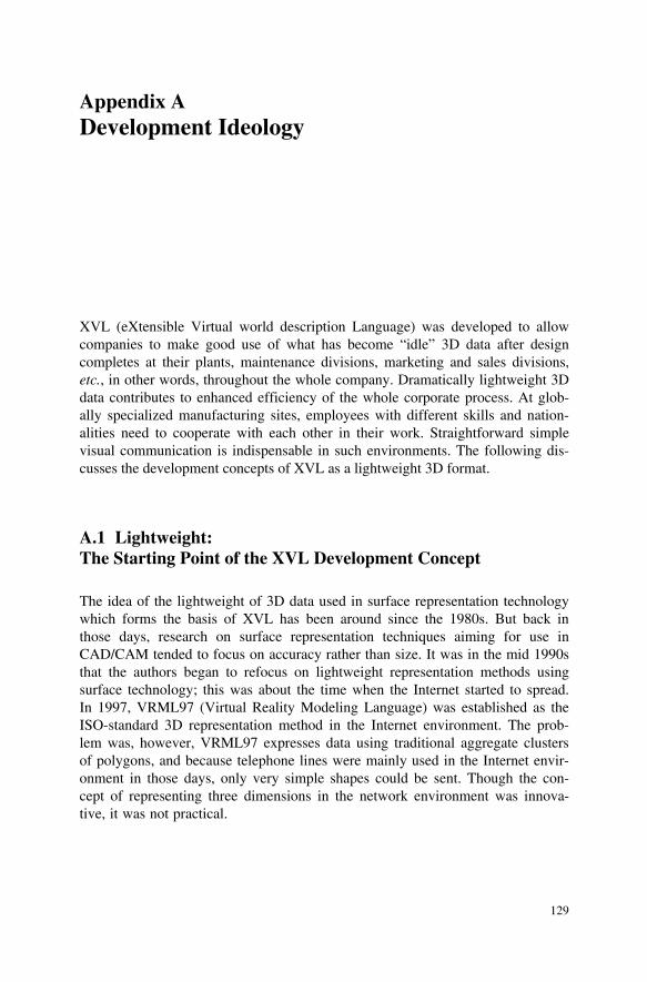
129 Appendix A Development Ideology XVL (eXtensible Virtual world description Language) was developed to allow companies to make good use of what has become “idle” 3D data after design completes at their plants, maintenance divisions, marketing and sales divisions, etc., in other words, throughout the whole company. Dramatically lightweight 3D data contributes to enhanced efficiency of the whole corporate process. At glob- ally specialized manufacturing sites, employees with different skills and nation- alities need to cooperate with each other in their work. Straightforward simple visual communication is indispensable in such environments. The following dis- cusses the development concepts of XVL as a lightweight 3D format. A.1 Lightweight: The Starting Point of the XVL Development Concept The idea of the lightweight of 3D data used in surface representation technology which forms the basis of XVL has been around since the 1980s. But back in those days, research on surface representation techniques aiming for use in CAD/CAM tended to focus on accuracy rather than size. It was in the mid 1990s that the authors began to refocus on lightweight representation methods using surface technology; this was about the time when the Internet started to spread. In 1997, VRML97 (Virtual Reality Modeling Language) was established as the ISO-standard 3D representation method in the Internet environment. The prob- lem was, however, VRML97 expresses data using traditional aggregate clusters of polygons, and because telephone lines were mainly used in the Internet envir- onment in those days, only very simple shapes could be sent. Though the con- cept of representing three dimensions in the network environment was innova- tive, it was not practical.
-
Upload
phungquynh -
Category
Documents
-
view
220 -
download
0
Transcript of Appendix A Development Ideology - Springer978-1-84800-038-4/1.pdf · 132 Appendix A Development...
129
Appendix A Development Ideology
XVL (eXtensible Virtual world description Language) was developed to allow companies to make good use of what has become “idle” 3D data after design completes at their plants, maintenance divisions, marketing and sales divisions, etc., in other words, throughout the whole company. Dramatically lightweight 3D data contributes to enhanced efficiency of the whole corporate process. At glob-ally specialized manufacturing sites, employees with different skills and nation-alities need to cooperate with each other in their work. Straightforward simple visual communication is indispensable in such environments. The following dis-cusses the development concepts of XVL as a lightweight 3D format.
A.1 Lightweight: The Starting Point of the XVL Development Concept
The idea of the lightweight of 3D data used in surface representation technology which forms the basis of XVL has been around since the 1980s. But back in those days, research on surface representation techniques aiming for use in CAD/CAM tended to focus on accuracy rather than size. It was in the mid 1990s that the authors began to refocus on lightweight representation methods using surface technology; this was about the time when the Internet started to spread. In 1997, VRML97 (Virtual Reality Modeling Language) was established as the ISO-standard 3D representation method in the Internet environment. The prob-lem was, however, VRML97 expresses data using traditional aggregate clusters of polygons, and because telephone lines were mainly used in the Internet envir-onment in those days, only very simple shapes could be sent. Though the con-cept of representing three dimensions in the network environment was innova-tive, it was not practical.
130 Appendix A Development Ideology
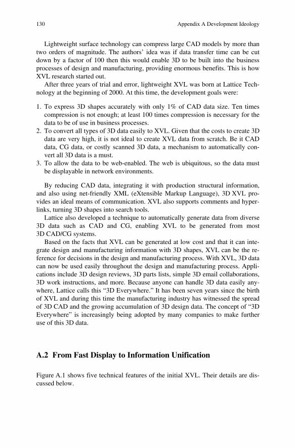
Lightweight surface technology can compress large CAD models by more than two orders of magnitude. The authors’ idea was if data transfer time can be cut down by a factor of 100 then this would enable 3D to be built into the business processes of design and manufacturing, providing enormous benefits. This is how XVL research started out.
After three years of trial and error, lightweight XVL was born at Lattice Tech-nology at the beginning of 2000. At this time, the development goals were:
1. To express 3D shapes accurately with only 1% of CAD data size. Ten times compression is not enough; at least 100 times compression is necessary for the data to be of use in business processes.
2. To convert all types of 3D data easily to XVL. Given that the costs to create 3D data are very high, it is not ideal to create XVL data from scratch. Be it CAD data, CG data, or costly scanned 3D data, a mechanism to automatically con-vert all 3D data is a must.
3. To allow the data to be web-enabled. The web is ubiquitous, so the data must be displayable in network environments.
By reducing CAD data, integrating it with production structural information, and also using net-friendly XML (eXtensible Markup Language), 3D XVL pro-vides an ideal means of communication. XVL also supports comments and hyper-links, turning 3D shapes into search tools.
Lattice also developed a technique to automatically generate data from diverse 3D data such as CAD and CG, enabling XVL to be generated from most 3D CAD/CG systems.
Based on the facts that XVL can be generated at low cost and that it can inte-grate design and manufacturing information with 3D shapes, XVL can be the re-ference for decisions in the design and manufacturing process. With XVL, 3D data can now be used easily throughout the design and manufacturing process. Appli-cations include 3D design reviews, 3D parts lists, simple 3D email collaborations, 3D work instructions, and more. Because anyone can handle 3D data easily any-where, Lattice calls this “3D Everywhere.” It has been seven years since the birth of XVL and during this time the manufacturing industry has witnessed the spread of 3D CAD and the growing accumulation of 3D design data. The concept of “3D Everywhere” is increasingly being adopted by many companies to make further use of this 3D data.
A.2 From Fast Display to Information Unification
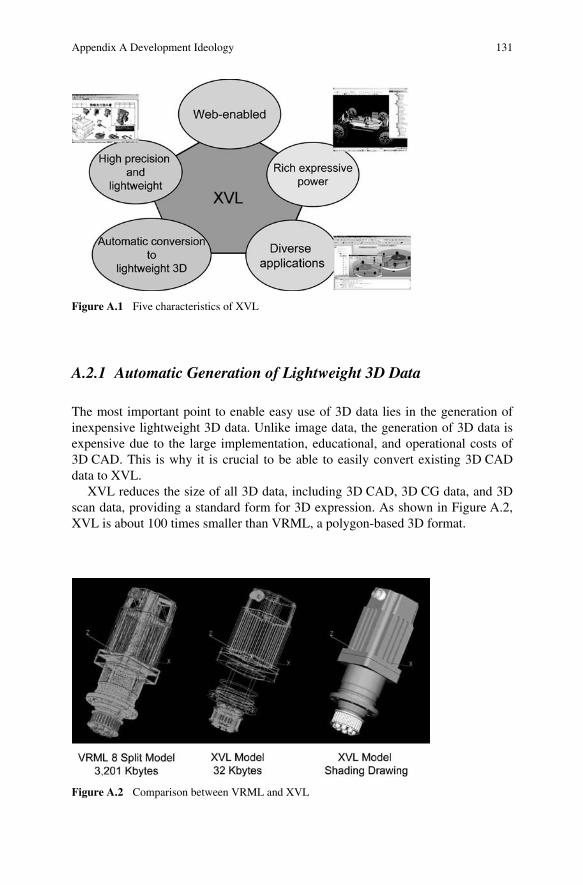
Figure A.1 shows five technical features of the initial XVL. Their details are dis-cussed below.
Appendix A Development Ideology 131
A.2.1 Automatic Generation of Lightweight 3D Data
The most important point to enable easy use of 3D data lies in the generation of inexpensive lightweight 3D data. Unlike image data, the generation of 3D data is expensive due to the large implementation, educational, and operational costs of 3D CAD. This is why it is crucial to be able to easily convert existing 3D CAD data to XVL.
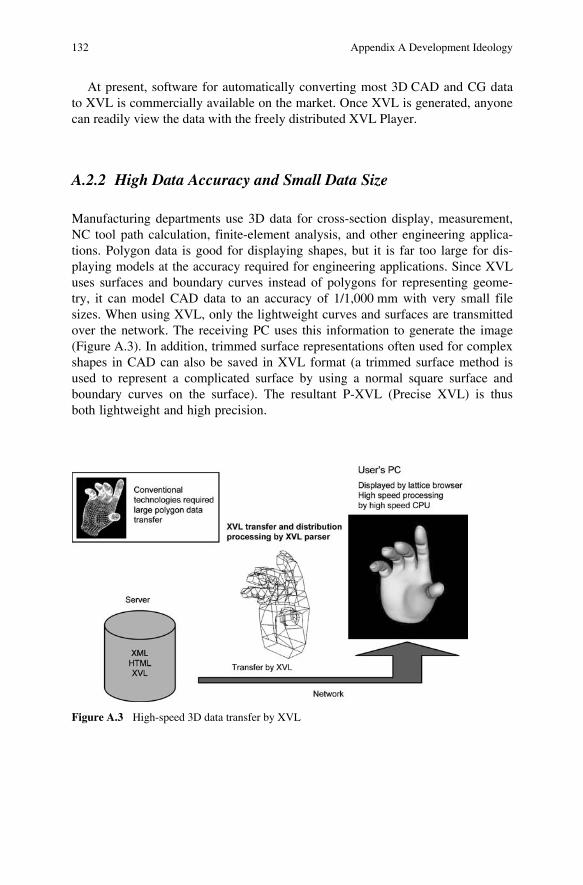
XVL reduces the size of all 3D data, including 3D CAD, 3D CG data, and 3D scan data, providing a standard form for 3D expression. As shown in Figure A.2, XVL is about 100 times smaller than VRML, a polygon-based 3D format.
Figure A.1 Five characteristics of XVL
Figure A.2 Comparison between VRML and XVL
132 Appendix A Development Ideology
At present, software for automatically converting most 3D CAD and CG data to XVL is commercially available on the market. Once XVL is generated, anyone can readily view the data with the freely distributed XVL Player.
A.2.2 High Data Accuracy and Small Data Size
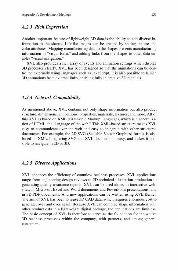
Manufacturing departments use 3D data for cross-section display, measurement, NC tool path calculation, finite-element analysis, and other engineering applica-tions. Polygon data is good for displaying shapes, but it is far too large for dis-playing models at the accuracy required for engineering applications. Since XVL uses surfaces and boundary curves instead of polygons for representing geome-try, it can model CAD data to an accuracy of 1/1,000 mm with very small file sizes. When using XVL, only the lightweight curves and surfaces are transmitted over the network. The receiving PC uses this information to generate the image (Figure A.3). In addition, trimmed surface representations often used for complex shapes in CAD can also be saved in XVL format (a trimmed surface method is used to represent a complicated surface by using a normal square surface and boundary curves on the surface). The resultant P-XVL (Precise XVL) is thus both lightweight and high precision.
Figure A.3 High-speed 3D data transfer by XVL
Appendix A Development Ideology 133
A.2.3 Rich Expression
Another important feature of lightweight 3D data is the ability to add diverse in-formation to the shapes. Lifelike images can be created by setting texture and color attributes. Mapping manufacturing data to the shapes presents manufacturing information in “visual form,” and adding links from the shapes to other data en-ables “visual navigation.”
XVL also provides a rich array of events and animation settings which display 3D processes clearly. XVL has been designed so that the animations can be con-trolled externally using languages such as JavaScript. It is also possible to launch 3D animations from external links, enabling fully interactive 3D manuals.
A.2.4 Network Compatibility
As mentioned above, XVL contains not only shape information but also product structure, dimensions, annotations, properties, materials, textures, and more. All of this XVL is based on XML (eXtensible Markup Language), which is a generaliza-tion of HTML, the “language of the web.” This XML-based structure makes XVL easy to communicate over the web and easy to integrate with other structured documents. For example, the 2D SVG (Scalable Vector Graphics) format is also based on XML. Integrating SVG and XVL documents is easy, and makes it pos-sible to navigate in 2D or 3D.
A.2.5 Diverse Applications
XVL enhances the efficiency of countless business processes. XVL applications range from engineering design reviews to 2D technical illustration production to generating quality assurance reports. XVL can be used alone, in interactive web-sites, in Microsoft Excel and Word documents and PowerPoint presentations, and in 3D PDF documents. And new applications can be written using XVL Kernel. The aim of XVL has been to reuse 3D CAD data, which requires enormous cost to generate, over and over again. Because XVL can combine shape information with other product data in a lightweight digital package, the applications are limitless. The basic concept of XVL is therefore to serve as the foundation for innovative 3D business processes within the company, with partners, and among general consumers.
134 Appendix A Development Ideology
A.3 New Upgraded XVL Technology Reduces Memory Consumption
With the growing use of 3D CAD data in the manufacturing industry, more and more companies are generating detailed 3D models. The data volume is increasing rapidly. For example, if all the parts of a car were to be expressed as precise 3D models, the total data volume would exceed 20 GB. It is impossible to display such models on standard PCs, where the memory size is usually limited to 2 GB. Sometimes models that are only 100 MB take several minutes to read and display, making them impractical for use.
A new version of XVL solves this problem. Through a new innovative surface technology which reduces memory consumption, XVL is able to display such models almost instantaneously. At Lattice, we call this XVL display technology V-XVL (Visual-XVL).
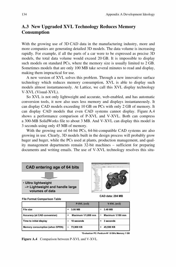
So XVL is not only lightweight and accurate, web-enabled, and has automatic conversion tools, it now also uses less memory and displays instantaneously. It can display CAD models exceeding 10 GB on PCs with only 2 GB of memory. It can display CAD models that even CAD systems cannot display. Figure A.4 shows a performance comparison of P-XVL and V-XVL. Both can compress a 300-MB SolidWorks file to about 3 MB. And V-XVL can display this model in 3 seconds using only 45 MB of memory.
With the growing use of 64-bit PCs, 64-bit-compatible CAD systems are also growing in use. Clearly, 3D models built in the design process will probably grow huger and huger, while the PCs used at plants, production management, and qual-ity management departments remain 32-bit machines – sufficient for preparing documents and writing emails. The use of V-XVL technology resolves this situ-
Figure A.4 Comparison between P-XVL and V-XVL
Appendix A Development Ideology 135
ation as it allows inexpensive PCs to display gigantic 3D data. Even the free XVL Players can display these enormous models. This means that, by converting the data to XVL, massive 3D models designed on 64-bit PCs at leading companies can be used by small subcontractors who only have 32-bit PCs.
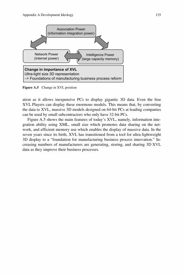
Figure A.5 shows the main features of today’s XVL, namely, information inte-gration ability using XML, small size which promotes data sharing on the net-work, and efficient memory use which enables the display of massive data. In the seven years since its birth, XVL has transitioned from a tool for ultra-lightweight 3D display to a “foundation for manufacturing business process innovation.” In-creasing numbers of manufacturers are generating, storing, and sharing 3D XVL data as they improve their business processes.
Figure A.5 Change in XVL position
137
Appendix B Overview of XVL Products
This appendix introduces the main XVL applications that are available on the market. The easiest way to use XVL is to install the free “XVL Player” and start viewing models. You can download XVL Player from www.lattice3d.com, then see the demo page to view XVL models. Companies using XVL for communica-tion often have XVL Player installed on every computer.
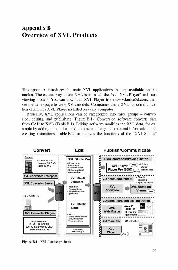
Basically, XVL applications can be categorized into three groups – conver-sion, editing, and publishing (Figure B.1). Conversion software converts data from CAD to XVL (Table B.1). Editing software modifies the XVL data, for ex-ample by adding annotations and comments, changing structural information, and creating animations. Table B.2 summarizes the functions of the “XVL Studio”
Figure B.1 XVL Lattice products
138 Appendix B Overview of XVL Products
family of XVL editors. Publishing software creates interactive 3D documents based on XVL and writes them to different formats, including HTML, MS Of-fice, and 3D PDF (Table B.3). Together, these tools enable 3D data to be used for parts lists, assembly instructions, quality control, design reviews, and other shape-based activities. The following sections introduce XVL tools from these three function groups.
Table B.1 Main XVL conversion product groups
Purpose Software Functions
Conversion XVL Converter Series
1. XVL Converter Plug-in
2. XVL Converter Light
Converts CAD or CG data to XVL
1. Plugs into the CAD system and provides a “save as XVL” function
2. Standalone converter for CAD data. Supports batch and auto-matic conversion
Available from Lattice Technology and CAD developers CAD formats include CATIA V4, CATIA V5, UG, SolidEdge, Pro/Engineer, Solid Works, Inventor, One Space Designer, and others
Security XVL Signer (+ public key encryption option)
Signs and encrypts XVL files, so that only authorized personnel may use them. Can work alone or with an authentication server
Process XVL System Toolkit
Set of command-line tools that process XVL files. Used to develop automated XVL processing systems
Table B.2 XVL Studio product family
Purpose Software Function
Viewing XVL Studio Basic
Displays XVL geometry, generates cross-sections, measures dimensions. Simple editing of assembly structure and annotations, etc.
Editing XVL Studio Standard
Tool for supporting technical documentation. Has functions to create 3D animations and process plans. Includes XVL Studio Basic functions
DR XVL Studio Pro
Provides design review functions such as interference check, advanced cross-section generation, interference reporting. Includes XVL Studio Standard functions
Illustration Illustration options
Creates illustrations from XVL models
Appendix B Overview of XVL Products 139
Table B.3 3D documentation product groups
Purpose Software Functions
3D docu-ments
XVL Notebook Standard
3D document editor. Creates interactive 3D documents that include 3D models, 2D illustrations, assembly trees, product configuration information, markups, and more. Outputs to XVL, MS Office, HTML, and 3D PDF
Interactive 3D web pages
XVL Web Master
Automatically generates interactive 3D web pages such as 3D parts lists and 3D manuals
B.1 XVL Studio Basic: Viewing and Editing Models
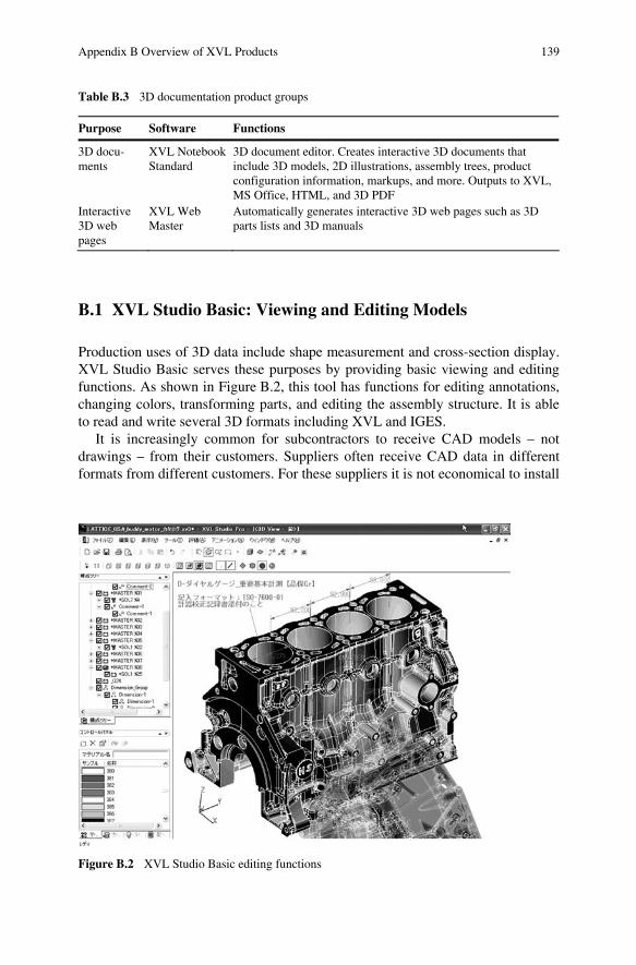
Production uses of 3D data include shape measurement and cross-section display. XVL Studio Basic serves these purposes by providing basic viewing and editing functions. As shown in Figure B.2, this tool has functions for editing annotations, changing colors, transforming parts, and editing the assembly structure. It is able to read and write several 3D formats including XVL and IGES.
It is increasingly common for subcontractors to receive CAD models – not drawings – from their customers. Suppliers often receive CAD data in different formats from different customers. For these suppliers it is not economical to install
Figure B.2 XVL Studio Basic editing functions
140 Appendix B Overview of XVL Products
multiple CAD systems just to view the different CAD models. XVL Studio Basic is the perfect solution for such suppliers.
At large companies, XVL Studio Basic serves as a useful and economical tool for 3D communication, particularly in areas that do not use 3D CAD such as manufacturing plants and production technology departments. Efficient use of XVL Studio Basic eliminates the need for drawings. Traditionally drawings have been used to convey shape, dimensions, and instructions to downstream depart-ments. XVL Studio Basic can display the same information in XVL models.
In this way, XVL eliminates the need for analog processes such as drawings, enabling design information to be digitally sent to downstream processes. Provid-ing such production information to business partners further reinforces collabora-tive business relationships. Such tight partner relationships may become key sources of competitive strength.
B.2 Products for Document Creation Using XVL
XVL is commonly used to create technical documents. There are two basic methods:
1. Attaching 3D models to e-documents and 2. Creating 2D images or illustrations from 3D models, and pasting these into
e-documents
3D models are widely used for parts catalogs and assembly manuals. 3D as-sembly animations, for example, are clear and easy to understand. However, paper technical documents are still widely used. 3D data can streamline the proc-ess of creating paper documents by automatically generating the 2D images and illustrations.
B.2.1 XVL Studio Standard: Creating Animations
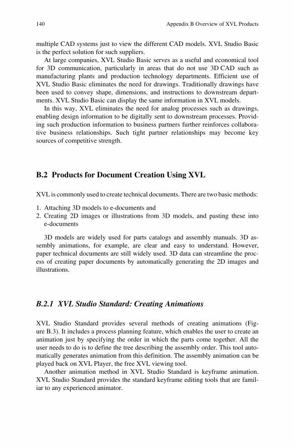
XVL Studio Standard provides several methods of creating animations (Fig-ure B.3). It includes a process planning feature, which enables the user to create an animation just by specifying the order in which the parts come together. All the user needs to do is to define the tree describing the assembly order. This tool auto-matically generates animation from this definition. The assembly animation can be played back on XVL Player, the free XVL viewing tool.
Another animation method in XVL Studio Standard is keyframe animation. XVL Studio Standard provides the standard keyframe editing tools that are famil-iar to any experienced animator.
Appendix B Overview of XVL Products 141
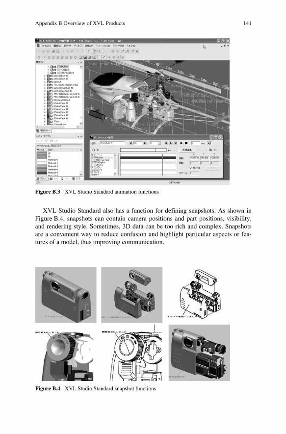
XVL Studio Standard also has a function for defining snapshots. As shown in Figure B.4, snapshots can contain camera positions and part positions, visibility, and rendering style. Sometimes, 3D data can be too rich and complex. Snapshots are a convenient way to reduce confusion and highlight particular aspects or fea-tures of a model, thus improving communication.
Figure B.3 XVL Studio Standard animation functions
Figure B.4 XVL Studio Standard snapshot functions
142 Appendix B Overview of XVL Products
B.2.2 XVL Studio Family: Illustration Functions
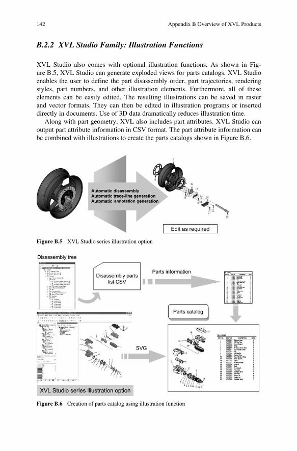
XVL Studio also comes with optional illustration functions. As shown in Fig-ure B.5, XVL Studio can generate exploded views for parts catalogs. XVL Studio enables the user to define the part disassembly order, part trajectories, rendering styles, part numbers, and other illustration elements. Furthermore, all of these elements can be easily edited. The resulting illustrations can be saved in raster and vector formats. They can then be edited in illustration programs or inserted directly in documents. Use of 3D data dramatically reduces illustration time.
Along with part geometry, XVL also includes part attributes. XVL Studio can output part attribute information in CSV format. The part attribute information can be combined with illustrations to create the parts catalogs shown in Figure B.6.
Figure B.5 XVL Studio series illustration option
Figure B.6 Creation of parts catalog using illustration function
Appendix B Overview of XVL Products 143
B.2.3 XVL Notebook: 3D Document Creation
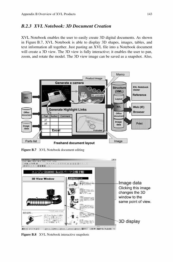
XVL Notebook enables the user to easily create 3D digital documents. As shown in Figure B.7, XVL Notebook is able to display 3D shapes, images, tables, and text information all together. Just pasting an XVL file into a Notebook document will create a 3D view. The 3D view is fully interactive; it enables the user to pan, zoom, and rotate the model. The 3D view image can be saved as a snapshot. Also,
Figure B.7 XVL Notebook document editing
Figure B.8 XVL Notebook interactive snapshots
144 Appendix B Overview of XVL Products
the XVL file has assembly information and part data. This information can be extracted and saved as tables in the document. Furthermore, all these elements, 3D views, 2D snapshots, and table, are linked together. For example, selecting a part in the 3D view can highlight that part’s information in the table. And selecting a 2D snapshot will reorient the 3D view and change the rendering style so that it matches the snapshot (Figure B.8).
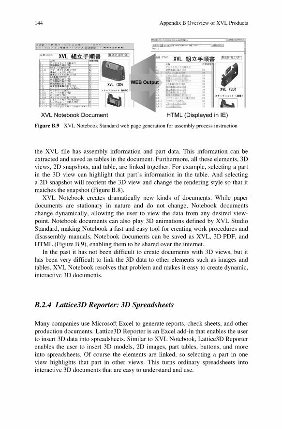
XVL Notebook creates dramatically new kinds of documents. While paper documents are stationary in nature and do not change, Notebook documents change dynamically, allowing the user to view the data from any desired view-point. Notebook documents can also play 3D animations defined by XVL Studio Standard, making Notebook a fast and easy tool for creating work procedures and disassembly manuals. Notebook documents can be saved as XVL, 3D PDF, and HTML (Figure B.9), enabling them to be shared over the internet.
In the past it has not been difficult to create documents with 3D views, but it has been very difficult to link the 3D data to other elements such as images and tables. XVL Notebook resolves that problem and makes it easy to create dynamic, interactive 3D documents.
B.2.4 Lattice3D Reporter: 3D Spreadsheets
Many companies use Microsoft Excel to generate reports, check sheets, and other production documents. Lattice3D Reporter is an Excel add-in that enables the user to insert 3D data into spreadsheets. Similar to XVL Notebook, Lattice3D Reporter enables the user to insert 3D models, 2D images, part tables, buttons, and more into spreadsheets. Of course the elements are linked, so selecting a part in one view highlights that part in other views. This turns ordinary spreadsheets into interactive 3D documents that are easy to understand and use.
Figure B.9 XVL Notebook Standard web page generation for assembly process instruction
Appendix B Overview of XVL Products 145
B.2.5 XVL Web Master: Automatic Webpage Generation
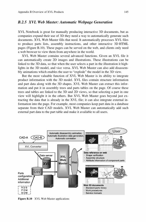
XVL Notebook is great for manually producing interactive 3D documents, but as companies expand their use of 3D they need a way to automatically generate such documents. XVL Web Master fills that need. It automatically processes XVL files to produce parts lists, assembly instructions, and other interactive 3D HTML pages (Figure B.10). These pages can be served on the web, and clients only need a web browser to view them from anywhere in the world.
XVL Web Master contains several advanced functions. Given an XVL file it can automatically create 2D images and illustrations. These illustrations can be linked to the 3D data, so that when the user selects a part in the illustration it high-lights in the 3D model, and vice versa. XVL Web Master can also add disassem-bly animations which enables the user to “explode” the model in the 3D view.
But the most valuable function of XVL Web Master is its ability to integrate product information with the 3D model. XVL files contain structure information and part data along with the 3D shapes. XVL Web Master can extract this infor-mation and put it in assembly trees and parts tables on the page. Of course these trees and tables are linked to the 3D and 2D views, so that selecting a part in one view will highlight it in the others. But XVL Web Master goes beyond just ex-tracting the data that is already in the XVL file; it can also integrate external in-formation into the page. For example, most companies keep part data in a database separate from their CAD models. XVL Web Master can automatically add such external part data to the part table and make it available to all users.
Figure B.10 XVL Web Master applications
146 Appendix B Overview of XVL Products
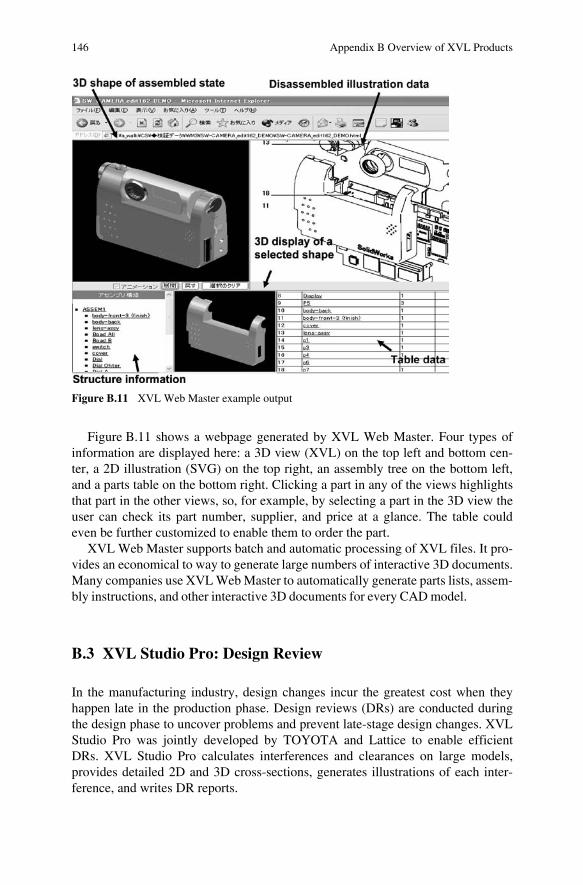
Figure B.11 shows a webpage generated by XVL Web Master. Four types of information are displayed here: a 3D view (XVL) on the top left and bottom cen-ter, a 2D illustration (SVG) on the top right, an assembly tree on the bottom left, and a parts table on the bottom right. Clicking a part in any of the views highlights that part in the other views, so, for example, by selecting a part in the 3D view the user can check its part number, supplier, and price at a glance. The table could even be further customized to enable them to order the part.
XVL Web Master supports batch and automatic processing of XVL files. It pro-vides an economical to way to generate large numbers of interactive 3D documents. Many companies use XVL Web Master to automatically generate parts lists, assem-bly instructions, and other interactive 3D documents for every CAD model.
B.3 XVL Studio Pro: Design Review
In the manufacturing industry, design changes incur the greatest cost when they happen late in the production phase. Design reviews (DRs) are conducted during the design phase to uncover problems and prevent late-stage design changes. XVL Studio Pro was jointly developed by TOYOTA and Lattice to enable efficient DRs. XVL Studio Pro calculates interferences and clearances on large models, provides detailed 2D and 3D cross-sections, generates illustrations of each inter-ference, and writes DR reports.
Figure B.11 XVL Web Master example output
Appendix B Overview of XVL Products 147
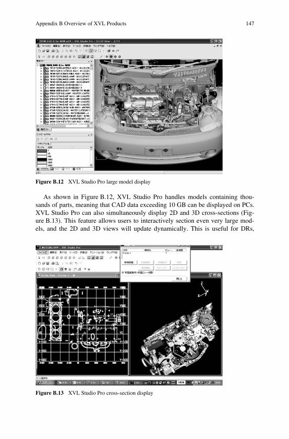
As shown in Figure B.12, XVL Studio Pro handles models containing thou-sands of parts, meaning that CAD data exceeding 10 GB can be displayed on PCs. XVL Studio Pro can also simultaneously display 2D and 3D cross-sections (Fig-ure B.13). This feature allows users to interactively section even very large mod-els, and the 2D and 3D views will update dynamically. This is useful for DRs,
Figure B.13 XVL Studio Pro cross-section display
Figure B.12 XVL Studio Pro large model display
148 Appendix B Overview of XVL Products
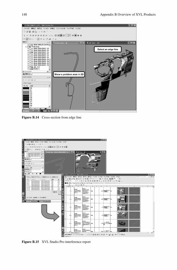
Figure B.14 Cross-section from edge line
Figure B.15 XVL Studio Pro interference report
Appendix B Overview of XVL Products 149
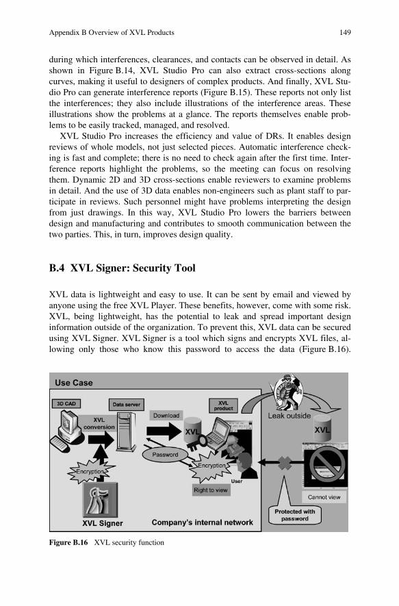
during which interferences, clearances, and contacts can be observed in detail. As shown in Figure B.14, XVL Studio Pro can also extract cross-sections along curves, making it useful to designers of complex products. And finally, XVL Stu-dio Pro can generate interference reports (Figure B.15). These reports not only list the interferences; they also include illustrations of the interference areas. These illustrations show the problems at a glance. The reports themselves enable prob-lems to be easily tracked, managed, and resolved.
XVL Studio Pro increases the efficiency and value of DRs. It enables design reviews of whole models, not just selected pieces. Automatic interference check-ing is fast and complete; there is no need to check again after the first time. Inter-ference reports highlight the problems, so the meeting can focus on resolving them. Dynamic 2D and 3D cross-sections enable reviewers to examine problems in detail. And the use of 3D data enables non-engineers such as plant staff to par-ticipate in reviews. Such personnel might have problems interpreting the design from just drawings. In this way, XVL Studio Pro lowers the barriers between design and manufacturing and contributes to smooth communication between the two parties. This, in turn, improves design quality.
B.4 XVL Signer: Security Tool
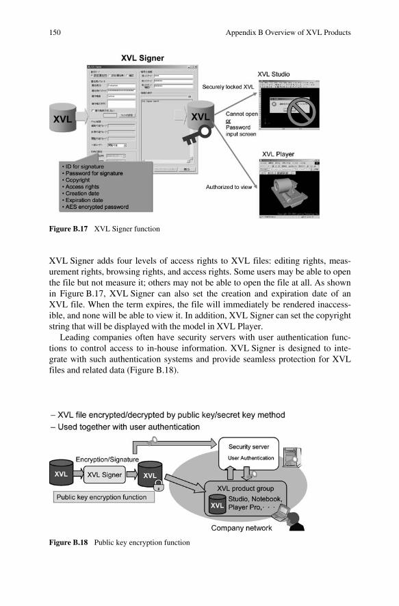
XVL data is lightweight and easy to use. It can be sent by email and viewed by anyone using the free XVL Player. These benefits, however, come with some risk. XVL, being lightweight, has the potential to leak and spread important design information outside of the organization. To prevent this, XVL data can be secured using XVL Signer. XVL Signer is a tool which signs and encrypts XVL files, al-lowing only those who know this password to access the data (Figure B.16).
Figure B.16 XVL security function
150 Appendix B Overview of XVL Products
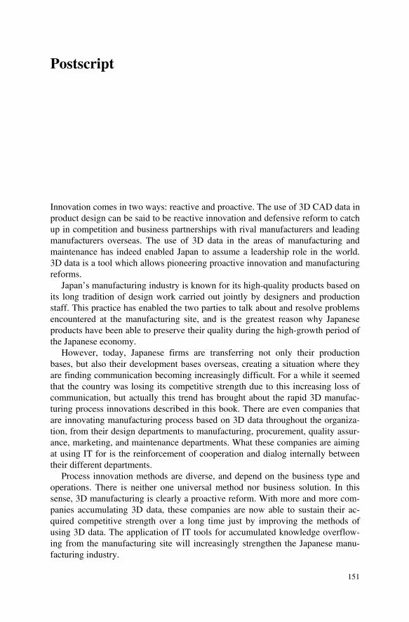
XVL Signer adds four levels of access rights to XVL files: editing rights, meas-urement rights, browsing rights, and access rights. Some users may be able to open the file but not measure it; others may not be able to open the file at all. As shown in Figure B.17, XVL Signer can also set the creation and expiration date of an XVL file. When the term expires, the file will immediately be rendered inaccess-ible, and none will be able to view it. In addition, XVL Signer can set the copyright string that will be displayed with the model in XVL Player.
Leading companies often have security servers with user authentication func-tions to control access to in-house information. XVL Signer is designed to inte-grate with such authentication systems and provide seamless protection for XVL files and related data (Figure B.18).
Figure B.17 XVL Signer function
Figure B.18 Public key encryption function
151
Postscript
Innovation comes in two ways: reactive and proactive. The use of 3D CAD data in product design can be said to be reactive innovation and defensive reform to catch up in competition and business partnerships with rival manufacturers and leading manufacturers overseas. The use of 3D data in the areas of manufacturing and maintenance has indeed enabled Japan to assume a leadership role in the world. 3D data is a tool which allows pioneering proactive innovation and manufacturing reforms.
Japan’s manufacturing industry is known for its high-quality products based on its long tradition of design work carried out jointly by designers and production staff. This practice has enabled the two parties to talk about and resolve problems encountered at the manufacturing site, and is the greatest reason why Japanese products have been able to preserve their quality during the high-growth period of the Japanese economy.
However, today, Japanese firms are transferring not only their production bases, but also their development bases overseas, creating a situation where they are finding communication becoming increasingly difficult. For a while it seemed that the country was losing its competitive strength due to this increasing loss of communication, but actually this trend has brought about the rapid 3D manufac-turing process innovations described in this book. There are even companies that are innovating manufacturing process based on 3D data throughout the organiza-tion, from their design departments to manufacturing, procurement, quality assur-ance, marketing, and maintenance departments. What these companies are aiming at using IT for is the reinforcement of cooperation and dialog internally between their different departments.
Process innovation methods are diverse, and depend on the business type and operations. There is neither one universal method nor business solution. In this sense, 3D manufacturing is clearly a proactive reform. With more and more com-panies accumulating 3D data, these companies are now able to sustain their ac-quired competitive strength over a long time just by improving the methods of using 3D data. The application of IT tools for accumulated knowledge overflow-ing from the manufacturing site will increasingly strengthen the Japanese manu-facturing industry.

152 Postscript
The twenty-first century is said to be an era for those in control of knowledge and information. In rapidly changing times, the speed at which knowledge be-comes obsolete will accelerate even more. This will be accompanied by the need to accumulate knowledge in the company, convey it, and share it even more quickly. Needless to say, intellectual labor cannot be improved just by pep talks. Rules for supporting sound stable intellectual labor are required, the most reliable of which is the framework for using 3D data. Today, as manufacturers arm themselves with IT as a tool to win in the global competition, it is hoped that this book will contribute in some way by providing beneficial information.
Index
2
2D drawing interchange file (DXF) 63
3
32-bit machine 134 32-bit PC 9 3D data vi 3D data information distribution platform
25 3D document 145
3D catalog 111 3D digital document 143 3D instruction manual 124 3D interactive manual 124 3D manual 42 3D parts list 38 3D visual manual 43 interactive 3D document 144 technical 3D document 111
3D drawing 120, 123 3D Everywhere 13, 130 3D manufacturing 151 3D PDF 8, 133, 138 3D viewer 79, 83, 91 3D XML 7
6
64-bit PC 9, 134
A
ALPINE PRECISION 34, 81 animation 140
3D process animation 34, 110 assembly instruction 69, 120
assembly procedure 110 automating the translation and flow of
information 78
B
Bill Of Materials (BOM) 28 broadband internet 2
C
CAD 27 3D CAD vi, 2 CATIA 7, 117 Pro/ENGINEER 99 SolidWorks 110 Unigraphic 71
CAE 124 CASIO 34, 99 CAT 124 clearance check 37 collaborative manufacturing 34 combination manufacturing 34 comma separated value (CSV) 38 communication pipeline 63 complete digitalization 69 computer-aided engineering (CAE) 46 computer-aided testing (CAT) 48 contour map 47 core of design 57 CRIC cycle ix cross-section 36, 53
D
data transfer time 100 design and manufacturing process
innovation 60
153
154 Index
design information v, 4, 23 design intent 57, 72, 83, 110 design quality 58 design review (DR) vii, 33, 34, 51, 60, 84,
97, 122, 146 online design review (ODR) 107
documentation 14 downstream 13 downstream process 63 drawing 15 drawing-less vi, 85, 88, 96 DWF 8
E
ECMA 8 eDrawing 110 electric discharge machining (EDM) 92 eliminating drawing and report 123 e-manual 101 Engineering Change Order (ECO) 112 ERP system 114
F
file management system 125 frontload 101
front-loading 67
H
HTML (Hyper Text Markup Language) 12
I
IGES 27, 139 illustration 142 Information Technology (IT) 1 instruction manual 34, 102 interference 36, 53 interference checking 58 interference problem 36 interference report 149
J
Japan Automobile Manufacturers’ Association (JAMA) 123
JT 8
K
Koutei 75 KVAL 34, 109
L
L-3 COMMUNICATIONS (L-3C) 34, 109
lattice technology vi, ix lightweight 3D 10 lightweight 3D data vi, 11, 131 liquid crystal display (LCD) 59
M
MAN 34 MAN Nutzfahrzeuge AG 115 manufacturing information 17 master data 17 Microsoft Excel 144 MONOZUKURI v, 7
N
NC programming 93 NIKON 33, 59
O
official data 17 original drawing data 27 owner manual 101
P
paperless communication 84 parts catalog 34 PDF 27 PDM 125 polygon 8 process management system 73, 74 product assembly 34 product data management (PDM) 3 product data quality (PDQ) 4 product development cycle 99 product lifecycle 91 product lifecycle management (PLM) vii product maintenance 34 production instruction 69 prototype review 28
Q
quality assurance 120
R
report 34, 82, 144 report-less 88 ROI 115
Index 155
S
security 67, 89, 97, 126, 150 semiconductor 59 service manual 101 sheet metal DR 55 simultaneous engineering 51 Single Source Multi Use 99 snapshot 141 SONY 21 SVG (Scalable Vector Graphics) 133
T
technical document 123 technical documentation 119 technological barrier 110 TOKAI RIKA 34, 91 total cost of ownership (TCO) 22 TOYOTA 33 TOYOTA MOTOR CORPORATION
(TOYOTA) 51
U
U3D 8
V
very large data 14 viewer 12
VRML 8 VRML97 (Virtual Reality Modeling
Language) 129
X
XML (eXtensible Markup Language) 12, 130, 133
XVL vi, ix, 9, 27, 129 P-XVL (Precise XVL) 132 V-XVL 67 V-XVL (Visual XVL) 134 XV2 67 XVL Kernel 133 XVL-based communication system
87 XVL product 137
Lattice3D Reporter 144 XVL Notebook 71, 93, 143 XVL Player 115, 132, 137 XVL Signer 149 XVL Studio 85, 101, 137 XVL Studio Basic 139 XVL Studio Pro 52, 146 XVL Studio Standard 140 XVL Web Master 67, 71, 85, 97,
112, 145
Y
YAMAGATA CASIO 34, 69