Appendix A Best Management Practice Toolbox€¦ · Appendix A – Best Management Practice Toolbox...
78
Appendix A Best Management Practice Toolbox
Transcript of Appendix A Best Management Practice Toolbox€¦ · Appendix A – Best Management Practice Toolbox...

Appendix A
Best Management Practice Toolbox

Appendix A – Best Management Practice Toolbox
A-1
BEST MANAGEMENT PRACTICE TOOLBOX
A BMP is simply a tool, and a tool can be used appropriately and inappropriately. A good analogy would be the use of a hammer to install a screw. Although it may ultimately work, the hammer is not the best tool for the job. Similarly, use of the wrong BMP for a particular application might ultimately work, however, the task will not be done as effectively as it would be with the right tool or BMP. Information about BMP selection and implementation, as well as maintenance (if applicable), is provided in this BMP Toolbox. Alternate individual engineering solutions will be reviewed and considered.
Acronyms used in this appendix: ADEC.............................................................. Alaska Department of Environmental Conservation ADOT&PF............................................ Alaska Department of Transportation and Public Facilities AWWU............................................................................Anchorage Water and Wastewater Utility BMP..................................................................................................... Best Management Practice cfs ...............................................................................................................Cubic Feet per Second CGP................................................................................................... Construction General Permit DCM ...........................................................................................................Design Criteria Manual EPA ........................................................................................... Environmental Protection Agency ESC .................................................................................................Erosion and Sediment Control LID..........................................................................................................Low Impact Development MOA ...................................................................................................... Municipality of Anchorage MS4 ............................................................................... Municipal Separate Storm Sewer System NOI ......................................................................................................................... Notice of Intent NOT.............................................................................................................. Notice of Termination NPDES ...............................................................National Pollutant Discharge Elimination System OGS............................................................................................................. Oil and Grit Separator SPCC.......................................................... Spill Prevention, Control, and Countermeasure Plans SWPPP.............................................................................. Storm Water Pollution Prevention Plan SWTP ................................................................................................Storm Water Treatment Plan SWTPRGM.............................................. Storm Water Treatment Plan Review Guidance Manual WMS......................................................................................... Watershed Management Services

Appendix A – Best Management Practice Toolbox
A-2
Table A1 Matrix of Best Management Practices SC – Source Control RT – Runoff Treatment FA – Flow Attenuation
Temporary Controls Permanent Controls Required
Page in Appendix
Fact Sheet Provided? Best Management Practice
Erosion and Sediment Control
Waste, pollutant
management Infiltration
Flow control and Detention
Biofiltration Procedural
or Maintenance
Consideration for All Sites
EROSION CONTROL A-5 Yes Scheduling to Minimize Soil Exposure SC A-6 Yes Phased clearing and grading SC A-7 Yes Flagging and fencing of clearing limits SC A-8 Yes Benching SC A-9 Yes Slopes requiring cut and fill design SC
A-10 Yes Effects of erosion control on adjacent property SC A-11 Yes Surface roughening SC A-12 Yes Plastic covering SC A-13 Yes Mulching SC A-14 Yes Erosion control blankets SC A-15 Yes Seeding SC SC
No Sodding SC SC A-16 Yes Slope revegetation SC SC
TEMPORARY SEDIMENTATION CONTROL A-17 Yes Silt fence RT A-19 Yes Sandbag filter RT A-20 Yes Catchbasin insert RT A-21 Yes Catchbasin covering RT A-22 Yes Block and gravel barrier RT A-24 Yes Catchbasin silt fence RT A-26 Yes Curb inlet protection RT A-28 Yes Wattles RT
FLOW CONTROL AND ENERGY DISSIPATION A-30 Yes Interceptor ditch SC A-31 Yes Temporary diversion dike SC A-32 Yes Down drain SC A-22 Yes Gravel check dam RT A-35 Yes Storm drain diffuser RT RT A-36 Yes Outlet protection RT RT A-59 Yes Rock swale SC SC
CONSTRUCTION ACTIVITIES CONTROLS No Inspection and maintenance SC No Stockpile maintenance
A-38 Yes Stockpile organic soils for revegetation SC SC A-39 Yes Concrete washout SC A-40 Yes Dewatering Controls RT A-48 Yes Dust control SC A-49 Yes Sweeping SC SC A-50 Yes Gravel construction exit SC
A-51 Yes Truck wheel wash basin SC
A-52 Yes Mud mats SC

Appendix A – Best Management Practice Toolbox
A-3
Table A1 Matrix of Best Management Practices (continued) SC – Source Control RT – Runoff Treatment FA – Flow Attenuation
Temporary Controls Permanent Controls Required
Page in Appendix
Fact Sheet Provided? Best Management Practice
Erosion and Sediment Control
Waste, pollutant
management Infiltration
Flow Control
and Detention
Biofiltration Procedural
and/or Maintenance
Consideration for All Sites
PERMANENT PHYSICAL CONTROLS A-60 Yes Outfall protections RT RT, FA A-53 Yes Sedimentation basin (wet pond) RT RT, FA
No Infiltration basin RT, FA
No Infiltration trench (see the MOA LID Design Guidance Manual) RT, FA
No Presettling basin RT No Extended detention dry pond RT, FA
A-55 Yes Proprietary oil and grit separators RT A-57 Yes Vegetated filter strip RT A-58 Yes Bioswale (Grassed swale) RT A-62 Yes Constructed wetlands RT, FA A-61 Yes Use of existing wetlands RT, FA
No Riparian improvements RT No Restore native plant species RT DESIGN PHASE and OTHER LID CONTROLS
A-63 Yes Preservation of natural drainage systems SC A-64 Yes Preservation of natural vegetation SC, FA SC, FA SC, FA A-66 Yes LID: reinforced turf driveways SC A-65 Yes LID: reduced lot grading SC
A-67 Yes LID: rain garden (see the MOA LID Design Guidance Manual) SC, FA SC, FA
A-68 Yes Minimize disturbance/maintenance via cluster development SC 56 No LID: minimize impervious areas SC 57 No Reduce hydraulic connectivity of impervious surfaces SC, FA SOURCE CONTROLS FOR URBAN LAND USE ACTIVITIES (see Appendix
D)
A-69 Yes Parking lot management SC A-70 Yes Snow storage facility operations SC A-72 Yes Liquid Storage SC A-71 Yes Vehicle and equipment washing SC A-73 Yes Materials storage SC
No Fuel and vehicle maintenance staging areas SC No Spill prevention and control plan SC No Maintenance of urban runoff facilities SC No Roof runoff management FA SC No Herbicide, pesticide, and fertilizer application SC SC No Petroleum product handling SC SC No Solid waste disposal SC SC

Appendix A – Best Management Practice Toolbox
A-4
Erosion and Sediment Control Practice Symbols The use of symbols for different ESC BMPs is helpful in site plans for SWPPP submissions. The symbols are a basic shorthand for the plan preparation. The symbols shown in Figure 1A are an example; any symbols are acceptable as long as a key identifying them is provided.
PRESERVING NATURAL VEGETATION
BUFFER ZONE
PLASTINC COVERING
STABILIZATION MATTING
MULCHING
SEEDING, TEMPORARY
SEEING, FINAL
CHECK DAM
OUTLET PROTECTION
STRAW BALE BARRIER
TEMPORARY BERM
INTERCEPTOR DITCH OR BERM
TEMPORARY DIVERSIONS
PIPE SLOPE DRAINS
DUST CONTROL
STABLIZED CONSTRUCTION EXIT
SILT FENCE
STORM DRAIN INLET PROTECTION
SEDIMENT TRAP
Figure 1A: ESC Practice Symbols
Appendix A – Best Management Practice Toolbox
A-5
Scheduling to Minimize Soil Exposure
The short construction season in Anchorage does not always allow flexibility for mass earthwork on each project to be performed at the ideal time of year. Because nothing is more unpredictable than the weather, contingencies must be developed to cover variations in climatic conditions. However, certain weather trends do exist in Anchorage and must be addressed in the project schedule. Care must be taken to minimize weather impacts. Although it may be advantageous to an owner or contractor to work in early spring or late fall, the downside must be understood – ESCs will require more attention and maintenance during these periods. Scheduling is a temporary BMP.
Selection
Any project can benefit from a well-conceived schedule that takes into account seasonal ESC issues.
Implementation
Discussions with the owner or contractor can aid in understanding the construction process in Anchorage and how to take advantage of dry periods to reduce erosion and sediment concerns.

Appendix A – Best Management Practice Toolbox
A-6
Phased Clearing and Grading
Phased clearing and grading can significantly reduce the amount of disturbed area on a construction site. By phasing the construction, the time that soils are left exposed and the total area that is exposed during the rainy season can be reduced. Phasing the clearing and grading operations is a temporary BMP.
Selection
• Any project can benefit from a schedule that phases the construction to account for ESC issues.
• Discussions with the owner or contractor can aid in understanding the critical construction timelines in Anchorage and how to phase the land clearing construction activities to coincide with periods of expected dry weather.
Implementation
• Show areas to be cleared and graded in phases clearly on the site plan.
• Clear and grade as necessary for immediate construction only.
Maintenance
• Apply erosion control practices to cleared areas.
• Comply with CGP temporary stabilization requirements if the cleared area will not be worked immediately.

Appendix A – Best Management Practice Toolbox
A-7
Flagging and Fencing of Clearing Limits
Flagging and fencing of clearing limits is the most positive method to ensure that the area of disturbance is controlled. As construction progresses and excavation and stockpiles occur at the site, it is easy to inadvertently expand the area of disturbance into areas to be protected without the presence of visual cues or physical barriers. Delineation of clearing limits is a temporary BMP. Figure 2A illustrates the flagging and fencing clearing limits BMP.
Selection
Flagging and fencing of clearing limits is applicable for all construction sites.
Implementation
• Designate areas of retained vegetation clearly on the plans. Required buffers should also be designated on the site design plan.
• Delineate the clearing limits with a continuous length of brightly colored tape. Support highly visible tape with vegetation or stakes, 3 to 6 feet high.
• Individual trees and shrubs that are to be preserved within the cleared area should be identified.
• If the area is to be flagged only, the flagging should be spaced no greater than 200 feet apart and closer in wooded or hilly areas.
Maintenance
• Immediately repair or replace damaged fencing or flagging necessary to ensure the area of disturbance does not enlarge should be repaired or replaced.
• Check that vandals have not moved stakes or flagging.
• Make sure that the construction is staying within the clearing limits.
Figure 2A: Flagging and Fencing of Clearing Limits

Appendix A – Best Management Practice Toolbox
A-8
Benching
Benching reduces erosion damage by segmenting the effective slope length, thus intercepting surface runoff and conveying the discharge along the benches at a slower velocity. Figure 6A shows a benching diagram.
Selection
Benches should not be used in sandy areas or on soils that are too rocky for construction and maintenance. Benching should only be used where the concentrated flows from the benches can be discharged without erosion of downstream areas.
Implementation
The plans and specifications for the bench construction should be followed. Benches must be constructed along contours in order to minimize the velocity of intercepted runoff.
Maintenance
Maintenance should be performed as needed. Benches should be inspected regularly; at least once a year and after large storm events.
• Check for and correct erosion of the benches.
• Check for and remove trash collecting in the benches.
• Look for and correct erosion at the bench discharge points.
Figure 6A: Benching

Appendix A – Best Management Practice Toolbox
A-9
Slopes Requiring Cut and Fill Design
Cut and fill slopes should be constructed in a manner that will minimize erosion by taking into consideration the length and steepness of slopes, soil types, upslope drainage areas, and groundwater conditions.
Selection
For use on all cut or fill slopes higher than 3 feet.
Implementation
Design cut and fill slopes to be at stable angles, or less than the normal angle of repose, to minimize erosion and slope failure potential.
Maintenance
Slopes should not be left at angles steeper than their final design any longer than necessary for other site activities.

Appendix A – Best Management Practice Toolbox
A-10
Effects of Erosion Control Measures on Adjacent Properties
Plan and design all streambank, shoreline, and navigation structures so that they do not transfer erosion energy or otherwise cause visible loss of surrounding streambanks and shorelines. Many streambank or shoreline protection projects result in a transfer of energy from one area to another, which causes increased erosion in the adjacent area. Property owners should consider the possible effects of erosion control measures on other properties located along the shore.
Appendix A – Best Management Practice Toolbox
A-11
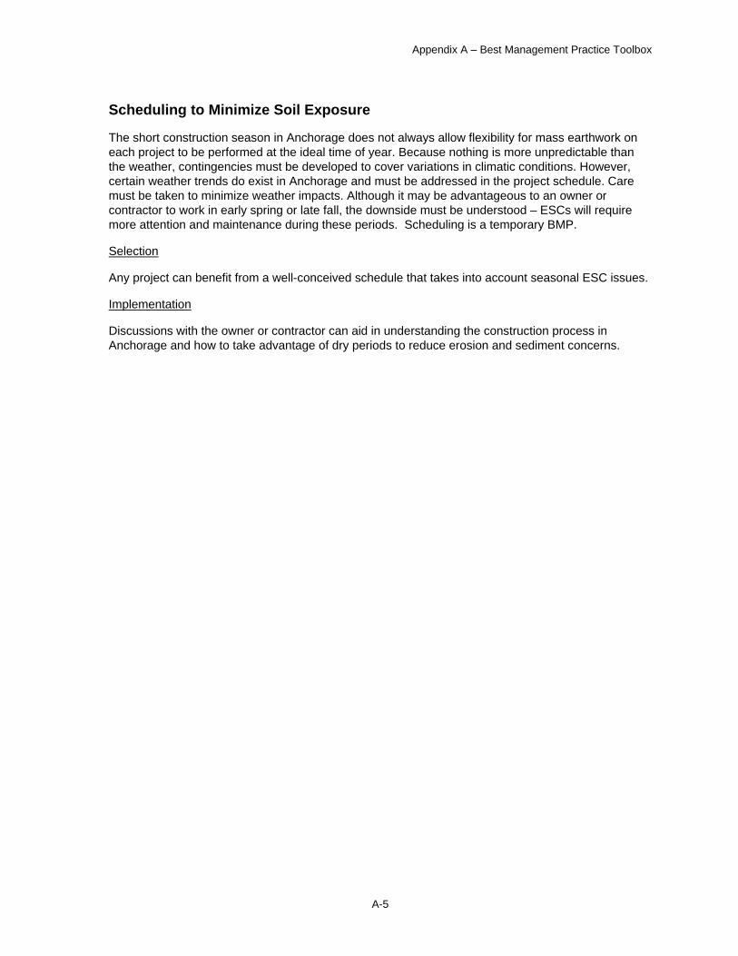
Surface Roughening
Surface roughening, also called cat-tracking, is used on slopes to provide small pockets for trapping runoff and allowing infiltration. This temporary BMP is shown in Figure 5A. Surface roughening aids in the establishment of vegetation cover by providing a rough soil surface with horizontal depressions.
Selection
Surface roughening works on most sloped areas, except hard pan.
Implementation
• The contractor should run tracked machinery along the fall line of the slope with the blade raised.
• Roughening with tracked machinery needs to be limited to avoid compaction of the soil surface.
• Tracking should be performed in a manner that covers the slope with no more than one foot between tracks.
• Roughened areas should be seeded and mulched immediately.
Maintenance
Surface roughening is a temporary measure and should be inspected and shaped after each rainfall that causes erosion or after no more than 90 days since the last shaping, to minimize erosion.
• Make sure the area is adequately covered with tracking.
• Check for erosion after significant rainstorms. If rills appear, regrade and roughen again and reseed eroded area immediately, as appropriate.
Figure 5A: Surface Roughening
Appendix A – Best Management Practice Toolbox
A-12
Plastic Covering
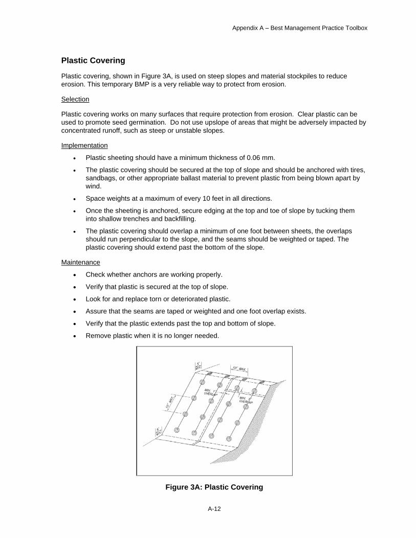
Plastic covering, shown in Figure 3A, is used on steep slopes and material stockpiles to reduce erosion. This temporary BMP is a very reliable way to protect from erosion.
Selection
Plastic covering works on many surfaces that require protection from erosion. Clear plastic can be used to promote seed germination. Do not use upslope of areas that might be adversely impacted by concentrated runoff, such as steep or unstable slopes.
Implementation
• Plastic sheeting should have a minimum thickness of 0.06 mm.
• The plastic covering should be secured at the top of slope and should be anchored with tires, sandbags, or other appropriate ballast material to prevent plastic from being blown apart by wind.
• Space weights at a maximum of every 10 feet in all directions.
• Once the sheeting is anchored, secure edging at the top and toe of slope by tucking them into shallow trenches and backfilling.
• The plastic covering should overlap a minimum of one foot between sheets, the overlaps should run perpendicular to the slope, and the seams should be weighted or taped. The plastic covering should extend past the bottom of the slope.
Maintenance
• Check whether anchors are working properly.
• Verify that plastic is secured at the top of slope.
• Look for and replace torn or deteriorated plastic.
• Assure that the seams are taped or weighted and one foot overlap exists.
• Verify that the plastic extends past the top and bottom of slope.
• Remove plastic when it is no longer needed.
Figure 3A: Plastic Covering
Appendix A – Best Management Practice Toolbox
A-13
Mulching Mulching is the application of plant materials such as straw or other materials to the soil surface. Surface mulch is an effective and cost-effective means of controlling runoff and erosion on disturbed areas prior to revegetation. Mulch absorbs the raindrop impact energy and minimizes soil detachment, which is the first step of erosion. Mulching is a temporary BMP that helps seedlings germinate and grow by conserving moisture and can be used in unseeded areas to protect against erosion during winter or until final grading and stabilization can be accomplished. Mulches should be free of weeds and unwanted seeds to prevent invasive plants.
Selection
Mulch can be used successfully on the majority of construction projects in Anchorage. Mulch design life is six months or less. Appropriate for use on slopes of 3:1 or flatter.
Implementation
Mulch is most commonly used in conjunction with seeding. Mulch should be uniformly spread by hand or blower to provide 75 percent ground cover. When straw mulch may be exposed to wind, it must be anchored immediately after spreading. Mulch should be applied immediately after seeding to improve seed germination. Depth of the applied mulch should be not less than one inch and not more than 2 inches.
Maintenance
After mulch has been applied and anchored properly, little additional maintenance is required during the first few months. After high winds or significant rainstorms, mulch-covered areas should be checked for adequate cover and remulched if necessary. To be effective, mulch must last until vegetation develops to provide an erosion-resistant cover.
• Confirm mulch is adequately watered. • Check to ensure erosion is not occurring. • Watch for and repair washout of mulch. • Mulching may degrade slowly in Anchorage’s climate; therefore, some mulches may need to
be removed once vegetation is established.
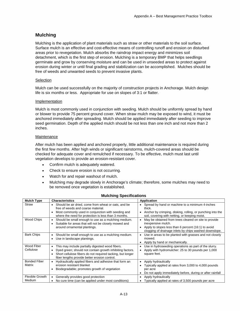
Mulching Specifications Mulch Type Characteristics Application Straw • Should be air dried, come from wheat or oats, and be
free of weeds and coarse material. • Most commonly used in conjunction with seeding and
where the need for protection is less than 3 months.
• Spread by hand or machine to a minimum 4-inches thick.
• Anchor by crimping, disking, rolling, or punching into the soil, covering with netting, or keeping moist.
Wood Chips • Should be small enough to use as a mulching medium. • Suitable for areas that will not be closely mowed and
around ornamental plantings.
• May be obtained from trees cleared on site to provide inexpensive mulch.
• Apply to slopes less than 6 percent (16:1) to avoid clogging of drainage inlets by chips washed downslope.
Bark Chips • Should be small enough to use as a mulching medium. • Use in landscape plantings.
• Use in areas to be planted with grasses and not closely mowed.
• Apply by hand or mechanically. Wood Fiber Cellulose
• This may include partially digested wood fibers. • Dyed green; should not contain growth inhibiting factors. • Short cellulose fibers do not required tacking, but longer
fiber lengths provide better erosion control.
• Use in hydroseeding operations as part of the slurry. • Apply with hydromulcher: 25 to 30 pounds per 1,000
square feet.
Bonded Fiber Matrix
• Hydraulically applied fibers and adhesive that form an erosion resistant blanket
• Biodegradable; promotes growth of vegetation
• Apply hydraulically • Typically applied at rates from 3,000 to 4,000 pounds
per acre • Do not apply immediately before, during or after rainfall
Flexible Growth Medium
• Generally provides good protection • No cure time (can be applied under most conditions)
• Apply hydraulically • Typically applied at rates of 3,500 pounds per acre

Appendix A – Best Management Practice Toolbox
A-14
Erosion Control Blankets
Erosion control blankets are used as an alternative to mulch but can also be used to provide structural erosion protection. They aid in controlling erosion on areas by providing a temporary or semi-permanent protective cover made of straw, jute, wood, plant fibers, or artificial products. Figure 4A depicts the use of erosion control blankets.
Selection
Erosion control blankets function best in providing a protective cover on slopes and channels where the erosion hazard is high and plant growth is likely to be slow; generally on slopes steeper than 3H:1V and greater than 10 feet of vertical relief.
Implementation • The manufacturer’s recommendations for installation should be followed. • Blankets must be anchored; spacing depends on type of material and slope steepness, • Maintain a firm continuous contact between the blanket and soil to prevent erosion below the
blanket.
Maintenance
When erosion blankets have been installed and anchored properly, little additional maintenance is required during the first few months. After high winds or significant rainstorms have occurred, blanketed areas should be checked for adequate cover and repaired if necessary. The blanket must last until vegetation develops to provide an erosion-resistant cover. After any damaged slope or drainage course has been repaired, the material should be reinstalled.
• Check that surfaces adhere, fasteners remain secure, and covering is in tight contact with soil surface beneath.
• After significant rainstorms, check for erosion and undermining and repair promptly.
• Look for and repair washouts.
Figure 4A: Erosion Control Blankets
Appendix A – Best Management Practice Toolbox
A-15
Seeding
Seeding is the establishment of perennial vegetation, usually lawns, on disturbed areas from seed. Seeding can be a temporary or permanent measure.
The seed mixture should be free of weeds and unwanted seeds to prevent invasive plants.
Selection
This practice is used when vegetation is desired for temporary or final stabilization. Temporary seeding is not recommended if permanent seeding will be completed in the same growing season. Other temporary stabilization should be considered.
Implementation
Proper seedbed preparation and the use of high quality seed are essential to the success of this practice. • Seeding shall take place as soon as practicable after the last ground-disturbing activities in an
area, but not during the period August 15 through May 1 unless dormant seeding is used. • Supplement topsoil as necessary to ensure a minimum of 4 inches of topsoil in areas to be
permanently seeded. Work topsoil into the layer below for a depth of at least 6 inches. • The project plans and specifications produced by the landscape architect or engineer shall be
followed.
Maintenance
All seeding should be inspected periodically following installation. Seeded areas should be checked for erosion and flooding after significant rainstorms. Any repairs must be made immediately.
• Water seeded areas daily until initial ground cover is established if rainfall does not provide moisture for seed germination.
• Check the area to ensure the grass is growing; replant at appropriate times if required. • Look for damage to the seeded area due to runoff and repair before the next runoff event. • Check for erosion and flooding after significant rainstorms and repair before the next runoff
event.
Appendix A – Best Management Practice Toolbox
A-16
Slope Revegetation
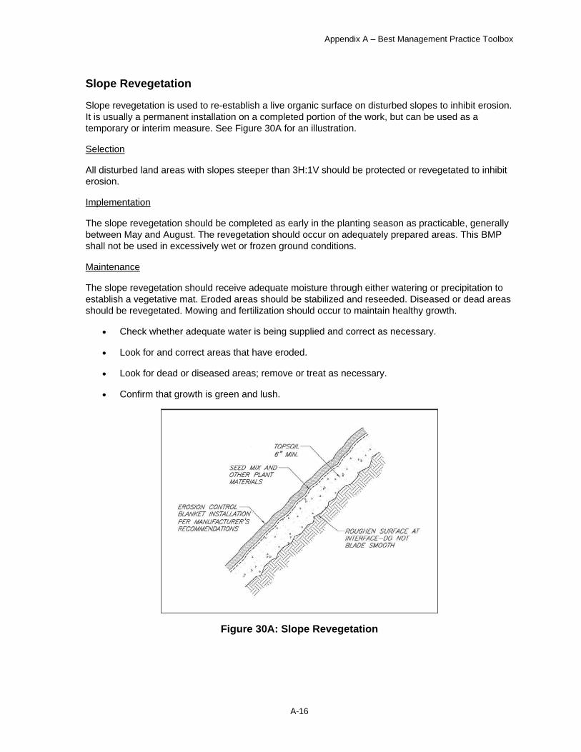
Slope revegetation is used to re-establish a live organic surface on disturbed slopes to inhibit erosion. It is usually a permanent installation on a completed portion of the work, but can be used as a temporary or interim measure. See Figure 30A for an illustration.
Selection
All disturbed land areas with slopes steeper than 3H:1V should be protected or revegetated to inhibit erosion.
Implementation
The slope revegetation should be completed as early in the planting season as practicable, generally between May and August. The revegetation should occur on adequately prepared areas. This BMP shall not be used in excessively wet or frozen ground conditions.
Maintenance
The slope revegetation should receive adequate moisture through either watering or precipitation to establish a vegetative mat. Eroded areas should be stabilized and reseeded. Diseased or dead areas should be revegetated. Mowing and fertilization should occur to maintain healthy growth.
• Check whether adequate water is being supplied and correct as necessary.
• Look for and correct areas that have eroded.
• Look for dead or diseased areas; remove or treat as necessary.
• Confirm that growth is green and lush.
Figure 30A: Slope Revegetation
Appendix A – Best Management Practice Toolbox
A-17
Silt Fence
Silt fences are used to filter sediments from sheet flow runoff on sloped areas. The fences can be very effective in removing sediment from runoff. See Figure 15A for details on this temporary BMP.
Selection
Silt fences are appropriate for the majority of construction sites. The design life a silt fence is six months or less. The maximum contributory sheet flow drainage area shall not exceed 0.25 acres per 100 feet of silt fence. Use of a silt fence is usually more complex, expensive, and maintenance-prone than other slope stabilization measures.
Implementation
Silt fences should be installed at right angles to the slope and along contours. Posts should be securely installed. The filter fabric should be securely attached to the posts. The filter fabric should be keyed into the surrounding earth.
Maintenance
The filter fabric should be kept up to maintain its function. It should be replaced if it is torn or frayed. The posts should be reinstalled if loose. The filter fabric should be reinstalled if it is not keyed into the surrounding earth. The silt fence should be cleaned when sediment accumulates to nine inches in height, and cleaned or replaced when it is covered with sediment.
• Confirm that the fence posts are secure.
• Assure that the filter fabric is securely attached to the fence posts.
• Look for and repair filter fabric that is torn or frayed.
• Check for evidence of runoff overtopping the filter fabric; correct as necessary.
• Verify the silt fence is not leaning over.
• Check for underflow, re-key if necessary.
• Remedy fence sags as needed.

Appendix A – Best Management Practice Toolbox
A-18
Figure 15A: Silt Fence
Appendix A – Best Management Practice Toolbox
A-19
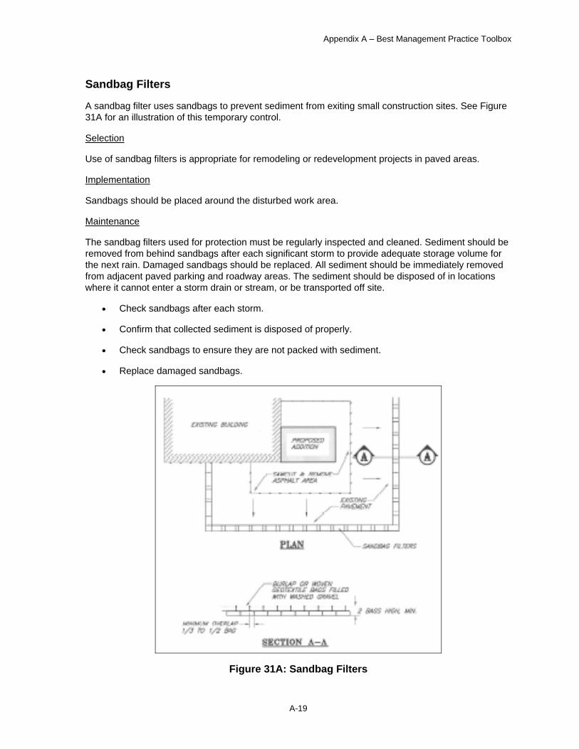
Sandbag Filters
A sandbag filter uses sandbags to prevent sediment from exiting small construction sites. See Figure 31A for an illustration of this temporary control.
Selection
Use of sandbag filters is appropriate for remodeling or redevelopment projects in paved areas.
Implementation
Sandbags should be placed around the disturbed work area.
Maintenance
The sandbag filters used for protection must be regularly inspected and cleaned. Sediment should be removed from behind sandbags after each significant storm to provide adequate storage volume for the next rain. Damaged sandbags should be replaced. All sediment should be immediately removed from adjacent paved parking and roadway areas. The sediment should be disposed of in locations where it cannot enter a storm drain or stream, or be transported off site.
• Check sandbags after each storm.
• Confirm that collected sediment is disposed of properly.
• Check sandbags to ensure they are not packed with sediment.
• Replace damaged sandbags.
Figure 31A: Sandbag Filters
Appendix A – Best Management Practice Toolbox
A-20
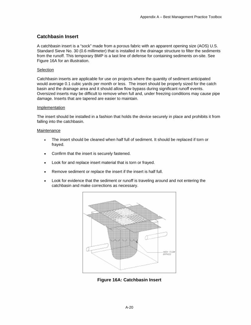
Catchbasin Insert
A catchbasin insert is a “sock” made from a porous fabric with an apparent opening size (AOS) U.S. Standard Sieve No. 30 (0.6 millimeter) that is installed in the drainage structure to filter the sediments from the runoff. This temporary BMP is a last line of defense for containing sediments on-site. See Figure 16A for an illustration.
Selection
Catchbasin inserts are applicable for use on projects where the quantity of sediment anticipated would average 0.1 cubic yards per month or less. The insert should be properly sized for the catch basin and the drainage area and it should allow flow bypass during significant runoff events. Oversized inserts may be difficult to remove when full and, under freezing conditions may cause pipe damage. Inserts that are tapered are easier to maintain.
Implementation
The insert should be installed in a fashion that holds the device securely in place and prohibits it from falling into the catchbasin.
Maintenance
• The insert should be cleaned when half full of sediment. It should be replaced if torn or frayed.
• Confirm that the insert is securely fastened.
• Look for and replace insert material that is torn or frayed.
• Remove sediment or replace the insert if the insert is half full.
• Look for evidence that the sediment or runoff is traveling around and not entering the catchbasin and make corrections as necessary.
Figure 16A: Catchbasin Insert

Appendix A – Best Management Practice Toolbox
A-21
Catchbasin Covering
Another last line of defense for containing sediments on-site, a catchbasin covering is a porous fabric with an apparent opening size (AOS) U.S. Standard Sieve No. 30 (0.6 millimeter) that removes sediment from runoff before it enters a catchbasin. See Figure 17A for an illustration of this temporary BMP.
Selection
The catchbasin covering is an applicable protection measure for all catchbasins on sites where small quantities of sediments are mobilized. It is not effective in removing large quantities of sediment because the sediment clogs the covering and requires frequent maintenance.
Implementation
Catchbasin coverings should be installed so that a sump is constructed around the catchbasin. The sump allows water velocities to slow and deposit sediments before they enter the catchbasin. The filter fabric should be installed in a manner that completely covers the catchbasin opening. The washed gravel should encircle the catchbasin and act as a filter.
Maintenance
The washed gravel should be cleaned or replaced when the catchbasin covering becomes half filled with sediments. The sump should be reshaped at the same time the washed gravel is maintained.
• Check for washed gravel that is bermed around the catchbasin.
• Look for evidence that the washed gravel is filled with sediment.
• Confirm that the filter fabric is covering the opening.
• Look for and replace filter fabric that is torn or frayed.
• Check on whether the filter fabric needs cleaning; remove as necessary.
Figure 17A: Catchbasin Covering

Appendix A – Best Management Practice Toolbox
A-22
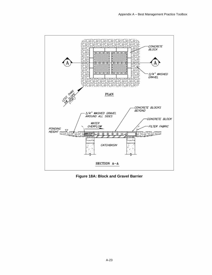
Block and Gravel Barrier
The block and gravel barrier is another type of last line of defense for containing sediments onsite. It is a filter that uses concrete blocks, gravel, and a porous fabric with an apparent opening size (AOS) U.S. Standard Sieve No. 30 (0.6 millimeter), to remove sediment from runoff prior to entering a catchbasin. See Figures 18A and 19A for illustrations of these temporary BMPs.
Selection
Block and gravel barriers are applicable for all catchbasins on sites where small quantities of sediments are mobilized. This BMP is not effective in removing large quantities of sediment because the sediment clogs the barrier and requires frequent maintenance. The block and gravel barrier BMP is also ineffective in situations in which high runoff flow occurs because the barriers become hydraulically overloaded and allow untreated runoff to enter the catchbasins. Block and gravel barriers must not be used in areas open to bicycle and motor vehicle traffic.
Implementation
The block and gravel barrier should be installed so that a sump is created by effectively raising the height of the top of the catchbasin. The blocks should hold the filter fabric securely in place. The washed gravel and blocks should encircle the catchbasin.
Maintenance
The washed gravel should be cleaned or replaced when it becomes half filled with sediments.
• Confirm that the washed gravel and blocks encircle the catchbasin.
• Check whether the washed gravel is filled with sediment.
• Look for filter fabric that is covered with sediment.
• Look for and repair filter fabric that is torn or frayed.
• Look for evidence of sediment having entered the catchbasin.
• Repair any structural damage immediately.
Appendix A – Best Management Practice Toolbox
A-23
Figure 18A: Block and Gravel Barrier
Appendix A – Best Management Practice Toolbox
A-24
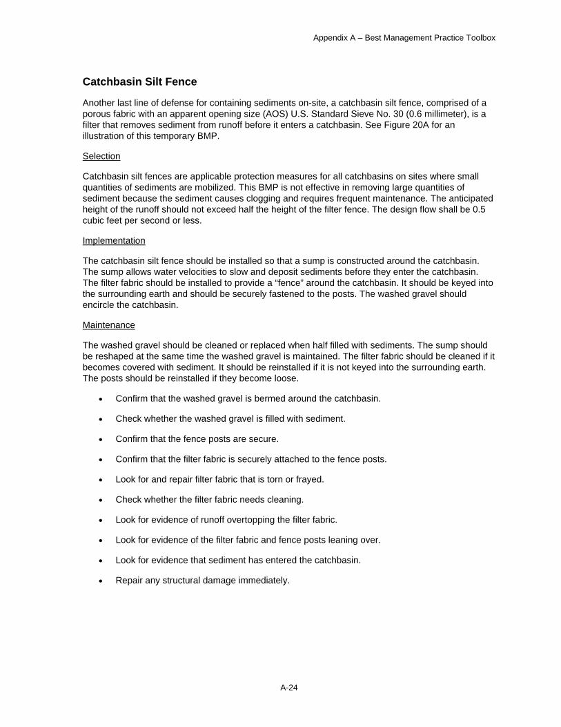
Catchbasin Silt Fence
Another last line of defense for containing sediments on-site, a catchbasin silt fence, comprised of a porous fabric with an apparent opening size (AOS) U.S. Standard Sieve No. 30 (0.6 millimeter), is a filter that removes sediment from runoff before it enters a catchbasin. See Figure 20A for an illustration of this temporary BMP.
Selection
Catchbasin silt fences are applicable protection measures for all catchbasins on sites where small quantities of sediments are mobilized. This BMP is not effective in removing large quantities of sediment because the sediment causes clogging and requires frequent maintenance. The anticipated height of the runoff should not exceed half the height of the filter fence. The design flow shall be 0.5 cubic feet per second or less.
Implementation
The catchbasin silt fence should be installed so that a sump is constructed around the catchbasin. The sump allows water velocities to slow and deposit sediments before they enter the catchbasin. The filter fabric should be installed to provide a “fence” around the catchbasin. It should be keyed into the surrounding earth and should be securely fastened to the posts. The washed gravel should encircle the catchbasin.
Maintenance
The washed gravel should be cleaned or replaced when half filled with sediments. The sump should be reshaped at the same time the washed gravel is maintained. The filter fabric should be cleaned if it becomes covered with sediment. It should be reinstalled if it is not keyed into the surrounding earth. The posts should be reinstalled if they become loose.
• Confirm that the washed gravel is bermed around the catchbasin.
• Check whether the washed gravel is filled with sediment.
• Confirm that the fence posts are secure.
• Confirm that the filter fabric is securely attached to the fence posts.
• Look for and repair filter fabric that is torn or frayed.
• Check whether the filter fabric needs cleaning.
• Look for evidence of runoff overtopping the filter fabric.
• Look for evidence of the filter fabric and fence posts leaning over.
• Look for evidence that sediment has entered the catchbasin.
• Repair any structural damage immediately.
Appendix A – Best Management Practice Toolbox
A-25
Figure 20A: Catchbasin Silt Fence

Appendix A – Best Management Practice Toolbox
A-26
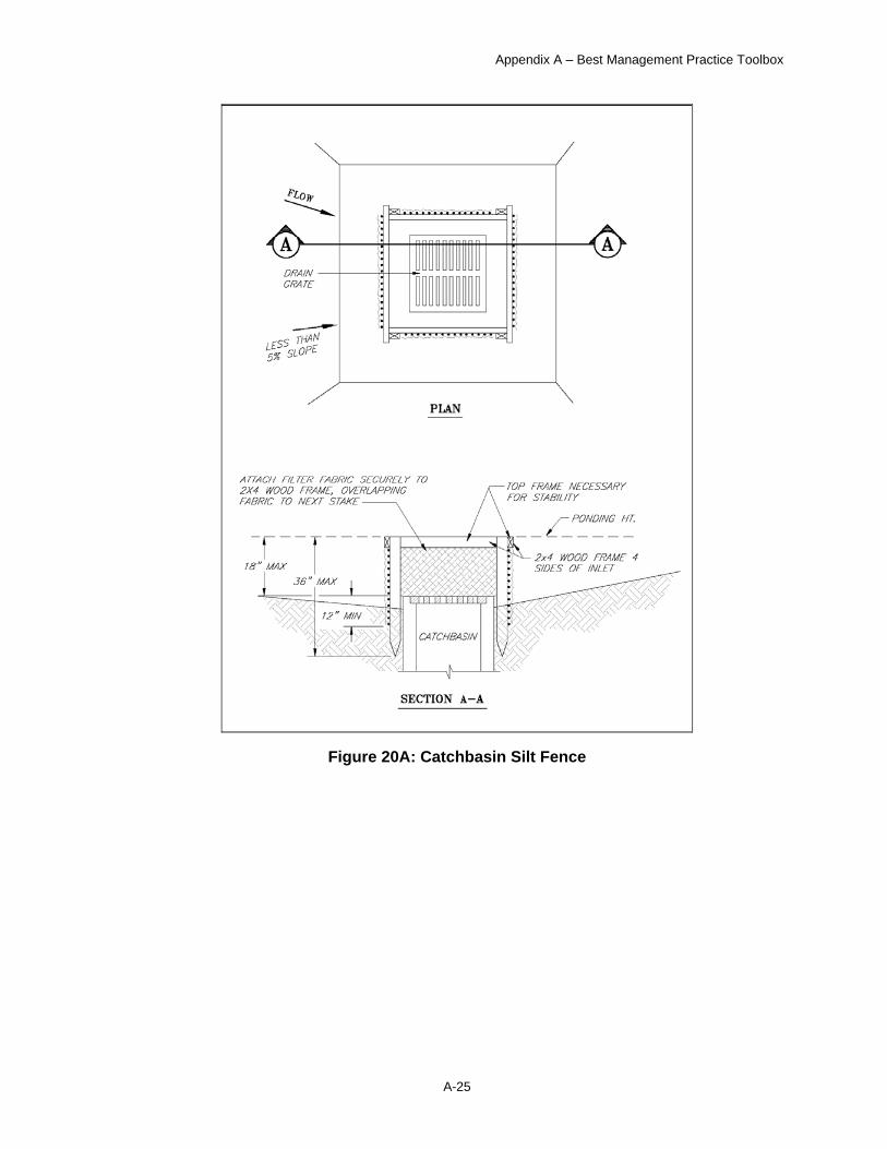
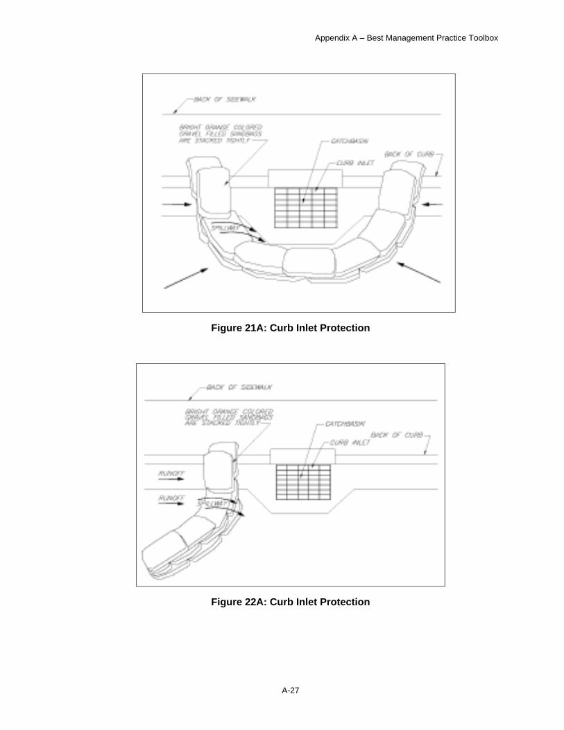
Curb Inlet Protection
Curb inlet protection uses sandbags to prevent sediment from entering curb inlet drainage structures. Figures 21A and 22A show sample installations of this temporary BMP.
Selection
Curb inlet protection must not be used in areas open to bicycle and motor vehicle traffic. Use of curb inlet protection is appropriate for construction projects near roadways with curb and gutter drainage systems that are closed to traffic.
Implementation
At a minimum, sandbags should be placed upstream of curb inlet.
Maintenance
Curb inlet protection should be inspected and cleaned regularly. Sediment should be removed from behind sandbags after each significant storm to provide adequate storage volume for the next event, and damaged sandbags should be replaced as necessary. All sediment should be removed immediately from the roadway. The sediment should be disposed of in a location where it cannot enter a storm drain or stream, or be transported off site.
• Check sandbags after each storm.
• Confirm that sandbags are not packed with sediment.
• Replace damaged sandbags.
• Remove sandbags in traveled ways before winter freeze up.
Appendix A – Best Management Practice Toolbox
A-27
Figure 21A: Curb Inlet Protection
Figure 22A: Curb Inlet Protection

Appendix A – Best Management Practice Toolbox
A-28
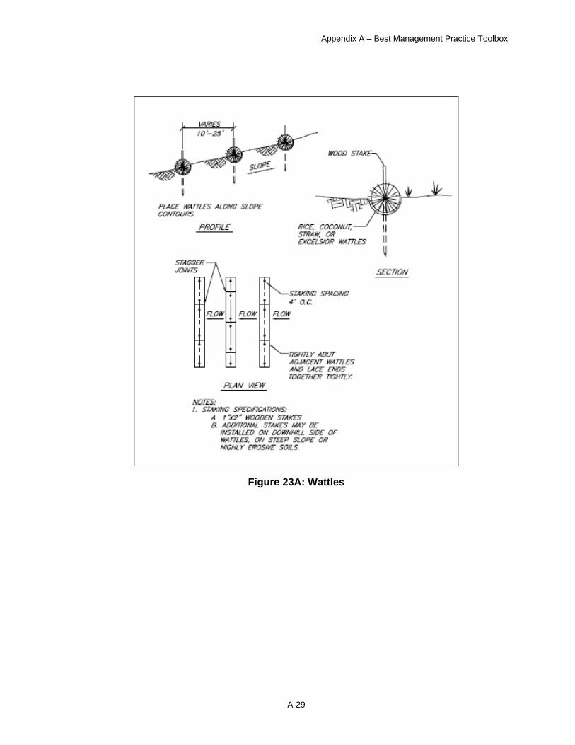
Wattles
Wattles are used to control soil erosion and to filter surface runoff leaving a construction site. Wattles are manufactured from fibers such as straw and coconut. They are typically bound into eight- or nine-inch diameter tubes that are seven to twenty-five feet long. The binding is biodegradable plastic netting allowing the whole structure to decompose over time. See Figure 23A for an illustration of this temporary BMP.
Selection
Wattles are placed in shallow trenches perpendicular to newly constructed or disturbed slopes. They are useful to break up slope length and thus reduce the potential for erosion on slopes susceptible to sheet and rill erosion.
The use of wattles treated with chemical coagulants or flocculants must be stated in the SWPPP and the location shown on the site plan. Treated wattles will not be allowed near storm drain inlets and at project site stormwater discharge points.
Implementation
Trenches should be deep enough to accommodate half the diameter of the wattle. Wattles must be staked a minimum of every four feet but may require more staking in order to hold them tightly to the soil. Stakes should extend twelve inches into undisturbed soil. Wattles can be left in place to biodegrade. This is a particularly appealing option when live willow stakes have been used in place of rebar or wood stakes. The wattle will hold moisture to help the willow get established, and then will slowly decompose as the plant grows. Wattles can be used in place of silt fences on steep slopes.
Maintenance
Wattles should be inspected once per week on active construction sites, and every two weeks on inactive sites. In addition to this regular inspection routine, inspections should be made after any rainfall event greater than half an inch. Wattles that are no longer in contact with the soil should be restaked. If a wattle becomes too sediment laden to filter runoff then it should be replaced.
• Check that the wattle is properly staked and is in tight contact with the soil surface beneath.
• After significant rainstorms, check for erosion and undermining.
• Check that wattles are securely fastened together.
Appendix A – Best Management Practice Toolbox
A-29
Figure 23A: Wattles
Appendix A – Best Management Practice Toolbox
A-30
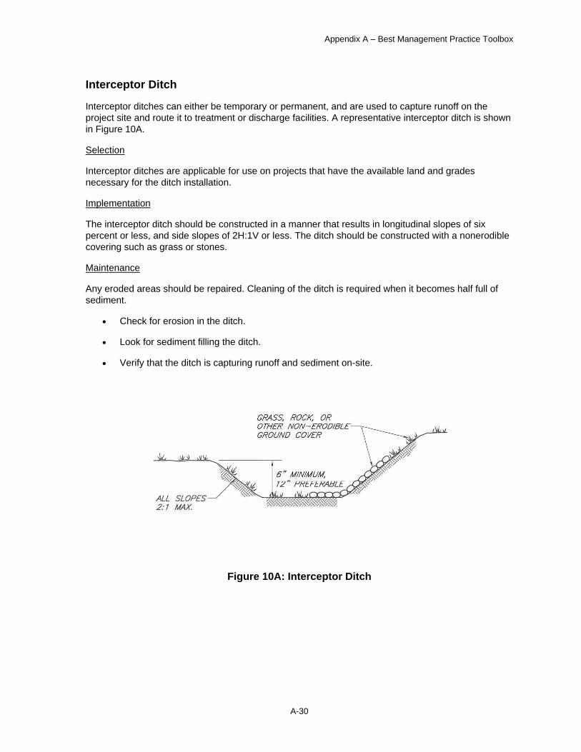
Interceptor Ditch
Interceptor ditches can either be temporary or permanent, and are used to capture runoff on the project site and route it to treatment or discharge facilities. A representative interceptor ditch is shown in Figure 10A.
Selection
Interceptor ditches are applicable for use on projects that have the available land and grades necessary for the ditch installation.
Implementation
The interceptor ditch should be constructed in a manner that results in longitudinal slopes of six percent or less, and side slopes of 2H:1V or less. The ditch should be constructed with a nonerodible covering such as grass or stones.
Maintenance
Any eroded areas should be repaired. Cleaning of the ditch is required when it becomes half full of sediment.
• Check for erosion in the ditch.
• Look for sediment filling the ditch.
• Verify that the ditch is capturing runoff and sediment on-site.
Figure 10A: Interceptor Ditch

Appendix A – Best Management Practice Toolbox
A-31
Temporary Diversion Dike
A temporary diversion dike is a channel constructed across a slope with an excavated ditch, a compacted berm, or both in combination. Most diversions are constructed by excavating a ditch and using the excavated material to construct a berm on the downhill side. Diversion dikes may be either temporary or permanent. This BMP is illustrated in Figure 11A.
Selection
Use of a temporary diversion dike works well on sites where storm water runoff can be redirected to protect areas from erosion and sediment. Temporary diversion dikes are used to temporarily divert storm water runoff to protect disturbed areas and slopes, or to retain sediment on-site during construction. This measure should be used in construction areas where runoff can be diverted and disposed of properly to control erosion, sedimentation, or flood damage. Berms to intercept and divert runoff should not be used where the drainage area exceeds 10 acres. Diversion dikes should be carefully designed where ditch slopes are steeper than 10 percent.
Implementation
Temporary diversion dikes should be designed so that the runoff velocities are high enough to create self-cleaning flows so that sediment deposition in the channel is minimized. Compact the berm to prevent unequal settlement and to provide stability against seepage. Stabilize the diversion after installation.
Maintenance
Temporary diversion dikes should be inspected periodically for erosion damage, especially after heavy rainfall. Sediment should immediately be removed from the flow area. Outlet areas should be checked, and timely repairs should be made as needed.
• Look for flow impediments in the channel.
• Check for erosion at the outfall.
• Remove trash accumulations.
• Check for sediment accumulations; remove when deeper than 2 inches.
Figure 11A: Temporary Diversion Dike
Appendix A – Best Management Practice Toolbox
A-32
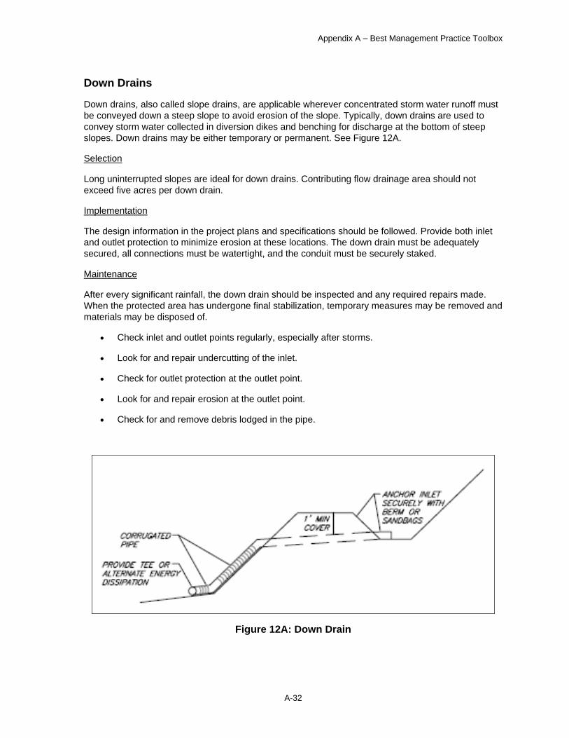
Down Drains
Down drains, also called slope drains, are applicable wherever concentrated storm water runoff must be conveyed down a steep slope to avoid erosion of the slope. Typically, down drains are used to convey storm water collected in diversion dikes and benching for discharge at the bottom of steep slopes. Down drains may be either temporary or permanent. See Figure 12A.
Selection
Long uninterrupted slopes are ideal for down drains. Contributing flow drainage area should not exceed five acres per down drain.
Implementation
The design information in the project plans and specifications should be followed. Provide both inlet and outlet protection to minimize erosion at these locations. The down drain must be adequately secured, all connections must be watertight, and the conduit must be securely staked.
Maintenance
After every significant rainfall, the down drain should be inspected and any required repairs made. When the protected area has undergone final stabilization, temporary measures may be removed and materials may be disposed of.
• Check inlet and outlet points regularly, especially after storms.
• Look for and repair undercutting of the inlet.
• Check for outlet protection at the outlet point.
• Look for and repair erosion at the outlet point.
• Check for and remove debris lodged in the pipe.
Figure 12A: Down Drain

Appendix A – Best Management Practice Toolbox
A-33
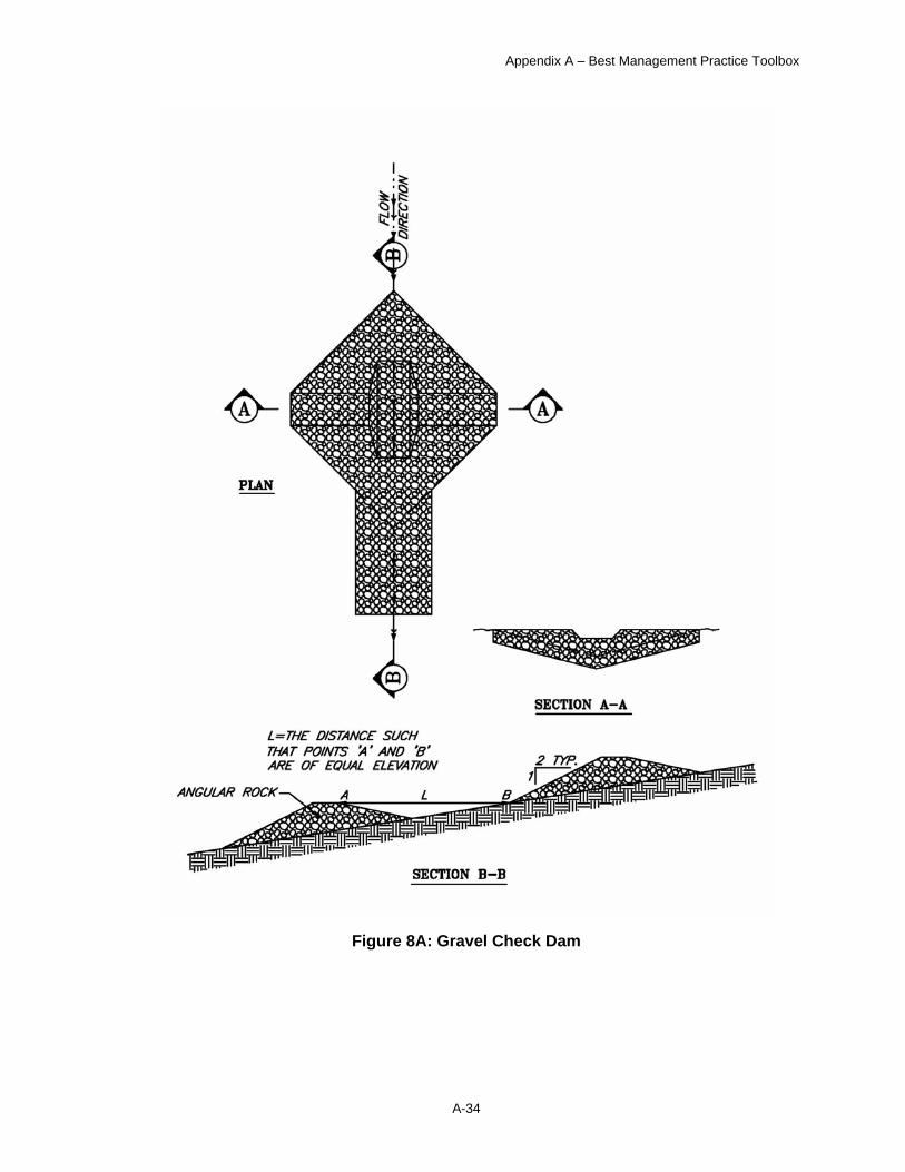
Gravel Check Dam
Gravel check dams are used to reduce the velocity of the runoff in a ditch as shown in Figure 8A. By reducing the velocity of the runoff, they reduce the potential for ditch erosion. Gravel check dams can be both a temporary or permanent control measure.
Selection
Gravel check dams are appropriate for any ditch where the runoff velocity is no greater than 6 feet per second. Check dams installed in grass lined structures may kill the vegetative lining if siltation is excessive or the dam remains submerged for extended periods of time. Rock check dams are used in narrow ditches and gullies. Straw bales are used primarily in wide swales.
Implementation
Gravel check dams should be constructed from angular rock, sized for the design flow velocity (refer to the MOA Design Criteria Manual Chapter 2). They should be keyed into the surrounding earth to prevent erosion. The check dams should be placed closer together on steeper slopes. The layout of the check dams must be done in a manner that overtopping of the ditch does not occur. Runoff from the contributing drainage area should be evaluated along with expected velocities in order to assure appropriate BMP design.
Maintenance
Cleaning is required if the rocks become half full of sediment. If the earth near the check dam is eroded, the area must be stabilized with rocks or other materials.
• Look for sediment filling the check dam.
• Check to see if the area near the check dam is eroded.
• Look for erosion in the ditch between check dams.
• Check for overtopping of the ditch.
• Repair check dam voids and undercuts.
Appendix A – Best Management Practice Toolbox
A-34
Figure 8A: Gravel Check Dam

Appendix A – Best Management Practice Toolbox
A-35
Storm Drain Diffuser
Storm drain diffusers are useful in areas where drainage systems do not exist to address concentrated runoff from a site. Figure 29A shows plan and section views of a storm drain diffuser. A storm drain diffuser can function as both a temporary and permanent measure.
Selection
Storm drain diffusers are used when a concentrated flow of water needs to be dispersed over a large area with existing stable vegetation.
Implementation
The outflow must be essentially level to work correctly. Care must be taken to not create a surcharged drainage system or a system that does not drain entirely.
Maintenance
The diffuser should be inspected after every runoff event to ensure that it is functioning correctly.
• Look for and remove trash accumulation in the diffuser.
• Look for and remove sediment accumulation in the diffuser.
• Check for and repair erosion on the diffuser outlet.
• Check the drainage system for blockages and clear any blockage.
• Confirm that the system drains properly before freeze-up.
Figure 29A: Storm Drain Diffuser

Appendix A – Best Management Practice Toolbox
A-36
Outlet Protection
Outlet protection can be either a temporary or permanent control that prevents scour at pipe outlets and reduces the velocity of the concentrated discharge. Guidelines for implementation of outlet protection are shown in Figure 9A.
Selection
Outlet protection is applicable wherever high-velocity discharge must be released on erodible soils. A lined apron is the most commonly used practice for this purpose because of its low cost and ease of installation. Select the gravel or riprap diameter based on the design flow velocity (refer to the MOA Design Criteria Manual Chapter 2). Stilling basins or plunge pools should be considered in lieu of aprons where pipe outlets are perched or where high flows would require excessive apron length.
Implementation
The installation must conform to the required lines and grades shown in the plan. All elements of the outlet protection installation should follow the plans and specifications. Designs will vary based on discharge specifics and receiving area conditions.
Maintenance
Outlet protection should be inspected after heavy rains to see if any erosion has occurred or if rock has been dislodged. All repairs should be made immediately to prevent further damage.
• Look for and correct erosion at the outlet.
• Check that rocks are in place and replace them as necessary.
• Ensure that any geotextile installed is in working order.
• Remove sediment when it fills the voids between rocks.

Appendix A – Best Management Practice Toolbox
A-37
Figure 9A: Outlet Protection

Appendix A – Best Management Practice Toolbox
A-38
Stockpile Topsoil and Reapply to Revegetate Site
Because of the high organic content of topsoil, it cannot be used as fill material or under pavement, and is typically removed. Since topsoil is essential to establish new vegetation, it should be stockpiled and then reapplied to the site for revegetation, if appropriate. Unprotected stockpiles are very prone to erosion and therefore must be protected. Small stockpiles can be covered with a tarp to prevent erosion. Large stockpiles should be stabilized by erosion blankets, seeding, and/or mulching.

Appendix A – Best Management Practice Toolbox
A-39
Concrete Washout
Concrete waste management includes procedures and practices that minimize or eliminate the discharge of concrete waste materials to the storm drain systems or watercourses.
Selection
Concrete washout facilities should be considered on construction projects where
• Slurries containing Portland cement concrete (PCC) or asphalt concrete (AC) are generated, such as from sawcutting, coring, grinding, grooving, and hydro-concrete demolition
• Concrete trucks and other concrete-coated equipment are washed on site, and
• Mortar-mixing stations exist. Implementation
• Temporary concrete washout facilities shall be located a minimum of 50 ft from storm drain inlets, open drainage facilities, and watercourses,
• Each facility shall be located away from construction traffic or access areas to prevent disturbance or tracking.
• Install a sign adjacent to each washout facility to inform concrete equipment operators to utilize the proper facilities.
• Plastic lining material shall be a minimum of 10-mil polyethylene sheeting and shall be free of holes, tears or other defects that compromise the impermeability of the material.
• The soil base shall be prepared free of rocks or other debris that may cause tears or holes in the plastic lining material.
• Temporary washout facilities shall have a temporary pit or bermed areas of sufficient volume to completely contain all liquid and waste concrete materials generated during washout procedures.
Maintenance
• Supervise onsite concrete working tasks, such as saw cutting, coring, grinding and grooving to ensure proper methods are implemented.
• Vacuum slurry residue and dispose in a temporary facility and allow slurry to dry. Dispose of dry slurry residue and concrete wastes as solid waste.
• Temporary concrete washout facilities shall be maintained to provide adequate holding capacity with a minimum freeboard of 4 inches for above grade facilities and 2 inches for below grade facilities.
• Maintaining temporary concrete washout facilities shall include removing and disposing of hardened concrete and returning the facilities to a functional condition.
• Existing facilities must be cleaned, or new facilities must be constructed and ready for use once the washout is 75% full.
• Temporary concrete washout facilities shall be inspected for damage (i.e. tears in PVC liner, missing sand bags, etc.). Damaged facilities shall be repaired.

Appendix A – Best Management Practice Toolbox
A-40
Dewatering Controls
Definition and Purpose
Dewatering controls are practices that manage the discharge of pollutants when non-storm water and accumulated precipitation (storm water) must be removed from a work location so that construction work may be accomplished. Controls are required to ensure that water that is discharged to surface waterbodies or the storm drain system meets water quality standards and does not cause erosion or flooding.
Appropriate Applications
• These practices are implemented for discharges of non-storm water and storm water (accumulated rain water) from construction sites. Non-storm water includes, but is not limited to, groundwater, dewatering of piles, water from cofferdams, water diversions, and water used during construction activities that must be removed from a work area.
• Practices identified in this section are also appropriate for implementation when managing the removal of accumulated precipitation (storm water) from depressed areas at a construction site.
• Excavation dewatering options include:
− Haul it off for proper disposal elsewhere
− Discharge to sanitary sewer (requires permit from AWWU)
− Discharge clean water to storm sewer (requires permit from MOA)
− Discharge to uplands or areas that provide infiltration and no runoff to surface waters
− Install well points and discharge clean water
− Provide for settling prior to discharge to storm sewer (requires permit from MOA) or waterbody
− Provide filtration prior to discharge to storm sewer (requires permit from MOA) or waterbody
• A dewatering plan shall be submitted as part of the SWPPP detailing the location of dewatering activities, equipment, and discharge point. PM&E may require that the planned be stamped by a registered engineer.
Limitations
• Dewatering operations for non-storm water will require, and must comply with, applicable state permits, project-specific permits, and regulations.
• Discharges to surface water must comply with state of Alaska Water Quality Standards, which can be found in 18 Alaska Administrative Code 70.020.
• Coverage under the Alaska Department of Environmental Conservation (ADEC) General Permit for excavation dewatering is required for discharges that don’t otherwise have coverage under the EPA NPDES CGP. Written authorization from ADEC for the ADEC permit is required for sites within 1 mile of a contaminated site for discharges greater than 250,000 gallons (over the life of the project). More information can be found at http://www.dec.state.ak.us/water/wwdp/online_permitting/ind_ww_apps.htm
• Site conditions will dictate design and use of dewatering operations.
• Removal efficiency by settling (sedimentation) depends on particle size, flow rate, water temperature, and other factors. This may not be a treatment option if soil particles are fine. Consult the Design Criteria Manual for additional information on design of sedimentation facilities.
• The controls discussed in this best management practice (BMP) address sediment only. If the presence of polluted water with hazardous substances is identified in the contract, the contractor shall contact the ADEC. If the quality of water to be removed by dewatering is not identified as

Appendix A – Best Management Practice Toolbox
A-41
polluted in the dewatering plan, but is later determined by observation or testing to be polluted, the contractor shall notify PM&E and ADEC.
• Avoid dewatering discharges where possible by using the water for dust control, by infiltration, etc.
• Dewatering discharges must not cause flooding or erosion at the discharge point. • Dewatering records shall be maintained for a period of 3 years.
Maintenance and Inspection
• Inspect all BMPs implemented to comply with permit requirements frequently and repair or replace to ensure the BMPs function as designed.
• Conduct water quality monitoring pursuant to the “Storm Water Dewatering Operations BMP Discharge Monitoring Forms”.
• Accumulated sediment removed during the maintenance of a dewatering device may be incorporated in the project at locations designated in the dewatering plan or disposed of outside the right-of-way in conformance with applicable laws and regulations.
• Accumulated sediment that is commingled with other pollutants must be disposed of in accordance with all applicable laws and regulations.
• Assure that there is no downstream flooding if discharges are made to storm sewers, creeks, or streams.
Summary of Water Quality Standards (see 18 Alaska Administrative code 70.200.)
Maximum Concentrations in Dewatering Effluent Indicator Maximum Concentration or value Turbidity 5 nephelometric turbidity units above natural conditions Total aqueous hydrocarbons 15 microgram/liter Total aromatic hydrocarbons 10 micrograms/liter Settleable solids 0.2 milliliters per liter pH Between 6.5 and 8.5 pH units Additives, such as antifreeze or solvents None in detectable amounts Toxic substances None in detectable amounts Sheen due to grease and oils None in detectable amounts Foam in other than trace amounts None Garbage, debris, or other contaminants None in detectable amounts
Sediment Treatment
A variety of methods can be used to treat water during dewatering. Several devices are presented in this section that provide options to achieve sediment removal. The size of particles present in the sediment and receiving water quality limitations are key considerations for selecting sediment treatment option(s); in some cases, the use of multiple devices may be appropriate.
Appendix A – Best Management Practice Toolbox
A-42
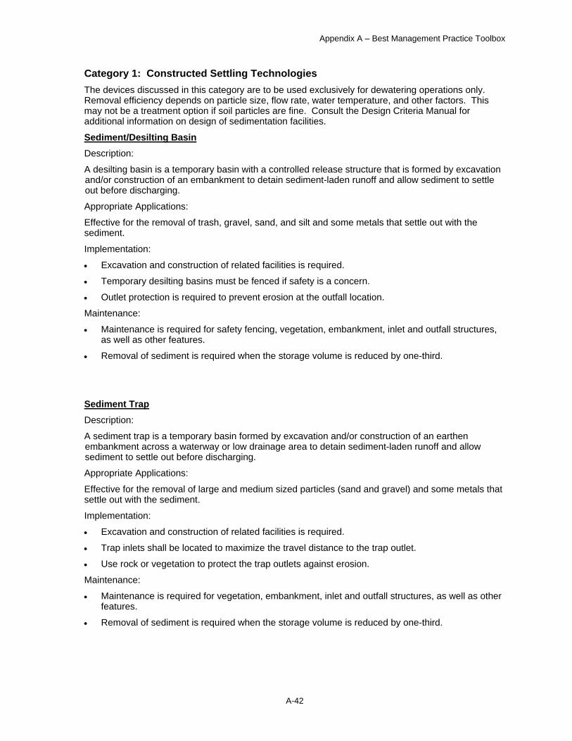
Category 1: Constructed Settling Technologies The devices discussed in this category are to be used exclusively for dewatering operations only. Removal efficiency depends on particle size, flow rate, water temperature, and other factors. This may not be a treatment option if soil particles are fine. Consult the Design Criteria Manual for additional information on design of sedimentation facilities.
Sediment/Desilting Basin Description:
A desilting basin is a temporary basin with a controlled release structure that is formed by excavation and/or construction of an embankment to detain sediment-laden runoff and allow sediment to settle out before discharging.
Appropriate Applications:
Effective for the removal of trash, gravel, sand, and silt and some metals that settle out with the sediment.
Implementation:
• Excavation and construction of related facilities is required.
• Temporary desilting basins must be fenced if safety is a concern.
• Outlet protection is required to prevent erosion at the outfall location.
Maintenance:
• Maintenance is required for safety fencing, vegetation, embankment, inlet and outfall structures, as well as other features.
• Removal of sediment is required when the storage volume is reduced by one-third.
Sediment Trap Description:
A sediment trap is a temporary basin formed by excavation and/or construction of an earthen embankment across a waterway or low drainage area to detain sediment-laden runoff and allow sediment to settle out before discharging.
Appropriate Applications:
Effective for the removal of large and medium sized particles (sand and gravel) and some metals that settle out with the sediment.
Implementation:
• Excavation and construction of related facilities is required.
• Trap inlets shall be located to maximize the travel distance to the trap outlet.
• Use rock or vegetation to protect the trap outlets against erosion.
Maintenance:
• Maintenance is required for vegetation, embankment, inlet and outfall structures, as well as other features.
• Removal of sediment is required when the storage volume is reduced by one-third.
Appendix A – Best Management Practice Toolbox
A-43
Category 2: Mobile Settling Technologies These devices are typical of tanks that can be used for sediment treatment of dewatering operations.
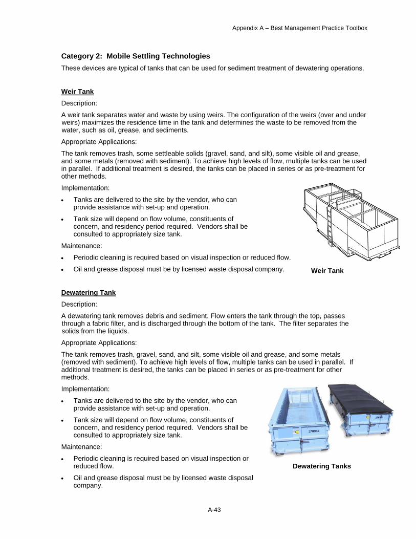
Weir Tank Description:
A weir tank separates water and waste by using weirs. The configuration of the weirs (over and under weirs) maximizes the residence time in the tank and determines the waste to be removed from the water, such as oil, grease, and sediments. Appropriate Applications:
The tank removes trash, some settleable solids (gravel, sand, and silt), some visible oil and grease, and some metals (removed with sediment). To achieve high levels of flow, multiple tanks can be used in parallel. If additional treatment is desired, the tanks can be placed in series or as pre-treatment for other methods.
Implementation:
• Tanks are delivered to the site by the vendor, who can provide assistance with set-up and operation.
• Tank size will depend on flow volume, constituents of concern, and residency period required. Vendors shall be consulted to appropriately size tank.
Maintenance: • Periodic cleaning is required based on visual inspection or reduced flow.
• Oil and grease disposal must be by licensed waste disposal company.
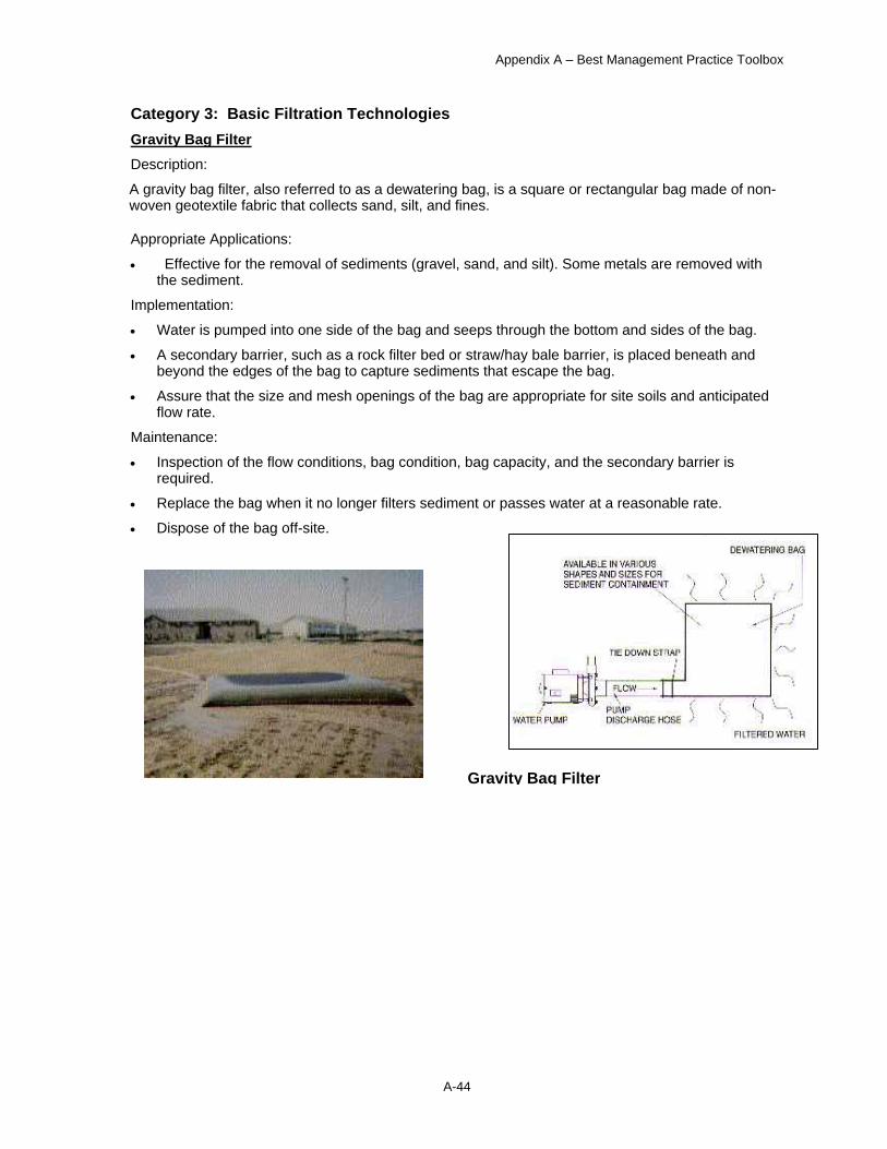
Dewatering Tank Description:
A dewatering tank removes debris and sediment. Flow enters the tank through the top, passes through a fabric filter, and is discharged through the bottom of the tank. The filter separates the solids from the liquids.
Appropriate Applications:
The tank removes trash, gravel, sand, and silt, some visible oil and grease, and some metals (removed with sediment). To achieve high levels of flow, multiple tanks can be used in parallel. If additional treatment is desired, the tanks can be placed in series or as pre-treatment for other methods. Implementation:
• Tanks are delivered to the site by the vendor, who can provide assistance with set-up and operation.
• Tank size will depend on flow volume, constituents of concern, and residency period required. Vendors shall be consulted to appropriately size tank.
Maintenance:
• Periodic cleaning is required based on visual inspection or reduced flow.
• Oil and grease disposal must be by licensed waste disposal company.
Weir Tank
Dewatering Tanks
Appendix A – Best Management Practice Toolbox
A-44
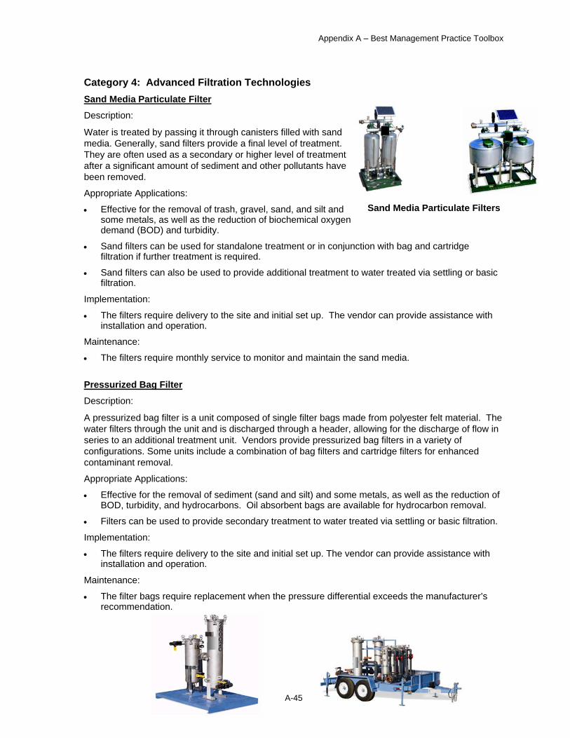
Category 3: Basic Filtration Technologies Gravity Bag Filter Description:
A gravity bag filter, also referred to as a dewatering bag, is a square or rectangular bag made of non-woven geotextile fabric that collects sand, silt, and fines.
Appropriate Applications:
• Effective for the removal of sediments (gravel, sand, and silt). Some metals are removed with the sediment.
Implementation:
• Water is pumped into one side of the bag and seeps through the bottom and sides of the bag.
• A secondary barrier, such as a rock filter bed or straw/hay bale barrier, is placed beneath and beyond the edges of the bag to capture sediments that escape the bag.
• Assure that the size and mesh openings of the bag are appropriate for site soils and anticipated flow rate.
Maintenance:
• Inspection of the flow conditions, bag condition, bag capacity, and the secondary barrier is required.
• Replace the bag when it no longer filters sediment or passes water at a reasonable rate.
• Dispose of the bag off-site.
Gravity Bag Filter
Appendix A – Best Management Practice Toolbox
A-45
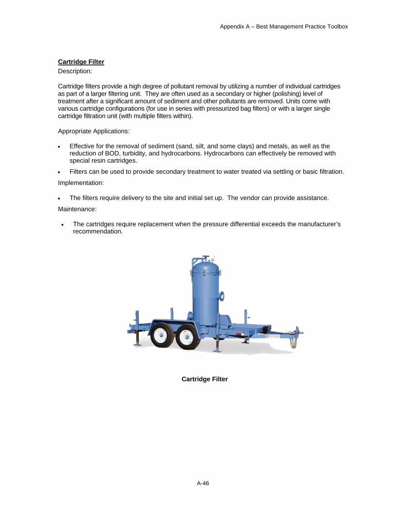
Category 4: Advanced Filtration Technologies Sand Media Particulate Filter
Description:
Water is treated by passing it through canisters filled with sand media. Generally, sand filters provide a final level of treatment. They are often used as a secondary or higher level of treatment after a significant amount of sediment and other pollutants have been removed.
Appropriate Applications:
• Effective for the removal of trash, gravel, sand, and silt and some metals, as well as the reduction of biochemical oxygen demand (BOD) and turbidity.
• Sand filters can be used for standalone treatment or in conjunction with bag and cartridge filtration if further treatment is required.
• Sand filters can also be used to provide additional treatment to water treated via settling or basic filtration.
Implementation:
• The filters require delivery to the site and initial set up. The vendor can provide assistance with installation and operation.
Maintenance:
• The filters require monthly service to monitor and maintain the sand media.
Pressurized Bag Filter
Description:
A pressurized bag filter is a unit composed of single filter bags made from polyester felt material. The water filters through the unit and is discharged through a header, allowing for the discharge of flow in series to an additional treatment unit. Vendors provide pressurized bag filters in a variety of configurations. Some units include a combination of bag filters and cartridge filters for enhanced contaminant removal.
Appropriate Applications:
• Effective for the removal of sediment (sand and silt) and some metals, as well as the reduction of BOD, turbidity, and hydrocarbons. Oil absorbent bags are available for hydrocarbon removal.
• Filters can be used to provide secondary treatment to water treated via settling or basic filtration.
Implementation:
• The filters require delivery to the site and initial set up. The vendor can provide assistance with installation and operation.
Maintenance: • The filter bags require replacement when the pressure differential exceeds the manufacturer’s
recommendation.
Sand Media Particulate Filters
Appendix A – Best Management Practice Toolbox
A-46
Cartridge Filter Description:
Cartridge filters provide a high degree of pollutant removal by utilizing a number of individual cartridges as part of a larger filtering unit. They are often used as a secondary or higher (polishing) level of treatment after a significant amount of sediment and other pollutants are removed. Units come with various cartridge configurations (for use in series with pressurized bag filters) or with a larger single cartridge filtration unit (with multiple filters within).
Appropriate Applications:
• Effective for the removal of sediment (sand, silt, and some clays) and metals, as well as the reduction of BOD, turbidity, and hydrocarbons. Hydrocarbons can effectively be removed with special resin cartridges.
• Filters can be used to provide secondary treatment to water treated via settling or basic filtration.
Implementation:
• The filters require delivery to the site and initial set up. The vendor can provide assistance.
Maintenance:
• The cartridges require replacement when the pressure differential exceeds the manufacturer’s recommendation.
Cartridge Filter

Appendix A – Best Management Practice Toolbox
A-47
DEWATERING OPERATIONS DISCHARGE MONITORING FORM
GENERAL INFORMATION
Project Name
Operator
Location
Sampler’s Name
Sampler’s Signature
Date Discharge Began Date of Sampling
Size of Pump Hours of operation
Time pump started Time pump shut off
WATER SAMPLE LOG
Constituent Units Sample Results
Turbidity NTUs
One sample shall be taken at a point representative of discharge prior to its entering the receiving water. A second sample shall be taken of the receiving water upstream of the discharge point or in the case of receiving waters with low or no flow, prior to discharge at a location representative of the receiving water. Both samples shall be taken during the same day within a reasonable timeframe (i.e., thirty minutes).
DISCHARGE LIMITATION (See Alaska Water Quality Standards in 18 Alaska Administrative Code 70.200)
Constituent Units Receiving Water
pH Standard between 6.5 and 8.5
Turbidity NTUs 5 NTU above background
Notes:

Appendix A – Best Management Practice Toolbox
A-48
Dust Control
Dust control is a temporary BMP that is necessary during dry periods when soil is exposed to wind. This BMP prevents dust from leaving disturbed soil surfaces and falling onto surface waters, which causes sedimentation.
Selection
Dust control is necessary on construction haul routes and disturbed areas.
Implementation
The most common method for dust control is application of water to exposed soil surfaces to reduce the generation of dust, with re-application as needed. Alternate dust control methods include covering and acrylic soil treatments.
Other soil treatments may be acceptable; check with PM&E.

Appendix A – Best Management Practice Toolbox
A-49
Sweeping
Street sweeping is an effective temporary BMP to prevent construction mud and sediment from entering the storm water collection system.
Selection
All construction sites shall institute sweeping or equivalent measures to ensure that sediment and mud is not tracked onto roadways.
Implementation • The haul route within a 500-foot radius of the construction exit, or further as required, shall be
cleaned from curb to curb thoroughly at the end of each day, and more often as necessary to ensure that sediment and mud is not tracked onto roadways.
• The entire haul route shall be cleaned thoroughly from curb to curb each week. • Sediment shall be removed from roads by shoveling or pickup sweeping and shall be
transported to a controlled sediment disposal area. Street washing will be allowed only after sediment is removed in this manner.
• Street sweeping equipment, such as vacuum trucks, must be equipped with an effective baghouse or other filtering devices. The use of sweeping equipment with air pollution control devices that are in disrepair is prohibited.
• Mechanical devices without filtering equipment may be used only when wet sweeping methods are effectively employed.
• Vacuum sweepers must be used with water. • The use of leaf blowers and other similar equipment for sweeping is prohibited. • Manual broom sweeping is allowed • Reasonable measures must be employed to prevent dust from becoming airborne during any
operation where particulate matter is handled, transported or stored. • Control dust and particulate matter to comply with MOA fugitive emissions standards (AMC
15.35.090).
Maintenance
• Each hour during hauling operations, check to see that sediment and mud are not tracked onto the roadways.

Appendix A – Best Management Practice Toolbox
A-50
Gravel Construction Exit
The gravel construction exit is used to reduce mud and sediment on a roadway adjacent to a construction site. Figure 13A illustrates this BMP. The gravel acts to remove the excess dirt on dump trucks as they travel across the bumpy surface. Gravel construction exists are a temporary measure used during construction. The effectiveness of this BMP is enhanced when used with a truck wash basin.
Selection
Gravel construction exits are appropriate on all projects where soil is being hauled from the site. Mud on a road can create a safety hazard as well as a sediment problem. If the exit is not preventing sediment from being tracked onto pavement, then alternative measures to keep the streets free of sediment shall be used. This will include street sweeping, an increase in the dimensions of the entrance, or the installation of a truck wash basin.
Implementation
The gravel construction exits should be installed at all construction site exits in a manner that minimizes sediment leaving the site. They should not be placed at locations that have steep grades or at curves in public roads where sight distance may be a problem. Rocks should be installed so that a bumpy and rough surface is created.
Maintenance
The gravel construction exit should be cleaned or replaced as needed. Remove all mud and sediment deposited on paved roadways within 24 hours.
• Check for and remove dirt present on roadways adjacent to the site.
• Verify that the dump trucks leaving the site are using the exit.
• Confirm that the surface is rough and bumpy.
• Check for sediment that has accumulated in the rocks. Replace or provide additional gravel as necessary.
Figure 13A: Gravel Construction Exit
Area of
Disturbance Minimum Length
Less than 10,000 square feet 25 feet
10,000 square feet or more 50 feet

Appendix A – Best Management Practice Toolbox
A-51
Truck Wheel Wash Basin
Truck wheel wash basins are a temporary measure for removing dirt and debris from dump trucks to reduce tracking of sediment onto roadways adjacent to the construction site. An illustration is shown in Figure 14A. The basins are most effective when used in combination with a gravel construction exit.
Selection
Truck wheel wash basins are appropriate on all projects where soil is being hauled from the site.
Implementation
The truck wheel wash basin should be installed at all construction site egress points in a manner that keeps sediments from leaving the site. The rocks should be installed so that a bumpy and rough surface is created. Construction of the truck wash basin should prevent the water from overflowing the basin.
Maintenance
The truck wash basin water should be replaced weekly or more frequently as necessary to clean the trucks. The rocks should be cleaned or replaced as needed.
• Check for dirt present on roadways adjacent to site.
• Verify that dump trucks leaving the site are using the basin.
• Check for and correct water overflowing the basin.
• Check on whether the water needs changing.
• Look for the accumulation of sediment in the rocks and remove or add additional gravel as necessary.
• Confirm that the basin is rough and bumpy.
Figure 14A: Truck Wheel Wash Basin

Appendix A – Best Management Practice Toolbox
A-52
Mud Mats
Mud mats are a temporary measure for providing parking on dirt surfaces to reduce tracking of sediment onto roadways adjacent to the construction site. The mats are most effective when used in on flat slopes with light to moderate traffic.
Selection
Mud mats are appropriate on projects where worker parking is not provided in stabilized areas.
Implementation
Mud mats should be installed at all dirt parking areas in a manner that keeps sediments from leaving the site, either by foot or on vehicle wheels. The mats should be installed so that the entire area that may be used for parking or driving is covered..
Maintenance
The mud mat should be inspected weekly or more frequently as necessary to assure proper coverage and usage. The mats should be cleaned or replaced as needed.
• Check for dirt present on roadways adjacent to site.
• Verify that workers are parking in designated areas.
• Check on whether the mats need changing or sweeping.

Appendix A – Best Management Practice Toolbox
A-53
Sedimentation Basin
Sedimentation basins are used to remove large quantities of sediment from runoff. The basins can be designed to remove fine-grained sediments such as clays or silts as well as some chemicals through physical, chemical, and biological processes. The basins can also serve a dual function for runoff detention. Figure 28A shows a representative installation of this temporary and permanent BMP. Design criteria for permanent sedimentation basins are available in the MOA DCM.
Selection
Sedimentation basins are generally used on medium- to large-scale projects, and where sediment discharge would damage environmentally sensitive areas such as wetlands or streams.
Implementation
The sedimentation basin should be installed according to the plans and specifications, and if required, the SWPPP. Because the facilities are customized for each project, the approved construction plans provide the best source of information on implementation. The engineer who stamped the plans should be consulted for any clarification. Design temporary sedimentation basins for projects requiring Type 2 or Type 3 SWPPPs based on the 2-year 24-hour rainfall event. Design and calculations for permanent sedimentation basins should follow the guidance in latest edition of the MOA DCM.
Maintenance
Sediment should be removed from the sedimentation basin yearly or when it accumulates to a depth of one foot. More frequent cleanings should occur if sediment impairs the function of the outlet structure. Rocks and washed gravel should be cleaned or replaced when they become filled with sediment. If sloughing or erosion of side slopes occurs, the sedimentation basin should be repaired.
• Confirm that the construction plans have been followed.
• Check that sediment accumulation is within acceptable limits.
• Confirm that the outlet structure is functioning properly.
• Confirm that sediment is not “passing through” to downstream end.
• Check for accumulations of floating debris.
• Check to ensure that the emergency overflow spillway is not obstructed.

Appendix A – Best Management Practice Toolbox
A-54
Figure 28A: Sedimentation Basin

Appendix A – Best Management Practice Toolbox
A-55
Proprietary Oil and Grit Separator
Many proprietary oil grit separators (OGS) are available. Most of the devices remove oil and sediments through plates, baffles, filters, vortices, or a combination of these elements. A sample illustration of this permanent BMP is shown in Figure 25A. Design criteria are available in the MOA DCM.
Selection
The design engineer is responsible for selecting the appropriate device and for the proper sizing. In general, OGS devices are available to handle most applications.
Implementation
The OGS should be installed according to the plans, specifications, and manufacturer’s information. The engineer that prepared the design should be consulted if any questions arise or if further information is needed.
Maintenance
OGS devices require frequent cleaning, at least once a month during construction, and at least twice a year thereafter. Depending on the system, cleaning usually involves removal of floating debris, sediments, oils, and in some instances, filter cartridge replacement.
• Check for and remove floating debris in the device.
• Check for and remove accumulations of sediment in the device.
• Check for accumulation of oil in the device; remove and dispose of properly.
• Confirm that the filter replacement schedule is being followed.
• Look for evidence of sediments or oils leaving the device.
• Check screens for evidence of clogging; repair or replace as necessary.
• Check for infiltration or exfiltration in the device.

Appendix A – Best Management Practice Toolbox
A-56
Figure 25A: Proprietary Oil Grit Separator

Appendix A – Best Management Practice Toolbox
A-57
Vegetated Filter Strip
A vegetated filter strip is highly efficient in reducing sediment transportation from a construction site by providing a barrier to sediment and reducing the runoff velocities of overland flow. Vegetated filter strips are similar to bioswales, except that they are designed to intercept sheet flow and not concentrated flow. Vegetated filter strips are typically a permanent BMP, see Figure 24A. Design criteria are available in the MOA DCM.
Selection
Vegetated filter strips are desirable where the runoff occurs as sheet flow, and the available land for storm water treatment is scarce. Vegetated filter strips generally only trap coarse sediments. Vegetated filter strips shall be a minimum of 15 feet wide.
Implementation
Ideally, vegetated filter strips should use undisturbed native vegetation with soil conditions that allow for infiltration of runoff. Use fencing or flagging to prevent disturbance to the areas used as vegetative filter strips. Do not used planted or seeded ground as a filter strip for sediment trapping until the vegetation is established.
Maintenance
Any areas damaged by erosion or construction activity should be seeded immediately and protected by mulch.
• Look for channelized flow.
• Check for damaged or unhealthy grass.
• Look for accumulation of trash.
• Repair or replace fencing or flagging as necessary.
Figure 24A: Vegetated Filter Strip
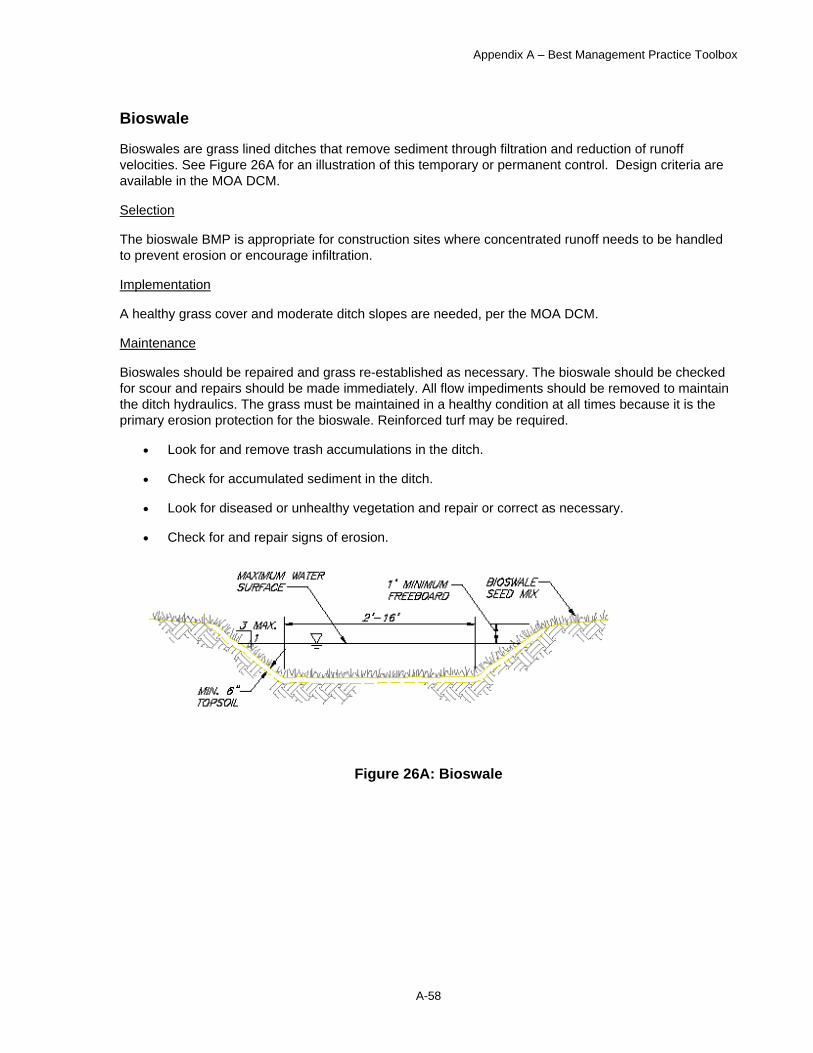
Appendix A – Best Management Practice Toolbox
A-58
Bioswale
Bioswales are grass lined ditches that remove sediment through filtration and reduction of runoff velocities. See Figure 26A for an illustration of this temporary or permanent control. Design criteria are available in the MOA DCM.
Selection
The bioswale BMP is appropriate for construction sites where concentrated runoff needs to be handled to prevent erosion or encourage infiltration.
Implementation
A healthy grass cover and moderate ditch slopes are needed, per the MOA DCM.
Maintenance
Bioswales should be repaired and grass re-established as necessary. The bioswale should be checked for scour and repairs should be made immediately. All flow impediments should be removed to maintain the ditch hydraulics. The grass must be maintained in a healthy condition at all times because it is the primary erosion protection for the bioswale. Reinforced turf may be required.
• Look for and remove trash accumulations in the ditch.
• Check for accumulated sediment in the ditch.
• Look for diseased or unhealthy vegetation and repair or correct as necessary.
• Check for and repair signs of erosion.
Figure 26A: Bioswale
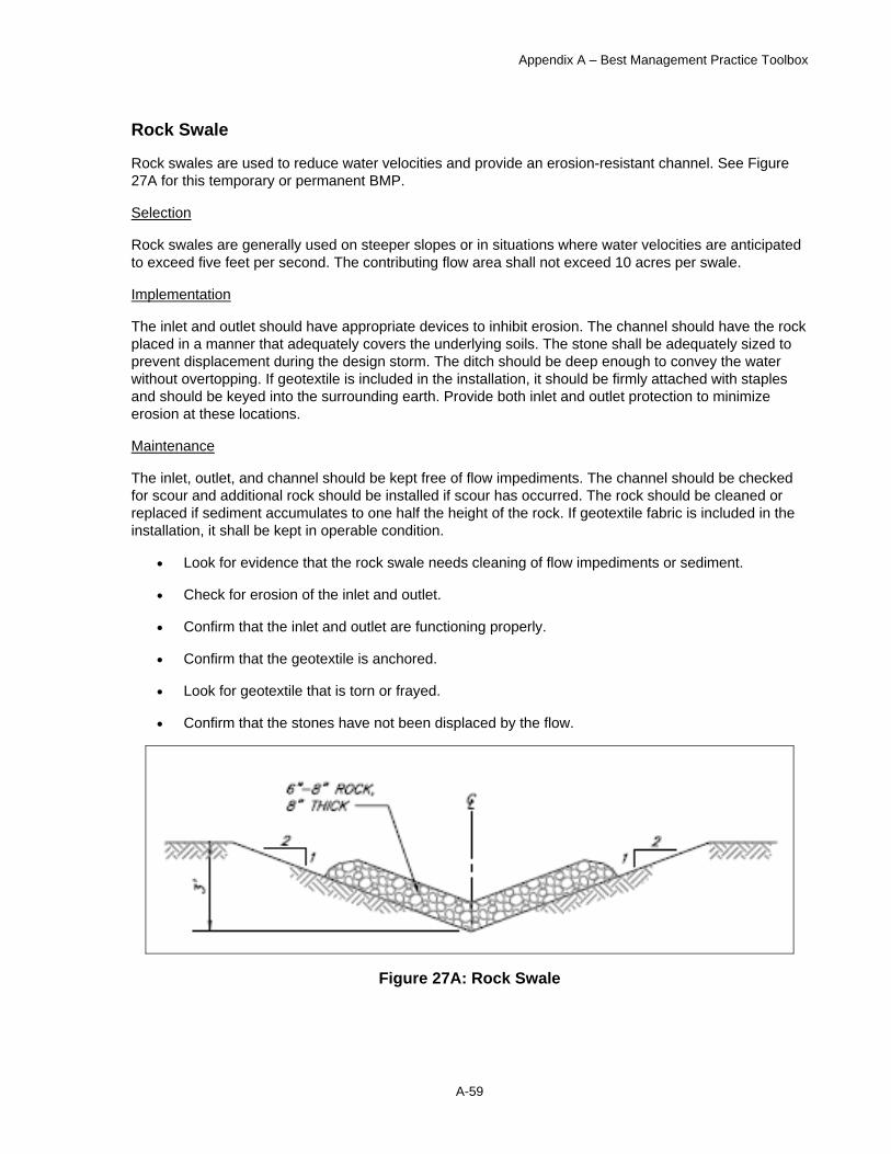
Appendix A – Best Management Practice Toolbox
A-59
Rock Swale
Rock swales are used to reduce water velocities and provide an erosion-resistant channel. See Figure 27A for this temporary or permanent BMP.
Selection
Rock swales are generally used on steeper slopes or in situations where water velocities are anticipated to exceed five feet per second. The contributing flow area shall not exceed 10 acres per swale.
Implementation
The inlet and outlet should have appropriate devices to inhibit erosion. The channel should have the rock placed in a manner that adequately covers the underlying soils. The stone shall be adequately sized to prevent displacement during the design storm. The ditch should be deep enough to convey the water without overtopping. If geotextile is included in the installation, it should be firmly attached with staples and should be keyed into the surrounding earth. Provide both inlet and outlet protection to minimize erosion at these locations.
Maintenance
The inlet, outlet, and channel should be kept free of flow impediments. The channel should be checked for scour and additional rock should be installed if scour has occurred. The rock should be cleaned or replaced if sediment accumulates to one half the height of the rock. If geotextile fabric is included in the installation, it shall be kept in operable condition.
• Look for evidence that the rock swale needs cleaning of flow impediments or sediment.
• Check for erosion of the inlet and outlet.
• Confirm that the inlet and outlet are functioning properly.
• Confirm that the geotextile is anchored.
• Look for geotextile that is torn or frayed.
• Confirm that the stones have not been displaced by the flow.
Figure 27A: Rock Swale
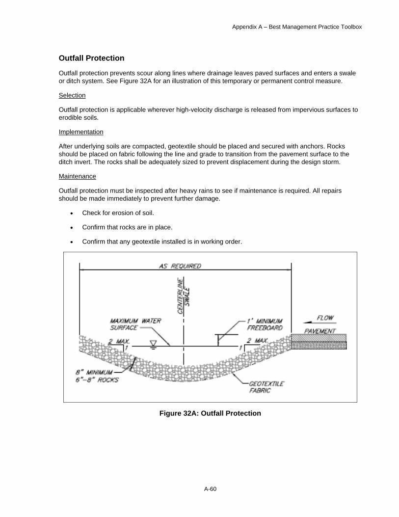
Appendix A – Best Management Practice Toolbox
A-60
Outfall Protection
Outfall protection prevents scour along lines where drainage leaves paved surfaces and enters a swale or ditch system. See Figure 32A for an illustration of this temporary or permanent control measure.
Selection
Outfall protection is applicable wherever high-velocity discharge is released from impervious surfaces to erodible soils.
Implementation
After underlying soils are compacted, geotextile should be placed and secured with anchors. Rocks should be placed on fabric following the line and grade to transition from the pavement surface to the ditch invert. The rocks shall be adequately sized to prevent displacement during the design storm.
Maintenance
Outfall protection must be inspected after heavy rains to see if maintenance is required. All repairs should be made immediately to prevent further damage.
• Check for erosion of soil.
• Confirm that rocks are in place.
• Confirm that any geotextile installed is in working order.
Figure 32A: Outfall Protection
Appendix A – Best Management Practice Toolbox
A-61
Existing Wetlands
An alternative to constructed wetlands, detention basins or sedimentation basins is to discharge storm water into existing wetlands. The MOA has developed planning level guidance in the document Anchorage Storm Water Treatment in Wetlands: 2002 Guidance. It is available on the WMS web page. Discharge of storm water, following treatment for removal of sediment and floatables, can function to rehabilitate wetlands that have been dried out due to urbanization.
Selection
This BMP is an attractive option when longer hydraulic residence times are necessary for pollutant removal and wetlands with adequate capacity are available.
Implementation • Install pretreatment to remove sediment. • Use flow dissipators to reduce channelization.
Maintenance
Existing wetlands normally do not need maintenance other than cleaning of accumulated debris and trash. These systems are typically self-cleaning.
• Make sure the wetland is free of trash, debris, and litter. • Make sure the pretreatment facility and outlet structures are operating properly. • Look for damaged or unhealthy aquatic plants that need replacement. Repair damaged
vegetation. Determine the causes, such as chlorides, excessive flow, or other factors, and mitigate them.

Appendix A – Best Management Practice Toolbox
A-62
Constructed Wetlands
Properly designed constructed wetlands can decrease the frequency and severity of flooding while improving water quality by providing decentralized controls, infiltration, and advanced treatment of storm water flows. Constructed wetlands are typically a permanent BMP.
Selection
Once established, constructed wetlands work best when there are available lands and a constant base flow to sustain the wetland. This BMP is an attractive option when longer hydraulic residence times are necessary for pollutant removal.
Implementation
The design and construction of wetlands is a significant undertaking that involves an adequate understanding of hydrology, landscape architecture, geotechnical engineering, groundwater science, and chemistry. Because of these requirements, a team of professionals is needed to properly simulate natural wetlands for storm water treatment.
Maintenance
Constructed wetlands normally do not need maintenance other than cleaning of accumulated debris and trash. These systems are typically self-cleaning.
• Make sure the wetland is free of trash, debris, and litter. • Make sure the inlet and outlet structures are operating properly. • Check for beaver and muskrat dams. • Look for damaged or unhealthy aquatic plants that need replacement.
Appendix A – Best Management Practice Toolbox
A-63
Preservation of Natural Drainage Systems
Preservation of natural drainage systems is a permanent procedural BMP that can significantly reduce stream bank erosion.
Selection
Preserving the natural drainage system works on any site that has existing drainage courses on or adjacent to the site. Natural channels reach a steady state in which sediment transport and deposition are balanced. Generally minimal increases in flow rates or duration can be accommodated in the natural system without upsetting the natural balance. However, major increases in flow are best accommodated by using alternative disposal methods.
Implementation
To use a natural drainage system, a thorough downstream analysis must be undertaken to ensure adverse affects do not occur to the system. Flow attenuation or energy dissipation devices may be needed at the discharge point. An erosion-resistant connection of the flow path between the new storm drainage system and the natural drainage system is necessary.
Maintenance
The beauty of using a natural drainage system is that it normally does not need maintenance other than cleaning of accumulated debris and trash. However, structural damage caused by storm events must be repaired as soon as possible to prevent further erosion of the stream bank.
• Look for erosion, undercutting, and channel instability. • Make sure the drainage path is free of trash, debris, and litter.

Appendix A – Best Management Practice Toolbox
A-64
Preservation of Natural Vegetation and Buffer Zones
A buffer zone is an undisturbed area of natural vegetation or other established plantings that will reduce soil erosion that is a result of runoff from uphill and reduce runoff velocity and capture sediment by providing a living filter. Natural vegetation should be preserved wherever practicable, but definitely on steep slopes and adjacent to perennial and intermittent drainages system inlets, water courses, swales, creeks, lakes, and wetlands.
Selection
Preserving natural vegetation is principally a component of the project site planning; however, preservation requires special attention during construction. Construction equipment can cause plant injury both above and below the ground. Damage results from scarring and cutting of roots and with compaction of soil.
Preserving natural vegetation can be part of scheduling and project phasing.
Implementation • See the Flagging and Fencing BMP for specific implementation requirements. • Retain a minimum of 50-foot wide vegetation buffer zones on each side of wetlands, creeks,
lakes, drainage systems, or other waterway, with increases subject to other onsite sensitive conditions, existing vegetative conditions, and erosion hazard potential. Where the slope is less than 4:1, the buffer may be reduced to 25 feet wide.
• Uphill of the are where vegetation is to be preserved, implant erosion and sediment control measures prior to clearing or other land disturbing activities.
• Avoid disturbing the ground at least as far out as a tree’s dripline. • Minimize raising or lowering the natural ground level. Since most tree and shrub plant roots are
n the upper foot of the soil, cuts and fills of only 2 to 3 inches can cause serious injury. To protect roots, terrace the immediate area around the plant to be saved.
Maintenance • Inspect the area frequently to ensure that flagging remains in place, that no disturbance has
occurred to the preserved vegetation, and that uphill control measures prevent concentrated runoff from entering the preserved area.
• If tree roots have been exposed or injured, recover or reseal them..
Appendix A – Best Management Practice Toolbox
A-65
LID: Reduced-Lot-Grading
During the grading portion of the development process, the land is generally sloped away from each home in an effort to move storm water runoff away from the foundation. Typically this slope is 2%. This slope is necessary to protect the foundation of a structure. However, this slope is often extended from the foundation all the way to the property boundaries. The effect is that storm water is not given an ample opportunity to infiltrate into the soil. The Reduced Lot Grading approach uses the 2% grade from the edge of the building to a distance of 20 feet in order to protect the foundation. The remaining lot area is sloped to drain away from the home at lesser grades ranging from 0.5% to 1.5%. This grading scheme will still direct storm water away from the foundation, but will also slow runoff and encourage infiltration.
Selection
New residential development on relatively flat land within the MOA is well suited for the application of reduced-lot-grading.
Implementation
Reduced-lot-grading is only applicable in areas that are relatively flat prior to development. Reduced-lot-grading is not effective if the soil on a site has been compacted due to the use of heavy equipment. It is best to keep the use of heavy equipment limited to paved surfaces. If compaction cannot be avoided, tilling or scarification of the soil to a depth of 12 to 24 inches prior to laying sod will restore the infiltration capacity of the compacted soil.
Maintenance
Reduced lot grading requires no long-term maintenance.

Appendix A – Best Management Practice Toolbox
A-66
LID: Reinforced-Turf-Driveways
Reinforced-turf-driveways (also called turf pavers) retain the weight bearing capacity necessary for a driveway but allow infiltration and plant growth, thus reducing the amount of impervious surface in the new development. The structures consist of modular paving blocks, or cast-in-place concrete grids, and are commonly referred to as “turf pavers.” Rather than be planted with turf, the voids in turf pavers can alternately be filled with sand or small gravel to provide the infiltration benefit and reduce the amount of maintenance required to keep healthy turf. There are several turf pavers available on the commercial market.
Selection
Urban and suburban driveways make excellent candidates for the use of turf pavers. The pavers can make up the entire driveway or only be placed in light use areas within the driveway, such as the area of the driveway straddled by automobiles entering and exiting.
Implementation
The usefulness of turf pavers is limited to areas where soils are permeable. Subbase depth for turf pavers depends on application and existing soils. For driveway application, a subbase of 8 to 12 inches is recommended. Manufacturers of turf pavers generally provide recommendations for subbase depth with their products. Turf pavers should be installed per the manufacturer’s specifications. Once installed, the voids in the turf pavers can be prepared for seeding.
Maintenance
Turf pavers require maintenance similar to lawn maintenance. Care must be taken in winter months not to damage plant life or the pavers during snow removal.
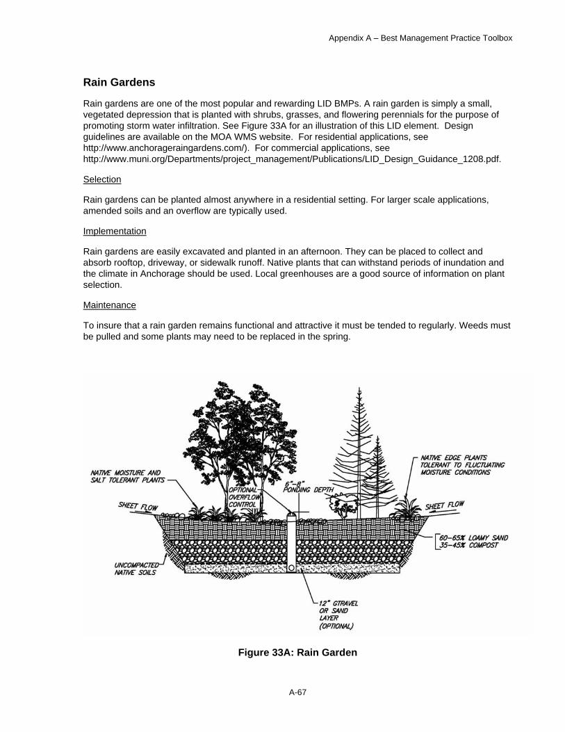
Appendix A – Best Management Practice Toolbox
A-67
Rain Gardens
Rain gardens are one of the most popular and rewarding LID BMPs. A rain garden is simply a small, vegetated depression that is planted with shrubs, grasses, and flowering perennials for the purpose of promoting storm water infiltration. See Figure 33A for an illustration of this LID element. Design guidelines are available on the MOA WMS website. For residential applications, see http://www.anchorageraingardens.com/). For commercial applications, see http://www.muni.org/Departments/project_management/Publications/LID_Design_Guidance_1208.pdf.
Selection
Rain gardens can be planted almost anywhere in a residential setting. For larger scale applications, amended soils and an overflow are typically used.
Implementation
Rain gardens are easily excavated and planted in an afternoon. They can be placed to collect and absorb rooftop, driveway, or sidewalk runoff. Native plants that can withstand periods of inundation and the climate in Anchorage should be used. Local greenhouses are a good source of information on plant selection.
Maintenance
To insure that a rain garden remains functional and attractive it must be tended to regularly. Weeds must be pulled and some plants may need to be replaced in the spring.
Figure 33A: Rain Garden

Appendix A – Best Management Practice Toolbox
A-68
Minimum Disturbance/Minimum Maintenance and Cluster Development:
Only those areas essential for completing construction activities should be cleared, and other areas should remain undisturbed. Avoid disturbing vegetation on steep slopes or other critical areas. Landscapes that demand significant amounts of chemical treatment should be avoided; thereby minimizing nonpoint source impacts associated with the application of fertilizers, pesticides, and herbicides that result from a new land development.
Appendix A – Best Management Practice Toolbox
A-69
Parking Lot Management Snow from streets and parking facilities contains many pollutants, with trash being the most visible of these materials. However, unseen pollutants from vehicles such as lead, zinc, copper, and petroleum products may also be present. In addition, the snow contains sand and salt used on streets and parking lots during the winter. Chloride levels in runoff rise sharply during periods of melting and taper off after a few weeks of warm weather. Because chloride and other pollutants can be present at high levels during breakup, the discharges from snow storage facilities and parking lot snow piles have a high potential to impact local water quality. Below are some general guidelines for storing and managing snow on parking lots and general parking lot maintenance. See also • The Anchorage Parking Lots: 2002 Best Management Practices Guidance
[http://wms.geonorth.com/library/Documents/Reports/BMP_Guidance/02_Pkglot_doc.pdf] provides design and maintenance information to reduce impacts of snowmelt runoff, and control pollutants from sand and deicers used for traction and ice control.
• Private Snow Disposal Sites (On-Site Snow Storage Only) [http://wms.geonorth.com/library/Documents/Reports/BMP_Guidance/PrivtSnoBMPs.pdf] provides information for management of on-site snow storage areas associated with parking lots.
Selection • Avoid placing snow piles on slopes where runoff will be difficult to control. • Never pile snow on, in to, or next to lakes, streams, or wells. • If possible, pile snow on a grassy surface.
Implementation • Place snow at a low point on site allowing the meltwater to pond in order to keep runoff
contained and easier to control. • Stack snow high in a single pile rather than in multiple piles around the site. The snow will melt
more slowly and allow storm drains to drain properly. • Use large or coarse grained material for sanding, since it is less likely to be transported off site. • If salting is necessary, use magnesium chloride instead of sodium chloride. Magnesium chloride
is better for the environment and is less abrasive to pavement. • If using salt, apply it lightly just before it snows or after plowing.
Maintenance • Before breakup, check that erosion problems will not occur when runoff begins. • As the snow pile melts, remove garbage that becomes exposed. • Sweeping
− Sweeping equipment, such as vacuum trucks, must be equipped with an effective baghouse or other filtering device.
− Mechanical devices without filtering equipment may be used only when wet sweeping methods are effectively employed.
− The use of leaf blowers and other similar equipment for sweeping is prohibited. − Manual broom sweeping is allowed − At a minimum, sweep once before May 15 or as snowmelt conditions permit to remove
winter sand and once between August 15 and October 15, with the last sweep as close to the first snowfall as can be predicted. This last sweep will reduce the amount of sediment available for runoff in the following spring breakup. More frequent sweeping, including a second pass following breakup (before May 15) and another before the August rains (between June 15 and August 15) are recommended for lots that have high usage or high particulate buildup.
− Control dust and particulate matter to comply with MOA fugitive emissions standards (AMC 15.35.090).
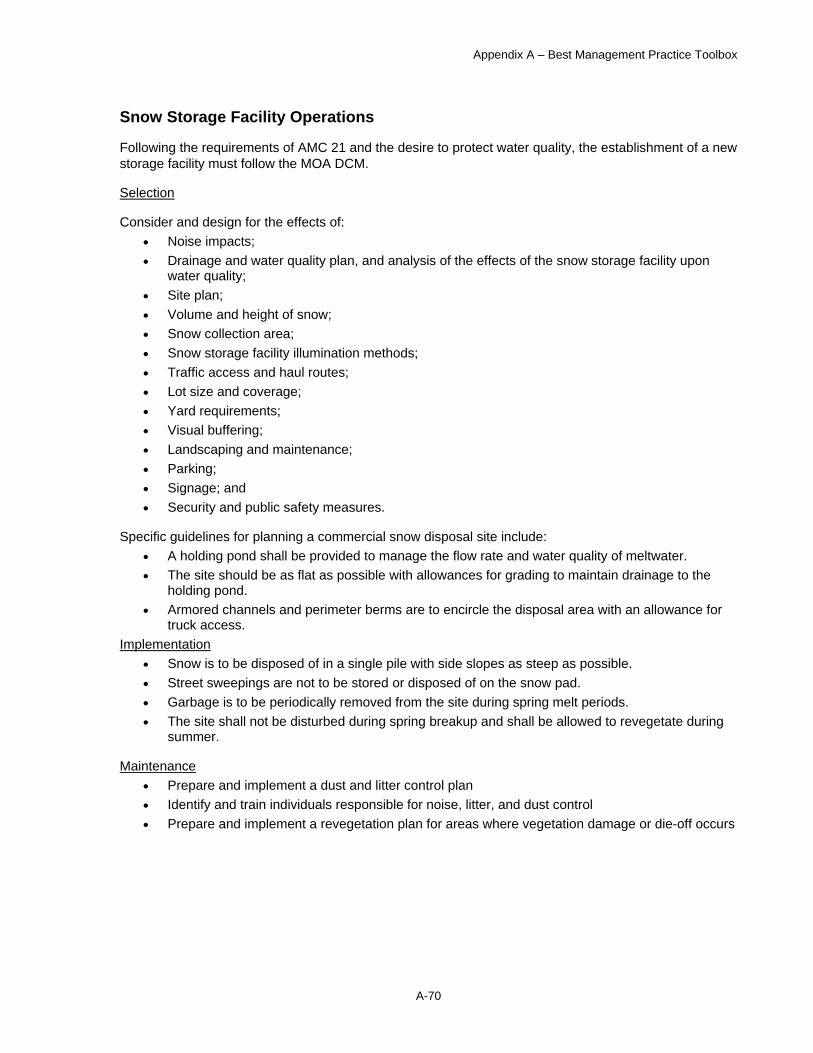
Appendix A – Best Management Practice Toolbox
A-70
Snow Storage Facility Operations
Following the requirements of AMC 21 and the desire to protect water quality, the establishment of a new storage facility must follow the MOA DCM.
Selection
Consider and design for the effects of: • Noise impacts; • Drainage and water quality plan, and analysis of the effects of the snow storage facility upon
water quality; • Site plan; • Volume and height of snow; • Snow collection area; • Snow storage facility illumination methods; • Traffic access and haul routes; • Lot size and coverage; • Yard requirements; • Visual buffering; • Landscaping and maintenance; • Parking; • Signage; and • Security and public safety measures.
Specific guidelines for planning a commercial snow disposal site include: • A holding pond shall be provided to manage the flow rate and water quality of meltwater. • The site should be as flat as possible with allowances for grading to maintain drainage to the
holding pond. • Armored channels and perimeter berms are to encircle the disposal area with an allowance for
truck access. Implementation
• Snow is to be disposed of in a single pile with side slopes as steep as possible. • Street sweepings are not to be stored or disposed of on the snow pad. • Garbage is to be periodically removed from the site during spring melt periods. • The site shall not be disturbed during spring breakup and shall be allowed to revegetate during
summer.
Maintenance • Prepare and implement a dust and litter control plan • Identify and train individuals responsible for noise, litter, and dust control • Prepare and implement a revegetation plan for areas where vegetation damage or die-off occurs

Appendix A – Best Management Practice Toolbox
A-71
Vehicle and Equipment Washing
Commercial car washes have interior wash water recirculation systems and are connected to the sanitary sewer system. Most facilities have exterior wash water collection systems as well. These systems are designed to reduce the amount of oil and grease, suspended solids, heavy metals, soluble organics, soaps, and detergents that are exposed to storm water. Conversely, non-commercial or uncontrolled car and equipment washing activities direct wash water, along with the associated pollutants, to the ground, then to the storm sewer system, and eventually to surface waters. Vehicles, construction equipment, aircraft, vessels, restaurant equipment, carpet cleaning equipment, industrial equipment, and large buildings may be cleaned with the following proper measures in place to protect the environment from contaminated storm water discharges.
• In order to keep storm water separated from pollutant sources, washing activities should ideally occur in an enclosure and drain to a sump or the sanitary sewer, or should occur in a building that drains to a sanitary sewer. Contaminated wash water must be routed to a sanitary sewer (which requires permission from AWWU), temporarily stored before being properly disposed of, or recycled with no discharge to the ground, a storm drain, or surface water.
• To conduct uncovered outside washing operations, a designated paved wash area that has containment must be provided to prevent storm water from running through the site or the fugitive discharge of wash water. The area must convey the wash water to a sanitary sewer or sump for collection and disposal.
• Phosphate-free biodegradable detergents should be used whenever possible. • At non-commercial car washes where it is not possible to discharge the wash water to a sanitary
sewer, a temporary plug or sump can be used at the storm drain to collect wash water for off-site disposal; a vegetative buffer can be used to infiltrate wash water; the washing could occur within a portable spill containment liner; or the vehicles can be rinsed without soaps or detergents of any kind.
• The wash water from building washing operations should be collected for treatment or routed to a sanitary sewer system if it contains oils, soaps, or detergents. Clean wash waters are allowed to drain into soils that have sufficient infiltrative capacity.
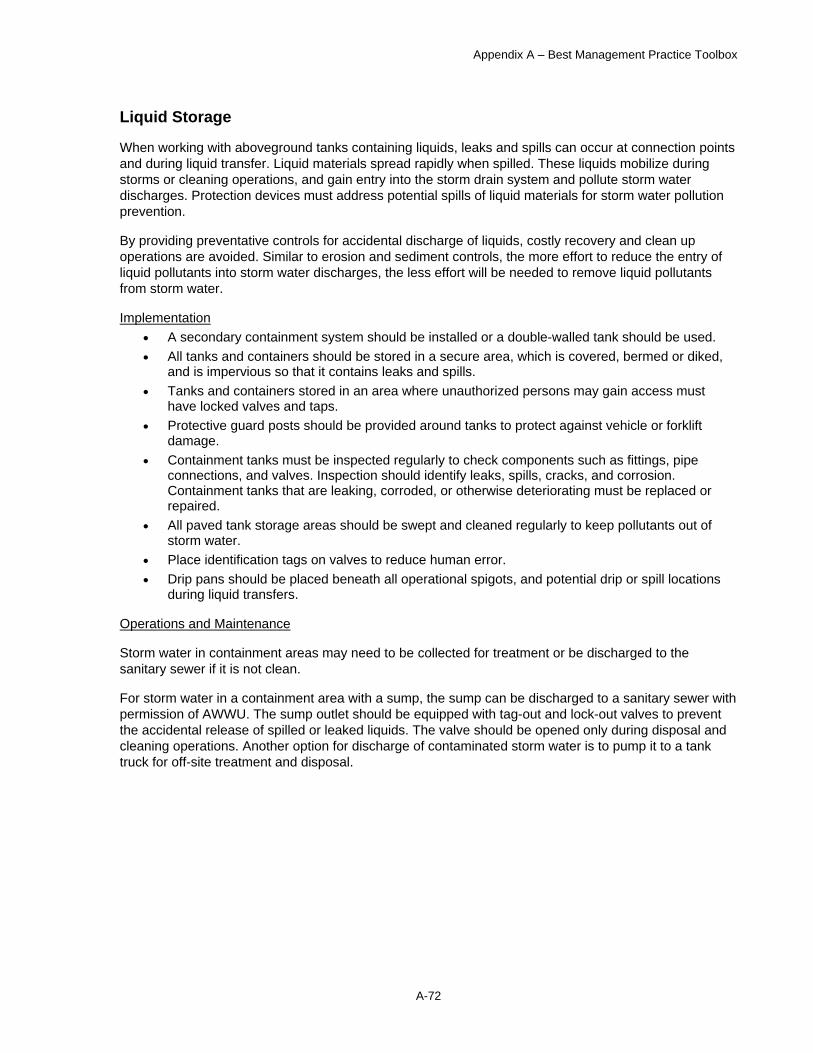
Appendix A – Best Management Practice Toolbox
A-72
Liquid Storage
When working with aboveground tanks containing liquids, leaks and spills can occur at connection points and during liquid transfer. Liquid materials spread rapidly when spilled. These liquids mobilize during storms or cleaning operations, and gain entry into the storm drain system and pollute storm water discharges. Protection devices must address potential spills of liquid materials for storm water pollution prevention.
By providing preventative controls for accidental discharge of liquids, costly recovery and clean up operations are avoided. Similar to erosion and sediment controls, the more effort to reduce the entry of liquid pollutants into storm water discharges, the less effort will be needed to remove liquid pollutants from storm water.
Implementation • A secondary containment system should be installed or a double-walled tank should be used. • All tanks and containers should be stored in a secure area, which is covered, bermed or diked,
and is impervious so that it contains leaks and spills. • Tanks and containers stored in an area where unauthorized persons may gain access must
have locked valves and taps. • Protective guard posts should be provided around tanks to protect against vehicle or forklift
damage. • Containment tanks must be inspected regularly to check components such as fittings, pipe
connections, and valves. Inspection should identify leaks, spills, cracks, and corrosion. Containment tanks that are leaking, corroded, or otherwise deteriorating must be replaced or repaired.
• All paved tank storage areas should be swept and cleaned regularly to keep pollutants out of storm water.
• Place identification tags on valves to reduce human error. • Drip pans should be placed beneath all operational spigots, and potential drip or spill locations
during liquid transfers.
Operations and Maintenance
Storm water in containment areas may need to be collected for treatment or be discharged to the sanitary sewer if it is not clean.
For storm water in a containment area with a sump, the sump can be discharged to a sanitary sewer with permission of AWWU. The sump outlet should be equipped with tag-out and lock-out valves to prevent the accidental release of spilled or leaked liquids. The valve should be opened only during disposal and cleaning operations. Another option for discharge of contaminated storm water is to pump it to a tank truck for off-site treatment and disposal.
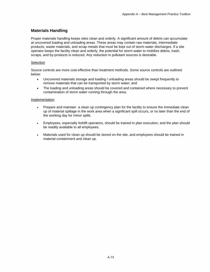
Appendix A – Best Management Practice Toolbox
A-73
Materials Handling
Proper materials handling keeps sites clean and orderly. A significant amount of debris can accumulate at uncovered loading and unloading areas. These areas may contain raw materials, intermediate products, waste materials, and scrap metals that must be kept out of storm water discharges. If a site operator keeps the facility clean and orderly, the potential for storm water to mobilize debris, trash, scraps, and by-products is reduced. Any reduction in pollutant sources is desirable.
Selection
Source controls are more cost-effective than treatment methods. Some source controls are outlined below:
• Uncovered materials storage and loading / unloading areas should be swept frequently to remove materials that can be transported by storm water; and
• The loading and unloading areas should be covered and contained where necessary to prevent contamination of storm water running through the area.
Implementation
• Prepare and maintain a clean up contingency plan for the facility to ensure the immediate clean up of material spillage in the work area when a significant spill occurs, or no later than the end of the working day for minor spills.
• Employees, especially forklift operators, should be trained in plan execution, and the plan should be readily available to all employees.
• Materials used for clean up should be stored on the site, and employees should be trained in material containment and clean up.

Appendix A – Best Management Practice Toolbox
A-74

Appendix B
MOA Handout AG.21 Stormwater Treatment Plan Review