APPENDIX 10G Geological and Foundation Design Criteria
60
APPENDIX 10G Geological and Foundation Design Criteria
Transcript of APPENDIX 10G Geological and Foundation Design Criteria

APPENDIX 10G
Geological and Foundation Design Criteria
APPENDIX 10G
Geologic and Foundation Design Criteria
10G1 Introduction This appendix includes the results of a recent subsurface investigation, and geotechnical assessment conducted by CHJ Incorporated (2005) for the Sun Valley Energy Project (SVEP) to support the Application for Certification (AFC). The geotechnical investigation report is included as an attachment to this appendix.
This appendix contains a description of the site conditions, and preliminary foundation-related subsurface conditions. Soil related hazards addressed include soil liquefaction, hydrocompaction (or collapsible soils), and expansive soils. Preliminary foundation and earthwork considerations are based on general published information available for the project area including recent geotechnical investigations for the property, and established geotechnical engineering practices. During the preparation of the Design Build Specification, a detailed geotechnical investigation will be conducted to address the subsurface soil conditions in order to develop site-specific and detailed design conditions.
Information contained in this appendix reflects the codes, standards, criteria and practices generally used in the design and construction of site and foundation engineering systems for the facility. More specific project information will be developed during execution of the project to support detailed design, engineering, material procurement, and construction specifications.
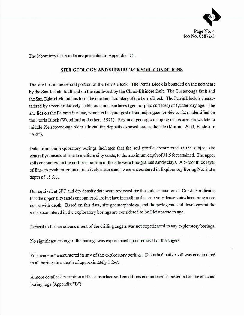
10G2 Site Conditions The SVEP project site is located near Romoland in unincorporated Riverside County on an approximately 20-acre parcel. The site is relatively flat and lies within the Perris Valley in the northern part of the Peninsular Ranges physiographic province at an elevation of approximately 1500 feet above mean sea level. The site is underlain by Quaternary alluvial sediments and older mostly marine sediments.
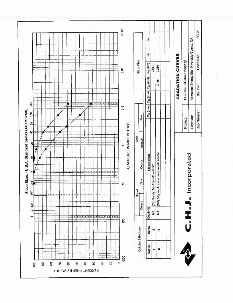
A site-specific geotechnical investigation was performed in August 2005 at the project site by CHJ, Incorporated. The scope of the study included an evaluation of geotechnical data to develop recommendations for site-specific grading, foundation design, and mitigation of geotechnical constraints. A copy of the geotechnical report is included as an attachment to this Appendix.
10G3 Site Subsurface Conditions 10.G3.1 Stratigraphy Generalized stratigraphy is discussed in Section 8.4, Geologic Hazards and Resources.
E092005018SAC/333716SV/052920006 (SVEP APP_10G_AD.DOC) 10G-1

APPENDIX 10G: GEOLOGIC AND FOUNDATION DESIGN CRITERIA COUNTY ADMINSTRATIVE DRAFT
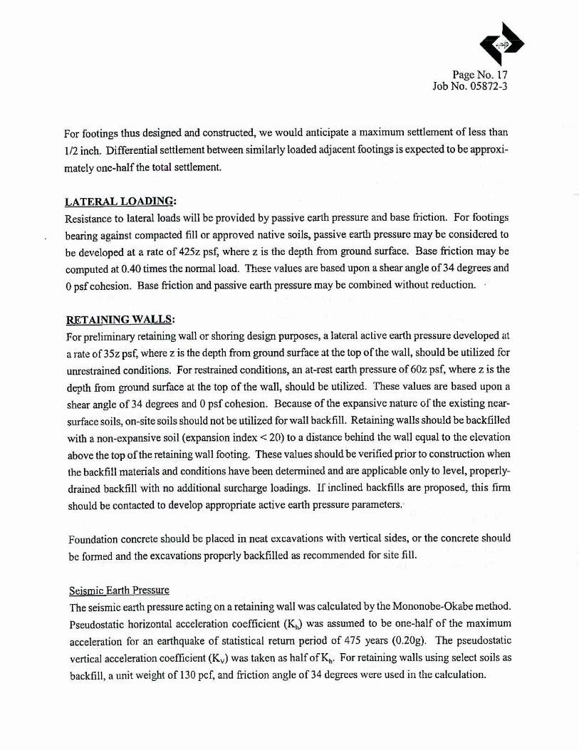
10G3.2 Seismicity/Ground Shaking The project area has experienced seismic activity with strong ground motion during past earthquakes and it is likely that strong earthquakes causing seismic shaking will occur in this area in the future. The site is located in Seismic Zone 4, according to the California Building Code. According to the site-specific geotechnical study conducted for the SVEP site, the estimated peak horizontal ground acceleration with a 10 percent probability of exceedance in 50 years is 0.41g (CJH, 2005). A description of the local geology and the relative location of major geologic faults in the area is presented in Section 8.4, Geologic Hazards and Resources.
10G3.3 Ground Rupture Ground rupture is caused when an earthquake ruptures the ground surface. Since no known faults exist at the project site, the likelihood of ground rupture at the SVEP site is low.
10G3.4 Groundwater The historic depth to groundwater at the project site is approximately 60 to 80 feet.
10G4 Assessment of Soil-Related Hazards 10G4.1 Liquefaction During strong earthquakes, loose, saturated, cohesionless soils can experience a temporary loss of shear strength and act as a fluid. This phenomenon is known as liquefaction. Liquefaction is dependent on depth to water, grain size distribution, relative density of the soils, degree of saturation, and intensity and duration of the earthquake. The potential hazard associated with liquefaction is seismically induced settlement. Soil liquefaction can lead to foundation bearing failures and excessive settlements when:
• • •
The design ground acceleration is high The water level is relatively shallow Low SPT blow counts are measured in granular deposits (suggesting low soil density)
The historic depth to groundwater at the project site is approximately 60 to 80 feet, and the soil types and the soil types generally consist of dense to medium dense clay, silt, and sand units not considered to be susceptible to liquefaction. Based site-specific soil testing, CHJ Incorporated (2005) determined the potential for liquefaction on site to be negligible.
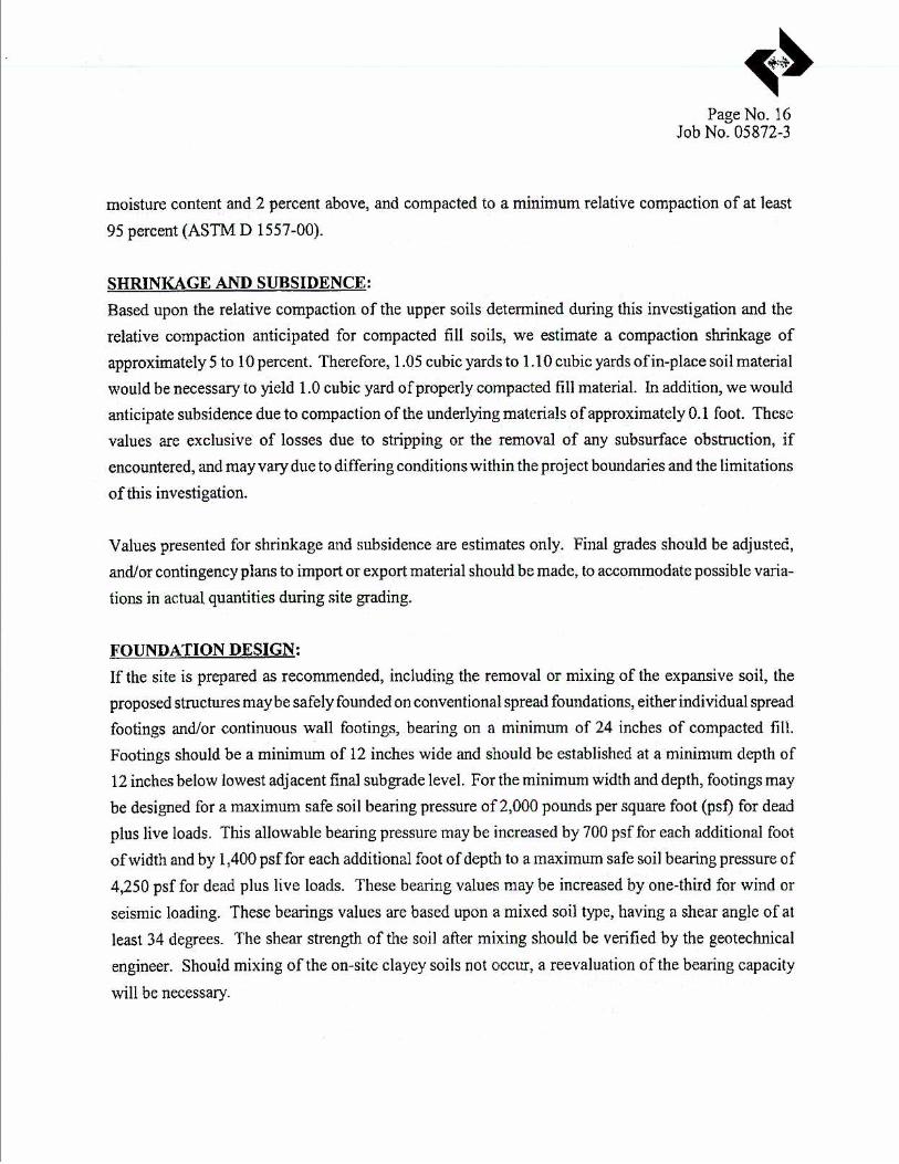
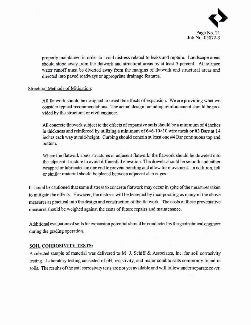
10G4.2 Expansive Soils Expansive soils shrink and swell with wetting and drying. The shrink-swell capacity of expansive soils can result in differential movement beneath foundations. Expansive soils shrink and swell with wetting and drying. Soil present at the site predominately consists of sandy loam derived from granitic materials. The sandy loam exhibits a low shrink-swell potential (USDA, 1971). An expansion potential index test was conducted on site specific soils and the results showed that a “low” to borderline “medium” potential for expansion is present (CHJ, Incorporated, 2005). Based on this potential, foundation design criteria contain provisions to include the potential for expansive soils at the site (see discussion, below). Expansive soils are further discussed in Section 8.11, Soils and Agriculture.
10G-2 E092005018SAC/333716SV/052920006 (SVEP APP_10G_AD.DOC)

COUNTY ADMINSTRATIVE DRAFT APPENDIX 10G: GEOLOGIC AND FOUNDATION DESIGN CRITERIA
10G4.3 Collapsible Soils Soil collapse (hydrocompaction) is a phenomenon that results in relatively rapid settlement of soil deposits due to addition of water. This generally occurs in soils having a loose particle structure cemented together with soluble minerals or with small quantities of clay. Water infiltration into such soils can break down the interparticle cementation, resulting in collapse of the soil structure. Collapsible soils are usually identified with index tests, such as dry density and liquid limit, and consolidation tests where soil collapse potential is measured after inundation under load.
Based on the available data, the potential for significant soil collapse at the site is expected to be low (CHJ Incorporated, 2005).
10G5 Preliminary Foundation Considerations 10G5.1 General Foundation Design Criteria For satisfactory performance, the foundation of any structure must satisfy two independent design criteria. First, it must have an acceptable factor of safety against bearing failure in the foundation soils under maximum design load. Second, settlements during the life of the structure must not be of a magnitude that will cause structural damage, endanger piping connections or impair the operational efficiency of the facility. Selection of the foundation type to satisfy these criteria depends on the nature and magnitude of dead and live loads, the base area of the structure and the settlement tolerances. Where more than one foundation type satisfies these criteria, then cost, scheduling, material availability and local practice will probably influence or determine the final selection of the type of foundation.
An evaluation of the information collected for the AFC indicates that no adverse foundation-related subsurface and ground water conditions would be encountered that would preclude the construction and operation of the proposed structures. The site can be considered suitable for development of the proposed structures in consideration of the geotechnical investigation to support of the engineering design, and using the information to address the preliminary foundation and earthwork considerations discussed in this appendix.
10G5.2 Spread Foundations Based on the findings of the geotechnical report (CHJ Incorporated, 2005), attached, the power plant facility would be supported on conventional spread foundations, either individual spread footings and/or continuous wall footings. Site preparation should include the removal or mixing of the expansive soils.
10G5.3 Corrosion Potential and Ground Aggressiveness Corrosivity tests will be conducted to determine whether the site soils to be non-corrosive or corrosive for buried steel based on the chloride content and pH values.
E092005018SAC/333716SV/052920006 (SVEP APP_10G_AD.DOC) 10G-3

APPENDIX 10G: GEOLOGIC AND FOUNDATION DESIGN CRITERIA COUNTY ADMINSTRATIVE DRAFT
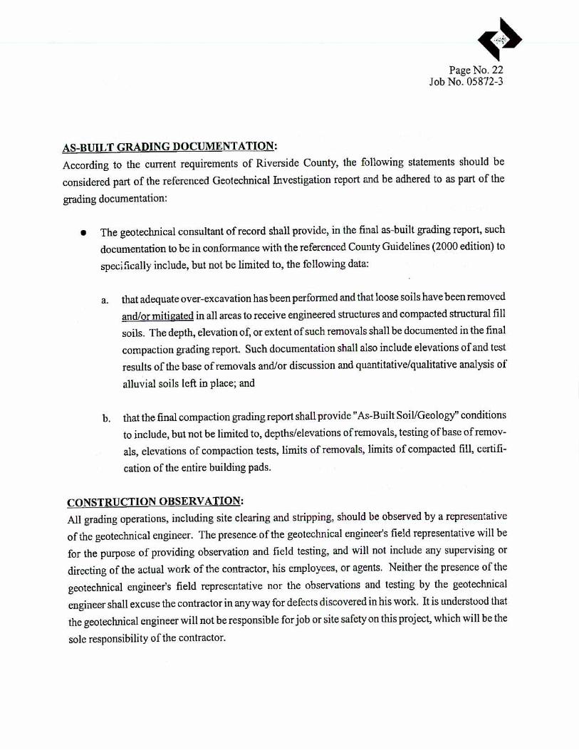
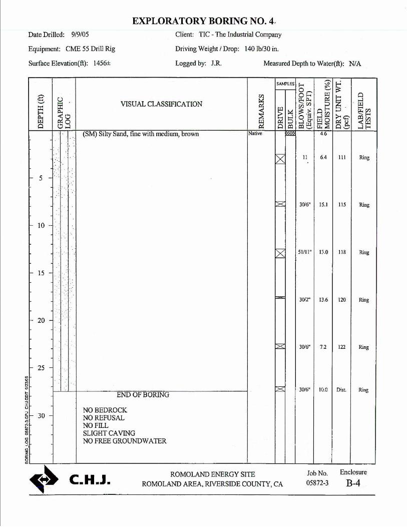
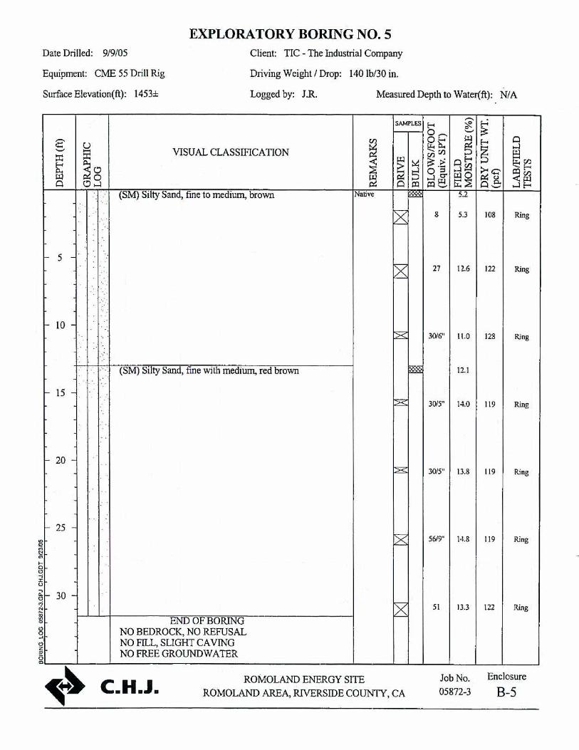
10G6 Preliminary Earthwork Considerations 10G6.1 Site Preparation and Grading Site grading may include (1) removal of existing deleterious materials and (2) fill to bring the site to a final grade. The geotechnical report (CHJ Incorporated, 2005) indicates that native soils were encountered at depths up to 31.5 feet at seven borings at the site. The report recommends the subexcavation of at least the top 36 inches of soil at the site to search for undocumented fill and the subsequent removal of deleterious materials before grading and compaction. The remaining material may be reused as compacted fill. The site fill work should be performed as detailed below. All soil surfaces to receive fill should be proof rolled with a heavy vibratory roller or a fully loaded dump truck to detect soft areas.
10G6.2 Temporary Excavations It is anticipated that confined temporary excavations at the site will be required during construction to remove undocumented fill or loose disturbed soils encountered during construction. All excavations should be sloped in accordance with OSHA requirements. All areas of the site should be subexcavated to a minimum depth of 36 inches below the existing surface to identify any undocumented fill or loose disturbed soils.
10G6.3 Backfill Requirements All fill material must be free of organic matter, debris or clay balls, with a maximum size not exceeding 6 inches. Structural fill must also be well graded and granular. Granular material with similar specifications can be used for pipe bedding, except that the maximum size should not exceed 0.5 inch.
Structural fill should be compacted to at least 95 percent of the maximum dry density as determined by ASTM D 1557 when used for raising the grade throughout the site, below footings or mats, or for rough grading. Fill placed behind retaining structures may be compacted to 90 percent of the maximum dry density as determined by ASTM D 1557. Initially, structural fill should be placed in lifts not exceeding 8 inches loose thickness. Thicker lifts may be used pursuant to approval based on results of field compaction performance. The moisture content of all compacted fill should fall within 3 percentage points of the optimum moisture content measured by ASTM D 1557, except compact the top 12 inches of subgrade to 95 percent of ASTM D 1557 maximum density.
Pipe bedding can be compacted in 12-inch lifts to 90 percent of the maximum dry density as determined by ASTM D 1557. Common fill to be placed in remote and/or unsurfaced areas may be compacted in 12-inch lifts to 85 percent of the maximum dry density as determined by ASTM D 1557.
10G7 Inspection and Monitoring A California-registered Geotechnical Engineer or Engineering Geologist will monitor geotechnical aspects of foundation construction and/or installation, and fill placement. At a minimum the Geotechnical Engineer/Engineering Geologist will monitor the following activities:
10G-4 E092005018SAC/333716SV/052920006 (SVEP APP_10G_AD.DOC)

COUNTY ADMINSTRATIVE DRAFT APPENDIX 10G: GEOLOGIC AND FOUNDATION DESIGN CRITERIA
•
•
•
•
•
All surfaces to receive fill should be inspected prior to fill placement to verify that no pockets of loose/soft or otherwise unsuitable material were left in place and that the subgrade is suitable for structural fill placement.
All fill placement operations should be monitored by an independent testing agency. Field compaction control testing should be performed regularly and in accordance with the applicable specification to be issued by the Geotechnical Engineer.
All sources of imported fill must be approved by the Geotechnical Engineer.
The Geotechnical Engineer must approve the foundation design.
Settlement monitoring of significant foundations and equipment is recommended on at least a quarterly basis during construction and the first year of operation, and then semi-annually for the next 2 years.
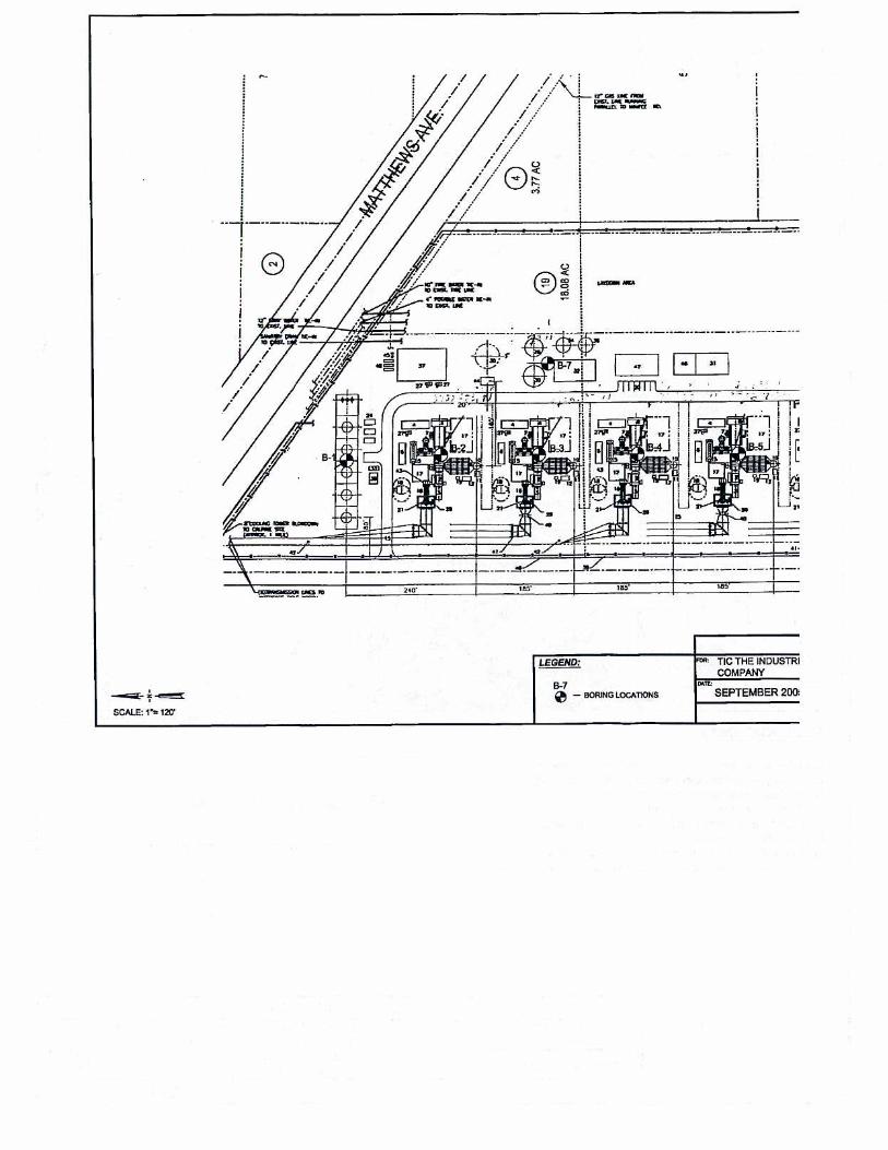
10G8 Site Design Criteria 10G8.1 General The project will be located near Romoland in unincorporated Riverside County on an approximately 20-acre parcel south of Matthews Road and 700 feet west of Menifee Road. The site would be accessible from Matthews Road.
10G8.2 Datum The site grade is at an elevation of approximately 1,500 feet above mean sea level. Final site grade elevation will be determined.
10G9 Foundation Design Criteria 10G9.1 General Reinforced concrete structures (spread footings, mats and continuous wall foundations) will be designed consistent with Appendix 10B.
Allowable soil bearing pressures for foundation design will be in accordance with this appendix.
10G9.2 Groundwater Pressures Hydrostatic pressures due to groundwater or temporary water loads will be considered.
10G9.3 Factors of Safety The factor of safety for structures, tanks and equipment supports with respect to overturning, sliding, and uplift due to wind and buoyancy will be as defined in Appendix 10B, Structural Engineering Design Criteria.
E092005018SAC/333716SV/052920006 (SVEP APP_10G_AD.DOC) 10G-5

APPENDIX 10G: GEOLOGIC AND FOUNDATION DESIGN CRITERIA COUNTY ADMINSTRATIVE DRAFT
10G9.4 Load Factors and Load Combinations For reinforced concrete structures and equipment supports, using the strength method, the load factors and load combinations will be in accordance with Appendix 10B, Structural Engineering Design Criteria.
10G9.4 Attachment 1, CHJ Incorporated. Geotechnical Investigation
10G10 References California Building Code. 2004.
C.H.J Incorporated, 2005 Geotechnical Investigation Romoland Energy Site Menifee Road and Matthews Road Romoland Area Riverside County, California Prepared For TIC – The Industrial Company.
10G-6 E092005018SAC/333716SV/052920006 (SVEP APP_10G_AD.DOC)
APPENDIX 10G
Attachment 1: Geotechnical Report