Appendix 1 practical guide to free energy devices by patrick j. kelly
469
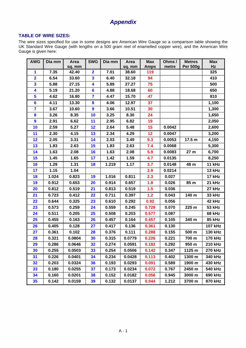
A - 1 Appendix TABLE OF WIRE SIZES: The wire sizes specified for use in some designs are American Wire Gauge so a comparison table showing the UK Standard Wire Gauge (with lengths on a 500 gram reel of enamelled copper wire), and the American Wire Gauge is given here: AWG Dia mm Area sq. mm SWG Dia mm Area sq. mm Max Amps Ohms / metre Metres Per 500g Max Hz 1 7.35 42.40 2 7.01 38.60 119 325 2 6.54 33.60 3 6.40 32.18 94 410 3 5.88 27.15 4 5.89 27.27 75 500 4 5.19 21.20 6 4.88 18.68 60 650 5 4.62 16.80 7 4.47 15.70 47 810 6 4.11 13.30 8 4.06 12.97 37 1,100 7 3.67 10.60 9 3.66 10.51 30 1,300 8 3.26 8.35 10 3.25 8.30 24 1,650 9 2.91 6.62 11 2.95 6.82 19 2,050 10 2.59 5.27 12 2.64 5.48 15 0.0042 2,600 11 2.30 4.15 13 2.34 4.29 12 0.0047 3,200 12 2.05 3.31 14 2.03 3.49 9.3 0.0053 17.5 m 4,150 13 1.83 2.63 15 1.83 2.63 7.4 0.0068 5,300 14 1.63 2.08 16 1.63 2.08 5.9 0.0083 27 m 6,700 15 1.45 1.65 17 1.42 1.59 4.7 0.0135 8,250 16 1.29 1.31 18 1.219 1.17 3.7 0.0148 48 m 11 kHz 17 1.15 1.04 2.9 0.0214 13 kHz 18 1.024 0.823 19 1.016 0.811 2.3 0.027 17 kHz 19 0.912 0.653 20 0.914 0.657 1.8 0.026 85 m 21 kHz 20 0.812 0.519 21 0.813 0.519 1.5 0.036 27 kHz 21 0.723 0.412 22 0.711 0.397 1.2 0.043 140 m 33 kHz 22 0.644 0.325 23 0.610 0.292 0.92 0.056 42 kHz 23 0.573 0.259 24 0.559 0.245 0.729 0.070 225 m 53 kHz 24 0.511 0.205 25 0.508 0.203 0.577 0.087 68 kHz 25 0.455 0.163 26 0.457 0.164 0.457 0.105 340 m 85 kHz 26 0.405 0.128 27 0.417 0.136 0.361 0.130 107 kHz 27 0.361 0.102 28 0.376 0.111 0.288 0.155 500 m 130 kHz 28 0.321 0.0804 30 0.315 0.0779 0.226 0.221 700 m 170 kHz 29 0.286 0.0646 32 0.274 0.0591 0.182 0.292 950 m 210 kHz 30 0.255 0.0503 33 0.254 0.0506 0.142 0.347 1125 m 270 kHz 31 0.226 0.0401 34 0.234 0.0428 0.113 0.402 1300 m 340 kHz 32 0.203 0.0324 36 0.193 0.0293 0.091 0.589 1900 m 430 kHz 33 0.180 0.0255 37 0.173 0.0234 0.072 0.767 2450 m 540 kHz 34 0.160 0.0201 38 0.152 0.0182 0.056 0.945 3000 m 690 kHz 35 0.142 0.0159 39 0.132 0.0137 0.044 1.212 3700 m 870 kHz
-
Upload
vegasstreetprophet -
Category
Documents
-
view
51 -
download
0
description
Transcript of Appendix 1 practical guide to free energy devices by patrick j. kelly
A - 1
Appendix
TABLE OF WIRE SIZES: The wire sizes specified for use in some designs are American Wire Gauge so a comparison table showing the UK Standard Wire Gauge (with lengths on a 500 gram reel of enamelled copper wire), and the American Wire Gauge is given here:
AWG Dia mm Area sq. mm
SWG Dia mm Area sq. mm
Max Amps
Ohms / metre
Metres Per 500g
Max Hz
1 7.35 42.40 2 7.01 38.60 119 325 2 6.54 33.60 3 6.40 32.18 94 410 3 5.88 27.15 4 5.89 27.27 75 500 4 5.19 21.20 6 4.88 18.68 60 650 5 4.62 16.80 7 4.47 15.70 47 810 6 4.11 13.30 8 4.06 12.97 37 1,100 7 3.67 10.60 9 3.66 10.51 30 1,300 8 3.26 8.35 10 3.25 8.30 24 1,650 9 2.91 6.62 11 2.95 6.82 19 2,050
10 2.59 5.27 12 2.64 5.48 15 0.0042 2,600 11 2.30 4.15 13 2.34 4.29 12 0.0047 3,200 12 2.05 3.31 14 2.03 3.49 9.3 0.0053 17.5 m 4,150 13 1.83 2.63 15 1.83 2.63 7.4 0.0068 5,300 14 1.63 2.08 16 1.63 2.08 5.9 0.0083 27 m 6,700 15 1.45 1.65 17 1.42 1.59 4.7 0.0135 8,250 16 1.29 1.31 18 1.219 1.17 3.7 0.0148 48 m 11 kHz 17 1.15 1.04 2.9 0.0214 13 kHz 18 1.024 0.823 19 1.016 0.811 2.3 0.027 17 kHz 19 0.912 0.653 20 0.914 0.657 1.8 0.026 85 m 21 kHz 20 0.812 0.519 21 0.813 0.519 1.5 0.036 27 kHz 21 0.723 0.412 22 0.711 0.397 1.2 0.043 140 m 33 kHz 22 0.644 0.325 23 0.610 0.292 0.92 0.056 42 kHz 23 0.573 0.259 24 0.559 0.245 0.729 0.070 225 m 53 kHz 24 0.511 0.205 25 0.508 0.203 0.577 0.087 68 kHz 25 0.455 0.163 26 0.457 0.164 0.457 0.105 340 m 85 kHz 26 0.405 0.128 27 0.417 0.136 0.361 0.130 107 kHz 27 0.361 0.102 28 0.376 0.111 0.288 0.155 500 m 130 kHz 28 0.321 0.0804 30 0.315 0.0779 0.226 0.221 700 m 170 kHz 29 0.286 0.0646 32 0.274 0.0591 0.182 0.292 950 m 210 kHz 30 0.255 0.0503 33 0.254 0.0506 0.142 0.347 1125 m 270 kHz 31 0.226 0.0401 34 0.234 0.0428 0.113 0.402 1300 m 340 kHz 32 0.203 0.0324 36 0.193 0.0293 0.091 0.589 1900 m 430 kHz 33 0.180 0.0255 37 0.173 0.0234 0.072 0.767 2450 m 540 kHz 34 0.160 0.0201 38 0.152 0.0182 0.056 0.945 3000 m 690 kHz 35 0.142 0.0159 39 0.132 0.0137 0.044 1.212 3700 m 870 kHz
A - 2
FRANK FECERA: PERMANENT MAGNET MOTOR
Patent US 6,867,514 B2 15th March 2005 Inventor: Frank J. Fecera
PERMANENT MAGNET MOTOR This patent application shows the details of a permanent magnet motor. It should be noted that while in this text, Frank states that permanent magnets store a finite amount of magnetism, in actual fact, the magnet poles form a dipole which causes a continuous flow of energy drawn from the quantum foam of our universe, and that flow continues until such time as the dipole is destroyed. The energy which powers any permanent magnet motor comes directly from the zero-point energy field and not actually from the magnet itself. A piece of iron can be converted into a magnet by a single nanosecond magnetic pulse. It makes no sense that a pulse of that duration could provide months of continuous power from anything stored in the magnet itself, but it makes perfect sense if that brief pulse created a magnetic dipole which acts as a gateway for the inflow of zero-point energy from the environment. ABSTRACT A motor providing unidirectional rotational motive power is provided. The motor has a generally circular stator with a stator axis, an outer surface, and a circumferential line of demarcation at about a midpoint of the outer surface. The motor also includes one or more stator magnets attached to the outer surface of the stator. The stator magnets are arranged in a generally circular arrangement about the stator axis and generate a first magnetic field. An armature is attached to the stator so that it rotates with it, the armature having an axis parallel to the stator axis. One or more rotors, are spaced from the armature and coupled to it by an axle to allow each rotor to rotate around an axis, each rotor rotating in a plane generally aligned with the axis of the armature. Each rotor includes one or more rotor magnets, with each rotor magnet generating a second magnetic field. The second magnetic field generated by each rotor magnet interacts with the first magnetic field, to cause each rotor to rotate about the rotor axis. A linkage assembly drive connects each rotor to the stator to cause the armature to rotate about the armature axis thereby providing the unidirectional rotational motive power of the motor. BACKGROUND OF THE INVENTION This invention relates to dynamo electric motor structures and more particularly to rotary and linear permanent magnet motors. Conventional electric motors rely on the interaction of magnetic fields to produce a force which results in either rotary or linear motion. The magnetic fields in conventional electric motors providing rotary power, are generated by passing an externally provided electric current through conductors in either a stator (i.e. stationary portion of the motor), a rotor (i.e. rotary portion) or both the stator and the rotor. The rotary power of the motor arises from a rotating magnetic field which is created by commutating the electric current, either by a switching the current through different conductors, as in a direct current motor or by a polarity reversal of the electric current as in an alternating current motor. It is well known that a class of materials known as ferromagnetic materials are also capable of generating a magnetic field having once been energised. Ferromagnetic materials with high coercivity are known as permanent magnets. Permanent magnets are capable of storing a finite amount of energy and retaining the ability to generate a substantial magnetic field until the stored energy is depleted. There are electric motors which use permanent magnets in either the stator portion of the motor or the rotor portion of the motor. These motors achieve a small size for the amount of power delivered by the motor because the motors avoid having current carrying conductors to produce the magnetic field which is otherwise produced by the permanent magnets. However, these conventional permanent magnet motors still require a source of external power to produce a rotating magnetic field. There have also been developed permanent magnet motors which use permanent magnets for both the stator and the rotor. For example, U.S. Pat. No. 4,598,221 discloses a permanent magnet motor which relies on an external source of power to rotate the magnetic fields of a rotor by ninety degrees with respect to the interacting stator magnetic fields to eliminate the counterproductive magnetic repulsion and attraction between the rotor and the stator magnets. In another example, U.S. Pat. No. 4,882,509 discloses a permanent magnet motor which relies on an external source of power to position a shield which does not permit coupling between the rotor and the stator magnets at times when attraction or repulsion would drag down the strength of the motor. There are many instances where a motor action is required and no source of external power is available. Accordingly, a motor which relies solely on the energy stored in permanent magnets would be useful. BRIEF SUMMARY OF THE INVENTION
A - 3
Briefly stated, the present invention comprises a rotor for use in a permanent magnet motor and for providing motive power by rotation of the rotor about a rotor axis. The rotor comprises at least one first U-shaped magnet having a rear side and generating a first magnetic field. The rotation of the rotor about the rotor axis is caused by an interaction of a portion of the first magnetic field directly adjacent to the rear of the at least one U-shaped magnet with a stationary second magnetic field. Another aspect of the present invention comprises a rotor providing motive power by a rotation of the rotor about the rotor axis and by a translation of the rotor in a direction of the rotor axis. The rotor comprises: a first U-shaped magnet having a north pole, a south pole and a rear side, the first U-shaped magnet generating a first magnetic field; a second U-shaped magnet having a north pole and a south pole, the south pole of the second U-shaped magnet abutting the north pole of the first U-shaped magnet; and a third U-shaped magnet having a north pole and a south pole, the north pole of the third U-shaped magnet abutting the south pole of the first U-shaped magnet. A portion of the first magnetic field generated by the first U-shaped magnet directly adjacent to the rear of the first U-shaped magnet interacts with a stationary fourth magnetic field to cause the rotor to rotate. A second magnetic field generated by the north pole of the second U-shaped magnet and a third magnetic field generated by the south pole of the third U-shaped magnet interact with the fourth magnetic field to cause the rotor to translate in the direction of the rotor axis. A further aspect of the present invention comprises a rotor including a rotor axis, and a thruster axis in a plane of the rotor and intersecting the rotor axis. The rotor provides motive power by a rotation of the rotor about the rotor axis and by a translation of the rotor in a direction of the rotor axis. The rotor comprises: a first U-shaped magnet having a north pole and a south pole and a rear side, the north pole and the south pole being generally aligned with the thruster axis, the first U-shaped magnet generating a first magnetic field; a first thruster magnet having a direction of magnetisation generally aligned with the thruster magnet axis, the first thruster magnet being proximate to and spaced from the north pole of the first U-shaped magnet; and a second thruster magnet having a direction of magnetisation generally aligned with the thruster magnet axis, the second thruster magnet being near to and spaced from the south pole of the first U-shaped magnet, the first U-shaped magnet being interposed between the first and the second thruster magnets. A portion of the first magnetic field generated by the first U-shaped magnet directly adjacent to the rear side of the first U-shaped magnet interacts with a stationary fourth magnetic field to cause the rotor to rotate, a second magnetic field generated by the first thruster magnet and a third magnetic field generated by the second thruster magnet respectively interact with a stationary fifth magnetic field to cause the rotor to translate in the direction of the rotor axis. Another aspect of the present invention comprises a rotor providing motive power by rotation of the rotor about a rotor axis and translation of the rotor in the direction of the rotor axis. The rotor has at least one rotor magnet generating a first magnetic field, the first magnetic field being generated by the rotor magnet interacting with at least one stationary U-shaped magnet, the U-shaped magnet having a rear side and generating a second magnetic field. The rotational and translational motive power of the rotor is provided by an interaction of a portion of the second magnetic field directly adjacent to the rear of the U-shaped magnet with the first magnetic field. A further aspect of the present invention comprises a motor providing unidirectional rotational motive power. The motor includes a generally circular stator having a stator axis, an outer surface, and a circumferential line of demarcation at about a midpoint of the outer surface; at least one stator magnet attached to the outer surface of the stator, the at least one stator magnet being arranged in a generally circular arrangement about the stator axis and generating a first magnetic field; an armature attached to the stator for rotation with it; the armature having an axis parallel to the stator axis; at least one rotor, the rotor being spaced from the armature and coupled to it by an axle to allow rotation about an axis of the rotor, the rotor rotating in a plane generally aligned with the armature axis, the rotor, including at least one magnet generating a second magnetic field, where the second magnetic field generated by the rotor magnet interacts with the first magnetic field to cause the rotor to rotate about it’s axis; and a drive linkage assembly connecting the rotor to the stator to cause the armature to rotate about it’s axis as the rotor rotates about it’s axis, thereby providing the unidirectional rotational motive power of the motor. In another aspect, the present invention is directed to a motor providing unidirectional rotational motive power comprising: a generally circular stator having an axis, an outer surface, and a circumferential line of demarcation around the outer surface, the line of demarcation having a pre-determined direction around the stator axis and separating a first side of the outer surface and a second side of the outer surface, wherein at least one pair of stator magnets is attached to the outer surface generating a first magnetic field, the pair of magnets comprising a first stator magnet having a north pole and a south pole and a second stator magnet having a north pole and a south pole, the south pole of the first stator magnet being located on the first side of the outer surface and the north pole of the first stator magnet being closest to the line of demarcation, the north pole of the second stator magnet being located on the second side of the outer surface and the south pole of the second stator magnet being closest to the line of demarcation, wherein the at least one pair of stator magnets is spaced along the line of demarcation so that a first inter-magnet distance measured along the line of demarcation between the north pole of the first stator magnet and the south pole of the second stator magnet of an adjacent pair of the at least one pair of stator magnets is generally equal to a second inter-magnet distance measured along the line of
A - 4
demarcation between the south pole of the first stator magnet and the north pole of the second stator magnet; an armature attached to the stator, the armature having an axis parallel to the stator axis and attached to the stator for rotation therewith; and at least one rotor attached to the armature, the at least one rotor being spaced from the armature and coupled to it by an axle for rotation about an axis of the rotor, the rotor rotating in a plane generally aligned with the armature axis, the rotor comprising at least one rotor magnet, the rotor magnet generating a second magnetic field which interacts with the first magnetic field to cause the rotor to rotationally oscillate about the axis of the rotor and to generate a force in a direction of the rotor axis, thereby causing the armature to rotate in the pre-determined direction around the armature axis to provide the unidirectional rotational motive power of the motor. In a further aspect, the present invention is directed to a motor providing unidirectional linear motive power comprising: a linear stator having a generally curved cross-section and a longitudinal line of demarcation perpendicular to the cross-section extending on about a midpoint of a surface of the stator between a first end and a second end of the stator, the stator including at least one magnet arranged between the first end and the second end, the magnet having a direction of magnetisation at about a right angle to the line of demarcation and generating a first magnetic field, the magnitude of the first magnetic field being generally uniform along the line of demarcation except in a pre-determined number of null regions, wherein the first magnetic field is substantially zero a rail connected to the stator, the rail having a longitudinal axis generally parallel to the line of demarcation and a helical groove with a pre-determined pitch running around a periphery of the rail; at least one rotor having a rotor axis aligned with the axis of the rail, the rotor being connected to the rail so that the rotor is free to rotate about the axis of the rail and slide along the rail, the rotor including at least one U-shaped magnet having a rear side and generating a second magnetic field, where a portion of the second magnetic field directly adjacent to the rear of the U-shaped magnet interacts with the first magnetic field to cause the rotor to rotate about the axis of the rail; a bearing assembly connecting the rotor to the helical groove, the bearing assembly converting the rotary motion of the rotor about the axis of the rail to linear motion along the rail; and a cross-link connecting the bearing assembly of a first rotor to a second rotor, thereby adding together the linear motion along the rail of the first rotor and the second rotor to provide the unidirectional linear motive power. In yet another aspect, the present invention is directed to a motor providing unidirectional motive power comprising: a rail having a longitudinal axis and at least one helical groove having a pre-determined pitch running around a periphery of the rail; at least one first helical stator concentrically surrounding the rail, the first helical stator having the pre-determined pitch of the groove and a longitudinal axis generally parallel to the axis of the rail, at least one first stator magnet being attached to the first helical stator, the first stator magnet generating a first magnetic field; at least one rotor having an axis generally aligned with the axis of the rail, the rotor being connected to the rail so that the rotor is free to rotate about the axis of the rail and slide along the rail, the rotor comprising at least one rotor magnet generating a second magnetic field, the second magnetic field interacting with the first magnetic field generated by the first stator magnet to cause the rotor to rotate about the axis of the rail; and a bearing assembly connecting the rotor to the helical groove around the periphery of the rail, the bearing assembly converting the rotational motion of the rotor about the rail to unidirectional linear motion along the rail. A further aspect of the present invention is directed to a motor providing unidirectional motive force comprising: a rail having a longitudinal axis and a helical groove running around the rail, the groove having a predetermined pitch; at least one first helical stator comprising a plurality of discontinuous spaced apart first ribs, each first rib partially surrounding the rail at a generally uniform distance from the rail, the first helical stator having the pre-determined pitch of the groove and a longitudinal axis generally aligned with the rail, at least one first stator magnet being attached to each rib, each first stator magnet generating a first magnetic field; at least one rotor having an axis generally aligned with the axis of the rail, the rotor being connected to the rail so that the rotor is free to rotate about the axis of the rail and to slide along the rail, the rotor comprising at least one rotor magnet generating a second magnetic field, the second magnetic field interacting with the first magnetic field generated by the first stator magnet to cause the rotor to rotate about the axis of the rail; and a bearing assembly connecting the rotor to the helical groove around the rail, the bearing assembly converting the rotary motion of the rotor about the rail to linear motion along the rail. The present invention is further directed to a motor providing unidirectional motive power comprising: a rail having a longitudinal axis and a generally sinusoidal groove running around a periphery of the rail, the sinusoidal groove having a pre-determined period; at least one stator having a generally curved cross-section and a longitudinal line of demarcation perpendicular to the cross-section located at about a midpoint of a surface of the stator, the surface of the stator being disposed generally equidistant from and parallel to the axis of the rail; at least one stator magnet attached to the surface of the stator generating a first magnetic field, the stator magnet having a magnetisation which is displaced sinusoidally from the line of demarcation, the sinusoid having a pre-determined period and a pre-determined maximum amplitude and being divided into a plurality of alternating first and second sectors, with a boundary between the alternating first and second sectors occurring at the maximum amplitude of the sinusoid, the direction of magnetisation of the stator magnet being opposite in direction in the first and second segments; at least one rotor having an axis aligned with the axis of the rail, the rotor being connected to the rail so that the rotor is free to rotate about the axis of the rail and slide along the rail, the rotor including at least one U-

A - 5
shaped magnet having a rear side and generating a second magnetic field, the U-shaped magnet being positioned on the rotor so that the rear side of the U-shaped magnet is apposite to the first and the second segments of the stator as the rotor rotates about the rotor axis, wherein an interaction of a portion of the second magnetic field directly adjacent to the rear of the U-shaped magnet with the first magnetic field causes the rotor to rotationally oscillate about the axis of the rail; and a bearing assembly connecting the rotor to the sinusoidal groove around the rail, the bearing assembly converting the oscillatory motion of the rotor about the rail to unidirectional linear motion along the rail. The present invention is also directed to a motor providing unidirectional motive power comprising: a rail having a longitudinal axis and a helical groove running around a periphery of the rail, the helical groove having a pre-determined pitch; at least one stator having a generally having a longitudinal line of demarcation located at about a midpoint of a surface of the stator, the surface of the stator being disposed generally equidistant from and parallel to the axis of the rail; at least one stator magnet attached to the surface of the stator, the stator magnet having a direction of magnetisation which rotates about a magnetic axis parallel to the line of demarcation with a predetermined pitch, thereby generating a first magnetic field having a substantially uniform magnitude along the magnetic axis and rotates around the magnetic axis with the pre-determined pitch of the stator magnet rotation; at least one rotor having an axis aligned with the axis of the rail, the rotor being connected to the rail so that the rotor is free to rotate about the axis of the rail and slide along the rail, the rotor including at least one U-shaped magnet generating a second magnetic field, the U-shaped magnet being positioned on the rotor so that a portion of the second magnetic field directly adjacent to the rear side of the U-shaped magnet interacts with the first magnetic field of the stator magnet to cause the rotor to rotate about it’s axis; and a bearing assembly connecting the rotor to the helical groove, the bearing assembly converting the rotary motion of the rotor about the rail to unidirectional linear motion along the rail. BRIEF DESCRIPTION OF THE SEVERAL VIEWS OF THE DRAWINGS The foregoing summary, as well as the following detailed description of preferred embodiments of the invention, will be better understood when read in conjunction with the appended drawings. For the purpose of illustrating the invention, there are shown in the drawings embodiments which are presently preferred. It should be understood, however, that the invention is not limited to the precise arrangements and instrumentalities shown. In the drawings:
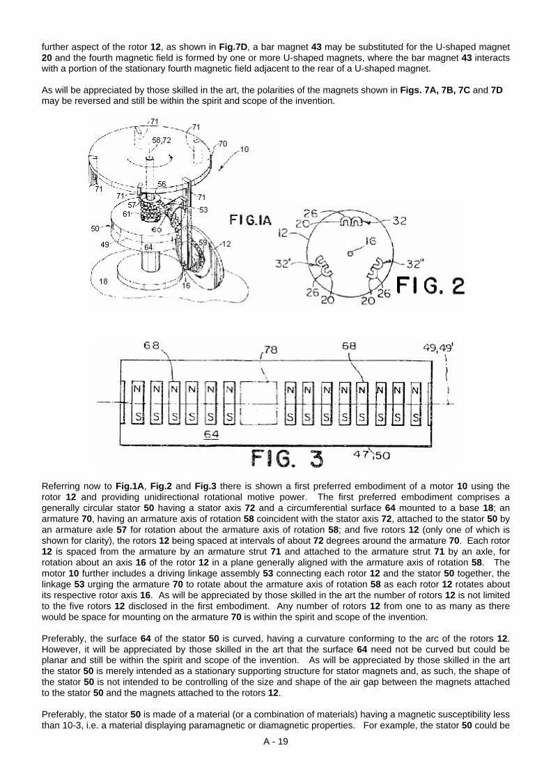
Fig.1A is a schematic perspective drawing of a first preferred embodiment of a motor providing unidirectional motive power;

A - 6
Fig.1B is a schematic perspective drawing of a second preferred embodiment of the motor;
Fig.1C is a schematic perspective drawing of a third preferred embodiment of the motor;

A - 7
Fig.2 is a schematic plan view of a rotor comprising three pair of U-shaped magnets;
Fig.3 is a schematic plan view of stator having a plurality of stator magnets generating a uniform magnetic field except in single null region, laid out flat for ease of illustration;
Fig.4 is an schematic plan view of a stator having a plurality of stator magnets which rotate about a magnetic axis, laid out flat for ease of illustration;
A - 8
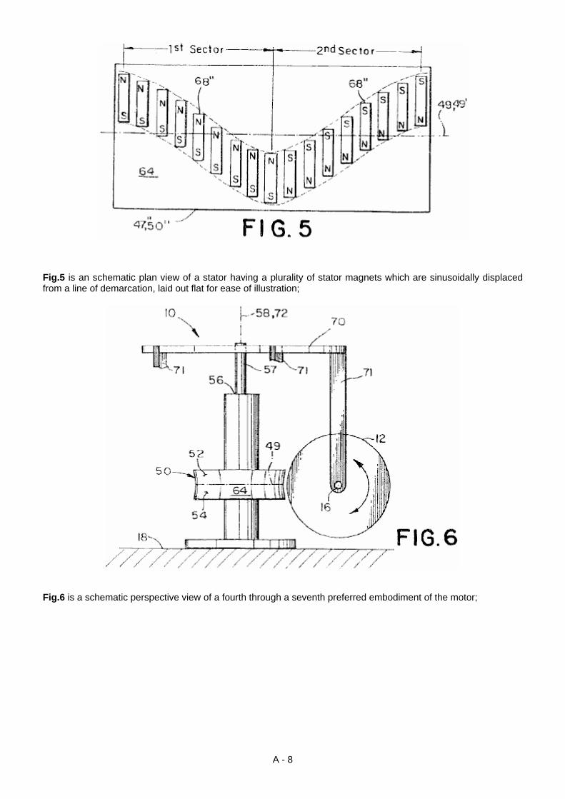
Fig.5 is an schematic plan view of a stator having a plurality of stator magnets which are sinusoidally displaced from a line of demarcation, laid out flat for ease of illustration;
Fig.6 is a schematic perspective view of a fourth through a seventh preferred embodiment of the motor;
A - 9
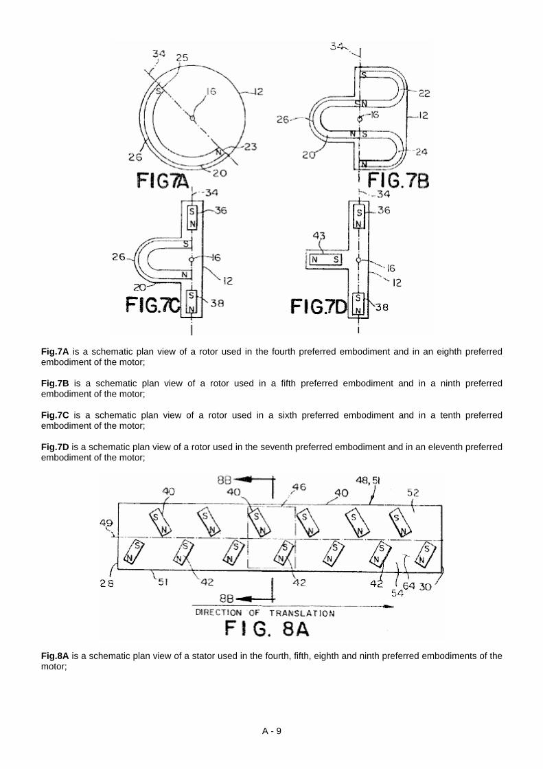
Fig.7A is a schematic plan view of a rotor used in the fourth preferred embodiment and in an eighth preferred embodiment of the motor; Fig.7B is a schematic plan view of a rotor used in a fifth preferred embodiment and in a ninth preferred embodiment of the motor; Fig.7C is a schematic plan view of a rotor used in a sixth preferred embodiment and in a tenth preferred embodiment of the motor; Fig.7D is a schematic plan view of a rotor used in the seventh preferred embodiment and in an eleventh preferred embodiment of the motor;
Fig.8A is a schematic plan view of a stator used in the fourth, fifth, eighth and ninth preferred embodiments of the motor;

A - 10
Fig.8B is a schematic sectional view of the stator shown in Fig.8A taken along the line 8B-8B;
Fig.8C is a schematic plan view of a stator used in the sixth and in the tenth preferred embodiments of the motor;
Fig.8D is a schematic elevational view of the stator shown in Fig.8C taken along the line 8D-8D shown with the rotor shown in Fig.7C; Fig.8E is a schematic elevational view of an alternative stator shown with the rotor shown in Fig.7D;
A - 11
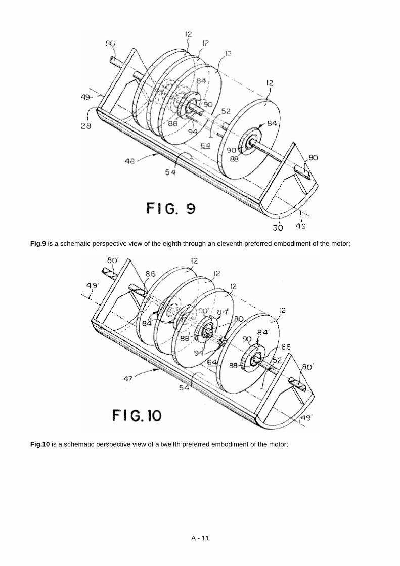
Fig.9 is a schematic perspective view of the eighth through an eleventh preferred embodiment of the motor;
Fig.10 is a schematic perspective view of a twelfth preferred embodiment of the motor;
A - 12
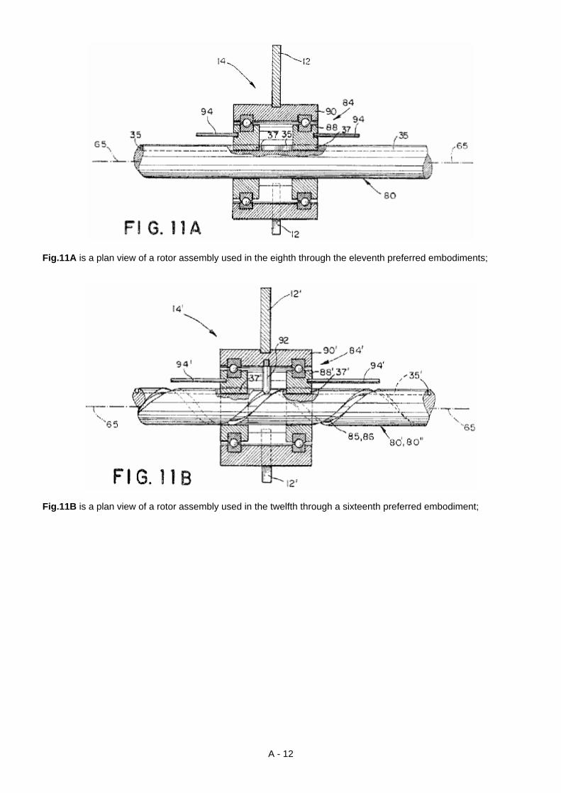
Fig.11A is a plan view of a rotor assembly used in the eighth through the eleventh preferred embodiments;
Fig.11B is a plan view of a rotor assembly used in the twelfth through a sixteenth preferred embodiment;
A - 13
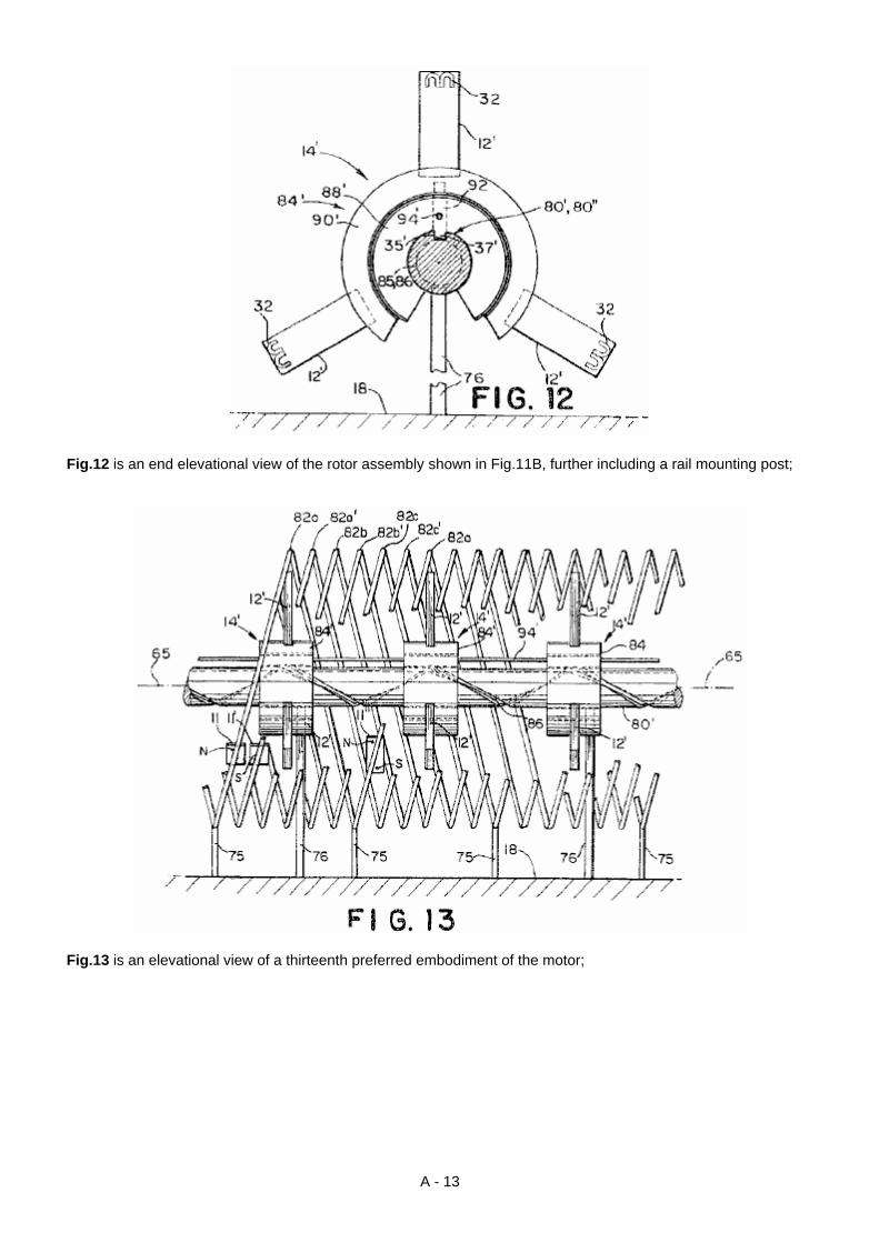
Fig.12 is an end elevational view of the rotor assembly shown in Fig.11B, further including a rail mounting post;
Fig.13 is an elevational view of a thirteenth preferred embodiment of the motor;
A - 14
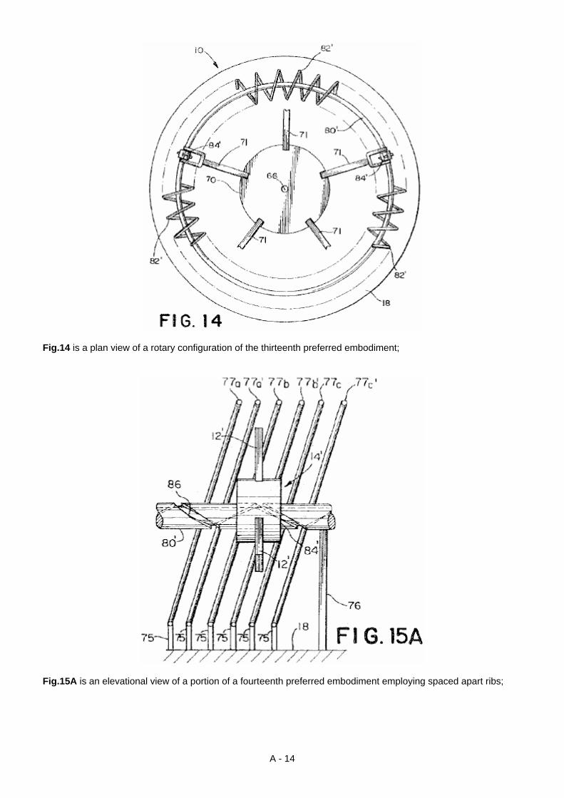
Fig.14 is a plan view of a rotary configuration of the thirteenth preferred embodiment;
Fig.15A is an elevational view of a portion of a fourteenth preferred embodiment employing spaced apart ribs;
A - 15
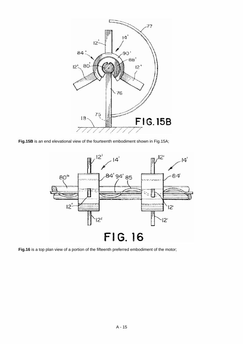
Fig.15B is an end elevational view of the fourteenth embodiment shown in Fig.15A;
Fig.16 is a top plan view of a portion of the fifteenth preferred embodiment of the motor;

A - 16
Fig.17 is an elevational end view of the fifteenth preferred embodiment shown in Fig.16;
Fig.18 is a top plan view of a portion of the sixteenth preferred embodiment of the motor; and

A - 17
Fig.19 is an elevational end view of the sixteenth preferred embodiment of the motor shown in Fig.18. DETAILED DESCRIPTION OF THE INVENTION It will be appreciated by those skilled in the art that changes could be made to the embodiments described above without departing from the broad inventive concept thereof. It is understood, therefore, that this invention is not limited to the particular embodiments disclosed, but it is intended to cover modifications within the spirit and scope of the present invention as defined by the appended claims. It should also be understood that the articles "a" and "the" used in the claims to define an element may refer to a single element or to a plurality of elements without a limit as to the number of elements. Past attempts to construct a working permanent magnet motor have met with difficulties because of the simultaneous attractive and repulsive characteristics of a permanent magnet. A principle has been discovered where, by engaging a magnetic field at the rear of one or more U-shaped magnets mounted on a rotor with a second stationary magnetic field, a torque is created that rotates the rotor about a rotational axis of the rotor. Further, by properly shaping the second magnetic field, the rotor may be caused to also translate in the direction of the rotor axis.

A - 18
Accordingly, using the aforementioned principle, and referring to Fig.7A, one aspect of the present invention is directed to a rotor 12 for use in a motor and which provides motive power by a rotation of the rotor 12 about a rotor axis 16 and by a translation of the rotor 12 in a direction of the rotor axis 16. In one aspect, the rotor 12 comprises a first U-shaped magnet 20 in which the U-shaped magnet 20 generates a first magnetic field. A rotation of the rotor 12 about the rotor axis 16 is caused by an interaction of a portion of the first magnetic field directly adjacent to a rear 26 of the U-shaped magnet 20 with a stationary second magnetic field. A translation of the rotor 12 in the direction of the rotor axis 16 is caused by an interaction of the first magnetic field adjacent to a north pole 23 and a south pole 25 of the U-shaped magnet 20 with the stationary second magnetic field. As will be appreciated by those skilled in the art, the design of the rotor 12 is not limited to a single U-shaped magnet 12. A plurality of U-shaped magnets 20, arranged around a periphery of the rotor 12 is within the spirit and scope of the invention. Another aspect of the present invention, shown in Fig.7B comprises a rotor 12 including a first U-shaped magnet having a north pole and a south pole generating a first magnetic field; a second U-shaped magnet 24 having a north pole and a south pole with the south pole of the second U-shaped magnet 24 abutting the north pole of the first U-shaped magnet 20; and a third U-shaped magnet 22 having a north pole and a south pole with the north pole of the third U-shaped magnet 22 abutting the south pole of the first U-shaped magnet 20. A portion of the first magnetic field generated by the first U-shaped magnet 20 directly adjacent to the rear 26 of the first U-shaped magnet 20 interacts with a stationary fourth magnetic field to cause the rotor 12 to rotate. A second magnetic field generated by the north pole of the second U-shaped magnet 24 and a third magnetic field generated by the south pole of the third U-shaped magnet 22 respectively interact with the fourth magnetic field to cause the rotor 12 to translate in the direction of the rotor axis 16. A further aspect of the present invention, shown in Fig.7C, comprises a first U-shaped magnet 20 having a north pole and a south pole generating a first magnetic field. The north pole and the south pole of the U-shaped magnet 20 are generally aligned with a thruster axis 34 which lies in the plane of the rotor 12 and intersects the rotor axis 16. A first thruster magnet 36 is located proximate to and spaced from the north pole of the first U-shaped magnet with a direction of magnetisation being generally aligned with the thruster magnet axis 34. A second thruster magnet 38 is located proximate to and spaced from the south pole of the first U-shaped magnet 20 with a direction of magnetisation also being generally aligned with the thruster magnet axis 34. A portion of the first magnetic field generated by the first U-shaped magnet 20 directly adjacent to the rear side 26 of the first U-shaped magnet 20 interacts with a stationary fourth magnetic field to cause the rotor 12 to rotate. A second magnetic field generated by both the north pole and the south pole of the first thruster magnet 36 and a third magnetic field generated by both the north pole and the south pole of the second thruster magnet 38 respectively interact with a fifth magnetic field to cause the rotor 12 to translate in the direction of the rotor axis 16. In one
A - 19
further aspect of the rotor 12, as shown in Fig.7D, a bar magnet 43 may be substituted for the U-shaped magnet 20 and the fourth magnetic field is formed by one or more U-shaped magnets, where the bar magnet 43 interacts with a portion of the stationary fourth magnetic field adjacent to the rear of a U-shaped magnet. As will be appreciated by those skilled in the art, the polarities of the magnets shown in Figs. 7A, 7B, 7C and 7D may be reversed and still be within the spirit and scope of the invention.
Referring now to Fig.1A, Fig.2 and Fig.3 there is shown a first preferred embodiment of a motor 10 using the rotor 12 and providing unidirectional rotational motive power. The first preferred embodiment comprises a generally circular stator 50 having a stator axis 72 and a circumferential surface 64 mounted to a base 18; an armature 70, having an armature axis of rotation 58 coincident with the stator axis 72, attached to the stator 50 by an armature axle 57 for rotation about the armature axis of rotation 58; and five rotors 12 (only one of which is shown for clarity), the rotors 12 being spaced at intervals of about 72 degrees around the armature 70. Each rotor 12 is spaced from the armature by an armature strut 71 and attached to the armature strut 71 by an axle, for rotation about an axis 16 of the rotor 12 in a plane generally aligned with the armature axis of rotation 58. The motor 10 further includes a driving linkage assembly 53 connecting each rotor 12 and the stator 50 together, the linkage 53 urging the armature 70 to rotate about the armature axis of rotation 58 as each rotor 12 rotates about its respective rotor axis 16. As will be appreciated by those skilled in the art the number of rotors 12 is not limited to the five rotors 12 disclosed in the first embodiment. Any number of rotors 12 from one to as many as there would be space for mounting on the armature 70 is within the spirit and scope of the invention. Preferably, the surface 64 of the stator 50 is curved, having a curvature conforming to the arc of the rotors 12. However, it will be appreciated by those skilled in the art that the surface 64 need not be curved but could be planar and still be within the spirit and scope of the invention. As will be appreciated by those skilled in the art the stator 50 is merely intended as a stationary supporting structure for stator magnets and, as such, the shape of the stator 50 is not intended to be controlling of the size and shape of the air gap between the magnets attached to the stator 50 and the magnets attached to the rotors 12. Preferably, the stator 50 is made of a material (or a combination of materials) having a magnetic susceptibility less than 10-3, i.e. a material displaying paramagnetic or diamagnetic properties. For example, the stator 50 could be
A - 20
made of a non-magnetic metal such as aluminium or brass. Also, the rotor 12 could be made of a natural material such as wood, glass, a polymeric material or a combination of any of the aforementioned materials within the spirit and scope of the invention. Further, it should be understood that the aforementioned materials are preferred for the stators and all other parts of the motor 10 that could significantly disrupt the magnetic interaction between the stator and the rotor of all of the disclosed preferred embodiments of the motor 10. In the first preferred embodiment, the surface 64 of the stator 50 includes a circumferential line of demarcation 49 at about a midpoint of the surface 64 formed by an intersection with the surface 64 of a plane perpendicular to the armature axis of rotation 58. As shown in Fig.3, the stator 50 includes a plurality of bar magnets 68 attached to the outer surface 64 along the line of demarcation 49, except in a single null region 78 where the magnitude of the first magnetic field is substantially reduced. The bar magnets 68 have a direction of magnetisation at about a right angle to the line of demarcation 49 thereby creating a first magnetic field adjacent to the outer surface 64, the magnitude and the direction of which is substantially uniform along the circumferential line of demarcation 49 around the axis 58 of the stator 50, except within the null region 78. As will be appreciated by those skilled in the art, the stator axis 72 need not be coincident with the armature axis of rotation 58. Accordingly, a stator 50 arranged around the armature axis 58 at any location at which the stator axis 72 is parallel to the armature axis 58 and the surface 64 of the stator 50 faces the periphery of the rotors 12 thereby providing for the interaction between the first magnetic field and the second magnetic field around the armature axis 58, is within the spirit and scope of the invention. Preferably, as further shown in Fig.3, the bar magnets are attached to the surface 64 of the stator 50 so that the direction of magnetisation of the bar magnets 68 are about perpendicular to a radial line of the rotor 12. However, the bar magnets 68 could also be attached to the surface 64 of the stator so that the direction of magnetisation of the bar magnets 68 is aligned with a radial line of the rotor 12. The bar magnets 68 are preferably abutting so as to form the substantially uniform first magnetic field. However, it is not necessary for the bar magnets 68 to abut one another. Further, it is not necessary to use a plurality of bar magnets 68 to form the first magnetic field. A single magnet producing a uniform first magnetic field in the region in which the first magnetic field interacts with the second magnetic field of the rotors 12 would provide the required first magnetic field. Also, the number of null regions 78 may be more than one, depending upon the desired speed of the motor, as explained below. Preferably, the stator magnets 68 are permanent magnets made of a neodymium-iron-boron material. However, as will be appreciated by those skilled in the art, any type of permanent magnet material displaying ferromagnetic properties could be used for the stator magnets 68. For instance, stator magnets 68 made of samarium cobalt, barium ferrite or AlNiCo are within the spirit and scope of the invention. It should be understood that these permanent magnet materials or their equivalents are preferred for the stator magnets and the rotor magnets of all of the disclosed preferred embodiments of the motor 10. Also, while the use of permanent magnets is preferred, the use of electro-magnets for some or all of the magnets is within the spirit and scope of the invention. As discussed above, the stator 50 may include a pre-determined number of null regions 78 on the surface of the stator 64. In the first preferred embodiment, the single null region 78 is formed by a shield of a ferromagnetic material, such as iron, placed adjacent to the surface 64. However, as those skilled in the art will appreciate, the null region 78 can also be formed by an absence of the bar magnets 68 in the region coinciding with the null region 78. The null region 78 of substantially reduced magnetic field magnitude may also be formed by an auxiliary magnetic field suitably generated by one or more permanent magnets or by one or more electromagnets powered by an electric current arranged so that the auxiliary magnetic field substantially cancels the first magnetic field in the null region 78. In the case of the electromagnets, the electric current may be turned off in synchronism with the rotation of the rotors 12 passing through the null region 78, in order to conserve power. Preferably, the first magnetic field is reduced to ten percent or less of the magnetic force outside of the null region. However, the motor 10 will operate with a reduction of only fifty percent. Accordingly, a motor 10 having a substantial reduction of the first magnetic field of fifty percent or less is within the spirit and scope of the invention.
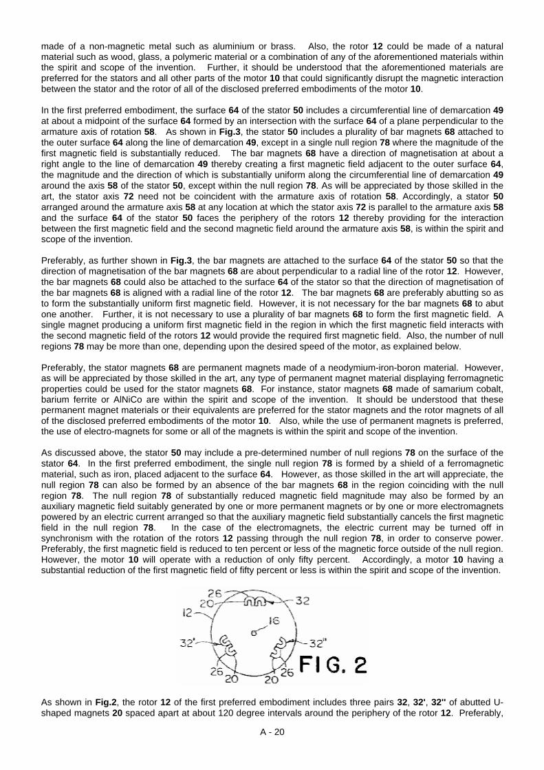
As shown in Fig.2, the rotor 12 of the first preferred embodiment includes three pairs 32, 32', 32'' of abutted U-shaped magnets 20 spaced apart at about 120 degree intervals around the periphery of the rotor 12. Preferably,
A - 21
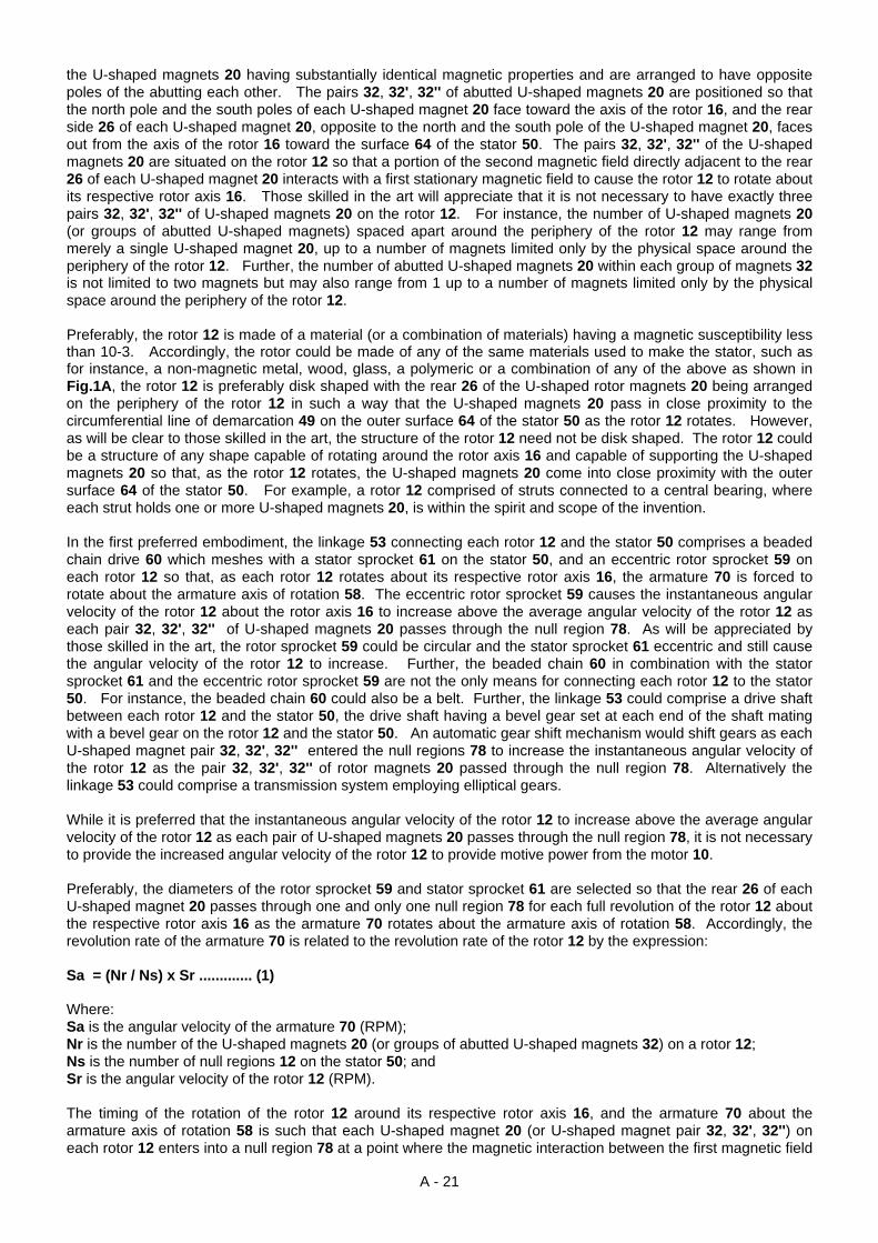
the U-shaped magnets 20 having substantially identical magnetic properties and are arranged to have opposite poles of the abutting each other. The pairs 32, 32', 32'' of abutted U-shaped magnets 20 are positioned so that the north pole and the south poles of each U-shaped magnet 20 face toward the axis of the rotor 16, and the rear side 26 of each U-shaped magnet 20, opposite to the north and the south pole of the U-shaped magnet 20, faces out from the axis of the rotor 16 toward the surface 64 of the stator 50. The pairs 32, 32', 32'' of the U-shaped magnets 20 are situated on the rotor 12 so that a portion of the second magnetic field directly adjacent to the rear 26 of each U-shaped magnet 20 interacts with a first stationary magnetic field to cause the rotor 12 to rotate about its respective rotor axis 16. Those skilled in the art will appreciate that it is not necessary to have exactly three pairs 32, 32', 32'' of U-shaped magnets 20 on the rotor 12. For instance, the number of U-shaped magnets 20 (or groups of abutted U-shaped magnets) spaced apart around the periphery of the rotor 12 may range from merely a single U-shaped magnet 20, up to a number of magnets limited only by the physical space around the periphery of the rotor 12. Further, the number of abutted U-shaped magnets 20 within each group of magnets 32 is not limited to two magnets but may also range from 1 up to a number of magnets limited only by the physical space around the periphery of the rotor 12. Preferably, the rotor 12 is made of a material (or a combination of materials) having a magnetic susceptibility less than 10-3. Accordingly, the rotor could be made of any of the same materials used to make the stator, such as for instance, a non-magnetic metal, wood, glass, a polymeric or a combination of any of the above as shown in Fig.1A, the rotor 12 is preferably disk shaped with the rear 26 of the U-shaped rotor magnets 20 being arranged on the periphery of the rotor 12 in such a way that the U-shaped magnets 20 pass in close proximity to the circumferential line of demarcation 49 on the outer surface 64 of the stator 50 as the rotor 12 rotates. However, as will be clear to those skilled in the art, the structure of the rotor 12 need not be disk shaped. The rotor 12 could be a structure of any shape capable of rotating around the rotor axis 16 and capable of supporting the U-shaped magnets 20 so that, as the rotor 12 rotates, the U-shaped magnets 20 come into close proximity with the outer surface 64 of the stator 50. For example, a rotor 12 comprised of struts connected to a central bearing, where each strut holds one or more U-shaped magnets 20, is within the spirit and scope of the invention. In the first preferred embodiment, the linkage 53 connecting each rotor 12 and the stator 50 comprises a beaded chain drive 60 which meshes with a stator sprocket 61 on the stator 50, and an eccentric rotor sprocket 59 on each rotor 12 so that, as each rotor 12 rotates about its respective rotor axis 16, the armature 70 is forced to rotate about the armature axis of rotation 58. The eccentric rotor sprocket 59 causes the instantaneous angular velocity of the rotor 12 about the rotor axis 16 to increase above the average angular velocity of the rotor 12 as each pair 32, 32', 32'' of U-shaped magnets 20 passes through the null region 78. As will be appreciated by those skilled in the art, the rotor sprocket 59 could be circular and the stator sprocket 61 eccentric and still cause the angular velocity of the rotor 12 to increase. Further, the beaded chain 60 in combination with the stator sprocket 61 and the eccentric rotor sprocket 59 are not the only means for connecting each rotor 12 to the stator 50. For instance, the beaded chain 60 could also be a belt. Further, the linkage 53 could comprise a drive shaft between each rotor 12 and the stator 50, the drive shaft having a bevel gear set at each end of the shaft mating with a bevel gear on the rotor 12 and the stator 50. An automatic gear shift mechanism would shift gears as each U-shaped magnet pair 32, 32', 32'' entered the null regions 78 to increase the instantaneous angular velocity of the rotor 12 as the pair 32, 32', 32'' of rotor magnets 20 passed through the null region 78. Alternatively the linkage 53 could comprise a transmission system employing elliptical gears. While it is preferred that the instantaneous angular velocity of the rotor 12 to increase above the average angular velocity of the rotor 12 as each pair of U-shaped magnets 20 passes through the null region 78, it is not necessary to provide the increased angular velocity of the rotor 12 to provide motive power from the motor 10. Preferably, the diameters of the rotor sprocket 59 and stator sprocket 61 are selected so that the rear 26 of each U-shaped magnet 20 passes through one and only one null region 78 for each full revolution of the rotor 12 about the respective rotor axis 16 as the armature 70 rotates about the armature axis of rotation 58. Accordingly, the revolution rate of the armature 70 is related to the revolution rate of the rotor 12 by the expression: Sa = (Nr / Ns) x Sr ............. (1) Where: Sa is the angular velocity of the armature 70 (RPM); Nr is the number of the U-shaped magnets 20 (or groups of abutted U-shaped magnets 32) on a rotor 12; Ns is the number of null regions 12 on the stator 50; and Sr is the angular velocity of the rotor 12 (RPM). The timing of the rotation of the rotor 12 around its respective rotor axis 16, and the armature 70 about the armature axis of rotation 58 is such that each U-shaped magnet 20 (or U-shaped magnet pair 32, 32', 32'') on each rotor 12 enters into a null region 78 at a point where the magnetic interaction between the first magnetic field
A - 22
and the second magnetic field is substantially reduced, thus providing a commutation of the second magnetic field. As each rotor 12 continues to rotate about the rotor axis 16 and the armature 70 rotates about the armature axis of rotation 58, the U-shaped magnet 20 traces a slanted path through the null region 78. As the U-shaped magnet emerges from the null region 78, the U-shaped magnet 20 encounters the strong first magnetic field, which urges the U-shaped magnet 20 to continue the rotation of the rotor 12 about the rotor axis 16. As previously discussed, the first preferred embodiment of the motor 10 comprises a single null region 78 and five rotors 12, each rotor 12 having three pairs 32, 32', 32'' of abutted U-shaped magnets 20. Preferably, the rotors 12 are uniformly spaced around the armature axis of rotation 58 and the pairs 32, 32', 32'' of U-shaped magnets 20 are uniformly spaced around the periphery of each respective rotor 12. Further, the pairs 32, 32', 32'' of U-shaped magnets 20 on each rotor 12 are phased with respect to each other by one-fifth of a revolution of the rotor 12 (i.e. the reciprocal of the number of rotors) so that the pairs 32, 32', 32'' of U-shaped magnets 20 of all the rotors 12 enter the null region at substantially uniform intervals to provide a more or less continuous magnetic interaction between the first magnetic field of the stator 50 and the second magnetic field of the rotors 12. As will be appreciated by those skilled in the art, the motive power provided by the motor is proportional to the number of rotors 12 and the number of magnets 20 on each rotor 12 as well as the strength of the rotor 12 magnets 20 and the stator 50 magnets 68. Accordingly, the number of rotors 12 and the number of pairs 32, 32', 32'' of U-shaped magnets 20 are not limited to five rotors 12 and three pairs of U-shaped magnets 32. Similarly, the number of null regions 78 is not limited to one. The number of U-shaped magnets 20 and the number of null regions 78 are limited only by adherence to the rule established by Equation (1).

A - 23
Referring now to Fig.1B, Fig.2 and Fig.4 there is shown a second preferred embodiment of a motor 10 providing unidirectional rotational motive power. The second preferred embodiment comprises a generally circular stator 50' having a stator axis 72 with magnets 68' attached to a surface 64 of the stator 50'; an armature 70 attached to the stator 50' by an armature axle 57 for rotation about an armature axis of rotation 58 coincident with the stator axis 72; and five rotors 12 (for clarity, only one of which is shown) having three pairs 32, 32', 32'' of abutted U-shaped magnets 20, the rotors 12 being spaced at intervals of about 72 degrees around the armature 70. Each rotor 12 is spaced from the armature by a strut 71 and attached to the strut 71 by an axle for rotation in the plane of the armature axis of rotation 58 about a rotor 12 axis of rotation 16. The motor 10 further includes a driving linkage 55 connecting each rotor 12 and the stator 50 together to cause the armature 70 to rotate about the armature axis of rotation 58 as each rotor 12 rotates about its respective rotor axis 16. The second preferred embodiment is identical to the first preferred embodiment except for two differences. First, instead of the first magnetic field being uniform in both magnitude and direction along the circumferential line of demarcation 49 (except in one or more null regions 78 as in the first preferred embodiment), the direction of the first magnetic field rotates about a magnetic axis parallel to the circumferential line of demarcation 49 with a pre-determined periodicity along the line of demarcation 49. Preferably, the first magnetic field is formed from one or more stator magnets 68' attached to the outer surface 64 of the stator 50', each magnet 68' having a direction of magnetisation which causes the first magnetic field to rotate about the magnetic axis. In the second preferred embodiment, as shown in Fig.4, the stator magnets 68' are equally sized bar magnets, attached to the stator 50' so that the bar magnets 68' spiral on the stator 50' with the pre-determined periodicity. However, as would be apparent to those skilled in the art, the first magnetic field need not be formed by bar magnets but could be formed from a single magnet (or groups of magnets) such that the direction of magnetisation of the single magnet rotates around the magnetic axis. The second difference between the first preferred embodiment and the second preferred embodiment is that the linkage 55 of the second preferred embodiment does not include a component for increasing the angular velocity of the rotor 12 above the average velocity of the rotor 12. Accordingly, in the second preferred embodiment, a circular rotor sprocket 63 is used in place of the eccentric rotor socket 59, thereby providing a constant rate of rotation of the rotor 12 about the rotor axis 16 as the armature 70 rotates about the stator 50'. As will be clear to those skilled in the art, the rotation of the direction of the first magnetic field around the circumferential line of demarcation 49 commutates the second magnetic field, overcoming the need for the null regions 78. In all other respects, the operation of the second embodiment is the same as that of the first embodiment. That is, the revolution rate of each rotor 12 is related to the revolution rate of the armature 70 by Equation (1), where the parameter Ns is the number of rotations around the line of demarcation 49 of the first magnetic field along the line of demarcation 49. In the second preferred embodiment, as shown in Fig.4, the number of rotations of the first magnetic field is one. Accordingly, since there are three pairs 32, 32', 32'' of U-shaped magnets 20, each of the five rotors 12 makes one-third revolution for each full revolution of the armature 70 around the armature axis 58. However, as will be appreciated by those skilled in the art, the motor 10 could be designed for the first magnetic field to have any number of whole periods of rotation about the armature axis 58 provided that the revolution rate of the rotors 12 was adjusted to conform to Equation (1).
A - 24
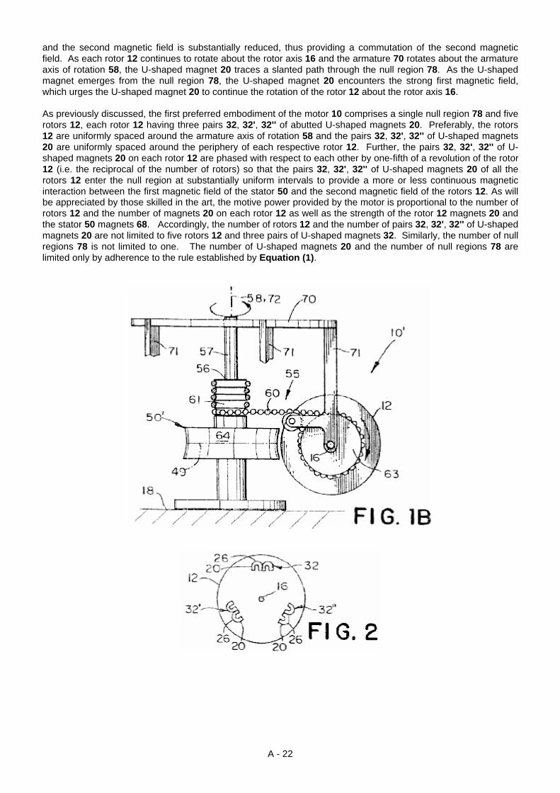
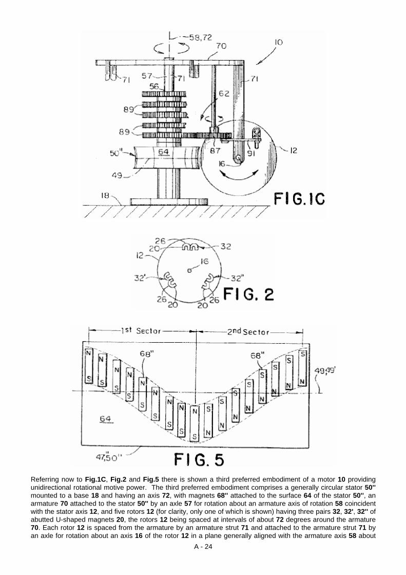
Referring now to Fig.1C, Fig.2 and Fig.5 there is shown a third preferred embodiment of a motor 10 providing unidirectional rotational motive power. The third preferred embodiment comprises a generally circular stator 50'' mounted to a base 18 and having an axis 72, with magnets 68'' attached to the surface 64 of the stator 50'', an armature 70 attached to the stator 50'' by an axle 57 for rotation about an armature axis of rotation 58 coincident with the stator axis 12, and five rotors 12 (for clarity, only one of which is shown) having three pairs 32, 32', 32'' of abutted U-shaped magnets 20, the rotors 12 being spaced at intervals of about 72 degrees around the armature 70. Each rotor 12 is spaced from the armature by an armature strut 71 and attached to the armature strut 71 by an axle for rotation about an axis 16 of the rotor 12 in a plane generally aligned with the armature axis 58 about
A - 25
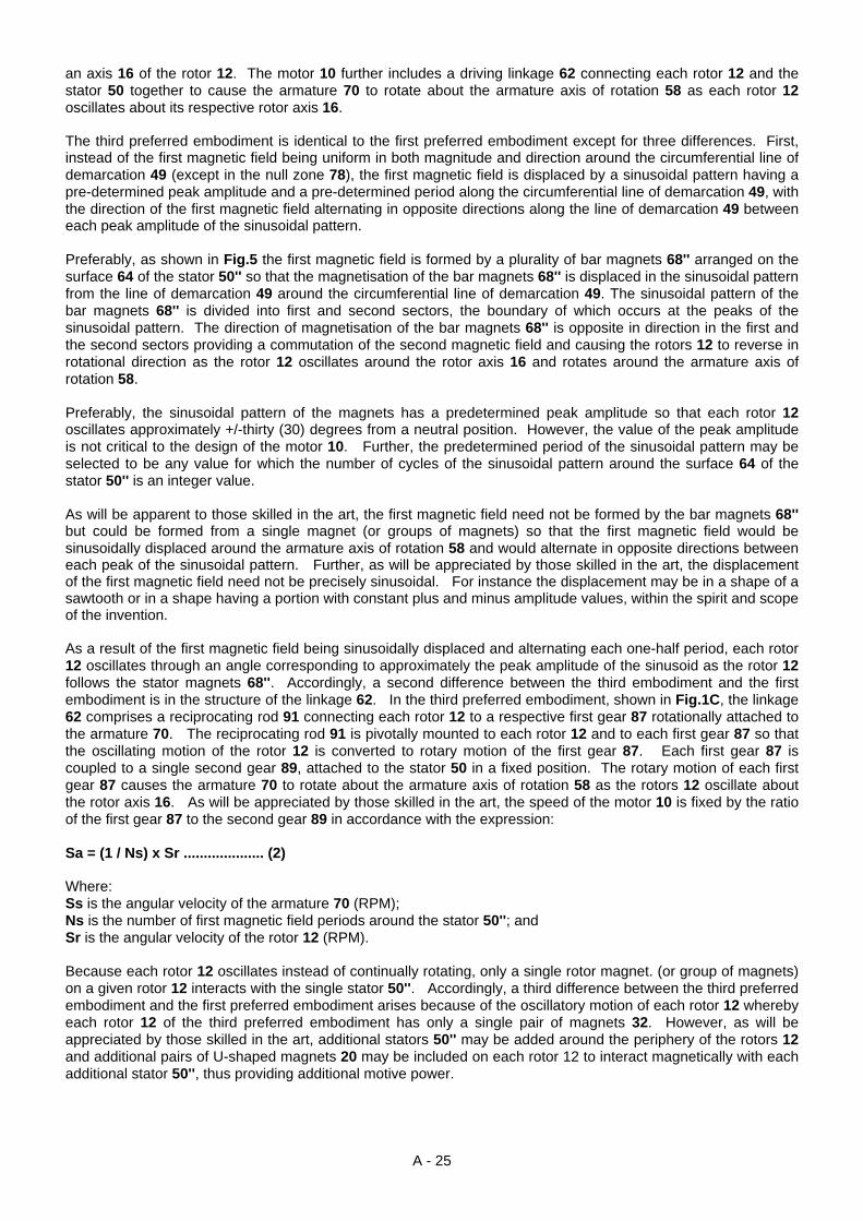
an axis 16 of the rotor 12. The motor 10 further includes a driving linkage 62 connecting each rotor 12 and the stator 50 together to cause the armature 70 to rotate about the armature axis of rotation 58 as each rotor 12 oscillates about its respective rotor axis 16. The third preferred embodiment is identical to the first preferred embodiment except for three differences. First, instead of the first magnetic field being uniform in both magnitude and direction around the circumferential line of demarcation 49 (except in the null zone 78), the first magnetic field is displaced by a sinusoidal pattern having a pre-determined peak amplitude and a pre-determined period along the circumferential line of demarcation 49, with the direction of the first magnetic field alternating in opposite directions along the line of demarcation 49 between each peak amplitude of the sinusoidal pattern. Preferably, as shown in Fig.5 the first magnetic field is formed by a plurality of bar magnets 68'' arranged on the surface 64 of the stator 50'' so that the magnetisation of the bar magnets 68'' is displaced in the sinusoidal pattern from the line of demarcation 49 around the circumferential line of demarcation 49. The sinusoidal pattern of the bar magnets 68'' is divided into first and second sectors, the boundary of which occurs at the peaks of the sinusoidal pattern. The direction of magnetisation of the bar magnets 68'' is opposite in direction in the first and the second sectors providing a commutation of the second magnetic field and causing the rotors 12 to reverse in rotational direction as the rotor 12 oscillates around the rotor axis 16 and rotates around the armature axis of rotation 58. Preferably, the sinusoidal pattern of the magnets has a predetermined peak amplitude so that each rotor 12 oscillates approximately +/-thirty (30) degrees from a neutral position. However, the value of the peak amplitude is not critical to the design of the motor 10. Further, the predetermined period of the sinusoidal pattern may be selected to be any value for which the number of cycles of the sinusoidal pattern around the surface 64 of the stator 50'' is an integer value. As will be apparent to those skilled in the art, the first magnetic field need not be formed by the bar magnets 68'' but could be formed from a single magnet (or groups of magnets) so that the first magnetic field would be sinusoidally displaced around the armature axis of rotation 58 and would alternate in opposite directions between each peak of the sinusoidal pattern. Further, as will be appreciated by those skilled in the art, the displacement of the first magnetic field need not be precisely sinusoidal. For instance the displacement may be in a shape of a sawtooth or in a shape having a portion with constant plus and minus amplitude values, within the spirit and scope of the invention. As a result of the first magnetic field being sinusoidally displaced and alternating each one-half period, each rotor 12 oscillates through an angle corresponding to approximately the peak amplitude of the sinusoid as the rotor 12 follows the stator magnets 68''. Accordingly, a second difference between the third embodiment and the first embodiment is in the structure of the linkage 62. In the third preferred embodiment, shown in Fig.1C, the linkage 62 comprises a reciprocating rod 91 connecting each rotor 12 to a respective first gear 87 rotationally attached to the armature 70. The reciprocating rod 91 is pivotally mounted to each rotor 12 and to each first gear 87 so that the oscillating motion of the rotor 12 is converted to rotary motion of the first gear 87. Each first gear 87 is coupled to a single second gear 89, attached to the stator 50 in a fixed position. The rotary motion of each first gear 87 causes the armature 70 to rotate about the armature axis of rotation 58 as the rotors 12 oscillate about the rotor axis 16. As will be appreciated by those skilled in the art, the speed of the motor 10 is fixed by the ratio of the first gear 87 to the second gear 89 in accordance with the expression: Sa = (1 / Ns) x Sr .................... (2) Where: Ss is the angular velocity of the armature 70 (RPM); Ns is the number of first magnetic field periods around the stator 50''; and Sr is the angular velocity of the rotor 12 (RPM). Because each rotor 12 oscillates instead of continually rotating, only a single rotor magnet. (or group of magnets) on a given rotor 12 interacts with the single stator 50''. Accordingly, a third difference between the third preferred embodiment and the first preferred embodiment arises because of the oscillatory motion of each rotor 12 whereby each rotor 12 of the third preferred embodiment has only a single pair of magnets 32. However, as will be appreciated by those skilled in the art, additional stators 50'' may be added around the periphery of the rotors 12 and additional pairs of U-shaped magnets 20 may be included on each rotor 12 to interact magnetically with each additional stator 50'', thus providing additional motive power.
A - 26
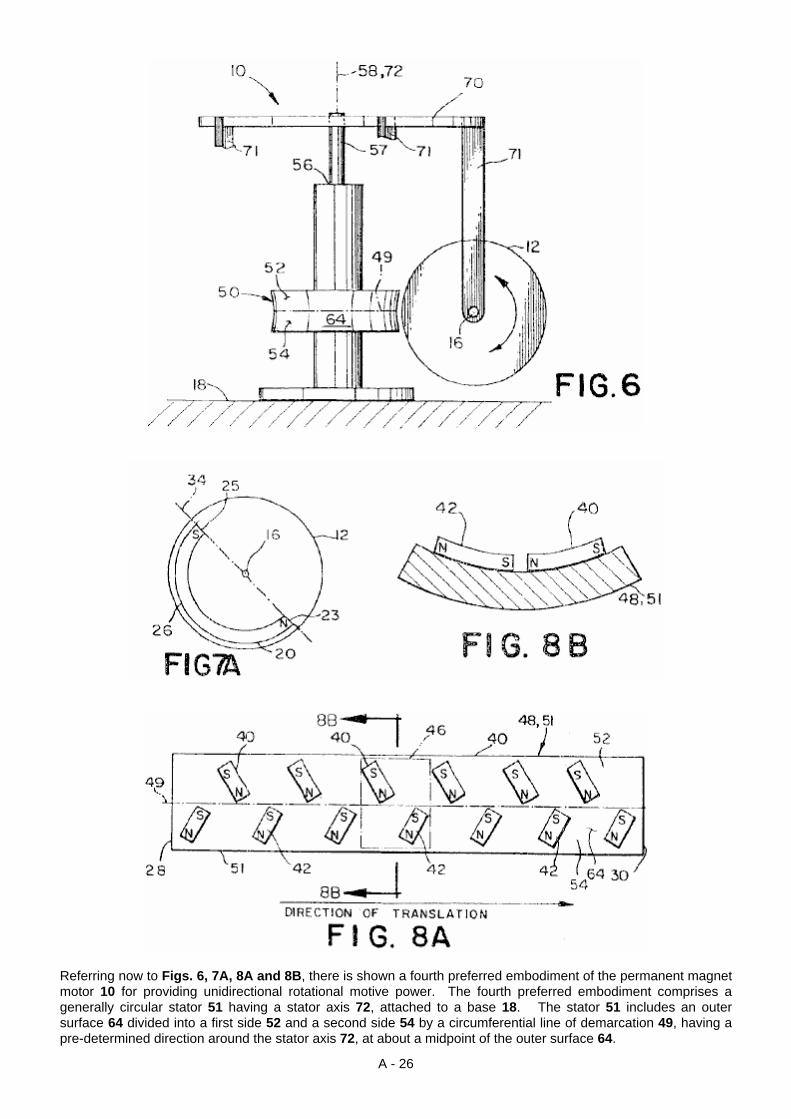
Referring now to Figs. 6, 7A, 8A and 8B, there is shown a fourth preferred embodiment of the permanent magnet motor 10 for providing unidirectional rotational motive power. The fourth preferred embodiment comprises a generally circular stator 51 having a stator axis 72, attached to a base 18. The stator 51 includes an outer surface 64 divided into a first side 52 and a second side 54 by a circumferential line of demarcation 49, having a pre-determined direction around the stator axis 72, at about a midpoint of the outer surface 64.
A - 27
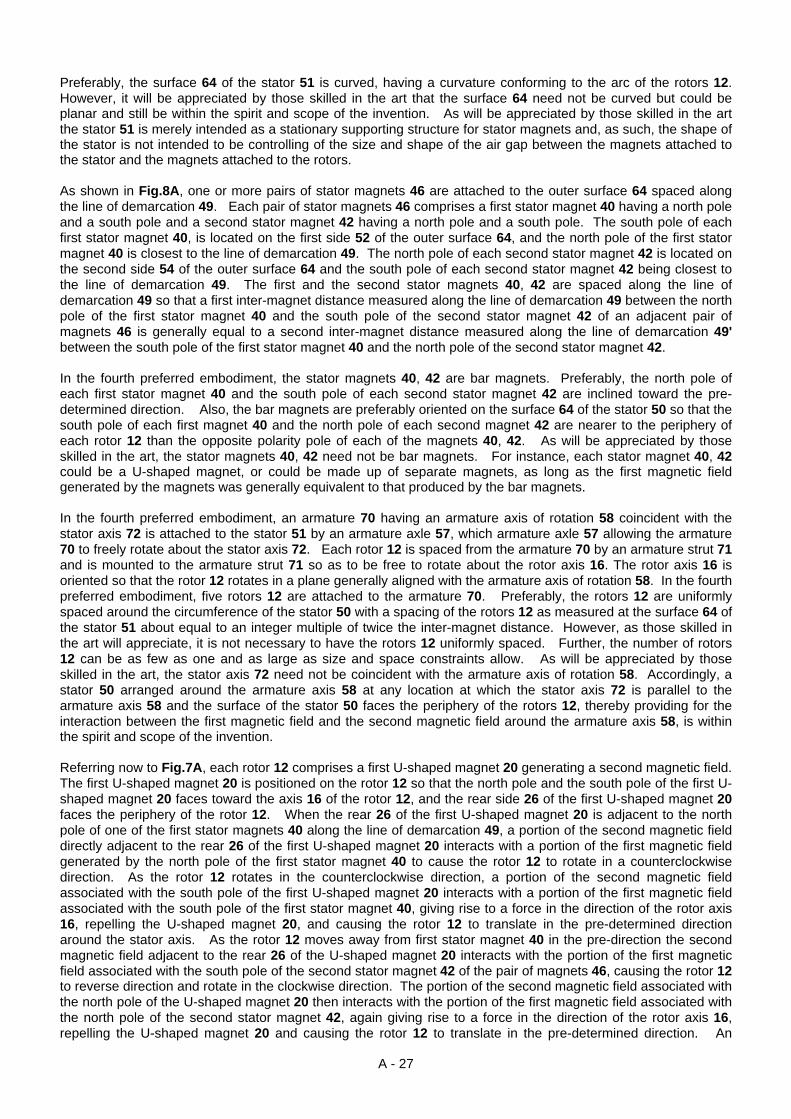
Preferably, the surface 64 of the stator 51 is curved, having a curvature conforming to the arc of the rotors 12. However, it will be appreciated by those skilled in the art that the surface 64 need not be curved but could be planar and still be within the spirit and scope of the invention. As will be appreciated by those skilled in the art the stator 51 is merely intended as a stationary supporting structure for stator magnets and, as such, the shape of the stator is not intended to be controlling of the size and shape of the air gap between the magnets attached to the stator and the magnets attached to the rotors. As shown in Fig.8A, one or more pairs of stator magnets 46 are attached to the outer surface 64 spaced along the line of demarcation 49. Each pair of stator magnets 46 comprises a first stator magnet 40 having a north pole and a south pole and a second stator magnet 42 having a north pole and a south pole. The south pole of each first stator magnet 40, is located on the first side 52 of the outer surface 64, and the north pole of the first stator magnet 40 is closest to the line of demarcation 49. The north pole of each second stator magnet 42 is located on the second side 54 of the outer surface 64 and the south pole of each second stator magnet 42 being closest to the line of demarcation 49. The first and the second stator magnets 40, 42 are spaced along the line of demarcation 49 so that a first inter-magnet distance measured along the line of demarcation 49 between the north pole of the first stator magnet 40 and the south pole of the second stator magnet 42 of an adjacent pair of magnets 46 is generally equal to a second inter-magnet distance measured along the line of demarcation 49' between the south pole of the first stator magnet 40 and the north pole of the second stator magnet 42. In the fourth preferred embodiment, the stator magnets 40, 42 are bar magnets. Preferably, the north pole of each first stator magnet 40 and the south pole of each second stator magnet 42 are inclined toward the pre-determined direction. Also, the bar magnets are preferably oriented on the surface 64 of the stator 50 so that the south pole of each first magnet 40 and the north pole of each second magnet 42 are nearer to the periphery of each rotor 12 than the opposite polarity pole of each of the magnets 40, 42. As will be appreciated by those skilled in the art, the stator magnets 40, 42 need not be bar magnets. For instance, each stator magnet 40, 42 could be a U-shaped magnet, or could be made up of separate magnets, as long as the first magnetic field generated by the magnets was generally equivalent to that produced by the bar magnets. In the fourth preferred embodiment, an armature 70 having an armature axis of rotation 58 coincident with the stator axis 72 is attached to the stator 51 by an armature axle 57, which armature axle 57 allowing the armature 70 to freely rotate about the stator axis 72. Each rotor 12 is spaced from the armature 70 by an armature strut 71 and is mounted to the armature strut 71 so as to be free to rotate about the rotor axis 16. The rotor axis 16 is oriented so that the rotor 12 rotates in a plane generally aligned with the armature axis of rotation 58. In the fourth preferred embodiment, five rotors 12 are attached to the armature 70. Preferably, the rotors 12 are uniformly spaced around the circumference of the stator 50 with a spacing of the rotors 12 as measured at the surface 64 of the stator 51 about equal to an integer multiple of twice the inter-magnet distance. However, as those skilled in the art will appreciate, it is not necessary to have the rotors 12 uniformly spaced. Further, the number of rotors 12 can be as few as one and as large as size and space constraints allow. As will be appreciated by those skilled in the art, the stator axis 72 need not be coincident with the armature axis of rotation 58. Accordingly, a stator 50 arranged around the armature axis 58 at any location at which the stator axis 72 is parallel to the armature axis 58 and the surface of the stator 50 faces the periphery of the rotors 12, thereby providing for the interaction between the first magnetic field and the second magnetic field around the armature axis 58, is within the spirit and scope of the invention. Referring now to Fig.7A, each rotor 12 comprises a first U-shaped magnet 20 generating a second magnetic field. The first U-shaped magnet 20 is positioned on the rotor 12 so that the north pole and the south pole of the first U-shaped magnet 20 faces toward the axis 16 of the rotor 12, and the rear side 26 of the first U-shaped magnet 20 faces the periphery of the rotor 12. When the rear 26 of the first U-shaped magnet 20 is adjacent to the north pole of one of the first stator magnets 40 along the line of demarcation 49, a portion of the second magnetic field directly adjacent to the rear 26 of the first U-shaped magnet 20 interacts with a portion of the first magnetic field generated by the north pole of the first stator magnet 40 to cause the rotor 12 to rotate in a counterclockwise direction. As the rotor 12 rotates in the counterclockwise direction, a portion of the second magnetic field associated with the south pole of the first U-shaped magnet 20 interacts with a portion of the first magnetic field associated with the south pole of the first stator magnet 40, giving rise to a force in the direction of the rotor axis 16, repelling the U-shaped magnet 20, and causing the rotor 12 to translate in the pre-determined direction around the stator axis. As the rotor 12 moves away from first stator magnet 40 in the pre-direction the second magnetic field adjacent to the rear 26 of the U-shaped magnet 20 interacts with the portion of the first magnetic field associated with the south pole of the second stator magnet 42 of the pair of magnets 46, causing the rotor 12 to reverse direction and rotate in the clockwise direction. The portion of the second magnetic field associated with the north pole of the U-shaped magnet 20 then interacts with the portion of the first magnetic field associated with the north pole of the second stator magnet 42, again giving rise to a force in the direction of the rotor axis 16, repelling the U-shaped magnet 20 and causing the rotor 12 to translate in the pre-determined direction. An
A - 28
oscillation cycle is then repeated with the second magnetic field of the rotor 12 interacting with the first magnetic field of the adjacent pair of magnets 46. Accordingly, the rotor 12 rotationally oscillates about the respective rotor axis 16 and generates a force in the direction of the rotor axis 16, causing the armature 70 to rotate in the pre-determined direction around the armature axis of rotation 58 to provide the unidirectional rotational motive power of the motor. As would be appreciated by those skilled in the art, the fourth embodiment is not limited to a single stator 51 and a single U-shaped magnet 20. Additional stators having first and second stator magnets 40, 42 arranged identically to the stator 51 to interact with corresponding U-shaped magnets spaced around the periphery of each rotor are with in the spirit and scope of the invention.
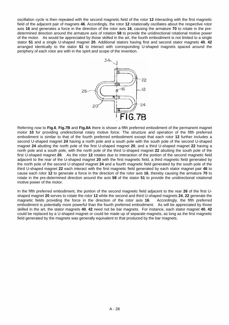
Referring now to Fig.6, Fig.7B and Fig.8A there is shown a fifth preferred embodiment of the permanent magnet motor 10 for providing unidirectional rotary motive force. The structure and operation of the fifth preferred embodiment is similar to that of the fourth preferred embodiment except that each rotor 12 further includes a second U-shaped magnet 24 having a north pole and a south pole with the south pole of the second U-shaped magnet 24 abutting the north pole of the first U-shaped magnet 20, and a third U-shaped magnet 22 having a north pole and a south pole, with the north pole of the third U-shaped magnet 22 abutting the south pole of the first U-shaped magnet 20. As the rotor 12 rotates due to interaction of the portion of the second magnetic field adjacent to the rear of the U-shaped magnet 20 with the first magnetic field, a third magnetic field generated by the north pole of the second U-shaped magnet 24 and a fourth magnetic field generated by the south pole of the third U-shaped magnet 22 each interact with the first magnetic field generated by each stator magnet pair 46 to cause each rotor 12 to generate a force in the direction of the rotor axis 16, thereby causing the armature 70 to rotate in the pre-determined direction around the axis 58 of the stator 51 to provide the unidirectional rotational motive power of the motor. In the fifth preferred embodiment, the portion of the second magnetic field adjacent to the rear 26 of the first U-shaped magnet 20 serves to rotate the rotor 12 while the second and third U-shaped magnets 24, 22 generate the magnetic fields providing the force in the direction of the rotor axis 16. Accordingly, the fifth preferred embodiment is potentially more powerful than the fourth preferred embodiment. As will be appreciated by those skilled in the art, the stator magnets 40, 42 need not be bar magnets. For instance, each stator magnet 40, 42 could be replaced by a U-shaped magnet or could be made up of separate magnets, as long as the first magnetic field generated by the magnets was generally equivalent to that produced by the bar magnets.

A - 29
A - 30
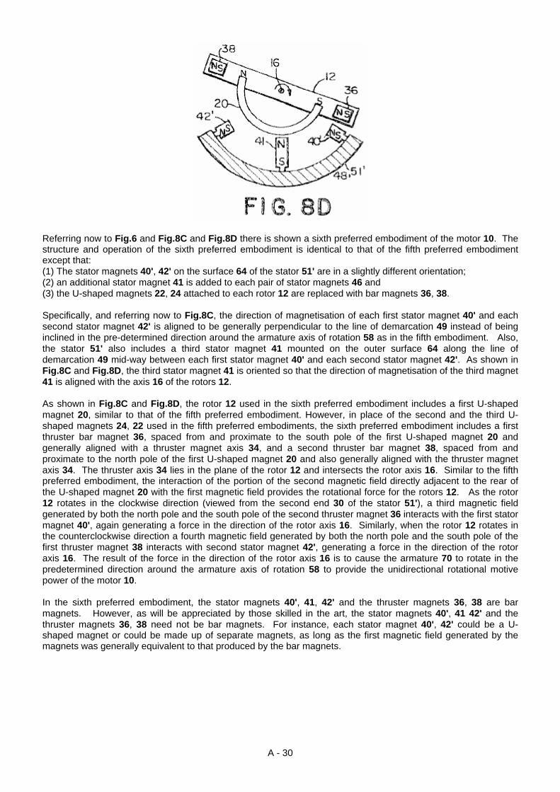
Referring now to Fig.6 and Fig.8C and Fig.8D there is shown a sixth preferred embodiment of the motor 10. The structure and operation of the sixth preferred embodiment is identical to that of the fifth preferred embodiment except that: (1) The stator magnets 40', 42' on the surface 64 of the stator 51' are in a slightly different orientation; (2) an additional stator magnet 41 is added to each pair of stator magnets 46 and (3) the U-shaped magnets 22, 24 attached to each rotor 12 are replaced with bar magnets 36, 38. Specifically, and referring now to Fig.8C, the direction of magnetisation of each first stator magnet 40' and each second stator magnet 42' is aligned to be generally perpendicular to the line of demarcation 49 instead of being inclined in the pre-determined direction around the armature axis of rotation 58 as in the fifth embodiment. Also, the stator 51' also includes a third stator magnet 41 mounted on the outer surface 64 along the line of demarcation 49 mid-way between each first stator magnet 40' and each second stator magnet 42'. As shown in Fig.8C and Fig.8D, the third stator magnet 41 is oriented so that the direction of magnetisation of the third magnet 41 is aligned with the axis 16 of the rotors 12. As shown in Fig.8C and Fig.8D, the rotor 12 used in the sixth preferred embodiment includes a first U-shaped magnet 20, similar to that of the fifth preferred embodiment. However, in place of the second and the third U-shaped magnets 24, 22 used in the fifth preferred embodiments, the sixth preferred embodiment includes a first thruster bar magnet 36, spaced from and proximate to the south pole of the first U-shaped magnet 20 and generally aligned with a thruster magnet axis 34, and a second thruster bar magnet 38, spaced from and proximate to the north pole of the first U-shaped magnet 20 and also generally aligned with the thruster magnet axis 34. The thruster axis 34 lies in the plane of the rotor 12 and intersects the rotor axis 16. Similar to the fifth preferred embodiment, the interaction of the portion of the second magnetic field directly adjacent to the rear of the U-shaped magnet 20 with the first magnetic field provides the rotational force for the rotors 12. As the rotor 12 rotates in the clockwise direction (viewed from the second end 30 of the stator 51'), a third magnetic field generated by both the north pole and the south pole of the second thruster magnet 36 interacts with the first stator magnet 40', again generating a force in the direction of the rotor axis 16. Similarly, when the rotor 12 rotates in the counterclockwise direction a fourth magnetic field generated by both the north pole and the south pole of the first thruster magnet 38 interacts with second stator magnet 42', generating a force in the direction of the rotor axis 16. The result of the force in the direction of the rotor axis 16 is to cause the armature 70 to rotate in the predetermined direction around the armature axis of rotation 58 to provide the unidirectional rotational motive power of the motor 10. In the sixth preferred embodiment, the stator magnets 40', 41, 42' and the thruster magnets 36, 38 are bar magnets. However, as will be appreciated by those skilled in the art, the stator magnets 40', 41 42' and the thruster magnets 36, 38 need not be bar magnets. For instance, each stator magnet 40', 42' could be a U-shaped magnet or could be made up of separate magnets, as long as the first magnetic field generated by the magnets was generally equivalent to that produced by the bar magnets.

A - 31
Referring now to Fig.6, Fig.7D and Fig.8E there is shown a seventh preferred embodiment of the motor 10. The structure and operation of the seventh preferred embodiment is similar to the sixth preferred embodiment except that the third stator magnet 41' located on the surface 64 of the stator 51'' along the line of demarcation 49 is a U-shaped magnet 41' with the rear of the U-shaped magnet 41' facing the rotor 12 and the direction of magnetisation being perpendicular to the line of demarcation 49; and the U-shaped magnet 20 is replaced with a bar magnet 20' oriented to have the direction of magnetisation aligned with a radial line of the rotor 12. As in the sixth preferred embodiment, each stator magnet 40', 42' could be a U-shaped magnet or could be made up of separate magnets, as long as the first magnetic field generated by the stator magnets 40', 42' was generally equivalent to that produced by the bar magnets.
A - 32
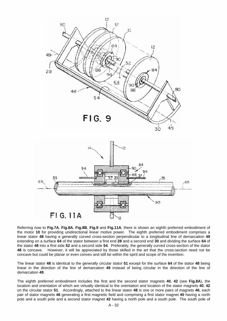
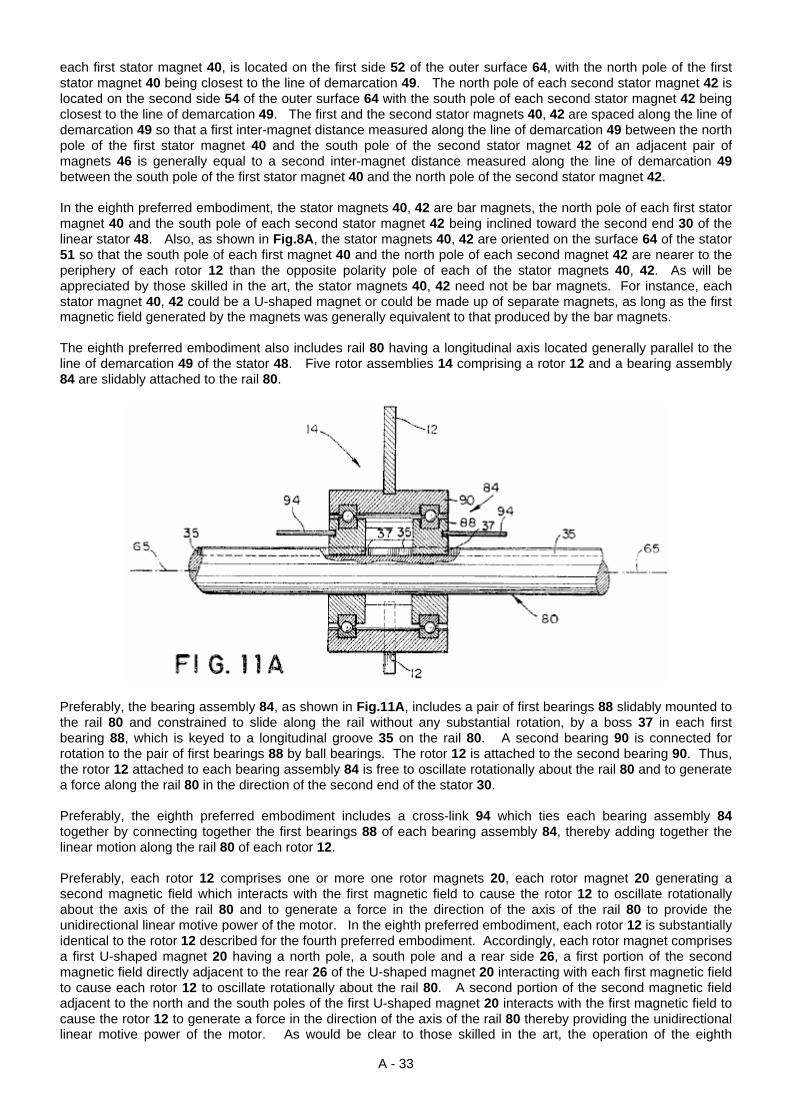
Referring now to Fig.7A, Fig.8A, Fig.8B, Fig.9 and Fig.11A, there is shown an eighth preferred embodiment of the motor 10 for providing unidirectional linear motive power. The eighth preferred embodiment comprises a linear stator 48 having a generally curved cross-section perpendicular to a longitudinal line of demarcation 49 extending on a surface 64 of the stator between a first end 28 and a second end 30 and dividing the surface 64 of the stator 48 into a first side 52 and a second side 54. Preferably, the generally curved cross-section of the stator 48 is concave. However, it will be appreciated by those skilled in the art that the cross-section need not be concave but could be planar or even convex and still be within the spirit and scope of the invention. The linear stator 48 is identical to the generally circular stator 51 except for the surface 64 of the stator 48 being linear in the direction of the line of demarcation 49 instead of being circular in the direction of the line of demarcation 49. The eighth preferred embodiment includes the first and the second stator magnets 40, 42 (see Fig.8A), the location and orientation of which are virtually identical to the orientation and location of the stator magnets 40, 42 on the circular stator 51. Accordingly, attached to the linear stator 48 is one or more pairs of magnets 46, each pair of stator magnets 46 generating a first magnetic field and comprising a first stator magnet 40 having a north pole and a south pole and a second stator magnet 42 having a north pole and a south pole. The south pole of
A - 33
each first stator magnet 40, is located on the first side 52 of the outer surface 64, with the north pole of the first stator magnet 40 being closest to the line of demarcation 49. The north pole of each second stator magnet 42 is located on the second side 54 of the outer surface 64 with the south pole of each second stator magnet 42 being closest to the line of demarcation 49. The first and the second stator magnets 40, 42 are spaced along the line of demarcation 49 so that a first inter-magnet distance measured along the line of demarcation 49 between the north pole of the first stator magnet 40 and the south pole of the second stator magnet 42 of an adjacent pair of magnets 46 is generally equal to a second inter-magnet distance measured along the line of demarcation 49 between the south pole of the first stator magnet 40 and the north pole of the second stator magnet 42. In the eighth preferred embodiment, the stator magnets 40, 42 are bar magnets, the north pole of each first stator magnet 40 and the south pole of each second stator magnet 42 being inclined toward the second end 30 of the linear stator 48. Also, as shown in Fig.8A, the stator magnets 40, 42 are oriented on the surface 64 of the stator 51 so that the south pole of each first magnet 40 and the north pole of each second magnet 42 are nearer to the periphery of each rotor 12 than the opposite polarity pole of each of the stator magnets 40, 42. As will be appreciated by those skilled in the art, the stator magnets 40, 42 need not be bar magnets. For instance, each stator magnet 40, 42 could be a U-shaped magnet or could be made up of separate magnets, as long as the first magnetic field generated by the magnets was generally equivalent to that produced by the bar magnets. The eighth preferred embodiment also includes rail 80 having a longitudinal axis located generally parallel to the line of demarcation 49 of the stator 48. Five rotor assemblies 14 comprising a rotor 12 and a bearing assembly 84 are slidably attached to the rail 80.
Preferably, the bearing assembly 84, as shown in Fig.11A, includes a pair of first bearings 88 slidably mounted to the rail 80 and constrained to slide along the rail without any substantial rotation, by a boss 37 in each first bearing 88, which is keyed to a longitudinal groove 35 on the rail 80. A second bearing 90 is connected for rotation to the pair of first bearings 88 by ball bearings. The rotor 12 is attached to the second bearing 90. Thus, the rotor 12 attached to each bearing assembly 84 is free to oscillate rotationally about the rail 80 and to generate a force along the rail 80 in the direction of the second end of the stator 30. Preferably, the eighth preferred embodiment includes a cross-link 94 which ties each bearing assembly 84 together by connecting together the first bearings 88 of each bearing assembly 84, thereby adding together the linear motion along the rail 80 of each rotor 12. Preferably, each rotor 12 comprises one or more one rotor magnets 20, each rotor magnet 20 generating a second magnetic field which interacts with the first magnetic field to cause the rotor 12 to oscillate rotationally about the axis of the rail 80 and to generate a force in the direction of the axis of the rail 80 to provide the unidirectional linear motive power of the motor. In the eighth preferred embodiment, each rotor 12 is substantially identical to the rotor 12 described for the fourth preferred embodiment. Accordingly, each rotor magnet comprises a first U-shaped magnet 20 having a north pole, a south pole and a rear side 26, a first portion of the second magnetic field directly adjacent to the rear 26 of the U-shaped magnet 20 interacting with each first magnetic field to cause each rotor 12 to oscillate rotationally about the rail 80. A second portion of the second magnetic field adjacent to the north and the south poles of the first U-shaped magnet 20 interacts with the first magnetic field to cause the rotor 12 to generate a force in the direction of the axis of the rail 80 thereby providing the unidirectional linear motive power of the motor. As would be clear to those skilled in the art, the operation of the eighth

A - 34
preferred embodiment is identical to that of the fourth preferred embodiment except that the motion of the cross-linked rotors 12 is linear along the rail 80 instead of being rotational about the armature axis of rotation 58. Accordingly, for the sake of brevity, a description of the operation of the eighth preferred embodiment is not repeated. Referring now to Fig.7B, Fig.8A, Fig.8B, Fig.9 and Fig.11A there is shown a ninth preferred embodiment of the motor 10 for providing unidirectional linear motive power. As would be apparent to those skilled in the art, the structure and the operation of the ninth preferred embodiment is virtually identical to that of the fifth preferred embodiment except that the motion of the cross-linked rotors 12 is linear instead of rotational about the armature axis of rotation 58. Accordingly, for the sake of brevity, a description of the structure and the operation of the ninth preferred embodiment is not repeated. Referring now to Figs. 7C, 8C, 8D, 9 and 11A there is shown a tenth preferred embodiment of the motor 10 for providing unidirectional linear motive power. As would be apparent to those skilled in the art, the structure and the operation of the tenth preferred embodiment is virtually identical to that of the sixth preferred embodiment except that the motion of the cross-linked rotors 12 is linear instead of rotational about the armature axis of rotation 58. Accordingly, for the sake of brevity, the operation of the tenth preferred embodiment is not repeated. Referring now to Figs. 7D, 8C, 8E, 9 and 11A there is shown an eleventh preferred embodiment of the motor 10 for providing unidirectional linear motive power. The structure and operation of the eleventh preferred embodiment is virtually identical to the seventh preferred embodiment except that the motion of the cross-lined rotors 12 is linear instead of rotational about the armature axis of rotation 58. Accordingly, for the sake of brevity, the operation of the tenth preferred embodiment is not repeated.
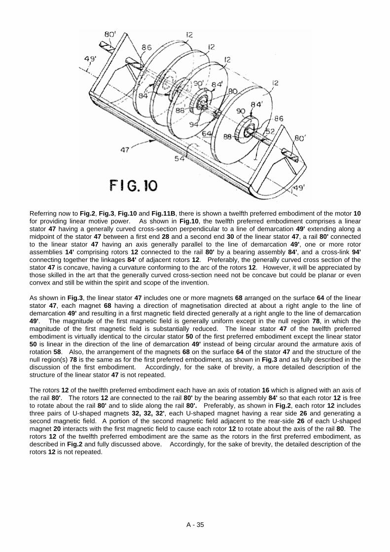
A - 35
Referring now to Fig.2, Fig.3, Fig.10 and Fig.11B, there is shown a twelfth preferred embodiment of the motor 10 for providing linear motive power. As shown in Fig.10, the twelfth preferred embodiment comprises a linear stator 47 having a generally curved cross-section perpendicular to a line of demarcation 49' extending along a midpoint of the stator 47 between a first end 28 and a second end 30 of the linear stator 47, a rail 80' connected to the linear stator 47 having an axis generally parallel to the line of demarcation 49', one or more rotor assemblies 14' comprising rotors 12 connected to the rail 80' by a bearing assembly 84', and a cross-link 94' connecting together the linkages 84' of adjacent rotors 12. Preferably, the generally curved cross section of the stator 47 is concave, having a curvature conforming to the arc of the rotors 12. However, it will be appreciated by those skilled in the art that the generally curved cross-section need not be concave but could be planar or even convex and still be within the spirit and scope of the invention. As shown in Fig.3, the linear stator 47 includes one or more magnets 68 arranged on the surface 64 of the linear stator 47, each magnet 68 having a direction of magnetisation directed at about a right angle to the line of demarcation 49' and resulting in a first magnetic field directed generally at a right angle to the line of demarcation 49'. The magnitude of the first magnetic field is generally uniform except in the null region 78, in which the magnitude of the first magnetic field is substantially reduced. The linear stator 47 of the twelfth preferred embodiment is virtually identical to the circular stator 50 of the first preferred embodiment except the linear stator 50 is linear in the direction of the line of demarcation 49' instead of being circular around the armature axis of rotation 58. Also, the arrangement of the magnets 68 on the surface 64 of the stator 47 and the structure of the null region(s) 78 is the same as for the first preferred embodiment, as shown in Fig.3 and as fully described in the discussion of the first embodiment. Accordingly, for the sake of brevity, a more detailed description of the structure of the linear stator 47 is not repeated. The rotors 12 of the twelfth preferred embodiment each have an axis of rotation 16 which is aligned with an axis of the rail 80'. The rotors 12 are connected to the rail 80' by the bearing assembly 84' so that each rotor 12 is free to rotate about the rail 80' and to slide along the rail 80'. Preferably, as shown in Fig.2, each rotor 12 includes three pairs of U-shaped magnets 32, 32, 32', each U-shaped magnet having a rear side 26 and generating a second magnetic field. A portion of the second magnetic field adjacent to the rear-side 26 of each U-shaped magnet 20 interacts with the first magnetic field to cause each rotor 12 to rotate about the axis of the rail 80. The rotors 12 of the twelfth preferred embodiment are the same as the rotors in the first preferred embodiment, as described in Fig.2 and fully discussed above. Accordingly, for the sake of brevity, the detailed description of the rotors 12 is not repeated.
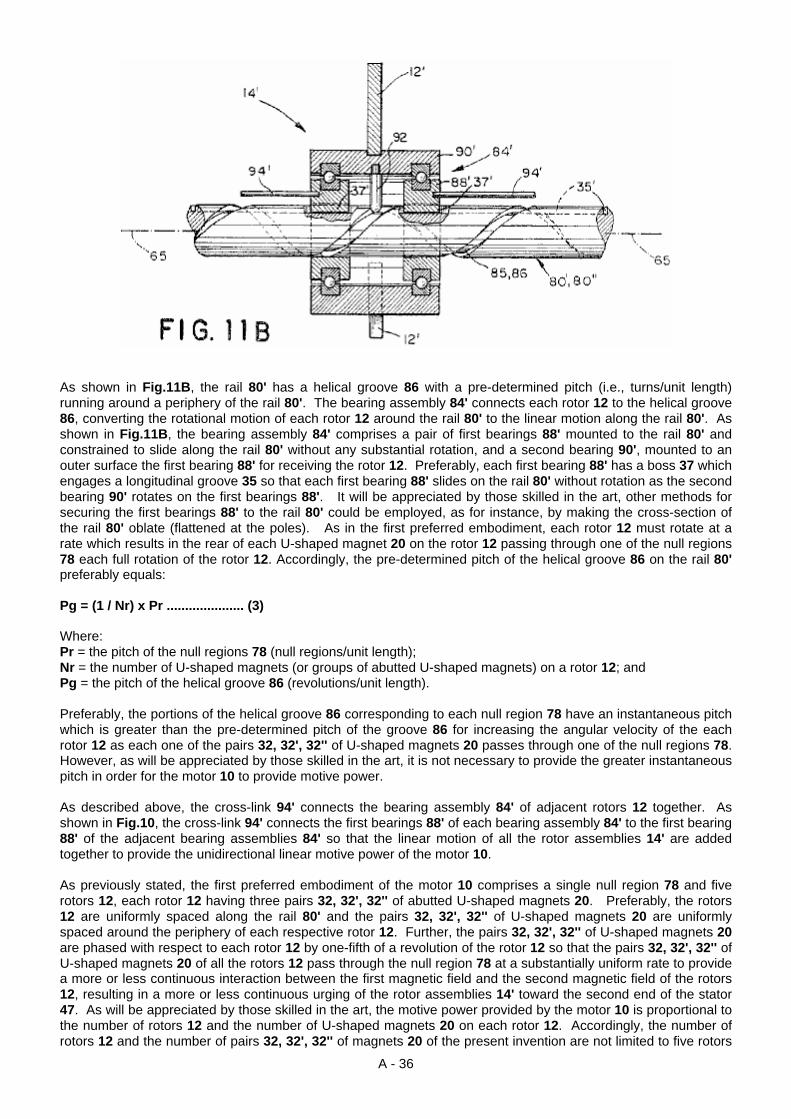
A - 36
As shown in Fig.11B, the rail 80' has a helical groove 86 with a pre-determined pitch (i.e., turns/unit length) running around a periphery of the rail 80'. The bearing assembly 84' connects each rotor 12 to the helical groove 86, converting the rotational motion of each rotor 12 around the rail 80' to the linear motion along the rail 80'. As shown in Fig.11B, the bearing assembly 84' comprises a pair of first bearings 88' mounted to the rail 80' and constrained to slide along the rail 80' without any substantial rotation, and a second bearing 90', mounted to an outer surface the first bearing 88' for receiving the rotor 12. Preferably, each first bearing 88' has a boss 37 which engages a longitudinal groove 35 so that each first bearing 88' slides on the rail 80' without rotation as the second bearing 90' rotates on the first bearings 88'. It will be appreciated by those skilled in the art, other methods for securing the first bearings 88' to the rail 80' could be employed, as for instance, by making the cross-section of the rail 80' oblate (flattened at the poles). As in the first preferred embodiment, each rotor 12 must rotate at a rate which results in the rear of each U-shaped magnet 20 on the rotor 12 passing through one of the null regions 78 each full rotation of the rotor 12. Accordingly, the pre-determined pitch of the helical groove 86 on the rail 80' preferably equals: Pg = (1 / Nr) x Pr ..................... (3) Where: Pr = the pitch of the null regions 78 (null regions/unit length); Nr = the number of U-shaped magnets (or groups of abutted U-shaped magnets) on a rotor 12; and Pg = the pitch of the helical groove 86 (revolutions/unit length). Preferably, the portions of the helical groove 86 corresponding to each null region 78 have an instantaneous pitch which is greater than the pre-determined pitch of the groove 86 for increasing the angular velocity of the each rotor 12 as each one of the pairs 32, 32', 32'' of U-shaped magnets 20 passes through one of the null regions 78. However, as will be appreciated by those skilled in the art, it is not necessary to provide the greater instantaneous pitch in order for the motor 10 to provide motive power. As described above, the cross-link 94' connects the bearing assembly 84' of adjacent rotors 12 together. As shown in Fig.10, the cross-link 94' connects the first bearings 88' of each bearing assembly 84' to the first bearing 88' of the adjacent bearing assemblies 84' so that the linear motion of all the rotor assemblies 14' are added together to provide the unidirectional linear motive power of the motor 10. As previously stated, the first preferred embodiment of the motor 10 comprises a single null region 78 and five rotors 12, each rotor 12 having three pairs 32, 32', 32'' of abutted U-shaped magnets 20. Preferably, the rotors 12 are uniformly spaced along the rail 80' and the pairs 32, 32', 32'' of U-shaped magnets 20 are uniformly spaced around the periphery of each respective rotor 12. Further, the pairs 32, 32', 32'' of U-shaped magnets 20 are phased with respect to each rotor 12 by one-fifth of a revolution of the rotor 12 so that the pairs 32, 32', 32'' of U-shaped magnets 20 of all the rotors 12 pass through the null region 78 at a substantially uniform rate to provide a more or less continuous interaction between the first magnetic field and the second magnetic field of the rotors 12, resulting in a more or less continuous urging of the rotor assemblies 14' toward the second end of the stator 47. As will be appreciated by those skilled in the art, the motive power provided by the motor 10 is proportional to the number of rotors 12 and the number of U-shaped magnets 20 on each rotor 12. Accordingly, the number of rotors 12 and the number of pairs 32, 32', 32'' of magnets 20 of the present invention are not limited to five rotors
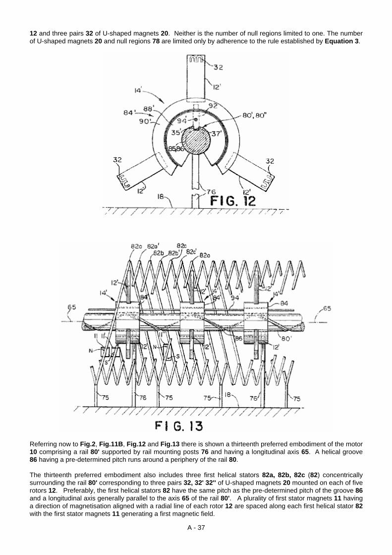
A - 37
12 and three pairs 32 of U-shaped magnets 20. Neither is the number of null regions limited to one. The number of U-shaped magnets 20 and null regions 78 are limited only by adherence to the rule established by Equation 3.
Referring now to Fig.2, Fig.11B, Fig.12 and Fig.13 there is shown a thirteenth preferred embodiment of the motor 10 comprising a rail 80' supported by rail mounting posts 76 and having a longitudinal axis 65. A helical groove 86 having a pre-determined pitch runs around a periphery of the rail 80. The thirteenth preferred embodiment also includes three first helical stators 82a, 82b, 82c (82) concentrically surrounding the rail 80' corresponding to three pairs 32, 32' 32'' of U-shaped magnets 20 mounted on each of five rotors 12. Preferably, the first helical stators 82 have the same pitch as the pre-determined pitch of the groove 86 and a longitudinal axis generally parallel to the axis 65 of the rail 80'. A plurality of first stator magnets 11 having a direction of magnetisation aligned with a radial line of each rotor 12 are spaced along each first helical stator 82 with the first stator magnets 11 generating a first magnetic field.

A - 38
The thirteenth preferred embodiment further includes plurality of second helical stators 82a', 82b', 82c' (82') alternating with the first helical stators 82' along the axis 65 of the rail 80', and having the pre-determined pitch of the groove 86. Each second helical stator 82' has mounted upon it a plurality of second stator magnets 11' having a direction of magnetisation aligned with a radial line of the rotor 12 and having a direction of magnetisation opposite in direction to the first stator magnets 11 mounted on each of the first helical stators 82. As a consequence of the second helical stators 82' being located midway between the first helical stators 82, a point at about a midpoint between each rotor magnet pair 32, 32', 32'' is apposite to one of the second helical stators 82' as each rotor 12 rotates about the axis 65 of the rail 80' and slides along the rail 80'. The thirteenth preferred embodiment also includes five rotors 12, (for clarity, only three are shown), having an axis of rotation 16 generally aligned with the longitudinal axis 65 of the rail 80'. Each rotor 12 is connected to the rail 80' by a bearing assembly 84' so that the rotor 12 is free to rotate about the axis 65 of the rail 80' and slide along the rail 80'. Preferably, each rotor 12 includes three pairs 32, 32', 32'' of U-shaped magnets 20 wherein each U-shaped magnet 20 generates a second magnetic field, a portion of which adjacent to a rear 26 of the pair of U-shaped magnets 20 interacts with the first magnetic field of each first stator magnet to cause each rotor 12 to rotate about the axis 65 of the rail 80'. The bearing assembly 84' (shown in detail in Fig.11B and Fig.12) connects each rotor 12 to the helical groove 86 around the periphery of the rail 80. The bearing assembly 84' is similar to the bearing assembly 84' described in the twelfth preferred embodiment except for the openings in the first bearings 88' and in the second bearing 90' which allow the bearing assembly 84' past the rail mounting posts 76 as the bearing assembly 84' moves along the rail 80'. The thirteenth preferred embodiment may be constructed as either a linear motor or a rotary motor. In the case of the linear motor, the axes of the rail 80' and of each helical stator 82 are substantially straight. The rail 80' is supported on the base 18 by rail mounting posts 76 placed at intervals along the rail 80'. The posts 76 are situated at locations along the rail 80' at which the rotation of the rotor 12 orients the openings in the first and second bearings 88', 90' to correspond to the mounting posts 76. Each helical stator 82a, 82b, 82c is supported on the base by stator mounting posts 75. The rotors 12 are connected together by a cross-link 94' which connects the first bearings 88' of each bearing assembly 84' to the first bearing 88' of the bearing assembly 84' of an adjacent rotor 12. In this manner, the rotational motion of each rotor assembly 14' is added together to provide the linear motive power of the linear motor.
The thirteenth preferred embodiment may also be constructed as a rotary motor 10 as shown in Fig.14. In this case, the axes of the rail 80' and the helical stators 82 are configured to be circular. The circularly configured motor 10 includes an armature 70 centrally located within the perimeter of the rail 80'. The armature 70 rotates

A - 39
about an armature axis of rotation 58 connected for rotation within a motor base 18 to which the rail 80' is also attached by mounting posts 76 (not shown). The pitch of the first and the second helical stators 82, 82', measured at a radius of the rail 80, preferably equals the predetermined pitch of the helical groove 86. The armature 70 is fixedly attached to the first bearing 88 (see Fig.11B) of each bearing assembly 84' by an armature strut 71 thereby adding together the rotational motive power of each rotor assembly 14. In order that the armature strut 71 does not interfere with the first and second helical stators 82, 82', the first and second helical stators 82, 82' are made to have an opening toward the armature axis of rotation 58. Preferably, each first helical stator 82a, 82b, 82c has mounted upon it a plurality of first stator magnets 11 with each stator magnet 11 having a direction of magnetisation aligned with a radial line of the rotor 12. Preferably, the first helical stators 82 are uniformly spaced along the longitudinal axis 65 of the rail 80' with each first helical stator 82 corresponding to one of the plurality of magnet pairs 32, 32', 32''. Preferably, each rotor 12 is positioned on the rail 80' so that one of the rotor magnet pairs 32, 32', 32'' is apposite to one of the corresponding first helical stators 82 as the rotor 12 rotates about the axis 65 of the rail 80 and slides along the rail 80'. However, as those skilled in the art will appreciate, the rotor magnet pairs 32, 32', 32'' need not be directly apposite to each helical stator 82 as the rotors 12 rotate in order to generate a rotational force. Alternatively, as will be appreciated by those skilled in the art, the motor 10 can be constructed without the second helical stator 82'. In the simplest case the motor 10 could comprise only a single first helical stator 82 and a single rotor 12 comprising a single U-shaped magnet 20 generating the second magnetic field. The single rotor 12 is preferably positioned in the groove 86 on the rail 80' so that the U-shaped rotor magnet 20 is continually apposite to the single first helical stator 82. Consequently, a portion of the second magnetic field directly adjacent to a rear 26 of the U-shaped magnet 20 interacts with the first magnetic field generated by each first stator magnet 11'' mounted on the helical stator 82 to cause the rotor 12 to rotate about the axis 65 of the rail 80 and to slide along the rail 80'. Preferably, when only a single first stator 82 set of first stators 82 is used, each first stator magnet 11'' has a direction of magnetisation oriented to be in the plane of the rotor 12 and generally perpendicular to a radial line of the rotor 12. The north pole and the south pole of the first stator magnet 11'' are preferably spaced apart so that when one pole of the first stator magnet 11 is directly apposite to the rotor magnet 20, the pole of opposite polarity is equally spaced from the U-shaped magnet 20 of the rotor 12. As one skilled in the art would appreciate, a plurality of U-shaped rotor magnets 20 and corresponding first helical stators could be used. Further, as those skilled in the art will appreciate, other configurations of the rotor magnet 20 and the stator magnet 11 are possible, all of which rely on the novel attributes of the magnetic field adjacent to the rear 26 of a U-shaped rotor magnet 20. For example, the previously described stator magnet 11'' perpendicular to the radial line of the rotor 12 could be two separate bar magnets, spaced apart, with the magnetisation of each of the two magnets aligned with a radial line of the rotor and having opposite directions of magnetisation.
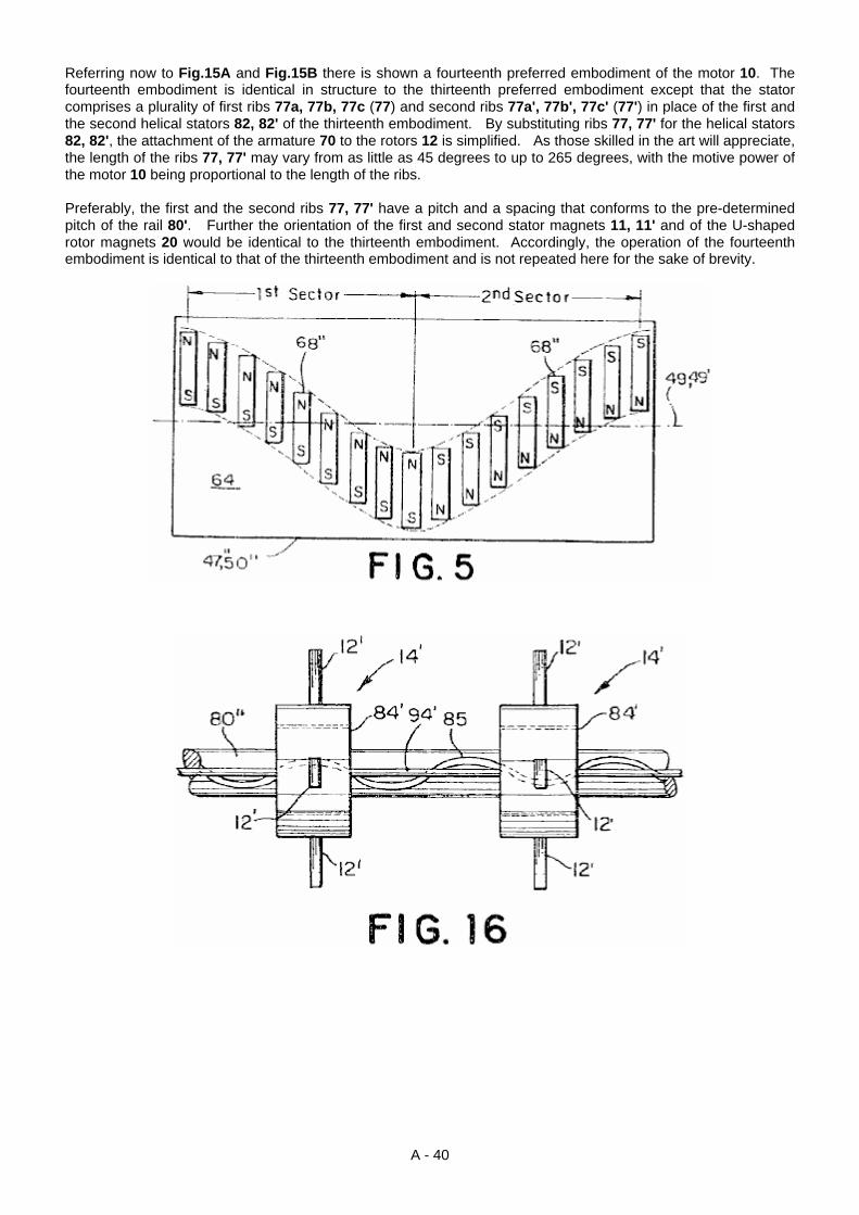
A - 40
Referring now to Fig.15A and Fig.15B there is shown a fourteenth preferred embodiment of the motor 10. The fourteenth embodiment is identical in structure to the thirteenth preferred embodiment except that the stator comprises a plurality of first ribs 77a, 77b, 77c (77) and second ribs 77a', 77b', 77c' (77') in place of the first and the second helical stators 82, 82' of the thirteenth embodiment. By substituting ribs 77, 77' for the helical stators 82, 82', the attachment of the armature 70 to the rotors 12 is simplified. As those skilled in the art will appreciate, the length of the ribs 77, 77' may vary from as little as 45 degrees to up to 265 degrees, with the motive power of the motor 10 being proportional to the length of the ribs. Preferably, the first and the second ribs 77, 77' have a pitch and a spacing that conforms to the pre-determined pitch of the rail 80'. Further the orientation of the first and second stator magnets 11, 11' and of the U-shaped rotor magnets 20 would be identical to the thirteenth embodiment. Accordingly, the operation of the fourteenth embodiment is identical to that of the thirteenth embodiment and is not repeated here for the sake of brevity.

A - 41
Referring now to Fig.5, Fig.16 and Fig.17 there is shown a fifteenth preferred embodiment of the motor 10 comprising a rail 80'' having a longitudinal axis 65 and a generally sinusoidal groove 85 having a pre-determined period running around a periphery of the rail 80''. Preferably, the fifteenth preferred embodiment includes three generally identical stators 50'' arrayed in a circular fashion around the rail 80''. Each stator 50'' has a surface 64 facing the rail 80'' and disposed generally equidistant from and parallel to the axis 65 of the rail 80''. As shown in Fig.5 and Fig.17 each stator 50'' has a generally curved cross-section and a longitudinal line of demarcation 49 perpendicular to the cross-section and located about a midpoint of the surface 64. A plurality of stator magnets 68'' are attached to the surface 64 of the stator 50'' generating a first magnetic field. The stator magnets 68'' are displaced on the surface 64 in a sinusoidal pattern around the line of demarcation 49. The sinusoidal pattern has a pre-determined period and a pre-determined maximum (peak) amplitude along the line of demarcation 49. In the case where the rail 80'' and the longitudinal line of demarcation 49 of the stator 50'' are in a straight line, the period of the sinusoid is preferably equal to the period of the groove 85 on the rail 80. The sinusoidal pattern is also divided into a plurality of first and second alternating sectors with a boundary between the alternating sectors occurring at each maximum (peak) amplitude of the sinusoid. The direction of magnetisation of the stator magnets 68'' is opposite in the first and the second segments so that the direction of the first magnetic field in each first segment is opposite to the direction of the first magnetic field in each second segment. Preferably, the direction of magnetisation of the stator magnets 68'' is generally perpendicular to a radial line of the rotor 12. Alternatively, the direction of magnetisation of the stator magnets 68'' could be generally aligned with a radial line of the rotor 12. Further, as will be apparent to those skilled in the art, the first magnetic field need not be formed by a plurality of bar magnets but could be formed from a single magnet so that the first magnetic field would be sinusoidally displaced from the line of demarcation 49 and would alternate in opposite directions between the peaks of the sinusoid. Further, as will be appreciated by those skilled in the art, the displacement of the first magnetic field need not be precisely sinusoidal. For instance the displacement may be in a shape of a sawtooth or in a shape having a portion with constant plus and minus amplitude values, within the spirit and scope of the invention.

A - 42
Preferably, the fifteenth preferred embodiment includes five rotors 12, each rotor 12 having an axis 16 aligned with the axis of the rail 80''. Each rotor 12 is connected to the rail 80'' by a bearing assembly 84' so that the rotor 12 is free to rotate about the axis of the rail 65 and slide along the rail 80''. Preferably, each rotor 12 includes three U-shaped magnet pairs 32, 32' 32'', each pair comprising two U-shaped magnets 20. Each U-shaped magnet 20 has a rear side and generates a second magnetic field. Each of the U-shaped magnet pairs 32, 32', 32'' is positioned on each rotor 12 so that the rear side 26 of each U-shaped magnet 20 is apposite to the first and the second segments of the sinusoidal pattern as the at least one rotor assembly 14 rotates about the rotor axis 16, wherein an interaction of a portion of the second magnetic field directly adjacent to the rear 26 of each U-shaped magnet 20 with the first magnetic field of a corresponding stator 50'' causes the at least one rotor 12 to oscillate rotationally about the axis 65 of the rail 80''. Those skilled in the art will appreciate that it is not necessary to have three pairs of U-shaped magnets 32, 32', 32''. For instance, the number of U-shaped magnets 20 (or groups of abutted U-shaped magnets) spaced apart around the periphery of the rotor 12 may range from merely a single U-shaped magnet 20, or may range in number up to a number of magnets limited only by the physical space around the periphery of the rotor 12. Further the number of abutted U-shaped magnets 20 in a group of magnets 32 may also range from 1 up to a number of magnets limited only by the physical space around the periphery of the rotor 12. Preferably, the number of stators 50'' equals the number of U-shaped magnet pairs 32, 32', 32''. However, as will be appreciated by those skilled in the art, the number of stators 50'' is not limited to three but could be any number ranging upward from one, where the number of stators 50'' would preferably equal the number of U-shaped magnet pairs 32, 32', 32''. As shown in Fig.16 the bearing assembly 84' converts the oscillatory motion of the at least one rotor 12 about the rail to unidirectional linear motion along the rail 80' by following the sinusoidal groove 85 in the rail 80' with the boss 92 (shown in Fig.11B). A cross-link 94 connects the bearing assembly 84' of adjacent rotors 12 together, thereby adding together the linear motion of each rotor assembly 14' along the rail to provide the unidirectional linear motive power. The structure of the bearing assembly 84' and the cross-link 94 is shown in Fig.11B and Fig.12, and the operation is identical to the linkage 84' and the cross-link 94' described for the twelfth embodiment. Accordingly, a detailed description of the linkage 84' and the cross-link 94 is not repeated, for the sake of brevity. In another aspect, the fifteenth preferred embodiment may also be configured in a circular arrangement similar to that of the fourteenth embodiment. In the fifteenth preferred embodiment, the helical stator 82' shown in Fig.14 is replaced with one or more curved stators 50'' spaced around the rotors 12. In this case, the period of the sinusoidal pattern of the stator magnets is adjusted in accordance with the distance of the surface 64 of the respective stator 50'' from the armature axis of rotation 58 in order that the U-shaped magnets 20 on the rotors 12 remain apposite to the first and the second segments, as the rotors 12 slide along the rail 80''. Accordingly, a description of those elements of circular arrangement of the fifteenth embodiment which are the same as for the linear embodiment are not repeated, for the sake of brevity. Referring now to Fig.4, Fig.18 and Fig.19 there is shown a sixteenth preferred embodiment of the motor 10 for providing unidirectional motive power comprising a rail 80'' having a longitudinal axis 65 and a helical groove 86 having a pre-determined pitch, running around a periphery of the rail 80. Preferably, the sixteenth preferred embodiment further includes three generally identical stators 50', each stator 50' having a surface 64 disposed generally equidistant from and parallel to the axis 65 of the rail 80. Each stator 50' has a longitudinal line of demarcation 49 located about a midpoint of the surface 64. Preferably, a plurality of stator magnets 68' are attached to the surface of the stator 50' generating a first magnetic field. The plurality of stator magnets 68' have a direction of magnetisation which rotates about a magnetic axis parallel to the line of demarcation 49. In the case where the rail 80'' and the longitudinal line of demarcation 49 of the stator 50' are in a straight line, the pitch of the rotation of the stator magnets 68' is preferably equal to the pre-determined pitch of the helical groove 86 on the rail 80. The sixteenth embodiment further includes five rotors 12, each rotor 12 having an axis of rotation 16 aligned with the axis 65 of the rail 80. Each rotor 12 is connected to the rail 80 so that the rotor 12 is free to rotate about the axis 65 of the rail 80 and slide along the rail 80. Each rotor 12 includes three pairs 32, 32', 32'' of U-shaped magnets 20 spaced around the periphery of the rotor 12, each U-shaped magnet 20 generating a second magnetic field. The U-shaped magnets 20 are positioned on each rotor 12 so that a portion of the second magnetic field directly adjacent to the rear side 26 of the U-shaped magnet 20 interacts with the first magnetic field generated by the plurality of stator magnets 68' to cause each rotor 12 to rotate about the rotor axis 16. Those skilled in the art will appreciate that it is not necessary to have exactly three pairs of U-shaped magnets 32, 32', 32''. For instance, the number of U-shaped magnets 20 (or groups of abutted U-shaped magnets) spaced apart around the periphery of the rotor 12 may range from merely a single U-shaped magnet 20, or may range in number up to a number of U shaped magnets 20 limited only by the physical space around the periphery of the

A - 43
rotor 12. Further the number of abutted U-shaped magnets 20 in a group of magnets 32 may also range from 1 up to a number of magnets limited only by the physical space around the periphery of the rotor 12. The sixteenth embodiment also includes a bearing assembly 84' connecting each rotor 12 to the helical groove 86, the bearing assembly 84' converting the rotary motion of each rotor 12 about the rail 80' to unidirectional linear motion along the rail 80'. A cross-link 94 connects the bearing assembly 84' of adjacent rotors 12 together, thereby adding together the linear motion of each rotor assembly 14' along the rail 80' to provide the unidirectional linear motive power. The structure of the bearing assembly 84' and the cross-link 94 is shown in Fig.11B and Fig.12, is identical to the bearing assembly 84' and cross-link 94 described for the twelfth embodiment. Accordingly, a description of the linkage 84 and the cross-link 94 is not repeated, for the sake of brevity. In another aspect of the sixteenth preferred embodiment the motor 10 may be configured in a circular arrangement similar to that of the fourteenth embodiment, as shown in Fig.14, except that the helical stator 82' shown in Fig.14 is replaced with one or more stators 50' spaced around the rotors 12. In this case, the pitch of the rotation of the plurality of stator magnets 68' is adjusted in accordance with the distance of the surface 64 of the respective stator 50' from the armature axis of rotation 58 in order that the U-shaped magnets 20 on the rotors 12 remain aligned with the plurality of stator magnets 68' as the rotors 12 rotate about the axis 65 of the rail 80' and slide along the rail 80'. Accordingly, a description of those elements of the circular arrangement of the sixteenth embodiment which are the same as for the straight line configuration are not repeated, for the sake of brevity. It will be appreciated by those skilled in the art that changes could be made to the embodiments described above without departing from the broad inventive concept thereof. It is understood, therefore, that this invention is not limited to the particular embodiments disclosed, but it is intended to cover modifications within the spirit and scope of the present invention as defined by the appended claims. CLAIMS 1. An apparatus (10, 10') characterised by:
at least one rotor (12) having a periphery and a rotor axis (16), the at least one rotor (12) comprising a first rotor magnet (20) producing a first magnetic field, said first rotor magnet being U-shaped and having a north pole (23), a south pole (25) and a rear side (26), the rear side (26) of the first rotor magnet being adjacent to the periphery; an axle (80) to which the at least one rotor (12) is connected at the rotor axis (16) for rotation of the at least one rotor (12) about the rotor axis (16); and a stationary stator (48, 51) comprising a generally curved cross-section, said stator (51) having a surface (64) opposing the periphery of the at least one rotor (12), and a longitudinal line of demarcation (49) perpendicular to the cross-section at about a midpoint of the surface, the line of demarcation (49) delineating a first side (52) of the surface from a second side (54) of the surface (64), wherein a plurality of pairs of stator magnets (40, 42) producing a second magnetic field are attached to the surface (64), each pair of stator magnets (40, 42) comprising a first stator magnet (40) having a north pole and a south pole and a direction of magnetisation substantially parallel to the surface (64), and a second stator magnet (42) having a north pole and a south pole and a direction of magnetisation substantially parallel to the surface (64), the first stator magnet (40) being on the first side of the surface (64) with the north pole of the first stator magnet being closest to the line of demarcation (49), the second stator magnet (42) being on the second side (52) of the surface with the south pole of the second stator magnet (42) being closest to the line of demarcation (49), wherein the plurality of pairs of stator magnets (40, 42) are spaced along the line of demarcation (49) so that a first inter-magnet distance measured along the line of demarcation (49) between the north pole of the first stator magnet (40) and the south pole of the second stator (42) magnet of an adjacent pair of stator magnets (40, 42) is about equal to a second inter-magnet distance measured along the line of demarcation between the south pole of the first stator magnet (40) and the north pole of the second stator magnet (42), and wherein the interaction of the first and the second magnetic fields cause the at least one rotor (12) to translate in a predetermined direction along the line of demarcation.
2. The apparatus (10, 10') of claim 1, characterised by the north pole of each first stator magnet (40) and the
south pole of each second stator magnet (42) being inclined toward the predetermined direction. 3. The apparatus (10, 10') of claim 1, further characterised by the rotor (12) including a second rotor magnet (22),
said second rotor magnet (24) being U-shaped and having a north pole, a south pole and a rear side, the south pole of the second rotor magnet (22) abutting the north pole of the first rotor magnet (26) and the north pole of the second rotor magnet being adjacent to the periphery, and a third rotor magnet (24), said third rotor
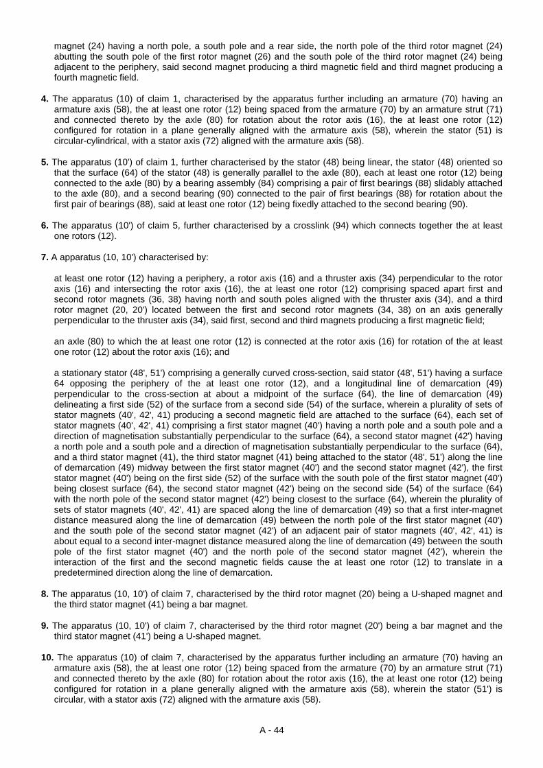
A - 44
magnet (24) having a north pole, a south pole and a rear side, the north pole of the third rotor magnet (24) abutting the south pole of the first rotor magnet (26) and the south pole of the third rotor magnet (24) being adjacent to the periphery, said second magnet producing a third magnetic field and third magnet producing a fourth magnetic field.
4. The apparatus (10) of claim 1, characterised by the apparatus further including an armature (70) having an
armature axis (58), the at least one rotor (12) being spaced from the armature (70) by an armature strut (71) and connected thereto by the axle (80) for rotation about the rotor axis (16), the at least one rotor (12) configured for rotation in a plane generally aligned with the armature axis (58), wherein the stator (51) is circular-cylindrical, with a stator axis (72) aligned with the armature axis (58).
5. The apparatus (10') of claim 1, further characterised by the stator (48) being linear, the stator (48) oriented so
that the surface (64) of the stator (48) is generally parallel to the axle (80), each at least one rotor (12) being connected to the axle (80) by a bearing assembly (84) comprising a pair of first bearings (88) slidably attached to the axle (80), and a second bearing (90) connected to the pair of first bearings (88) for rotation about the first pair of bearings (88), said at least one rotor (12) being fixedly attached to the second bearing (90).
6. The apparatus (10') of claim 5, further characterised by a crosslink (94) which connects together the at least
one rotors (12). 7. A apparatus (10, 10') characterised by:
at least one rotor (12) having a periphery, a rotor axis (16) and a thruster axis (34) perpendicular to the rotor axis (16) and intersecting the rotor axis (16), the at least one rotor (12) comprising spaced apart first and second rotor magnets (36, 38) having north and south poles aligned with the thruster axis (34), and a third rotor magnet (20, 20') located between the first and second rotor magnets (34, 38) on an axis generally perpendicular to the thruster axis (34), said first, second and third magnets producing a first magnetic field; an axle (80) to which the at least one rotor (12) is connected at the rotor axis (16) for rotation of the at least one rotor (12) about the rotor axis (16); and a stationary stator (48', 51') comprising a generally curved cross-section, said stator (48', 51') having a surface 64 opposing the periphery of the at least one rotor (12), and a longitudinal line of demarcation (49) perpendicular to the cross-section at about a midpoint of the surface (64), the line of demarcation (49) delineating a first side (52) of the surface from a second side (54) of the surface, wherein a plurality of sets of stator magnets (40', 42', 41) producing a second magnetic field are attached to the surface (64), each set of stator magnets (40', 42', 41) comprising a first stator magnet (40') having a north pole and a south pole and a direction of magnetisation substantially perpendicular to the surface (64), a second stator magnet (42') having a north pole and a south pole and a direction of magnetisation substantially perpendicular to the surface (64), and a third stator magnet (41), the third stator magnet (41) being attached to the stator (48', 51') along the line of demarcation (49) midway between the first stator magnet (40') and the second stator magnet (42'), the first stator magnet (40') being on the first side (52) of the surface with the south pole of the first stator magnet (40') being closest surface (64), the second stator magnet (42') being on the second side (54) of the surface (64) with the north pole of the second stator magnet (42') being closest to the surface (64), wherein the plurality of sets of stator magnets (40', 42', 41) are spaced along the line of demarcation (49) so that a first inter-magnet distance measured along the line of demarcation (49) between the north pole of the first stator magnet (40') and the south pole of the second stator magnet (42') of an adjacent pair of stator magnets (40', 42', 41) is about equal to a second inter-magnet distance measured along the line of demarcation (49) between the south pole of the first stator magnet (40') and the north pole of the second stator magnet (42'), wherein the interaction of the first and the second magnetic fields cause the at least one rotor (12) to translate in a predetermined direction along the line of demarcation.
8. The apparatus (10, 10') of claim 7, characterised by the third rotor magnet (20) being a U-shaped magnet and
the third stator magnet (41) being a bar magnet. 9. The apparatus (10, 10') of claim 7, characterised by the third rotor magnet (20') being a bar magnet and the
third stator magnet (41') being a U-shaped magnet. 10. The apparatus (10) of claim 7, characterised by the apparatus further including an armature (70) having an
armature axis (58), the at least one rotor (12) being spaced from the armature (70) by an armature strut (71) and connected thereto by the axle (80) for rotation about the rotor axis (16), the at least one rotor (12) being configured for rotation in a plane generally aligned with the armature axis (58), wherein the stator (51') is circular, with a stator axis (72) aligned with the armature axis (58).

A - 45
11. The apparatus (10') of claim 7, further characterised by the stator (48') being linear, the stator (48') oriented so that the surface (64) of the stator (48') is generally parallel to the axle (80), each at least one rotor (12) being connected to the axle (80) by a bearing assembly (84) comprising a pair of first bearings (88) slidably attached to the axle (80), and a second bearing (90) connected to the pair of first bearings (88) for rotation about the pair of first bearings (88), said at least one rotor (12) being fixedly attached to the second bearing (90).
12. The apparatus (10') of claim 11, further characterised by a crosslink (94) which connects together the at least
one rotors (12). 13. An apparatus (10) for providing motion characterised by:
a stationary, generally circular, stator (50, 50', 50'') having a stator axis (58), an outer surface (64), and a circumferential line of demarcation (49) in a plane perpendicular to the stator axis (58) at about a midpoint of the outer surface (64); at least one stator magnet (68, 68', 68'') attached to the outer surface (64) of the stator (50, 50', 50''), the at least one stator magnet (68, 68', 68'') being arranged in a generally circular arrangement about the stator axis (58); an armature (70) attached to the stator (50, 50'', 50'') for rotation therewith, the armature (70) having an axis parallel to the stator axis (58); at least one rotor (12) including at least one rotor magnet (20), the at least one rotor (12) being spaced from the armature (70) by an armature strut (71) and connected thereto by an axle (80) for rotation about a rotor axis (16), the at least one rotor (12) being configured for rotation in a plane generally aligned with the stator axis (58); and a driving linkage assembly (53, 55, 62) connecting the at least one rotor to the stator, the linkage assembly (53, 55, 62) configured to cause the armature (70) to rotate about the stator axis (58) when the at least one rotor (12) rotates about the rotor axis (16).
14. The apparatus according to claim 13 wherein a direction of magnetisation of the at least one stator magnet
(68) is generally perpendicular to a radial line of the at least one rotor (12). 15. The apparatus according to claim 13 wherein a direction of magnetisation of the at least one stator magnet
(68) is generally aligned with a radial line of the at least one rotor (12). 16. The apparatus according to claim 13 wherein the at least one rotor magnet (20) comprises a U-shaped
magnet. 17. The apparatus according to claim 13 wherein the at least one rotor magnet (20) comprises a bar magnet and
the at least one stator magnet (68) is a U-shaped magnet. 18. The apparatus according to claim 13, the at least one stator magnet (68') having a direction of magnetisation
which rotates about the circumferential line of demarcation (49) with a predetermined periodicity. 19. The apparatus according to claim 13, the at least one stator magnet (68'') having a direction of magnetisation
in a plane of the stator (50'') and which is displaced in a sinusoidal pattern from the line of demarcation (49), the sinusoidal pattern having a pre-determined period and a pre-determined maximum amplitude and divided into a plurality of alternating first and second sectors with a boundary between the alternating first and second sectors occurring at peak amplitudes of the sinusoid, the direction of magnetisation of the at least one magnet (68'') being opposite in direction in the first and the second segments.

A - 46
HOWARD JOHNSON: PERMANENT MAGNET MOTOR
Patent US 4,151,431 24th April 1979 Inventor: Howard R. Johnson
PERMANENT MAGNET MOTOR
This is a re-worded extract from this Patent. It describes a motor powered solely by permanent magnets and which it is claimed can power an electrical generator. ABSTRACT The invention is directed to the method of utilising the unpaired electron spins in ferromagnetic and other materials as a source of magnetic fields for producing power without any electron flow as occurs in normal conductors, and to permanent magnet motors for utilising this method to produce a power source. In the practice of the invention the unpaired electron spins occurring within permanent magnets are utilised to produce a motive power source solely through the superconducting characteristics of a permanent magnet, and the magnetic flux created by the magnets is controlled and concentrated to orientate the magnetic forces generated in such a manner to produce useful continuous work, such as the displacement of a rotor with respect to a stator. The timing and orientation of magnetic forces at the rotor and stator components produced by the permanent magnets is accomplished by the proper geometrical relationship of these components. BACKGROUND OF THE INVENTION: Conventional electric motors employ magnetic forces to produce either rotational or linear motion. Electric motors operate on the principal that when a conductor which carries a current is located in a magnetic field, a magnetic force is exerted upon it. Normally, in a conventional electric motor, the rotor, or stator, or both, are so wired that magnetic fields created by electromagnets use attraction, repulsion, or both types of magnetic forces, to impose a force upon the armature causing rotation, or linear displacement of the armature. Conventional electric motors may employ permanent magnets either in the armature or stator components, but to date they require the creation of an electromagnetic field to act upon the permanent magnets. Also, switching gear is needed to control the energising of the electromagnets and the orientation of the magnetic fields producing the motive power. It is my belief that the full potential of magnetic forces existing in permanent magnets has not been recognised or utilised because of incomplete information and theory with respect to atomic motion occurring within a permanent magnet. It is my belief that a presently unnamed atomic particle is associated with the electron movement of a superconducting electromagnet and the loss-less flow of currents in permanent magnets. The unpaired electron flow is similar in both situations. This small particle is believed to be opposite in charge to an electron and to be located at right angles to the moving electron. This particle must be very small to penetrate all known elements in their various states as well as their known compounds (unless they have unpaired electrons which capture these particles as they endeavour to pass through). The electrons in ferrous materials differ from those found in most elements in that they are unpaired, and being unpaired they spin around the nucleus in such a way that they respond to magnetic fields as well as creating a magnetic field themselves. If they were paired, their magnetic fields would cancel out. However, being unpaired they create a measurable magnetic field if their spins are orientated in one direction. The spins are at right angles to their magnetic fields. In niobium superconductors, at a critical state, the magnetic lines of force cease to be at right angles. This change must be due to establishing the required conditions for unpaired electronic spins instead of electron flow in the conductor, and the fact that very powerful electromagnets can be formed with superconductors illustrates the tremendous advantage of producing the magnetic field by unpaired electron spins rather than conventional electron flow. In a superconducting metal, wherein the electrical resistance becomes greater in the metal than the proton resistance, the flow turns to electron spins and the positive particles flow parallel in the metal in the manner occurring in a permanent magnet where a powerful flow of magnetic positive particles or magnetic flux
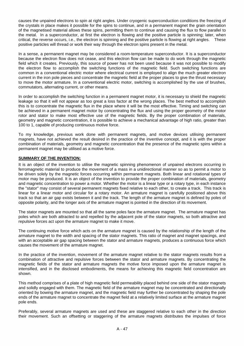
A - 47
causes the unpaired electrons to spin at right angles. Under cryogenic superconduction conditions the freezing of the crystals in place makes it possible for the spins to continue, and in a permanent magnet the grain orientation of the magnetised material allows these spins, permitting them to continue and causing the flux to flow parallel to the metal. In a superconductor, at first the electron is flowing and the positive particle is spinning; later, when critical, the reverse occurs, i.e., the electron is spinning and the positive particle is flowing at right angles. These positive particles will thread or work their way through the electron spins present in the metal. In a sense, a permanent magnet may be considered a room-temperature superconductor. It is a superconductor because the electron flow does not cease, and this electron flow can be made to do work through the magnetic field which it creates. Previously, this source of power has not been used because it was not possible to modify the electron flow to accomplish the switching functions of the magnetic field. Such switching functions are common in a conventional electric motor where electrical current is employed to align the much greater electron current in the iron pole pieces and concentrate the magnetic field at the proper places to give the thrust necessary to move the motor armature. In a conventional electric motor, switching is accomplished by the use of brushes, commutators, alternating current, or other means. In order to accomplish the switching function in a permanent magnet motor, it is necessary to shield the magnetic leakage so that it will not appear as too great a loss factor at the wrong places. The best method to accomplish this is to concentrate the magnetic flux in the place where it will be the most effective. Timing and switching can be achieved in a permanent magnet motor by concentrating the flux and using the proper geometry of the motor rotor and stator to make most effective use of the magnetic fields. By the proper combination of materials, geometry and magnetic concentration, it is possible to achieve a mechanical advantage of high ratio, greater than 100 to 1, capable of producing continuous motive force. To my knowledge, previous work done with permanent magnets, and motive devices utilising permanent magnets, have not achieved the result desired in the practice of the inventive concept, and it is with the proper combination of materials, geometry and magnetic concentration that the presence of the magnetic spins within a permanent magnet may be utilised as a motive force. SUMMARY OF THE INVENTION: It is an object of the invention to utilise the magnetic spinning phenomenon of unpaired electrons occurring in ferromagnetic material to produce the movement of a mass in a unidirectional manner so as to permit a motor to be driven solely by the magnetic forces occurring within permanent magnets. Both linear and rotational types of motor may be produced. It is an object of the invention to provide the proper combination of materials, geometry and magnetic concentration to power a motor. Whether the motor is a linear type or a rotary type, in each instance the "stator" may consist of several permanent magnets fixed relative to each other, to create a track. This track is linear for a linear motor and circular for a rotary motor. An armature magnet is carefully positioned above this track so that an air gap exists between it and the track. The length of the armature magnet is defined by poles of opposite polarity, and the longer axis of the armature magnet is pointed in the direction of its movement. The stator magnets are mounted so that all the same poles face the armature magnet. The armature magnet has poles which are both attracted to and repelled by the adjacent pole of the stator magnets, so both attractive and repulsive forces act upon the armature magnet to make it move. The continuing motive force which acts on the armature magnet is caused by the relationship of the length of the armature magnet to the width and spacing of the stator magnets. This ratio of magnet and magnet spacings, and with an acceptable air gap spacing between the stator and armature magnets, produces a continuous force which causes the movement of the armature magnet. In the practice of the invention, movement of the armature magnet relative to the stator magnets results from a combination of attractive and repulsive forces between the stator and armature magnets. By concentrating the magnetic fields of the stator and armature magnets the motive force imposed upon the armature magnet is intensified, and in the disclosed embodiments, the means for achieving this magnetic field concentration are shown. This method comprises of a plate of high magnetic field permeability placed behind one side of the stator magnets and solidly engaged with them. The magnetic field of the armature magnet may be concentrated and directionally oriented by bowing the armature magnet, and the magnetic field may further be concentrated by shaping the pole ends of the armature magnet to concentrate the magnet field at a relatively limited surface at the armature magnet pole ends. Preferably, several armature magnets are used and these are staggered relative to each other in the direction their movement. Such an offsetting or staggering of the armature magnets distributes the impulses of force

A - 48
imposed upon the armature magnets and results in a smoother application of forces to the armature magnet producing a smoother and more uniform movement of the armature component. In the rotary embodiment of the permanent magnet motor of the invention the stator magnets are arranged in a circle, and the armature magnets rotate about the stator magnets. A mechanism is shown which can move the armature relative to the stator and this controls the magnitude of the magnetic forces, altering the speed of rotation of the motor. BRIEF DESCRIPTION OF THE DRAWINGS The objects and advantages of the invention mentioned earlier, will be appreciated from the following description and accompanying drawings: Fig. 1 is a schematic view of electron flow in a superconductor indicating the unpaired electron spins, Fig. 2 is a cross-sectional view of a superconductor under a critical state illustrating the electron spins, Fig. 3 is a view of a permanent magnet illustrating the flux movement through it, Fig. 4 is a cross-sectional view illustrating the diameter of the magnet of Fig.3, Fig. 5 is an elevational representation of a linear motor embodiment of the permanent magnet motor of the
invention illustrating one position of the armature magnet relative to the stator magnets, and indicating the magnetic forces imposed upon the armature magnet,
Fig. 6 is a view similar to Fig.5 illustrating displacement of the armature magnet relative to the stator magnets, and the influence of magnetic forces thereon at this location,
Fig. 7 is a further elevational view similar to Fig.5 and Fig.6 illustrating further displacement of the armature magnet to the left, and the influence of the magnetic forces thereon,
Fig. 8 is a top plan view of a linear embodiment of the inventive concept illustrating a pair of armature magnets in linked relationship disposed above the stator magnets,
Fig. 9 is a diametrical, elevational, sectional view of a rotary motor embodiment in accord with the invention as taken along section IX-IX of Fig.10, and
Fig. 10 is an elevational view of the rotary motor embodiment as taken along X-X of Fig.9.
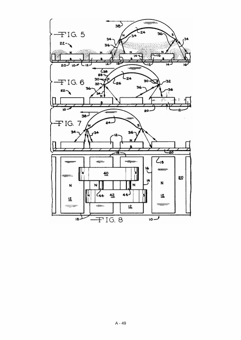
A - 49
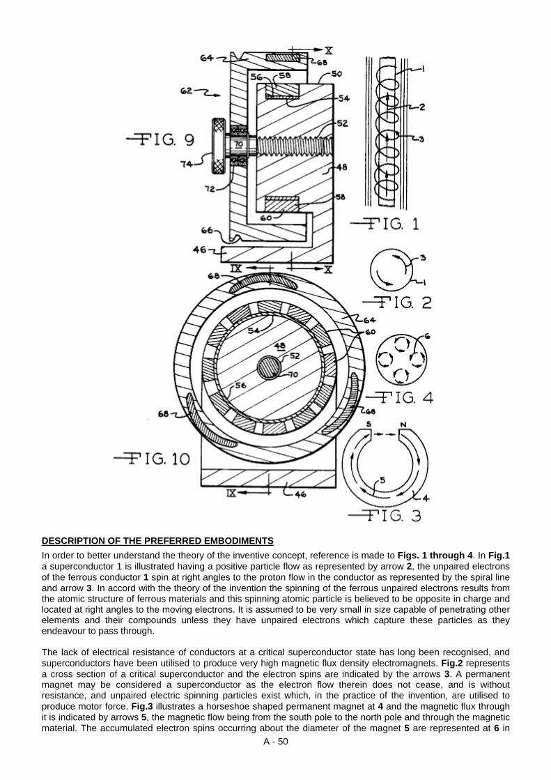
A - 50
DESCRIPTION OF THE PREFERRED EMBODIMENTS In order to better understand the theory of the inventive concept, reference is made to Figs. 1 through 4. In Fig.1 a superconductor 1 is illustrated having a positive particle flow as represented by arrow 2, the unpaired electrons of the ferrous conductor 1 spin at right angles to the proton flow in the conductor as represented by the spiral line and arrow 3. In accord with the theory of the invention the spinning of the ferrous unpaired electrons results from the atomic structure of ferrous materials and this spinning atomic particle is believed to be opposite in charge and located at right angles to the moving electrons. It is assumed to be very small in size capable of penetrating other elements and their compounds unless they have unpaired electrons which capture these particles as they endeavour to pass through. The lack of electrical resistance of conductors at a critical superconductor state has long been recognised, and superconductors have been utilised to produce very high magnetic flux density electromagnets. Fig.2 represents a cross section of a critical superconductor and the electron spins are indicated by the arrows 3. A permanent magnet may be considered a superconductor as the electron flow therein does not cease, and is without resistance, and unpaired electric spinning particles exist which, in the practice of the invention, are utilised to produce motor force. Fig.3 illustrates a horseshoe shaped permanent magnet at 4 and the magnetic flux through it is indicated by arrows 5, the magnetic flow being from the south pole to the north pole and through the magnetic material. The accumulated electron spins occurring about the diameter of the magnet 5 are represented at 6 in
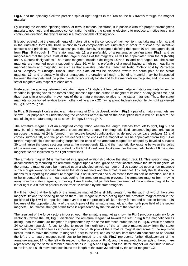
A - 51
Fig.4, and the spinning electron particles spin at right angles in the iron as the flux travels through the magnet material. By utilising the electron spinning theory of ferrous material electrons, it is possible with the proper ferromagnetic materials, geometry and magnetic concentration to utilise the spinning electrons to produce a motive force in a continuous direction, thereby resulting in a motor capable of doing work. It is appreciated that the embodiments of motors utilising the concepts of the invention may take many forms, and in the illustrated forms the basic relationships of components are illustrated in order to disclose the inventive concepts and principles. The relationships of the plurality of magnets defining the stator 10 are best appreciated from Figs. 5 through 8. The stator magnets 12 are preferably of a rectangular configuration, Fig.8, and so magnetised that the poles exist at the large surfaces of the magnets, as will be appreciated from the N (North) and S (South) designations. The stator magnets include side edges 14 and 16 and end edges 18. The stator magnets are mounted upon a supporting plate 20, which is preferably of a metal having a high permeability to magnetic fields and magnetic flux such as that available under the trademark Netic CoNetic sold by Perfection Mica Company of Chicago, Illinois. Thus, the plate 20 will be disposed toward the south pole of the stator magnets 12, and preferably in direct engagement therewith, although a bonding material may be interposed between the magnets and the plate in order to accurately locate and fix the magnets on the plate, and position the stator magnets with respect to each other. Preferably, the spacing between the stator magnets 12 slightly differs between adjacent stator magnets as such a variation in spacing varies the forces being imposed upon the armature magnet at its ends, at any given time, and thus results in a smoother movement of the armature magnet relative to the stator magnets. Thus, the stator magnets so positioned relative to each other define a track 22 having a longitudinal direction left to right as viewed in Figs. 5 through 8. In Figs. 5 through 7 only a single armature magnet 24 is disclosed, while in Fig.8 a pair of armature magnets are shown. For purposes of understanding the concepts of the invention the description herein will be limited to the use of single armature magnet as shown in Figs. 5 through 7. The armature magnet is of an elongated configuration wherein the length extends from left to right, Fig.5, and may be of a rectangular transverse cross-sectional shape. For magnetic field concentrating and orientation purposes the magnet 24 is formed in an arcuate bowed configuration as defined by concave surfaces 26 and convex surfaces 28, and the poles are defined at the ends of the magnet as will be appreciated from Fig.5. For further magnetic field concentrating purposes the ends of the armature magnet are shaped by bevelled surfaces 30 to minimise the cross sectional area at the magnet ends 32, and the magnetic flux existing between the poles of the armature magnet are as indicated by the light dotted lines. In like manner the magnetic fields of 6 the stator magnets 12 are indicated by the light dotted lines. The armature magnet 24 is maintained in a spaced relationship above the stator track 22. This spacing may be accomplished by mounting the armature magnet upon a slide, guide or track located above the stator magnets, or the armature magnet could be mounted upon a wheeled vehicle carriage or slide supported upon a non-magnetic surface or guideway disposed between the stator magnets and the armature magnet. To clarify the illustration, the means for supporting the armature magnet 24 is not illustrated and such means form no part of invention, and it is to be understood that the means supporting the armature magnet prevents the armature magnet from moving away from the stator magnets, or moving closer thereto, but permits free movement of the armature magnet to the left or right in a direction parallel to the track 22 defined by the stator magnets. It will be noted that the length of the armature magnet 24 is slightly greater than the width of two of the stator magnets 12 and the spacing between them. The magnetic forces acting upon the armature magnet when in the position of Fig.5 will be repulsion forces 34 due to the proximity of like polarity forces and attraction forces at 36 because of the opposite polarity of the south pole of the armature magnet, and the north pole field of the sector magnets. The relative strength of this force is represented by the thickness of the force line. The resultant of the force vectors imposed upon the armature magnet as shown in Fig.5 produce a primary force vector 38 toward the left, Fig.5, displacing the armature magnet 24 toward the left. In Fig.6 the magnetic forces acting upon the armature magnet are represented by the same reference numerals as in Fig.5. While the forces 34 constitute repulsion forces tending to move the north pole of the armature magnet away from the stator magnets, the attraction forces imposed upon the south pole of the armature magnet and some of the repulsion forces, tend to move the armature magnet further to the left, and as the resultant force 38 continues to be toward the left the armature magnet continues to be forced to the left. Fig.7 represents further displacement of the armature magnet 24 to the left with respect to the position of Fig.6, and the magnetic forces acting thereon are represented by the same reference numerals as in Fig.5 and Fig.6, and the stator magnet will continue to move to the left, and such movement continues the length of the track 22 defined by the stator magnets 12.
A - 52
Upon the armature magnet being reversed such that the north pole is positioned at the right as viewed in Fig.5, and the south pole is positioned at the left, the direction of movement of the armature magnet relative to the stator magnets is toward the right, and the theory of movement is identical to that described above. In Fig.8 a plurality of armature magnets 40 and 42 are illustrated which are connected by links 44. The armature magnets are of a shape and configuration identical to that of the embodiment of Fig.5, but the magnets are staggered with respect to each other in the direction of magnet movement, i.e., the direction of the track 22 defined by the stator magnets 12. By so staggering a plurality of armature magnets a smoother movement of the interconnected armature magnets is produced as compared when using a single armature magnet as there is variation in the forces acting upon each armature magnet as it moves above the track 22 due to the change in magnetic forces imposed thereon. The use of several armature magnets tends to "smooth out" the application of forces imposed upon linked armature magnets, resulting in a smoother movement of the armature magnet assembly. Of course, any number of armature magnets may be interconnected, limited only by the width of the stator magnet track 22. In Fig.9 and Fig.10 a rotary embodiment embracing the inventive concepts is illustrated. In this embodiment the principle of operation is identical to that described above, but the orientation of the stator and armature magnets is such that rotation of the armature magnets is produced about an axis, rather than a linear movement being achieved. In Fig.9 and Fig.10 a base is represented at 46 serving as a support for a stator member 48. The stator member 48 is made of a non-magnetic material, such as synthetic plastic, aluminium, or the like. The stator includes a cylindrical surface 50 having an axis, and a threaded bore 52 is concentrically defined in the stator. The stator includes an annular groove 54 receiving an annular sleeve 56 of high magnetic field permeability material such as Netic Co-Netic and a plurality of stator magnets 58 are affixed upon the sleeve 56 in spaced circumferential relationship as will be apparent in Fig.10. Preferably, the stator magnets 58 are formed with converging radial sides as to be of a wedge configuration having a curved inner surface engaging sleeve 56, and a convex pole surface 60. The armature 62, in the illustrated embodiment, is of a dished configuration having a radial web portion, and an axially extending portion 64. The armature 62 is formed of a non-magnetic material, and an annular belt receiving groove 66 is defined therein for receiving a belt for transmitting power from the armature to a generator, or other power consuming device. Three armature magnets 68 are mounted on the armature portion 64, and such magnets are of a configuration similar to the armature magnet configuration of Figs. 5 through 7. The magnets 68 are staggered with respect to each other in a circumferential direction wherein the magnets are not placed exactly 120 degrees apart but instead, a slight angular staggering of the armature magnets is desirable to "smooth out" the magnetic forces being imposed upon the armature as a result of the magnetic forces being simultaneously imposed upon each of the armature magnets. The staggering of the armature magnets 68 in a circumferential direction produces the same effect as the staggering of the armature magnets 40 and 42 as shown in Fig.8. The armature 62 is mounted upon a threaded shaft 70 by anti-friction bearings 72, and the shaft 70 is threaded into the stator threaded bore 52, and may be rotated by the knob 74. In this manner rotation of the knob 74, and shaft 70, axially displaces the armature 62 with respect to the stator magnets 58, and such axial displacement will very the magnitude of the magnetic forces imposed upon the armature magnets 68 by the stator magnets thereby controlling the speed of rotation of the armature. As will be noted from Figs. 4 to 7, 9 and 10, an air gap exists between the armature magnets and the stator magnets and the dimension of this spacing, effects the magnitude of the forces imposed upon the armature magnet or magnets. If the distance between the armature magnets and the stator magnets is reduced the forces imposed upon the armature magnets by the stator magnets are increased, and the resultant force 8 vector tending to displace the armature magnets in their path of movement increases. However, the decreasing of the spacing between the armature and stator magnets creates a "pulsation" in the movement of the armature magnets which is objectionable, but can be, to some extent, minimised by using a plurality of armature magnets. Increasing the distance between the armature and stator magnets reduces the pulsation tendency of the armature magnet, but also reduces the magnitude of the magnetic forces imposed upon the armature magnets. Thus, the most effective spacing between the armature and stator magnets is that spacing which produces the maximum force vector in the direction of armature magnet movement, with a minimum creation of objectionable pulsation. In the disclosed embodiments the high permeability plate 20 and sleeve 56 are disclosed for concentrating the magnetic field of the stator magnets, and the armature magnets are bowed and have shaped ends for magnetic field concentration purposes. While such magnetic field concentration means result in higher forces imposed upon
A - 53
the armature magnets for given magnet intensities, it is not intended that the inventive concepts be limited to the use of such magnetic field concentrating means. As will be appreciated from the above description of the invention, the movement of the armature magnet or magnets results from the described relationship of components. The length of the armature magnets as related to the width of the stator magnets and spacing between them, the dimension of the air gap and the configuration of the magnetic field, combined, produce the desired result and motion. The inventive concepts may be practised even though these relationships may be varied within limits not yet defined and the invention is intended to encompass all dimensional relationships which achieve the desired goal of armature movement. By way of example, with respect to Figs. to 7, the following dimensions were used in an operating prototype: The length of armature magnet 24 is 3.125", the stator magnets 12 are 1" wide, .25" thick and 4" long and grain oriented. The air gap between the poles of the armature magnet and the stator magnets is approximately 1.5" and the spacing between the stator magnets is approximately .5" inch. In effect, the stator magnets define a magnetic field track of a single polarity transversely interrupted at spaced locations by the magnetic fields produced by the lines of force existing between the poles of the stator magnets and the unidirectional force exerted on the armature magnet is a result of the repulsion and attraction forces existing as the armature magnet traverses this magnetic field track. It is to be understood that the inventive concept embraces an arrangement wherein the armature magnet component is stationary and the stator assembly is supported for movement and constitutes the moving component, and other variations of the inventive concept will be apparent to those skilled in the art without departing from the scope thereof. As used herein the term "track" is intended to include both linear and circular arrangements of the static magnets, and the "direction" or "length" of the track is that direction parallel or concentric to the intended direction of armature magnet movement. CLAIMS 1. A permanent magnet motor comprising, in combination, a stator track defining a track direction and having first
and second sides and composed of a plurality of track permanent magnets each having first and second poles of opposite polarity, said magnets being disposed in side-by-side relationship having a spacing between adjacent magnets and like poles defining said track sides, an elongated armature permanent magnet located on one of said track sides for relative movement thereto and in spaced relationship to said track side wherein an air gap exists between said armature magnet and said track magnets, said armature magnet having first and second poles of opposite polarity located at the opposite ends of said armature magnet deeming the length thereof, the length of said armature magnet being disposed in a direction in general alignment with the direction of said track, the spacing of said armature magnet poles from said track associated side and the length of said armature magnet as related to the width and spacing of said track magnets in the direction of said track being such as to impose a continuous force on said armature magnet in said general direction of said track.
2. In a permanent magnet motor as in claim 1 wherein the spacing between said poles of said armature and the
adjacent stator track side are substantially equal. 3. In a permanent magnet motor as in claim 1 wherein the spacing between adjacent track magnets varies. 4. In a permanent magnet motor as in claim 1 wherein a plurality of armature magnets are disposed on a common
side of said stator track, said armature magnets being mechanically interconnected. 5. In a permanent magnet motor as in claim 4 wherein said armature magnets are staggered with respect to each
other in the direction of said track. 6. In a permanent magnet motor as in claim 1 wherein magnetic field concentrating means are associated with
said track magnets. 7. In a permanent magnet motor as in claim 6 wherein said field concentrating means comprises a sheet of
magnetic material of high field permeability engaging side and pole of said track opposite to that side and pole disposed toward said armature magnet.
8. In a permanent magnet as in claim 1 wherein said armature magnet is of an arcuate configuration in its
longitudinal direction bowed toward said track, said armature magnet having ends shaped to concentrate the magnetic field at said ends.
A - 54
9. In a permanent magnet motor as in claim 1 wherein said stator track is of a generally linear configuration, and means supporting said armature magnet relative to said track for generally linear movement of said armature magnet.
10. In a permanent magnet motor as in claim 1 wherein said stator track magnets define a circle having an axis,
an armature rotatably mounted with respect to said track and concentric and coaxial thereto, said armature magnet being mounted upon said armature.
11. In a permanent magnet motor as in claim 10, means axially adjusting said armature relative to said track
whereby the axial relationship of said armature magnet and said stator magnets may be varied to adjust the rate of rotation of said armature.
12. In a permanent magnet motor as in claim 10 wherein a plurality of armature magnets are mounted on said
armature. 13. In a permanent magnet motor as in claim 12 wherein said armature magnets are circumferentially non-
uniformly spaced on said armature. 14. A permanent magnet motor comprising, in combination, a stator comprising a plurality of circumferentially
spaced stator permanent magnets having poles of opposite polarity, said magnets being arranged to substantially define a circle having an axis, the poles of said magnets facing in a radial direction with respect to said axis and poles of the same polarity facing away from said axis and the poles of opposite polarity facing toward said axis, an armature mounted for rotation about said axis and disposed adjacent said stator, at least one armature permanent magnet having poles of opposite polarity mounted on said armature and in radial spaced relationship to said circle of stator magnets, said armature magnet poles extending in the circumferential direction of armature rotation, the spacing of said armature magnet poles from said stator magnets and the circumferential length of said armature magnet and the spacing of said stator magnets being such as to impose a continuing circumferential force on said armature magnet to rotate said armature.
15. In a permanent magnet motor as in claim 14 wherein a plurality of armature magnets are mounted upon said
armature. 16. In a permanent magnet motor as in claim 14 wherein said armature magnets are asymmetrically
circumferentially spaced on said armature. 17. In a permanent magnet motor as in claim 14 wherein the poles of said armature magnet are shaped to
concentrate the magnetic field thereof. 18. In a permanent magnet motor as in claim 14, magnetic field concentrating means associated with said stator
magnets concentrating the magnetic fields thereof at the spacings between adjacent stator magnets. 19. In a permanent magnet motor as in claim 18 wherein said magnet field concentrating means comprises an
annular ring of high magnetic field permeability material concentric with said axis and in substantial engagement with poles of like polarity of said stator magnets.
20. In a permanent magnet motor as in claim 14 wherein said armature magnet is of an arcuate bowed
configuration in the direction of said poles thereof defining a concave side and a convex side, said concave side being disposed toward said axis, and said poles of said armature magnet being shaped to concentrate the magnetic field between said poles thereof.
21. In a permanent magnet motor as in claim 14, means for axially displacing said stator and armature relative to
each other to adjust the axial alignment of said stator and armature magnets. 22. The method of producing a unidirectional motive force by permanent magnets using a plurality of spaced
stator permanent magnets having opposite polarity poles defining a track having a predetermined direction, and an armature magnet having a length defined by poles of opposite polarity movably mounted for movement relative to the track in the direction thereof, and of a predetermined length determined by the width and dimensions of said stator magnets comprising forming a magnetic field track by said stator magnets having a magnetic field of common polarity interrupted at spaced locations in a direction transverse to the direction of said magnetic field track by magnetic fields created by magnetic lines of force existing between the poles of the stator magnets and positioning the armature magnet in spaced relation to said magnetic field track longitudinally related to the direction of the magnetic field track such a distance that the repulsion and attraction forces imposed on the armature magnet by said magnetic field track imposes a continuing unidirectional force on the armature magnet in the direction of the magnetic field track.
A - 55
23. The method of producing a unidirectional motive force as in claim 22 including concentrating the magnetic fields created by magnetic lines of force between the poles of the stator magnets.
24. The method of producing a unidirectional motive force as in claim 22 including concentrating the magnetic
field existing between the poles of the armature magnet. 25. The method of producing a unidirectional motive force as in claim 22 including concentrating the magnetic
fields created by magnetic lines of force between the poles of the stator magnets and concentrating the 12 magnetic field existing between the poles of the armature magnet.
26. The method of producing a motive force by permanent magnets wherein the unpaired electron spinning
particles existing within a permanent magnet are utilised for producing a motive force comprising forming a stator magnetic field track by means of at least one permanent magnet, producing an armature magnetic field by means of a permanent magnet and shaping and locating said magnetic fields in such a manner as to produce relative continuous unidirectional motion between said stator and armature field producing magnets.
27. The method of producing a motive force by permanent magnets as in claim 26 wherein said stator magnetic
field is substantially of a single polarity. 28. The method of producing a motive force by permanent magnets as in claim 26 including concentrating the
magnetic field of said stator field track and armature magnetic field.
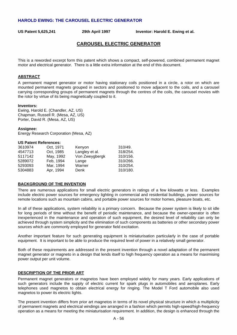
A - 56
HAROLD EWING: THE CAROUSEL ELECTRIC GENERATOR US Patent 5,625,241 29th April 1997 Inventor: Harold E. Ewing et al.
CAROUSEL ELECTRIC GENERATOR
This is a reworded excerpt form this patent which shows a compact, self-powered, combined permanent magnet motor and electrical generator. There is a little extra information at the end of this document.
ABSTRACT A permanent magnet generator or motor having stationary coils positioned in a circle, a rotor on which are mounted permanent magnets grouped in sectors and positioned to move adjacent to the coils, and a carousel carrying corresponding groups of permanent magnets through the centres of the coils, the carousel movies with the rotor by virtue of its being magnetically coupled to it. Inventors: Ewing, Harold E. (Chandler, AZ, US) Chapman, Russell R. (Mesa, AZ, US) Porter, David R. (Mesa, AZ, US) Assignee: Energy Research Corporation (Mesa, AZ) US Patent References: 3610974 Oct, 1971 Kenyon 310/49. 4547713 Oct, 1985 Langley et al. 318/254. 5117142 May, 1992 Von Zweygbergk 310/156. 5289072 Feb, 1994 Lange 310/266. 5293093 Mar, 1994 Warner 310/254. 5304883 Apr, 1994 Denk 310/180. BACKGROUND OF THE INVENTION There are numerous applications for small electric generators in ratings of a few kilowatts or less. Examples include electric power sources for emergency lighting in commercial and residential buildings, power sources for remote locations such as mountain cabins, and portable power sources for motor homes, pleasure boats, etc. In all of these applications, system reliability is a primary concern. Because the power system is likely to sit idle for long periods of time without the benefit of periodic maintenance, and because the owner-operator is often inexperienced in the maintenance and operation of such equipment, the desired level of reliability can only be achieved through system simplicity and the elimination of such components as batteries or other secondary power sources which are commonly employed for generator field excitation. Another important feature for such generating equipment is miniaturisation particularly in the case of portable equipment. It is important to be able to produce the required level of power in a relatively small generator. Both of these requirements are addressed in the present invention through a novel adaptation of the permanent magnet generator or magneto in a design that lends itself to high frequency operation as a means for maximising power output per unit volume. DESCRIPTION OF THE PRIOR ART Permanent magnet generators or magnetos have been employed widely for many years. Early applications of such generators include the supply of electric current for spark plugs in automobiles and aeroplanes. Early telephones used magnetos to obtain electrical energy for ringing. The Model T Ford automobile also used magnetos to power its electric lights. The present invention differs from prior art magnetos in terms of its novel physical structure in which a multiplicity of permanent magnets and electrical windings are arranged in a fashion which permits high-speed/high-frequency operation as a means for meeting the miniaturisation requirement. In addition, the design is enhanced through the
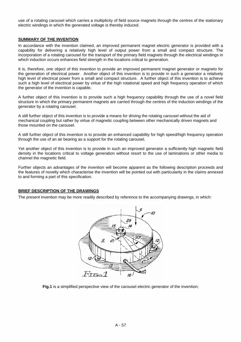
A - 57
use of a rotating carousel which carries a multiplicity of field source magnets through the centres of the stationary electric windings in which the generated voltage is thereby induced. SUMMARY OF THE INVENTION In accordance with the invention claimed, an improved permanent magnet electric generator is provided with a capability for delivering a relatively high level of output power from a small and compact structure. The incorporation of a rotating carousel for the transport of the primary field magnets through the electrical windings in which induction occurs enhances field strength in the locations critical to generation. It is, therefore, one object of this invention to provide an improved permanent magnet generator or magneto for the generation of electrical power. Another object of this invention is to provide in such a generator a relatively high level of electrical power from a small and compact structure. A further object of this invention is to achieve such a high level of electrical power by virtue of the high rotational speed and high frequency operation of which the generator of the invention is capable. A further object of this invention is to provide such a high frequency capability through the use of a novel field structure in which the primary permanent magnets are carried through the centres of the induction windings of the generator by a rotating carousel. A still further object of this invention is to provide a means for driving the rotating carousel without the aid of mechanical coupling but rather by virtue of magnetic coupling between other mechanically driven magnets and those mounted on the carousel. A still further object of this invention is to provide an enhanced capability for high speed/high frequency operation through the use of an air bearing as a support for the rotating carousel. Yet another object of this invention is to provide in such an improved generator a sufficiently high magnetic field density in the locations critical to voltage generation without resort to the use of laminations or other media to channel the magnetic field. Further objects an advantages of the invention will become apparent as the following description proceeds and the features of novelty which characterise the invention will be pointed out with particularity in the claims annexed to and forming a part of this specification. BRIEF DESCRIPTION OF THE DRAWINGS The present invention may be more readily described by reference to the accompanying drawings, in which:
Fig.1 is a simplified perspective view of the carousel electric generator of the invention;
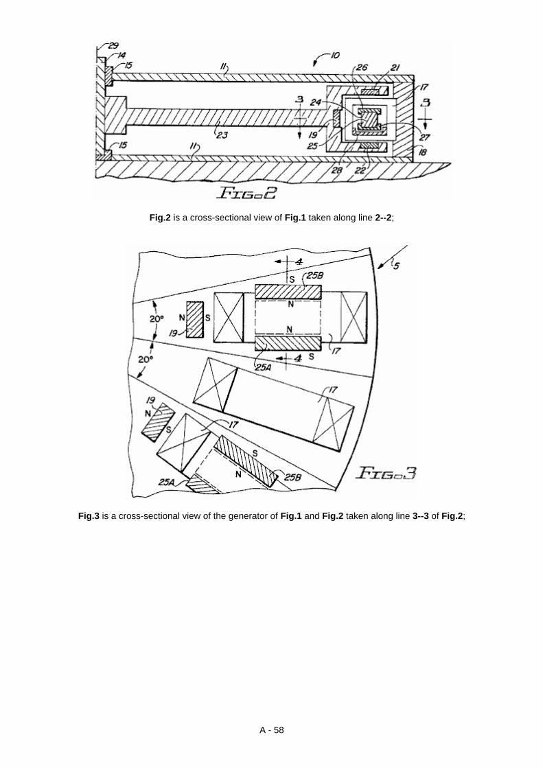
A - 58
Fig.2 is a cross-sectional view of Fig.1 taken along line 2--2;
Fig.3 is a cross-sectional view of the generator of Fig.1 and Fig.2 taken along line 3--3 of Fig.2;
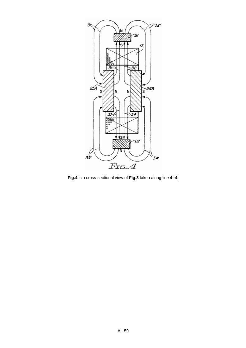
A - 59
Fig.4 is a cross-sectional view of Fig.3 taken along line 4--4;
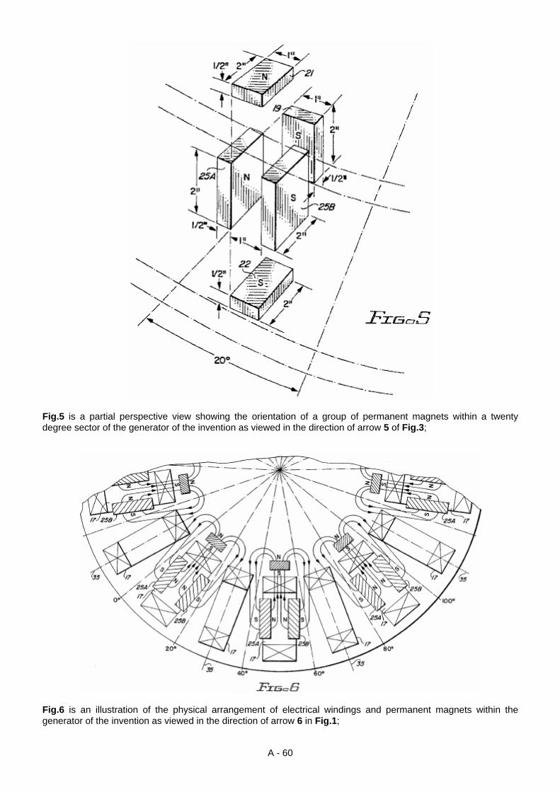
A - 60
Fig.5 is a partial perspective view showing the orientation of a group of permanent magnets within a twenty degree sector of the generator of the invention as viewed in the direction of arrow 5 of Fig.3;
Fig.6 is an illustration of the physical arrangement of electrical windings and permanent magnets within the generator of the invention as viewed in the direction of arrow 6 in Fig.1;
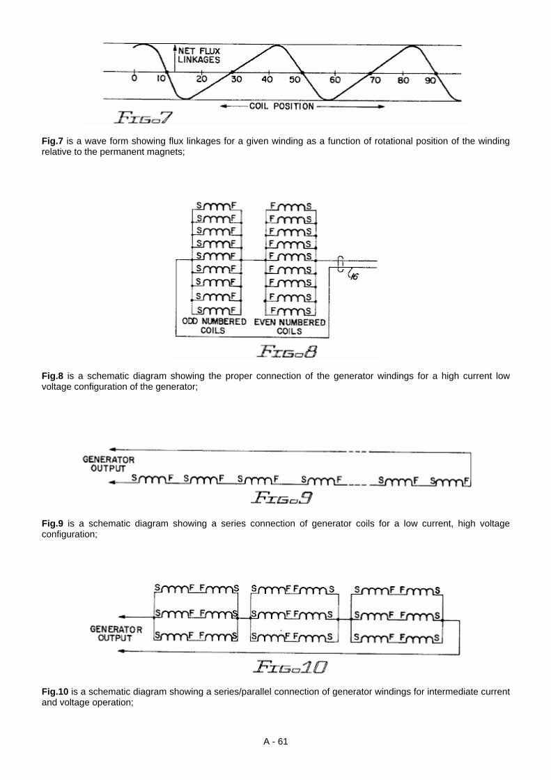
A - 61
Fig.7 is a wave form showing flux linkages for a given winding as a function of rotational position of the winding relative to the permanent magnets;
Fig.8 is a schematic diagram showing the proper connection of the generator windings for a high current low voltage configuration of the generator;
Fig.9 is a schematic diagram showing a series connection of generator coils for a low current, high voltage configuration;
Fig.10 is a schematic diagram showing a series/parallel connection of generator windings for intermediate current and voltage operation;

A - 62
Fig.11 is a perspective presentation of a modified carousel magnet configuration employed in a second embodiment of the invention;
Fig.12A and Fig.12B show upper and lower views of the carousel magnets of Fig.11;
Fig.13 is a cross-sectional view of the modified magnet configuration of Fig.11 taken along line 13--13 with other features of the modified carousel structure also shown;
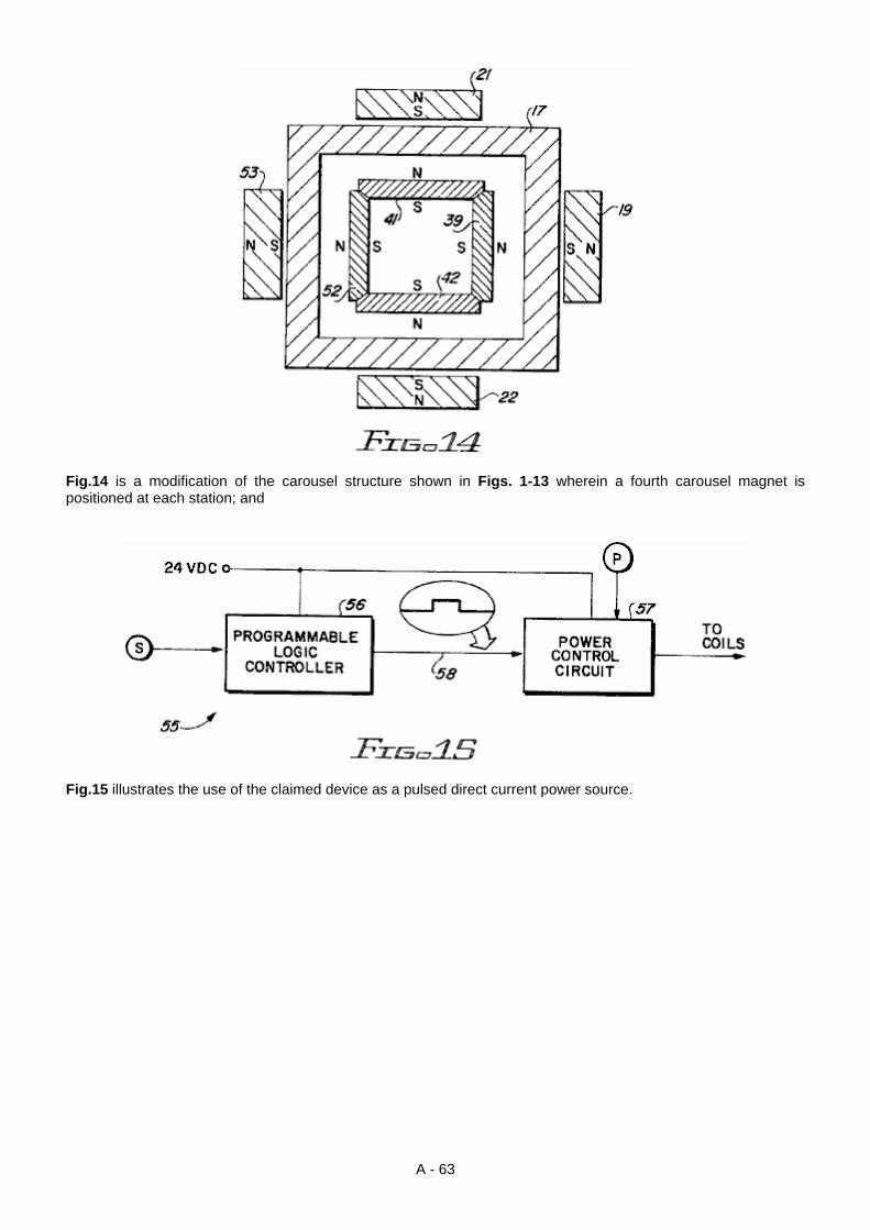
A - 63
Fig.14 is a modification of the carousel structure shown in Figs. 1-13 wherein a fourth carousel magnet is positioned at each station; and
Fig.15 illustrates the use of the claimed device as a pulsed direct current power source.

A - 64
DESCRIPTION OF THE PREFERRED EMBODIMENT
Referring more particularly to the drawings by characters of reference, Fig.1 shows the external proportions of a carousel electric generator 10 of the invention. As shown in Fig.1, generator 10 is enclosed by a housing 11 with mounting feet 12 suitable for securing the generator to a flat surface 13. The surface 13 is preferably horizontal, as shown in Fig.1. Housing 11 has the proportions of a short cylinder. A drive shaft 14 extends axially from housing 11 through a bearing 15. The electrical output of the generator is brought out through a cable 16.
The cross-sectional view of Fig.2 shows the active elements incorporated in one twenty degree sector of the stator and in one twenty degree sector of the rotor. In the first implementation of the invention, there are eighteen identical stator sectors, each incorporating a winding or coil 17 wound about a rectangular coil frame or bobbin. Coil 17 is held by a stator frame 18 which may also serve as an outer wall of frame 11. The rotor is also divided into eighteen sectors, nine of which incorporate three permanent magnets each, including an inboard rotor magnet 19, an upper rotor magnet 21 and a lower rotor magnet 22. All three of these magnets have their south poles facing coil 17, and all three are mounted directly on rotor frame 23 which is secured directly to drive shaft 14. The other nine sectors of the rotor are empty, i.e. they are not populated with magnets. The unpopulated sectors are alternated with the populated sectors so that adjacent populated sectors are separated by an unpopulated sector as shown in Fig.3 and Fig.6. With reference again to Fig.2, generator 10 also incorporates a carousel 24. The carousel comprises nine pairs of carousel magnets 25 clamped between upper and lower retainer rings 26 and 27, respectively. The lower retainer ring 27 rests inside an air bearing channel 28 which is secured to stator 18 inside the bobbin of coil 17. Air passages (not shown) admit air into the space between the lower surface of ring 27 and the upper or inside
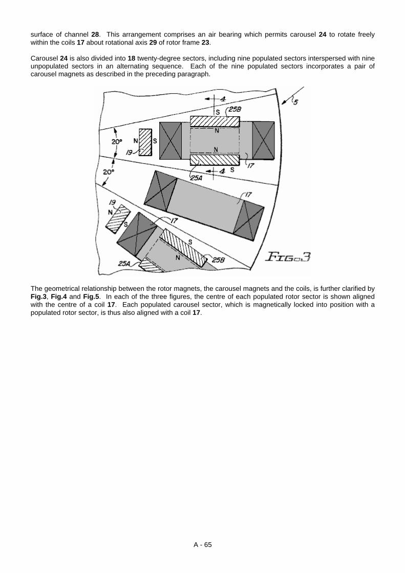
A - 65
surface of channel 28. This arrangement comprises an air bearing which permits carousel 24 to rotate freely within the coils 17 about rotational axis 29 of rotor frame 23. Carousel 24 is also divided into 18 twenty-degree sectors, including nine populated sectors interspersed with nine unpopulated sectors in an alternating sequence. Each of the nine populated sectors incorporates a pair of carousel magnets as described in the preceding paragraph.
The geometrical relationship between the rotor magnets, the carousel magnets and the coils, is further clarified by Fig.3, Fig.4 and Fig.5. In each of the three figures, the centre of each populated rotor sector is shown aligned with the centre of a coil 17. Each populated carousel sector, which is magnetically locked into position with a populated rotor sector, is thus also aligned with a coil 17.
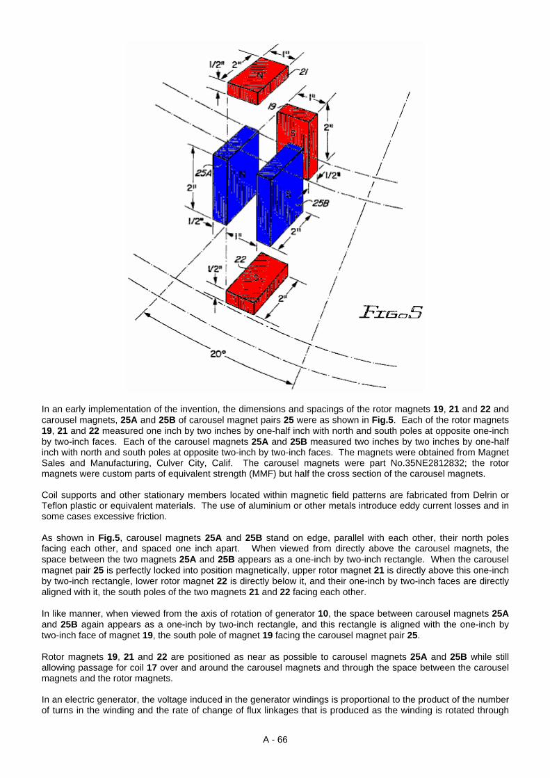
A - 66
In an early implementation of the invention, the dimensions and spacings of the rotor magnets 19, 21 and 22 and carousel magnets, 25A and 25B of carousel magnet pairs 25 were as shown in Fig.5. Each of the rotor magnets 19, 21 and 22 measured one inch by two inches by one-half inch with north and south poles at opposite one-inch by two-inch faces. Each of the carousel magnets 25A and 25B measured two inches by two inches by one-half inch with north and south poles at opposite two-inch by two-inch faces. The magnets were obtained from Magnet Sales and Manufacturing, Culver City, Calif. The carousel magnets were part No.35NE2812832; the rotor magnets were custom parts of equivalent strength (MMF) but half the cross section of the carousel magnets. Coil supports and other stationary members located within magnetic field patterns are fabricated from Delrin or Teflon plastic or equivalent materials. The use of aluminium or other metals introduce eddy current losses and in some cases excessive friction. As shown in Fig.5, carousel magnets 25A and 25B stand on edge, parallel with each other, their north poles facing each other, and spaced one inch apart. When viewed from directly above the carousel magnets, the space between the two magnets 25A and 25B appears as a one-inch by two-inch rectangle. When the carousel magnet pair 25 is perfectly locked into position magnetically, upper rotor magnet 21 is directly above this one-inch by two-inch rectangle, lower rotor magnet 22 is directly below it, and their one-inch by two-inch faces are directly aligned with it, the south poles of the two magnets 21 and 22 facing each other. In like manner, when viewed from the axis of rotation of generator 10, the space between carousel magnets 25A and 25B again appears as a one-inch by two-inch rectangle, and this rectangle is aligned with the one-inch by two-inch face of magnet 19, the south pole of magnet 19 facing the carousel magnet pair 25. Rotor magnets 19, 21 and 22 are positioned as near as possible to carousel magnets 25A and 25B while still allowing passage for coil 17 over and around the carousel magnets and through the space between the carousel magnets and the rotor magnets. In an electric generator, the voltage induced in the generator windings is proportional to the product of the number of turns in the winding and the rate of change of flux linkages that is produced as the winding is rotated through
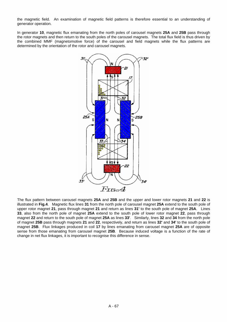
A - 67
the magnetic field. An examination of magnetic field patterns is therefore essential to an understanding of generator operation. In generator 10, magnetic flux emanating from the north poles of carousel magnets 25A and 25B pass through the rotor magnets and then return to the south poles of the carousel magnets. The total flux field is thus driven by the combined MMF (magnetomotive force) of the carousel and field magnets while the flux patterns are determined by the orientation of the rotor and carousel magnets.
The flux pattern between carousel magnets 25A and 25B and the upper and lower rotor magnets 21 and 22 is illustrated in Fig.4. Magnetic flux lines 31 from the north pole of carousel magnet 25A extend to the south pole of upper rotor magnet 21, pass through magnet 21 and return as lines 31' to the south pole of magnet 25A. Lines 33, also from the north pole of magnet 25A extend to the south pole of lower rotor magnet 22, pass through magnet 22 and return to the south pole of magnet 25A as lines 33'. Similarly, lines 32 and 34 from the north pole of magnet 25B pass through magnets 21 and 22, respectively, and return as lines 32' and 34' to the south pole of magnet 25B. Flux linkages produced in coil 17 by lines emanating from carousel magnet 25A are of opposite sense from those emanating from carousel magnet 25B. Because induced voltage is a function of the rate of change in net flux linkages, it is important to recognise this difference in sense.
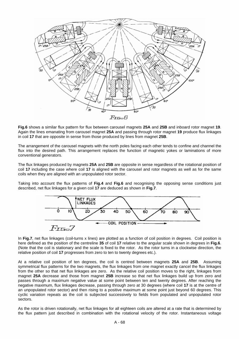
A - 68
Fig.6 shows a similar flux pattern for flux between carousel magnets 25A and 25B and inboard rotor magnet 19. Again the lines emanating from carousel magnet 25A and passing through rotor magnet 19 produce flux linkages in coil 17 that are opposite in sense from those produced by lines from magnet 25B. The arrangement of the carousel magnets with the north poles facing each other tends to confine and channel the flux into the desired path. This arrangement replaces the function of magnetic yokes or laminations of more conventional generators. The flux linkages produced by magnets 25A and 25B are opposite in sense regardless of the rotational position of coil 17 including the case where coil 17 is aligned with the carousel and rotor magnets as well as for the same coils when they are aligned with an unpopulated rotor sector. Taking into account the flux patterns of Fig.4 and Fig.6 and recognising the opposing sense conditions just described, net flux linkages for a given coil 17 are deduced as shown in Fig.7.
In Fig.7, net flux linkages (coil-turns x lines) are plotted as a function of coil position in degrees. Coil position is here defined as the position of the centreline 35 of coil 17 relative to the angular scale shown in degrees in Fig.6. (Note that the coil is stationary and the scale is fixed to the rotor. As the rotor turns in a clockwise direction, the relative position of coil 17 progresses from zero to ten to twenty degrees etc.). At a relative coil position of ten degrees, the coil is centred between magnets 25A and 25B. Assuming symmetrical flux patterns for the two magnets, the flux linkages from one magnet exactly cancel the flux linkages from the other so that net flux linkages are zero. As the relative coil position moves to the right, linkages from magnet 25A decrease and those from magnet 25B increase so that net flux linkages build up from zero and passes through a maximum negative value at some point between ten and twenty degrees. After reaching the negative maximum, flux linkages decrease, passing through zero at 30 degrees (where coil 17 is at the centre of an unpopulated rotor sector) and then rising to a positive maximum at some point just beyond 60 degrees. This cyclic variation repeats as the coil is subjected successively to fields from populated and unpopulated rotor sectors. As the rotor is driven rotationally, net flux linkages for all eighteen coils are altered at a rate that is determined by the flux pattern just described in combination with the rotational velocity of the rotor. Instantaneous voltage
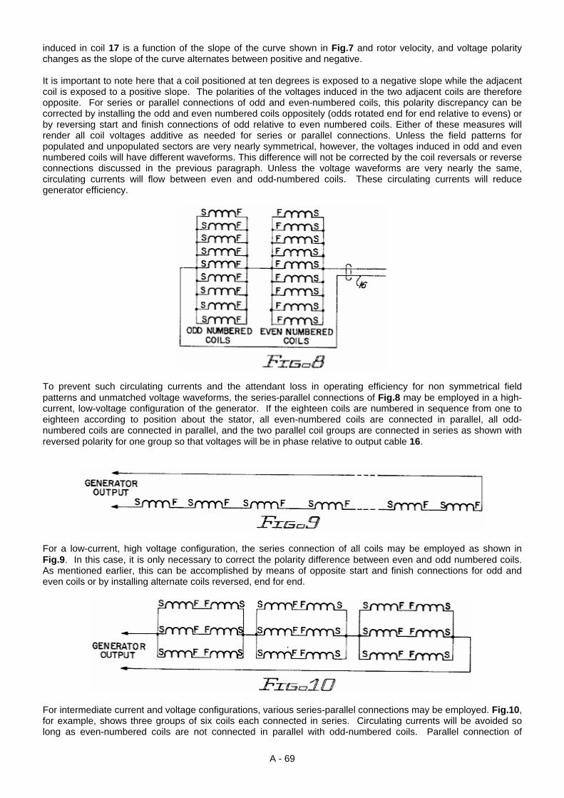
A - 69
induced in coil 17 is a function of the slope of the curve shown in Fig.7 and rotor velocity, and voltage polarity changes as the slope of the curve alternates between positive and negative. It is important to note here that a coil positioned at ten degrees is exposed to a negative slope while the adjacent coil is exposed to a positive slope. The polarities of the voltages induced in the two adjacent coils are therefore opposite. For series or parallel connections of odd and even-numbered coils, this polarity discrepancy can be corrected by installing the odd and even numbered coils oppositely (odds rotated end for end relative to evens) or by reversing start and finish connections of odd relative to even numbered coils. Either of these measures will render all coil voltages additive as needed for series or parallel connections. Unless the field patterns for populated and unpopulated sectors are very nearly symmetrical, however, the voltages induced in odd and even numbered coils will have different waveforms. This difference will not be corrected by the coil reversals or reverse connections discussed in the previous paragraph. Unless the voltage waveforms are very nearly the same, circulating currents will flow between even and odd-numbered coils. These circulating currents will reduce generator efficiency.
To prevent such circulating currents and the attendant loss in operating efficiency for non symmetrical field patterns and unmatched voltage waveforms, the series-parallel connections of Fig.8 may be employed in a high-current, low-voltage configuration of the generator. If the eighteen coils are numbered in sequence from one to eighteen according to position about the stator, all even-numbered coils are connected in parallel, all odd-numbered coils are connected in parallel, and the two parallel coil groups are connected in series as shown with reversed polarity for one group so that voltages will be in phase relative to output cable 16.
For a low-current, high voltage configuration, the series connection of all coils may be employed as shown in Fig.9. In this case, it is only necessary to correct the polarity difference between even and odd numbered coils. As mentioned earlier, this can be accomplished by means of opposite start and finish connections for odd and even coils or by installing alternate coils reversed, end for end.
For intermediate current and voltage configurations, various series-parallel connections may be employed. Fig.10, for example, shows three groups of six coils each connected in series. Circulating currents will be avoided so long as even-numbered coils are not connected in parallel with odd-numbered coils. Parallel connection of
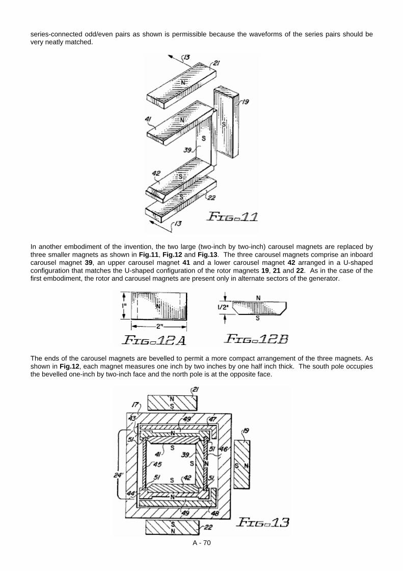
A - 70
series-connected odd/even pairs as shown is permissible because the waveforms of the series pairs should be very neatly matched.
In another embodiment of the invention, the two large (two-inch by two-inch) carousel magnets are replaced by three smaller magnets as shown in Fig.11, Fig.12 and Fig.13. The three carousel magnets comprise an inboard carousel magnet 39, an upper carousel magnet 41 and a lower carousel magnet 42 arranged in a U-shaped configuration that matches the U-shaped configuration of the rotor magnets 19, 21 and 22. As in the case of the first embodiment, the rotor and carousel magnets are present only in alternate sectors of the generator.
The ends of the carousel magnets are bevelled to permit a more compact arrangement of the three magnets. As shown in Fig.12, each magnet measures one inch by two inches by one half inch thick. The south pole occupies the bevelled one-inch by two-inch face and the north pole is at the opposite face.
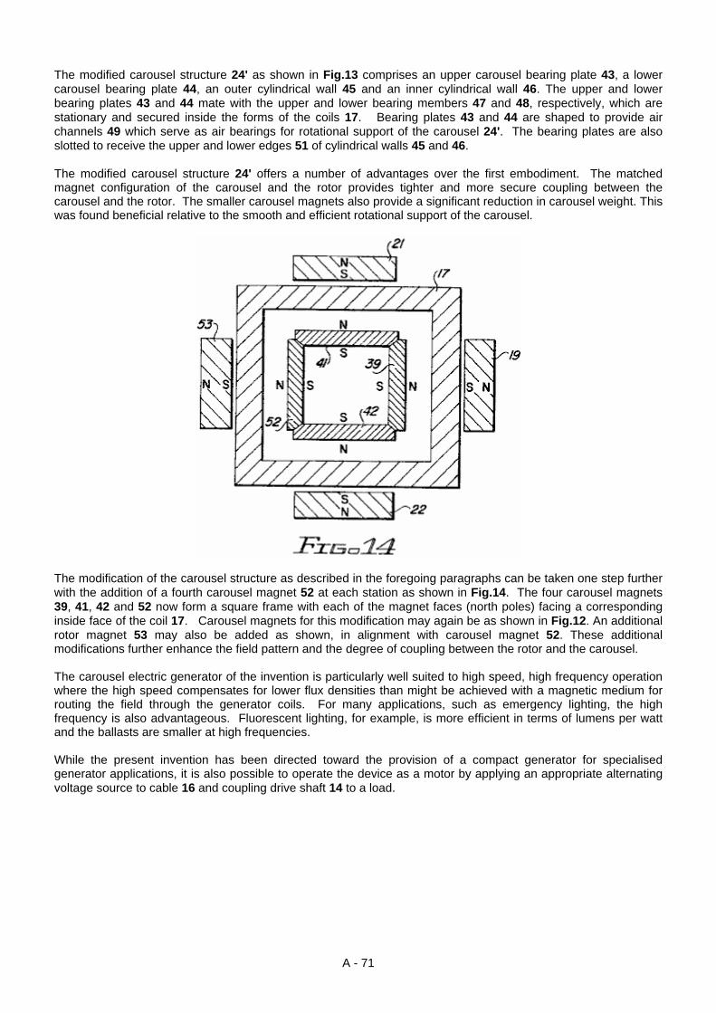
A - 71
The modified carousel structure 24' as shown in Fig.13 comprises an upper carousel bearing plate 43, a lower carousel bearing plate 44, an outer cylindrical wall 45 and an inner cylindrical wall 46. The upper and lower bearing plates 43 and 44 mate with the upper and lower bearing members 47 and 48, respectively, which are stationary and secured inside the forms of the coils 17. Bearing plates 43 and 44 are shaped to provide air channels 49 which serve as air bearings for rotational support of the carousel 24'. The bearing plates are also slotted to receive the upper and lower edges 51 of cylindrical walls 45 and 46. The modified carousel structure 24' offers a number of advantages over the first embodiment. The matched magnet configuration of the carousel and the rotor provides tighter and more secure coupling between the carousel and the rotor. The smaller carousel magnets also provide a significant reduction in carousel weight. This was found beneficial relative to the smooth and efficient rotational support of the carousel.
The modification of the carousel structure as described in the foregoing paragraphs can be taken one step further with the addition of a fourth carousel magnet 52 at each station as shown in Fig.14. The four carousel magnets 39, 41, 42 and 52 now form a square frame with each of the magnet faces (north poles) facing a corresponding inside face of the coil 17. Carousel magnets for this modification may again be as shown in Fig.12. An additional rotor magnet 53 may also be added as shown, in alignment with carousel magnet 52. These additional modifications further enhance the field pattern and the degree of coupling between the rotor and the carousel. The carousel electric generator of the invention is particularly well suited to high speed, high frequency operation where the high speed compensates for lower flux densities than might be achieved with a magnetic medium for routing the field through the generator coils. For many applications, such as emergency lighting, the high frequency is also advantageous. Fluorescent lighting, for example, is more efficient in terms of lumens per watt and the ballasts are smaller at high frequencies. While the present invention has been directed toward the provision of a compact generator for specialised generator applications, it is also possible to operate the device as a motor by applying an appropriate alternating voltage source to cable 16 and coupling drive shaft 14 to a load.
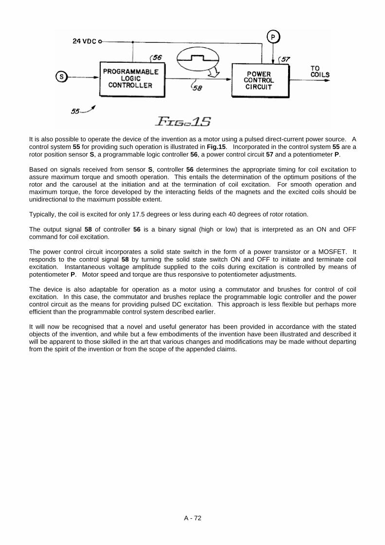
A - 72
It is also possible to operate the device of the invention as a motor using a pulsed direct-current power source. A control system 55 for providing such operation is illustrated in Fig.15. Incorporated in the control system 55 are a rotor position sensor S, a programmable logic controller 56, a power control circuit 57 and a potentiometer P. Based on signals received from sensor S, controller 56 determines the appropriate timing for coil excitation to assure maximum torque and smooth operation. This entails the determination of the optimum positions of the rotor and the carousel at the initiation and at the termination of coil excitation. For smooth operation and maximum torque, the force developed by the interacting fields of the magnets and the excited coils should be unidirectional to the maximum possible extent. Typically, the coil is excited for only 17.5 degrees or less during each 40 degrees of rotor rotation. The output signal 58 of controller 56 is a binary signal (high or low) that is interpreted as an ON and OFF command for coil excitation. The power control circuit incorporates a solid state switch in the form of a power transistor or a MOSFET. It responds to the control signal 58 by turning the solid state switch ON and OFF to initiate and terminate coil excitation. Instantaneous voltage amplitude supplied to the coils during excitation is controlled by means of potentiometer P. Motor speed and torque are thus responsive to potentiometer adjustments. The device is also adaptable for operation as a motor using a commutator and brushes for control of coil excitation. In this case, the commutator and brushes replace the programmable logic controller and the power control circuit as the means for providing pulsed DC excitation. This approach is less flexible but perhaps more efficient than the programmable control system described earlier. It will now be recognised that a novel and useful generator has been provided in accordance with the stated objects of the invention, and while but a few embodiments of the invention have been illustrated and described it will be apparent to those skilled in the art that various changes and modifications may be made without departing from the spirit of the invention or from the scope of the appended claims.
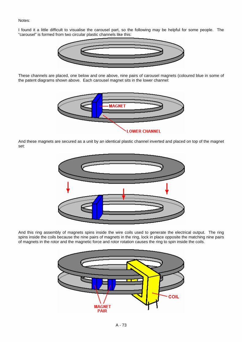
A - 73
Notes: I found it a little difficult to visualise the carousel part, so the following may be helpful for some people. The “carousel” is formed from two circular plastic channels like this:
These channels are placed, one below and one above, nine pairs of carousel magnets (coloured blue in some of the patent diagrams shown above. Each carousel magnet sits in the lower channel:
And these magnets are secured as a unit by an identical plastic channel inverted and placed on top of the magnet set:
And this ring assembly of magnets spins inside the wire coils used to generate the electrical output. The ring spins inside the coils because the nine pairs of magnets in the ring, lock in place opposite the matching nine pairs of magnets in the rotor and the magnetic force and rotor rotation causes the ring to spin inside the coils.
A - 74
PAVEL IMRIS: OPTICAL GENERATOR US Patent 3,781,601 25th December 1973 Inventor: Pavel Imris OPTICAL GENERATOR OF AN ELECTROSTATIC FIELD HAVING LONGITUDINAL OSCILLATION AT LIGHT
FREQUENCIES FOR USE IN AN ELECTRICAL CIRCUIT Please note that this is a re-worded excerpt from this patent. It describes a gas-filled tube which allows many standard 40-watt fluorescent tubes to be powered using less than 1-watt of power each. ABSTRACT An Optical generator of an electrostatic field at light frequencies for use in an electrical circuit, the generator having a pair of spaced-apart electrodes in a gas-filled tube of quartz glass or similar material with at least one capacitor cap or plate adjacent to one electrode and a dielectric filled container enclosing the tube, the generator substantially increasing the electrical efficiency of the electrical circuit. BACKGROUND OF THE INVENTION This invention relates to improved electrical circuits, and more particularly to circuits utilising an optical generator of an electrostatic field at light frequencies. The measure of the efficiency of an electrical circuit may broadly be defined as the ratio of the output energy in the desired form (such as light in a lighting circuit) to the input electrical energy. Up to now, the efficiency of many circuits has not been very high. For example, in a lighting circuit using 40 watt fluorescent lamps, only about 8.8 watts of the input energy per lamp is actually converted to visible light, thus representing an efficiency of only about 22%. The remaining 31.2 watts is dissipated primarily in the form of heat. It has been suggested that with lighting circuits having fluorescent lamps, increasing the frequency of the applied current will raise the overall circuit efficiency. While at an operating frequency of 60 Hz, the efficiency is 22%, if the frequency is raised to 1 Mhz, the circuit efficiency would only rise to some 25.5%. Also, if the input frequency were raised to 10 Ghz, the overall circuit efficiency would only be 35%. SUMMARY OF THE PRESENT INVENTION The present invention utilises an optical electrostatic generator which is effective for producing high frequencies in the visible light range of about 1014 to 1023 Hz. The operation and theory of the optical electrostatic generator has been described and discussed in my co-pending application serial No. 5,248, filed on 23rd January 1970. As stated in my co-pending application, the present optical electrostatic generator does not perform in accordance with the accepted norms and standards of ordinary electromagnetic frequencies. The optical electrostatic generator as utilised in the present invention can generate a wide range of frequencies between several Hertz and those in the light frequency. Accordingly, it is an object of the present invention to provide improved electrical energy circuits utilising my optical electrostatic generator, whereby the output energy in the desired form will be substantially more efficient than possible to date, using standard circuit techniques and equipment. It is a further object of the present invention to provide such a circuit for use in fluorescent lighting or other lighting circuits. It is also an object of the present invention to provide a circuit with may be used in conjunction with electrostatic precipitators for dust and particle collection and removal, as well as many other purposes. DESCRIPTION OF THE DRAWINGS Fig.1 is a schematic layout showing an optical electrostatic generator of the present invention, utilised in a lighting circuit for fluorescent lamps:
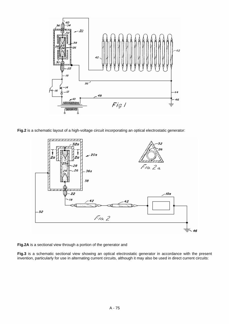
A - 75
Fig.2 is a schematic layout of a high-voltage circuit incorporating an optical electrostatic generator:
Fig.2A is a sectional view through a portion of the generator and Fig.3 is a schematic sectional view showing an optical electrostatic generator in accordance with the present invention, particularly for use in alternating current circuits, although it may also be used in direct current circuits:
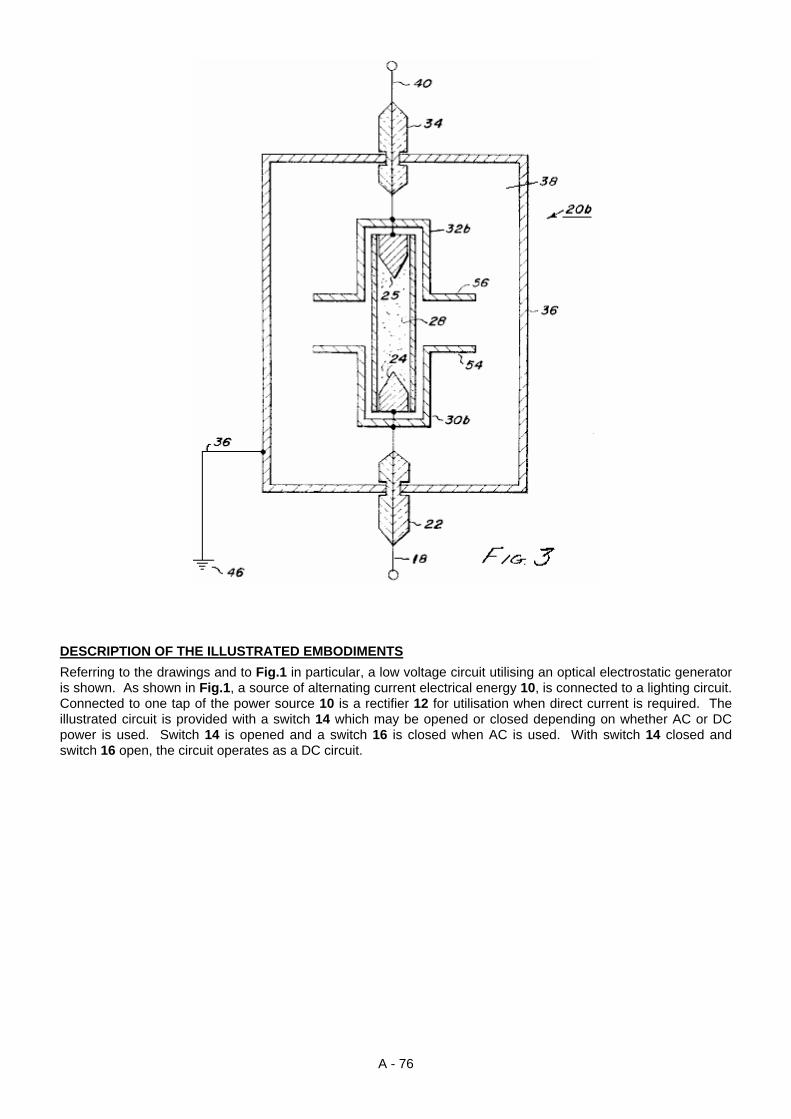
A - 76
DESCRIPTION OF THE ILLUSTRATED EMBODIMENTS Referring to the drawings and to Fig.1 in particular, a low voltage circuit utilising an optical electrostatic generator is shown. As shown in Fig.1, a source of alternating current electrical energy 10, is connected to a lighting circuit. Connected to one tap of the power source 10 is a rectifier 12 for utilisation when direct current is required. The illustrated circuit is provided with a switch 14 which may be opened or closed depending on whether AC or DC power is used. Switch 14 is opened and a switch 16 is closed when AC is used. With switch 14 closed and switch 16 open, the circuit operates as a DC circuit.

A - 77
Extending from switches 14 and 16 is conductor 18 which is connected to an optical electrostatic generator 20. Conductor 18 is passed through an insulator 22 and connected to an electrode 24. Spaced from electrode 24 is a second electrode 25. Enclosing electrodes 24 and 25, which preferably are made of tungsten or similar material, is a quartz glass tube 26 which is filled with an ionisable gas 28 such as xenon or any other suitable ionisable gas such as argon, krypton, neon, nitrogen or hydrogen, as well as the vapour of metals such as mercury or sodium. Surrounding each end of tube 26 and adjacent to electrodes 24 and 25, are capacitor plates 30 and 32 in the form of caps. A conductor is connected to electrode 25 and passed through a second insulator 34. Surrounding the tube, electrodes and capacitor caps is a metal envelope in the form of a thin sheet of copper or other metal such as aluminium. Envelope 36 is spaced from the conductors leading into and out of the generator by means of insulators 22 and 34. Envelope 36 is filled with a dielectric material such as transformer oil, highly purified distilled water, nitro-benzene or any other suitable liquid dielectric. In addition, the dielectric may be a solid such as ceramic material with relatively small molecules. A conductor 40 is connected to electrode 25, passed through insulator 24 and then connected to a series of fluorescent lamps 42 which are connected in series. It is the lamps 42 which will be the measure of the efficiency of the circuit containing the optical electrostatic generator 20. A conductor 44 completes the circuit from the fluorescent lamps to the tap of the source of electrical energy 10. In addition, the circuit is connected to a ground 46 by another conductor 48. Envelope 36 is also grounded by lead 50 and in the illustrated diagram, lead 50 is connected to the conductor 44. The capacitor caps or plates 30 and 32, form a relative capacitor with the discharge tube. When a high voltage is applied to the electrode of the discharge tube, the ions of gas are excited and brought to a higher potential than their environment, i.e. the envelope and the dielectric surrounding it. At this point, the ionised gas in effect becomes one plate of a relative capacitor in co-operation with the capacitor caps or plates 30 and 32. When this relative capacitor is discharged, the electric current does not decrease as would normally be expected. Instead, it remains substantially constant due to the relationship between the relative capacitor and an absolute capacitor which is formed between the ionised gas and the spaced metal envelope 36. An oscillation effect occurs in the relative capacitor, but the electrical condition in the absolute capacitor remains substantially constant. As also described in the co-pending application serial No. 5,248, there is an oscillation effect between the ionised gas in the discharge lamp and the metallic envelope 36 will be present if the capacitor caps are eliminated, but the efficiency of the electrostatic generator will be substantially decreased. The face of the electrode can be any desired shape. However, a conical point of 600 has been found to be satisfactory and it is believed to have an influence on the efficiency of the generator. In addition, the type of gas selected for use in tube 26, as well as the pressure of the gas in the tube, also affect the efficiency of the generator, and in turn, the efficiency of the electrical circuit.

A - 78
To demonstrate the increased efficiency of an electrical circuit utilising the optical electrostatic generator of the present invention as well as the relationship between gas pressure and electrical efficiency, a circuit similar to that shown in Fig.1 may be used with 100 standard 40 watt, cool-white fluorescent lamps connected in series. The optical electrostatic generator includes a quartz glass tube filled with xenon, with a series of different tubes being used because of the different gas pressures being tested.
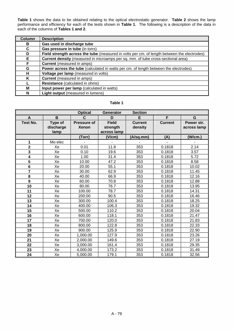
A - 79
Table 1 shows the data to be obtained relating to the optical electrostatic generator. Table 2 shows the lamp performance and efficiency for each of the tests shown in Table 1. The following is a description of the data in each of the columns of Tables 1 and 2.
Column Description B Gas used in discharge tube C Gas pressure in tube (in torrs) D Field strength across the tube (measured in volts per cm. of length between the electrodes) E Current density (measured in microamps per sq. mm. of tube cross-sectional area) F Current (measured in amps) G Power across the tube (calculated in watts per cm. of length between the electrodes) H Voltage per lamp (measured in volts) K Current (measured in amps) L Resistance (calculated in ohms) M Input power per lamp (calculated in watts) N Light output (measured in lumens)
Table 1
Optical Generator Section
A B C D E F G Test No. Type of
discharge lamp
Pressure of Xenon
Field strength
across lamp
Current density
Current Power str. across lamp
(Torr) (V/cm) (A/sq.mm) (A) (W/cm.) 1 Mo elec - - - - - 2 Xe 0.01 11.8 353 0.1818 2.14 3 Xe 0.10 19.6 353 0.1818 3.57 4 Xe 1.00 31.4 353 0.1818 5.72 5 Xe 10.00 47.2 353 0.1818 8.58 6 Xe 20.00 55.1 353 0.1818 10.02 7 Xe 30.00 62.9 353 0.1818 11.45 8 Xe 40.00 66.9 353 0.1818 12.16 9 Xe 60.00 70.8 353 0.1818 12.88
10 Xe 80.00 76.7 353 0.1818 13.95 11 Xe 100.00 78.7 353 0.1818 14.31 12 Xe 200.00 90.5 353 0.1818 16.46 13 Xe 300.00 100.4 353 0.1818 18.25 14 Xe 400.00 106.3 353 0.1818 19.32 15 Xe 500.00 110.2 353 0.1818 20.04 16 Xe 600.00 118.1 353 0.1818 21.47 17 Xe 700.00 120.0 353 0.1818 21.83 18 Xe 800.00 122.8 353 0.1818 22.33 19 Xe 900.00 125.9 353 0.1818 22.90 20 Xe 1,000.00 127.9 353 0.1818 23.26 21 Xe 2,000.00 149.6 353 0.1818 27.19 22 Xe 3,000.00 161.4 353 0.1818 29.35 23 Xe 4,000.00 173.2 353 0.1818 31.49 24 Xe 5,000.00 179.1 353 0.1818 32.56
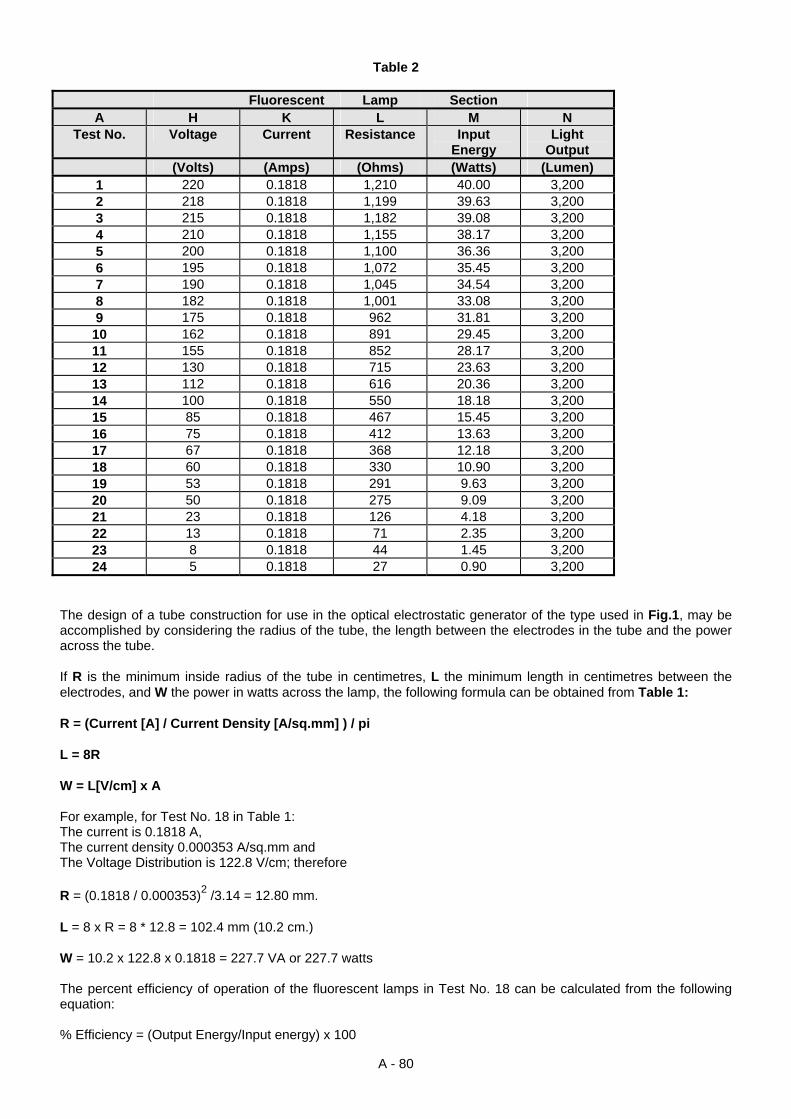
A - 80
Table 2
Fluorescent Lamp Section A H K L M N
Test No. Voltage Current Resistance Input Energy
Light Output
(Volts) (Amps) (Ohms) (Watts) (Lumen) 1 220 0.1818 1,210 40.00 3,200 2 218 0.1818 1,199 39.63 3,200 3 215 0.1818 1,182 39.08 3,200 4 210 0.1818 1,155 38.17 3,200 5 200 0.1818 1,100 36.36 3,200 6 195 0.1818 1,072 35.45 3,200 7 190 0.1818 1,045 34.54 3,200 8 182 0.1818 1,001 33.08 3,200 9 175 0.1818 962 31.81 3,200
10 162 0.1818 891 29.45 3,200 11 155 0.1818 852 28.17 3,200 12 130 0.1818 715 23.63 3,200 13 112 0.1818 616 20.36 3,200 14 100 0.1818 550 18.18 3,200 15 85 0.1818 467 15.45 3,200 16 75 0.1818 412 13.63 3,200 17 67 0.1818 368 12.18 3,200 18 60 0.1818 330 10.90 3,200 19 53 0.1818 291 9.63 3,200 20 50 0.1818 275 9.09 3,200 21 23 0.1818 126 4.18 3,200 22 13 0.1818 71 2.35 3,200 23 8 0.1818 44 1.45 3,200 24 5 0.1818 27 0.90 3,200
The design of a tube construction for use in the optical electrostatic generator of the type used in Fig.1, may be accomplished by considering the radius of the tube, the length between the electrodes in the tube and the power across the tube. If R is the minimum inside radius of the tube in centimetres, L the minimum length in centimetres between the electrodes, and W the power in watts across the lamp, the following formula can be obtained from Table 1: R = (Current [A] / Current Density [A/sq.mm] ) / pi L = 8R W = L[V/cm] x A For example, for Test No. 18 in Table 1: The current is 0.1818 A, The current density 0.000353 A/sq.mm and The Voltage Distribution is 122.8 V/cm; therefore R = (0.1818 / 0.000353)2 /3.14 = 12.80 mm. L = 8 x R = 8 * 12.8 = 102.4 mm (10.2 cm.) W = 10.2 x 122.8 x 0.1818 = 227.7 VA or 227.7 watts The percent efficiency of operation of the fluorescent lamps in Test No. 18 can be calculated from the following equation: % Efficiency = (Output Energy/Input energy) x 100
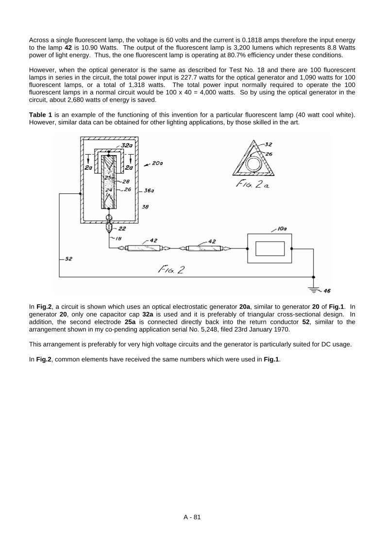
A - 81
Across a single fluorescent lamp, the voltage is 60 volts and the current is 0.1818 amps therefore the input energy to the lamp 42 is 10.90 Watts. The output of the fluorescent lamp is 3,200 lumens which represents 8.8 Watts power of light energy. Thus, the one fluorescent lamp is operating at 80.7% efficiency under these conditions. However, when the optical generator is the same as described for Test No. 18 and there are 100 fluorescent lamps in series in the circuit, the total power input is 227.7 watts for the optical generator and 1,090 watts for 100 fluorescent lamps, or a total of 1,318 watts. The total power input normally required to operate the 100 fluorescent lamps in a normal circuit would be 100 x 40 = 4,000 watts. So by using the optical generator in the circuit, about 2,680 watts of energy is saved. Table 1 is an example of the functioning of this invention for a particular fluorescent lamp (40 watt cool white). However, similar data can be obtained for other lighting applications, by those skilled in the art.
In Fig.2, a circuit is shown which uses an optical electrostatic generator 20a, similar to generator 20 of Fig.1. In generator 20, only one capacitor cap 32a is used and it is preferably of triangular cross-sectional design. In addition, the second electrode 25a is connected directly back into the return conductor 52, similar to the arrangement shown in my co-pending application serial No. 5,248, filed 23rd January 1970. This arrangement is preferably for very high voltage circuits and the generator is particularly suited for DC usage. In Fig.2, common elements have received the same numbers which were used in Fig.1.
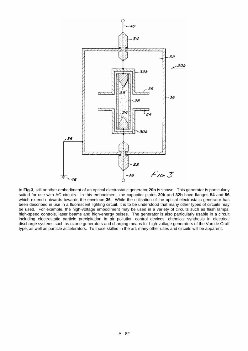
A - 82
In Fig.3, still another embodiment of an optical electrostatic generator 20b is shown. This generator is particularly suited for use with AC circuits. In this embodiment, the capacitor plates 30b and 32b have flanges 54 and 56 which extend outwards towards the envelope 36. While the utilisation of the optical electrostatic generator has been described in use in a fluorescent lighting circuit, it is to be understood that many other types of circuits may be used. For example, the high-voltage embodiment may be used in a variety of circuits such as flash lamps, high-speed controls, laser beams and high-energy pulses. The generator is also particularly usable in a circuit including electrostatic particle precipitation in air pollution control devices, chemical synthesis in electrical discharge systems such as ozone generators and charging means for high-voltage generators of the Van de Graff type, as well as particle accelerators. To those skilled in the art, many other uses and circuits will be apparent.

A - 83
HAROLD COLMAN & RONALD SEDDON-GILLESPIE: 70-YEAR BATTERY
Patent GB 763,062 5th December 1956 Inventors: Harold Colman and Ronald Seddon-Gillespie
APPARATUS FOR PRODUCING AN ELECTRIC CURRENT This patent shows the details of a lightweight device which can produce electricity using a self-powered electromagnet and chemical salts. The working life of the device before needing a recharge is estimated at some seventy years. The operation is controlled by a transmitter which bombards the chemical sample with 300 MHz radio waves. This produces radioactive emissions from the chemical mixture for a period of one hour maximum, so the transmitter needs to be run for fifteen to thirty seconds once every hour. The chemical mixture is shielded by a lead screen to prevent harmful radiation reaching the user. The output from the tiny device described is estimated to be some 10 amps at 100 to 110 volts DC. DESCRIPTION This invention relates to a new apparatus for producing electric current the apparatus being in the form of a completely novel secondary battery. The object of this invention is to provide apparatus of the above kind which is considerably lighter in weight than, and has an infinitely greater life than a known battery or similar characteristics and which can be re-activated as and when required in a minimum of time. According to the present invention we provide apparatus comprising a generator unit which includes a magnet, a means for suspending a chemical mixture in the magnetic field, the mixture being composed of elements whose nuclei becomes unstable as a result of bombardment by short waves so that the elements become radio-active and release electrical energy, the mixture being mounted between, and in contact with, a pair of different metals such as copper and zinc, a capacitor mounted between those metals, a terminal electrically connected to each of the metals, means for conveying the waves to the mixture and a lead shield surrounding the mixture to prevent harmful radiation from the mixture. The mixture is preferably composed of the elements Cadmium, Phosphorus and Cobalt having Atomic Weights of 112, 31 and 59 respectively. The mixture, which may be of powdered form, is mounted in a tube of non-conducting, high heat resistivity material and is compressed between granulated zinc at one end of the tube and granulated copper at the other end, the ends of the tube being closed by brass caps and the tube being carried in a suitable cradle so that it is located between the poles of the magnet. The magnet is preferably an electro-magnet and is energised by the current produced by the unit. The means for conveying the waves to the mixture may be a pair of antennae which are exactly similar to the antennae of the transmitter unit for producing the waves, each antenna projecting from and being secured to the brass cap at each end of the tube. The transmitter unit which is used for activating the generator unit may be of any conventional type operating on ultra-shortwave and is preferably crystal controlled at the desired frequency. DESCRIPTION OF THE DRAWINGS

A - 84
Fig.1 is a side elevation of one form of the apparatus.
Fig.2 is a view is an end elevation
Fig.3 is a schematic circuit diagram. In the form of our invention illustrated, the generator unit comprises a base 10 upon which the various components are mounted. This base 10, having projecting upwards from it a pair of arms 11, which form a cradle housing 12 for a quartz tube 13, the cradle 12 preferably being made of spring material so that the tube 13 is firmly, yet removably held in position. The arms 11 are positioned relative to the poles 14 of an electromagnet 15 so that the tube 13 is located immediately between the poles of the magnet so as to be in the strongest magnetic field created by the electromagnet. The magnet serves to control the alpha and beta rays emitted by the cartridge when it is in operation.
A - 85
The ends of the quartz tube 13 are each provided with a brass cap 16, and these caps 16 are adapted to engage within the spring cradles 12 and the coils 17 associated with the magnet being so arranged that if the base 10 of the unit is in a horizontal plane, the poles 14 of the magnet are in a substantially vertical plane. Also connected across the cradles is a lead capacitor 18 which may conveniently be housed in the base 10 of the unit and connected in parallel with this capacitor 18 is a suitable high frequency inductance coil 19. The unit is provided with a lead shield 20 so as to prevent harmful radiation from the quartz tube as will be described later. The quartz tube 13 has mounted in it, at one end, a quantity of granulated copper which is in electrical contact with the brass cap 16 at that end of the tube. Also mounted within the tube and in contact with the granulated copper is a chemical mixture which is in powdered form and which is capable of releasing electrical energy and which becomes radioactive when subjected to bombardment by ultra-short radio waves. Mounted in the other end of the tube, and in contact with the other end of the powdered chemical mixture is a quantity of granulated zinc which is itself in contact with the brass cap on this end of the tube, the arrangement being that the chemical mixture is compressed between the granulated copper and the granulated zinc. Projecting outwards from each brass cap 16, and electrically connected to them, is an antenna 21. Each antenna 21 corresponding exactly in dimension, shape and electrical characteristics to the antenna associated with a transmitter unit which is to produce the ultra shortwaves mentioned earlier. The electromagnet 15 is conveniently carried by a centrally positioned pillar 22 which is secured to the base 10. At the upper end of pillar 22 there is a cross-bar 23, which has the high frequency coil 19 attached to one end of it. The other end of the cross-bar 23 is bent around into the curved shape as shown at 24 and is adapted to bear against a curved portion 25 of the base 26 of the electromagnet 15. A suitable locking device is provided for holding the curved portions 24 and 25 in the desired angular position, so that the position of the poles 14 of the electromagnet can be adjusted about the axis of the quartz tube 13. The transmitter unit is of any suitable conventional type for producing ultra shortwaves and may be crystal controlled to ensure that it operates at the desired frequency with the necessity of tuning. If the transmitter is only required to operate over a short range, it may conveniently be battery powered but if it is to operate over a greater range, then it may be operated from a suitable electrical supply such as the mains. If the transmitter is to be tuned, then the tuning may be operated by a dial provided with a micrometer vernier scale so that the necessary tuning accuracy may be achieved. The mixture which is contained within the quartz tube is composed of the elements Cadmium, Phosphorus and Cobalt, having atomic weights 112, 31 and 59 respectively. Conveniently, these elements may be present in the following compounds, and where the tube is to contain thirty milligrams of the mixture, the compounds and their proportions by weight are: 1 Part of Co (No3) 2 6H2O 2 Parts of CdCl2 3 Parts of 3Ca (Po3) 2 + 10C. The cartridge which consists of the tube 13 with the chemical mixture in it is preferably composed of a number of small cells built up in series. In other words, considering the cartridge from one end to the other, at one end and in contact with the brass cap, there would be a layer of powdered copper, then a layer of the chemical mixture, then a layer of powdered zinc, a layer of powdered copper, etc. with a layer of powdered zinc in contact with the brass cap at the other end of the cartridge. With a cartridge some forty five millimetres long and five millimetres diameter, some fourteen cells may be included. The cradles 12 in which the brass caps 16 engage, may themselves form terminals from which the output of the unit may be taken. Alternatively, a pair of terminals 27 may be connected across the cradles 12, these terminals 27 being themselves provided with suitable antennae 28, which correspond exactly in dimensions, shape and electrical characteristics to the antennae associated with the transmitter, these antennae 28, replacing the antennae 21. In operation with the quartz tube containing the above mixture located between the granulated copper and the granulated zinc and with the tube itself in position between the poles of the magnet, the transmitter is switched on and the ultra shortwaves coming from it are received by the antennae mounted at each end of the tube and in contact with the copper and zinc respectively, the waves being thus passed through the copper and zinc and through the mixture so that the mixture is bombarded by the short waves and the Cadmium, Phosphorus and Cobalt associated with the mixture become radioactive and release electrical energy which is transmitted to the granulated copper and granulated zinc, causing a current to flow between them in a similar manner to the current
A - 86
flow produced by a thermo couple. It has been established that with a mixture having the above composition, the optimum release of energy is obtained when the transmitter is operating at a frequency of 300 MHz. The provision of a quartz tube is necessary for the mixture evolves a considerable amount of heat while it is reacting to the bombardment of the short waves. It is found that the tube will only last for one hour and that the tube will become discharged after an hours operation, that is to say, the radioactiveness of the tube will only last for one hour and it is therefore necessary, if the unit is to be run continuously, for the transmitter to be operated for a period of some fifteen to thirty seconds duration once every hour. With a quartz tube having an overall length of some forty five millimetres and an inside diameter of five millimetres and containing thirty milligrams of the chemical mixture, the estimated energy which will be given off from the tube for a discharge of one hour, is 10 amps at between 100 and 110 volts. To enable the tube to give off this discharge, it is only necessary to operate the transmitter at the desired frequency for a period of some fifteen to thirty seconds duration. The current which is given off by the tube during its discharge is in the form of direct current. During the discharge from the tube, harmful radiations are emitted in the form of gamma rays, alpha rays and beta rays and it is therefore necessary to mount the unit within a lead shield to prevent the harmful radiations from affecting personnel and objects in the vicinity of the unit. The alpha and beta rays which are emitted from the cartridge when it is in operation are controlled by the magnet. When the unit is connected up to some apparatus which is to be powered by it, it is necessary to provide suitable fuses to guard against the cartridge being short-circuited which could cause the cartridge to explode. The estimated weight of such a unit including the necessary shielding, per kilowatt hour output, is approximately 25% of any known standard type of accumulator which is in use today and it is estimated that the life of the chemical mixture is probably in the region of seventy to eighty years when under constant use. It will thus be seen that we have provided a novel form of apparatus for producing an electric current, which is considerably lighter than the standard type of accumulator at present known, and which has an infinitely greater life than the standard type of accumulator, and which can be recharged or reactivated as and when desired and from a remote position depending on the power output of the transmitter. Such form of battery has many applications.
A - 87
JONG-SOK AN: NO-LOAD GENERATOR
Patent US 6,208,061 27th March 2001 Inventor: Jong-Sok An
NO-LOAD GENERATOR Electrical power is frequently generated by spinning the shaft of a generator which has some arrangement of coils and magnets contained within it. The problem is that when current is drawn from the take-off coils of a typical generator, it becomes much more difficult to spin the generator shaft. The cunning design shown in this patent overcomes this problem with a simple design in which the effort required to turn the shaft is not altered by the current drawn from the generator. ABSTRACT A generator of the present invention is formed of ring permanent magnet trains 2 and 2' attached and fixed on to two orbits 1 and 1' about a rotational axis 3, magnetic induction primary cores 4 and 4' attached and fixed above outer peripheral surfaces of the ring permanent magnet trains 2 and 2' at a predetermined distance from the outer peripheral surfaces, magnetic induction secondary cores 5 and 5' attached and fixed on to the magnetic induction primary cores 4 and 4' and each having two coupling, holes 6 and 6' formed therein, tertiary cores 8 and 8' inserted for coupling respectively into two coupling holes 6 and 6' of each of the associated magnetic induction secondary cores 5 and 5' opposite to each other, and responsive coils 7 and 7'. The ring permanent magnetic trains 2 and 2' are formed of 8 sets of magnets with alternating N and S poles, and magnets associated with each other in the axial direction have opposite polarities respectively and form a pair. DESCRIPTION TECHNICAL FIELD The present invention relates to generators, and particularly to a load-free generator which can maximise the generator efficiency by erasing or eliminating the secondary repulsive load exerted on the rotor during electric power generation. BACKGROUND ART The generator is a machine which converts mechanical energy obtained from sources of various types of energy such as physical, chemical or nuclear power energy, for example, into electric energy. Generators based on linear motion have recently been developed while most generators are structured as rotational type generators. Generation of electromotive force by electromagnetic induction is a common principle to generators regardless of their size or whether the generator is AC or DC generator. The generator requires a strong magnet such as permanent magnet and electromagnet for generating magnetic field as well as a conductor for generating the electromotive force, and the generator is structured to enable one of them to rotate relative to the other. Depending on which of the magnet and the conductor rotates, generators can be classified into rotating-field type generators in which the magnetic field rotates and rotating-armature type generators in which the conductor rotates. Although the permanent magnet can be used for generating the magnetic field, the electromagnet is generally employed which is formed of a magnetic field coil wound around a core to allow direct current to flow through them. Even if a strong magnet is used to enhance the rotational speed, usually the electromotive force produced from one conductor is not so great. Thus, in a generally employed system, a large number of conductors are provided in the generator and the electromotive forces generated from respective conductare serially added up so as to achieve a high electric power. As discussed above, a usual generator produces electricity by mechanically rotating a magnet (or permanent magnet) or a conductor (electromagnet, electrically responsive coil and the like) while reverse current generated at this time by magnetic induction (electromagnetic induction) and flowing through the coil causes magnetic force which pulls the rotor so that the rotor itself is subjected to unnecessary load which reaches at least twice the electric power production.
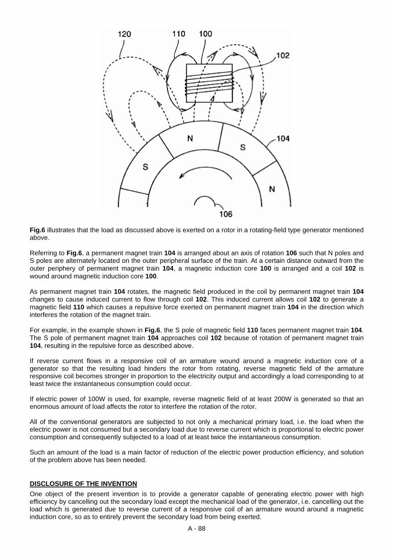
A - 88
Fig.6 illustrates that the load as discussed above is exerted on a rotor in a rotating-field type generator mentioned above. Referring to Fig.6, a permanent magnet train 104 is arranged about an axis of rotation 106 such that N poles and S poles are alternately located on the outer peripheral surface of the train. At a certain distance outward from the outer periphery of permanent magnet train 104, a magnetic induction core 100 is arranged and a coil 102 is wound around magnetic induction core 100. As permanent magnet train 104 rotates, the magnetic field produced in the coil by permanent magnet train 104 changes to cause induced current to flow through coil 102. This induced current allows coil 102 to generate a magnetic field 110 which causes a repulsive force exerted on permanent magnet train 104 in the direction which interferes the rotation of the magnet train. For example, in the example shown in Fig.6, the S pole of magnetic field 110 faces permanent magnet train 104. The S pole of permanent magnet train 104 approaches coil 102 because of rotation of permanent magnet train 104, resulting in the repulsive force as described above. If reverse current flows in a responsive coil of an armature wound around a magnetic induction core of a generator so that the resulting load hinders the rotor from rotating, reverse magnetic field of the armature responsive coil becomes stronger in proportion to the electricity output and accordingly a load corresponding to at least twice the instantaneous consumption could occur. If electric power of 100W is used, for example, reverse magnetic field of at least 200W is generated so that an enormous amount of load affects the rotor to interfere the rotation of the rotor. All of the conventional generators are subjected to not only a mechanical primary load, i.e. the load when the electric power is not consumed but a secondary load due to reverse current which is proportional to electric power consumption and consequently subjected to a load of at least twice the instantaneous consumption. Such an amount of the load is a main factor of reduction of the electric power production efficiency, and solution of the problem above has been needed. DISCLOSURE OF THE INVENTION One object of the present invention is to provide a generator capable of generating electric power with high efficiency by cancelling out the secondary load except the mechanical load of the generator, i.e. cancelling out the load which is generated due to reverse current of a responsive coil of an armature wound around a magnetic induction core, so as to entirely prevent the secondary load from being exerted.

A - 89
In short, the present invention is applied to a load-free generator including a rotational axis, a first ring magnet train, a second ring magnet train, a first plurality of first magnetic induction primary cores, a first plurality of second magnetic induction primary cores, a first responsive coil, and a second responsive coil. The first ring magnet train has N poles and S poles successively arranged on an outer periphery of a first rotational orbit about the rotational axis. The second ring magnet train has magnets successively arranged on an outer periphery of a second rotational orbit about the rotational axis at a predetermined distance from the first rotational orbit such that the polarities of the magnets on the second rotational orbit are opposite to the polarities at opposite locations on the first rotational orbit respectively. The first plurality of first magnetic induction primary cores are fixed along a first peripheral surface of the first ring magnet train at a predetermined distance from the first peripheral surface. The first plurality of second magnetic induction primary cores are fixed along a second peripheral surface of the second ring magnet train at a predetermined distance from the second peripheral surface. A first plurality of first coupling magnetic induction cores and a first plurality of second coupling magnetic induction cores are provided in pairs to form a closed magnetic circuit between the first and second magnetic induction primary cores opposite to each other in the direction of the rotational axis. The first responsive coil is wound around the first coupling magnetic induction core. The second responsive coil is wound around the second coupling magnetic induction core, the direction of winding of the second responsive coil being reversed relative to the first responsive coil. Preferably, in the load-free generator of the invention, the first ring magnet train includes a permanent magnet train arranged along the outer periphery of the first rotational orbit, and the second ring magnet train includes a permanent magnet train arranged along the outer periphery of the second rotational orbit. Still preferably, the load-free generator of the present invention further includes a first plurality of first magnetic induction secondary cores provided on respective outer peripheries of the first magnetic induction primary cores and each having first and second coupling holes, and a first plurality of second magnetic induction secondary cores provided on respective outer peripheries of the second magnetic induction primary cores and each having third and fourth coupling holes. The first coupling magnetic induction cores are inserted into the first and third coupling holes to couple the first and second magnetic induction secondary cores, and the second coupling magnetic induction cores are inserted into the second and fourth coupling holes to couple the first and second magnetic induction secondary cores. Alternatively, the load-free generator of the present invention preferably has a first plurality of first responsive coils arranged in the rotational direction about the rotational aids that are connected zigzag to each other and a first plurality of second responsive coils arranged in the rotational direction about the rotational axis that are connected zigzag to each other. Alternatively, in the load-free generator of the present invention, preferably the first plurality is equal to 8, and the 8 first responsive coils arranged in the rotational direction about the rotational axis are connected zigzag to each other, and the 8 second responsive coils arranged in the rotational direction about the rotational axis are connected zigzag to each other. Accordingly, a main advantage of the present invention is that two responsive coils wound respectively in opposite directions around a paired iron cores are connected to cancel reverse magnetic forces generated by reverse currents (induced currents) flowing through the two responsive coils, so that the secondary load which interferes the rotation of the rotor is totally prevented and thus a load-free generator can be provided which is subjected to just a load which is equal to or less than mechanical load when electric power production is not done, i.e. the rotational load even when the generator is operated to the maximum. Another advantage of the present invention is that the reverse magnetic force, as found in the conventional generators, due to reverse current occurring when the rotor rotates is not generated, and accordingly load of energy except the primary gravity of the rotor and dynamic energy of the rotor is eliminated to increase the amount of electricity output relative to the conventional electric power generation system and thus enhance the electric power production and economic efficiency. BRIEF DESCRIPTION OF THE DRAWINGS

A - 90
Fig.1 is a cross sectional view of a rotating-field type generator according to an embodiment of the present invention illustrating an arrangement a permanent magnet, magnetic induction cores and coils.
Fig.2 is a partial schematic view illustrating a magnetic array of the permanent magnet rotor and an arrangement of one of magnetically responsive coils placed around that rotor in an embodiment of the present invention.
Fig.3 illustrates a structure of the magnetically responsive coils and cores in the embodiment of the present invention.
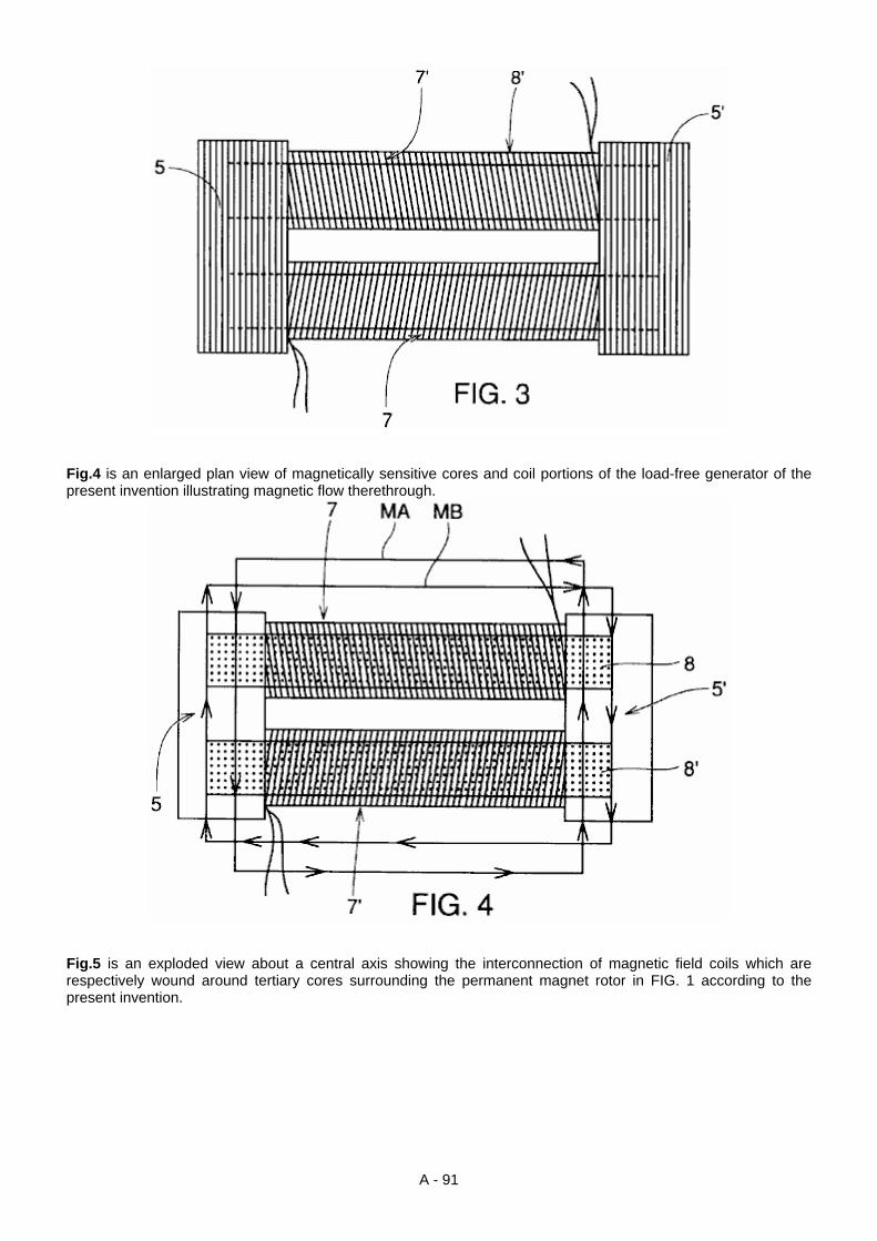
A - 91
Fig.4 is an enlarged plan view of magnetically sensitive cores and coil portions of the load-free generator of the present invention illustrating magnetic flow therethrough.
Fig.5 is an exploded view about a central axis showing the interconnection of magnetic field coils which are respectively wound around tertiary cores surrounding the permanent magnet rotor in FIG. 1 according to the present invention.

A - 92
Fig.6 illustrates generation of the secondary load in a conventional generator.
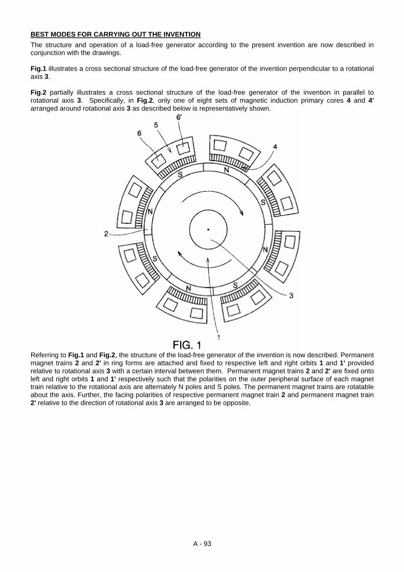
A - 93
BEST MODES FOR CARRYING OUT THE INVENTION The structure and operation of a load-free generator according to the present invention are now described in conjunction with the drawings. Fig.1 illustrates a cross sectional structure of the load-free generator of the invention perpendicular to a rotational axis 3. Fig.2 partially illustrates a cross sectional structure of the load-free generator of the invention in parallel to rotational axis 3. Specifically, in Fig.2, only one of eight sets of magnetic induction primary cores 4 and 4' arranged around rotational axis 3 as described below is representatively shown.
Referring to Fig.1 and Fig.2, the structure of the load-free generator of the invention is now described. Permanent magnet trains 2 and 2' in ring forms are attached and fixed to respective left and right orbits 1 and 1' provided relative to rotational axis 3 with a certain interval between them. Permanent magnet trains 2 and 2' are fixed onto left and right orbits 1 and 1' respectively such that the polarities on the outer peripheral surface of each magnet train relative to the rotational axis are alternately N poles and S poles. The permanent magnet trains are rotatable about the axis. Further, the facing polarities of respective permanent magnet train 2 and permanent magnet train 2' relative to the direction of rotational axis 3 are arranged to be opposite.
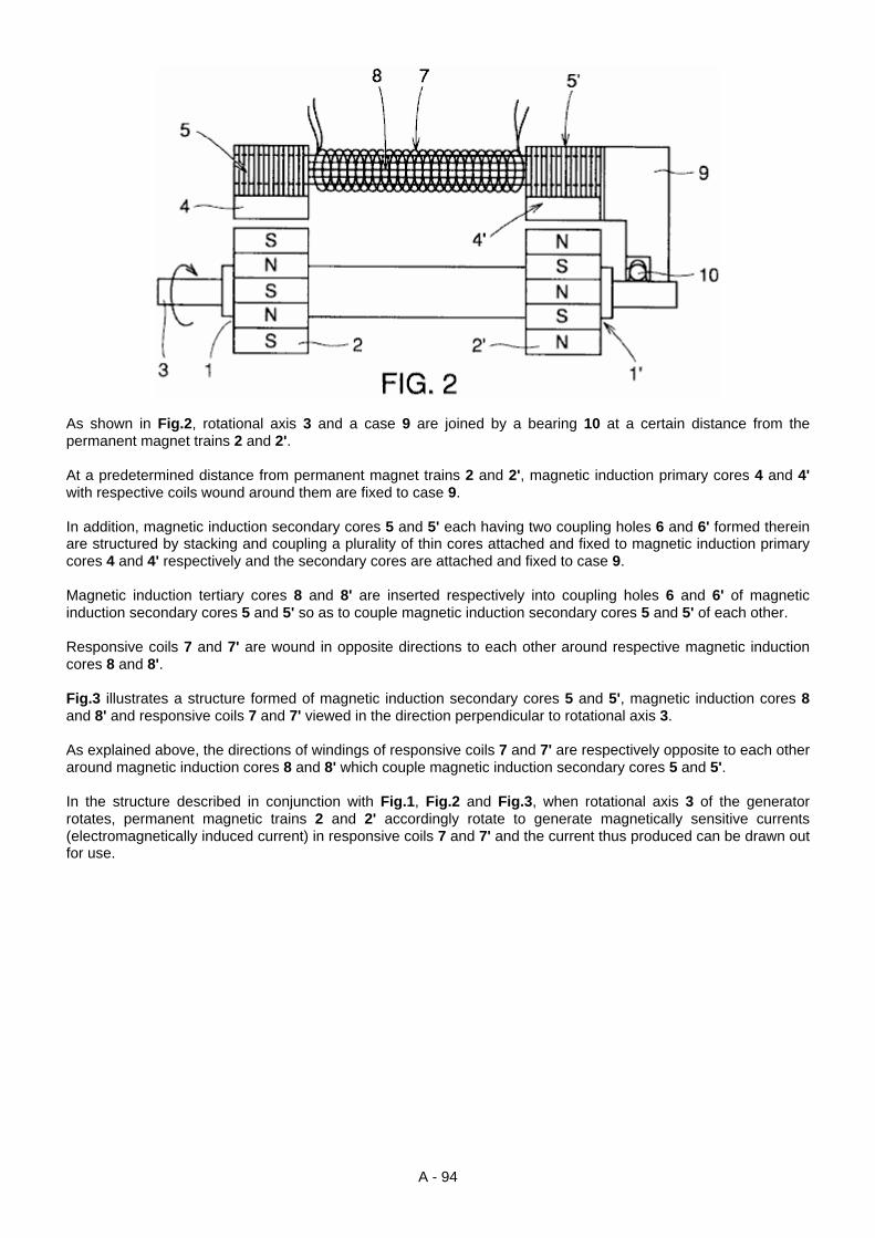
A - 94
As shown in Fig.2, rotational axis 3 and a case 9 are joined by a bearing 10 at a certain distance from the permanent magnet trains 2 and 2'. At a predetermined distance from permanent magnet trains 2 and 2', magnetic induction primary cores 4 and 4' with respective coils wound around them are fixed to case 9. In addition, magnetic induction secondary cores 5 and 5' each having two coupling holes 6 and 6' formed therein are structured by stacking and coupling a plurality of thin cores attached and fixed to magnetic induction primary cores 4 and 4' respectively and the secondary cores are attached and fixed to case 9. Magnetic induction tertiary cores 8 and 8' are inserted respectively into coupling holes 6 and 6' of magnetic induction secondary cores 5 and 5' so as to couple magnetic induction secondary cores 5 and 5' of each other. Responsive coils 7 and 7' are wound in opposite directions to each other around respective magnetic induction cores 8 and 8'. Fig.3 illustrates a structure formed of magnetic induction secondary cores 5 and 5', magnetic induction cores 8 and 8' and responsive coils 7 and 7' viewed in the direction perpendicular to rotational axis 3. As explained above, the directions of windings of responsive coils 7 and 7' are respectively opposite to each other around magnetic induction cores 8 and 8' which couple magnetic induction secondary cores 5 and 5'. In the structure described in conjunction with Fig.1, Fig.2 and Fig.3, when rotational axis 3 of the generator rotates, permanent magnetic trains 2 and 2' accordingly rotate to generate magnetically sensitive currents (electromagnetically induced current) in responsive coils 7 and 7' and the current thus produced can be drawn out for use.
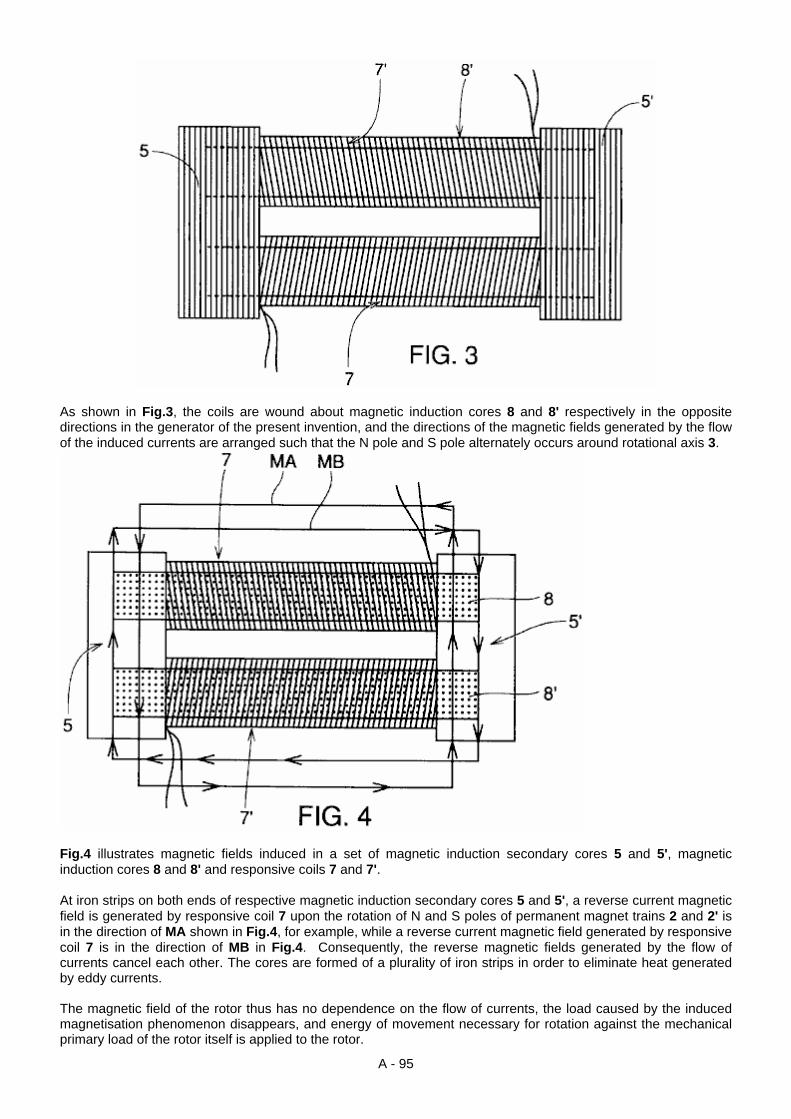
A - 95
As shown in Fig.3, the coils are wound about magnetic induction cores 8 and 8' respectively in the opposite directions in the generator of the present invention, and the directions of the magnetic fields generated by the flow of the induced currents are arranged such that the N pole and S pole alternately occurs around rotational axis 3.
Fig.4 illustrates magnetic fields induced in a set of magnetic induction secondary cores 5 and 5', magnetic induction cores 8 and 8' and responsive coils 7 and 7'. At iron strips on both ends of respective magnetic induction secondary cores 5 and 5', a reverse current magnetic field is generated by responsive coil 7 upon the rotation of N and S poles of permanent magnet trains 2 and 2' is in the direction of MA shown in Fig.4, for example, while a reverse current magnetic field generated by responsive coil 7 is in the direction of MB in Fig.4. Consequently, the reverse magnetic fields generated by the flow of currents cancel each other. The cores are formed of a plurality of iron strips in order to eliminate heat generated by eddy currents. The magnetic field of the rotor thus has no dependence on the flow of currents, the load caused by the induced magnetisation phenomenon disappears, and energy of movement necessary for rotation against the mechanical primary load of the rotor itself is applied to the rotor.

A - 96
At this time, a magnetic circuit including magnetic induction secondary cores 5 and 5' and magnetic induction tertiary cores 8 and 8' should be shaped into ".quadrature." form. If the circuit does not structured as ".quadrature." form, a part of the reverse magnetic field functions as electrical force which hinders the rotational force of the rotor. Further, permanent magnet trains 2 and 2' of the rotor are arranged to have opposite poles to each other on the left and right sides as shown in Fig.2 so as to constitute the flow of magnetic flux. Each rotor has alternately arranged magnets, for example, eight poles are provided to enhance the generator efficiency. More detailed description of the operational principle is given now. When the rotor in Fig.1 rotates once, S and N poles of permanent magnets 2 and 2' attached to the periphery of the rotor successively supply magnetic fields to induction primary cores 4 above, and magnetic field is accordingly generated in a path from one orbit of the rotor along induction primary core 4, induction secondary core 5, induction tertiary core 8, induction secondary core 5', induction primary core 4' to the other orbit of the rotor as shown in Fig.2. Accordingly, current flows in the coils affected by this electric field to generate electric power. For example, if the generated power is used as generated output for switching on an electric light or for using it as motive energy, the current flowing through the coils generates the reverse magnetic fields. However, this reverse magnetic fields do not influence permanent magnets 2 and 2' attached to the rotor in Fig.2 since the reverse magnetic fields of the same magnitude respectively of S and N or N and S on both ends of magnetic induction secondary cores 5 and 5' cancel out each other as shown in Fig.4. Because of this, the rotor is in a no-load state in which any resistance except the weight of the rotor itself and dynamic resistance is not exerted on the rotor.
Fig.5 illustrates a manner of connecting magnetically responsive coils 7 and 7' wound around magnetic induction tertiary cores 8 and 8' with eight poles. Referring to Fig.5, according to a method of connecting magnetically responsive coils 7 and 7' , line 1a1 of responsive coil 7' (one drawn-out line of the wire coiled around a first magnetic induction core 8) is connected to line 1a2' (one drawn-out line of the wire coiled around a second magnetic induction core 8), and then line 1a2 (the other drawn-out line of the wire coiled around a second magnetic induction core 8) is connected to line 1a3', and subsequently lines 1a and 1a' are connected successively in zigzag manner to allow current to flow. Further, responsive coil 7 is arranged to connect lines represented by 1b1 in zigzag manner such that lines 1b and 1b' are successively connected. In this way, lines 1b, 1b' and lines 1a and 1a' of respective magnetically responsive coils 7 and 7' are connected. As a whole, total four electric wires are drawn out for use.

A - 97
When electric power is to be generated according to the present invention as described above, specifically, a closed circuit is formed by responsive coils 7 and 7', electric currents are induced in responsive coils 7 and 7' wound around the magnetic induction cores of the generator, and the induced magnetic fields produced respectively by responsive coils 7 and 7' could cause a great load which interferes the rotational force of the rotor. However, as shown in Fig.4, the direction of convolution of one coil 7 is opposite to that of the other coil 7' so that the magnetic force generated by the reverse currents (induced currents) in responsive coils 7 and 7' wound around magnetic induction core 4 is not transmitted to magnetic induction cores 8 and 8 accordingly no reverse magnetic force is transmitted to permanent magnets 2 and 2'. Therefore, each time the N poles and S poles alternate with each other because of the alternation of permanent magnets 2 and 2' shown in Fig.2, the reverse magnetic forces in the right and left direction opposite to the direction of arrows denoted by MA and MB completely disappear as shown in Fig.4. Consequently, the reverse magnetic forces caused by the reverse currents are not influenced by permanent magnets 2 and 2' and accordingly no load except the mechanical primary load is exerted on the generator of the invention. As discussed above, the load-free generator of the present invention, secondary load except mechanical load of the generator, i.e. the load caused by the reverse currents flowing through the responsive coils can be nulled. With regard to this load-free generator, even if 100% of the current generated by magnetic induction (electromagnetic induction) is used, the magnetic secondary load due to the reverse currents except the mechanical primary load does not serve as load. Although the number of poles of the rotor is described as 8 in the above description, the present invention is not limited to such a structure, and the invention can exhibit its effect when the smaller or greater number of poles is applied. Further, although the magnet of the rotor is described as the permanent magnet in the above structure, the invention is not limited to such a case and the magnet of the rotor may be an electromagnet, for example. In addition, although the description above is applied to the structure of the rotating-field type generator, the generator may be of the rotating-armature type. EXPERIMENTAL EXAMPLE More detailed description of the generator of the present invention is hereinafter given based on specific experimental examples of the invention. The generator of the present invention and a conventional generator were used to measure the electric power production efficiency and the amount of load and compare the resultant measurements. EXPERIMENTAL EXAMPLE 1 A 12-pole alternating current (AC) generator for battery charging was used, and the electricity output and the load when 50% of the electricity output was used as well as those when 100% of the electricity output was used were measured. The generator above is a single-phase AC motor and the employed power source was 220V, with 1750 rpm and the efficiency of 60%. The result of measurement using power of a motor of 0.5HP and ampere .times.volt gauge is shown in Table 1. EXPERIMENTAL EXAMPLE 2 Measurement was done under the same conditions as those of experimental example 1 and a generator used was the one which was made according to the present invention to have the same conditions as those of the product of the existing model above. The result of measurement using ampere x volt gauge is shown in Table 1.
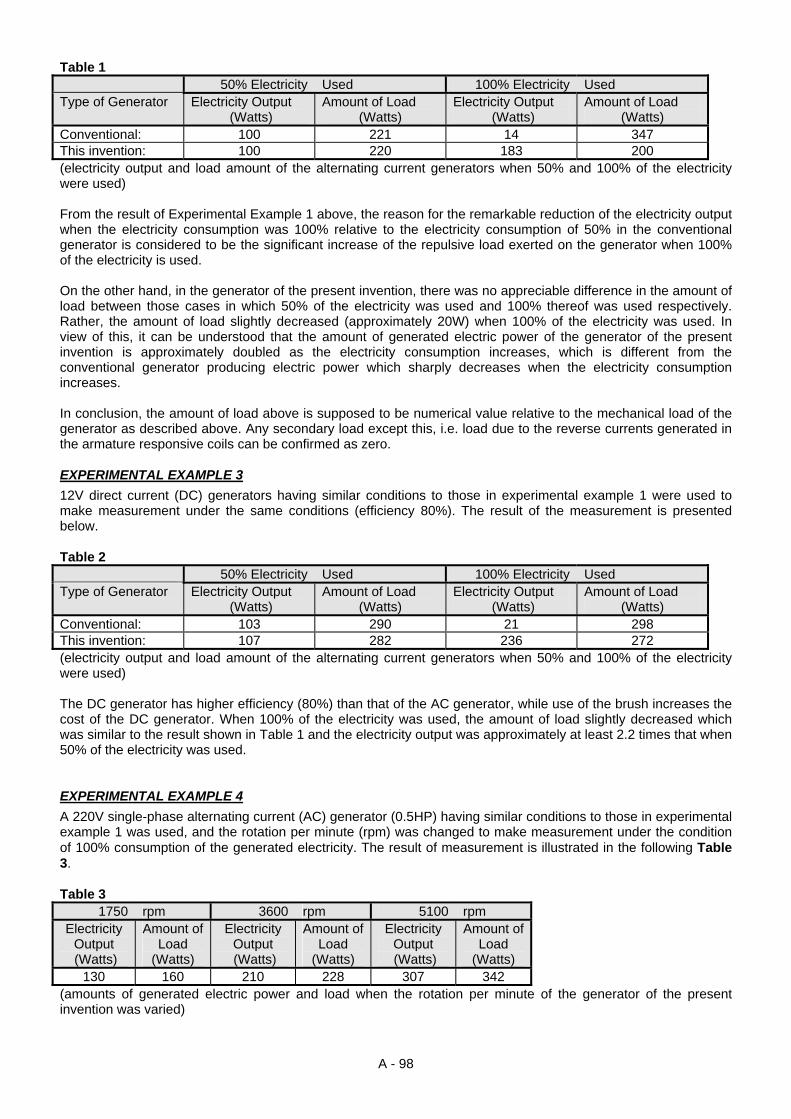
A - 98
Table 1 50% Electricity Used 100% Electricity Used Type of Generator Electricity Output
(Watts) Amount of Load
(Watts) Electricity Output
(Watts) Amount of Load
(Watts) Conventional: 100 221 14 347 This invention: 100 220 183 200 (electricity output and load amount of the alternating current generators when 50% and 100% of the electricity were used) From the result of Experimental Example 1 above, the reason for the remarkable reduction of the electricity output when the electricity consumption was 100% relative to the electricity consumption of 50% in the conventional generator is considered to be the significant increase of the repulsive load exerted on the generator when 100% of the electricity is used. On the other hand, in the generator of the present invention, there was no appreciable difference in the amount of load between those cases in which 50% of the electricity was used and 100% thereof was used respectively. Rather, the amount of load slightly decreased (approximately 20W) when 100% of the electricity was used. In view of this, it can be understood that the amount of generated electric power of the generator of the present invention is approximately doubled as the electricity consumption increases, which is different from the conventional generator producing electric power which sharply decreases when the electricity consumption increases. In conclusion, the amount of load above is supposed to be numerical value relative to the mechanical load of the generator as described above. Any secondary load except this, i.e. load due to the reverse currents generated in the armature responsive coils can be confirmed as zero. EXPERIMENTAL EXAMPLE 3 12V direct current (DC) generators having similar conditions to those in experimental example 1 were used to make measurement under the same conditions (efficiency 80%). The result of the measurement is presented below. Table 2 50% Electricity Used 100% Electricity Used Type of Generator Electricity Output
(Watts) Amount of Load
(Watts) Electricity Output
(Watts) Amount of Load
(Watts) Conventional: 103 290 21 298 This invention: 107 282 236 272 (electricity output and load amount of the alternating current generators when 50% and 100% of the electricity were used) The DC generator has higher efficiency (80%) than that of the AC generator, while use of the brush increases the cost of the DC generator. When 100% of the electricity was used, the amount of load slightly decreased which was similar to the result shown in Table 1 and the electricity output was approximately at least 2.2 times that when 50% of the electricity was used. EXPERIMENTAL EXAMPLE 4 A 220V single-phase alternating current (AC) generator (0.5HP) having similar conditions to those in experimental example 1 was used, and the rotation per minute (rpm) was changed to make measurement under the condition of 100% consumption of the generated electricity. The result of measurement is illustrated in the following Table 3. Table 3
1750 rpm 3600 rpm 5100 rpm Electricity
Output (Watts)
Amount of Load
(Watts)
Electricity Output (Watts)
Amount of Load
(Watts)
Electricity Output (Watts)
Amount of Load
(Watts) 130 160 210 228 307 342
(amounts of generated electric power and load when the rotation per minute of the generator of the present invention was varied)
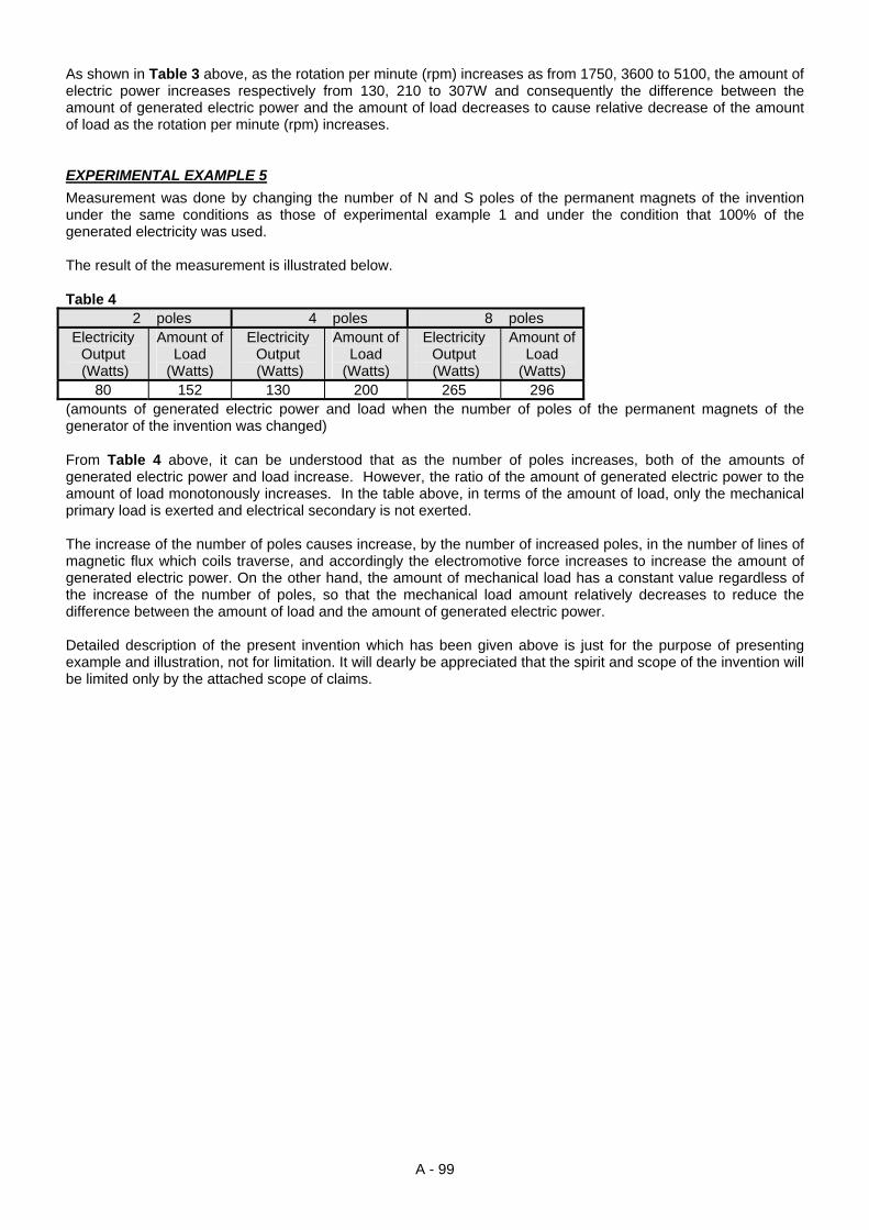
A - 99
As shown in Table 3 above, as the rotation per minute (rpm) increases as from 1750, 3600 to 5100, the amount of electric power increases respectively from 130, 210 to 307W and consequently the difference between the amount of generated electric power and the amount of load decreases to cause relative decrease of the amount of load as the rotation per minute (rpm) increases. EXPERIMENTAL EXAMPLE 5 Measurement was done by changing the number of N and S poles of the permanent magnets of the invention under the same conditions as those of experimental example 1 and under the condition that 100% of the generated electricity was used. The result of the measurement is illustrated below. Table 4
2 poles 4 poles 8 poles Electricity
Output (Watts)
Amount of Load
(Watts)
Electricity Output (Watts)
Amount of Load
(Watts)
Electricity Output (Watts)
Amount of Load
(Watts) 80 152 130 200 265 296
(amounts of generated electric power and load when the number of poles of the permanent magnets of the generator of the invention was changed) From Table 4 above, it can be understood that as the number of poles increases, both of the amounts of generated electric power and load increase. However, the ratio of the amount of generated electric power to the amount of load monotonously increases. In the table above, in terms of the amount of load, only the mechanical primary load is exerted and electrical secondary is not exerted. The increase of the number of poles causes increase, by the number of increased poles, in the number of lines of magnetic flux which coils traverse, and accordingly the electromotive force increases to increase the amount of generated electric power. On the other hand, the amount of mechanical load has a constant value regardless of the increase of the number of poles, so that the mechanical load amount relatively decreases to reduce the difference between the amount of load and the amount of generated electric power. Detailed description of the present invention which has been given above is just for the purpose of presenting example and illustration, not for limitation. It will dearly be appreciated that the spirit and scope of the invention will be limited only by the attached scope of claims.

A - 100
ALBERTO MOLINA-MARTINEZ: ELECTRICAL GENERATOR Patent Application US 20020125774 6th March 2002 Inventor: Alberto Molina-Martinez
CONTINUOUS ELECTRICAL GENERATOR
This patent application shows the details of a device which it is claimed, can produce sufficient electricity to power both itself and external loads. It also has no moving parts. ABSTRACT A stationary cylindrical electromagnetic core, made of one piece thin laminations stacked to desired height, having closed slots radially distributed, where two three-phase winding arrangements are placed together in the same slots, one to the centre, one to the exterior, for the purpose of creating a rotational electromagnetic field by temporarily applying a three-phase current to one of the windings, and by this means, inducting a voltage on the second one, in such a way that the outgoing energy is a lot greater than the input. A return will feedback the system and the temporary source is then disconnected. The generator will run by itself indefinitely, permanently generating a great excess of energy. BACKGROUND OF THE INVENTION 1. Field of the Invention The present invention relates generally to electrical power generating systems. More specifically, the present invention relates to self-feeding electrical power generating units. 2. Description of Related Art Since Nikola Tesla invented and patented his Polyphase System for Generators, Induction Motors and Transformers, no essential improvement has been made in the field. The generators would produce the polyphase voltages and currents by means of mechanical rotational movement in order to force a magnetic field to rotate across the generator's radially spaced windings. The basis of the induction motor system was to create an electro-magnetically rotating field, instead of a mechanically rotated magnetic field, which would induce voltages and currents to generate electromotive forces usable as mechanical energy or power. Finally, the transformers would manipulate the voltages and currents to make them feasible for their use and transmission for long distances. In all present Electric Generators a small amount of energy, normally less than one percent of the outgoing power in big generators, is used to excite the mechanically rotated electromagnetic poles that will induce voltages and currents in conductors having a relative speed or movement between them and the polar masses. The rest of the energy used in the process of obtaining electricity, is needed to move the masses and to overcome the losses of the system: mechanical losses; friction losses; brushes losses, windage losses; armature reaction losses; air gap losses; synchronous reactance losses; eddy current losses; hysteresis losses, all of which, in conjunction, are responsible for the excess in power input (mechanical power) required to generate always smaller amounts of electric power.

A - 101
SUMMARY OF THE INVENTION The Continuous Electrical Generator consists of a stationary cylindrical electromagnetic core made of one piece thin laminations stacked together to form a cylinder, where two three-phase windings arrangements are placed in the same slots not having any physical relative speed or displacement between them. When one of the windings is connected to a temporary three-phase source, an electromagnetic rotating field is created, and the field this way created will cut the stationary coils of the second winding, inducting voltages and currents. In the same way and extent as in common generators, about one percent or less of the outgoing power will be needed to keep the rotational magnetic field excited. In the Continuous Electrical Generator there are no mechanical losses; friction losses; brush losses; windage losses; armature reaction losses; or air gap losses, because there is not any movement of any kind. There are: synchronous reactance losses, eddy current losses and hysteresis losses, which are inherent to the design, construction and the materials of the generator, but in the same extent as in common generators. One percent or less of the total energy produced by present electric generators goes to create their own magnetic field; a mechanical energy that exceeds the total output of present generators is used to make them rotate in the process of extracting electrical currents from them. In the Continuous Electrical Generator there is no need for movement since the field is in fact already rotating electro-magnetically, so all that mechanical energy will not be needed. Under similar conditions of exciting currents, core mass and windings design, the Continuous Electrical Generator is significantly more efficient than present generators, which also means that it can produce significantly more than the energy it needs to operate. The Continuous Electrical Generator can feedback the system, the temporary source may be disconnected and the Generator will run indefinitely. As with any other generator, the Continuous Electrical Generator may excite its own electromagnetic field with a minimum part of the electrical energy produced. The Continuous Electrical Generator only needs to be started up by connecting its inducting three-phase windings to a three-phase external source for an instant, and then to be disconnected, to start the system as described herein. Then, disconnected, it will run indefinitely generating a great excess of electric power to the extent of its design. The Continuous Electrical Generator can be designed and calculated with all mathematical formulas in use today to design and calculate electrical generators and motors. It complies with all of the laws and parameters used to calculate electrical induction and generation of electricity today. Except for the Law of Conservation of Energy, which, by itself, is not a mathematical equation but a theoretical concept and by the same reason does not have any role in the mathematical calculation of an electrical generator of any type, the Continuous Electrical Generator complies with all the Laws of Physics and Electrical Engineering. The Continuous Electrical Generator obligates us to review the Law of Conservation of Energy. In my personal belief, the electricity has never come from the mechanical energy that we put into a machine to move the masses against all oppositions. The mechanical system is actually providing the path for the condensation of electricity. The Continuous Electrical Generator provides a more efficient path for the electricity.

A - 102
DESCRIPTION OF DRAWINGS Fig.1 shows one embodiment of the present invention.

A - 103
Fig.2 shows an internal wiring diagram for the embodiment of the present invention shown in Fig.1.
Fig.3 shows a single laminate for an alternate embodiment of the present invention.

A - 104
Fig.4 shows a two-piece single laminate for another alternate embodiment of the present invention.
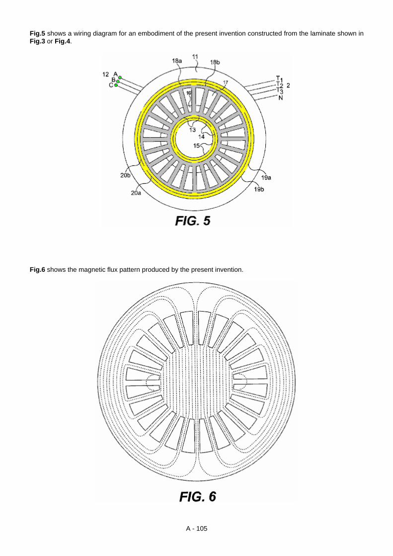
A - 105
Fig.5 shows a wiring diagram for an embodiment of the present invention constructed from the laminate shown in Fig.3 or Fig.4.
Fig.6 shows the magnetic flux pattern produced by the present invention.

A - 106
Fig.7 shows the rotational magnetic field patterns produced by the present invention.

A - 107
Fig.8 shows the complete system of the present invention.
Fig.9 is an expanded view of the alternate embodiment of the present invention shown in Fig.3 or Fig.4.
DETAILED DESCRIPTION OF THE INVENTION

A - 108
The present invention is a Continuous and Autonomous Electrical Generator, capable of producing more energy than it needs to operate, and which provides itself the energy needed to operate. The basic idea consists in the induction of electric voltages and currents without any physical movement by the use of a rotational magnetic field created by a three-phase stator connected temporarily to a three-phase source, and placing stationary conductors on the path of said rotational magnetic field, eliminating the need of mechanical forces.
The basic system can be observed in Fig.1, which shows one embodiment of the present invention. There is a stationary ferromagnetic core 1 with a three-phase inducting windings 3, spaced 120 degrees and connected in Y 6 in order to provide a rotating electromagnetic field, when a three-phase voltage is applied; for the case, a two-pole arrangement. Inside this core 1 there is a second stationary ferromagnetic core 2, with no space between them, this is, with no air-gap. This second core 2 has also a three-phase stationary winding arrangement (4a in Fig.4b and 4b in Fig.2), aligned as shown in Fig.1 and Fig.2 with the external core inducting windings 3. There is not any movement between the two cores, since there is no air-gap between them. There is no shaft on either core since these are not rotating cores. The two cores can be made of stacked insulated laminations or of insulated compressed and bonded ferromagnetic powder. The system works either way, inducting three-phase voltages and currents on the stationary conductors 4a of the internal windings 4b, applying three-phase currents to terminals A 5a, B 5b and C 5c of the external windings 3; or inducting three-phase voltages and currents on the external windings 3, by applying three-phase currents to the terminals T1 7a, T2 7b and T3 7c, of the internal windings 4b. When a three-phase voltage is applied to terminals A 5a, B 5b and C 5c, the currents will have the same magnitude, but will be displaced in time by an angle of 120 degrees. These currents produce magneto motive-forces, which, in turn, create a rotational magnetic flux. The arrangements may vary widely as they occur with present alternators and three-phase motors, but the basics remain the same, a stationary but electro-magnetically rotating magnetic field, inducting voltages and currents on the stationary conductors placed on the path of said rotating magnetic field. The diagram is showing a two-pole arrangement for both windings, but many other arrangements may be used, as in common generators and motors.
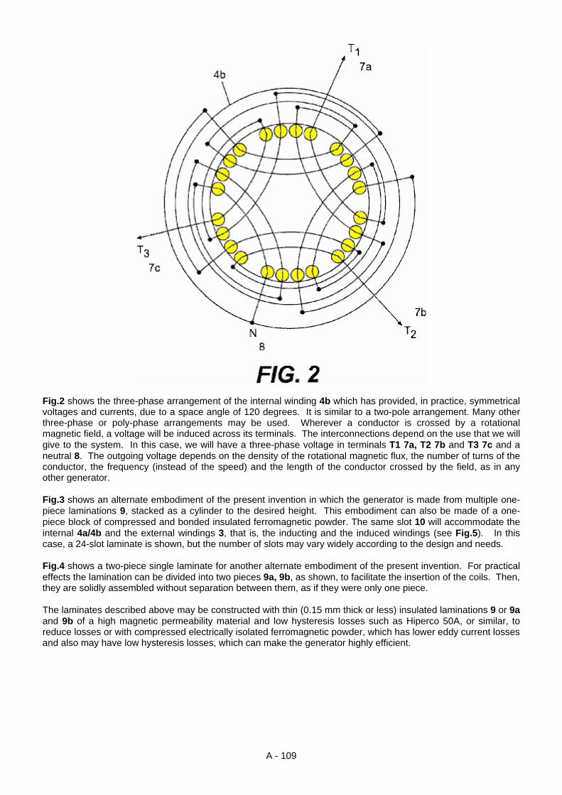
A - 109
Fig.2 shows the three-phase arrangement of the internal winding 4b which has provided, in practice, symmetrical voltages and currents, due to a space angle of 120 degrees. It is similar to a two-pole arrangement. Many other three-phase or poly-phase arrangements may be used. Wherever a conductor is crossed by a rotational magnetic field, a voltage will be induced across its terminals. The interconnections depend on the use that we will give to the system. In this case, we will have a three-phase voltage in terminals T1 7a, T2 7b and T3 7c and a neutral 8. The outgoing voltage depends on the density of the rotational magnetic flux, the number of turns of the conductor, the frequency (instead of the speed) and the length of the conductor crossed by the field, as in any other generator. Fig.3 shows an alternate embodiment of the present invention in which the generator is made from multiple one-piece laminations 9, stacked as a cylinder to the desired height. This embodiment can also be made of a one-piece block of compressed and bonded insulated ferromagnetic powder. The same slot 10 will accommodate the internal 4a/4b and the external windings 3, that is, the inducting and the induced windings (see Fig.5). In this case, a 24-slot laminate is shown, but the number of slots may vary widely according to the design and needs. Fig.4 shows a two-piece single laminate for another alternate embodiment of the present invention. For practical effects the lamination can be divided into two pieces 9a, 9b, as shown, to facilitate the insertion of the coils. Then, they are solidly assembled without separation between them, as if they were only one piece. The laminates described above may be constructed with thin (0.15 mm thick or less) insulated laminations 9 or 9a and 9b of a high magnetic permeability material and low hysteresis losses such as Hiperco 50A, or similar, to reduce losses or with compressed electrically isolated ferromagnetic powder, which has lower eddy current losses and also may have low hysteresis losses, which can make the generator highly efficient.

A - 110
OPERATING THE GENERATOR The Continuous Electrical Generator as described and shown in the following drawings is designed and calculated to produce a strong rotating electromagnetic field with low exciting currents. By using a laminated material, such as the said Hiperco 50A, we can achieve rotating magnetic fields above two Teslas, since there are no air gap losses, mechanical losses, windage losses, armature reaction losses, etc. as said before. This may be obtained by applying a temporary three-phase current to the terminals A, B and C 12 of the inducting coils 13, 14 and 15 (5a, 5b and 5c in Fig.1), spaced 120 degrees from each other (see Fig.5).
Fig.5 shows the spatial distribution of the inducting windings 13, 14 and 15, as well as the induced windings 18a, 18b, 19a, 19b, 20a and 20b. Both, the inducting and the induced windings are placed in the same slots 10 or 16 and 17, with similar arrangements. Even though the system works in both directions, the better configuration seems to be to place the inducting windings 13, 14 and 15, to the centre and the induced windings 18a, 18b, 19a, 19b, 20a and 20b, to the exterior, since small windings will be needed to induce a very strong rotational magnetic field, due to the small losses involved in the process, and in exchange, bigger and powerful windings will be needed to extract all the energy that the system will provide. Both windings are connected in Y (not shown), but they can be connected in different ways, as any other generator. These arrangements are equivalent to the arrangements shown for the embodiment in Fig.1 and Fig.2. The inducting coils 13, 14 and 15 are designed and calculated so that the generator may be started with common three-phase lines voltages (230 Volts 60 Hz per phase, for example). If the local lines voltages are not appropriate, we can control the voltage to the designed level by means of a three-phase variable transformer, an electronic variator or inverter etc. Once we have such strong magnetic field rotating and crossing the stationary induced coils 18a, 18b, 19a, 19b, 20a and 20b, a three-phase voltage will be induced across terminals T1, T2, T3 and N 21 in proportion to the magnetic flux density, the number of turns in the coils, the frequency used (instead of the speed), the length of the conductors cut by the rotating field, as in any other alternator. We can connect, as we desire in Y or delta, etc., as in any other alternator or generator. The outgoing currents will be three-phase currents (or poly-phase currents depending on the arrangement) and we can have a neutral 21 if we are using a Y connection, as in any other alternator. The outgoing alternate voltages and currents are perfect sinusoidal waves, perfectly spaced in time, and totally symmetrical. The voltages and currents obtained by this method are usable in any conventional manner. Any voltage can be produced, depending on the design. Fig.6 shows the magnetic flux pattern produced by the three-phase inducting windings 13, 14 and 15. This pattern is similar to the pattern of an induction motor's stators. Since there is no air gap; the whole path for the magnetic flux is homogeneous with no change in materials. The core is made of thin insulated laminations of a high magnetic permeability and low hysteresis loss material; eddy current losses are minimal due to the thin lamination. There are no counter fluxes or armature reactions thus the magnetic flux may be near to saturation with a small exciting current or input energy. Due to the time differential between the three phases and the spatial distribution of the inducting windings, a rotational magnetic field will be created in the core, as shown in Fig.7.
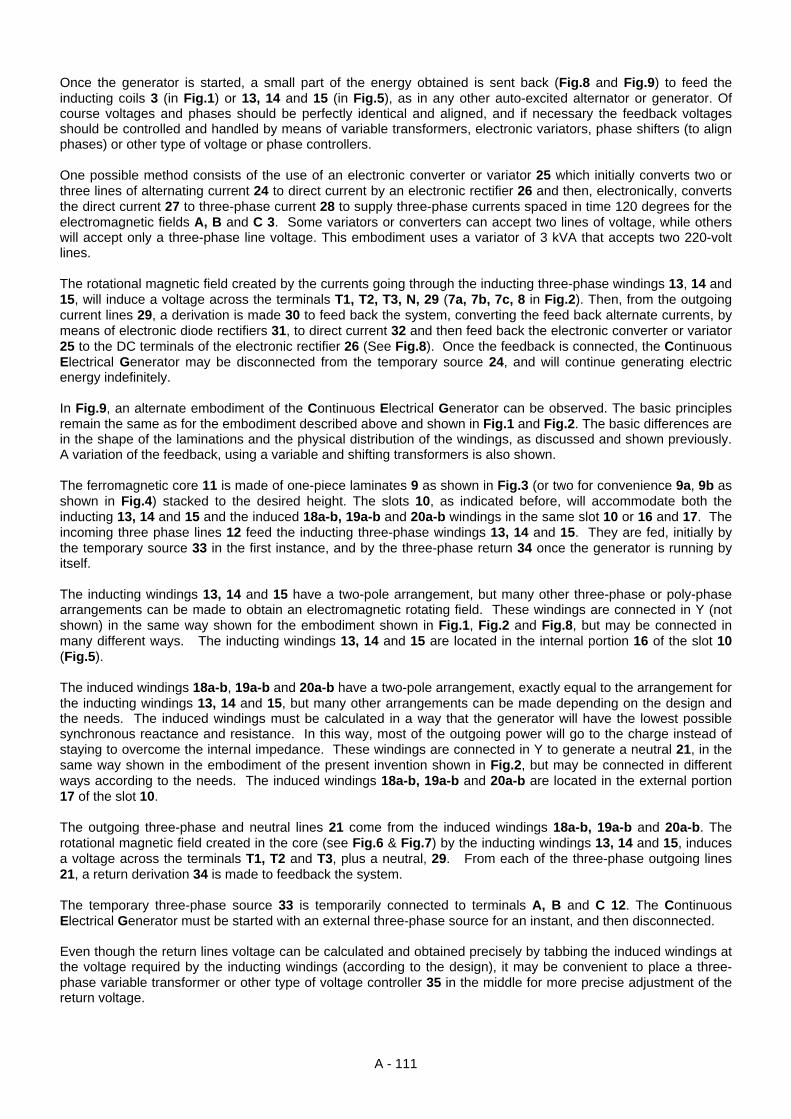
A - 111
Once the generator is started, a small part of the energy obtained is sent back (Fig.8 and Fig.9) to feed the inducting coils 3 (in Fig.1) or 13, 14 and 15 (in Fig.5), as in any other auto-excited alternator or generator. Of course voltages and phases should be perfectly identical and aligned, and if necessary the feedback voltages should be controlled and handled by means of variable transformers, electronic variators, phase shifters (to align phases) or other type of voltage or phase controllers. One possible method consists of the use of an electronic converter or variator 25 which initially converts two or three lines of alternating current 24 to direct current by an electronic rectifier 26 and then, electronically, converts the direct current 27 to three-phase current 28 to supply three-phase currents spaced in time 120 degrees for the electromagnetic fields A, B and C 3. Some variators or converters can accept two lines of voltage, while others will accept only a three-phase line voltage. This embodiment uses a variator of 3 kVA that accepts two 220-volt lines. The rotational magnetic field created by the currents going through the inducting three-phase windings 13, 14 and 15, will induce a voltage across the terminals T1, T2, T3, N, 29 (7a, 7b, 7c, 8 in Fig.2). Then, from the outgoing current lines 29, a derivation is made 30 to feed back the system, converting the feed back alternate currents, by means of electronic diode rectifiers 31, to direct current 32 and then feed back the electronic converter or variator 25 to the DC terminals of the electronic rectifier 26 (See Fig.8). Once the feedback is connected, the Continuous Electrical Generator may be disconnected from the temporary source 24, and will continue generating electric energy indefinitely. In Fig.9, an alternate embodiment of the Continuous Electrical Generator can be observed. The basic principles remain the same as for the embodiment described above and shown in Fig.1 and Fig.2. The basic differences are in the shape of the laminations and the physical distribution of the windings, as discussed and shown previously. A variation of the feedback, using a variable and shifting transformers is also shown. The ferromagnetic core 11 is made of one-piece laminates 9 as shown in Fig.3 (or two for convenience 9a, 9b as shown in Fig.4) stacked to the desired height. The slots 10, as indicated before, will accommodate both the inducting 13, 14 and 15 and the induced 18a-b, 19a-b and 20a-b windings in the same slot 10 or 16 and 17. The incoming three phase lines 12 feed the inducting three-phase windings 13, 14 and 15. They are fed, initially by the temporary source 33 in the first instance, and by the three-phase return 34 once the generator is running by itself. The inducting windings 13, 14 and 15 have a two-pole arrangement, but many other three-phase or poly-phase arrangements can be made to obtain an electromagnetic rotating field. These windings are connected in Y (not shown) in the same way shown for the embodiment shown in Fig.1, Fig.2 and Fig.8, but may be connected in many different ways. The inducting windings 13, 14 and 15 are located in the internal portion 16 of the slot 10 (Fig.5). The induced windings 18a-b, 19a-b and 20a-b have a two-pole arrangement, exactly equal to the arrangement for the inducting windings 13, 14 and 15, but many other arrangements can be made depending on the design and the needs. The induced windings must be calculated in a way that the generator will have the lowest possible synchronous reactance and resistance. In this way, most of the outgoing power will go to the charge instead of staying to overcome the internal impedance. These windings are connected in Y to generate a neutral 21, in the same way shown in the embodiment of the present invention shown in Fig.2, but may be connected in different ways according to the needs. The induced windings 18a-b, 19a-b and 20a-b are located in the external portion 17 of the slot 10. The outgoing three-phase and neutral lines 21 come from the induced windings 18a-b, 19a-b and 20a-b. The rotational magnetic field created in the core (see Fig.6 & Fig.7) by the inducting windings 13, 14 and 15, induces a voltage across the terminals T1, T2 and T3, plus a neutral, 29. From each of the three-phase outgoing lines 21, a return derivation 34 is made to feedback the system. The temporary three-phase source 33 is temporarily connected to terminals A, B and C 12. The Continuous Electrical Generator must be started with an external three-phase source for an instant, and then disconnected. Even though the return lines voltage can be calculated and obtained precisely by tabbing the induced windings at the voltage required by the inducting windings (according to the design), it may be convenient to place a three-phase variable transformer or other type of voltage controller 35 in the middle for more precise adjustment of the return voltage.

A - 112
Placed after the variable transformer 35, the three-phase shifting transformer 36 will correct and align any phase shift in the voltage and currents angles, before the return is connected. This system functions similarly to the system shown in Fig.8 which uses a variator or a converter 25. Once the voltage and phases are aligned with the temporary source 33, the return lines 34 are connected to the incoming lines A, B and C 12 at feedback connection 37 and the temporary source 33 is then disconnected. The Continuous Electrical Generator will remain working indefinitely without any external source of energy, providing a great excess of energy permanently. The outgoing electric energy provided by this system has been used to produce light and heat, run poly-phase motors, generate usable mono-phase and poly-phase voltages and currents, transform voltages and currents by means of transformers, convert the alternate outgoing poly-phase currents to direct current, as well as for other uses. The electricity obtained by the means described is as versatile and perfect as the electricity obtained today with common electric generators. But the Continuous Electrical Generator is autonomous and does not depend on any other source of energy but itself once it is running; may be carried anywhere with no limitations; it can be constructed in any size and provides any amount of electricity indefinitely, according to the design. The Continuous Electrical Generator is and will be a very simple machine. The keystones of the systems reside in the ultra-low losses of a non-movement generation system, and in a very low synchronous reactance design. The induced windings must be calculated in a way that the generator may have the lowest possible synchronous reactance and resistance. In this way, most of the outgoing power will go to the charge instead of staying to overcome the internal impedance.

A - 113
MICHAEL OGNYANOV: SEMICONDUCTORS Patent Application US 3,766,094 20th September 1971 Inventor: Michael Ognyanov
SEMICONDUCTOR COMPOSITIONS This patent application shows the details of a device which it is claimed, can produce electricity via a solid-state oscillator. It should be noted that while construction details are provided which imply that the inventor constructed and tested several of these devices, this is only an application and not a granted patent. ABSTRACT A resonance oscillator electric power pack for operating a flash lamp, for example, or other electrically operated device, operates without moving mechanical parts or electrolytic action. The power pack is contained in a cylindrical metal envelope and in a preferred embodiment, is coupled to a relaxation oscillator and an incandescent lamp. Within the envelope, and insulated from it, is a semiconductor tablet having a metal base connected to the external circuit. A metal probe makes contact with a point on the semiconductor tablet and with a cylindrical ferrite rod, axially aligned with the envelope. Wound about the ferrite rod, are concentric helical coils designated as a ‘primary’ with many turns, and a ‘secondary’ with fewer turns than the primary. One end of the primary coil is connected to the probe and the other end is connected to the secondary coil. the leads from the secondary coil are connected to the relaxation oscillator via an adjustable capacitor. Oscillation within the envelope is resonance amplified , and the induced voltage in the secondary coil is rectified for application to the relaxation oscillator and lamp. Selenium and germanium base semiconductor compositions including Te, Nd, Rb and Ga in varying proportions area used for the tablet. BACKGROUND OF THE INVENTION This is a continuation-in-part of my co-pending patent application Serial No. 77,452, filed 2nd October 1970, entitled “Electric Power Pack” now abandoned. In many situations it is desirable to have a source of electric power which is not dependent on wires from a central generating station, and therefore, portable power supplies having no moving parts have been employed. typically, such portable power packs have been primary or secondary electrolytic cells which generate or store electrical energy for release by chemical action. Such batteries have a limited amount of contained energy and must often be replaced at frequent intervals to maintain equipment in operation. Thus, as one example, flashing lights are commonly used along highways and other locations to warn of dangerous conditions. These flashing lights in remote locations are typically incandescent or gas-discharge lamps connected to some type of relaxation oscillator powered by a battery. The batteries employed in such blinking lights have a limited lifetime and must be periodically replaced, typically each 250 to 300 hours of operation. This involves a rather large labour cost in replacing the expended batteries with fresh ones and additional cost for primary cells or for recharging secondary cells. It is desirable to provide an electric power pack capable of providing a sufficient quantity of electrical energy over a prolonged period of time so that the requirement for periodic replacement of the electrolytic cells can be avoided. Such a power pack is valuable even if appreciably more expensive than batteries because of the greatly reduced labour costs required for periodic replacements. BRIEF SUMMARY OF THE INVENTION There is provided in practice of this invention according to a preferred embodiment, semiconductive compositions selected from the Group consisting of: Selenium with, from 4.85% to 5.5% Tellurium, from 3.95% to 4.2% Germanium, from 2.85% to 3.2% Neodymium, and from 2.0% to 2.5% Gallium. Selenium with, from 4.8% to 5.5% Tellurium, from 3.9% to 4.5% Germanium, from 2.9% to 3.5% Neodymium and from 4.5% to 5% Rubidium, and Germanium with, from 4.75% to 5.5% Tellurium, from 4.0% to 4.5% Neodymium and from 5.5% to 7.0% Rubidium.
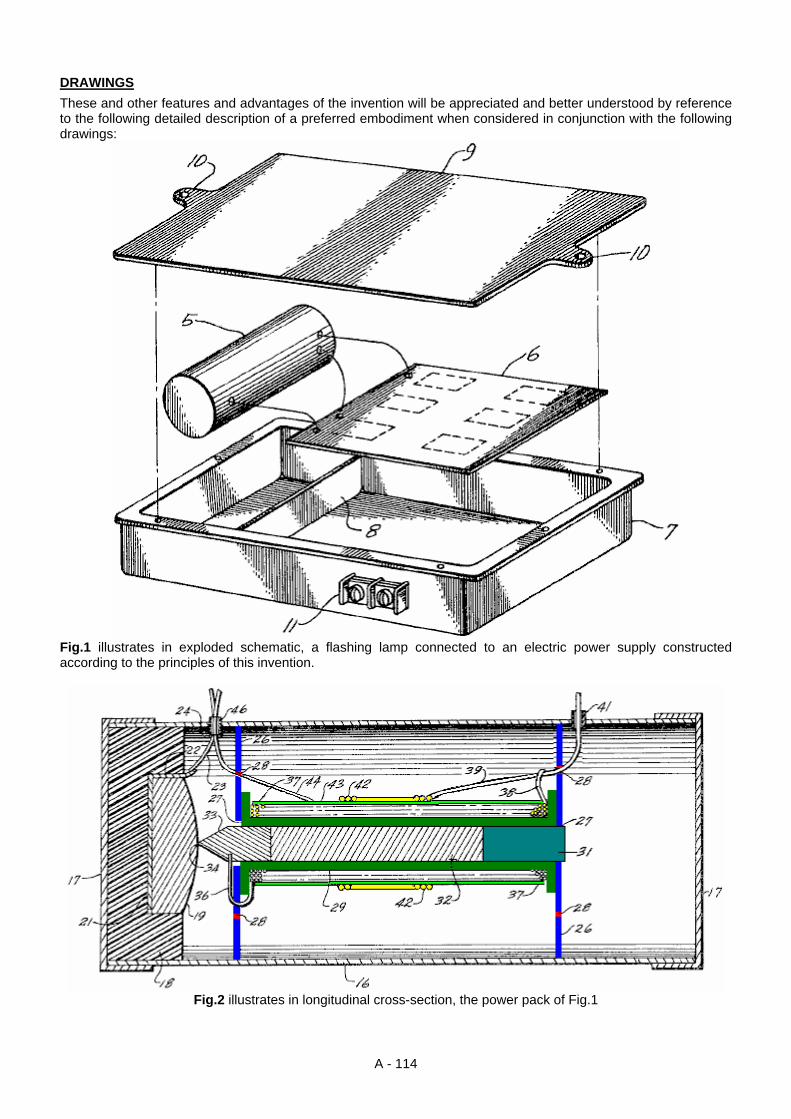
A - 114
DRAWINGS These and other features and advantages of the invention will be appreciated and better understood by reference to the following detailed description of a preferred embodiment when considered in conjunction with the following drawings:
Fig.1 illustrates in exploded schematic, a flashing lamp connected to an electric power supply constructed according to the principles of this invention.
Fig.2 illustrates in longitudinal cross-section, the power pack of Fig.1
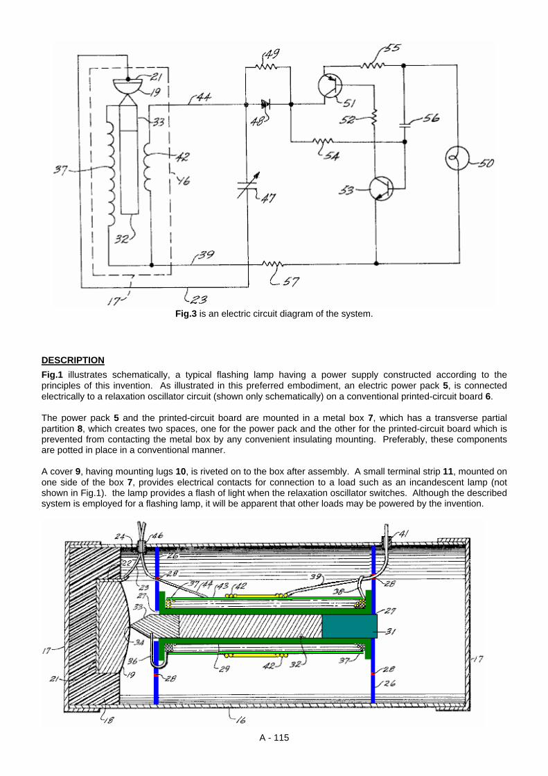
A - 115
Fig.3 is an electric circuit diagram of the system.
DESCRIPTION Fig.1 illustrates schematically, a typical flashing lamp having a power supply constructed according to the principles of this invention. As illustrated in this preferred embodiment, an electric power pack 5, is connected electrically to a relaxation oscillator circuit (shown only schematically) on a conventional printed-circuit board 6. The power pack 5 and the printed-circuit board are mounted in a metal box 7, which has a transverse partial partition 8, which creates two spaces, one for the power pack and the other for the printed-circuit board which is prevented from contacting the metal box by any convenient insulating mounting. Preferably, these components are potted in place in a conventional manner. A cover 9, having mounting lugs 10, is riveted on to the box after assembly. A small terminal strip 11, mounted on one side of the box 7, provides electrical contacts for connection to a load such as an incandescent lamp (not shown in Fig.1). the lamp provides a flash of light when the relaxation oscillator switches. Although the described system is employed for a flashing lamp, it will be apparent that other loads may be powered by the invention.
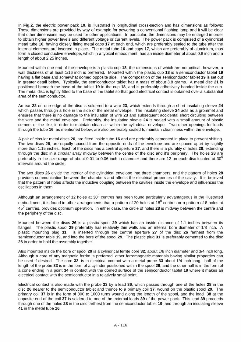
A - 116
In Fig.2, the electric power pack 10, is illustrated in longitudinal cross-section and has dimensions as follows: These dimensions are provided by way of example for powering a conventional flashing lamp and it will be clear that other dimensions may be used for other applications. In particular, the dimensions may be enlarged in order to obtain higher power levels and different voltage or current levels. The power pack is comprised of a cylindrical metal tube 16, having closely fitting metal caps 17 at each end, which are preferably sealed to the tube after the internal elements are inserted in place. The metal tube 16 and caps 17, which are preferably of aluminium, thus form a closed conductive envelope, which in a typical embodiment, has an inside diameter of about 0.8 inch and a length of about 2.25 inches. Mounted within one end of the envelope is a plastic cup 18, the dimensions of which are not critical, however, a wall thickness of at least 1/16 inch is preferred. Mounted within the plastic cup 18 is a semiconductor tablet 19 having a flat base and somewhat domed opposite side. The composition of the semiconductor tablet 19 is set out in greater detail below. Typically, the semiconductor tablet has a mass of about 3.8 grams. A metal disc 21 is positioned beneath the base of the tablet 19 in the cup 18, and is preferably adhesively bonded inside the cup. The metal disc is tightly fitted to the base of the tablet so that good electrical contact is obtained over a substantial area of the semiconductor. An ear 22 on one edge of the disc is soldered to a wire 23, which extends through a short insulating sleeve 24 which passes through a hole in the side of the metal envelope. The insulating sleeve 24 acts as a grommet and ensures that there is no damage to the insulation of wire 23 and subsequent accidental short circuiting between the wire and the metal envelope. Preferably, the insulating sleeve 24 is sealed with a small amount of plastic cement or the like, in order to maintain clean air within the cylindrical envelope. Two other openings for leads through the tube 16, as mentioned below, are also preferably sealed to maintain cleanliness within the envelope. A pair of circular metal discs 26, are fitted inside tube 16 and are preferably cemented in place to prevent shifting. The two discs 26, are equally spaced from the opposite ends of the envelope and are spaced apart by slightly more than 1.15 inches. Each of the discs has a central aperture 27, and there is a plurality of holes 28, extending through the disc in a circular array midway between the centre of the disc and it’s periphery. The holes 28 are preferably in the size range of about 0.01 to 0.06 inch in diameter and there are 12 on each disc located at 300
intervals around the circle. The two discs 26 divide the interior of the cylindrical envelope into three chambers, and the pattern of holes 28 provides communication between the chambers and affects the electrical properties of the cavity. It is believed that the pattern of holes affects the inductive coupling between the cavities inside the envelope and influences the oscillations in them. Although an arrangement of 12 holes at 300 centres has been found particularly advantageous in the illustrated embodiment, it is found in other arrangements that a pattern of 20 holes at 180 centres or a pattern of 8 holes at 450 centres, provides optimum operation. In either case, the circle of holes 28 is midway between the centre and the periphery of the disc. Mounted between the discs 26 is a plastic spool 29 which has an inside distance of 1.1 inches between its flanges. The plastic spool 29 preferably has relatively thin walls and an internal bore diameter of 1/8 inch. A plastic mounting plug 31, is inserted through the central aperture 27 of the disc 26 farthest from the semiconductor table 19, and into the bore of the spool 29. The plastic plug 31 is preferably cemented to the disc 26 in order to hold the assembly together. Also mounted inside the bore of spool 29 is a cylindrical ferrite core 32, about 1/8 inch diameter and 3/4 inch long. Although a core of any magnetic ferrite is preferred, other ferromagnetic materials having similar properties can be used if desired. The core 32, is in electrical contact with a metal probe 33 about 1/4 inch long. half of the length of the probe 33 is in the form of a cylinder positioned within the spool 29, and the other half is in the form of a cone ending in a point 34 in contact with the domed surface of the semiconductor tablet 19 where it makes an electrical contact with the semiconductor in a relatively small point. Electrical contact is also made with the probe 33 by a lead 36, which passes through one of the holes 28 in the disc 26 nearer to the semiconductor tablet and thence to a primary coil 37, wound on the plastic spool 29. The primary coil 37 is in the form of 800 to 1000 turns wound along the length of the spool, and the lead 38 at the opposite end of the coil 37 is soldered to one of the external leads 39 of the power pack. This lead 39 proceeds through one of the holes 28 in the disc farthest from the semiconductor tablet 19, and through an insulating sleeve 41 in the metal tube 16.
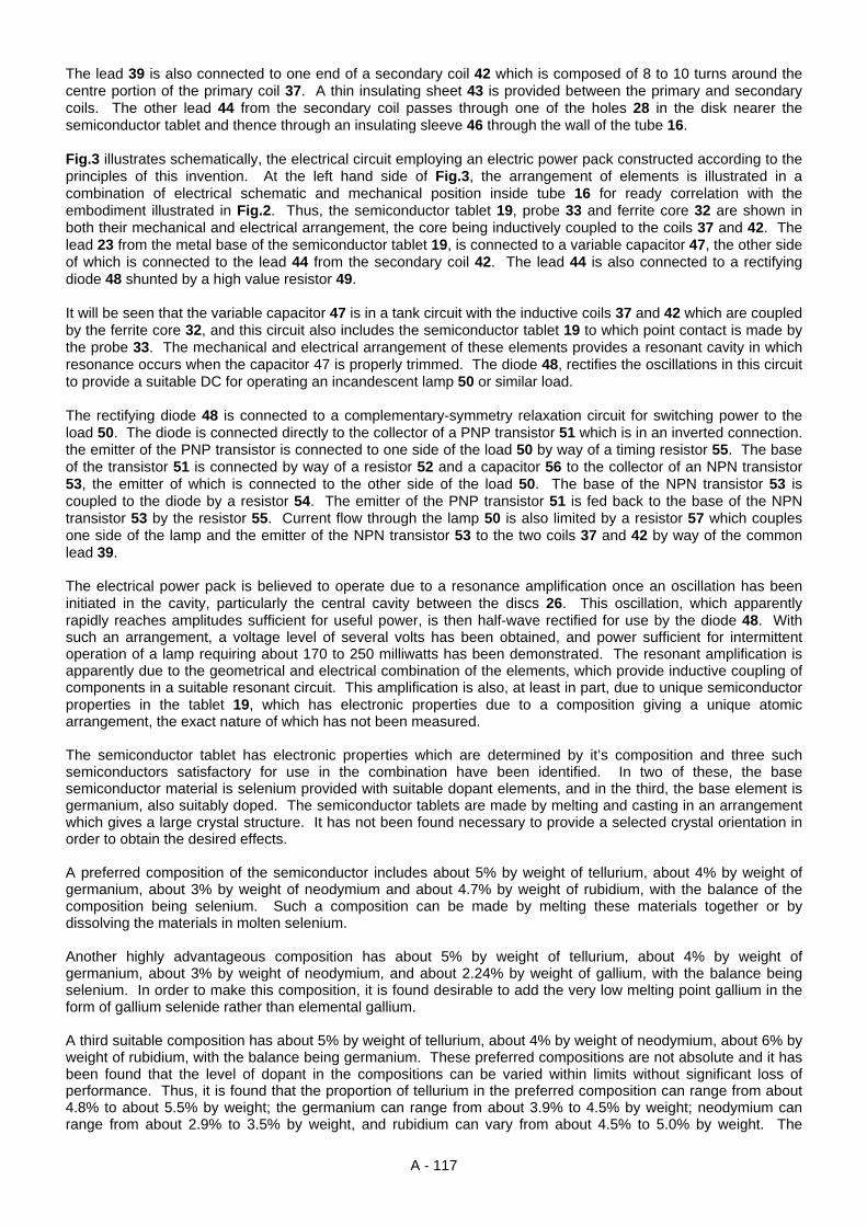
A - 117
The lead 39 is also connected to one end of a secondary coil 42 which is composed of 8 to 10 turns around the centre portion of the primary coil 37. A thin insulating sheet 43 is provided between the primary and secondary coils. The other lead 44 from the secondary coil passes through one of the holes 28 in the disk nearer the semiconductor tablet and thence through an insulating sleeve 46 through the wall of the tube 16. Fig.3 illustrates schematically, the electrical circuit employing an electric power pack constructed according to the principles of this invention. At the left hand side of Fig.3, the arrangement of elements is illustrated in a combination of electrical schematic and mechanical position inside tube 16 for ready correlation with the embodiment illustrated in Fig.2. Thus, the semiconductor tablet 19, probe 33 and ferrite core 32 are shown in both their mechanical and electrical arrangement, the core being inductively coupled to the coils 37 and 42. The lead 23 from the metal base of the semiconductor tablet 19, is connected to a variable capacitor 47, the other side of which is connected to the lead 44 from the secondary coil 42. The lead 44 is also connected to a rectifying diode 48 shunted by a high value resistor 49. It will be seen that the variable capacitor 47 is in a tank circuit with the inductive coils 37 and 42 which are coupled by the ferrite core 32, and this circuit also includes the semiconductor tablet 19 to which point contact is made by the probe 33. The mechanical and electrical arrangement of these elements provides a resonant cavity in which resonance occurs when the capacitor 47 is properly trimmed. The diode 48, rectifies the oscillations in this circuit to provide a suitable DC for operating an incandescent lamp 50 or similar load. The rectifying diode 48 is connected to a complementary-symmetry relaxation circuit for switching power to the load 50. The diode is connected directly to the collector of a PNP transistor 51 which is in an inverted connection. the emitter of the PNP transistor is connected to one side of the load 50 by way of a timing resistor 55. The base of the transistor 51 is connected by way of a resistor 52 and a capacitor 56 to the collector of an NPN transistor 53, the emitter of which is connected to the other side of the load 50. The base of the NPN transistor 53 is coupled to the diode by a resistor 54. The emitter of the PNP transistor 51 is fed back to the base of the NPN transistor 53 by the resistor 55. Current flow through the lamp 50 is also limited by a resistor 57 which couples one side of the lamp and the emitter of the NPN transistor 53 to the two coils 37 and 42 by way of the common lead 39. The electrical power pack is believed to operate due to a resonance amplification once an oscillation has been initiated in the cavity, particularly the central cavity between the discs 26. This oscillation, which apparently rapidly reaches amplitudes sufficient for useful power, is then half-wave rectified for use by the diode 48. With such an arrangement, a voltage level of several volts has been obtained, and power sufficient for intermittent operation of a lamp requiring about 170 to 250 milliwatts has been demonstrated. The resonant amplification is apparently due to the geometrical and electrical combination of the elements, which provide inductive coupling of components in a suitable resonant circuit. This amplification is also, at least in part, due to unique semiconductor properties in the tablet 19, which has electronic properties due to a composition giving a unique atomic arrangement, the exact nature of which has not been measured. The semiconductor tablet has electronic properties which are determined by it’s composition and three such semiconductors satisfactory for use in the combination have been identified. In two of these, the base semiconductor material is selenium provided with suitable dopant elements, and in the third, the base element is germanium, also suitably doped. The semiconductor tablets are made by melting and casting in an arrangement which gives a large crystal structure. It has not been found necessary to provide a selected crystal orientation in order to obtain the desired effects. A preferred composition of the semiconductor includes about 5% by weight of tellurium, about 4% by weight of germanium, about 3% by weight of neodymium and about 4.7% by weight of rubidium, with the balance of the composition being selenium. Such a composition can be made by melting these materials together or by dissolving the materials in molten selenium. Another highly advantageous composition has about 5% by weight of tellurium, about 4% by weight of germanium, about 3% by weight of neodymium, and about 2.24% by weight of gallium, with the balance being selenium. In order to make this composition, it is found desirable to add the very low melting point gallium in the form of gallium selenide rather than elemental gallium. A third suitable composition has about 5% by weight of tellurium, about 4% by weight of neodymium, about 6% by weight of rubidium, with the balance being germanium. These preferred compositions are not absolute and it has been found that the level of dopant in the compositions can be varied within limits without significant loss of performance. Thus, it is found that the proportion of tellurium in the preferred composition can range from about 4.8% to about 5.5% by weight; the germanium can range from about 3.9% to 4.5% by weight; neodymium can range from about 2.9% to 3.5% by weight, and rubidium can vary from about 4.5% to 5.0% by weight. The
A - 118
balance of the preferred composition is selenium although it has also been found that nominal impurity levels can be tolerated and no great care is required in preventing minor contamination. The other selenium base composition useful in practice of this invention can have a tellurium concentration in the range of from about 4.85% to 5.5% by weight, germanium in the range of from about 3.95% to 4.2% by weight, neodymium in the range of from about 2.85% to 3.2% by weight, and gallium in the range of from about 2.0% to 2.5% by weight. As in the preferred composition, the balance is selenium and nominal impurity levels can be tolerated. It is preferred to add the gallium in the form of gallium selenide rather than as elemental gallium with a corresponding decrease in the selenium used to make up the composition. The above selenium base compositions are easier to make and less expensive than the germanium base composition and are therefore preferable for most applications. It is found that these are particularly suited for relatively small semiconductor tablets up to about 1 inch or a little less. For relatively large tablets, it is preferred to use the germanium base composition. The germanium base composition has a tellurium level in the range of from about 4.75% to 5.5% by weight, neodymium in the range of from about 4.0% to 4.5% by weight, and rubidium in the range of from about 5.5% to 7.4% by weight. It is also found that it is of greater importance to maintain purity of the germanium base compositions than the selenium base compositions. Although the exact purity levels have not been ascertained, it is in excess of 99%. It has been found that it is not necessary to have single crystals in the semiconductor tablets and any convenient grain size in excess of about 1 millimetre appears satisfactory. In the above compositions, when the recited ranges are exceeded, oscillation in the power pack drops off rapidly and may cease altogether. The reasons that these compositions are satisfactory in the arrangement providing resonance amplification has not been determined with certainty. It is possible that the semiconductor serves as a source of electrons for providing an oscillating current in the circuit. This is, of course, combined with a relatively large area contact to one side of the semiconductor tablet, and a point contact on another area. Any resonant current in the coils wound on the ferrite rod, induces a varying magnetic field in the resonant cavity, and the electrical connection between the ferrite rod and the metal probe, provides a feedback of this oscillation to the semiconductor tablet. it should particularly be noted that the oscillation in the circuit does not commence until it is initiated by an oscillating signal. In order to accomplish this, it is only necessary to apply a few millivolts of AC for a few seconds to the semiconductor tablet and the associated coils coupled to it. The initial signal applied to the base of the semiconductor tablet and the lead 39 is preferably in the frequency range of 5.8 to 18 Mhz and can be as high as 150 Mhz. Such a signal can be applied from any conventional source and no great care appears necessary to provide a single frequency signal or to eliminate noise. Once such energisation has been applied to the circuit and oscillations initiated, it does not appear to be necessary to apply such a signal again. This is apparently due to the feedback provided by the ferrite rod to the probe which makes contact with the semiconductor tablet. Energy is, of course, dissipated in the lamp, or other utilisation device, as the combination operates. Such energy may come from deterioration of the semiconductor tablet as oscillations continue; however, if there is any such deterioration, it is sufficiently slow that a power source may be operated for many months without attendance. Such a source of energy may be augmented by ambient Radio Frequency radiation, coupled into the resonant cavity by the external leads. This is a surprising phenomenon because the leads are small compared to what would normally be considered an adequate antenna, and it is therefore postulated that stimulated amplification may also be a consequence of the unique electronic configuration of the semiconductors having the compositions specified above. Although only one embodiment of electric power pack constructed according to principles of this invention has been described and illustrated here, many modifications and variations will be apparent to one skilled in the art. Thus, for example, a larger power pack may be axially arranged in a cylindrical container with various electronic elements arranged in the annular space. It is therefore to be understood that other configurations are included within the scope of the invention.

A - 119
EDWIN GRAY: ELECTRIC MOTOR
US Patent 3,890,548 June 17, 1975 Inventor: Edwin V. Gray snr.
PULSED CAPACITOR DISCHARGE ELECTRIC ENGINE
Please note that this is a re-worded extract from Edwin Gray’s Patent 3,890,548. It describes his high voltage motor and the circuitry used to drive it. Please be aware that the underlying technology was developed by Marvin Cole and Edwin Gray did not understand it. Also, Edwin wanted at all costs to conceal any useful technology while getting patents to encourage investors, so please understand that this patent is not intended to tell you how to make a working system of this type. SUMMARY OF THE INVENTION: This invention relates to electric motors or engines, and more particularly to a new electric machine including electromagnetic poles in a stator configuration and electromagnetic poles in a rotor configuration, wherein in one form thereof, the rotor is rotatable within the stator configuration and where both are energised by capacitor discharges through rotor and stator electromagnets at the instant of the alignment of a rotor electromagnet with a stator electromagnet. The rotor electromagnet is repelled from the stator electromagnet by the discharge of the capacitor through the coils of both the rotor and stator electromagnets at the same instant. In an exemplary rotary engine according to this invention, rotor electromagnets may be disposed 120 degrees apart on a central shaft and major stator electromagnets may be disposed 40 degrees apart in the motor housing about the stator periphery. Other combinations of rotor elements and stator elements may be utilised to increase torque or rate of rotation. In another form, a second electromagnet is positioned to one side of each of the major stator electromagnets on a centreline 13.5 degrees from the centreline of the stator magnet, and these are excited in a predetermined pattern or sequence. Similarly, to one side of each rotor electromagnet, is a second electromagnet spaced on a 13.5 degree centreline from the major rotor electromagnet. Electromagnets in both the rotor and stator assemblies are identical, the individual electromagnets of each being aligned axially and the coils of each being wired so that each rotor electromagnetic pole will have the same magnetic polarity as the electromagnet in the stator with which it is aligned and which it is confronting at the time of discharge of the capacitor. Charging of the discharge capacitor or capacitors is accomplished by an electrical switching circuit wherein electrical energy from a battery or other source of d-c potential is derived through rectification by diodes. The capacitor charging circuit comprises a pair of high frequency switchers which feed respective automotive-type ignition coils employed as step-up transformers. The “secondary” of each of the ignition coils provides a high voltage square wave to a half-wave rectifier to generate a high voltage output pulse of d-c energy with each switching alternation of the high frequency switcher. Only one polarity is used so that a unidirectional pulse is applied to the capacitor bank being charged. Successive unidirectional pulses are accumulated on the capacitor or capacitor bank until discharged. Discharge of the bank of capacitors occurs across a spark gap by arc-over. The gap spacing determines the voltage at which discharge or arc-over occurs. An array of gaps is created by fixed elements in the engine housing and moving elements positioned on the rotor shaft. At the instant when the moving gap elements are positioned

A - 120
opposite fixed elements during the rotor rotation, a discharge occurs through the coils of the aligned rotor and stator electromagnets to produce the repulsion action between the stator and rotor electromagnet cores. A plurality of fixed gap elements are arrayed in a motor housing to correspond to the locations of the stator electromagnets in the housing. The rotor gap elements correspond to the positions of the rotor electromagnets on the rotor so that at the instant of correct alignment of the gaps, the capacitors are discharged to produce the necessary current through the stator and rotor coils to cause the electromagnets to repel one another. The charging circuits are arranged in pairs, and are such that the discharge occurs through both rotor and stator windings of the electromagnets, which are opposite one another when the spark gap elements are aligned and arc-over. The speed of the rotor can be changed by means of a clutch mechanism associated with the rotor. The clutch shifts the position of the rotor gap elements so that the discharge will energise the stator coils in a manner to advance or retard the time of discharge with respect to the normal rotor/stator alignment positions. The discharge through the rotor and stator then occurs when the rotor has passed the stator by 6.66 degrees for speed advance. By causing the discharge to occur when the rotor position is approaching the stator, the repulsion pulse occurs 6.66 degrees before the alignment position of the rotor and stator electromagnets, thus reducing the engine speed. The clutch mechanism for aligning capacitor discharge gaps for discharge is described as a control head. It may be likened to a firing control mechanism in an internal combustion engine in that it “fires” the electromagnets and provides a return of any discharge overshoot potential back to the battery or other energy source. The action of the control head is extremely fast. From the foregoing description, it can be anticipated that an increase in speed or a decrease in speed of rotation can occur within the period in which the rotor electromagnet moves between any pair of adjacent electromagnets in the stator assembly. These are 40 degrees apart so speed changes can be effected in a maximum of one-ninth of a revolution. The rotor speed-changing action of the control head and its structure are believed to be further novel features of the invention, in that they maintain normal 120 degree firing positions during uniform speed of rotation conditions, but shift to 6.66 degree longer or shorter intervals for speed change by the novel shift mechanism in the rotor clutch assembly. Accordingly, the preferred embodiment of this invention is an electric rotary engine wherein motor torque is developed by discharge of high potential from a bank of capacitors, through stator and rotor electromagnet coils when the electromagnets are in alignment. The capacitors are charged from batteries by a switching mechanism, and are discharged across spark gaps set to achieve the discharge of the capacitor charge voltage through the electromagnet coils when the gaps and predetermined rotor and stator electromagnet pairs are in alignment. Exemplary embodiments of the invention are herein illustrated and described. These exemplary illustrations and description should not be construed as limiting the invention to the embodiments shown, because those skilled in the arts appertaining to the invention may conceive of other embodiments in the light of the description within the ambit of the appended claims. BRIEF DESCRIPTION OF THE DRAWINGS:

A - 121
Fig.1 is an explanatory schematic diagram of a capacitor charging and discharging circuit utilised in the present invention.
Fig.2 is a block diagram of an exemplary engine system according to the invention.

A - 122
Fig.3 is a perspective view of a typical engine system according to the invention, coupled to an automotive transmission.
Fig.4 is an axial sectional view taken at line 4---4 in Fig.3
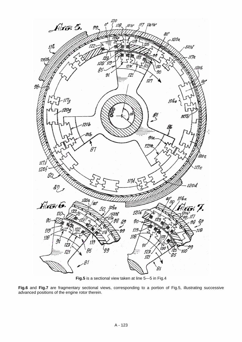
A - 123
Fig.5 is a sectional view taken at line 5---5 in Fig.4
Fig.6 and Fig.7 are fragmentary sectional views, corresponding to a portion of Fig.5, illustrating successive advanced positions of the engine rotor therein.

A - 124
Fig.8 is an exploded perspective view of the rotor and stator of the engine of Fig.3 and Fig.4
Fig.9 is a cross-sectional view taken at line 9---9 of Fig.4
Fig.10 is a partial sectional view, similar to the view of Fig.9, illustrating a different configuration of electromagnets in another engine embodiment of the invention.
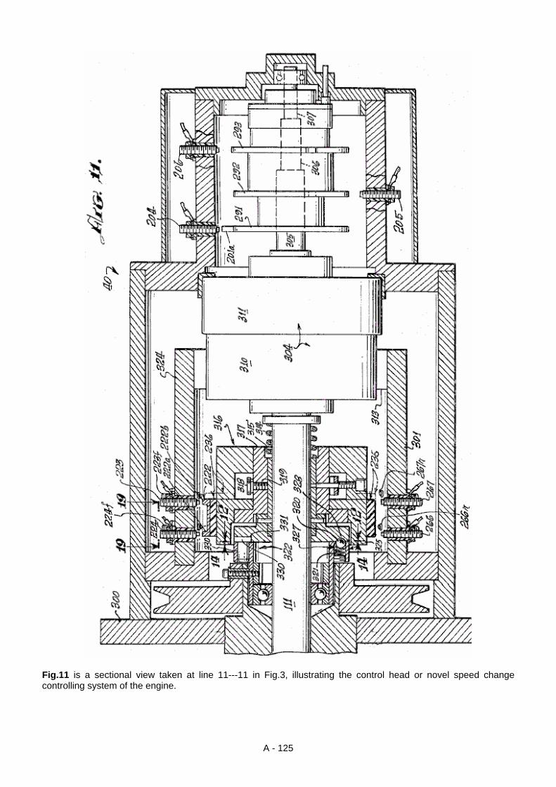
A - 125
Fig.11 is a sectional view taken at line 11---11 in Fig.3, illustrating the control head or novel speed change controlling system of the engine.
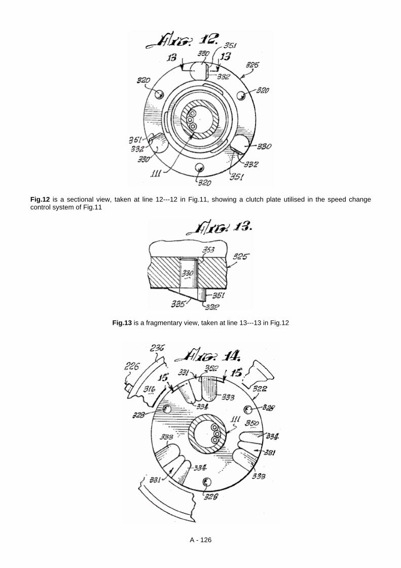
A - 126
Fig.12 is a sectional view, taken at line 12---12 in Fig.11, showing a clutch plate utilised in the speed change control system of Fig.11
Fig.13 is a fragmentary view, taken at line 13---13 in Fig.12
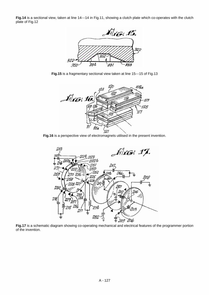
A - 127
Fig.14 is a sectional view, taken at line 14---14 in Fig.11, showing a clutch plate which co-operates with the clutch plate of Fig.12
Fig.15 is a fragmentary sectional view taken at line 15---15 of Fig.13
Fig.16 is a perspective view of electromagnets utilised in the present invention.
Fig.17 is a schematic diagram showing co-operating mechanical and electrical features of the programmer portion of the invention.

A - 128
Fig.18 is an electrical schematic diagram of an engine according to the invention, showing the electrical relationships of the electromagnetic components embodying a new principle of the invention, and
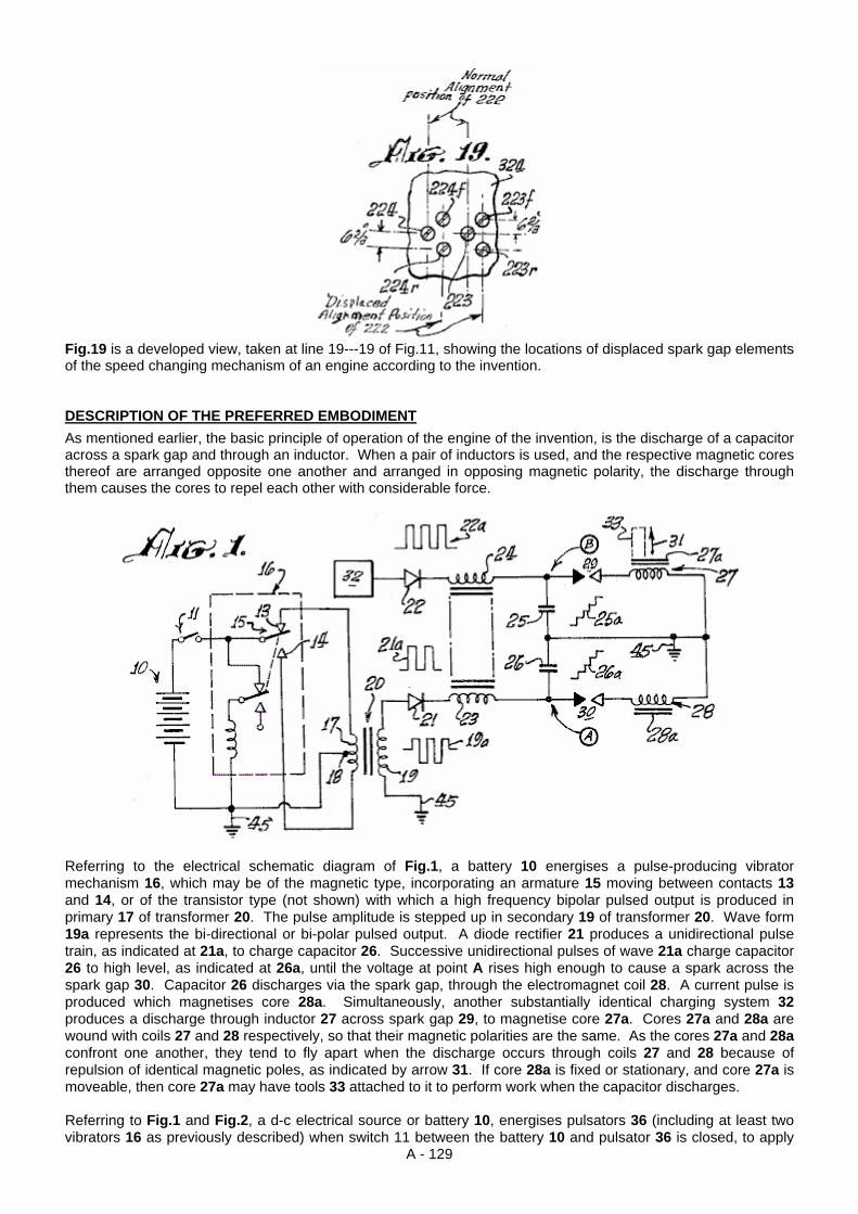
A - 129
Fig.19 is a developed view, taken at line 19---19 of Fig.11, showing the locations of displaced spark gap elements of the speed changing mechanism of an engine according to the invention. DESCRIPTION OF THE PREFERRED EMBODIMENT As mentioned earlier, the basic principle of operation of the engine of the invention, is the discharge of a capacitor across a spark gap and through an inductor. When a pair of inductors is used, and the respective magnetic cores thereof are arranged opposite one another and arranged in opposing magnetic polarity, the discharge through them causes the cores to repel each other with considerable force.
Referring to the electrical schematic diagram of Fig.1, a battery 10 energises a pulse-producing vibrator mechanism 16, which may be of the magnetic type, incorporating an armature 15 moving between contacts 13 and 14, or of the transistor type (not shown) with which a high frequency bipolar pulsed output is produced in primary 17 of transformer 20. The pulse amplitude is stepped up in secondary 19 of transformer 20. Wave form 19a represents the bi-directional or bi-polar pulsed output. A diode rectifier 21 produces a unidirectional pulse train, as indicated at 21a, to charge capacitor 26. Successive unidirectional pulses of wave 21a charge capacitor 26 to high level, as indicated at 26a, until the voltage at point A rises high enough to cause a spark across the spark gap 30. Capacitor 26 discharges via the spark gap, through the electromagnet coil 28. A current pulse is produced which magnetises core 28a. Simultaneously, another substantially identical charging system 32 produces a discharge through inductor 27 across spark gap 29, to magnetise core 27a. Cores 27a and 28a are wound with coils 27 and 28 respectively, so that their magnetic polarities are the same. As the cores 27a and 28a confront one another, they tend to fly apart when the discharge occurs through coils 27 and 28 because of repulsion of identical magnetic poles, as indicated by arrow 31. If core 28a is fixed or stationary, and core 27a is moveable, then core 27a may have tools 33 attached to it to perform work when the capacitor discharges. Referring to Fig.1 and Fig.2, a d-c electrical source or battery 10, energises pulsators 36 (including at least two vibrators 16 as previously described) when switch 11 between the battery 10 and pulsator 36 is closed, to apply
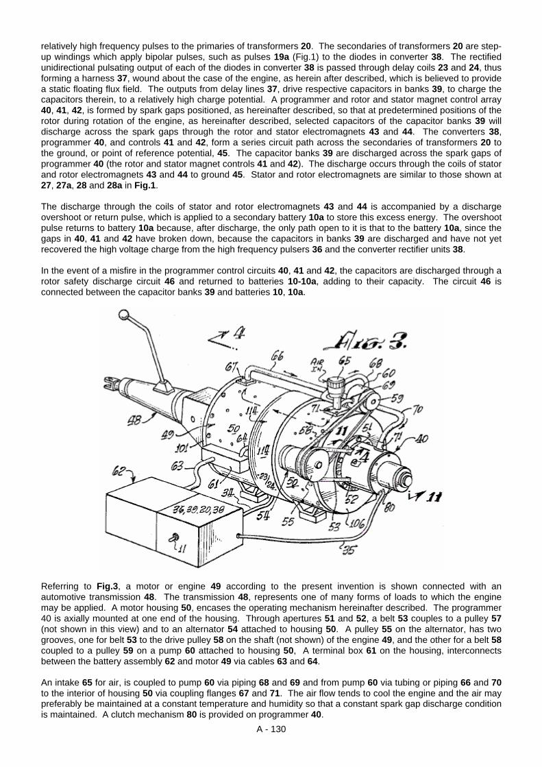
A - 130
relatively high frequency pulses to the primaries of transformers 20. The secondaries of transformers 20 are step-up windings which apply bipolar pulses, such as pulses 19a (Fig.1) to the diodes in converter 38. The rectified unidirectional pulsating output of each of the diodes in converter 38 is passed through delay coils 23 and 24, thus forming a harness 37, wound about the case of the engine, as herein after described, which is believed to provide a static floating flux field. The outputs from delay lines 37, drive respective capacitors in banks 39, to charge the capacitors therein, to a relatively high charge potential. A programmer and rotor and stator magnet control array 40, 41, 42, is formed by spark gaps positioned, as hereinafter described, so that at predetermined positions of the rotor during rotation of the engine, as hereinafter described, selected capacitors of the capacitor banks 39 will discharge across the spark gaps through the rotor and stator electromagnets 43 and 44. The converters 38, programmer 40, and controls 41 and 42, form a series circuit path across the secondaries of transformers 20 to the ground, or point of reference potential, 45. The capacitor banks 39 are discharged across the spark gaps of programmer 40 (the rotor and stator magnet controls 41 and 42). The discharge occurs through the coils of stator and rotor electromagnets 43 and 44 to ground 45. Stator and rotor electromagnets are similar to those shown at 27, 27a, 28 and 28a in Fig.1. The discharge through the coils of stator and rotor electromagnets 43 and 44 is accompanied by a discharge overshoot or return pulse, which is applied to a secondary battery 10a to store this excess energy. The overshoot pulse returns to battery 10a because, after discharge, the only path open to it is that to the battery 10a, since the gaps in 40, 41 and 42 have broken down, because the capacitors in banks 39 are discharged and have not yet recovered the high voltage charge from the high frequency pulsers 36 and the converter rectifier units 38. In the event of a misfire in the programmer control circuits 40, 41 and 42, the capacitors are discharged through a rotor safety discharge circuit 46 and returned to batteries 10-10a, adding to their capacity. The circuit 46 is connected between the capacitor banks 39 and batteries 10, 10a.
Referring to Fig.3, a motor or engine 49 according to the present invention is shown connected with an automotive transmission 48. The transmission 48, represents one of many forms of loads to which the engine may be applied. A motor housing 50, encases the operating mechanism hereinafter described. The programmer 40 is axially mounted at one end of the housing. Through apertures 51 and 52, a belt 53 couples to a pulley 57 (not shown in this view) and to an alternator 54 attached to housing 50. A pulley 55 on the alternator, has two grooves, one for belt 53 to the drive pulley 58 on the shaft (not shown) of the engine 49, and the other for a belt 58 coupled to a pulley 59 on a pump 60 attached to housing 50, A terminal box 61 on the housing, interconnects between the battery assembly 62 and motor 49 via cables 63 and 64. An intake 65 for air, is coupled to pump 60 via piping 68 and 69 and from pump 60 via tubing or piping 66 and 70 to the interior of housing 50 via coupling flanges 67 and 71. The air flow tends to cool the engine and the air may preferably be maintained at a constant temperature and humidity so that a constant spark gap discharge condition is maintained. A clutch mechanism 80 is provided on programmer 40.

A - 131
Referring to Fig.4, Fig.5 and Fig.9, rotor 81 has spider assemblies 83 and 84 with three electromagnet coil assembly sets mounted thereon, two of which are shown in Fig.4, on 85, at 85a and 85b and on 86 at 86a and 86b. One of the third electromagnet coil assemblies, designated 87a, is shown in Fig.5, viewed from the shaft end. As more clearly shown in the perspective view of Fig.8, a third spider assembly 88 provides added rigidity and a central support for the rotor mechanism on shaft 81.
The electromagnet sets 85a, 85b, 86a, 86b, 87a and 87b, disposed on rotor 81 and spiders 83, 84 and 88, each comprise pairs of front units 85a, 86a and 87a and pairs of rear units 85b, 86b and 87b. Each pair consists of a major electromagnet and a minor electromagnet, as hereinafter described, which are imbedded in an insulating
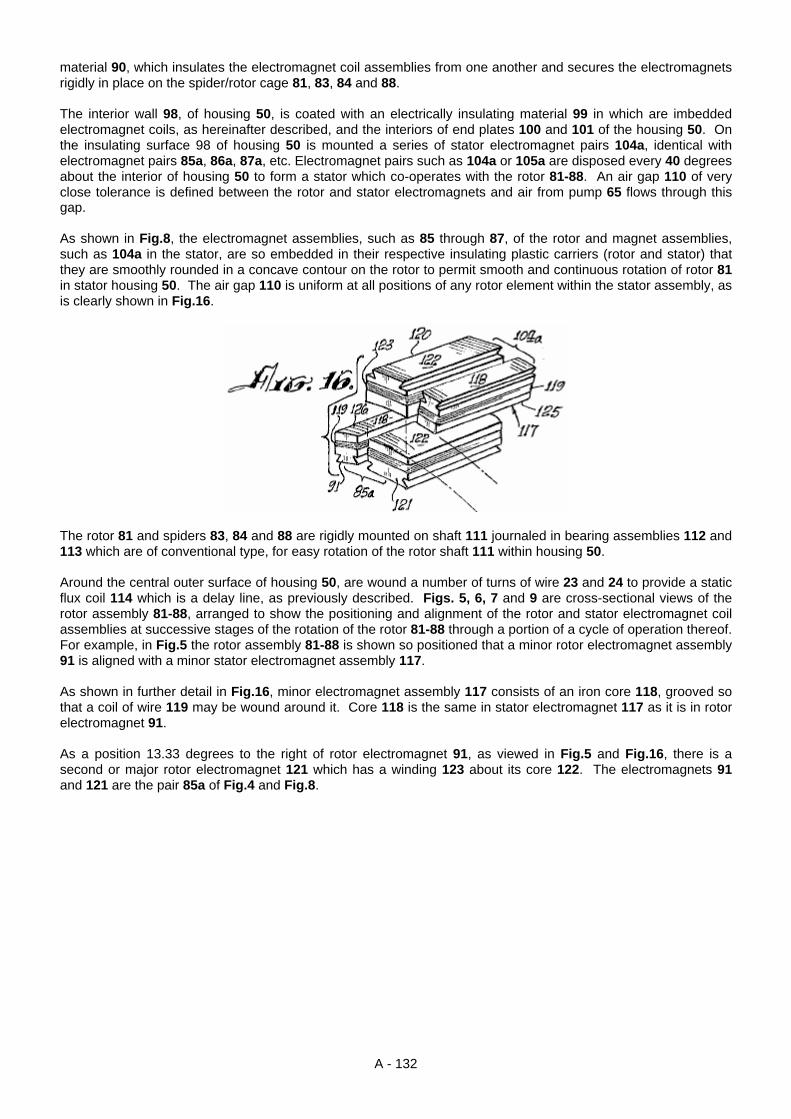
A - 132
material 90, which insulates the electromagnet coil assemblies from one another and secures the electromagnets rigidly in place on the spider/rotor cage 81, 83, 84 and 88. The interior wall 98, of housing 50, is coated with an electrically insulating material 99 in which are imbedded electromagnet coils, as hereinafter described, and the interiors of end plates 100 and 101 of the housing 50. On the insulating surface 98 of housing 50 is mounted a series of stator electromagnet pairs 104a, identical with electromagnet pairs 85a, 86a, 87a, etc. Electromagnet pairs such as 104a or 105a are disposed every 40 degrees about the interior of housing 50 to form a stator which co-operates with the rotor 81-88. An air gap 110 of very close tolerance is defined between the rotor and stator electromagnets and air from pump 65 flows through this gap. As shown in Fig.8, the electromagnet assemblies, such as 85 through 87, of the rotor and magnet assemblies, such as 104a in the stator, are so embedded in their respective insulating plastic carriers (rotor and stator) that they are smoothly rounded in a concave contour on the rotor to permit smooth and continuous rotation of rotor 81 in stator housing 50. The air gap 110 is uniform at all positions of any rotor element within the stator assembly, as is clearly shown in Fig.16.
The rotor 81 and spiders 83, 84 and 88 are rigidly mounted on shaft 111 journaled in bearing assemblies 112 and 113 which are of conventional type, for easy rotation of the rotor shaft 111 within housing 50. Around the central outer surface of housing 50, are wound a number of turns of wire 23 and 24 to provide a static flux coil 114 which is a delay line, as previously described. Figs. 5, 6, 7 and 9 are cross-sectional views of the rotor assembly 81-88, arranged to show the positioning and alignment of the rotor and stator electromagnet coil assemblies at successive stages of the rotation of the rotor 81-88 through a portion of a cycle of operation thereof. For example, in Fig.5 the rotor assembly 81-88 is shown so positioned that a minor rotor electromagnet assembly 91 is aligned with a minor stator electromagnet assembly 117. As shown in further detail in Fig.16, minor electromagnet assembly 117 consists of an iron core 118, grooved so that a coil of wire 119 may be wound around it. Core 118 is the same in stator electromagnet 117 as it is in rotor electromagnet 91. As a position 13.33 degrees to the right of rotor electromagnet 91, as viewed in Fig.5 and Fig.16, there is a second or major rotor electromagnet 121 which has a winding 123 about its core 122. The electromagnets 91 and 121 are the pair 85a of Fig.4 and Fig.8.

A - 133
At a position 13.33 degrees to the left of stator electromagnet 117, as viewed in Fig.5, there is a second or major stator electromagnet 120 whose core 122 is of the same configuration as core 122 of rotor electromagnet 121. A winding 123 about core 122 of electromagnet 120 is of the same character as winding 123 on electromagnet 121. Electromagnet assembly pair 85a on the rotor is identical in configuration to that of the electromagnet stator assembly pair 104a except for the position reversal of the elements 117-120 and 91-121 of the respective pairs. There are none pairs of electromagnets 120-117 (104a) located at 40 degree intervals about the interior of housing 50. The centreline of core 122 of electromagnet 120 is positioned 13.33 degrees to the left of the centreline of the core 118 of electromagnet 117. Three pairs of electromagnets 85a, 86a and 87a are provided on rotor assembly 81-88 as shown in Fig.5. Other combinations are possible, but the number of electromagnets in the rotor should always be in integral fraction of the number of electromagnets in the stator. As shown in Fig.8, for the rotor assembly 85a and 85b, there are three of each of the front and back pairs of electromagnetic assemblies. Similarly, as shown in Fig.4 and Fig.8, there are nine front and back pairs of electromagnets in the stator such as 104a and 104b. In order to best understand the operation of the rotor 81-88 rotating within the stator housing 50 of an engine according to this invention, the positions of rotor electromagnets 91 and stator electromagnets 117 are initially exactly in line at the 13.33 degree peripheral starting position marked on the vertical centreline of Fig.5. The winding direction of the coils of these magnets is such that a d-c current through the coils 119 will produce a particular identical magnet polarity on each of the juxtaposed surfaces 125 of magnet 117 and 126 of magnet 91 (Fig.5). Fig.16 and Fig.6 illustrate the next step in the motion wherein the two major electromagnets, 120 in the stator and 121 in the rotor, are in alignment. When the d-c discharges from the appropriate capacitors in banks 39 occur simultaneously across spark gaps through the coils 119 of electromagnets 117 and 91, at the instant of their alignment, their cores 118, will repel one another to cause rotor assembly 81-88 to rotate clockwise in the direction indicated by arrow 127. The system does not move in the reverse direction because it has been started in the clockwise direction by the alternator motor 54 shown in Fig.3, or by some other starter means. If started counterclockwise, the motor will continue to rotate counterclockwise. As noted earlier, the discharge of any capacitor occurs over a very short interval via its associated spark gap and the resulting magnetic repulsion action imparts motion to the rotor. The discharge event occurs when electromagnets 117 and 91 are in alignment. As shown in Fig.5, rotor electromagnet 91a is aligned with stator electromagnet 117c, and rotor electromagnet 91b is aligned with stator electromagnet 117e at the same time that similar electromagnets 117 and 91 are aligned. A discharge occurs through all six of these electromagnets simultaneously (that is, 117, 91, 117c, 91a, 117e and 91b). A capacitor and a spark gap are required for each coil of each electromagnet. Where, as in the assembly shown in Fig.8, front and back pairs are used, both the axial in-line front and back coils are energised simultaneously by the discharge from a single capacitor or from a bank of paralleled capacitors such as 25 and 26 (Fig.1). Although Fig.4 and Fig.8 indicate the use of front and back electromagnets, it should be evident that only a single electromagnet in any stator position and a corresponding single electromagnet in the rotor position, may be utilised to accomplish the repulsion action of the rotor with respect to the stator. As stated, each electromagnet requires a discharge from a single capacitor or

A - 134
capacitor bank across a spark gap for it to be energised, and the magnetic polarity of the juxtaposed magnetic core faces must be the same, in order to effect the repulsive action required to produce the rotary motion. Referring to Fig.5 and Fig.6, the repulsion action causes the rotor to move 13.33 degrees clockwise, while electromagnets 91, 91a and 91b move away from electromagnets 117, 117c and 117e to bring electromagnets 121, 121a and 121b into respective alignment with electromagnets 120a, 120d and 120f. At this time, a capacitor discharge across a spark-gap into their coils 123 occurs, thus moving the rotor. Another 13.33 degrees ahead, as shown in Fig.7, major electromagnets 121, 121a and 121b come into alignment with minor electromagnets 117a, 117d and 117f, at which time a discharge occurs to repeat the repulsion action, this action continuing as long as d-c power is applied to the system to charge the capacitor banks. Fig.18 further illustrates the sequencing of the capacitor discharges across appropriate spark gap terminal pairs. Nine single stator coils and three single rotor coils are shown with their respective interconnections with the spark gaps and capacitors with which they are associated for discharge. When the appropriate spark gap terminals are aligned, at the points in the positioning of the rotor assembly for most effective repulsion action of juxtaposed electromagnet cores, the discharge of the appropriate charged capacitors across the associated spark gap occurs through the respective coils. The capacitors are discharged is sets of three, through sets of three coils at each discharge position, as the rotor moves through the rotor positions. In Fig.18, the rotor electromagnets are positioned linearly, rather than on a circular base, to show the electrical action of an electric engine according to the invention. These motor electromagnets 201, 202 and 203 are aligned with stator electromagnets 213, 214 and 215 at 0 degrees, 120 degrees and 240 degrees respectively. The stator electromagnets are correspondingly shown in a linear schematic as if rolled out of the stator assembly and laid side by side. For clarity of description, the capacitors associated with the rotor operation 207, 208, 209 and 246, 247, 248, 249, 282 and 283, are arranged in vertical alignment with the respective positions of the rotor coils 201, 202 and 203 as they move from left to right, this corresponding to clockwise rotation of the rotor. The stator coils 213, 214, 215, 260, 261, 262, 263, 264, 265, 266, etc. and capacitor combinations are arranged side by side, again to facilitate description. An insulative disc 236 (shown in Fig.17 as a disc but opened out linearly in Fig.18) has mounted thereon, three gap terminal blocks 222, 225 and 228. Each block is rectangularly U-shaped, and each interconnects two terminals with the base of the U. Block 222 has terminals 222a and 222b. Block 225 has terminals 225a and 225b. Block 228 has terminals 228c and 228d. When insulative disc 230 is part of the rotor as indicated by mechanical linkage 290, it can be seen that terminal U 222 creates a pair of gaps with gap terminals 223 and 224 respectively. Thus, when the voltage on capacitor 216 from charging unit 219, is of a value which will arc over the air spaces between 222a and 223, and between 222b and 224, the capacitor 216 will discharge through the coil of electromagnet 213 to ground. Similarly, gap terminal U 225 forms a dual spark gap with gap terminals 226 and 227 to result in arc-over when the voltage on capacitor 217, charged by charging circuit 220, discharges into the coil of electromagnet 214. Also, U-gap terminal 228 with terminals 228c and 228d, creates a spark gap with terminals 229 and 230 to discharge capacitor 218, charged by charging circuit 221, into coil 215. At the same time, rotor coils, 201, 202 and 203 across gaps 201a - 204, 202b - 205 and 203c - 206 each receives a discharge from respective capacitors 207, 208 and 209. When the electromagnet coils 213, 214 and 215 and 201, 202 and 203 are energised, the repulsion action causes the rotor assembly to move to position 2 where a new simultaneous group of discharges occurs into rotor coils 201, 202 and 203 from capacitors 246, 248 and 282 across gaps 201a - 240, 202b - 242 and 203c - 244. Simultaneously, because gap-U-elements 222, 225 and 228 have also moved to position 2 with the rotor assembly, capacitor 261 is discharged through electromagnet coil 260, capacitor 265 is discharged through electromagnet coil 264, and capacitor 269 is discharged through electromagnet coil 268 in alignment with position 2 of the rotor electromagnet coils, thus to cause the rotor electromagnets to move to position 3 where the discharge pattern is repeated now with capacitors 247, 249 and 283 discharging through the rotor electromagnet coils 201, 202 and 203, and the capacitors 263, 267 and 281 discharging respectively through stator electromagnet coils 262, 266 and 280. After each discharge, the charging circuits 219 - 221 and 272 - 277 for the stator capacitors, and 210 - 212 and 284 - 289 for the rotor capacitors, are operated continuously from a battery source as described earlier with reference to Fig.1, to constantly recharge the capacitors to which each is connected. Those versed in the art will appreciate that, as each capacitor discharges across an associated spark gap, the resulting drop in potential across the gap renders the gap an open circuit until such time as the capacitor can recharge to the arc-over level for the gap. This recharge occurs before a rotor element arrives at the next position in the rotation. The mechanical schematic diagram of Fig.17, further clarifies the operation of the spark-gap discharge programming system. A forward disc 236 of an electrically insulative material, has thereon the set of U-shaped gap terminal connectors previously described. These are positioned at 0 degrees, 120 degrees and 240 degrees respectively. In Fig.17, schematic representations of the position of the coil and capacitor arrangements at the
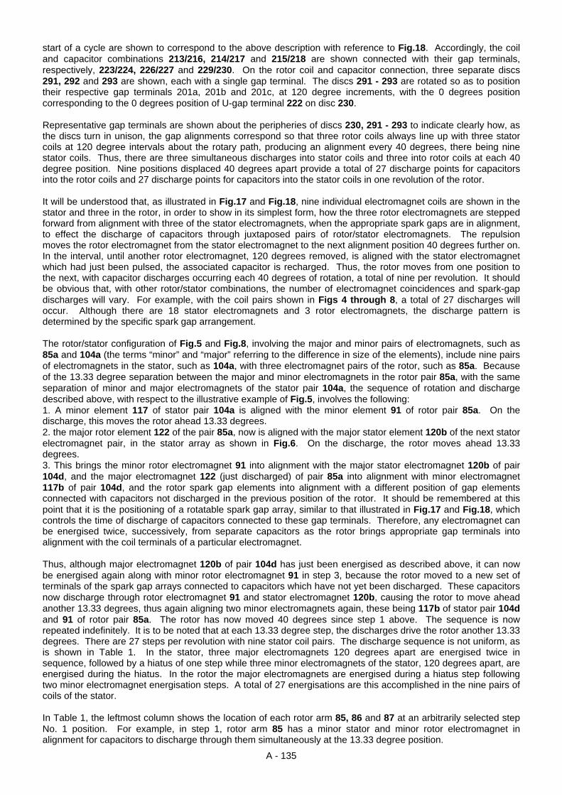
A - 135
start of a cycle are shown to correspond to the above description with reference to Fig.18. Accordingly, the coil and capacitor combinations 213/216, 214/217 and 215/218 are shown connected with their gap terminals, respectively, 223/224, 226/227 and 229/230. On the rotor coil and capacitor connection, three separate discs 291, 292 and 293 are shown, each with a single gap terminal. The discs 291 - 293 are rotated so as to position their respective gap terminals 201a, 201b and 201c, at 120 degree increments, with the 0 degrees position corresponding to the 0 degrees position of U-gap terminal 222 on disc 230. Representative gap terminals are shown about the peripheries of discs 230, 291 - 293 to indicate clearly how, as the discs turn in unison, the gap alignments correspond so that three rotor coils always line up with three stator coils at 120 degree intervals about the rotary path, producing an alignment every 40 degrees, there being nine stator coils. Thus, there are three simultaneous discharges into stator coils and three into rotor coils at each 40 degree position. Nine positions displaced 40 degrees apart provide a total of 27 discharge points for capacitors into the rotor coils and 27 discharge points for capacitors into the stator coils in one revolution of the rotor. It will be understood that, as illustrated in Fig.17 and Fig.18, nine individual electromagnet coils are shown in the stator and three in the rotor, in order to show in its simplest form, how the three rotor electromagnets are stepped forward from alignment with three of the stator electromagnets, when the appropriate spark gaps are in alignment, to effect the discharge of capacitors through juxtaposed pairs of rotor/stator electromagnets. The repulsion moves the rotor electromagnet from the stator electromagnet to the next alignment position 40 degrees further on. In the interval, until another rotor electromagnet, 120 degrees removed, is aligned with the stator electromagnet which had just been pulsed, the associated capacitor is recharged. Thus, the rotor moves from one position to the next, with capacitor discharges occurring each 40 degrees of rotation, a total of nine per revolution. It should be obvious that, with other rotor/stator combinations, the number of electromagnet coincidences and spark-gap discharges will vary. For example, with the coil pairs shown in Figs 4 through 8, a total of 27 discharges will occur. Although there are 18 stator electromagnets and 3 rotor electromagnets, the discharge pattern is determined by the specific spark gap arrangement. The rotor/stator configuration of Fig.5 and Fig.8, involving the major and minor pairs of electromagnets, such as 85a and 104a (the terms “minor” and “major” referring to the difference in size of the elements), include nine pairs of electromagnets in the stator, such as 104a, with three electromagnet pairs of the rotor, such as 85a. Because of the 13.33 degree separation between the major and minor electromagnets in the rotor pair 85a, with the same separation of minor and major electromagnets of the stator pair 104a, the sequence of rotation and discharge described above, with respect to the illustrative example of Fig.5, involves the following: 1. A minor element 117 of stator pair 104a is aligned with the minor element 91 of rotor pair 85a. On the discharge, this moves the rotor ahead 13.33 degrees. 2. the major rotor element 122 of the pair 85a, now is aligned with the major stator element 120b of the next stator electromagnet pair, in the stator array as shown in Fig.6. On the discharge, the rotor moves ahead 13.33 degrees. 3. This brings the minor rotor electromagnet 91 into alignment with the major stator electromagnet 120b of pair 104d, and the major electromagnet 122 (just discharged) of pair 85a into alignment with minor electromagnet 117b of pair 104d, and the rotor spark gap elements into alignment with a different position of gap elements connected with capacitors not discharged in the previous position of the rotor. It should be remembered at this point that it is the positioning of a rotatable spark gap array, similar to that illustrated in Fig.17 and Fig.18, which controls the time of discharge of capacitors connected to these gap terminals. Therefore, any electromagnet can be energised twice, successively, from separate capacitors as the rotor brings appropriate gap terminals into alignment with the coil terminals of a particular electromagnet. Thus, although major electromagnet 120b of pair 104d has just been energised as described above, it can now be energised again along with minor rotor electromagnet 91 in step 3, because the rotor moved to a new set of terminals of the spark gap arrays connected to capacitors which have not yet been discharged. These capacitors now discharge through rotor electromagnet 91 and stator electromagnet 120b, causing the rotor to move ahead another 13.33 degrees, thus again aligning two minor electromagnets again, these being 117b of stator pair 104d and 91 of rotor pair 85a. The rotor has now moved 40 degrees since step 1 above. The sequence is now repeated indefinitely. It is to be noted that at each 13.33 degree step, the discharges drive the rotor another 13.33 degrees. There are 27 steps per revolution with nine stator coil pairs. The discharge sequence is not uniform, as is shown in Table 1. In the stator, three major electromagnets 120 degrees apart are energised twice in sequence, followed by a hiatus of one step while three minor electromagnets of the stator, 120 degrees apart, are energised during the hiatus. In the rotor the major electromagnets are energised during a hiatus step following two minor electromagnet energisation steps. A total of 27 energisations are this accomplished in the nine pairs of coils of the stator. In Table 1, the leftmost column shows the location of each rotor arm 85, 86 and 87 at an arbitrarily selected step No. 1 position. For example, in step 1, rotor arm 85 has a minor stator and minor rotor electromagnet in alignment for capacitors to discharge through them simultaneously at the 13.33 degree position.
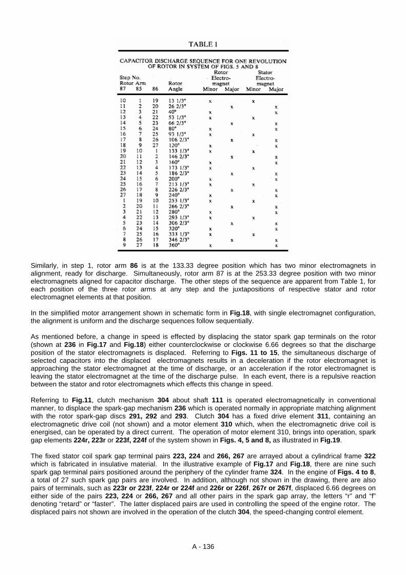
A - 136
Similarly, in step 1, rotor arm 86 is at the 133.33 degree position which has two minor electromagnets in alignment, ready for discharge. Simultaneously, rotor arm 87 is at the 253.33 degree position with two minor electromagnets aligned for capacitor discharge. The other steps of the sequence are apparent from Table 1, for each position of the three rotor arms at any step and the juxtapositions of respective stator and rotor electromagnet elements at that position. In the simplified motor arrangement shown in schematic form in Fig.18, with single electromagnet configuration, the alignment is uniform and the discharge sequences follow sequentially. As mentioned before, a change in speed is effected by displacing the stator spark gap terminals on the rotor (shown at 236 in Fig.17 and Fig.18) either counterclockwise or clockwise 6.66 degrees so that the discharge position of the stator electromagnets is displaced. Referring to Figs. 11 to 15, the simultaneous discharge of selected capacitors into the displaced electromagnets results in a deceleration if the rotor electromagnet is approaching the stator electromagnet at the time of discharge, or an acceleration if the rotor electromagnet is leaving the stator electromagnet at the time of the discharge pulse. In each event, there is a repulsive reaction between the stator and rotor electromagnets which effects this change in speed. Referring to Fig.11, clutch mechanism 304 about shaft 111 is operated electromagnetically in conventional manner, to displace the spark-gap mechanism 236 which is operated normally in appropriate matching alignment with the rotor spark-gap discs 291, 292 and 293. Clutch 304 has a fixed drive element 311, containing an electromagnetic drive coil (not shown) and a motor element 310 which, when the electromagnetic drive coil is energised, can be operated by a direct current. The operation of motor element 310, brings into operation, spark gap elements 224r, 223r or 223f, 224f of the system shown in Figs. 4, 5 and 8, as illustrated in Fig.19. The fixed stator coil spark gap terminal pairs 223, 224 and 266, 267 are arrayed about a cylindrical frame 322 which is fabricated in insulative material. In the illustrative example of Fig.17 and Fig.18, there are nine such spark gap terminal pairs positioned around the periphery of the cylinder frame 324. In the engine of Figs. 4 to 8, a total of 27 such spark gap pairs are involved. In addition, although not shown in the drawing, there are also pairs of terminals, such as 223r or 223f, 224r or 224f and 226r or 226f, 267r or 267f, displaced 6.66 degrees on either side of the pairs 223, 224 or 266, 267 and all other pairs in the spark gap array, the letters “r” and “f” denoting “retard” or “faster”. The latter displaced pairs are used in controlling the speed of the engine rotor. The displaced pairs not shown are involved in the operation of the clutch 304, the speed-changing control element.

A - 137
Clutch 304 is associated with shaft 111 in that the movable element 310 draws clutch disc element 316 on shaft 111, away from clutch disc element 322 when energised by a voltage of appropriate polarity applied to its motor electromagnet 311. Such clutch drives are well known in the art. The clutch mechanism 304 of Fig.11 and Fig.19, when not energised, is in the configuration shown in Fig.11. The energised configuration of clutch 304 is not specifically illustrated. Upon energisation, spark-gap element 222 on disc 236 is displaced rightward, as viewed in Fig.11, by broken lines 236X, into alignment with the positions of fixed spark-gap terminals 223f, 224f and 267r, 266r. When the disc is in position 236X, the flattened edge 332 of pin 330 in disc 325 rides on surface 350 of disc 322. Normally, the flattened edges 351 of pins 330 are engaged against the flat edge 352 in recess 331 of disc 322. The displacement of disc 322 on shaft 111 is effected by the action of clutch 304 against spring 314 (Fig.11). An electric switch (not shown) of clutch mechanism 304 energises it from a d-c power source, and has two positions, one for deceleration and one for acceleration. In either position, clutch 304 is engaged to pull clutch disc 322 from clutch disc 325, momentarily. For the decelerate or the accelerate position, the displaced alignment of spark gap elements 222 is with the 224f, 223f and the 224r, 223r spark-gap terminal elements. However, only the 224f, 223f spark-gap elements are switched into operation with appropriate capacitors for the accelerate position, while in the decelerate position, only the 223r and 224r spark-gap elements are switched into the circuit with their associated capacitors. Of course, when insulative disc 236 is displaced by clutch 304, its gap terminals 222, 225 and 228 (Fig.14 and Fig.18) are all displaced into the alignment position of 236X so as to engage the “r” and “f” lines of fixed spark gap elements. Although the accelerate and decelerate positions of disc 236 are the same, it is the switching into operation of the 223, 224 or 266, 267 exemplary “r” or “f” pairs of terminals which determines whether the rotor will speed up or slow down. The momentary displacement of clutch disc 322 from clutch disc 325 results in rotation of disc 325 about disc 322 through an angle of 120 degrees. The detent ball and spring mechanism 320, 321 in disc 325, positions itself between one detent dimple 328 and a succeeding one 328 at a position 120 degrees away on disc 325. As stated, flat 332 of pin 330 rides on surface 350 of disc 322, and pin 330 leaves the pin-holding groove 331/352 along ramp 333 in disc 322 during the momentary lifting of disc 322 by clutch 304. Pin 330 falls back into the next groove 331 at a point 120 degrees further on about disc 322. Pin 330 falls into place in groove 331 on ramp 334. Pins 330 are rotatable in their sockets 353, so that for either clockwise or counterclockwise rotation, the flat 351 will engage the flat 352 by the particular ramp it encounters. The deceleration or acceleration due to the action of clutch 304 thus occurs within a 120 degree interval of rotation of disc 325. During this interval, disc 322 may only move a fraction of this arc. There has been described earlier, an electromotive engine system wherein at least one electromagnet is in a fixed position and a second electromagnet of similar configuration is juxtaposed with it in a magnetic polarity relationship such that, when the cores of the electromagnets are energised, the juxtaposed core faces repel each other. One core being fixed, and the second core being free to move, any attachments to the second electromagnet core will move with it. Hence, if a plurality of fixed cores are positioned about a circular confining housing, and, within the housing, cores on a shaft are free to move, the shaft is urged rotationally each time the juxtaposed fixed and rotatable cores are in alignment and energised. Both the fixed and the movable cores are connected to spark gap terminal elements and the associated other terminal elements of the spark gaps are connected to capacitors which are charged to high voltage from pulsed unipolar signal generators. These capacitors are discharged through the electromagnets across the spark gaps. By switching selected groups of capacitors into selected pairs of spark gap elements for discharge through the electromagnets, the rotor of the circular array systems is accelerated and decelerated. By confining a fixed electromagnet array in a linear configuration, with a linearly movable electromagnet to which a working tool is attached, exciting the juxtaposed pairs of electromagnets by capacitor discharge, results in the generation of linear force for such tools as punch presses, or for discharging projectiles with considerable energy. CLAIMS: 1. An electric engine comprising: A housing; An array of electromagnets uniformly spaced in said housing to form a stator;

A - 138
A rotor cage on a shaft journaled in and rotatable within said stator, said rotor cage having thereon a spaced array of electromagnets similar to said stator electromagnets and in number, comprising an integral fraction of the number of electromagnets in said stator array; Each of the electromagnets of said stator and of said rotor, having a core which can be magnetised and of a particular configuration and each being wound with a coil such that a pulses of unidirectional electric current through said coil, magnetises the respective core thereof to a particular magnetic polarity, and the faces of rotor cores juxtaposing selected stator cores are magnetised to the same polarity, the juxtaposed cores thereby tending to repel one another, one lead of each of the stator and rotor coils being connected to a common terminal, the other lead of each of said coils being connected to a gap terminal, the gap terminals of said rotor coils being on the rotor and equal in number to the number of coils thereon and matching the positions of said rotor electromagnets thereon, the gap terminals of said stator being equal in number to the number of coils on the stator and disposed uniformly about said stator to match the positions of said stator electromagnets within said housing; A first array of capacitors, each having a terminal in common with the common coil terminal of said stator electromagnets, and each capacitor having its other terminal connected to a gap terminal arrayed adjacent the gap terminal of an electromagnet associated therewith; A second array of capacitors, each having a terminal in common with said common terminal of said rotor electromagnet coils but equal in number to the number of capacitors in said stator array, the other terminals of said capacitors in said second array being connected to gap terminals arrayed about said housing so as to be in axial alignment with said stator gap terminal positions and being alignable with said rotor gap terminals as said rotor is rotated in said housing and respective gap terminals of said rotor coils pass each second array capacitor gap terminals at a predetermined gap distance; Gap coupling terminals on said rotor equal in number to the number of rotor electromagnet coils and positioned to match the rotor electromagnet positions on said rotor, the gap coupling terminals being rotatable with said rotor so as to pass said adjacent stator coil and associated stator capacitor gap terminal at a predetermined distance therefrom; A plurality of capacitor charging circuits connected respectively across each of said capacitors in both said first and said second arrays of capacitors for charging each of said capacitors to a predetermined high d-c potential; A first source of unidirectional electric potential connected to each of said capacitor charging circuits for energising said charging circuits; and A second unidirectional electric potential source connected to said electromagnets of said rotor and said stator of such polarity as to receive a charge from the inverse inductive discharge of the electromagnet coils as their fields collapse following the discharge of each capacitor through a rotor or stator electromagnet coil, Whereby, whenever a rotor electromagnet is aligned opposite a stator electromagnet, the rotor coil gap terminal of that electromagnet is opposite an associated second capacitor array gap terminal, and a gap coupling terminal of said rotor is aligned opposite the stator electromagnet coil gap terminal and associated first capacitor gap terminal, the capacitors discharge the charge thereon across the gaps through their associated electromagnet coils to magnetise their respective juxtaposed electromagnet cores to cause them to repel one another, thus aligning a succeeding pair of rotor and stator electromagnets for capacitor discharge across their respective gaps, to cause them to repel one another, alignments rotor rotation within the housing continuously bringing successive rotor-stator electromagnets into alignment for discharge of the capacitors through them to produce continuous rotary motion of the rotor on said rotor shaft, so long as energy is applied to said charging circuits to recharge said capacitors after each discharge. 2. In an electric engine having a rotor comprising electromagnetic coil means roatatable within a stator comprising similar electromagnetic coil means, said electromagnetic coil means being polarised for magnetic repulsion; Capacitor means electrically coupled across successive spark gaps to selected ones of said stator and all of the coils of said rotor; Charging means connected to said capacitor means for charging said capacitor means to an electrical charge potential sufficient to cause arcing across said spark gaps to result in the discharge of said capacitor means through the electromagnetic coil means repel one another; and A unidirectional electric power source connected to said charging means to energise said charging means to continue charging said capacitor means following each discharge whereby the rotor of said engine is maintained

A - 139
in rotation by the successive discharges of said capacitor means across successive spark gaps into said electromagnetic coil means. 3. An electric engine according to claim 2, wherein: The charging means includes electronic square core oscillators connected to said unidirectional electric power source and includes step-up means and a rectifier to produce a substantial voltage step up from the voltage of said power source. 4. An electric engine according to claim 2, wherein: The charging means includes a vibrator connected to said power source, and step-up transformer and rectifier means to provide a high voltage for charging said capacitor means. 5. A motive force-producing means comprising: At least a first electromagnet means including at least one coil wound about a core, At least a second electromagnet means including at least one coil wound about a core similar to said first core, The respective cores being positioned adjacent to one another so that the magnetic polarities of the adjacent core surfaces are the same when a unidirectional electric current is passed through the coils, At least one capacitor means having one terminal thereof connected to one terminal of both of said electromagnet coils, The other terminal of said capacitor means being connected to one terminal of a spark gap means, the other terminals of the coils of both said first and said second electromagnet means being connected to the other terminal of said spark gap means, At least one unidirectional pulse charging means connected to said capacitor means to charge said capacitor means to a relatively high potential sufficient to arc across said spark gap means at predetermined spacing of said gap terminals, and A source of unidirectional potential connected to said charging circuit to energise said charging means, Whereby upon application of current from said potential source to said charging means the successive pulses generated thereby charge said capacitor means to a voltage level sufficient to arc across said spark gap means to produce a discharge path for said capacitor means through said coils to cause said electromagnet means to repel one another with a substantial force. 6. A motive force-producing means according to claim 5, wherein: Said first electromagnet means is secured in a relatively stable housing, and said second electromagnet means is connected with and freely movable relative to said stable housing, and has utilisation means connected thereto for performing work therewith when said capacitor means discharges through said coils of said electromagnet means. 7. A motive force-producing means according to claim 6, wherein said utilisation means is a motor rotor coupled with said second electromagnet means and said first electromagnet means is a stator. 8. A motive force-producing means according to claim 6, wherein said utilisation means is a piston attached to said second electromagnet means and is movable therewith to produce hammer-like blows when said capacitor means discharges through said electromagnet means. 9. In an electromotive force-generating system as disclosed, means for accelerating or decelerating the motion of a force-generating system, said means comprising: At least two juxtaposed electromagnetic core elements, one fixed and one movable, including coils wound around it to provide a repulsion tendency when said cores are energised, Spark gap terminals connected with said coils,

A - 140
Capacitor means connected with said spark gap terminals to discharge across said spark gap terminals through said coils when a charge of sufficient voltage level appears across said capacitor means, thus to energise said juxtaposed electromagnets to induce said juxtaposed electromagnet cores to repel one another, Charging means connected to said capacitors for charging them to said sufficient voltage level, and selective positioning means coupled with said spark gap terminals and with at least said movable electromagnet core to cause selective displacement of said movable core with respect to said fixed core. 10. An electromotive force-generating system according to claim 9, wherein: Said juxtaposed electromagnetic cores include a plurality of fixed cores and a smaller number of movable cores, said smaller number being an integral fraction of the number of fixed cores, and Said selective positioning means is an electromagnetic clutch coupled with said smaller number of movable cores for movement therewith, and includes selective displacement means coupled with said spark gap terminals connected with said capacitors in said capacitor means and selected combinations of coils in said plurality of fixed electromagnets. 11. The method of generating motive power comprising the steps of: a. positioning similar electromagnets in juxtaposed relationship with their respective cores arranged for repulsion when said electromagnets are energised, b. charging capacitors to a relatively high potential, and c. discharging said capacitors simultaneously through said electromagnets across spark gaps set to break down at said relatively high potential, thereby to cause said similar electromagnets to repel one another with considerable force. 12. The method of generating motive power defined in claim 11, wherein, in said positioning step at least one of said electromagnets is maintained in a fixed position and another electromagnet is free to move relative to said fixed electromagnet. 13. The method of generating motive power according to claim 11, wherein: The charging step includes the charging of capacitors to a relatively high potential from a pulsed unipolar source of electrical energy. 14. in an electromagnetic capacitor discharge engine including movable electromagnets and fixed electromagnets, said movable electromagnets being movable into polar alignment with said fixed electromagnets, capacitor means, means for charging said capacitor means, and means for discharging said charged capacitor means through said fixed and movable electromagnets to polarise aligned fixed and movable electromagnets for magnetic repulsion, an acceleration and deceleration control means comprising: First selective means for momentarily delaying the discharge of the capacitors until the movable electromagnets in said engine have begun to recede from the fixed electromagnets, in order to accelerate the motion of said movable electromagnets by the added impetus of the repulsion, and Second selective means for momentarily accelerating the discharge of the capacitors to occur at a point in the motion of the movable electromagnets where said movable electromagnets are approaching said fixed electromagnets to decelerate the motion of said movable electromagnets by the tendency to repel the approaching electromagnets by the fixed electromagnets. 15. An electric engine, comprising: Fixed electromagnets; Movable electromagnets, movable into alignment with said fixed electromagnets; Capacitor means; Means for charging said capacitor means, and

A - 141
Means for discharging said charged capacitor means through said fixed and movable electromagnets to polarise said aligned fixed and movable electromagnets for magnetic repulsion. 16. An electric engine as recited in claim 15, wherein: said means for discharging said charged capacitor means comprises voltage breakdown switch means. 17. An electric engine as recited in claim 16, wherein: Said voltage breakdown switch means includes at least one terminal movable with at least one of said movable electromagnets for breaking down when said at least one of said movable electromagnets is in alignment with a said fixed electromagnet. 18. An electric engine as recited in claim 17, wherein: Said voltage breakdown switch means comprises a spark gap means.

A - 142
EDWIN GRAY: POWER SUPPLY
US Patent 4,595,975 June 17, 1986 Inventor: Edwin V. Gray snr.
EFFICIENT POWER SUPPLY SUITABLE FOR INDUCTIVE LOADS
Please note that this is a re-worded excerpt from this patent. It describes the circuitry used with Edwin Gray’s power tube. Please be aware Edwin wanted at all costs, to conceal any useful technology while getting patents to encourage investors, so please understand that this patent is not intended to tell you how to make a working system of this type.
Fig.1 is a schematic circuit diagram of the electrical driving system. Fig.2 is an elevational sectional view of the electrical conversion element. Fig.3 is a plan sectional view taken along line 3--3 of Fig.2. Fig.4 is a plan sectional view taken along line 4--4 of Fig.2. Fig.5 is a schematic circuit diagram of the alternating-current input circuit. SUMMARY OF THE INVENTION The present invention provides a more efficient driving system comprising a source of electrical voltage; a vibrator connected to the low-voltage source for forming a pulsating signal; a transformer connected to the vibrator for receiving the pulsating signal; a high-voltage source, where available, connected to a bridge-type rectifier; or the bridge-type rectifier connected to the high voltage pulse output of the transformer; a capacitor for receiving the voltage pulse output; a conversion element having first and second anodes, electrically conductive means for receiving a charge positioned about the second anode and an output terminal connected to the charge receiving means, the second anode being connected to the capacitor; a commutator connected to the source of electrical voltage and to the first anode; and an inductive load connected to the output terminal whereby a high energy discharge between the first and second anodes is transferred to the charge receiving means and then to the inductive load. As a sub-combination, the present invention also includes a conversion element comprising a housing; a first low voltage anode mounted to the housing, the first anode adapted to be connected to a voltage source; a second high voltage anode mounted to the housing, the second anode adapted to be connected to a voltage source; electrically conductive means positioned about the second anode and spaced therefrom for receiving a charge, the charge receiving means being mounted to the housing; and an output terminal communicating with the charge receiving means, said terminal adapted to be connected to an inductive load. The invention also includes a method for providing power to an inductive load comprising the steps of providing a voltage source, pulsating a signal from said source; increasing the voltage of said signal; rectifying said signal; storing and increasing the signal; conducting said signal to a high voltage anode; providing a low voltage to a second anode to form a high energy discharge; electrostatically coupling the discharge to a charge receiving element; conducting the discharge to an inductive load; coupling a second capacitor to the load; and coupling the second capacitor to the source. It is an aim of the present invention to provide a system for driving an inductive load which system is substantially more efficient than any now existing. Another object of the present invention is to provide a system for driving an inductive load which is reliable, is inexpensive and simply constructed. The foregoing objects of the present invention together with various other objects, advantages, features and results thereof which will be evident to those skilled in the art in light of this disclosure may be achieved with the exemplary embodiment of the invention described in detail hereinafter and illustrated in the accompanying drawings.

A - 143
DESCRIPTION OF THE PREFERRED EMBODIMENT While the present invention is susceptible of various modifications and alternative constructions, an embodiment is shown in the drawings and will herein be described in detail. It should be understood however that it is not the intention to limit the invention to the particular form disclosed; but on the contrary, the invention is to cover all modifications, equivalents and alternative constructions falling within the spirit and scope of the invention as expressed in the appended claims. There is disclosed herein an electrical driving system which, on theory, will convert low voltage electric energy from a source such as an electric storage battery to a high potential, high current energy pulse that is capable of developing a working force at the inductive output of the device that is more efficient than that which is capable of being developed directly from the energy source. The improvement in efficiency is further enhanced by the capability of the device to return that portion of the initial energy developed, and not used by the inductive load in the production of mechanical energy, to the same or second energy reservoir or source for use elsewhere, or for storage. This system accomplishes the results stated above by harnessing the “electrostatic” or “impulse” energy created by a high-intensity spark generated within a specially constructed electrical conversion switching element tube. This element utilises a low-voltage anode, a high-voltage anode, and one or more “electrostatic” or charge receiving grids. These grids are of a physical size, and appropriately positioned, as to be compatible with the size of the tube, and therefore, directly related to the amount of energy to be anticipated when the device is operating. The low-voltage anode may incorporate a resistive device to aid in controlling the amount of current drawn from the energy source. This low-voltage anode is connected to the energy source through a mechanical commutator or a solid-state pulser that controls the timing and duration of the energy spark within the element. The high-voltage anode is connected to a high- voltage potential developed by the associated circuits. An energy discharge occurs within the element when the external control circuits permit. This short duration, high-voltage, high-current energy pulse is captured by the “electrostatic” grids within the tube, stored momentarily, then transferred to the inductive output load. The increase in efficiency anticipated in converting the electrical energy to mechanical energy within the inductive load is attributed to the utilisation of the most optimum timing in introducing the electrical energy to the load device, for the optimum period of time. Further enhancement of energy conservation is accomplished by capturing a significant portion of the energy generated by the inductive load when the useful energy field is collapsing. This energy is normally dissipated in load losses that are contrary to the desired energy utilisation, and have heretofore been accepted because no suitable means had been developed to harness this energy and restore it to a suitable energy storage device. The present invention is concerned with two concepts or characteristics. The first of these characteristics is observed with the introduction of an energising cur- rent through the inductor. The inductor creates a contrary force (counter-electromotive force or CEMP) that opposes the energy introduced into the inductor. This CEMF increases throughout the time the introduced energy is increasing. In normal applications of an alternating-current to an inductive load for mechanical applications, the useful work of the inductor is accomplished prior to terminating the application of energy. The excess energy applied is thereby wasted. Previous attempts to provide energy inputs to an inductor of time durations limited to that period when the optimum transfer of inductive energy to mechanical energy is occurring, have been limited by the ability of any such device to handle the high current required to optimise the energy transfer. The second characteristic is observed when the energising current is removed from the inductor, As the current is decreased, the inductor generates an EMF that opposes the removal of current or, in other words, produces an energy source at the output of the inductor that simulates the original energy source, reduced by the actual energy removed from the circuit by the mechanical load. This “regenerated”, or excess, energy has previously been lost due to a failure to provide a storage capability for this energy. In this invention, a high-voltage, high-current, short duration energy pulse is applied to the inductive load by the conversion element. This element makes possible the use of certain of that energy impressed within an arc across a spark-gap, without the resultant deterioration of circuit elements normally associated with high energy electrical arcs. This invention also provides for capture of a certain portion of the energy induced by the high inductive kick
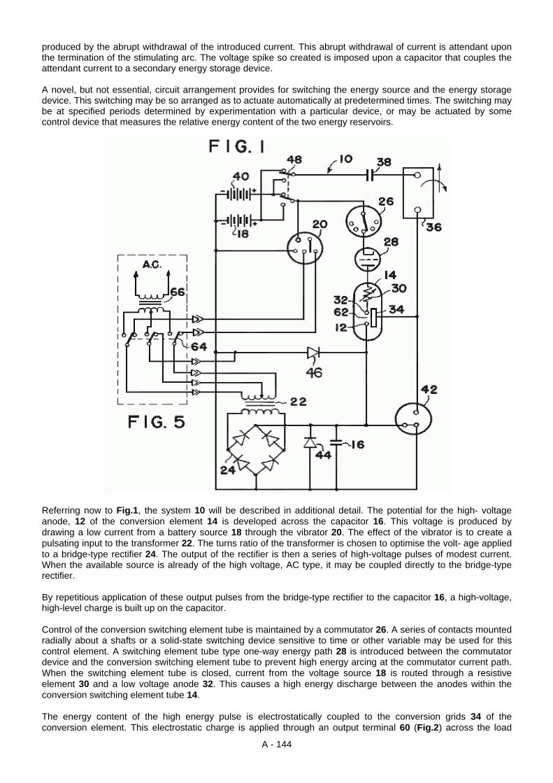
A - 144
produced by the abrupt withdrawal of the introduced current. This abrupt withdrawal of current is attendant upon the termination of the stimulating arc. The voltage spike so created is imposed upon a capacitor that couples the attendant current to a secondary energy storage device. A novel, but not essential, circuit arrangement provides for switching the energy source and the energy storage device. This switching may be so arranged as to actuate automatically at predetermined times. The switching may be at specified periods determined by experimentation with a particular device, or may be actuated by some control device that measures the relative energy content of the two energy reservoirs.
Referring now to Fig.1, the system 10 will be described in additional detail. The potential for the high- voltage anode, 12 of the conversion element 14 is developed across the capacitor 16. This voltage is produced by drawing a low current from a battery source 18 through the vibrator 20. The effect of the vibrator is to create a pulsating input to the transformer 22. The turns ratio of the transformer is chosen to optimise the volt- age applied to a bridge-type rectifier 24. The output of the rectifier is then a series of high-voltage pulses of modest current. When the available source is already of the high voltage, AC type, it may be coupled directly to the bridge-type rectifier. By repetitious application of these output pulses from the bridge-type rectifier to the capacitor 16, a high-voltage, high-level charge is built up on the capacitor. Control of the conversion switching element tube is maintained by a commutator 26. A series of contacts mounted radially about a shafts or a solid-state switching device sensitive to time or other variable may be used for this control element. A switching element tube type one-way energy path 28 is introduced between the commutator device and the conversion switching element tube to prevent high energy arcing at the commutator current path. When the switching element tube is closed, current from the voltage source 18 is routed through a resistive element 30 and a low voltage anode 32. This causes a high energy discharge between the anodes within the conversion switching element tube 14. The energy content of the high energy pulse is electrostatically coupled to the conversion grids 34 of the conversion element. This electrostatic charge is applied through an output terminal 60 (Fig.2) across the load
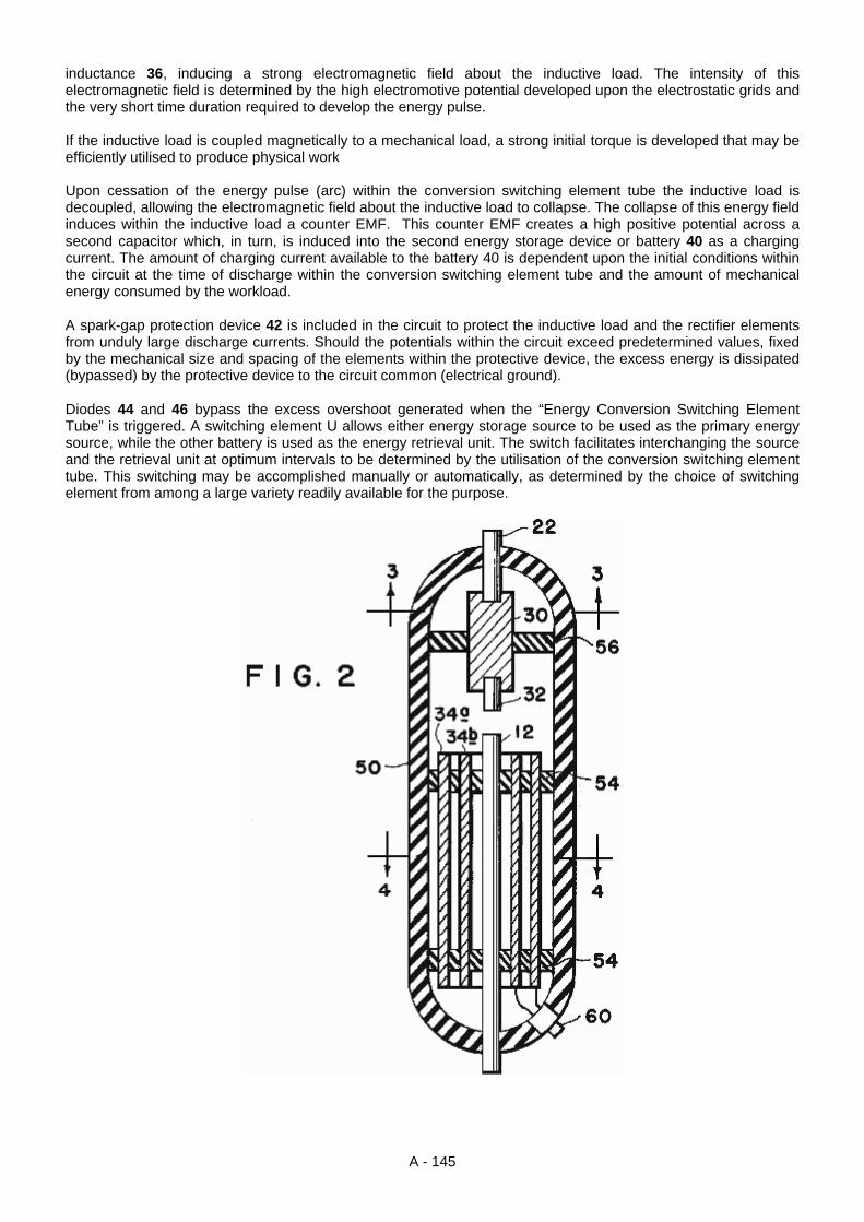
A - 145
inductance 36, inducing a strong electromagnetic field about the inductive load. The intensity of this electromagnetic field is determined by the high electromotive potential developed upon the electrostatic grids and the very short time duration required to develop the energy pulse. If the inductive load is coupled magnetically to a mechanical load, a strong initial torque is developed that may be efficiently utilised to produce physical work Upon cessation of the energy pulse (arc) within the conversion switching element tube the inductive load is decoupled, allowing the electromagnetic field about the inductive load to collapse. The collapse of this energy field induces within the inductive load a counter EMF. This counter EMF creates a high positive potential across a second capacitor which, in turn, is induced into the second energy storage device or battery 40 as a charging current. The amount of charging current available to the battery 40 is dependent upon the initial conditions within the circuit at the time of discharge within the conversion switching element tube and the amount of mechanical energy consumed by the workload. A spark-gap protection device 42 is included in the circuit to protect the inductive load and the rectifier elements from unduly large discharge currents. Should the potentials within the circuit exceed predetermined values, fixed by the mechanical size and spacing of the elements within the protective device, the excess energy is dissipated (bypassed) by the protective device to the circuit common (electrical ground). Diodes 44 and 46 bypass the excess overshoot generated when the “Energy Conversion Switching Element Tube” is triggered. A switching element U allows either energy storage source to be used as the primary energy source, while the other battery is used as the energy retrieval unit. The switch facilitates interchanging the source and the retrieval unit at optimum intervals to be determined by the utilisation of the conversion switching element tube. This switching may be accomplished manually or automatically, as determined by the choice of switching element from among a large variety readily available for the purpose.
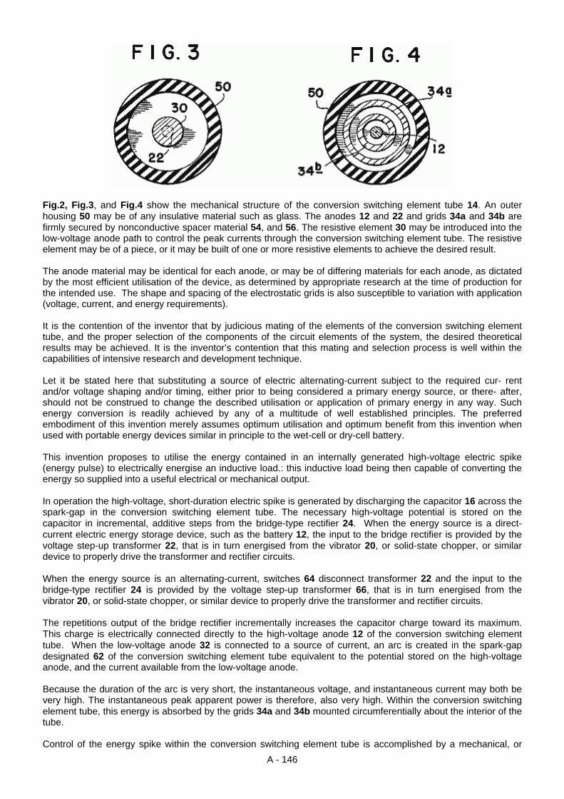
A - 146
Fig.2, Fig.3, and Fig.4 show the mechanical structure of the conversion switching element tube 14. An outer housing 50 may be of any insulative material such as glass. The anodes 12 and 22 and grids 34a and 34b are firmly secured by nonconductive spacer material 54, and 56. The resistive element 30 may be introduced into the low-voltage anode path to control the peak currents through the conversion switching element tube. The resistive element may be of a piece, or it may be built of one or more resistive elements to achieve the desired result. The anode material may be identical for each anode, or may be of differing materials for each anode, as dictated by the most efficient utilisation of the device, as determined by appropriate research at the time of production for the intended use. The shape and spacing of the electrostatic grids is also susceptible to variation with application (voltage, current, and energy requirements). It is the contention of the inventor that by judicious mating of the elements of the conversion switching element tube, and the proper selection of the components of the circuit elements of the system, the desired theoretical results may be achieved. It is the inventor’s contention that this mating and selection process is well within the capabilities of intensive research and development technique. Let it be stated here that substituting a source of electric alternating-current subject to the required cur- rent and/or voltage shaping and/or timing, either prior to being considered a primary energy source, or there- after, should not be construed to change the described utilisation or application of primary energy in any way. Such energy conversion is readily achieved by any of a multitude of well established principles. The preferred embodiment of this invention merely assumes optimum utilisation and optimum benefit from this invention when used with portable energy devices similar in principle to the wet-cell or dry-cell battery. This invention proposes to utilise the energy contained in an internally generated high-voltage electric spike (energy pulse) to electrically energise an inductive load.: this inductive load being then capable of converting the energy so supplied into a useful electrical or mechanical output. In operation the high-voltage, short-duration electric spike is generated by discharging the capacitor 16 across the spark-gap in the conversion switching element tube. The necessary high-voltage potential is stored on the capacitor in incremental, additive steps from the bridge-type rectifier 24. When the energy source is a direct-current electric energy storage device, such as the battery 12, the input to the bridge rectifier is provided by the voltage step-up transformer 22, that is in turn energised from the vibrator 20, or solid-state chopper, or similar device to properly drive the transformer and rectifier circuits. When the energy source is an alternating-current, switches 64 disconnect transformer 22 and the input to the bridge-type rectifier 24 is provided by the voltage step-up transformer 66, that is in turn energised from the vibrator 20, or solid-state chopper, or similar device to properly drive the transformer and rectifier circuits. The repetitions output of the bridge rectifier incrementally increases the capacitor charge toward its maximum. This charge is electrically connected directly to the high-voltage anode 12 of the conversion switching element tube. When the low-voltage anode 32 is connected to a source of current, an arc is created in the spark-gap designated 62 of the conversion switching element tube equivalent to the potential stored on the high-voltage anode, and the current available from the low-voltage anode. Because the duration of the arc is very short, the instantaneous voltage, and instantaneous current may both be very high. The instantaneous peak apparent power is therefore, also very high. Within the conversion switching element tube, this energy is absorbed by the grids 34a and 34b mounted circumferentially about the interior of the tube. Control of the energy spike within the conversion switching element tube is accomplished by a mechanical, or
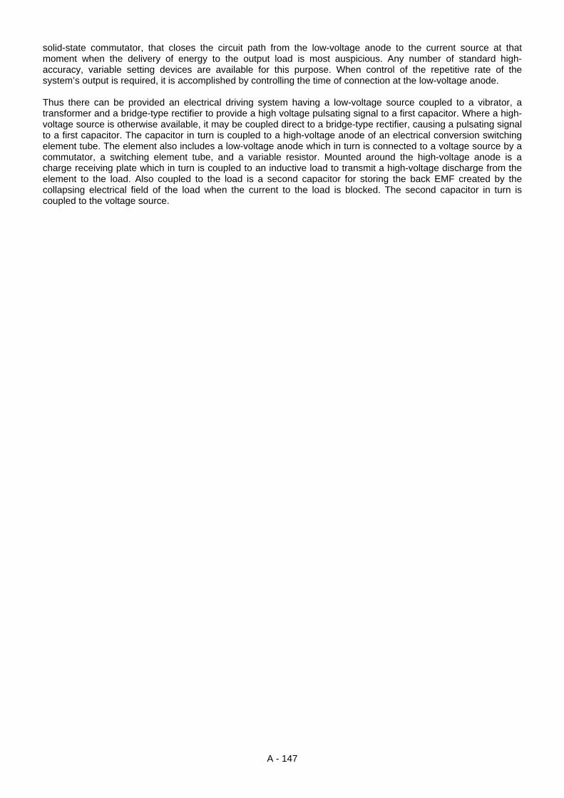
A - 147
solid-state commutator, that closes the circuit path from the low-voltage anode to the current source at that moment when the delivery of energy to the output load is most auspicious. Any number of standard high-accuracy, variable setting devices are available for this purpose. When control of the repetitive rate of the system’s output is required, it is accomplished by controlling the time of connection at the low-voltage anode. Thus there can be provided an electrical driving system having a low-voltage source coupled to a vibrator, a transformer and a bridge-type rectifier to provide a high voltage pulsating signal to a first capacitor. Where a high-voltage source is otherwise available, it may be coupled direct to a bridge-type rectifier, causing a pulsating signal to a first capacitor. The capacitor in turn is coupled to a high-voltage anode of an electrical conversion switching element tube. The element also includes a low-voltage anode which in turn is connected to a voltage source by a commutator, a switching element tube, and a variable resistor. Mounted around the high-voltage anode is a charge receiving plate which in turn is coupled to an inductive load to transmit a high-voltage discharge from the element to the load. Also coupled to the load is a second capacitor for storing the back EMF created by the collapsing electrical field of the load when the current to the load is blocked. The second capacitor in turn is coupled to the voltage source.
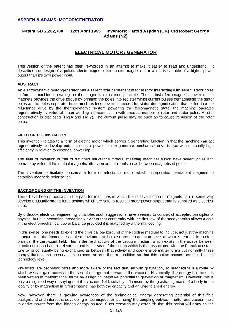
A - 148
ASPDEN & ADAMS: MOTOR/GENERATOR
Patent GB 2,282,708 12th April 1995 Inventors: Harold Aspden (UK) and Robert George Adams (NZ)
ELECTRICAL MOTOR / GENERATOR This version of the patent has been re-worded in an attempt to make it easier to read and understand. It describes the design of a pulsed electromagnet / permanent magnet motor which is capable of a higher power output than it’s own power input. ABSTRACT An electrodynamic motor-generator has a salient pole permanent magnet rotor interacting with salient stator poles to form a machine operating on the magnetic reluctance principle. The intrinsic ferromagnetic power of the magnets provides the drive torque by bringing the poles into register whilst current pulses demagnetise the stator poles as the poles separate. In as much as less power is needed for stator demagnetisation than is fed into the reluctance drive by the thermodynamic system powering the ferromagnetic state, the machine operates regeneratively by virtue of stator winding interconnection with unequal number of rotor and stator poles. A rotor construction is disclosed (Fig.6 and Fig.7). The current pulse may be such as to cause repulsion of the rotor poles. FIELD OF THE INVENTION This invention relates to a form of electric motor which serves a generating function in that the machine can act regeneratively to develop output electrical power or can generate mechanical drive torque with unusually high efficiency in relation to electrical power input. The field of invention is that of switched reluctance motors, meaning machines which have salient poles and operate by virtue of the mutual magnetic attraction and/or repulsion as between magnetised poles. The invention particularly concerns a form of reluctance motor which incorporates permanent magnets to establish magnetic polarisation. BACKGROUND OF THE INVENTION There have been proposals in the past for machines in which the relative motion of magnets can in some way develop unusually strong force actions which are said to result in more power output than is supplied as electrical input. By orthodox electrical engineering principles such suggestions have seemed to contradict accepted principles of physics, but it is becoming increasingly evident that conformity with the first law of thermodynamics allows a gain in the electromechanical power balance provided it is matched by a thermal cooling. In this sense, one needs to extend the physical background of the cooling medium to include, not just the machine structure and the immediate ambient environment, but also the sub-quantum level of what is termed, in modern physics, the zero-point field. This is the field activity of the vacuum medium which exists in the space between atomic nuclei and atomic electrons and is the seat of the action which is that associated with the Planck constant. Energy is constantly being exchanged as between that activity and coextensive matter forms but normally these energy fluctuations preserve, on balance, an equilibrium condition so that this action passes unnoticed at the technology level. Physicists are becoming more and more aware of the fact that, as with gravitation, so magnetism is a route by which we can gain access to the sea of energy that pervades the vacuum. Historically, the energy balance has been written in mathematical terms by assigning 'negative' potential to gravitation or magnetism. However, this is only a disguised way of saying that the vacuum field, suitably influenced by the gravitating mass of a body in the locality or by magnetism in a ferromagnet has both the capacity and an urge to shed energy. Now, however, there is growing awareness of the technological energy generating potential of this field background and interest is developing in techniques for 'pumping' the coupling between matter and vacuum field to derive power from that hidden energy source. Such research may establish that this action will draw on the

A - 149
2.7K cosmic background temperature of the space medium through which the Earth travels at some 400 km/s. The effect contemplated could well leave a cool 'vapour trail' in space as a machine delivering heat, or delivering a more useful electrical form of energy that will revert to heat, travels with body Earth through that space. In pure physics terms, relevant background is of recent record in the August 1993 issue of Physical Review E, vol. 48, pp. 1562-1565 under the title: 'Extracting energy and heat from the vacuum', authored by D. C. Cole and H. E. Puthoff. Though the connection is not referenced in that paper, one of its author's presented experimental evidence on that theme at an April 1993 conference held in Denver USA. The plasma power generating device discussed at that conference was the subject of U. S. Patent No. 5,018,180, the inventor of record being K. R. Shoulders. The invention, to be described below, operates by extracting energy from a magnetic system in a motor and the relevant scientific background to this technology can be appreciated from the teachings of E. B. Moullin, a Cambridge Professor of Electrical Engineering who was a President of the Institution of Electrical Engineers in U. K. That prior art will be described below as part of the explanation of the operation of the invention. The invention presented here concerns specific structural design features of a machine adapted for robust operation, but these also have novelty and special merit in a functional operation. What is described is quite distinct from prior art proposals, one being a novel kind of motor proposed by Gareth Jones at a 1988 symposium held in Hull, Canada under the auspices of the Planetary Association for Clean Energy. Jones suggested the adaptation of an automobile alternator which generates three-phase AC for rectification and use as a power supply for the electrics in the automobile. This alternator has a permanent magnet rotor and Jones suggested that it could be used, with high efficiency gain and torque performance, by operating it as a motor with the three-phase winding circuit excited so as to promote strong repulsion between the magnet poles and the stator poles after the poles had come into register. However, the Jones machine is not one exploiting the advantages of the invention to be described, because it is not strictly a reluctance motor having salient poles on both stator and rotor. The stator poles in the Jones machine are formed by the winding configuration in a slotted stator form, the many slots being uniformly distributed around the inner circumference of the stator and not constituting a pole system which lends itself to the magnetic flux actions to be described by reference to the E. B. Moullin experiment. The Jones machine operates by generating a rotating stator field which, in a sense, pushes the rotor poles forward rather than pulling them in the manner seen in the normal synchronous motor. Accordingly, the Jones machine relies on the electric current excitation of the motor producing a field system which rotates smoothly but has a polarity pattern which is forced by the commutation control to keep behind the rotor poles in asserting a continuous repulsive drive. Another prior art proposal which is distinguished from this invention is that of one of the applicants, H. Aspden, namely the subject of U.K. Patent No. 2,234,863 (counterpart U.S. Patent Serial No.4,975,608). Although this latter invention is concerned with extracting energy from the field by the same physical process as the subject invention, the technique for accessing that energy is not optimum in respect of the structure or method used. Whereas in this earlier disclosure, the switching of the reluctance drive excited the poles in their approach phase, the subject invention, in one of its aspects, offers distinct advantages by demagnetisation or reversal of magnetisation in the pole separation phase of operation. There are unexpected advantages in the implementation proposed by the subject invention, inasmuch as recent research has confirmed that it requires less input power to switch off the mutual attraction across an air gap between a magnet and an electromagnet than it does to switch it on. Usually, in electromagnetism, a reversal symmetry is expected, arising from conventional teaching of the way forward and back magnetomotive forces govern the resulting flux in a magnetic circuit. This will be further explained after describing the scope of the invention. BRIEF DESCRIPTION OF THE INVENTION According to one aspect of the invention, an electrodynamic motor/generator machine comprises a stator configured to provide a set of stator poles, a corresponding set of magnetising windings mounted on the stator pole set, a rotor having two sections each of which has a set of salient pole pieces, the rotor sections being axially spaced along the axis of rotation of the rotor, rotor magnetisation means disposed between the two rotor sections arranged to produce a unidirectional magnetic field which magnetically polarises the rotor poles, whereby the pole faces of one rotor section all have a north polarity and the pole faces of the other rotor section all have a south polarity and electric circuit connections between an electric current source and the stator magnetising windings arranged to regulate the operation of the machine by admitting current pulses for a duration determined according

A - 150
to the angular position of the rotor, which pulses have a direction tending to oppose the polarisation induced in the stator by the rotor polarisation as stator and rotor poles separate from an in-register position, whereby the action of the rotor magnetisation means provides a reluctance motor drive force to bring stator and rotor poles into register and the action of the stator magnetisation windings opposes the counterpart reluctance braking effect as the poles separate. According to a feature of the invention, the circuit connecting the electric current source and the stator magnetising windings is designed to deliver current pulses which are of sufficient strength and duration to provide demagnetisation of the stator poles as the stator and rotor poles separate from an in-register position. In this regard it is noted that in order to suppress the reluctance drive torque or brake torque, depending upon whether poles are converging or separating, a certain amount of electrical power must be fed to the magnetising windings on the stator. In a sense these windings are really 'demagnetising windings' because the polarity of the circuit connections admit the pulse current in the demagnetising direction. However, it is more usual to refer to windings on magnetic cores as 'magnetising windings' even though they can function as primary windings or secondary windings, the former serving the magnetisation function with input power and the latter serving a demagnetising function with return of power. According to another feature of the invention, the circuit connecting the electric current source and the stator magnetising windings is designed to deliver current pulses which are of sufficient strength and duration to provide a reversal of magnetic flux direction in the stator poles as the stator and rotor poles separate from an in-register position, whereby to draw on power supplied from the electric current source to provide additional forward drive torque. According to a further feature of the invention, the electric current source connected to a stator magnetising winding of a first stator pole comprises, at least partially, the electrical pulses induced in the stator magnetising winding of a different second stator pole, the stator pole set configuration in relation to the rotor pole set configuration being such that the first stator pole is coming into register with a rotor pole as the second stator pole separates from its in-register position with a rotor pole. This means that the magnetising windings of two stator poles are connected so that both serve a 'demagnetising' function, one in resisting the magnetic action of the mutual attraction in pulling poles into register, an action which develops a current pulse output and one in absorbing this current pulse, again by resisting the magnetic inter-pole action to demagnetise the stator pole as its associated rotor pole separates. In order to facilitate the function governed by this circuit connection between stator magnetising windings, a phase difference is needed and this is introduced by designing the machine to have a different number of poles in a set of stator poles from the number of rotor poles in each rotor section. Together with the dual rotor section feature, this has the additional merit of assuring a smoother torque action and reducing magnetic flux fluctuations and leakage effects which contribute substantially to machine efficiency. Thus, according to another feature of the invention, the stator configuration provides pole pieces which are common to both rotor sections in the sense that when stator and rotor poles are in-register the stator pole pieces constitute bridging members for magnetic flux closure in a magnetic circuit including that of the rotor magnetisation means disposed between the two rotor sections. Preferably, the number of poles in a set of stator poles and the number of rotor poles in each section do not share a common integer factor, the number of rotor poles in one rotor section is the same as that in the other rotor section and the number of poles in a stator set and the number of poles in a rotor section differs by one, with the pole faces being of sufficient angular width to assure that the magnetic flux produced by the rotor magnetisation means can find a circular magnetic flux closure route through the bridging path of a stator pole and through corresponding rotor poles for any angular position of the rotor. It is also preferable from a design viewpoint for the stator pole faces of this invention to have an angular width that is no greater than half the angular width of a rotor pole and for the rotor sections to comprise circular steel laminations in which the rotor poles are formed as large teeth at the perimeter with the rotor magnetisation means comprising a magnetic core structure the end faces of which abut two assemblies of such laminations forming the two rotor sections. According to a further feature of the invention, the rotor magnetisation means comprises at least one permanent magnet located with its polarisation axis parallel with the rotor axis. The motor-generator may include an apertured metal disc that is of a non-magnetisable substance mounted on a rotor shaft and positioned intermediate the two rotor sections, each aperture providing location for a permanent magnet, whereby the centrifugal forces acting on the permanent magnet as the rotor rotates are absorbed by the stresses set up in the
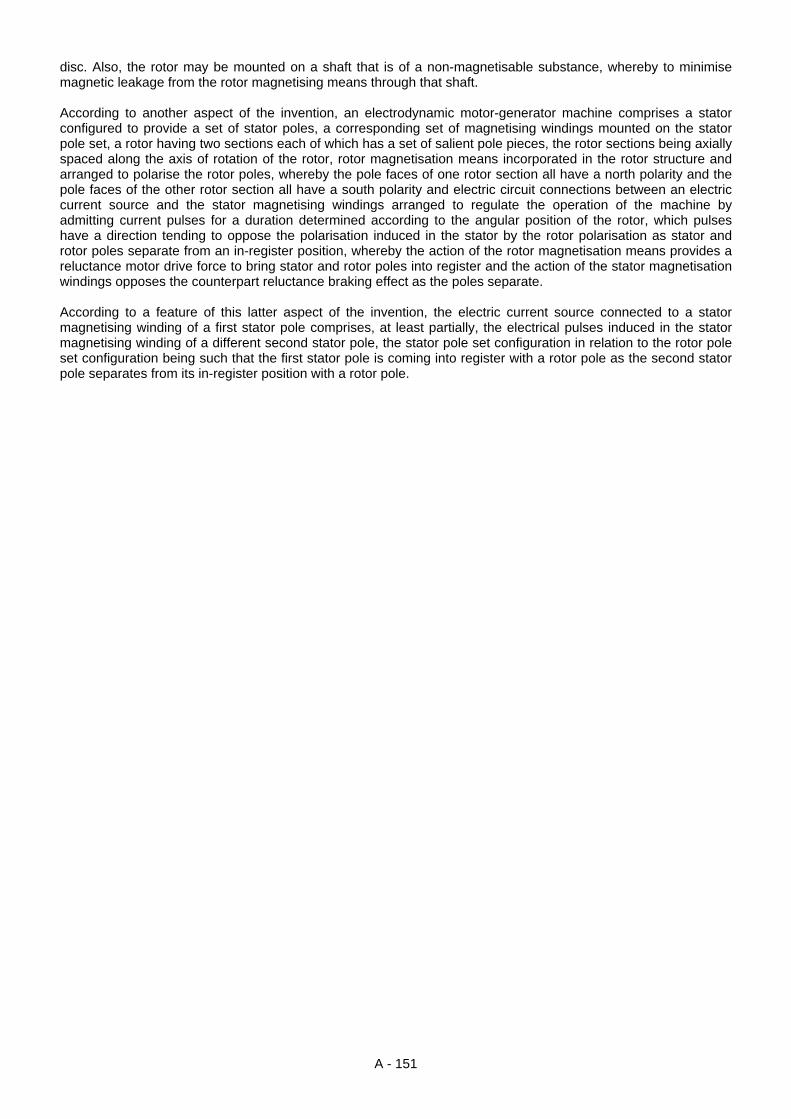
A - 151
disc. Also, the rotor may be mounted on a shaft that is of a non-magnetisable substance, whereby to minimise magnetic leakage from the rotor magnetising means through that shaft. According to another aspect of the invention, an electrodynamic motor-generator machine comprises a stator configured to provide a set of stator poles, a corresponding set of magnetising windings mounted on the stator pole set, a rotor having two sections each of which has a set of salient pole pieces, the rotor sections being axially spaced along the axis of rotation of the rotor, rotor magnetisation means incorporated in the rotor structure and arranged to polarise the rotor poles, whereby the pole faces of one rotor section all have a north polarity and the pole faces of the other rotor section all have a south polarity and electric circuit connections between an electric current source and the stator magnetising windings arranged to regulate the operation of the machine by admitting current pulses for a duration determined according to the angular position of the rotor, which pulses have a direction tending to oppose the polarisation induced in the stator by the rotor polarisation as stator and rotor poles separate from an in-register position, whereby the action of the rotor magnetisation means provides a reluctance motor drive force to bring stator and rotor poles into register and the action of the stator magnetisation windings opposes the counterpart reluctance braking effect as the poles separate. According to a feature of this latter aspect of the invention, the electric current source connected to a stator magnetising winding of a first stator pole comprises, at least partially, the electrical pulses induced in the stator magnetising winding of a different second stator pole, the stator pole set configuration in relation to the rotor pole set configuration being such that the first stator pole is coming into register with a rotor pole as the second stator pole separates from its in-register position with a rotor pole.
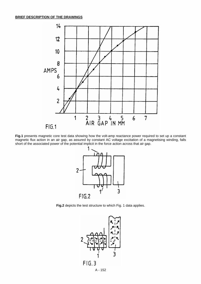
A - 152
BRIEF DESCRIPTION OF THE DRAWINGS
Fig.1 presents magnetic core test data showing how the volt-amp reactance power required to set up a constant magnetic flux action in an air gap, as assured by constant AC voltage excitation of a magnetising winding, falls short of the associated power of the potential implicit in the force action across that air gap.
Fig.2 depicts the test structure to which Fig. 1 data applies.
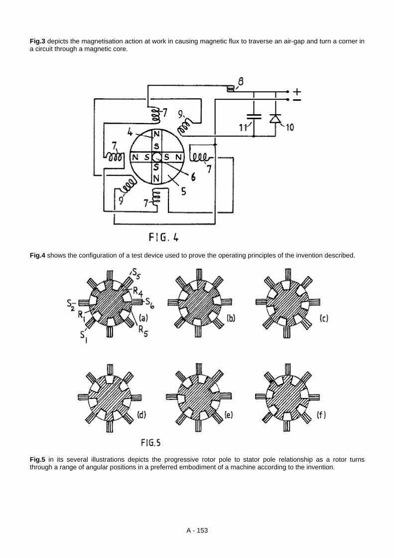
A - 153
Fig.3 depicts the magnetisation action at work in causing magnetic flux to traverse an air-gap and turn a corner in a circuit through a magnetic core.
Fig.4 shows the configuration of a test device used to prove the operating principles of the invention described.
Fig.5 in its several illustrations depicts the progressive rotor pole to stator pole relationship as a rotor turns through a range of angular positions in a preferred embodiment of a machine according to the invention.
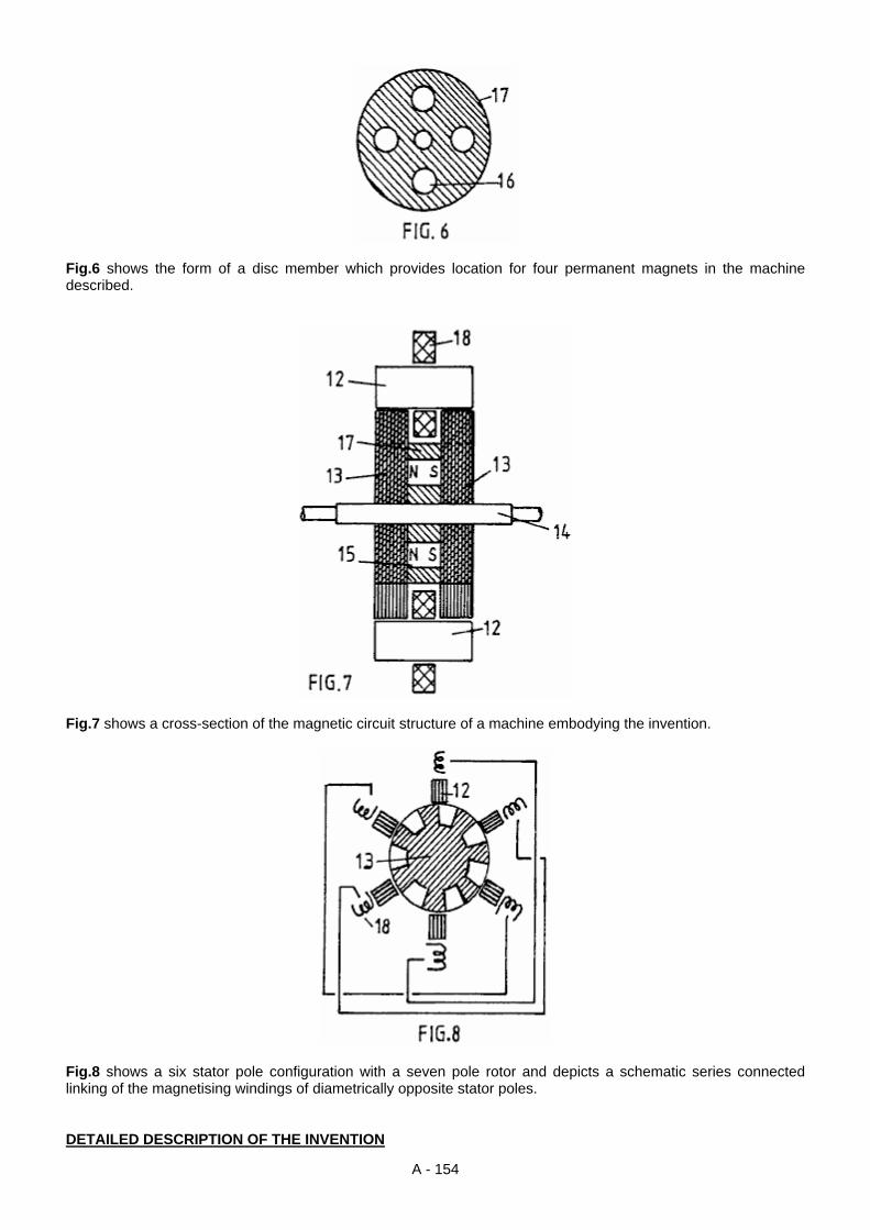
A - 154
Fig.6 shows the form of a disc member which provides location for four permanent magnets in the machine described.
Fig.7 shows a cross-section of the magnetic circuit structure of a machine embodying the invention.
Fig.8 shows a six stator pole configuration with a seven pole rotor and depicts a schematic series connected linking of the magnetising windings of diametrically opposite stator poles. DETAILED DESCRIPTION OF THE INVENTION
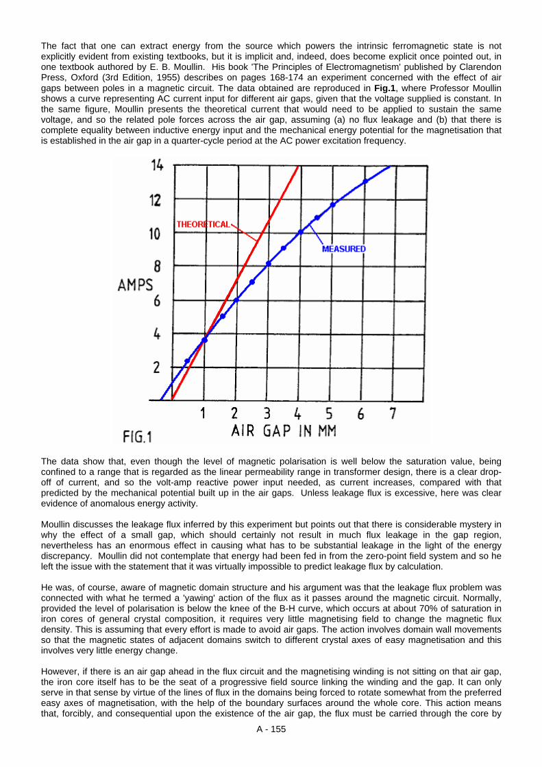
A - 155
The fact that one can extract energy from the source which powers the intrinsic ferromagnetic state is not explicitly evident from existing textbooks, but it is implicit and, indeed, does become explicit once pointed out, in one textbook authored by E. B. Moullin. His book 'The Principles of Electromagnetism' published by Clarendon Press, Oxford (3rd Edition, 1955) describes on pages 168-174 an experiment concerned with the effect of air gaps between poles in a magnetic circuit. The data obtained are reproduced in Fig.1, where Professor Moullin shows a curve representing AC current input for different air gaps, given that the voltage supplied is constant. In the same figure, Moullin presents the theoretical current that would need to be applied to sustain the same voltage, and so the related pole forces across the air gap, assuming (a) no flux leakage and (b) that there is complete equality between inductive energy input and the mechanical energy potential for the magnetisation that is established in the air gap in a quarter-cycle period at the AC power excitation frequency.
The data show that, even though the level of magnetic polarisation is well below the saturation value, being confined to a range that is regarded as the linear permeability range in transformer design, there is a clear drop-off of current, and so the volt-amp reactive power input needed, as current increases, compared with that predicted by the mechanical potential built up in the air gaps. Unless leakage flux is excessive, here was clear evidence of anomalous energy activity. Moullin discusses the leakage flux inferred by this experiment but points out that there is considerable mystery in why the effect of a small gap, which should certainly not result in much flux leakage in the gap region, nevertheless has an enormous effect in causing what has to be substantial leakage in the light of the energy discrepancy. Moullin did not contemplate that energy had been fed in from the zero-point field system and so he left the issue with the statement that it was virtually impossible to predict leakage flux by calculation. He was, of course, aware of magnetic domain structure and his argument was that the leakage flux problem was connected with what he termed a 'yawing' action of the flux as it passes around the magnetic circuit. Normally, provided the level of polarisation is below the knee of the B-H curve, which occurs at about 70% of saturation in iron cores of general crystal composition, it requires very little magnetising field to change the magnetic flux density. This is assuming that every effort is made to avoid air gaps. The action involves domain wall movements so that the magnetic states of adjacent domains switch to different crystal axes of easy magnetisation and this involves very little energy change. However, if there is an air gap ahead in the flux circuit and the magnetising winding is not sitting on that air gap, the iron core itself has to be the seat of a progressive field source linking the winding and the gap. It can only serve in that sense by virtue of the lines of flux in the domains being forced to rotate somewhat from the preferred easy axes of magnetisation, with the help of the boundary surfaces around the whole core. This action means that, forcibly, and consequential upon the existence of the air gap, the flux must be carried through the core by
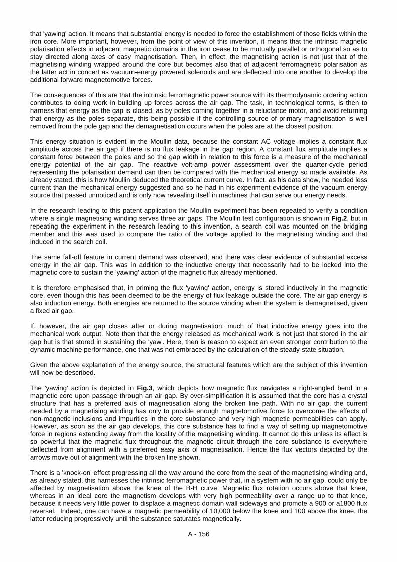
A - 156
that 'yawing' action. It means that substantial energy is needed to force the establishment of those fields within the iron core. More important, however, from the point of view of this invention, it means that the intrinsic magnetic polarisation effects in adjacent magnetic domains in the iron cease to be mutually parallel or orthogonal so as to stay directed along axes of easy magnetisation. Then, in effect, the magnetising action is not just that of the magnetising winding wrapped around the core but becomes also that of adjacent ferromagnetic polarisation as the latter act in concert as vacuum-energy powered solenoids and are deflected into one another to develop the additional forward magnetomotive forces. The consequences of this are that the intrinsic ferromagnetic power source with its thermodynamic ordering action contributes to doing work in building up forces across the air gap. The task, in technological terms, is then to harness that energy as the gap is closed, as by poles coming together in a reluctance motor, and avoid returning that energy as the poles separate, this being possible if the controlling source of primary magnetisation is well removed from the pole gap and the demagnetisation occurs when the poles are at the closest position. This energy situation is evident in the Moullin data, because the constant AC voltage implies a constant flux amplitude across the air gap if there is no flux leakage in the gap region. A constant flux amplitude implies a constant force between the poles and so the gap width in relation to this force is a measure of the mechanical energy potential of the air gap. The reactive volt-amp power assessment over the quarter-cycle period representing the polarisation demand can then be compared with the mechanical energy so made available. As already stated, this is how Moullin deduced the theoretical current curve. In fact, as his data show, he needed less current than the mechanical energy suggested and so he had in his experiment evidence of the vacuum energy source that passed unnoticed and is only now revealing itself in machines that can serve our energy needs. In the research leading to this patent application the Moullin experiment has been repeated to verify a condition where a single magnetising winding serves three air gaps. The Moullin test configuration is shown in Fig.2, but in repeating the experiment in the research leading to this invention, a search coil was mounted on the bridging member and this was used to compare the ratio of the voltage applied to the magnetising winding and that induced in the search coil. The same fall-off feature in current demand was observed, and there was clear evidence of substantial excess energy in the air gap. This was in addition to the inductive energy that necessarily had to be locked into the magnetic core to sustain the 'yawing' action of the magnetic flux already mentioned. It is therefore emphasised that, in priming the flux 'yawing' action, energy is stored inductively in the magnetic core, even though this has been deemed to be the energy of flux leakage outside the core. The air gap energy is also induction energy. Both energies are returned to the source winding when the system is demagnetised, given a fixed air gap. If, however, the air gap closes after or during magnetisation, much of that inductive energy goes into the mechanical work output. Note then that the energy released as mechanical work is not just that stored in the air gap but is that stored in sustaining the 'yaw'. Here, then is reason to expect an even stronger contribution to the dynamic machine performance, one that was not embraced by the calculation of the steady-state situation. Given the above explanation of the energy source, the structural features which are the subject of this invention will now be described. The 'yawing' action is depicted in Fig.3, which depicts how magnetic flux navigates a right-angled bend in a magnetic core upon passage through an air gap. By over-simplification it is assumed that the core has a crystal structure that has a preferred axis of magnetisation along the broken line path. With no air gap, the current needed by a magnetising winding has only to provide enough magnetomotive force to overcome the effects of non-magnetic inclusions and impurities in the core substance and very high magnetic permeabilities can apply. However, as soon as the air gap develops, this core substance has to find a way of setting up magnetomotive force in regions extending away from the locality of the magnetising winding. It cannot do this unless its effect is so powerful that the magnetic flux throughout the magnetic circuit through the core substance is everywhere deflected from alignment with a preferred easy axis of magnetisation. Hence the flux vectors depicted by the arrows move out of alignment with the broken line shown. There is a 'knock-on' effect progressing all the way around the core from the seat of the magnetising winding and, as already stated, this harnesses the intrinsic ferromagnetic power that, in a system with no air gap, could only be affected by magnetisation above the knee of the B-H curve. Magnetic flux rotation occurs above that knee, whereas in an ideal core the magnetism develops with very high permeability over a range up to that knee, because it needs very little power to displace a magnetic domain wall sideways and promote a 900 or a1800 flux reversal. Indeed, one can have a magnetic permeability of 10,000 below the knee and 100 above the knee, the latter reducing progressively until the substance saturates magnetically.

A - 157
In the situation depicted in Fig.2 and Fig.3 the field strength developed by the magnetising windings 1 on magnetic core 2 has to be higher, the greater the air gap, in order to achieve the same amount of magnetisation as measured by the voltage induced in a winding (not shown) on the bridging member 3. However, by virtue of that air gap there is potential for harnessing energy supplied to that air gap by the intrinsic zero-point field that accounts for the magnetic permeability being over unity and here one can contemplate very substantial excess energy potential, given incorporation in a machine design which departs from convention. One of the applicants has built an operative test machine which is configured as depicted schematically in Fig.4. The machine has been proved to deliver substantially more mechanical power output than is supplied as electrical input, as much as a ratio of 7:1 in one version, and it can act regeneratively to produce electrical power.
What is shown in Fig.4 is a simple model designed to demonstrate the principle of operation. It comprises a rotor in which four permanent magnets 4 are arrayed to form four poles. The magnets are bonded into four sectors of a non-magnetic disc 5 using a high density polyurethane foam filler and the composite disc is then assembled on a brass spindle 6 between a split flange coupling. Not shown in the figure is the structure holding the spindle vertically in bearings or the star wheel commutator assembly attached to the upper shaft of the spindle. Note that the magnets present north poles at the perimeter of the rotor disc and that the south poles are held together by being firmly set in the bonding material. A series of four stator poles were formed using magnetic cores from standard electromagnetic relays are were positioned around the rotor disc as shown. The magnetising windings 7 on these cores are shown to be connected in series and powered through commutator contacts 8 by a DC power supply. Two further stator cores formed by similar electromagnetic relay components are depicted by their windings 9 in the intermediate angle positions shown and these are connected in series and connected to a rectifier 10 bridged by a capacitor 11.

A - 158
The rotor spindle 6 is coupled with a mechanical drive (not shown) which harnesses the torque developed by the motor thus formed and serves as a means for measuring output mechanical power delivered by the machine. In operation, assuming that the rotor poles are held initially off-register with the corresponding stator poles and the hold is then released, the strong magnetic field action of the permanent magnets will turn the rotor to bring the stator and rotor poles into register. A permanent magnet has a strong attraction for soft iron and so this initial impulse of rotation is powered by the potential energy of the magnets. Now, with the rotor acting as a flywheel and having inertia it will have a tendency to over-shoot the in-register pole position and that will involve a reverse attraction with the result that the rotor will oscillate until damping action brings it to rest. However, if the contacts of the commutating switch are closed as the poles come The commutating switch 8 needs only to be closed for a limited period of angular travel following the top dead centre in-register position of the stator and rotor poles. The power supplied through that switch by those pulses will cause the rotor to continue rotating and high speeds will be achieved as the machine develops its full motor function. Tests on such a machine have shown that more mechanical power can be delivered than is supplied electrically by the source powering the action through the commutating switch. The reason for this is that, whereas the energy in the air gap between rotor and stator poles which is tapped mechanically as the poles come into register is provided by the intrinsic power of the ferromagnet, a demagnetising winding on the part of the core system coupled across that air gap needs very little power to eliminate the mechanical force acting across that air gap. Imagine such a winding on the bridging member shown in Fig.2. The action of current in that winding, which sits astride the 'yawing' flux in that bridging member well removed from the source action of the magnetising windings 1, is placed to be extremely effective in resisting the magnetising influence communicated from a distance. Hence very little power is needed to overcome the magnetic coupling transmitted across the air gap. Although the mutual inductance between two spaced-apart magnetising windings has a reciprocal action, regardless of which winding is primary and which is secondary, the action in the particular machine situation being described involves the 'solenoidal' contribution represented by the 'yawing' ferromagnetic flux action. The latter is not reciprocal inasmuch as the flux ‘yaw' depends on the geometry of the system. A magnetising winding directing flux directly across an air gap has a different influence on the action in the ferromagnetic core from one directing flux lateral to the air gap and there is no reciprocity in this action. In any event, the facts of experiment do reveal that, owing to a significant discrepancy in such mutual interaction, more mechanical power is fed into the rotor than is supplied as input from the electrical source. This has been further demonstrated by using the two stator windings 9 to respond in a generator sense to the passage of the rotor poles. An electrical pulse is induced in each winding by the passage of a rotor pole and this is powered by the inertia of the rotor disc 5. By connecting the power so generated, to charge the capacitor 11, the DC power supply can be augmented to enhance the efficiency even further. Indeed, the machine is able to demonstrate the excess power delivery from the ferromagnetic system by virtue of electrical power generation charging a battery at a greater rate than a supply battery is discharged. This invention is concerned with a practical embodiment of the motor-generator principles just described and aims, in its preferred aspect, to provide a robust and reliable machine in which the tooth stresses in the rotor poles, which are fluctuating stresses communicating high reluctance drive torque, are not absorbed by a ceramic permanent magnet liable to rupture owing to its brittle composition. Another object is to provide a structure which can be dismantled and reassembled easily to replace the permanent magnets, but an even more important object is that of minimising the stray leakage flux oscillations from the powerful permanent magnets. Their rotation in the device depicted in Fig.4 would cause excessive eddy-current induction in nearby metal, including that of the machine itself, and such effects are minimised if the flux changes are confined to paths through steel laminations and if the source flux from the magnets has a symmetry or near symmetry about the axis of rotation. Thus, the ideal design with this in mind is one where the permanent magnet is a hollow cylinder located on a non-magnetic rotor shaft, but, though that structure is within the scope of this invention, the machine described will utilise several separate permanent magnets approximating, in function, such a cylindrical configuration. Referring to Fig.4, it will further be noted that the magnetic flux emerging from the north poles will have to find its way along leakage paths through air to re-enter the south poles. For periods in each cycle of machine operation

A - 159
the flux will be attracted through the stator cores, but the passage through air is essential and so the power of the magnets is not used to full advantage and there are those unwanted eddy-current effects. To overcome this problem the invention provides for two separate rotor sections and the stator poles become bridging members, which with optimum design, allow the flux from the magnets to find a route around a magnetic circuit with minimal leakage through air as the flux is directed through one or other pairs of air gaps where the torque action is developed.
Reference is now made to Fig.5 and the sequence of rotor positions shown. Note that the stator pole width can be significantly smaller that that of the rotor poles. Indeed, for operation using the principles of this invention, it is advantageous for the stator to have a much smaller pole width so as to concentrate the effective pole region. A stator pole width of half that of the rotor is appropriate but it may be even smaller and this has the secondary advantage of requiring smaller magnetising windings and so saving on the loss associated with the current circuit.
The stator has eight pole pieces formed as bridging members 12, more clearly represented in Fig.7, which shows a sectional side view through two rotor sections 13 axially spaced on a rotor shaft 14. There are four permanent magnets 15 positioned between these rotor sections and located in apertures 16 in a disc 17 of a non-magnetic

A - 160
substance of high tensile strength, the latter being shown in Fig.6. The rotor sections are formed from disc laminations of electrical steel which has seven large teeth, the salient poles. Magnetising windings 18 mounted on the bridging members 12 constitute the system governing the action of the motor-generator being described. The control circuitry is not described as design of such circuitry involves ordinary skill possessed by those involved in the electrical engineering art. It suffices, therefore, to describe the merits of the structural design configuration of the core elements of the machine. These concern principally the magnetic action and, as can be imagined from Fig.7, the magnetic flux from the magnets enters the rotor laminations by traversing the planar faces of the laminations and being deflected into the plane of the laminations to pass through one or other of the stator pole bridging members, returning by a similar route through the other rotor. By using eight stator poles and seven rotor poles, the latter having a pole width equal to half the pole pitch in an angular sense, it will be seen from Fig.5, that there is always a flux passage across the small air gap between stator and rotor poles. However, as one pole combination is in-register the diametrically-opposed pole combinations are out-of register. As described by reference to Fig.4 the operation of the machine involves allowing the magnet to pull stator and rotor poles into register and then, as they separate, pulsing the winding on the relevant stator member to demagnetise that member. In the Fig.4 system, all the stator magnetising windings were pulsed together, which is not an optimum way in which to drive a multi-pole machine. In the machine having the pole structure with one less rotor pole than stator poles (or an equivalent design in which there is one less stator pole than rotor poles) this pulsing action can be distributed in its demand on the power supply, and though this makes the commutation switch circuit more expensive the resulting benefit outweighs that cost. However, there is a feature of this invention by which that problem can be alleviated if not eliminated. Suppose that the rotor has the position shown in Fig.5(a) with the rotor pole denoted R1 midway between stator poles S1 and S2 and imagine that this is attracted towards the in-register position with stator pole S2. Upon reaching that in-register position, as shown in Fig.5(c), suppose that the magnetising winding of stator pole S2 is excited by a current pulse which is sustained until the rotor reaches the Fig.5(e) position. The combination of these two actions will have imparted a forward drive impulse powered by the permanent magnet in the rotor structure and the current pulse which suppresses braking action will have drawn a smaller amount of energy from the electrical power source which supplies it. This is the same process as was described by reference to Fig.4. However, now consider the events occurring in the rotor action diametrically opposite that just described. In the Fig.5(a) position rotor pole R4 has come fully into register with stator pole S5 and so stator pole S5 is ready to be demagnetised. However, the magnetic coupling between the rotor and stator poles is then at its strongest. Note, however, that in that Fig.5(a) position R5 is beginning its separation from stator poles and the magnetising winding of stator pole S6 must then begin draw power to initiate demagnetisation. During that following period of pole separation the power from the magnet is pulling R1 and S2 together with much more action than is needed to generate that current pulse needed to demagnetise S6. It follows, therefore, that, based on the research findings of the regenerative excitation in the test system of Fig.4, the series connection of the magnetising windings on stators S2 and S6 will, without needing any commutative switching, provide the regenerative power needed for machine operation. The complementary action of the two magnetising windings during the pole closure and pole separation allows the construction of a machine which, given that the zero-point vacuum energy powering the ferromagnet is feeding input power, will run on that source of energy and thereby cool the sustaining field system. There are various design options in implementing what has just been proposed. Much depends upon the intended use of the machine. If it is intended to deliver mechanical power output the regenerative electrical power action can all be used to power the demagnetisation with any surplus contributing to a stronger drive torque by reversing the polarity of the stator poles during pole separation. If the object is to generate electricity by operating in generator mode then one could design a machine having additional windings on the stator for delivering electrical power output. However, it seems preferable to regard the machine as a motor and maximise its efficiency in that capacity whilst using a mechanical coupling to an alternator of conventional design for the electrical power generation function.
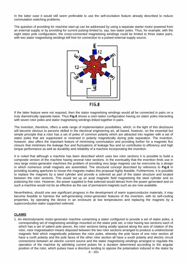
A - 161
In the latter case it would still seem preferable to use the self-excitation feature already described to reduce commutation switching problems. The question of providing for machine start-up can be addressed by using a separate starter motor powered from an external supply or by providing for current pulsing limited to, say, two stator poles. Thus, for example, with the eight stator pole configuration, the cross-connected magnetising windings could be limited to three stator pairs, with two stator magnetising windings left free for connection to a pulsed external supply source.
If the latter feature were not required, then the stator magnetising windings would all be connected in pairs on a truly diametrically opposite basis. Thus Fig.8 shows a rotor-stator configuration having six stator poles interacting with seven rotor poles and stator magnetising windings linked together in pairs. The invention, therefore, offers a wide range of implementation possibilities, which, in the light of this disclosure will become obvious to persons skilled in the electrical engineering art, all based, however, on the essential but simple principle that a rotor has a set of poles of common polarity which are attracted into register with a set of stator poles that are suppressed or reversed in polarity magnetically during pole separation. The invention, however, also offers the important feature of minimising commutation and providing further for a magnetic flux closure that minimises the leakage flux and fluctuations of leakage flux and so contributes to efficiency and high torque performance as well as durability and reliability of a machine incorporating the invention. It is noted that although a machine has been described which uses two rotor sections it is possible to build a composite version of the machine having several rotor sections. In the eventuality that the invention finds use in very large motor-generator machines the problem of providing very large magnets can be overcome by a design in which numerous small magnets are assembled. The structural concept described by reference to Fig.6 in providing locating apertures to house the magnets makes this proposal highly feasible. Furthermore, it is possible to replace the magnets by a steel cylinder and provide a solenoid as part of the stator structure and located between the rotor sections. This would set up an axial magnetic field magnetising the steel cylinder and so polarising the rotor. However, the power supplied to that solenoid would detract from the power generated and so such a machine would not be as effective as the use of permanent magnets such as are now available. Nevertheless, should one see significant progress in the development of warm superconductor materials, it may become feasible to harness the self-generating motor-generator features of the invention, with its self-cooling properties, by operating the device in an enclosure at low temperatures and replacing the magnets by a superconductive stator supported solenoid. CLAIMS 1. An electrodynamic motor-generator machine comprising a stator configured to provide a set of stator poles, a
corresponding set of magnetising windings mounted on the stator pole set, a rotor having two sections each of which has a set of salient pole pieces, the rotor sections being axially spaced along the axis of rotation of the rotor, rotor magnetisation means disposed between the two rotor sections arranged to produce a unidirectional magnetic field which magnetically polarises the rotor poles, whereby the pole faces of one rotor section all have a north polarity and the pole faces of the other rotor section all have a south polarity and electric circuit connections between an electric current source and the stator magnetising windings arranged to regulate the operation of the machine by admitting current pulses for a duration determined according to the angular position of the rotor, which pulses have a direction tending to oppose the polarisation induced in the stator by

A - 162
the rotor polarisation as stator and rotor poles separate from an in-register position, whereby the action of the rotor magnetisation means provides a reluctance motor drive force to bring stator and rotor poles into register and the action of the stator magnetisation windings opposes the counterpart reluctance braking effect as the poles separate.
2. A motor-generator according to claim 1, wherein the circuit connecting the electric current source and the stator
magnetising windings is designed to deliver current pulses which are of sufficient strength and duration to provide demagnetisation of the stator poles as the stator and rotor poles separate from an in-register position.
3. A motor-generator according to claim 1, wherein the circuit connecting the electric current source and the stator
magnetising windings is designed to deliver current pulses which are of sufficient strength and duration to provide a reversal of magnetic flux direction in the stator poles as the stator and rotor poles separate from an in-register position, whereby to draw on power supplied from the electric current source to provide additional forward drive torque.
4. A motor-generator according to claim 1, wherein the electric current source connected to a stator magnetising
winding of a first stator pole comprises, at least partially, the electrical pulses induced in the stator magnetising winding of a different second stator pole, the stator pole set configuration in relation to the rotor pole set configuration being such that the first stator pole is coming into register with a rotor pole as the second stator pole separates from its in-register position with a rotor pole.
5. A motor-generator according to claim 1, wherein the number of poles in a set of stator poles is different from
the number of rotor poles in each rotor section. 6. A motor-generator according to claim 1, wherein the stator configuration provides pole pieces which are
common to both rotor sections in the sense that when stator and rotor poles are in-register the stator pole pieces constitute bridging members for magnetic flux closure in a magnetic circuit including that of the rotor magnetisation means disposed between the two rotor sections.
7. A motor-generator according to claim 6, wherein the number of poles in a set of stator poles and the number of
rotor poles in each section do not share a common integer factor and the number of rotor poles in one rotor section is the same as that in the other rotor section.
8. A motor-generator according to claim 7, wherein the number of poles in a stator set and the number of poles in
a rotor section differs by one and the pole faces are of sufficient angular width to assure that the magnetic flux produced by the rotor magnetisation means can find a circuital magnetic flux closure route through the bridging path of a stator pole and through corresponding rotor poles for any angular position of the rotor.
9. A motor-generator according to claim 8, wherein each rotor section comprises seven poles. 10. A motor-generator according to claim 7, wherein there are N rotor poles in each rotor section and each has an
angular width that is 180/N degree of angle. 11. A motor-generator according to claim 7, wherein the stator pole faces have an angular width that is no greater
than half the angular width of a rotor pole. 12. A motor-generator according to claim 1, wherein the rotor sections comprise circular steel laminations in which
the rotor poles are formed as large teeth at the perimeter, and the rotor magnetisation means comprise a magnetic core structure the end faces of which abut two assemblies of such laminations forming the two rotor sections.
13. A motor-generator according to claim 1 in which the rotor magnetisation means comprises at least one
permanent magnet located with its polarisation axis parallel with the rotor axis. 14. A motor-generator according to claim 13, wherein an apertured metal disc that is of a non-magnetisable
substance is mounted on a rotor shaft and positioned intermediate the two rotor sections and each aperture provides location for a permanent magnet, whereby the centrifugal forces acting on the permanent magnet as the rotor rotates are absorbed by the stresses set up in the disc.
15. A motor-generator according to claim 1, having a rotor mounted on a shaft that is of a non-magnetisable
substance, whereby to minimise magnetic leakage from the rotor magnetising means. 16. An electrodynamic motor-generator machine comprising a stator configured to provide a set of stator poles, a
corresponding set of magnetising windings mounted on the stator pole set, a rotor having two sections each of which has a set of salient pole pieces, the rotor sections being axially spaced along the axis of rotation of the
A - 163
rotor, rotor magnetisation means incorporated in the rotor structure and arranged to polarise the rotor poles, whereby the pole faces of one rotor section all have a north polarity and the pole faces of the other rotor section all have a south polarity and electric circuit connections between an electric current source and the stator magnetising windings arranged to regulate the operation of the machine by admitting current pulses for a duration determined according to the angular position of the rotor, which pulses have a direction tending to oppose the polarisation induced in the stator by the rotor polarisation as stator and rotor poles separate from an in-register position, whereby the action of the rotor magnetisation means provides a reluctance motor drive force to bring stator and rotor poles into register and the action of the stator magnetisation windings opposes the counterpart reluctance braking effect as the poles separate.
17. A motor-generator according to claim 16, wherein the electric current source connected to a stator
magnetising winding of a first stator pole comprises, at least partially, the electrical pulses induced in the stator magnetising winding of a different second stator pole, the stator pole set configuration in relation to the rotor pole set configuration being such that the first stator pole is coming into register with a rotor pole as the second stator pole separates from its in-register position with a rotor pole.
Amendments to the claims have been filed as follows 1. An electrodynamic motor-generator machine comprising
a stator configured to provide a set of stator poles, a corresponding set of magnetising windings mounted on the stator pole set, a rotor having two sections each of which has a set of salient pole pieces, the rotor sections being axially spaced along the axis of rotation of the rotor, rotor magnetisation means disposed between the two rotor sections arranged to produce a unidirectional magnetic field which magnetically polarises the rotor poles, whereby the pole faces of one rotor section all have a north polarity and the pole faces of the other rotor section all have a south polarity and electric circuit connections between an electric current source and the stator magnetising windings arranged to regulate the operation of the machine by admitting current pulses for a duration determined according to the angular position of the rotor, which pulses have a direction tending to oppose the polarisation induced in the stator by the rotor polarisation as stator and rotor poles separate from an in-register position, whereby the action of the rotor magnetisation means provides a reluctance motor drive force to bring stator and rotor poles into register and the action of the stator magnetisation windings opposes the counterpart reluctance braking effect as the poles separate, the machine being characterised in that the stator comprises separate ferromagnetic bridging members mounted parallel with the rotor axis, the ends of which constitute stator poles and the core sections of which provide closure paths operative when the stator and rotor poles are in register to confine magnetic flux developed by the rotor magnetisation means to a stator flux path of restricted cross-section disposed anti-parallel with the unidirectional magnetic field polarisation axis of the rotor magnetising means 2. A motor-generator according to claim 1, wherein the circuit connecting the electric current source and the stator magnetising windings is designed to deliver current pulses which are of sufficient strength and duration to provide demagnetisation of the stator poles as the stator and rotor poles separate from an in-register position.
3. A motor-generator according to claim 1, wherein the circuit connecting the electric current source and the stator
magnetising windings is designed to deliver current pulses which are of sufficient strength and duration to provide a reversal of magnetic flux direction in the stator poles as the stator and rotor poles separate from an in-register position, whereby to draw on power supplied from the electric current source to provide additional forward drive torque.
4. A motor-generator according to claim 1, wherein the electric current source connected to a stator magnetising
winding of a first stator pole comprises, at least partially, the electrical pulses induced in the stator magnetising winding of a different second stator pole, the stator pole set configuration in relation to the rotor pole set configuration being such that the first stator pole is coming into register with a rotor pole as the second stator pole separates from its in-register position with a rotor pole.
5. A motor-generator according to claim 1, wherein the number of poles in a set of stator poles is different from
the number of rotor poles in each rotor section. 6. A motor-generator according to claim 1, wherein the stator configuration provides pole pieces which are
common to both rotor sections in the sense that when stator and rotor poles are in-register the stator pole pieces constitute bridging members for magnetic flux closure in a magnetic circuit including that of the rotor magnetisation means disposed between the two rotor sections.
7. A motor-generator according to claim 6, wherein the number of poles in a set of stator poles and the number of
rotor poles in each section do not share a common integer factor and the number of rotor poles in one rotor section is the same as that in the other rotor section.
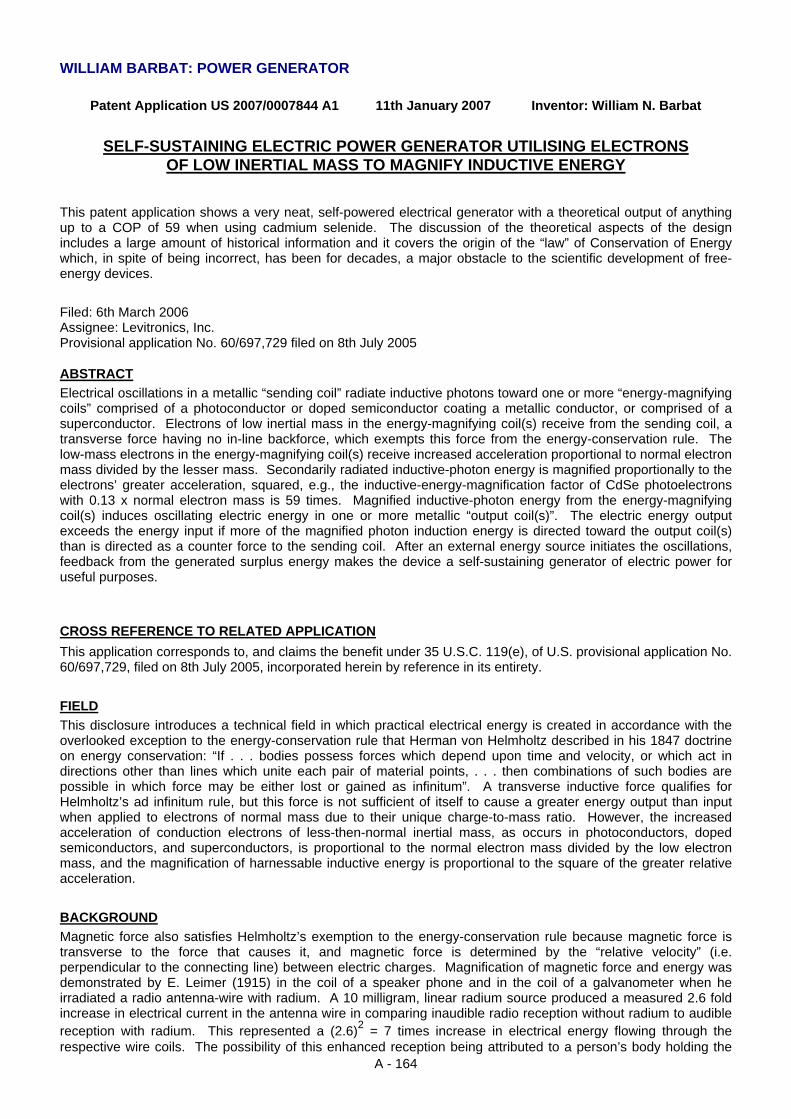
A - 164
WILLIAM BARBAT: POWER GENERATOR
Patent Application US 2007/0007844 A1 11th January 2007 Inventor: William N. Barbat
SELF-SUSTAINING ELECTRIC POWER GENERATOR UTILISING ELECTRONS
OF LOW INERTIAL MASS TO MAGNIFY INDUCTIVE ENERGY This patent application shows a very neat, self-powered electrical generator with a theoretical output of anything up to a COP of 59 when using cadmium selenide. The discussion of the theoretical aspects of the design includes a large amount of historical information and it covers the origin of the “law” of Conservation of Energy which, in spite of being incorrect, has been for decades, a major obstacle to the scientific development of free-energy devices.
Filed: 6th March 2006 Assignee: Levitronics, Inc. Provisional application No. 60/697,729 filed on 8th July 2005 ABSTRACT Electrical oscillations in a metallic “sending coil” radiate inductive photons toward one or more “energy-magnifying coils” comprised of a photoconductor or doped semiconductor coating a metallic conductor, or comprised of a superconductor. Electrons of low inertial mass in the energy-magnifying coil(s) receive from the sending coil, a transverse force having no in-line backforce, which exempts this force from the energy-conservation rule. The low-mass electrons in the energy-magnifying coil(s) receive increased acceleration proportional to normal electron mass divided by the lesser mass. Secondarily radiated inductive-photon energy is magnified proportionally to the electrons’ greater acceleration, squared, e.g., the inductive-energy-magnification factor of CdSe photoelectrons with 0.13 x normal electron mass is 59 times. Magnified inductive-photon energy from the energy-magnifying coil(s) induces oscillating electric energy in one or more metallic “output coil(s)”. The electric energy output exceeds the energy input if more of the magnified photon induction energy is directed toward the output coil(s) than is directed as a counter force to the sending coil. After an external energy source initiates the oscillations, feedback from the generated surplus energy makes the device a self-sustaining generator of electric power for useful purposes.
CROSS REFERENCE TO RELATED APPLICATION This application corresponds to, and claims the benefit under 35 U.S.C. 119(e), of U.S. provisional application No. 60/697,729, filed on 8th July 2005, incorporated herein by reference in its entirety.
FIELD This disclosure introduces a technical field in which practical electrical energy is created in accordance with the overlooked exception to the energy-conservation rule that Herman von Helmholtz described in his 1847 doctrine on energy conservation: “If . . . bodies possess forces which depend upon time and velocity, or which act in directions other than lines which unite each pair of material points, . . . then combinations of such bodies are possible in which force may be either lost or gained as infinitum”. A transverse inductive force qualifies for Helmholtz’s ad infinitum rule, but this force is not sufficient of itself to cause a greater energy output than input when applied to electrons of normal mass due to their unique charge-to-mass ratio. However, the increased acceleration of conduction electrons of less-then-normal inertial mass, as occurs in photoconductors, doped semiconductors, and superconductors, is proportional to the normal electron mass divided by the low electron mass, and the magnification of harnessable inductive energy is proportional to the square of the greater relative acceleration.
BACKGROUND Magnetic force also satisfies Helmholtz’s exemption to the energy-conservation rule because magnetic force is transverse to the force that causes it, and magnetic force is determined by the “relative velocity” (i.e. perpendicular to the connecting line) between electric charges. Magnification of magnetic force and energy was demonstrated by E. Leimer (1915) in the coil of a speaker phone and in the coil of a galvanometer when he irradiated a radio antenna-wire with radium. A 10 milligram, linear radium source produced a measured 2.6 fold increase in electrical current in the antenna wire in comparing inaudible radio reception without radium to audible reception with radium. This represented a (2.6)2 = 7 times increase in electrical energy flowing through the respective wire coils. The possibility of this enhanced reception being attributed to a person’s body holding the

A - 165
unit of radium to the wire was eliminated by Leimer’s additional observation that whenever the orientation of the small radium unit was changed to approximately 30 degrees relative to the wire, the energy enhancement ceased.
Applicant has deduced that Leimer’s energy magnification was most likely due to low-mass electrons that were liberated and made conductive in the antenna by alpha radiation, which allowed these special electrons to be given a greater than normal acceleration by the received radio broadcast photons. Applicant has further deduced that such low-mass electrons must have originated in a thin-film coating of cupric oxide (CuO) on the antenna wire. CuO is a dull black polycrystalline semiconducting compound that develops in situ on copper and bronze wire in the course of annealing the wire in the presence of air. Such CuO coatings have been observed by Applicant on historical laboratory wire at the Science Museum at oxford University, U.K. and on copper house wire of that era in the U.S., indicating that CuO coatings were commonplace. In later years, annealing has taken place under conditions that prevent most oxidation. This is followed by acid treatment to remove any remaining oxides, leaving shiny wire.
The same year that the English translation of Leimer’s paper appeared in Scientific American, 16-year old Alfred M. Hubbard of Seattle, Washington, reportedly invented a fuelless generator, which he later admitted, employed radium. Applicant interprets this as implying that Leimer’s energy-magnification was utilised by Hubbard with feedback to make it self-sustaining. Three years later, Hubbard publicly demonstrated a relatively advanced fuelless generator that illuminated a 20-watt incandescent bulb (Anon. 1919a). A reputable physics professor from Seattle College, who was intimately familiar with Hubbard’s device (but not at liberty to disclose its construction details), vouched for the integrity of the fuelless generator and declared that it was not a storage device, but he did not know why it worked (Anon. 1919b). Because Hubbard initially had no financial means of his own, it is likely that the professor had provided Hubbard with the use of the expensive radium initially and thereby witnessed the inventing process in his own laboratory.
Newspaper photos (Anon. 1920a) of a more impressive demonstration of Hubbard’s fuelless generator, show a device described as 14 inches (36 cm) long and 11 inches (28 cm) in diameter, connected by four heavy electrical cables to a 35 horsepower (26 kW) electric motor. The motor reportedly propelled an 18-foot open launch around a like at a speed of 8 to 10 knots (Anon. 1920b). The event was witnessed by a cautious news reporter who claims to have checked thoroughly for any wires that might have been connected to hidden batteries, by lifting the device and motor from the boat. Radioactive-decay energy can be eliminated as the main power source because about 108 times more radium than the entire world’s supply would have been needed to equal Hubbard’s reported electric energy output of 330 amperes and 124 volts.
Lester J. Hendershott of Pittsburgh, Pa., reportedly demonstrated a fuelless generator in 1928 that was claimed by Hubbard to be a copy of his own device (1928h). The president of Stout Air services, William B. Stout, who also designed the Ford Trimotor aeroplane, reported (1928b): “The demonstration was very impressive. It was actually uncanny.... The small model appeared to operate exactly as Hendershot explained it did”. Also reportedly attesting to the operability of Hendershott’s fuelless generator were Colonel Charles A. Lindbergh and Major Thomas Lanphier of the U.S. Air Corps (1928a, et seq.), and Lanphier’s troops reportedly assembled a working model of his device.
To the Applicant’s best knowledge, the only depiction that was made public of the interior components of any of these reported generators consists of a sketchy drawing (Bermann 1928h) of Hubbard’s apparatus similar in size to the device shown in his 1919 demonstration. It depicts a complex set of parallel coils measuring 6 inches (15 cm) in length and 4.5 inches (11.4 cm) in overall diameter. Four leads of insulated wire, with the insulation peeled back, are shown coming out of the end of the device. What those four wires were connected to internally was not shown. Hubbard’s description of the internal arrangement of coils in the device generally matches the drawing (Anon. 1920a): “It is made up of a group of eight electromagnets, each with primary and secondary windings of copper wire, which are arranged around a large steel core. The core likewise has a single winding. About the entire group of cells is a secondary winding”. Nothing was reported or depicted about how components functioned with each other, or how much radium was used and where the radium was positioned. The only connectors visible on the drawing were between the outer windings of the eight electromagnet coils. These connectors show that the direction of the windings alternated between clockwise and counterclockwise on adjacent coils, so that the polarity of each electromagnet would have been opposite to that of it’s adjacent neighbours.
If the Hubbard and Hendershot devices actually operated as reported, they apparently never attained acceptance or commercial success. Assuming the devices actually worked, their lack of success may have been largely financially or supply based, or both, compounded with scepticism from believers in the energy-conservation doctrine. How much radium was employed by Hubbard in his larger generator can only be guessed at, but assuming a typical laboratory radium needle containing 10 milligrams of radium was used, that amount would have cost $900 in 1920, dropping to $500 in 1929. That much radium in a fuelless generator would have cost as much as an inexpensive automobile in the 1920s. Possibly much more radium was used than 10 milligrams.
In 1922, when the Radium Company of America of Pittsburgh, Pa., reportedly discontinued its work with Hubbard on his invention (1928h), the entire world’s supply of radium was only about 250 grams. With the extreme assumption that only 1 milligram of radium was needed per generator, less than 10% of a single year’s production

A - 166
of autos in the US in the mid-1920s could have been supplied with such generators. Apparently Hendershott had tried to revive the technology by showing that the fuelless generator could extend the range of air flight indefinitely, but his technology never attracted a sponsor from any private, public or philanthropic entity.
U.S. Pat. No. 4,835,433 to Brown, superficially resembles the drawing of Hubbard’s device. Brown’s device appears to have the same number and essentially the same general arrangement of wire coils as Hubbard’s generator, as nearly as can be understood from the newspaper articles depicting that device. Apparently, no information concerning either the Hubbard or Hendershot devices was considered during the prosecution of the ‘433 patent. Brown discusses the conversion of energy of radioactive decay products, principally alpha emissions, to electrical energy by amplifying electrical oscillations in a high-Q L-C circuit irradiated by radioactive materials. “During the absorption process, each alpha particle will collide with one or more atoms in the conductor, knocking electrons from their orbits and imparting some kinetic energy to the electrons in the conductor, thereby increasing its conductivity”. (Col. 3, Line 68 to Col. 4, line 5). No claim was made by Brown, that the device employed a semiconductor or photoconductor that could have provided low-mass electrons for energy magnification.
Brown claimed an output of 23 amps at 400 volts, which is vastly greater than all the decay energy represented by his reported radioactive content of 1 milligram of radium that was surrounded by weakly radioactive uranium rods and thorium powder. Powered thorium is highly pyrophoric, so it is typically sealed in a nitrogen atmosphere to prevent spontaneous combustion. In his device, Brown reportedly confined the thorium in cardboard without any mention of sealing out air. This condition would have invited a meltdown that could have been interpreted as massive out-of-control electrical production.
To the best of the Applicant’s knowledge, no person other than the Applicant has ever indicated that the presence of cupric oxide on their wires could have provided energy magnification. If Hubbard’s device actually did work, certain characteristics of its design are unexplainable by the Applicant, namely the use of four rather than two large electrical cables to connect his device to an electrical motor, and the use of alternating polarity instead of single-direction polarity in the orientation of the multiple coils surrounding a central coil. Applicant therefore believes that the specification herein sets forth original configurations of electrical-energy generators that have no known precedent.
SUMMARY To address the needs for electrical generators which are capable of self-generating substantial amounts of electrical power in various environments, and which are portable as well as stationary, apparatus and methods are provided for magnifying an electrical input, and (with feedback) for generating usable electrical power indefinitely without fuel or other external energy source, except for starting. The apparatus utilises electrons of low effective mass, which receive greater acceleration than normal electrons in an amount that is inversely proportional to the effective mass. Applicant has determined that effective mass is the same as the electron’s true inertial mass. The photon energy that is radiated when an electron is accelerated is proportional to the square of the acceleration, so the increase in radiated photon energy from an accelerated low-mass electron over the energy from a normal electron is equal to the inverse square of the effective mass, e.g. the calculated energy magnification provided by photoconducting electrons in cadmium selenide, with an electron effective mass of 0.13, is 59 times. The use of a transverse force, that lacks a direct back-force, to accelerate low-mass electrons in an oscillating manner, circumvents any equal-and-opposite force that would invoke the application of the energy-conservation law of kinetics and thermodynamics.
The various embodiments of the apparatus, which are configured either to continuously magnify an input of oscillating electric energy, or to serve as a self-sustaining electric generator, employ three principal components:
At least one sending coil At least one energy-magnification coil, comprising a material that produces , in a “condition” low-mass electrons, and
At least one output coil.
It is desirable that the apparatus also includes a means for establishing the condition with respect to the energy-magnifying coil(s). Except where otherwise indicated in the remainder of this text, where the number of coils of a particular type is referred to in the singular, it will be understood that a plurality of coils of the respective type can alternatively be utilised.
Electrical oscillation in the sending coil, which is comprised of a metallic conductor, causes radiation of inductive photons from the sending coil. The energy-magnifying coil is situated in a position relative to the sending coil so as to receive inductive photons from the sending coil. The inductive photons radiating from electrical oscillations in the sending coil, convey a transverse force to the low-mass electrons in the energy-magnification coil with no back-force on the sending coil. The greater-than-normal accelerations which are produced in the low-mass electrons of the energy-magnifying coil, produce greater irradiation energy of inductive photons than normal.
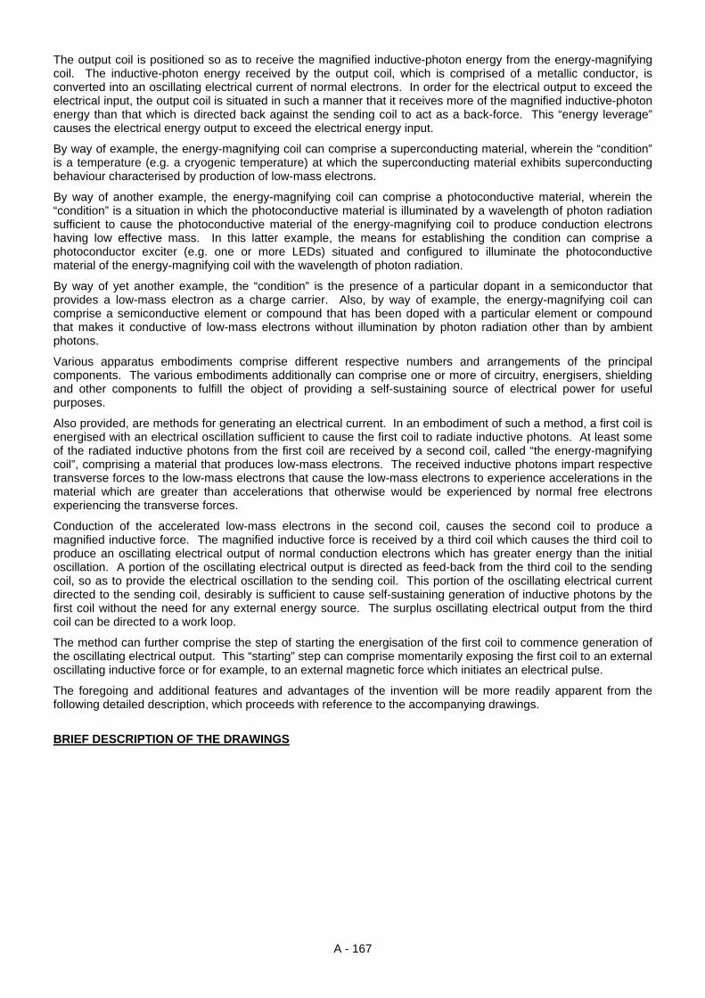
A - 167
The output coil is positioned so as to receive the magnified inductive-photon energy from the energy-magnifying coil. The inductive-photon energy received by the output coil, which is comprised of a metallic conductor, is converted into an oscillating electrical current of normal electrons. In order for the electrical output to exceed the electrical input, the output coil is situated in such a manner that it receives more of the magnified inductive-photon energy than that which is directed back against the sending coil to act as a back-force. This “energy leverage” causes the electrical energy output to exceed the electrical energy input.
By way of example, the energy-magnifying coil can comprise a superconducting material, wherein the “condition” is a temperature (e.g. a cryogenic temperature) at which the superconducting material exhibits superconducting behaviour characterised by production of low-mass electrons.
By way of another example, the energy-magnifying coil can comprise a photoconductive material, wherein the “condition” is a situation in which the photoconductive material is illuminated by a wavelength of photon radiation sufficient to cause the photoconductive material of the energy-magnifying coil to produce conduction electrons having low effective mass. In this latter example, the means for establishing the condition can comprise a photoconductor exciter (e.g. one or more LEDs) situated and configured to illuminate the photoconductive material of the energy-magnifying coil with the wavelength of photon radiation.
By way of yet another example, the “condition” is the presence of a particular dopant in a semiconductor that provides a low-mass electron as a charge carrier. Also, by way of example, the energy-magnifying coil can comprise a semiconductive element or compound that has been doped with a particular element or compound that makes it conductive of low-mass electrons without illumination by photon radiation other than by ambient photons.
Various apparatus embodiments comprise different respective numbers and arrangements of the principal components. The various embodiments additionally can comprise one or more of circuitry, energisers, shielding and other components to fulfill the object of providing a self-sustaining source of electrical power for useful purposes.
Also provided, are methods for generating an electrical current. In an embodiment of such a method, a first coil is energised with an electrical oscillation sufficient to cause the first coil to radiate inductive photons. At least some of the radiated inductive photons from the first coil are received by a second coil, called “the energy-magnifying coil”, comprising a material that produces low-mass electrons. The received inductive photons impart respective transverse forces to the low-mass electrons that cause the low-mass electrons to experience accelerations in the material which are greater than accelerations that otherwise would be experienced by normal free electrons experiencing the transverse forces.
Conduction of the accelerated low-mass electrons in the second coil, causes the second coil to produce a magnified inductive force. The magnified inductive force is received by a third coil which causes the third coil to produce an oscillating electrical output of normal conduction electrons which has greater energy than the initial oscillation. A portion of the oscillating electrical output is directed as feed-back from the third coil to the sending coil, so as to provide the electrical oscillation to the sending coil. This portion of the oscillating electrical current directed to the sending coil, desirably is sufficient to cause self-sustaining generation of inductive photons by the first coil without the need for any external energy source. The surplus oscillating electrical output from the third coil can be directed to a work loop.
The method can further comprise the step of starting the energisation of the first coil to commence generation of the oscillating electrical output. This “starting” step can comprise momentarily exposing the first coil to an external oscillating inductive force or for example, to an external magnetic force which initiates an electrical pulse.
The foregoing and additional features and advantages of the invention will be more readily apparent from the following detailed description, which proceeds with reference to the accompanying drawings.
BRIEF DESCRIPTION OF THE DRAWINGS

A - 168
Fig.1A is a perspective view schematically depicting a sending coil in relationship to an energy-magnifying coil such that inductive photons from the sending coil, propagate to the energy-magnifying coil.
Fig.1B is a schematic end-view of the sending coil and energy-magnifying coil of Fig.1A, further depicting radiation of inductive photons from the sending coil and the respective directions of electron flow in the coils.
Fig.1C is a schematic end-view of the sending coil and energy-magnifying coil of Fig.1A, further depicting the production of inwardly-radiating and outwardly-radiating magnified inductive photons from the energy-magnifying coil.

A - 169
Fig.2A is a perspective view schematically showing an internal output coil, coaxially nested inside the energy-magnifying coil to allow efficient induction of the internal output coil by the energy-magnifying coil, wherein the induction current established in the internal output coil is used to power a load connected across the internal output coil.
Fig.2B is a schematic end-view of the coils shown in Fig.2A, further depicting the greater amount of magnified inductive-photon radiation that is received by the external output coil in comparison to the lesser amount that is directed toward the sending coil to act as a back-force.
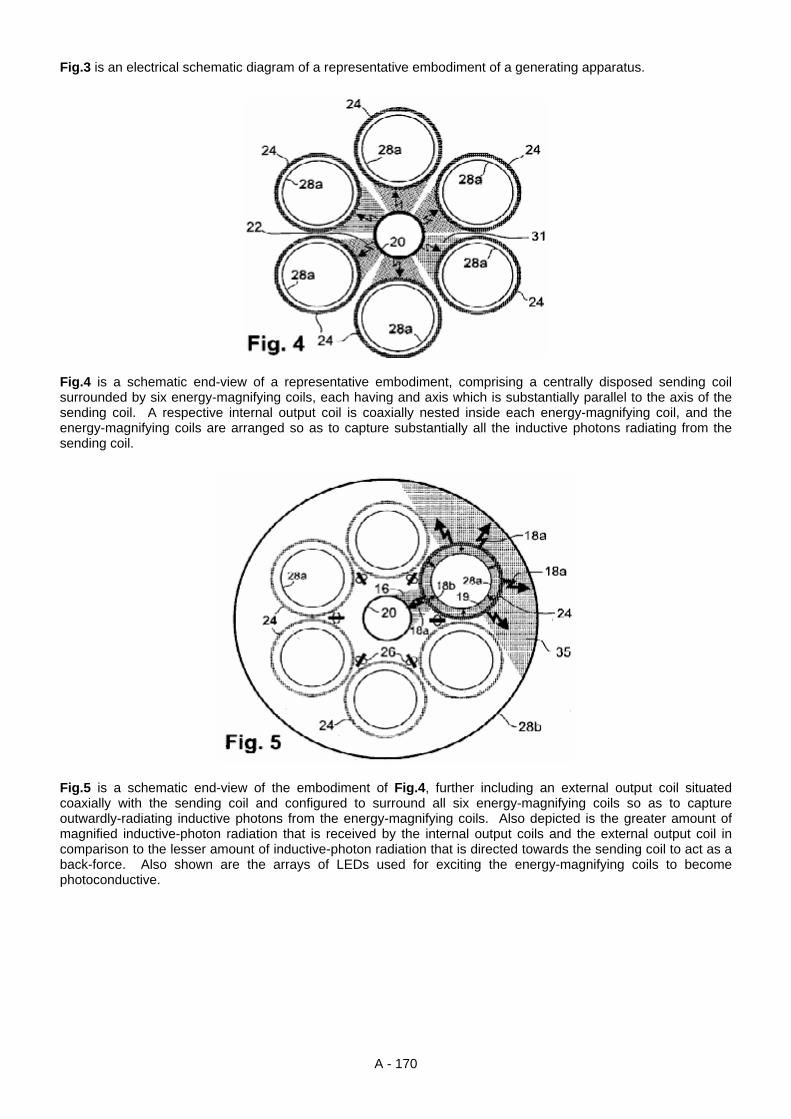
A - 170
Fig.3 is an electrical schematic diagram of a representative embodiment of a generating apparatus.
Fig.4 is a schematic end-view of a representative embodiment, comprising a centrally disposed sending coil surrounded by six energy-magnifying coils, each having and axis which is substantially parallel to the axis of the sending coil. A respective internal output coil is coaxially nested inside each energy-magnifying coil, and the energy-magnifying coils are arranged so as to capture substantially all the inductive photons radiating from the sending coil.
Fig.5 is a schematic end-view of the embodiment of Fig.4, further including an external output coil situated coaxially with the sending coil and configured to surround all six energy-magnifying coils so as to capture outwardly-radiating inductive photons from the energy-magnifying coils. Also depicted is the greater amount of magnified inductive-photon radiation that is received by the internal output coils and the external output coil in comparison to the lesser amount of inductive-photon radiation that is directed towards the sending coil to act as a back-force. Also shown are the arrays of LEDs used for exciting the energy-magnifying coils to become photoconductive.
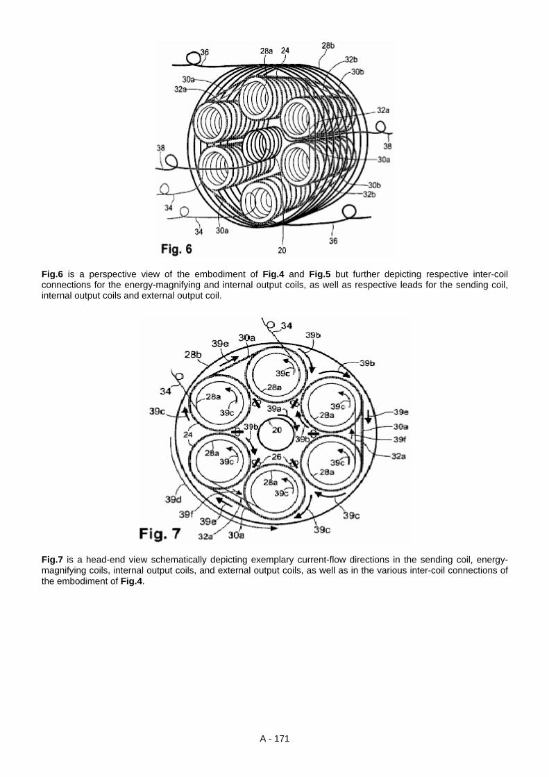
A - 171
Fig.6 is a perspective view of the embodiment of Fig.4 and Fig.5 but further depicting respective inter-coil connections for the energy-magnifying and internal output coils, as well as respective leads for the sending coil, internal output coils and external output coil.
Fig.7 is a head-end view schematically depicting exemplary current-flow directions in the sending coil, energy-magnifying coils, internal output coils, and external output coils, as well as in the various inter-coil connections of the embodiment of Fig.4.

A - 172
Fig.8 is a schematic end-view showing an embodiment of the manner in which inter-coil connections can be made between adjacent energy-magnifying coils.
Fig.9A is a schematic end-view depicting the coil configuration of an embodiment in which a sending coil and an internal output coil are nested inside an energy-magnifying coil, which in turn is nested inside an exterior output coil. A metallic separator, having a substantially parabolic shape, and being situated between the sending coil and the internal output coil, reflects some of the otherwise unused inductive-photon radiation to maximise the effective radiation received by the energy-magnifying coil. Also, the metallic shield prevents the internal output coil from receiving radiation sent from the sending coil.
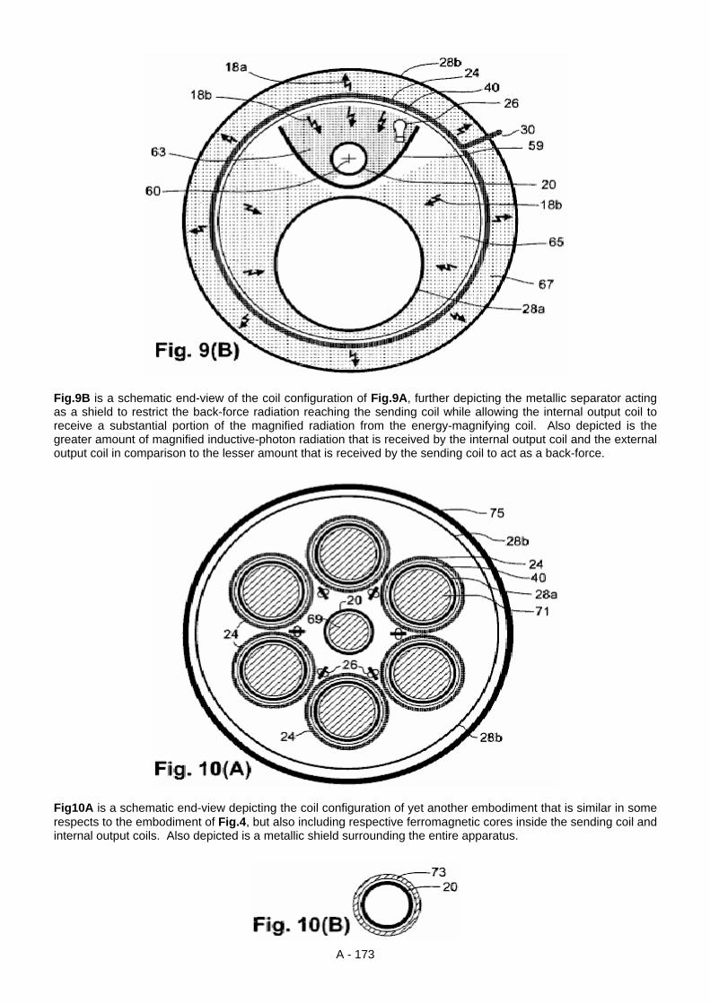
A - 173
Fig.9B is a schematic end-view of the coil configuration of Fig.9A, further depicting the metallic separator acting as a shield to restrict the back-force radiation reaching the sending coil while allowing the internal output coil to receive a substantial portion of the magnified radiation from the energy-magnifying coil. Also depicted is the greater amount of magnified inductive-photon radiation that is received by the internal output coil and the external output coil in comparison to the lesser amount that is received by the sending coil to act as a back-force.
Fig10A is a schematic end-view depicting the coil configuration of yet another embodiment that is similar in some respects to the embodiment of Fig.4, but also including respective ferromagnetic cores inside the sending coil and internal output coils. Also depicted is a metallic shield surrounding the entire apparatus.
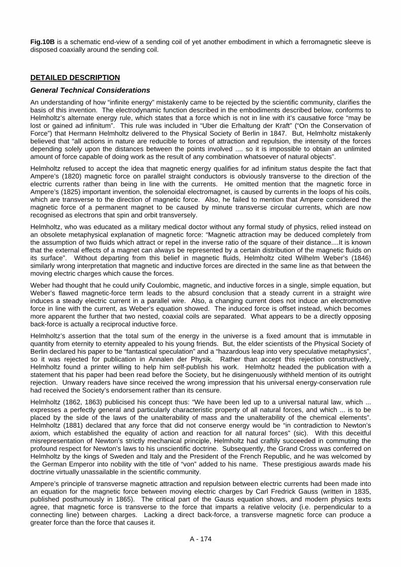
A - 174
Fig.10B is a schematic end-view of a sending coil of yet another embodiment in which a ferromagnetic sleeve is disposed coaxially around the sending coil.
DETAILED DESCRIPTION General Technical Considerations An understanding of how “infinite energy” mistakenly came to be rejected by the scientific community, clarifies the basis of this invention. The electrodynamic function described in the embodiments described below, conforms to Helmholtz’s alternate energy rule, which states that a force which is not in line with it’s causative force “may be lost or gained ad infinitum”. This rule was included in “Uber die Erhaltung der Kraft” (“On the Conservation of Force”) that Hermann Helmholtz delivered to the Physical Society of Berlin in 1847. But, Helmholtz mistakenly believed that “all actions in nature are reducible to forces of attraction and repulsion, the intensity of the forces depending solely upon the distances between the points involved .... so it is impossible to obtain an unlimited amount of force capable of doing work as the result of any combination whatsoever of natural objects”.
Helmholtz refused to accept the idea that magnetic energy qualifies for ad infinitum status despite the fact that Ampere’s (1820) magnetic force on parallel straight conductors is obviously transverse to the direction of the electric currents rather than being in line with the currents. He omitted mention that the magnetic force in Ampere’s (1825) important invention, the solenoidal electromagnet, is caused by currents in the loops of his coils, which are transverse to the direction of magnetic force. Also, he failed to mention that Ampere considered the magnetic force of a permanent magnet to be caused by minute transverse circular currents, which are now recognised as electrons that spin and orbit transversely.
Helmholtz, who was educated as a military medical doctor without any formal study of physics, relied instead on an obsolete metaphysical explanation of magnetic force: “Magnetic attraction may be deduced completely from the assumption of two fluids which attract or repel in the inverse ratio of the square of their distance....It is known that the external effects of a magnet can always be represented by a certain distribution of the magnetic fluids on its surface”. Without departing from this belief in magnetic fluids, Helmholtz cited Wilhelm Weber’s (1846) similarly wrong interpretation that magnetic and inductive forces are directed in the same line as that between the moving electric charges which cause the forces.
Weber had thought that he could unify Coulombic, magnetic, and inductive forces in a single, simple equation, but Weber’s flawed magnetic-force term leads to the absurd conclusion that a steady current in a straight wire induces a steady electric current in a parallel wire. Also, a changing current does not induce an electromotive force in line with the current, as Weber’s equation showed. The induced force is offset instead, which becomes more apparent the further that two nested, coaxial coils are separated. What appears to be a directly opposing back-force is actually a reciprocal inductive force.
Helmholtz’s assertion that the total sum of the energy in the universe is a fixed amount that is immutable in quantity from eternity to eternity appealed to his young friends. But, the elder scientists of the Physical Society of Berlin declared his paper to be “fantastical speculation” and a “hazardous leap into very speculative metaphysics”, so it was rejected for publication in Annalen der Physik. Rather than accept this rejection constructively, Helmholtz found a printer willing to help him self-publish his work. Helmholtz headed the publication with a statement that his paper had been read before the Society, but he disingenuously withheld mention of its outright rejection. Unwary readers have since received the wrong impression that his universal energy-conservation rule had received the Society’s endorsement rather than its censure.
Helmholtz (1862, 1863) publicised his concept thus: “We have been led up to a universal natural law, which ... expresses a perfectly general and particularly characteristic property of all natural forces, and which ... is to be placed by the side of the laws of the unalterability of mass and the unalterability of the chemical elements”. Helmholtz (1881) declared that any force that did not conserve energy would be “in contradiction to Newton’s axiom, which established the equality of action and reaction for all natural forces” (sic). With this deceitful misrepresentation of Newton’s strictly mechanical principle, Helmholtz had craftily succeeded in commuting the profound respect for Newton’s laws to his unscientific doctrine. Subsequently, the Grand Cross was conferred on Helmholtz by the kings of Sweden and Italy and the President of the French Republic, and he was welcomed by the German Emperor into nobility with the title of “von” added to his name. These prestigious awards made his doctrine virtually unassailable in the scientific community.
Ampere’s principle of transverse magnetic attraction and repulsion between electric currents had been made into an equation for the magnetic force between moving electric charges by Carl Fredrick Gauss (written in 1835, published posthumously in 1865). The critical part of the Gauss equation shows, and modern physics texts agree, that magnetic force is transverse to the force that imparts a relative velocity (i.e. perpendicular to a connecting line) between charges. Lacking a direct back-force, a transverse magnetic force can produce a greater force than the force that causes it.

A - 175
The only physicist to recognise in print, the profound significance of the work of Gauss, was James Clerk Maxwell (1873), who stated “(If Gauss’s formula is correct), energy might be generated indefinitely in a finite system by physical means”. Prepossessed with Helmholtz’s “law”, Maxwell chose not to believe Gauss’s transverse magnetic-force equation and accepted Wilhelm Weber’s (1846) erroneous in-line formula instead. Maxwell even admitted knowing of Gauss’s (1845) rebuke of Weber for his mistaken direction of magnetic force as “a complete overthrow of Ampere’s fundamental formula and the adoption of essential a different one”.
In 1893, the critical part of Ampere’s formula for magnetic force, which Weber and Maxwell rejected, and which Helmholtz had replaced with his contrary metaphysical explanation, was proposed for the basis for the international measure of electric current, the Ampere (or amp), to be defined in terms of the transverse magnetic force which the current produces. But Helmholtz’s doctrine had become so impervious to facts that anyone who challenged this “law” faced defamation and ridicule.
The first recognition of unlimited energy came from Sir Joseph Larmor who reported in 1897, “A single ion e, describing an elliptic orbit under an attraction to a fixed centre ... must rapidly lose its energy by radiation ... but in the cases of steady motion, it is just this amount that is needed to maintain the permanency of motion in the aether”. Apparently to mollify critics of his heretical concept, Larmor offered a half-hearted recantation in 1900: “The energy of orbital groups ... would be through time, sensibly dissipated by radiation, so that such groups could not be permanent”.
In 1911, Rutherford found that an atom resembles a small solar system with negative ions moving like planets around a small, positively charged nucleus. These endlessly orbiting electrons were a source of the perpetual radiation that had aptly been described by Larmor, and these orbiting electrons were also Planck’s (1911) “harmonic oscillators” which he used to explain Zero-point Energy (ZPE). ZPE was shown by the fact that helium remains liquid under atmospheric pressure at absolute zero, so that helium must be pressurised to become solid at that temperature. Planck believed that harmonic oscillators derived “dark energy” from the aether to sustain their oscillations, thereby admitting that an infinite source of energy exists. However, he assigned an occult origin to this infinite energy, rather than a conventional source that had not met with Helmholtz’s approval.
Niels Bohr (1924) was bothered by the notion that radiation from an orbiting electron would quickly drain its energy so that the electron should spiral into the nucleus. Whittaker (1951) states, “Bohr and associates abandoned the principle ... that an atom which is emitting or absorbing radiation must be losing or gaining energy. In its place, they introduced the notion or virtual radiation, which was propagated in ... waves but which does not transmit energy or momentum”. Subsequently, the entire scientific community dismissed Larmor radiation as a source of real energy because it failed to conform to Helmholtz’s universally accepted doctrine.
Helmholtz’s constraining idea that the vast amount of light and heat radiating from the many billions of stars in the universe can only come from previously stored energy, has led scientists to concur that fusion of pre-existing hydrogen to helium, supplies nearly all the energy that causes light and heat to radiate from the sun and other starts. If so, then the entire universe will become completely dark after the present hydrogen supply in stars is consumed in about 20 billion years. William A. Fowler (1965) believed that essentially all the hydrogen in the universe “emerged from the first few minutes of the early high-temperature, high-density stage of the expanding Universe, the so-called ‘big bang’ ...” Moreover, the background energy of the universe was thought by some to be “relic” radiation from the “Big Bang”.
To accept the Big Bang idea that all the stars in the universe originated at the same time, it was necessary to disregard the fact that most stars are much younger or much older than the supposed age of the one-time event, which indicates that their energy must have come from a recurring source. The Big Bang is entirely dependent on the idea that the whole universe is expanding, which stemmed from the interpretation that Hubble’s red-shift with distance from the light source, represents a Doppler shift of receding stars and galaxies. This expanding-universe interpretation was shattered by William G. Tifft (1976, 1977), who found that observed red-shifts are not spread randomly and smoothly over a range of values, as would be expected from the Doppler shifts of a vast number of receding stars and galaxies. Instead, the observed red-shifts all fall on evenly spaced, quantised values.
Moreover, Shpenkov and Kreidik (2002) determined that the radiation temperature corresponding to the fundamental period of the orbital electron motion in the hydrogen atom of 2.72890K matches the measured temperature of cosmic background radiation of 2.7250K plus or minus 0.0020K. This represents perpetual zero-level Larmor radiation from interstellar hydrogen atoms dispersed in the universe. So, Helmholtz’s idea that “the energy in the universe is a fixed amount immutable in quantity from eternity to eternity” does not stand up to known facts.
The large aggregate quantity of heat-photons which is generated continually by Larmor radiation can account for the illumination of stars and for the enormous heat and pressure in active galactic centres. Based on the fact that photons exhibit momentum, photons must posses mass, because, as Newton explained, momentum is mass times velocity, which in this case is “c”. Consequently, the creation of photons by induction or by Larmor radiation, also creates new mass. The conditions that Fowler was seeking for hydrogen nucleosynthesis, are apparently being supplied indefinitely in active galaxies and possibly in the sun and other stars above a certain size. This invention utilises a similar unlimited energy source.
A - 176
Another principle that is important to this specification, is that the transfer of energy by electrical induction was found by the Applicant to work in the same manner as the transfer of energy by broadcast and reception of oscillating radio signals. A transverse force is communicated in both cases, the force declines similarly with distance, and the effects of shielding and reflection are identical. Since radio signals are communicated by photons, Applicant considers that inductive force is also communicated by photons. The radiation of newly formed inductive photons results when an accelerated charge experiences a change in direction of acceleration. Inductive radiation occurs when the acceleration of electric charges is reversed, as in Rontgen’s bremsstrahlung, in Hertz’s linear oscillator (plus all other radio-broadcasting antennas), and in coils which carry an alternating current.
In a similar case, when electric charges move in a curving motion due to a continually changing centripetal acceleration, inductive photons are radiated steadily. This includes the radiation from electrons orbiting atomic nuclei (Larmor radiation) and from conduction electrons flowing in a wire coil, whether the current is steady or not. Circularly produced inductive photons induce a circular motion (diamagnetism) in mobile electrons located near the axis of the electron’s circular movement.
In both the reverse-acceleration and centripetal-acceleration cases, inductive photons convey a force to mobile electrons that is transverse to the photon’s propagation path. As Lapp and Andrews (1954) reported, “Low-energy photons produce photoelectrons at right angles to their path ...”. This same right-angle force without a direct back-force, applies as well, to all conduction electrons which are accelerated by low-energy photons. Hence, inductive energy qualifies for exemption from the energy-conservation law by Helmholtz’s same ad infinitum principle which exempts magnetic energy.
The transverse force that inductively produced photons delivered to mobile electrons, is opposite in direction to the simultaneous movement of the primary charge which produces the radiation. This is shown by Faraday’s induced current opposite to the inducing current and by the diamagnetically-induced circular motion which, in a rotational sense, is opposite to the circular electron motion in the coil producing it. An oscillating flow of electrons within a loop of a wire coil, induces a force on the conduction electrons which is in the opposite direction in adjacent loops of the same wire. This results in self-induction.
Important to this specification is the realisation that the energy transmitted by photons is kinetic rather than electromagnetic. Inductively radiated photons of low energy, light rays and X-rays cannot be deflected by and electric or magnetic field due to the photons’ neutral charge. Neither do neutral photons carry an electric or magnetic field with them. Photon radiation is produced by a change in the acceleration of an electric charge, so only in special cases does it have an electrokinetic origin which involves a magnetic force. To honour these facts, Applicant uses the term “electrokinetic spectrum” in place of “electromagnetic spectrum”.
Another principle which is important to this specification is the realisation that, although the charge on the electron has a constant value under all conditions, the mass of an electron is not a fixed, unchanging amount. All free electrons, as in cathode rays, have exactly the same amount of mass at sub-relativistic velocities. This is called “normal” mass and is denoted by me. Free electrons have a unique charge to mass ratio that makes the magnetic force resulting from a sub-relativistic velocity imparted to such an electron, exactly equal to the energy input with “normal” electrons.
Also, when a normal electron is given a sub-relativistic acceleration, the inductive force it produces is equal to the force it receives. The mass of highly conductive electrons of metals is apparently very close to normal, but any very slight inductive-energy gains would be masked by inefficiencies. The ubiquity of free electrons and the conduction electrons of metals has led to the view that electron mass is a never-varying figure that would allow the energy conservation law to apply to magnetic energy and inductive energy.
Accurate determinations of electron mass in solid materials have been made possible by cyclotron resonance, which is also called diamagnetic resonance. The diamagnetic force produced by the steady flow of electrons in a wire coil, induces the mobile electrons of a semiconductor to move in a circular orbit of indefinite radius but at a definite angular frequency. This frequency is only related to the inductive force and the mass of the electron. At the same time, a repulsive magnetic force is developed by the relative velocity between the electron flow in the coil and the conduction electrons, causing the mobile electrons of the semiconductor to move in a helical path away from the coil rather than in planar circles. Only two measurements are needed to determine the mass of such an electron: the cyclotron frequency which resonates with the frequency of the electron’s circular motion, and the strength of the inductive force, which is determined by the current and dimensions of the coil. Since the co-produced magnetic field is related to the same parameters, its measurement serves as a surrogate for inductive force.
Because the measured mass of conduction electrons in semiconductors is less than normal, a complicated explanation has been adopted to defend the constancy of electron mass in order to support Helmholtz’s energy doctrine. An extra force is supposedly received from the vibrational lattice-wave energy of the crystal (in what would have to be an act of self-refrigeration) to make normal-mass electrons move faster than expected around a circular path, thereby giving the appearance that the electron has less mass than normal. In this explanation, the electron is considered to be a smeared-out wave rather than a particle, which is contradicted by the billiard-ball-
A - 177
like recoil of an electron when it is bumped by a quantum of radiation, as described by Arthur Crompton and Samuel Allison (1935).
The fallacy that borrowed energy can provide a boost in velocity to an electron, is more apparent in the case of linear motion. The effective-mass theory considers that the greater linear velocity is caused by a boost given to normal-mass electrons by a “longitudinal wave” imparted by an externally applied force in the same direction as the electron motion. Since this longitudinal wave is also considered to have a source in crystal-lattice vibrations, the effective-mass theory relies on a reversal of entropy in violation of the second Law of Thermodynamics.
No reasonable contribution of direct directional energy can be invoked from any source to impart abnormally great velocity to the conduction electrons in semiconductors. So, the operation of apparatus embodiments described herein, relies on electrons having particle properties and on electrons having less-then-normal inertial mass without invoking any special forces. This is supported by Brennan’s (1999) statement that “the complicated problem of an electron moving within a crystal under the interaction of a periodic but complicated potential, can be reduced to that of a simple free particle, but with a modified mass”. The term “effective” is herein considered redundant in referring to truly inertial mass, but “effective mass” still has relevance in referring to the net movement of orbital vacancies or “holes” in the opposite direction of low-mass electrons.
By F = ma, a low-mass electron receives greater acceleration and greater velocity from a given force than an electron of normal mass. The velocity and kinetic energy imparted to an electrically charged body by a force, are determined by the electric charge without regard to the body’s mass. Having a smaller amount of mass, allows a body to attain a greater velocity with any given force. Hence, the magnetic force produced by the charge at this higher velocity will be greater than it would normally be for that same amount of force. This allows low-mass electrons to produce a magnetic force that is greater than the applied force.
Also, the amount of inductive radiation energy from accelerated electrons is related to an electron’s charge without regard to its mass. The energy of inductive radiation increases with the square of the electron’s acceleration according to Larmor’s (1900) equation, while the acceleration is inversely proportional to the lesser electron mass relative to normal electron mass. Therefore, the greater-than-normal acceleration of low-mass electrons, allows the re-radiation of magnified inductive-photon energy at a magnification factor which is proportional to the inverse square of the electron’s mass, e.g., the inductive-energy magnification factor of cadmium selenide photoelectrons with 0.13 of the normal electron mass is (0.13)2 which is 59 times.
Electrons appear to acquire or shed mass from photons in order to fit the constraints of particular orbits around nuclei, because each orbit dictates a very specific electron mass. In metals, where the conduction electrons seem to move as would a gas, one might think that they would assume the normal mass of free electrons. But the largest mean free path of electrons in the most conductive metals is reportedly about 100 atomic spacings between collisions (Pops, 1997), so the conduction electrons apparently fall back into orbit from time to time and thereby regain their metal-specific mass values.
As conduction electrons pass from one metal type to another, they either lose or gain heat-photons to adjust their mass to different orbital constraints. In a circuit comprising two different metallic conductors placed in series contact with each other, the flow of conduction electrons in one direction will cause the emission of heat-photons at the junction, while an electron flow in the reverse direction causes cooling as the result of ambient heat-photons being absorbed by the conduction electrons at the junction (Peltier cooling effect). When a metal is joined with a semiconductor whose conductive electrons have much lower mass than in metals, much greater heating or cooling occurs at their junction.
John Bardeen (1941) reported that the (effective) mass of superconducting electrons in low-temperature superconductors is only 10-4 as great as the mass of normal electrons. This is demonstrated when superconducting electrons are accelerated to a much higher circular velocity than normal in diamagnetically induced eddy currents, which results in enormous magnetic forces which are capable of levitating heavy magnetic objects. Electrons with 10-4 times normal mass are apparently devoid, (or nearly devoid) of included photon mass, so normal electrons are deduced to posses about 104 times more included photon mass than the bare electron’s own mass.
The means by which photon mass may be incorporated within, or ejected from electrons, can be deduced from known information. Based on the Thompson scattering cross-section, the classical radius of a normal electron is 2 x 10-15 cm. If the electron has uniform charge throughout a sphere of that radius, the peripheral velocity would greatly exceed the velocity of light in order to provide the observed magnetic moment. Dehmelt (1989) determined that the radius of the spinning charge which creates an electron’s magnetism, is approximately 10-20 cm. This apparent incongruity can be explained if the electron is considered to be a hollow shell (which is commensurate with the bare electron’s tiny mass in comparison to the very large radius) and if the negative charge of the shell is not the source of the magnetic moment.
It has long been known that a photon can be split into an negative ion (electron) and a positive ion (positron), each having the same amount of charge but of opposite sign. Electrons and positrons can recombine into electrically neutral photons, so it is apparent that photons are composed of a positive and a negative ion. Two

A - 178
ions spinning around each other could produce the photon’s wave nature. The only size of photon ion that can exist as a separate entity has a charge of exactly plus one or minus one, whereas the ions can have a very much larger or very much smaller charge and mass when combined in photons, as long as the two ions are equal in charge and mass. Combined in a photon, the two ions are apparently attracted together so strongly that their individual volumes are very much smaller than as separate entities.
When a dipole photon enters an electron shell, its negative-ion portion is expected to be forced towards the shell’s centre by Coulombic repulsion, while the photon’s positive ion would be attracted by the negative charge of the shell equally in all directions. The negative photon ions would likely merge into a single body at the electron’s centre, while the positive-ion portion would orbit around the centralised negative ion to retain the photon’s angular momentum. The high peripheral velocity of this orbiting photon mass would enable portions of photon material to spin off and exit the electron shell at the same velocity at which they entered the electron, i.e., the speed of light. The orbiting of the positive photon charge at Dehmelt’s small radius, most likely accounts for the magnetic moment that is observed in electrons of normal mass.
Liberated low-mass conduction electrons within intrinsic semiconductors (which are also photoconductors by their nature) and within doped semiconductors, are mostly protected against acquiring mass from ambient-heat photons by the heat-insulative properties of the semiconductors. In contrast, low-mass electrons injected into heat-conducting metals, rapidly acquire mass from ambient-heat photons by the existence of cryogenic conditions, but they are vulnerable to internal heat-photons created by excessive induction.
Conduction electrons of metals, typically move as a group at drift velocities of less than one millimetre per second, although the velocity of the electrical effects approaches the velocity of light. (Photons are probably involved in the movement of electrical energy in metallic conductors.) In contrast, conductive low-mass electrons can move individually at great velocities in superconductors and semiconductors. Brennan (1999, p. 631) reports the drift velocity of a particular electron moving in a semiconductor, to be one micrometer in about 10 picoseconds, which is equivalent to 100 kilometers per second.
The concentration of the conduction electrons in metals is the same as the number of atoms, whereas in semiconductors, the mobile low-mass electrons which are free to move, can vary greatly with the amount of certain photon radiation received. Since the magnitude of an electric current is a summation of the number of electrons involved, times their respective drift velocities, the current developed by a small ensemble of photoconducting electrons moving at high speed, can exceed the current of a much greater number of conduction electrons moving at a very low speed in a metal.
A general feature of intrinsic semiconductors is that they become photoconductive in proportion to the amount of bombardment by some particular electron-liberating frequency (or band of frequencies) of photon energy, up to some limit. The amount of bombardment by the particular wavelength (or, equivalently, the frequency), increases along with all other photon wavelengths as the ambient temperature rises, that is, as the area under Planck’s black-body radiation curve increases. Consequently, the conductivity of semiconductors continues to increase with temperature, while the conductivity drops to almost zero at low temperature unless superconductivity occurs.
A single high-energy alpha particle can liberate a great number of low-mass electrons in a thin-film semiconductor, as Leimer’s (1915) energy-magnifying experiment appears to show. Leimer’s alpha radiation was situated near the distant end of a suspended antenna wire of unreported length, when he experienced the maximum magnetic energy increase in the coil of the ammeter in the receiver. The low-mass electrons had to have travelled the entire length of the suspended antenna and the connecting line to his receiving apparatus without encountering any trapping holes. Assuming these electrons traversed a distance of 1 to 10 metres in less than one half-cycle of the radio frequency, (that is, less than 4 microseconds at 128 kHz) at which time the direction of the low-mass electron would have been reversed, this would be equivalent to velocities of 25 to 250 km/sec.
A great number of superconducting electrons can be set in motion by inductive photon radiation. In contrast, inductive photon radiation can pass mostly through photoconductors that have low concentrations of mobile, low-mass electrons. Applicant’s interpretation of Leimer’s experiment is that the liberated low-mass electrons of the semiconductor coating of the antenna wire, were not directly accelerated by the inductive photons of the radio signal, but rather were accelerated to high velocities by an oscillating electric field created in the metallic wire by the radio photons.
A review of an experiment performed by File and Mills (1963), shows that the very low mass of superconducting electrons is responsible for causing supercurrents to differ from normal electric currents. A superconducting solenoidal coil (comprising a Nb-25% Zr alloy wire below 4.30 K.) with the terminals spot-welded together to make a continuous conductor, was employed. Extremely slow declines of induced supercurrents were observed, which can be attributed to an enormous increase in the coil’s self-induction. Because a supercurrent approaches its maximum charge asymptotically when discharging, a convenient measure of the coil’s charging or discharging rate is the “time-constant”. The time-constant has the same value for both charging and discharging, and it is defined as (a) the time needed for charging the coil to 63% of the maximum amount of current inducible in the coil by a given diamagnetic force, or (b) the time needed to discharge 63% of the coil’s induced current.
A - 179
In normal conductors, the inductive time-constant is calculated by the inductance of the coil, divided by the resistance of the coil. By use of an empirical equation, the inductance of the coil in its non-superconducting state is calculated to be 0,34 Henry, based on a double-layered solenoid of 384 turns that measured 4 inches (10 cm) diameter and 10 inches (25 cm) long. The resistance of the 0.020 inch (0.51 mm) diameter wire at a temperature of 50 K. (just above Tc) is estimated by using data for Zr alone, to be 4 x 10² ohms. (Resistivity data were not available for Nb or the subject alloy). Under non-superconducting conditions, the time-constant for charging and discharging this coil is thereby calculated to be approximately 8 x 10⁻⁵ sec.
The time it took to charge up a supercurrent in the coil in the experiment was not reported. But, based on the reported 50 re-energisings and magnetic determinations performed in 200 hours, the measured charging time in the superconducting state is computed to be no more than 4 hours on average.
Using Bardeen’s (1941) formula of m is approximately equal to me times 10-4 for the order of magnitude of the low Tc superconducting electron’s mass, and using Larmor’s equation (1900) which relates inductive radiation power to the square of the acceleration of the charge, the inductance of the coil is expected to increase by (104)2 = 108 times in the superconducting state. Thus, the calculated increase in the time-constant of charging up the supercurrent is 8 x 10-5 x 108 which equals 8 x 10³ seconds, or 2.2 hours, which is the same order of magnitude as the maximum actual charging time. The self-induction increased by that amount because the low-mass electrons are accelerated 104 times faster.
In the case of discharging, the time constant of the supercurrent was projected by File and Mills from measured declines observed over periods of 21 and 37 days. The projections of the two 63% declines agreed closely at 4 x 10¹² seconds (= 1.3 x 10⁵ years). Therefore, the time-constant of supercurrent discharge, based on projecting actual measurements, had increased by 5 x 10¹⁶ times over the time-constant for electrons of normal mass.
The driving force during charging, had been the applied inductive force, whereas the driving force during discharging was the supercurrent that had been magnified 108 times. Therefore, during the discharging of the supercurrent, the time-constant is increased again by 108 times, so the calculated total increase in the time-constant of discharge is 108 x 108 = 1016 times greater than the normal time-constant. This calculated value of the non-superconducting time-constant, based solely on the increase of inductive radiation due to extremely low electron mass, compares favourably in magnitude with the actually observed value of 5 x 10¹⁶ times the normal time-constant.
The superconducting coil required no more than four hours to charge up the supercurrent, yet during subsequent discharge, the superconducting coil was projected to radiate inductive photon energy from the centripetal acceleration of the superconducting electrons for 130,000 years before declining by 63%. If this experiment could take place where no energy would needed to sustain critical cryogenic conditions, as in outer space, the lengthy discharge of this energised coil would clearly demonstrate the creation of energy in the form of newly-created photons inductively radiating from the superconducting low-mass electrons that circulate around the coil’s loops. Applicant interprets this as showing that low-mass electrons are capable of inductive-energy-magnification based solely on their mass relative to that of normal electrons.
In the embodiments described below, the magnified inductive energy of low-mass electrons is utilised in coils for electric-energy generation by employing a flow of inductively accelerated photons that alternates in direction. This, in turn, drives low-mass electrons in an oscillating manner, so this forced reversal involves only a single stage of inductive-energy magnification, rather than the two stages (charging and naturally discharging) in the foregoing experiment.
Mode of Operation Inductive photons radiating from an oscillating electric current in a sending conductor (e.g. from a radio-wave broadcasting antenna) convey a force, on conduction electrons in a receiving conductor, that is transverse to the incidence direction of the incident inductive photons on the receiving conductor. As a result, no back-force is transferred directly back to the sending conductor. Applicant has discovered that the action of this transverse force on low-mass electrons in a receiving conductor is analogous to the action of Gauss’s transverse magnetic force on free electrons in a conductor, which is not subject to the kinetics law of conservation of energy. If the receiving conductor has low-mass conduction electrons, then this transverse force would impart greater acceleration to the low-mass electrons than that it would impart to normal free electrons. The resulting greater drift velocities of low-mass electrons than normal free electrons in the receiving conductor, would yield an increased magnitude of inductive force produced by the low-mass electrons in the receiving conductor and hence produce a magnification of the irradiation energy of inductive photons.
The direction of the transverse force imparted by the radiated inductive photons on conduction electrons in the receiving conductor is opposite to the direction of the corresponding electron flow in the sending conductor. This
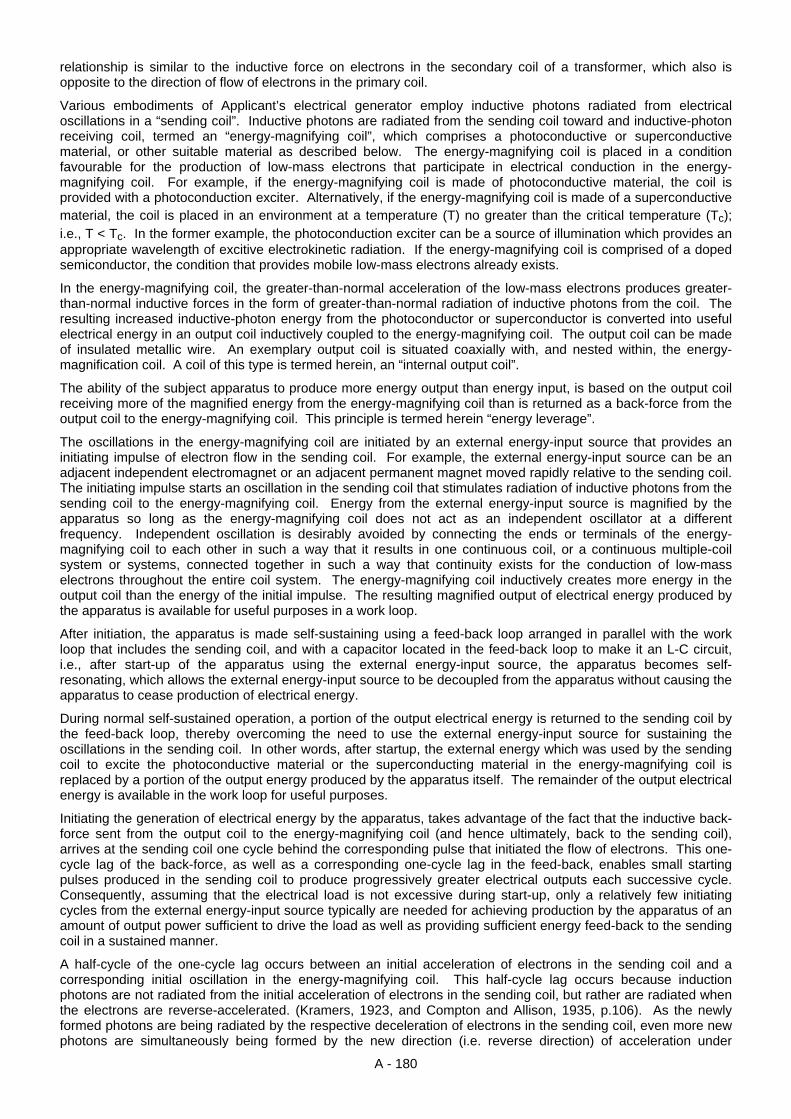
A - 180
relationship is similar to the inductive force on electrons in the secondary coil of a transformer, which also is opposite to the direction of flow of electrons in the primary coil.
Various embodiments of Applicant’s electrical generator employ inductive photons radiated from electrical oscillations in a “sending coil”. Inductive photons are radiated from the sending coil toward and inductive-photon receiving coil, termed an “energy-magnifying coil”, which comprises a photoconductive or superconductive material, or other suitable material as described below. The energy-magnifying coil is placed in a condition favourable for the production of low-mass electrons that participate in electrical conduction in the energy-magnifying coil. For example, if the energy-magnifying coil is made of photoconductive material, the coil is provided with a photoconduction exciter. Alternatively, if the energy-magnifying coil is made of a superconductive material, the coil is placed in an environment at a temperature (T) no greater than the critical temperature (Tc); i.e., T < Tc. In the former example, the photoconduction exciter can be a source of illumination which provides an appropriate wavelength of excitive electrokinetic radiation. If the energy-magnifying coil is comprised of a doped semiconductor, the condition that provides mobile low-mass electrons already exists.
In the energy-magnifying coil, the greater-than-normal acceleration of the low-mass electrons produces greater-than-normal inductive forces in the form of greater-than-normal radiation of inductive photons from the coil. The resulting increased inductive-photon energy from the photoconductor or superconductor is converted into useful electrical energy in an output coil inductively coupled to the energy-magnifying coil. The output coil can be made of insulated metallic wire. An exemplary output coil is situated coaxially with, and nested within, the energy-magnification coil. A coil of this type is termed herein, an “internal output coil”.
The ability of the subject apparatus to produce more energy output than energy input, is based on the output coil receiving more of the magnified energy from the energy-magnifying coil than is returned as a back-force from the output coil to the energy-magnifying coil. This principle is termed herein “energy leverage”.
The oscillations in the energy-magnifying coil are initiated by an external energy-input source that provides an initiating impulse of electron flow in the sending coil. For example, the external energy-input source can be an adjacent independent electromagnet or an adjacent permanent magnet moved rapidly relative to the sending coil. The initiating impulse starts an oscillation in the sending coil that stimulates radiation of inductive photons from the sending coil to the energy-magnifying coil. Energy from the external energy-input source is magnified by the apparatus so long as the energy-magnifying coil does not act as an independent oscillator at a different frequency. Independent oscillation is desirably avoided by connecting the ends or terminals of the energy-magnifying coil to each other in such a way that it results in one continuous coil, or a continuous multiple-coil system or systems, connected together in such a way that continuity exists for the conduction of low-mass electrons throughout the entire coil system. The energy-magnifying coil inductively creates more energy in the output coil than the energy of the initial impulse. The resulting magnified output of electrical energy produced by the apparatus is available for useful purposes in a work loop.
After initiation, the apparatus is made self-sustaining using a feed-back loop arranged in parallel with the work loop that includes the sending coil, and with a capacitor located in the feed-back loop to make it an L-C circuit, i.e., after start-up of the apparatus using the external energy-input source, the apparatus becomes self-resonating, which allows the external energy-input source to be decoupled from the apparatus without causing the apparatus to cease production of electrical energy.
During normal self-sustained operation, a portion of the output electrical energy is returned to the sending coil by the feed-back loop, thereby overcoming the need to use the external energy-input source for sustaining the oscillations in the sending coil. In other words, after startup, the external energy which was used by the sending coil to excite the photoconductive material or the superconducting material in the energy-magnifying coil is replaced by a portion of the output energy produced by the apparatus itself. The remainder of the output electrical energy is available in the work loop for useful purposes.
Initiating the generation of electrical energy by the apparatus, takes advantage of the fact that the inductive back-force sent from the output coil to the energy-magnifying coil (and hence ultimately, back to the sending coil), arrives at the sending coil one cycle behind the corresponding pulse that initiated the flow of electrons. This one-cycle lag of the back-force, as well as a corresponding one-cycle lag in the feed-back, enables small starting pulses produced in the sending coil to produce progressively greater electrical outputs each successive cycle. Consequently, assuming that the electrical load is not excessive during start-up, only a relatively few initiating cycles from the external energy-input source typically are needed for achieving production by the apparatus of an amount of output power sufficient to drive the load as well as providing sufficient energy feed-back to the sending coil in a sustained manner.
A half-cycle of the one-cycle lag occurs between an initial acceleration of electrons in the sending coil and a corresponding initial oscillation in the energy-magnifying coil. This half-cycle lag occurs because induction photons are not radiated from the initial acceleration of electrons in the sending coil, but rather are radiated when the electrons are reverse-accelerated. (Kramers, 1923, and Compton and Allison, 1935, p.106). As the newly formed photons are being radiated by the respective deceleration of electrons in the sending coil, even more new photons are simultaneously being formed by the new direction (i.e. reverse direction) of acceleration under
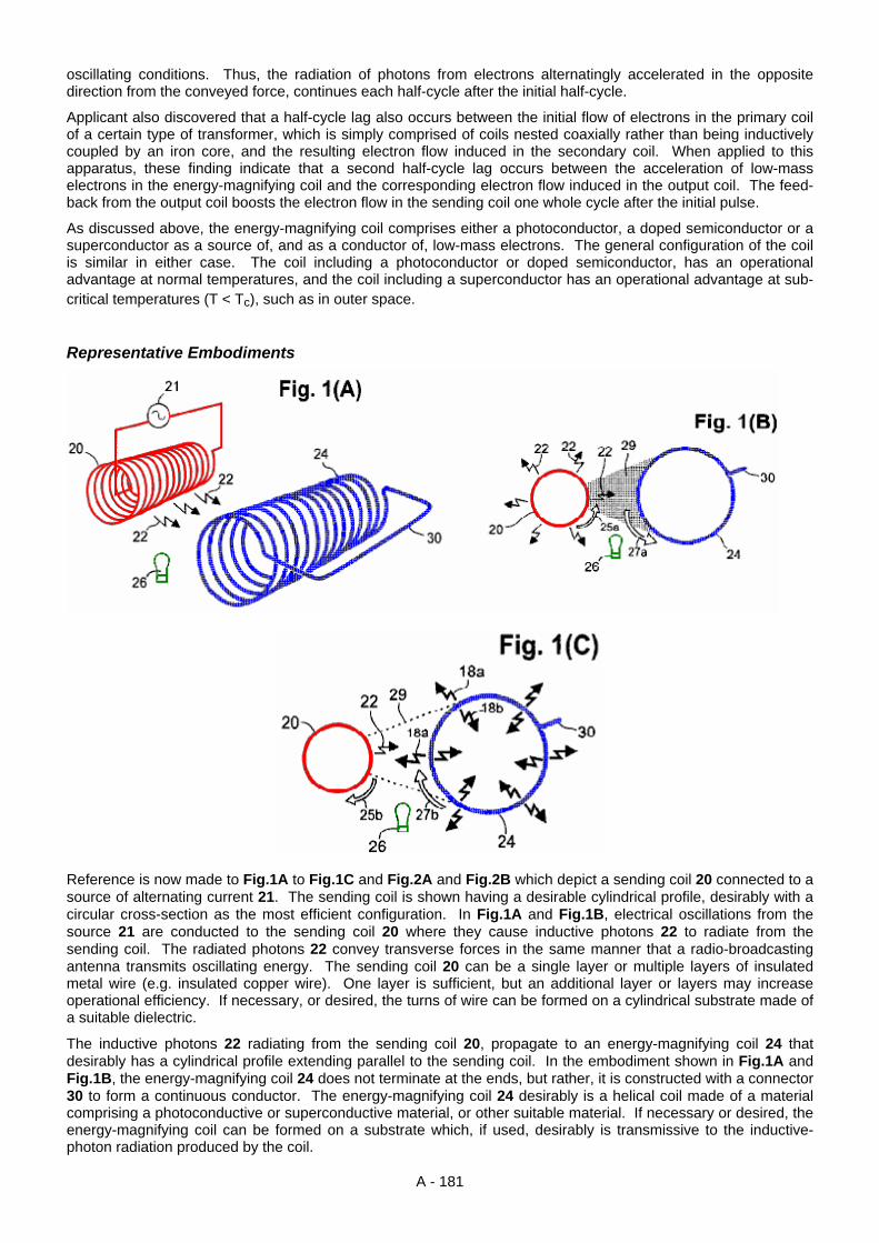
A - 181
oscillating conditions. Thus, the radiation of photons from electrons alternatingly accelerated in the opposite direction from the conveyed force, continues each half-cycle after the initial half-cycle.
Applicant also discovered that a half-cycle lag also occurs between the initial flow of electrons in the primary coil of a certain type of transformer, which is simply comprised of coils nested coaxially rather than being inductively coupled by an iron core, and the resulting electron flow induced in the secondary coil. When applied to this apparatus, these finding indicate that a second half-cycle lag occurs between the acceleration of low-mass electrons in the energy-magnifying coil and the corresponding electron flow induced in the output coil. The feed-back from the output coil boosts the electron flow in the sending coil one whole cycle after the initial pulse.
As discussed above, the energy-magnifying coil comprises either a photoconductor, a doped semiconductor or a superconductor as a source of, and as a conductor of, low-mass electrons. The general configuration of the coil is similar in either case. The coil including a photoconductor or doped semiconductor, has an operational advantage at normal temperatures, and the coil including a superconductor has an operational advantage at sub-critical temperatures (T < Tc), such as in outer space.
Representative Embodiments
Reference is now made to Fig.1A to Fig.1C and Fig.2A and Fig.2B which depict a sending coil 20 connected to a source of alternating current 21. The sending coil is shown having a desirable cylindrical profile, desirably with a circular cross-section as the most efficient configuration. In Fig.1A and Fig.1B, electrical oscillations from the source 21 are conducted to the sending coil 20 where they cause inductive photons 22 to radiate from the sending coil. The radiated photons 22 convey transverse forces in the same manner that a radio-broadcasting antenna transmits oscillating energy. The sending coil 20 can be a single layer or multiple layers of insulated metal wire (e.g. insulated copper wire). One layer is sufficient, but an additional layer or layers may increase operational efficiency. If necessary, or desired, the turns of wire can be formed on a cylindrical substrate made of a suitable dielectric.
The inductive photons 22 radiating from the sending coil 20, propagate to an energy-magnifying coil 24 that desirably has a cylindrical profile extending parallel to the sending coil. In the embodiment shown in Fig.1A and Fig.1B, the energy-magnifying coil 24 does not terminate at the ends, but rather, it is constructed with a connector 30 to form a continuous conductor. The energy-magnifying coil 24 desirably is a helical coil made of a material comprising a photoconductive or superconductive material, or other suitable material. If necessary or desired, the energy-magnifying coil can be formed on a substrate which, if used, desirably is transmissive to the inductive-photon radiation produced by the coil.
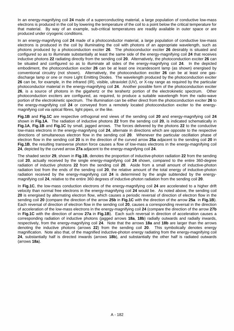
A - 182
In an energy-magnifying coil 24 made of a superconducting material, a large population of conductive low-mass electrons is produced in the coil by lowering the temperature of the coil to a point below the critical temperature for that material. By way of an example, sub-critical temperatures are readily available in outer space or are produced under cryogenic conditions.
In an energy-magnifying coil 24 made of a photoconductor material, a large population of conductive low-mass electrons is produced in the coil by illuminating the coil with photons of an appropriate wavelength, such as photons produced by a photoconduction exciter 26. The photoconductor exciter 26 desirably is situated and configured so as to illuminate substantially at least the same side of the energy-magnifying coil 24 that receives inductive photons 22 radiating directly from the sending coil 20. Alternatively, the photoconduction exciter 26 can be situated and configured so as to illuminate all sides of the energy-magnifying coil 24. In the depicted embodiment, the photoconduction exciter 26 can be at least one incandescent lamp (as shown) energised by conventional circuitry (not shown). Alternatively, the photoconduction exciter 26 can be at least one gas-discharge lamp or one or more Light Emitting Diodes. The wavelength produced by the photoconduction exciter 26 can be, for example, in the infrared (IR), visible, ultraviolet (UV), or X-ray range as required by the particular photoconductor material in the energy-magnifying coil 24. Another possible form of the photoconduction exciter 26, is a source of photons in the gigahertz or the terahertz portion of the electrokinetic spectrum. Other photoconduction exciters are configured, as required, to produce a suitable wavelength from the radio-wave portion of the electrokinetic spectrum. The illumination can be either direct from the photoconduction exciter 26 to the energy-magnifying coil 24 or conveyed from a remotely located photoconduction exciter to the energy-magnifying coil via optical fibres, light pipes, or the like.
Fig.1B and Fig.1C are respective orthogonal end views of the sending coil 20 and energy-magnifying coil 24 shown in Fig.1A. The radiation of inductive photons 22 from the sending coil 20, is indicated schematically in Fig.1A, Fig.1B and Fig.1C by small, jagged arrows. The forces delivered by the photons 22 to the conductive low-mass electrons in the energy-magnifying coil 24, alternate in directions which are opposite to the respective directions of simultaneous electron flow in the sending coil 20. Whenever the particular oscillation phase of electron flow in the sending coil 20 is in the direction of the curved arrow 25a adjacent to the sending coil 20 in Fig.1B, the resulting transverse photon force causes a flow of low-mass electrons in the energy-magnifying coil 24, depicted by the curved arrow 27a adjacent to the energy-magnifying coil 24.
The shaded sector 29, shown in Fig.1B, denotes the proportion of inductive-photon radiation 22 from the sending coil 20, actually received by the single energy-magnifying coil 24 shown, compared to the entire 360-degree radiation of inductive photons 22 from the sending coil 20. Aside from a small amount of inductive-photon radiation lost from the ends of the sending coil 20, the relative amount of the total energy of inductive-photon radiation received by the energy-magnifying coil 24 is determined by the angle subtended by the energy-magnifying coil 24, relative to the entire 360 degrees of inductive-photon radiation from the sending coil 20.
In Fig.1C, the low-mass conduction electrons of the energy-magnifying coil 24 are accelerated to a higher drift velocity than normal free electrons in the energy-magnifying coil 24 would be. As noted above, the sending coil 20 is energised by alternating electron flow, which causes a periodic reversal of direction of electron flow in the sending coil 20 (compare the direction of the arrow 25b in Fig.1C with the direction of the arrow 25a in Fig.1B). Each reversal of direction of electron flow in the sending coil 20, causes a corresponding reversal in the direction of acceleration of the low-mass electrons in the energy-magnifying coil 24 (compare the direction of the arrow 27b in Fig.1C with the direction of arrow 27a in Fig.1B). Each such reversal in direction of acceleration causes a corresponding radiation of inductive photons (jagged arrows 18a, 18b) radially outwards and radially inwards, respectively, from the energy-magnifying coil 24. Note that the arrows 18a and 18b are larger than the arrows denoting the inductive photons (arrows 22) from the sending coil 20. This symbolically denotes energy magnification. Note also that, of the magnified inductive-photon energy radiating from the energy-magnifying coil 24, substantially half is directed inwards (arrows 18b), and substantially the other half is radiated outwards (arrows 18a).

A - 183
Turning now to Fig.2A, the sending coil 20, and the energy-magnifying coil 24, are shown. The energy-magnifying coil 24 in Fig.2A includes an internal output coil 28a, that desirably is situated co-axially inside and is of the same length as the energy-magnifying coil 24. A work loop 48 can be connected to the ends of the internal output coil 28a, thereby forming an electrical circuit in which a load 49 is indicated symbolically as a resistor. The internal output coil 28a and the conductors of the work loop 48, desirably are made of insulated metallic (e.g. copper) wire.
Fig.2B depicts a transverse section of the coils shown in Fig.2A. In Fig.2B, the magnified inductive-photon energy (shaded area 19) produced by the energy-magnifying coil 24 and directed radially inwards towards the internal output coil 28a, induces a corresponding oscillating electron flow in the internal output coil 28a. Thus, the work loop 48 connected across the internal output coil 28a, is provided with greater energy than was received by the energy-magnifying coil 24 from the sending coil 20. The direction of the electron flow (arrow 17) in the internal output coil 28a, is opposite to the direction of flow (arrow 27b) in the energy-magnifying coil 24, which in turn is opposite to the direction of electron flow 25b in the sending coil 20.
In Fig.2B, the annular-shaped shaded area 19 between the energy-magnifying coil 24 and the internal output coil 28a, indicates that substantially all of the internally-directed magnified inductive-photon energy (i.e. approximately half of the total radiation energy) from the energy-magnifying coil 24, is directed to, and captured by, the internal output coil 28a. In contrast, the shaded sector 16 extending from the energy-magnifying coil 24 to the sending coil 20, indicates that a relatively small proportion of the outwardly directed magnified radiation 18a from the energy-magnifying coil 24 is directed to the sending coil 20 where the radiation provides a corresponding back-force. Aside from the small amount of inductive-photon radiation lost from the ends of the energy-magnifying coil 24, the relative amount of the magnified inductive-photon radiation (sector 16) providing the back-force on the sending coil 20, is a function of the angle subtended by the sector 16, compared to the 360-degree radiation from the energy-magnifying coil 24.
The ratio of magnified energy 18b from the energy-magnifying coil 24 and received by the internal output coil 28a, to the magnified energy 18a received as a back-force by the sending coil 20, denotes the energy “leverage” achieved by the subject apparatus. If this ratio is greater than unity, then the energy output from the internal output coil 28a exceeds the energy input to the energy-magnifying coil 24. This energy leverage is key to the self-sustained operation of the apparatus, especially whenever the apparatus is being used to drive a load. In other words, , with a sufficiently large energy-magnification factor achieved by the energy-magnifying coil 24, the electrical energy available in the work loop 48, exceeds the input energy that produces the oscillations in the sending coil 20. The electric power input to the sending coil 20 thereby produces magnified electric power in the internal output coil 28a that can perform useful work in the work loop 48 while self-powering the continued operation of the apparatus.

A - 184
Reference is now made to Fig.3, which schematically depicts aspects of the apparatus 15, responsible for self-generation of electric power by employing a feed-back loop 46. The conductors of the feed-back loop 46 can be made of insulated metallic wire. (In Fig.3, the dotted lines 47a and dotted arrow 47b, indicate that the internal output coil 28a is actually positioned co-axially inside the energy-magnifying coil 24, as described above, but is depicted in the figure as being outside the energy-magnifying coil for ease of illustration). The feed-back loop 46, conducts a portion of the electric power from the internal output coil 28a, back to the sending coil 20. The remaining portion of the electric power from the internal output coil 28a is directed to the work loop 48 where the power is utilised for useful work 51. The relative proportions of output power delivered to the feed-back loop 46 and to the work loop 48, can be varied by adjusting a variable resistor 50.
As noted above, an initial source of electrical energy is used for “starting” the apparatus 15 by initiating an oscillation in the sending coil 20. After starting, under usual operating conditions, the apparatus 15 is self-resonant and no longer requires the input of energy from the initial source. The particular inductance and distributed capacitance of the sending coil 20, plus all other capacitances and inductances in the apparatus, provide a certain corresponding frequency of self-resonating oscillation. In the feed-back loop 46 is a capacitor 77 that makes the apparatus an L-C circuit which oscillates at its own frequency. the frequency can be changed by altering the capacitance or inductance of the apparatus, or both. the capacitor 77 can be a variable capacitor by which the frequency can be adjusted.
As shown in Fig.3, the initial source of oscillating electrical energy can be an impulse from an external electromagnet 52 powered by its own energy source (e.g. a battery 53 as shown, or other DC or AC source). For example, the electromagnet 52 can be placed near the sending coil 20 or other portion of the feed-back loop 46, and energised by a momentary discharge delivered from the battery 53 via a switch 57. The resulting pulse generated in the electromagnet 52, initiates a corresponding electrical pulse in the sending coil 20 that initiates self-sustaining oscillations in the apparatus 15. In another embodiment, the electromagnet 52 can be energised briefly by an AC source (not shown). In yet another embodiment, the initial source can be a permanent magnet which is moved rapidly (either mechanically or manually) near the sending coil 20 or other portion of the feed-back circuitry. In any event, the pulse provided by the initial source initiates electrical oscillations in the sending coil 20 that produce corresponding oscillating inductive-photon radiation 22 from the sending coil 20, as shown schematically in Fig.3 by thin jagged arrows. The inductive-photon radiation 22 from the sending coil 20 causes, in turn, re-radiation of magnified inductive-photon energy 18b from low-mass electrons in the energy-magnifying coil 24, as shown schematically in Fig.3 by thick jagged arrows. Fig.3 depicts a photoconductive energy-magnifying coil 24 which is illuminated by an incandescent photoconduction exciter 26 energised by its own power source 55 (e.g., an externally connected battery as shown).
A sufficiently high energy-magnification factor of the apparatus 15 allows the magnified energy from the energy-magnifying coil 24 to induce greater energy in the internal output coil 28a than the energy of the corresponding initial pulse. A portion of the magnified electrical energy is returned to the sending coil 20 via the feed-back loop 46 to sustain the oscillations.
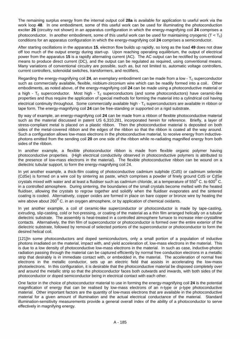
A - 185
The remaining surplus energy from the internal output coil 28a is available for application to useful work via the work loop 48. In one embodiment, some of this useful work can be used for illuminating the photoconduction exciter 26 (circuitry not shown) in an apparatus configuration in which the energy-magnifying coil 24 comprises a photoconductor. In another embodiment, some of this useful work can be used for maintaining cryogenic (T < Tc) conditions for an apparatus configuration in which the energy-magnifying coil 24 comprises a semiconductor.
After starting oscillations in the apparatus 15, electron flow builds up rapidly, so long as the load 49 does not draw off too much of the output energy during start-up. Upon reaching operating equilibrium, the output of electrical power from the apparatus 15 is a rapidly alternating current (AC). The AC output can be rectified by conventional means to produce direct current (DC), and the output can be regulated as required, using conventional means. Many variations of conventional circuitry are possible, such as, but not limited to, automatic voltage controllers, current controllers, solenoidal switches, transformers, and rectifiers,
Regarding the energy-magnifying coil 24, an exemplary embodiment can be made from a low - Tc superconductor such as commercially available, flexible, niobium-zirconium wire which can be readily formed into a coil.. Other embodiments, as noted above, of the energy-magnifying coil 24 can be made using a photoconductive material or a high - Tc superconductor. Most high - Tc superconductors (and some photoconductors) have ceramic-like properties and thus require the application of special methods for forming the material into a cylindrical coil having electrical continuity throughout. Some commercially available high - Tc superconductors are available in ribbon or tape form. The energy-magnifying coil 24 can be free-standing or supported on a rigid substrate.
By way of example, an energy-magnifying coil 24 can be made from a ribbon of flexible photoconductive material such as the material discussed in patent US 6,310,281, incorporated herein for reference. Briefly, a layer of stress-compliant metal is placed on a plastic ribbon. Then the photoconductive material is deposited on both sides of the metal-covered ribbon and the edges of the ribbon so that the ribbon is coated all the way around. Such a configuration allows low-mass electrons in the photoconductive material, to receive energy from inductive-photons emitted from the sending coil 20 on one side of the ribbon while re-radiating magnified energy from both sides of the ribbon.
In another example, a flexible photoconductor ribbon is made from flexible organic polymer having photoconductive properties. (High electrical conductivity observed in photoconductive polymers is attributed to the presence of low-mass electrons in the material). The flexible photoconductive ribbon can be wound on a dielectric tubular support, to form the energy-magnifying coil 24.
In yet another example, a thick-film coating of photoconductive cadmium sulphide (CdS) or cadmium selenide (CdSe) is formed on a wire coil by sintering as paste, which comprises a powder of finely ground CdS or CdSe crystals mixed with water and at least a fluidiser such as cadmium chloride, at a temperature of 5500 C. to 6000 C. in a controlled atmosphere. During sintering, the boundaries of the small crystals become melted with the heated fluidiser, allowing the crystals to regrow together and solidify when the fluidiser evaporates and the sintered coating is cooled. Alternatively, copper oxides are formed in place on bare copper or bronze wire by heating the wire above about 2600 C. in an oxygen atmosphere, or by application of chemical oxidants.
In yet another example, a coil of ceramic-like superconductor or photoconductor is made by tape-casting, extruding, slip-casting, cold or hot-pressing, or coating of the material as a thin film arranged helically on a tubular dielectric substrate. The assembly is heat-treated in a controlled atmosphere furnace to increase inter-crystalline contacts. Alternatively, the thin film of superconductor or photoconductor is formed over the entire exterior of the dielectric substrate, followed by removal of selected portions of the superconductor or photoconductor to form the desired helical coil.
[121]In some photoconductors and doped semiconductors, only a small portion of a population of inductive photons irradiated on the material, impact with, and yield acceleration of, low-mass electrons in the material. This is due to a low density of photoconductive low-mass electrons in the material. In such as case, inductive-photon radiation passing through the material can be captured efficiently by normal free conduction electrons in a metallic strip that desirably is in immediate contact with, or embedded in, the material. The acceleration of normal free electrons in the metallic conductor, sets up an electric field that assists in accelerating the low-mass photoelectrons. In this configuration, it is desirable that the photoconductive material be disposed completely over and around the metallic strip so that the photoconductor faces both outwards and inwards, with both sides of the photoconductor or doped semiconductor being in electrical contact with each other.
One factor in the choice of photoconductor material to use in forming the energy-magnifying coil 24 is the potential magnification of energy that can be realised by low-mass electrons of an n-type or p-type photoconductive material. Other important factors are the quantity of low-mass electrons that are available in the photoconductive material for a given amount of illumination and the actual electrical conductance of the material. Standard illumination-sensitivity measurements provide a general overall index of the ability of a photoconductor to serve effectively in magnifying energy.

A - 186
Cadmium sulphide and cadmium selenide, the most common photoconductive compounds which are available commercially, have calculated magnification factors of 37 and 59, respectively. The peak response wavelength of cadmium sulphide is 515 nanometers (in the green part of the visible spectrum) and of cadmium selenide is 730 nanometers (in the near-infrared part of the spectrum). Cadmium sulphide can be mixed with caesium selenide under certain conditions, so the resulting mixture assumes photoconductive characteristics between those two values. Mixtures can be produced having peak wavelengths which are matched to the wavelengths of commercially available LEDs of many sizes and illumination intensities. Some semiconductors which become photoconductive at a wavelength smaller than the wavelength produced by currently available LEDs can be made conductive of low-mass electrons merely by heating.
Applicant has found that gallium arsenide develops considerably higher conductivity than copper or silver at a temperature of 1000 C. and that the conductive electrons are low-mass. Also, alpha radiation is capable of liberating many low-mass electrons in some semiconductors. A second electron of comparatively low mass may have been liberated from cupric oxide by alpha radiation along with the outer copper electron in Leimer’s (1915) experiments, since the measured energy magnification exceeded the magnification calculated from cyclotron resonance of CuO, which most likely pertains only to the mass of the outer electron.
Dopants can be added to a semiconductor to make it more conductive of low-mass electrons without illumination. Also, the illumination-sensitivity and conductivity of cadmium sulphide are increased by adding small amounts of donor-type dopants such as, but not limited to, sulphides, selenides, tellurides, arsenides, antimonides and phosphides of the Type-IIIa elements: aluminium, gallium, indium and thallium. In this regard, the photoconductors of high-sensitivity photovoltaic cells may comprise as many as five different compounds. The actual mixtures of photoconductive compounds and dopants used in commercially available photovoltaic cells often are trade secrets. But, the sensitivity and conductances of the cells are usually given or are measurable, and these data can be used advantageously in selecting a particular photoconductive compound for use in the apparatus.
Other photoconductive compounds or elements can be employed in energy-magnifying coils. For example, the conduction electrons of silicon have an energy-magnification factor of 15 times. Photoconductors having very high magnification factors include, but are not limited to, gallium arsenide, indium phosphide, gallium antimonide, cadmium-tin arsenide, and cadmium arsenide, which have calculated energy-magnification factors ranging between 200 times and 500 times, and mercury selenide (1100 times), indium arsenide (2000 times), mercury telluride (3400 times) and indium antimonide (5100 times).
The depth of optical transmission largely determines the optimum thickness of photoconductive films for energy-magnifying coils. For example, the highest optical transmission of sintered CdS is reported to be 20 micrometers, but since the average grain size increases (and the average porosity decreases) with an increase in film thickness, the maximum conductivity of a sintered film is at a thickness of 35 micrometers (J. S, Lee et al., 1987).
The metal chosen to be embedded must not react chemically with the photoconductor. For example, aluminium reacts with gallium arsenide (GaAs) in an electrical environment, to change the conductive character of both the GaAs and the aluminium. Gold, platinum, and palladium can serve in many cases because these materials are relatively inert chemically. Gold combines chemically with tellurium, however, so gold is not suitable for embedding in mercury telluride. Cadmium plating over a common metal serves to alleviate the reactivity in cases where cadmium sulphide or cadmium selenide is used as the photoconductor.
The discussion above has been, for ease of explanation, in the context of the apparatus including one energy-magnifying coil 24. However, as discussed, use of a single energy-magnifying coil 24 to capture inductive photons from the sending coil 20, results in loss (by non-capture) of most of the inductive photons from the
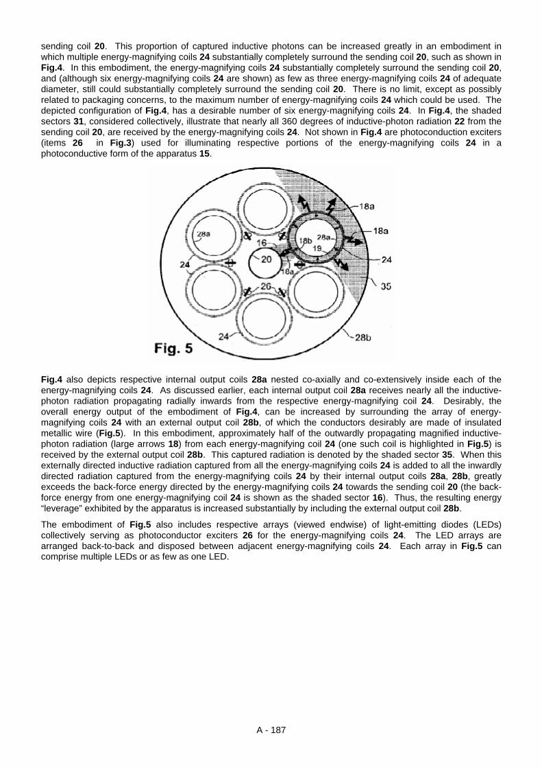
A - 187
sending coil 20. This proportion of captured inductive photons can be increased greatly in an embodiment in which multiple energy-magnifying coils 24 substantially completely surround the sending coil 20, such as shown in Fig.4. In this embodiment, the energy-magnifying coils 24 substantially completely surround the sending coil 20, and (although six energy-magnifying coils 24 are shown) as few as three energy-magnifying coils 24 of adequate diameter, still could substantially completely surround the sending coil 20. There is no limit, except as possibly related to packaging concerns, to the maximum number of energy-magnifying coils 24 which could be used. The depicted configuration of Fig.4, has a desirable number of six energy-magnifying coils 24. In Fig.4, the shaded sectors 31, considered collectively, illustrate that nearly all 360 degrees of inductive-photon radiation 22 from the sending coil 20, are received by the energy-magnifying coils 24. Not shown in Fig.4 are photoconduction exciters (items 26 in Fig.3) used for illuminating respective portions of the energy-magnifying coils 24 in a photoconductive form of the apparatus 15.
Fig.4 also depicts respective internal output coils 28a nested co-axially and co-extensively inside each of the energy-magnifying coils 24. As discussed earlier, each internal output coil 28a receives nearly all the inductive-photon radiation propagating radially inwards from the respective energy-magnifying coil 24. Desirably, the overall energy output of the embodiment of Fig.4, can be increased by surrounding the array of energy-magnifying coils 24 with an external output coil 28b, of which the conductors desirably are made of insulated metallic wire (Fig.5). In this embodiment, approximately half of the outwardly propagating magnified inductive-photon radiation (large arrows 18) from each energy-magnifying coil 24 (one such coil is highlighted in Fig.5) is received by the external output coil 28b. This captured radiation is denoted by the shaded sector 35. When this externally directed inductive radiation captured from all the energy-magnifying coils 24 is added to all the inwardly directed radiation captured from the energy-magnifying coils 24 by their internal output coils 28a, 28b, greatly exceeds the back-force energy directed by the energy-magnifying coils 24 towards the sending coil 20 (the back-force energy from one energy-magnifying coil 24 is shown as the shaded sector 16). Thus, the resulting energy “leverage” exhibited by the apparatus is increased substantially by including the external output coil 28b.
The embodiment of Fig.5 also includes respective arrays (viewed endwise) of light-emitting diodes (LEDs) collectively serving as photoconductor exciters 26 for the energy-magnifying coils 24. The LED arrays are arranged back-to-back and disposed between adjacent energy-magnifying coils 24. Each array in Fig.5 can comprise multiple LEDs or as few as one LED.
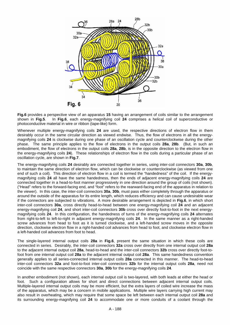
A - 188
Fig.6 provides a perspective view of an apparatus 15 having an arrangement of coils similar to the arrangement shown in Fig.5. In Fig.6, each energy-magnifying coil 24 comprises a helical coil of superconductive or photoconductive material in wire or ribbon (tape-like) form.
Whenever multiple energy-magnifying coils 24 are used, the respective directions of electron flow in them desirably occur in the same circular direction as viewed endwise. Thus, the flow of electrons in all the energy-magnifying coils 24 is clockwise during one phase of an oscillation cycle and counterclockwise during the other phase. The same principle applies to the flow of electrons in the output coils 28a, 28b. (But, in such an embodiment, the flow of electrons in the output coils 28a, 28b, is in the opposite direction to the electron flow in the energy-magnifying coils 24). These relationships of electron flow in the coils during a particular phase of an oscillation cycle, are shown in Fig.7.
The energy-magnifying coils 24 desirably are connected together in series, using inter-coil connectors 30a, 30b, to maintain the same direction of electron flow, which can be clockwise or counterclockwise (as viewed from one end of such a coil). This direction of electron flow in a coil is termed the “handedness” of the coil. If the energy-magnifying coils 24 all have the same handedness, then the ends of adjacent energy-magnifying coils 24 are connected together in a head-to-foot manner progressively in one direction around the group of coils (not shown). (“Head” refers to the forward-facing end, and “foot” refers to the rearward-facing end of the apparatus in relation to the viewer). In this case, the inter-coil connectors 30a, 30b, must pass either completely through the apparatus or around the outside of the apparatus for its entire length, which reduces efficiency and can cause undesirable wear if the connectors are subjected to vibrations. A more desirable arrangement is depicted in Fig.6, in which short inter-coil connectors 30a, cross directly head-to-head between one energy-magnifying coil 24 and an adjacent energy-magnifying coil 24, and short inter-coil connectors 30b cross over directly foot-to-foot in the next energy-magnifying coils 24. In this configuration, the handedness of turns of the energy-magnifying coils 24 alternates from right-to-left to left-to-right in adjacent energy-magnifying coils 24. In the same manner as a right-handed screw advances from head to foot as it is turned clockwise, and a left-handed screw moves in the opposite direction, clockwise electron flow in a right-handed coil advances from head to foot, and clockwise electron flow in a left-handed coil advances from foot to head. The single-layered internal output coils 28a in Fig.6, present the same situation in which these coils are connected in series. Desirably, the inter-coil connectors 32a cross over directly from one internal output coil 28a to the adjacent internal output coil 28a, head-to-head and the inter-coil connectors 32b cross over directly foot-to-foot from one internal output coil 28a to the adjacent internal output coil 28a. This same handedness convention generally applies to all series-connected internal output coils 28a connected in this manner. The head-to-head inter-coil connectors 32a and foot-to-foot inter-coil connectors 32b for the internal output coils 28a, need not coincide with the same respective connectors 30a, 30b for the energy-magnifying coils 24. In another embodiment (not shown), each internal output coil is two-layered, with both leads at either the head or foot. Such a configuration allows for short and direct connections between adjacent internal output coils. Multiple-layered internal output coils may be more efficient, but the extra layers of coiled wire increase the mass of the apparatus, which may be a concern in mobile applications. Multiple wire layers carrying high current may also result in overheating, which may require that some space be left between each internal output coil 28a and its surrounding energy-magnifying coil 24 to accommodate one or more conduits of a coolant through the
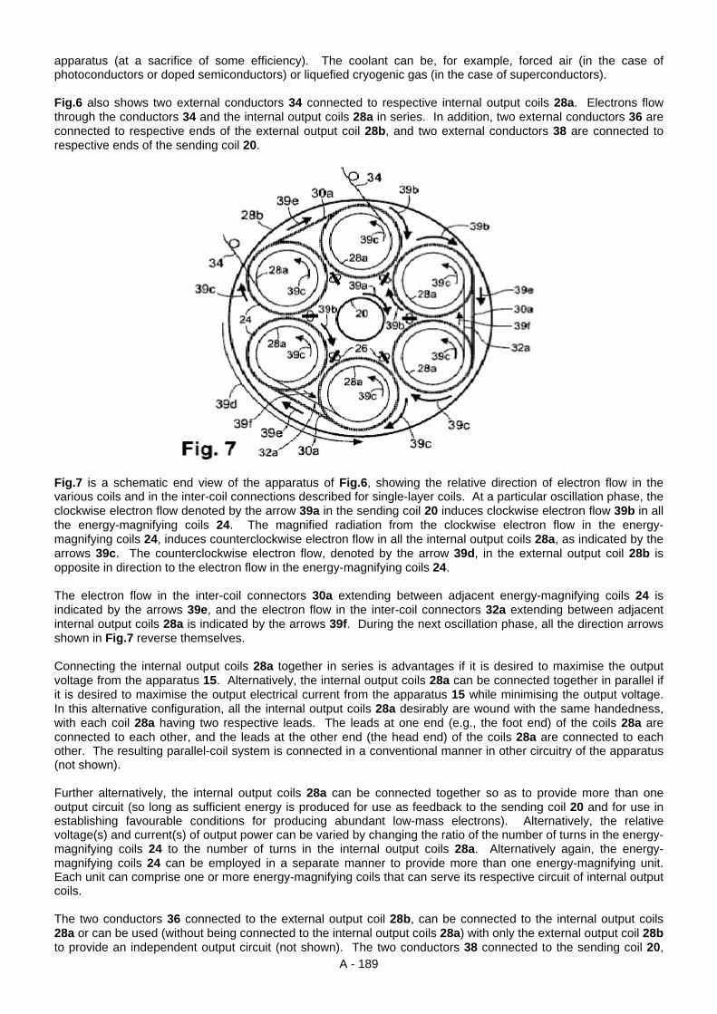
A - 189
apparatus (at a sacrifice of some efficiency). The coolant can be, for example, forced air (in the case of photoconductors or doped semiconductors) or liquefied cryogenic gas (in the case of superconductors). Fig.6 also shows two external conductors 34 connected to respective internal output coils 28a. Electrons flow through the conductors 34 and the internal output coils 28a in series. In addition, two external conductors 36 are connected to respective ends of the external output coil 28b, and two external conductors 38 are connected to respective ends of the sending coil 20.
Fig.7 is a schematic end view of the apparatus of Fig.6, showing the relative direction of electron flow in the various coils and in the inter-coil connections described for single-layer coils. At a particular oscillation phase, the clockwise electron flow denoted by the arrow 39a in the sending coil 20 induces clockwise electron flow 39b in all the energy-magnifying coils 24. The magnified radiation from the clockwise electron flow in the energy-magnifying coils 24, induces counterclockwise electron flow in all the internal output coils 28a, as indicated by the arrows 39c. The counterclockwise electron flow, denoted by the arrow 39d, in the external output coil 28b is opposite in direction to the electron flow in the energy-magnifying coils 24. The electron flow in the inter-coil connectors 30a extending between adjacent energy-magnifying coils 24 is indicated by the arrows 39e, and the electron flow in the inter-coil connectors 32a extending between adjacent internal output coils 28a is indicated by the arrows 39f. During the next oscillation phase, all the direction arrows shown in Fig.7 reverse themselves. Connecting the internal output coils 28a together in series is advantages if it is desired to maximise the output voltage from the apparatus 15. Alternatively, the internal output coils 28a can be connected together in parallel if it is desired to maximise the output electrical current from the apparatus 15 while minimising the output voltage. In this alternative configuration, all the internal output coils 28a desirably are wound with the same handedness, with each coil 28a having two respective leads. The leads at one end (e.g., the foot end) of the coils 28a are connected to each other, and the leads at the other end (the head end) of the coils 28a are connected to each other. The resulting parallel-coil system is connected in a conventional manner in other circuitry of the apparatus (not shown). Further alternatively, the internal output coils 28a can be connected together so as to provide more than one output circuit (so long as sufficient energy is produced for use as feedback to the sending coil 20 and for use in establishing favourable conditions for producing abundant low-mass electrons). Alternatively, the relative voltage(s) and current(s) of output power can be varied by changing the ratio of the number of turns in the energy-magnifying coils 24 to the number of turns in the internal output coils 28a. Alternatively again, the energy-magnifying coils 24 can be employed in a separate manner to provide more than one energy-magnifying unit. Each unit can comprise one or more energy-magnifying coils that can serve its respective circuit of internal output coils. The two conductors 36 connected to the external output coil 28b, can be connected to the internal output coils 28a or can be used (without being connected to the internal output coils 28a) with only the external output coil 28b to provide an independent output circuit (not shown). The two conductors 38 connected to the sending coil 20,
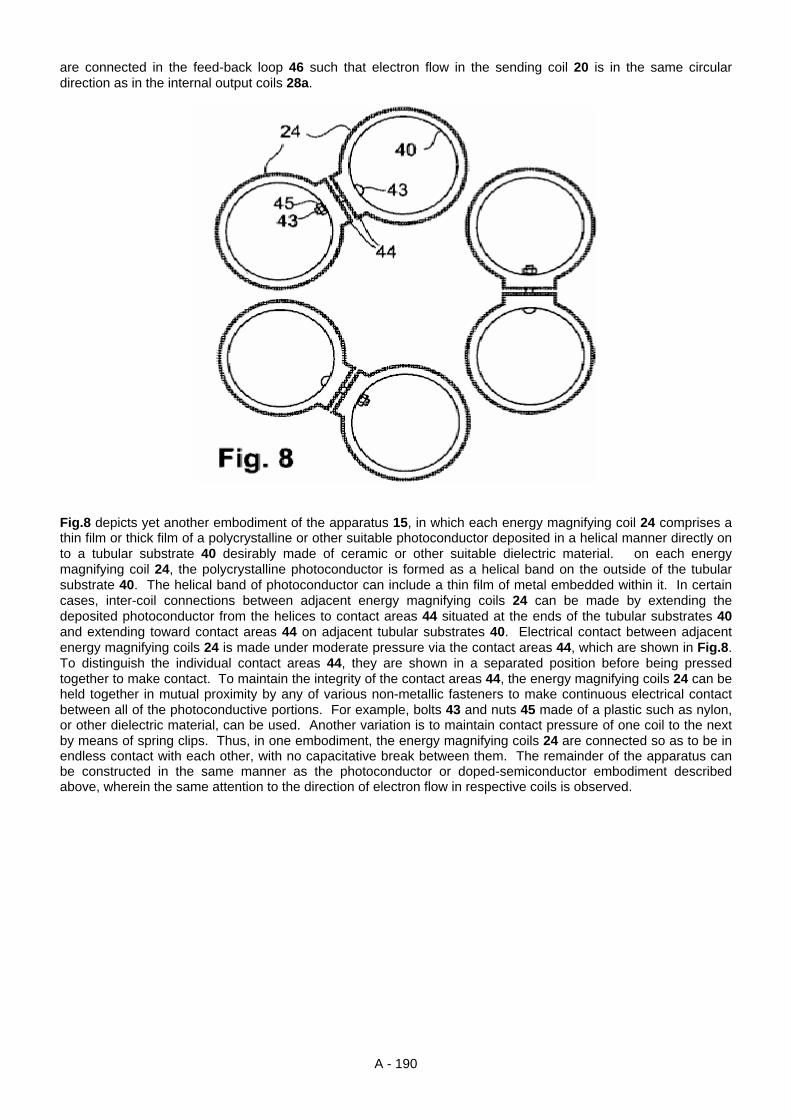
A - 190
are connected in the feed-back loop 46 such that electron flow in the sending coil 20 is in the same circular direction as in the internal output coils 28a.
Fig.8 depicts yet another embodiment of the apparatus 15, in which each energy magnifying coil 24 comprises a thin film or thick film of a polycrystalline or other suitable photoconductor deposited in a helical manner directly on to a tubular substrate 40 desirably made of ceramic or other suitable dielectric material. on each energy magnifying coil 24, the polycrystalline photoconductor is formed as a helical band on the outside of the tubular substrate 40. The helical band of photoconductor can include a thin film of metal embedded within it. In certain cases, inter-coil connections between adjacent energy magnifying coils 24 can be made by extending the deposited photoconductor from the helices to contact areas 44 situated at the ends of the tubular substrates 40 and extending toward contact areas 44 on adjacent tubular substrates 40. Electrical contact between adjacent energy magnifying coils 24 is made under moderate pressure via the contact areas 44, which are shown in Fig.8. To distinguish the individual contact areas 44, they are shown in a separated position before being pressed together to make contact. To maintain the integrity of the contact areas 44, the energy magnifying coils 24 can be held together in mutual proximity by any of various non-metallic fasteners to make continuous electrical contact between all of the photoconductive portions. For example, bolts 43 and nuts 45 made of a plastic such as nylon, or other dielectric material, can be used. Another variation is to maintain contact pressure of one coil to the next by means of spring clips. Thus, in one embodiment, the energy magnifying coils 24 are connected so as to be in endless contact with each other, with no capacitative break between them. The remainder of the apparatus can be constructed in the same manner as the photoconductor or doped-semiconductor embodiment described above, wherein the same attention to the direction of electron flow in respective coils is observed.
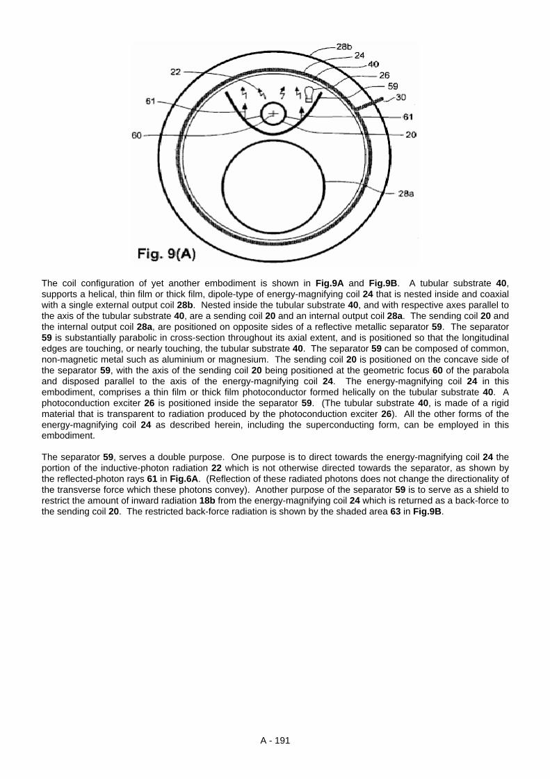
A - 191
The coil configuration of yet another embodiment is shown in Fig.9A and Fig.9B. A tubular substrate 40, supports a helical, thin film or thick film, dipole-type of energy-magnifying coil 24 that is nested inside and coaxial with a single external output coil 28b. Nested inside the tubular substrate 40, and with respective axes parallel to the axis of the tubular substrate 40, are a sending coil 20 and an internal output coil 28a. The sending coil 20 and the internal output coil 28a, are positioned on opposite sides of a reflective metallic separator 59. The separator 59 is substantially parabolic in cross-section throughout its axial extent, and is positioned so that the longitudinal edges are touching, or nearly touching, the tubular substrate 40. The separator 59 can be composed of common, non-magnetic metal such as aluminium or magnesium. The sending coil 20 is positioned on the concave side of the separator 59, with the axis of the sending coil 20 being positioned at the geometric focus 60 of the parabola and disposed parallel to the axis of the energy-magnifying coil 24. The energy-magnifying coil 24 in this embodiment, comprises a thin film or thick film photoconductor formed helically on the tubular substrate 40. A photoconduction exciter 26 is positioned inside the separator 59. (The tubular substrate 40, is made of a rigid material that is transparent to radiation produced by the photoconduction exciter 26). All the other forms of the energy-magnifying coil 24 as described herein, including the superconducting form, can be employed in this embodiment. The separator 59, serves a double purpose. One purpose is to direct towards the energy-magnifying coil 24 the portion of the inductive-photon radiation 22 which is not otherwise directed towards the separator, as shown by the reflected-photon rays 61 in Fig.6A. (Reflection of these radiated photons does not change the directionality of the transverse force which these photons convey). Another purpose of the separator 59 is to serve as a shield to restrict the amount of inward radiation 18b from the energy-magnifying coil 24 which is returned as a back-force to the sending coil 20. The restricted back-force radiation is shown by the shaded area 63 in Fig.9B.
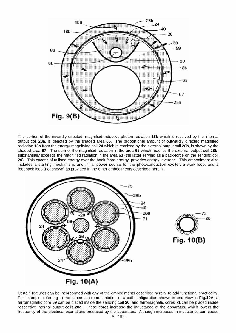
A - 192
The portion of the inwardly directed, magnified inductive-photon radiation 18b which is received by the internal output coil 28a, is denoted by the shaded area 65. The proportional amount of outwardly directed magnified radiation 18a from the energy-magnifying coil 24 which is received by the external output coil 28b, is shown by the shaded area 67. The sum of the magnified radiation in the area 65 which reaches the external output coil 28b, substantially exceeds the magnified radiation in the area 63 (the latter serving as a back-force on the sending coil 20). This excess of utilised energy over the back-force energy, provides energy leverage. This embodiment also includes a starting mechanism, and initial power source for the photoconduction exciter, a work loop, and a feedback loop (not shown) as provided in the other embodiments described herein.
Certain features can be incorporated with any of the embodiments described herein, to add functional practicality. For example, referring to the schematic representation of a coil configuration shown in end view in Fig.10A, a ferromagnetic core 69 can be placed inside the sending coil 20, and ferromagnetic cores 71 can be placed inside respective internal output coils 28a. These cores increase the inductance of the apparatus, which lowers the frequency of the electrical oscillations produced by the apparatus. Although increases in inductance can cause
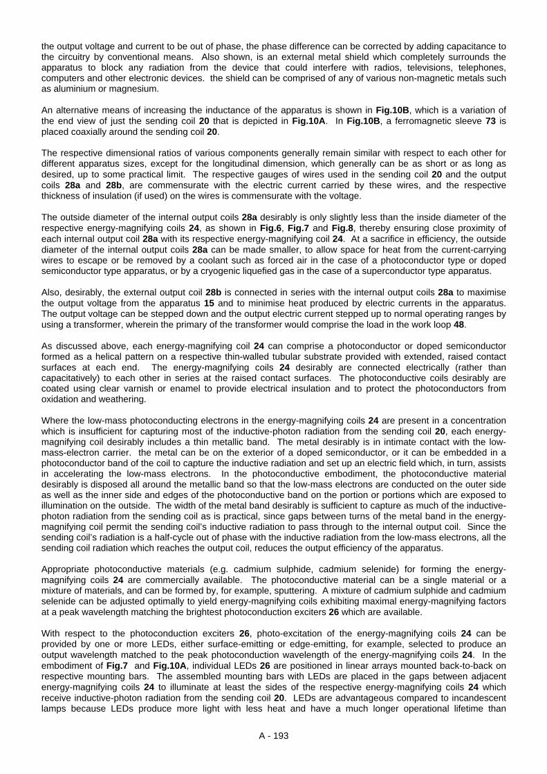
A - 193
the output voltage and current to be out of phase, the phase difference can be corrected by adding capacitance to the circuitry by conventional means. Also shown, is an external metal shield which completely surrounds the apparatus to block any radiation from the device that could interfere with radios, televisions, telephones, computers and other electronic devices. the shield can be comprised of any of various non-magnetic metals such as aluminium or magnesium. An alternative means of increasing the inductance of the apparatus is shown in Fig.10B, which is a variation of the end view of just the sending coil 20 that is depicted in Fig.10A. In Fig.10B, a ferromagnetic sleeve 73 is placed coaxially around the sending coil 20. The respective dimensional ratios of various components generally remain similar with respect to each other for different apparatus sizes, except for the longitudinal dimension, which generally can be as short or as long as desired, up to some practical limit. The respective gauges of wires used in the sending coil 20 and the output coils 28a and 28b, are commensurate with the electric current carried by these wires, and the respective thickness of insulation (if used) on the wires is commensurate with the voltage. The outside diameter of the internal output coils 28a desirably is only slightly less than the inside diameter of the respective energy-magnifying coils 24, as shown in Fig.6, Fig.7 and Fig.8, thereby ensuring close proximity of each internal output coil 28a with its respective energy-magnifying coil 24. At a sacrifice in efficiency, the outside diameter of the internal output coils 28a can be made smaller, to allow space for heat from the current-carrying wires to escape or be removed by a coolant such as forced air in the case of a photoconductor type or doped semiconductor type apparatus, or by a cryogenic liquefied gas in the case of a superconductor type apparatus. Also, desirably, the external output coil 28b is connected in series with the internal output coils 28a to maximise the output voltage from the apparatus 15 and to minimise heat produced by electric currents in the apparatus. The output voltage can be stepped down and the output electric current stepped up to normal operating ranges by using a transformer, wherein the primary of the transformer would comprise the load in the work loop 48. As discussed above, each energy-magnifying coil 24 can comprise a photoconductor or doped semiconductor formed as a helical pattern on a respective thin-walled tubular substrate provided with extended, raised contact surfaces at each end. The energy-magnifying coils 24 desirably are connected electrically (rather than capacitatively) to each other in series at the raised contact surfaces. The photoconductive coils desirably are coated using clear varnish or enamel to provide electrical insulation and to protect the photoconductors from oxidation and weathering. Where the low-mass photoconducting electrons in the energy-magnifying coils 24 are present in a concentration which is insufficient for capturing most of the inductive-photon radiation from the sending coil 20, each energy-magnifying coil desirably includes a thin metallic band. The metal desirably is in intimate contact with the low-mass-electron carrier. the metal can be on the exterior of a doped semiconductor, or it can be embedded in a photoconductor band of the coil to capture the inductive radiation and set up an electric field which, in turn, assists in accelerating the low-mass electrons. In the photoconductive embodiment, the photoconductive material desirably is disposed all around the metallic band so that the low-mass electrons are conducted on the outer side as well as the inner side and edges of the photoconductive band on the portion or portions which are exposed to illumination on the outside. The width of the metal band desirably is sufficient to capture as much of the inductive-photon radiation from the sending coil as is practical, since gaps between turns of the metal band in the energy-magnifying coil permit the sending coil’s inductive radiation to pass through to the internal output coil. Since the sending coil’s radiation is a half-cycle out of phase with the inductive radiation from the low-mass electrons, all the sending coil radiation which reaches the output coil, reduces the output efficiency of the apparatus. Appropriate photoconductive materials (e.g. cadmium sulphide, cadmium selenide) for forming the energy-magnifying coils 24 are commercially available. The photoconductive material can be a single material or a mixture of materials, and can be formed by, for example, sputtering. A mixture of cadmium sulphide and cadmium selenide can be adjusted optimally to yield energy-magnifying coils exhibiting maximal energy-magnifying factors at a peak wavelength matching the brightest photoconduction exciters 26 which are available. With respect to the photoconduction exciters 26, photo-excitation of the energy-magnifying coils 24 can be provided by one or more LEDs, either surface-emitting or edge-emitting, for example, selected to produce an output wavelength matched to the peak photoconduction wavelength of the energy-magnifying coils 24. In the embodiment of Fig.7 and Fig.10A, individual LEDs 26 are positioned in linear arrays mounted back-to-back on respective mounting bars. The assembled mounting bars with LEDs are placed in the gaps between adjacent energy-magnifying coils 24 to illuminate at least the sides of the respective energy-magnifying coils 24 which receive inductive-photon radiation from the sending coil 20. LEDs are advantageous compared to incandescent lamps because LEDs produce more light with less heat and have a much longer operational lifetime than

A - 194
incandescent lamps. LEDs are also preferred because of their small size which facilitates fitting a large number of them into the relatively small space between adjacent energy-magnifying coils 24. Whereas the invention has been described in connection with several representative embodiments, the invention is not limited to those embodiments. On the contrary, the invention is intended to encompass all modifications, alternatives and equivalents as may be included within the spirit and scope of the invention, as defined by the appended claims. References Cited in the Text Helmholtz, H., 1847, Uber die Erhaltung der Kraft, G.A.Reimer, Berlin. On the Conservation of Force, English translation with Appendices of 1881, Wesleyan university Press, Middletown Conn., 1971. Leimer, E., 1915, “Uber Radiumantennen”, Elektrotechnische Zeitschrift, Heft 8, Feb. 25, 1915. English translation: “On Radium Antannae” The Electrician, Apr. 21 1916, and “Radium and Aerials” Scientific American, Supplement No. 2127, Oct. 7, 1916. Anon, 1919a, “Youthful Seattle Inventor and his Invention” (photos and captions), Seattle Post-Intelligencer, Dec. 17, 1919. Anon., 1919b, “Youth’s Revolutionary invention is Backed by Professor - Hubbard’s New Energy No Fake, Says Seattle College Man”, Seattle Post-Intelligencer, Dec. 17, 1919, Anon. 1920a, “Hubbard Coil Runs Boat on Portage Bay Ten Knots an Hour, Auto Test Next”, Seattle Post-Intelligencer, Jul. 29, 1920. Anon., 1920b, “Drives Boat with New Electric Generator” (photos and captions), Seattle Post-Intelligencer, Jul. 29, 1920. Anon., 1928a, “Noted Flyers Try Out New Motor at Selfridge Field” (photo), Detroit Free Press, Fen. 25, 1928. Anon., 1928b, “Fuelless Motor Shown; Gets Current From Air”, Detroit Free Press, Feb. 25, 1928. White, H. C., 1928c, “Lindbergh Tries Motor Earth Runs”, Detroit Free Press, Feb. 25, 1928. Anon., 1928d, “Fuelless Motor Impresses Experts”, New York Times, Feb. 26, 1928. Anon., 1928e, “No-Fuel Motor Finds Backers”, Detroit News, Feb. 26, 1928. Anon., 1928f, “Fuelless Motor Is A Generator”, New York Times, Feb. 27, 1928. Anon., 1928g, “Fuelless Motor Ends 2-year Task”, Seattle Post-Intelligencer, Feb. 27, 1928. Bermann, R. B., 1928 h, “Hubbard Believes Mystery Motor Based Upon His Own Invention”, Seattle Post-Intelligencer, Feb. 27, 1928. Ampere, A. M., 1820, “Memoire”, Annales de Chimie et de Physique. Ampere, A. M., 1825, “Memoire”, Annales de Chimie et de Physique. Weber, W., 1846, Elektrodynamische Maassbestimmungen, Weidmann’sche Buchhandlung, Leipzig. Gauss, C. F., 1835, unpublished notes originally published posthumously in 1865 as “Grundgesetz Fur Alle Wechselwirkungen Galvanisvcher Strome” in Werke, Vol. 5, pp. 616-620; the correspondence from Gauss to Wilhelm Weber (1845) is on pp. 627-629. Maxwell, J. C., 1873, A Treatise on Electricity and Magnetism, Clarendon Press, Oxford. Larmor, J., 1897, “On the Theory of Magnetic Influence of Spectra; and on the Radiation From Moving Ions”, Phil. Mag LXIII:503-512. Larmor, J., 1900, Aether and Matter, Cambridge University Press. Rutherford, E., 1911, Phil. Mag. XXI:669.
A - 195
Planck, M., 1911, Verh. D. Deutsch. Phys. Ges. XIII:138 Bohr, N., Kramers, H. A., and Slater, J. C., 1924, Phil. Mag. XLVII:785 Whittaker, E., 1951, A History of the Theories of Aether and Electricity, Thos. Nelson & Sons, London; reprinted by Dover, New York, 1989. Shpenkov, G. P., and Kreidik, L. G., “Microwave Background Radiation of Hydrogen Atoms”, Revista Ceencias Exastas e Naturais 4, n.1, pp. 9-18, January/June 2002. Fowler, W. A., 1983, “Experimental and Theoretical Nuclear Astrophysics; the Quest for the Origin of the Elements”, Nobel Lecture, Dec. 8, 1983. Tifft, W. G., 1976, “Discrete States of Redshift and Galaxy Dynamics I", Astrophysical Journal 206:38-56. Tifft, W. G., 1977, “Discrete States of Redshift and Galaxy Dynamics I I: Systems of Galaxies”, Astrophysical Journal 211:31-46; and “Discrete States of Redshift and Galaxy Dynamics I I I: Abnormal Galaxies”, Astrophysical Journal 211:377-391. Compton, A. H. and Allison, S. K., 1935, “X-Rays in Theory and Experiment” 2nd Ed., Van Nostrand, New York. Pops, H., 1997, “The Metallurgy of Copper Wire”, Innovations, Dec. 1997 (Copper Development Assoc.). Lapp, R. E. and Andrews, H. L., 1954, Nuclear Radiation Physics, Prentice-Hall, Englewood Cliffs, N.J. Bardeen, J., 1942, “Theory of Superconductivity” (abstr.), Phys. Rev. 59:298. Dehmelt, H. G., 1989, “Experiments with an Isolated Subatomic Particle at Rest”, Nobel Lecture, Dec. 8, 1989. File, J. and Mills, R. G., 1963, “Observation of Persistent Current in a Superconducting Solenoid”, Phys. Rev. Lett. 10(3), Feb. 1, 1963.
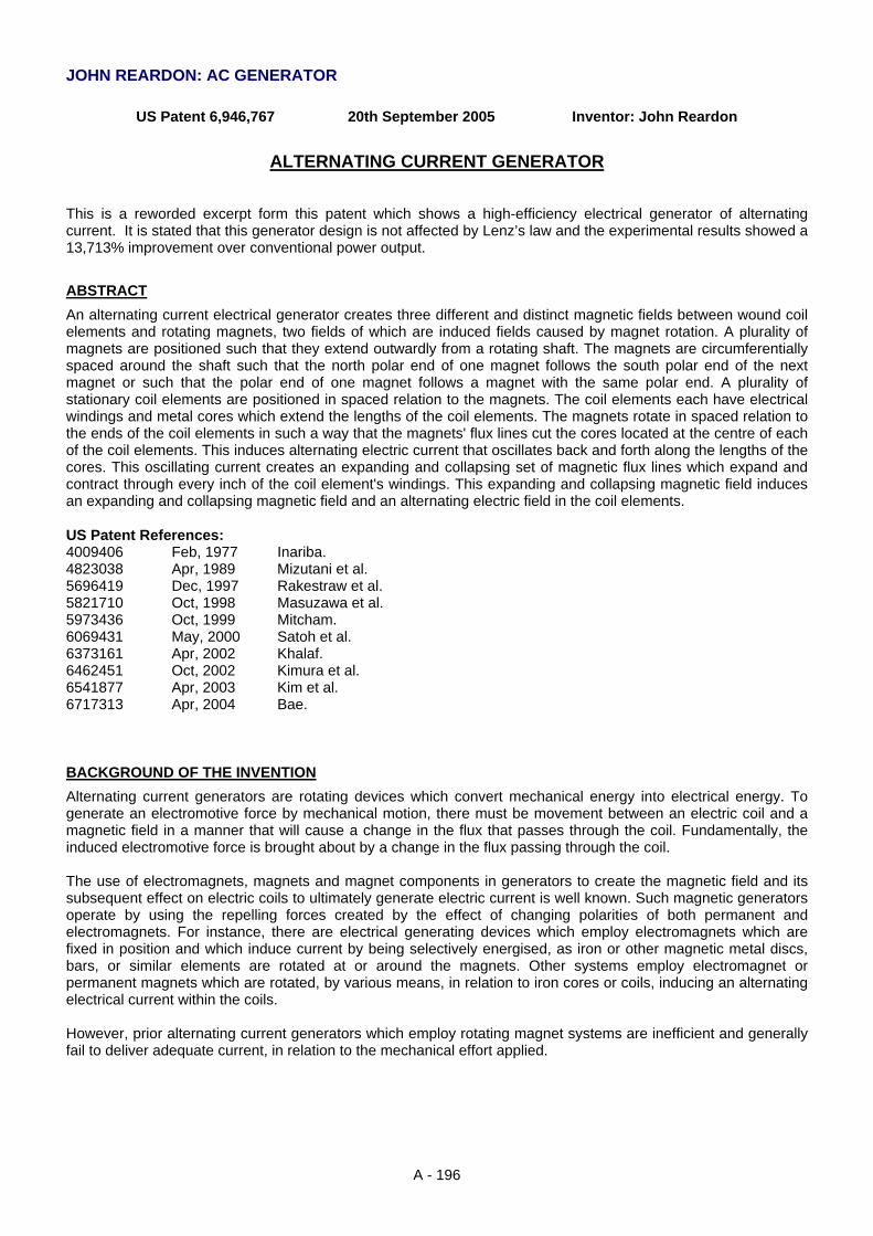
A - 196
JOHN REARDON: AC GENERATOR
US Patent 6,946,767 20th September 2005 Inventor: John Reardon
ALTERNATING CURRENT GENERATOR
This is a reworded excerpt form this patent which shows a high-efficiency electrical generator of alternating current. It is stated that this generator design is not affected by Lenz’s law and the experimental results showed a 13,713% improvement over conventional power output.
ABSTRACT An alternating current electrical generator creates three different and distinct magnetic fields between wound coil elements and rotating magnets, two fields of which are induced fields caused by magnet rotation. A plurality of magnets are positioned such that they extend outwardly from a rotating shaft. The magnets are circumferentially spaced around the shaft such that the north polar end of one magnet follows the south polar end of the next magnet or such that the polar end of one magnet follows a magnet with the same polar end. A plurality of stationary coil elements are positioned in spaced relation to the magnets. The coil elements each have electrical windings and metal cores which extend the lengths of the coil elements. The magnets rotate in spaced relation to the ends of the coil elements in such a way that the magnets' flux lines cut the cores located at the centre of each of the coil elements. This induces alternating electric current that oscillates back and forth along the lengths of the cores. This oscillating current creates an expanding and collapsing set of magnetic flux lines which expand and contract through every inch of the coil element's windings. This expanding and collapsing magnetic field induces an expanding and collapsing magnetic field and an alternating electric field in the coil elements. US Patent References: 4009406 Feb, 1977 Inariba. 4823038 Apr, 1989 Mizutani et al. 5696419 Dec, 1997 Rakestraw et al. 5821710 Oct, 1998 Masuzawa et al. 5973436 Oct, 1999 Mitcham. 6069431 May, 2000 Satoh et al. 6373161 Apr, 2002 Khalaf. 6462451 Oct, 2002 Kimura et al. 6541877 Apr, 2003 Kim et al. 6717313 Apr, 2004 Bae. BACKGROUND OF THE INVENTION Alternating current generators are rotating devices which convert mechanical energy into electrical energy. To generate an electromotive force by mechanical motion, there must be movement between an electric coil and a magnetic field in a manner that will cause a change in the flux that passes through the coil. Fundamentally, the induced electromotive force is brought about by a change in the flux passing through the coil. The use of electromagnets, magnets and magnet components in generators to create the magnetic field and its subsequent effect on electric coils to ultimately generate electric current is well known. Such magnetic generators operate by using the repelling forces created by the effect of changing polarities of both permanent and electromagnets. For instance, there are electrical generating devices which employ electromagnets which are fixed in position and which induce current by being selectively energised, as iron or other magnetic metal discs, bars, or similar elements are rotated at or around the magnets. Other systems employ electromagnet or permanent magnets which are rotated, by various means, in relation to iron cores or coils, inducing an alternating electrical current within the coils. However, prior alternating current generators which employ rotating magnet systems are inefficient and generally fail to deliver adequate current, in relation to the mechanical effort applied.
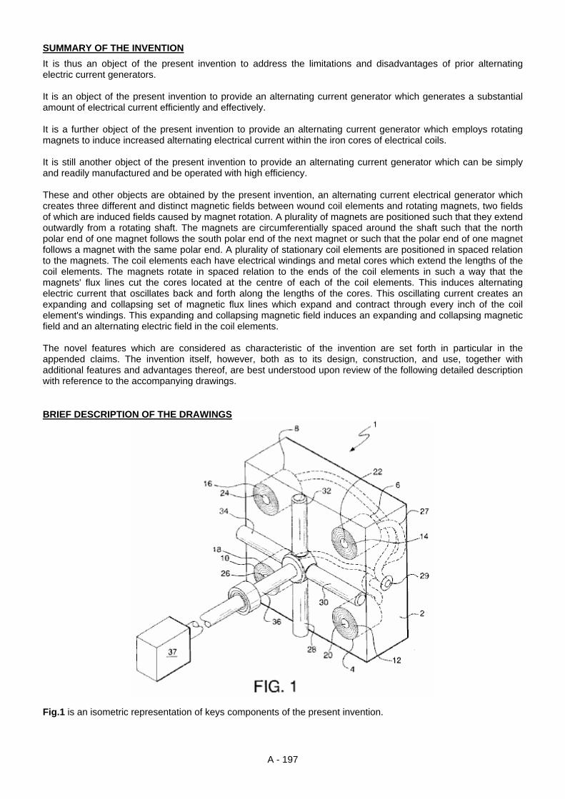
A - 197
SUMMARY OF THE INVENTION It is thus an object of the present invention to address the limitations and disadvantages of prior alternating electric current generators. It is an object of the present invention to provide an alternating current generator which generates a substantial amount of electrical current efficiently and effectively. It is a further object of the present invention to provide an alternating current generator which employs rotating magnets to induce increased alternating electrical current within the iron cores of electrical coils. It is still another object of the present invention to provide an alternating current generator which can be simply and readily manufactured and be operated with high efficiency. These and other objects are obtained by the present invention, an alternating current electrical generator which creates three different and distinct magnetic fields between wound coil elements and rotating magnets, two fields of which are induced fields caused by magnet rotation. A plurality of magnets are positioned such that they extend outwardly from a rotating shaft. The magnets are circumferentially spaced around the shaft such that the north polar end of one magnet follows the south polar end of the next magnet or such that the polar end of one magnet follows a magnet with the same polar end. A plurality of stationary coil elements are positioned in spaced relation to the magnets. The coil elements each have electrical windings and metal cores which extend the lengths of the coil elements. The magnets rotate in spaced relation to the ends of the coil elements in such a way that the magnets' flux lines cut the cores located at the centre of each of the coil elements. This induces alternating electric current that oscillates back and forth along the lengths of the cores. This oscillating current creates an expanding and collapsing set of magnetic flux lines which expand and contract through every inch of the coil element's windings. This expanding and collapsing magnetic field induces an expanding and collapsing magnetic field and an alternating electric field in the coil elements. The novel features which are considered as characteristic of the invention are set forth in particular in the appended claims. The invention itself, however, both as to its design, construction, and use, together with additional features and advantages thereof, are best understood upon review of the following detailed description with reference to the accompanying drawings. BRIEF DESCRIPTION OF THE DRAWINGS
Fig.1 is an isometric representation of keys components of the present invention.
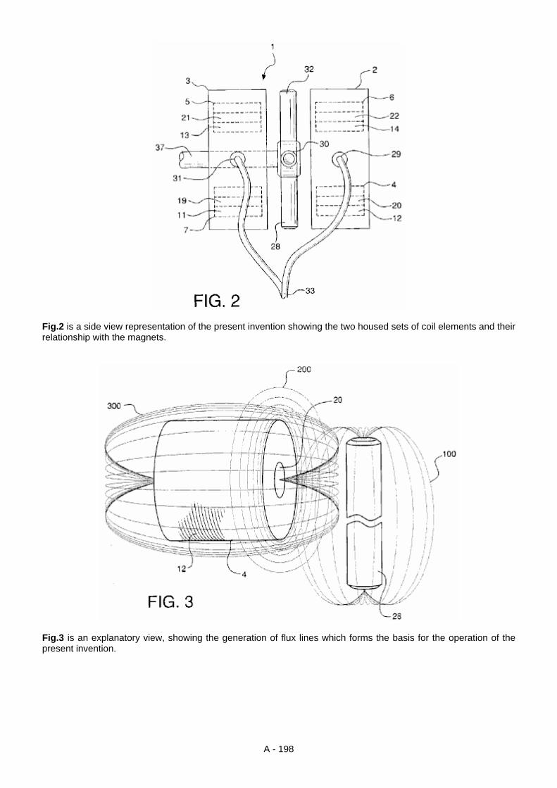
A - 198
Fig.2 is a side view representation of the present invention showing the two housed sets of coil elements and their relationship with the magnets.
Fig.3 is an explanatory view, showing the generation of flux lines which forms the basis for the operation of the present invention.
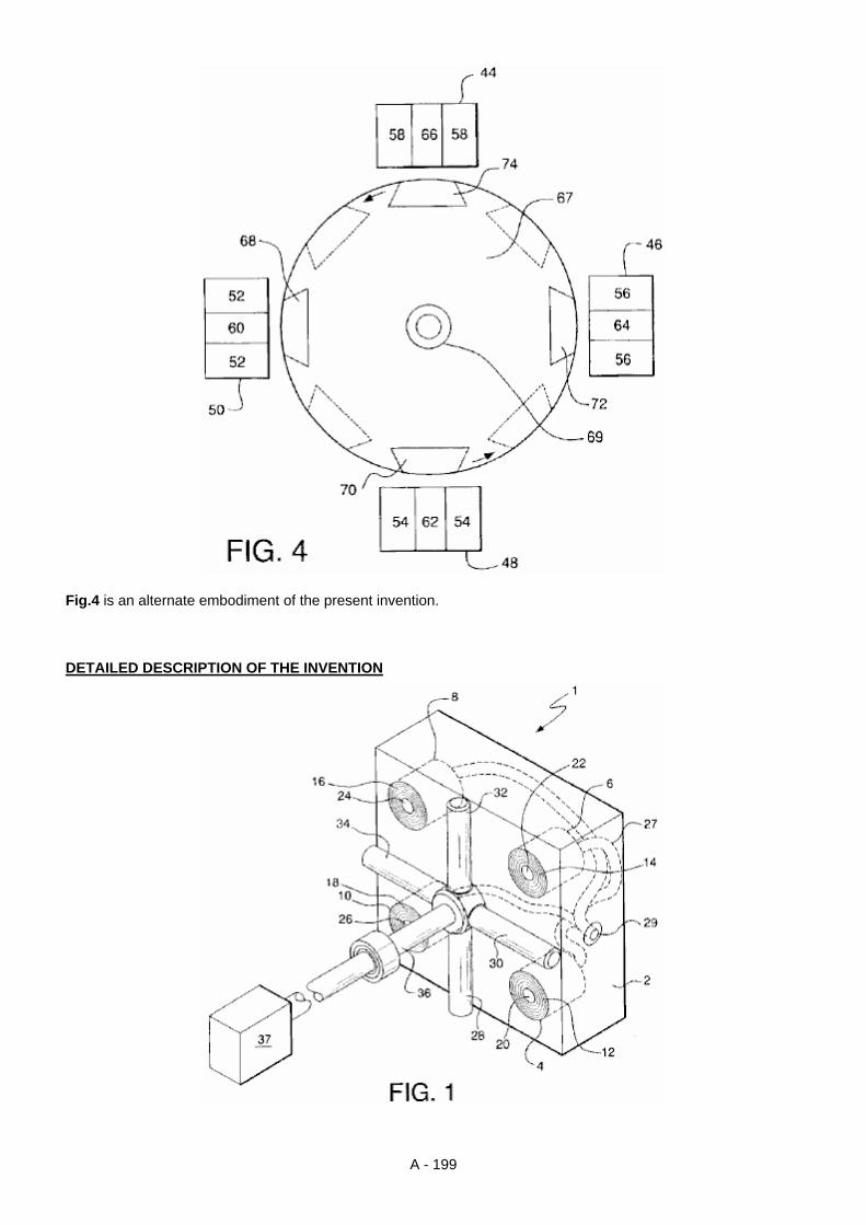
A - 199
Fig.4 is an alternate embodiment of the present invention. DETAILED DESCRIPTION OF THE INVENTION
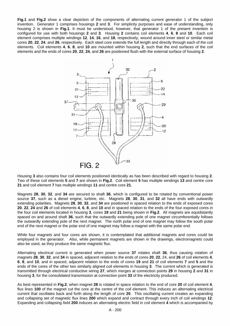
A - 200
Fig.1 and Fig.2 show a clear depiction of the components of alternating current generator 1 of the subject invention. Generator 1 comprises housings 2 and 3. For simplicity purposes and ease of understanding, only housing 2 is shown in Fig.1. It must be understood, however, that generator 1 of the present invention is configured for use with both housings 2 and 3. Housing 2 contains coil elements 4, 6, 8 and 10. Each coil element comprises multiple windings 12, 14, 16, and 18, respectively, wound around inner steel or similar metal cores 20, 22, 24, and 26, respectively. Each steel core extends the full length and directly through each of the coil elements. Coil elements 4, 6, 8, and 10 are mounted within housing 2, such that the end surfaces of the coil elements and the ends of cores 20, 22, 24, and 26 are positioned flush with the external surface of housing 2.
Housing 3 also contains four coil elements positioned identically as has been described with regard to housing 2. Two of these coil elements 5 and 7 are shown in Fig.2. Coil element 5 has multiple windings 13 and centre core 21 and coil element 7 has multiple windings 11 and centre core 21. Magnets 28, 30, 32, and 34 are secured to shaft 36, which is configured to be rotated by conventional power source 37, such as a diesel engine, turbine, etc. Magnets 28, 30, 31, and 32 all have ends with outwardly extending polarities. Magnets 28, 30, 32, and 34 are positioned in spaced relation to the ends of exposed cores 20, 22, 24 and 26 of coil elements 4, 6, 8, and 10 and in spaced relation to the ends of the four exposed cores in the four coil elements located in housing 3, cores 19 and 21 being shown in Fig.2. All magnets are equidistantly spaced on and around shaft 36, such that the outwardly extending pole of one magnet circumferentially follows the outwardly extending pole of the next magnet. The north polar end of one magnet may follow the south polar end of the next magnet or the polar end of one magnet may follow a magnet with the same polar end. While four magnets and four cores are shown, it is contemplated that additional magnets and cores could be employed in the generator. Also, while permanent magnets are shown in the drawings, electromagnets could also be used, as they produce the same magnetic flux. Alternating electrical current is generated when power source 37 rotates shaft 36, thus causing rotation of magnets 28, 30, 32, and 34 in spaced, adjacent relation to the ends of cores 20, 22, 24, and 26 of coil elements 4, 6, 8, and 10, and in spaced, adjacent relation to the ends of cores 19 and 21 of coil elements 7 and 5 and the ends of the cores of the other two similarly aligned coil elements in housing 3. The current which is generated is transmitted through electrical conductive wiring 27, which merges at connection points 29 in housing 2 and 31 in housing 3, for the consolidated transmission at connection point 33 of the electricity produced. As best represented in Fig.2, when magnet 28 is rotated in space relation to the end of core 20 of coil element 4, flux lines 100 of the magnet cut the core at the centre of the coil element. This induces an alternating electrical current that oscillates back and forth along the length of core 20. This oscillating current creates an expanding and collapsing set of magnetic flux lines 200 which expand and contract through every inch of coil windings 12. Expanding and collapsing field 200 induces an alternating electric field in coil element 4 which is accompanied by

A - 201
an expanding and collapsing magnetic field 300. It is noted, significantly, that none of the magnetic field lines 100, 200 and 300, act in a negative fashion or in an opposing action. This allows the subject invention to overcome the limitations of Lenz's law, which states that whenever there is a change in magnetic flux in a circuit, an induced electromotive force is set-up tending to produce a current in a direction which will oppose the flux change.
Fig.3 illustrates an alternate embodiment of the invention to that which is shown in Fig.1. As shown in Fig.3, coil element 44 with outer windings 58 and inner steel core 66, coil element 46 with windings 56 and core 64, coil element 48 with windings 54 and core 62, and coil element 50 with outer windings 52 and core 60 are positioned adjacent to rotor 67, which is mounted on shaft 69. Magnets 68 and 72 are mounted on rotor 67 such that the north poles of the magnets are positioned in spaced relation to coil elements 44, 46, 48 and 50. Magnets 70 and 74 are mounted on rotor 67 such that the south poles of the magnets are also positioned in spaced relation to coil elements 44, 46, 48, and 50. All magnets are fixedly mounted on rotor 67 such that a north pole of one magnet circumferentially follows a south pole of the next magnet in line. The contemplated gap between the magnets and coil element cones is approximately 0.0001 of an inch, although the scope and use of the invention should not be deemed restricted to this distance. As in the prior embodiment, rotation of magnets 68, 70, 72, and 74, by rotation of shaft 69 and hence rotor 67, causes the flux lines of the magnets to cut cores 60, 62, 64, and 66 of coil elements 44, 46, 48, and 50, eventually resulting in the output of electrical current as previously described. It is noted that the larger the diameter of rotor 67, the more coil elements can be positioned around the rotor. The greater the number of coil elements, the slower rotor 67 needs to rotate; however, there is a power loss in so doing. In addition, while rotor 67 is shown as being circular, it may be as square in shape or formed of as other appropriate multi-sided configurations. This unique way of generating electricity allows generation of more electrical power, e.g. anywhere in the range of 4 to 137 times more power, than prior, conventional means. It also has the advantage of obtaining unity power with very little effort. As evidence of such power gains, reference is made to the below outlined experimental outputs from coils and magnets which produced electric power the conventional way compared with the subject invention. The conventional way of generating power, for purpose of the following experimental outputs, as referenced herein, is accomplished by cutting the wires, not the cores, of the coil's windings with the magnet’s flux. In this regard, proof is also provided that the herein described method of generating electrical power is not affected by Lenz's Law, by reference to the readings obtained by the conventional methods as the rpm and size of the coil increase. With conventional methods, the values do not change linearly, but are less because Lenz's Law restricts the outputs from increasing proportionally to the speed and size of the coil. In comparison, however,

A - 202
in the method of producing power of the subject invention, there is an increase in the readings of V (voltage), I (current), and P (power) which are actually larger than anticipated. It is also noted that, just like a transformer, when the number of turns ratio is increased, V increases and I decreases, which is exactly what is seen at the various rpm readings for the different size coils. However, they do not increase or decrease proportionally. Thus, this presents the ideal model for producing electrical power that corresponds to the general law that states that as the speed increases, the voltage will increase proportionally, through the equation: V = q (charge) × v (velocity) × B (magnetic field strength). This also holds true for a coil, in that transformers increase proportionally to the turns ratio. With reference to the voltage outputs for each of the coils, 1100T, 2200T and 5500T, it is seen that they are consistent with the types of voltage outputs for a transformer action. That is to say, as the turns ratio goes up in a transformer so does the voltage. Since the increases in voltage between the number of turns is not exactly 2 to 5 times, one can pick any one of the coils and assume it is accurate and adjust the other coils accordingly. Thus, by fixing the 1100T coil, the other coils become 2837T and 5896T respectively. By fixing the 2200T coil, the other coils become 853T and 4572T respectively. And by fixing the 5500T coil, the other coils become 1026T and 2646T respectively. Also, if the adjustments are made as described here, i.e. that the coils are bigger than originally thought, and they are applied to the voltages for the conventional method of generating power, the voltages do not increase proportionally but are actually smaller than they are supposed to be, additional proof that Lenz's Law has application to conventional generators, but not to this invention. The proportional changes in the voltage relative to speed can also be seen. Thus, considering the 350 RPM speed as accurate, the 1200 RPM and 1300 RPM speeds will adjust to 906 RPM and 1379 RPM respectively. Considering the 1200 RPM speed as accurate, the 350 RPM and 1300 RPM speed becomes 464 RPM and 1826 RPM respectively. And finally, considering the 1300 RPM speed as accurate, the 350 RPM and 1200 RPM speeds become 330 RPM and 854 RPM respectively. It is noted that in using the various RPM readings based upon the above, it is seen that, in the conventional way of generating power, there are losses associated with the measured values. The calculated values again show the application of Lenz's Law in the conventional way of generating power, but not to this invention. In fact, whether or not there is an adjustment of RPM speed or coil size, the power generation of this invention is in no way affected by Lenz's Law. Since Lenz's Law has no effect in this generator, it can be assumed that the voltages increase proportionally to the speed of the magnets rotation. Therefore, one can extrapolate the expected voltages at 1800 RPM, the speed necessary to create 60 Hz. With regard to this generator, for each of the three coils from the 350 RPM, 1200 RPM and 1300 RPM speeds, the following results (values are based on one coil/magnet.):
The reason the current is not changing linearly as the laws of physics imply from transformers, i.e. as voltage goes up based on the number of turns, the current goes down proportionally to the voltage gain, is due to the fact

A - 203
that the inductive reactance is also going up. See the following chart for the inductive reactances for each coil at each speed. Impedance (Z) or inductive reactance (X(L)) for a circuit with only a coil in it is the AC voltage divided by the AC current, and the inductance (L) is Z/2 × pi × F (frequency). For a circuit with a resistor and a coil Z = square root of (R (resistance) squared + X(L) squared)). The following is the chart of impedance Z for all coil sizes at all speeds for the conventional method of generating power and the method of generating power with this invention: Where:
“T” stands for Turns, “CM” stands for Conventional Method and “SI” stands for Subject Invention:
(1) For 350 RPM for 1100T, 2200T and 5500T coils, 1. (a) CM: 0.57v / 56.6 mA = 10.021 ohms = Z
(b) SI: 1.14v / 106.6 mA = 10.694 ohms = Z 2. (a) CM: 0.93v / 32.4 mA = 28.704 ohms = Z
(b) SI: 2.94v / 70.1 mA = 41.94 ohms = Z 3. (a) CM: 2.09v / 17.3 mA = 120.81 ohms = Z
(b) SI: 6.11v / 37.9 mA = 161.21 ohms = Z (2) For 1200 RPM for 1100T, 2200T and 5500T coils: 1. (a) CM: 1.45v / 60.2 mA = 23.387 ohms = Z
(b) SI: 2.95v / 141 mA = 20.922 ohms = Z 2. (a) CM: 3.225v / 36.2 mA = 89.088 ohms = Z
(b) SI: 7.53v / 73.5 mA = 102.449 ohms = Z 3. (a) CM: 4.81v / 17 mA = 282.941 ohms = Z
(b) SI: 11.23v / 31.4 mA = 357.643 ohms = Z (3) For 1300 RPM for 1100T, 2200T and 5500T coils: 1. (a) CM: 1.6v / 83 mA = 19.27 ohms = Z
(b) SI: 4.59v / 157 mA = 29.236 ohms = Z 2. (a) CM: 2.75v / 50.4 mA = 54.455 ohms = Z
(b) SI: 7.74v / 88.5 mA = 87.458 ohms = Z 3. (a) CM: 5.061v / 17.3 mA = 292.543 ohms = Z
(b) SI: 12.76v / 36.4 mA = 350.549 ohms = Z (4) For 400 RPM for 2300T coil with 24 gauge wire and 0.5" core:
(a) CM: 0.15v / 3.7 mA = 40.541 ohms = Z (b) SI: 2.45v / 26.2 mA = 93.511 ohms = Z
(5) For 1200 RPM for 2300T coil with 24 gauge wire and 0.5" core:
(a) CM: 0.37v / 2.7 mA = 137.037 ohms = Z (b) SI: 4.1v / 10.3 mA = 398.058 ohms = Z

A - 204
(6) For 1400 RPM for 2300T coil with 24 gauge wire and 0.5" core:
(a) CM: 0.58v / 2.4 mA = 241.667 ohms = Z (b) SI: 8.3v / 7.8 mA = 1065.385 ohms = Z
(7) For 400 RPM for 2300T coil with 24 gauge wire and 0.75" core:
(a) CM: 0.23v / 4.2 mA = 54.762 ohms = Z (b) SI: 0.37v / 7.2 mA = 51.389 ohms = Z
(8) For 1200 RPM for 2300T coil with 24 gauge wire and 0.75" core:
(a) CM: 0.79v / 3.4 mA = 232.353 ohms = Z (b) SI: 0.43v / 6.9 mA = 207.246 ohms = Z
(9) For 1400 RPM for 2300T coil with 24 gauge wire and 0.75" core:
(a) CM: 0.79v / 3.21 A = 246.875 ohms = Z (b) SI: 2.1v / 2.7 mA = 777.778 ohms = Z
(10) For 400 RPM for 6000T coil with 28 gauge wire and 0.5" core:
(a) CM: 0.49v / 2 mA = 245 ohms = Z (b) SI: 5.48v / 0.13 mA = 421.538 ohms = Z
(11) For 1200 RPM for 6000T coil with 28 gauge wire and 0.5" core:
(a) CM: 1.25v / 1.5 mA = 833.333 ohms = Z (b) SI: 15.04v / 4.1 mA = 3668.293 ohms = Z
(12) For 1400 RPM for 6000T coil with 28 gauge wire and 0.5" core:
(a) CM: 2.08v / 1.1 mA = 1890.909 ohms = Z (b) SI: 18.76v / 2.5 mA = 7504 ohms = Z
(13) For 400 RPM for 6000T coil with 28 gauge wire and 0.75" core:
(a) CM: 0.64v / 1.7 mA = 376.471 ohms = Z (b) SI: 7.97v / 7.4 mA = 1077.027 ohms = Z
(14) For 1200 RPM for 6000T coil with 28 gauge wire and 0.75" core:
(a) CM: 2.08v / 1.3 mA = 1600 ohms = Z (b) SI: 20.4v / 5.6 mA = 3642.857 ohms = Z
(15) For 1400 RPM for 6000T coil with 28 gauge wire and 0.75" core:
(a) CM: 2.28v / 1.2 mA = 1900 ohms = Z (b) SI: 28.4v / 2.1 mA = 13523.81 ohms = Z
It is noted that, based upon the variations of wire size, core size and number of turns, the following effects take place: (a) the smaller the wire size the higher the gains regardless of speed; (b) the greater the number of turns, generally the higher the gains; and (c) the smaller the core size the higher the gains. However, when comparing coils with smaller cores but a higher number of turns, the effects stay about the same.
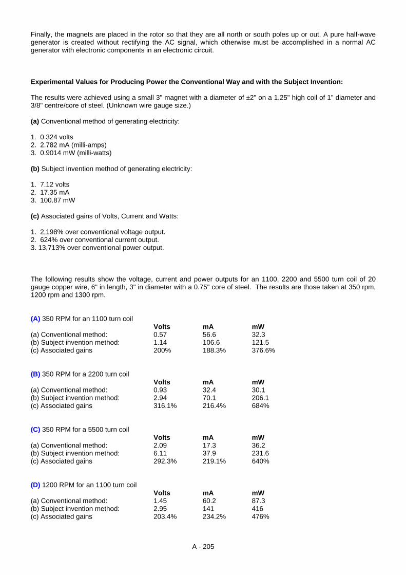
A - 205
Finally, the magnets are placed in the rotor so that they are all north or south poles up or out. A pure half-wave generator is created without rectifying the AC signal, which otherwise must be accomplished in a normal AC generator with electronic components in an electronic circuit. Experimental Values for Producing Power the Conventional Way and with the Subject Invention: The results were achieved using a small 3" magnet with a diameter of ±2" on a 1.25" high coil of 1" diameter and 3/8" centre/core of steel. (Unknown wire gauge size.) (a) Conventional method of generating electricity: 1. 0.324 volts 2. 2.782 mA (milli-amps) 3. 0.9014 mW (milli-watts) (b) Subject invention method of generating electricity: 1. 7.12 volts 2. 17.35 mA 3. 100.87 mW (c) Associated gains of Volts, Current and Watts: 1. 2,198% over conventional voltage output. 2. 624% over conventional current output. 3. 13,713% over conventional power output. The following results show the voltage, current and power outputs for an 1100, 2200 and 5500 turn coil of 20 gauge copper wire, 6" in length, 3" in diameter with a 0.75" core of steel. The results are those taken at 350 rpm, 1200 rpm and 1300 rpm. (A) 350 RPM for an 1100 turn coil Volts mA mW (a) Conventional method: 0.57 56.6 32.3 (b) Subject invention method: 1.14 106.6 121.5 (c) Associated gains 200% 188.3% 376.6% (B) 350 RPM for a 2200 turn coil Volts mA mW (a) Conventional method: 0.93 32.4 30.1 (b) Subject invention method: 2.94 70.1 206.1 (c) Associated gains 316.1% 216.4% 684% (C) 350 RPM for a 5500 turn coil Volts mA mW (a) Conventional method: 2.09 17.3 36.2 (b) Subject invention method: 6.11 37.9 231.6 (c) Associated gains 292.3% 219.1% 640% (D) 1200 RPM for an 1100 turn coil Volts mA mW (a) Conventional method: 1.45 60.2 87.3 (b) Subject invention method: 2.95 141 416 (c) Associated gains 203.4% 234.2% 476%

A - 206
(E) 1200 RPM for a 2200 turn coil Volts mA mW (a) Conventional method: 3.225 36.2 116.75 (b) Subject invention method: 7.53 73.5 553.5 (c) Associated gains 233.5% 203% 474% (F) 1200 RPM on a 5500 turn coil Volts mA mW (a) Conventional method: 4.81 17 81.77 (b) Subject invention method: 11.23 31.4 352.6 (c) Associated gains 235.5% 184.7% 431.3% (G) 1300 RPM on an 1100 turn coil Volts mA mW (a) Conventional method: 1.6 83 132.8 (b) Subject invention method: 4.59 157 704.9 (c) Associated gains 280.6% 189.2% 530.8% (H) 1300 RPM on a 2200 turn coil Volts mA mW (a) Conventional method: 2.75 50.5 138.9 (b) Subject invention method: 7.74 88.5 685 (c) Associated gains 281.5% 175.2% 493.3% (I) 1300 RPM on a 5500 turn coil Volts mA mW (a) Conventional method: 5.061 17.3 87.56 (b) Subject invention method: 12.76 36.4 464.5 (c) Associated gains 252% 210% 530% The following readings are taken from a coil with 24 gauge wire, 0.5" centre/core of steel and 2300T. (A) 400 rpm Volts mA mW (a) Conventional method: 0.15 3.7 0.56 (b) Subject invention method: 2.45 26.2 64.2 (c) Associated gains 1,633% 708% 11,563% (B) 1200 rpm Volts mA mW (a) Conventional method: 0.37 2.7 1 (b) Subject invention method: 4.1 10.3 42.2 (c) Associated gains 1,108% 381% 4,227% (C) 1400 rpm Volts mA mW (a) Conventional method: 0.58 2.4 1.39 (b) Subject invention method: 8.31 7.8 64.82 (c) Associated gains 1,433% 325% 4,657% The following readings are taken from a coil made with 24 gauge wire, 0.75" centre/core of copper, 2300T. (A) 400 rpm
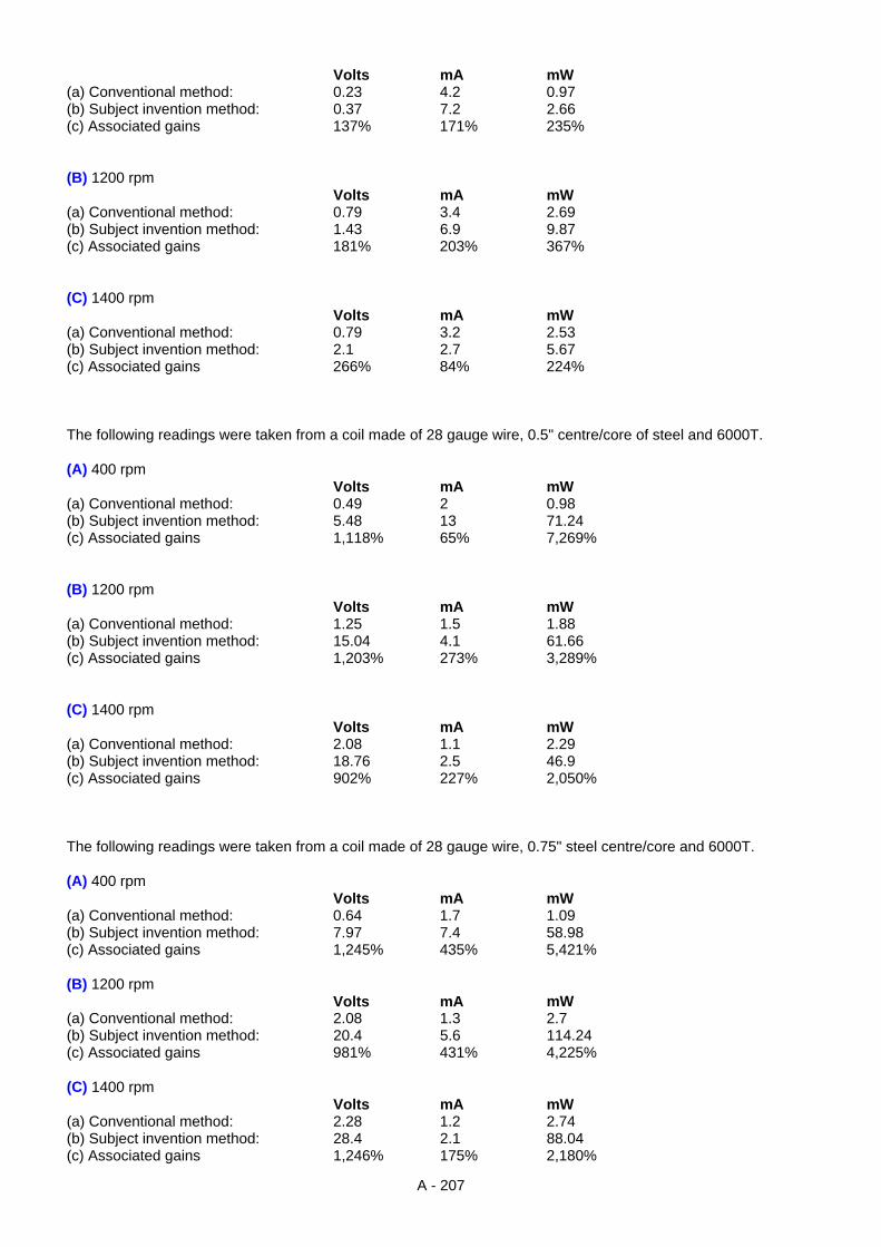
A - 207
Volts mA mW (a) Conventional method: 0.23 4.2 0.97 (b) Subject invention method: 0.37 7.2 2.66 (c) Associated gains 137% 171% 235% (B) 1200 rpm Volts mA mW (a) Conventional method: 0.79 3.4 2.69 (b) Subject invention method: 1.43 6.9 9.87 (c) Associated gains 181% 203% 367% (C) 1400 rpm Volts mA mW (a) Conventional method: 0.79 3.2 2.53 (b) Subject invention method: 2.1 2.7 5.67 (c) Associated gains 266% 84% 224% The following readings were taken from a coil made of 28 gauge wire, 0.5" centre/core of steel and 6000T. (A) 400 rpm Volts mA mW (a) Conventional method: 0.49 2 0.98 (b) Subject invention method: 5.48 13 71.24 (c) Associated gains 1,118% 65% 7,269% (B) 1200 rpm Volts mA mW (a) Conventional method: 1.25 1.5 1.88 (b) Subject invention method: 15.04 4.1 61.66 (c) Associated gains 1,203% 273% 3,289% (C) 1400 rpm Volts mA mW (a) Conventional method: 2.08 1.1 2.29 (b) Subject invention method: 18.76 2.5 46.9 (c) Associated gains 902% 227% 2,050% The following readings were taken from a coil made of 28 gauge wire, 0.75" steel centre/core and 6000T. (A) 400 rpm Volts mA mW (a) Conventional method: 0.64 1.7 1.09 (b) Subject invention method: 7.97 7.4 58.98 (c) Associated gains 1,245% 435% 5,421% (B) 1200 rpm Volts mA mW (a) Conventional method: 2.08 1.3 2.7 (b) Subject invention method: 20.4 5.6 114.24 (c) Associated gains 981% 431% 4,225% (C) 1400 rpm Volts mA mW (a) Conventional method: 2.28 1.2 2.74 (b) Subject invention method: 28.4 2.1 88.04 (c) Associated gains 1,246% 175% 2,180%
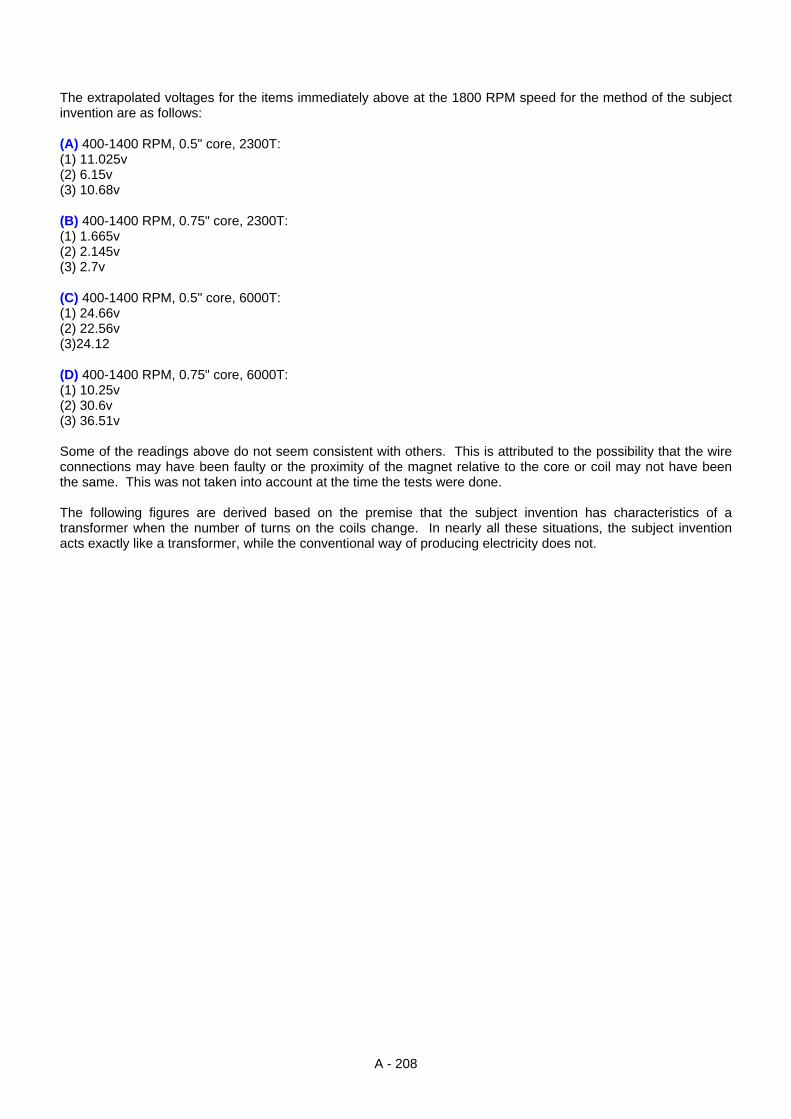
A - 208
The extrapolated voltages for the items immediately above at the 1800 RPM speed for the method of the subject invention are as follows: (A) 400-1400 RPM, 0.5" core, 2300T: (1) 11.025v (2) 6.15v (3) 10.68v (B) 400-1400 RPM, 0.75" core, 2300T: (1) 1.665v (2) 2.145v (3) 2.7v (C) 400-1400 RPM, 0.5" core, 6000T: (1) 24.66v (2) 22.56v (3)24.12 (D) 400-1400 RPM, 0.75" core, 6000T: (1) 10.25v (2) 30.6v (3) 36.51v Some of the readings above do not seem consistent with others. This is attributed to the possibility that the wire connections may have been faulty or the proximity of the magnet relative to the core or coil may not have been the same. This was not taken into account at the time the tests were done. The following figures are derived based on the premise that the subject invention has characteristics of a transformer when the number of turns on the coils change. In nearly all these situations, the subject invention acts exactly like a transformer, while the conventional way of producing electricity does not.
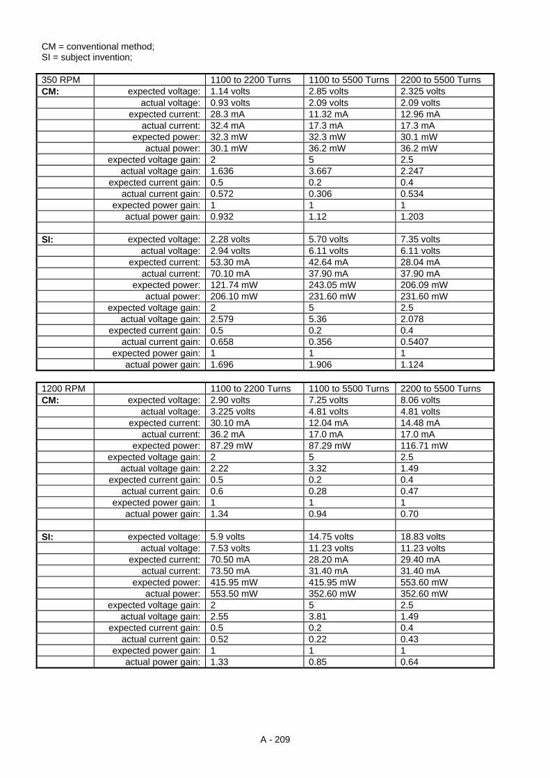
A - 209
CM = conventional method; SI = subject invention; 350 RPM 1100 to 2200 Turns 1100 to 5500 Turns 2200 to 5500 Turns CM: expected voltage: 1.14 volts 2.85 volts 2.325 volts actual voltage: 0.93 volts 2.09 volts 2.09 volts expected current: 28.3 mA 11.32 mA 12.96 mA actual current: 32.4 mA 17.3 mA 17.3 mA expected power: 32.3 mW 32.3 mW 30.1 mW actual power: 30.1 mW 36.2 mW 36.2 mW expected voltage gain: 2 5 2.5 actual voltage gain: 1.636 3.667 2.247 expected current gain: 0.5 0.2 0.4 actual current gain: 0.572 0.306 0.534 expected power gain: 1 1 1 actual power gain: 0.932 1.12 1.203 SI: expected voltage: 2.28 volts 5.70 volts 7.35 volts actual voltage: 2.94 volts 6.11 volts 6.11 volts expected current: 53.30 mA 42.64 mA 28.04 mA actual current: 70.10 mA 37.90 mA 37.90 mA expected power: 121.74 mW 243.05 mW 206.09 mW actual power: 206.10 mW 231.60 mW 231.60 mW expected voltage gain: 2 5 2.5 actual voltage gain: 2.579 5.36 2.078 expected current gain: 0.5 0.2 0.4 actual current gain: 0.658 0.356 0.5407 expected power gain: 1 1 1 actual power gain: 1.696 1.906 1.124 1200 RPM 1100 to 2200 Turns 1100 to 5500 Turns 2200 to 5500 Turns CM: expected voltage: 2.90 volts 7.25 volts 8.06 volts actual voltage: 3.225 volts 4.81 volts 4.81 volts expected current: 30.10 mA 12.04 mA 14.48 mA actual current: 36.2 mA 17.0 mA 17.0 mA expected power: 87.29 mW 87.29 mW 116.71 mW expected voltage gain: 2 5 2.5 actual voltage gain: 2.22 3.32 1.49 expected current gain: 0.5 0.2 0.4 actual current gain: 0.6 0.28 0.47 expected power gain: 1 1 1 actual power gain: 1.34 0.94 0.70 SI: expected voltage: 5.9 volts 14.75 volts 18.83 volts actual voltage: 7.53 volts 11.23 volts 11.23 volts expected current: 70.50 mA 28.20 mA 29.40 mA actual current: 73.50 mA 31.40 mA 31.40 mA expected power: 415.95 mW 415.95 mW 553.60 mW actual power: 553.50 mW 352.60 mW 352.60 mW expected voltage gain: 2 5 2.5 actual voltage gain: 2.55 3.81 1.49 expected current gain: 0.5 0.2 0.4 actual current gain: 0.52 0.22 0.43 expected power gain: 1 1 1 actual power gain: 1.33 0.85 0.64

A - 210
1300 RPM 1100 to 2200 Turns 1100 to 5500 Turns 2200 to 5500 Turns CM: expected voltage: 3.20 volts 8.00 volts 6.88 volts actual voltage: 2.75 volts 5.06 volts 5.06 volts expected current: 41.50 mA 16.60 mA 20.20 mA actual current: 50.50 mA 17.3 mA 17.3 mA expected power: 132.8 mW 132.8 mW 138.98 mW actual power: 138.9 mW 87.56 mW 87.56 mW expected voltage gain: 2 5 2.5 actual voltage gain: 1.72 3.16 1.84 expected current gain: 0.5 0.2 0.4 actual current gain: 0.61 0.21 0.34 expected power gain: 1 1 1 actual power gain: 1.05 0.66 0.63 SI: expected voltage: 9.18 volts 22.95 volts 19.35 volts actual voltage: 7.74 volts 12.76 volts 12.76 volts expected current: 78.50 mA 31.40 mA 35.40 mA actual current: 88.50 mA 36.40 mA 36.40 mA expected power: 720.63 mW 720.63 mW 685.0 mW actual power: 685.0 mW 464.50 mW 464.50 mW expected voltage gain: 2 5 2.5 actual voltage gain: 1.69 2.78 1.65 expected current gain: 0.5 0.2 0.4 actual current gain: 0.56 0.23 0.41 expected power gain: 1 1 1 actual power gain: 0.95 0.64 0.68 The following data represents the expected and actual voltage readings for the conventional method of producing voltage and the method of the subject invention. In virtually all circumstances, the herein invention produced more voltage than the conventional method and has gains that are higher than anticipated. 1100 Turns 350 to 1200 RPM 350 to 1300 RPM 1200 to 1399 RPM CM: expected voltage: 1.954 volts 2.117 volts 1.571 volts actual voltage: 1.45 volts 1.60 volts 1.60 volts expected voltage gain: 3.429 3.714 1.083 actual voltage gain: 2.544 2.807 1.103 SI: expected voltage: 3.909 volts 4.234 volts 3.196 volts actual voltage: 2.95 volts 4.59 volts 4.59 volts expected voltage gain: 3.429 3.714 1.083 actual voltage gain: 2.579 4.026 1.556 2200 Turns 350 to 1200 RPM 350 to 1300 RPM 1200 to 1399 RPM CM: expected voltage: 3.189 volts 3.454 volts 3.494 volts actual voltage: 3.225 volts 5.061 volts 5.061 volts expected voltage gain: 3.429 3.714 1.083 actual voltage gain: 3.468 2.957 0.853 SI: expected voltage: 10.081 volts 10.919 volts 8.157 volts actual voltage: 7.53 volts 7.74 volts 7.74 volts expected voltage gain: 3.429 3.714 1.083 actual voltage gain: 2.561 2.633 1.028

A - 211
5500 Turns 350 to 1200 RPM 350 to 1300 RPM 1200 to 1399 RPM CM: expected voltage: 7.167 volts 7.62 volts 5.211 volts actual voltage: 4.81 volts 5.061 volts 5.061 volts expected voltage gain: 3.429 3.714 1.083 actual voltage gain: 2.301 2.422 1.052 SI: expected voltage: 20.951 volts 22.693 volts 12.166 volts actual voltage: 11.23 volts 12.76 volts 12.76 volts expected voltage gain: 3.429 3.714 1.083 actual voltage gain: 1.838 2.088 1.049 2300 Turns (0.5” core 24 gauge wire) 400 to 1200 RPM 400 to 1400 RPM 1200 to 1400 RPM CM: expected voltage: 0.45 volts 0.525 volts 0.432 volts actual voltage: 0.37 volts 0.58 volts 0.58 volts expected voltage gain: 3.00 3.50 1.167 actual voltage gain: 2.467 3.867 1.568 SI: expected voltage: 7.35 volts 8.57 volts 4.785 volts actual voltage: 4.10 volts 8.31 volts 8.31 volts expected voltage gain: 3.00 3.50 1.167 actual voltage gain: 1.673 3.392 2.027 2300 Turns (0.75” core 24 gauge wire) 400 to 1200 RPM 400 to 1400 RPM 1200 to 1400 RPM CM: expected voltage: 0.69 volts 0.805 volts 0.922 volts actual voltage: 0.79 volts 0.79 volts 0.79 volts expected voltage gain: 3.00 3.50 1.167 actual voltage gain: 3.435 3.435 1.00 SI: expected voltage: 1.11 volts 1.295 volts 1.688 volts actual voltage: 1.43 volts 2.10 volts 2.10 volts expected voltage gain: 3.00 3.50 1.167 actual voltage gain: 3.865 5.676 1.469 6000 Turns (0.5” core 28 gauge wire) 400 to 1200 RPM 400 to 1400 RPM 1200 to 1400 RPM CM: expected voltage: 1.47 volts 1.715 volts 1.459 volts actual voltage: 1.25 volts 2.08 volts 2.08 volts expected voltage gain: 3.00 3.50 1.167 actual voltage gain: 2.551 4.245 1.664 SI: expected voltage: 16.44 volts 19.18 volts 17.668 volts actual voltage: 15.04 volts 18.76 volts 18.76 volts expected voltage gain: 3.00 3.50 1.167 actual voltage gain: 2,745 3.423 11.247 6000 Turns (0.75” core 28 gauge wire) 400 to 1200 RPM 400 to 1400 RPM 1200 to 1400 RPM CM: expected voltage: 1.92 volts 2.24 volts 2.427 volts actual voltage: 2.08 volts 2.28 volts 2.28 volts expected voltage gain: 3.00 3.50 1.167 actual voltage gain: 3.25 3.563 2.427 SI: expected voltage: 23.91 volts 27.895 volts 23.80 volts actual voltage: 20.40 volts 28.40 volts 28.40 volts expected voltage gain: 3.00 3.50 1.167 actual voltage gain: 2.56 3.563 1.392
A - 212
CLAIMS 1. A generator for providing alternating electrical current comprising:
(a) an independently supported rotating drive shaft; (b) a plurality of spaced apart magnets extending outwardly from the shaft, the magnets each creating
magnetic flux and having a polar end with a particular north or south polarity, said magnets being circumferentially spaced and mounted around the shaft, such that the polar ends of the magnets extend away from and circumferentially around the shaft;
(c) a plurality of stationary coil elements, each said coil element comprising electrical windings wound about
substantially the entire coil element, each of said coil elements further comprising a solid metal core with two ends extending substantially through the coil element at the centre of the coil element, each element being positioned such that one end of each of the cores is located in spaced, adjacent relation to the magnets, whereby rotation of the shaft causes rotation of the magnets around the shaft and in spaced, adjacent relation to the cores of the coil elements, the magnetic flux of the magnetics cutting the cores of the coil elements, creating alternating current in the coil elements; and
(d) a first housing in which some of the plurality of coil elements are mounted and a second housing in which
the remainder of the plurality of coil elements are mounted. 2. The generator as in claim 1 wherein the magnets are spaced 90° apart around the shaft. 3. The generator as in claim 1 wherein magnets with north polar ends alternate with the magnets with south polar
ends in spaced, circumferential relation around the shaft. 4. The generator as in claim 1 wherein all the plurality of magnets are magnets with the same polar ends. 5. The generator as in claim 1 wherein the magnets are equidistantly spaced around the shaft. 6. The generator as in claim 1 wherein the plurality of magnets is rotated by the drive shaft between and in
spaced apart relation with the housings. 7. The generator as in claim 1 further comprising four magnets extending from the shaft, adjacent magnets being
positioned perpendicular to each other, each magnet having either an outwardly extending north or south polar end, and said magnets being positioned such that a north polar end magnet follows a south polar end magnet, in spaced, circumferential relation around the shaft.
8. The generator as in claim 1 further comprising multiple north polar end magnets and multiple south polar end
magnets extending from the shaft, said magnets being positioned in spaced, circumferentially relation around the shaft.
9. The generator as in claim 1 in which the shaft is positioned within a rotor and the magnets are circumferentially
mounted on the rotor. 10. The generator as in claim 1 in which the shaft is connected to power means for rotating the shaft, whereby
upon rotation of the shaft, the magnets are rotated around the shaft in spaced relation to the cores of the coil elements, thereby inducing an alternating electrical field along the length of each of the cores, thereby producing an alternating electric current in the windings of the coil elements.
11. The generator as in claim 10 further comprising means to transmit the alternating electrical current for
electrical power usage.
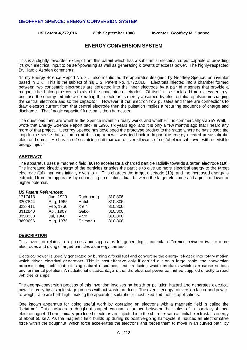
A - 213
GEOFFREY SPENCE: ENERGY CONVERSION SYSTEM
US Patent 4,772,816 20th September 1988 Inventor: Geoffrey M. Spence
ENERGY CONVERSION SYSTEM
This is a slightly reworded excerpt from this patent which has a substantial electrical output capable of providing it’s own electrical input to be self-powering as well as generating kilowatts of excess power. The highly-respected Dr. Harold Aspden comments:
“In my Energy Science Report No. 8I, I also mentioned the apparatus designed by Geoffrey Spence, an inventor based in U.K. This is the subject of his U.S. Patent No. 4,772,816. Electrons injected into a chamber formed between two concentric electrodes are deflected into the inner electrode by a pair of magnets that provide a magnetic field along the central axis of the concentric electrodes. Of itself, this should add no excess energy, because the energy fed into accelerating the electrons is merely absorbed by electrostatic repulsion in charging the central electrode and so the capacitor. However, if that electron flow pulsates and there are connections to draw electron current from that central electrode then the pulsation implies a recurring sequence of charge and discharge. That 'magic capacitor' function is then harnessed. The questions then are whether the Spence invention really works and whether it is commercially viable? Well, I wrote that Energy Science Report back in 1996, six years ago, and it is only a few months ago that I heard any more of that project. Geoffrey Spence has developed the prototype product to the stage where he has closed the loop in the sense that a portion of the output power was fed back to impart the energy needed to sustain the electron beams. He has a self-sustaining unit that can deliver kilowatts of useful electrical power with no visible energy input.”
ABSTRACT The apparatus uses a magnetic field (80) to accelerate a charged particle radially towards a target electrode (10). The increased kinetic energy of the particles enables the particle to give up more electrical energy to the target electrode (10) than was initially given to it. This charges the target electrode (10), and the increased energy is extracted from the apparatus by connecting an electrical load between the target electrode and a point of lower or higher potential. US Patent References: 1717413 Jun, 1929 Rudenberg 310/306. 3202844 Aug, 1965 Hatch 310/306. 3234411 Feb, 1966 Klein 310/306. 3312840 Apr, 1967 Gabor 310/306. 3393330 Jul, 1968 Vary 310/306. 3899696 Aug, 1975 Shimadu 310/306. DESCRIPTION This invention relates to a process and apparatus for generating a potential difference between two or more electrodes and using charged particles as energy carriers. Electrical power is usually generated by burning a fossil fuel and converting the energy released into rotary motion which drives electrical generators. This is cost-effective only if carried out on a large scale, the conversion process being inefficient; utilising natural resources, and producing waste products which can cause serious environmental pollution. An additional disadvantage is that the electrical power cannot be supplied directly to road vehicles or ships. The energy-conversion process of this invention involves no health or pollution hazard and generates electrical power directly by a single-stage process without waste products. The overall energy-conversion factor and power-to-weight ratio are both high, making the apparatus suitable for most fixed and mobile applications. One known apparatus for doing useful work by operating on electrons with a magnetic field is called the "betatron". This includes a doughnut-shaped vacuum chamber between the poles of a specially-shaped electromagnet. Thermionically-produced electrons are injected into the chamber with an initial electrostatic energy of about 50 keV. As the magnetic field builds up during its positive-going half-cycle, it induces an electromotive force within the doughnut, which force accelerates the electrons and forces them to move in an curved path, by
A - 214
interaction with the magnetic field. An important distinction between the betatron and the energy converter of this invention is that in the former the magnetic field has got to be able to increase over a very short period, in order to accelerate the electrons sufficiently, whereas in the latter the magnetic field is virtually constant and the electrons fall inwardly to give up both their kinetic energy and electric charge to a central electrode. The present invention aims at providing an energy converter which may be mobile and which has a permanent magnet or an energised source of magnetic radiation associated with it in order to amplify the electrical energy initially imparted to charge particles fed to, or produced in, a so-called "vacuum" chamber forming part of the generator, which increased energy is extracted from the target electrode on which the particles are incident. Accordingly the present invention provides an energy converter as per the appended claims. While the invention is not to be limited to any particular theory of operation, it is based on the fact that, when a charged particle is constrained to move through a radial distance d (irrespective of the path which it actually follows) through a magnetic field of intensity H, the work done on the particle is H x d. For an electron carrying a charge e, and moving at a speed v over distance d, the total force on the electron is the centripetal force the sum of H x e x v, less the force exerted on the electron in the opposite direction by the centrifugal force, which is the sum of (m x v2)/r. By making the radius of the centre electrode appreciably greater than the orbit of equilibrium, the centrifugal force can be minimised, thus maximising the centripetal force, and hence the work done in bringing the charge to the electrode. The process by which the converter of this invention works uses, as a source of charge, electrically-charged particles, for example electrons and/or ions. Two or more electrodes are housed in a low-pressure chamber. A magnetic field as specified below traverses the chamber: it emanates from a permanent magnet, electromagnet or a source of magnetic radiation. An external source of energy is used to give the charge particles initial kinetic energy, for example by heating, acceleration through an electric field, or from nuclear radiation. The energy-conversion process uses the magnetic field to transfer the charged particles along a desired orbit until they impinge on a central electrode (cathode). The work done on the particles (therefore the electrical potential attained by the cathode) is proportional to the resultant magnetic force times the distance over which the force acts. As the particles move within the chamber they cross the magnetic field. This produces a force acting on the particles, the force being proportional to the field strength, speed and electrical charge of the particles, and the sine of the angle of incidence between the path of the particle and the magnetic lines of force. This force has an angular component and a centripetal one, which forces the particles to travel along a spiral orbit. An opposing centrifugal force also acts on the particles in opposition to the centripetal magnetic force. The electrode potential is proportional to the work required to be done on the charged particles to overcome both the centrifugal force and the electric field around the cathode as the charges accumulate and the potential difference between the electrodes increases. Maximum electrode potential is reached when the centrifugal and repulsive forces are equal to the centripetal force, after which no further charged particles reach the electrode. The radius of the electrode determines the minimal value voltage between the central and an outer electrode: as the central electrode radius is reduced (by sputtering or erosion) the centrifugal force increases, reducing the number of charged particles which can reach the central electrode and therefore the electrode potential, for a given field strength and particle speed. The difference in mass between ions and lighter charged particles, such as electrons, results in different centrifugal forces for given particle kinetic energies. The generator output and efficiency are optimised when the generator uses the maximum magnetic field to minimise the centrifugal force and to maximise the radial distance over which the force acts for a given field strength. Particles having the highest charge-to-mass ratio should be used. Low pressure gases can be used as a charge source when ionised by particle collision and excitation within the chamber. Doped gases can minimise the energy level for ionising gas atoms/molecules thereby improving efficiency. However, the resultant magnetic force is lower for the heavier ions due to their lower velocity so that the electric field radiated by the high voltage electrode (cathode) can attract oppositely charged particles (+ ions) and subsequently discharge the electrode reducing the output voltage. Various methods can be used to overcome or reduce this effect. For example one method would be to separate the opposite charges and/or to use electrical biased grids to control the flow of opposite charges to the high voltage electrode. Gaseous systems are generally more complex than single charge systems, providing higher currents at lower voltages, whereas single charge systems, for example electrons used in high vacuum chambers, can generate higher voltages. The magnetic field can be from one or more permanent magnets and/or from one or more electromagnets; a static magnetic field produces a constant output voltage, while a varying field produces a varying voltage for particles with equal mass and velocity.
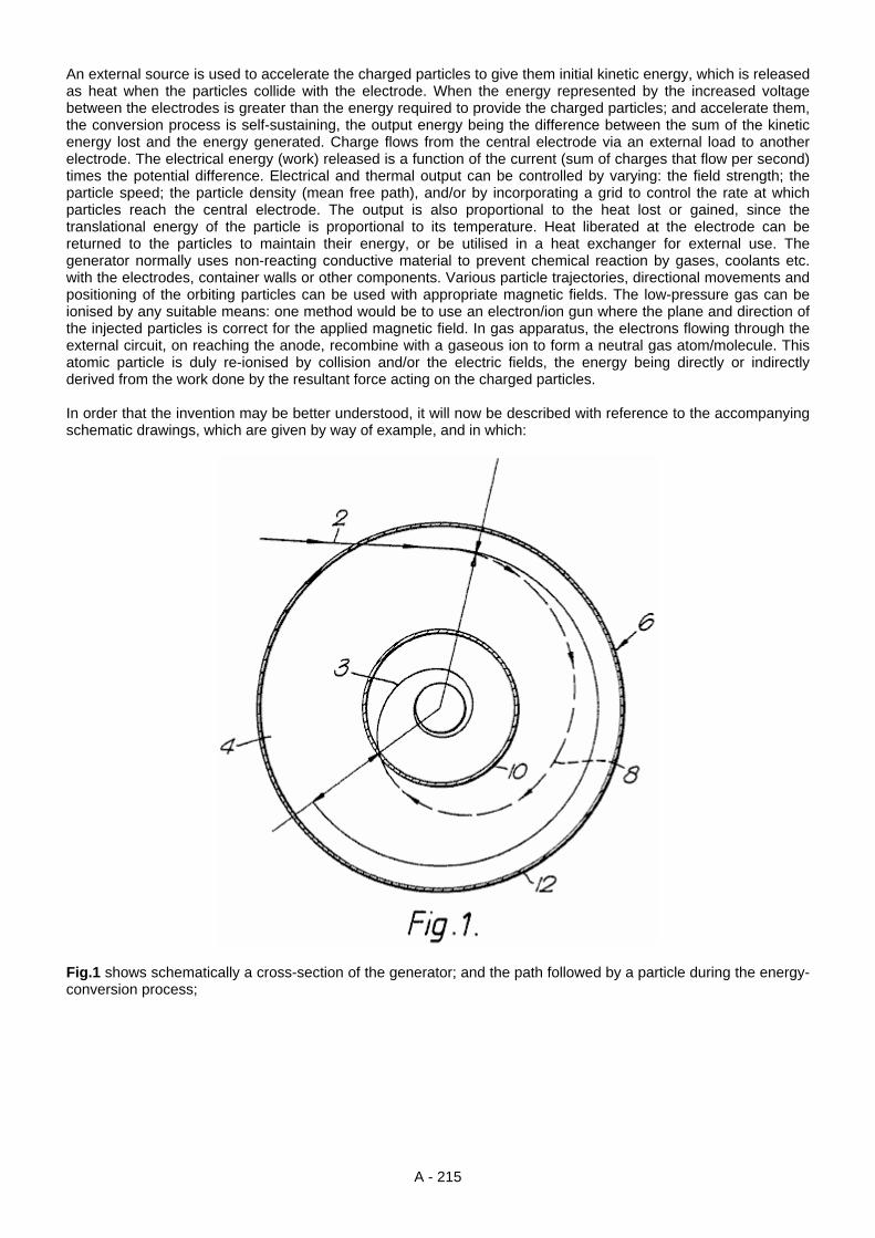
A - 215
An external source is used to accelerate the charged particles to give them initial kinetic energy, which is released as heat when the particles collide with the electrode. When the energy represented by the increased voltage between the electrodes is greater than the energy required to provide the charged particles; and accelerate them, the conversion process is self-sustaining, the output energy being the difference between the sum of the kinetic energy lost and the energy generated. Charge flows from the central electrode via an external load to another electrode. The electrical energy (work) released is a function of the current (sum of charges that flow per second) times the potential difference. Electrical and thermal output can be controlled by varying: the field strength; the particle speed; the particle density (mean free path), and/or by incorporating a grid to control the rate at which particles reach the central electrode. The output is also proportional to the heat lost or gained, since the translational energy of the particle is proportional to its temperature. Heat liberated at the electrode can be returned to the particles to maintain their energy, or be utilised in a heat exchanger for external use. The generator normally uses non-reacting conductive material to prevent chemical reaction by gases, coolants etc. with the electrodes, container walls or other components. Various particle trajectories, directional movements and positioning of the orbiting particles can be used with appropriate magnetic fields. The low-pressure gas can be ionised by any suitable means: one method would be to use an electron/ion gun where the plane and direction of the injected particles is correct for the applied magnetic field. In gas apparatus, the electrons flowing through the external circuit, on reaching the anode, recombine with a gaseous ion to form a neutral gas atom/molecule. This atomic particle is duly re-ionised by collision and/or the electric fields, the energy being directly or indirectly derived from the work done by the resultant force acting on the charged particles. In order that the invention may be better understood, it will now be described with reference to the accompanying schematic drawings, which are given by way of example, and in which:
Fig.1 shows schematically a cross-section of the generator; and the path followed by a particle during the energy-conversion process;
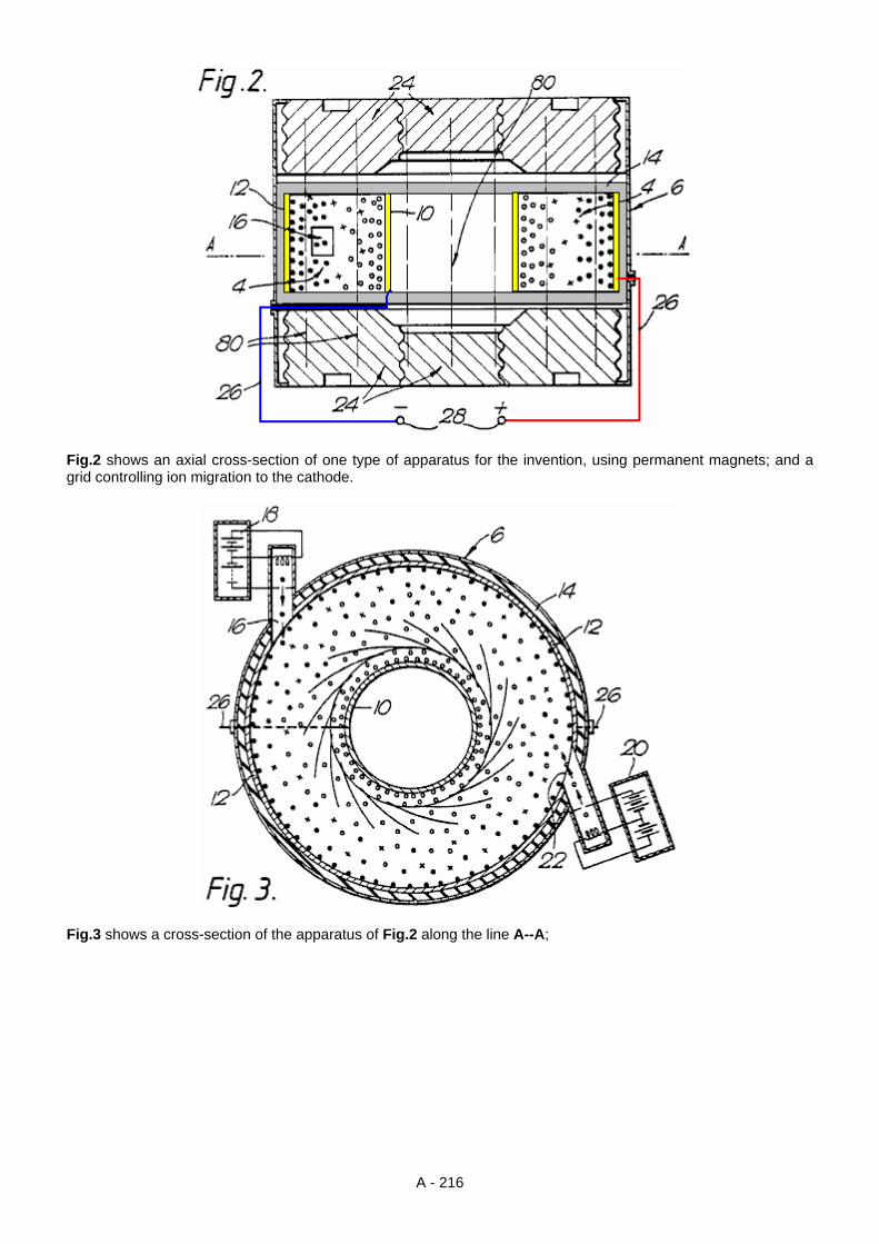
A - 216
Fig.2 shows an axial cross-section of one type of apparatus for the invention, using permanent magnets; and a grid controlling ion migration to the cathode.
Fig.3 shows a cross-section of the apparatus of Fig.2 along the line A--A;
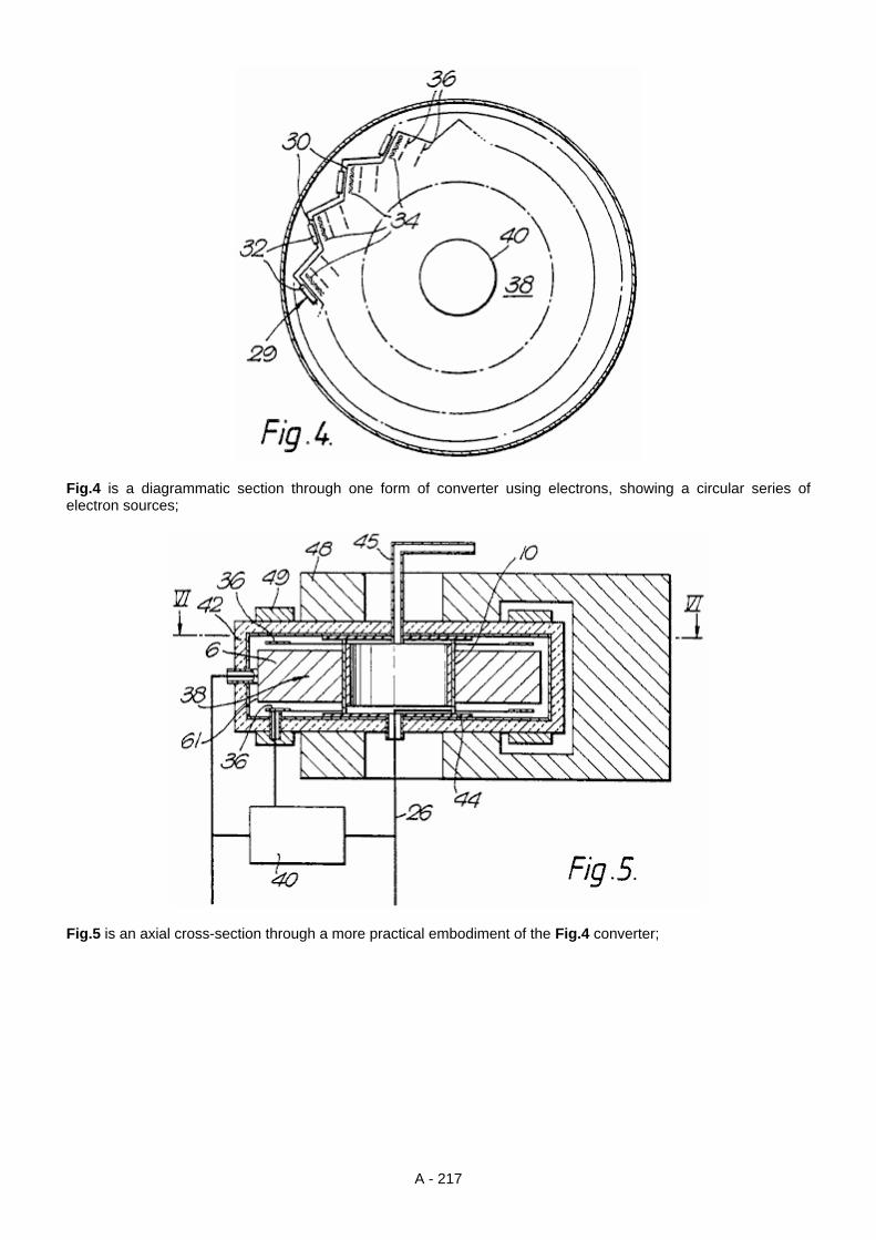
A - 217
Fig.4 is a diagrammatic section through one form of converter using electrons, showing a circular series of electron sources;
Fig.5 is an axial cross-section through a more practical embodiment of the Fig.4 converter;
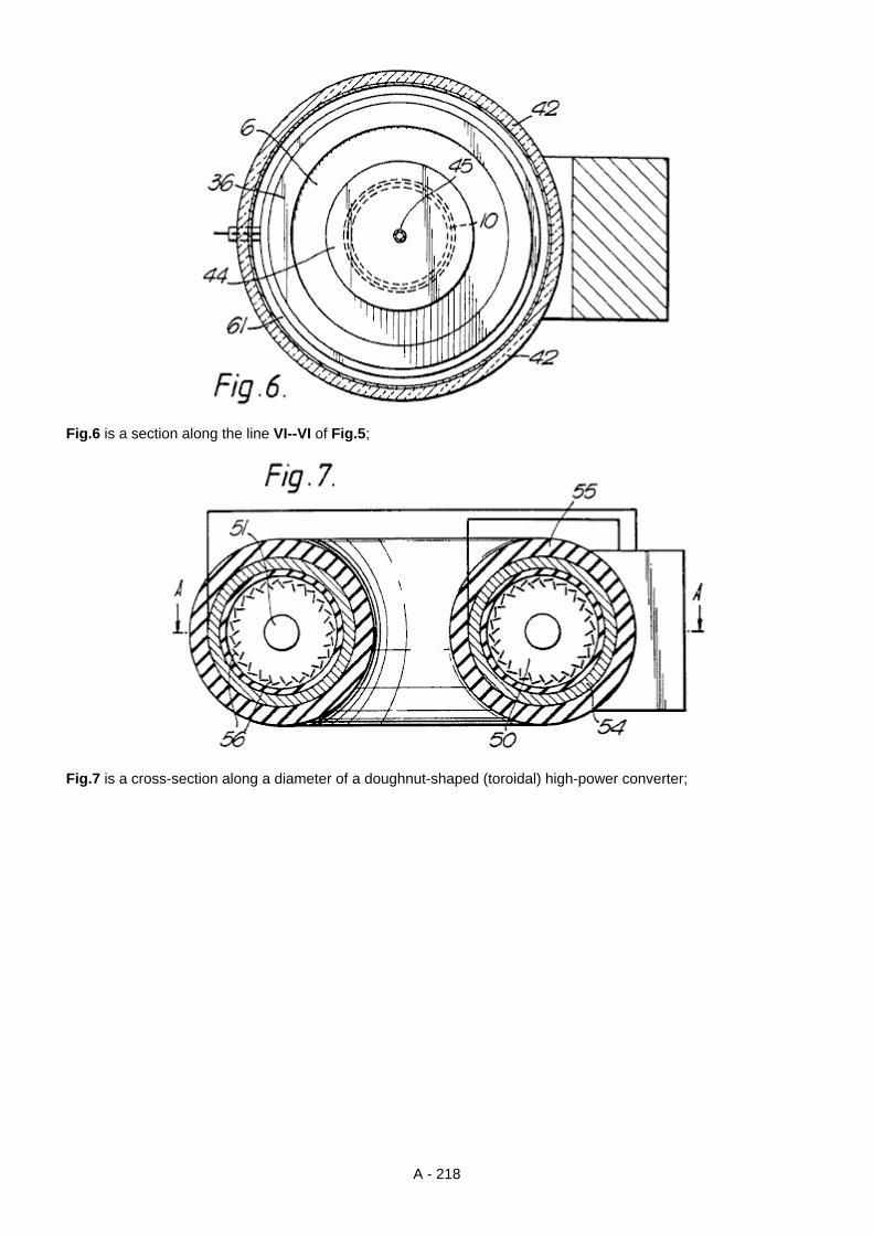
A - 218
Fig.6 is a section along the line VI--VI of Fig.5;
Fig.7 is a cross-section along a diameter of a doughnut-shaped (toroidal) high-power converter;

A - 219
Fig.8 is a section on line A--A of Fig.7, and
Fig.9 is a scheme of a two-stage converter, using both forms of charged particles concurrently.
A - 220
As shown in Fig.1, a charged particle is injected along a trajectory 2 into a magnetic field extending normal to the plane of the drawing. The field permeates the space 4 of the annular cross-section within a cylindrical chamber 6. The magnetic field produces a force on the particle, extending at right angles to both it’s direction of motion and the magnetic field. The resultant centripetal force causes the particle to follow a spiral path 8 ending on the central electrode 10 spaced radially inwards from the outer cylindrical electrode 12. The extra energy acquired by the particle is a function of the radial distance travelled and the strength of the magnetic field between the electrodes. This energy is given up on impact with the central electrode, in the form of heat and/or work done in bringing the charge against the opposing electric field to the electrode. In the absence of the central electrode 10, the electrons would follow the orbit of equilibrium 3, this being the orbit followed by a particle when the centrifugal and centripetal forces balance, resulting in no work being done on the particle.
A - 221
As shown more particularly in Fig.2 and Fig.3, the energy converter 1 consists basically of a annular chamber 6 having an outer cylindrical electrode 12; an inner cylindrical electrode 10, and two gas-tight walls 14 of electrical insulation material. In the electrode 12 is a port 22 through which an electron gun 20 can inject electrons into space 4. Additionally or alternatively, an ion gun 18 can inject positively-charged particles through port 16. Seated on the major flat surfaces of chamber 6 are magnetic pole-pieces 24 giving rise to a uniform magnetic field 80 which traverses the space 4 parallel with the axis of chamber 6. The magnets may be ceramic permanent magnets, or they may be electromagnets. In either case, means (not shown) may be provided for adjusting the magnetic field strength. Heavy conductors 26 connect the two electrodes to terminals 28 across which a resistive load can be placed to dissipate the generator output. A vacuum pump (not shown) has its inlet in communication with the interior of chamber 6 so that the gas pressure in the generator can be reduced to, and kept at, a desired sub-atmospheric value. Associated with the pump, or separate from it, may be means for ensuring that the gas in the generator is of a desired composition, for instance, one which enhances the possibility of ionising collisions between the charged particles and gas atoms or molecules. One such suitable gas would be neon containing 0.1% argon by volume. In order to cause the generator to start working, it is necessary to start the vacuum pump and to energise the electron gun or each particle source. The latter involves heating a filament from an external source of power until the required internal energy level (temperature) is reached which in turn causes a piece of thermo-emissive material to emit electrons. If the electrons are to be the charge carriers, they are accelerated by a suitable electric field and projected into the space 4. Here they are further accelerated by the radial electric field between the electrodes, and at the same time have a deflecting force applied to them by the axial magnetic field through which they pass. For an ion source, the electrons are accelerated until they impact some atoms or molecules, to produce a stream of ions which likewise pass into the space 4. With the polarities shown, the electrons are attracted to the central electrode, while the ions are pulled towards the outer electrode, which accounts for the different orientations of sources 18 and 20. Any gas molecules which pass close to, or between, the electrodes are ionised by collision and/or the electrostatic field. Output current can then be taken through a load impedance connected across terminals 28. The impedance is matched to prevent the internal process energy dropping below a value which would prevent the re-ionisation of the gaseous atoms. As each ion is deionised at the anode, the gas atoms will tend to continue to circulate until re-ionised, the resultant force drawing both the ions (shown by solid circles) and electrons (shown by hollow circles) back into their respective orbits.

A - 222
It is envisaged that, in the case of a converter using electrons, the chamber could be evacuated to a chosen sub-atmospheric pressure and sealed. In that form of the invention shown in Fig.4, each electron source forming one of a circular series 29 of sources has a body 30 of electro-emissive material, such as molybdenum coated by caesium, heated by an electric filament 32 connected in series or parallel across a source of electric power (not shown). Immediately in front of each emitter 30 is a grid 34 of fine wires, all the grids being connected with a source of adjustable voltage so as to control the flow of electrons from the emitter. These electrons are projected through one or more acceleration electrodes 36 across which a potential difference is established along the electron path, so that each incremental electron source injects a stream of electrons having known kinetic energy into a space 38, indicated by the circle shown in a broken line, traversed by the deflection magnetic field, within which is the central, target, electrode 40. The stream of electrons injected into the magnetic field may be focused by electric and/or magnetic fields. In the remaining Figs, those parts already referred to will retain the same references.
In the "flat disc" configuration shown in Fig.5, the annular chamber 6 is enclosed in a body 42 of thermal insulation material. The central electrode 10 is seated on insulators 44 which are pierced by conduits 45 for the passage of a coolant fluid and by an output lead 26, which may extend along the conduit so that it too is cooled. Fig.5 shows how the deflection magnet is generally U-shaped, and has two annular pole-pieces 48, so that the magnetic field is uniform between the surface of electrode 10 and the region 38 radially innermost of the circular electron source, the electric field between the electrode 36 and emission surface 61 providing the electrons initial accelerations (kinetic energy). Fig.5 also shows how a voltage is tapped off the resistive load 40 (which thus functions as a potentiometer) and is fed through to the acceleration electrode 36. Chamber 6 is also provided with two annular magnets 49 (or a circular series of incremental magnets) designed to influence the direction along which the electrons pass into space 38. The magnets provide local magnetic fields to ensure that the electrons meet the boundary of space 38 tangentially, i.e. with zero radial velocity.
A - 223

A - 224
In that form of the invention shown in Fig.7 and Fig.8, the individual "flat disc" converters of Fig.5 and Fig.6 are arranged in a type of "circular" construction, such that the magnetic fields extend along the axis of the resulting toroidal space 50 penetrated by a single toroidal target electrode 51 through which a coolant fluid may pass, along conduits 52. The cross-section of Fig.8 shows that the magnetic fields are supplemented by an electric field produced by windings 53 wound on a magnetic core 54 bounded by insulation 55. Apart from the fact that the electrodes are common to all converters, each functions individually as described above. Obviously the power source driving the heaters for the electron guns 56; the electromagnets (if any); the acceleration electrodes and the control grids, have to be of sufficient capacity to supply the greater power needed to drive this "toroidal" configuration. Some changes would need to be made to the physical dimensioning and positioning of the relatively-complex construction, but as all these are readily understood by a competent engineer, they are not further described in this specification.
A - 225
As already mentioned, the converters of this invention are of two types, i.e. electronic and ionic. Fig.9 shows diagrammatically how they may be combined to take advantage of their differences. In the two-stage power generation apparatus shown in Fig.9 the first stage consists of an ioniser 520 supplying a mixture of charged particles, i.e. ions and electrons, to a separator 540, which supplies electrons to a second stage consisting of a sealed electronic converter 560 in parallel with a gaseous ionic converter 580. The separator 540 may use the different particle masses to separate them centrifugally using, for example, the energy conversion system of Fig.1 (without the target electrode), or it may use electromagnetic deflection fields, or a physical diffusion process, either alone or in combination. As this is not part of the subject-matter of this invention, it will not be described herein in any further detail. In the generators of Fig.6 and Fig.8, the respective particles are deflected magnetically and accelerated radially, to function as already described above. Because each generator is designed to operate most effectively with its particular form of charge carrier, it can be designed optimally, thus reducing the energy absorption caused by ions and electrons recombining before each has fallen on its respective target electrode. Because the electronic converter would finish up with a negatively-charged electrode, whereas the converse is true for the ionic converter, the load 400 extracting energy from the apparatus is connected across the two target electrodes. The other two electrodes of the converters may be held at the same potential, as by being connected together, or their potentials may float. The generator can be designed to produce a wide range of output voltages and currents. The lower-energy generators are light enough to be mobile, so that they can power vehicles or act as stand-by generators. Various electrode and magnet configurations can be used, and the generators can be connected in series or parallel. Cooling jackets are fitted to prevent overheating in high-powered apparatus, and the generator is enclosed within a thermally-insulating jacket to reduce heat losses thereby increasing particle velocities. For high-energy generators, it may be necessary to provide for forced cooling of the inner electrode, as by fins projecting therefrom into a high-speed stream of suitable coolant. Although the process according to this invention is particularly suited to using external electrical energy, it must be understood that other sources can be used to provide the initial energy input, e.g. solar and waste process heat are some of the varied energy sources which could be utilised. Control of the charge-generation process can be achieved by other means, including one or more electrically-biased grids, as used in thermionic valves. CLAIMS 1. An energy conversion process for generating an electric potential, the process comprising; providing a source
of electric charge carriers of predetermined polarity, accelerating the carriers away from the source, introducing the carriers into a magnetic field transverse to the path of the carriers in a process chamber, the field bounding an inner electrode within the chamber such that the carriers orbit the electrode while accelerating radially toward the electrode; and converting the resulting increased kinetic energy of the carriers

A - 226
into an electric potential at the electrode before the carriers reach an orbit of equilibrium in which the centripetal force is balanced by the centrifugal force on the carriers.
2. A process according to claim 1 in which the electric potential is created between the inner electrode and an
outer electrode radially spaced from the inner electrode. 3. A process according to claim 2 in which the outer electrode provides the said source of the charge carriers. 4. A process according to claim 1 or claim 2 in which the chamber is maintained at a sub-atmospheric pressure. 5. A process according to claim 1 in which the electric potential drives a load connected between the inner
electrode and a point remote from the electrode. 6. A process according to claim 1 or claim 2 in which the electric charge carriers comprise electrons or ions. 7. A process according to claim 1 in which further charge carriers of the opposite polarity traverse the magnetic
field and accumulate at a second electrode to increase the potential difference between the two electrodes. 8. A process according to claim 1 in which electrically biased grids control the flow of the charge carriers from the
source. 9. A process according to claim 1 in which the charge carriers are separated from charge carriers of the opposite
polarity before being introduced into the magnetic field. 10. A process according to claim 9 in which the charge carriers of opposite polarity are introduced into a
corresponding second magnetic field, whereby a potential difference is produced between respective electrodes in each field.
11. A process according to claim 1 in which the carriers are injected into the magnetic field. 12. A process according to claim 11 in which the injection energy is produced by accelerating the carriers through
an electric field. 13. A process according to claim 11 in which the injection energy is produced by accelerating the carriers through
a magnetic field. 14. A process according to claim 1 in which the injection energy of the carriers is produced by nuclear emission. 15. A process according to claim 1 in which the injection energy of the carriers is produced by heat. 16. A process according to claim 1 in which the generated electric potential is directly or indirectly used to
maintain the generation of charge carriers or the internal temperature of the space traversed by the magnetic field, or the applied magnetic field.
17. A process according to claim 1 in which the generated electric potential is directly or indirectly used to
maintain the generation of charge carriers and the internal temperature of the space traversed by the magnetic field and the applied magnetic field.
18. An energy converter including a source of electric charge carriers of a predetermined polarity, a process
chamber having an inner electrode, means for accelerating the carriers away from the source and for introducing the carriers into the chamber, means for applying a magnetic field transverse to the path of the carriers and bounding the inner electrode of the chamber such that the carriers orbit the electrode while accelerating radially toward the electrode, the electrode being located at a radius which exceeds the equilibrium radius for the carrier mean velocity and applied field strength and intercepting the carriers such that the increased kinetic energy of the carriers due to centripetal acceleration is converted to an electric potential at the electrode.
19. An energy converter according to claim 18 in which the chamber includes an outer electrode spaced radially
from the inner electrode, and means for injecting the charge carriers into the space between the electrodes. 20. An energy converter according to claim 19 in which the outer electrode provides the said source of charge
carriers. 21. An energy converter according to claim 19 further comprising an insulating wall bounding the outer electrode.

A - 227
22. A converter according to claim 18 further comprising means for maintaining the chamber at a predetermined sub-atmospheric pressure.
23. A converter according to claim 19 in which the outer electrode has at least one port through which the charge
carriers can be injected into the chamber along a desired trajectory. 24. A converter according to claim 23 in which the outer electrode has plural ports and each port communicates
with a thermionic source of the respective carriers. 25. A converter according to claim 18 in which the chamber is a vacuum chamber. 26. A converter according to claim 18 further comprising electrically biased grids for controlling the flow of charge
carriers from the source. 27. A converter according to claim 22 or claim 25 in which the evacuated chamber comprises a sealed unit. 28. A converter according to claim 18 further comprising means for adjusting the strength of the applied magnetic
field. 29. A converter according to claim 18 in which the chamber is filled with low pressure gas.
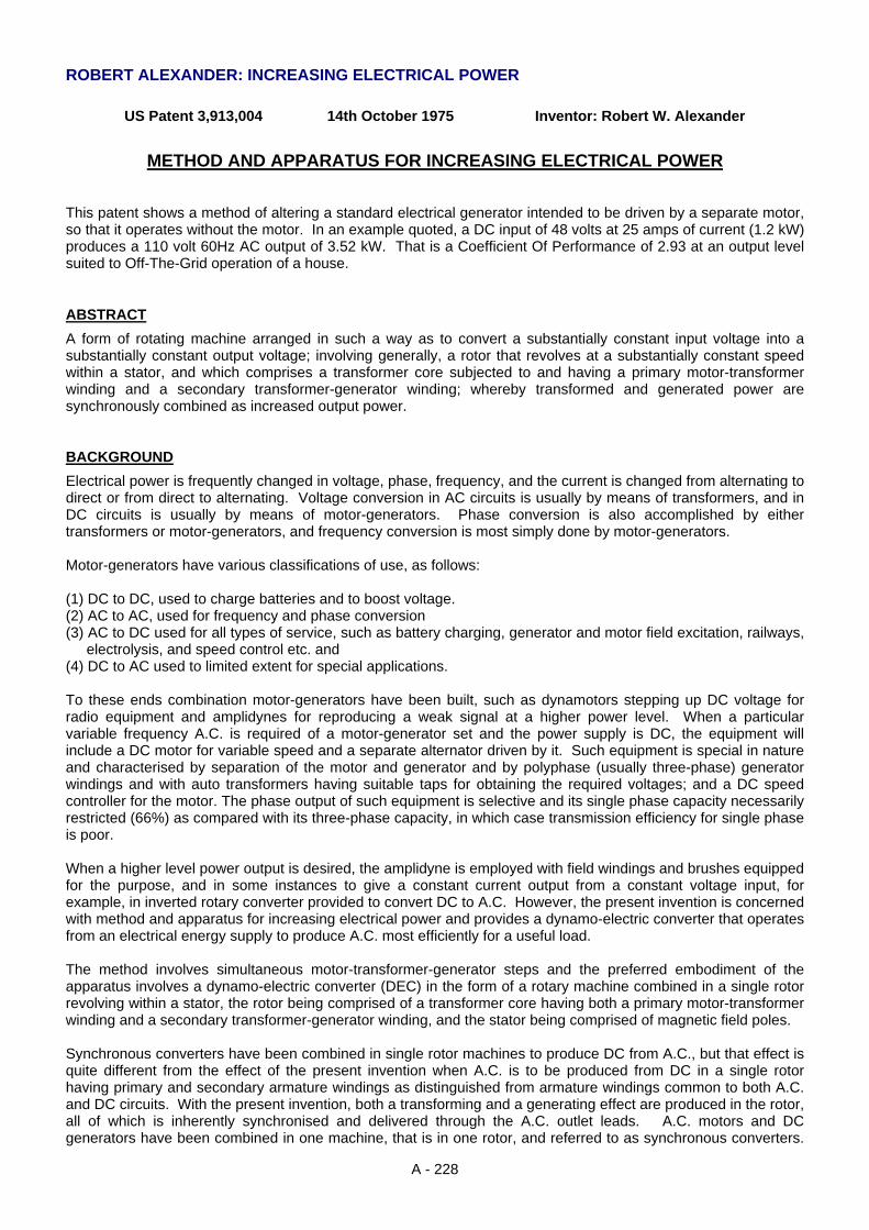
A - 228
ROBERT ALEXANDER: INCREASING ELECTRICAL POWER
US Patent 3,913,004 14th October 1975 Inventor: Robert W. Alexander
METHOD AND APPARATUS FOR INCREASING ELECTRICAL POWER
This patent shows a method of altering a standard electrical generator intended to be driven by a separate motor, so that it operates without the motor. In an example quoted, a DC input of 48 volts at 25 amps of current (1.2 kW) produces a 110 volt 60Hz AC output of 3.52 kW. That is a Coefficient Of Performance of 2.93 at an output level suited to Off-The-Grid operation of a house. ABSTRACT A form of rotating machine arranged in such a way as to convert a substantially constant input voltage into a substantially constant output voltage; involving generally, a rotor that revolves at a substantially constant speed within a stator, and which comprises a transformer core subjected to and having a primary motor-transformer winding and a secondary transformer-generator winding; whereby transformed and generated power are synchronously combined as increased output power. BACKGROUND Electrical power is frequently changed in voltage, phase, frequency, and the current is changed from alternating to direct or from direct to alternating. Voltage conversion in AC circuits is usually by means of transformers, and in DC circuits is usually by means of motor-generators. Phase conversion is also accomplished by either transformers or motor-generators, and frequency conversion is most simply done by motor-generators. Motor-generators have various classifications of use, as follows: (1) DC to DC, used to charge batteries and to boost voltage. (2) AC to AC, used for frequency and phase conversion (3) AC to DC used for all types of service, such as battery charging, generator and motor field excitation, railways,
electrolysis, and speed control etc. and (4) DC to AC used to limited extent for special applications. To these ends combination motor-generators have been built, such as dynamotors stepping up DC voltage for radio equipment and amplidynes for reproducing a weak signal at a higher power level. When a particular variable frequency A.C. is required of a motor-generator set and the power supply is DC, the equipment will include a DC motor for variable speed and a separate alternator driven by it. Such equipment is special in nature and characterised by separation of the motor and generator and by polyphase (usually three-phase) generator windings and with auto transformers having suitable taps for obtaining the required voltages; and a DC speed controller for the motor. The phase output of such equipment is selective and its single phase capacity necessarily restricted (66%) as compared with its three-phase capacity, in which case transmission efficiency for single phase is poor. When a higher level power output is desired, the amplidyne is employed with field windings and brushes equipped for the purpose, and in some instances to give a constant current output from a constant voltage input, for example, in inverted rotary converter provided to convert DC to A.C. However, the present invention is concerned with method and apparatus for increasing electrical power and provides a dynamo-electric converter that operates from an electrical energy supply to produce A.C. most efficiently for a useful load. The method involves simultaneous motor-transformer-generator steps and the preferred embodiment of the apparatus involves a dynamo-electric converter (DEC) in the form of a rotary machine combined in a single rotor revolving within a stator, the rotor being comprised of a transformer core having both a primary motor-transformer winding and a secondary transformer-generator winding, and the stator being comprised of magnetic field poles. Synchronous converters have been combined in single rotor machines to produce DC from A.C., but that effect is quite different from the effect of the present invention when A.C. is to be produced from DC in a single rotor having primary and secondary armature windings as distinguished from armature windings common to both A.C. and DC circuits. With the present invention, both a transforming and a generating effect are produced in the rotor, all of which is inherently synchronised and delivered through the A.C. outlet leads. A.C. motors and DC generators have been combined in one machine, that is in one rotor, and referred to as synchronous converters.
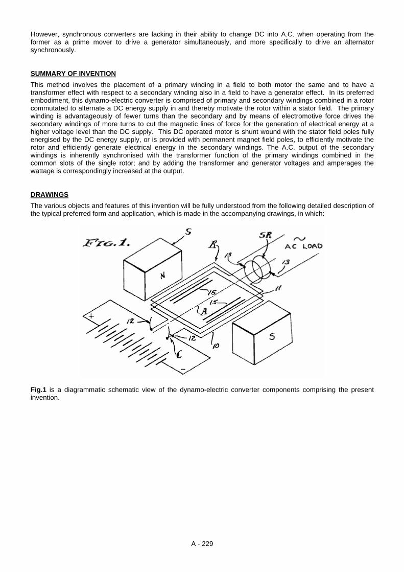
A - 229
However, synchronous converters are lacking in their ability to change DC into A.C. when operating from the former as a prime mover to drive a generator simultaneously, and more specifically to drive an alternator synchronously. SUMMARY OF INVENTION This method involves the placement of a primary winding in a field to both motor the same and to have a transformer effect with respect to a secondary winding also in a field to have a generator effect. In its preferred embodiment, this dynamo-electric converter is comprised of primary and secondary windings combined in a rotor commutated to alternate a DC energy supply in and thereby motivate the rotor within a stator field. The primary winding is advantageously of fewer turns than the secondary and by means of electromotive force drives the secondary windings of more turns to cut the magnetic lines of force for the generation of electrical energy at a higher voltage level than the DC supply. This DC operated motor is shunt wound with the stator field poles fully energised by the DC energy supply, or is provided with permanent magnet field poles, to efficiently motivate the rotor and efficiently generate electrical energy in the secondary windings. The A.C. output of the secondary windings is inherently synchronised with the transformer function of the primary windings combined in the common slots of the single rotor; and by adding the transformer and generator voltages and amperages the wattage is correspondingly increased at the output. DRAWINGS The various objects and features of this invention will be fully understood from the following detailed description of the typical preferred form and application, which is made in the accompanying drawings, in which:
Fig.1 is a diagrammatic schematic view of the dynamo-electric converter components comprising the present invention.
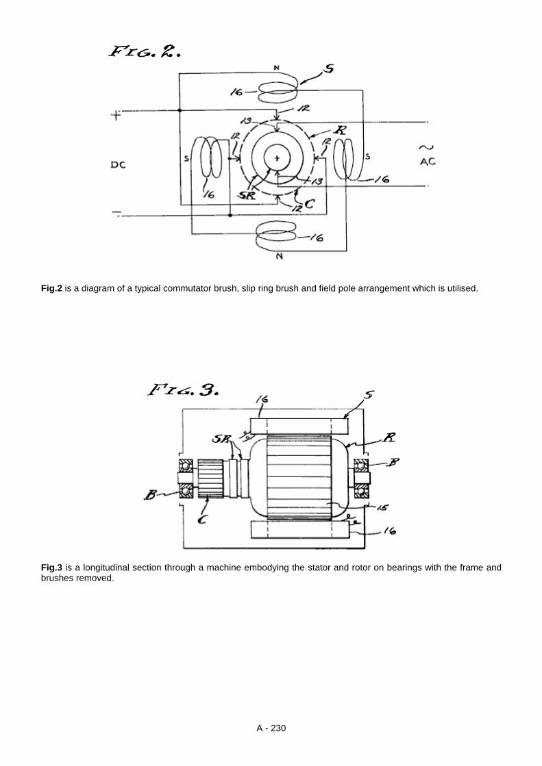
A - 230
Fig.2 is a diagram of a typical commutator brush, slip ring brush and field pole arrangement which is utilised.
Fig.3 is a longitudinal section through a machine embodying the stator and rotor on bearings with the frame and brushes removed.
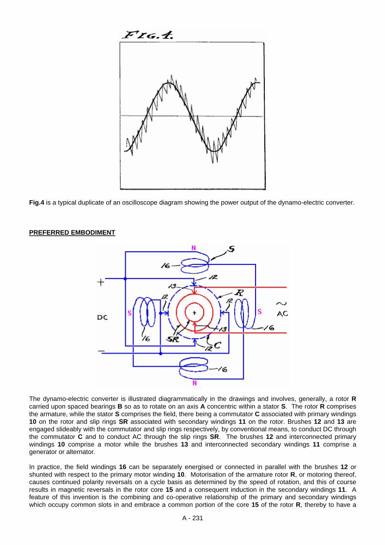
A - 231
Fig.4 is a typical duplicate of an oscilloscope diagram showing the power output of the dynamo-electric converter. PREFERRED EMBODIMENT
The dynamo-electric converter is illustrated diagrammatically in the drawings and involves, generally, a rotor R carried upon spaced bearings B so as to rotate on an axis A concentric within a stator S. The rotor R comprises the armature, while the stator S comprises the field, there being a commutator C associated with primary windings 10 on the rotor and slip rings SR associated with secondary windings 11 on the rotor. Brushes 12 and 13 are engaged slideably with the commutator and slip rings respectively, by conventional means, to conduct DC through the commutator C and to conduct AC through the slip rings SR. The brushes 12 and interconnected primary windings 10 comprise a motor while the brushes 13 and interconnected secondary windings 11 comprise a generator or alternator. In practice, the field windings 16 can be separately energised or connected in parallel with the brushes 12 or shunted with respect to the primary motor winding 10. Motorisation of the armature rotor R, or motoring thereof, causes continued polarity reversals on a cycle basis as determined by the speed of rotation, and this of course results in magnetic reversals in the rotor core 15 and a consequent induction in the secondary windings 11. A feature of this invention is the combining and co-operative relationship of the primary and secondary windings which occupy common slots in and embrace a common portion of the core 15 of the rotor R, thereby to have a
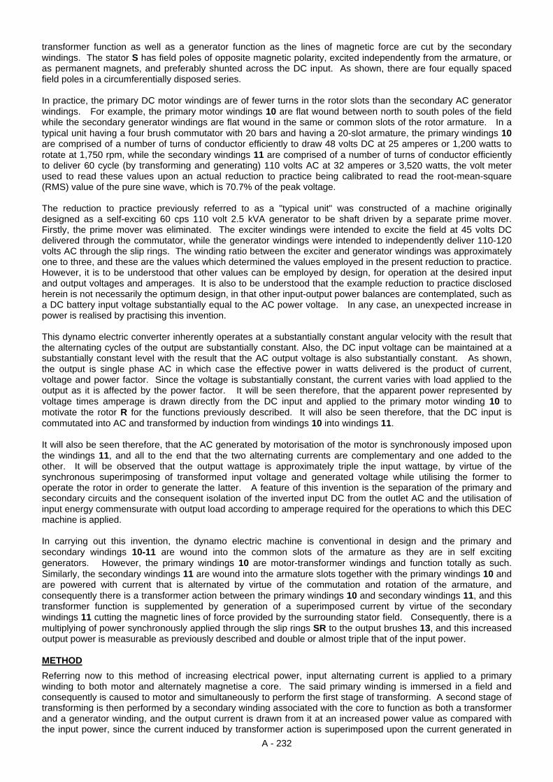
A - 232
transformer function as well as a generator function as the lines of magnetic force are cut by the secondary windings. The stator S has field poles of opposite magnetic polarity, excited independently from the armature, or as permanent magnets, and preferably shunted across the DC input. As shown, there are four equally spaced field poles in a circumferentially disposed series. In practice, the primary DC motor windings are of fewer turns in the rotor slots than the secondary AC generator windings. For example, the primary motor windings 10 are flat wound between north to south poles of the field while the secondary generator windings are flat wound in the same or common slots of the rotor armature. In a typical unit having a four brush commutator with 20 bars and having a 20-slot armature, the primary windings 10 are comprised of a number of turns of conductor efficiently to draw 48 volts DC at 25 amperes or 1,200 watts to rotate at 1,750 rpm, while the secondary windings 11 are comprised of a number of turns of conductor efficiently to deliver 60 cycle (by transforming and generating) 110 volts AC at 32 amperes or 3,520 watts, the volt meter used to read these values upon an actual reduction to practice being calibrated to read the root-mean-square (RMS) value of the pure sine wave, which is 70.7% of the peak voltage. The reduction to practice previously referred to as a "typical unit" was constructed of a machine originally designed as a self-exciting 60 cps 110 volt 2.5 kVA generator to be shaft driven by a separate prime mover. Firstly, the prime mover was eliminated. The exciter windings were intended to excite the field at 45 volts DC delivered through the commutator, while the generator windings were intended to independently deliver 110-120 volts AC through the slip rings. The winding ratio between the exciter and generator windings was approximately one to three, and these are the values which determined the values employed in the present reduction to practice. However, it is to be understood that other values can be employed by design, for operation at the desired input and output voltages and amperages. It is also to be understood that the example reduction to practice disclosed herein is not necessarily the optimum design, in that other input-output power balances are contemplated, such as a DC battery input voltage substantially equal to the AC power voltage. In any case, an unexpected increase in power is realised by practising this invention. This dynamo electric converter inherently operates at a substantially constant angular velocity with the result that the alternating cycles of the output are substantially constant. Also, the DC input voltage can be maintained at a substantially constant level with the result that the AC output voltage is also substantially constant. As shown, the output is single phase AC in which case the effective power in watts delivered is the product of current, voltage and power factor. Since the voltage is substantially constant, the current varies with load applied to the output as it is affected by the power factor. It will be seen therefore, that the apparent power represented by voltage times amperage is drawn directly from the DC input and applied to the primary motor winding 10 to motivate the rotor R for the functions previously described. It will also be seen therefore, that the DC input is commutated into AC and transformed by induction from windings 10 into windings 11. It will also be seen therefore, that the AC generated by motorisation of the motor is synchronously imposed upon the windings 11, and all to the end that the two alternating currents are complementary and one added to the other. It will be observed that the output wattage is approximately triple the input wattage, by virtue of the synchronous superimposing of transformed input voltage and generated voltage while utilising the former to operate the rotor in order to generate the latter. A feature of this invention is the separation of the primary and secondary circuits and the consequent isolation of the inverted input DC from the outlet AC and the utilisation of input energy commensurate with output load according to amperage required for the operations to which this DEC machine is applied. In carrying out this invention, the dynamo electric machine is conventional in design and the primary and secondary windings 10-11 are wound into the common slots of the armature as they are in self exciting generators. However, the primary windings 10 are motor-transformer windings and function totally as such. Similarly, the secondary windings 11 are wound into the armature slots together with the primary windings 10 and are powered with current that is alternated by virtue of the commutation and rotation of the armature, and consequently there is a transformer action between the primary windings 10 and secondary windings 11, and this transformer function is supplemented by generation of a superimposed current by virtue of the secondary windings 11 cutting the magnetic lines of force provided by the surrounding stator field. Consequently, there is a multiplying of power synchronously applied through the slip rings SR to the output brushes 13, and this increased output power is measurable as previously described and double or almost triple that of the input power. METHOD Referring now to this method of increasing electrical power, input alternating current is applied to a primary winding to both motor and alternately magnetise a core. The said primary winding is immersed in a field and consequently is caused to motor and simultaneously to perform the first stage of transforming. A second stage of transforming is then performed by a secondary winding associated with the core to function as both a transformer and a generator winding, and the output current is drawn from it at an increased power value as compared with the input power, since the current induced by transformer action is superimposed upon the current generated in
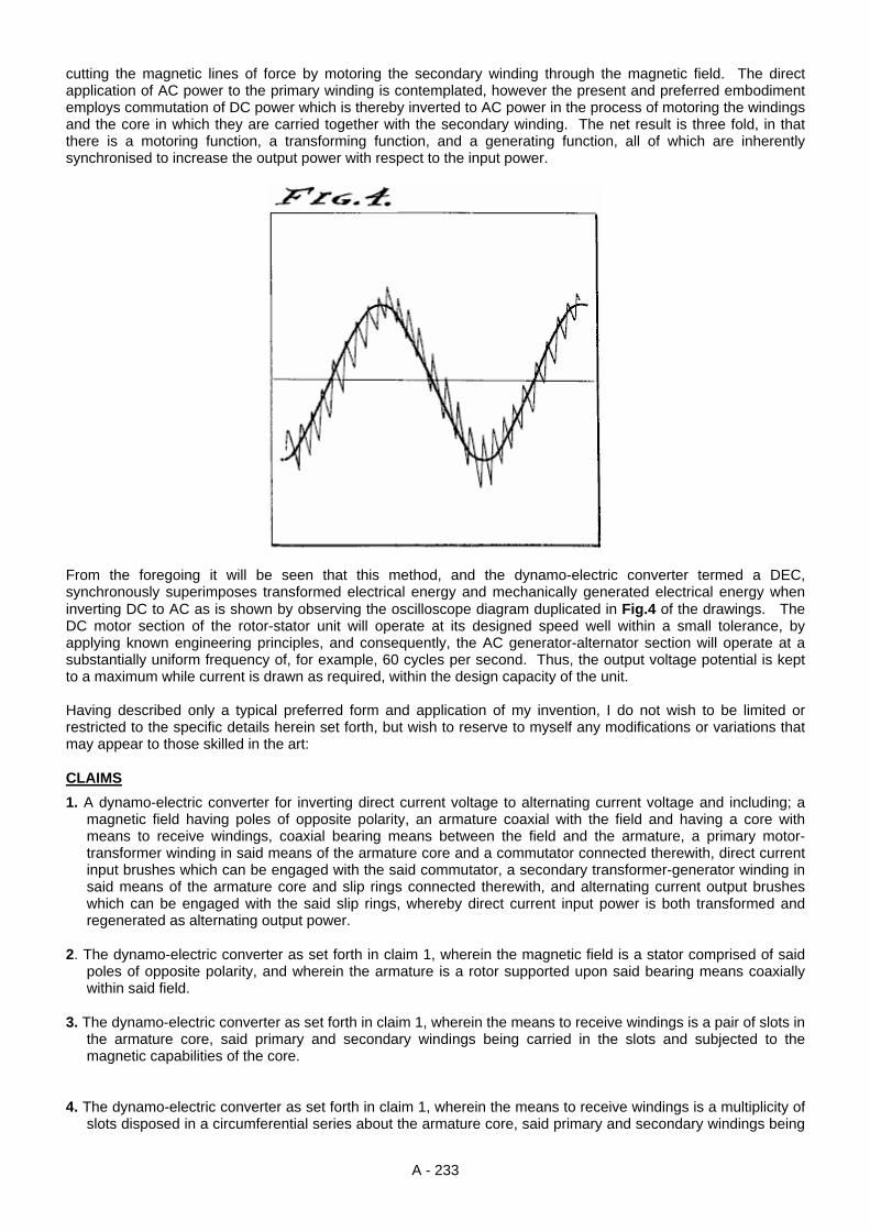
A - 233
cutting the magnetic lines of force by motoring the secondary winding through the magnetic field. The direct application of AC power to the primary winding is contemplated, however the present and preferred embodiment employs commutation of DC power which is thereby inverted to AC power in the process of motoring the windings and the core in which they are carried together with the secondary winding. The net result is three fold, in that there is a motoring function, a transforming function, and a generating function, all of which are inherently synchronised to increase the output power with respect to the input power.
From the foregoing it will be seen that this method, and the dynamo-electric converter termed a DEC, synchronously superimposes transformed electrical energy and mechanically generated electrical energy when inverting DC to AC as is shown by observing the oscilloscope diagram duplicated in Fig.4 of the drawings. The DC motor section of the rotor-stator unit will operate at its designed speed well within a small tolerance, by applying known engineering principles, and consequently, the AC generator-alternator section will operate at a substantially uniform frequency of, for example, 60 cycles per second. Thus, the output voltage potential is kept to a maximum while current is drawn as required, within the design capacity of the unit. Having described only a typical preferred form and application of my invention, I do not wish to be limited or restricted to the specific details herein set forth, but wish to reserve to myself any modifications or variations that may appear to those skilled in the art: CLAIMS
1. A dynamo-electric converter for inverting direct current voltage to alternating current voltage and including; a magnetic field having poles of opposite polarity, an armature coaxial with the field and having a core with means to receive windings, coaxial bearing means between the field and the armature, a primary motor-transformer winding in said means of the armature core and a commutator connected therewith, direct current input brushes which can be engaged with the said commutator, a secondary transformer-generator winding in said means of the armature core and slip rings connected therewith, and alternating current output brushes which can be engaged with the said slip rings, whereby direct current input power is both transformed and regenerated as alternating output power.
2. The dynamo-electric converter as set forth in claim 1, wherein the magnetic field is a stator comprised of said
poles of opposite polarity, and wherein the armature is a rotor supported upon said bearing means coaxially within said field.
3. The dynamo-electric converter as set forth in claim 1, wherein the means to receive windings is a pair of slots in
the armature core, said primary and secondary windings being carried in the slots and subjected to the magnetic capabilities of the core.
4. The dynamo-electric converter as set forth in claim 1, wherein the means to receive windings is a multiplicity of
slots disposed in a circumferential series about the armature core, said primary and secondary windings being
A - 234
circumferentially progressive windings respectively and carried in common slots respectively and subjected to the magnetic capabilities of the core.
5. The dynamo-electric converter as set forth in claim 1, wherein the magnetic field poles are permanent magnets. 6. The dynamo-electric converter as set forth in claim 1, wherein the magnetic field poles are electro magnets
energised separately from the said primary motor winding. 7. The dynamo-electric converter as set forth in claim 1, wherein the field poles are electro magnets energised in
parallel with the direct current input brushes which can be engaged with the commutator. 8. The dynamo-electric converter as set forth in claim 1, wherein the magnetic field is a stator comprised of said
poles of opposite polarity, wherein the armature is a rotor supported on said bearing means coaxially within said field, and wherein the means to receive windings is a pair of slots in the armature core, said primary and secondary windings being carried in the slots and subjected to the magnetic capabilities of the core.
9. The dynamo-electric converter as set forth in claim 1, wherein the magnetic field is a stator comprised of
permanent magnet poles of opposite polarity, wherein the armature is a rotor supported on said bearing means coaxially within said field, and wherein the means to receive windings is a pair of slots in the armature core, said primary and secondary windings being carried in the slots and subjected to the magnetic capabilities of the core.
10. The dynamo-electric converter as set forth in claim 1, wherein the magnetic field is a stator comprised of
permanent magnet poles of opposite polarity, wherein the armature is a rotor supported on said bearing means coaxially within said field, and wherein the means to receive windings is a multiplicity of slots disposed in a circumferential series about the armature core, said primary and secondary windings being circumferentially progressive windings and carried in common slots respectively and subjected to the magnetic capabilities of the core.
11. The dynamo-electric converter is set forth in claim 1, wherein the magnetic field poles are electro magnets of
opposite polarity energised in parallel with the direct current input brushes which can be engaged with the commutator, wherein the means to receive windings is a multiplicity of slots disposed in a circumferential series about the armature core, said primary and secondary windings being circumferentially progressive windings respectively and carried in common slots respectively and subjected to the magnetic capabilities of the core.
12. A method for increasing electrical power and comprised of; placing a primary winding within the flux of a
magnetic field and applying alternating current therethrough while motoring the same to revolve, simultaneously revolving a secondary winding with the primary winding and through a flux of a magnetic field, and simultaneously transforming the first mentioned alternating current from the primary winding and into the secondary winding while synchronously generating alternating current in the secondary winding.
13. The method of increasing electrical power as set forth in claim 12 wherein the magnetic field is held stationary
and the primary and secondary windings revolved together. 14. The method of increasing electrical power as set forth in claim 12 wherein the primary and secondary
windings are related to a common armature synchronously inducing into and generating electrical power through the secondary winding.
15. The method of increasing electrical power as set forth in claim 12 wherein the first mentioned alternating
current is commutated from direct current to alternating current by revolvement of said primary winding. 16. The method of increasing electrical power as set forth in claim 12 wherein the magnetic field is held stationary
and the primary and secondary windings revolved together and related to a common armature synchronously inducing into and generating electrical power through the secondary winding.
17. The method of increasing electrical power as set forth in claim 12 wherein the first mentioned alternating
current is commutated from direct current to alternating current by revolvement of said primary winding and the primary and secondary windings related to a common armature synchronously inducing into and generating electrical power through the secondary winding.
18. The method of increasing electrical power as set forth in claim 12 wherein the first mentioned alternating
current is commutated from direct current to alternating current by revolvement of said primary winding and wherein the magnetic field is held stationary and the primary and secondary windings revolved together and

A - 235
related to a common armature synchronously inducing into and generating electrical power through the secondary winding.
19. A dynamo-electric machine including; a first means applying a first alternating current into a primary motor-
transformer winding, and a second means inducing a second alternating current into a secondary transformer-generator winding, said secondary winding being carried by said second means to operate through a flux of a field and thereby generating a third alternating current, whereby said second and third alternating currents are synchronously superimposed one upon the other.
20. The dynamo-electric machine as set forth in claim 19 wherein the field is stationary and the primary and
secondary windings are rotary. 21. The dynamo-electric machine as set forth in claim 19 wherein the field is stationary and the primary and
secondary windings are rotary with commutator bars synchronously applying a direct current to motorise the armature and to apply said first alternating current thereto.
22. The dynamo-electric machine as set forth in claim 19 wherein the transformer means comprises magnetic
core means common to the primary and secondary windings. 23. The dynamo-electric machine as set forth in claim 19, wherein the field is stationary and the primary and
secondary windings are rotary with commutator bars synchronously applying a direct current to motorise the armature and to apply said first alternating current thereto, and wherein the transformer means comprises magnetic core means common to the primary and secondary windings.
24. A rotary dynamo-electric machine including: means applying alternating current through a primary motor-
transformer winding carried by an armature core carrying a secondary transformer-generator winding, a field, and bearing means for rotation of the armature core relative to the field, whereby the alternating current applied to the primary winding motors the armature and is transformed and an alternating current generated and superimposed thereon through the secondary winding for increased output power.
25. The rotary dynamo-electric machine as set forth in claim 24 wherein the primary and secondary windings are
each comprised of a number of turns of conductor to transform the first mentioned applied alternating current to the voltage of the alternating current generated through the secondary winding.
26. The rotary dynamo-electric motor as set forth in claim 24 wherein the first mentioned applied alternating
current is of different voltage than the increased output power and wherein the primary and secondary windings are each comprised of a number of turns of conductor to transform the first mentioned applied alternating current to the voltage of the alternating current generated through the secondary winding.
27. The rotary dynamo-electric machine as set forth in claim 24 wherein the first mentioned applied alternating
current is of lower voltage than the increased output power and wherein the primary and secondary windings are each comprised of a number of turns of conductor to transform the first mentioned applied alternating current to the voltage of the alternating current generated through the secondary winding.

A - 236
SHIGEAKI HAYASAKA: INDUCTION GENERATOR
Patent US 5,892,311 6th April 1996 Inventor: Shigeaki Hayasaka
INDUCTION GENERATOR HAVING A PAIR OF MAGNETIC POLES OF THE SAME POLARITY OPPOSED TO EACH OTHER WITH RESPECT TO A ROTATION SHAFT
This patent covers a device which is claimed to have a greater output power than the input power required to run it. ABSTRACT An induction generator having a pair of magnetic poles of the same polarity opposed to each other with respect to a rotation shaft is characterised by a high energy conversion efficiency. The induction generation has a rotation shaft driven by an external means; an even number of (more than three) stator cores provided to encircle the rotation shaft, predetermined gaps being provided between the adjacent stator cores; a first monopole rotor provided in the rotation shaft, surrounded by the even number of stator cores, and having first and second magnetic poles of the same polarity, the first and second magnetic poles being opposed to each other with respect to the rotation shaft in a cross section; a second monopole rotor provided in the rotation shaft so as to face the first monopole rotor at a predetermined distance along the rotation shaft, surrounded by the even number of stator cores, and having third and fourth magnetic poles of the same polarity opposite to the polarity of the first and second magnetic poles, the third and fourth magnetic poles being opposite to each other with respect to the rotation shaft; a plurality of windings provided in the even number of stator cores and connected according to a predetermined configuration. US Patent References: 282472 Jan., 1883 Delaporte 318 / 197. 2982872 May., 1961 Fredrickson 310 / 163. 3858308 Jan., 1975 Peterson 29 / 598. 4780635 Oct., 1988 Neumann 310 / 216. 5030867 Jul., 1991 Yamada et al. 310 / 156. 5111095 May., 1992 Hendershot 310 / 168. 5402025 Mar., 1995 Saito et al. 310 / 156. Other References: Publication "Novel Reluctance Machine Concepts for Variable Speed Drives", Lipo, T.A., Proceedings from the Mediterranean Electrochemical Conference, Ljubljana, May 22-24, 1991, pp. 34-43. DESCRIPTION TECHNICAL FIELD The present invention relates to an induction generator having a pair of magnetic poles of the same polarity opposed to each other with respect to a rotation shaft. Induction generators have been known as one type of electrical appliance from relatively old days and embodied in various forms adapted for individual applications. In addition to applications in power plants, ships and aircraft, induction generators convenient for household or leisure purposes have also been developed and used extensively. An induction generator converts kinetic energy into electric energy. Due to a necessity for improving efficiency of energy utilisation, there is a demand for a highly efficient energy conversion. BACKGROUND ART As is well known, an induction generator is operated on the principle that an electromotive force is induced in a coil, in proportion to the rate at which magnetic flux crosses that coil (Faraday's law of electromagnetic induction). According to Lenz's law, an induced electromotive force is generated in a direction in which a current that acts against a change in the magnetic flux is generated.
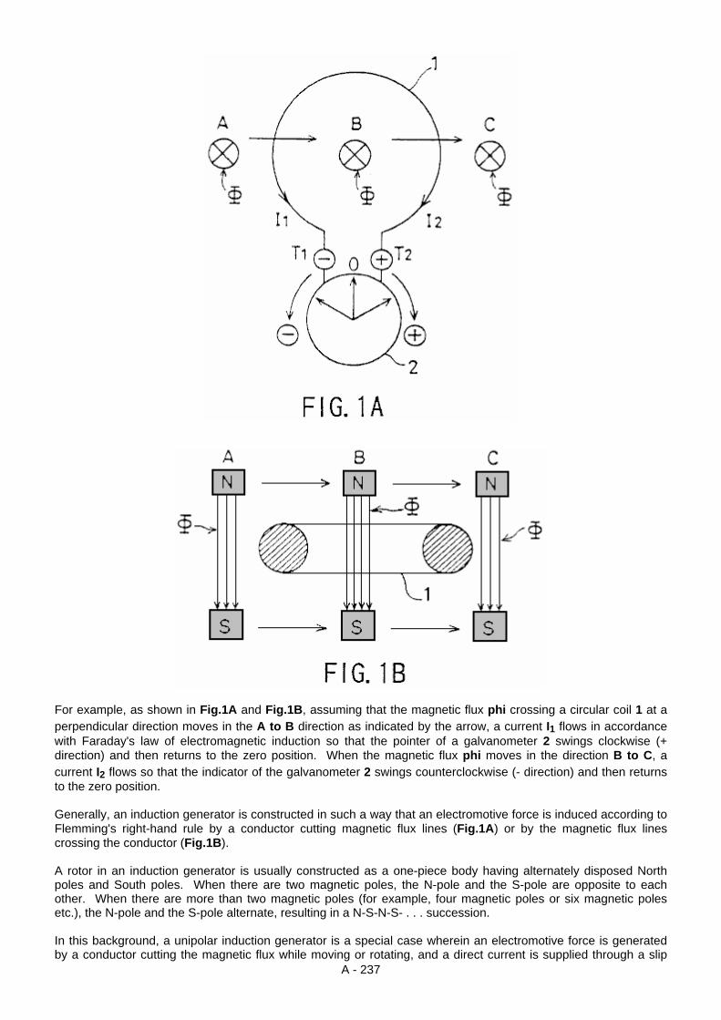
A - 237
For example, as shown in Fig.1A and Fig.1B, assuming that the magnetic flux phi crossing a circular coil 1 at a perpendicular direction moves in the A to B direction as indicated by the arrow, a current I1 flows in accordance with Faraday's law of electromagnetic induction so that the pointer of a galvanometer 2 swings clockwise (+ direction) and then returns to the zero position. When the magnetic flux phi moves in the direction B to C, a current I2 flows so that the indicator of the galvanometer 2 swings counterclockwise (- direction) and then returns to the zero position. Generally, an induction generator is constructed in such a way that an electromotive force is induced according to Flemming's right-hand rule by a conductor cutting magnetic flux lines (Fig.1A) or by the magnetic flux lines crossing the conductor (Fig.1B). A rotor in an induction generator is usually constructed as a one-piece body having alternately disposed North poles and South poles. When there are two magnetic poles, the N-pole and the S-pole are opposite to each other. When there are more than two magnetic poles (for example, four magnetic poles or six magnetic poles etc.), the N-pole and the S-pole alternate, resulting in a N-S-N-S- . . . succession. In this background, a unipolar induction generator is a special case wherein an electromotive force is generated by a conductor cutting the magnetic flux while moving or rotating, and a direct current is supplied through a slip

A - 238
ring. In other words, a unipolar induction motor is unique in its construction characterised by a non-alternating magnetic field travelling in the same direction. In the conventional induction generator such as the one described above, improvement in energy conversion efficiency is attained such that the rotor is constructed of a ferrite, or rare-earth, magnet characterised by a high energy product and a small reversing permeability (recoil permeability). Alternatively, the extent of demagnetisation due to generation of a counter magnetic field in an induction coil is reduced allowing the single polarity of the rotor to interact with the stator in forming a magnetic circuit. However, despite these measures, reduction in energy conversion efficiency due to a counter magnetic field of the rotor core, more specifically, due to demagnetisation resulting from the counter magnetic field caused by armature reaction presents a serious problem. The present invention has been developed in view of the above points, and its object is to provide an induction generator having a pair of magnetic poles of the same polarity opposed to each other with respect to a rotation shaft, wherein a high energy conversion efficiency is attained. DISCLOSURE OF THE INVENTION The present invention provides an induction generator having a pair of magnetic poles of the same polarity opposed to each other with respect to a rotation shaft, characterised by comprising: A rotation shaft driven by external means; An even number of (more than three) stator cores provided to encircle the rotation shaft, predetermined gaps being provided between the adjacent stator cores; A first single-opposed polarity rotor provided in the rotation shaft, surrounded by the even number of stator cores, and having first and second magnets magnetised such that the even number of stator cores remain facing a first polarity, the first and second magnets being opposed to each other with respect to the rotation shaft in a cross section; A second single-opposed-polarity rotor provided in the rotation shaft so as to face the first single-opposed-polarity rotor at a predetermined distance along the rotation shaft, surrounded by the even number of stator cores, and having third and fourth magnets magnetised such that the even number of stator cores remain facing a second polarity which is opposite to the polarity of the first polarity, the third and fourth magnets being disposed opposite to each other with respect to the rotation shaft; A plurality of windings provided in the even number of stator cores and connected according to a predetermined configuration, characterised in that: A rotating magnetic field which causes electromagnetic induction in the even number of stator cores successively is created by the first, second, third and fourth magnets when the first and second single-opposed-polarity rotors are rotated; and Periodic increase and decrease in the number of magnetic flux lines crossing a given winding and associated periodic decrease and increase crossing an adjacent winding causes a periodic electromotive force having a rectangular waveform to be output. In one aspect of the present invention, the plurality of windings connected according to the predetermined configuration form first and second serial circuits: The first serial circuit outputs a periodic first electromotive force having a rectangular waveform when a rotating magnetic field which causes electromagnetic induction in the even number of stator cores successively is created by the first, second, third and fourth magnets when the first and second single-opposed-polarity rotors are rotated; and The second serial circuit outputs a periodic second electromotive force of a rectangular waveform 1800. out of phase with the first electromotive force and having the same period as the first electromotive force, when a rotating magnetic field which causes electromagnetic induction in the even number of stator cores successively is created by the first and second single-opposed-polarity rotors are rotated. The induction generator of the present invention may also comprise:

A - 239
Rotation position detecting means for detecting a position of the first and second single-opposed-polarity rotors during their rotation; and Switching means which alternately causes positive components of the first electromotive force having a rectangular waveform and provided by the first serial circuit, or positive components of the second electromotive force having a rectangular waveform and provided by the second serial circuit to be output at intervals of an electrical angle of 1800. In another aspect of the present invention, the plurality of windings comprise a first winding provided in a first stator core of the even number of stator cores, a second winding provided in a second stator core adjacent to the first stator core so as to wind in a direction opposite to a direction in which the first winding is provided, a third winding provided in a third stator core adjacent to the second stator core so as to wind in the same direction as the first winding, a fourth winding provided in a fourth stator core adjacent to the third stator core so as to wind in a direction opposite to a direction in which the third winding is provided, the first through fourth windings being connected with each other according to a predetermined configuration. In still another aspect of the present invention, the first serial circuit comprises a first winding provided to wind in a first direction in a first stator core of the even number of stator cores, a second winding serially connected to the first winding and provided in a second stator core adjacent to the first stator core so as to wind in a second direction opposite to the first direction, a third winding serially connected with the second winding and provided in a third stator core adjacent to the second stator core so as to wind in the first direction, a fourth winding serially connected to the third winding and provided in a fourth stator core adjacent to the third stator core so as to wind in the second direction; and The second serial circuit comprises a fifth winding provided to wind in the second direction in the first stator core, a sixth winding serially connected to the fifth winding and provided in the second stator core so as to wind in the first direction, a seventh winding serially connected with the sixth winding and provided in the third stator core so as to wind in the second direction, an eighth winding serially connected to the seventh winding and provided in the fourth stator core so as to wind in the first direction. In yet another aspect of the present invention, the first through fourth magnets are arc-shaped; and the even number of stator cores have arc-shaped cross sections. In still another aspect of the present invention, the arc-shaped first through fourth magnets and the stator cores which have arc-like cross sections have an almost identical circumferential length. BRIEF DESCRIPTION OF THE DRAWINGS
Fig.1A and Fig.1B are diagrams explaining the principle of an induction generator; Fig.2A and Fig.2B are diagrams showing a first embodiment of the present invention; Fig.3A and Fig.3B are diagrams showing a single-opposed-polarity rotor 11N according to the first embodiment of the present invention; Fig.4A and Fig.4B are diagrams showing a single-opposed-polarity rotor 11S according to the first embodiment of the present invention; Fig.5A, Fig.5B and Fig.5C are diagrams showing how wirings are connected with each other according to the first embodiment of the present invention; Fig.6A is a diagram schematically showing how a rotating magnetic field according to the first embodiment crosses windings 7c-10c; Fig.6B shows a magnetic path; Fig.7 is a diagram showing a waveform of an output voltage according to the first embodiment; Fig.8A and Fig.8B are diagrams showing a second embodiment of the present invention; Fig.9 is a diagram showing how wirings are connected with each other according to a second embodiment; and
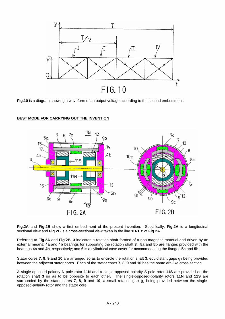
A - 240
Fig.10 is a diagram showing a waveform of an output voltage according to the second embodiment. BEST MODE FOR CARRYING OUT THE INVENTION
Fig.2A and Fig.2B show a first embodiment of the present invention. Specifically, Fig.2A is a longitudinal sectional view and Fig.2B is a cross-sectional view taken in the line 1B-1B' of Fig.2A. Referring to Fig.2A and Fig.2B, 3 indicates a rotation shaft formed of a non-magnetic material and driven by an external means; 4a and 4b bearings for supporting the rotation shaft 3; 5a and 5b are flanges provided with the bearings 4a and 4b, respectively; and 6 is a cylindrical case cover for accommodating the flanges 5a and 5b. Stator cores 7, 8, 9 and 10 are arranged so as to encircle the rotation shaft 3, equidistant gaps g1 being provided between the adjacent stator cores. Each of the stator cores 7, 8, 9 and 10 has the same arc-like cross section. A single-opposed-polarity N-pole rotor 11N and a single-opposed-polarity S-pole rotor 11S are provided on the rotation shaft 3 so as to be opposite to each other. The single-opposed-polarity rotors 11N and 11S are surrounded by the stator cores 7, 8, 9 and 10, a small rotation gap g0 being provided between the single-opposed-polarity rotor and the stator core.
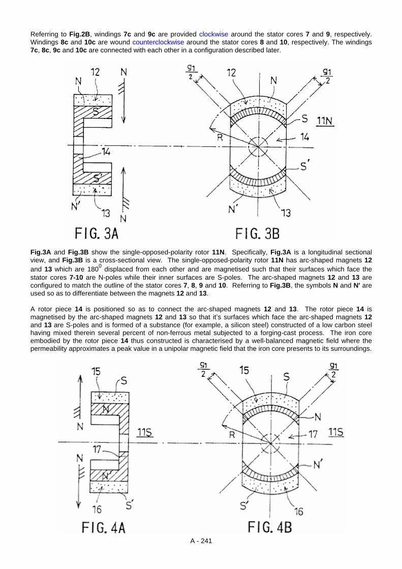
A - 241
Referring to Fig.2B, windings 7c and 9c are provided clockwise around the stator cores 7 and 9, respectively. Windings 8c and 10c are wound counterclockwise around the stator cores 8 and 10, respectively. The windings 7c, 8c, 9c and 10c are connected with each other in a configuration described later.
Fig.3A and Fig.3B show the single-opposed-polarity rotor 11N. Specifically, Fig.3A is a longitudinal sectional view, and Fig.3B is a cross-sectional view. The single-opposed-polarity rotor 11N has arc-shaped magnets 12 and 13 which are 1800 displaced from each other and are magnetised such that their surfaces which face the stator cores 7-10 are N-poles while their inner surfaces are S-poles. The arc-shaped magnets 12 and 13 are configured to match the outline of the stator cores 7, 8, 9 and 10. Referring to Fig.3B, the symbols N and N' are used so as to differentiate between the magnets 12 and 13. A rotor piece 14 is positioned so as to connect the arc-shaped magnets 12 and 13. The rotor piece 14 is magnetised by the arc-shaped magnets 12 and 13 so that it’s surfaces which face the arc-shaped magnets 12 and 13 are S-poles and is formed of a substance (for example, a silicon steel) constructed of a low carbon steel having mixed therein several percent of non-ferrous metal subjected to a forging-cast process. The iron core embodied by the rotor piece 14 thus constructed is characterised by a well-balanced magnetic field where the permeability approximates a peak value in a unipolar magnetic field that the iron core presents to its surroundings.
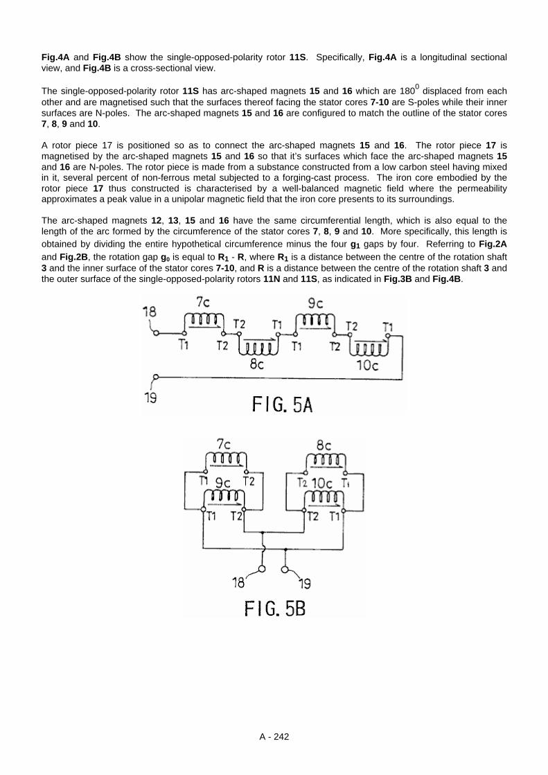
A - 242
Fig.4A and Fig.4B show the single-opposed-polarity rotor 11S. Specifically, Fig.4A is a longitudinal sectional view, and Fig.4B is a cross-sectional view. The single-opposed-polarity rotor 11S has arc-shaped magnets 15 and 16 which are 1800 displaced from each other and are magnetised such that the surfaces thereof facing the stator cores 7-10 are S-poles while their inner surfaces are N-poles. The arc-shaped magnets 15 and 16 are configured to match the outline of the stator cores 7, 8, 9 and 10. A rotor piece 17 is positioned so as to connect the arc-shaped magnets 15 and 16. The rotor piece 17 is magnetised by the arc-shaped magnets 15 and 16 so that it’s surfaces which face the arc-shaped magnets 15 and 16 are N-poles. The rotor piece is made from a substance constructed from a low carbon steel having mixed in it, several percent of non-ferrous metal subjected to a forging-cast process. The iron core embodied by the rotor piece 17 thus constructed is characterised by a well-balanced magnetic field where the permeability approximates a peak value in a unipolar magnetic field that the iron core presents to its surroundings. The arc-shaped magnets 12, 13, 15 and 16 have the same circumferential length, which is also equal to the length of the arc formed by the circumference of the stator cores 7, 8, 9 and 10. More specifically, this length is obtained by dividing the entire hypothetical circumference minus the four g1 gaps by four. Referring to Fig.2A and Fig.2B, the rotation gap g0 is equal to R1 - R, where R1 is a distance between the centre of the rotation shaft 3 and the inner surface of the stator cores 7-10, and R is a distance between the centre of the rotation shaft 3 and the outer surface of the single-opposed-polarity rotors 11N and 11S, as indicated in Fig.3B and Fig.4B.
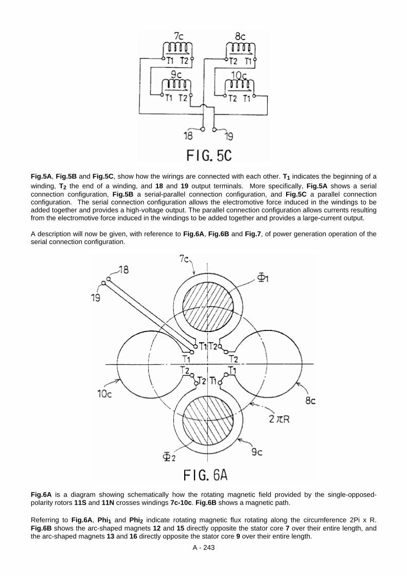
A - 243
Fig.5A, Fig.5B and Fig.5C, show how the wirings are connected with each other. T1 indicates the beginning of a winding, T2 the end of a winding, and 18 and 19 output terminals. More specifically, Fig.5A shows a serial connection configuration, Fig.5B a serial-parallel connection configuration, and Fig.5C a parallel connection configuration. The serial connection configuration allows the electromotive force induced in the windings to be added together and provides a high-voltage output. The parallel connection configuration allows currents resulting from the electromotive force induced in the windings to be added together and provides a large-current output. A description will now be given, with reference to Fig.6A, Fig.6B and Fig.7, of power generation operation of the serial connection configuration.
Fig.6A is a diagram showing schematically how the rotating magnetic field provided by the single-opposed-polarity rotors 11S and 11N crosses windings 7c-10c. Fig.6B shows a magnetic path. Referring to Fig.6A, Phi1 and Phi2 indicate rotating magnetic flux rotating along the circumference 2Pi x R. Fig.6B shows the arc-shaped magnets 12 and 15 directly opposite the stator core 7 over their entire length, and the arc-shaped magnets 13 and 16 directly opposite the stator core 9 over their entire length.

A - 244
As shown in Fig.6B, the magnetic flux Phi1 forms a magnetic path as follows: The rotor piece 14 (S) - the arc-shaped magnet pole 12 (N) - stator core 7 - the rotation gap g0 - the arc-shaped magnet 15 (S) - the rotor piece 17 (N). The magnetic flux Phi2 forms a magnetic path as follows: The rotor piece 14 (S) - the arc-shaped magnet 13 (N) - the rotation gap g0 - the stator core 9 - the rotation gap g0 - the arc-shaped magnet 16 (S) - the rotor piece 17 (N). Thus, a parallel magnetic path is formed. In this state, the magnetic flux Phi1 crosses the winding 7c, and the magnetic flux Phi2 crosses the winding 9c. A description focused on the rotation of the magnetic flux Phi1 is given. Specifically, a description will be given of a change in the way the magnetic flux Phi1 crosses the windings.

A - 245
Referring to a waveform of an output voltage shown in Fig.7, the entirety of the magnetic flux Phi1 crosses the winding 10c at a time t1. At a time t2, the entirety of the magnetic flux Phi1 crosses the winding 7c. At a time t3, the entirety of the magnetic flux Phi1 crosses the winding 8c. At a time t4, the entirety of the magnetic flux Phi1 crosses the winding 9c. At a time t5, the entirety of the magnetic flux Phi1 crosses the winding 10c. In this way, the magnetic flux Phi1 rotates at a constant speed during a time T, in a clockwise direction in Fig.6A. Between the time t1 and the time t2, an electromotive force having a descending triangular waveform, indicated by I in Fig.7, is generated in the winding 10c due to a decrease in the number of magnetic flux lines of the magnetic flux Phi crossing the winding 10c. An electromotive force having an ascending triangular waveform, indicated by I' in Fig.6, is generated in the winding 7c due to an increase in the number of magnetic flux lines of the magnetic flux Phi crossing the winding 7c. Accordingly, a positive rectangular waveform obtained by the sum of these triangular waveforms is output to the output terminals 18 and 19. Between the time t2 and the time t3, an electromotive force having an ascending triangular waveform, indicated by II in Fig.7, is generated in the winding 7c due to a decrease in the number of magnetic flux lines of the magnetic flux Phi crossing the winding 7c. An electromotive force having a descending triangular waveform, indicated by II' in Fig.7, is generated in the winding 8c due to an increase in the number of magnetic flux lines of the magnetic flux Phi crossing the winding 8c. Accordingly, a negative rectangular waveform obtained by the sum of these triangular waveforms is output to the output terminals 18 and 19. Between the time t3 and the time t4, an electromotive force having a descending triangular waveform, indicated by III in Fig.7, is generated in the winding 8c due to a decrease in the number of magnetic flux lines of the magnetic flux Phi of the magnetic flux Phi crossing the winding 8c. An electromotive force having an ascending triangular waveform, indicated by III' in Fig.7, is generated in the winding 9c due to an increase in the number of magnetic flux lines of the magnetic flux Phi crossing the winding 9c. Accordingly, a positive rectangular waveform obtained by the sum of these triangular waveforms is output to the output terminals 18 and 19. Between the time t4 and the time t5, an electromotive force having an ascending triangular waveform, indicated by IV in Fig.7, is generated in the winding 9c due to a decrease in the number of magnetic flux lines of the magnetic flux Phi crossing the winding 9c. An electromotive force having a descending triangular waveform, indicated by IV' in Fig.7, is generated in the winding 10c due to an increase in the number of magnetic flux lines of the magnetic flux Phi crossing the winding 10c. Accordingly, a negative rectangular waveform obtained by the sum of these triangular waveforms is output to the output terminals 18 and 19. While the magnetic flux Phi1 makes one rotation, an electromotive force having a synthesised rectangular waveform and a period of T/2 is output, as shown in Fig.7. Since the magnetic flux Phi2 also makes one rotation while the magnetic flux Phi1 makes one rotation and produces an output of an electromotive force having a similar rectangular waveform, the magnitude of the electromotive force obtained between the terminals 18 and 19 is actually double that indicated in Fig.7. In this way, this embodiment makes it possible to cancel a counter magnetic field and provide an induction generator having a pair of magnetic poles of the same polarity opposed to each other with respect to a rotation shaft and characterised by a high energy conversion efficiency. Our operating practice has confirmed that the generator having the construction of this embodiment provides an energy conversion efficiency which is high enough to require only 1/5.2 of the driving torque for the conventional generator.
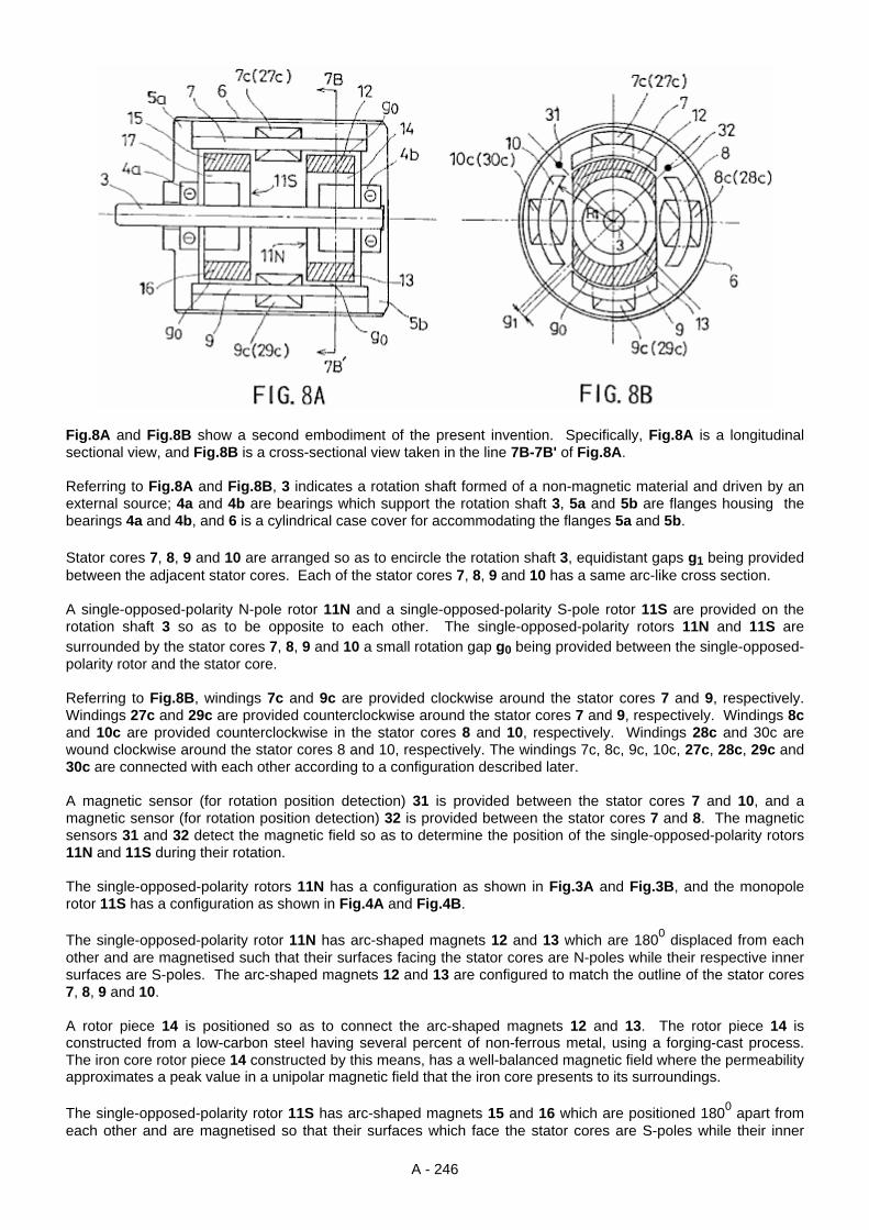
A - 246
Fig.8A and Fig.8B show a second embodiment of the present invention. Specifically, Fig.8A is a longitudinal sectional view, and Fig.8B is a cross-sectional view taken in the line 7B-7B' of Fig.8A. Referring to Fig.8A and Fig.8B, 3 indicates a rotation shaft formed of a non-magnetic material and driven by an external source; 4a and 4b are bearings which support the rotation shaft 3, 5a and 5b are flanges housing the bearings 4a and 4b, and 6 is a cylindrical case cover for accommodating the flanges 5a and 5b. Stator cores 7, 8, 9 and 10 are arranged so as to encircle the rotation shaft 3, equidistant gaps g1 being provided between the adjacent stator cores. Each of the stator cores 7, 8, 9 and 10 has a same arc-like cross section. A single-opposed-polarity N-pole rotor 11N and a single-opposed-polarity S-pole rotor 11S are provided on the rotation shaft 3 so as to be opposite to each other. The single-opposed-polarity rotors 11N and 11S are surrounded by the stator cores 7, 8, 9 and 10 a small rotation gap g0 being provided between the single-opposed-polarity rotor and the stator core. Referring to Fig.8B, windings 7c and 9c are provided clockwise around the stator cores 7 and 9, respectively. Windings 27c and 29c are provided counterclockwise around the stator cores 7 and 9, respectively. Windings 8c and 10c are provided counterclockwise in the stator cores 8 and 10, respectively. Windings 28c and 30c are wound clockwise around the stator cores 8 and 10, respectively. The windings 7c, 8c, 9c, 10c, 27c, 28c, 29c and 30c are connected with each other according to a configuration described later. A magnetic sensor (for rotation position detection) 31 is provided between the stator cores 7 and 10, and a magnetic sensor (for rotation position detection) 32 is provided between the stator cores 7 and 8. The magnetic sensors 31 and 32 detect the magnetic field so as to determine the position of the single-opposed-polarity rotors 11N and 11S during their rotation. The single-opposed-polarity rotors 11N has a configuration as shown in Fig.3A and Fig.3B, and the monopole rotor 11S has a configuration as shown in Fig.4A and Fig.4B. The single-opposed-polarity rotor 11N has arc-shaped magnets 12 and 13 which are 1800 displaced from each other and are magnetised such that their surfaces facing the stator cores are N-poles while their respective inner surfaces are S-poles. The arc-shaped magnets 12 and 13 are configured to match the outline of the stator cores 7, 8, 9 and 10. A rotor piece 14 is positioned so as to connect the arc-shaped magnets 12 and 13. The rotor piece 14 is constructed from a low-carbon steel having several percent of non-ferrous metal, using a forging-cast process. The iron core rotor piece 14 constructed by this means, has a well-balanced magnetic field where the permeability approximates a peak value in a unipolar magnetic field that the iron core presents to its surroundings. The single-opposed-polarity rotor 11S has arc-shaped magnets 15 and 16 which are positioned 1800 apart from each other and are magnetised so that their surfaces which face the stator cores are S-poles while their inner
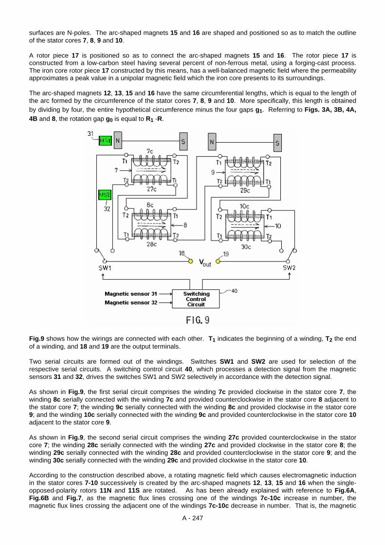
A - 247
surfaces are N-poles. The arc-shaped magnets 15 and 16 are shaped and positioned so as to match the outline of the stator cores 7, 8, 9 and 10. A rotor piece 17 is positioned so as to connect the arc-shaped magnets 15 and 16. The rotor piece 17 is constructed from a low-carbon steel having several percent of non-ferrous metal, using a forging-cast process. The iron core rotor piece 17 constructed by this means, has a well-balanced magnetic field where the permeability approximates a peak value in a unipolar magnetic field which the iron core presents to its surroundings. The arc-shaped magnets 12, 13, 15 and 16 have the same circumferential lengths, which is equal to the length of the arc formed by the circumference of the stator cores 7, 8, 9 and 10. More specifically, this length is obtained by dividing by four, the entire hypothetical circumference minus the four gaps g1. Referring to Figs. 3A, 3B, 4A, 4B and 8, the rotation gap g0 is equal to R1 -R.
Fig.9 shows how the wirings are connected with each other. T1 indicates the beginning of a winding, T2 the end of a winding, and 18 and 19 are the output terminals. Two serial circuits are formed out of the windings. Switches SW1 and SW2 are used for selection of the respective serial circuits. A switching control circuit 40, which processes a detection signal from the magnetic sensors 31 and 32, drives the switches SW1 and SW2 selectively in accordance with the detection signal. As shown in Fig.9, the first serial circuit comprises the winding 7c provided clockwise in the stator core 7, the winding 8c serially connected with the winding 7c and provided counterclockwise in the stator core 8 adjacent to the stator core 7; the winding 9c serially connected with the winding 8c and provided clockwise in the stator core 9; and the winding 10c serially connected with the winding 9c and provided counterclockwise in the stator core 10 adjacent to the stator core 9. As shown in Fig.9, the second serial circuit comprises the winding 27c provided counterclockwise in the stator core 7; the winding 28c serially connected with the winding 27c and provided clockwise in the stator core 8; the winding 29c serially connected with the winding 28c and provided counterclockwise in the stator core 9; and the winding 30c serially connected with the winding 29c and provided clockwise in the stator core 10. According to the construction described above, a rotating magnetic field which causes electromagnetic induction in the stator cores 7-10 successively is created by the arc-shaped magnets 12, 13, 15 and 16 when the single-opposed-polarity rotors 11N and 11S are rotated. As has been already explained with reference to Fig.6A, Fig.6B and Fig.7, as the magnetic flux lines crossing one of the windings 7c-10c increase in number, the magnetic flux lines crossing the adjacent one of the windings 7c-10c decrease in number. That is, the magnetic
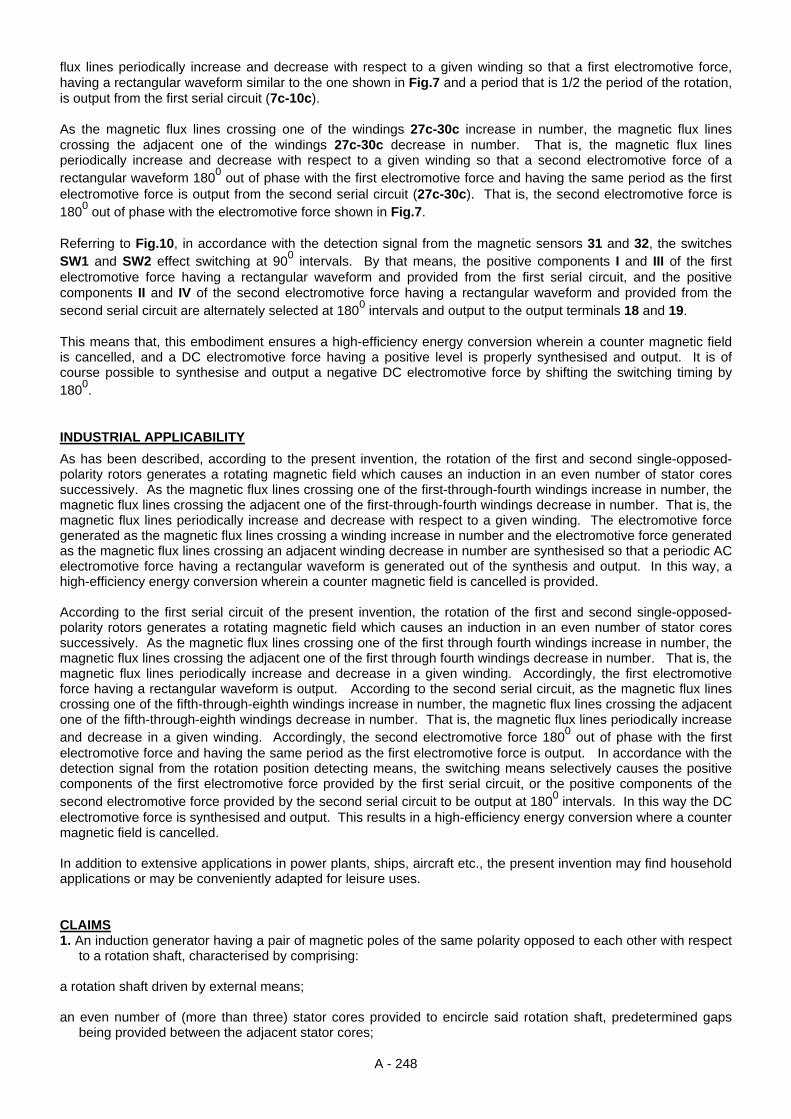
A - 248
flux lines periodically increase and decrease with respect to a given winding so that a first electromotive force, having a rectangular waveform similar to the one shown in Fig.7 and a period that is 1/2 the period of the rotation, is output from the first serial circuit (7c-10c). As the magnetic flux lines crossing one of the windings 27c-30c increase in number, the magnetic flux lines crossing the adjacent one of the windings 27c-30c decrease in number. That is, the magnetic flux lines periodically increase and decrease with respect to a given winding so that a second electromotive force of a rectangular waveform 1800 out of phase with the first electromotive force and having the same period as the first electromotive force is output from the second serial circuit (27c-30c). That is, the second electromotive force is 1800 out of phase with the electromotive force shown in Fig.7. Referring to Fig.10, in accordance with the detection signal from the magnetic sensors 31 and 32, the switches SW1 and SW2 effect switching at 900 intervals. By that means, the positive components I and III of the first electromotive force having a rectangular waveform and provided from the first serial circuit, and the positive components II and IV of the second electromotive force having a rectangular waveform and provided from the second serial circuit are alternately selected at 1800 intervals and output to the output terminals 18 and 19. This means that, this embodiment ensures a high-efficiency energy conversion wherein a counter magnetic field is cancelled, and a DC electromotive force having a positive level is properly synthesised and output. It is of course possible to synthesise and output a negative DC electromotive force by shifting the switching timing by 1800. INDUSTRIAL APPLICABILITY As has been described, according to the present invention, the rotation of the first and second single-opposed-polarity rotors generates a rotating magnetic field which causes an induction in an even number of stator cores successively. As the magnetic flux lines crossing one of the first-through-fourth windings increase in number, the magnetic flux lines crossing the adjacent one of the first-through-fourth windings decrease in number. That is, the magnetic flux lines periodically increase and decrease with respect to a given winding. The electromotive force generated as the magnetic flux lines crossing a winding increase in number and the electromotive force generated as the magnetic flux lines crossing an adjacent winding decrease in number are synthesised so that a periodic AC electromotive force having a rectangular waveform is generated out of the synthesis and output. In this way, a high-efficiency energy conversion wherein a counter magnetic field is cancelled is provided. According to the first serial circuit of the present invention, the rotation of the first and second single-opposed-polarity rotors generates a rotating magnetic field which causes an induction in an even number of stator cores successively. As the magnetic flux lines crossing one of the first through fourth windings increase in number, the magnetic flux lines crossing the adjacent one of the first through fourth windings decrease in number. That is, the magnetic flux lines periodically increase and decrease in a given winding. Accordingly, the first electromotive force having a rectangular waveform is output. According to the second serial circuit, as the magnetic flux lines crossing one of the fifth-through-eighth windings increase in number, the magnetic flux lines crossing the adjacent one of the fifth-through-eighth windings decrease in number. That is, the magnetic flux lines periodically increase and decrease in a given winding. Accordingly, the second electromotive force 1800 out of phase with the first electromotive force and having the same period as the first electromotive force is output. In accordance with the detection signal from the rotation position detecting means, the switching means selectively causes the positive components of the first electromotive force provided by the first serial circuit, or the positive components of the second electromotive force provided by the second serial circuit to be output at 1800 intervals. In this way the DC electromotive force is synthesised and output. This results in a high-efficiency energy conversion where a counter magnetic field is cancelled. In addition to extensive applications in power plants, ships, aircraft etc., the present invention may find household applications or may be conveniently adapted for leisure uses. CLAIMS 1. An induction generator having a pair of magnetic poles of the same polarity opposed to each other with respect
to a rotation shaft, characterised by comprising: a rotation shaft driven by external means; an even number of (more than three) stator cores provided to encircle said rotation shaft, predetermined gaps
being provided between the adjacent stator cores;
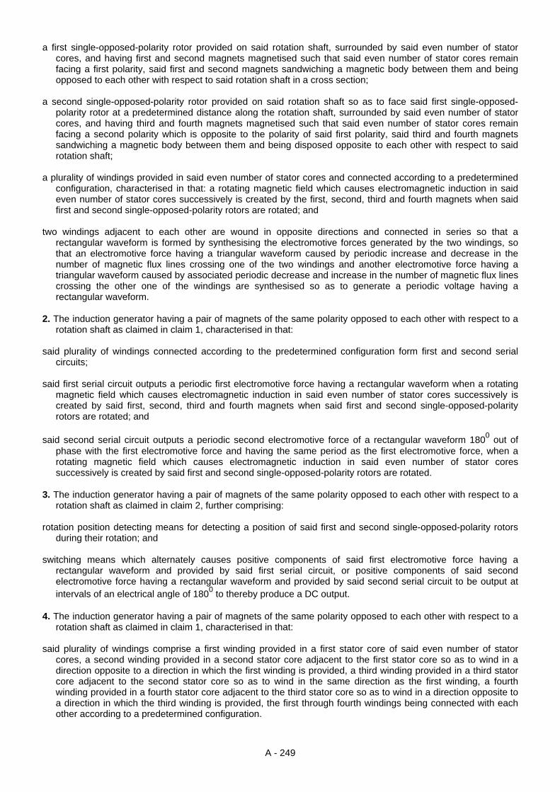
A - 249
a first single-opposed-polarity rotor provided on said rotation shaft, surrounded by said even number of stator cores, and having first and second magnets magnetised such that said even number of stator cores remain facing a first polarity, said first and second magnets sandwiching a magnetic body between them and being opposed to each other with respect to said rotation shaft in a cross section;
a second single-opposed-polarity rotor provided on said rotation shaft so as to face said first single-opposed-
polarity rotor at a predetermined distance along the rotation shaft, surrounded by said even number of stator cores, and having third and fourth magnets magnetised such that said even number of stator cores remain facing a second polarity which is opposite to the polarity of said first polarity, said third and fourth magnets sandwiching a magnetic body between them and being disposed opposite to each other with respect to said rotation shaft;
a plurality of windings provided in said even number of stator cores and connected according to a predetermined
configuration, characterised in that: a rotating magnetic field which causes electromagnetic induction in said even number of stator cores successively is created by the first, second, third and fourth magnets when said first and second single-opposed-polarity rotors are rotated; and
two windings adjacent to each other are wound in opposite directions and connected in series so that a
rectangular waveform is formed by synthesising the electromotive forces generated by the two windings, so that an electromotive force having a triangular waveform caused by periodic increase and decrease in the number of magnetic flux lines crossing one of the two windings and another electromotive force having a triangular waveform caused by associated periodic decrease and increase in the number of magnetic flux lines crossing the other one of the windings are synthesised so as to generate a periodic voltage having a rectangular waveform.
2. The induction generator having a pair of magnets of the same polarity opposed to each other with respect to a
rotation shaft as claimed in claim 1, characterised in that: said plurality of windings connected according to the predetermined configuration form first and second serial
circuits; said first serial circuit outputs a periodic first electromotive force having a rectangular waveform when a rotating
magnetic field which causes electromagnetic induction in said even number of stator cores successively is created by said first, second, third and fourth magnets when said first and second single-opposed-polarity rotors are rotated; and
said second serial circuit outputs a periodic second electromotive force of a rectangular waveform 1800 out of
phase with the first electromotive force and having the same period as the first electromotive force, when a rotating magnetic field which causes electromagnetic induction in said even number of stator cores successively is created by said first and second single-opposed-polarity rotors are rotated.
3. The induction generator having a pair of magnets of the same polarity opposed to each other with respect to a
rotation shaft as claimed in claim 2, further comprising: rotation position detecting means for detecting a position of said first and second single-opposed-polarity rotors
during their rotation; and switching means which alternately causes positive components of said first electromotive force having a
rectangular waveform and provided by said first serial circuit, or positive components of said second electromotive force having a rectangular waveform and provided by said second serial circuit to be output at intervals of an electrical angle of 1800 to thereby produce a DC output.
4. The induction generator having a pair of magnets of the same polarity opposed to each other with respect to a
rotation shaft as claimed in claim 1, characterised in that: said plurality of windings comprise a first winding provided in a first stator core of said even number of stator
cores, a second winding provided in a second stator core adjacent to the first stator core so as to wind in a direction opposite to a direction in which the first winding is provided, a third winding provided in a third stator core adjacent to the second stator core so as to wind in the same direction as the first winding, a fourth winding provided in a fourth stator core adjacent to the third stator core so as to wind in a direction opposite to a direction in which the third winding is provided, the first through fourth windings being connected with each other according to a predetermined configuration.

A - 250
5. The induction generator having a pair of magnets of the same polarity opposed to each other with respect to a rotation shaft as claimed in claim 2, characterised in that:
said first serial circuit comprise a first winding provided to wind in a first direction in a first stator core of said even
number of stator cores, a second winding serially connected to said first winding and provided in a second stator core adjacent to the first stator core so as to wind in a second direction opposite to the first direction, a third winding serially connected with said second winding and provided in a third stator core adjacent to the second stator core so as to wind in the first direction, a fourth winding serially connected to said third winding and provided in a fourth stator core adjacent to the third stator core so as to wind in the second direction; and
said second serial circuit comprises a fifth winding provided to wind in the second direction in said first stator core,
a sixth winding serially connected to said fifth winding and provided in said second stator core so as to wind in said first direction, a seventh winding serially connected with said sixth winding and provided in said third stator core so as to wind in said second direction, an eighth winding serially connected to said seventh winding and provided in said fourth stator core so as to wind in said first direction.
6. The induction generator having a pair of magnets of the same polarity opposed to each other with respect to a
rotation shaft as claimed in claim 1, characterised in that: said first through fourth magnets are arc-shaped; and said even number of stator cores have arc-shaped cross sections. 7. The induction generator having a pair of magnets of the same polarity opposed to each other with respect to a
rotation shaft as claimed in claim 6, characterised in that said arc-shaped first through fourth magnets and said stator cores which have arc-shaped cross sections have an almost identical circumferential length.
8. The induction generator having a pair of magnets of the same polarity opposed to each other with respect to a
rotation shaft as claimed in claim 2, characterised in that: said first through fourth magnets are arc-shaped; and said even number of stator cores have arc-shaped cross sections. 9. The induction generator having a pair of magnets of the same polarity opposed to each other with respect to a
rotation shaft as claimed in claim 3, characterised in that: said first through fourth magnets are arc-shaped; and said even number of stator cores have arc-shaped cross sections. 10. The induction generator having a pair of magnets of the same polarity opposed to each other with respect to a
rotation shaft as claimed in claim 4, characterised in that: said first through fourth magnets are arc-shaped; and said even number of stator cores have arc-shaped cross sections. 11. The induction generator having a pair of magnetic poles of the same polarity opposed to each other with
respect to a rotation shaft as claimed in claim 5, characterised in that: said first through fourth magnets are arc-shaped; and said even number of stator cores have arc-shaped cross sections. 12. The induction generator having a pair of magnetic poles of the same polarity opposed to each other with
respect to a rotation shaft as claimed in claim 8, characterised in that said arc-shaped first through fourth magnets and said stator cores which have arc-shaped cross sections have an almost identical circumferential length.
13. The induction generator having a pair of magnetic poles of the same polarity opposed to each other with
respect to a rotation shaft as claimed in claim 9, characterised in that said arc-shaped first through fourth magnets and said stator cores which have arc-shaped cross sections have an almost identical circumferential length.

A - 251
14. The induction generator having a pair of magnetic poles of the same polarity opposed to each other with
respect to a rotation shaft as claimed in claim 10, characterised in that said arc-shaped first through fourth magnets and said stator cores which have arc-shaped cross sections have an almost identical circumferential length.
15. The induction generator having a pair of magnetic poles of the same polarity opposed to each other with
respect to a rotation shaft as claimed in claim 11, characterised in that said arc-shaped first through fourth magnets and said stator cores which have arc-shaped cross sections have an almost identical circumferential length.

A - 252
LARRY JAMISON: ELECTRICAL ENERGISER
Patent Application EU 82,400,992.2 22nd December 1982 Inventor: Larry T. Jamison
ENERGY SOURCE EMPLOYING ELECTRICAL ENERGISER This patent application shows the details of a device which it is claimed, can produce electricity without the need for any fuel. It should be noted that while construction details are provided which imply that the inventor constructed and tested several of these devices, this is only an application and not a granted patent. ABSTRACT An energy producing system is provided which produces energy for use, for example, in an electric vehicle or in a home power plant. The system includes an electrical energiser (60) including a double-wound rotor and a double-wound stator, for producing electrical energy which is stored in the system, e.g. in a battery (66) storage arrangement, which provides initial energisation of the system. the stored energy is supplied to an electric motor (68) which drives the energiser (60) to thereby create additional energy. the energiser is able to supply the needs of the system as well as to power a load. BACKGROUND OF THE INVENTION The present invention relates to energy producing systems and, more particularly, to an electrical energiser-motor system for providing energy, e.g., for an automotive vehicle or as part of a home energy plant. With the advent of the so-called “energy crisis” and the consequent search for alternative energy sources to substitute for oil, considerable attention has been focused on automotive vehicles as chief users of oil products. One aspect of this search has fostered renewed interest in electrically driven vehicles such as electric cars and the like. A principal shortcoming of prior-art electrical vehicles has been the need to recharge the batteries which provide the power for the electrical motor drive system. The present invention overcomes this problem through the provision of an electrical energiser-motor system which produces more energy than is expended, thereby enabling the excess energy to be stored in the battery system, to be drawn upon as required. Thus, the need for recharging of the batteries associated with conventional electrical vehicles is eliminated with the system of this invention. It should be noted that while the system of the invention has enormous potential in connection with its use in electrical vehicles, the system is clearly not limited to such use and would obviously be advantageous when used, for example, as the energy source for a home energy plant, as well as in many other applications. In accordance with the invention, and energy producing system of the type described above is provided which comprises and electrical “energiser” comprising at least one double-wound stator and at least one double-wound shaft-mounted rotor located within a housing, electrical energy being collected from the rotor through a suitable electrical take-off device and being available for utilisation by the system, and an electric motor, powered by the energiser for driving the rotor shaft of the energiser. A battery arrangement is initially used to supply energy to the system and, as stated above, the excess energy generated by the energiser over and above that required by the system and the system load, is stored through charging of the batteries. The motor includes an armature with a plurality of winding slots in it and a plurality of windings being wound into two circumferentially spaced slots in the armature, i.e. such a winding is wound through a first slot (e.g. slot 1) and returned through a second spaced slot (e.g. slot 5). depending on the energy demands, the energiser may include a pair of stators and rotors, with the rotors being mounted on a common shaft. The motor is preferably energised through an arrangement of a commutator and plural brushes, while a slip ring and associated brushes connected to an output bridge circuit form the energy take-off for the energiser. Other features and advantages of the invention will be shown in the detailed description of the preferred embodiments which follows.
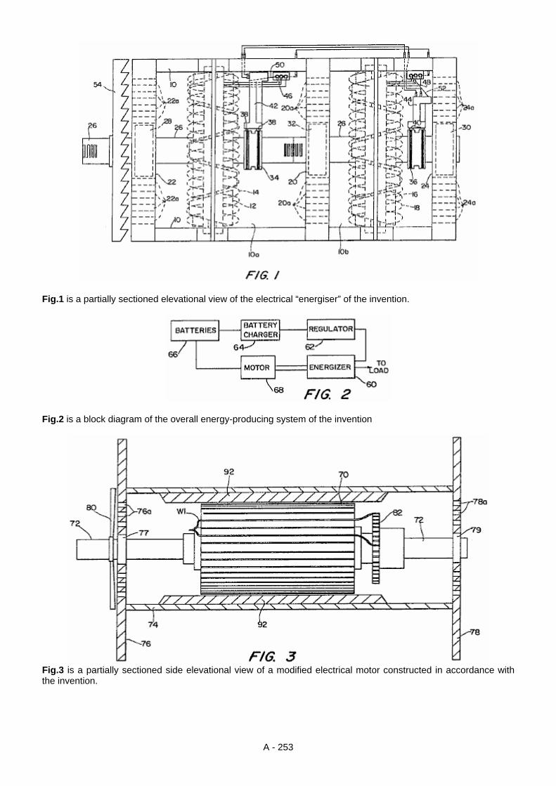
A - 253
Fig.1 is a partially sectioned elevational view of the electrical “energiser” of the invention.
Fig.2 is a block diagram of the overall energy-producing system of the invention
Fig.3 is a partially sectioned side elevational view of a modified electrical motor constructed in accordance with the invention.

A - 254
Fig.4 is an exploded perspective view of the basic components of the motor of Fig.3.
Fig.5 is an end view of the brush holder also illustrated in Fig.4.
Fig.6 and Fig.7 show details of the winding pattern of the motor of Fig.3.
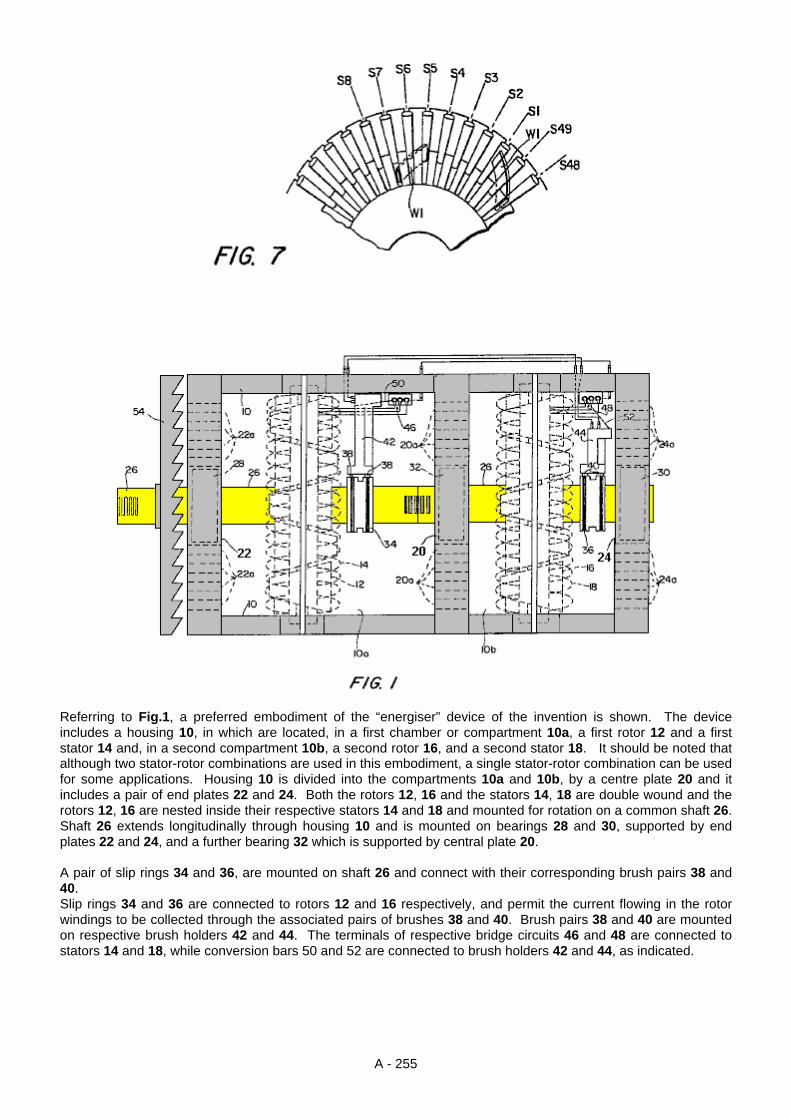
A - 255
Referring to Fig.1, a preferred embodiment of the “energiser” device of the invention is shown. The device includes a housing 10, in which are located, in a first chamber or compartment 10a, a first rotor 12 and a first stator 14 and, in a second compartment 10b, a second rotor 16, and a second stator 18. It should be noted that although two stator-rotor combinations are used in this embodiment, a single stator-rotor combination can be used for some applications. Housing 10 is divided into the compartments 10a and 10b, by a centre plate 20 and it includes a pair of end plates 22 and 24. Both the rotors 12, 16 and the stators 14, 18 are double wound and the rotors 12, 16 are nested inside their respective stators 14 and 18 and mounted for rotation on a common shaft 26. Shaft 26 extends longitudinally through housing 10 and is mounted on bearings 28 and 30, supported by end plates 22 and 24, and a further bearing 32 which is supported by central plate 20. A pair of slip rings 34 and 36, are mounted on shaft 26 and connect with their corresponding brush pairs 38 and 40. Slip rings 34 and 36 are connected to rotors 12 and 16 respectively, and permit the current flowing in the rotor windings to be collected through the associated pairs of brushes 38 and 40. Brush pairs 38 and 40 are mounted on respective brush holders 42 and 44. The terminals of respective bridge circuits 46 and 48 are connected to stators 14 and 18, while conversion bars 50 and 52 are connected to brush holders 42 and 44, as indicated.

A - 256
A cooling fan 54, is also mounted on shaft 26 and a plurality of apertures 201, 22a and 24a are provided in centre plate 20 and end plates 22 and 24, to promote cooling of the device. The energiser of Fig.1 is preferably incorporated in a system such as shown in a highly schematic manner in Fig.2 where the output of the energiser is used to supply the energy for driving a motor. To this end, the energiser, which is denoted by 60 in Fig.2, is connected through a regulator 62, to battery charger 64 for batteries 66 connected to a motor 68. These batteries 66 are used to provide the initial energisation of the system as well as to store energy produced by the energiser 60. It will be understood that the energiser 60 provides energy enough to power motor 68 (which, in turn, drives energiser 60 through rotation of shaft 26) as well as to provide storage for energy in the system. It will also be appreciated that the system illustrated schematically in Fig.2 includes suitable controls (switches, rheostats, sensors, etc.) to provide initial energisation as well as appropriate operational control of the system.
In a preferred embodiment, motor 68 is of the form shown in Fig.3. As illustrated, the motor is of a generally conventional form (with exceptions noted below) and comprises an armature 70, mounted on a shaft 72 within housing 74. Housing 74 includes a pair of end plates 76 and 78, which mount shaft bearings 77 and 79. Apertures 76a and 78a are provided in end plates 76 and 78 and a cooling fan 80 is mounted on shaft 72 to provide cooling.

A - 257
A commutator 82 is also mounted on shaft 72, and co-operates with associated brushes (not shown in Fig.1), to conduct current to the windings of armature 70. This co-operation is shown best in Fig.4 which is an exploded view, illustrating the armature 70, commutator 82 and a brush holder 84.
As shown in Fig.5, the brush holder 84 includes eight brush mounts 86, each of which defines a slot 88 in which a pair of brushes is mounted. One brush 90 is shown in Fig.5, it being understood that two such brushes are mounted in each slot 88 so that sixteen brushes are required. The motor of Fig.3 to Fig.6 includes eight pole shoes (not shown) which are secured to housing 74 and which serve to mount eight field coils or windings 92 (see Fig.3 and Fig.4) spaced out around the periphery of armature 72. An important feature of the motor of Fig.3 to Fig.6 concerns the manner in which the windings for armature 70 are wound. As illustrated in Fig.3, Fig.6 and Fig.7, a typical winding W1 is wound in two slots, with the illustrated winding being doubled back and continuing from armature slot S1 to armature slot S5 (see Fig.3 and Fig.6). Similarly, the winding in slot S2 continues to slot S6, the winding of slot S3 continues to slot S7, and so on for the forty-nine windings. In a specific preferred embodiment, the motor described above is a 48-volt, 412 horsepower motor having a top operating speed of 7,000 rpm. A rheostat control (not shown) is used to control the input voltage and, as discussed above, the motor is powered from the energiser of Fig.1. It will be appreciated that the energy take-off from the system is preferably from the output shaft of the motor, although the electrical energy may also be tapped off from the energiser output. Although the invention has been described in relation to exemplary embodiments, it will be understood by those skilled in the art, that variations and modifications can be effected in these embodiments without departing from the scope and spirit of the invention. CLAIMS
1. An energy-producing system providing an output for utilisation by a utilising device, the system comprising:
An electrical energising means comprising a housing (10); at least one double-wound stator (14 or 18) located within the housing; at least one double-wound rotor (12 or 16) located within the housing; a rotor shaft (26), supported in the housing, and on which the double-wound rotor is mounted; and an energy take-off mechanism (34 or 36) including a mechanism for collecting electrical energy from the rotor, mounted on the shaft and connected to the rotor, the mechanism having at least one stationary output. A motor (68), including a connection to the electrical energiser through which to draw the power to operate the motor and drive the rotor shaft of the energiser, the motor having an armature (70) with a plurality of winding slots (S1 to S49) in it, and a plurality of windings (W1) wound in those slots, at least some of the windings being wound in two slots spaced out around the circumference of the armature (for example, S1 and S5), and an energy supply mechanism (66) for supplying electrical energy to the motor at least during initial energisation of the motor, and connected to the energiser for supplying energy to the motor during its operation.
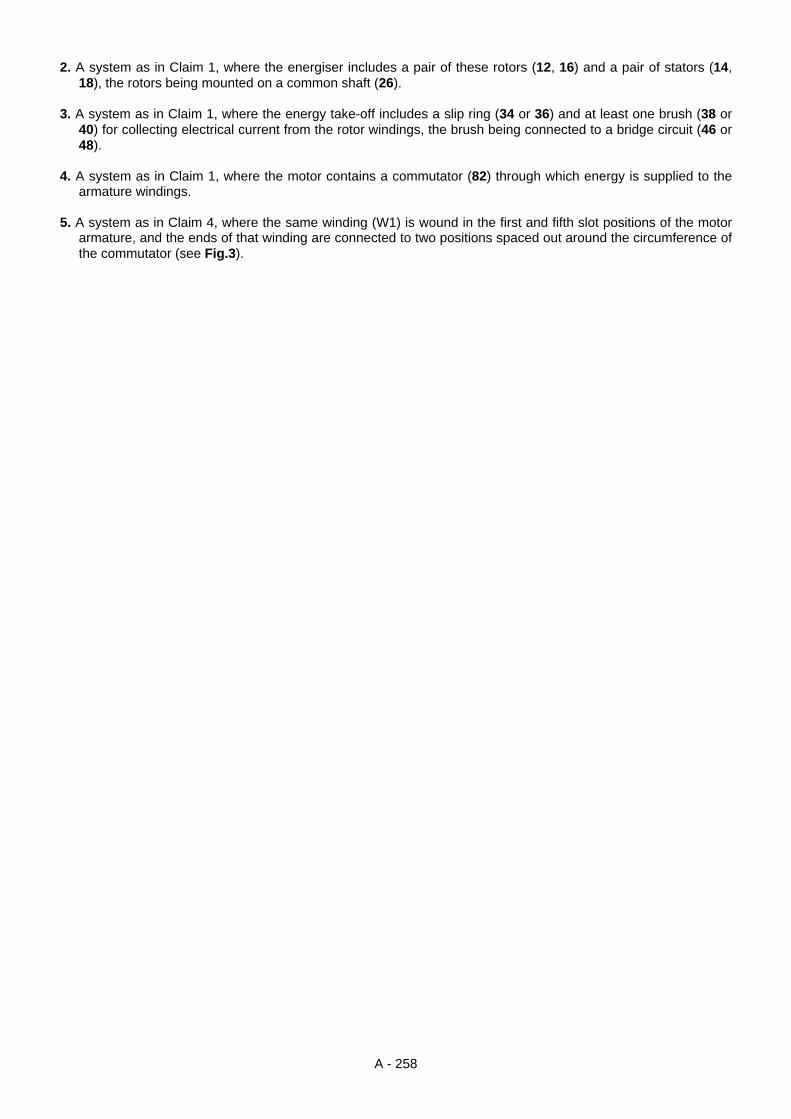
A - 258
2. A system as in Claim 1, where the energiser includes a pair of these rotors (12, 16) and a pair of stators (14, 18), the rotors being mounted on a common shaft (26).
3. A system as in Claim 1, where the energy take-off includes a slip ring (34 or 36) and at least one brush (38 or
40) for collecting electrical current from the rotor windings, the brush being connected to a bridge circuit (46 or 48).
4. A system as in Claim 1, where the motor contains a commutator (82) through which energy is supplied to the
armature windings. 5. A system as in Claim 4, where the same winding (W1) is wound in the first and fifth slot positions of the motor
armature, and the ends of that winding are connected to two positions spaced out around the circumference of the commutator (see Fig.3).
A - 259
TERUO KAWAI: ELECTRIC MOTOR
United States Patent 5,436,518 25th July 1995 Inventor: Teruo Kawai
MOTIVE POWER-GENERATING DEVICE Please note that this is a re-worded excerpt from this patent. It describes a motor which has an output power greater than its input power. SUMMARY OF THE INVENTION It is an object of the invention to provide a motive power generation device in which the occurrence of a force acting in a direction opposite to the direction of movement of a rotor and/or a stator is prevented, so as to permit efficient use of electric energy to be applied to electromagnets, as well as magnetic energy generated by a permanent magnet. In order to achieve the above object, the first invention comprises a permanent magnet disposed around a rotational output shaft which is mounted on a bearing, a magnetic body positioned concentrically with the permanent magnet for rotation with the output shaft, the magnetic body being subjected to the magnetic flux of the permanent magnet, a plurality of electromagnets permanently mounted on the support member so that they are spaced a predetermined distance around the periphery of the magnetic material, each magnetic circuit of the electromagnets being independent of one another and the excitation change-over mechanism of the electromagnets which can sequentially magnetise one of the electromagnets which is positioned forward, with regard to a rotational direction, of the output shaft, so as to impart to the electromagnet a magnetic polarity magnetically opposite to that of the magnetic pole of the permanent magnet, whereby a magnetic flux passing through the magnetic body converges in one direction thereby applying a rotational torque to the output shaft. According to the first invention, when one of the electromagnets which is positioned ahead in the rotational direction of the rotational output shaft, a magnetic field created by the excited electromagnet and a magnetic field created by the permanent magnet interact with each other. Thus, the magnetic flux passing through the magnetic body converges toward the exited electromagnet, so as to rotate the rotational output shaft by a predetermined angle toward the excited electromagnet. When the rotational output shaft has been rotated by the predetermined angle, the above excited electromagnet is de-magnetised, and another electromagnet currently positioned ahead with respect to the rotational direction of the rotor output shaft is excited or magnetised. Sequential excitation of the electromagnets in the above manner permits rotation of the output shaft in a predetermined direction. In this regard, it should be noted that the electromagnets are excited so as to have a magnetic polarity opposite to that of the magnetic pole of the permanent magnet and that the magnetic circuit of the excited electromagnets is independent from those of adjacent electromagnets. Thus, the magnetic flux generated by the excited electromagnet is prevented from passing through magnetic circuits of adjacent electromagnets, which, if it occurs, might cause the electromagnets to be magnetised to have the same polarity as that of the magnetic pole of the permanent magnet. Accordingly, no objectionable force will be generated which might interfere with rotation of the output shaft. In order to achieve the above object, the second invention comprises a permanent magnet mounted on a movable body arranged movably along a linear track, a magnetic body mounted on the permanent magnet, the magnetic body being subjected to a magnetic flux of the permanent magnet, a plurality of electromagnets spaced an appropriate distance along the linear track, the electromagnets having magnetic circuits which are independent of one another and the excitation mechanism arranged to magnetise each of the electromagnets sequentially when each is positioned forward of the movable body, (with respect to the direction of movement) so as to impart to the excited electromagnet a magnetic polarity opposite to that of the magnetic pole of the permanent magnet, whereby a magnetic flux passing through the magnetic body converges in a predetermined direction so as to cause linear movement of the movable body. According to the second invention, when the electromagnet positioned ahead of the forward end of the movable body with regard to the direction of the movement of the movable body is excited, a magnetic field generated by the excited electromagnet and magnetic field generated by the permanent magnet interact with each other. Thus, a magnetic flux passing through the magnetic body converges toward the excited electromagnet, so as to displace the movable body a predetermined distance toward the excited electromagnet. When the movable body has been moved the predetermined distance, the movable body is positioned below the above excited electromagnet, and another electromagnet is positioned ahead of the forward end of the movable body. When this occurs, excitation of the electromagnet positioned above the movable body is interrupted, and excitation of the electromagnet now positioned ahead of the forward end of the movable body is initiated. Sequential excitation of
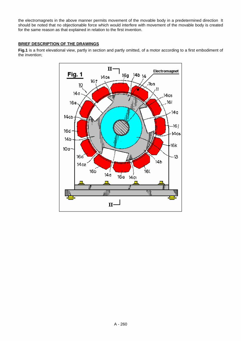
A - 260
the electromagnets in the above manner permits movement of the movable body in a predetermined direction It should be noted that no objectionable force which would interfere with movement of the movable body is created for the same reason as that explained in relation to the first invention. BRIEF DESCRIPTION OF THE DRAWINGS Fig.1 is a front elevational view, partly in section and partly omitted, of a motor according to a first embodiment of the invention;

A - 261
Fig.2 is a sectional view along line II--II in Fig.1;
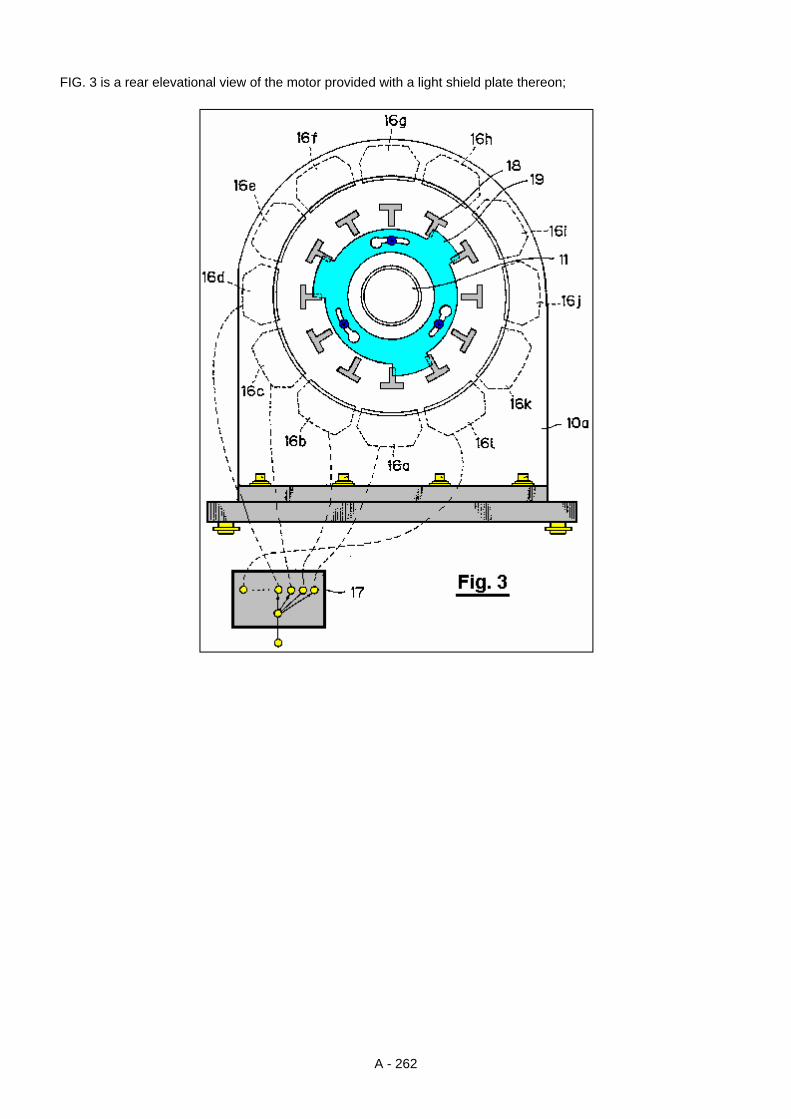
A - 262
FIG. 3 is a rear elevational view of the motor provided with a light shield plate thereon;
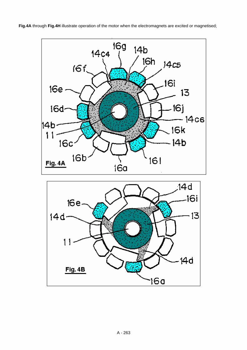
A - 263
Fig.4A through Fig.4H illustrate operation of the motor when the electromagnets are excited or magnetised;
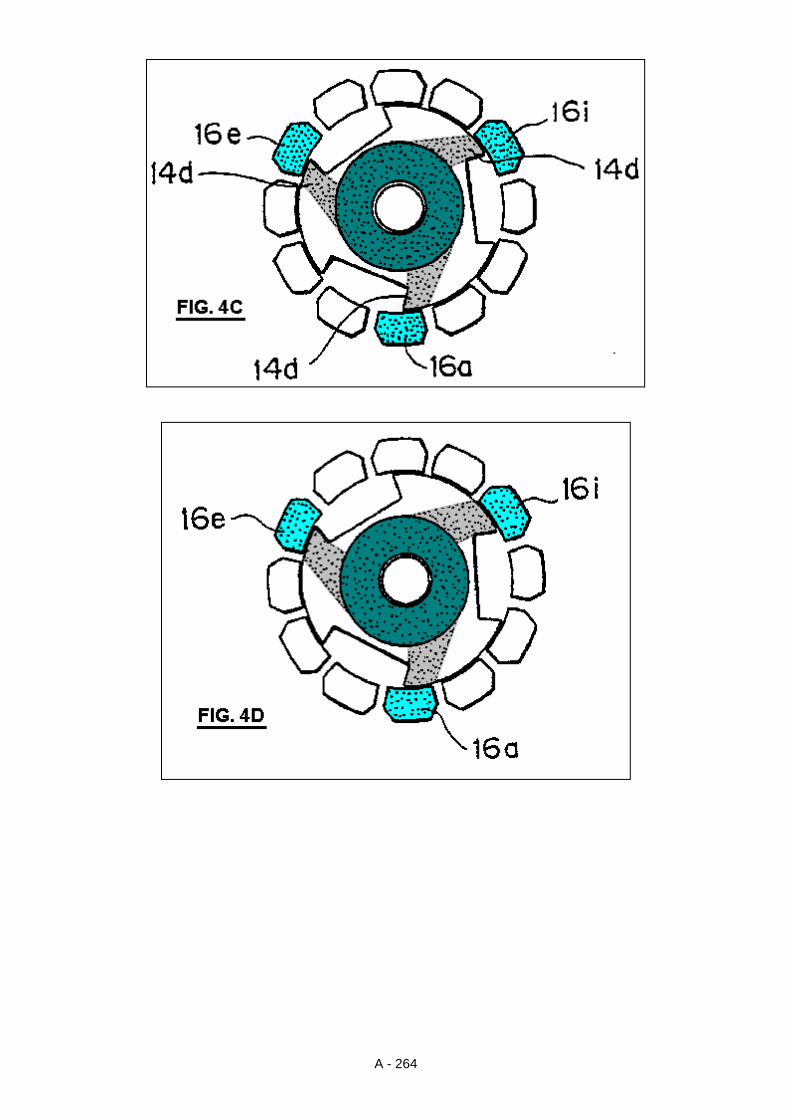
A - 264
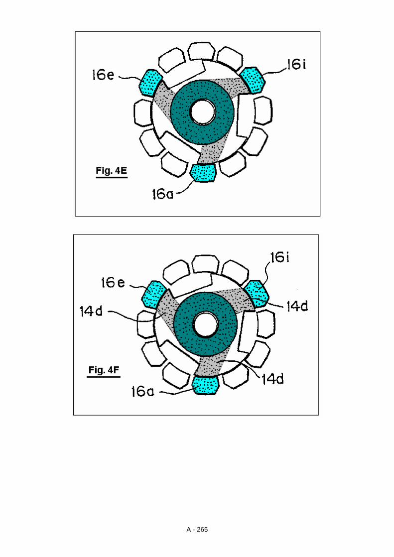
A - 265
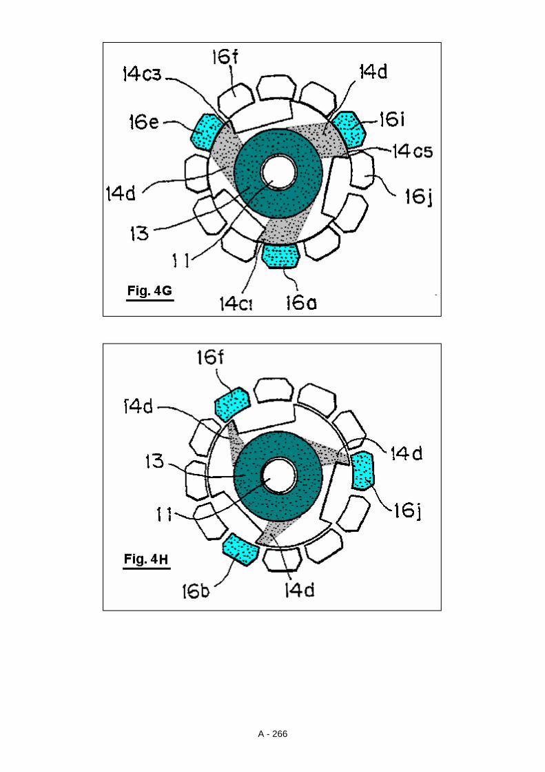
A - 266
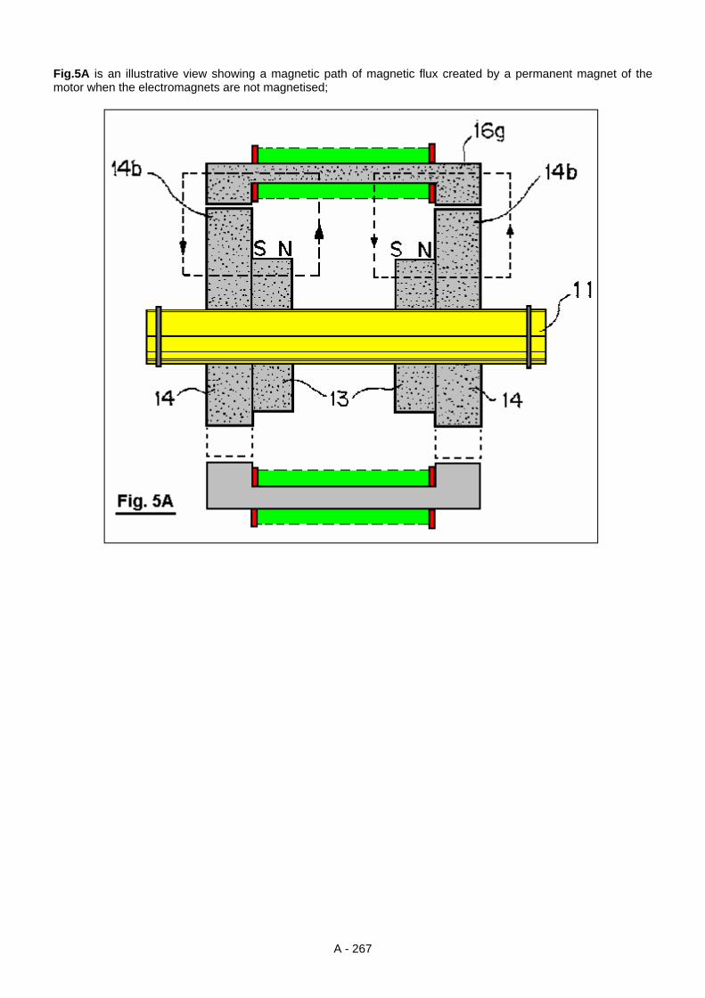
A - 267
Fig.5A is an illustrative view showing a magnetic path of magnetic flux created by a permanent magnet of the motor when the electromagnets are not magnetised;
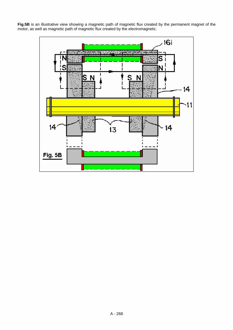
A - 268
Fig.5B is an illustrative view showing a magnetic path of magnetic flux created by the permanent magnet of the motor, as well as magnetic path of magnetic flux created by the electromagnets;
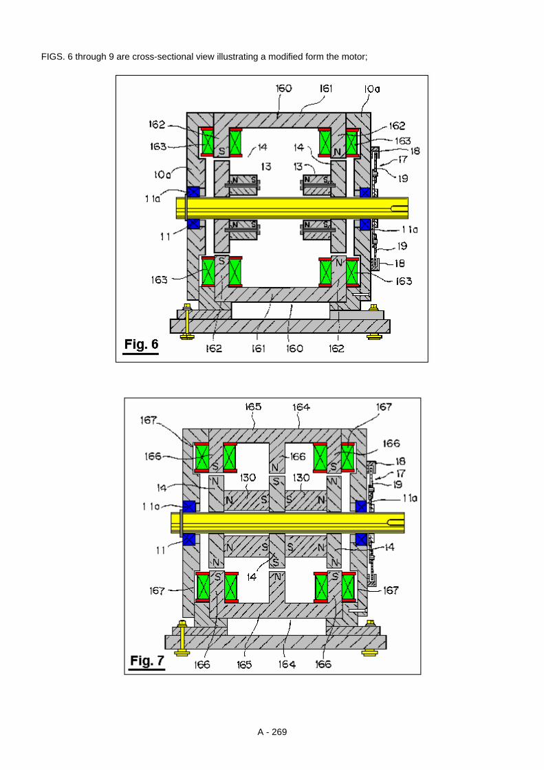
A - 269
FIGS. 6 through 9 are cross-sectional view illustrating a modified form the motor;

A - 270
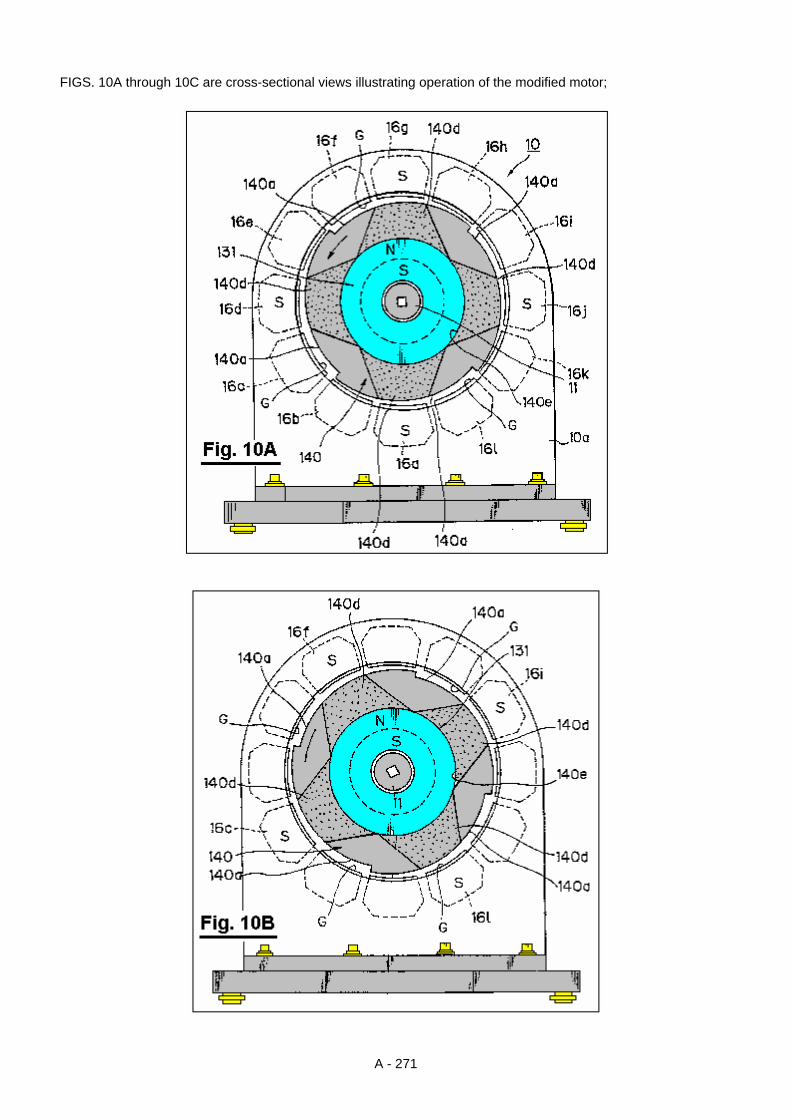
A - 271
FIGS. 10A through 10C are cross-sectional views illustrating operation of the modified motor;
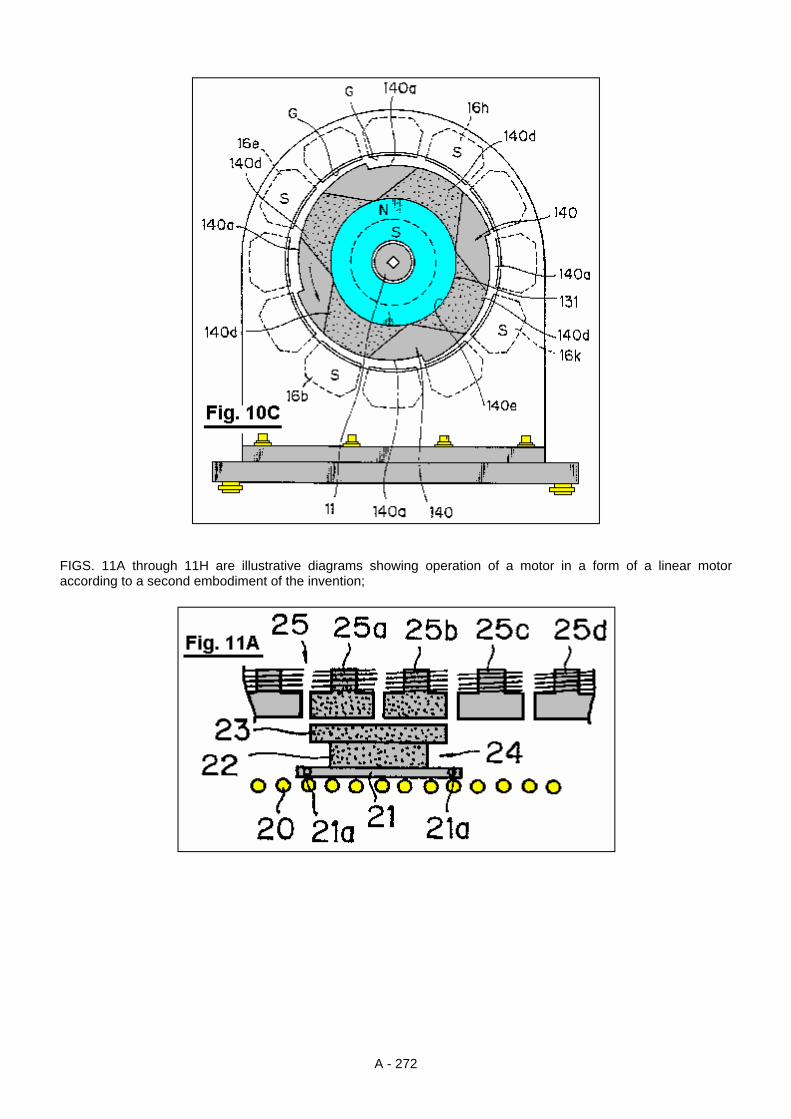
A - 272
FIGS. 11A through 11H are illustrative diagrams showing operation of a motor in a form of a linear motor according to a second embodiment of the invention;

A - 273
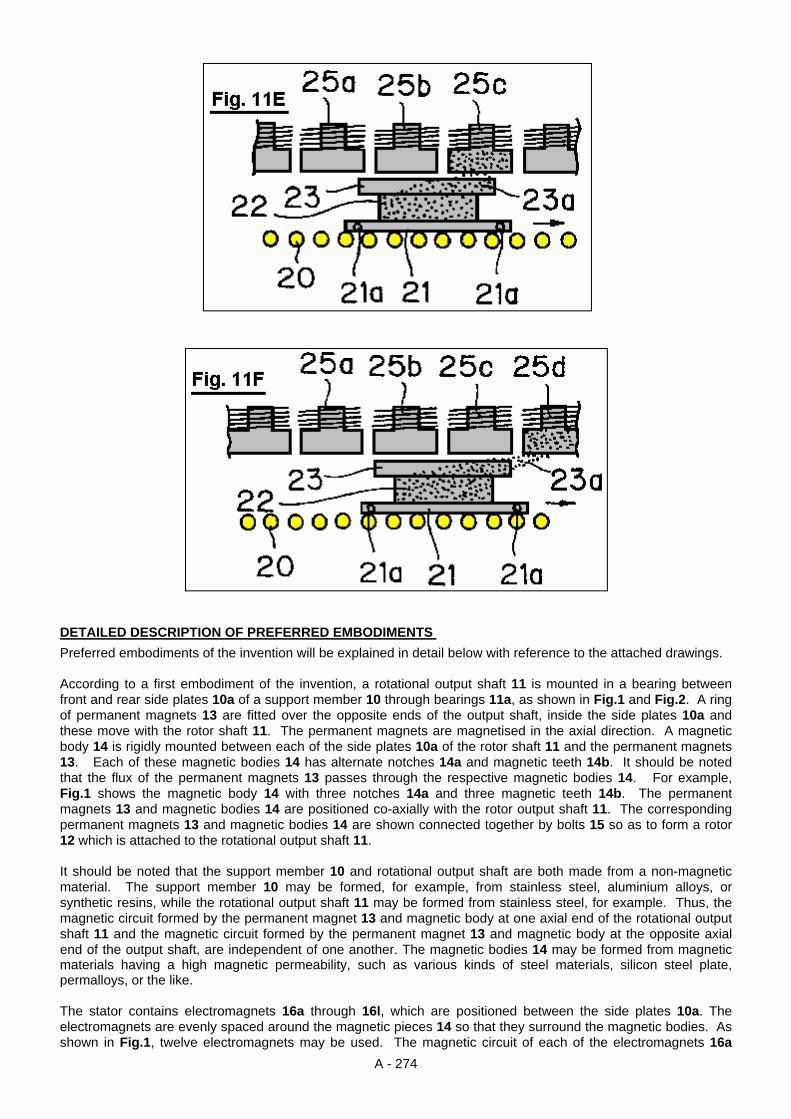
A - 274
DETAILED DESCRIPTION OF PREFERRED EMBODIMENTS Preferred embodiments of the invention will be explained in detail below with reference to the attached drawings. According to a first embodiment of the invention, a rotational output shaft 11 is mounted in a bearing between front and rear side plates 10a of a support member 10 through bearings 11a, as shown in Fig.1 and Fig.2. A ring of permanent magnets 13 are fitted over the opposite ends of the output shaft, inside the side plates 10a and these move with the rotor shaft 11. The permanent magnets are magnetised in the axial direction. A magnetic body 14 is rigidly mounted between each of the side plates 10a of the rotor shaft 11 and the permanent magnets 13. Each of these magnetic bodies 14 has alternate notches 14a and magnetic teeth 14b. It should be noted that the flux of the permanent magnets 13 passes through the respective magnetic bodies 14. For example, Fig.1 shows the magnetic body 14 with three notches 14a and three magnetic teeth 14b. The permanent magnets 13 and magnetic bodies 14 are positioned co-axially with the rotor output shaft 11. The corresponding permanent magnets 13 and magnetic bodies 14 are shown connected together by bolts 15 so as to form a rotor 12 which is attached to the rotational output shaft 11. It should be noted that the support member 10 and rotational output shaft are both made from a non-magnetic material. The support member 10 may be formed, for example, from stainless steel, aluminium alloys, or synthetic resins, while the rotational output shaft 11 may be formed from stainless steel, for example. Thus, the magnetic circuit formed by the permanent magnet 13 and magnetic body at one axial end of the rotational output shaft 11 and the magnetic circuit formed by the permanent magnet 13 and magnetic body at the opposite axial end of the output shaft, are independent of one another. The magnetic bodies 14 may be formed from magnetic materials having a high magnetic permeability, such as various kinds of steel materials, silicon steel plate, permalloys, or the like. The stator contains electromagnets 16a through 16l, which are positioned between the side plates 10a. The electromagnets are evenly spaced around the magnetic pieces 14 so that they surround the magnetic bodies. As shown in Fig.1, twelve electromagnets may be used. The magnetic circuit of each of the electromagnets 16a

A - 275
through 16l is arranged so as to be independent of each other, so that no flux of a magnetised electromagnet passes through the iron cores of the adjacent electromagnets. The iron cores of the electromagnets 16a through 16l are positioned parallel to the rotor axis shaft 11, and positioned with only a slight gap between them and the magnetic bodies 14. Some of the electromagnets 16a through 16l are located at a position corresponding to boundary portions 14c1 through 14c6 between the notch 14a and the magnetic tooth 14b. For example, as shown in Fig.1, electromagnets 16a, 16b, 16e, 16f, 16i and 16j are positioned opposite the boundary portions 14c1, 14c2, 14c3, 14c4, 14c5, and 14c6, respectively. Fig.5A shows a path of magnetic flux created by the permanent magnet 13 when the electromagnets are not excited or magnetised, while, Fig.5B shows a path of magnetic flux created by the permanent magnet 13 and a path of magnetic flux created by the windings of the electromagnets when the electromagnets are magnetised. As will be clear from Fig.5A and Fig.5B, both paths of magnetic flux represent a uni-polar distribution in which N-pole or S-pole evenly appears at the opposite axial ends. When the electromagnets are magnetised, the magnetic fields of the permanent magnet and electromagnets co-operate or interact with each other so as to generate a rotational torque. Excitation change-over mechanism 17 for sequentially exciting or magnetising the electromagnets 16a through 16l is basically consisted of a conventional excitation circuit for supplying direct current to each windings of the electromagnets 16a through 16l. In this embodiment, the change-over portion for changing electric feed to the electromagnets 16a through 16l includes a plurality of optical sensors 18 and a light shield plate 19 for turning the optical sensors ON and OFF as shown in Fig.6. The optical sensors 18 are spaced apart from one another with a space between them for permitting the light shield plate 19 to pass through a light emitting element and a light receiving element. The optical sensors 18 are disposed in the outer surface of one of the side plates 10a equally spaced apart along the circumference, so that they are positioned to correspond to the electromagnets 16a through 16l (for example, the optical sensor 18 is shown to be disposed in the outer surface of the rear side plate). The light shielding plate 19 is fixed to the rotational output shaft 11 at the end thereof, the light shielding plate protruding from the rear side plate 10a on which the optical sensors are mounted. According to the illustrated embodiment, when a particular optical sensor 18 is blocked by the light shielding plate 19, the electromagnet corresponding to such optical sensor 18 is supplied with electricity. The operation of the first embodiment described above will be explained with reference to Fig.4A through Fig.4H. When the electromagnets 16a through 16l are not supplied with electricity by means of the excitation changeover mechanism 17, the electromagnets 16c, 16d, 16g, 16h, 16k and 16l opposed to the magnetic teeth 14b with a small gap between them merely serve as a magnetic material disposed within the magnetic field of the permanent magnet 13 (refer to shaded portion in Fig.4A), so as to absorb the magnetic teeth 14b, and the rotor 12 remains stationary. When the electromagnets 16a, 16e and 16i positioned adjacent to the boundary portion 14c1, 14c3 and 14c5 formed between the respective notches 14a and the magnetic teeth 14b are magnetised or excited simultaneously by means of the excitation change-over mechanism, as shown in Fig.4B, the magnetic field of the permanent magnet 13 and the magnetic fields of the electromagnets 16a, 16e and 16i interact with each other, so that a magnetic flux 14d passing through the magnetic body 14 instantaneously converges to the electromagnets 16a, 16e, and 16i. In this way, the rotor 12 is imparted with a rotational torque in a direction in which the magnetic flux 14d will be widened, i.e., counterclockwise direction as viewed in Fig.4B. Fig.4C through Fig.4G illustrate change in the width of the magnetic flux 14d in accordance with rotation of the rotor 12. When the width of the magnetic flux becomes maximised, i.e., when only the magnetic teeth 14b are opposed to the electromagnets 16a, 16e and 16i, while the notches 14a are displaced completely away from the electromagnets 16a, 16e and 16i, the width of the magnetic flux 14d is maximised. Thus, an absorption force acting between the permanent magnet 13 and the electromagnets 16a, 16e and 16i is maximised. On the other hand, the rotational torque acting on the rotor 12 becomes zero. Before the rotational torque acting on the rotor 12 becomes zero, i.e., as the boundary portion 14c1, 14c3 and 14c5 approach another electromagnets 16b, 16f and 16j positioned ahead of (with regard to the rotational direction), respectively, the electromagnets 16a, 16e and 16i are demagnetised and the electromagnets 16b, 16f and 16j are excited or magnetised by means of the excitation change-over mechanism 17. Thus, the magnetic
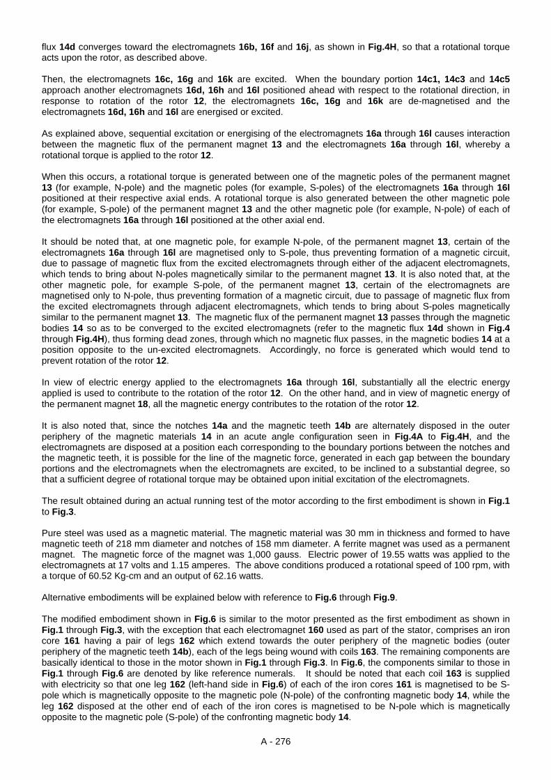
A - 276
flux 14d converges toward the electromagnets 16b, 16f and 16j, as shown in Fig.4H, so that a rotational torque acts upon the rotor, as described above. Then, the electromagnets 16c, 16g and 16k are excited. When the boundary portion 14c1, 14c3 and 14c5 approach another electromagnets 16d, 16h and 16l positioned ahead with respect to the rotational direction, in response to rotation of the rotor 12, the electromagnets 16c, 16g and 16k are de-magnetised and the electromagnets 16d, 16h and 16l are energised or excited. As explained above, sequential excitation or energising of the electromagnets 16a through 16l causes interaction between the magnetic flux of the permanent magnet 13 and the electromagnets 16a through 16l, whereby a rotational torque is applied to the rotor 12. When this occurs, a rotational torque is generated between one of the magnetic poles of the permanent magnet 13 (for example, N-pole) and the magnetic poles (for example, S-poles) of the electromagnets 16a through 16l positioned at their respective axial ends. A rotational torque is also generated between the other magnetic pole (for example, S-pole) of the permanent magnet 13 and the other magnetic pole (for example, N-pole) of each of the electromagnets 16a through 16l positioned at the other axial end. It should be noted that, at one magnetic pole, for example N-pole, of the permanent magnet 13, certain of the electromagnets 16a through 16l are magnetised only to S-pole, thus preventing formation of a magnetic circuit, due to passage of magnetic flux from the excited electromagnets through either of the adjacent electromagnets, which tends to bring about N-poles magnetically similar to the permanent magnet 13. It is also noted that, at the other magnetic pole, for example S-pole, of the permanent magnet 13, certain of the electromagnets are magnetised only to N-pole, thus preventing formation of a magnetic circuit, due to passage of magnetic flux from the excited electromagnets through adjacent electromagnets, which tends to bring about S-poles magnetically similar to the permanent magnet 13. The magnetic flux of the permanent magnet 13 passes through the magnetic bodies 14 so as to be converged to the excited electromagnets (refer to the magnetic flux 14d shown in Fig.4 through Fig.4H), thus forming dead zones, through which no magnetic flux passes, in the magnetic bodies 14 at a position opposite to the un-excited electromagnets. Accordingly, no force is generated which would tend to prevent rotation of the rotor 12. In view of electric energy applied to the electromagnets 16a through 16l, substantially all the electric energy applied is used to contribute to the rotation of the rotor 12. On the other hand, and in view of magnetic energy of the permanent magnet 18, all the magnetic energy contributes to the rotation of the rotor 12. It is also noted that, since the notches 14a and the magnetic teeth 14b are alternately disposed in the outer periphery of the magnetic materials 14 in an acute angle configuration seen in Fig.4A to Fig.4H, and the electromagnets are disposed at a position each corresponding to the boundary portions between the notches and the magnetic teeth, it is possible for the line of the magnetic force, generated in each gap between the boundary portions and the electromagnets when the electromagnets are excited, to be inclined to a substantial degree, so that a sufficient degree of rotational torque may be obtained upon initial excitation of the electromagnets. The result obtained during an actual running test of the motor according to the first embodiment is shown in Fig.1 to Fig.3. Pure steel was used as a magnetic material. The magnetic material was 30 mm in thickness and formed to have magnetic teeth of 218 mm diameter and notches of 158 mm diameter. A ferrite magnet was used as a permanent magnet. The magnetic force of the magnet was 1,000 gauss. Electric power of 19.55 watts was applied to the electromagnets at 17 volts and 1.15 amperes. The above conditions produced a rotational speed of 100 rpm, with a torque of 60.52 Kg-cm and an output of 62.16 watts. Alternative embodiments will be explained below with reference to Fig.6 through Fig.9. The modified embodiment shown in Fig.6 is similar to the motor presented as the first embodiment as shown in Fig.1 through Fig.3, with the exception that each electromagnet 160 used as part of the stator, comprises an iron core 161 having a pair of legs 162 which extend towards the outer periphery of the magnetic bodies (outer periphery of the magnetic teeth 14b), each of the legs being wound with coils 163. The remaining components are basically identical to those in the motor shown in Fig.1 through Fig.3. In Fig.6, the components similar to those in Fig.1 through Fig.6 are denoted by like reference numerals. It should be noted that each coil 163 is supplied with electricity so that one leg 162 (left-hand side in Fig.6) of each of the iron cores 161 is magnetised to be S-pole which is magnetically opposite to the magnetic pole (N-pole) of the confronting magnetic body 14, while the leg 162 disposed at the other end of each of the iron cores is magnetised to be N-pole which is magnetically opposite to the magnetic pole (S-pole) of the confronting magnetic body 14.

A - 277
According to this modified embodiment, it is possible to significantly reduce leakage of the magnetic flux created by the electromagnets 160 in gaps each defined between the surfaces of the magnetic poles of the electromagnets 160 and the outer peripheries of the magnetic teeth 14b of the magnetic bodies 14. An alternative embodiment shown in Fig.7 is similar to the motor shown in Fig.1 through Fig.8, with the exception that: an additional magnetic body 14 is mounted on the rotational output shaft 11 at it’s axial midpoint; two permanent magnets 130 are freely mounted on the output shaft 11 in the manner shown in Fig.6; and each iron core 165 is provided with three legs 166 positioned at the opposite axial ends and midpoint thereof and extending toward the respective outer periphery of the magnetic bodies, with the legs 166 positioned at axial opposite ends of the respective iron cores 165 being wound with a coil 167, which form electromagnets 164. The remaining components are substantially the same as those in the motor shown in Fig.1 through Fig.3. It should be noted here, that the rotational output shaft 11 may be formed from either magnetic materials or non-magnetic materials. As shown in Fig.7, each of the coils 167 is supplied with electricity so that the legs 166 positioned at the opposite axial ends of each of the iron cores 164 is magnetised to be S-pole which is magnetically opposite to the magnetic pole (N-pole) of the confronting magnetic body 14. By this, the leg 166 positioned at the midpoint of the iron core 165 is magnetised to be N-pole which is magnetically opposite to the magnetic pole (S-pole) of the confronting magnetic body 14. In this embodiment, it is also possible, as in the modified embodiment shown in Fig.6, to significantly reduce the leakage of the magnetic flux generated by the electromagnets 164. In addition to this, it is also possible to obtain a rotational torque between the leg 166 positioned at the midpoint of the iron core and the magnetic body 14 positioned at the axial midpoint of the rotational output shaft 11. Accordingly, a higher rotational torque may be obtained with the same amount of electrical consumption, in comparison with the embodiment shown in Fig.6. A further embodiment shown in Fig.8 is similar to the motor shown in Fig.1 though Fig.3, with the exception that a permanent magnet magnetised in the radial direction, rather than in the axial direction is employed. The permanent magnet 131 of an annular configuration has, for example, N-pole in the outer periphery and S-pole in the inner periphery. The permanent magnet 131 is received within a cavity 14e provided in the respective magnetic body 14 at the intermediate portion thereof as disposed at the opposite axial ends of the rotational output shaft 11. The remaining components are identical to those in the motor shown in Fig.1 though Fig.3. The components identical to those in the motor shown in Fig.1 though Fig.3 are denoted by the same reference numerals. It should be noted that this embodiment may also employ the electromagnets 160 shown in Fig.6. In this embodiment, the rotational output shaft 11 may be formed from magnetic materials, rather than non-magnetic materials. Further embodiment shown in Fig.9 is similar to the motor shown in Fig.1 though Fig.3, with three exceptions. The first exception is that a permanent magnet magnetised in the radial direction, rather than in the axial direction is employed. The permanent magnet 131 having an annular configuration has, for example, N-pole in the outer periphery and S-pole in the inner periphery. The permanent magnet 131 is received within a cavity 14e provided in the respective magnetic body 14 at the intermediate portion thereof as disposed at the axial opposite ends of the rotational output shaft 11. The second exception is that an additional magnetic body 14 is disposed at the axial midpoint of the rotational output shaft 11. Finally, the third exception is that the iron core 165 is provided with three legs 166 disposed at the axial opposite ends and the midpoint thereof, respectively, and extending toward the outer periphery of the magnetic body 14, with the legs positioned at the opposite axial ends being wound with respective coils so as to form an electromagnet 164. The remaining components are identical to those in the motor shown in Fig.1 though Fig.3. The components identical to those in the motor shown in Fig.1 though Fig.3 are denoted by the same reference numerals. As shown in Fig.9, each coil is supplied with electricity so that the legs 166 disposed at opposite axial ends of the iron core 165 are magnetised to be S-pole which is magnetically opposite to the magnetic pole (N-pole) of the confronting magnetic body 14. By this, the leg 166 disposed at the midpoint of the iron core 165 is magnetised to be N-pole which is magnetically opposite to the magnetic pole (S-pole) of the confronting magnetic body 14. According to the embodiment described above, the rotational output shaft 11 may be formed from magnetic materials rather than non-magnetic materials. With this embodiment, it is possible to obtain the same effect as that obtained with the embodiment shown in Fig.7. Further the alternative embodiments shown in Fig.10A to Fig.10C are similar to the motor shown in Fig.1 though Fig.3, with the exception that: like the embodiments shown in Fig.8 and Fig.9, an annular permanent magnet 131 is employed which is received in a cavity 140e provided in the central portion 140 of the magnetic body 140; the magnetic body 140 is provided with notches 140a in the outer peripheral portion thereof, so that the gap G
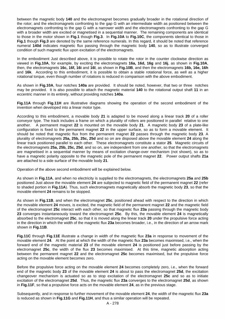
A - 278
between the magnetic body 140 and the electromagnet becomes gradually broader in the rotational direction of the rotor; and the electromagnets confronting to the gap G with an intermediate width as positioned between the electromagnets confronting to the gap G with a narrower width and the electromagnets confronting to the gap G with a broader width are excited or magnetised in a sequential manner. The remaining components are identical to those in the motor shown in Fig.1 though Fig.3. In Fig.10A to Fig.10C, the components identical to those in Fig.1 though Fig.3 are denoted by the same reference numerals. In this regard, it should be noted that reference numeral 140d indicates magnetic flux passing through the magnetic body 140, so as to illustrate converged condition of such magnetic flux upon excitation of the electromagnets. In the embodiment Just described above, it is possible to rotate the rotor in the counter clockwise direction as viewed in Fig.10A, for example, by exciting the electromagnets 16a, 16d, 16g and 16j, as shown in Fig.10A, then, the electromagnets 16c, 16f, 16i and 16l, as shown in Fig.10B, and then the electromagnets 16b, 16e, 16h and 16k. According to this embodiment, it is possible to obtain a stable rotational force, as well as a higher rotational torque, even though number of rotations is reduced in comparison with the above embodiment. As shown in Fig.10A, four notches 140a are provided. It should be noted, however, that two or three notches may be provided. It is also possible to attach the magnetic material 140 to the rotational output shaft 11 in an eccentric manner in its entirety, without providing notches 140a. Fig.11A through Fig.11H are illustrative diagrams showing the operation of the second embodiment of the invention when developed into a linear motor type. According to this embodiment, a movable body 21 is adapted to be moved along a linear track 20 of a roller conveyor type. The track includes a frame on which a plurality of rollers are positioned in parallel relative to one another. A permanent magnet 22 is mounted on the movable body 21. A magnetic body 23 of a plate-like configuration is fixed to the permanent magnet 22 in the upper surface, so as to form a movable element. It should be noted that magnetic flux from the permanent magnet 22 passes through the magnetic body 23. A plurality of electromagnets 25a, 25b, 25c, 25d and so on are disposed above the movable element 24 along the linear track positioned parallel to each other. These electromagnets constitute a stator 25. Magnetic circuits of the electromagnets 25a, 25b, 25c, 25d, and so on, are independent from one another, so that the electromagnets are magnetised in a sequential manner by means of excitation change-over mechanism (not shown), so as to have a magnetic polarity opposite to the magnetic pole of the permanent magnet 22. Power output shafts 21a are attached to a side surface of the movable body 21. Operation of the above second embodiment will be explained below. As shown in Fig.11A, and when no electricity is supplied to the electromagnets, the electromagnets 25a and 25b positioned Just above the movable element 24 are subjected to magnetic field of the permanent magnet 22 (refer to shaded portion in Fig.11A). Thus, such electromagnets magnetically absorb the magnetic body 23, so that the movable element 24 remains to be stopped. As shown in Fig.11B, and when the electromagnet 25c, positioned ahead with respect to the direction in which the movable element 24 moves, is excited, the magnetic field of the permanent magnet 22 and the magnetic field of the electromagnet 25c interact with each other, so that magnetic flux 23a passing through the magnetic body 23 converges instantaneously toward the electromagnet 25c. By this, the movable element 24 is magnetically absorbed to the electromagnet 25c, so that it is moved along the linear track 20 under the propulsive force acting in the direction in which the width of the magnetic flux 23a becomes broader, i.e., in the direction of an arrow mark shown in Fig.11B. Fig.11C through Fig.11E illustrate a change in width of the magnetic flux 23a in response to movement of the movable element 24. At the point at which the width of the magnetic flux 23a becomes maximised, i.e., when the forward end of the magnetic material 23 of the movable element 24 is positioned just before passing by the electromagnet 25c, the width of the flux 23 becomes maximised. At this time, magnetic absorption acting between the permanent magnet 22 and the electromagnet 25c becomes maximised, but the propulsive force acting on the movable element becomes zero. Before the propulsive force acting on the movable element 24 becomes completely zero, i.e., when the forward end of the magnetic body 23 of the movable element 24 is about to pass the electromagnet 25d, the excitation changeover mechanism is actuated so as to stop excitation of the electromagnet 25c and so as to initiate excitation of the electromagnet 25d. Thus, the magnetic flux 23a converges to the electromagnet 25d, as shown in Fig.11F, so that a propulsive force acts on the movable element 24, as in the previous stage. Subsequently, and in response to further movement of the movable element 24, the width of the magnetic flux 23a is reduced as shown in Fig.11G and Fig.11H, and thus a similar operation will be repeated.
A - 279
The sequential excitation of the electromagnets, as explained above, causes interaction between the magnetic fields of permanent magnet 22 and electromagnets, whereby a propulsive force is applied to the movable element 24. It should be noted that, when the magnetic polarity of the permanent magnet 22 confronting the electromagnets is assumed to be N-pole, the electromagnet 25c is magnetised solely to be S-pole, so as to prevent formation of a magnetic circuit by virtue of passage of magnetic flux from the electromagnet 25c through to the adjacent electromagnets 25b and 25d, which formation, if it occurs, tends to cause the polarity of the electromagnets to be N-pole identical to the magnetic pole of the permanent magnet 22. Accordingly, and in a manner similar to that in the first embodiment, no force is generated which tends to interfere with movement of the movable element 24. In the present invention, a plurality of electromagnets serving as a stator are so arranged that their respective magnetic circuits become independent from one another. The electromagnets are also arranged so that they are solely magnetised or excited to have a magnetic polarity opposite to the magnetic pole of the confronting permanent magnet. Thus, each electromagnet is prevented from becoming magnetised to the same polarity as that of the permanent magnet, which may occur when magnetic flux from a particular electromagnet passes through to adjacent electromagnets. Accordingly, no force will be exerted which tends to interfere with the intended movement of a rotor or a movable element. As a result, electric energy applied to the electromagnets may be efficiently utilised, while, at the same time, magnetic energy contained in the permanent magnet may-also be efficiently utilised. The coils constituting the electromagnets are consistently supplied with electric current with the same polarity, without any change, so that heating of coils may be prevented. Further, it is possible to obviate the problems of vibration and noise which might occur due to a repulsive force being generated when polarity of an electric current supplied to the coils is changed.
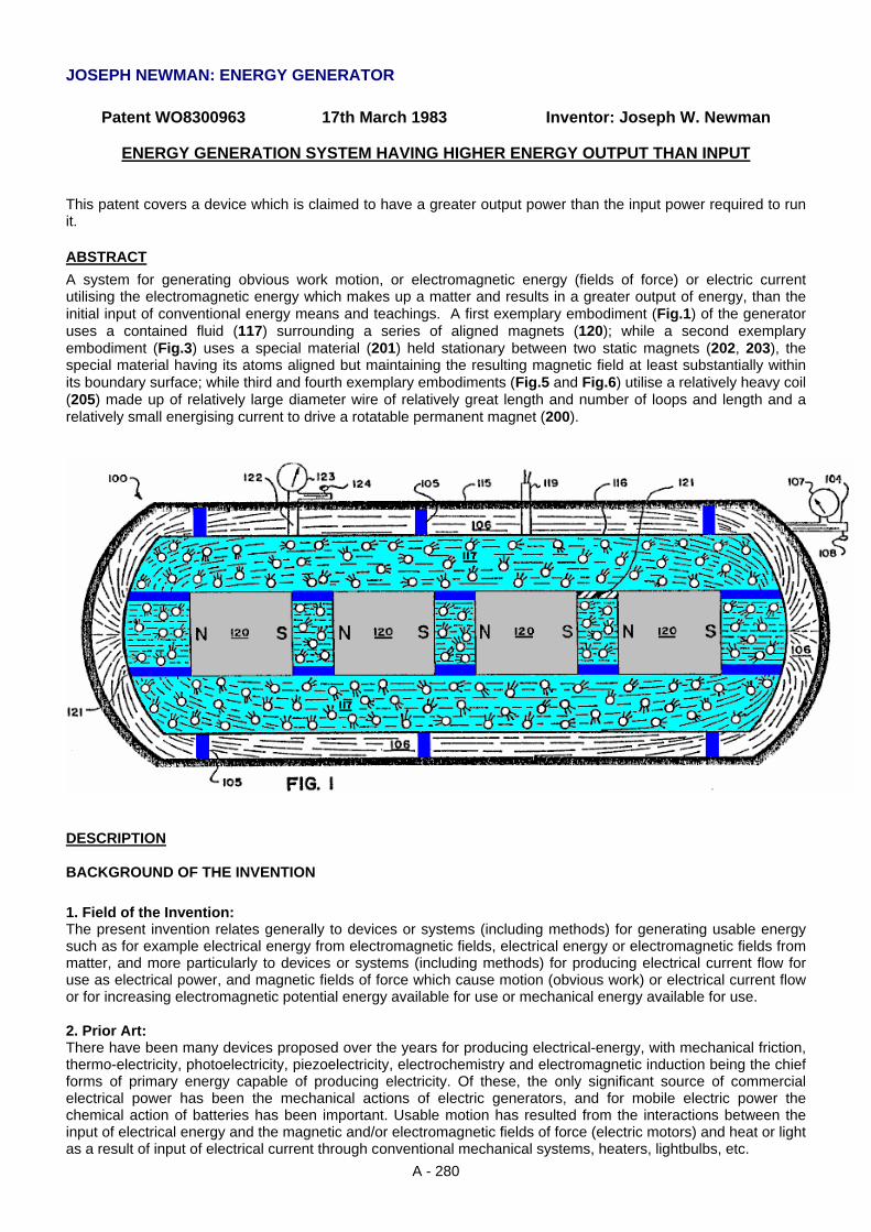
A - 280
JOSEPH NEWMAN: ENERGY GENERATOR
Patent WO8300963 17th March 1983 Inventor: Joseph W. Newman
ENERGY GENERATION SYSTEM HAVING HIGHER ENERGY OUTPUT THAN INPUT This patent covers a device which is claimed to have a greater output power than the input power required to run it. ABSTRACT A system for generating obvious work motion, or electromagnetic energy (fields of force) or electric current utilising the electromagnetic energy which makes up a matter and results in a greater output of energy, than the initial input of conventional energy means and teachings. A first exemplary embodiment (Fig.1) of the generator uses a contained fluid (117) surrounding a series of aligned magnets (120); while a second exemplary embodiment (Fig.3) uses a special material (201) held stationary between two static magnets (202, 203), the special material having its atoms aligned but maintaining the resulting magnetic field at least substantially within its boundary surface; while third and fourth exemplary embodiments (Fig.5 and Fig.6) utilise a relatively heavy coil (205) made up of relatively large diameter wire of relatively great length and number of loops and length and a relatively small energising current to drive a rotatable permanent magnet (200).
DESCRIPTION BACKGROUND OF THE INVENTION 1. Field of the Invention: The present invention relates generally to devices or systems (including methods) for generating usable energy such as for example electrical energy from electromagnetic fields, electrical energy or electromagnetic fields from matter, and more particularly to devices or systems (including methods) for producing electrical current flow for use as electrical power, and magnetic fields of force which cause motion (obvious work) or electrical current flow or for increasing electromagnetic potential energy available for use or mechanical energy available for use. 2. Prior Art: There have been many devices proposed over the years for producing electrical-energy, with mechanical friction, thermo-electricity, photoelectricity, piezoelectricity, electrochemistry and electromagnetic induction being the chief forms of primary energy capable of producing electricity. Of these, the only significant source of commercial electrical power has been the mechanical actions of electric generators, and for mobile electric power the chemical action of batteries has been important. Usable motion has resulted from the interactions between the input of electrical energy and the magnetic and/or electromagnetic fields of force (electric motors) and heat or light as a result of input of electrical current through conventional mechanical systems, heaters, lightbulbs, etc.
A - 281
All of the prior art systems are designed accordingly to rigid mathematical laws taught both in physics and electrical engineering which coincide with the hypothesis rigidly accepted by the industrial and scientific communities concerning the Second Law of Thermodynamics (1850). From the foregoing generally accepted hypothesis it has also been generally accepted and rigidly taught in physics and electrical engineering that the electric current flowing in a closed circuit from a battery, electric generator, etc. is used up in the mechanical device being operated by this flow of electric current, and that all such electric current producing systems would only put out at most work equal to the work initially put into the system, or in accordance with generally accepted laws stating that a particular electrical generating system was only capable of a given output of energy and no more. These beliefs have till this date still remained rigid in both the industrial and scientific communities in spite of proof of Einstein's equation E=mC2 Nuclear reactors convert matter into usable electromagnetic energy in the form of heat, which converts water into steam to turn conventional turbines for production of electric current by conventional electrical generating means. This system is extremely inefficient using less than 1% of the energy of the atom and producing a deluge of contaminated materials which has caused a serious problem as to safe disposal. Additionally, the basic electrical generators is use throughout the world today utilise the principle of causing relative movement between an electrical conductor (for example a rotor) and a magnetic field produced by a magnet or an electromagnet (for example a stator), all using the generally accepted hypothesis that the greater the relative speed or movement between the two are concerned and the more normal or perpendicular the relative movement of the conductive material to the lines of force of the electromagnetic field, the greater will be the efficiency of the prior art electrical generator. Additionally, all of the prior art systems are based on the generally accepted hypothesis that the greater the electrical conductivity of the material being moved through the field, the more efficient will be the electrical generation. From the foregoing generally accepted hypotheses, it also has been generally accepted that there should always be movement between, for example, the rotor and stator elements, and that only generally accepted electrical conductors, that is materials with high electrical conductivity, will effectively serve in an electrical generation system. However, in one of the systems (Fig.3) of the present invention, electrical generation can occur with relatively static elements and with materials that are not generally considered to be of high electrical conductivity, although, of course, the present invention likewise can utilise relatively moving elements as well as materials of generally accepted high electrical conductivity, if so desired, as occurs in the systems of the present invention illustrated in Fig.5 and Fig.6. The prior art has failed to understand certain physical aspects of matter and the makeup of electromagnetic fields, which failure is corrected by the present invention. BRIEF DESCRIPTION OF DRAWINGS For a further understanding of the nature and objects of the present invention, reference should be had to the following detailed description, taken in conjunction with the accompanying drawings, in which like parts are given like reference numerals and wherein:

A - 282
Fig.1 is a schematic, side view in generalised, representational form of a first embodiment of an electrical generator based on the principles and guidelines of the present invention.
Fig.2 is a close-up view in general form of an electrical charge pick-up element which can be used in the generator illustrated in Fig.1.
Fig.3 is a schematic view in generalised, representational form of a second embodiment of an electrical generator based on the principles and guidelines of the present invention.
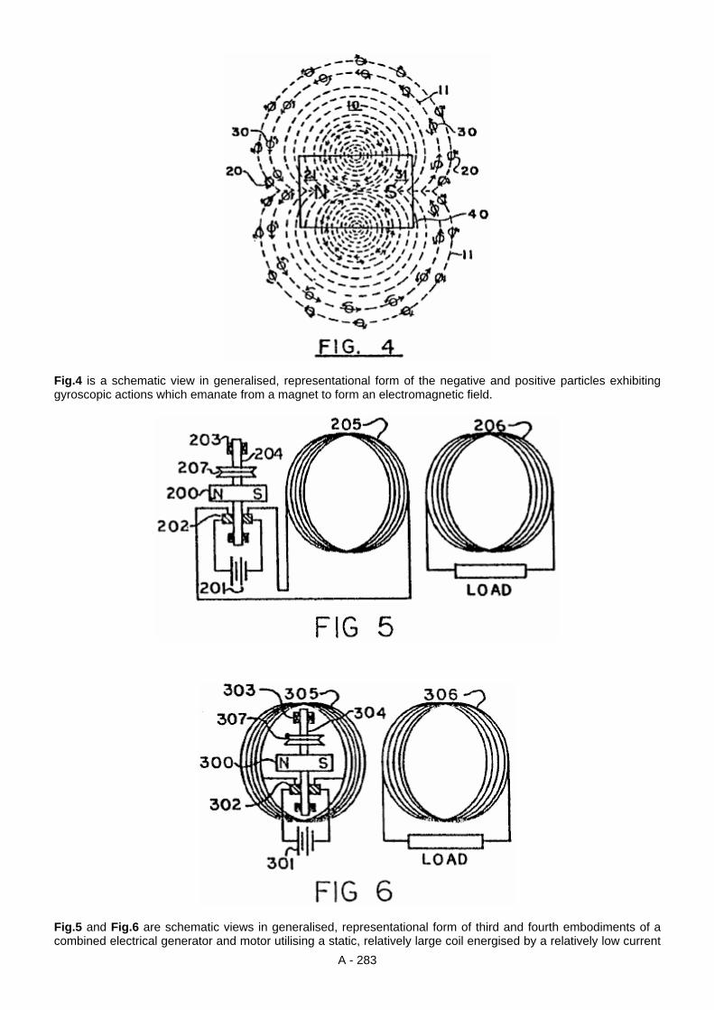
A - 283
Fig.4 is a schematic view in generalised, representational form of the negative and positive particles exhibiting gyroscopic actions which emanate from a magnet to form an electromagnetic field.
Fig.5 and Fig.6 are schematic views in generalised, representational form of third and fourth embodiments of a combined electrical generator and motor utilising a static, relatively large coil energised by a relatively low current

A - 284
driving a rotatable magnet, wherein in the embodiment of Fig.5 the rotatable magnet is positioned along side of the coil and in the embodiment of Fig.6 the rotatable magnet is positioned within the open core of the coil. DETAILED DESCRIPTION OF-PREFERRED EMBODIMENTS: Basic Principles and Guidelines In accordance with the principles of the present invention and as generally illustrated in Fig.3, an electromagnetic field 10 comprises flows of quanta or particles 20, 30 of electrical energy flowing from each of the poles 21, 31 of a magnet (or electromagnet) 40 to the other pole, following the "lines of force" 11 of the electromagnetic field. These particles 20, 30, believed to be travelling at the speed of light, are always coming out of one end 21, 31, respectively, of the magnet 40 and going into the other pole 31, 21, respectively, flowing from a relatively high energy source to a low energy source. These particles 20, 30 are, it is believed, negative and positive charges and have a spin producing a gyroscopic motion and follow the mechanical laws of gyroscopic action. The mass of each of the particles 20, 30 equals the energy of the particle divided by the speed of light squared. The peripheral speed of the gyroscopic spin of the particles is believed to be the speed of light. For purposes of illustration only and as a matter of nomenclature, the positive charge particle 20 is going in one direction ('-'N" to "S") with a clockwise spin, and the negative charge particle 30 is going in the opposite direction with a counter-clockwise spin. Of course, if a particle such as 20 or 30 is flipped around one-hundred-and-eighty degrees, it becomes the opposite charge or type of particle. The electromagnetic field 10 is thus the orderly flow of the positive and negative charges 20, 30 moving at the speed of light from the north and south poles 21, 31, to the south and north poles 31, 21, respectively, and follow the paths of what is termed in the art as the "lines of force" 11 of the electromagnetic field 10. As is known from the laws of gyroscopes, a gyroscopic particle or body moves at right angles to the direction of an applied force. Therefore, when a force is applied to the electrical energy particles 20, 30, they will move at right angles to that force. It should also be noted from known gyroscopic laws that the electrical energy particles 20, 30, when they move with their gyroscopic axis straight into an object, tend to knock that object straight, but, if that object hits the particles at an angle to the axis other than at zero or one-hundred-and-eighty degrees, the particles are moved off at an angle from the straight. Additionally, it is noted that a magnetic field caused by a current flowing through a wire comes from negative and positive particles, such as 20, 30, with a net flow of such particles going in the same direction but with opposite spin. In the system and method of the present invention, the foregoing principles serve as guidelines in the present invention. Reference is further had to pages DD23 through DD27 of the Disclosure Document and to page 8, line 26 through page 11, line 23 of the prior application Serial number 25,907 and its Figures 7 - 10. From the foregoing disclosures, many different devices, structures, and methods are possible to embody the principles and guidelines of the system of the present invention, which will in general utilise a material or substance or structure to place a force at the proper angle to the gyroscopic particles 20, 30 wherein the particles 20, 30 follow a path or paths which do not cancel one another out, thereby producing electrical current at appropriate outputs for further use or for increasing available potential electrical energy for ultimate use.
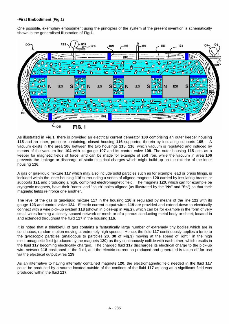
A - 285
-First Embodiment (Fig.1) One possible, exemplary embodiment using the principles of the system of the present invention is schematically shown in the generalised illustration of Fig.1.
As illustrated in Fig.1, there is provided an electrical current generator 100 comprising an outer keeper housing 115 and an inner, pressure containing, closed housing 116 supported therein by insulating supports 105. A vacuum exists in the area 106 between the two housings 115, 116, which vacuum is regulated and induced by means of the vacuum line 104 with its gauge 107 and its control valve 108. The outer housing 115 acts as a keeper for magnetic fields of force, and can be made for example of soft iron, while the vacuum in area 106 prevents the leakage or discharge of static electrical charges which might build up on the exterior of the inner housing 116. A gas or gas-liquid mixture 117 which may also include solid particles such as for example lead or brass filings, is included within the inner housing 116 surrounding a series of aligned magnets 120 carried by insulating braces or supports 121 and producing a high, combined electromagnetic field. The magnets 120, which can for example be cryogenic magnets, have their "north" and "south" poles aligned (as illustrated by the "Ns" and "Ss") so that their magnetic fields reinforce one another. The level of the gas or gas-liquid mixture 117 in the housing 116 is regulated by means of the line 122 with its gauge 123 and control valve 124. Electric current output wires 119 are provided and extend down to electrically connect with a wire pick-up system 118 (shown in close-up in Fig.2), which can be for example in the form of very small wires forming a closely spaced network or mesh or of a porous conducting metal body or sheet, located in and extended throughout the fluid 117 in the housing 116. It is noted that a thimbleful of gas contains a fantastically large number of extremely tiny bodies which are in continuous, random motion moving at extremely high speeds. Hence, the fluid 117 continuously applies a force to the gyroscopic particles (analogous to particles 20, 30 of Fig.3) moving at the speed of light ' in the high electromagnetic field (produced by the magnets 120) as they continuously collide with each other, which results in the fluid 117 becoming electrically charged. The charged fluid 117 discharges its electrical charge to the pick-up wire network 118 positioned in the fluid, and the electric current so produced and generated is taken off for use via the electrical output wires 119. As an alternative to having internally contained magnets 120, the electromagnetic field needed in the fluid 117 could be produced by a source located outside of the confines of the fluid 117 as long as a significant field was produced within the fluid 117.

A - 286
-Second Embodiment (Fig.3) A further exemplary, generalised embodiment utilising the principles of the system of the present invention is shown in schematic form in Fig.3. The electrical current generator 200 of Fig.3 comprises an extended member 201 of a special material having its atoms especially aligned to produce electric current when positioned in an electromagnetic field but which does not on its own exhibit any substantial magnetic field outside of its boundary surfaces but substantially contains the field within itself. This is in contrast to "magnetic" materials which likewise have atom alignment but which also exhibit or produce a substantial magnetic field in the area surrounding it. The generator 200 further comprises for example two magnets 202, 203, with their north and south poles facing each other, with the member 201 positioned between them, and with the three elements 201-203 held static with respect to each other. Because of the special nature of the material of the member 201 and its special atom alignment, it will produce a direct current through output line 204 as a result of the gyroscopic actions of the particles of the electromagnetic field 205 produced by the facing magnets 202, 203, on the especially aligned atoms in member 201, which phenomenon occurs even when and even though the member 201 is completely static with respect to the magnets 212, 203. However, it may be desirable in some applications to allow or produce some relative movement between the generator elements 201-203. The output line 204 extends to an appropriate "load" 206 for using the electrical current generated by the generator 200. A return line 207 completes the circuit back to the member 201. Based on experiments to date, it is believed that brass and lead are materials which can have their atoms especially aligned to interact with the gyroscopic particles (analogous to particles 20, 30) flowing between the magnets 202, 203 and will substantially contain within their surface boundaries the magnetic field produced by the aligned atoms or molecules. With respect to producing the proper material with atom alignment for the member 201, it is noted that most materials seem to align their atoms in random directions when formed by conventional methods of production. However, it can be observed that certain materials can be made magnetic by putting the material in an electromagnetic field while cooling from a temperature of around a thousand degrees Centigrade. The magnetism is the result of atom alignment of the material in a given direction (see pages DD19 through DD21 of the Disclosure Document). All materials are affected so as to align parallel or across lines of force when in a powerful electromagnetic-field. Accordingly, if a material while being formed is cooled in an extremely powerful electromagnetic field, the atoms of the material will take a particular alignment. The atom alignment direction could be varied depending on whether the electromagnetic field was aligned with the material or at a ninety degree angle to the material. This would result in the atoms of a material having their particular electromagnetic spin direction primarily along the same axis. However, merely having atom alignment is not sufficient. Additionally the material for the invention should be such that it exhibits very little if any magnetic field in the area surrounding it. Thus it should be noted that the exterior electromagnetic field that occurs from the atom alignment of the conventional magnet is not duplicated in the material of the invention, because the electromagnetic energy resulting from atom alignment in the material of the invention will be primarily contained within the boundaries of the material It is believed that lead, made superconductive by immersion in a bath of for example liquid helium, is such a special material and could for example serve as the material for member 201. This then results in having a material which would place a force at the proper angle on the gyroscopic type particles moving in the electromagnetic field so as to cause an EMF to be produced even when the material was sitting still. (See also first paragraph of page DD23 and paragraphs four, A through E, of page DDl9 of the Disclosure Document). It is believed that high, contained pressures, as well as other methods, can also probably produce atom alignment as the atoms of a conductor or any material will react to sufficient external force. (See first paragraph of page DD35 of the Disclosure Document). This possibility is also indicated by the fact that hard knocks or impacts will demagnetise a magnet. The proper procedure of material production in achieving atom alignment with internally contained fields of force will cause the controlled release of electrical energy in electromagnetic fields of force when the material of the invention is placed in the lines of force of the electromagnetic field. -Third and Fourth Embodiments (Fig.5 and Fig.6)
A - 287
A. Related Principles 1. Numerous scientific tests and experiments made by the inventor indicate that the magnetic field resulting from an electrical current flowing through a conductor is the result of atom alignment within that conductor at an extremely high speed with an ability to reverse atom alignment just as rapidly without the magnetic hysteresis associated with conventional materials considered "magnetic." Prior to this time it has been believed and taught by the scientific community that the magnetic field associated with an electric current carrying conductor was the result of the electric current itself and not of the conductor material, for example copper, which was considered to be "nonmagnetic." Even the inventor was influenced and mislead by these teachings and attempted to mechanically explain and justify the prior teachings, as is seen on page DD-27 of the Disclosure Document which is an important part of this patent application. However, as taught in the present invention, what mechanically happens is that the gyroscopic particles making up the electric current moving in a conductor interact with the electromagnetic makeup of the atoms of the conductor, causing them to align extremely rapidly, thereby then releasing some of their electromagnetic make-up in the form of a magnetic field exactly as explained in great detail for conventional magnetic materials in the Disclosure Document. This is easily proven and understood by taking for example, a size 14-gauge conductor one foot long, winding it into a coil and connecting the coil to a meter and a 1.5 volt battery. The total current registered on the meter will be 1.5 amps and the strength of the magnetic field created from the short conductor will be extremely small. Next, the same type of test is run again but with the length of the conductor increased to for example two thousand feet, but still in a coil. The total current registered on the meter will now be considerably less, but the strength of the magnetic field given off from the conductor will now be extremely large! This shows that the magnetic field is not from the electric current flow, but is the result of the interactions of the gyroscopic particles which make up the electric current interacting with the atoms of the conductor! This causes the gyroscopic particles of the electric current not to be able to make the circuit back to the battery so quickly, and therefore the meter shows less current used. The magnetic field is the result of the atom alignment of the conductor. The more atoms in a conductor (up to a point), the stronger the magnetic field produced from a given amount of electric current input. Again, this is proven by changing the diameter of the conducting wires, and, with the lengths being the same, the strongest magnetic field will result from the conductor with the largest diameter. The reason for this is that there are more conducting atoms to interact with the gyroscopic particles of the electric current moving through the conductor, which results in a greater number of conducting atoms being aligned, thereby then releasing some of their electromagnetic make-up, exactly as has been explained in great detail in the Disclosure Document as being possible for all matter. If the magnetic field produced was strictly based on the amount of current going through a conductor, as taught in the prior art, then the strongest magnetic field would result when current went through a large diameter and short length conductor, because the current flow through the entire circuit is greatest at that time. However, experiments prove that the shorter a conductor is made, the greater the current flow through the entire circuit and the less strength of the magnetic field surrounding that conductor. The longer that same conductor is made (up to a point), the greater the magnetic field surrounding the total mass of the conductor and the less current that makes the complete circuit of the entire system. Reason: more atoms! 2. Numerous scientific tests and experiments made by the inventor also indicate that the magnetic field created when an electric current moves in a conductor does not use up measurable energy when performing obvious or non-obvious work, force or power. This is true no matter how strong or how immense the power of the motor or electromagnets is. Reason: the magnetic field coming from the conductor is the result of extremely quick atom alignment within that conductor. Therefore the energy in the magnetic field is the energy that makes up the atoms of the conductor! This energy is literally Einstein's equation of E=MC2, and therefore the energy is believed to be moving at the speed of light. This energy use cannot be measured by today's measuring instruments. This has been explained in great detail in the Disclosure Document and is believed to be true of all matter! 3. The same is true for the electric current that comes from a conventional battery. The electromagnetic energy coming from the battery is the energy that makes up the atoms of the material of the battery! Again this energy use is not measurable by today's measuring instruments. Electric meters of all types are simply mechanical
A - 288
devices which measure the amount of electric current that comes into that instrument. They do not measure the amount of mass that has been converted into electromagnetic energy. Present teachings in science state that the electric energy flowing from a battery is used up in the device operated by that flow of electric current. This is not true at all! The electromagnetic energy released from the atom make-up of a battery has a relatively infinite capacity to do obvious work, force, or power. This is easily proven even with a small motor and a 1.5 volt battery. With a battery connected to motor to operate it and with a meter to take readings, the motor is then physically stopped from turning by physically holding or restraining the shaft. At that moment the motor is performing no obvious work, force or power, but the meter will register a greater flow of current. The magnets of the motor can be taken out and the reading will still be the same. If the electric current was being used to operate the motor, the meter would register more current when the motor was running. The electric current not only will operate the motor but, once it flows through the complete circuit back to the battery, it also does additional work based on Faraday's Laws of Electrolysis within the battery itself. What has happened is that the electromagnetic energy released from the atoms of the material of the battery once they have completed the circuit, then take a "short cut" and move large pieces of the mass of one material of the battery over to the other material of the battery. The inventor has stated and shown throughout the Disclosure Document that the effect of gravity was the non-obvious effect of electromagnetic energy. Once the materials of the battery have combined, the extreme desire for the two materials to merge is physically reduced. These materials will attempt this merger anyway possible and, if the electric current initially released from a battery is not allowed by mechanical means to complete the circuit back within itself, the electromagnetic energy then in the mechanical means will perpetually (in a relative, theoretical sense) perform obvious work, force or power. The reason: the force which initiated this flow of current (electromagnetic make-up of atoms of material) is constant, similar to hydraulic pressure, with the noticeable exception that it is moving it is believed at the speed of light and will interact with the electromagnetic make-up of the atoms of other materials, causing them to release some of their electromagnetic make-up in the form of a magnetic field. This then multiples the capacity for doing obvious or non-obvious work, force or power, which can then react with another conducting coil or with the electromagnetic energy within the magnetic field of a conventional magnet and multiply this effect even further, and on and on and on for a relatively unlimited source of energy. The same is true in not letting the current get back to a conventional generator. If a mechanical means is set up so that the electric current is "trapped," without completing a circuit, the gyroscopic particles of the current have a capacity for continuous work without increasing the power input into the generator system. However, if the circuit is complete and the electric current moving in the system does absolutely no obvious work, power or force, the gyroscopic particles making up the current on getting back to the generator will then increase the need for more power input into the system. Reason: the opposing effect of magnetic fields as defined in Lentz’s Law. This law is simply an observation of this effect, which before now has never been fully understood. 4. Numerous scientific tests and experiments made by the inventor also indicate that there is a correlation between the electromagnetic spin orientation of the atoms of non-conductors, semi-conductors, and conductors, and the varying results achieved with an electric current in attempting to move through these materials, or when moving these materials through a magnetic field attempting to induce electric current. The property of resistance to electric current movement is generally speaking the same type factor already explained above for electric current producing a magnetic field when moving in a conductor. The gyroscopic particles in a moving electric current interact with the atoms of the material through which the current is moving. Each atom can efficiently only interact with sun exact maximum amount of electric current, and, if exceeded, there is an interruption of orderly movement. Then the angle of release of the gyroscopic particles from the atoms are such that the electromagnetic release from those atoms are in the form of heat, exactly as explained in great detail in the Disclosure Document. This effect is easily observed by the fact that resistance decreases relative to an increase of the cross-section of the material. Reason: simply, more atoms within that given area, and, for a fixed input of electric current, there are more atoms to receive and interact efficiently with the gyroparticles making up the electric current. Again the same is true for resistors designed for deliberately producing heat. Such resistors are not materials which are considered good conductors of electric current. It is stated and shown in great detail in the Disclosure Document that the electromagnetic spin orientation of the atoms of a non-conductor are different from that of conductor atoms, and therefore different results will occur from the same inputs of electromagnetic energy. This is easily seen by the fact that, in a resistor, for a given amount of electric current input, the heat release increases as the diameter increases. What that means is that the property of resistance has decreased. On a conductor it is just the opposite. If the diameter is increased the resistance is decreased, but so is heat release. Again, this is an indication that the gyroparticles in the electric current movement interact with each atom of the
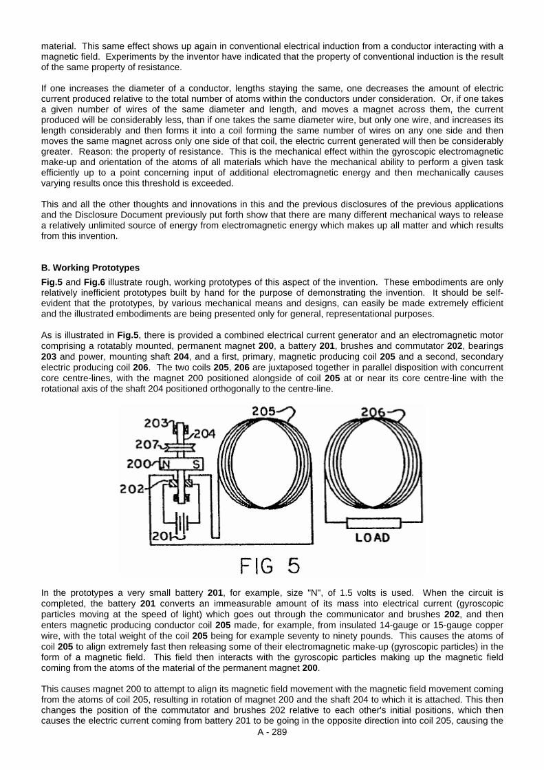
A - 289
material. This same effect shows up again in conventional electrical induction from a conductor interacting with a magnetic field. Experiments by the inventor have indicated that the property of conventional induction is the result of the same property of resistance. If one increases the diameter of a conductor, lengths staying the same, one decreases the amount of electric current produced relative to the total number of atoms within the conductors under consideration. Or, if one takes a given number of wires of the same diameter and length, and moves a magnet across them, the current produced will be considerably less, than if one takes the same diameter wire, but only one wire, and increases its length considerably and then forms it into a coil forming the same number of wires on any one side and then moves the same magnet across only one side of that coil, the electric current generated will then be considerably greater. Reason: the property of resistance. This is the mechanical effect within the gyroscopic electromagnetic make-up and orientation of the atoms of all materials which have the mechanical ability to perform a given task efficiently up to a point concerning input of additional electromagnetic energy and then mechanically causes varying results once this threshold is exceeded. This and all the other thoughts and innovations in this and the previous disclosures of the previous applications and the Disclosure Document previously put forth show that there are many different mechanical ways to release a relatively unlimited source of energy from electromagnetic energy which makes up all matter and which results from this invention. B. Working Prototypes Fig.5 and Fig.6 illustrate rough, working prototypes of this aspect of the invention. These embodiments are only relatively inefficient prototypes built by hand for the purpose of demonstrating the invention. It should be self-evident that the prototypes, by various mechanical means and designs, can easily be made extremely efficient and the illustrated embodiments are being presented only for general, representational purposes. As is illustrated in Fig.5, there is provided a combined electrical current generator and an electromagnetic motor comprising a rotatably mounted, permanent magnet 200, a battery 201, brushes and commutator 202, bearings 203 and power, mounting shaft 204, and a first, primary, magnetic producing coil 205 and a second, secondary electric producing coil 206. The two coils 205, 206 are juxtaposed together in parallel disposition with concurrent core centre-lines, with the magnet 200 positioned alongside of coil 205 at or near its core centre-line with the rotational axis of the shaft 204 positioned orthogonally to the centre-line.
In the prototypes a very small battery 201, for example, size "N", of 1.5 volts is used. When the circuit is completed, the battery 201 converts an immeasurable amount of its mass into electrical current (gyroscopic particles moving at the speed of light) which goes out through the communicator and brushes 202, and then enters magnetic producing conductor coil 205 made, for example, from insulated 14-gauge or 15-gauge copper wire, with the total weight of the coil 205 being for example seventy to ninety pounds. This causes the atoms of coil 205 to align extremely fast then releasing some of their electromagnetic make-up (gyroscopic particles) in the form of a magnetic field. This field then interacts with the gyroscopic particles making up the magnetic field coming from the atoms of the material of the permanent magnet 200. This causes magnet 200 to attempt to align its magnetic field movement with the magnetic field movement coming from the atoms of coil 205, resulting in rotation of magnet 200 and the shaft 204 to which it is attached. This then changes the position of the commutator and brushes 202 relative to each other's initial positions, which then causes the electric current coming from battery 201 to be going in the opposite direction into coil 205, causing the
A - 290
atoms of coil 205 to extremely quickly reverse their alignment and the polarity of their magnetic field which they are emitting. The reversed field then interacts again with the magnetic field of permanent magnet 200, causing it to further rotate. This process is then continuously repeated, producing continuous rotation of the shaft 204 which can be used as a source of motive power in many different ways. A power belt wheel 207 for example using a continuous "V" belt is illustrated as a general representation of this motive power source for producing useful, obvious work. In a prototype test run with a small 1.5 volt, type "N" battery, the shaft 204 and the magnet 200 - rotated at a high speed for approximately twelve hours before running down. By improving the particular design features of the prototype and by using longer lasting batteries, the rotation time of the shaft 204 can be greatly increased to a theoretical point approaching "perpetual" for all practical purposes. At the same time the alternating magnetic field produced by the coil 205 induces into coil 206 electrical induction, which then causes coil 206 to produce an alternating current across its "load," which current can be made to exceed the conventional output of the battery 201. The battery source 201 can be replaced when needed. It is very important to understand that, the longer the length of the conducting wire in coil 205, the stronger will be the magnetic field produced and the less electric current that will complete the circuit and get back into the battery and destroy the mechanical source of the electrical current. This effect can be increased further by increasing the diameter of the conducting wire in coil 205 and then greatly increasing its length still further in the coil. Reason: The gyroscopic particles making up the electric current interact with the atoms of coil 205. The more atoms in coil 205, relative to it’s length, the longer it takes the gyroparticles of the electric current to influence them and exit from the other end of the coil. It is then easily seen that if the direction of the current flowing into coil 205 is then reversed, this then further increases the lag time. Reason: The gyroscopic particles have inertia and are believed to be moving at the speed of light and they are interacting with the gyroscopic particles making up the atoms of the conducting coil 205. These atoms also have inertia, and when the direction of current in coil 205 is reversed, the incoming current then collides with the current already in coil 205 going in the opposite direction. This causes a brief hesitation during the time the current already in the coil is being forced to reverse its direction, thereby then reversing the direction of the atoms within coil 205 which have already been influenced to become aligned. This causes a constant force throughout the circuit, but does not allow very much current to get back into the battery 201 to destroy the mechanical means which initiated the release of electric current in the first place. Therefore, it should be further understood that, the faster the current direction reverses into the coil 205, the more efficiently the matter of battery 201 is converted into 2 pure electrical energy (E=MC2), without destruction of the mechanical situation that initiates the electrical current release. It is also important to understand that, the stronger the magnetic field coming from the mass of magnet 200, the greater will be its rotational speed. Additionally, the greater the magnetic field coming from the mass of coil 205, the greater will be the rotational speed of magnet 200, and, up to a point, the greater the electric current input from battery 201, the greater the rotational speed of magnet 200. Reason: the greater the electric current flow into coil 205, the greater will be the percentage of the atoms making up coil 205 that are aligned. This probably has the same relationship as does achieving atom alignment in conventional magnetic materials. Once complete atom alignment is reached in coil 205, no amount of current will cause those atoms to increase the strength of the magnetic field emitting from those atoms. Therefore, it should be clear that, for a given input of electric current from battery 201, the most efficient design is one in which the most atoms of coil 205 are influenced to atom alignment by that given electric current, which means increasing the diameter and the length of the conducting wire of coil 205 to the point that the strength of the magnetic field produced is sufficient to cause rotation of the magnet 200 to a speed that allows none or at least very little of the electric current which initially comes from the battery 201 to complete the circuit and get back into battery 201 and destroy or reduce the mechanical effect which induced the conversion of the matter of battery 201 in electric current in the first place. Again this desired effect can be increased by increasing the strength of the magnetic field given off by the atoms of the permanent magnet 200.

A - 291
In the second prototype embodiment of Fig.6, the structure and operation of the prototype is substantially identical to that of Fig.5 with the major exception being that the magnet 300/shaft 304 elements (and related sub-elements 302, 303 and 307) are positioned inside of and within the core of the primary coil 305, as compared to the placement of the magnet 200/shaft 204 elements next to and along side of the coil 205 of Fig.5. Therefore, for brevity, a detailed description of the elements of Fig.6 will not be repeated, but it is noted that the corresponding and analogous elements and sub-elements are similarly numbered in Fig.5 and Fig.6. It is also important to again stress the fact that the prototype designs shown are presented simply to prove the correctness of the invention, and it should be clear that the invention can be made extremely more efficient by utilising all of the magnetic field produced by coil 205 and designing the magnet 200 of a shape and strength that efficiently interacts with the majority of the magnetic fields from coil 205. The illustrated prototypes is relatively highly inefficient in this regard, but even so, the results of the invention itself greatly exceed the prior art as to use of electric current from whatever source and interaction with an electric motor or whatever work was conventionally performed. The applicant feels it is very important to again stress, in building many varying designs of this invention, consideration must be given to the fact that the Energy in the field of force of any type magnet is the Energy that makes up the Atoms of the material from which it comes! This Energy is a real Entity with, it is believed, a gyroscopic action. It is literally Einstein's Equation of E=MC2 and it is believed that this Energy moves at the speed of light and makes up all Matter. And that this Energy has a constant pressure effect back to the Atoms of the material from which it came, similar to hydraulic pressure. This effect is additionally more fully understood by stating the following results obtained from experimentation by the applicant in the process of this invention. a) When the system is initially attached to a 1.5 volt size N Battery 201 or 301 and the magnet 200 or 300 and related rotation entities are placed close to or in the centre of coil 205 or 305, the following results are observed: If the electric current produced in coil 206 (306) is then fed back into coil 205 (305) in accordance with proper polarity, the rotation speed of magnet 200 or 300 will then accelerate. If fed back into coil 205 (305) in wrong polarity, the rotation speed of magnet 200 (300) will slow down. This proves that the total force from coil 205 (305) interacting with the magnet 200 (300) is greater when the electrical energy from coil 206(306) is fed back into coil 205 (305), then when only the initial electric energy from battery 201 (301) is fed into coil 205 (305)! When two or three batteries are electrically connected together in series, so as to create for example three or four and a half volts of electrical input, this effect is multiplied. Remember, up to a point, the greater the electrical input, the greater the percentage of atom alignment within coil 205 (305). This further proves that the electric current produced in coil 206 (306) is a result of the gyroscopic particles of Energy released from the magnetic fields which came from the Electromagnetic make-up of the atoms of coil 205 (305), and is not part of the initial Electrical Energy released from the atoms making up the materials of battery 201 (301)! The coil 206 (306) can be taken out of the system, or its electrical current fed away from the system, and the rotational speed of the magnet 200 (300) will not observably change. However, the rotational speed of magnet 200 (300) will noticeably change when the electric current from coil 206 (306) is fed back into coil 205 (305)! Now a different result:
A - 292
b) When the electric current from battery 201 (301) becomes weaker to the point that the magnetic field coming from coil 205 (305) has weakened and shrunk allowing the magnetic field of the rotating magnet 200 (300) to expand and then noticeably induce electric current into coil 206 (306) and into coil 205 (305), then reverse results are observed. When the magnetic field from the coil 205 (305) is large, then the magnetic field from magnet 200 (300) is retained! If coil 206 (306) is then short circuited, the rotation of magnet 200 (300) will noticeably slow down. If electric current from coil 206 (306) is fed back into coil 205 (305) in wrong polarity, the rotation of the magnet 200 (300) will stop. If fed back into coil 205 (305) in correct polarity, the rotation of the magnet 200 (300) will slow down. At that point, the rotation of the magnet 200 (300) will not accelerate, no matter how connected! These results show that, at this time, the magnetic field from magnet 200 (300) noticeably induces a current in coils 206 (306) and 205 (305) which opposes the rotation of the magnet 200 (300). This effect has already been mechanically explained, and it has been shown that Lenz’s Law was simply an observation of that mechanical explanation. These results further demonstrate that the expanding and collapsing magnetic fields from coil 205 (305) and 206 (306) do not noticeably effect each other detrimentally. Because the resulting magnetic fields from all the coils are the results of fluctuating atom alignment within the coils! Remember, the gyroscopic energy particles making up the magnetic fields have a hydraulic pressure effect back to the atoms from which they came. Also remember that the atoms making up the material of the permanent magnet 200 (300) are stationary as to atom alignment direction! Therefore, the pressure effect resulting from an opposing field which the magnet 200 (300) induced, is immediate. As is Hydraulic Pressure. However, the magnetic field emitted from the atoms of coil 205 (305) relative to induction into the atoms of coil 206 (306) are fluctuating and out of step, so to speak, and therefore, in harmony with each other. The pressure effect from the induction of coil 205 (305) into coil 206 (306) is an action and reaction effect which reinforces the flipping action of the atoms of coil 205 (305) and back into the atoms of coil 206 (306). This action is again seen when the invention is hooked into one-hundred-fifteen volt alternating current, and battery 201 (301) is not used. The magnet 200 (300) will not rotate even though the magnetic field from coil 205 (305) is strong and is alternating. Reason: The fluctuating magnetic field is so fast, that the inertia mass of magnet 200 (300) can not get started in one direction before the magnetic field from coil 205 (306) has reversed, thereby, causing magnet 200 (300) to vibrate only microscopically at sixty cycles per second. And, if a sixty watt bulb is hooked into the system of coil 205 (306), it will only light dimly. And there is a lag time of two to three seconds before it lights even dimly. If then coil 206 (306) is hooked to a meter, there is a reading of forty-nine volts, and if the meter is replaced by another sixty watt bulb it will light only extremely dimly. However, the sixty watt bulb hooked to coil 205 (305) will now become noticeably brighter! This again shows that the action and reaction results of the atoms of the coils are not noticeably detrimental to each other. Because of the lag time (out of step, so to speak), resulting in reinforcing the flipping atom alignment of the coils. From this further explanation of the invention it is seen that desirable results may be obtained by the following: For example, in Fig.6 the magnet 300 may be of a design and/or be located at a distance from the inside diameter of coil 305 and coil 306, whereby the majority of the magnetic field from the magnet 300 does not cut the conducting loops of coil 305 or 306. Yet the alternating magnetic field produced by coil 305 should efficiently have the majority of its gyroscopic particles interacting with the majority of the gyroscopic particles making up the magnetic field of the permanent magnet 300, but not directly reacting with the atoms making up coil 305, or magnet 300! When the magnetic lines of force of the magnet 200 (300) cross at right angles with the conducting wires of coil 205 (305), 206 (306), a braking action is incurred. It should be noted that, as the inner diameter of coil 205 (305) increases, the percentage of time of braking effect decreases. Along this same line of instruction, the commutator segments 202 (302) can be made of a large diameter and the area of brushes made small, whereby, when the brushes cross over the gaps in the commutator segments, there will be no short circuit at any time directly back to the battery 201 (301). By combining the slip rings and brushes (the slip rings can be made of a small diameter) to the side or sides of the brushes and commutator segments 202 (302), then battery 201 (301) does not have to rotate with magnet 200 (300).
A - 293
The 14-gauge and 15-gauge insulated copper wire weighing seventy and ninety pounds respectively (31.5 kilograms and 40.5 kilograms) used for the motor coil 205 (305) and the generator coil 206 (306), respectively, in the first hand-made prototypes of the embodiments of Fig.5 and Fig.6, for demonstration purposes only, come in standard buckets of varying weights from wholesale outlets. It was then wound in coils as shown, and, as taught, the more conducting wire used, the better the results. The magnets 200 and 300 were each initially about a 2.5 inch (6.25 centimetre) cube and can be any size and strength desired. In a further, rough, hand-built, demonstration, working prototype of the invention of the type illustrated in Fig.6, the primary or motor coil 305 was made of 5-gauge copper wire in a single, continuous wire, weighing approximately 4,100 pounds (1,845 kilograms) with a coil loop diameter of 4.5 feet (135 centimetres), while the secondary or generator coil 306 was made of 24-gauge copper wire in a single continuous wire weighing approximately 300 pounds (135 kilograms) with the same, approximate coil loop diameter of 4.5 feet (135 centimetres), with both coils 305, 306 coincidentally forming a cylinder of approximately 30 inches (75 centimetres) in length. The coils 305, 306 were built around a cylindrical, fiberglass core body of approximately 200 pounds (90 kilograms) having a vertical, longitudinal centre-line axis. The rotating magnet 300 was made up of six, separate, parallel cylindrical magnetic columns spaced and disposed about the periphery of a hollow cylindrical fiberglass surface of approximately twenty inch (fifty centimetres) in diameter. Each column was 30 inches 75 cm.) long and was composed of a stack of 70, individual ceramic ring magnets in disc form as made by Jobmaster Magnets of Randallstown, Maryland, 21133, U.S.A. Each disc had a thickness of seven-sixteenths of an inch (1.09375 centimetres), an inner diameter of 1 inch (2.5 cm.) and an outer diameter of 4 inches (10 cm.). The discs were stacked and secured together in 4 inch (10 cm.) diameter fiberglass tubes longitudinally mounted on the inner surface of the twenty inch (fifty cm.) diameter fiberglass cylinder. The composite magnet 300 had a total weight of approximately 400 pounds (180 kilograms) and a total length of 30 inches (75 cm.) and an approximate diameter of 20 inches (50 cm.). The magnet 300 was mounted for rotation on a horizontal shaft 304 extending across the hollow core of the coils 305, 306 crossing through the centre point of the longitudinal centre-line of the cylinder and orthogonally to the longitudinal centre-line of the magnet 300 for rotation within the open centre area of the cylindrically disposed coils 305, 306 with the longitudinal centre-lines of the coils being vertically disposed. With a D.C. battery source 301 of two 12 volt lantern batteries and seventeen 6 volt lantern batteries all in series (totalling 126 volts), a measured voltage of 126 volts and a measured current of 99 milliamps in the primary coil 305 were noted. Concurrently a voltage reading of 640 volts and an amperage measurement in excess of 20 milliamps were noted in the secondary or generating coil 306, with the magnet 300 rotating at a speed of 120 revolutions per minute (rpm). Thus the system was outputting and producing in the generating coil 306 usable electrical energy in excess of 102% of that being inputted in the motor coil 305! This excess useful electrical energy, of course, is in addition to the further useful mechanical energy available at the exemplary drive take-off 307 on the rotating shaft 304, on which the 400 pound, 30 inch long magnet 300 was rotating at 120 rpm! Thus the invention, by utilising the energy of the gyroscopic particles in the magnetic field, produces a greater energy output than the energy input into the system, thus producing results beyond presently accepted scientific teachings of the world. This prototype achieves exactly what has already been described in great detail in applicant's prior patent applications. There was simply used in this prototype a stronger magnet and a larger diameter conducting wire of great length, that has a considerably greater number of atoms aligned when current is put into the system, and used a greater number of atoms in the generator coil of fine diameter conducting wire. While the results of the energy released from this particular prototype is highly impressive to others, the applicant still has only scratched the surface of the energy that can be released using the principles of the present invention. Again, as has already been stressed, the most efficient design, is one in which the least amount of input of current causes the greatest amount of atom alignment. These data do not constitute any departure from applicant's previous work, but is only to further document that which has already been stressed in the prior patent applications.
A - 294
Varying the D.C. voltage for the battery source 301 shows that obvious efficiency will continue to rise as the voltage input goes up! Also, the leverage factor advantage of the invention, combined with the inertia of the 400 pound magnet 300 rotating at 120 rpm (even while causing the electrical generator to put out over 100% of energy input) proves the invention to be greatly over 100% efficient even at this slow rpm. It is contemplated that the next prototype will use super-conducting type material for the coil 305 with a magnet 300 having a magnetic field strength comparable to that of crycogenic-type magnet relative to percentage of atom alignment or size. This will result in the size of the device being much smaller and yet with the available work output being much greater than the prototype just described. Reason: The most efficient type design is one whereby the least amount of current input into the motor coil produces the greatest atom alignment of said motor coil and having rotatable magnet also comparable in strength, relative to size. The invention can be made without using the coil 206 (306) and producing just useful mechanical energy. Coil 206 (306) can be merged or wound with coil 205 (305). The magnet 200 (300) can be an electromagnet, a permanent magnet, a cryogenic magnet or any magnet. The design of magnet 200 (300) can create a strong but retained magnetic field. The design of coil 205 (305) can be used to further retain the magnetic field of magnet 200 (300). Alternating current (A.C.) can be used in place of the direct current (D.C.) battery 201 (301), if the magnet 200 (300) is designed accordingly. The coils 205 (305) and 206 (306) may be made up of several coils rather than a single coil. The magnet 200 (300) may be made up of several individual magnets rather than from just a single magnet. From the foregoing it should be understood that, unlike the teachings of the prior art, the following is desired in the design of the coil 205/305 under the principles of the present invention: a) Current initially flowing into and through the coil should be small compared to the energy output of the system; b) A relatively large diameter wire or its equivalent is used for the coil; c) A relatively large number of coil loops or coils is used; d) A relative long, continuous length of coil wire or its equivalent is used; and e) The greatest magnetism for a given mass of the magnet 200/300 is desired but may be designed so that the
magnetic lines of force will not cut the coils at a right angle. The present invention applies to any mechanical device which is operated by electrical energy. In accordance with the principles of the present invention, the mechanical device should be designed wherein the electric current as much as is feasible cannot get back to its source, but the circuit is completed whereby the "pressure force" is constant throughout the system. What has been invented, built and disclosed is an invention of immense importance to the well-being of the entire world. There will be many devices built from what has been shown and taught. It should now be known that all matter is made up of electromagnetic energy and that there are many mechanical ways to release this energy, as has been stated throughout the five prior, related patent applications hereof and the Disclosure Document. All of these future developments will be as a result of the present invention which - releases energy above and beyond conventional energy release mechanisms, prior to this invention. Some of the basic approaches of the invention are outlined below: l. Any device which utilises a means by which the electric current (electromagnetic energy) is retained within a member or members outside of the source of said original electric current and then, as a result thereof, is capable of producing a continuous electromagnetic motion or current if so desired beyond present scientific teachings. 2. Any device which releases the electromagnetic energy make up of matter to such an impressive degree as does this invention that it defies several of the present accepted laws of physics and electrical engineering as of this time. 3. That the energy release is noticeably higher and in some cases more controllable than the conventional means of energy release of this time.

A - 295
Because many varying and different embodiments may be made within the scope of the inventive concept taught here, and because many modifications may be made in the embodiments detailed here in accordance with the descriptive requirements of the law, it is to be understood that the details given above are to be interpreted as illustrative and not in any limiting sense. CLAIMS 1. A usable energy generation system, comprising: usable energy output means for making available for use the usable energy generated in the system; and usable energy generation means associated with said output means and designed to take into account the
reaction to a force of the gyroscopic type energy particles and to utilise the gyroscopic type energy particles moving in a magnetic field for producing usable energy of an amount greater than the amount of energy input.
2. The system of Claim 1, wherein said generation means includes structural means for placing a force at an
angle to the gyroscopic particles causing the particles to follow paths having a net directional effect, producing electric current flow.
3. The system of Claim 2, wherein said structural means comprises magnetic means and a closed housing
associated therewith containing a fluid in the magnetic field produced by said magnetic means, said fluid becoming charged as a result of its interaction with the gyroscopic type energy particles making up said magnetic field.
4. The system of Claim 3, wherein said magnetic means is a series of aligned magnets positioned centrally within
said housing but electrically insulated therefrom. 5. The system of Claim 3, wherein there is included a further, keeper housing completely surrounding said closed
housing and electrically insulated therefrom, said keeper housing tending to keep and concentrate the magnetic field produced by said magnetic fields within it.
6. The system of Claim 3, wherein said output means includes a network of metallic surfaces immersed in said
fluid to pick up the electrical charges on said fluid. 7. The system of Claim 2, wherein said structural means comprises a member having its atoms aligned to
produce a net magnetic field which is at least substantially contained within the surface boundaries of said member.
8. The system of Claim 7, wherein said member is positioned in operative association to at least one magnet, and
said member and said magnet are held static with respect to one another. 9. The system of Claim 1, wherein: The usable energy generation system comprises an electrical energy generation system; said usable energy
output means comprises an electrical power output means; and said usable energy generation means comprises electrical energy generation means.
10. The system of Claim 1, wherein: the usable energy generation system comprises usable motion generation system; said usable energy output
means comprises usable motion output means; and said usable energy generation means comprises usable motion generation means.
11. The system of Claim 1, wherein said generation means includes: a magnetic device; a source of electrical energy; complete electrical circuit means between said magnetic device and said source of electrical energy for producing
an alternating electrical current potential; and current retarding means for retarding the flow of current through said device back to said source to the greatest
extent practical, producing a relatively small and preferably negligible current flow through said source. 12. The system of Claim 11, wherein said magnetic device includes at least one relatively large coil of wire having
a relatively large number of turns of wire of a relatively large diameter and a relatively great length. 13. The method of producing usable energy utilising a magnetic field system, comprising the following steps: a. providing a structure interacting with a magnetic field; and
A - 296
b. arranging said structure to utilise the energy of the gyroscopic type particles in the magnetic field to generate an electrical current in said structure, or usable motion from said system, or both, and results in producing a greater energy output than energy input into the system.
14. The method of Claim 13, wherein there is included in step "b" the further step of arranging said structure to
place a force at an angle to the gyroscopic particles cause the particles to follow paths having a net directional effect, producing electric current flow, without any normal, visible movement taking place in the system.
15. The method of increasing the availability of usable electrical energy or usable motion, or both, comprising the
steps of: a. providing a magnetic device for producing usable electrical energy or usable motion, which device includes a
material through which electrical current can interact producing a magnetic field which interacts with a separate mass having a magnetic field, and further providing a source of electrical energy such as for example a battery, generator, or any other;
b. providing a complete electrical circuit between said magnetic device and said source of electrical energy and producing from said source to said device an alternating electrical current potential; and
c. retarding the flow of current through said device back to said source to the greatest extent practical, producing a relatively small and preferably negligible current flow through said source and resulting in electrical energy output, or usable motion output, being a greater energy output than energy input into the device.
16. The method of Claim 15, wherein step "c" is achieved at least in part by the step of providing in said device a
relatively large coil or coils of wire having a relatively large number of turns of wire of a relatively large diameter and a relatively great length.
17. The method of Claim 15, wherein step "c" is achieved at least in part by the step of utilising a means by which
the electric current is retained within at least one member outside of the source of said original electric current and then, as a result thereof, is capable of producing a continuous electromagnetic motion or current.
18. The method of claim 15, wherein there is included the step of providing a separate magnetic source
positioned so that its magnetic lines of force avoid significantly cutting the material through which the electrical energy flows avoiding a braking effect which would retard the desired motion of said magnetic source.
19. The method of Claim 15, wherein step "a" is achieved by said material being a super conducting material and
said separate magnetic mass is at least equivalent to a cryogenic magnet. 20. The method of Claim 15, wherein step "a" is achieved by the step of having said material a conducting
material and said separate magnetic mass of any desired configuration or strength or type. 21. The method of increasing the availability of usable electrical energy, or usable motion, or both, comprising the
steps of: a. providing a magnetic device which has a material mass into which an electrical current is introduced, by any
desired means, which results in causing pertinent atom alignment, within said material mass, thereby releasing some of the electromagnetic energy making up the atoms of said material mass, in the form of a magnetic field, which then causes the gyroscopic type energy particles of said magnetic field to then interact with the gyroscopic type energy particles making up a magnetic field coming from the atoms of a different material mass; and
b. having the magnetic device then cause a release of electrical current or usable motion or both through at least one power outlet and resulting in producing a greater energy output than energy input into the device.
22. The method of Claim 21, wherein the material mass or masses are made of a material or substance that
allows for extremely fast atom alignment, without the delay, or conventional degree of hysteresis losses normally associated with conventional iron atom alignment.
23. A device which increases the availability of usable electrical energy or usable motion, or both, by causing the
atoms of a material or materials to release some of their magnetic energy makeup in the form of a magnetic field, consisting of gyroscopic type energy particles which make up the atoms of the material from which the magnetic field comes; and
a properly designed mechanism, or power output arrangement being place to utilise the energy of said gyroscopic type energy particles, causing a release of energy output greater than energy input without producing radioactive material.
24. A device which increases the availability of usable electrical energy or usable motion, or both, from a given
mass or masses by a device causing a controlled release of, or reaction to, the gyroscopic type energy

A - 297
particles making up or coming from the atoms of the mass or masses, which in turn, by any properly designed system, causes an energy output greater than the energy input.
25. A system including an energy generator, motor, etc. of any design or mechanism that takes into account- the reaction to a force of the gyroscopic type energy particles
moving in a magnetic field at tremendous speeds which releases greater output than energy input. 26. The system of Claim 25, wherein a small input of electrical current into the mechanism causes extremely
quick and high atom alignment, resulting from using a super conducting material, thereby creating a powerful magnetic field, whereby its gyroscopic type energy particles then interact with the gyroscopic type energy particles coming from a second powerful magnetic field and results in producing a greater output of energy than input of energy into the mechanism.
27. The system of Claim 25, wherein a structure is arranged, whereby, there is, or will be, a pressure, or force,
exerted on or in said structure, thereby causing the atoms of said structure to react to said pressure or force, and as a result take a pertinent atom alignment direction that results in said atoms of said structure then causing the gyroscopic type energy particles moving in the magnetic field to be generally deflected in the same direction through said structure, which results in usable electric current flow, producing a greater energy output, than energy input into the system.
28. The system of Claim 25, wherein a rotary magnetic mass is designed to react to a reversing magnetic field of
another mass, and said reversing magnetic field can not reverse any faster than the atoms of said other mass can flip and realign; said rotary magnet mass being made as long as is practical to adjust to this requirement, wherein the distance of the arc of circle travelled by the ends of said rotary magnet mass is great; great leverage from said reversible magnetic field of other mass being applied to said rotary magnet, and in addition the increased distance of arc travelled by the ends of rotary magnet before the magnetic field of said other mass reverses, greatly increasing the time in which a maximum force is exerted by the gyroscopic type energy particles moving in the magnetic field coming from the maximum number of atoms aligned in said other mass, thereby causing a longer time of acceleration of said rotatable magnet mass before the atoms of said other mass are required to reverse.
29. The method of producing usable energy, comprising the following steps:
a. imputing energy into a device from an external source; b. having electrical current flow within said device; and c. utilising the internal electromagnetic energy of at least some of the matter in the device to add to the energy
being imputed into the device from the external source to produce useful energy for use outside of the device having an amount greater than the energy being imputed to the device.
A - 298
PHILIP BRODY: FERROELECTRIC CERAMIC DEVICES
Patent US 4,041,465 27th September 1977 Inventor: Philip S. Brody
Assignee: The Unites States of America as represented by the Secretary of the Army
FERROELECTRIC CERAMIC DEVICES This version of the patent has been re-worded in an attempt to make it easier to read and understand. The original can be examined at www.freepatentsonline.com and downloaded without charge. This patent covers several different applications, namely; a high-voltage very high-efficiency solar electric device, a photovoltaic memory device, an optical display device and a high-voltage battery, to name just a few. It should be noted that this patent is assigned to the US Army. In my opinion, that lends weight and credibility to this patent. It is claimed that a one centimetre square piece of this material can produce 1,500 volts as opposed to less than one volt using conventional solar cell materials. ABSTRACT A method and apparatus is disclosed by which high voltage and current can produced by a polycrystalline ferroelectric ceramic material in response to incident light. Numerous applications of the ferroelectric ceramic material taking advantage of such properties thereof are further disclosed. The polycrystalline ferroelectric ceramic material is initially poled by the application of a pulse of voltage of predetermined magnitude and direction. After being poled in such fashion, light shining on the various surfaces of the ferroelectric ceramic material will generate a consistent high voltage between the surfaces of the ferroelectric ceramic material. If electrodes are attached to the material, then a current will be generated and a load can then be powered by it. Importantly, the magnitude of the voltage produced by the light is directly proportional to the remanent polarisation of the ferroelectric ceramic material, and is further directly proportional to the length of the material, the polarity of the high voltage being dependent upon the polarity of the remanent polarisation and being capable of being reversed when the remanent polarisation is reversed. The open circuit voltages produced by the ferroelectric ceramic material are orders of magnitude higher than those which typically have been produced in the prior-art through the utilisation of standard photovoltaic materials. DESCRIPTION BACKGROUND OF THE INVENTION This invention generally relates to solid state devices exhibiting photovoltaic effects and is particularly directed to the provision of a device consisting of a class of polycrystalline ferroelectric ceramic materials which have been discovered to produce voltages upon the application of light. These voltages are many orders of magnitude higher than voltages typically produced by conventional photovoltaic materials. Initially, and as background, the instant inventive apparatus and techniques to be discussed below are to be clearly distinguished from the photovoltaic effect now know in the prior-art in that the mechanism for the effect to be discussed herein appears to be unique and different from photovoltaic mechanisms previously described. SUMMARY OF THE INVENTION It is the primary objective of the instant invention to provide a device and technique by which extremely high voltage can be generated utilising a solid state polycrystalline class of materials upon the application to such materials of incident light, the voltage generated exhibiting properties entirely unlike the well-known photovoltaic effect of the prior art and of orders of magnitude higher than voltages previously obtainable. Another equally important objective of the instant invention is the provision of apparatus utilising ferroelectric ceramic materials of the type to be described below, such apparatus taking advantage of the unique properties as discovered to be existent in the class of materials to which the instant invention relates. These broad objectives, as well as others which will become apparent as the following description proceeds, are implemented by the subject invention which utilises at its heart a class of materials known as ferroelectric

A - 299
ceramics, and which take advantage of the unique photovoltaic properties discovered to be existent in such class of materials. Specifically, by illuminating the surfaces of these materials, a steady voltage results across conducting electrodes placed in contact therewith. Currents can then be drawn through loads placed across these electrodes. It has been discovered that an arrangement of an initially polarised ceramic material with electrodes attached thereto as is shown in Fig.1 of the application drawings produces steady high voltages from a steady illuminating source such as the sun, an incandescent bulb, a fluorescent tube, etc. and that the magnitude of these voltages is high and directly proportional to the length, l of the sheet of material provided. In Fig.1, the shaded area represents an electrode, and Pr is the remanent polarisation. In another basic arrangement of the invention, light enters through transparent electrodes and the material is poled in the direction of the light, and the photo-emf up to a certain limiting thickness is proportional to the thickness of the slab. It has further been discovered that the magnitude of the photo-voltages produced is directly proportional to the remanent polarisation of the material. The polarity of the photo-voltage is dependent on the polarity of the remanent polarisation and reverses when the remanent polarisation is reversed. The magnitude of the voltages that are produced can also be varied by varying the sizes of the grains of which the ceramic is composed, the voltage having a generally proportional relation to the number of grains per unit length. Grain size can be controlled by well-known fabrication techniques involving compositional additives and firing rates, which techniques do not form a part of the present disclosure. When illuminated at intensity levels such as that produced by direct sunlight or at lesser levels such as that produced by a fluorescent lamp, the materials will behave as voltage sources in series with a high output resistance. The output resistance will decrease an the intensity of illumination increases and also varies with wavelength. The open circuit voltages produced by the materials of the invention are much higher than those that are typical of other photovoltaic materials. These high open circuit photo-voltages have been observed to some extent in virtually all materials examined which can generally be described or classified by the term ferroelectric ceramic, provided that the material was characterised by a net remanent polarisation. Such high photo-voltages are to be expected in virtually all polarised ferroelectric ceramic materials properly doped, the class including thousands of different known materials of this kind with numerous variations possible in each kind. Such variations are produced by additives, varying grain size, and by changing compositional blends, in those formed from mixtures. Any of these are expected to have application as photovoltaic materials. From the viewpoint of application, the novel photovoltaic effect seen in ferroelectrics in accordance with the teachings herein differs in two important respects from the well known junction photovoltaic effect which is the mechanism in prior-art devices such as solar cells, and photo-diodes. First, the prior-art junction photo-emf is independent of the length or thickness of the unit and is low, less than one volt. To obtain high voltages, many cells have to be connected in series. The photovoltaic effect in ferroelectrics, on the other hand, can be used to directly produce high voltages. The photo-emf is proportional to length, and the photo-emf per unit length can be very high. For example, the composition Pb(Zr65Ti35)O3 with 7% of the lead substituted by lanthanum, when composed of 2-4 microns grains produces, when illuminated as shown in Fig.1, 1500 volts for every centimetre of length between the electrodes. A single one cm square unit thus directly produces 1500 volts. In this case, it is also clear that the voltage per unit length will be further increased by the development of a composition in which the average grain size is further decreased. These voltages are so high that applications have been contemplated which are alternatives to the devices presently used for the generation of extremely high DC voltages at low currents -- such as belt machines (the Van de Graaf), in which high voltages are produced by mechanically moving electric charges. Second, and perhaps even more important, is the fact that the direction of the photo-current and photo-voltage can be reversed simply by reversing the direction of its remanent polarisation. The magnitude of these quantities can be changed by changing that of the remanent polarisation, which in turn can be done (for example) by applying the proper polarity electrical voltage (poling voltage) to the same terminals across which the photo-voltages appear. The reversibility and control provided make immediately possible applications to use in computer memories of a new type -- in which information is stored as remanent polarisation and read out as the polarity and magnitude of a photo-current or photo-emf, such typical applications are disclosed here. Application to the generation of electrical power from solar radiation, for example, to solar battery type devices and to electrical power generating stations operating on the basis of solar to electrical energy conversion also is
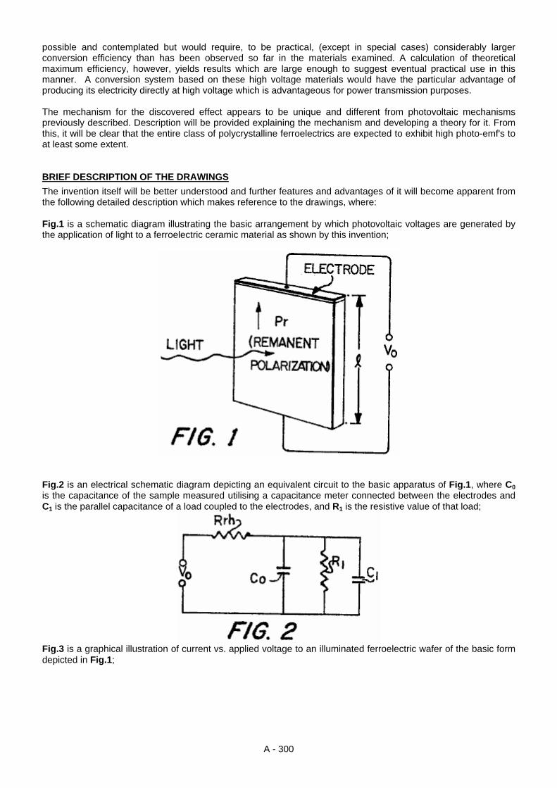
A - 300
possible and contemplated but would require, to be practical, (except in special cases) considerably larger conversion efficiency than has been observed so far in the materials examined. A calculation of theoretical maximum efficiency, however, yields results which are large enough to suggest eventual practical use in this manner. A conversion system based on these high voltage materials would have the particular advantage of producing its electricity directly at high voltage which is advantageous for power transmission purposes. The mechanism for the discovered effect appears to be unique and different from photovoltaic mechanisms previously described. Description will be provided explaining the mechanism and developing a theory for it. From this, it will be clear that the entire class of polycrystalline ferroelectrics are expected to exhibit high photo-emf's to at least some extent. BRIEF DESCRIPTION OF THE DRAWINGS The invention itself will be better understood and further features and advantages of it will become apparent from the following detailed description which makes reference to the drawings, where: Fig.1 is a schematic diagram illustrating the basic arrangement by which photovoltaic voltages are generated by the application of light to a ferroelectric ceramic material as shown by this invention;
Fig.2 is an electrical schematic diagram depicting an equivalent circuit to the basic apparatus of Fig.1, where C0 is the capacitance of the sample measured utilising a capacitance meter connected between the electrodes and C1 is the parallel capacitance of a load coupled to the electrodes, and R1 is the resistive value of that load;
Fig.3 is a graphical illustration of current vs. applied voltage to an illuminated ferroelectric wafer of the basic form depicted in Fig.1;
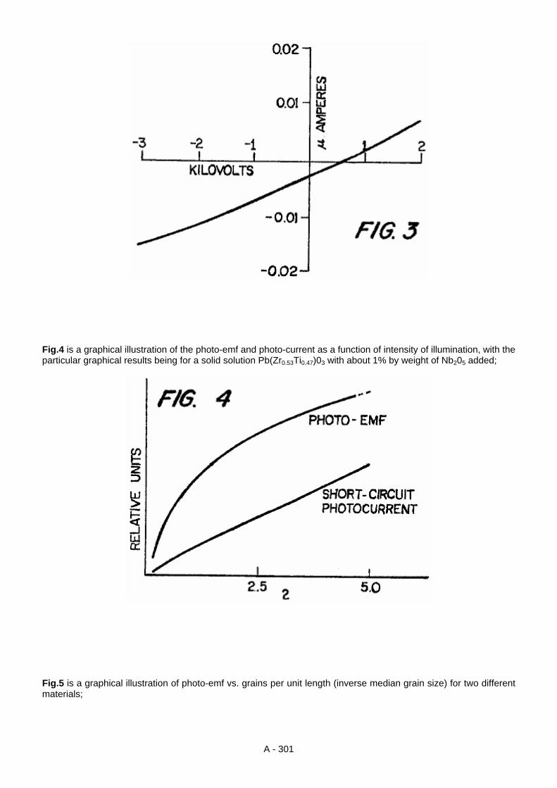
A - 301
Fig.4 is a graphical illustration of the photo-emf and photo-current as a function of intensity of illumination, with the particular graphical results being for a solid solution Pb(Zr0.53Ti0.47)03 with about 1% by weight of Nb205 added;
Fig.5 is a graphical illustration of photo-emf vs. grains per unit length (inverse median grain size) for two different materials;

A - 302
Fig.6 is a graphical illustration of photo-voltage vs. remanent polarisation for ceramic BaTi03 + 5% by weight of CaTi03 ;
Fig.7 is a diagram illustrating the short-circuit photo-current as a function of wavelength for the solid solution Pb(Zr0.53Ti0.47)03 ;

A - 303
Fig.8 is a diagram illustrating the short circuit photo-current as a function of wave length for ceramic BaTi03 + 5% by weight of CaTi03 ;
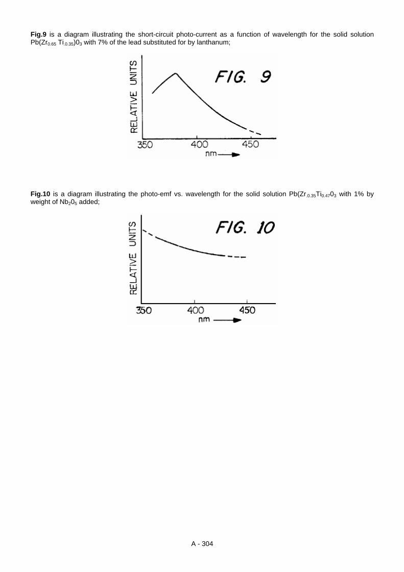
A - 304
Fig.9 is a diagram illustrating the short-circuit photo-current as a function of wavelength for the solid solution Pb(Zr0.65 Ti.0.35)03 with 7% of the lead substituted for by lanthanum;
Fig.10 is a diagram illustrating the photo-emf vs. wavelength for the solid solution Pb(Zr.0.35Ti0.4703 with 1% by weight of Nb205 added;

A - 305
Fig.11 is a diagram illustrating the photo-current divided by intensity vs. cut-off wave length of long wave length cut-off dichroic filters, with the materials being Pb(Zr0.53 Ti.0.47)03 with 1% by weight of Nb205 added and utilising a high-pressure mercury arc as the illumination source;
Fig.12 is a diagram illustrating the photo-current divided by intensity vs. cut-off wavelength of short wave length cut-off filters, with the material being Pb(Zr0.53 Ti.0.47)03 with 1% by weight of Nb205 added;

A - 306
Fig.13, is diagram illustrating the photo-emf vs. wave length of short wavelength cut-off filters, with the material being Pb(Zr0.53 Ti.0.47)03 with 1% by weight of Nb205 added;
Fig.14 is a pictorial illustration of the manner in which a single crystal produces a photo-emf, with the polarisation Ps being normal to the electrodes, which electrodes are illustrated by the shaded area;
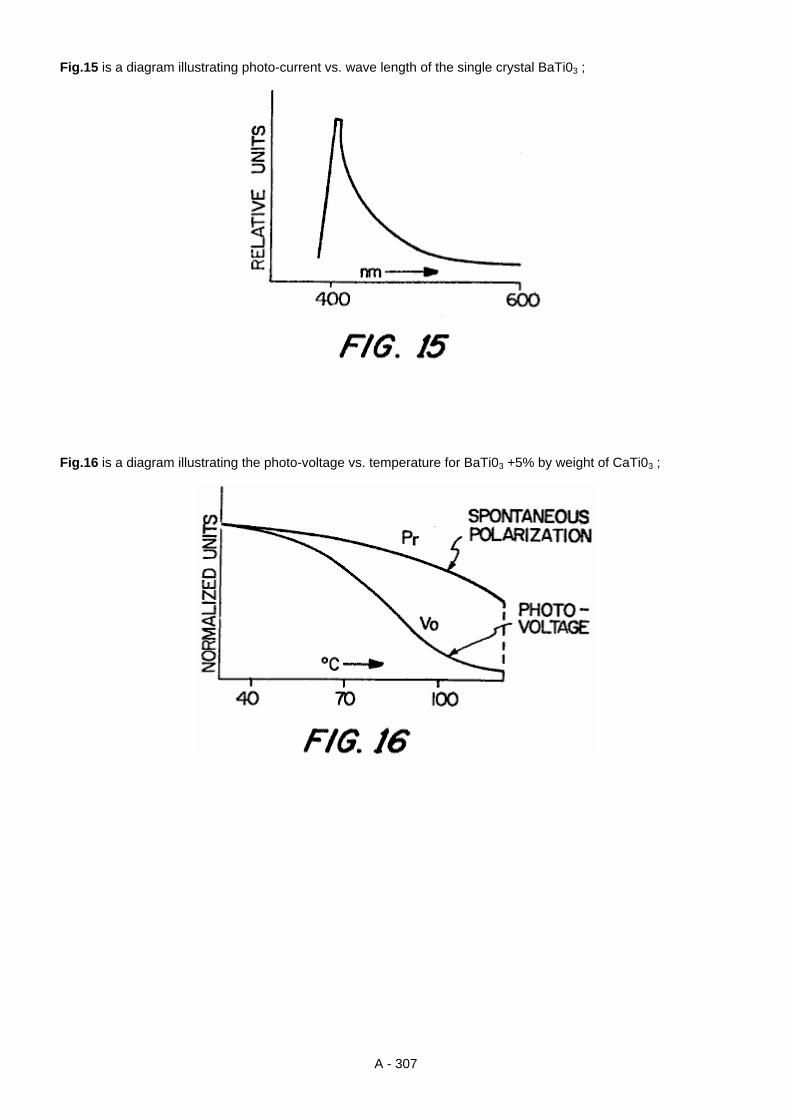
A - 307
Fig.15 is a diagram illustrating photo-current vs. wave length of the single crystal BaTi03 ;
Fig.16 is a diagram illustrating the photo-voltage vs. temperature for BaTi03 +5% by weight of CaTi03 ;
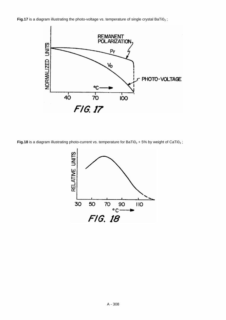
A - 308
Fig.17 is a diagram illustrating the photo-voltage vs. temperature of single crystal BaTi03 ;
Fig.18 is a diagram illustrating photo-current vs. temperature for BaTi03 + 5% by weight of CaTi03 ;
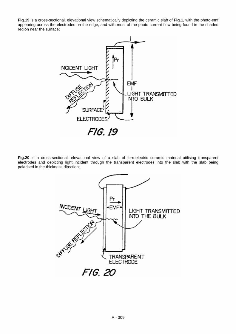
A - 309
Fig.19 is a cross-sectional, elevational view schematically depicting the ceramic slab of Fig.1, with the photo-emf appearing across the electrodes on the edge, and with most of the photo-current flow being found in the shaded region near the surface;
Fig.20 is a cross-sectional, elevational view of a slab of ferroelectric ceramic material utilising transparent electrodes and depicting light incident through the transparent electrodes into the slab with the slab being polarised in the thickness direction;
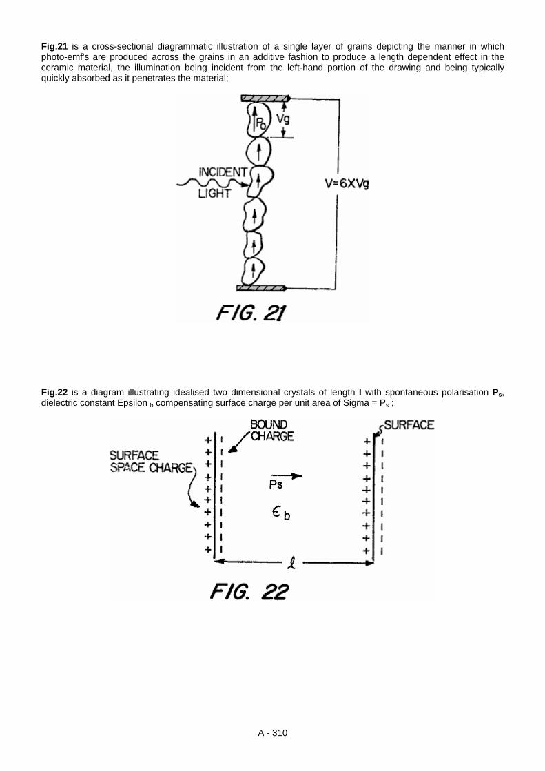
A - 310
Fig.21 is a cross-sectional diagrammatic illustration of a single layer of grains depicting the manner in which photo-emf's are produced across the grains in an additive fashion to produce a length dependent effect in the ceramic material, the illumination being incident from the left-hand portion of the drawing and being typically quickly absorbed as it penetrates the material;
Fig.22 is a diagram illustrating idealised two dimensional crystals of length l with spontaneous polarisation Ps, dielectric constant Epsilon b compensating surface charge per unit area of Sigma = Ps ;

A - 311
Fig.23 is an illustration depicting the structure of a typical ferroelectric grain or crystallite;
Fig.24 is an illustration depicting a model of a crystal of length l;
Fig.25 is a diagram illustrating the potential distribution in an illuminated crystal;
Fig.26 is a schematic representation of the instant inventive ferroelectric ceramic substrate utilised as a photovoltaic memory device with optical scanning;
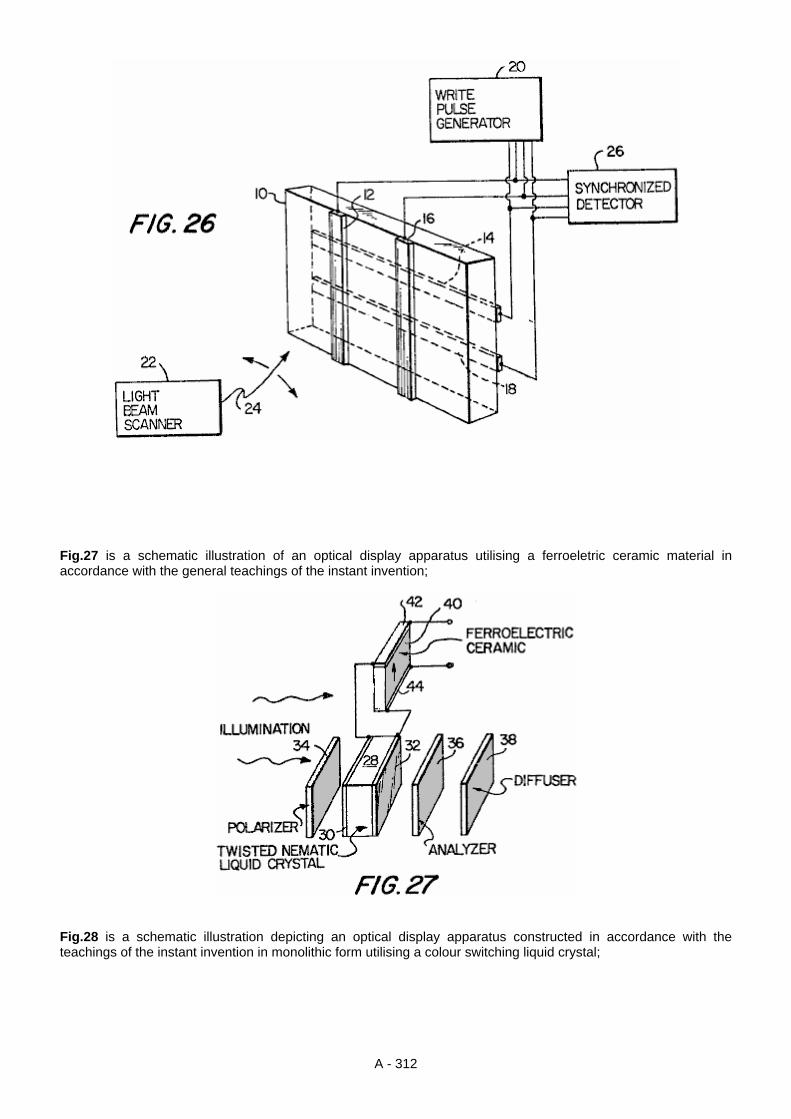
A - 312
Fig.27 is a schematic illustration of an optical display apparatus utilising a ferroeletric ceramic material in accordance with the general teachings of the instant invention;
Fig.28 is a schematic illustration depicting an optical display apparatus constructed in accordance with the teachings of the instant invention in monolithic form utilising a colour switching liquid crystal;
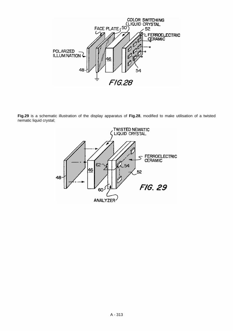
A - 313
Fig.29 is a schematic illustration of the display apparatus of Fig.28, modified to make utilisation of a twisted nematic liquid crystal;

A - 314
Fig.30 is a cross-sectional elevational view depicting an optical display apparatus utilising a colour switching liquid crystal in conjunction with a ferroelectric ceramic substrate of the instant invention, and which display apparatus exhibits permanent memory capabilities;
Fig.31 is a cross-sectional elevational view of a further form of an optical display apparatus constructed in accordance with the teachings of the instant invention, said apparatus utilising a colour switching liquid crystal and further utilising length-wise polarisation of the ceramic substrate;
Fig.32 is an elevational view, in section, of a further form of an optical display apparatus constructed in accordance with the teachings of the instant invention, this apparatus being similar to that depicted in Fig.31 of the application drawings but utilising a liquid crystal of the twisted nematic type; and

A - 315
Fig.33 is a schematic illustration of a further form of optical display and storage utilising the photoconductive as well as photovoltaic properties of the ferroelectric ceramics.

A - 316
Fig.34 illustrates how the image stored in a substrate is displayed.
DETAILED DESCRIPTION OF THE PREFERRED INVENTIVE EMBODIMENTS With reference now initially to Fig.1 of the application drawings, a discussion of the novel phenomena of the instant invention will ensue. Upon the application of incident illumination to the ferroelectric ceramic, a steady voltage is produced which is proportional to the length l between the electrodes. By dividing the sample into two equal segments along a line perpendicular to the direction of the remanent polarisation and by placing new electrodes on the cut edges, new samples would result each producing photo-emf's which is one half the original photo-emf. An arrangement such as that shown in Fig.1 can be described roughly by the equivalent circuit as shown in Fig.2. This has a saturation photo-emf Vo, in series with the photo resistance of the illuminated sample. Fig.3 is a current-voltage characteristic of a typical illuminated ferroelectric slab, and has the form expected from the equivalent circuit in Fig.2 except for the slight tendency towards saturation in the lower left quadrant. As a function of intensity, the photo-emf saturates at relatively low levels of illumination. The short circuit photo-current is, however, linear with light intensity. Results for the material Pb(Zr0.53Ti0.47)03 with 1% by weight of Nb205 are shown in Fig.4. The implication of these results and the equivalent circuit in Fig.2 is that the photo-resistance Rph is inversely proportional to intensity. A saturation photo-emf and a short circuit current proportional to intensity has been measured in several poled ferroelectric materials. These are shown in Table I:
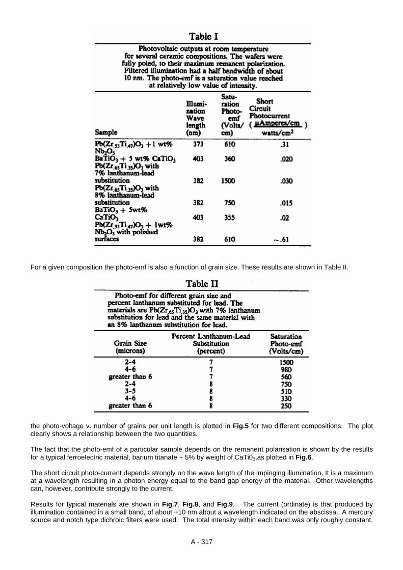
A - 317
For a given composition the photo-emf is also a function of grain size. These results are shown in Table II.
the photo-voltage v. number of grains per unit length is plotted in Fig.5 for two different compositions. The plot clearly shows a relationship between the two quantities. The fact that the photo-emf of a particular sample depends on the remanent polarisation is shown by the results for a typical ferroelectric material, barium titanate + 5% by weight of CaTi03,as plotted in Fig.6. The short circuit photo-current depends strongly on the wave length of the impinging illumination. It is a maximum at a wavelength resulting in a photon energy equal to the band gap energy of the material. Other wavelengths can, however, contribute strongly to the current. Results for typical materials are shown in Fig.7, Fig.8, and Fig.9. The current (ordinate) is that produced by illumination contained in a small band, of about +10 nm about a wavelength indicated on the abscissa. A mercury source and notch type dichroic filters were used. The total intensity within each band was only roughly constant.
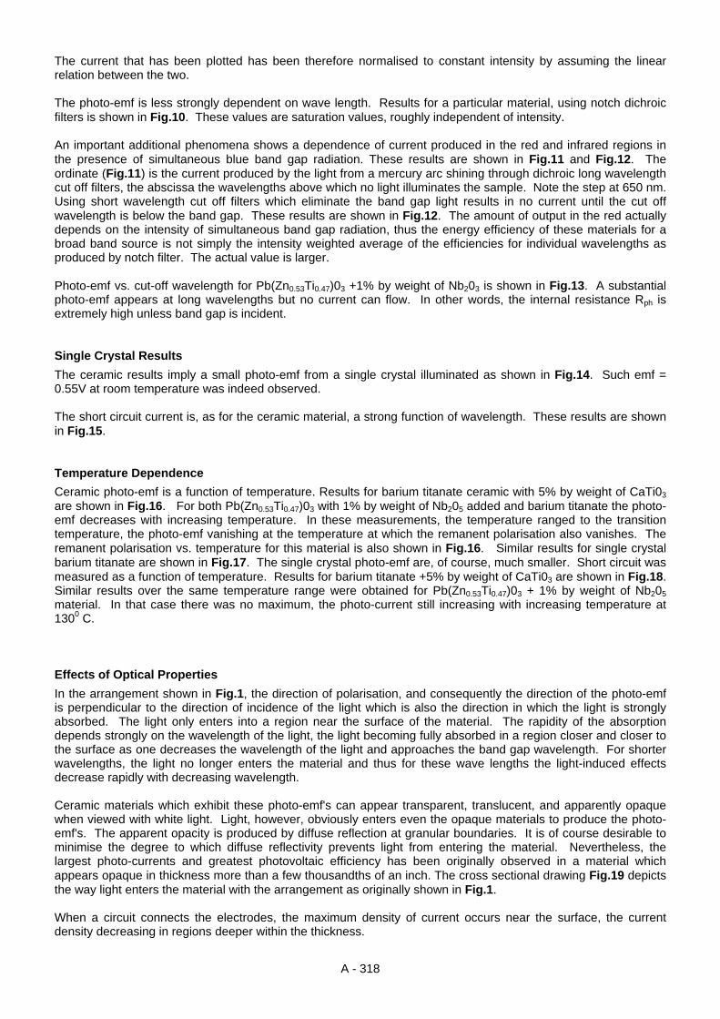
A - 318
The current that has been plotted has been therefore normalised to constant intensity by assuming the linear relation between the two. The photo-emf is less strongly dependent on wave length. Results for a particular material, using notch dichroic filters is shown in Fig.10. These values are saturation values, roughly independent of intensity. An important additional phenomena shows a dependence of current produced in the red and infrared regions in the presence of simultaneous blue band gap radiation. These results are shown in Fig.11 and Fig.12. The ordinate (Fig.11) is the current produced by the light from a mercury arc shining through dichroic long wavelength cut off filters, the abscissa the wavelengths above which no light illuminates the sample. Note the step at 650 nm. Using short wavelength cut off filters which eliminate the band gap light results in no current until the cut off wavelength is below the band gap. These results are shown in Fig.12. The amount of output in the red actually depends on the intensity of simultaneous band gap radiation, thus the energy efficiency of these materials for a broad band source is not simply the intensity weighted average of the efficiencies for individual wavelengths as produced by notch filter. The actual value is larger. Photo-emf vs. cut-off wavelength for Pb(Zn0.53Ti0.47)03 +1% by weight of Nb203 is shown in Fig.13. A substantial photo-emf appears at long wavelengths but no current can flow. In other words, the internal resistance Rph is extremely high unless band gap is incident. Single Crystal Results The ceramic results imply a small photo-emf from a single crystal illuminated as shown in Fig.14. Such emf = 0.55V at room temperature was indeed observed. The short circuit current is, as for the ceramic material, a strong function of wavelength. These results are shown in Fig.15. Temperature Dependence Ceramic photo-emf is a function of temperature. Results for barium titanate ceramic with 5% by weight of CaTi03 are shown in Fig.16. For both Pb(Zn0.53Ti0.47)03 with 1% by weight of Nb205 added and barium titanate the photo-emf decreases with increasing temperature. In these measurements, the temperature ranged to the transition temperature, the photo-emf vanishing at the temperature at which the remanent polarisation also vanishes. The remanent polarisation vs. temperature for this material is also shown in Fig.16. Similar results for single crystal barium titanate are shown in Fig.17. The single crystal photo-emf are, of course, much smaller. Short circuit was measured as a function of temperature. Results for barium titanate +5% by weight of CaTi03 are shown in Fig.18. Similar results over the same temperature range were obtained for Pb(Zn0.53Ti0.47)03 + 1% by weight of Nb205 material. In that case there was no maximum, the photo-current still increasing with increasing temperature at 1300 C. Effects of Optical Properties In the arrangement shown in Fig.1, the direction of polarisation, and consequently the direction of the photo-emf is perpendicular to the direction of incidence of the light which is also the direction in which the light is strongly absorbed. The light only enters into a region near the surface of the material. The rapidity of the absorption depends strongly on the wavelength of the light, the light becoming fully absorbed in a region closer and closer to the surface as one decreases the wavelength of the light and approaches the band gap wavelength. For shorter wavelengths, the light no longer enters the material and thus for these wave lengths the light-induced effects decrease rapidly with decreasing wavelength. Ceramic materials which exhibit these photo-emf's can appear transparent, translucent, and apparently opaque when viewed with white light. Light, however, obviously enters even the opaque materials to produce the photo-emf's. The apparent opacity is produced by diffuse reflection at granular boundaries. It is of course desirable to minimise the degree to which diffuse reflectivity prevents light from entering the material. Nevertheless, the largest photo-currents and greatest photovoltaic efficiency has been originally observed in a material which appears opaque in thickness more than a few thousandths of an inch. The cross sectional drawing Fig.19 depicts the way light enters the material with the arrangement as originally shown in Fig.1. When a circuit connects the electrodes, the maximum density of current occurs near the surface, the current density decreasing in regions deeper within the thickness.
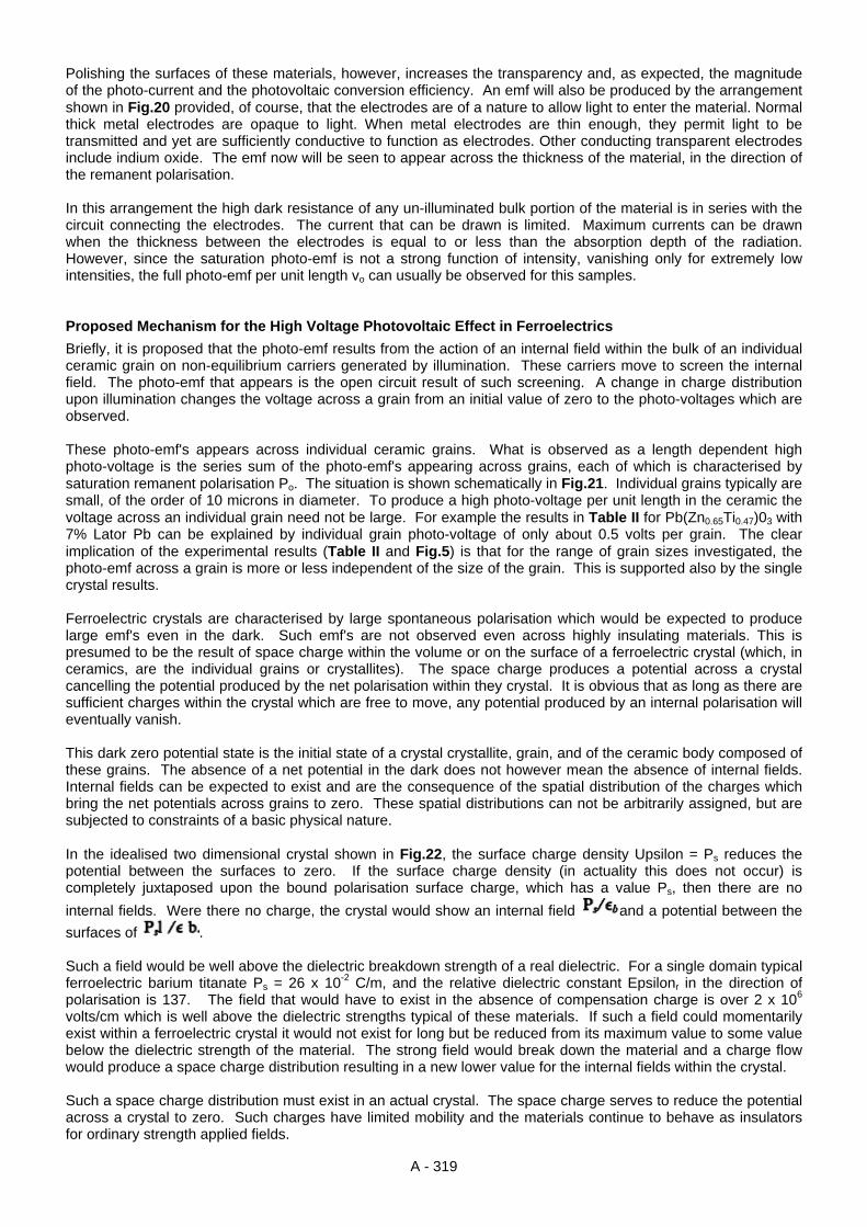
A - 319
Polishing the surfaces of these materials, however, increases the transparency and, as expected, the magnitude of the photo-current and the photovoltaic conversion efficiency. An emf will also be produced by the arrangement shown in Fig.20 provided, of course, that the electrodes are of a nature to allow light to enter the material. Normal thick metal electrodes are opaque to light. When metal electrodes are thin enough, they permit light to be transmitted and yet are sufficiently conductive to function as electrodes. Other conducting transparent electrodes include indium oxide. The emf now will be seen to appear across the thickness of the material, in the direction of the remanent polarisation. In this arrangement the high dark resistance of any un-illuminated bulk portion of the material is in series with the circuit connecting the electrodes. The current that can be drawn is limited. Maximum currents can be drawn when the thickness between the electrodes is equal to or less than the absorption depth of the radiation. However, since the saturation photo-emf is not a strong function of intensity, vanishing only for extremely low intensities, the full photo-emf per unit length vo can usually be observed for this samples. Proposed Mechanism for the High Voltage Photovoltaic Effect in Ferroelectrics Briefly, it is proposed that the photo-emf results from the action of an internal field within the bulk of an individual ceramic grain on non-equilibrium carriers generated by illumination. These carriers move to screen the internal field. The photo-emf that appears is the open circuit result of such screening. A change in charge distribution upon illumination changes the voltage across a grain from an initial value of zero to the photo-voltages which are observed. These photo-emf's appears across individual ceramic grains. What is observed as a length dependent high photo-voltage is the series sum of the photo-emf's appearing across grains, each of which is characterised by saturation remanent polarisation Po. The situation is shown schematically in Fig.21. Individual grains typically are small, of the order of 10 microns in diameter. To produce a high photo-voltage per unit length in the ceramic the voltage across an individual grain need not be large. For example the results in Table II for Pb(Zn0.65Ti0.47)03 with 7% Lator Pb can be explained by individual grain photo-voltage of only about 0.5 volts per grain. The clear implication of the experimental results (Table II and Fig.5) is that for the range of grain sizes investigated, the photo-emf across a grain is more or less independent of the size of the grain. This is supported also by the single crystal results. Ferroelectric crystals are characterised by large spontaneous polarisation which would be expected to produce large emf's even in the dark. Such emf's are not observed even across highly insulating materials. This is presumed to be the result of space charge within the volume or on the surface of a ferroelectric crystal (which, in ceramics, are the individual grains or crystallites). The space charge produces a potential across a crystal cancelling the potential produced by the net polarisation within they crystal. It is obvious that as long as there are sufficient charges within the crystal which are free to move, any potential produced by an internal polarisation will eventually vanish. This dark zero potential state is the initial state of a crystal crystallite, grain, and of the ceramic body composed of these grains. The absence of a net potential in the dark does not however mean the absence of internal fields. Internal fields can be expected to exist and are the consequence of the spatial distribution of the charges which bring the net potentials across grains to zero. These spatial distributions can not be arbitrarily assigned, but are subjected to constraints of a basic physical nature. In the idealised two dimensional crystal shown in Fig.22, the surface charge density Upsilon = Ps reduces the potential between the surfaces to zero. If the surface charge density (in actuality this does not occur) is completely juxtaposed upon the bound polarisation surface charge, which has a value Ps, then there are no internal fields. Were there no charge, the crystal would show an internal field and a potential between the surfaces of . Such a field would be well above the dielectric breakdown strength of a real dielectric. For a single domain typical ferroelectric barium titanate Ps = 26 x 10-2 C/m, and the relative dielectric constant Epsilonr in the direction of polarisation is 137. The field that would have to exist in the absence of compensation charge is over 2 x 10⁶ volts/cm which is well above the dielectric strengths typical of these materials. If such a field could momentarily exist within a ferroelectric crystal it would not exist for long but be reduced from its maximum value to some value below the dielectric strength of the material. The strong field would break down the material and a charge flow would produce a space charge distribution resulting in a new lower value for the internal fields within the crystal. Such a space charge distribution must exist in an actual crystal. The space charge serves to reduce the potential across a crystal to zero. Such charges have limited mobility and the materials continue to behave as insulators for ordinary strength applied fields.

A - 320
Such a space charge cannot occupy a delta function-like region as in the idealised situation shown in Fig.22, but must occupy instead a finite volume. If these are localised near the surface of the crystal, then an internal field Epsilonb exists within the bulk of the material and additional fields Es exist within the space charge regions near the surface. It is hypothesised that these space charge regions are near the surface of real crystals with the charge distributed within a surface layer thickness s. The reasons for same are as follows: (1) The surface regions of ferroelectric crystals are characterised by regions whose dielectric, ferroelectric, and
thermodynamic properties differ markedly from that of the bulk. These differences are best explained by the existence of strong fields in this region that would be produced by space charge. There is a considerable body of information in the literature supporting the existence and delineating the properties of these layers;
(2) The interplay of space charge and the very non-linear dielectric constant of ferroelectric would be expected to localise space charge in a low dielectric constant layer near the surface. In ferroelectrics, unusually high, low field relative dielectric constants (of the order of 1000) can be expected to reduce in value with increasing field strength. Thus charge in a region reduces the dielectric constant of that region increasing the field strength of that region. This feedback mechanism can be shown to localise charge within a layer.
The experimental results supporting the existence of surface layers will not be reviewed here, nor the calculations which support the localisation of charge into layers as a result of a non-linear (saturable) dielectric constant. These may be reviewed by referring to the literature. A schematic description of a typical grain, i.e. crystallite, with space charge regions of thickness s, and a bulk region of thickness l, is shown in Fig.23. The internal fields (in the two dimensional model) of such a charge distribution superimposed on that produced by the bound polarisation charge will be calculated and also the effect of these fields on carriers within the bulk produced as the result of an internal photo effect (photo-ionisation). Formulae for the photo emf that will be derived will have the correct sign, a linear dependence on remanent polarisation, and the kind of temperature dependence that has actually been observed. In addition there will result an estimate of a size independent grain photo-emf for a typical ferroelectric, barium titanate, which is consistent with that implied from the observed ceramic emf, and single grain emf. The grain has as shown in Fig.23: (1) A bulk region with dielectric constant Epsilonb and uniform polarisation (at zero applied field) Po ; (2) Surface layers of dielectric constant Epsilons, considerably less than that of the bulk. There are also
polarisation in the surface regions Ps (x) which exist at zero applied field. These will generally be parallel to the bulk polarisation at one end and anti-parallel at the other end;
(3) Space charges in these surface layers which serves to remove any potential across the grain. It is the space charge layers which produce high fields which reduce the highly non-linear dielectric constant of the bulk to the lesser value in the surface layers, and also produce the remanent polarisation, Ps (x) with the surfaces.
Such a structure also has an internal bulk field, and surface fields which can be calculated. For the purposes of this calculation we assume a simple two dimensional model shown in Fig.24. The polarisation with the various regions are assumed only for simplicity to be uniform within these regions. Again, only for simplicity those in the surface layers and the bulk are assumed equal in magnitude (i.e. Ps (x) = Po). The space charge densities .+-.noe are also assumed uniform and equal in magnitude. The polarisations are equivalent to four bound surface charge densities,
There are, using Gauss's law, electric fields as shown in Fig.24.
It has been assumed that the voltage across the crystal vanishes,

A - 321
no and s, from this and the three preceding equations, must be related by the expression
and the bulk field
Surface layers in barium titanate ceramic grains have been estimated at 10-6 cm (see for example Jona and Shirane Ferroelectric Crystals, Pergammon Press, 1962). The remanent polarisation typical of the ceramic material is about 8 x 10⁻² C/m2, the relative dielectric constant of the poled ceramic about 1300. The high field dielectric constant will be estimated at roughly 0.5 the bulk dielectric constant. These numbers yield a bulk field, for a typical 10-3 cm grain of, E2 = 350 volts/cm The potential across the bulk would thus be approximately -0.35 volts. The remaining potential across the grain would be that across the surface layers. Illumination has the effect of producing charges which screen the internal field, E2 causing it to vanish. The negative voltage vanishes and a positive potential appears across the sample. The light makes the sample look more positive. This is exactly what happens as the result of a thermally-induced decrease in polarisation. Thus the pyro-electric voltage is in the same direction as the photo-voltage as is experimentally observed. In the fully screened case, the photo-emf is also the emf across the two surface layers
The light generated free electrons sets up a counter field which tends to cancel the bulk field E2 ; thus, the observed voltage drop is less than it would be in a perfectly insulating medium. This is what is meant by the term ‘screening’. The counter field approaches -E2. Assuming the shielding occurs only in the bulk, the total voltage across the grain is now the sum of the voltages across the surface layers. The photo-emf is in the opposite direction to the bulk polarisation. This fact predicted in the theory is what is always observed experimentally. The complete screening of the bulk field thus would, in barium titanate, be expected to result in a photo-emf of +0.35 volts per grain or 350 V/cm and about 0.35 volts across a macroscopic single crystal. These are roughly the values actually observed as seen in Table I, and with the single crystal results. The linear relation between remanent polarisation and saturation photo-emf as shown in Fig.6 is also predicted by these equations. The dependence on temperature of the photo-emf as shown in Fig.16 and Fig.17 is predicted by the fact that as one approaches the curie temperature, not only is Po decreasing but the dielectric .epsilon..sub.s is increasing. The bulk internal field, E2, should therefore decrease with temperature more rapidly than the remanent polarisation. Screening

A - 322
Solving the general problem of screening in a ferroelectric is difficult. Many of the principles involved can be demonstrated by solving a special case. The special case is meant to be particularly applicable to the Pb(Zr0.53, Ti0.47)03 + 1% by weight of Nb2O5 material. Utilised, only for simplicity, is a two dimensional model, with photo-produced carriers limited to those of a single sign. It will be assumed that these are electrons generated from deep trapping levels midway in the band gap, and that the illumination empties all the traps leaving fixed positive charges to replace the original traps. The complete emptying of a deep trapping level would produce the long wave length photo-voltages and the phenomena of an intensity saturation of the photo-emf typical of the Pb(Zr0.53, Ti0.47)O3 + 1% by weight of Nb2O5. Consider a two dimensional illuminated slab of length l within which is an internal field Epsilon and within which, light generates a uniform density of electrons no (n electrons per unit length). Schematically the situation is shown in Fig.25, where Phi.(x) is the potential at a point x. The carriers respond to the internal field and occupy a Boltzman distribution
if the fields due to the electrons could be neglected, then
This is, of course, too rough an approximation. With n(O) the density of electrons at x=0, and no, the density of the
immobile donor ions with Phi(x) is given by Poisson's equation,
Since for Phi = 0 n(0) =no, and since all traps are emptied, assuming electrical neutrality,
If the crystal is neutral there must be no electric field at the boundary except the applied field -Eo
These two boundary conditions allow the solution of Poisson's equation.
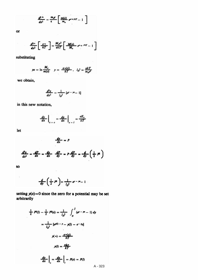
A - 323

A - 324

A - 325
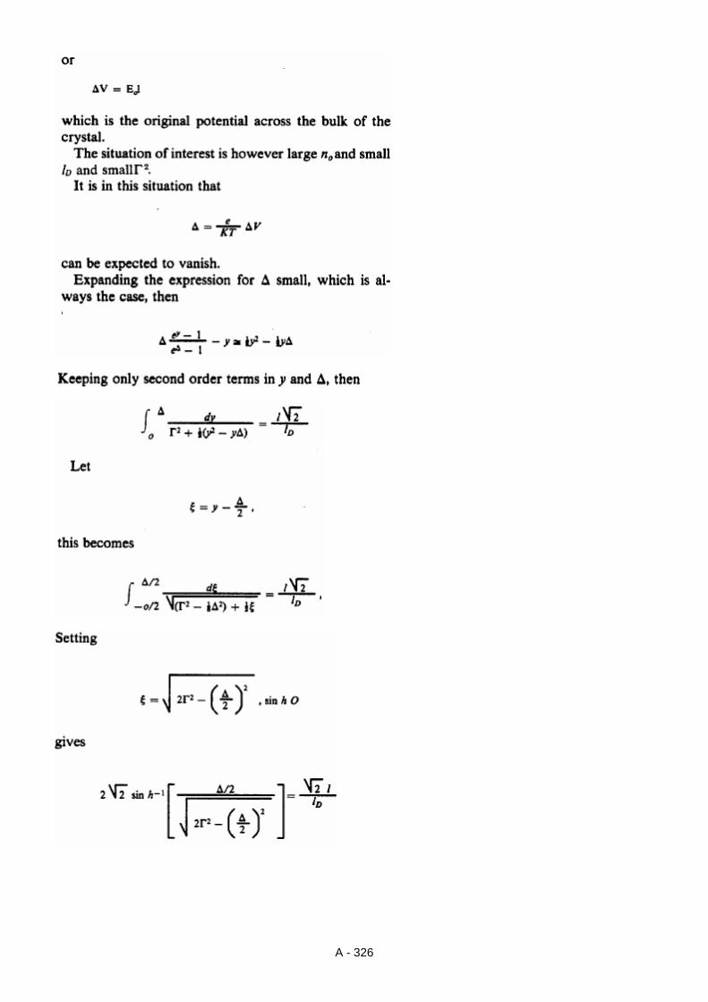
A - 326
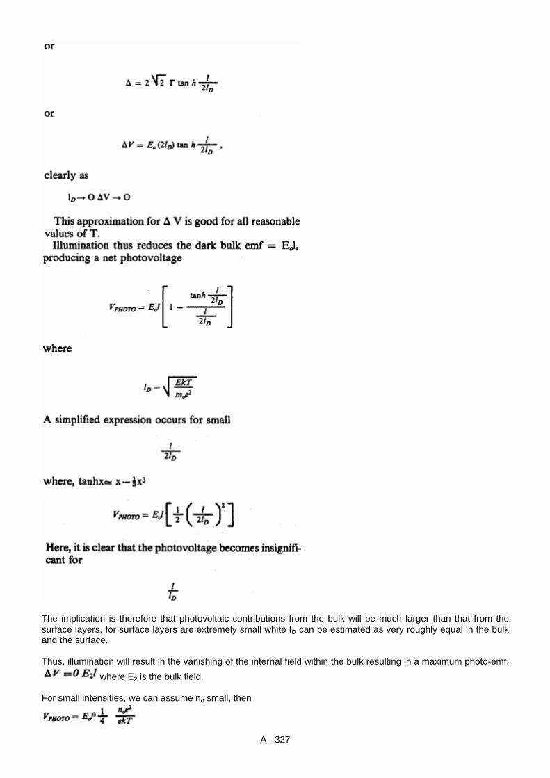
A - 327
The implication is therefore that photovoltaic contributions from the bulk will be much larger than that from the surface layers, for surface layers are extremely small white lD can be estimated as very roughly equal in the bulk and the surface. Thus, illumination will result in the vanishing of the internal field within the bulk resulting in a maximum photo-emf.
where E2 is the bulk field. For small intensities, we can assume no small, then
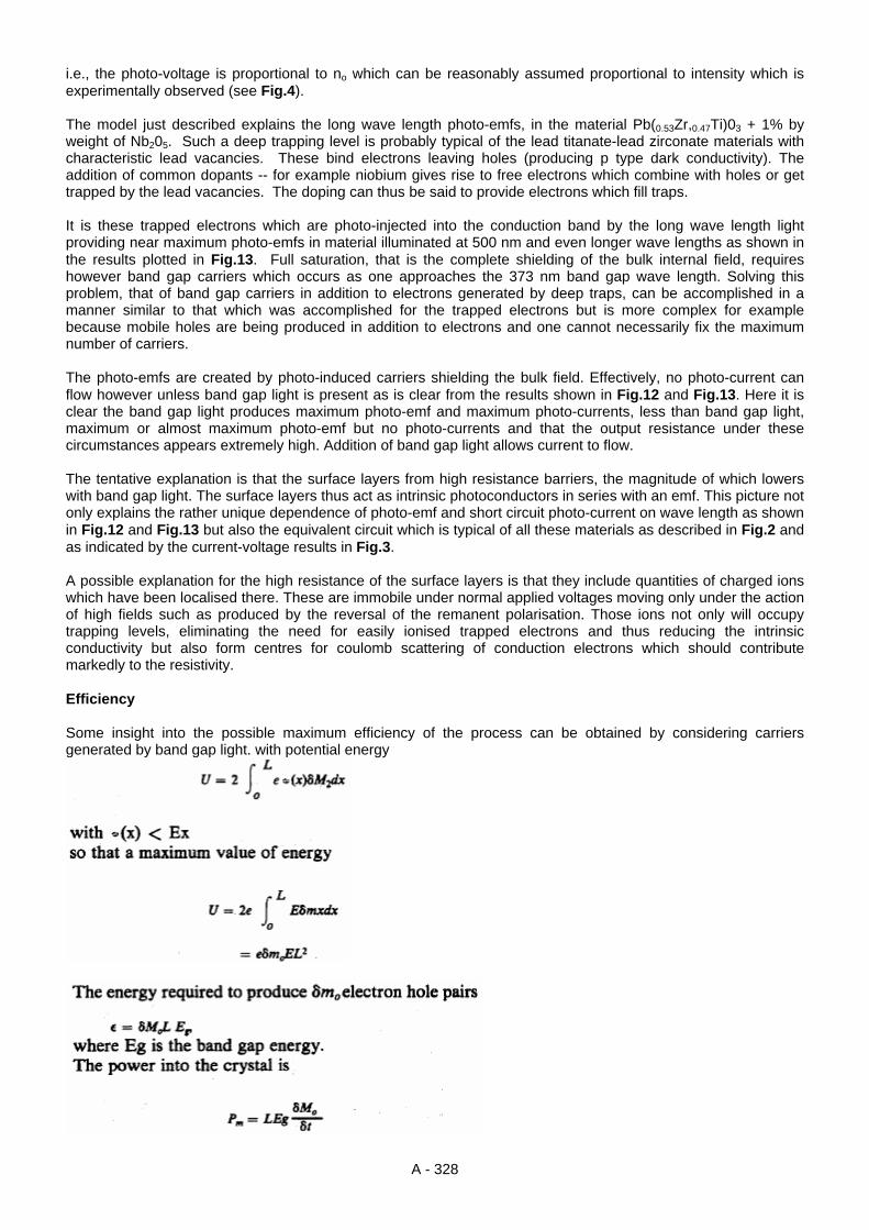
A - 328
i.e., the photo-voltage is proportional to no which can be reasonably assumed proportional to intensity which is experimentally observed (see Fig.4). The model just described explains the long wave length photo-emfs, in the material Pb(0.53Zr,0.47Ti)03 + 1% by weight of Nb205. Such a deep trapping level is probably typical of the lead titanate-lead zirconate materials with characteristic lead vacancies. These bind electrons leaving holes (producing p type dark conductivity). The addition of common dopants -- for example niobium gives rise to free electrons which combine with holes or get trapped by the lead vacancies. The doping can thus be said to provide electrons which fill traps. It is these trapped electrons which are photo-injected into the conduction band by the long wave length light providing near maximum photo-emfs in material illuminated at 500 nm and even longer wave lengths as shown in the results plotted in Fig.13. Full saturation, that is the complete shielding of the bulk internal field, requires however band gap carriers which occurs as one approaches the 373 nm band gap wave length. Solving this problem, that of band gap carriers in addition to electrons generated by deep traps, can be accomplished in a manner similar to that which was accomplished for the trapped electrons but is more complex for example because mobile holes are being produced in addition to electrons and one cannot necessarily fix the maximum number of carriers. The photo-emfs are created by photo-induced carriers shielding the bulk field. Effectively, no photo-current can flow however unless band gap light is present as is clear from the results shown in Fig.12 and Fig.13. Here it is clear the band gap light produces maximum photo-emf and maximum photo-currents, less than band gap light, maximum or almost maximum photo-emf but no photo-currents and that the output resistance under these circumstances appears extremely high. Addition of band gap light allows current to flow. The tentative explanation is that the surface layers from high resistance barriers, the magnitude of which lowers with band gap light. The surface layers thus act as intrinsic photoconductors in series with an emf. This picture not only explains the rather unique dependence of photo-emf and short circuit photo-current on wave length as shown in Fig.12 and Fig.13 but also the equivalent circuit which is typical of all these materials as described in Fig.2 and as indicated by the current-voltage results in Fig.3. A possible explanation for the high resistance of the surface layers is that they include quantities of charged ions which have been localised there. These are immobile under normal applied voltages moving only under the action of high fields such as produced by the reversal of the remanent polarisation. Those ions not only will occupy trapping levels, eliminating the need for easily ionised trapped electrons and thus reducing the intrinsic conductivity but also form centres for coulomb scattering of conduction electrons which should contribute markedly to the resistivity. Efficiency Some insight into the possible maximum efficiency of the process can be obtained by considering carriers generated by band gap light. with potential energy

A - 329
Which compares with an observed band gap efficiency of about 0.06%. The calculation, of course, depends on idealising assumptions, some of which may be practically obtainable. PHOTOVOLTAIC MEMORY DEVICE With the above background and general teachings of the unique discovery of the invention now firmly in mind, numerous and important applications of the properties of the ferroelectric ceramics above-discussed are readily possible as will be evident to those skilled in this art. For example, the device of the instant invention will be shown to exhibit particular utility as a memory apparatus, thus making use of the property of the ferroelectric ceramic defined as remanent polarisation or "memory” as previously explained. With particular reference now to Fig.26 of the application drawings, one such photovoltaic memory apparatus is disclosed, the memory apparatus being optically addressed. In this respect, a substrate or sheet of a ferroelectric ceramic material of the type above-discussed is indicated by reference numeral 10 as being "sandwiched" between at least one pair of electrodes such as electrodes 12 and 14 positioned on opposing sides of the substrate. In the preferred embodiment as shown, an array of electrode pairs, such as pairs 12-14 and 16-18 are disposed on opposing sides of the substrate 10 as to define a matrix configuration. Information is put into the memory and particularly into the region of the substrate 10 lying between electrode pairs by temporarily applying a voltage pulse of a predetermined polarity between the electrode pairs, such pulse being provided by the Write Pulse Generator 20 coupled to the various electrodes and of typical construction. Specifically, if a positive voltage pulse was provided by the Write Pulse Generator 20 between electrode pairs 12-14, with electrode 12 being presumed to be the positive electrode in this example, a remanent ferroelectric polarisation will take place in the region of substrate 10 lying between the crossed electrode pair, this remanent polarisation being in a direction and of a polarity dependent upon the polarity of the write pulse. Similarly, if a negative voltage pulse was applied between electrode 16 on the one hand, and electrode 18 on the other hand, with electrode 16 in this instance being presumed to have the negative polarity, a remanent polarisation within the ferroelectric ceramic 10 will take place in the region disposed between the intersecting or crossed electrodes 16 and 18. In a similar fashion, predetermined remanent polarisation can be produced individually in all of the regions of the ferroelectric ceramic 10 that are disposed between crossed electrode pairs of the matrix array in direct dependence upon the polarity of the write pulse voltage applied, this remanent ferroelectric polarisation constituting stored information in that such polarisation within the ceramic will remain until removed by the application of a write voltage pulse of opposing polarity. In accordance with the teachings of the instant invention, these stored "bits" of information in the form of remanent ferroelectric polarisation within the various regions of the substrate 10 can be extracted or "read" by selectively illuminating the poled regions of the substrate with a beam of light, as preferably can be provided by a laser, for example. Upon illumination, the polarised regions of the ferroelectric ceramic will produce a photovoltaic current and voltage at an associated electrode pair, with the polarity of the photo-current and photo-voltage being
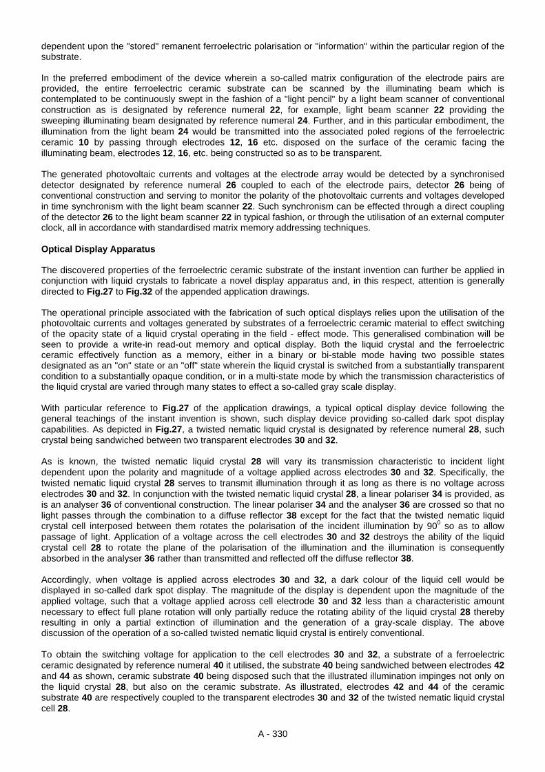
A - 330
dependent upon the "stored" remanent ferroelectric polarisation or "information" within the particular region of the substrate. In the preferred embodiment of the device wherein a so-called matrix configuration of the electrode pairs are provided, the entire ferroelectric ceramic substrate can be scanned by the illuminating beam which is contemplated to be continuously swept in the fashion of a "light pencil" by a light beam scanner of conventional construction as is designated by reference numeral 22, for example, light beam scanner 22 providing the sweeping illuminating beam designated by reference numeral 24. Further, and in this particular embodiment, the illumination from the light beam 24 would be transmitted into the associated poled regions of the ferroelectric ceramic 10 by passing through electrodes 12, 16 etc. disposed on the surface of the ceramic facing the illuminating beam, electrodes 12, 16, etc. being constructed so as to be transparent. The generated photovoltaic currents and voltages at the electrode array would be detected by a synchronised detector designated by reference numeral 26 coupled to each of the electrode pairs, detector 26 being of conventional construction and serving to monitor the polarity of the photovoltaic currents and voltages developed in time synchronism with the light beam scanner 22. Such synchronism can be effected through a direct coupling of the detector 26 to the light beam scanner 22 in typical fashion, or through the utilisation of an external computer clock, all in accordance with standardised matrix memory addressing techniques. Optical Display Apparatus The discovered properties of the ferroelectric ceramic substrate of the instant invention can further be applied in conjunction with liquid crystals to fabricate a novel display apparatus and, in this respect, attention is generally directed to Fig.27 to Fig.32 of the appended application drawings. The operational principle associated with the fabrication of such optical displays relies upon the utilisation of the photovoltaic currents and voltages generated by substrates of a ferroelectric ceramic material to effect switching of the opacity state of a liquid crystal operating in the field - effect mode. This generalised combination will be seen to provide a write-in read-out memory and optical display. Both the liquid crystal and the ferroelectric ceramic effectively function as a memory, either in a binary or bi-stable mode having two possible states designated as an "on" state or an "off" state wherein the liquid crystal is switched from a substantially transparent condition to a substantially opaque condition, or in a multi-state mode by which the transmission characteristics of the liquid crystal are varied through many states to effect a so-called gray scale display. With particular reference to Fig.27 of the application drawings, a typical optical display device following the general teachings of the instant invention is shown, such display device providing so-called dark spot display capabilities. As depicted in Fig.27, a twisted nematic liquid crystal is designated by reference numeral 28, such crystal being sandwiched between two transparent electrodes 30 and 32. As is known, the twisted nematic liquid crystal 28 will vary its transmission characteristic to incident light dependent upon the polarity and magnitude of a voltage applied across electrodes 30 and 32. Specifically, the twisted nematic liquid crystal 28 serves to transmit illumination through it as long as there is no voltage across electrodes 30 and 32. In conjunction with the twisted nematic liquid crystal 28, a linear polariser 34 is provided, as is an analyser 36 of conventional construction. The linear polariser 34 and the analyser 36 are crossed so that no light passes through the combination to a diffuse reflector 38 except for the fact that the twisted nematic liquid crystal cell interposed between them rotates the polarisation of the incident illumination by 900 so as to allow passage of light. Application of a voltage across the cell electrodes 30 and 32 destroys the ability of the liquid crystal cell 28 to rotate the plane of the polarisation of the illumination and the illumination is consequently absorbed in the analyser 36 rather than transmitted and reflected off the diffuse reflector 38. Accordingly, when voltage is applied across electrodes 30 and 32, a dark colour of the liquid cell would be displayed in so-called dark spot display. The magnitude of the display is dependent upon the magnitude of the applied voltage, such that a voltage applied across cell electrode 30 and 32 less than a characteristic amount necessary to effect full plane rotation will only partially reduce the rotating ability of the liquid crystal 28 thereby resulting in only a partial extinction of illumination and the generation of a gray-scale display. The above discussion of the operation of a so-called twisted nematic liquid crystal is entirely conventional. To obtain the switching voltage for application to the cell electrodes 30 and 32, a substrate of a ferroelectric ceramic designated by reference numeral 40 it utilised, the substrate 40 being sandwiched between electrodes 42 and 44 as shown, ceramic substrate 40 being disposed such that the illustrated illumination impinges not only on the liquid crystal 28, but also on the ceramic substrate. As illustrated, electrodes 42 and 44 of the ceramic substrate 40 are respectively coupled to the transparent electrodes 30 and 32 of the twisted nematic liquid crystal cell 28.
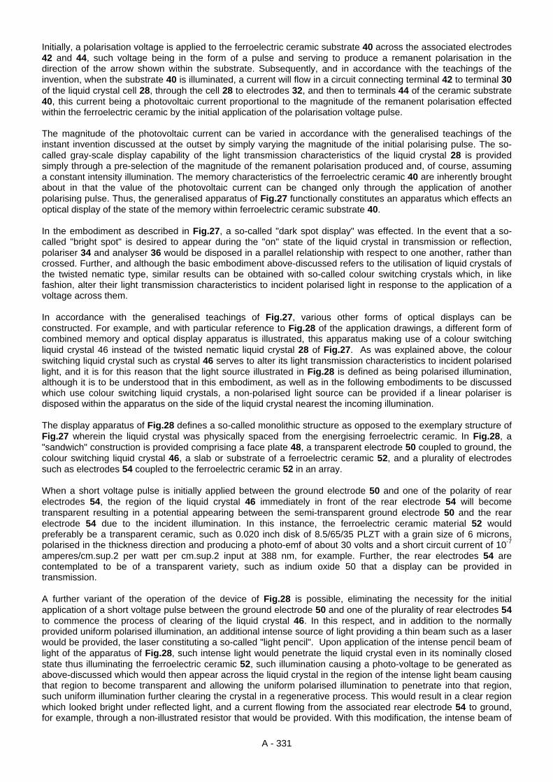
A - 331
Initially, a polarisation voltage is applied to the ferroelectric ceramic substrate 40 across the associated electrodes 42 and 44, such voltage being in the form of a pulse and serving to produce a remanent polarisation in the direction of the arrow shown within the substrate. Subsequently, and in accordance with the teachings of the invention, when the substrate 40 is illuminated, a current will flow in a circuit connecting terminal 42 to terminal 30 of the liquid crystal cell 28, through the cell 28 to electrodes 32, and then to terminals 44 of the ceramic substrate 40, this current being a photovoltaic current proportional to the magnitude of the remanent polarisation effected within the ferroelectric ceramic by the initial application of the polarisation voltage pulse. The magnitude of the photovoltaic current can be varied in accordance with the generalised teachings of the instant invention discussed at the outset by simply varying the magnitude of the initial polarising pulse. The so-called gray-scale display capability of the light transmission characteristics of the liquid crystal 28 is provided simply through a pre-selection of the magnitude of the remanent polarisation produced and, of course, assuming a constant intensity illumination. The memory characteristics of the ferroelectric ceramic 40 are inherently brought about in that the value of the photovoltaic current can be changed only through the application of another polarising pulse. Thus, the generalised apparatus of Fig.27 functionally constitutes an apparatus which effects an optical display of the state of the memory within ferroelectric ceramic substrate 40. In the embodiment as described in Fig.27, a so-called "dark spot display" was effected. In the event that a so-called "bright spot" is desired to appear during the "on" state of the liquid crystal in transmission or reflection, polariser 34 and analyser 36 would be disposed in a parallel relationship with respect to one another, rather than crossed. Further, and although the basic embodiment above-discussed refers to the utilisation of liquid crystals of the twisted nematic type, similar results can be obtained with so-called colour switching crystals which, in like fashion, alter their light transmission characteristics to incident polarised light in response to the application of a voltage across them. In accordance with the generalised teachings of Fig.27, various other forms of optical displays can be constructed. For example, and with particular reference to Fig.28 of the application drawings, a different form of combined memory and optical display apparatus is illustrated, this apparatus making use of a colour switching liquid crystal 46 instead of the twisted nematic liquid crystal 28 of Fig.27. As was explained above, the colour switching liquid crystal such as crystal 46 serves to alter its light transmission characteristics to incident polarised light, and it is for this reason that the light source illustrated in Fig.28 is defined as being polarised illumination, although it is to be understood that in this embodiment, as well as in the following embodiments to be discussed which use colour switching liquid crystals, a non-polarised light source can be provided if a linear polariser is disposed within the apparatus on the side of the liquid crystal nearest the incoming illumination. The display apparatus of Fig.28 defines a so-called monolithic structure as opposed to the exemplary structure of Fig.27 wherein the liquid crystal was physically spaced from the energising ferroelectric ceramic. In Fig.28, a "sandwich" construction is provided comprising a face plate 48, a transparent electrode 50 coupled to ground, the colour switching liquid crystal 46, a slab or substrate of a ferroelectric ceramic 52, and a plurality of electrodes such as electrodes 54 coupled to the ferroelectric ceramic 52 in an array. When a short voltage pulse is initially applied between the ground electrode 50 and one of the polarity of rear electrodes 54, the region of the liquid crystal 46 immediately in front of the rear electrode 54 will become transparent resulting in a potential appearing between the semi-transparent ground electrode 50 and the rear electrode 54 due to the incident illumination. In this instance, the ferroelectric ceramic material 52 would preferably be a transparent ceramic, such as 0.020 inch disk of 8.5/65/35 PLZT with a grain size of 6 microns, polarised in the thickness direction and producing a photo-emf of about 30 volts and a short circuit current of 10-7 amperes/cm.sup.2 per watt per cm.sup.2 input at 388 nm, for example. Further, the rear electrodes 54 are contemplated to be of a transparent variety, such as indium oxide 50 that a display can be provided in transmission. A further variant of the operation of the device of Fig.28 is possible, eliminating the necessity for the initial application of a short voltage pulse between the ground electrode 50 and one of the plurality of rear electrodes 54 to commence the process of clearing of the liquid crystal 46. In this respect, and in addition to the normally provided uniform polarised illumination, an additional intense source of light providing a thin beam such as a laser would be provided, the laser constituting a so-called "light pencil". Upon application of the intense pencil beam of light of the apparatus of Fig.28, such intense light would penetrate the liquid crystal even in its nominally closed state thus illuminating the ferroelectric ceramic 52, such illumination causing a photo-voltage to be generated as above-discussed which would then appear across the liquid crystal in the region of the intense light beam causing that region to become transparent and allowing the uniform polarised illumination to penetrate into that region, such uniform illumination further clearing the crystal in a regenerative process. This would result in a clear region which looked bright under reflected light, and a current flowing from the associated rear electrode 54 to ground, for example, through a non-illustrated resistor that would be provided. With this modification, the intense beam of
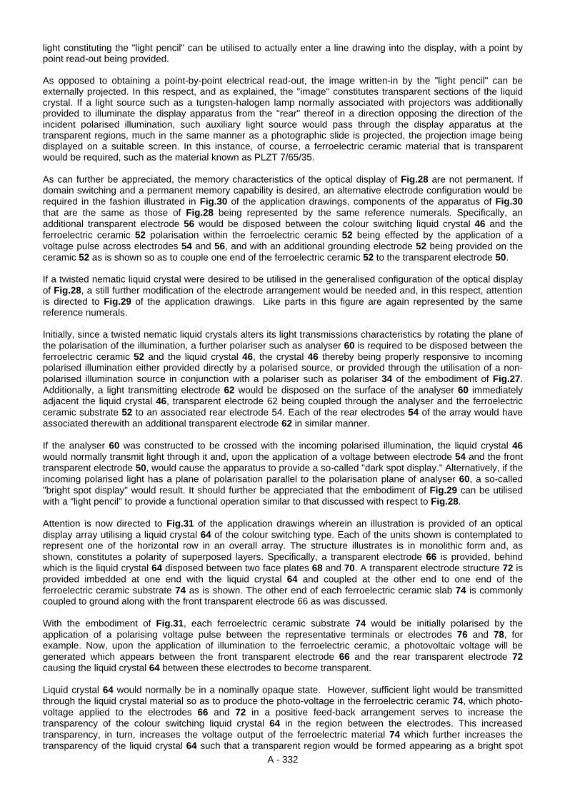
A - 332
light constituting the "light pencil" can be utilised to actually enter a line drawing into the display, with a point by point read-out being provided. As opposed to obtaining a point-by-point electrical read-out, the image written-in by the "light pencil" can be externally projected. In this respect, and as explained, the "image" constitutes transparent sections of the liquid crystal. If a light source such as a tungsten-halogen lamp normally associated with projectors was additionally provided to illuminate the display apparatus from the "rear" thereof in a direction opposing the direction of the incident polarised illumination, such auxiliary light source would pass through the display apparatus at the transparent regions, much in the same manner as a photographic slide is projected, the projection image being displayed on a suitable screen. In this instance, of course, a ferroelectric ceramic material that is transparent would be required, such as the material known as PLZT 7/65/35. As can further be appreciated, the memory characteristics of the optical display of Fig.28 are not permanent. If domain switching and a permanent memory capability is desired, an alternative electrode configuration would be required in the fashion illustrated in Fig.30 of the application drawings, components of the apparatus of Fig.30 that are the same as those of Fig.28 being represented by the same reference numerals. Specifically, an additional transparent electrode 56 would be disposed between the colour switching liquid crystal 46 and the ferroelectric ceramic 52 polarisation within the ferroelectric ceramic 52 being effected by the application of a voltage pulse across electrodes 54 and 56, and with an additional grounding electrode 52 being provided on the ceramic 52 as is shown so as to couple one end of the ferroelectric ceramic 52 to the transparent electrode 50. If a twisted nematic liquid crystal were desired to be utilised in the generalised configuration of the optical display of Fig.28, a still further modification of the electrode arrangement would be needed and, in this respect, attention is directed to Fig.29 of the application drawings. Like parts in this figure are again represented by the same reference numerals. Initially, since a twisted nematic liquid crystals alters its light transmissions characteristics by rotating the plane of the polarisation of the illumination, a further polariser such as analyser 60 is required to be disposed between the ferroelectric ceramic 52 and the liquid crystal 46, the crystal 46 thereby being properly responsive to incoming polarised illumination either provided directly by a polarised source, or provided through the utilisation of a non-polarised illumination source in conjunction with a polariser such as polariser 34 of the embodiment of Fig.27. Additionally, a light transmitting electrode 62 would be disposed on the surface of the analyser 60 immediately adjacent the liquid crystal 46, transparent electrode 62 being coupled through the analyser and the ferroelectric ceramic substrate 52 to an associated rear electrode 54. Each of the rear electrodes 54 of the array would have associated therewith an additional transparent electrode 62 in similar manner. If the analyser 60 was constructed to be crossed with the incoming polarised illumination, the liquid crystal 46 would normally transmit light through it and, upon the application of a voltage between electrode 54 and the front transparent electrode 50, would cause the apparatus to provide a so-called "dark spot display." Alternatively, if the incoming polarised light has a plane of polarisation parallel to the polarisation plane of analyser 60, a so-called "bright spot display" would result. It should further be appreciated that the embodiment of Fig.29 can be utilised with a "light pencil" to provide a functional operation similar to that discussed with respect to Fig.28. Attention is now directed to Fig.31 of the application drawings wherein an illustration is provided of an optical display array utilising a liquid crystal 64 of the colour switching type. Each of the units shown is contemplated to represent one of the horizontal row in an overall array. The structure illustrates is in monolithic form and, as shown, constitutes a polarity of superposed layers. Specifically, a transparent electrode 66 is provided, behind which is the liquid crystal 64 disposed between two face plates 68 and 70. A transparent electrode structure 72 is provided imbedded at one end with the liquid crystal 64 and coupled at the other end to one end of the ferroelectric ceramic substrate 74 as is shown. The other end of each ferroelectric ceramic slab 74 is commonly coupled to ground along with the front transparent electrode 66 as was discussed. With the embodiment of Fig.31, each ferroelectric ceramic substrate 74 would be initially polarised by the application of a polarising voltage pulse between the representative terminals or electrodes 76 and 78, for example. Now, upon the application of illumination to the ferroelectric ceramic, a photovoltaic voltage will be generated which appears between the front transparent electrode 66 and the rear transparent electrode 72 causing the liquid crystal 64 between these electrodes to become transparent. Liquid crystal 64 would normally be in a nominally opaque state. However, sufficient light would be transmitted through the liquid crystal material so as to produce the photo-voltage in the ferroelectric ceramic 74, which photo-voltage applied to the electrodes 66 and 72 in a positive feed-back arrangement serves to increase the transparency of the colour switching liquid crystal 64 in the region between the electrodes. This increased transparency, in turn, increases the voltage output of the ferroelectric material 74 which further increases the transparency of the liquid crystal 64 such that a transparent region would be formed appearing as a bright spot
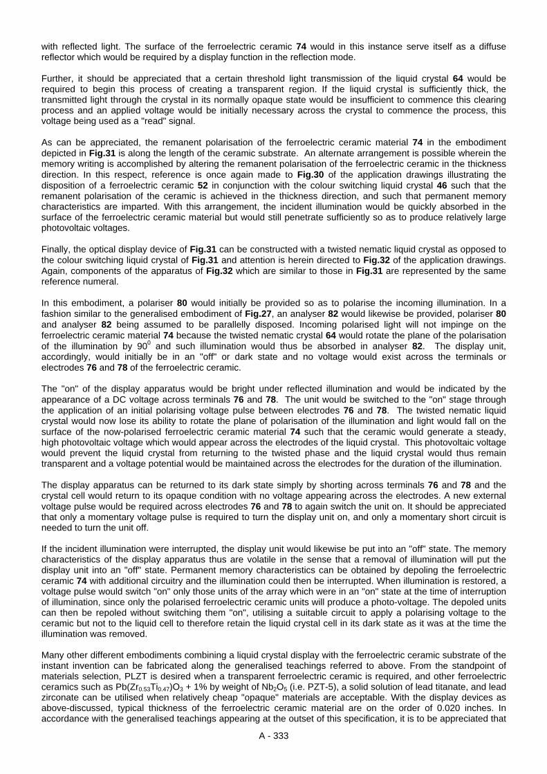
A - 333
with reflected light. The surface of the ferroelectric ceramic 74 would in this instance serve itself as a diffuse reflector which would be required by a display function in the reflection mode. Further, it should be appreciated that a certain threshold light transmission of the liquid crystal 64 would be required to begin this process of creating a transparent region. If the liquid crystal is sufficiently thick, the transmitted light through the crystal in its normally opaque state would be insufficient to commence this clearing process and an applied voltage would be initially necessary across the crystal to commence the process, this voltage being used as a "read" signal. As can be appreciated, the remanent polarisation of the ferroelectric ceramic material 74 in the embodiment depicted in Fig.31 is along the length of the ceramic substrate. An alternate arrangement is possible wherein the memory writing is accomplished by altering the remanent polarisation of the ferroelectric ceramic in the thickness direction. In this respect, reference is once again made to Fig.30 of the application drawings illustrating the disposition of a ferroelectric ceramic 52 in conjunction with the colour switching liquid crystal 46 such that the remanent polarisation of the ceramic is achieved in the thickness direction, and such that permanent memory characteristics are imparted. With this arrangement, the incident illumination would be quickly absorbed in the surface of the ferroelectric ceramic material but would still penetrate sufficiently so as to produce relatively large photovoltaic voltages. Finally, the optical display device of Fig.31 can be constructed with a twisted nematic liquid crystal as opposed to the colour switching liquid crystal of Fig.31 and attention is herein directed to Fig.32 of the application drawings. Again, components of the apparatus of Fig.32 which are similar to those in Fig.31 are represented by the same reference numeral. In this embodiment, a polariser 80 would initially be provided so as to polarise the incoming illumination. In a fashion similar to the generalised embodiment of Fig.27, an analyser 82 would likewise be provided, polariser 80 and analyser 82 being assumed to be parallelly disposed. Incoming polarised light will not impinge on the ferroelectric ceramic material 74 because the twisted nematic crystal 64 would rotate the plane of the polarisation of the illumination by 900 and such illumination would thus be absorbed in analyser 82. The display unit, accordingly, would initially be in an "off" or dark state and no voltage would exist across the terminals or electrodes 76 and 78 of the ferroelectric ceramic. The "on" of the display apparatus would be bright under reflected illumination and would be indicated by the appearance of a DC voltage across terminals 76 and 78. The unit would be switched to the "on" stage through the application of an initial polarising voltage pulse between electrodes 76 and 78. The twisted nematic liquid crystal would now lose its ability to rotate the plane of polarisation of the illumination and light would fall on the surface of the now-polarised ferroelectric ceramic material 74 such that the ceramic would generate a steady, high photovoltaic voltage which would appear across the electrodes of the liquid crystal. This photovoltaic voltage would prevent the liquid crystal from returning to the twisted phase and the liquid crystal would thus remain transparent and a voltage potential would be maintained across the electrodes for the duration of the illumination. The display apparatus can be returned to its dark state simply by shorting across terminals 76 and 78 and the crystal cell would return to its opaque condition with no voltage appearing across the electrodes. A new external voltage pulse would be required across electrodes 76 and 78 to again switch the unit on. It should be appreciated that only a momentary voltage pulse is required to turn the display unit on, and only a momentary short circuit is needed to turn the unit off. If the incident illumination were interrupted, the display unit would likewise be put into an "off" state. The memory characteristics of the display apparatus thus are volatile in the sense that a removal of illumination will put the display unit into an "off" state. Permanent memory characteristics can be obtained by depoling the ferroelectric ceramic 74 with additional circuitry and the illumination could then be interrupted. When illumination is restored, a voltage pulse would switch "on" only those units of the array which were in an "on" state at the time of interruption of illumination, since only the polarised ferroelectric ceramic units will produce a photo-voltage. The depoled units can then be repoled without switching them "on", utilising a suitable circuit to apply a polarising voltage to the ceramic but not to the liquid cell to therefore retain the liquid crystal cell in its dark state as it was at the time the illumination was removed. Many other different embodiments combining a liquid crystal display with the ferroelectric ceramic substrate of the instant invention can be fabricated along the generalised teachings referred to above. From the standpoint of materials selection, PLZT is desired when a transparent ferroelectric ceramic is required, and other ferroelectric ceramics such as Pb(Zr0.53Ti0.47)O3 + 1% by weight of Nb2O5 (i.e. PZT-5), a solid solution of lead titanate, and lead zirconate can be utilised when relatively cheap "opaque" materials are acceptable. With the display devices as above-discussed, typical thickness of the ferroelectric ceramic material are on the order of 0.020 inches. In accordance with the generalised teachings appearing at the outset of this specification, it is to be appreciated that
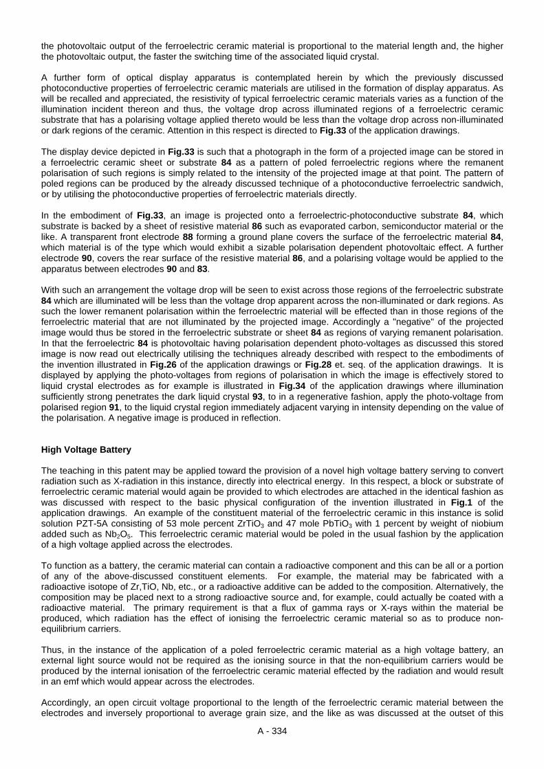
A - 334
the photovoltaic output of the ferroelectric ceramic material is proportional to the material length and, the higher the photovoltaic output, the faster the switching time of the associated liquid crystal. A further form of optical display apparatus is contemplated herein by which the previously discussed photoconductive properties of ferroelectric ceramic materials are utilised in the formation of display apparatus. As will be recalled and appreciated, the resistivity of typical ferroelectric ceramic materials varies as a function of the illumination incident thereon and thus, the voltage drop across illuminated regions of a ferroelectric ceramic substrate that has a polarising voltage applied thereto would be less than the voltage drop across non-illuminated or dark regions of the ceramic. Attention in this respect is directed to Fig.33 of the application drawings. The display device depicted in Fig.33 is such that a photograph in the form of a projected image can be stored in a ferroelectric ceramic sheet or substrate 84 as a pattern of poled ferroelectric regions where the remanent polarisation of such regions is simply related to the intensity of the projected image at that point. The pattern of poled regions can be produced by the already discussed technique of a photoconductive ferroelectric sandwich, or by utilising the photoconductive properties of ferroelectric materials directly. In the embodiment of Fig.33, an image is projected onto a ferroelectric-photoconductive substrate 84, which substrate is backed by a sheet of resistive material 86 such as evaporated carbon, semiconductor material or the like. A transparent front electrode 88 forming a ground plane covers the surface of the ferroelectric material 84, which material is of the type which would exhibit a sizable polarisation dependent photovoltaic effect. A further electrode 90, covers the rear surface of the resistive material 86, and a polarising voltage would be applied to the apparatus between electrodes 90 and 83. With such an arrangement the voltage drop will be seen to exist across those regions of the ferroelectric substrate 84 which are illuminated will be less than the voltage drop apparent across the non-illuminated or dark regions. As such the lower remanent polarisation within the ferroelectric material will be effected than in those regions of the ferroelectric material that are not illuminated by the projected image. Accordingly a "negative" of the projected image would thus be stored in the ferroelectric substrate or sheet 84 as regions of varying remanent polarisation. In that the ferroelectric 84 is photovoltaic having polarisation dependent photo-voltages as discussed this stored image is now read out electrically utilising the techniques already described with respect to the embodiments of the invention illustrated in Fig.26 of the application drawings or Fig.28 et. seq. of the application drawings. It is displayed by applying the photo-voltages from regions of polarisation in which the image is effectively stored to liquid crystal electrodes as for example is illustrated in Fig.34 of the application drawings where illumination sufficiently strong penetrates the dark liquid crystal 93, to in a regenerative fashion, apply the photo-voltage from polarised region 91, to the liquid crystal region immediately adjacent varying in intensity depending on the value of the polarisation. A negative image is produced in reflection. High Voltage Battery The teaching in this patent may be applied toward the provision of a novel high voltage battery serving to convert radiation such as X-radiation in this instance, directly into electrical energy. In this respect, a block or substrate of ferroelectric ceramic material would again be provided to which electrodes are attached in the identical fashion as was discussed with respect to the basic physical configuration of the invention illustrated in Fig.1 of the application drawings. An example of the constituent material of the ferroelectric ceramic in this instance is solid solution PZT-5A consisting of 53 mole percent ZrTiO3 and 47 mole PbTiO3 with 1 percent by weight of niobium added such as Nb2O5. This ferroelectric ceramic material would be poled in the usual fashion by the application of a high voltage applied across the electrodes. To function as a battery, the ceramic material can contain a radioactive component and this can be all or a portion of any of the above-discussed constituent elements. For example, the material may be fabricated with a radioactive isotope of Zr,TiO, Nb, etc., or a radioactive additive can be added to the composition. Alternatively, the composition may be placed next to a strong radioactive source and, for example, could actually be coated with a radioactive material. The primary requirement is that a flux of gamma rays or X-rays within the material be produced, which radiation has the effect of ionising the ferroelectric ceramic material so as to produce non-equilibrium carriers. Thus, in the instance of the application of a poled ferroelectric ceramic material as a high voltage battery, an external light source would not be required as the ionising source in that the non-equilibrium carriers would be produced by the internal ionisation of the ferroelectric ceramic material effected by the radiation and would result in an emf which would appear across the electrodes. Accordingly, an open circuit voltage proportional to the length of the ferroelectric ceramic material between the electrodes and inversely proportional to average grain size, and the like as was discussed at the outset of this
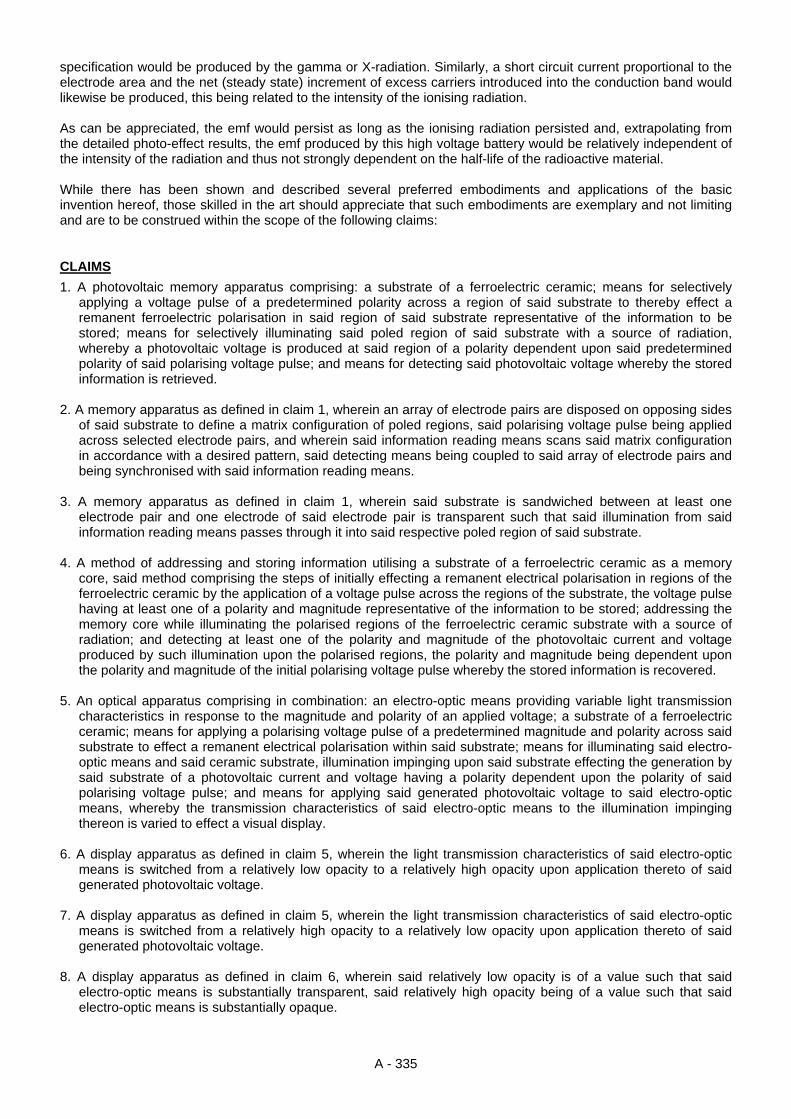
A - 335
specification would be produced by the gamma or X-radiation. Similarly, a short circuit current proportional to the electrode area and the net (steady state) increment of excess carriers introduced into the conduction band would likewise be produced, this being related to the intensity of the ionising radiation. As can be appreciated, the emf would persist as long as the ionising radiation persisted and, extrapolating from the detailed photo-effect results, the emf produced by this high voltage battery would be relatively independent of the intensity of the radiation and thus not strongly dependent on the half-life of the radioactive material. While there has been shown and described several preferred embodiments and applications of the basic invention hereof, those skilled in the art should appreciate that such embodiments are exemplary and not limiting and are to be construed within the scope of the following claims: CLAIMS 1. A photovoltaic memory apparatus comprising: a substrate of a ferroelectric ceramic; means for selectively
applying a voltage pulse of a predetermined polarity across a region of said substrate to thereby effect a remanent ferroelectric polarisation in said region of said substrate representative of the information to be stored; means for selectively illuminating said poled region of said substrate with a source of radiation, whereby a photovoltaic voltage is produced at said region of a polarity dependent upon said predetermined polarity of said polarising voltage pulse; and means for detecting said photovoltaic voltage whereby the stored information is retrieved.
2. A memory apparatus as defined in claim 1, wherein an array of electrode pairs are disposed on opposing sides
of said substrate to define a matrix configuration of poled regions, said polarising voltage pulse being applied across selected electrode pairs, and wherein said information reading means scans said matrix configuration in accordance with a desired pattern, said detecting means being coupled to said array of electrode pairs and being synchronised with said information reading means.
3. A memory apparatus as defined in claim 1, wherein said substrate is sandwiched between at least one
electrode pair and one electrode of said electrode pair is transparent such that said illumination from said information reading means passes through it into said respective poled region of said substrate.
4. A method of addressing and storing information utilising a substrate of a ferroelectric ceramic as a memory
core, said method comprising the steps of initially effecting a remanent electrical polarisation in regions of the ferroelectric ceramic by the application of a voltage pulse across the regions of the substrate, the voltage pulse having at least one of a polarity and magnitude representative of the information to be stored; addressing the memory core while illuminating the polarised regions of the ferroelectric ceramic substrate with a source of radiation; and detecting at least one of the polarity and magnitude of the photovoltaic current and voltage produced by such illumination upon the polarised regions, the polarity and magnitude being dependent upon the polarity and magnitude of the initial polarising voltage pulse whereby the stored information is recovered.
5. An optical apparatus comprising in combination: an electro-optic means providing variable light transmission
characteristics in response to the magnitude and polarity of an applied voltage; a substrate of a ferroelectric ceramic; means for applying a polarising voltage pulse of a predetermined magnitude and polarity across said substrate to effect a remanent electrical polarisation within said substrate; means for illuminating said electro-optic means and said ceramic substrate, illumination impinging upon said substrate effecting the generation by said substrate of a photovoltaic current and voltage having a polarity dependent upon the polarity of said polarising voltage pulse; and means for applying said generated photovoltaic voltage to said electro-optic means, whereby the transmission characteristics of said electro-optic means to the illumination impinging thereon is varied to effect a visual display.
6. A display apparatus as defined in claim 5, wherein the light transmission characteristics of said electro-optic
means is switched from a relatively low opacity to a relatively high opacity upon application thereto of said generated photovoltaic voltage.
7. A display apparatus as defined in claim 5, wherein the light transmission characteristics of said electro-optic
means is switched from a relatively high opacity to a relatively low opacity upon application thereto of said generated photovoltaic voltage.
8. A display apparatus as defined in claim 6, wherein said relatively low opacity is of a value such that said
electro-optic means is substantially transparent, said relatively high opacity being of a value such that said electro-optic means is substantially opaque.

A - 336
9. A display apparatus as defined in claim 7, wherein said relatively low opacity is of a value such that said electro-optic means is substantially transparent, said relatively high opacity being of a value such that said electro-optic means is substantially opaque.
10. A display apparatus as defined in claim 5, wherein the magnitude of said polarising voltage is selected such
that the light transmission characteristics of said electro-optic means is switched between varying opacities to define a gray scale.
11. A display apparatus as defined in claim 33, wherein said electro-optic means is a liquid crystal of the twisted
nematic type. 12. A display apparatus as defined in claim 5, wherein said electro-optic means is a liquid crystal of the colour
switching type. 13. A display apparatus as defined in claim 11, wherein said liquid crystal is sandwiched between a light polariser
and a light analyser. 14. A display apparatus as defined in claim 5, wherein said electro-optic means and said ferroelectric ceramic
substrate are disposed in superposition to define a monolithic structure. 15. A display apparatus as defined in claim 14, wherein said electro-optic means is a colour switching liquid
crystal disposed in superposition with said ceramic substrate to define a monolithic structure, and wherein said means for applying a polarising voltage to said substrate and said means for applying said photovoltaic voltage to said liquid crystal comprises a plurality of electrodes disposed on opposite faces of said structure with said structure being sandwiched between them, at least one electrode pair being in contact with said liquid crystal and with said ceramic substrate, respectively; said electrode of said pair which is in contact with said liquid crystal being transparent.
16. A display apparatus as defined in claim 14, wherein said monolithic structure constitutes a plurality of stacked
superposed layers comprising a first transparent electrode, an electro-optic means, a second transparent electrode, said substrate of a ferroelectric ceramic, and a third electrode, said third electrode being coupled to said first electrode, said means for applying said polarising voltage being defined by said second and third electrodes, said means for applying said generated photovoltaic voltage being defined by said first and second electrodes, and wherein said means for illuminating said electro-optic means and said substrate comprises a light beam directed to impinge upon said first transparent electrode.
17. A display apparatus as defined in claim 16, wherein said electro-optic means is a liquid crystal of the colour
switching type. 18. A display apparatus as defined in claim 16, wherein said plurality of stacked layers further includes a polariser
disposed over said first transparent electrode, and an analyser disposed between said second transparent electrode and said ceramic substrate, said electro-optic means being a liquid crystal of the twisted nematic type.
19. A display apparatus as defined in claim 16, wherein said illumination means comprises a source of polarised
light, said plurality of stacked layers including an analyser disposed between said second transparent electrode and said ceramic substrate, said electro-optic means being a liquid crystal of the twisted nematic type.
20. A display apparatus as defined in claim 19, wherein said analyser is disposed in a direction parallel to the
plane of polarisation of the incident illumination. 21. A display apparatus as defined in claim 19, wherein said analyser is disposed so as to be crossed with
respect to the plane of polarisation of the incident illumination. 22. A method of electrically storing optical information comprising the steps of: projecting an image constituting
the optical information onto a sandwich of a ferroelectric ceramic backed by a layer of resistive material to form an illumination pattern thereon; applying a voltage pulse across the sandwich whereby varying remanent polarisations within the ferroelectric ceramic are produced in dependence upon the illumination pattern.
23. The method of claim 22, further including the step of reading out the remanent polarisations to thereby extract
the stored optical information.

A - 337
24. A display apparatus as defined in claim 5, wherein said variation of the transmission characteristics of the electro-optic means ensures that illumination continues to impinge upon said substrate to latch said electro-optical means and maintain said transmission variation thereof.
25. A method of electrically storing optical information comprising the steps of: projecting an image constituting
the optical information onto a ferroelectric ceramic layer to form an illumination pattern thereon and thereby alter the resistivity of the ceramic layer in accordance with said pattern; applying a voltage pulse across the ceramic whereby varying remanent polarisations within the ferroelectric ceramic are produced in dependence upon the illumination pattern.

A - 338
CHARLES FLYNN: MAGNETIC FRAME
Patent US 6,246,561 12th June 2001 Inventor: Charles J. Flynn
METHODS FOR CONTROLLING THE PATH OF MAGNETIC FLUX FROM A PERMANENT MAGNET AND DEVICES INCORPORATING THE SAME
This patent covers a device which is claimed to have a greater output power than the input power required to run it. ABSTRACT A permanent magnet device includes a permanent magnet having north and south pole faces with a first pole piece positioned adjacent one pole face thereof and a second pole piece positioned adjacent the other pole face thereof so as to create at least two potential magnetic flux paths. A first control coil is positioned along one flux path and a second control coil is positioned along the other flux path, each coil being connected to a control circuit for controlling the energisation thereof. The control coils may be energised in a variety of ways to achieved desirable motive and static devices, including linear reciprocating devices, linear motion devices, rotary motion devices and power conversion. DESCRIPTION FIELD OF THE INVENTION This invention relates generally to permanent magnet devices and more particularly, to a permanent magnet control component in which the flow of flux from a permanent magnet is controlled between two or more flux paths by utilising timed delivery of electrical signals through one or more coils placed along at least one of the flux paths. Such permanent magnet control components may take on a variety of configurations facilitating use of such components in a variety of applications including applications involving the production of reciprocating, linear, and rotary motion and power conversion. Several novel permanent magnet rotary motion devices of motor constructions which operate by controlling the path of magnetic flux from one or more permanent magnets are described, such permanent magnet rotary motor constructions having increased efficiency and more desirable torque characteristics as compared to many currently used motors. BACKGROUND OF THE INVENTION Magnetic force of attraction is commonly used in a variety of types of permanent magnet devices including both linear and rotary motors. In the field of such permanent magnet devices there is a continuous pursuit of increased efficiency and reduced complexity. Accordingly, an object of the present invention is to provide a permanent magnet control component in which the path of a given level of permanent magnet flux can be controlled by a lesser level of electromagnetic flux. Another object of the present invention is to provide a permanent magnet control component in which substantially all of the flux from a permanent magnet can be switched between at least two different flux paths of the permanent magnet control component so as to enable useful work in the form of linear, reciprocating, and rotary motion. Still another object of the present invention is to provide permanent magnet control components and motor constructions in which flux path control is provided by energising an 10 electromagnet to oppose the magnetic flux of one or more permanent magnets. Another object of the present invention is to provide permanent magnet control components and motor constructions in which flux path control is provided by energising an electromagnet to aid the magnetic flux of one or more permanent magnets. Yet another object of the present invention is to provide permanent magnet motor 15 constructions with improved operating characteristics.

A - 339
SUMMARY OF THE INVENTION These and other objects of the invention are attained by an apparatus which, in one aspect, is a permanent magnet device, comprising a permanent magnet having north and south pole faces, a first pole piece, a second pole piece, a first control coil, a second control coil, and circuit means, the first pole piece positioned adjacent the north pole face of the permanent magnet and including a first path portion, a second path portion and a third portion, the first path portion extending beyond a perimeter of the north pole face and the second path portion extending beyond the perimeter of the north pole face to define first and second flux paths for magnetic flux emanating from the north pole face of the permanent magnet, the first path portion of the first pole piece connected to the second path portion of the first pole piece by the third portion which extends across the north pole face of the permanent magnet, the second pole piece positioned adjacent the south pole face and including a first path portion and a second path portion, the first path portion extending beyond a perimeter of the south pole face and substantially aligned with the first path portion of the first pole piece, the second path portion extending beyond the perimeter of the south pole face and substantially aligned with the second path portion of the first pole piece, the first control coil positioned around the first path portion of the first pole piece, the second control coil positioned around the second path portion of the first pole piece, the circuit means connected to each of the first control coil and the second control coil to alternately energise the first coil and the second coil in a timed sequential manner. Another aspect of the present invention provides a method for controlling the path of magnetic flux from a permanent magnet which involves placing a first pole piece adjacent a first pole face of the permanent magnet so as to have at least first and second path portions extending beyond a perimeter of the first pole face. A second pole piece is placed adjacent a second pole face of the permanent magnet so as to include at least one portion which substantially aligns with the first and second path portions of the first pole piece. A first control coil is placed along and around the first path portion of the first pole piece and a second control coil is placed along and around the second path portion of the first pole piece. The first control coil is repeatedly energised in a permanent magnet magnetic flux opposing manner so as to prevent magnetic flux of the permanent magnet from traversing the first path portion of the first pole piece, and the second control coil is repeatedly energised in a permanent magnet magnetic flux opposing manner so as to prevent magnetic flux of the permanent magnet from traversing the second path portion of the first pole piece. Yet another aspect of the present invention provides a method for controlling the path of magnetic flux from a permanent magnet by placing a first pole piece adjacent a first pole face of the permanent magnet so as to have at least first and second path portions extending beyond a perimeter of the first pole face. A second pole piece is placed adjacent a second pole face of the permanent magnet so as to include at least one portion which substantially aligns with the first and second path portions of the first pole piece. A first control coil is placed along and around the first path portion of the first pole piece, and a second control coil is placed along and around the second path portion of the first pole piece. The following steps are alternately performed in a repeated manner: (i) energising the first control coil in a permanent magnet magnetic flux aiding manner so as to couple with substantially all magnetic flux of the permanent magnet such that substantially no magnetic flux of the permanent magnet traverses the second path portion of the first pole piece when the first control coil is so energised; and (ii) energising the second control coil in a permanent magnet magnetic flux opposing manner so as to couple with substantially all magnetic flux of the permanent magnet such that substantially no magnetic flux of the permanent magnet traverses the first path portion of the first pole piece when the second control coil is so energised. A further aspect of the present invention provides method for controlling the path of magnetic flux from a permanent magnet by placing a first pole piece adjacent a first pole face of the permanent magnet so as to have at least first and second path portions extending beyond a perimeter of the first pole face, and placing a second pole piece adjacent a second pole face of the permanent magnet so as to include at least one portion which substantially aligns with the first and second path portions of the first pole piece. A first control coil is placed along and around the first path portion of the first pole piece, and a second control coil is placed along and around the second path portion of the first pole piece. The following steps are alternately performed in a repeated manner: (i) energising the first control coil in a permanent magnet magnetic flux aiding manner so as to couple with substantially all magnetic flux of the permanent magnet such that substantially no magnetic flux of the permanent magnet traverses the second path portion of the first pole piece when the first control coil is so energised; and (ii) energising the second control coil in a permanent magnet magnetic flux opposing manner so as to couple with substantially all magnetic flux of the permanent magnet such that substantially no magnetic flux of the permanent magnet traverses the first path portion of the first pole piece when the second control coil is so energised. BRIEF DESCRIPTION OF THE INVENTION
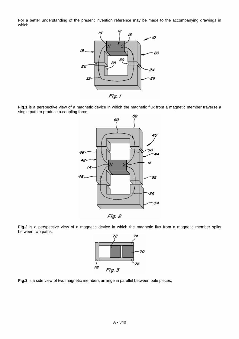
A - 340
For a better understanding of the present invention reference may be made to the accompanying drawings in which:
Fig.1 is a perspective view of a magnetic device in which the magnetic flux from a magnetic member traverse a single path to produce a coupling force;
Fig.2 is a perspective view of a magnetic device in which the magnetic flux from a magnetic member splits between two paths;
Fig.3 is a side view of two magnetic members arrange in parallel between pole pieces;
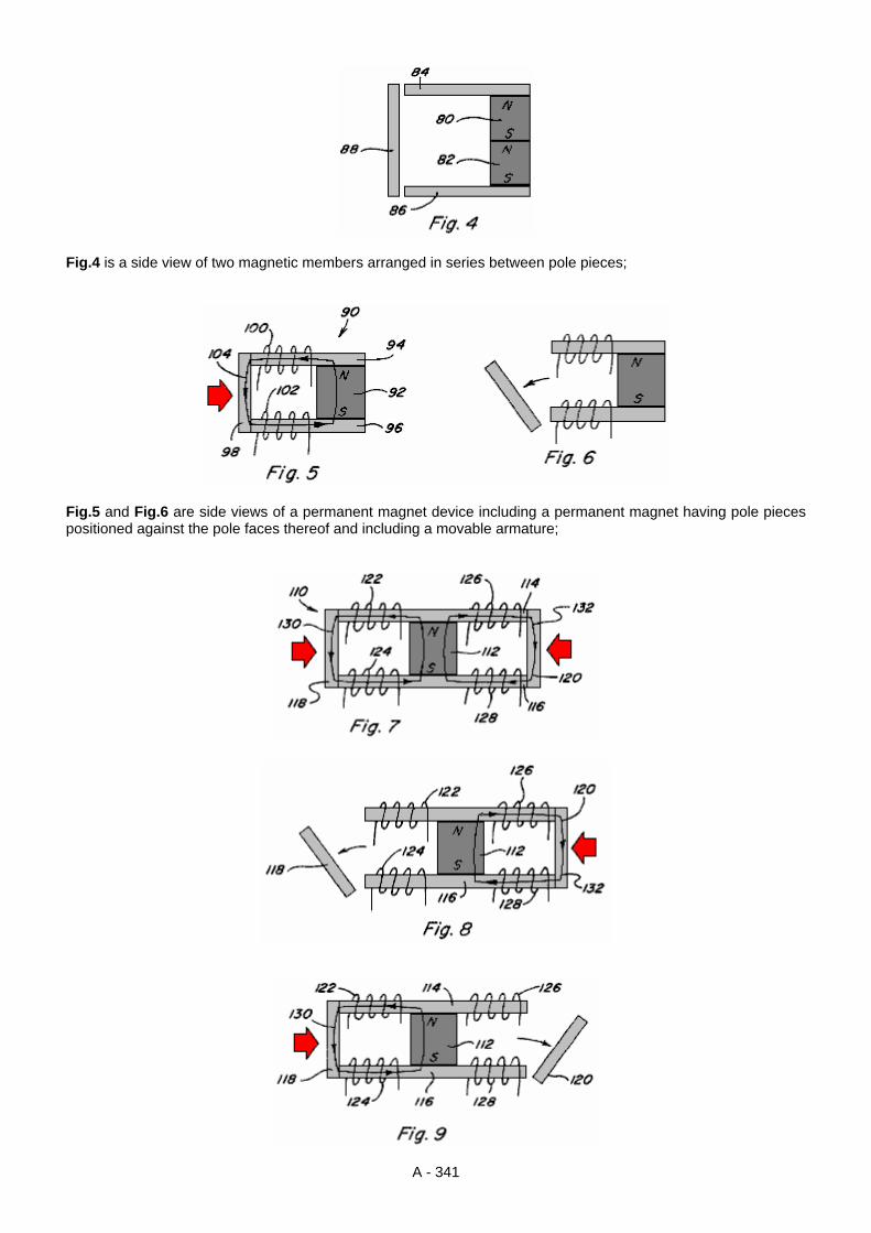
A - 341
Fig.4 is a side view of two magnetic members arranged in series between pole pieces;
Fig.5 and Fig.6 are side views of a permanent magnet device including a permanent magnet having pole pieces positioned against the pole faces thereof and including a movable armature;

A - 342
Fig.7, Fig.8 and Fig.9 are side views of a permanent magnet device including a permanent magnet having pole pieces positioned against the pole faces thereof to provide two magnetic flux paths and including a movable armature which can be positioned along each magnetic flux path;
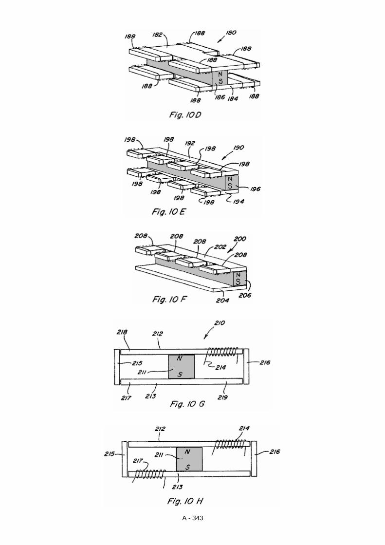
A - 343
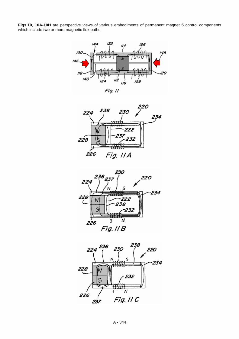
A - 344
Figs.10, 10A-10H are perspective views of various embodiments of permanent magnet 5 control components which include two or more magnetic flux paths;
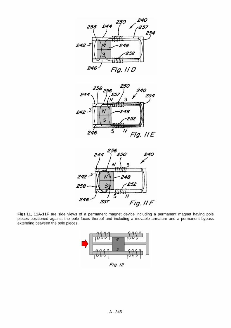
A - 345
Figs.11, 11A-11F are side views of a permanent magnet device including a permanent magnet having pole pieces positioned against the pole faces thereof and including a movable armature and a permanent bypass extending between the pole pieces;
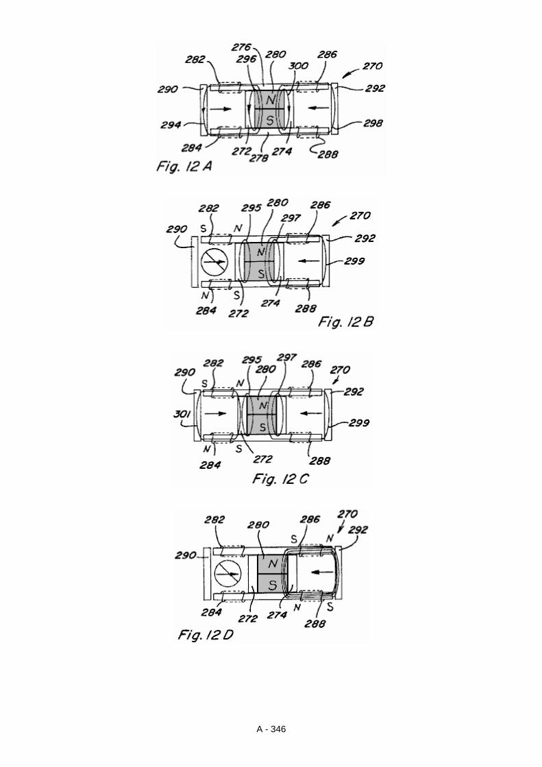
A - 346

A - 347
Figs.12, 12A-12E are side views of a two path permanent magnet device including two bypasses;
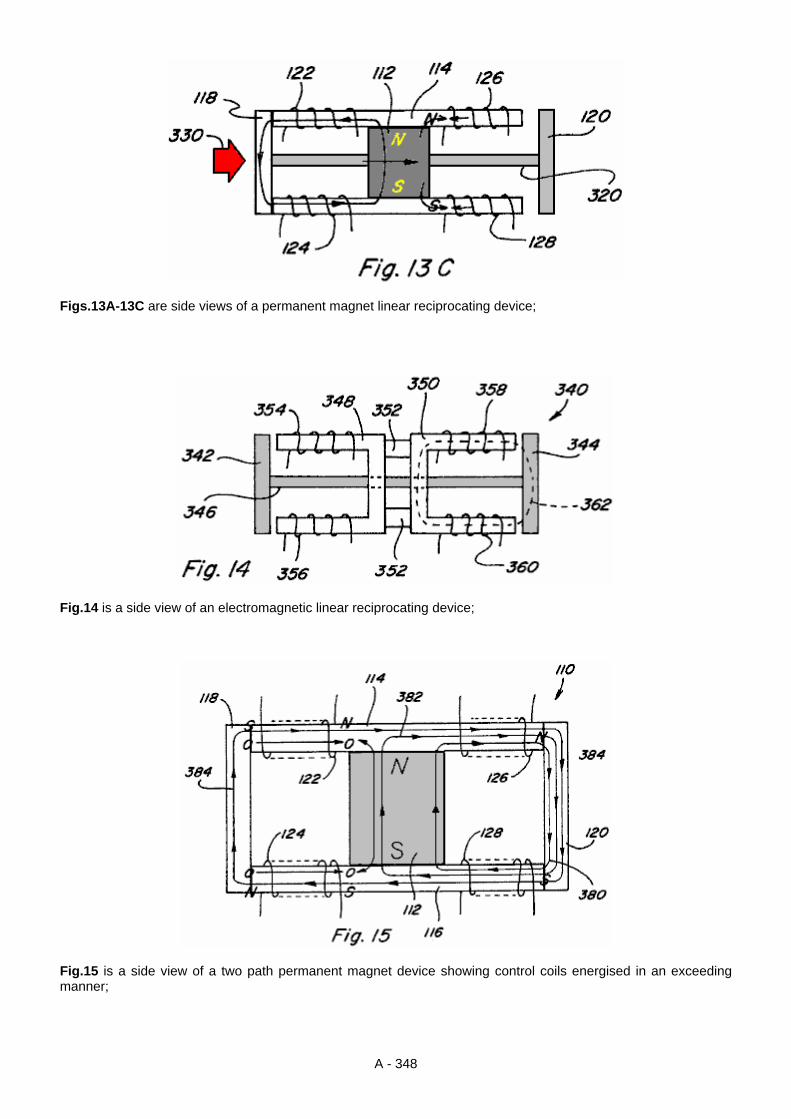
A - 348
Figs.13A-13C are side views of a permanent magnet linear reciprocating device;
Fig.14 is a side view of an electromagnetic linear reciprocating device;
Fig.15 is a side view of a two path permanent magnet device showing control coils energised in an exceeding manner;
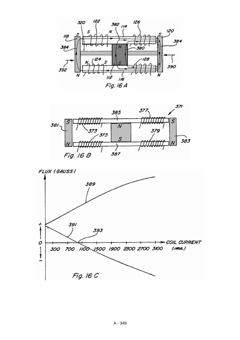
A - 349

A - 350
Figs.16A-E are a side view of a linear reciprocating device with control coils energised in an exceeding manner;
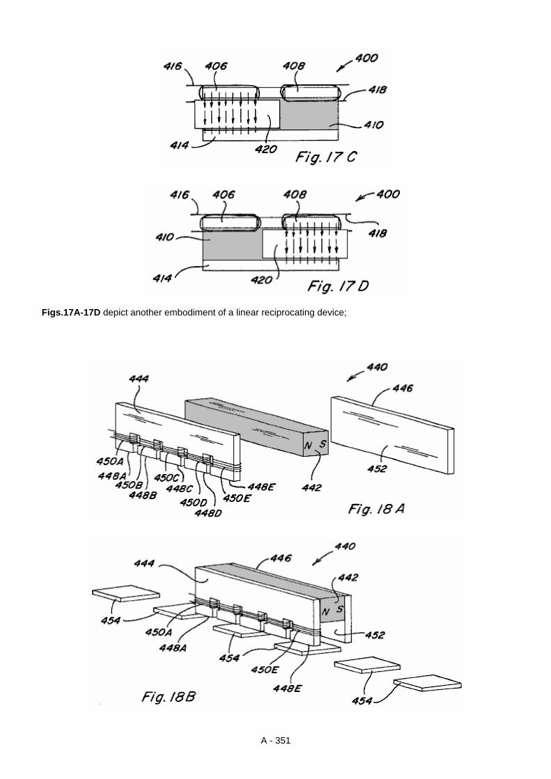
A - 351
Figs.17A-17D depict another embodiment of a linear reciprocating device;

A - 352
Figs.18A-18E show a linear motion device;

A - 353
Fig.19 is an exploded perspective view of a rotary motion device;
Fig.20 is a partial assembled and cut away view of the rotary motion device of Fig.19;
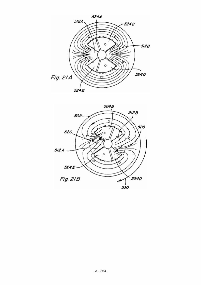
A - 354

A - 355
Figs.21A-21E are top views of the partial assembly of Fig.20, which views depict rotational motion thereof,

A - 356
Fig.22 is an assembled, cut-away view of the rotary motion device of Fig.19 including a housing;
Fig.23 is an exploded perspective view of another embodiment of a rotary motion device;
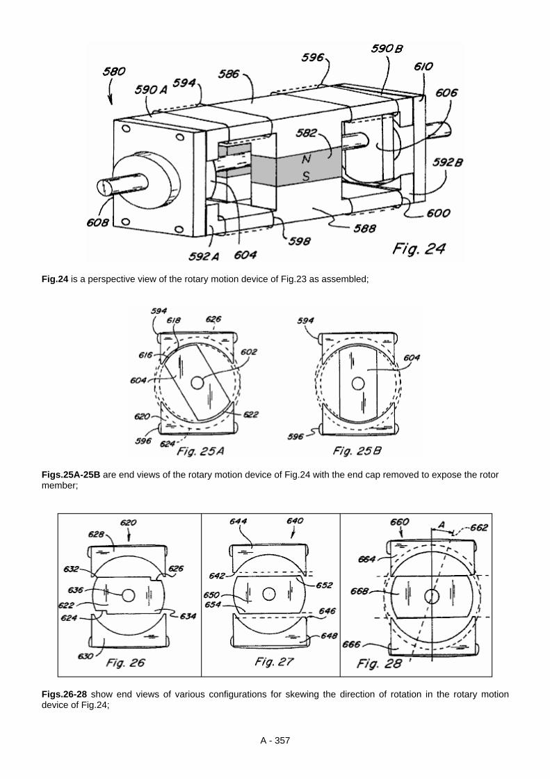
A - 357
Fig.24 is a perspective view of the rotary motion device of Fig.23 as assembled;
Figs.25A-25B are end views of the rotary motion device of Fig.24 with the end cap removed to expose the rotor member;
Figs.26-28 show end views of various configurations for skewing the direction of rotation in the rotary motion device of Fig.24;
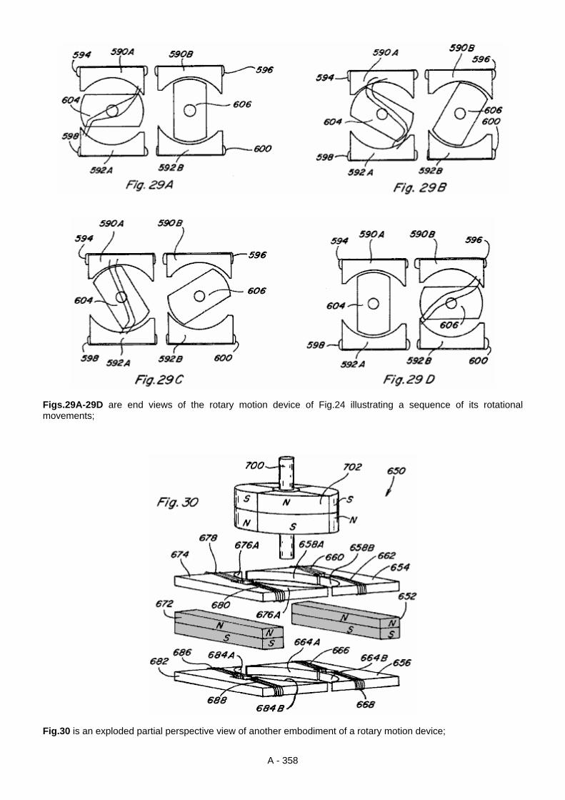
A - 358
Figs.29A-29D are end views of the rotary motion device of Fig.24 illustrating a sequence of its rotational movements;
Fig.30 is an exploded partial perspective view of another embodiment of a rotary motion device;
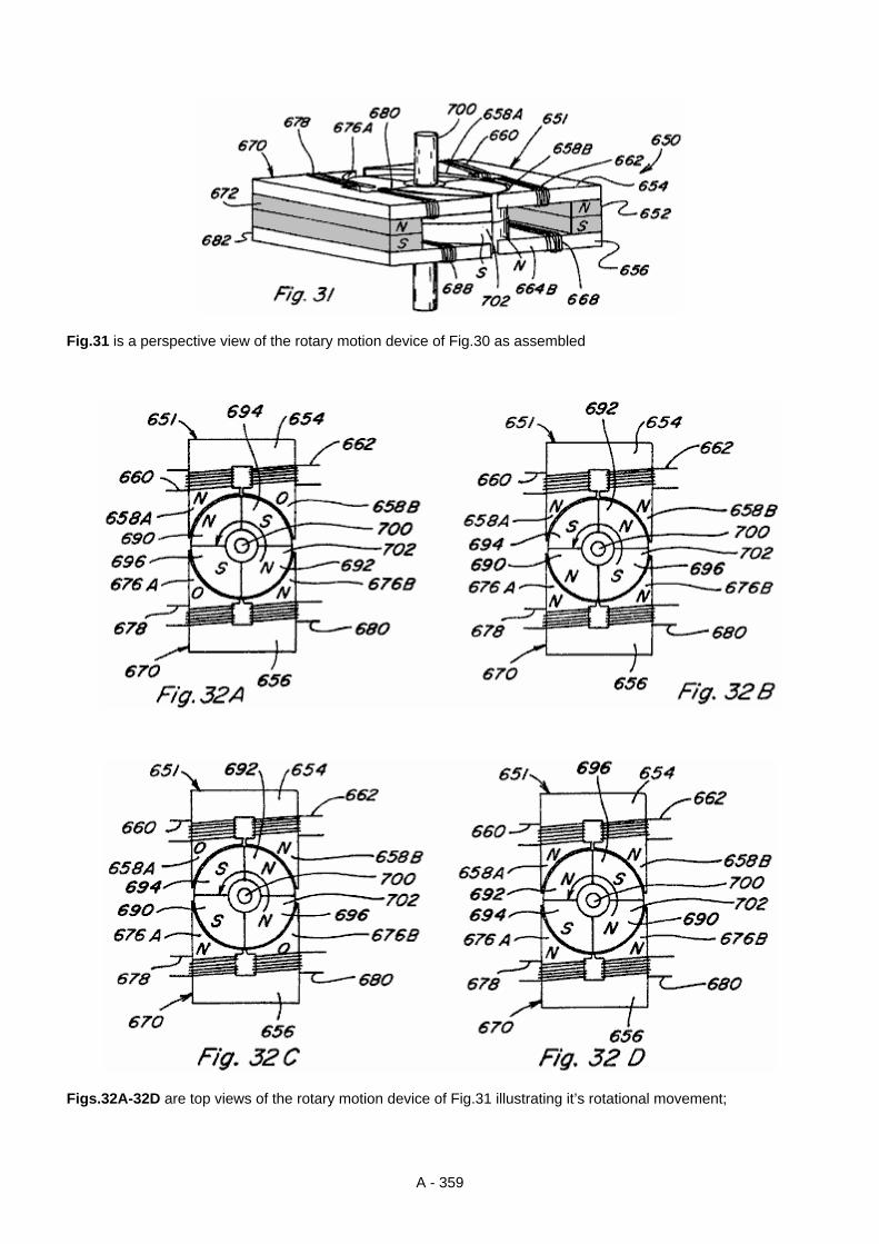
A - 359
Fig.31 is a perspective view of the rotary motion device of Fig.30 as assembled
Figs.32A-32D are top views of the rotary motion device of Fig.31 illustrating it’s rotational movement;
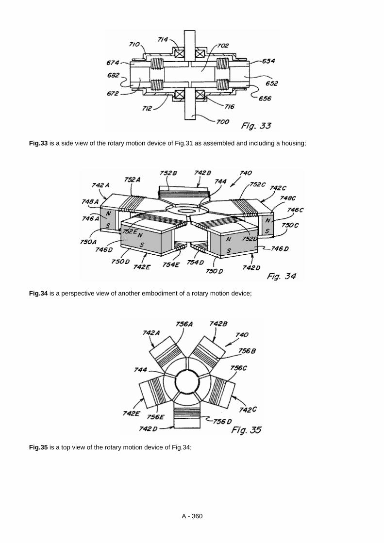
A - 360
Fig.33 is a side view of the rotary motion device of Fig.31 as assembled and including a housing;
Fig.34 is a perspective view of another embodiment of a rotary motion device;
Fig.35 is a top view of the rotary motion device of Fig.34;
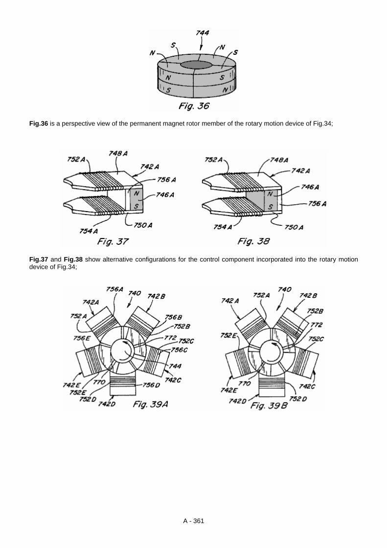
A - 361
Fig.36 is a perspective view of the permanent magnet rotor member of the rotary motion device of Fig.34;
Fig.37 and Fig.38 show alternative configurations for the control component incorporated into the rotary motion device of Fig.34;

A - 362
Figs.39A-39D are top views of the rotary motion device of Fig.34 and depict its rotational movement;

A - 363
Figs.40-44 are alternative variations of the circuit for controlling the timed energisation of control coils in the various devices of the present invention;

A - 364
Figs.45A-45C and Figs.45X-45Z are side views of two path power conversion devices;
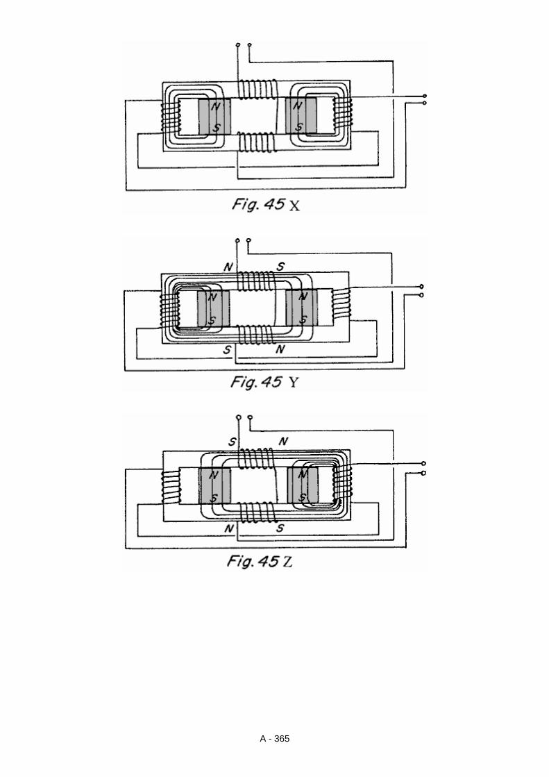
A - 365
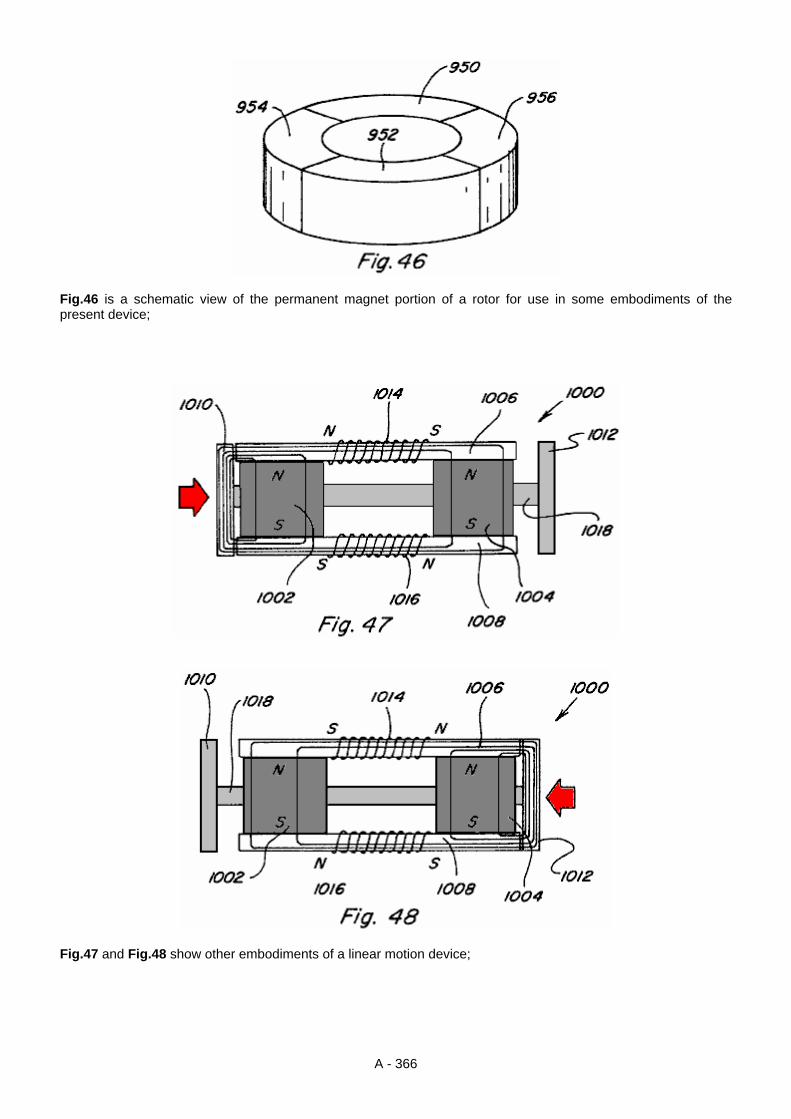
A - 366
Fig.46 is a schematic view of the permanent magnet portion of a rotor for use in some embodiments of the present device;
Fig.47 and Fig.48 show other embodiments of a linear motion device;

A - 367
Fig.49 is a top view of another embodiment of a rotating motor like construction; and
Fig.50 is a schematic view of one of the three stator portions of the device shown in Fig.49. DETAILED DESCRIPTION OF THE DRAWINGS

A - 368
Referring now to the drawings, Figs.1-4 are provided to facilitate an understanding of various aspects or features of the technology utilised in the present invention. Fig.1 depicts a device 10 having a magnetic flux producing member 12 which may be a permanent magnet or electromagnet with magnetic poles 14 and 16 as shown. Pole pieces 18 and 20 are positioned adjacent respective poles 14 and 16 to provide a path for the magnetic flux of member 12. Each pole piece 18 and 20 has a pole piece end face 22 and 24. As used throughout this specification, it is understood that a pole piece, regardless of its shape or size, is preferably formed of soft iron, steel or some other magnetic material, with the preferred material being one which provides low reluctance, exhibits low hysterisis, and has a high magnetic flux density capability. Accordingly, the various pole pieces disclosed and described herein could likewise be of laminate type construction. Referring again to Fig.1 an armature 26, also formed of magnetic material, is shown with end faces 28 and 30 which are positioned and sized for being placed adjacent pole piece end faces 22 and 24, such that when so positioned a substantially continuous low reluctance path 32 is provided for magnetic flux from north pole 14, through pole piece 18, through armature 26, through pole piece 16, and to south pole 16. The magnetic flux travelling along such path 32 results in a force which tends to hold armature 26 in position aligned with pole piece end faces 22 and 24. The resulting magnetic coupling or holding force F provided between adjacent pole piece end face 22 and armature end face 28, and between adjacent pole piece end face 24 and armature end face 30, can be approximated by the following equation:
where B is the magnetic flux density passing through the adjacent end faces and A is the surface area of the adjacent end faces. Assuming that if B is uniform throughout flux path 32 and that the area A of all end faces 22, 24, 28, and 30 is the same, then the total holding force FT26 of armature 26 against pole pieces 18 and 20 will be:

A - 369
In Fig.2 a device 40 having the same magnetic flux producing member 12 with magnetic poles 14 and 16 is shown. Pole pieces 42 and 44 are positioned adjacent respective pole faces 14 and 16 to provide two paths, as opposed to one above, for the magnetic flux of member 12. In particular, pole piece 42 includes a first path portion 46 extending beyond a perimeter of north pole face 14 in one direction and a second path portion 48 extending beyond the perimeter of north pole face 14 in another direction. Similarly, pole piece 44 includes a first path portion 50 extending beyond the perimeter of south pole face 16 in one direction and a second path portion 52 extending beyond the perimeter of south pole face 16 in another direction. Each pole piece path portion 46, 48, 50, 52 includes a respective end face. A first armature 54 which can be positioned adjacent to the end faces of pole piece path components 48 and 52 provides a first magnetic flux path 56 and a second armature 58 is which can be positioned adjacent the end faces of pole piece path components 46 and 50 provides a second magnetic flux path 60. If the flux carrying area along flux paths 56 and 60 is the same as the flux carrying area along flux path 32 of Fig.1, the magnetic flux density along each flux path 56 and 60 will be one-half the magnetic flux density along flux path 32 of Fig.1 because the same amount of flux is split between two like paths. The effect of dividing a given amount of magnetic flux along two like flux paths instead of it passing along just one flux path can be seen by examining the holding force on armature 54 as compared to the holding force on armature 26 of Fig.1. As already noted the magnetic flux density along path 56 will be one-half that along flux path 32 and thus the total holding force FT54 can be determined as:
It is therefore seen that dividing the same amount of magnetic flux along two flux paths rather than along one flux path reduces the magnetic holding or coupling force on an armature to one-fourth rather than one-half as might have been expected. This unexpected magnetic holding or coupling force differential, resulting from multiple flux paths, can provide advantageous properties in linear, reciprocating, and rotary motion devices.

A - 370
Referring now to Fig.3 and Fig.4, the behaviour of multiple magnetic flux sources arranged in parallel and series is described as compared to a single flux source. When identical flux sources or magnetic flux producing members 70 and 72 are positioned in parallel as shown in Fig.3 with pole pieces 74 and 76 positioned adjacent the poles thereof to provide a flux path through armature 78, the flux density B through armature 78 is double what the flux density would be if only one magnetic flux producing member were present. However, the field intensity H resulting from the two members 70 and 72 remains unchanged. This result holds true regardless of whether members 70 and 72 are both permanent magnets, are both electromagnets, or are a combination of one permanent magnet and one electromagnet. On the other hand, the properties resulting from magnetic flux producing members 80 and 82 arranged pole-to-pole in series between pole pieces 84 and 86, with armature 88, as shown in Fig.4, will vary depending on the nature of the members 80 and 82. In a first case, if both members 80 and 82 are permanent magnets, the magnetic field intensity H resulting from the two permanent magnets will be double that of one permanent magnet and the flux density B through armature 88 will be the same as what the flux density would be if only one permanent magnet type member were present. In a second case, if both members 80 and 82 are electromagnets, the field intensity H again doubles and the flux density B increases according to the B/H curve or relationship of the pole piece 84, 86 and armature 88 materials. In a third case, if member 80 is a permanent magnet and member 82 is an electromagnet, the field intensity H again doubles, but, since the permanent magnet is near flux density saturation Br the flux density can only be increased from Br to Bmax of the permanent magnet. At the point where electromagnet-type member 82 contacts permanent magnet-type member 80 the flux from the electromagnet-type member 82 couples with the flux of the permanent magnet-type member 82 until the flux density through permanent magnet-type member 80 reaches Bmax. At that point additional flux from electromagnet-type member 82 does not contribute to the flux density along the flux path unless a bypass path around the permanent magnet-type member is provided. Use of such bypass paths will be described below.
Controlling the flow of flux along both one and multiple flux paths is best described with reference to Figs.5-9. In Fig.5 and Fig.6 a permanent magnet device 90 including a permanent magnet 92 having pole pieces 94 and 96 positioned adjacent to it’s pole faces, and an armature 98 completing a low reluctance path 104 from pole to pole is shown. Control coils 100, 102 are positioned along path 104. When control coils 100, 102 are not energised, the magnetic flux of permanent magnet 92 follows path 104 as shown and armature 98 is held in place against

A - 371
pole pieces 94, 96 due to the resulting magnetic coupling forces. However, if coils 100, 102 are energised to provide an equal but opposing magnetic flux to that of permanent magnet 92, the result is that the magnetic flux of permanent magnet 92 is blocked and no magnetic flux traverses the path which includes armature 98 and therefore no magnetic coupling forces act on armature 98 allowing it to fall away as shown in Fig.6. The permanent magnet device 90 is useful, although as will become apparent below, it is more advantageous to provide multiple flux paths rather than one.
In this regard, in Fig.7 a permanent magnet device 110 includes a permanent magnet 112 having pole pieces 114, 116 positioned adjacent the pole faces of it, with armatures 118, 120 completing two low-reluctance paths 130, 132 from pole to pole thereof. Control coils 122, 124 are positioned along path 130 and control coils 126, 128 are positioned along path 132. The two paths provided are assumed to be of equal reluctance. With no coils energised, the magnetic flux of permanent magnet 112 divides equally along flux path 130 and flux path 132 such that both armatures 118, 120 are subjected to a magnetic coupling force which holds them in place against pole pieces 114, 116.
If coils 122, 124 are energised to provide a magnetic flux equal to but opposing the magnetic flux which travels along flux path 130 from permanent magnet 112 when no coils are energised, the result is that the magnetic flux of permanent magnet 112 is blocked and no magnetic flux traverses the path which includes armature 118 and therefore no magnetic coupling forces act on armature 118 allowing it to fall away as shown in Fig.8. Further, the magnetic flux traversing path 132 will be double that of when no coils are energised and therefore the magnetic coupling force on armature 120 will be about four (4) times that of when no coils are energised. By energising coils 126, 128 in an opposing manner a similar result would be achieved such that armature 120 would fall away and such that the magnetic coupling force on armature 118 would be increased. If coils 122, 124 are energised to provide a magnetic flux equal to and aiding the magnetic flux which travels along flux path 130 when no coils are energised, the result is that the control coils couple completely with the magnetic flux of permanent magnet 112 and no magnetic flux traverses the path which includes armature 120 and therefore no magnetic coupling forces act on armature 120 allowing it to fall away as shown in Fig.9. Further, the magnetic flux traversing path 130 will be double that of when no coils are energised and therefore the magnetic coupling force on armature 118 will be about four (4) times that when no coils are energised. By energising coils 126, 128 in an aiding manner a similar result would be achieved such that armature 118 would fall away and the magnetic coupling force on armature 120 would be increased. Based on the foregoing, it is seen that the full magnetic coupling force available from the permanent magnet 112, can be switched from one path to another path by the application of one half the power it would require for a coil alone to produce the same magnetic flux along one path. The ability to switch the full magnetic coupling force easily from one path to another, allows for efficient reciprocating, linear, and rotary motion and power conversion to be achieved.
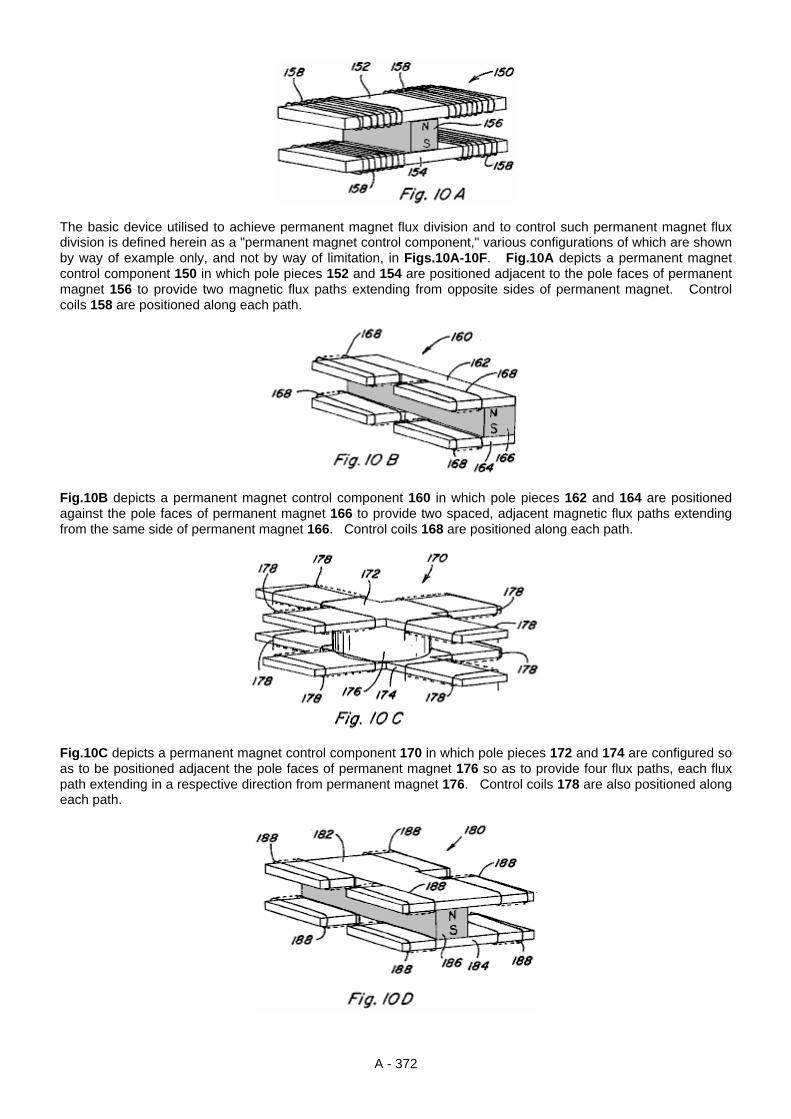
A - 372
The basic device utilised to achieve permanent magnet flux division and to control such permanent magnet flux division is defined herein as a "permanent magnet control component," various configurations of which are shown by way of example only, and not by way of limitation, in Figs.10A-10F. Fig.10A depicts a permanent magnet control component 150 in which pole pieces 152 and 154 are positioned adjacent to the pole faces of permanent magnet 156 to provide two magnetic flux paths extending from opposite sides of permanent magnet. Control coils 158 are positioned along each path.
Fig.10B depicts a permanent magnet control component 160 in which pole pieces 162 and 164 are positioned against the pole faces of permanent magnet 166 to provide two spaced, adjacent magnetic flux paths extending from the same side of permanent magnet 166. Control coils 168 are positioned along each path.
Fig.10C depicts a permanent magnet control component 170 in which pole pieces 172 and 174 are configured so as to be positioned adjacent the pole faces of permanent magnet 176 so as to provide four flux paths, each flux path extending in a respective direction from permanent magnet 176. Control coils 178 are also positioned along each path.
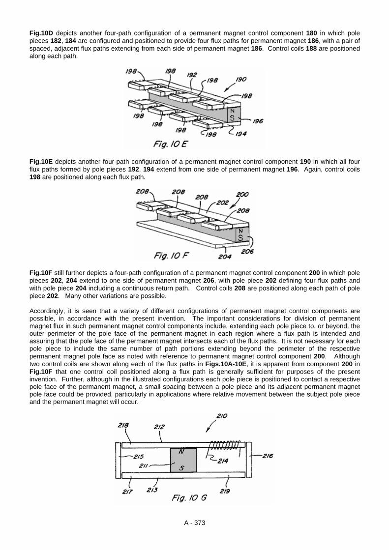
A - 373
Fig.10D depicts another four-path configuration of a permanent magnet control component 180 in which pole pieces 182, 184 are configured and positioned to provide four flux paths for permanent magnet 186, with a pair of spaced, adjacent flux paths extending from each side of permanent magnet 186. Control coils 188 are positioned along each path.
Fig.10E depicts another four-path configuration of a permanent magnet control component 190 in which all four flux paths formed by pole pieces 192, 194 extend from one side of permanent magnet 196. Again, control coils 198 are positioned along each flux path.
Fig.10F still further depicts a four-path configuration of a permanent magnet control component 200 in which pole pieces 202, 204 extend to one side of permanent magnet 206, with pole piece 202 defining four flux paths and with pole piece 204 including a continuous return path. Control coils 208 are positioned along each path of pole piece 202. Many other variations are possible. Accordingly, it is seen that a variety of different configurations of permanent magnet control components are possible, in accordance with the present invention. The important considerations for division of permanent magnet flux in such permanent magnet control components include, extending each pole piece to, or beyond, the outer perimeter of the pole face of the permanent magnet in each region where a flux path is intended and assuring that the pole face of the permanent magnet intersects each of the flux paths. It is not necessary for each pole piece to include the same number of path portions extending beyond the perimeter of the respective permanent magnet pole face as noted with reference to permanent magnet control component 200. Although two control coils are shown along each of the flux paths in Figs.10A-10E, it is apparent from component 200 in Fig.10F that one control coil positioned along a flux path is generally sufficient for purposes of the present invention. Further, although in the illustrated configurations each pole piece is positioned to contact a respective pole face of the permanent magnet, a small spacing between a pole piece and its adjacent permanent magnet pole face could be provided, particularly in applications where relative movement between the subject pole piece and the permanent magnet will occur.
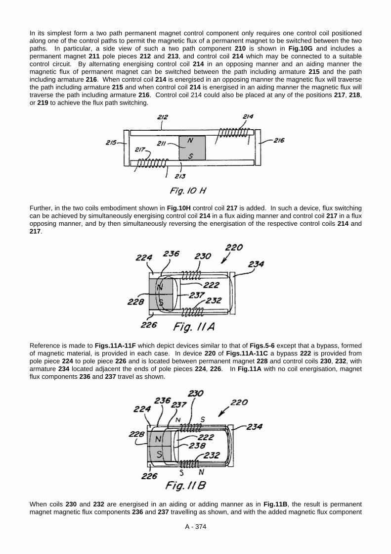
A - 374
In its simplest form a two path permanent magnet control component only requires one control coil positioned along one of the control paths to permit the magnetic flux of a permanent magnet to be switched between the two paths. In particular, a side view of such a two path component 210 is shown in Fig.10G and includes a permanent magnet 211 pole pieces 212 and 213, and control coil 214 which may be connected to a suitable control circuit. By alternating energising control coil 214 in an opposing manner and an aiding manner the magnetic flux of permanent magnet can be switched between the path including armature 215 and the path including armature 216. When control coil 214 is energised in an opposing manner the magnetic flux will traverse the path including armature 215 and when control coil 214 is energised in an aiding manner the magnetic flux will traverse the path including armature 216. Control coil 214 could also be placed at any of the positions 217, 218, or 219 to achieve the flux path switching.
Further, in the two coils embodiment shown in Fig.10H control coil 217 is added. In such a device, flux switching can be achieved by simultaneously energising control coil 214 in a flux aiding manner and control coil 217 in a flux opposing manner, and by then simultaneously reversing the energisation of the respective control coils 214 and 217.
Reference is made to Figs.11A-11F which depict devices similar to that of Figs.5-6 except that a bypass, formed of magnetic material, is provided in each case. In device 220 of Figs.11A-11C a bypass 222 is provided from pole piece 224 to pole piece 226 and is located between permanent magnet 228 and control coils 230, 232, with armature 234 located adjacent the ends of pole pieces 224, 226. In Fig.11A with no coil energisation, magnet flux components 236 and 237 travel as shown.
When coils 230 and 232 are energised in an aiding or adding manner as in Fig.11B, the result is permanent magnet magnetic flux components 236 and 237 travelling as shown, and with the added magnetic flux component

A - 375
238 from coils 230 and 232 also travelling as shown. Thus, in device 220 energising the coils in an aiding manner results in an increased magnetic coupling force on armature 234.
In Fig.11C coils 230, 232 are energised in an opposing exceeding manner which results in permanent magnetic flux components 236 and 237 travelling as shown and excess magnetic flux component 238 travelling as shown. Thus, in device 220 energising the coils in an opposing exceeding manner results in magnetic coupling force on armature 234, albeit smaller than that in the aiding exceeding case.
In device 240 of Figs.11D-11F a bypass 242 is provided between pole piece 244 and pole piece 246 but is located on an opposite side of permanent magnet 248 as compared to control coils 250, 252 and armature 254. Permanent magnet flux components 256 and 257 are shown for no coil energisation in Fig.11D. In Fig.11E the paths of permanent magnet flux components 256 and 257, as well as excess coil magnetic flux 258, are shown when coils 250, 252 are energised in an aiding exceeding manner.

A - 376
In Fig.11F the path of each magnetic flux component 256, 257, and 258 is shown when coils 230, 232 are energised in an opposed exceeding manner.
Figs.12A-12E depict a device 270 similar to that shown in Figs.7-9 except that bypasses 272 and 274 are provided from pole piece 276 to pole piece 278. Bypass 272 is located between permanent magnet 280 and control coils 282, 284 and bypass 274 is located between permanent magnet 280 and control coils 286, 288. Armatures 290 and 292 are also provided. When no coils are energised permanent magnet magnetic flux components 294, 296, 298, and 300 travel as shown in Fig.12A.
If coils 282, 284 are energised in an opposing manner permanent magnet flux components 295, 297, and 299 travel as shown, with no flux component traversing the path which includes armature 290 and therefore no magnetic coupling force acting thereon. This would be the case when coils 282, 284 are energised to the level where the coils magnetic flux just blocks, but does not exceed, the magnetic flux component 294 (Fig.12A) from permanent magnet 280. However, if coils 282, 284 are energised in an opposed exceeding manner an excess coil magnetic flux component 301 is produced which travels a path including armature 290 and bypass 272 results as shown in Fig.12C.
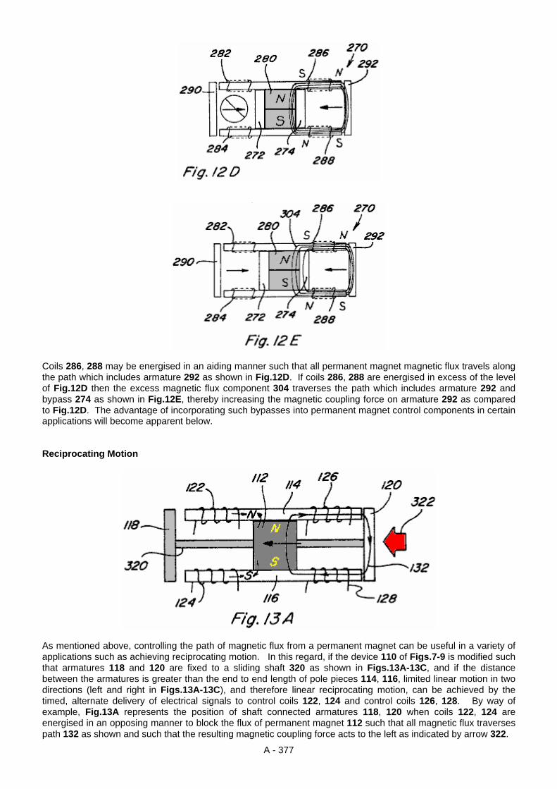
A - 377
Coils 286, 288 may be energised in an aiding manner such that all permanent magnet magnetic flux travels along the path which includes armature 292 as shown in Fig.12D. If coils 286, 288 are energised in excess of the level of Fig.12D then the excess magnetic flux component 304 traverses the path which includes armature 292 and bypass 274 as shown in Fig.12E, thereby increasing the magnetic coupling force on armature 292 as compared to Fig.12D. The advantage of incorporating such bypasses into permanent magnet control components in certain applications will become apparent below. Reciprocating Motion
As mentioned above, controlling the path of magnetic flux from a permanent magnet can be useful in a variety of applications such as achieving reciprocating motion. In this regard, if the device 110 of Figs.7-9 is modified such that armatures 118 and 120 are fixed to a sliding shaft 320 as shown in Figs.13A-13C, and if the distance between the armatures is greater than the end to end length of pole pieces 114, 116, limited linear motion in two directions (left and right in Figs.13A-13C), and therefore linear reciprocating motion, can be achieved by the timed, alternate delivery of electrical signals to control coils 122, 124 and control coils 126, 128. By way of example, Fig.13A represents the position of shaft connected armatures 118, 120 when coils 122, 124 are energised in an opposing manner to block the flux of permanent magnet 112 such that all magnetic flux traverses path 132 as shown and such that the resulting magnetic coupling force acts to the left as indicated by arrow 322.
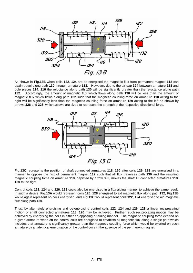
A - 378
As shown in Fig.13B when coils 122, 124 are de-energised the magnetic flux from permanent magnet 112 can again travel along path 130 through armature 118. However, due to the air gap 324 between armature 118 and pole pieces 114, 116 the reluctance along path 130 will be significantly greater than the reluctance along path 132. Accordingly, the amount of magnetic flux which flows along path 130 will be less than the amount of magnetic flux which flows along path 132 such that the magnetic coupling force on armature 118 acting to the right will be significantly less than the magnetic coupling force on armature 120 acting to the left as shown by arrows 326 and 328, which arrows are sized to represent the strength of the respective directional force.
Fig.13C represents the position of shaft connected armatures 118, 120 after coils 126, 128 are energised in a manner to oppose the flux of permanent magnet 112 such that all flux traverses path 130 and the resulting magnetic coupling force on armature 118, depicted by arrow 330, moves the shaft 10 connected armatures 118, 120 to the right. Control coils 122, 124 and 126, 128 could also be energised in a flux aiding manner to achieve the same result. In such a device, Fig.13A would represent coils 126, 128 energised to aid magnetic flux along path 132, Fig.13B would again represent no coils energised, and Fig.13C would represent coils 122, 124 energised to aid magnetic flux along path 130. Thus, by alternately energising and de-energising control coils 122, 124 and 126, 128 a linear reciprocating motion of shaft connected armatures 118, 120 may be achieved. Further, such reciprocating motion may be achieved by energising the coils in either an opposing or aiding manner. The magnetic coupling force exerted on a given armature when 20 the control coils are energised to establish all magnetic flux along a single path which includes that armature is significantly greater than the magnetic coupling force which would be exerted on such armature by an identical energisation of the control coils in the absence of the permanent magnet.
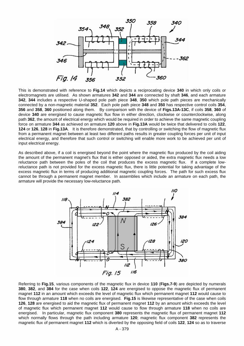
A - 379
This is demonstrated with reference to Fig.14 which depicts a reciprocating device 340 in which only coils or electromagnets are utilised. As shown armatures 342 and 344 are connected by shaft 346, and each armature 342, 344 includes a respective U-shaped pole path piece 348, 350 which pole path pieces are mechanically connected by a non-magnetic material 352. Each pole path piece 348 and 350 has respective control coils 354, 356 and 358, 360 positioned along them. By comparison with the device of Figs.13A-13C, if coils 358, 360 of device 340 are energised to cause magnetic flux flow in either direction, clockwise or counterclockwise, along path 362, the amount of electrical energy which would be required in order to achieve the same magnetic coupling force on armature 344 as achieved on armature 120 above in Fig.13A would be twice that delivered to coils 122, 124 or 126, 128 in Fig.13A. It is therefore demonstrated, that by controlling or switching the flow of magnetic flux from a permanent magnet between at least two different paths results in greater coupling forces per unit of input electrical energy, and therefore that such control or switching will enable more work to be achieved per unit of input electrical energy. As described above, if a coil is energised beyond the point where the magnetic flux produced by the coil aiding the amount of the permanent magnet's flux that is either opposed or aided, the extra magnetic flux needs a low reluctance path between the poles of the coil that produces the excess magnetic flux. If a complete low-reluctance path is not provided for the excess magnetic flux, there is little potential for taking advantage of the excess magnetic flux in terms of producing additional magnetic coupling forces. The path for such excess flux cannot be through a permanent magnet member. In assemblies which include an armature on each path, the armature will provide the necessary low-reluctance path.
Referring to Fig.15, various components of the magnetic flux in device 110 (Figs.7-9) are depicted by numerals 380, 382, and 384 for the case when coils 122, 124 are energised to oppose the magnetic flux of permanent magnet 112 in an amount which exceeds the level of magnetic flux which permanent magnet 112 would cause to flow through armature 118 when no coils are energised. Fig.15 is likewise representative of the case when coils 126, 128 are energised to aid the magnetic flux of permanent magnet 112 by an amount which exceeds the level of magnetic flux which permanent magnet 112 would cause to flow through armature 118 when no coils are energised. In particular, magnetic flux component 380 represents the magnetic flux of permanent magnet 112 which normally flows through the path including armature 120; magnetic flux component 382 represents the magnetic flux of permanent magnet 112 which is diverted by the opposing field of coils 122, 124 so as to traverse

A - 380
the path which includes armature 120; and magnetic flux component 384 represents the magnetic flux produced by coils 122, 124 which is in excess of the diverted magnetic flux 382. As shown, the excess magnetic flux 384 produced by coils 122, 124 traverses the path which includes armature 120 and bypasses permanent magnet 112 so as to also traverse the path which includes armature 118. Thus, the excess magnetic flux produced by coils 122, 124 adds to the permanent magnet flux traversing the path which includes armature 120, thus increasing the magnetic coupling force on armature 120, while at the same time providing a magnetic coupling force on armature 118.
In a reciprocating device where armatures 118 and 120 are connected by shaft 320 as shown in Figs.13A-13C and again in Fig.16A, excess magnetic flux 384 will increase magnetic coupling force 390 on armature 120 acting to the left. However, because such excess flux 384 also traverses the path which includes armature 118, such excess magnetic flux 384 also results in a magnetic coupling force 392 on armature 118 which acts to the right. Even though excess magnetic flux 384 traversing the path which includes an armature 118 has an opposite polarity to that which would traverse the path due to permanent magnet 112, the magnetic coupling force on armature 118 still acts to the right because armature 118 is not polarity sensitive, that is, armature 118 will be attracted regardless of the direction of the magnetic flux traversing the path. The overall effect is that a resultant force which is the difference between force 390 and force 392 will act on the shaft-connected armatures 118, 120. However, if armatures 118 and 120 were formed by permanent magnets having polarities as shown at the top and bottom of such armatures, the force acting on each armature would be in the same direction and therefore additive.
In this regard reference is made to Fig.16B in which a two path device 371 having four control coils 373, 375, 377 and 379 is shown with the illustrated armatures being formed by permanent magnets 381 and 383 having polarities as shown. With no coils energised both permanent magnet armatures 381 and 383 are attracted to the ends of pole pieces 385 and 387. With coils 373, 375 energised in an opposing manner and coils 377, 379 energised in an aiding manner, the attractive force on permanent magnet armature 383 will generally increase and the attractive force on permanent magnet armature 381 will generally decrease.
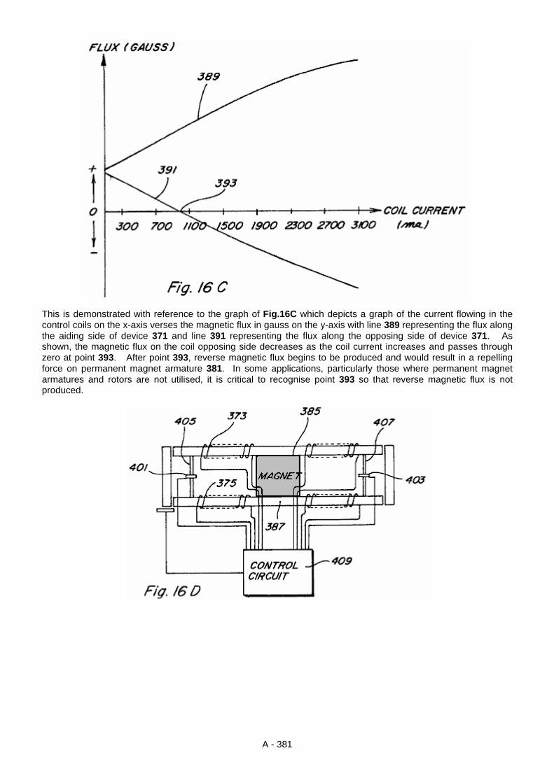
A - 381
This is demonstrated with reference to the graph of Fig.16C which depicts a graph of the current flowing in the control coils on the x-axis verses the magnetic flux in gauss on the y-axis with line 389 representing the flux along the aiding side of device 371 and line 391 representing the flux along the opposing side of device 371. As shown, the magnetic flux on the coil opposing side decreases as the coil current increases and passes through zero at point 393. After point 393, reverse magnetic flux begins to be produced and would result in a repelling force on permanent magnet armature 381. In some applications, particularly those where permanent magnet armatures and rotors are not utilised, it is critical to recognise point 393 so that reverse magnetic flux is not produced.
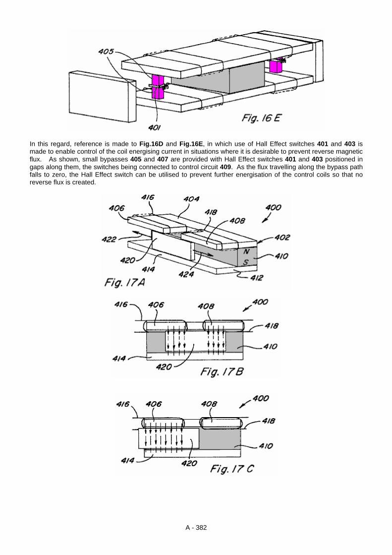
A - 382
In this regard, reference is made to Fig.16D and Fig.16E, in which use of Hall Effect switches 401 and 403 is made to enable control of the coil energising current in situations where it is desirable to prevent reverse magnetic flux. As shown, small bypasses 405 and 407 are provided with Hall Effect switches 401 and 403 positioned in gaps along them, the switches being connected to control circuit 409. As the flux travelling along the bypass path falls to zero, the Hall Effect switch can be utilised to prevent further energisation of the control coils so that no reverse flux is created.
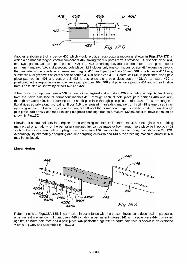
A - 383
Another embodiment of a device 400 which would provide reciprocating motion is shown in Figs.17A-17D in which a permanent magnet control component 402 having two flux paths may is provided. A first pole piece 404, has two spaced, adjacent path portions 406 and 408 extending beyond the perimeter of the pole face of permanent magnet 410, and a second pole piece 412 includes only one continuous portion 414 extending beyond the perimeter of the pole face of permanent magnet 410, each path portion 406 and 408 of pole piece 404 being substantially aligned with at least a part of portion 414 of pole piece 412. Control coil 416 is positioned along pole piece path portion 406 and control coil 418 is positioned along pole piece portion 408. An armature 420 is positioned in the region between pole piece path portions 404, 406 and pole piece portion 414 and is free to slide from side to side as shown by arrows 422 and 424. A front view of component device 400 with no coils energised and armature 420 at a mid-point depicts flux flowing from the north pole face of permanent magnet 410, through each of pole piece path portions 406 and 408, through armature 420, and returning to the south pole face through pole piece portion 414. Thus, the magnetic flux divides equally along two paths. If coil 416 is energised in an aiding manner, or if coil 418 is energised in an opposing manner, all or a majority of the magnetic flux of the permanent magnets can be made to flow through pole piece portion 406 so that a resulting magnetic coupling force on armature 420 causes it to move to the left as shown in Fig.17C. Likewise, if control coil 416 is energised in an opposing manner, or if control coil 418 is energised in an aiding manner, all or a majority of the permanent magnet flux can be made to flow through pole piece path portion 408 such that a resulting magnetic coupling force on armature 420 causes it to move to the right as shown in Fig.17D. Accordingly, by alternately energising and de-energising coils 416 and 418 a reciprocating motion of armature 420 may be achieved. Linear Motion
Referring now to Figs.18A-18E, linear motion in accordance with the present invention is described. In particular, a permanent magnet control component 440 including a permanent magnet 442 with a pole piece 444 positioned against it’s north pole face and a pole piece 446 positioned against it’s south pole face is shown in an exploded view in Fig.18A and assembled in Fig.18B.
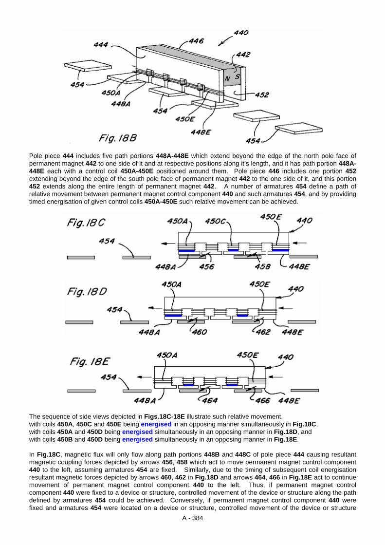
A - 384
Pole piece 444 includes five path portions 448A-448E which extend beyond the edge of the north pole face of permanent magnet 442 to one side of it and at respective positions along it’s length, and it has path portion 448A-448E each with a control coil 450A-450E positioned around them. Pole piece 446 includes one portion 452 extending beyond the edge of the south pole face of permanent magnet 442 to the one side of it, and this portion 452 extends along the entire length of permanent magnet 442. A number of armatures 454 define a path of relative movement between permanent magnet control component 440 and such armatures 454, and by providing timed energisation of given control coils 450A-450E such relative movement can be achieved.
The sequence of side views depicted in Figs.18C-18E illustrate such relative movement, with coils 450A, 450C and 450E being energised in an opposing manner simultaneously in Fig.18C, with coils 450A and 450D being energised simultaneously in an opposing manner in Fig.18D, and with coils 450B and 450D being energised simultaneously in an opposing manner in Fig.18E. In Fig.18C, magnetic flux will only flow along path portions 448B and 448C of pole piece 444 causing resultant magnetic coupling forces depicted by arrows 456, 458 which act to move permanent magnet control component 440 to the left, assuming armatures 454 are fixed. Similarly, due to the timing of subsequent coil energisation resultant magnetic forces depicted by arrows 460, 462 in Fig.18D and arrows 464, 466 in Fig.18E act to continue movement of permanent magnet control component 440 to the left. Thus, if permanent magnet control component 440 were fixed to a device or structure, controlled movement of the device or structure along the path defined by armatures 454 could be achieved. Conversely, if permanent magnet control component 440 were fixed and armatures 454 were located on a device or structure, controlled movement of the device or structure

A - 385
could also be achieved. It is also easily recognised that by varying the coil energisation sequence and timing relative movement in the opposite direction can be achieved. Further, if the permanent magnet was doughnut shaped and the armatures were arranged in a circumferential pattern, rotary motion would likewise be achievable. Rotary Motion
One embodiment of a rotary motion device or motor 500 which incorporates various permanent magnet flux control aspects of the present invention is shown in the exploded view of Fig.19 and in the partial assembled view of Fig.20. Motor 500 includes a rotor assembly which includes a shaft 502 and associated upper bearing 504, a non-magnetic disk member 506 mounted for rotation with shaft 502, and a rotor pole piece 508 which is mounted for rotation with disk member 506 such as by the use of screws 510. Rotor pole piece 508 includes a ring-shaped portion having two inwardly extending magnetic flux path portions 512A and 512B. A stator assembly of motor 500 includes a doughnut or ring-shaped permanent magnet 514 having an upwardly directed north pole face positioned adjacent and in close proximity to rotor pole piece 508, and a downward directed south pole face positioned adjacent and in contact with a stator pole piece 516. Stator pole piece includes a ring-shaped portion having five inwardly projecting path portions 518A-518E. Each path portion includes a respective winding post 520A-520E extending therefrom and having a respective control coil 522A-522E wound on it. Stator pole piece faces 524A-524E are which can be positioned on respective winding posts 518A-518B and, as shown in the partial assembly of Fig.20, are substantially aligned with the top surface of permanent magnet 514 so as to be which can be positioned adjacent rotor path portions 512A and 512B when aligned therewith. Each of winding posts 518A-518E and stator pole piece faces are formed of magnetic material, and although shown as separate pieces, an integral, one piece stator could be formed with similar winding posts and pole piece faces machined on it. Lower bearing 526 is also shown.

A - 386
Figs.21A-21E illustrate top views of the partial assembly of Fig.20 with magnetic flux shown. In Fig.21A magnetic flux travel when none of coils 522A-522E are energised is depicted. Disregarding leakage flux, due to the low-reluctance path provided by rotor pole piece path portions 512A and 512B, the majority of magnetic flux from the north pole face of permanent magnet 514 will travel radially inward along one of such path portions before passing downward through the stator assembly and returning to the south pole face of permanent magnet 514. It is noted that rotor pole piece 508 includes two path portions and stator pole piece 516 includes five path portions such that rotor pole piece path portions 512A and 512B will always be skewed relative to the stator pole piece faces 524A-524E. Only one rotor pole piece path portion can directly align with a stator pole piece face at a given time. By alternately energising the control coils of each of the stator pole piece paths, rotary motion of the rotor may be achieved.
In particular, referring to Figs.21B-21D, an energising sequence which results in such rotary motion is described. In Fig.21B, control coils 522A and 522C are energised in a permanent magnet flux opposing manner. Permanent magnet magnetic flux travelling along rotor pole piece path portion 512A tends to traverse to stator pole piece face 524B causing a magnetic coupling force indicated by arrow 526. Likewise, permanent magnet flux travelling along rotor pole piece path portion 512B tends to traverse to stator pole piece face 524D causing a magnetic coupling force indicated by arrow 528. The result is rotation of rotor pole piece 508 in a clockwise direction as indicated by arrow 530.

A - 387
Referring to Fig.21C, just after rotor pole piece path portion 512B is no longer aligned with stator pole piece face 524D, control coil 522C is de-energised and control coil 522D is energised in an opposing manner such that the permanent magnet flux travelling along rotor pole piece path 512B tends to traverse to stator pole piece face 524E resulting in magnetic coupling force indicated by arrow 532. Control coil 522A remains energised such that a magnetic coupling force indicated by arrow 534 results. Accordingly, clockwise rotation of rotor pole piece 508 is continued.
In Fig.21D, just after rotor pole piece path portion 512A is no longer aligned with stator pole piece face 524B, control coil 522A is de-energised and control coil 522B is energised in a permanent magnet magnetic flux opposing manner such that the permanent magnet magnetic flux travelling along rotor pole piece path 512A tends to traverse to stator pole piece face 524C such that a magnetic coupling force indicated by arrow 536 results. Control coil 522D remains energised such that a magnetic coupling force indicated by arrow 538 results, and clockwise rotation of rotor pole piece 508 is continued.
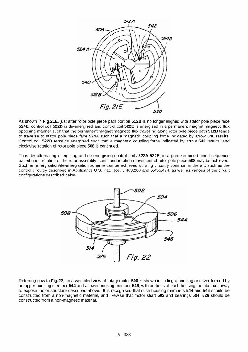
A - 388
As shown in Fig.21E, just after rotor pole piece path portion 512B is no longer aligned with stator pole piece face 524E, control coil 522D is de-energised and control coil 522E is energised in a permanent magnet magnetic flux opposing manner such that the permanent magnet magnetic flux travelling along rotor pole piece path 512B tends to traverse to stator pole piece face 524A such that a magnetic coupling force indicated by arrow 540 results. Control coil 522B remains energised such that a magnetic coupling force indicated by arrow 542 results, and clockwise rotation of rotor pole piece 508 is continued. Thus, by alternating energising and de-energising control coils 522A-522E, in a predetermined timed sequence based upon rotation of the rotor assembly, continued rotation movement of rotor pole piece 508 may be achieved. Such an energisation/de-energisation scheme can be achieved utilising circuitry common in the art, such as the control circuitry described in Applicant's U.S. Pat. Nos. 5,463,263 and 5,455,474, as well as various of the circuit configurations described below.
Referring now to Fig.22, an assembled view of rotary motor 500 is shown including a housing or cover formed by an upper housing member 544 and a lower housing member 546, with portions of each housing member cut away to expose motor structure described above. It is recognised that such housing members 544 and 546 should be constructed from a non-magnetic material, and likewise that motor shaft 502 and bearings 504, 526 should be constructed from a non-magnetic material.

A - 389
In another embodiment, a rotary motion device or motor 580 in accordance with the present invention is shown in an exploded perspective view in Fig.23 and in an assembled perspective view in Fig.24. Two spaced permanent magnets 582 and 584 are positioned between stator pole pieces 586 and 588. Stator pole piece 586 includes two path portions 590A and 590B extending away from permanent magnets 582, 584 in opposite directions. Likewise, stator pole piece 588 includes two path portions 592A and 592B extending away from permanent magnets 582, 584 in opposite directions and which can be aligned with stator pole piece path portions 590A and 590B. Control coils 594, 596, 598, and 600 are each positioned along a stator pole piece path portion as shown. A non-magnetic shaft 602 includes a pair of matching elongated rotor members 604 and 606, formed of magnetic material, mounted at spaced locations on the shaft and being set at an angle to each other, shaft 602 passing between spaced permanent magnets 582 and 584. Two end cap members 608 and 610, made from non-magnetic material, are attached to the ends of stator pole pieces 586 and 588 and are configured for receiving shaft 602 and respective bearings 612 and 614.
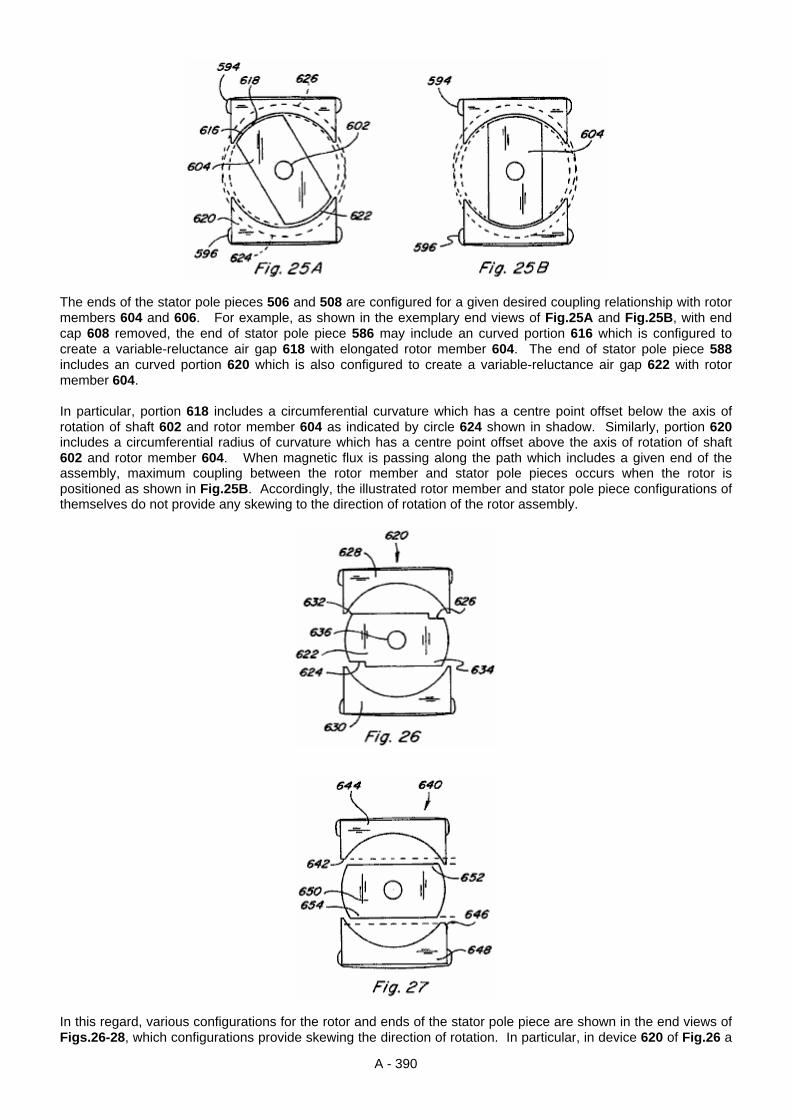
A - 390
The ends of the stator pole pieces 506 and 508 are configured for a given desired coupling relationship with rotor members 604 and 606. For example, as shown in the exemplary end views of Fig.25A and Fig.25B, with end cap 608 removed, the end of stator pole piece 586 may include an curved portion 616 which is configured to create a variable-reluctance air gap 618 with elongated rotor member 604. The end of stator pole piece 588 includes an curved portion 620 which is also configured to create a variable-reluctance air gap 622 with rotor member 604. In particular, portion 618 includes a circumferential curvature which has a centre point offset below the axis of rotation of shaft 602 and rotor member 604 as indicated by circle 624 shown in shadow. Similarly, portion 620 includes a circumferential radius of curvature which has a centre point offset above the axis of rotation of shaft 602 and rotor member 604. When magnetic flux is passing along the path which includes a given end of the assembly, maximum coupling between the rotor member and stator pole pieces occurs when the rotor is positioned as shown in Fig.25B. Accordingly, the illustrated rotor member and stator pole piece configurations of themselves do not provide any skewing to the direction of rotation of the rotor assembly.
In this regard, various configurations for the rotor and ends of the stator pole piece are shown in the end views of Figs.26-28, which configurations provide skewing the direction of rotation. In particular, in device 620 of Fig.26 a
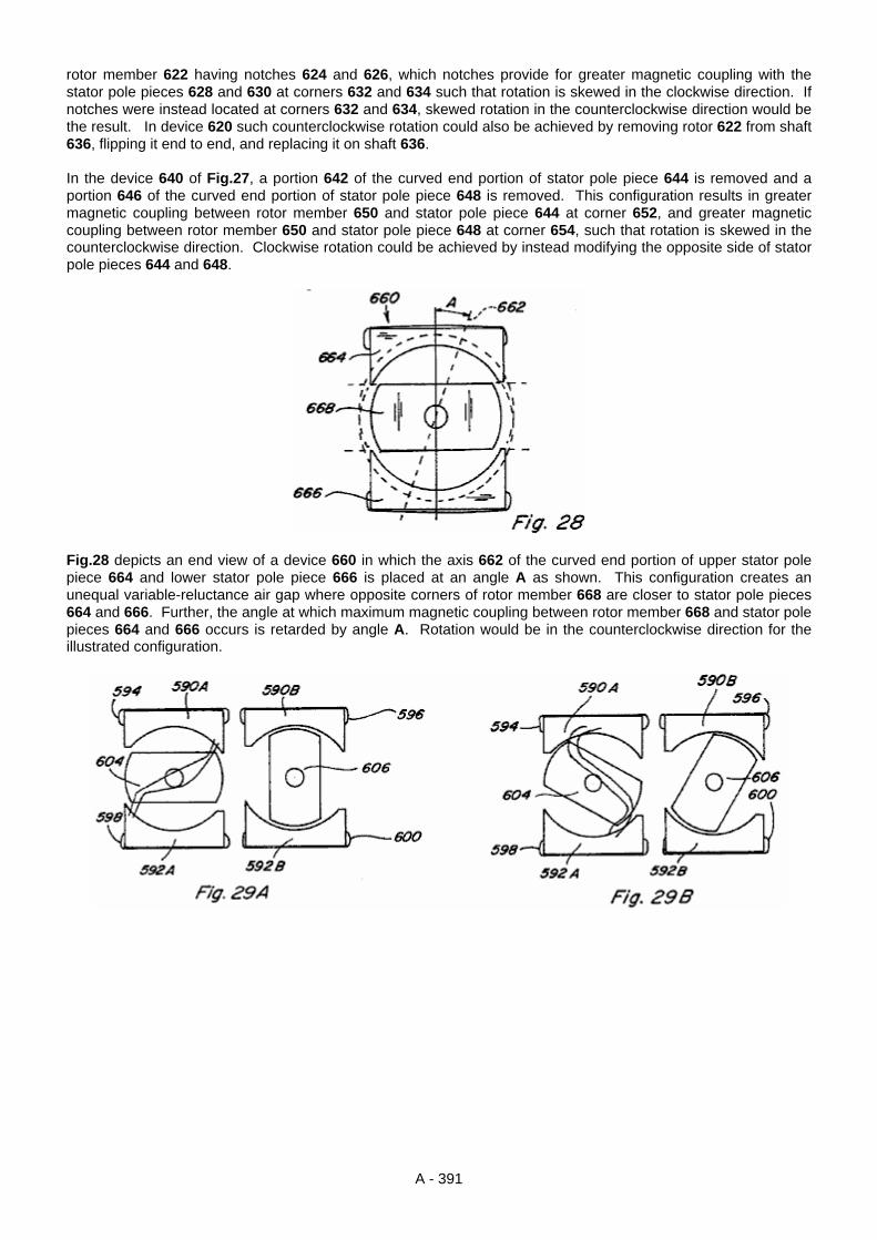
A - 391
rotor member 622 having notches 624 and 626, which notches provide for greater magnetic coupling with the stator pole pieces 628 and 630 at corners 632 and 634 such that rotation is skewed in the clockwise direction. If notches were instead located at corners 632 and 634, skewed rotation in the counterclockwise direction would be the result. In device 620 such counterclockwise rotation could also be achieved by removing rotor 622 from shaft 636, flipping it end to end, and replacing it on shaft 636. In the device 640 of Fig.27, a portion 642 of the curved end portion of stator pole piece 644 is removed and a portion 646 of the curved end portion of stator pole piece 648 is removed. This configuration results in greater magnetic coupling between rotor member 650 and stator pole piece 644 at corner 652, and greater magnetic coupling between rotor member 650 and stator pole piece 648 at corner 654, such that rotation is skewed in the counterclockwise direction. Clockwise rotation could be achieved by instead modifying the opposite side of stator pole pieces 644 and 648.
Fig.28 depicts an end view of a device 660 in which the axis 662 of the curved end portion of upper stator pole piece 664 and lower stator pole piece 666 is placed at an angle A as shown. This configuration creates an unequal variable-reluctance air gap where opposite corners of rotor member 668 are closer to stator pole pieces 664 and 666. Further, the angle at which maximum magnetic coupling between rotor member 668 and stator pole pieces 664 and 666 occurs is retarded by angle A. Rotation would be in the counterclockwise direction for the illustrated configuration.

A - 392
Referring again to motor 580 of Figs.23-25, rotary motion of such device is depicted in the end views of Figs.29A-29D. In each end view the end cap has been removed to show rotation of the rotor members and in each of Figs.29A-29D an end view depicting rotor member 604 and an end view depicting rotor member 606 are shown side-by-side. In Fig.29A, rotor member 604 is defined as being at zero degrees and rotor member 606 is defined as being at ninety degrees. Control coils 594, 598 are energised in a permanent magnet magnetic flux aiding manner such that no magnetic flux passes through stator pole piece path portions 590B and 592B. This allows rotor member 606 to move out of its ninety degree position and the magnetic coupling between rotor member 604 and stator pole piece path portions 590A and 592A will cause rotation to the position shown in Fig.29B and then Fig.29C. When rotor member 604 reaches the ninety degree position shown in Fig.29D control coils 594, 598 are de-energised and control coils 596, 600 are energised in a permanent magnet magnetic flux aiding manner causing rotation to continue due to the magnetic coupling between rotor member 606 and stator pole piece path portions 590B and 592B. Thus, by alternately energising the control coils of each path with every ninety degree rotation of rotor members 604 and 606, continuous rotary motion is achieved. The initial direction of rotation can be controlled by the circuit means used to energise control coils 594, 598 and 596, 600, which circuit means includes circuitry for detecting the angular position of the rotor members. In particular, if rotor members 604 and 606 are at rest in the position shown in Fig.29A, and coils 594, 598 are energised in an aiding manner, rotation may be clockwise or counterclockwise. If the desired direction is clockwise but upon energisation of coils 594, 598 the rotor members begin to move counterclockwise, the detection circuitry will immediately de-energise coils 594, 598 and energise coils 596, 600 so that the clockwise direction is achieved. Further, bypasses around permanent magnets 582 and 584 could be provided in rotary motion device 580, such as those shown in Fig.12, and rotor members 604 and 606 could be formed by permanent magnets so as to take advantage of energising the control coils in an exceeding manner.
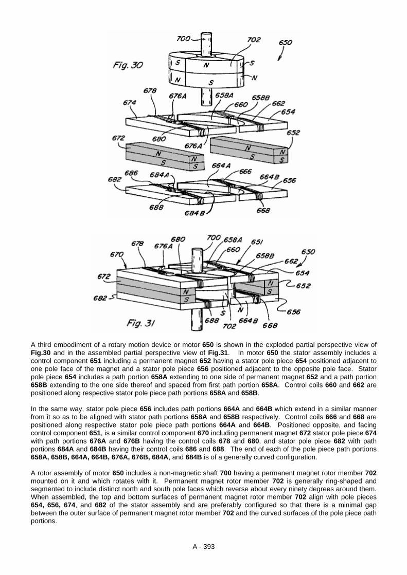
A - 393
A third embodiment of a rotary motion device or motor 650 is shown in the exploded partial perspective view of Fig.30 and in the assembled partial perspective view of Fig.31. In motor 650 the stator assembly includes a control component 651 including a permanent magnet 652 having a stator pole piece 654 positioned adjacent to one pole face of the magnet and a stator pole piece 656 positioned adjacent to the opposite pole face. Stator pole piece 654 includes a path portion 658A extending to one side of permanent magnet 652 and a path portion 658B extending to the one side thereof and spaced from first path portion 658A. Control coils 660 and 662 are positioned along respective stator pole piece path portions 658A and 658B. In the same way, stator pole piece 656 includes path portions 664A and 664B which extend in a similar manner from it so as to be aligned with stator path portions 658A and 658B respectively. Control coils 666 and 668 are positioned along respective stator pole piece path portions 664A and 664B. Positioned opposite, and facing control component 651, is a similar control component 670 including permanent magnet 672 stator pole piece 674 with path portions 676A and 676B having the control coils 678 and 680, and stator pole piece 682 with path portions 684A and 684B having their control coils 686 and 688. The end of each of the pole piece path portions 658A, 658B, 664A, 664B, 676A, 676B, 684A, and 684B is of a generally curved configuration. A rotor assembly of motor 650 includes a non-magnetic shaft 700 having a permanent magnet rotor member 702 mounted on it and which rotates with it. Permanent magnet rotor member 702 is generally ring-shaped and segmented to include distinct north and south pole faces which reverse about every ninety degrees around them. When assembled, the top and bottom surfaces of permanent magnet rotor member 702 align with pole pieces 654, 656, 674, and 682 of the stator assembly and are preferably configured so that there is a minimal gap between the outer surface of permanent magnet rotor member 702 and the curved surfaces of the pole piece path portions.

A - 394
Rotation of device 650 can be achieved by controlled, timed energising and de-energising of control coils 660, 662, 666, 668, 678, 680, 686, and 688. Exemplary rotation is demonstrated with reference to the top views of Figs.32A-32B which depict counterclockwise rotation of permanent magnet rotor member 702 through one-hundred and eighty degrees. In Fig.32A stator pole piece path portion 658A of component 651 is active and stator pole piece path portion 658B is not active, which may be achieved by energising control coil 660 in a permanent magnet magnetic flux aiding manner or by energising control coil 662 in a permanent magnet magnetic flux opposing manner. Stator pole piece path portion 676B of component 670 is active and stator pole piece path portion 676A is not active, which may be achieved by energising control coil 680 in a permanent magnet magnetic flux aiding manner or by energising control coil 678 in a permanent magnet magnetic flux opposing manner. Thus, portions 690 and 692 of permanent magnet rotor member 702, which both have a north magnetic polarity, will be repelled by the north polarity of stator pole piece path portions 658A and 676B aligned with it. Portions 694 and 696 of permanent magnet rotor member 702, both of which have a south magnetic polarity, will be attracted to the active path portions 658A and 676B. At the instant that rotor member portion 694 becomes aligned with stator pole piece path portion 658A, as shown in Fig.32B, all coils are de-energised such that all pole piece path portions will be active as shown. Pole piece path portions 658B and 676A are then kept active while pole piece path portions 658A and 676B are made inactive. This is achieved by energising control coils 662 and 678 in a permanent magnet magnetic flux aiding manner or by energising control coils 660 and 680 in a permanent magnet magnetic flux opposing manner. Rotor member portions 690 and 692 will again be repelled by the north polarity of path portions 658B and 676A aligned with it so that rotation of permanent magnet rotor 702 is continued.
In Fig.32D all coils are shown de-energised when rotor portion 692 aligns with pole piece path portion 658A. By continuing this timed sequence of energisation and de-energisation of the control coils, continued rotary movement is achieved. As explained above, the initial direction of rotation can be controlled by circuit means
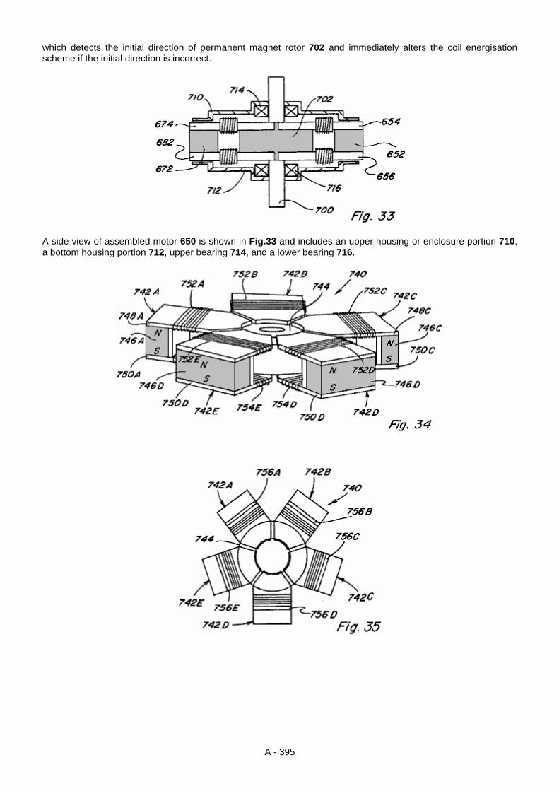
A - 395
which detects the initial direction of permanent magnet rotor 702 and immediately alters the coil energisation scheme if the initial direction is incorrect.
A side view of assembled motor 650 is shown in Fig.33 and includes an upper housing or enclosure portion 710, a bottom housing portion 712, upper bearing 714, and a lower bearing 716.
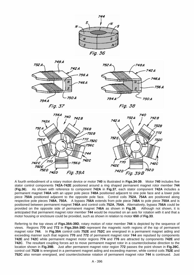
A - 396
A fourth embodiment of a rotary motion device or motor 740 is illustrated in Figs.34-39. Motor 740 includes five stator control components 742A-742E positioned around a ring shaped permanent magnet rotor member 744 (Fig.36). As shown with reference to component 742A in Fig.37, each stator component 742A includes a permanent magnet 746A with an upper pole piece 748A positioned adjacent to one pole face and a lower pole piece 750A positioned adjacent to the opposite pole face. Control coils 752A, 754A are positioned along respective pole pieces 748A, 750A. A bypass 756A extends from pole piece 748A to pole piece 750A and is positioned between permanent magnet 746A and control coils 752A, 754A. Alternatively, bypass 756A could be provided on the opposite side of permanent magnet 746A as shown in Fig.38. Although not shown, it is anticipated that permanent magnet rotor member 744 would be mounted on an axis for rotation with it and that a motor housing or enclosure could be provided, such as shown in relation to motor 650 of Fig.33. Referring to the top views of Figs.39A-39D, rotary motion of rotor member 744 is depicted by the sequence of views. Regions 770 and 772 in Figs.39A-39D represent the magnetic north regions of the top of permanent magnet rotor 744. In Fig.39A control coils 752E and 752C are energised in a permanent magnet aiding and exceeding manner such that regions 770 and 772 of permanent magnet rotor 744 are repulsed by components 742E and 742C while permanent magnet motor regions 774 and 776 are attracted by components 742E and 742C. The resultant coupling forces act to move permanent magnet rotor in a counterclockwise direction to the location shown in Fig.39B. Just after permanent magnet rotor region 772 passes the point shown in Fig.39C, control coil 752B is energised in a permanent magnet aiding and exceeding manner, while control coils 752E and 752C also remain energised, and counterclockwise rotation of permanent magnet rotor 744 is continued. Just
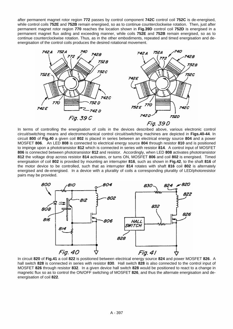
A - 397
after permanent magnet rotor region 772 passes by control component 742C control coil 752C is de-energised, while control coils 752E and 752B remain energised, so as to continue counterclockwise rotation. Then, just after permanent magnet rotor region 770 reaches the location shown in Fig.39D control coil 752D is energised in a permanent magnet flux aiding and exceeding manner, while coils 752E and 752B remain energised, so as to continue counterclockwise rotation. Thus, as in the other embodiments, repeated and timed energisation and de-energisation of the control coils produces the desired rotational movement.
In terms of controlling the energisation of coils in the devices described above, various electronic control circuit/switching means and electromechanical control circuit/switching machines are depicted in Figs.40-44. In circuit 800 of Fig.40 a given coil 802 is placed in series between an electrical energy source 804 and a power MOSFET 806. An LED 808 is connected to electrical energy source 804 through resistor 810 and is positioned to impinge upon a phototransistor 812 which is connected in series with resistor 814. A control input of MOSFET 806 is connected between phototransistor 812 and resistor. Accordingly, when LED 808 activates phototransistor 812 the voltage drop across resistor 814 activates, or turns ON, MOSFET 806 and coil 802 is energised. Timed energisation of coil 802 is provided by mounting an interrupter 816, such as shown in Fig.42, to the shaft 816 of the motor device to be controlled, such that as interrupter 814 rotates with shaft 816 coil 802 is alternately energised and de-energised. In a device with a plurality of coils a corresponding plurality of LED/photoresistor pairs may be provided.
In circuit 820 of Fig.41 a coil 822 is positioned between electrical energy source 824 and power MOSFET 826. A hall switch 828 is connected in series with resistor 830. Hall switch 828 is also connected to the control input of MOSFET 826 through resistor 832. In a given device hall switch 828 would be positioned to react to a change in magnetic flux so as to control the ON/OFF switching of MOSFET 826, and thus the alternate energisation and de-energisation of coil 822.
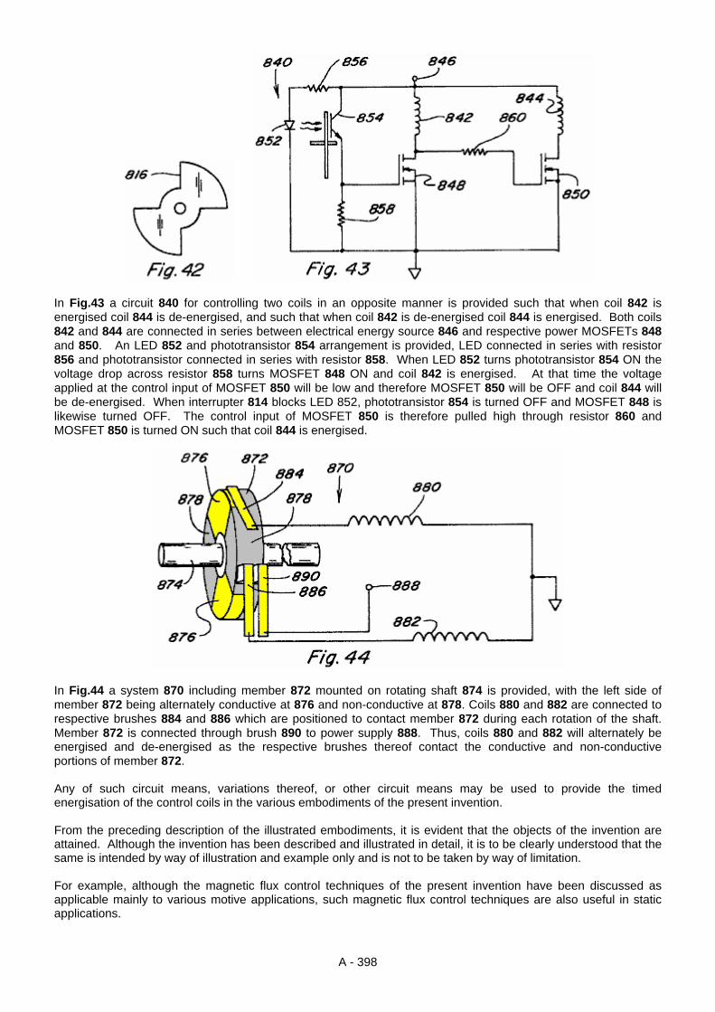
A - 398
In Fig.43 a circuit 840 for controlling two coils in an opposite manner is provided such that when coil 842 is energised coil 844 is de-energised, and such that when coil 842 is de-energised coil 844 is energised. Both coils 842 and 844 are connected in series between electrical energy source 846 and respective power MOSFETs 848 and 850. An LED 852 and phototransistor 854 arrangement is provided, LED connected in series with resistor 856 and phototransistor connected in series with resistor 858. When LED 852 turns phototransistor 854 ON the voltage drop across resistor 858 turns MOSFET 848 ON and coil 842 is energised. At that time the voltage applied at the control input of MOSFET 850 will be low and therefore MOSFET 850 will be OFF and coil 844 will be de-energised. When interrupter 814 blocks LED 852, phototransistor 854 is turned OFF and MOSFET 848 is likewise turned OFF. The control input of MOSFET 850 is therefore pulled high through resistor 860 and MOSFET 850 is turned ON such that coil 844 is energised.
In Fig.44 a system 870 including member 872 mounted on rotating shaft 874 is provided, with the left side of member 872 being alternately conductive at 876 and non-conductive at 878. Coils 880 and 882 are connected to respective brushes 884 and 886 which are positioned to contact member 872 during each rotation of the shaft. Member 872 is connected through brush 890 to power supply 888. Thus, coils 880 and 882 will alternately be energised and de-energised as the respective brushes thereof contact the conductive and non-conductive portions of member 872. Any of such circuit means, variations thereof, or other circuit means may be used to provide the timed energisation of the control coils in the various embodiments of the present invention. From the preceding description of the illustrated embodiments, it is evident that the objects of the invention are attained. Although the invention has been described and illustrated in detail, it is to be clearly understood that the same is intended by way of illustration and example only and is not to be taken by way of limitation. For example, although the magnetic flux control techniques of the present invention have been discussed as applicable mainly to various motive applications, such magnetic flux control techniques are also useful in static applications.
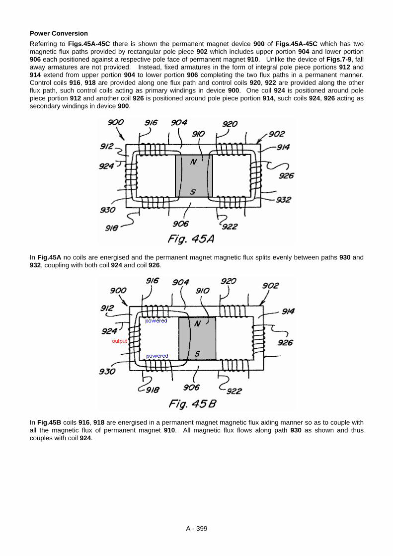
A - 399
Power Conversion Referring to Figs.45A-45C there is shown the permanent magnet device 900 of Figs.45A-45C which has two magnetic flux paths provided by rectangular pole piece 902 which includes upper portion 904 and lower portion 906 each positioned against a respective pole face of permanent magnet 910. Unlike the device of Figs.7-9, fall away armatures are not provided. Instead, fixed armatures in the form of integral pole piece portions 912 and 914 extend from upper portion 904 to lower portion 906 completing the two flux paths in a permanent manner. Control coils 916, 918 are provided along one flux path and control coils 920, 922 are provided along the other flux path, such control coils acting as primary windings in device 900. One coil 924 is positioned around pole piece portion 912 and another coil 926 is positioned around pole piece portion 914, such coils 924, 926 acting as secondary windings in device 900.
In Fig.45A no coils are energised and the permanent magnet magnetic flux splits evenly between paths 930 and 932, coupling with both coil 924 and coil 926.
In Fig.45B coils 916, 918 are energised in a permanent magnet magnetic flux aiding manner so as to couple with all the magnetic flux of permanent magnet 910. All magnetic flux flows along path 930 as shown and thus couples with coil 924.
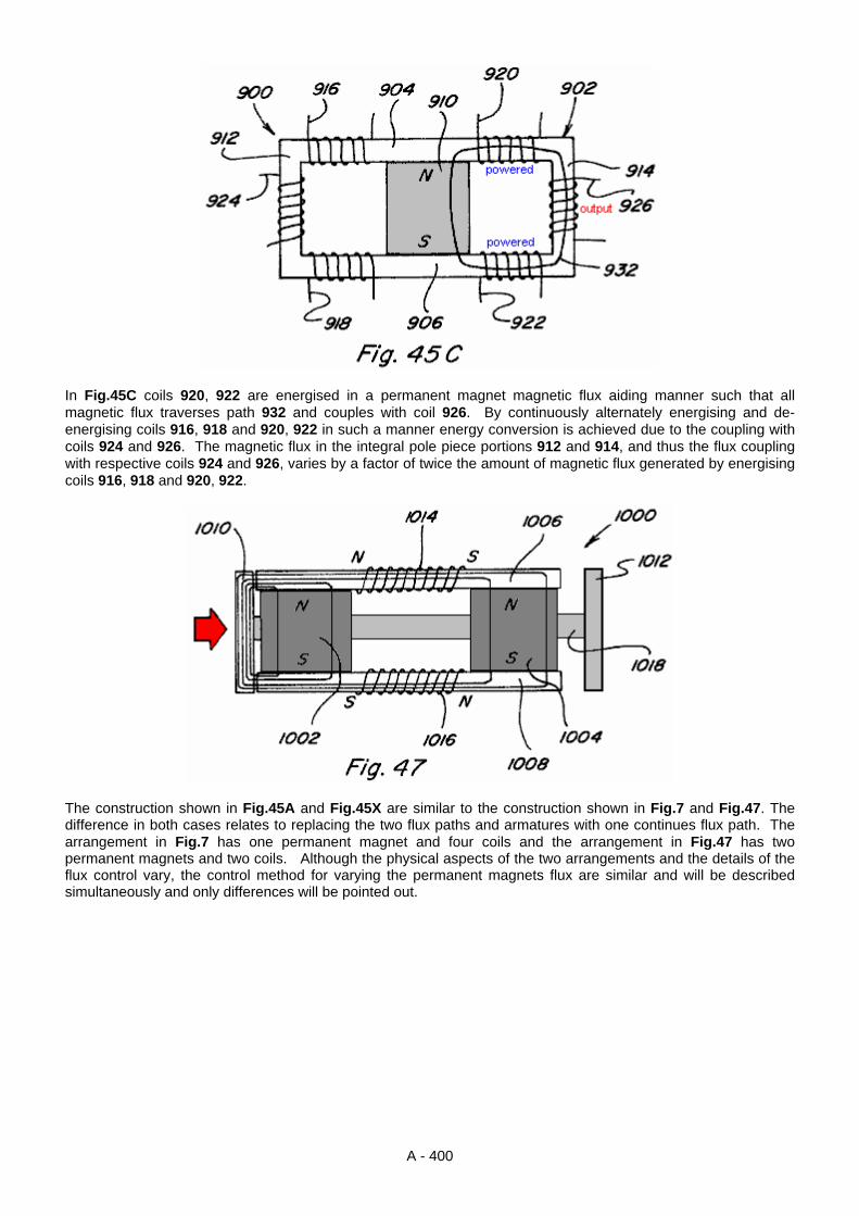
A - 400
In Fig.45C coils 920, 922 are energised in a permanent magnet magnetic flux aiding manner such that all magnetic flux traverses path 932 and couples with coil 926. By continuously alternately energising and de-energising coils 916, 918 and 920, 922 in such a manner energy conversion is achieved due to the coupling with coils 924 and 926. The magnetic flux in the integral pole piece portions 912 and 914, and thus the flux coupling with respective coils 924 and 926, varies by a factor of twice the amount of magnetic flux generated by energising coils 916, 918 and 920, 922.
The construction shown in Fig.45A and Fig.45X are similar to the construction shown in Fig.7 and Fig.47. The difference in both cases relates to replacing the two flux paths and armatures with one continues flux path. The arrangement in Fig.7 has one permanent magnet and four coils and the arrangement in Fig.47 has two permanent magnets and two coils. Although the physical aspects of the two arrangements and the details of the flux control vary, the control method for varying the permanent magnets flux are similar and will be described simultaneously and only differences will be pointed out.
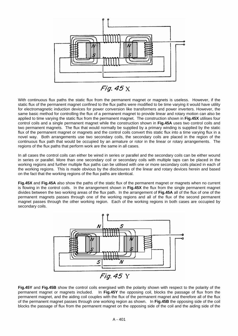
A - 401
With continuous flux paths the static flux from the permanent magnet or magnets is useless. However, if the static flux of the permanent magnet confined to the flux paths were modified to be time varying it would have utility for electromagnetic induction devices for power conversion like transformers and power inverters. However, the same basic method for controlling the flux of a permanent magnet to provide linear and rotary motion can also be applied to time varying the static flux from the permanent magnet. The construction shown in Fig.45X utilises four control coils and a single permanent magnet while the construction shown in Fig.45A uses two control coils and two permanent magnets. The flux that would normally be supplied by a primary winding is supplied by the static flux of the permanent magnet or magnets and the control coils convert this static flux into a time varying flux in a novel way. Both arrangements use two secondary coils, the secondary coils are placed in the region of the continuous flux path that would be occupied by an armature or rotor in the linear or rotary arrangements. The regions of the flux paths that perform work are the same in all cases. In all cases the control coils can either be wired in series or parallel and the secondary coils can be either wound in series or parallel. More than one secondary coil or secondary coils with multiple taps can be placed in the working regions and further multiple flux paths can be utilised with one or more secondary coils placed in each of the working regions. This is made obvious by the disclosures of the linear and rotary devices herein and based on the fact that the working regions of the flux paths are identical. Fig.45X and Fig.45A also show the paths of the static flux of the permanent magnet or magnets when no current is flowing in the control coils. In the arrangement shown in Fig.45X the flux from the single permanent magnet divides between the two working areas of the flux path. In the arrangement of Fig.45A all of the flux of one of the permanent magnets passes through one of the working regions and all of the flux of the second permanent magnet passes through the other working region. Each of the working regions in both cases are occupied by secondary coils.
Fig.45Y and Fig.45B show the control coils energised with the polarity shown with respect to the polarity of the permanent magnet or magnets included. In Fig.45Y the opposing coil, blocks the passage of flux from the permanent magnet, and the aiding coil couples with the flux of the permanent magnet and therefore all of the flux of the permanent magnet passes through one working region as shown. In Fig.45B the opposing side of the coil blocks the passage of flux from the permanent magnet on the opposing side of the coil and the aiding side of the

A - 402
coil couples with the flux of the other permanent magnet and therefore all of the flux of both the permanent magnets passes through the working region as shown.
Fig.45Z and Fig.45C show the control coils energised with a polarity opposite of that shown in Fig.45Y and Fig.45B. The same action occurs and results in all of the permanent magnet or magnets path flux passing through the opposite working regions. By alternating the polarity of the control coils during one cycle, one working region experiences an increasing flux and the opposite region experiences a decreasing flux and during the next cycle the opposite occurs. This results in the induction of a voltage in the secondary coils that is decided by the magnitude of the change in flux in the working region and the time in which this change occurs. The novelty of this discovery is that the primary flux inducing the voltage in the secondary coils is supplied by the permanent magnet or magnets and is far greater than the flux supplied by the control coils.
Further, in the rotary motion devices of Fig.31 and Fig.34, it is not necessary that respective rotor members 702 and 744 be formed of permanent magnets. Each could take the form shown in Fig.46 where sections 950 and 952 are formed of magnetic material such as soft iron and sections 954 and 956 are formed by a non-magnetic filler material.

A - 403
Fig.47 and Fig.48 show another embodiment 1000 of the subject device. The embodiment 1000 includes two spaced permanent magnets 1002 and 1004 each of which has its north pole adjacent to the upper surface and its south pole adjacent to the lower surface. A magnetisable bridging member 1006 extends across and makes contact with the north magnetic poles of the magnets 1002 and 1004 and another magnetisable bridging member 1008 makes contact with the south magnetic poles of the two permanent magnets 1002 and 1004. The members 1006 and 1008 extend slightly beyond the opposite sides of the respective permanent magnets 1002 and 1004 and a pair of spaced armature members 1010 and 1012 are positioned to move into and out of engagement with the ends of the members 1006 and 1008. Coils 1014 and 1016 are mounted respectively on the members 1006 and 1008 in the space between the permanent magnets 1002 and 1004, and the armatures 1010 and 1012 are shown connected together by a rod 1018 which enables them to move backwards and forwards into engagement with the respective members 1006 and 1008 when different voltages are applied to the respective coils 1014 and 1016. In Fig.47, the coils 1014 and 1016 are energised as shown with the coil 1014 having its north magnetic end to the left and its south magnetic end to the right and the opposite is true of the coil 1016. In Fig.48, the voltage applied to the respective coils 1014 and 1016 is reversed so that the polarity of the left end of coil 1014 is south and the polarity of the opposite end of the same coil 1014 is a north magnetic pole. The reverse is true of the coil 1016. In Fig.47 and Fig.48 it should be noted that the relationship of aiding and opposing is indicated on the figures to indicate the relationship when the coils are energised. For example, in Fig.47 when the coils are energised as shown the relationship is opposing for the permanent magnet 1002 and is aiding with respect to the permanent magnet 1004. The reverse is true when the voltage on the coils is reversed as shown in Fig.48. The movement of the armature is therefore controlled by the proper timing of the voltage on these coils. The same principles can be applied to produce rotating movement as shown in Fig.42.
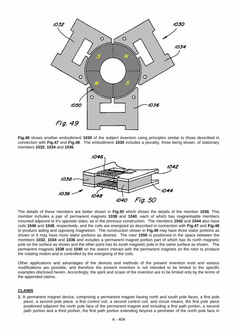
A - 404
Fig.49 shows another embodiment 1030 of the subject invention using principles similar to those described in connection with Fig.47 and Fig.48. The embodiment 1030 includes a plurality, three being shown, of stationary members 1032, 1034 and 1036.
The details of these members are better shown in Fig.50 which shows the details of the member 1036. This member includes a pair of permanent magnets 1038 and 1040, each of which has magnetisable members mounted adjacent to it’s opposite sides, as in the previous construction. The members 1042 and 1044 also have coils 1046 and 1048, respectively, and the coils are energised as described in connection with Fig.47 and Fig.48 to produce aiding and opposing magnetism. The construction shown in Fig.49 may have three stator portions as shown or it may have more stator portions as desired. The rotor 1050 is positioned in the space between the members 1032, 1034 and 1036 and includes a permanent magnet portion part of which has its north magnetic pole on the surface as shown and the other parts has its south magnetic pole in the same surface as shown. The permanent magnets 1038 and 1040 on the stators interact with the permanent magnets on the rotor to produce the rotating motion and is controlled by the energising of the coils. Other applications and advantages of the devices and methods of the present invention exist and various modifications are possible, and therefore the present invention is not intended to be limited to the specific examples disclosed herein. Accordingly, the spirit and scope of the invention are to be limited only by the terms of the appended claims. CLAIMS 1. A permanent magnet device, comprising a permanent magnet having north and south pole faces, a first pole
piece, a second pole piece, a first control coil, a second control coil, and circuit means, the first pole piece positioned adjacent the north pole face of the permanent magnet and including a first path portion, a second path portion and a third portion, the first path portion extending beyond a perimeter of the north pole face in

A - 405
one direction and the second path portion extending beyond the perimeter of the north pole face in another direction to define first and second flux paths for magnetic flux emanating from the north pole face of the permanent magnet, the first path portion of the first pole piece connected to the second path portion of the first pole piece by the third portion which extends across the north pole face of the permanent magnet, the second pole piece positioned adjacent the south pole face and including a first path portion and a second path portion, the first path portion extending beyond a perimeter of the south pole face and substantially aligned with the first path portion of the first pole piece, the second path portion extending beyond the perimeter of the south pole face and substantially aligned with the second path portion of the first pole piece, the first control coil positioned around the first path portion of the first pole piece, the second control coil positioned around the second path portion of the first pole piece, the circuit means connected to each of the first control coil and the second control coil to alternately energise the first coil and the second coil in a timed sequential manner.
2. The permanent magnet device as set forth in claim 1, wherein the first control coil and the second control coil
are alternately energised in a permanent magnet magnetic flux aiding manner. 3. The permanent magnet device as set forth in claim 1, wherein the first control coil and the second control coil
are alternately energised in a permanent magnet magnetic flux opposing manner. 4. The permanent magnet device as set forth in claim 1, further comprising a rotor member mounted on a shaft for
rotation therewith, the rotor member sized, shaped, and positioned to extend substantially from the first path portion of the first pole piece to the first path portion of the second pole piece during at least some part of its rotation.
5. The permanent magnet device as set forth in claim 4, wherein the rotor member is formed by at least one
permanent magnet. 6. The permanent magnet device as set forth in claim 1, wherein the second path portion of the first pole piece
and the second path portion of the second pole piece are positioned alongside the first path portion of the first pole piece and the first path portion of the first pole piece.
7. The permanent magnet device as set forth in claim 1, further comprising a first bypass extending from the first
path portion of the first pole piece to the first path portion of the second pole piece, one end of the first bypass positioned adjacent the first path portion of the first pole piece and between the permanent magnet and the first control coil.
8. The permanent magnet device as set forth in claim 6, further comprising a second bypass extending from the
second path portion of the first pole piece to the second path portion of the second pole piece, one end of the second bypass positioned adjacent the second path portion of the first pole piece and between the permanent magnet and the second control coil.
9. The permanent magnet device as set forth in claim 1, further comprising a plurality of armatures arranged to
define a path of movement, wherein the second path portion of the first pole piece and the second path portion of the second pole piece are positioned alongside the first path portion of the first pole piece and the first path portion of the second pole piece, and wherein all of such pole piece path portions include an end face positioned adjacent the path of movement defined by the plurality of armatures.
10. The permanent magnet device as set forth in claim 1, wherein the first control coil and the second control coil
are simultaneously energised one in a permanent magnet magnetic flux aiding manner and one in a permanent magnet magnetic flux opposing manner.
11. The permanent magnet device as set forth in claim 1, further comprising two shaft connected armatures which
can be positioned adjacent the ends of the first and second pole pieces, wherein each of the armatures is formed by a permanent magnet.
12. The permanent magnet device of claim 1 further comprising a first fixed armature extending between the first
path portion of the first pole piece to the first path portion of the second pole piece and a second fixed armature extending between the second path portion on the first pole piece to the second path portion of the second pole piece.
13. The permanent magnet device of claim 12 where a first secondary coil is wrapped around the first fixed
armature and a second secondary coil is wrapped around the second fixed armature. 14. The permanent magnet device of claim 13 including circuit means connected to the control coils to control the
energising thereof to produce a varying flux in the armatures and to induce voltage in the secondary coils.

A - 406
15. The permanent magnet device of claim 1 wherein there are at least two permanent magnets each having
north and south pole faces, the first pole piece being positioned extending between the north pole faces of the permanent magnets and the second pole piece positioned extending between adjacent south pole faces of the permanent magnets.
16. A method for controlling the path of magnetic flux from a permanent magnet, the method comprising the steps
of:
(a) placing a first pole piece adjacent a first pole face of the permanent magnet so as to have at least first and second path portions extending beyond a perimeter of the first pole face;
(b) placing a second pole piece adjacent a second pole face of the permanent magnet so as to include at least
one portion which substantially aligns with the first and second path portions of the first pole piece; (c) placing a first control coil along and around the first path portion of the first pole piece; (d) placing a second control coil along and around the second path portion of the first pole piece; (e) repeatedly energising the first control coil in a permanent magnet magnetic flux opposing manner so as to
prevent magnetic flux of the permanent magnet from traversing the first path portion of the first pole piece; and
(f) repeatedly energising the second control coil in a permanent magnet magnetic flux opposing manner so as
to prevent magnetic flux of the permanent magnet from traversing the second path portion of the first pole piece.
17. The method as set forth in claim 16 wherein the energisation of steps (e) and (t) take place in a simultaneous
manner. 18. A method for controlling the path of magnetic flux from a permanent magnet, the method comprising the steps
of:
(a) placing a first pole piece adjacent a first pole face of the permanent magnet so as to have at least first and second path portions extending beyond a perimeter of the first pole face;
(b) placing a second pole piece adjacent a second pole face of the permanent magnet so as to include at least
one portion which substantially aligns with the first and second path portions of the first pole piece; (c) placing a first control coil along and around the first path portion of the first pole piece; (d) placing a second control coil along and around the second path portion of the first pole piece; and (e) alternately performing the following steps in a repeated manner:
(i) energising the first control coil in a permanent magnet magnetic flux aiding manner so as to couple with
substantially all magnetic flux of the permanent magnet such that substantially no magnetic flux of the permanent magnet traverses the second path portion of the first pole piece when the first control coil is so energised; and
(ii) energising the second control coil in a permanent magnet magnetic flux opposing manner so as to
couple with substantially all magnetic flux of the permanent magnet such that substantially no magnetic flux of the permanent magnet traverses the first path portion of the first pole piece when the second control coil is so energised.
19. A method for controlling the path of magnetic flux from a permanent magnet the method comprising the steps
of:
(a) placing a first pole piece adjacent a first pole face of the permanent magnet so as to have at least first and second path portions extending beyond a perimeter of the first pole face;
(b) placing a second pole piece adjacent a second pole face of the permanent magnet so as to include at least
one portion which substantially aligns with the first and second path portions of the first pole piece;

A - 407
(c) placing a first control coil along and around the first path portion of the first pole piece; (d) placing a second control coil along and around the second path portion of the first pole piece; and (e) alternately performing the following steps in a repeated manner:
(i) simultaneously energising the first control coil in a permanent magnet magnetic flux aiding manner and
the second control coil in a permanent magnet flux opposing manner; and (ii) simultaneously energising the first control coil in a permanent magnet flux opposing manner and the
second control coil in a permanent magnet magnetic flux aiding manner. 20. A rotary motion device, comprising a rotor assembly including a shaft which defines an axis of rotation of the
assembly, a rotor pole piece mounted for rotation with the shaft, the rotor pole piece including an outer ring portion having at least two path portions extending inwardly from a periphery of the outer ring portion;
a stator assembly including a permanent magnet having a generally ring-shaped configuration, a first pole face of the permanent magnet positioned adjacent the outer ring portion of the rotor pole piece, the stator assembly further comprising a stator pole piece including an outer ring portion positioned adjacent a second pole face of the permanent magnet and having a plurality of path portions extending inwardly from the periphery, each path portion further including a respective portion which extends toward a plane defined by the first pole face of the permanent magnet and capable of being aligned with each of the rotor pole piece path portions at certain rotational positions of the rotor pole piece, each path portion including a control coil positioned along it; and circuit means connected to each of the coils and including a source of electrical energy and switch means for energising respective ones of the control coils in a predetermined timed sequence based upon rotation of the rotor assembly.
21. A rotary motion device, comprising:
a rotor assembly including a shaft which defines an axis of rotation of the assembly, a pair of spaced elongated rotor members mounted on the shaft at spaced locations thereon and angularity oriented with respect to each other, each of the elongated rotor members formed of a magnetic material; a stator assembly including a permanent magnet having opposed first and second pole faces, a first pole piece positioned adjacent the first pole face and a second pole piece positioned adjacent the second pole face, each pole piece including a respective first path portion extending beyond a perimeter of its adjacent pole face and having an curved shaped end portion, the first path portion of the first pole piece aligned with the first path portion of the second pole piece, each pole piece further including a respective second path portion extending beyond the perimeter of its adjacent pole face in a direction opposite to that of the first path portions and having an curved shaped end portion, the second path portion of the first pole piece aligned with the second path portion of the second pole piece, at least one of the first path portions of the first pole piece and the first path portion of the second pole piece including a control coil mounted on at least one of the pole pieces, at least one of the second path portions of the first pole piece and the second path portion of the second pole piece including a control coil mounted on at least one of the pole pieces, wherein the rotor assembly extends from end to end of the stator assembly such that the elongate members are aligned with the curved shaped end portions of the path portions of the pole pieces; and circuit means connected to each of the coils and including a source of electrical energy and switch means for energising respective ones of the control coils in a predetermined timed sequence based upon rotation of the rotor assembly.
22. A rotary motion device comprising:
a rotor assembly including a shaft which defines an axis of rotation of the assembly, a ring-shaped rotor member mounted for rotation with the shaft, the ring-shaped rotor member including a plurality of distinct circumferential regions; a stator assembly including a first permanent magnet, a first pole piece positioned against a first pole face and a second pole piece positioned against a second pole face, the first pole piece including at least a first path portion extending beyond a perimeter of the first pole face, the second pole piece including at least a first path portion extending beyond a perimeter of the second pole face, the first path portion of the first pole piece aligned with the first path portion of the second pole piece, at least a portion of the ring-shaped rotor member

A - 408
positioned between the first path portion of the first pole piece and the first path portion of the second pole piece, at least one of the first path portions of the first pole piece and the first path portion of the second pole piece including a first control coil positioned at a point intermediate the first permanent magnet and the ring-shaped rotor member; and circuit means connected to the first control coil and including a source of electrical energy and switch means for energising the first control coil in a predetermined timed manner based upon rotation of the rotor assembly.
23. The rotary motion device as set forth in claim 22, wherein the ring-shaped rotor member is formed by a
permanent magnet having distinct circumferential regions of opposite polarity. 24. The rotary motion device as set forth in claim 23, wherein the first pole piece includes a second path portion
spaced from and extending adjacent to the first path portion, the second pole piece including a second path portion spaced from and extending adjacent to the first path portion such that the second path portion of the first pole piece is aligned with the second path portion of the second pole piece, at least a portion of the ring-shaped permanent magnet rotor member positioned between the second path portion of the first pole piece and the second path portion of the second pole piece, at least one of the second path portions of the first pole piece and the second path portion of the second pole piece having a second control coil mounted on at least one of the pole pieces at a point intermediate the first permanent magnet and the ring-shaped permanent magnet rotor member, the second control coil connected to the circuit means so as to be energised in a predetermined timed manner based upon rotation of the rotor assembly.
25. The rotary motion device as set forth in claim 22, wherein the stator assembly further comprises a second
permanent magnet, a third pole piece positioned adjacent a first pole face of the second permanent magnet and a fourth pole piece positioned adjacent a second pole face of the second permanent magnet, the third pole piece including at least a first path portion extending beyond a perimeter of the second permanent magnet first pole face, the fourth pole piece including at least a first path portion extending beyond a perimeter of the second permanent magnet second pole face, the first path portion of the third pole face aligned with the first path portion of the fourth pole piece, at least a portion of the ring-shaped permanent magnet rotor member positioned between the first path portion of the third pole piece and the first path portion of the fourth pole piece, at least one of the first path portions of the third pole piece and the first path portion of the fourth pole piece including a third control coil mounted on at least one of the pole pieces at a point intermediate the second permanent magnet and the ring-shaped permanent magnet rotor member, the third pole piece including a second path portion spaced from and extending adjacent to the first path portion the fourth pole piece including a second path portion spaced from and extending adjacent to the first path portion thereof such that the second path portion of the third pole piece is aligned with the second path portion of the fourth pole piece, at least a portion of the ring-shaped permanent magnet rotor member positioned between the second path portion of the third pole piece and the second path portion of the fourth pole piece, at least one of the second path portions of the third pole piece and the second path portion of the fourth pole piece including a fourth control coil mounted on at least one of the pole pieces at a point intermediate the second permanent magnet and the ring-shaped permanent magnet rotor member, wherein each of the third and fourth control coils are connected to the circuit means so as to be energised in a predetermined timed manner based upon rotation of the rotor assembly.
26. A device for producing rotary motion comprising:
a rotor assembly including a shaft which defines an axis of rotation for the assembly, a ring-shaped rotor member mounted for rotation with the shaft, the ring-shaped rotor member having a plurality of distinct circumferentially positioned regions extending around the axis, a stator assembly including a first permanent magnet, a first pole piece positioned against the first pole face of the first pole piece and a second pole piece positioned against a second pole face of the first pole piece, the first pole piece including at least a first path portion extending beyond a perimeter of the first pole face, the second pole piece including at least a first path portion extending beyond the perimeter of the second pole face, the first path portion of the first pole piece aligned with the first path portion of the second pole piece, at least a portion of the ring-shaped rotor member positioned between the first path portion of the first pole piece and the first path portion of the second pole piece, at least one of the first path portions of the first pole piece and the first path portion of the second pole piece including a first control coil mounted on at least one of the pole pieces at a point intermediate the first permanent magnet and the ring-shaped rotor member; and circuit means connected to the first control coil and including a source of electrical energy and switch means for energising the first control coil in a predetermined timed manner based upon position of the rotor assembly during rotation of the rotor assembly.
27. The device for producing rotary motion of claim 26 wherein the circuit means includes means for timing the
energising of the first control coil includes means for adjusting the timing thereof.

A - 409
28. The device for producing rotor motion of claim 26 including means to vary the flux generated in the first and
second pole pieces. 29. A device for handling the flux between two separate permanent magnets each of which has a north magnetic
pole adjacent one side face and the south magnetic pole adjacent to the opposite side face, the north and south side pole faces respectively of both magnets being substantially in alignment, a first member in surface-to-surface contact with the north magnetic faces of the spaced permanent magnets, a second member in surface-to-surface contact with the south magnetic faces of the spaced permanent magnets, first and second armatures each positioned adjacent opposite ends of the first and second permanent magnets and adjacent to opposite ends of the spaced members, a coil mounted on each of the members in the space between the adjacent permanent magnets, and means for applying voltages of predetermined polarities across the respective coils to change the magnetic coupling between the permanent magnets and between the armatures.
30. A device for producing rotational movement comprising:
a rotor having a shaft rotatable about the axis thereof, a member constructed of permanent magnets mounted on the shaft, said member having circumferential portions some of which have a north magnetic pole and others a south magnetic pole adjacent to the same side thereof, the opposite surface of the permanent magnet member having north magnetic poles opposite the south magnetic poles and south magnetic poles opposite the north magnetic poles, a stator having a plurality of circumferentially spaced portions each of which includes at least one permanent magnet and a pair of members mounted adjacent opposite sides of the permanent magnets, the members being positioned adjacent to the periphery of the rotor permanent magnet member and means on the member adjacent each opposite side of the stator permanent magnet for mounting a coil, and means for energising the coil on each stator portion in sequence to produce magnetic coupling force between the stator and the rotor in a direction to produce rotating motion of the rotor.
31. A device including a rotating member and a stationary member, each having a permanent magnet portion
positioned to produce magnetic coupling force between them in predetermined positions thereof, the rotor including a shaft rotatable about its axis and the permanent magnet extending around the shaft and formed by a plurality of adjacent portions of permanent magnet material whereby adjacent portions have their north and south magnetic pole faces on opposite sides of the rotor permanent magnet, a plurality of stator members each stator member having at least one permanent magnet having a north magnetic pole adjacent one side and a south magnetic pole adjacent to the opposite side, a pair of members positioned adjacent respective opposite sides of the stator permanent magnet in position to extend to adjacent the rotor permanent magnet whereby a flux path is formed between the members and the stator and rotor permanent magnets, a coil mounted on each member of the stator and means for applying a voltage of predetermined polarity to each of said coils to control the flux through a path between the permanent magnets and to control the coupling force between the permanent magnets on the stator and the permanent magnets on the rotor.
32. A motion producing device comprising at least one permanent magnet having a north pole opposite and
spaced from a south pole, a pair of spaced substantially parallel members adjacent respectively the north and south poles of the at least one permanent magnet and extending outwardly to substantially aligned opposite edges, a flux supporting member positioned adjacent the respective opposite edges of each pair of parallel members, a coil on selected ones of the parallel members, and a source of electrical energy connected to each of the coils for energising the coils to change the flux in the parallel members and in the flux supporting members.
33. The motion producing device of claim 32 wherein there are at least two spaced permanent magnets extending
between the parallel members. 34. The motion producing device of claim 32 wherein one of said pair of parallel members is subdivided into a
plurality of sidewardly extending portions extending to one of said opposite side edges, at least one of said coils being positioned on at least one of said sidewardly extending portions.
35. The motion producing device of claim 34 wherein there are coils on a plurality of respective ones of the
sidewardly extending portions. 36. The motion producing device of claim 32 wherein the permanent magnet and the parallel members are
annular in shape. 37. The motion producing device of claim 32 including a by-pass member extending between the pair of spaced
substantial parallel members adjacent one side of the permanent magnet.
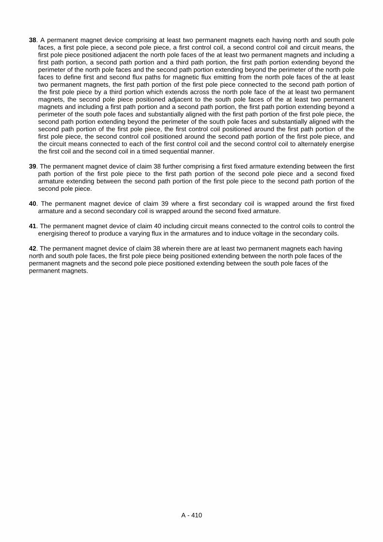
A - 410
38. A permanent magnet device comprising at least two permanent magnets each having north and south pole
faces, a first pole piece, a second pole piece, a first control coil, a second control coil and circuit means, the first pole piece positioned adjacent the north pole faces of the at least two permanent magnets and including a first path portion, a second path portion and a third path portion, the first path portion extending beyond the perimeter of the north pole faces and the second path portion extending beyond the perimeter of the north pole faces to define first and second flux paths for magnetic flux emitting from the north pole faces of the at least two permanent magnets, the first path portion of the first pole piece connected to the second path portion of the first pole piece by a third portion which extends across the north pole face of the at least two permanent magnets, the second pole piece positioned adjacent to the south pole faces of the at least two permanent magnets and including a first path portion and a second path portion, the first path portion extending beyond a perimeter of the south pole faces and substantially aligned with the first path portion of the first pole piece, the second path portion extending beyond the perimeter of the south pole faces and substantially aligned with the second path portion of the first pole piece, the first control coil positioned around the first path portion of the first pole piece, the second control coil positioned around the second path portion of the first pole piece, and the circuit means connected to each of the first control coil and the second control coil to alternately energise the first coil and the second coil in a timed sequential manner.
39. The permanent magnet device of claim 38 further comprising a first fixed armature extending between the first
path portion of the first pole piece to the first path portion of the second pole piece and a second fixed armature extending between the second path portion of the first pole piece to the second path portion of the second pole piece.
40. The permanent magnet device of claim 39 where a first secondary coil is wrapped around the first fixed
armature and a second secondary coil is wrapped around the second fixed armature. 41. The permanent magnet device of claim 40 including circuit means connected to the control coils to control the
energising thereof to produce a varying flux in the armatures and to induce voltage in the secondary coils. 42. The permanent magnet device of claim 38 wherein there are at least two permanent magnets each having north and south pole faces, the first pole piece being positioned extending between the north pole faces of the permanent magnets and the second pole piece positioned extending between the south pole faces of the permanent magnets.
A - 411
STEPHEN PATRICK et Al: THE MEG
United States Patent 6,362,718 Dated: 26th March 2002
Inventors: Stephen Patrick, Thomas Bearden, James Hayes, Kenneth Moore and James Kenny
MOTIONLESS ELECTROMAGNETIC GENERATOR Please note that this is a re-worded excerpt from this patent. It describes an electrical device which both powers itself and supplies current to additional external equipment. ABSTRACT An electromagnetic generator without moving parts includes a permanent magnet and a magnetic core including first and second magnetic paths. A first input coil and a first output coil extend around portions of the first magnetic path, while a second input coil and a second output coil extend around portions of the second magnetic path. The input coils are alternatively pulsed to provide induced current pulses in the output coils. Driving electrical current through each of the input coils reduces a level of flux from the permanent magnet within the magnet path around which the input coil extends. In an alternative embodiment of an electromagnetic generator, the magnetic core includes annular spaced-apart plates, with posts and permanent magnets extending in an alternating fashion between the plates. An output coil extends around each of these posts. Input coils extending around portions of the plates are pulsed to cause the induction of current within the output coils.
DESCRIPTION 1. Field of the Invention: This invention relates to a magnetic generator without moving parts, used to produce electrical power, and more particularly, to such a device capable of powering itself. 2. Description of the Related Art: The patent literature describes a number of magnetic generators, each of which includes a permanent magnet, two magnetic paths external to the permanent magnet, each of which extends between the opposite poles of the permanent magnet, switching means for causing magnetic flux to flow alternately along each of the two magnetic paths, and one or more output coils in which current is induced to flow by means of changes in the magnetic field within the device. These devices operate in accordance with an extension of Faraday's Law, indicating that an electrical current is induced within a conductor within a changing magnetic field, even if the source of the magnetic field is stationary. A method for switching magnetic flux to flow predominantly along either of two magnetic paths between opposite poles of a permanent magnet is described as a "flux transfer" principle by R. J. Radus in Engineer's Digest, Jul. 23, 1963. This principle is used to exert a powerful magnetic force at one end of both the north and south poles and a very low force at the other end, without being used in the construction of a magnetic generator. This effect can be caused mechanically, by keeper movement, or electrically, by driving electrical current through one or more control windings extending around elongated versions of the pole pieces 14. Several devices using this effect are described in U.S. Patent Nos. 3,165,723, 3,228,013, and 3,316,514. Another step toward the development of a magnetic generator is described in U.S. Patent No. 3,368,141, as a device including a permanent magnet in combination with a transformer having first and second windings about a core, with two paths for magnetic flux leading from each pole of the permanent magnet to either end of the core, so that, when an alternating current induces magnetic flux direction changes in the core, the magnetic flux from the permanent magnet is automatically directed through the path which corresponds with the direction taken by the magnetic flux through the core due to the current. In this way, the magnetic flux is intensified. This device can be used to improve the power factor of a typically inductively loaded alternating current circuit. Other patents describe magnetic generators in which electrical current from one or more output coils is described as being made available to drive a load, in the more conventional manner of a generator. For example, U.S. Patent No. 4,006,401 describes an electromagnetic generator including a permanent magnet and a core member, in which the magnetic flux flowing from the magnet in the core member is rapidly alternated by switching to generate an alternating current in a winding on the core member. The device includes a permanent magnet and two separate magnetic flux circuit paths between the north and south poles of the magnet. Each of the circuit paths includes two switching means for alternately opening and closing the

A - 412
circuit paths, generating an alternating current in a winding on the core member. Each of the switching means includes a switching magnetic circuit intersecting the circuit path, with the switching magnetic circuit having a coil through which current is driven to induce magnetic flux to saturate the circuit path extending to the permanent magnet. Power to drive these coils is derived directly from the output of a continuously applied alternating current source. What is needed is an electromagnetic generator not requiring the application of such a current source. U.S. Patent No. 4,077,001 describes a magnetic generator, or dc/dc converter, comprising a permanent magnet having spaced-apart poles and a permanent magnetic field extending between the poles of the magnet. A variable-reluctance core is disposed in the field in fixed relation to the magnet and the reluctance of the core is varied to cause the pattern of lines of force of the magnetic field to shift. An output conductor is disposed in the field in fixed relation to the magnet and is positioned to be cut by the shifting lines of permanent magnetic force so that a voltage is induced in the conductor. The magnetic flux is switched between alternate paths by means of switching coils extending around portions of the core, with the flow of current being alternated between these switching coils by means of a pair of transistors driven by the outputs of a flip-flop. The input to the flip flop is driven by an adjustable frequency oscillator. Power for this drive circuit is supplied through an additional, separate power source. What is needed is a magnetic generator not requiring the application of such a power source. U.S. Patent No. 4,904,926 describes another magnetic generator using the motion of a magnetic field. The device includes an electrical winding defining a magnetically conductive zone having bases at each end, the winding including elements for the removing of an induced current therefrom. The generator further includes two pole magnets, each having a first and a second pole, each first pole in magnetic communication with one base of the magnetically conductive zone. The generator further includes a third pole magnet, the third pole magnet oriented intermediately of the first poles of the two pole electromagnets, the third pole magnet having a magnetic axis substantially transverse to an axis of the magnetically conductive zone, the third magnet having a pole nearest to the conductive zone and in magnetic attractive relationship to the first poles of the two pole electromagnets, in which the first poles thereof are like poles. Also included in the generator are elements, in the form of windings, for cyclically reversing the magnetic polarities of the electromagnets. These reversing means, through a cyclical change in the magnetic polarities of the electromagnets, cause the magnetic flux lines associated with the magnetic attractive relationship between the first poles of the electromagnets and the nearest pole of the third magnet to correspondingly reverse, causing a wiping effect across the magnetically conductive zone, as lines of magnetic flux swing between respective first poles of the two electromagnets, thereby inducing electron movement within the output windings and thus generating a flow of current within the output windings. U.S. Patent No. 5,221,892 describes a magnetic generator in the form of a direct current flux compression transformer including a magnetic envelope having poles defining a magnetic axis and characterised by a pattern of magnetic flux lines in polar symmetry about the axis. The magnetic flux lines are spatially displaced relative to the magnetic envelope using control elements which are mechanically stationary relative to the core. Further provided are inductive elements which are also mechanically stationary relative to the magnetic envelope. Spatial displacement of the flux relative to the inductive elements causes a flow of electrical current. Further provided are magnetic flux valves which provide for the varying of the magnetic reluctance to create a time domain pattern of respectively enhanced and decreased magnetic reluctance across the magnetic valves, and, thereby, across the inductive elements. Other patents describe devices using superconductive elements to cause movement of the magnetic flux. These devices operate in accordance with the Meissner effect, which describes the expulsion of magnetic flux from the interior of a superconducting structure as the structure undergoes the transition to a superconducting phase. For example, U.S. Patent No. 5,011,821 describes an electric power generating device including a bundle of conductors which are placed in a magnetic field generated by north and south pole pieces of a permanent magnet. The magnetic field is shifted back and forth through the bundle of conductors by a pair of thin films of superconductive material. One of the thin films is placed in the superconducting state while the other thin film is in a non-superconducting state. As the states are cyclically reversed between the two films, the magnetic field is deflected back and forth through the bundle of conductors. U.S. Patent No. 5,327,015 describes an apparatus for producing an electrical impulse comprising a tube made of superconducting material, a source of magnetic flux mounted about one end of the tube, a means, such as a coil, for intercepting the flux mounted along the tube, and a means for changing the temperature of the superconductor mounted about the tube. As the tube is progressively made superconducting, the magnetic field is trapped within the tube, creating an electrical impulse in the means for intercepting. A reversal of the superconducting state produces a second pulse. None of the patented devices described above use a portion of the electrical power generated within the device to power the reversing means used to change the path of magnetic flux. Thus, like conventional rotary generators, these devices require a steady input of power, which may be in the form of electrical power
A - 413
driving the reversing means of one of these magnetic generators or the torque driving the rotor of a conventional rotary generator. Yet, the essential function of the magnetic portion of an electrical generator is simply to switch magnetic fields in accordance with precise timing. In most conventional applications of magnetic generators, the voltage is switched across coils, creating magnetic fields in the coils which are used to override the fields of permanent magnets, so that a substantial amount of power must be furnished to the generator to power the switching means, reducing the efficiency of the generator. Recent advances in magnetic material, which have particularly been described by Robert C. O'Handley in Modern Magnetic Materials, Principles and Applications, John Wiley & Sons, New York, pp. 456-468, provide nanocrystalline magnetic alloys, which are particularly well suited forth rapid switching of magnetic flux. These alloys are primarily composed of crystalline grains, or crystallites, each of which has at least one dimension of a few nanometres. Nanocrystalline materials may be made by heat-treating amorphous alloys which form precursors for the nanocrystalline materials, to which insoluble elements, such as copper, are added to promote massive nucleation, and to which stable, refractory alloying materials, such as niobium or tantalum carbide are added to inhibit grain growth. Most of the volume of nanocrystalline alloys is composed of randomly distributed crystallites having dimensions of about 2-40 nm. These crystallites are nucleated and grown from an amorphous phase, with insoluble elements being rejected during the process of crystallite growth. In magnetic terms, each crystallite is a single-domain particle. The remaining volume of nanocrystalline alloys is made up of an amorphous phase in the form of grain boundaries having a thickness of about 1 nm. Magnetic materials having particularly useful properties are formed from an amorphous Co--Nb--B (cobalt-niobium-boron) alloy having near-zero magnetostriction and relatively strong magnetisation, as well as good mechanical strength and corrosion resistance. A process of annealing this material can be varied to change the size of crystallites formed in the material, with a resulting strong effect on DC coercivity. The precipitation of nanocrystallites also enhances AC performance of the otherwise amorphous alloys. Other magnetic materials are formed using iron-rich amorphous and nanocrystalline alloys, which generally show larger magnetisation that the alloys based on cobalt. Such materials are, for example, Fe--B--Si--Nb--Cu (iron-boron-silicon-niobium-copper) alloys. While the permeability of iron-rich amorphous alloys is limited by their relatively large levels of magnetostriction, the formation of a nanocrystalline material from such an amorphous alloy dramatically reduces this level of magnetostriction, favouring easy magnetisation. Advances have also been made in the development of materials for permanent magnets, particularly in the development of materials including rare earth elements. Such materials include samarium cobalt, SmCo.sub.5, which is used to form a permanent magnet material having the highest resistance to demagnetisation of any known material. Other magnetic materials are made, for example, using combinations of iron, neodymium, and boron.
SUMMARY OF THE INVENTION: It is a first objective of the present invention, to provide a magnetic generator which eliminates the need for an external power source during operation of the generator. It is a second objective of the present invention to provide a magnetic generator in which a magnetic flux path is changed without a need to overpower a magnetic field to change its direction. It is a third objective of the present invention to provide a magnetic generator in which the generation of electricity is accomplished without moving parts. In the apparatus of the present invention, the path of the magnetic flux from a permanent magnet is switched in a manner not requiring the overpowering of the magnetic fields. Furthermore, a process of self-initiated iterative switching is used to switch the magnetic flux from the permanent magnet between alternate magnetic paths within the apparatus, with the power to operate the iterative switching being provided through a control circuit consisting of components known to use low levels of power. With self-switching, a need for an external power source during operation of the generator is eliminated, with a separate power source, such as a battery, being used only for a very short time during start-up of the generator. According to a first aspect of the present invention, an electromagnetic generator is provided, including a permanent magnet, a magnetic core, first and second input coils, first and second output coils, and a switching circuit. The permanent magnet has magnetic poles at opposite ends. The magnetic core includes a first magnetic path, around which the first input and output coils extend, and a second magnetic path, around which the second input and output coils extend, between opposite ends of the permanent magnet. The switching circuit drives electrical current alternately through the first and second input coils. The electrical

A - 414
current driven through the first input oil causes the first input coil to produce a magnetic field opposing a concentration of magnetic flux from the permanent magnet within the first magnetic path. The electrical current driven through the second input coil causes the second input coil to produce a magnetic field opposing a concentration of magnetic flux from the permanent magnet within the second magnetic path. According to another aspect of the present invention, an electromagnetic generator is provided, including a magnetic core, a plurality of permanent magnets, first and second pluralities of input coils, a plurality of output coils, and a switching circuit. The magnetic core includes a pair of spaced-apart plates, each of which has a central aperture, and first and second pluralities of posts extending between the spaced-apart plates. The permanent magnets each extend between the pair of spaced apart plates. Each permanent magnet has magnetic poles at opposite ends, with the magnetic fields of all the permanent magnets being aligned to extend in a common direction. Each input coil extends around a portion of a plate within the spaced-apart plates, between a post and a permanent magnet. An output coil extends around each post. The switching circuit drives electrical current alternately through the first and second input coils. Electrical current driven through each input coil in the first plurality of input coils causes an increase in magnetic flux within each post within the first plurality of posts from permanent magnets on each side of the post and a decrease in magnetic flux within each post within the second plurality of posts from permanent magnets on each side of the post. Electrical current driven through each input coil in the second plurality of input coils causes a decrease in magnetic flux within each post within the first plurality of posts from permanent magnets on each side of the post and an increase in magnetic flux within each post within the second plurality of posts from permanent magnets on each side of the post. BRIEF DESCRIPTION OF THE DRAWINGS: Figure 1 is a partly schematic front elevation of a magnetic generator and associated electrical circuits built in accordance with a first version of the first embodiment of the present invention:
Figure 2 is a schematic view of a first version of a switching and control circuit within the associated electrical circuits of Figure 1:
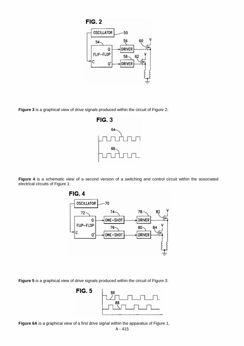
A - 415
Figure 3 is a graphical view of drive signals produced within the circuit of Figure 2:
Figure 4 is a schematic view of a second version of a switching and control circuit within the associated electrical circuits of Figure 1:
Figure 5 is a graphical view of drive signals produced within the circuit of Figure 3:
Figure 6A is a graphical view of a first drive signal within the apparatus of Figure 1,
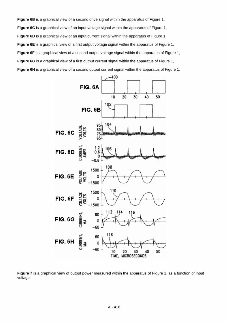
A - 416
Figure 6B is a graphical view of a second drive signal within the apparatus of Figure 1,
Figure 6C is a graphical view of an input voltage signal within the apparatus of Figure 1,
Figure 6D is a graphical view of an input current signal within the apparatus of Figure 1,
Figure 6E is a graphical view of a first output voltage signal within the apparatus of Figure 1,
Figure 6F is a graphical view of a second output voltage signal within the apparatus of Figure 1,
Figure 6G is a graphical view of a first output current signal within the apparatus of Figure 1,
Figure 6H is a graphical view of a second output current signal within the apparatus of Figure 1:
Figure 7 is a graphical view of output power measured within the apparatus of Figure 1, as a function of input voltage:
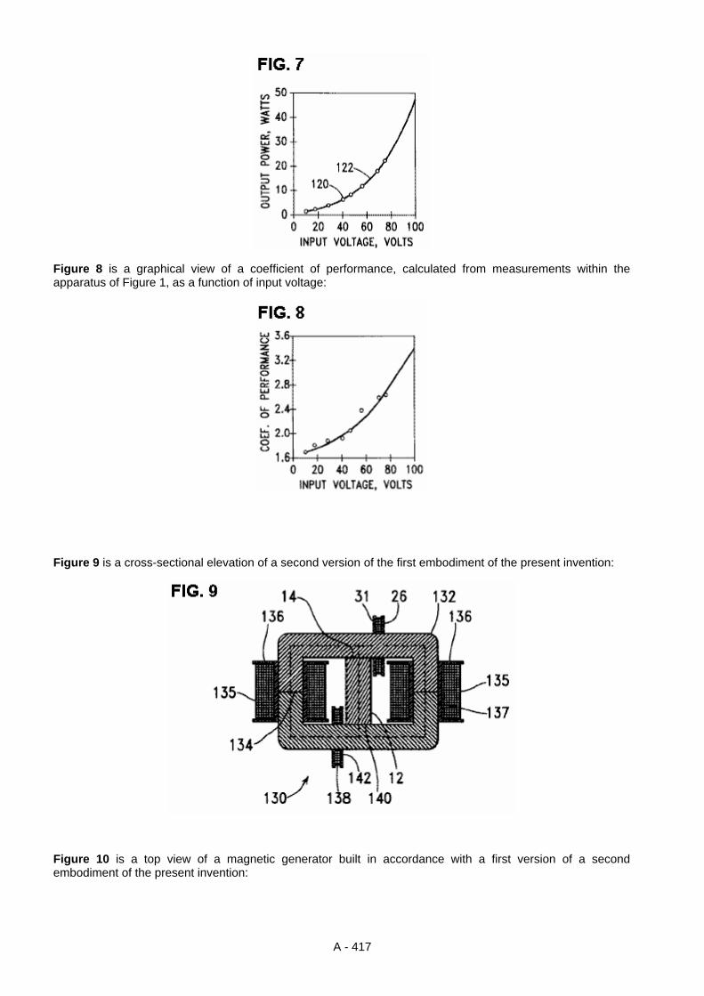
A - 417
Figure 8 is a graphical view of a coefficient of performance, calculated from measurements within the apparatus of Figure 1, as a function of input voltage:
Figure 9 is a cross-sectional elevation of a second version of the first embodiment of the present invention:
Figure 10 is a top view of a magnetic generator built in accordance with a first version of a second embodiment of the present invention:
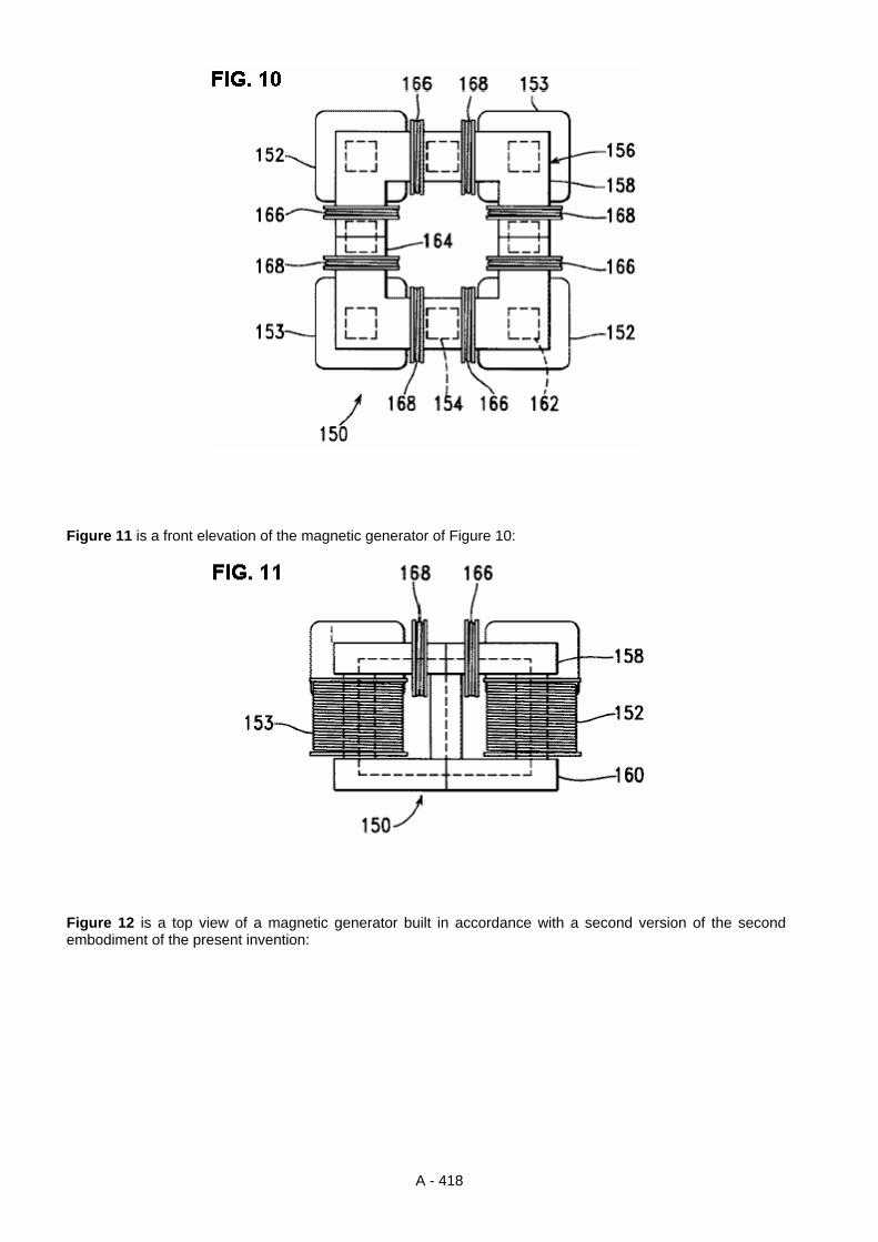
A - 418
Figure 11 is a front elevation of the magnetic generator of Figure 10:
Figure 12 is a top view of a magnetic generator built in accordance with a second version of the second embodiment of the present invention:

A - 419
DETAILED DESCRIPTION OF THE INVENTION:
Fig.1 is a partly schematic front elevation, of an electromagnetic generator 10, built in accordance with a first embodiment of the present invention, to include a permanent magnet 12 to supply input lines of magnetic flux moving from the north pole 14 of the magnet 12, outward into magnetic flux path core material 16.
The flux path core material 16 is configured to form a right magnetic path 18 and a left magnetic path 20, both of which extend externally between the north pole 14 and the south pole 22 of the magnet 12.
The electromagnetic generator 10 is driven by means of a switching and control circuit 24, which alternately drives electrical current through a right input coil 26 and a left input coil 28. These input coils each extend around a portion of the core material 16, with the right input coil 26 surrounding a portion of the right magnetic path 18 and with the left input coil 28 surrounding a portion of the left magnetic path 20. A right output coil 29 also surrounds a portion of the right magnetic path 18, while a left output coil 30 surrounds a portion of the left magnetic path 20.
In accordance with a preferred version of the present invention, the switching and control circuit 24 and the input coils 26, 28 are arranged so that, when the right input coil 26 is energised, a north magnetic pole is present at its left end 31, the end closest to the north pole 14 of the permanent magnet 12, and so that, when the left input coil 28 is energised, a north magnetic pole is present at its right end 32, which is also the end closest to the north pole 14 of the permanent magnet 12. Thus, when the right input coil 26 is magnetised, magnetic flux from the permanent magnet 12 is repelled from extending through the right input coil 26. Similarly, when the left input coil 28 is magnetised, magnetic flux from the permanent magnet 12 is repelled from extending through the left input coil 28.
Thus, it is seen that driving electrical current through the right input coil 26 opposes a concentration of flux from the permanent magnet 12 within the right magnetic path 18, causing at least some of this flux to be transferred to the left magnetic path 20. On the other hand, driving electrical current through the left input coil 28 opposes a concentration of flux from the permanent magnet 12 within the left magnetic path 20, causing at least some of this flux to be transferred to the right magnetic path 18.
While in the example of Fig.1, the input coils 26, 28 are placed on either side of the north pole of the permanent magnet 12, being arranged along a portion of the core 16 extending from the north pole of the permanent magnet 12, it is understood that the input coils 26, 28 could as easily be alternately placed on either side of the south pole of the permanent magnet 12, being arranged along a portion of the core 16 extending from the south pole of the permanent magnet 12, with the input coils 26, 28 being wired to form, when energised, magnetic fields having south poles directed toward the south pole of the permanent magnet 12. In general, the input coils 26, 28 are arranged along the magnetic core on either side of an end of the permanent magnet forming a first pole, such as a north pole, with the input coils being arranged to produce magnetic fields of the polarity of the first pole directed toward the first pole of the permanent magnet.
Further in accordance with a preferred version of the present invention, the input coils 26, 28 are never driven with so much current that the core material 16 becomes saturated. Driving the core material 16 to saturation means that subsequent increases in input current can occur without effecting corresponding changes in magnetic flux, and therefore that input power can be wasted. In this way, the apparatus of the present
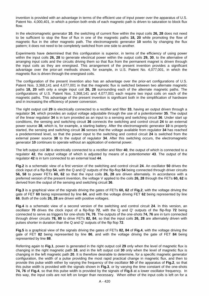
A - 420
invention is provided with an advantage in terms of the efficient use of input power over the apparatus of U.S. Patent No. 4,000,401, in which a portion both ends of each magnetic path is driven to saturation to block flux flow.
In the electromagnetic generator 10, the switching of current flow within the input coils 26, 28 does not need to be sufficient to stop the flow of flux in one of the magnetic paths 18, 20 while promoting the flow of magnetic flux in the other magnetic path. The electromagnetic generator 10 works by changing the flux pattern; it does not need to be completely switched from one side to another.
Experiments have determined that this configuration is superior, in terms of the efficiency of using power within the input coils 26, 28 to generate electrical power within the output coils 29, 30, to the alternative of arranging input coils and the circuits driving them so that flux from the permanent magnet is driven through the input coils as they are energised. This arrangement of the present invention provides a significant advantage over the prior-art methods shown, for example, in U.S. Patent No. 4,077,001, in which the magnetic flux is driven through the energised coils.
The configuration of the present invention also has an advantage over the prior-art configurations of U.S. Patent Nos. 3,368,141 and 4,077,001 in that the magnetic flux is switched between two alternate magnetic paths 18, 20 with only a single input coil 26, 28 surrounding each of the alternate magnetic paths. The configurations of U.S. Patent Nos. 3,368,141 and 4,077,001 each require two input coils on each of the magnetic paths. This advantage of the present invention is significant both in the simplification of hardware and in increasing the efficiency of power conversion.
The right output coil 29 is electrically connected to a rectifier and filter 33, having an output driven through a regulator 34, which provides an output voltage adjustable through the use of a potentiometer 35. The output of the linear regulator 34 is in turn provided as an input to a sensing and switching circuit 36. Under start up conditions, the sensing and switching circuit 36 connects the switching and control circuit 24 to an external power source 38, which is, for example, a starting battery. After the electromagnetic generator 10 is properly started, the sensing and switching circuit 36 senses that the voltage available from regulator 34 has reached a predetermined level, so that the power input to the switching and control circuit 24 is switched from the external power source 38 to the output of regulator 34. After this switching occurs, the electromagnetic generator 10 continues to operate without an application of external power.
The left output coil 30 is electrically connected to a rectifier and filter 40, the output of which is connected to a regulator 42, the output voltage of which is adjusted by means of a potentiometer 43. The output of the regulator 42 is in turn connected to an external load 44.
Fig.2 is a schematic view of a first version of the switching and control circuit 24. An oscillator 50 drives the clock input of a flip-flop 54, with the Q and Q' outputs of the flip-flop 54 being connected through driver circuits 56, 58 to power FETs 60, 62 so that the input coils 26, 28 are driven alternately. In accordance with a preferred version of the present invention, the voltage V applied to the coils 26, 28 through the FETs 60, 62 is derived from the output of the sensing and switching circuit 36.
Fig.3 is a graphical view of the signals driving the gates of FETs 60, 62 of Fig.2, with the voltage driving the gate of FET 60 being represented by line 64, and with the voltage driving FET 62 being represented by line 66. Both of the coils 26, 28 are driven with positive voltages.
Fig.4 is a schematic view of a second version of the switching and control circuit 24. In this version, an oscillator 70 drives the clock input of a flip-flop 72, with the Q and Q' outputs of the flip-flop 72 being connected to serve as triggers for one-shots 74, 76. The outputs of the one-shots 74, 76 are in turn connected through driver circuits 78, 80 to drive FETs 82, 84, so that the input coils 26, 28 are alternately driven with pulses shorter in duration than the Q and Q' outputs of the flip flop 72.
Fig.5 is a graphical view of the signals driving the gates of FETs 82, 84 of Fig.4, with the voltage driving the gate of FET 82 being represented by line 86, and with the voltage driving the gate of FET 84 being represented by line 88.
Referring again to Fig.1, power is generated in the right output coil 29 only when the level of magnetic flux is changing in the right magnetic path 18, and in the left output coil 30 only when the level of magnetic flux is changing in the left magnetic path 20. It is therefore desirable to determine, for a specific magnetic generator configuration, the width of a pulse providing the most rapid practical change in magnetic flux, and then to provide this pulse width either by varying the frequency of the oscillator 50 of the apparatus of Fig.2, so that this pulse width is provided with the signals shown in Fig.3, or by varying the time constant of the one-shots 74, 76 of Fig.4, so that this pulse width is provided by the signals of Fig.5 at a lower oscillator frequency. In this way, the input coils are not left on longer than necessary. When either of the input coils is left on for a

A - 421
period of time longer than that necessary to produce the change in flux direction, power is being wasted through heating within the input coil without additional generation of power in the corresponding output coil.
A number of experiments have been conducted to determine the adequacy of an electromagnetic generator built as the generator 10 in Fig.1, to produce power both to drive the switching and control logic, providing power to the input coils 26, 28, and to drive an external load 44. In the configuration used in this experiment, the input coils 26, 28 had 40 turns of 18-gauge copper wire, and the output coils 29, 30 had 450 turns of 18-gauge copper wire. The permanent magnet 12 had a height of 40 mm (1.575 in. between its north and south poles, in the direction of arrow 89, a width of 25.4 mm (1.00 in.), in the direction of arrow 90, and in the other direction, a depth of 38.1 mm (1.50 in.). The core 16 had a height, in the direction of arrow 89, of 90 mm (3.542 in.), a width, in the direction of arrow 90, of 135 mm (5.315 in.) and a depth of 70 mm (2.756 in.). The core 16 had a central hole with a height, in the direction of arrow 89, of 40 mm (1.575 mm) to accommodate the magnet 12, and a width, in the direction of arrow 90, of 85 mm (3.346 in.). The core 16 was fabricated of two "C"-shaped halves, joined at lines 92, to accommodate the winding of output coils 29, 30 and input coils 26, 28 over the core material.
The core material was a laminated iron-based magnetic alloy sold by Honeywell as METGLAS Magnetic Alloy 2605SA1. The magnet material was a combination of iron, neodymium, and boron.
The input coils 26, 28 were driven at an oscillator frequency of 87.5 KHz, which was determined to produce optimum efficiency using a switching control circuit configured as shown in Fig.2. This frequency has a period of 11.45 microseconds. The flip flop 54 is arranged, for example, to be set and reset on rising edges of the clock signal input from the oscillator, so that each pulse driving one of the FETs 60, 62 has a duration of 11.45 microseconds, and so that sequential pulses are also separated to each FET are also separated by 11.45 microseconds.
Fig.6A to Fig.6H, are graphical views of signals which occurred simultaneously during the operation of the apparatus shown in Fig.1 and Fig.2, when the input voltage applied was 75 volts. Fig.6A shows a first drive signal 100 driving FET 60, which conducts to drive the right input coil 26. Fig.6B shows a second drive signal 102, driving FET 62, which, when it conducts, provides the drive to the left input coil 28.
Fig.6C and Fig.6D show voltage and current signals produced when the current driving the FETs 60, 62 is provided from a battery source. Fig.6C shows the level 104 of voltage V. While the nominal voltage of the battery was 75 volts, a decaying transient signal 106 is superimposed on this voltage each time one of the FETs 60, 62 is switched on. The specific pattern of this transient signal depends on the internal resistance of the battery, as well as on a number of characteristics of the magnetic generator 10. Similarly, Fig.6D shows the current 106 flowing into FETs 60, 62 from the battery source. Since the signals 104, 106 show the effects of current flowing into both FETs 60, 62 the transient spikes are 11.45 microseconds apart.
Figs.6E to 6H, show the voltage and current levels measured at the output coils 29, 30. Fig.6E shows a voltage output signal 108 of the right output coil 29, while Fig.6F shows a voltage output signal 110 of the left output coil 30. For example, the output current signal 116 of the right output coil 29 includes a first transient spike 112 caused when a pulse of current is generated in the left input coil 28 in order to boost the magnetic flux passing through the right magnetic path 18, and a second transient spike 114 caused when the left input coil 28 is turned off as the right input coil 26 is being turned on. Fig.6G shows an output current signal 116 of the right output coil 29, while Fig.6H shows an output current signal 118 of the left output coil 30.
Fig.7 is a graphical view of output power measured using the electromagnetic generator 10 and eight levels of input voltage, varying from 10v to 75v. The oscillator frequency was retained at 87.5 KHz. The measured values are represented by points 120, while the curve 122 is generated by polynomial regression, (a least squares fit).
Fig.8 is a graphical view of a coefficient of performance, defined as the ratio of the output power to the input power, for each of the measurement points shown in Fig.7. At each measurement point, the output power was substantially higher than the input power. Real power measurements were computed at each data point using measured voltage and current levels, with the results being averaged over the period of the signal. These measurements agree with RMS power measured using a Textronic THS730 digital oscilloscope.
While the electromagnetic generator 10 was capable of operation at much higher voltages and currents without saturation, the input voltage was limited to 75 volts because of voltage limitations of the switching circuits being used. Those familiar with electronics will understand that components for switching circuits capable of handling higher voltages are readily available for use in this application.
The experimentally-measured data were extrapolated to predict operation at an input voltage of 100 volts, with the input current being 140 mA, the input power being 14 watts, and with a resulting output power being

A - 422
48 watts for each of the two output coils 29, 30, at an average output current of 12 mA and an average output voltage of 4000 volts. This means that for each of the output coils 29, 30, the coefficient of performance (“COP”) would be 3.44.
While an output voltage of 4000 volts may be needed for some applications, the output voltage can also be varied through a simple change in the configuration of the electromagnetic generator 10. The output voltage is readily reduced by reducing the number of turns in the output windings. If this number of turns is decreased from 450 to 12, the output voltage is dropped to 106.7, with a resulting increase in output current to 0.5 amps for each output coil 29, 30, (i.e. 53 watts). In this way, the output current and voltage of the electromagnetic generator can be varied by varying the number of turns of the output coils 29, 30, without making a substantial change in the output power, which is instead determined by the input current, which determines the amount of magnetic flux shuttled during the switching process.
All of the Coefficients Of Performance were significantly greater than 1. These are plotted in Fig.8 and they indicate that the output power levels measured in each of the output coils 29, 30 were substantially greater than the corresponding input power levels driving both of the input coils 26, 28. Therefore, it is apparent that the electromagnetic generator 10 can be built in a self-powered form, as discussed above in reference to Fig.1. In the example of Fig.1, except for a brief application of power from the external power source 38 to start the process of power generation, the power required to drive the input coils 26, 28 is derived entirely from power developed within the right output coil 29. If the power generated in the single output coil 29, is more than sufficient to drive the input coils 26, 28, an additional load 126 may be added to be driven with power generated in the output coil 29. On the other hand, each of the output coils 29, 30 may be used to drive a portion of the input coil power requirements, for example, output coils 26 can provide the driving voltage V for FET 60 while output coil 28 can provide the driving voltage V for FET 62.
Regarding thermodynamic considerations, it is noted that when the electromagnetic generator 10 is operating, it is an open system not in thermodynamic equilibrium. The system receives static energy from the magnetic flux of the permanent magnet. Because the electromagnetic generator 10 is self-switched without an additional energy input, the thermodynamic operation of the system is an open dissipative system, receiving, collecting, and dissipating energy from its environment; in this case, from the magnetic flux stored within the permanent magnet. Continued operation of the electromagnetic generator 10 causes demagnetisation of the permanent magnet. The use of a magnetic material including rare earth elements, such as a samarium cobalt material or a material including iron, neodymium, and boron is preferable within the present invention, since such a magnetic material has a relatively long life in this application.
Thus, an electromagnetic generator operating in accordance with the present invention should not be considered as a perpetual-motion machine, but rather as a system in which flux radiated from a permanent magnet is converted into electricity, which is used both to power the apparatus and to power an external load. This is analogous to a system including a nuclear reactor, in which a number of fuel rods radiate energy which is used to keep the chain reaction going and to heat water for the generation of electricity to drive external loads.
Fig.9 is a cross-sectional elevation of an electromagnetic generator 130 built in accordance with a second version of the first embodiment of the present invention. This electromagnetic generator 130 is generally similar in construction and operation to the electromagnetic generator 10 built in accordance with the first version of this embodiment, except that the magnetic core 132 of the electromagnetic generator 10 is built in two halves joined along lines 134, allowing each of the output coils 135 to be wound on a plastic bobbin 136 before being placed over the legs 137 of the core 132.
Fig.9 also shows an alternate placement of an input coil 138. In the example of Fig.1, both of the input coils 26, 28 were placed on the upper portion of the magnetic core 16, with these coils being configured to generate magnetic fields having north magnetic poles at the inner ends 31, 32 of the coils 26, 28, with these north magnetic poles thus being closest to the end 14 of the permanent magnet 12 having its north magnetic pole. In the example of Fig.9, a first input coil 26 is as described above in reference to Fig.1, but the second input coil 138 is placed adjacent the south pole 140 of the permanent magnet 12. This input coil 138 is configured to generate a south magnetic pole at its inner end 142, so that, when input coil 138 is turned on, flux from the permanent magnet 12 is directed away from the left magnetic path 20 into the right magnetic path 18.
Fig.10 and Fig.11 show an electromagnetic generator 150 built in accordance with a first version of a second embodiment of the present invention, with Fig.10 being a top view, and Fig.11 being a front elevation. This electromagnetic generator 150 includes an output coil 152, 153 at each corner, and a permanent magnet 154 extending along each side between output coils. The magnetic core 156 includes an upper plate 158, a lower plate 160, and a square post 162 extending within each output coil 152, 153. Both the upper plate 158 and the lower plate 160 include central apertures 164.
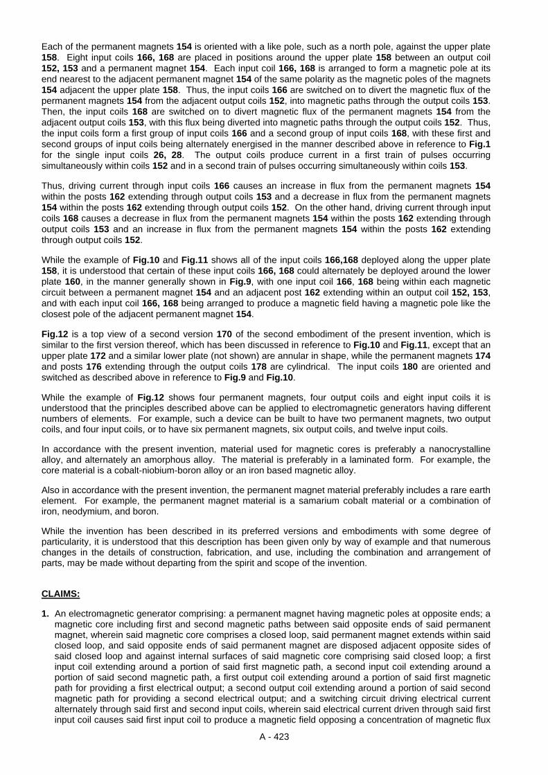
A - 423
Each of the permanent magnets 154 is oriented with a like pole, such as a north pole, against the upper plate 158. Eight input coils 166, 168 are placed in positions around the upper plate 158 between an output coil 152, 153 and a permanent magnet 154. Each input coil 166, 168 is arranged to form a magnetic pole at its end nearest to the adjacent permanent magnet 154 of the same polarity as the magnetic poles of the magnets 154 adjacent the upper plate 158. Thus, the input coils 166 are switched on to divert the magnetic flux of the permanent magnets 154 from the adjacent output coils 152, into magnetic paths through the output coils 153. Then, the input coils 168 are switched on to divert magnetic flux of the permanent magnets 154 from the adjacent output coils 153, with this flux being diverted into magnetic paths through the output coils 152. Thus, the input coils form a first group of input coils 166 and a second group of input coils 168, with these first and second groups of input coils being alternately energised in the manner described above in reference to Fig.1 for the single input coils 26, 28. The output coils produce current in a first train of pulses occurring simultaneously within coils 152 and in a second train of pulses occurring simultaneously within coils 153.
Thus, driving current through input coils 166 causes an increase in flux from the permanent magnets 154 within the posts 162 extending through output coils 153 and a decrease in flux from the permanent magnets 154 within the posts 162 extending through output coils 152. On the other hand, driving current through input coils 168 causes a decrease in flux from the permanent magnets 154 within the posts 162 extending through output coils 153 and an increase in flux from the permanent magnets 154 within the posts 162 extending through output coils 152.
While the example of Fig.10 and Fig.11 shows all of the input coils 166,168 deployed along the upper plate 158, it is understood that certain of these input coils 166, 168 could alternately be deployed around the lower plate 160, in the manner generally shown in Fig.9, with one input coil 166, 168 being within each magnetic circuit between a permanent magnet 154 and an adjacent post 162 extending within an output coil 152, 153, and with each input coil 166, 168 being arranged to produce a magnetic field having a magnetic pole like the closest pole of the adjacent permanent magnet 154.
Fig.12 is a top view of a second version 170 of the second embodiment of the present invention, which is similar to the first version thereof, which has been discussed in reference to Fig.10 and Fig.11, except that an upper plate 172 and a similar lower plate (not shown) are annular in shape, while the permanent magnets 174 and posts 176 extending through the output coils 178 are cylindrical. The input coils 180 are oriented and switched as described above in reference to Fig.9 and Fig.10.
While the example of Fig.12 shows four permanent magnets, four output coils and eight input coils it is understood that the principles described above can be applied to electromagnetic generators having different numbers of elements. For example, such a device can be built to have two permanent magnets, two output coils, and four input coils, or to have six permanent magnets, six output coils, and twelve input coils.
In accordance with the present invention, material used for magnetic cores is preferably a nanocrystalline alloy, and alternately an amorphous alloy. The material is preferably in a laminated form. For example, the core material is a cobalt-niobium-boron alloy or an iron based magnetic alloy.
Also in accordance with the present invention, the permanent magnet material preferably includes a rare earth element. For example, the permanent magnet material is a samarium cobalt material or a combination of iron, neodymium, and boron.
While the invention has been described in its preferred versions and embodiments with some degree of particularity, it is understood that this description has been given only by way of example and that numerous changes in the details of construction, fabrication, and use, including the combination and arrangement of parts, may be made without departing from the spirit and scope of the invention.
CLAIMS:
1. An electromagnetic generator comprising: a permanent magnet having magnetic poles at opposite ends; a magnetic core including first and second magnetic paths between said opposite ends of said permanent magnet, wherein said magnetic core comprises a closed loop, said permanent magnet extends within said closed loop, and said opposite ends of said permanent magnet are disposed adjacent opposite sides of said closed loop and against internal surfaces of said magnetic core comprising said closed loop; a first input coil extending around a portion of said first magnetic path, a second input coil extending around a portion of said second magnetic path, a first output coil extending around a portion of said first magnetic path for providing a first electrical output; a second output coil extending around a portion of said second magnetic path for providing a second electrical output; and a switching circuit driving electrical current alternately through said first and second input coils, wherein said electrical current driven through said first input coil causes said first input coil to produce a magnetic field opposing a concentration of magnetic flux
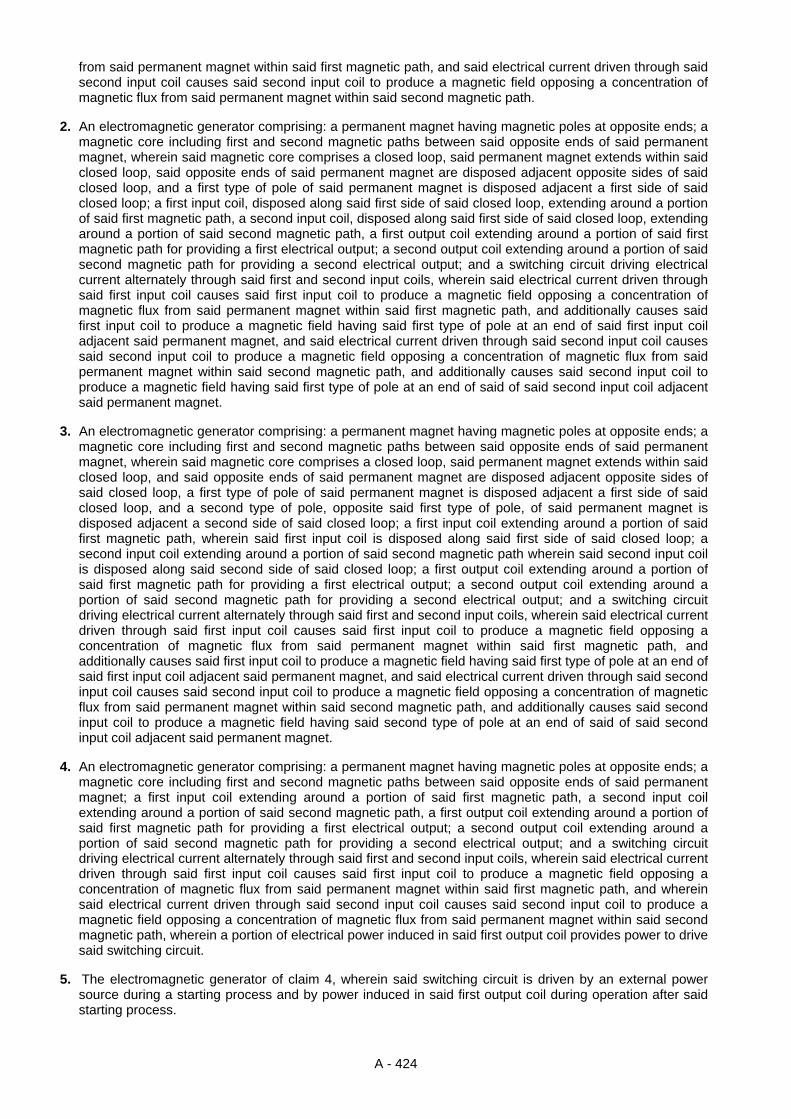
A - 424
from said permanent magnet within said first magnetic path, and said electrical current driven through said second input coil causes said second input coil to produce a magnetic field opposing a concentration of magnetic flux from said permanent magnet within said second magnetic path.
2. An electromagnetic generator comprising: a permanent magnet having magnetic poles at opposite ends; a magnetic core including first and second magnetic paths between said opposite ends of said permanent magnet, wherein said magnetic core comprises a closed loop, said permanent magnet extends within said closed loop, said opposite ends of said permanent magnet are disposed adjacent opposite sides of said closed loop, and a first type of pole of said permanent magnet is disposed adjacent a first side of said closed loop; a first input coil, disposed along said first side of said closed loop, extending around a portion of said first magnetic path, a second input coil, disposed along said first side of said closed loop, extending around a portion of said second magnetic path, a first output coil extending around a portion of said first magnetic path for providing a first electrical output; a second output coil extending around a portion of said second magnetic path for providing a second electrical output; and a switching circuit driving electrical current alternately through said first and second input coils, wherein said electrical current driven through said first input coil causes said first input coil to produce a magnetic field opposing a concentration of magnetic flux from said permanent magnet within said first magnetic path, and additionally causes said first input coil to produce a magnetic field having said first type of pole at an end of said first input coil adjacent said permanent magnet, and said electrical current driven through said second input coil causes said second input coil to produce a magnetic field opposing a concentration of magnetic flux from said permanent magnet within said second magnetic path, and additionally causes said second input coil to produce a magnetic field having said first type of pole at an end of said of said second input coil adjacent said permanent magnet.
3. An electromagnetic generator comprising: a permanent magnet having magnetic poles at opposite ends; a magnetic core including first and second magnetic paths between said opposite ends of said permanent magnet, wherein said magnetic core comprises a closed loop, said permanent magnet extends within said closed loop, and said opposite ends of said permanent magnet are disposed adjacent opposite sides of said closed loop, a first type of pole of said permanent magnet is disposed adjacent a first side of said closed loop, and a second type of pole, opposite said first type of pole, of said permanent magnet is disposed adjacent a second side of said closed loop; a first input coil extending around a portion of said first magnetic path, wherein said first input coil is disposed along said first side of said closed loop; a second input coil extending around a portion of said second magnetic path wherein said second input coil is disposed along said second side of said closed loop; a first output coil extending around a portion of said first magnetic path for providing a first electrical output; a second output coil extending around a portion of said second magnetic path for providing a second electrical output; and a switching circuit driving electrical current alternately through said first and second input coils, wherein said electrical current driven through said first input coil causes said first input coil to produce a magnetic field opposing a concentration of magnetic flux from said permanent magnet within said first magnetic path, and additionally causes said first input coil to produce a magnetic field having said first type of pole at an end of said first input coil adjacent said permanent magnet, and said electrical current driven through said second input coil causes said second input coil to produce a magnetic field opposing a concentration of magnetic flux from said permanent magnet within said second magnetic path, and additionally causes said second input coil to produce a magnetic field having said second type of pole at an end of said of said second input coil adjacent said permanent magnet.
4. An electromagnetic generator comprising: a permanent magnet having magnetic poles at opposite ends; a magnetic core including first and second magnetic paths between said opposite ends of said permanent magnet; a first input coil extending around a portion of said first magnetic path, a second input coil extending around a portion of said second magnetic path, a first output coil extending around a portion of said first magnetic path for providing a first electrical output; a second output coil extending around a portion of said second magnetic path for providing a second electrical output; and a switching circuit driving electrical current alternately through said first and second input coils, wherein said electrical current driven through said first input coil causes said first input coil to produce a magnetic field opposing a concentration of magnetic flux from said permanent magnet within said first magnetic path, and wherein said electrical current driven through said second input coil causes said second input coil to produce a magnetic field opposing a concentration of magnetic flux from said permanent magnet within said second magnetic path, wherein a portion of electrical power induced in said first output coil provides power to drive said switching circuit.
5. The electromagnetic generator of claim 4, wherein said switching circuit is driven by an external power source during a starting process and by power induced in said first output coil during operation after said starting process.

A - 425
6. The electromagnetic generator of claim 2, wherein said magnetic core is composed of a nanocrystalline magnetic alloy.
7. The electromagnetic generator of claim 6, wherein said nanocrystalline magnetic alloy is a cobalt-niobium-boron alloy.
8. The electromagnetic generator of claim 6, wherein said nanocrystalline magnetic alloy is an iron-based alloy.
9. The electromagnetic generator of claim 2, wherein said changes in flux density within said magnetic core occur without driving said magnetic core to magnetic saturation.
10. The electromagnetic generator of claim 2, wherein said switching circuit drives said electrical current through said first input coil in response to a first train of pulses, said switching circuit drives said electrical current through said second input coil in response to a second train of pulses, alternating with pulses within said first train of pulses, and said pulses in said first and second trains of pulses are approximately 11.5 milliseconds in duration.
11. The electromagnetic generator of claim 2, wherein said permanent magnet is composed of a material including a rare earth element.
12. The electromagnetic generator of claim 11, wherein said permanent magnet is composed essentially of samarium cobalt.
13. The electromagnetic generator of claim 11, wherein said permanent magnet is composed essentially of iron, neodymium, and boron.
14. An electromagnetic generator comprising: a magnetic core including a pair of spaced-apart plates, wherein each of said spaced-apart plates includes a central aperture, and first and second pluralities of posts extending between said spaced-apart plates; a plurality of permanent magnets extending individually between said pair of spaced-apart plates and between adjacent posts within said plurality of posts, wherein each permanent magnet within said plurality of permanent magnets has magnetic poles at opposite ends, wherein all magnets within said plurality of magnets are oriented to produce magnetic fields having a common direction; first and second pluralities of input coils, wherein each input coil within said first and second pluralities of input coils extends around a portion of a plate within said spaced-apart plates between a post in said plurality of posts and a permanent magnet in said plurality of permanent magnets; an output coil extending around each post in said first and second pluralities of posts for providing an electrical output; a switching circuit driving electrical current alternatively through said first and second pluralities of input coils, wherein said electrical current driven through each input coil in said first plurality of input coils causes an increase in magnetic flux within each post within said first plurality of posts from permanent magnets on each side of said post and a decrease in magnetic flux within each post within said second plurality of posts from permanent magnets on each side of said post, and wherein said electrical current driven through input coil in said second plurality of input coils causes a decrease in magnetic flux within each post within said first plurality of posts from permanent magnets on each side of said post and an increase in magnetic flux within each post within said second plurality of posts from permanent magnets on each side of said post.
15. The electromagnetic generator of claim 14, wherein each input coil extends around a portion of a magnetic path through said magnetic core between said opposite ends a permanent magnet adjacent said input coil, said magnetic path extends through a post within said magnetic core adjacent said input coil, and driving electrical current through said input coil causes said input coil to produce a magnetic field opposing a concentration of magnetic flux within said magnetic path.
16. The electromagnetic generator of claim 14, wherein said switching circuit is driven by an external power source during a starting process and by power induced in said output coils during operation after said starting process.
17. The electromagnetic generator of claim 14, wherein said magnetic core is composed of a nanocrystalline magnetic alloy.
18. The electromagnetic generator of claim 2, wherein a portion of electrical power induced in said first output coil provides power to drive said switching circuit.
19. The electromagnetic generator of claim 18, wherein said switching circuit is driven by an external power source during a starting process and by power induced in said first output coil during operation after said starting process.
A - 426
20. The electromagnetic generator of claim 3, wherein a portion of electrical power induced in said first output coil provides power to drive said switching circuit.
21. The electromagnetic generator of claim 20, wherein said switching circuit is driven by an external power source during a starting process and by power induced in said first output coil during operation after said starting process.
22. The electromagnetic generator of claim 3, wherein said magnetic core is composed of a nanocrystalline magnetic alloy.
23. The electromagnetic generator of claim 22, wherein said nanocrystalline magnetic alloy is a cobalt-niobium-boron alloy.
24. The electromagnetic generator of claim 22, wherein said nanocrystalline magnetic alloy is an iron-based alloy.
25. The electromagnetic generator of claim 3, wherein said changes in flux density within said magnetic core occur without driving said magnetic core to magnetic saturation.
26. The electromagnetic generator of claim 3, wherein said switching circuit drives said electrical current through said first input coil in response to a first train of pulses, said switching circuit drives said electrical current through said second input coil in response to a second train of pulses, alternating with pulses within said first train of pulses, and said pulses in said first and second trains of pulses are approximately 11.5 milliseconds in duration.
27. The electromagnetic generator of claim 3, wherein said permanent magnet is composed of a material including a rare earth element.
28. The electromagnetic generator of claim 27, wherein said permanent magnet is composed essentially of samarium cobalt.
29. The electromagnetic generator of claim 27, wherein said permanent magnet is composed essentially of iron, neodymium, and boron.
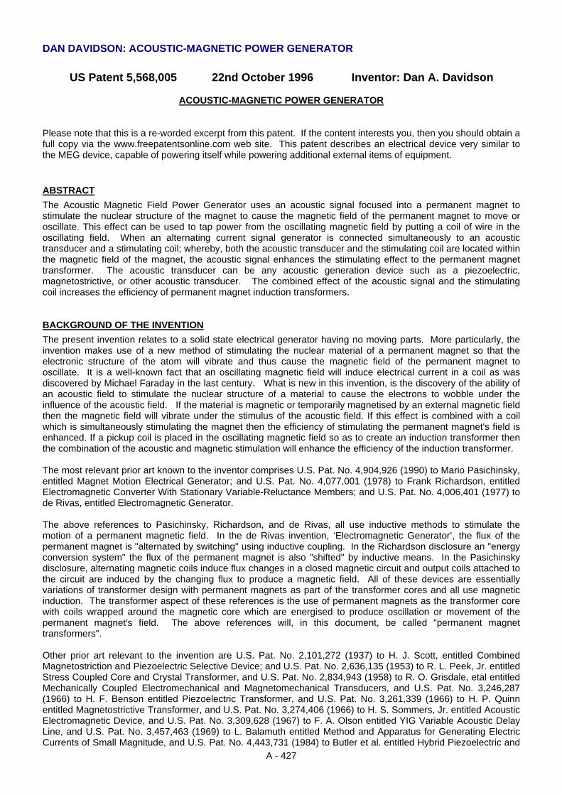
A - 427
DAN DAVIDSON: ACOUSTIC-MAGNETIC POWER GENERATOR
US Patent 5,568,005 22nd October 1996 Inventor: Dan A. Davidson
ACOUSTIC-MAGNETIC POWER GENERATOR Please note that this is a re-worded excerpt from this patent. If the content interests you, then you should obtain a full copy via the www.freepatentsonline.com web site. This patent describes an electrical device very similar to the MEG device, capable of powering itself while powering additional external items of equipment. ABSTRACT The Acoustic Magnetic Field Power Generator uses an acoustic signal focused into a permanent magnet to stimulate the nuclear structure of the magnet to cause the magnetic field of the permanent magnet to move or oscillate. This effect can be used to tap power from the oscillating magnetic field by putting a coil of wire in the oscillating field. When an alternating current signal generator is connected simultaneously to an acoustic transducer and a stimulating coil; whereby, both the acoustic transducer and the stimulating coil are located within the magnetic field of the magnet, the acoustic signal enhances the stimulating effect to the permanent magnet transformer. The acoustic transducer can be any acoustic generation device such as a piezoelectric, magnetostrictive, or other acoustic transducer. The combined effect of the acoustic signal and the stimulating coil increases the efficiency of permanent magnet induction transformers. BACKGROUND OF THE INVENTION The present invention relates to a solid state electrical generator having no moving parts. More particularly, the invention makes use of a new method of stimulating the nuclear material of a permanent magnet so that the electronic structure of the atom will vibrate and thus cause the magnetic field of the permanent magnet to oscillate. It is a well-known fact that an oscillating magnetic field will induce electrical current in a coil as was discovered by Michael Faraday in the last century. What is new in this invention, is the discovery of the ability of an acoustic field to stimulate the nuclear structure of a material to cause the electrons to wobble under the influence of the acoustic field. If the material is magnetic or temporarily magnetised by an external magnetic field then the magnetic field will vibrate under the stimulus of the acoustic field. If this effect is combined with a coil which is simultaneously stimulating the magnet then the efficiency of stimulating the permanent magnet's field is enhanced. If a pickup coil is placed in the oscillating magnetic field so as to create an induction transformer then the combination of the acoustic and magnetic stimulation will enhance the efficiency of the induction transformer. The most relevant prior art known to the inventor comprises U.S. Pat. No. 4,904,926 (1990) to Mario Pasichinsky, entitled Magnet Motion Electrical Generator; and U.S. Pat. No. 4,077,001 (1978) to Frank Richardson, entitled Electromagnetic Converter With Stationary Variable-Reluctance Members; and U.S. Pat. No. 4,006,401 (1977) to de Rivas, entitled Electromagnetic Generator. The above references to Pasichinsky, Richardson, and de Rivas, all use inductive methods to stimulate the motion of a permanent magnetic field. In the de Rivas invention, ‘Electromagnetic Generator’, the flux of the permanent magnet is "alternated by switching" using inductive coupling. In the Richardson disclosure an "energy conversion system" the flux of the permanent magnet is also "shifted" by inductive means. In the Pasichinsky disclosure, alternating magnetic coils induce flux changes in a closed magnetic circuit and output coils attached to the circuit are induced by the changing flux to produce a magnetic field. All of these devices are essentially variations of transformer design with permanent magnets as part of the transformer cores and all use magnetic induction. The transformer aspect of these references is the use of permanent magnets as the transformer core with coils wrapped around the magnetic core which are energised to produce oscillation or movement of the permanent magnet's field. The above references will, in this document, be called "permanent magnet transformers". Other prior art relevant to the invention are U.S. Pat. No. 2,101,272 (1937) to H. J. Scott, entitled Combined Magnetostriction and Piezoelectric Selective Device; and U.S. Pat. No. 2,636,135 (1953) to R. L. Peek, Jr. entitled Stress Coupled Core and Crystal Transformer, and U.S. Pat. No. 2,834,943 (1958) to R. O. Grisdale, etal entitled Mechanically Coupled Electromechanical and Magnetomechanical Transducers, and U.S. Pat. No. 3,246,287 (1966) to H. F. Benson entitled Piezoelectric Transformer, and U.S. Pat. No. 3,261,339 (1966) to H. P. Quinn entitled Magnetostrictive Transformer, and U.S. Pat. No. 3,274,406 (1966) to H. S. Sommers, Jr. entitled Acoustic Electromagnetic Device, and U.S. Pat. No. 3,309,628 (1967) to F. A. Olson entitled YIG Variable Acoustic Delay Line, and U.S. Pat. No. 3,457,463 (1969) to L. Balamuth entitled Method and Apparatus for Generating Electric Currents of Small Magnitude, and U.S. Pat. No. 4,443,731 (1984) to Butler et al. entitled Hybrid Piezoelectric and
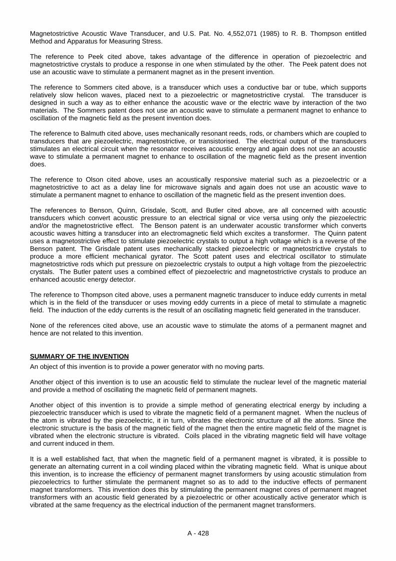
A - 428
Magnetostrictive Acoustic Wave Transducer, and U.S. Pat. No. 4,552,071 (1985) to R. B. Thompson entitled Method and Apparatus for Measuring Stress. The reference to Peek cited above, takes advantage of the difference in operation of piezoelectric and magnetostrictive crystals to produce a response in one when stimulated by the other. The Peek patent does not use an acoustic wave to stimulate a permanent magnet as in the present invention. The reference to Sommers cited above, is a transducer which uses a conductive bar or tube, which supports relatively slow helicon waves, placed next to a piezoelectric or magnetostrictive crystal. The transducer is designed in such a way as to either enhance the acoustic wave or the electric wave by interaction of the two materials. The Sommers patent does not use an acoustic wave to stimulate a permanent magnet to enhance to oscillation of the magnetic field as the present invention does. The reference to Balmuth cited above, uses mechanically resonant reeds, rods, or chambers which are coupled to transducers that are piezoelectric, magnetostrictive, or transistorised. The electrical output of the transducers stimulates an electrical circuit when the resonator receives acoustic energy and again does not use an acoustic wave to stimulate a permanent magnet to enhance to oscillation of the magnetic field as the present invention does. The reference to Olson cited above, uses an acoustically responsive material such as a piezoelectric or a magnetostrictive to act as a delay line for microwave signals and again does not use an acoustic wave to stimulate a permanent magnet to enhance to oscillation of the magnetic field as the present invention does. The references to Benson, Quinn, Grisdale, Scott, and Butler cited above, are all concerned with acoustic transducers which convert acoustic pressure to an electrical signal or vice versa using only the piezoelectric and/or the magnetostrictive effect. The Benson patent is an underwater acoustic transformer which converts acoustic waves hitting a transducer into an electromagnetic field which excites a transformer. The Quinn patent uses a magnetostrictive effect to stimulate piezoelectric crystals to output a high voltage which is a reverse of the Benson patent. The Grisdale patent uses mechanically stacked piezoelectric or magnetostrictive crystals to produce a more efficient mechanical gyrator. The Scott patent uses and electrical oscillator to stimulate magnetostrictive rods which put pressure on piezoelectric crystals to output a high voltage from the piezoelectric crystals. The Butler patent uses a combined effect of piezoelectric and magnetostrictive crystals to produce an enhanced acoustic energy detector. The reference to Thompson cited above, uses a permanent magnetic transducer to induce eddy currents in metal which is in the field of the transducer or uses moving eddy currents in a piece of metal to stimulate a magnetic field. The induction of the eddy currents is the result of an oscillating magnetic field generated in the transducer. None of the references cited above, use an acoustic wave to stimulate the atoms of a permanent magnet and hence are not related to this invention. SUMMARY OF THE INVENTION An object of this invention is to provide a power generator with no moving parts. Another object of this invention is to use an acoustic field to stimulate the nuclear level of the magnetic material and provide a method of oscillating the magnetic field of permanent magnets. Another object of this invention is to provide a simple method of generating electrical energy by including a piezoelectric transducer which is used to vibrate the magnetic field of a permanent magnet. When the nucleus of the atom is vibrated by the piezoelectric, it in turn, vibrates the electronic structure of all the atoms. Since the electronic structure is the basis of the magnetic field of the magnet then the entire magnetic field of the magnet is vibrated when the electronic structure is vibrated. Coils placed in the vibrating magnetic field will have voltage and current induced in them. It is a well established fact, that when the magnetic field of a permanent magnet is vibrated, it is possible to generate an alternating current in a coil winding placed within the vibrating magnetic field. What is unique about this invention, is to increase the efficiency of permanent magnet transformers by using acoustic stimulation from piezoelectrics to further stimulate the permanent magnet so as to add to the inductive effects of permanent magnet transformers. This invention does this by stimulating the permanent magnet cores of permanent magnet transformers with an acoustic field generated by a piezoelectric or other acoustically active generator which is vibrated at the same frequency as the electrical induction of the permanent magnet transformers.
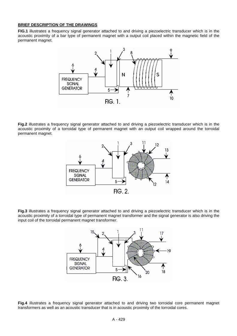
A - 429
BRIEF DESCRIPTION OF THE DRAWINGS FIG.1 illustrates a frequency signal generator attached to and driving a piezoelectric transducer which is in the acoustic proximity of a bar type of permanent magnet with a output coil placed within the magnetic field of the permanent magnet.
Fig.2 illustrates a frequency signal generator attached to and driving a piezoelectric transducer which is in the acoustic proximity of a torroidal type of permanent magnet with an output coil wrapped around the torroidal permanent magnet.
Fig.3 illustrates a frequency signal generator attached to and driving a piezoelectric transducer which is in the acoustic proximity of a torroidal type of permanent magnet transformer and the signal generator is also driving the input coil of the torroidal permanent magnet transformer.
Fig.4 illustrates a frequency signal generator attached to and driving two torroidal core permanent magnet transformers as well as an acoustic transducer that is in acoustic proximity of the torroidal cores.
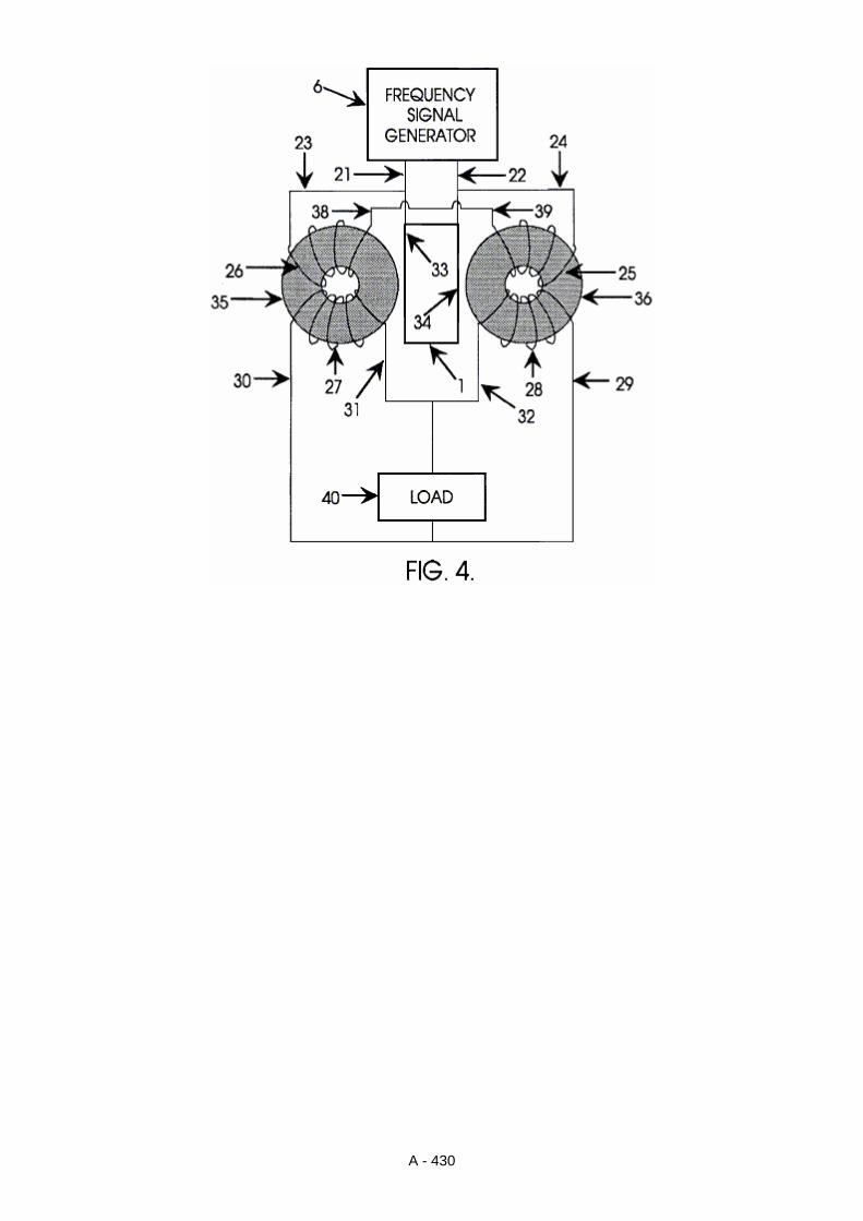
A - 430

A - 431
DETAILED DESCRIPTION OF THE INVENTION
In Fig.1, a frequency signal generator 6 is connected to a piezoelectric transducer 1 via wires 4 and 5 connected to the electrode surfaces of the piezoelectric transducer 2 and 3 respectively. The piezoelectric transducer 1 is made from a high dielectric material such as barium titanate or lead zirconate titanate or any other acoustic transducer material suitable for sonic and ultrasonic generators. The piezoelectric transducer 1 is placed in close proximity to the permanent magnet 7 such that the acoustic field of the piezoelectric transducer 1 can radiate into the permanent magnet material. A permanent magnet transformer shown as coil 8 is positioned in the magnetic field of the permanent magnet 7. When the piezoelectric transducer 1 is stimulated by the frequency generator 6 then a voltage and current is generated between the output leads 9 and 10 of the permanent magnet transformer.
Another embodiment of this invention is shown in Fig.2. which is similar to Fig.1, with a similar frequency signal generator 6 connected to a piezoelectric material 1 via wires 4 and 5 connected to the electrode surfaces of the piezoelectric transducer 2 and 3. The piezoelectric transducer 1 is as defined above, that is to say that it is constructed from a material suitable for sonic and ultrasonic generators. The piezoelectric transducer 1 is placed in close proximity to the permanent magnet 11 so that the acoustic field of the piezoelectric transducer 1 can radiate into the permanent magnet material. A permanent magnet transformer shown as coil 12 is placed in the magnetic field of the permanent magnet 11. When the piezoelectric transducer 1 is stimulated by the frequency generator 6 then a voltage and current is generated between the output leads 13 and 14 of the above defined magnetic transformer.
Fig.3 is similar to Fig.1 and Fig.2 with a frequency signal generator 6 connected to a piezoelectric transducer 1 via wires 4 and 5 connected to the electrode surfaces 2 and 3 of the piezoelectric transducer. The piezoelectric transducer 1 is as defined in the descriptions above. The signal generator 6 is also connected to the input coil 20
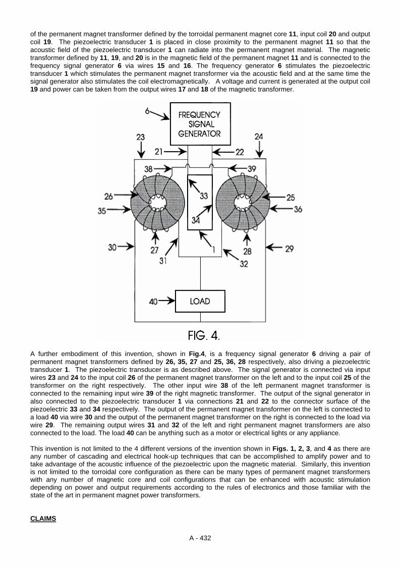
A - 432
of the permanent magnet transformer defined by the torroidal permanent magnet core 11, input coil 20 and output coil 19. The piezoelectric transducer 1 is placed in close proximity to the permanent magnet 11 so that the acoustic field of the piezoelectric transducer 1 can radiate into the permanent magnet material. The magnetic transformer defined by 11, 19, and 20 is in the magnetic field of the permanent magnet 11 and is connected to the frequency signal generator 6 via wires 15 and 16. The frequency generator 6 stimulates the piezoelectric transducer 1 which stimulates the permanent magnet transformer via the acoustic field and at the same time the signal generator also stimulates the coil electromagnetically. A voltage and current is generated at the output coil 19 and power can be taken from the output wires 17 and 18 of the magnetic transformer.
A further embodiment of this invention, shown in Fig.4, is a frequency signal generator 6 driving a pair of permanent magnet transformers defined by 26, 35, 27 and 25, 36, 28 respectively, also driving a piezoelectric transducer 1. The piezoelectric transducer is as described above. The signal generator is connected via input wires 23 and 24 to the input coil 26 of the permanent magnet transformer on the left and to the input coil 25 of the transformer on the right respectively. The other input wire 38 of the left permanent magnet transformer is connected to the remaining input wire 39 of the right magnetic transformer. The output of the signal generator in also connected to the piezoelectric transducer 1 via connections 21 and 22 to the connector surface of the piezoelectric 33 and 34 respectively. The output of the permanent magnet transformer on the left is connected to a load 40 via wire 30 and the output of the permanent magnet transformer on the right is connected to the load via wire 29. The remaining output wires 31 and 32 of the left and right permanent magnet transformers are also connected to the load. The load 40 can be anything such as a motor or electrical lights or any appliance. This invention is not limited to the 4 different versions of the invention shown in Figs. 1, 2, 3, and 4 as there are any number of cascading and electrical hook-up techniques that can be accomplished to amplify power and to take advantage of the acoustic influence of the piezoelectric upon the magnetic material. Similarly, this invention is not limited to the torroidal core configuration as there can be many types of permanent magnet transformers with any number of magnetic core and coil configurations that can be enhanced with acoustic stimulation depending on power and output requirements according to the rules of electronics and those familiar with the state of the art in permanent magnet power transformers. CLAIMS

A - 433
1. An acoustic magnetic power generator composed of an alternating current signal generator connected to an acoustic transducer which stimulates the core of a permanent magnet such that the atoms of the magnet are caused to vibrate which in turn causes the magnetic field to vibrate and causes a current and voltage to be generated in an output coil wrapped around a permanent magnet or in the magnetic field of the permanent magnet which said current and voltage can be used for powering a load.
2. An acoustic magnetic power generator composed of an alternating signal generator connected to an acoustic
transducer which stimulates the core of a permanent magnet and causes the core to vibrate; the signal generator further connected to a drive coil surrounding the permanent magnet, and an output coil within the field of the permanent magnet which by induction generates an electrical output.
3. A method of causing the magnetic field of permanent magnet transformers to oscillate by the application of an
acoustic signal applied to the atomic structure of permanent magnet. 4. A method of maximising the efficiency of permanent magnet transformers by stimulating the core material of the
permanent magnet transformers with both an acoustic vibration and an electromagnetic signal simultaneously.
A - 434
JOHN BEDINI: BATTERY CHARGER
United States Patent 6,545,444 8th April 2003 Inventor: John C. Bedini
DEVICE AND METHOD FOR UTILISING A MONOPOLE MOTOR TO CREATE BACK-EMF TO CHARGE BATTERIES
Please note that this is a re-worded excerpt from this patent. It describes a self-contained device which can charge an external battery or battery bank. ABSTRACT A back EMF monopole motor and method using a rotor containing magnets all of the same polarity and in a monopole condition when in momentary apposition with a magnetised pole piece of a stator having the same polarity, the stator being comprised of a coil with three windings: a power-coil winding, a trigger-coil winding, and a recovery-coil winding. The back EMF energy is rectified using a high voltage bridge, which transfers the back EMF energy to a high voltage capacitor for storage in a recovery battery. The stored energy can then be discharged across the recovery battery through the means of a contact rotor switch for further storage. DESCRIPTION Technical Field: The invention relates generally to the capturing of available electromagnetic energy using a device and method for creating an electromagnetic force (‘EMF’) and then using the available stored energy for recycling into the system as stored energy. The method of creating back EMF is the result of coupling/uncoupling a coil to a voltage source. Background: The operation of present day normal magnetic motors, has the rotor pole attracting the stator pole, resulting in the generation of mechanical power from the magnets to the rotor and flywheel. During this phase, energy flows from the magnetics to the rotor/flywheel and is stored as kinetic energy in the increased rotation. A rotor pole leaving a stator pole and creating a condition of "drag" results in power having to be put back into the magnetic section by the rotor and flywheel to forcibly overcome the drag. In a perfect, friction-free motor, the net force field is therefore referred to as "most conservative". A most conservative EMF motor has maximum efficiency. Without extra energy continually fed to the motor, no net work can be done by the magnetic field, since half the time the magnetic field adds energy to the load (the rotor and flywheel) and the other half of the time it subtracts energy from the load (the rotor and flywheel). Therefore, the total net energy output is zero in any such rotary process without additional energy input. To use a present day magnetic motor, continuous energy must be fed to the motor to overcome drag and to power the motor and its load. Motors and generators presently in use, all use such conservative fields and therefore, have internal losses. Hence, it is necessary to continually input all of the energy that the motor outputs to the load, plus more energy to cover losses inside the motor itself. EMF motors are rated for efficiency and performance by how much energy "input" into the motor actually results in "output" energy to the load. Normally, the Coefficient of Performance (‘COP’) rating is used as a measure of efficiency. The COP is the actual output energy going into the load and powering it, divided by the energy that must be input into the device with its motor/load combination. If there were zero internal losses in a motor, that "perfect" motor would have a COP equal to 1.0. That is, all energy input into the motor would be output by the motor directly into the load, and none of the input energy would be lost or dissipated in the motor itself. In magnetic motor generators presently in use, however, due to friction and design flaws, there are always internal losses and inefficiencies. Some of the energy input into the motor is dissipated in these internal losses. As a consequence, the energy that gets to the load is always less than the input energy. So a standard motor operates with a COP of less than 1.0, which is expressed as COP<1.0. An inefficient motor may have a COP of 0.4 or 0.45, while a specially designed and highly efficient motor may have a COP of 0.85. The conservative field inside of a motor itself is divided into two phases. Producing a conservative field involves net symmetry between the "power out" phase from the magnetics to the rotor/flywheel and the "power back in" phase from the rotor/flywheel back to the magnetics. That is, the two flows of energy are identical in magnitude but opposite in direction. Each phase alone is said to be "asymmetrical", that is, it either has: 1) a net energy flow out to the rotor/flywheel; or 2) a net energy flow back into the magnetics from the rotor/flywheel. In simplified terms, it is referred to as "power out" and "power back in" phases with respect to the motor magnetics.

A - 435
For the power-out phase, energy is derived from the EMF existing between the stator pole and incoming rotor pole in an attraction mode. In this phase, the rotary motion (angular momentum and kinetic energy) of the rotor and flywheel is increased. In short, power is added to the rotor/flywheel (and thus to the load) from the fields between stator pole and rotor pole (the electromagnetic aspects of the system). For the "power back in" phase, energy must be fed back into the magnetics from the rotor and flywheel (and the load) to overcome the drag forces existing between stator pole and outgoing rotor pole. In this phase, energy is returned to the internal magnetic system from the rotary motion of the rotor and flywheel (the angular momentum, which is the rotational energy multiplied by time). As is well known in physics, a rotor/flywheel's angular momentum provides a convenient way to store energy with the spinning rotor/flywheel mass acting as an energy reservoir. Most present day conventional magnetic motors use various methods for overcoming and partially reversing back EMF. Back EMF may be defined as the return pulse from the coil out of phase and is the result of re-gauging, which is the process of reversing the magnetics polarity, that is, form North to South, etc. The back EMF is shorted out and the rotor is attracted back in, therefore eliminating drag. This can be accomplished by pouring more energy in, which overpowers the back EMF, thereby producing a forward EMF in that region. The energy required for this method is furnished by the operator. It is well known that changing the voltage alone creates a back EMF and requires no work. This is because to change the potential energy does not require changing the form of that potential energy, but only its magnitude. Work is the changing of the form of energy. Therefore, as long as the form of the potential energy is not changed, the magnitude can be changed without having to perform work in the process. The motor of the present invention takes advantage of this permissible operation to create back EMF asymmetrically, and thereby change its own usable available potential energy. In an electric power system, the potential (voltage) is changed by inputting energy to do work on the internal charges of the generator or battery. This potential energy is expended within the generator (or battery) to force the internal charges apart, forming a source dipole. Then the external closed circuit system connected to that source dipole ineptly pumps the spent electrons in the ground line back through the back EMF of the source dipole, thereby scattering the charges and killing the dipole. This shuts off the energy flow from the source dipole to the external circuit. As a consequence of this conventional method, it is a requirement to input and replace additional energy to again restore the dipole. The circuits currently utilised in most electrical generators have been designed to keep on destroying the energy flow by continually scattering all of the dipole charges and terminating the dipole. Therefore, it is necessary to keep on inputting energy to the generator to keep restoring its source dipole. A search of prior art failed to reveal any monopole motor devices and methods that recycle available energy from back EMF to charge a battery or provide electrical energy for other uses as described in the present invention. However, the following prior art patents were reviewed: U.S. Pat. No. 4,055,789 to Lasater, Battery Operated Motor with Back EMF Charging. U.S. Pat. No. 2,279,690 to Z. T. Lindsey, Combination Motor Generator. SUMMARY OF THE INVENTION An aspect of the device and method of the present invention is a new monopole electromagnetic motor that captures back EMF energy. The captured back EMF energy may be used to charge or store electrical energy in a recovery battery. The amount of energy recoverable, as expressed in watts, is dependent upon the configuration, circuitry, switching elements and the number and size of stators, rotors, magnets and coils which comprise the motor. The motor uses a small amount of energy from a primary battery to "trigger" a larger input of available energy by supplying back EMF, thus increasing the potential energy of the system. The system then utilises this available potential energy to reduce, or reverse, the back EMF, thereby increasing the efficiency of the motor and, therefore, the COP. If the energy in phase 1 (the power-out phase) is increased by additional available energy in the electromagnetics themselves, then the energy in phase 1 can be made greater than the energy in phase 2 (the power-back-in phase) without the operator furnishing the energy utilised. This produces a non-conservative nett field. Nett power can then be taken from the rotating stator and flywheel, because the available energy added into the stator and flywheel by the additional effects, is transformed by the rotor/flywheel into excess angular momentum and stored as such. Angular momentum is conserved at all times, but now, some of the angular momentum added to the flywheel, is evoked by additional effects in the electromagnetics, rather than being furnished by the operator.
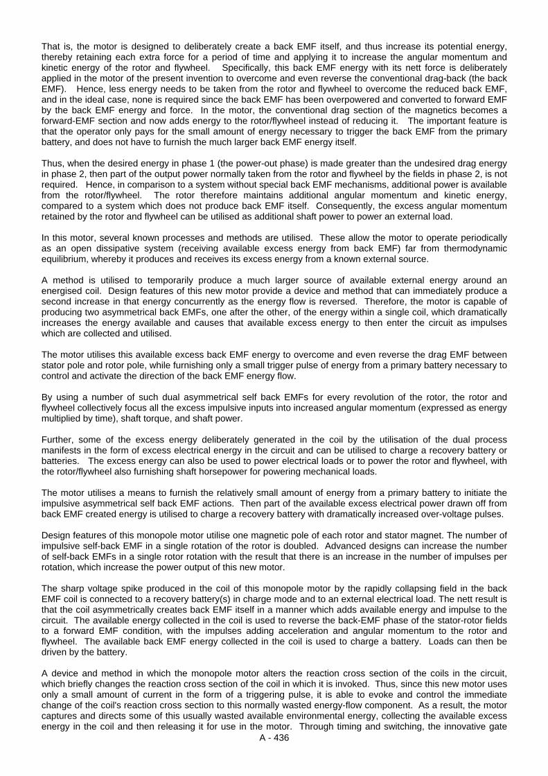
A - 436
That is, the motor is designed to deliberately create a back EMF itself, and thus increase its potential energy, thereby retaining each extra force for a period of time and applying it to increase the angular momentum and kinetic energy of the rotor and flywheel. Specifically, this back EMF energy with its nett force is deliberately applied in the motor of the present invention to overcome and even reverse the conventional drag-back (the back EMF). Hence, less energy needs to be taken from the rotor and flywheel to overcome the reduced back EMF, and in the ideal case, none is required since the back EMF has been overpowered and converted to forward EMF by the back EMF energy and force. In the motor, the conventional drag section of the magnetics becomes a forward-EMF section and now adds energy to the rotor/flywheel instead of reducing it. The important feature is that the operator only pays for the small amount of energy necessary to trigger the back EMF from the primary battery, and does not have to furnish the much larger back EMF energy itself. Thus, when the desired energy in phase 1 (the power-out phase) is made greater than the undesired drag energy in phase 2, then part of the output power normally taken from the rotor and flywheel by the fields in phase 2, is not required. Hence, in comparison to a system without special back EMF mechanisms, additional power is available from the rotor/flywheel. The rotor therefore maintains additional angular momentum and kinetic energy, compared to a system which does not produce back EMF itself. Consequently, the excess angular momentum retained by the rotor and flywheel can be utilised as additional shaft power to power an external load. In this motor, several known processes and methods are utilised. These allow the motor to operate periodically as an open dissipative system (receiving available excess energy from back EMF) far from thermodynamic equilibrium, whereby it produces and receives its excess energy from a known external source. A method is utilised to temporarily produce a much larger source of available external energy around an energised coil. Design features of this new motor provide a device and method that can immediately produce a second increase in that energy concurrently as the energy flow is reversed. Therefore, the motor is capable of producing two asymmetrical back EMFs, one after the other, of the energy within a single coil, which dramatically increases the energy available and causes that available excess energy to then enter the circuit as impulses which are collected and utilised. The motor utilises this available excess back EMF energy to overcome and even reverse the drag EMF between stator pole and rotor pole, while furnishing only a small trigger pulse of energy from a primary battery necessary to control and activate the direction of the back EMF energy flow. By using a number of such dual asymmetrical self back EMFs for every revolution of the rotor, the rotor and flywheel collectively focus all the excess impulsive inputs into increased angular momentum (expressed as energy multiplied by time), shaft torque, and shaft power. Further, some of the excess energy deliberately generated in the coil by the utilisation of the dual process manifests in the form of excess electrical energy in the circuit and can be utilised to charge a recovery battery or batteries. The excess energy can also be used to power electrical loads or to power the rotor and flywheel, with the rotor/flywheel also furnishing shaft horsepower for powering mechanical loads. The motor utilises a means to furnish the relatively small amount of energy from a primary battery to initiate the impulsive asymmetrical self back EMF actions. Then part of the available excess electrical power drawn off from back EMF created energy is utilised to charge a recovery battery with dramatically increased over-voltage pulses. Design features of this monopole motor utilise one magnetic pole of each rotor and stator magnet. The number of impulsive self-back EMF in a single rotation of the rotor is doubled. Advanced designs can increase the number of self-back EMFs in a single rotor rotation with the result that there is an increase in the number of impulses per rotation, which increase the power output of this new motor. The sharp voltage spike produced in the coil of this monopole motor by the rapidly collapsing field in the back EMF coil is connected to a recovery battery(s) in charge mode and to an external electrical load. The nett result is that the coil asymmetrically creates back EMF itself in a manner which adds available energy and impulse to the circuit. The available energy collected in the coil is used to reverse the back-EMF phase of the stator-rotor fields to a forward EMF condition, with the impulses adding acceleration and angular momentum to the rotor and flywheel. The available back EMF energy collected in the coil is used to charge a battery. Loads can then be driven by the battery. A device and method in which the monopole motor alters the reaction cross section of the coils in the circuit, which briefly changes the reaction cross section of the coil in which it is invoked. Thus, since this new motor uses only a small amount of current in the form of a triggering pulse, it is able to evoke and control the immediate change of the coil's reaction cross section to this normally wasted energy-flow component. As a result, the motor captures and directs some of this usually wasted available environmental energy, collecting the available excess energy in the coil and then releasing it for use in the motor. Through timing and switching, the innovative gate
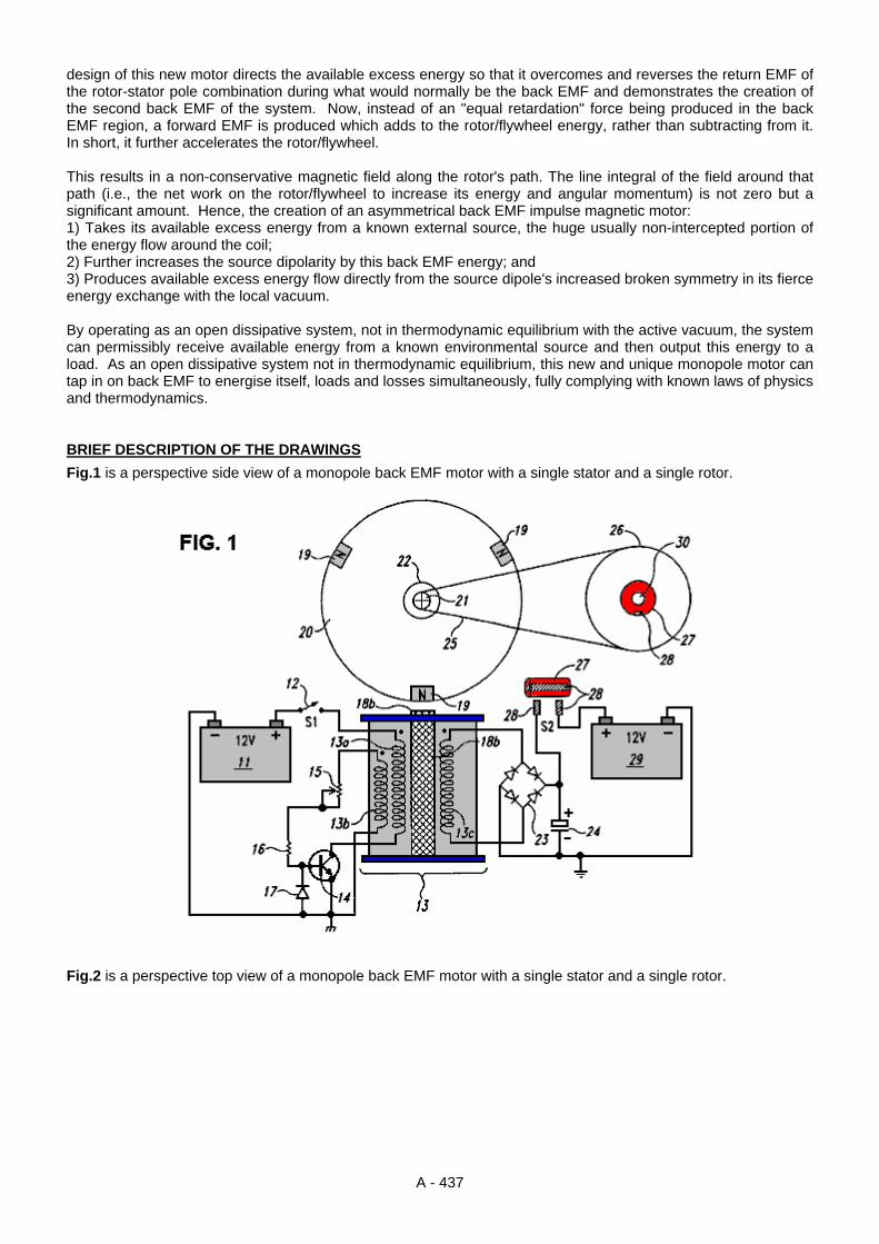
A - 437
design of this new motor directs the available excess energy so that it overcomes and reverses the return EMF of the rotor-stator pole combination during what would normally be the back EMF and demonstrates the creation of the second back EMF of the system. Now, instead of an "equal retardation" force being produced in the back EMF region, a forward EMF is produced which adds to the rotor/flywheel energy, rather than subtracting from it. In short, it further accelerates the rotor/flywheel. This results in a non-conservative magnetic field along the rotor's path. The line integral of the field around that path (i.e., the net work on the rotor/flywheel to increase its energy and angular momentum) is not zero but a significant amount. Hence, the creation of an asymmetrical back EMF impulse magnetic motor: 1) Takes its available excess energy from a known external source, the huge usually non-intercepted portion of the energy flow around the coil; 2) Further increases the source dipolarity by this back EMF energy; and 3) Produces available excess energy flow directly from the source dipole's increased broken symmetry in its fierce energy exchange with the local vacuum. By operating as an open dissipative system, not in thermodynamic equilibrium with the active vacuum, the system can permissibly receive available energy from a known environmental source and then output this energy to a load. As an open dissipative system not in thermodynamic equilibrium, this new and unique monopole motor can tap in on back EMF to energise itself, loads and losses simultaneously, fully complying with known laws of physics and thermodynamics. BRIEF DESCRIPTION OF THE DRAWINGS Fig.1 is a perspective side view of a monopole back EMF motor with a single stator and a single rotor.
Fig.2 is a perspective top view of a monopole back EMF motor with a single stator and a single rotor.
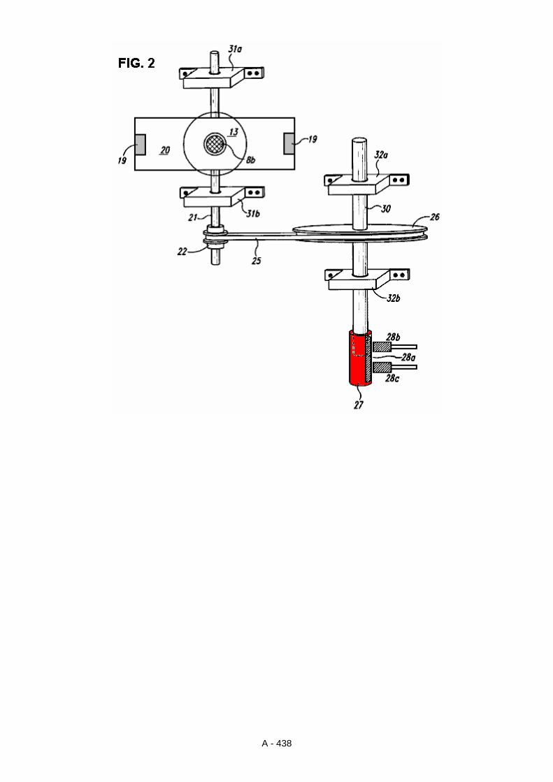
A - 438

A - 439
Fig.3 is a block diagram demonstrating the circuitry for a monopole back EMF motor.
. DETAILED DESCRIPTION OF THE INVENTION An embodiment of the present invention is a device and method for a monopole back EMF electromagnetic motor. As described in the Summary of the Invention, this monopole motor conforms to all applicable electrodynamic laws of physics and is in harmony with the law of the conservation of energy, the laws of electromagnetism and other related natural laws of physics. The monopole back EMF electromagnetic motor comprises a combination of elements and circuitry to capture available energy (back EMF) in a recovery element, such as a capacitor, from output coils. The available stored energy in the recovery element is used to charge a recovery battery. As a starting point, an arbitrary method in describing this device will be employed, namely, the flow of electrical energy and mechanical forces will be tracked from the energy's inception at the primary battery to its final storage in the recovery battery.
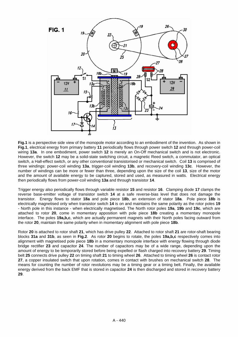
A - 440
Fig.1 is a perspective side view of the monopole motor according to an embodiment of the invention. As shown in Fig.1, electrical energy from primary battery 11 periodically flows through power switch 12 and through power-coil wiring 13a. In one embodiment, power switch 12 is merely an On-Off mechanical switch and is not electronic. However, the switch 12 may be a solid-state switching circuit, a magnetic Reed switch, a commutator, an optical switch, a Hall-effect switch, or any other conventional transistorised or mechanical switch. Coil 13 is comprised of three windings: power-coil winding 13a, trigger-coil winding 13b, and recovery-coil winding 13c. However, the number of windings can be more or fewer than three, depending upon the size of the coil 13, size of the motor and the amount of available energy to be captured, stored and used, as measured in watts. Electrical energy then periodically flows from power-coil winding 13a and through transistor 14. Trigger energy also periodically flows through variable resistor 15 and resistor 16. Clamping diode 17 clamps the reverse base-emitter voltage of transistor switch 14 at a safe reverse-bias level that does not damage the transistor. Energy flows to stator 18a and pole piece 18b, an extension of stator 18a. Pole piece 18b is electrically magnetised only when transistor switch 14 is on and maintains the same polarity as the rotor poles 19 - North pole in this instance - when electrically magnetised. The North rotor poles 19a, 19b and 19c, which are attached to rotor 20, come in momentary apposition with pole piece 18b creating a momentary monopole interface. The poles 19a,b,c, which are actually permanent magnets with their North poles facing outward from the rotor 20, maintain the same polarity when in momentary alignment with pole piece 18b. Rotor 20 is attached to rotor shaft 21, which has drive pulley 22. Attached to rotor shaft 21 are rotor-shaft bearing blocks 31a and 31b, as seen in Fig.2. As rotor 20 begins to rotate, the poles 19a,b,c respectively comes into alignment with magnetised pole piece 18b in a momentary monopole interface with energy flowing through diode bridge rectifier 23 and capacitor 24. The number of capacitors may be of a wide range, depending upon the amount of energy to be temporarily stored before being expelled or flash charged into recovery battery 29. Timing belt 25 connects drive pulley 22 on timing shaft 21 to timing wheel 26. Attached to timing wheel 26 is contact rotor 27, a copper insulated switch that upon rotation, comes in contact with brushes on mechanical switch 28. The means for counting the number of rotor revolutions may be a timing gear or a timing belt. Finally, the available energy derived from the back EMF that is stored in capacitor 24 is then discharged and stored in recovery battery 29.

A - 441
Fig.2 is a mechanical perspective top view of the monopole motor of the instant invention without electrical circuitry. Stator 18a consists of coil 13, which is comprised of three separate coil windings: power-coil winding 13a, trigger-coil winding 13b and recovery-coil winding 13c. Pole piece 18b is at the end of stator 18a. As rotor 20, (which is attached to rotor shaft 21) rotates, each pole 19 respectively comes in a momentary monopole interface with pole piece 18b. The polarity of pole piece 18b is constant when electrically magnetised. Rotor shaft 21 has rotor shaft bearing blocks 31a,b attached to it for stabilisation of rotor shaft 21. Attached to rotor shaft 21 is drive pulley 22 with timing belt 25 engaged with it. Another means for timing may be a timing gear. Timing belt 25 engages with timing wheel 26 at its other end. Timing wheel 26 is attached to timing shaft 30. Shaft 30 is stabilised with timing shaft bearing blocks 32a,b. Attached to one end of timing shaft 30 is contact rotor 27 with brush 28a, which, upon rotation of the timing shaft, comes into momentary contact with brushes 28b,c. Fig.3 is a block diagram detailing the circuitry of the monopole motor. Block 40 represents primary battery 11 with energy flowing to coil block 41, which represents coil windings 13a,b,c. From coil block 41 energy flows into three directions: to trigger-circuit block 42, transistor-circuit block 43, and rectifier-circuit block 44. Energy flows from rectifier-block 44 to storage-capacitor block 45 with energy flowing from block 45 to both recovery-battery block 46 and rotor-switch block 47. Referring to Fig.1, the operation of the motor is described according to an embodiment of the invention. For purpose of explanation, assume that the rotor 20 is initially not moving, and one of the poles 19 is in the three o'clock position.
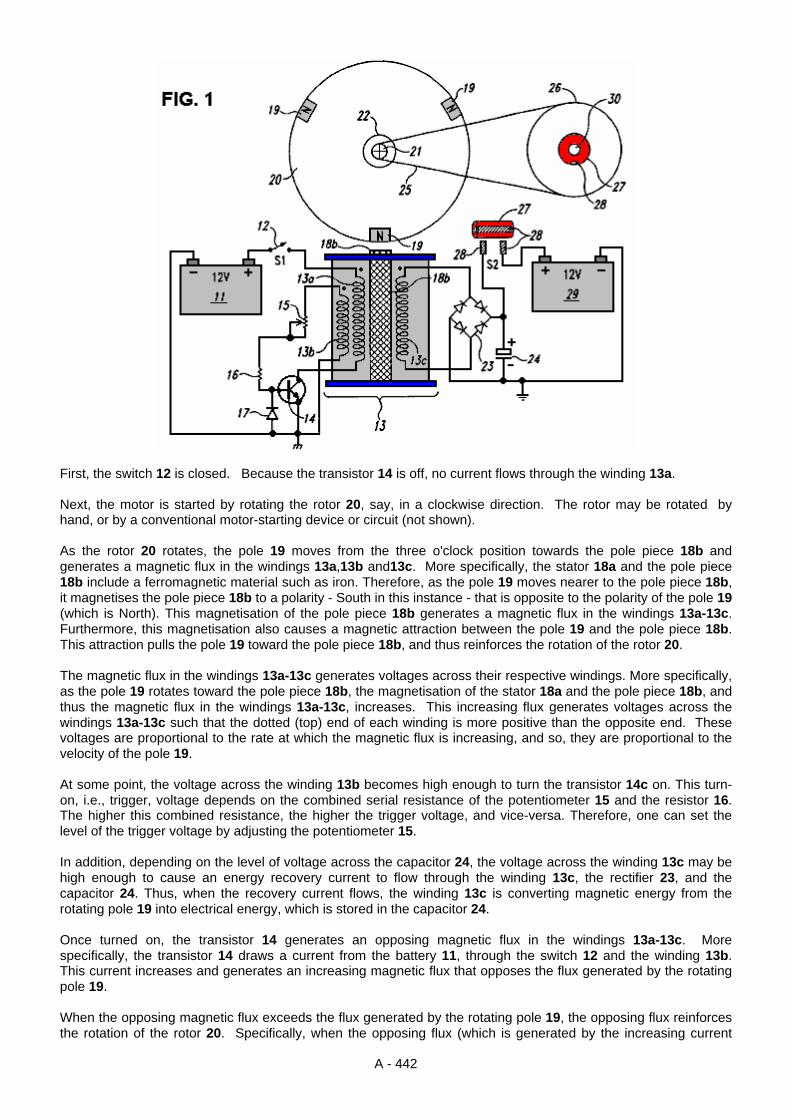
A - 442
First, the switch 12 is closed. Because the transistor 14 is off, no current flows through the winding 13a. Next, the motor is started by rotating the rotor 20, say, in a clockwise direction. The rotor may be rotated by hand, or by a conventional motor-starting device or circuit (not shown). As the rotor 20 rotates, the pole 19 moves from the three o'clock position towards the pole piece 18b and generates a magnetic flux in the windings 13a,13b and13c. More specifically, the stator 18a and the pole piece 18b include a ferromagnetic material such as iron. Therefore, as the pole 19 moves nearer to the pole piece 18b, it magnetises the pole piece 18b to a polarity - South in this instance - that is opposite to the polarity of the pole 19 (which is North). This magnetisation of the pole piece 18b generates a magnetic flux in the windings 13a-13c. Furthermore, this magnetisation also causes a magnetic attraction between the pole 19 and the pole piece 18b. This attraction pulls the pole 19 toward the pole piece 18b, and thus reinforces the rotation of the rotor 20. The magnetic flux in the windings 13a-13c generates voltages across their respective windings. More specifically, as the pole 19 rotates toward the pole piece 18b, the magnetisation of the stator 18a and the pole piece 18b, and thus the magnetic flux in the windings 13a-13c, increases. This increasing flux generates voltages across the windings 13a-13c such that the dotted (top) end of each winding is more positive than the opposite end. These voltages are proportional to the rate at which the magnetic flux is increasing, and so, they are proportional to the velocity of the pole 19. At some point, the voltage across the winding 13b becomes high enough to turn the transistor 14c on. This turn-on, i.e., trigger, voltage depends on the combined serial resistance of the potentiometer 15 and the resistor 16. The higher this combined resistance, the higher the trigger voltage, and vice-versa. Therefore, one can set the level of the trigger voltage by adjusting the potentiometer 15. In addition, depending on the level of voltage across the capacitor 24, the voltage across the winding 13c may be high enough to cause an energy recovery current to flow through the winding 13c, the rectifier 23, and the capacitor 24. Thus, when the recovery current flows, the winding 13c is converting magnetic energy from the rotating pole 19 into electrical energy, which is stored in the capacitor 24. Once turned on, the transistor 14 generates an opposing magnetic flux in the windings 13a-13c. More specifically, the transistor 14 draws a current from the battery 11, through the switch 12 and the winding 13b. This current increases and generates an increasing magnetic flux that opposes the flux generated by the rotating pole 19. When the opposing magnetic flux exceeds the flux generated by the rotating pole 19, the opposing flux reinforces the rotation of the rotor 20. Specifically, when the opposing flux (which is generated by the increasing current
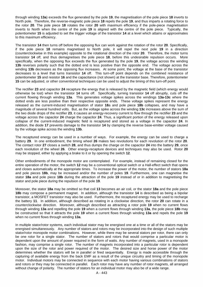
A - 443
through winding 13a) exceeds the flux generated by the pole 19, the magnetisation of the pole piece 18 inverts to North pole. Therefore, the reverse-magnetic pole piece 18 repels the pole 19, and thus imparts a rotating force to the rotor 20. The pole piece 18 rotates the rotor 20 with maximum efficiency if the pole-piece magnetisation inverts to North when the centre of the pole 19 is aligned with the centre of the pole piece. Typically, the potentiometer 15 is adjusted to set the trigger voltage of the transistor 14 at a level which attains or approximates to this maximum efficiency. The transistor 14 then turns off before the opposing flux can work against the rotation of the rotor 20. Specifically, if the pole piece 18 remains magnetised to North pole, it will repel the next pole 19 in a direction (counterclockwise in this example) opposite to the rotational direction of the rotor 20. Therefore, the motor turns transistor 14 off, and thus demagnetises the pole piece 18, before this undesirable repulsion occurs. More specifically, when the opposing flux exceeds the flux generated by the pole 19, the voltage across the winding 13b reverses polarity such that the dotted end is less positive than the opposite end. The voltage across the winding 13b decreases as the opposing flux increases. At some point, the voltage at the base of the transistor decreases to a level that turns transistor 14 off. This turn-off point depends on the combined resistance of potentiometer 15 and resistor 16 and the capacitance (not shown) at the transistor base. Therefore, potentiometer 15 can be adjusted, or other conventional techniques can be used to adjust the timing of this turn-off point. The rectifier 23 and capacitor 24 recapture the energy that is released by the magnetic field (which energy would otherwise be lost) when the transistor 14 turns off. Specifically, turning transistor 14 off abruptly, cuts off the current flowing through winding 13a. This generates voltage spikes across the windings 13a-13c where the dotted ends are less positive than their respective opposite ends. These voltage spikes represent the energy released as the current-induced magnetisation of stator 18a and pole piece 18b collapses, and may have a magnitude of several hundred volts. But, as the voltage spike across the winding 13c increases above the sum of the two diode drops of the rectifier 23, it causes an energy-recovery current to flow through the rectifier 23 and the voltage across the capacitor 24 charge the capacitor 24. Thus, a significant portion of the energy released upon collapse of the current-induced magnetic field is recaptured and stored as a voltage in the capacitor 24. In addition, the diode 17 prevents damage to the transistor 14 by clamping the reverse base-emitter voltage caused by the voltage spike across the winding 13b. The recaptured energy can be used in a number of ways. For example, the energy can be used to charge a battery 29. In one embodiment, the timing wheel 26 makes two revolutions for each revolution of the rotor 20. The contact rotor 27 closes a switch 28, and thus dumps the charge on the capacitor 24 into the battery 29, once each revolution of the wheel 26. Other energy-recapture devices and techniques may also be used. Rotor 20 may be stopped, either by applying a brake to it or by opening the switch 12. Other embodiments of the monopole motor are contemplated. For example, instead of remaining closed for the entire operation of the motor, the switch 12 may be a conventional optical switch or a Hall-effect switch that opens and closes automatically at the appropriate times. To increase the power of the motor, the number of stators 18a and pole pieces 18b, may be increased and/or the number of poles 19. Furthermore, one can magnetise the stator 18a and pole piece 18b during the attraction of the pole 19 instead of or in addition to magnetising the stator and pole piece during the repulsion of the pole 19. Moreover, the stator 18a may be omitted so that coil 13 becomes an air coil, or the stator 18a and the pole piece 18b may compose a permanent magnet. In addition, although the transistor 14 is described as being a bipolar transistor, a MOSFET transistor may also be used. Furthermore, the recaptured energy may be used to recharge the battery 11. In addition, although described as rotating in a clockwise direction, the rotor 20 can rotate in a counterclockwise direction. Moreover, although described as attracting a rotor pole 19 when no current flows through winding 13a and repelling the pole 19 when a current flows through winding 13a, the pole piece 18b may be constructed so that it attracts the pole 19 when a current flows through winding 13a and repels the pole 19 when no current flows through winding 13a. In multiple stator/rotor systems, each individual stator may be energised one at a time or all of the stators may be energised simultaneously. Any number of stators and rotors may be incorporated into the design of such multiple stator/rotor monopole motor combinations. However, while there may be several stators per rotor, there can only be one rotor for a single stator. The number of stators and rotors that would comprise a particular motor is dependent upon the amount of power required in the form of watts. Any number of magnets, used in a monopole fashion, may comprise a single rotor. The number of magnets incorporated into a particular rotor is dependent upon the size of the rotor and power required of the motor. The desired size and horse power of the motor determines whether the stators will be in parallel or fired sequentially. Energy is made accessible through the capturing of available energy from the back EMF as a result of the unique circuitry and timing of the monopole motor. Individual motors may be connected in sequence with each motor having various combinations of stators and rotors or they may be connected in parallel. Each rotor may have any number of rotor magnets, all arranged without change of polarity. The number of stators for an individual motor may also be of a wide range.
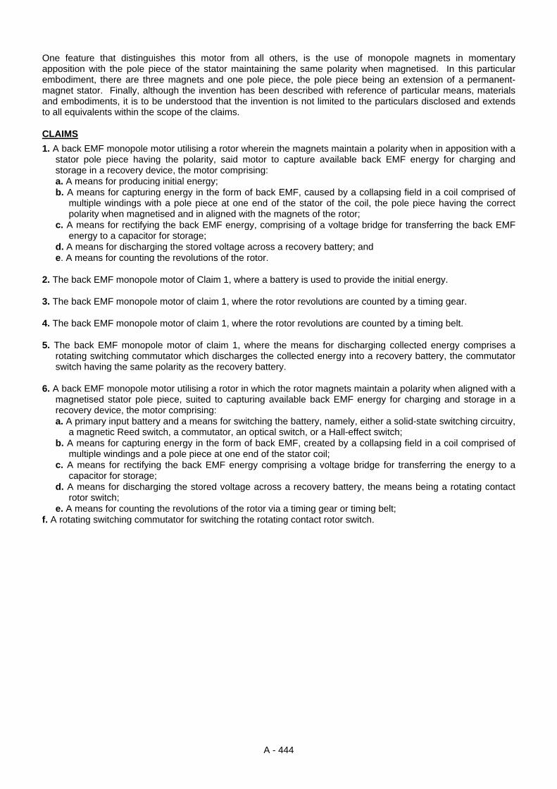
A - 444
One feature that distinguishes this motor from all others, is the use of monopole magnets in momentary apposition with the pole piece of the stator maintaining the same polarity when magnetised. In this particular embodiment, there are three magnets and one pole piece, the pole piece being an extension of a permanent-magnet stator. Finally, although the invention has been described with reference of particular means, materials and embodiments, it is to be understood that the invention is not limited to the particulars disclosed and extends to all equivalents within the scope of the claims. CLAIMS 1. A back EMF monopole motor utilising a rotor wherein the magnets maintain a polarity when in apposition with a
stator pole piece having the polarity, said motor to capture available back EMF energy for charging and storage in a recovery device, the motor comprising: a. A means for producing initial energy; b. A means for capturing energy in the form of back EMF, caused by a collapsing field in a coil comprised of
multiple windings with a pole piece at one end of the stator of the coil, the pole piece having the correct polarity when magnetised and in aligned with the magnets of the rotor;
c. A means for rectifying the back EMF energy, comprising of a voltage bridge for transferring the back EMF energy to a capacitor for storage;
d. A means for discharging the stored voltage across a recovery battery; and e. A means for counting the revolutions of the rotor.
2. The back EMF monopole motor of Claim 1, where a battery is used to provide the initial energy. 3. The back EMF monopole motor of claim 1, where the rotor revolutions are counted by a timing gear. 4. The back EMF monopole motor of claim 1, where the rotor revolutions are counted by a timing belt. 5. The back EMF monopole motor of claim 1, where the means for discharging collected energy comprises a
rotating switching commutator which discharges the collected energy into a recovery battery, the commutator switch having the same polarity as the recovery battery.
6. A back EMF monopole motor utilising a rotor in which the rotor magnets maintain a polarity when aligned with a
magnetised stator pole piece, suited to capturing available back EMF energy for charging and storage in a recovery device, the motor comprising: a. A primary input battery and a means for switching the battery, namely, either a solid-state switching circuitry,
a magnetic Reed switch, a commutator, an optical switch, or a Hall-effect switch; b. A means for capturing energy in the form of back EMF, created by a collapsing field in a coil comprised of
multiple windings and a pole piece at one end of the stator coil; c. A means for rectifying the back EMF energy comprising a voltage bridge for transferring the energy to a
capacitor for storage; d. A means for discharging the stored voltage across a recovery battery, the means being a rotating contact
rotor switch; e. A means for counting the revolutions of the rotor via a timing gear or timing belt;
f. A rotating switching commutator for switching the rotating contact rotor switch.
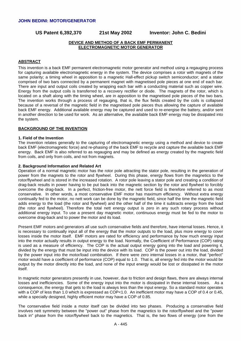
A - 445
JOHN BEDINI: MOTOR/GENERATOR
US Patent 6,392,370 21st May 2002 Inventor: John C. Bedini
DEVICE AND METHOD OF A BACK EMF PERMANENT ELECTROMAGNETIC MOTOR GENERATOR
ABSTRACT This invention is a back EMF permanent electromagnetic motor generator and method using a regauging process for capturing available electromagnetic energy in the system. The device comprises a rotor with magnets of the same polarity; a timing wheel in apposition to a magnetic Hall-effect pickup switch semiconductor; and a stator comprised of two bars connected by a permanent magnet with magnetised pole pieces at one end of each bar. There are input and output coils created by wrapping each bar with a conducting material such as copper wire. Energy from the output coils is transferred to a recovery rectifier or diode. The magnets of the rotor, which is located on a shaft along with the timing wheel, are in apposition to the magnetised pole pieces of the two bars. The invention works through a process of regauging, that is, the flux fields created by the coils is collapsed because of a reversal of the magnetic field in the magnetised pole pieces thus allowing the capture of available back EMF energy. Additional available energy may be captured and used to re-energise the battery, and/or sent in another direction to be used for work. As an alternative, the available back EMF energy may be dissipated into the system. BACKGROUND OF THE INVENTION 1. Field of the Invention The invention relates generally to the capturing of electromagnetic energy using a method and device to create back EMF (electromagnetic force) and re-phasing of the back EMF to recycle and capture the available back EMF energy. Back EMF is also referred to as regauging and may be defined as energy created by the magnetic field from coils, and only from coils, and not from magnets. 2. Background Information and Related Art Operation of a normal magnetic motor has the rotor pole attracting the stator pole, resulting in the generation of power from the magnets to the rotor and flywheel. During this phase, energy flows from the magnetics to the rotor/flywheel and is stored in the increased rotation. A rotor pole leaving a stator pole and creating a condition of drag-back results in power having to be put back into the magnetic section by the rotor and flywheel to forcibly overcome the drag-back. In a perfect, friction-free motor, the nett force field is therefore referred to as most conservative. In other words, a most conservative EMF motor has maximum efficiency. Without extra energy continually fed to the motor, no nett work can be done by the magnetic field, since half the time the magnetic field adds energy to the load (the rotor and flywheel) and the other half of the time it subtracts energy from the load (the rotor and flywheel). Therefore the total nett energy output is zero in any such rotary process without additional energy input. To use a present day magnetic motor, continuous energy must be fed to the motor to overcome drag-back and to power the motor and its load. Present EMF motors and generators all use such conservative fields and therefore, have internal losses. Hence, it is necessary to continually input all of the energy that the motor outputs to the load, plus more energy to cover losses inside the motor itself. EMF motors are rated for efficiency and performance by how much energy input into the motor actually results in output energy to the load. Normally, the Coefficient of Performance (COP) rating is used as a measure of efficiency. The COP is the actual output energy going into the load and powering it, divided by the energy that must be input into the device with its load. COP is the power out into the load, divided by the power input into the motor/load combination. If there were zero internal losses in a motor, that "perfect" motor would have a coefficient of performance (COP) equal to 1.0. That is, all energy fed into the motor would be output by the motor directly into the load, and none of the input energy would be lost or dissipated in the motor itself. In magnetic motor generators presently in use, however, due to friction and design flaws, there are always internal losses and inefficiencies. Some of the energy input into the motor is dissipated in these internal losses. As a consequence, the energy that gets to the load is always less than the input energy. So a standard motor operates with a COP of less than 1.0 which is expressed as COP<1.0. An inefficient motor may have a COP of 0.4 or 0.45, while a specially designed, highly efficient motor may have a COP of 0.85. The conservative field inside a motor itself can be divided into two phases. Producing a conservative field involves nett symmetry between the "power out" phase from the magnetics to the rotor/flywheel and the "power back in" phase from the rotor/flywheel back to the magnetics. That is, the two flows of energy (one from the
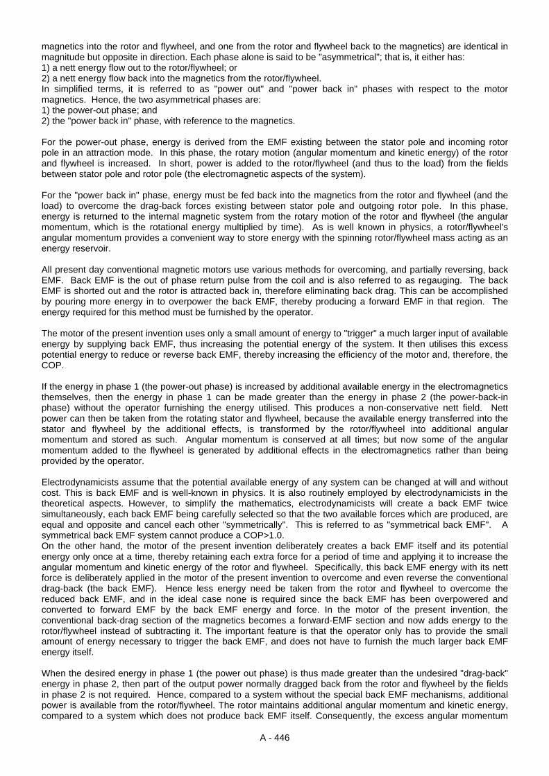
A - 446
magnetics into the rotor and flywheel, and one from the rotor and flywheel back to the magnetics) are identical in magnitude but opposite in direction. Each phase alone is said to be "asymmetrical"; that is, it either has: 1) a nett energy flow out to the rotor/flywheel; or 2) a nett energy flow back into the magnetics from the rotor/flywheel. In simplified terms, it is referred to as "power out" and "power back in" phases with respect to the motor magnetics. Hence, the two asymmetrical phases are: 1) the power-out phase; and 2) the "power back in" phase, with reference to the magnetics. For the power-out phase, energy is derived from the EMF existing between the stator pole and incoming rotor pole in an attraction mode. In this phase, the rotary motion (angular momentum and kinetic energy) of the rotor and flywheel is increased. In short, power is added to the rotor/flywheel (and thus to the load) from the fields between stator pole and rotor pole (the electromagnetic aspects of the system). For the "power back in" phase, energy must be fed back into the magnetics from the rotor and flywheel (and the load) to overcome the drag-back forces existing between stator pole and outgoing rotor pole. In this phase, energy is returned to the internal magnetic system from the rotary motion of the rotor and flywheel (the angular momentum, which is the rotational energy multiplied by time). As is well known in physics, a rotor/flywheel's angular momentum provides a convenient way to store energy with the spinning rotor/flywheel mass acting as an energy reservoir. All present day conventional magnetic motors use various methods for overcoming, and partially reversing, back EMF. Back EMF is the out of phase return pulse from the coil and is also referred to as regauging. The back EMF is shorted out and the rotor is attracted back in, therefore eliminating back drag. This can be accomplished by pouring more energy in to overpower the back EMF, thereby producing a forward EMF in that region. The energy required for this method must be furnished by the operator. The motor of the present invention uses only a small amount of energy to "trigger" a much larger input of available energy by supplying back EMF, thus increasing the potential energy of the system. It then utilises this excess potential energy to reduce or reverse back EMF, thereby increasing the efficiency of the motor and, therefore, the COP. If the energy in phase 1 (the power-out phase) is increased by additional available energy in the electromagnetics themselves, then the energy in phase 1 can be made greater than the energy in phase 2 (the power-back-in phase) without the operator furnishing the energy utilised. This produces a non-conservative nett field. Nett power can then be taken from the rotating stator and flywheel, because the available energy transferred into the stator and flywheel by the additional effects, is transformed by the rotor/flywheel into additional angular momentum and stored as such. Angular momentum is conserved at all times; but now some of the angular momentum added to the flywheel is generated by additional effects in the electromagnetics rather than being provided by the operator. Electrodynamicists assume that the potential available energy of any system can be changed at will and without cost. This is back EMF and is well-known in physics. It is also routinely employed by electrodynamicists in the theoretical aspects. However, to simplify the mathematics, electrodynamicists will create a back EMF twice simultaneously, each back EMF being carefully selected so that the two available forces which are produced, are equal and opposite and cancel each other "symmetrically". This is referred to as "symmetrical back EMF". A symmetrical back EMF system cannot produce a COP>1.0. On the other hand, the motor of the present invention deliberately creates a back EMF itself and its potential energy only once at a time, thereby retaining each extra force for a period of time and applying it to increase the angular momentum and kinetic energy of the rotor and flywheel. Specifically, this back EMF energy with its nett force is deliberately applied in the motor of the present invention to overcome and even reverse the conventional drag-back (the back EMF). Hence less energy need be taken from the rotor and flywheel to overcome the reduced back EMF, and in the ideal case none is required since the back EMF has been overpowered and converted to forward EMF by the back EMF energy and force. In the motor of the present invention, the conventional back-drag section of the magnetics becomes a forward-EMF section and now adds energy to the rotor/flywheel instead of subtracting it. The important feature is that the operator only has to provide the small amount of energy necessary to trigger the back EMF, and does not have to furnish the much larger back EMF energy itself. When the desired energy in phase 1 (the power out phase) is thus made greater than the undesired "drag-back" energy in phase 2, then part of the output power normally dragged back from the rotor and flywheel by the fields in phase 2 is not required. Hence, compared to a system without the special back EMF mechanisms, additional power is available from the rotor/flywheel. The rotor maintains additional angular momentum and kinetic energy, compared to a system which does not produce back EMF itself. Consequently, the excess angular momentum

A - 447
retained by the rotor and flywheel can be utilised as additional shaft power to power an external load connected to the shaft. A standard magnetic motor operates as the result of the motor being furnished with external energy input into the system by the operator to reduce phase 2 (power back into the magnetics from the rotor/flywheel) by any of several methods and mechanisms. The primary purpose of this external energy input into the system is to overcome the back EMF and also provide for the inevitable energy losses in the system. There is no input of energy separate from the operator input. Therefore, the COP of any standard magnetic motor is COP less than 1.0. The efficiency of a standard magnetic motor varies from less than 50% to a maximum of about 85%, and so has a COP<1.0. When nothing is done in the motor that will produce a reduction of the back EMF without the operator inputting all the energy for it, then for even a frictionless, ideal permanent magnet motor, the COP can never exceed 1.0. Until the introduction of the motor of the present invention, it has been standard universal practice that the operator must furnish all energy used to reduce the back EMF, provide for the internal losses, and power the load. It is therefore a common belief by the scientific community that an ideal (loss-less) permanent magnet motor cannot exceed a COP of 1.0. That is true, so long as the operator himself must furnish all the energy. Furthermore, since real permanent magnetic motors have real internal losses, some of the input energy is always lost in the motor itself, and that lost energy is not available for powering the rotor/flywheel and load. Hence a real permanent magnetic motor of the conventional kind will always have a COP<1.0. The common assumption that the COP of a motor is limited to less than 1.0 is not necessarily true, and that COP>1.0 is permitted without violating the laws of nature, physics, or thermodynamics. However, it can immediately be seen that any permanent magnet motor exhibiting a COP>1.0 must have some available energy input returning in the form of back EMF. A problem relates to how back EMF energy can be obtained from a circuit's external environment for the specific task of reducing the back-drag EMF without the operator having to supply any input of that excess energy. In short, the ultimate challenge is to find a way to cause the system to: 1) become an open dissipative system, that is, a system receiving available excess energy from its environment, in other words, from an external source; and 2) use that available excess energy to reduce the drag-back EMF between stator and rotor poles as the rotor pole is leaving the stator pole. If this objective can be accomplished, the system will be removed from thermodynamic equilibrium. Instead, it will be converted to a system out-of-thermodynamic equilibrium. Such a system is not obliged to obey classical equilibrium thermodynamics. Instead, an out-of-equilibrium thermodynamic system must obey the thermodynamics of open systems far from the established and well-known parameters of thermodynamic equilibrium. As is well known in the physics of thermodynamics, such open systems can permissibly: 1) self-order; 2) self-oscillate; 3) output more back EMF energy than energy input by the operator (the available excess back EMF energy is
received from an external source and some energy is input by the operator as well); 4) power itself as well as its loads and losses simultaneously (in that case, all the energy is received from the
available external source and there is no input energy from the operator); and 5) exhibit negative entropy, that is, produce an increase of energy that is available in the system, and that is
independent of the energy put into the system by the operator. As a definition, entropy roughly corresponds to the energy of a system that has become unavailable for use. Negative entropy corresponds to additional energy of a system that has become available for use. In the back EMF permanent magnet electromagnetic motor generator of the present invention, several known processes and methods are utilised which allow the invention to operate periodically as an open dissipative system (receiving available excess energy from back EMF) far from thermodynamic equilibrium, whereby it produces and receives its excess energy from a known external source. A method is utilised to temporarily produce a much larger source of available external energy around an energised coil. Then the unique design features of this new motor provides a method and mechanism that can immediately produce a second increase in that energy, concurrently as the energy flow is reversed. Therefore, the motor is capable of producing two asymmetrical back EMFs, one after the other, of the energy within a single coil, which dramatically increases the energy available and causes that available excess energy to then enter the circuit as an impulse, being collected and utilised.
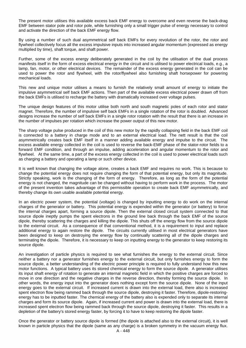
A - 448
The present motor utilises this available excess back EMF energy to overcome and even reverse the back-drag EMF between stator pole and rotor pole, while furnishing only a small trigger pulse of energy necessary to control and activate the direction of the back EMF energy flow. By using a number of such dual asymmetrical self back EMFs for every revolution of the rotor, the rotor and flywheel collectively focus all the excess impulsive inputs into increased angular momentum (expressed as energy multiplied by time), shaft torque, and shaft power. Further, some of the excess energy deliberately generated in the coil by the utilisation of the dual process manifests itself in the form of excess electrical energy in the circuit and is utilised to power electrical loads, e.g., a lamp, fan, motor, or other electrical devices. The remainder of the excess energy generated in the coil can be used to power the rotor and flywheel, with the rotor/flywheel also furnishing shaft horsepower for powering mechanical loads. This new and unique motor utilises a means to furnish the relatively small amount of energy to initiate the impulsive asymmetrical self back EMF actions. Then part of the available excess electrical power drawn off from the back EMFs is utilised to recharge the battery with dramatically increased over voltage pulses. The unique design features of this motor utilise both north and south magnetic poles of each rotor and stator magnet. Therefore, the number of impulsive self back EMFs in a single rotation of the rotor is doubled. Advanced designs increase the number of self back EMFs in a single rotor rotation with the result that there is an increase in the number of impulses per rotation which increase the power output of this new motor. The sharp voltage pulse produced in the coil of this new motor by the rapidly collapsing field in the back EMF coil is connected to a battery in charge mode and to an external electrical load. The nett result is that the coil asymmetrically creates back EMF itself in a manner adding available energy and impulse to the circuit. The excess available energy collected in the coil is used to reverse the back-EMF phase of the stator-rotor fields to a forward EMF condition, and through an impulse, adding acceleration and angular momentum to the rotor and flywheel. At the same time, a part of the excess energy collected in the coil is used to power electrical loads such as charging a battery and operating a lamp or such other device. It is well known that changing the voltage alone, creates a back EMF and requires no work. This is because to change the potential energy does not require changing the form of that potential energy, but only its magnitude. Strictly speaking, work is the changing of the form of energy. Therefore, as long as the form of the potential energy is not changed, the magnitude can be changed without having to perform work in the process. The motor of the present invention takes advantage of this permissible operation to create back EMF asymmetrically, and thereby change its own usable available potential energy. In an electric power system, the potential (voltage) is changed by inputting energy to do work on the internal charges of the generator or battery. This potential energy is expended within the generator (or battery) to force the internal charges apart, forming a source dipole. Then the external closed circuit system connected to that source dipole ineptly pumps the spent electrons in the ground line back through the back EMF of the source dipole, thereby scattering the charges and killing the dipole. This shuts off the energy flow from the source dipole to the external circuit. As a consequence of that conventional method, it is a requirement to input and replace additional energy to again restore the dipole. The circuits currently utilised in most electrical generators have been designed to keep on destroying the energy flow by continually scattering all of the dipole charges and terminating the dipole. Therefore, it is necessary to keep on inputting energy to the generator to keep restoring its source dipole. An investigation of particle physics is required to see what furnishes the energy to the external circuit. Since neither a battery nor a generator furnishes energy to the external circuit, but only furnishes energy to form the source dipole, a better understanding of the electric power principle is required to fully understand how this new motor functions. A typical battery uses its stored chemical energy to form the source dipole. A generator utilises its input shaft energy of rotation to generate an internal magnetic field in which the positive charges are forced to move in one direction and the negative charges in the reverse direction, thereby forming the source dipole. In other words, the energy input into the generator does nothing except form the source dipole. None of the input energy goes to the external circuit. If increased current is drawn into the external load, there also is increased spent electron flow being rammed back through the source dipole, destroying it faster. Therefore, dipole-restoring-energy has to be inputted faster. The chemical energy of the battery also is expended only to separate its internal charges and form its source dipole. Again, if increased current and power is drawn into the external load, there is increased spent electron flow being rammed back through the source dipole, destroying it faster. This results in a depletion of the battery's stored energy faster, by forcing it to have to keep restoring the dipole faster. Once the generator or battery source dipole is formed (the dipole is attached also to the external circuit), it is well known in particle physics that the dipole (same as any charge) is a broken symmetry in the vacuum energy flux.
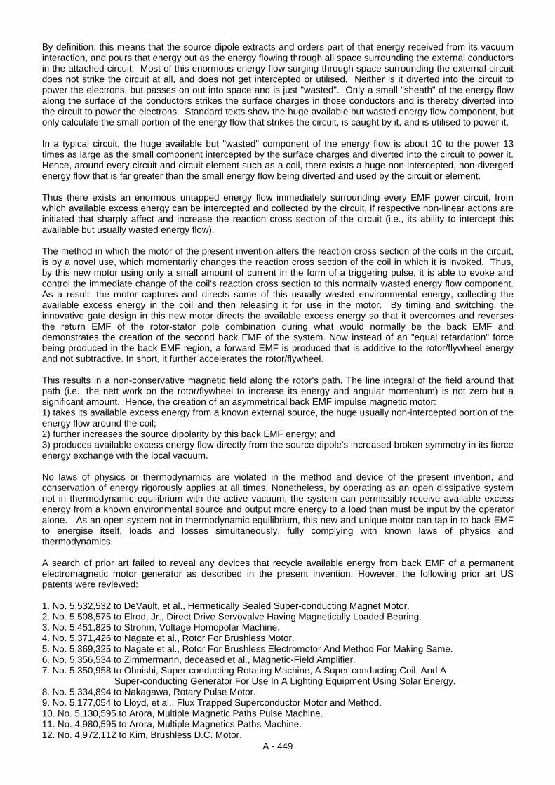
A - 449
By definition, this means that the source dipole extracts and orders part of that energy received from its vacuum interaction, and pours that energy out as the energy flowing through all space surrounding the external conductors in the attached circuit. Most of this enormous energy flow surging through space surrounding the external circuit does not strike the circuit at all, and does not get intercepted or utilised. Neither is it diverted into the circuit to power the electrons, but passes on out into space and is just "wasted". Only a small "sheath" of the energy flow along the surface of the conductors strikes the surface charges in those conductors and is thereby diverted into the circuit to power the electrons. Standard texts show the huge available but wasted energy flow component, but only calculate the small portion of the energy flow that strikes the circuit, is caught by it, and is utilised to power it. In a typical circuit, the huge available but "wasted" component of the energy flow is about 10 to the power 13 times as large as the small component intercepted by the surface charges and diverted into the circuit to power it. Hence, around every circuit and circuit element such as a coil, there exists a huge non-intercepted, non-diverged energy flow that is far greater than the small energy flow being diverted and used by the circuit or element. Thus there exists an enormous untapped energy flow immediately surrounding every EMF power circuit, from which available excess energy can be intercepted and collected by the circuit, if respective non-linear actions are initiated that sharply affect and increase the reaction cross section of the circuit (i.e., its ability to intercept this available but usually wasted energy flow). The method in which the motor of the present invention alters the reaction cross section of the coils in the circuit, is by a novel use, which momentarily changes the reaction cross section of the coil in which it is invoked. Thus, by this new motor using only a small amount of current in the form of a triggering pulse, it is able to evoke and control the immediate change of the coil's reaction cross section to this normally wasted energy flow component. As a result, the motor captures and directs some of this usually wasted environmental energy, collecting the available excess energy in the coil and then releasing it for use in the motor. By timing and switching, the innovative gate design in this new motor directs the available excess energy so that it overcomes and reverses the return EMF of the rotor-stator pole combination during what would normally be the back EMF and demonstrates the creation of the second back EMF of the system. Now instead of an "equal retardation" force being produced in the back EMF region, a forward EMF is produced that is additive to the rotor/flywheel energy and not subtractive. In short, it further accelerates the rotor/flywheel. This results in a non-conservative magnetic field along the rotor's path. The line integral of the field around that path (i.e., the nett work on the rotor/flywheel to increase its energy and angular momentum) is not zero but a significant amount. Hence, the creation of an asymmetrical back EMF impulse magnetic motor: 1) takes its available excess energy from a known external source, the huge usually non-intercepted portion of the energy flow around the coil; 2) further increases the source dipolarity by this back EMF energy; and 3) produces available excess energy flow directly from the source dipole's increased broken symmetry in its fierce energy exchange with the local vacuum. No laws of physics or thermodynamics are violated in the method and device of the present invention, and conservation of energy rigorously applies at all times. Nonetheless, by operating as an open dissipative system not in thermodynamic equilibrium with the active vacuum, the system can permissibly receive available excess energy from a known environmental source and output more energy to a load than must be input by the operator alone. As an open system not in thermodynamic equilibrium, this new and unique motor can tap in to back EMF to energise itself, loads and losses simultaneously, fully complying with known laws of physics and thermodynamics. A search of prior art failed to reveal any devices that recycle available energy from back EMF of a permanent electromagnetic motor generator as described in the present invention. However, the following prior art US patents were reviewed: 1. No. 5,532,532 to DeVault, et al., Hermetically Sealed Super-conducting Magnet Motor. 2. No. 5,508,575 to Elrod, Jr., Direct Drive Servovalve Having Magnetically Loaded Bearing. 3. No. 5,451,825 to Strohm, Voltage Homopolar Machine. 4. No. 5,371,426 to Nagate et al., Rotor For Brushless Motor. 5. No. 5,369,325 to Nagate et al., Rotor For Brushless Electromotor And Method For Making Same. 6. No. 5,356,534 to Zimmermann, deceased et al., Magnetic-Field Amplifier. 7. No. 5,350,958 to Ohnishi, Super-conducting Rotating Machine, A Super-conducting Coil, And A Super-conducting Generator For Use In A Lighting Equipment Using Solar Energy. 8. No. 5,334,894 to Nakagawa, Rotary Pulse Motor. 9. No. 5,177,054 to Lloyd, et al., Flux Trapped Superconductor Motor and Method. 10. No. 5,130,595 to Arora, Multiple Magnetic Paths Pulse Machine. 11. No. 4,980,595 to Arora, Multiple Magnetics Paths Machine. 12. No. 4,972,112 to Kim, Brushless D.C. Motor.
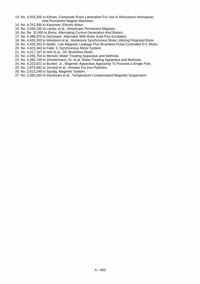
A - 450
13. No. 4,916,346 to Kliman, Composite Rotor Lamination For Use In Reluctance Homopolar, And Permanent Magnet Machines. 14. No. 4,761,590 to Kaszman, Electric Motor. 15. No. 4,536,230 to Landa, et al., Anisotropic Permanent Magnets. 16. No. Re. 31,950 to Binns, Alternating Current Generators And Motors. 17. No. 4,488,075 to DeCesare, Alternator With Rotor Axial Flux Excitation. 18. No. 4,433,260 to Weisbord et al., Hysteresis Synchronous Motor Utilizing Polarized Rotor. 19. No. 4,429,263 to Muller, Low Magnetic Leakage Flux Brushless Pulse Controlled D-C Motor. 20. No. 4,423,343 to Field, II, Synchronous Motor System. 21. No. 4,417,167 to Ishii et al., DC Brushless Motor. 22. No. 4,265,754 to Menold, Water Treating Apparatus and Methods. 23. No. 4,265,746 to Zimmermann, Sr. et al. Water Treating Apparatus and Methods. 24. No. 4,222,021 to Bunker, Jr., Magnetic Apparatus Appearing To Possess a Single Pole. 25. No. 2,974,981 to Vervest et al., Arrester For Iron Particles. 26. No. 2,613,246 to Spodig, Magnetic System. 27. No. 2,560,260 to Sturtevant et al., Temperature Compensated Magnetic Suspension.
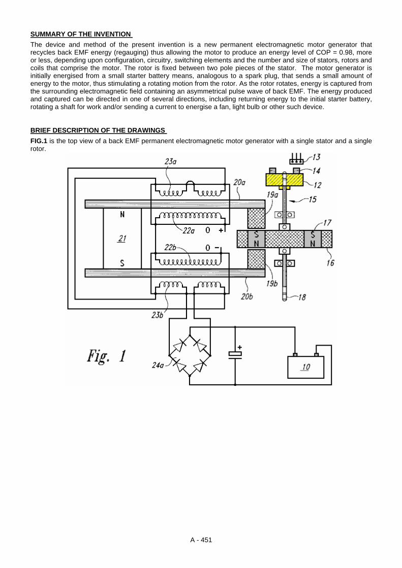
A - 451
SUMMARY OF THE INVENTION The device and method of the present invention is a new permanent electromagnetic motor generator that recycles back EMF energy (regauging) thus allowing the motor to produce an energy level of COP = 0.98, more or less, depending upon configuration, circuitry, switching elements and the number and size of stators, rotors and coils that comprise the motor. The rotor is fixed between two pole pieces of the stator. The motor generator is initially energised from a small starter battery means, analogous to a spark plug, that sends a small amount of energy to the motor, thus stimulating a rotating motion from the rotor. As the rotor rotates, energy is captured from the surrounding electromagnetic field containing an asymmetrical pulse wave of back EMF. The energy produced and captured can be directed in one of several directions, including returning energy to the initial starter battery, rotating a shaft for work and/or sending a current to energise a fan, light bulb or other such device. BRIEF DESCRIPTION OF THE DRAWINGS FIG.1 is the top view of a back EMF permanent electromagnetic motor generator with a single stator and a single rotor.
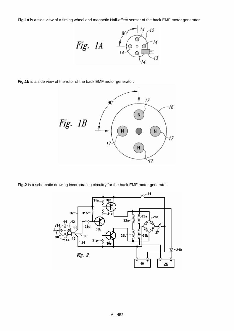
A - 452
Fig.1a is a side view of a timing wheel and magnetic Hall-effect sensor of the back EMF motor generator.
Fig.1b is a side view of the rotor of the back EMF motor generator.
Fig.2 is a schematic drawing incorporating circuitry for the back EMF motor generator.
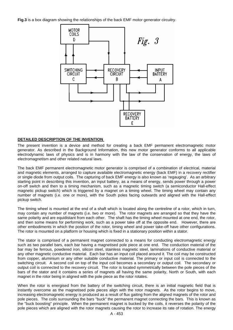
A - 453
Fig.3 is a box diagram showing the relationships of the back EMF motor generator circuitry.
DETAILED DESCRIPTION OF THE INVENTION The present invention is a device and method for creating a back EMF permanent electromagnetic motor generator. As described in the Background Information, this new motor generator conforms to all applicable electrodynamic laws of physics and is in harmony with the law of the conservation of energy, the laws of electromagnetism and other related natural laws. The back EMF permanent electromagnetic motor generator is comprised of a combination of electrical, material and magnetic elements, arranged to capture available electromagnetic energy (back EMF) in a recovery rectifier or single diode from output coils. The capturing of back EMF energy is also known as ‘regauging’. As an arbitrary starting point in describing this invention, an input battery, as a means of energy, sends power through a power on-off switch and then to a timing mechanism, such as a magnetic timing switch (a semiconductor Hall-effect magnetic pickup switch) which is triggered by a magnet on a timing wheel. The timing wheel may contain any number of magnets (i.e. one or more), with the South poles facing outwards and aligned with the Hall-effect pickup switch. The timing wheel is mounted at the end of a shaft which is located along the centreline of a rotor, which in turn, may contain any number of magnets (i.e. two or more). The rotor magnets are arranged so that they have the same polarity and are equidistant from each other. The shaft has the timing wheel mounted at one end, the rotor, and then some means for performing work, such as a power take off at the opposite end. However, there are other embodiments in which the position of the rotor, timing wheel and power take-off have other configurations. The rotor is mounted on a platform or housing which is fixed in a stationary position within a stator. The stator is comprised of a permanent magnet connected to a means for conducting electromagnetic energy such as two parallel bars, each bar having a magnetised pole piece at one end. The conduction material of the bar may be ferrous, powdered iron, silicon steel, stainless magnetic steel, laminations of conductive material or any other magnetic conductive material. Each bar has an input coil placed around it. The coil may be constructed from copper, aluminium or any other suitable conductive material. The primary or input coil is connected to the switching circuit. A second coil on top of the input coil becomes a secondary or output coil. The secondary or output coil is connected to the recovery circuit. The rotor is located symmetrically between the pole pieces of the bars of the stator and it contains a series of magnets all having the same polarity, North or South, with each magnet in the rotor being in aligned with the pole piece as the rotor rotates. When the rotor is energised from the battery of the switching circuit, there is an initial magnetic field that is instantly overcome as the magnetised pole pieces align with the rotor magnets. As the rotor begins to move, increasing electromagnetic energy is produced as a result of flux gaiting from the aligned magnets of the rotor and pole pieces. The coils surrounding the bars "buck" the permanent magnet connecting the bars. This is known as the "buck boosting" principle. When the permanent magnet is bucked by the coils, it reverses the polarity of the pole pieces which are aligned with the rotor magnets causing the rotor to increase its rate of rotation. The energy
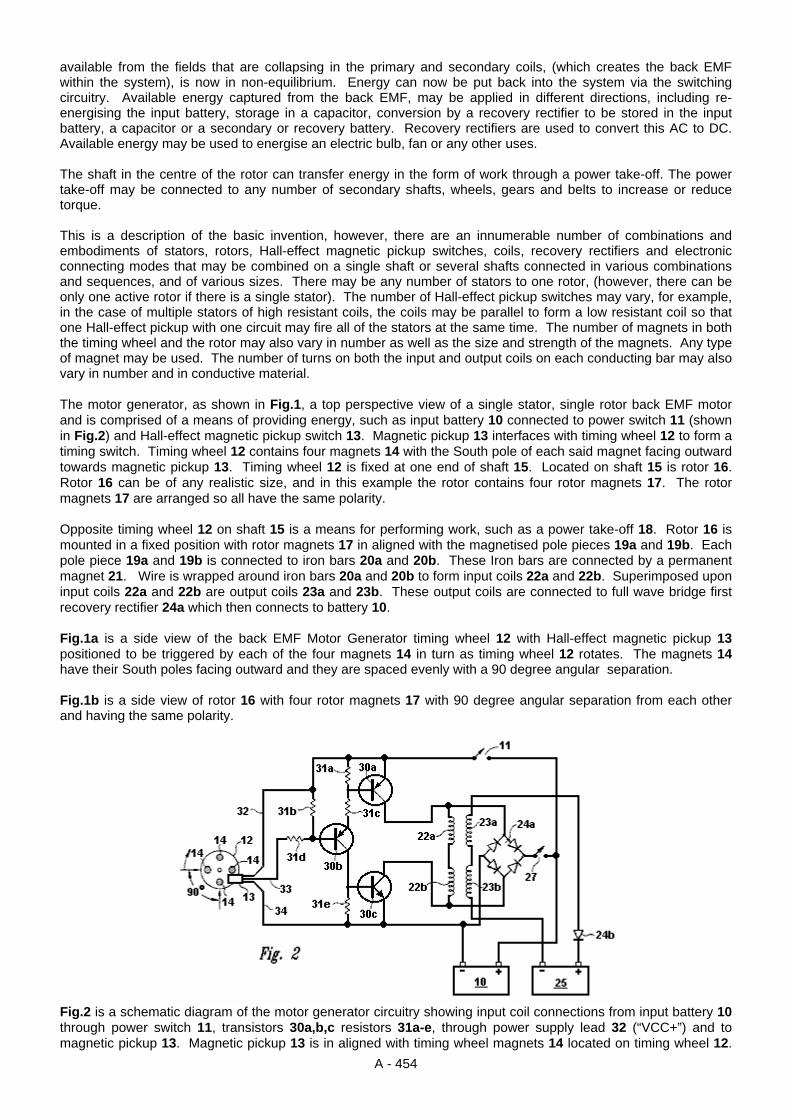
A - 454
available from the fields that are collapsing in the primary and secondary coils, (which creates the back EMF within the system), is now in non-equilibrium. Energy can now be put back into the system via the switching circuitry. Available energy captured from the back EMF, may be applied in different directions, including re-energising the input battery, storage in a capacitor, conversion by a recovery rectifier to be stored in the input battery, a capacitor or a secondary or recovery battery. Recovery rectifiers are used to convert this AC to DC. Available energy may be used to energise an electric bulb, fan or any other uses. The shaft in the centre of the rotor can transfer energy in the form of work through a power take-off. The power take-off may be connected to any number of secondary shafts, wheels, gears and belts to increase or reduce torque. This is a description of the basic invention, however, there are an innumerable number of combinations and embodiments of stators, rotors, Hall-effect magnetic pickup switches, coils, recovery rectifiers and electronic connecting modes that may be combined on a single shaft or several shafts connected in various combinations and sequences, and of various sizes. There may be any number of stators to one rotor, (however, there can be only one active rotor if there is a single stator). The number of Hall-effect pickup switches may vary, for example, in the case of multiple stators of high resistant coils, the coils may be parallel to form a low resistant coil so that one Hall-effect pickup with one circuit may fire all of the stators at the same time. The number of magnets in both the timing wheel and the rotor may also vary in number as well as the size and strength of the magnets. Any type of magnet may be used. The number of turns on both the input and output coils on each conducting bar may also vary in number and in conductive material. The motor generator, as shown in Fig.1, a top perspective view of a single stator, single rotor back EMF motor and is comprised of a means of providing energy, such as input battery 10 connected to power switch 11 (shown in Fig.2) and Hall-effect magnetic pickup switch 13. Magnetic pickup 13 interfaces with timing wheel 12 to form a timing switch. Timing wheel 12 contains four magnets 14 with the South pole of each said magnet facing outward towards magnetic pickup 13. Timing wheel 12 is fixed at one end of shaft 15. Located on shaft 15 is rotor 16. Rotor 16 can be of any realistic size, and in this example the rotor contains four rotor magnets 17. The rotor magnets 17 are arranged so all have the same polarity. Opposite timing wheel 12 on shaft 15 is a means for performing work, such as a power take-off 18. Rotor 16 is mounted in a fixed position with rotor magnets 17 in aligned with the magnetised pole pieces 19a and 19b. Each pole piece 19a and 19b is connected to iron bars 20a and 20b. These Iron bars are connected by a permanent magnet 21. Wire is wrapped around iron bars 20a and 20b to form input coils 22a and 22b. Superimposed upon input coils 22a and 22b are output coils 23a and 23b. These output coils are connected to full wave bridge first recovery rectifier 24a which then connects to battery 10. Fig.1a is a side view of the back EMF Motor Generator timing wheel 12 with Hall-effect magnetic pickup 13 positioned to be triggered by each of the four magnets 14 in turn as timing wheel 12 rotates. The magnets 14 have their South poles facing outward and they are spaced evenly with a 90 degree angular separation. Fig.1b is a side view of rotor 16 with four rotor magnets 17 with 90 degree angular separation from each other and having the same polarity.
Fig.2 is a schematic diagram of the motor generator circuitry showing input coil connections from input battery 10 through power switch 11, transistors 30a,b,c resistors 31a-e, through power supply lead 32 (“VCC+”) and to magnetic pickup 13. Magnetic pickup 13 is in aligned with timing wheel magnets 14 located on timing wheel 12.

A - 455
Collector lead 33 and ground lead 34 carry the signals from magnetic pickup 13. When current is reversed, it flows through resistor 31e and transistor 30c to input battery 10. Input coils 22a,b send power to full wave bridge first recovery rectifier 24a which then sends power through switch recovery 27 back into the system, and/or to the input battery 10. Output coils 23a and 23b send power through single diode second recovery rectifier 24b to recovery battery 25. In this particular embodiment, the value and type number of the components are as follows: Hall-effect magnetic pickup switch 13 is a No. 3020; Transistor 30a is a 2N2955; Transistor 30b is an MPS8599; Transistor 30c is a 2N3055; Resistors 31a and 31b are 470 ohms Resistor 31b is 2.2 K ohms Resistor 31c is 220 ohms Resistor 31d is 1 K ohms Recovery rectifier 24a is a 10 Amp, 400 volts bridge rectifier. Fig.3 is a box diagram showing the flow of voltage from input battery A, through recovery circuit B, switching circuit C and motor coils D. Motor coils D send available back EMF energy through recovery circuit B, and then on to recovery battery E and input battery A. Available back EMF energy can also flow from switching circuit C to recovery circuit B. In multiple stator/rotor systems, each individual stator may be energised one at a time or all of the stators may be energised simultaneously. Any number of stators and rotors may be incorporated into the design of such multiple stator/rotor motor generator combinations. However, while there may be several stators per rotor, there can only be one rotor for a single stator. The number of stators and rotors that would comprise a particular motor generator is dependent upon the amount of power required in the form of watts. The desired size and horsepower of the motor determines whether the stators will be in parallel or fired sequentially by the magnetic Hall-effect pickup or pickups. The number of magnets incorporated into a particular rotor is dependent upon the size of the rotor and power required of the motor generator. In a multiple stator/rotor motor generator, the timing wheel may have one or more magnets, but must have one magnet Hall-effect pickup for each stator if the stators are not arranged in parallel. The back EMF energy is made available through the reversing of the polarity of the magnetised pole pieces thus collapsing the field around the coils and reversing the flow of energy to the recovery diodes, which are capturing the back EMF. Individual motors may be connected in sequence, with each motor having various combinations of stators and rotors, or they may be connected in parallel. Each rotor may have any number of magnets ranging from a minimum of 2 to maximum of 60. The number of stators for an individual motor may range from 1 to 60 with the number of conducting bars ranging from 2 to 120. What distinguishes this motor generator from all others is the presence of a permanent magnet connecting the two conducting bars which transfer magnetic energy through the pole pieces to the rotor, thereby attracting the rotor between the pole pieces. With the rotor attracted in between the two pole pieces, the coils switch the polarity of the magnetic field of the pole pieces so that the rotor is repelled out. Therefore there is no current and voltage being used to attract the rotor. The only current being used is the repulsion of the rotor between the two conductive bar pole pieces thereby requiring only a small amount of current to repel the rotor. This is known as ‘a regauging system’ and allows the capturing of available back EMF energy. Finally, although the invention has been described with reference of particular means, materials and embodiments, it is to be understood that the invention is not limited to the particulars disclosed and extends to all equivalents within the scope of the claims.
A - 456
JOHN BEDINI: BATTERY PULSE CHARGER
US Patent Application 2003/117111 26th June 2003 Inventor: John C. Bedini
DEVICE AND METHOD FOR PULSE-CHARGING A BATTERY
AND FOR DRIVING OTHER DEVICES WITH A PULSE This is a slightly reworded copy of this patent application which shows a method of pulse-charging a battery bank or powering a heater and/or a motor. John Bedini is an intuitive genius with very considerable practical ability, so any information coming from him should be considered most carefully. At the end of this document there is some additional information not found in the patent. ABSTRACT This two-phase solid-state battery charger can receive input energy from a variety of sources including AC current, a battery, a DC generator, a DC-to-DC inverter, solar cells or any other compatible source of input energy. Phase 1 is the charging phase and Phase 2 is the discharge phase, where a signal, or current, passes through a dual timing switch which independently controls two channels, thus producing the two phases. The dual timing switch is controlled by a logic chip, or pulse width modulator. A potential charge is allowed to build up in a capacitor bank. The capacitor bank is then disconnected from the energy input source and then a high voltage pulse is fed into the battery which is there to receive the charge. The momentary disconnection of the capacitor from the input energy source allows a free-floating potential charge in the capacitor. Once the capacitor has completed discharging the potential charge into the battery, the capacitor disconnects from the charging battery and re-connects to the energy source, thus completing the two-phase cycle. TECHNICAL FIELD This invention relates generally to a battery pulse-charger using a solid-state device and method where the current going to the battery is not constant. The signal or current is momentarily switch-interrupted as it flows through either the first channel, (the charging phase), or the second channel, (the discharging phase). This two-phase cycle alternates the signal in the two channels thereby allowing a potential charge in a capacitor to disconnect from its power source an instant before the capacitor discharges its stored potential energy into a battery set up to receive the capacitor's stored energy. The capacitor is then disconnected from the battery and re-connected to the power source upon completion of the discharge phase, thereby completing the charge-discharge cycle. The battery pulse-charger can also drive devices, such as a motor and a heating element, with pulses. BACKGROUND AND PRIOR ART Present day battery chargers use a constant charge current in their operation with no momentary disconnection of the signal or current as it flows either: (1) from a primary energy source to the charger; or (2) from the charger itself into a battery for receiving the charge. Some chargers are regulated to a constant current by any of several methods, while others are constant and are not regulated. There are no battery chargers currently in the art or available wherein there is a momentary signal or current disconnection between the primary energy source and the charger capacitors an instant before the capacitors discharge the stored potential energy into a battery receiving the pulse charge. Nor are there any chargers in the art that disconnect the charger from the battery receiving the charge when the charger capacitors receive energy from the primary source. The momentary current interruption allows the battery a short "rest period" and requires less energy from the primary energy source while putting more energy into the battery receiving the charge while requiring a shorter period of time to do it. SUMMARY OF THE INVENTION One aspect of the invention relates to a solid-state device and method for creating a pulse current to pulse-charge a battery or a bank of batteries in which a new and unique method is used to increase and preserve, for a longer period of time, the energy stored in the battery, as compared to constant-current battery chargers. The device uses a timed pulse to create a DC pulse waveform to be discharged into the battery receiving the charge. One embodiment of the Invention uses a means for dual switching such as a pulse-width modulator (PWM), for example, a logic chip SG3524N PWM, and a means for optical coupling to a bank of high-energy capacitors to
A - 457
store a timed initial pulse charge. This is the charge phase, or phase 1. The charged capacitor bank then discharges the stored high energy into the battery receiving the charge in timed pulses. Just prior to discharging the stored energy into the battery, the capacitor bank is momentarily disconnected from the power source, thus completing the charge phase, and thereby leaving the capacitor bank as a free-floating potential charge disconnected from the primary energy source to then be discharged into the battery. The transfer of energy from the capacitor bank to the battery completes the discharge phase, or phase 2. The two-phase cycle now repeats itself. This embodiment of the battery pulse-charger works by transferring energy from a source, such as an AC source, to an unfiltered DC source of high voltage to be stored in a capacitor or a capacitor bank. A switching regulator is set to a timed pulse, for example, a one second pulse that is 180 degrees out of phase for each set of switching functions. The first function is to build the charge in the capacitor bank from the primary energy source; the second function is to disconnect the power source from the capacitor bank; the third function is to discharge the stored high voltage to the battery with a high voltage spike in a timed pulse, for example, a one second pulse; and the fourth function is to re-connect the capacitor bank to the primary energy source. The device operates through a two-channel on/off switching mechanism or a gauging/re-gauging function wherein the charger is disconnected from its primary energy source an instant before the pulse-charger discharges the high-energy pulse into the battery to be charged. As the primary charging switch closes, the secondary discharging switch opens, and vise-versa in timed pulses to complete the two phase cycle. The means for a power supply is varied with several options available as the primary energy source. For example, primary input energy may come from an AC source connected into the proper voltage (transformer); from an AC generator; from a primary input battery; from solar cells; from a DC-to-DC inverter; or from any other adaptable source of energy. If a transformer is the source of primary input energy, then it can be a standard rectifying transformer used in power supply applications or any other transformer applicable to the desired function. For example, it can be a 120-volt to 45-volt AC step-down transformer, and the rectifier can be a full-wave bridge of 200 volts at 20 amps, which is unfiltered when connected to the output of the transformer. The positive output terminal of the bridge rectifier is connected to the drains of the parallel connected field-effect transistors, and the negative terminal is connected to the negative side of the capacitor bank. The Field Effect Transistor (FET) switches can be IRF260 FETs, or any other FET needed to accomplish this function. All the FETs are connected in parallel to achieve the proper current handling capacity for the pulses. Each FET may be connected through a 7-watt, 0.05-ohm resistor with a common bus connection at the source. All the FET gates may be connected through a 240-ohm resistor to a common bus. There may also be a 2 K-ohm resistor wired between the FET gates and the drain bus. A transistor, for example an MJE15024, can be used as a driver for the gates, driving the bus, and in turn, an optical coupler powers the driver transistor through the first channel. A first charging switch is used to charge the capacitor bank, which acts as a DC potential source to the battery. The capacitor bank is then disconnected from the power rectifier circuit. The pulse battery charger is then transferred to a second field effect switch through the second channel for the discharge phase. The discharge phase is driven by a transistor, and that transistor is driven via an optical coupler. When the second (discharge) switch is turned on, the capacitor bank potential charge is discharged into the battery waiting to receive the charge. The battery receiving the charge is then disconnected from the pulse-charger capacitor bank in order to repeat the cycle. The pulse-charger may have any suitable source of input power including:
(1) solar panels to raise the voltage to the capacitor bank; (2) a wind generator; (3) a DC-to-DC inverter; (4) an alternator; (5) an AC motor generator; (6) a static source such as a high voltage spark; and (7) other devices which can raise the potential of the capacitor bank.
In another embodiment of the invention, one can use the pulse-charger to drive a device such as a motor or heating element with pulses of energy. BRIEF DESCRIPTION OF THE DRAWINGS
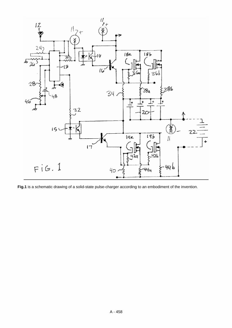
A - 458
Fig.1 is a schematic drawing of a solid-state pulse-charger according to an embodiment of the invention.

A - 459
Fig.2 is a schematic drawing of a conventional DC-to-DC converter that can be used to provide power to the pulse-charger of Fig.1 according to an embodiment of the invention.
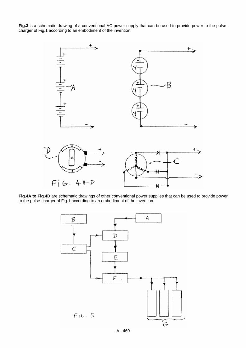
A - 460
Fig.3 is a schematic drawing of a conventional AC power supply that can be used to provide power to the pulse-charger of Fig.1 according to an embodiment of the invention.
Fig.4A to Fig.4D are schematic drawings of other conventional power supplies that can be used to provide power to the pulse-charger of Fig.1 according to an embodiment of the invention.
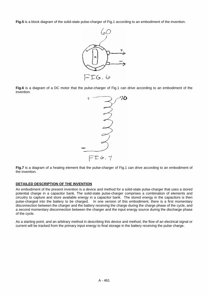
A - 461
Fig.5 is a block diagram of the solid-state pulse-charger of Fig.1 according to an embodiment of the invention.
Fig.6 is a diagram of a DC motor that the pulse-charger of Fig.1 can drive according to an embodiment of the invention.
Fig.7 is a diagram of a heating element that the pulse-charger of Fig.1 can drive according to an embodiment of the invention. DETAILED DESCRIPTION OF THE INVENTION An embodiment of the present invention is a device and method for a solid-state pulse-charger that uses a stored potential charge in a capacitor bank. The solid-state pulse-charger comprises a combination of elements and circuitry to capture and store available energy in a capacitor bank. The stored energy in the capacitors is then pulse-charged into the battery to be charged. In one version of this embodiment, there is a first momentary disconnection between the charger and the battery receiving the charge during the charge phase of the cycle, and a second momentary disconnection between the charger and the input energy source during the discharge phase of the cycle. As a starting point, and an arbitrary method in describing this device and method, the flow of an electrical signal or current will be tracked from the primary input energy to final storage in the battery receiving the pulse charge.
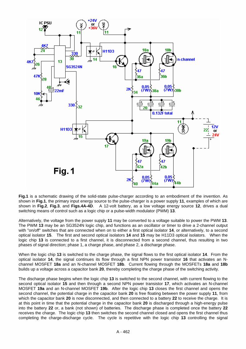
A - 462
Fig.1 is a schematic drawing of the solid-state pulse-charger according to an embodiment of the invention. As shown in Fig.1, the primary input energy source to the pulse-charger is a power supply 11, examples of which are shown in Fig.2, Fig.3, and Figs.4A-4D. A 12-volt battery, as a low voltage energy source 12, drives a dual switching means of control such as a logic chip or a pulse-width modulator (PWM) 13. Alternatively, the voltage from the power supply 11 may be converted to a voltage suitable to power the PWM 13. The PWM 13 may be an SG3524N logic chip, and functions as an oscillator or timer to drive a 2-channel output with "on/off" switches that are connected when on to either a first optical isolator 14, or alternatively, to a second optical isolator 15. The first and second optical isolators 14 and 15 may be H11D3 optical isolators. When the logic chip 13 is connected to a first channel, it is disconnected from a second channel, thus resulting in two phases of signal direction; phase 1, a charge phase, and phase 2, a discharge phase. When the logic chip 13 is switched to the charge phase, the signal flows to the first optical isolator 14. From the optical isolator 14, the signal continues its flow through a first NPN power transistor 16 that activates an N-channel MOSFET 18a and an N-channel MOSFET 18b. Current flowing through the MOSFETs 18a and 18b builds up a voltage across a capacitor bank 20, thereby completing the charge phase of the switching activity. The discharge phase begins when the logic chip 13 is switched to the second channel, with current flowing to the second optical isolator 15 and then through a second NPN power transistor 17, which activates an N-channel MOSFET 19a and an N-channel MOSFET 19b. After the logic chip 13 closes the first channel and opens the second channel, the potential charge in the capacitor bank 20 is free floating between the power supply 11, from which the capacitor bank 20 is now disconnected, and then connected to a battery 22 to receive the charge. It is at this point in time that the potential charge in the capacitor bank 20 is discharged through a high-energy pulse into the battery 22 or, a bank (not shown) of batteries. The discharge phase is completed once the battery 22 receives the charge. The logic chip 13 then switches the second channel closed and opens the first channel thus completing the charge-discharge cycle. The cycle is repetitive with the logic chip 13 controlling the signal
A - 463
direction into either channel one to the capacitor bank, or to channel two to the battery 22 from the capacitor bank. The battery 22 is given a momentary rest period without a continuous current during the charge phase. The component values for the described embodiment are as follows. The resistors 24, 26, . . . 44b have the following respective values: 4.7K, 4.7K, 47K, 330, 330, 2K, 47, 47, 0.05(7W), 0.05(7W), 2K, 47, 47, 0.05(7 W), and 0.05(7W). The potentiometer 46 is 10K, the capacitor 48 is 22 mF, and the total capacitance of the capacitor bank 20 is 0.132F. The voltage of the battery 22 is between 12-24 V, and the voltage of the power supply 11 is 24-50 V such that the supply voltage is approximately 12-15 V higher than the battery voltage. Other embodiments of the pulse-charger are contemplated. For example, the bipolar transistors 16 and 17 may be replaced with field-effect transistors, and the transistors 18a, 18b, 19a, and 19b may be replaced with bipolar or insulated-gate bipolar (IGBT) transistors. Furthermore, one can change the component values to change the cycle time, the peak pulse voltage, the amount of charge that the capacitor bank 20 delivers to the battery 22, etc. In addition, the pulse-charger can have one or more than two transistors 18a and 18b, and one or more than two transistors 19a and 19b. Still referring to Fig.1, the operation of the above-discussed embodiment of the pulse-charger is discussed. To begin the first phase of the cycle during which the capacitor bank 20 is charged, the logic circuit 13 deactivates the isolator 15 and activates the isolator 14. Typically, the circuit 13 is configured to deactivate the isolator 15 before or at the same time that it activates the isolator 14, although the circuit 13 may be configured to deactivate the isolator 15 after it activates the isolator 14. Next, the activated isolator 14 generates a base current that activates the transistor 16, which in turn generates a current that activates the transistors 18a and 18b. The activated transistors 18a and 18b charge the capacitors in the bank 20 to a charge voltage equal or approximately equal to the voltage of the power supply 11 less the lowest threshold voltage of the transistors 18a and 18b. To begin the second phase of the cycle during which the capacitor bank 20 pulse charges the battery 22, the logic circuit 13 deactivates the isolator 14 and activates the isolator 15. Typically, the circuit 13 is configured to deactivate the isolator 14 before or at the same time that it activates the isolator 15, although the circuit 13 may be configured to deactivate the isolator 14 after it activates the isolator 15. Next, the activated isolator 15 generates a base current that activates the transistor 17, which in turn generates a current that activates the transistors 19a and 19b. The activated transistors 19a and 19b discharge the capacitors in the bank 20 into the battery 22 until the voltage across the bank 20 is or is approximately equal to the voltage across the battery 22 plus the lowest threshold voltage of the transistors 19a and 19b. Alternatively, the circuit 13 can deactivate the isolator 15 at a time before the bank 20 reaches this level of discharge. Because the resistances of the transistors 19a and 19b, the resistors 44a and 44b, and the battery 22 are relatively low, the capacitors in the bank 20 discharge rather rapidly, thus delivering a pulse of current to charge the battery 22. For example, where the pulse-charger includes components having the values listed above, the bank 20 delivers a pulse of current having a duration of about 100 ms and a peak of about 250 A.

A - 464
Fig.2 is a schematic drawing of a conventional DC-to-DC converter 30 that can be used as the power supply 11 of Fig.1 according to an embodiment of the invention. A DC-to-DC converter converts a low DC voltage to a higher DC voltage or vice-versa. Therefore, such a converter can convert a low voltage into a higher voltage that the pulse-charger of Fig.1 can use to charge the capacitor bank 20 (Fig.1). More specifically, the converter 30 receives energy from a source 31 such as a 12-volt battery. An optical isolator sensor 33 controls an NPN power transistor which provides a current to a primary coil 36 of a power transformer 32. A logic chip or pulse width modulator (PWM) 34 alternately switches on and off an IRF260 first N-channel MOSFET 35a and an IRF260 second N-channel MOFSET 35b such that when the MOSFET 35a is on the MOSFET 35b is off and vice-versa. Consequently, the switching MOSFETs 35a and 35b drive respective sections of the primary coil 36 to generate an output voltage across a secondary coil 38. A full-wave bridge rectifier 39 rectifies the voltage across the secondary coil 38, and this rectified voltage is provided to the pulse-charger of Fig.1. Furthermore, the secondary coil 38 can be tapped to provide a lower voltage for the PWM 13 of Fig.1 such that the DC-to-DC converter 30 can be used as both the power supply 11 and the low-voltage supply 12 of Fig.1.

A - 465
Fig.3 is a schematic drawing of an AC power supply 40 that can be used as both the power supply 11 and the power supply 12 of Fig.1 according to an embodiment of the invention. The power input 42 to the supply 40 is 120V AC. A first transformer 44 and full-wave rectifier 46 compose the supply 11, and a second transformer 48, full-wave rectifier 50, and voltage regulator 52 compose the supply 12. Fig.4A to Fig.4D are schematic drawings of various conventional primary energy input sources which can be used as the supply 11 and/or the supply 12 of Fig.1 according to an embodiment of the invention. Fig.4A is a schematic drawing of serially coupled batteries. Fig.4B is a schematic drawing of serially-coupled solar cells. Fig.4C is a schematic drawing of an AC generator, and Fig.4D is a schematic drawing of a DC generator.
Fig.5 is a block diagram of the solid-state pulse-charger of Fig.1 according to an embodiment of the invention. Block A is the power supply 11, which can be any suitable power supply such as those shown in Fig.2, Fig.3, Figs.4A-4D. Block B is the power supply 12, which can be any suitable power supply such as a 12V DC supply or the supply shown in Fig.3. Block C is the PWM 13 and its peripheral components. Block D is the charge switch that includes the first optical isolator chip 14, the first NPN power transistor 16, the first set of two N-

A - 466
channel MOSFETs 18a and 18b, and their peripheral resistors. Block E is the capacitor bank 20. Block F is the discharge switch that includes the second optical isolator chip 15, the second NPN power transistor 17, the second set of two N-channel MOSFETs 19a and 19b, and their peripheral resistors. Block G is the battery or battery bank 22 which is being pulse-charged. A unique feature that distinguishes one embodiment of the pulse-charger described above, from conventional chargers is the method charging the battery with pulses of current instead of with a continuous current. Consequently, the battery is given a reset period between pulses. Fig.6 is a diagram of a DC motor 60 that the pulse-charger of Fig.1 can drive according to an embodiment of the invention. Specifically, one can connect the motor 60 in place of the battery 22 (Fig.1) such that the pulse-charger drives the motor with pulses of current. Although one need not modify the pulse-charger to drive the motor 60, one can modify it to make it more efficient for driving the motor. For example, one can modify the values of the resistors peripheral to the PWM 13 (Fig.1) to vary the width and peak of the drive pulses from the capacitor bank 20 (Fig.1). Fig.7 is a diagram of a heating element 70, such as a dryer or water-heating element, that the pulse-charger of Fig.1 can drive according to an embodiment of the invention. Specifically, one can connect the heating element 70 in place of the battery 22 (Fig.1) such that the pulse-charger drives the element with pulses of current. Although one need not modify the pulse-charger to drive the element 70, one can modify it to make it more efficient for driving the element. For example, one can modify the values of the resistors peripheral to the PWM 13 (Fig.1) to vary the width and peak of the drive pulses from the capacitor bank 20 (Fig.1). In the embodiments discussed above, specific electronic elements and components are used. However, it is known that a variety of available transistors, resistors, capacitors, transformers, timing components, optical isolators, pulse width modulators, MOSFETs, and other electronic components may be used in a variety of combinations to achieve an equivalent result. Finally, although the invention has been described with reference of particular means, materials and embodiments, it is to be understood that the invention is not limited to the particulars disclosed and extends to all equivalents within the scope of the claims. CLAIMS 1. A solid-state pulse battery charger wherein input power from a primary source is stored as a potential charge in
a capacitor bank, said capacitor bank then disconnected from said input power source through a dual timing means, said capacitor then connected to a battery to receive the potential charge, the charge then discharged into said battery from said capacitor, said battery then disconnected from said capacitor through said dual timing means, said capacitor then re-connected to said input power source completing a two phase switching cycle comprising:
a. a means for providing input power; b. a means for timing a signal and a current flow in two phases, a charge phase and a discharge phase,
through either a first channel output for charging said capacitor bank, or a second channel output for discharging stored energy from said capacitor into said battery, the current flowing from said first channel output through a first optical isolator and through a first NPN power transistor, said first transistor activating a first pair of N-channel MOSFETs with voltage stored as the potential charge in said capacitor bank, said capacitor disconnecting from said input power means by said timing means;
c. said means for timing current flow connecting to said second channel output, current flowing from said second channel through a second optical isolator and through a second NPN power transistor, said second transistor activating a second pair of N-channel MOSFETs, said capacitor connecting to said battery, the potential charge discharging into said battery, said timing means disconnecting said capacitor from said battery, and connecting said capacitor to said power means.
2. The pulse-charger of claim 1 wherein the means for providing input power is an AC voltage current. 3. The pulse-charger of claim 1 wherein the means for providing input power is a battery. 4. The pulse-charger of claim 1 wherein the means for providing input power is a DC generator. 5. The pulse-charger of claim 1 wherein the means for providing input power is an AC generator. 6. The pulse-charger of claim 1 wherein the means for providing input power is a solar cell. 7. The pulse-charger of claim 1 wherein the means for providing input power is a DC-to-DC inverter.
A - 467
8. The pulse-charger of claim 1 wherein the means for timing a signal is a pulse width modulator, said modulator an SG3524N logic chip. 9. The pulse-charger of claim 1 wherein the optical isolator is an H11D3 isolator. 10. The pulse-charger of claim 1 wherein the NPN power transistor is an MJE15024 transistor. 11. The pulse-charger of claim 1 wherein the N-channel MOSFET is a IRF260 MOSFET. 12. A solid-state pulsed battery charger wherein input power from a primary source is stored as a potential charge
in a capacitor bank, said capacitor then disconnected from said input power source through a dual timing means, said capacitor then connected to a battery to receive the potential charge, the charge then discharged into said battery from said capacitor, said battery then disconnected from said capacitor through said dual timing means, said capacitor then reconnected to said input power source completing a two phase cycle comprising:
a. a means for providing said input power, said means either an AC voltage current, or a battery, or a DC generator, or an AC generator, or a solar cell, or a DC-to-DC inverter;
b. a means for timing a signal and a current flow, said timing means a pulse width modulator, logic chip SG3524N, the current flowing through either a first channel output, or a second channel output, the current flowing from said first channel output through a first optical isolator, said isolator an H11D3, and through a first NPN power transistor, said transistor an MJE15024, said first transistor activating a first pair of N-channel MOSFETs, said MOSFETs an IRF260, with current voltage stored as the potential charge in said capacitor bank, said capacitor disconnecting from said input power means by said logic chip;
c. said timing logic chip connecting to said second channel output, current flowing from said second channel through a second optical isolator, said isolator an H11D3, and through a second NPN power transistor, said second transistor an MJE15024, and activating a second pair of N-channel MOSFETs, said MOSFETs an IRF260, with current voltage stored as the potential charge in said capacitor bank, said capacitor disconnecting from said input power means by said logic chip, said capacitor connecting to said battery, the potential charge discharging into said battery, said timing means disconnecting said capacitor from said battery and connecting said capacitor to said power means.
13. A method of making a solid-state pulse battery charger wherein input power from a primary source is stored
as a potential charge in a capacitor bank, said capacitor disconnected from said input power source through a dual timing means, said capacitor connected to a battery to receive the potential charge, said charge discharged into said battery from said capacitor, said battery disconnected from said capacitor through said dual timing means, said capacitor reconnected to said input power source completing a two phase cycle comprising the steps of:
a. providing a source of input power; b. connecting a means for dual-timing said charger to control a signal or current flow through a first channel
output comprising a first optical isolator, a first NPN power transistor and a first pair of N-channel MOSFETs;
c. capturing energy from said current and storing said energy in said capacitor bank thereby charging said capacitor;
d. switching the flow of said current using said timing device to a second channel comprising a second optical isolator, a second NPN power transistor and a second pair of N-channel MOSFETs, thus disconnecting said capacitor from said power source and connecting said capacitor to said battery;
e. discharging the potential charge into said battery; f. switching the flow of the current using said timing device to said power source and said first channel to
complete said cycle. 14. The pulse-charger of claim 13 wherein the means for providing input power is an AC voltage current. 15. The pulse-charger of claim 13 wherein the means for providing input power is a battery. 16. The pulse-charger of claim 13 wherein the means for providing input power is a DC generator. 17. The pulse-charger of claim 13 wherein the means for providing input power is an AC generator. 18. The pulse-charger of claim 13 wherein the means for providing input power is a solar cell. 19. The pulse-charger of claim 13 wherein the means for providing input power is a DC-to-DC inverter. 20. The pulse-charger of claim 13 wherein the means for timing a signal is a pulse width modulator, said
modulator an SG3524N logic chip.
A - 468
21. The pulse-charger of claim 13 wherein the optical isolator is an H11D3 isolator. 22. The pulse-charger of claim 13 wherein the NPN power transistor is an MJE15024 transistor. 23. The pulse-charger of claim 13 wherein the N-channel MOSFET is a IRF260 MOSFET. 24. A battery charger, comprising:
a supply node; a charge node; a switch circuit coupled to the supply and the charge nodes and operable to, allow a battery-charge current to
flow into the charge node during a battery-charge period, and prohibit the battery-charge current from flowing into the charge node during a battery-rest period.
25. The battery charger of claim 24, further comprising:
a charge-storage device coupled to the switch circuit; and wherein the switch circuit is operable to, allow the battery-charge current to flow from the charge-storage
device into the charge node during the battery-charge period, and charge the charge-storage device during the battery-rest period.
26. The battery charger of claim 24, further comprising:
a capacitor coupled to the switch circuit; and wherein the switch circuit is operable to, allow the battery-charge current to from the capacitor into the charge
node during the battery-charge period, and charge the capacitor during the battery-rest period.
27. A method, comprising:
charging a battery during a first period of a charge cycle; and prohibiting the charging of the battery during a second period of the charge cycle.
28. The method of claim 27 wherein:
charging the battery comprises charging the battery with a charge current during the first period of the charge cycle; and
prohibiting the charging of the battery comprises prohibiting the charge current from flowing into the battery during the second period of the charge cycle.
29. The method of claim 27 wherein:
charging the battery comprises discharging a capacitor into the battery during the first period of the charge cycle; and
prohibiting the charging of the battery comprises uncoupling the capacitor from the battery during the second period of the charge cycle.
30. The method of claim 27, further comprising:
wherein charging the battery comprises discharging a capacitor into the battery during the first period of the charge cycle;
wherein prohibiting the charging of the battery comprises uncoupling the capacitor from the battery during the second period of the charge cycle; and
charging the capacitor during the second period of the charge cycle. 31. A method, comprising:
discharging a charge-storage device into a battery during a first period of a battery-charge cycle; and uncoupling the charge-storage device from the battery and charging the charge-storage device during a
second period of the battery-charge cycle. 32. The method of claim 31 wherein uncoupling the charge-storage device comprises uncoupling the charge-
storage device from the battery before commencing charging of the charge-storage device. 33. The method of claim 31 wherein uncoupling the charge-storage device comprises uncoupling the charge-
storage device from the battery after commencing charging of the charge-storage device. 34. The method of claim 31 wherein uncoupling the charge-storage device comprises simultaneously uncoupling
the charge-storage device from the battery and commencing charging of the charge-storage device.
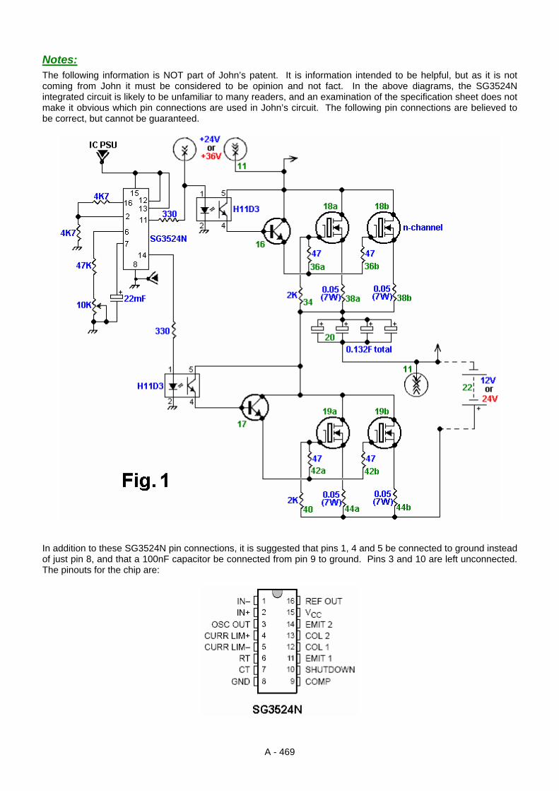
A - 469
Notes: The following information is NOT part of John’s patent. It is information intended to be helpful, but as it is not coming from John it must be considered to be opinion and not fact. In the above diagrams, the SG3524N integrated circuit is likely to be unfamiliar to many readers, and an examination of the specification sheet does not make it obvious which pin connections are used in John’s circuit. The following pin connections are believed to be correct, but cannot be guaranteed.
In addition to these SG3524N pin connections, it is suggested that pins 1, 4 and 5 be connected to ground instead of just pin 8, and that a 100nF capacitor be connected from pin 9 to ground. Pins 3 and 10 are left unconnected. The pinouts for the chip are: