
APPENDIX 1 INTERCONNECTION REQUEST PROJECT … 1 INTERCONNECTION REQUEST The undersigned...
32
APPENDIX 1 INTERCONNECTION REQUEST The undersigned Interconnection Customer submits this request to interconnect its Large Generating Facility to the Administered Transmission System under Schedule 22 - Large Generator Interconnection Procedures (“LGIP”) of the ISO New England Inc. Open Access Transmission Tariff (the “Tariff”). Capitalized terms have the meanings specified in the Tariff. PROJECT INFORMATION Proposed Project Name:________________________________________________________________ 1. This Interconnection Request is for (check one): __________ A proposed new Large Generating Facility __________ An increase in the generating capacity or a modification that has the potential to be a Material Modification of an existing Generating Facility __________ Commencement of participation in the wholesale markets by an existing Generating Facility __________ A change from Network Resource Interconnection Service to Capacity Network Resource Interconnection Service 2. The types of Interconnection Service requested: __________ Network Resource Interconnection Service (energy capability only) __________ Capacity Network Resource Interconnection Service (energy capability and capacity capability) If Capacity Network Resource Interconnection Service, does Interconnection Customer request Long Lead Facility treatment? Check: ____Yes or ___ No
Transcript of APPENDIX 1 INTERCONNECTION REQUEST PROJECT … 1 INTERCONNECTION REQUEST The undersigned...
APPENDIX 1
INTERCONNECTION REQUEST
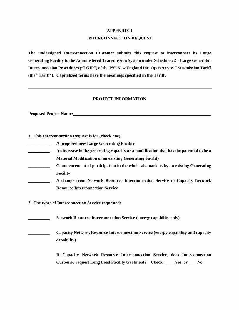
The undersigned Interconnection Customer submits this request to interconnect its Large
Generating Facility to the Administered Transmission System under Schedule 22 - Large Generator
Interconnection Procedures (“LGIP”) of the ISO New England Inc. Open Access Transmission Tariff
(the “Tariff”). Capitalized terms have the meanings specified in the Tariff.
PROJECT INFORMATION
Proposed Project Name:________________________________________________________________
1. This Interconnection Request is for (check one):
__________ A proposed new Large Generating Facility
__________ An increase in the generating capacity or a modification that has the potential to be a
Material Modification of an existing Generating Facility
__________ Commencement of participation in the wholesale markets by an existing Generating
Facility
__________ A change from Network Resource Interconnection Service to Capacity Network
Resource Interconnection Service
2. The types of Interconnection Service requested:
__________ Network Resource Interconnection Service (energy capability only)
__________ Capacity Network Resource Interconnection Service (energy capability and capacity
capability)
If Capacity Network Resource Interconnection Service, does Interconnection
Customer request Long Lead Facility treatment? Check: ____Yes or ___ No
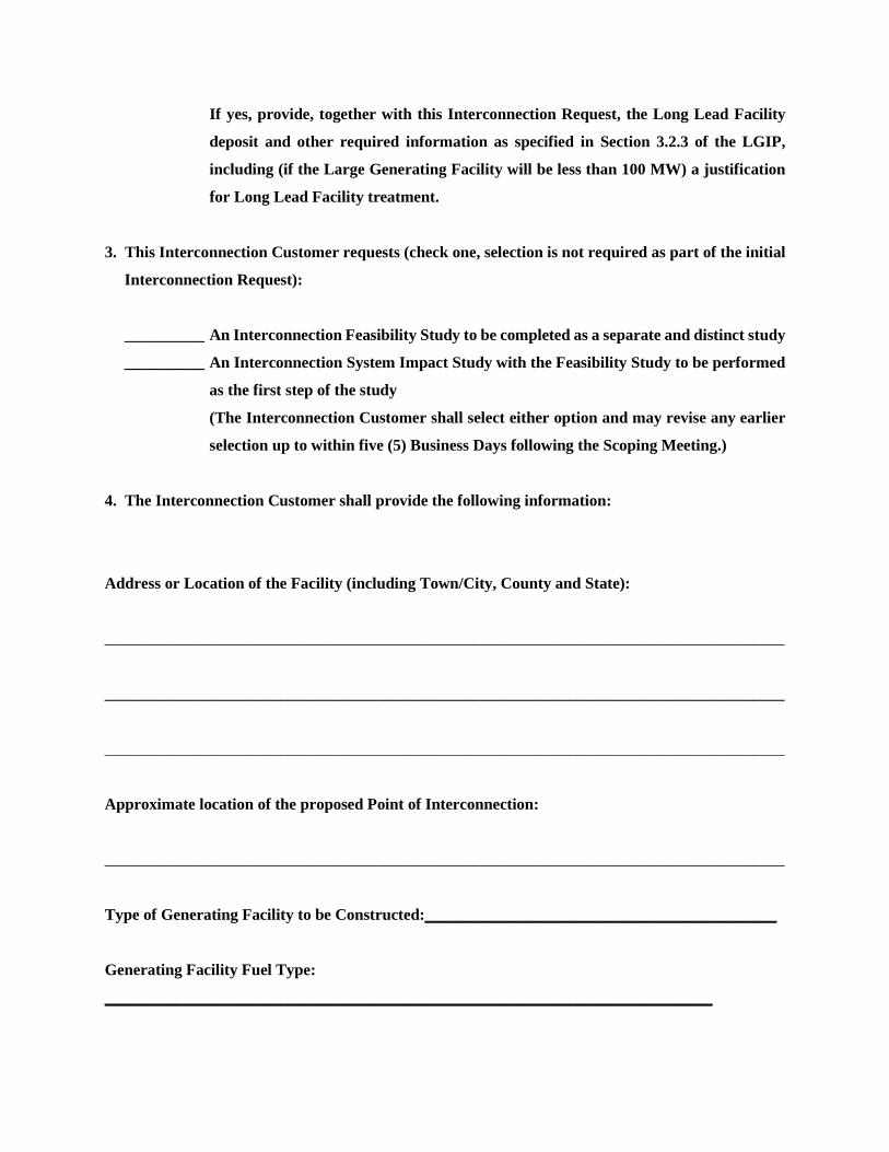
If yes, provide, together with this Interconnection Request, the Long Lead Facility
deposit and other required information as specified in Section 3.2.3 of the LGIP,
including (if the Large Generating Facility will be less than 100 MW) a justification
for Long Lead Facility treatment.
3. This Interconnection Customer requests (check one, selection is not required as part of the initial
Interconnection Request):
__________ An Interconnection Feasibility Study to be completed as a separate and distinct study
__________ An Interconnection System Impact Study with the Feasibility Study to be performed
as the first step of the study
(The Interconnection Customer shall select either option and may revise any earlier
selection up to within five (5) Business Days following the Scoping Meeting.)
4. The Interconnection Customer shall provide the following information:
Address or Location of the Facility (including Town/City, County and State):
_____________________________________________________________________________________
_____________________________________________________________________________________
_____________________________________________________________________________________
Approximate location of the proposed Point of Interconnection:
_____________________________________________________________________________________
Type of Generating Facility to be Constructed:____________________________________________
Generating Facility Fuel Type:
____________________________________________________________________________
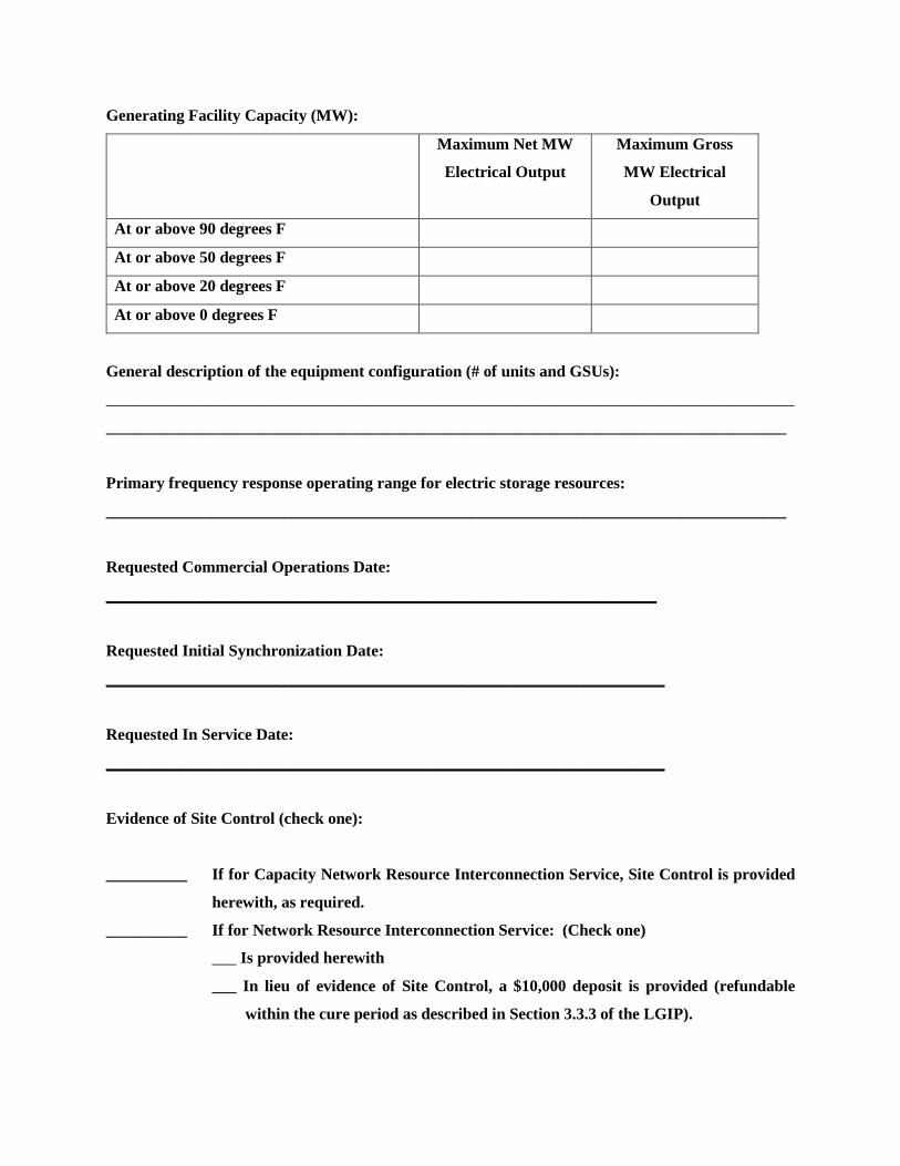
Generating Facility Capacity (MW):
Maximum Net MW
Electrical Output
Maximum Gross
MW Electrical
Output
At or above 90 degrees F
At or above 50 degrees F
At or above 20 degrees F
At or above 0 degrees F
General description of the equipment configuration (# of units and GSUs):
_____________________________________________________________________________________
____________________________________________________________________________________
Primary frequency response operating range for electric storage resources:
____________________________________________________________________________________
Requested Commercial Operations Date:
____________________________________________________________________
Requested Initial Synchronization Date:
_____________________________________________________________________
Requested In Service Date:
_____________________________________________________________________
Evidence of Site Control (check one):
__________ If for Capacity Network Resource Interconnection Service, Site Control is provided
herewith, as required.
__________ If for Network Resource Interconnection Service: (Check one)
___ Is provided herewith
___ In lieu of evidence of Site Control, a $10,000 deposit is provided (refundable
within the cure period as described in Section 3.3.3 of the LGIP).

__________ Site Control is not provided because the proposed modification is to the
Interconnection Customer’s existing Large Generating Facility and, by checking
this option, the Interconnection Customer certifies that it has Site Control and that
the proposed modification does not require additional real property.
The technical data specified within the applicable attachment to this form (check one):
__________ Is included with the submittal of this Interconnection Request form
__________ Will be provided on or before the execution and return of the Feasibility Study
Agreement (Attachment B) or the System Impact Study Agreement (Attachment A),
as applicable
The ISO will post the Project Information on the ISO web site under “New Interconnections” and
OASIS.
CUSTOMER INFORMATION
Company Name:_____________________________________________________________________
ISO Customer ID# (If available):_______________________________________________________
(Interconnection Customer)
Company Address: PO Box No.:
____________________________________________________________
Street Address:____________________________________________________
City, State ZIP:
Company Representative: Name: ____________________________________________________
Title: ___________________________________________________
Company Representative’s Company and Address (if different from above):

Company Name:
PO Box No.:
Street Address:
City, State ZIP:
Phone: __________________ FAX: ___________________ email:___________________________
This Interconnection Request is submitted by:
Authorized Signature:_________________________________________________________________
Name (type or print):_________________________________________________________________
Title:______________________________________________________________________________
Date:_______________________________________________________________________________
In order for an Interconnection Request to be considered a valid request, it must:
(a) Be accompanied by a deposit of $50,000.00 that is provided electronically and which may be
refundable in accordance with Section 3.3.1 of the LGIP;
(b) For Capacity Network Resource Interconnection Service, include documentation demonstrating
Site Control. If for Network Resource Interconnection Service, demonstrate Site Control or post an
additional deposit of $10,000.00. If the Interconnection Customer with an Interconnection Request
for Network Resource Interconnection Service demonstrates Site Control within the cure period
specified in Section 3.3.1 of the LGIP, the additional deposit of $10,000.00 shall be refundable (An
Interconnection Customer does not need to demonstrate Site Control for an Interconnection Request
for a modification to its existing Large Generating Facility where the Interconnection Customer has

certified that it has Site Control and that the proposed modification does not require additional real
property);
(c) Include a detailed map, such as a map of the quality produced by the U.S. Geological Survey, which
clearly indicates the site of the new facility and pertinent surrounding structures; and
(d) Include all information required on the Interconnection Request form and attachments thereto; and
(e) Include the deposit and all information required for Long Lead Facility treatment, if such treatment
is requested in accordance with Section 3.2.3 of the LGIP.
The Interconnection Request must be submitted to the System Operator via the Interconnection Request
Tracking Tool or IRTT, a web-based application for submitting, tracking and viewing Interconnection
Requests available on the ISO New England website.
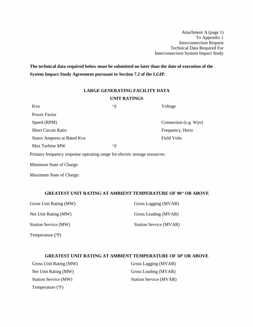
Attachment A (page 1) To Appendix 1
Interconnection Request Technical Data Required For
Interconnection System Impact Study
The technical data required below must be submitted no later than the date of execution of the
System Impact Study Agreement pursuant to Section 7.2 of the LGIP.
LARGE GENERATING FACILITY DATA
UNIT RATINGS
Kva °F Voltage
Power Factor
Speed (RPM) Connection (e.g. Wye)
Short Circuit Ratio Frequency, Hertz
Stator Amperes at Rated Kva Field Volts
Max Turbine MW °F
Primary frequency response operating range for electric storage resources: Minimum State of Charge:
Maximum State of Charge:
GREATEST UNIT RATING AT AMBIENT TEMPERATURE OF 90 o OR ABOVE
Gross Unit Rating (MW) Gross Lagging (MVAR)
Net Unit Rating (MW) Gross Leading (MVAR)
Station Service (MW) Station Service (MVAR)
Temperature (oF)
GREATEST UNIT RATING AT AMBIENT TEMPERATURE OF 50o OR ABOVE
Gross Unit Rating (MW) Gross Lagging (MVAR)
Net Unit Rating (MW) Gross Leading (MVAR)
Station Service (MW) Station Service (MVAR)
Temperature (oF)
Attachment A (page 2) To Appendix 1
Interconnection Request Technical Data Required For
Interconnection System Impact Study
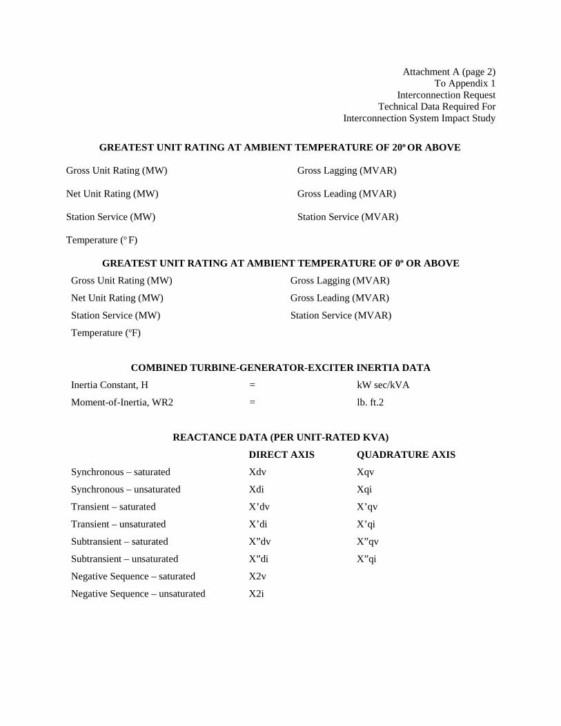
GREATEST UNIT RATING AT AMBIENT TEMPERATURE OF 20o OR ABOVE
Gross Unit Rating (MW) Gross Lagging (MVAR)
Net Unit Rating (MW) Gross Leading (MVAR)
Station Service (MW) Station Service (MVAR)
Temperature (o F)
GREATEST UNIT RATING AT AMBIENT TEMPERATURE OF 0o OR ABOVE
Gross Unit Rating (MW) Gross Lagging (MVAR)
Net Unit Rating (MW) Gross Leading (MVAR)
Station Service (MW) Station Service (MVAR)
Temperature (oF)
COMBINED TURBINE-GENERATOR-EXCITER INERTIA DATA
Inertia Constant, H = kW sec/kVA
Moment-of-Inertia, WR2 = lb. ft.2
REACTANCE DATA (PER UNIT-RATED KVA)
DIRECT AXIS QUADRATURE AXIS
Synchronous – saturated Xdv Xqv
Synchronous – unsaturated Xdi Xqi
Transient – saturated X’dv X’qv
Transient – unsaturated X’di X’qi
Subtransient – saturated X”dv X”qv
Subtransient – unsaturated X”di X”qi
Negative Sequence – saturated X2v
Negative Sequence – unsaturated X2i

Attachment A (page 3) To Appendix 1
Interconnection Request Technical Data Required For
Interconnection System Impact Study FIELD TIME CONSTANT DATA (SEC)
Zero Sequence – saturated X0v
Zero Sequence – unsaturated X0i
Leakage Reactance Xlm
Open Circuit T’qo T’do
Three-Phase Short Circuit Transient T’d3 T’q
Line to Line Short Circuit Transient T’d2
Line to Neutral Short Circuit Transient T’d1
Short Circuit Subtransient T”d T”q
Open Circuit Subtransient T”do T”qo
ARMATURE TIME CONSTANT DATA (SEC)
Three Phase Short Circuit Ta3
Line to Line Short Circuit Ta2
Line to Neutral Short Circuit Ta1
NOTE: If requested information is not applicable, indicate by marking “N/A.”
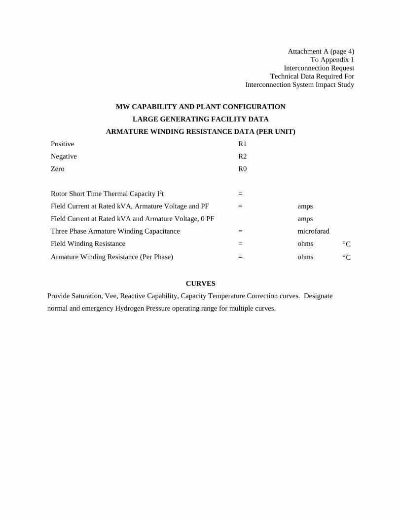
Attachment A (page 4) To Appendix 1
Interconnection Request Technical Data Required For
Interconnection System Impact Study
MW CAPABILITY AND PLANT CONFIGURATION
LARGE GENERATING FACILITY DATA
ARMATURE WINDING RESISTANCE DATA (PER UNIT)
Positive R1
Negative R2
Zero R0
Rotor Short Time Thermal Capacity I2t =
Field Current at Rated kVA, Armature Voltage and PF = amps
Field Current at Rated kVA and Armature Voltage, 0 PF amps
Three Phase Armature Winding Capacitance = microfarad
Field Winding Resistance = ohms °C
Armature Winding Resistance (Per Phase) = ohms °C
CURVES
Provide Saturation, Vee, Reactive Capability, Capacity Temperature Correction curves. Designate
normal and emergency Hydrogen Pressure operating range for multiple curves.
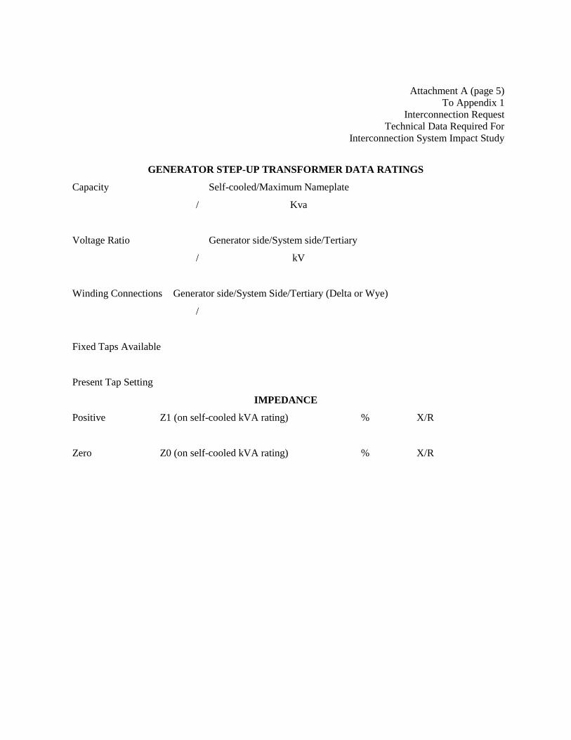
Attachment A (page 5) To Appendix 1
Interconnection Request Technical Data Required For
Interconnection System Impact Study
GENERATOR STEP-UP TRANSFORMER DATA RATINGS
Capacity Self-cooled/Maximum Nameplate
/ Kva
Voltage Ratio Generator side/System side/Tertiary
/ kV
Winding Connections Generator side/System Side/Tertiary (Delta or Wye)
/
Fixed Taps Available
Present Tap Setting
IMPEDANCE
Positive Z1 (on self-cooled kVA rating) % X/R
Zero Z0 (on self-cooled kVA rating) % X/R

Attachment A (page 6) To Appendix 1
Interconnection Request Technical Data Required For
Interconnection System Impact Study
EXCITATION SYSTEM DATA
Identify appropriate IEEE model block diagram of excitation system and power system stabilizer
(“PSS”) for computer representation in power system stability simulations and the corresponding
excitation system and PSS constants for use in the model.
GOVERNOR SYSTEM DATA
Identify appropriate IEEE model block diagram of governor system for computer representation in power
system stability simulations and the corresponding governor system constants for use in the model.
WIND AND INVERTER-BASED GENERATORS
A completed Attachment A-1 Supplementary Wind and Inverter-Based Generating Facility Form to this
Attachment A, must be supplied for all Interconnection Requests for wind and inverter-based Generating
Facilities.
MODEL REQUIREMENTS
For all Generating Facility types: A completed, fully functioning, public (i.e., non-proprietary, non-
confidential) Siemens PTI’s (“PSSE”) power flow model or other compatible formats, such as IEEE and
General Electric Company Power Systems Load Flow (“PSLF”) data sheet , must be supplied with this
Attachment A. If additional public data sheets are more appropriate to the proposed device then they
shall be provided and discussed at the Scoping Meeting. For all Interconnection Studies commencing
after January 1, 2017, all power flow models must be standard library models in PSS/E or applicable
applications. After January 1, 2017, user-models will not be accepted.

Attachment A (page 7) To Appendix 1
Interconnection Request Technical Data Required For
Interconnection System Impact Study
A PSCAD model for all wind and inverter-based Generating Facilities must be supplied with this
Attachment A. If a PSCAD model is deemed required for other Generating Facility types at the Scoping
Meeting, such PSCAD model must be provided to the System Operator within ninety (90) Calendar Days
of the executed Interconnection System Impact Study Agreement. A benchmarking analysis, consistent
with the requirements in the ISO New England Planning Procedures, confirming acceptable performance
of the PSS/E model in comparison to the PSCAD model, shall be provided at the time PSCAD model is
submitted.

Attachment A (page 8) To Appendix 1
Interconnection Request Technical Data Required For
Interconnection System Impact Study INDUCTION GENERATORS:
(*) Field Volts:
(*) Field Amperes:
(*) Motoring Power (kW):
(*) Neutral Grounding Resistor (If Applicable):
(*) I22t or K (Heating Time Constant):
(*) Rotor Resistance:
(*) Stator Resistance:
(*) Stator Reactance:
(*) Rotor Reactance:
(*) Magnetizing Reactance:
(*) Short Circuit Reactance:
(*) Exciting Current:
(*) Temperature Rise:
(*) Frame Size:
(*) Design Letter:
(*) Reactive Power Required In Vars (No Load):
(*) Reactive Power Required In Vars (Full Load):
(*) Total Rotating Inertia, H: Per Unit on KVA Base
Note: Please consult System Operator prior to submitting the Interconnection Request to
determine if the information designated by (*) is required.
Applicant Signature
I hereby certify that, to the best of my knowledge, all the information provided in this Attachment A to
the Interconnection Request is true and accurate.
For Interconnection Customer:_____________________________Date:_________________________

Attachment A-1 (page 1) To Attachment A of Appendix 1
Supplementary Wind and Inverter-Based
Generating Facility Form
SUPPLEMENTARY WIND AND INVERTER-BASED GENERATING FACILITY DATA FORM
1. Attach a Geographic Map Demonstrating the Project Layout and its Interconnection to the Power Grid. (Specify the name of the attachment here)
2. Attach a Bus-Breaker Based One-line Diagram (The diagram should include each of the individual unit generators, generator number, rating and terminal voltage.) ( Specify the name of the attachment here)
2.1 Collection system detail impedance sheet
If a collector system is used, attach a collector system data sheet in accordance with the one-line
diagram attached above. The data sheet should include: the type, length Z0, Z1 and Xc/B of each
circuit (feeder and collector string).
Specify the name of the attachment here: _______________
2.2 Collection system aggregate (equivalent) model data sheet
Attach an aggregate (equivalent) collection system data sheet. The data table should include:
the type, length, Z0, Z1 and Xc/B of the equivalent circuits (feeders and collector strings).
Specify the name of the attachment here: _______________

Attachment A-1 (page 2) To Attachment A of Appendix 1
Supplementary Wind and Inverter-Based
Generating Facility Form
3. Summary of the Unit Models in the wind or inverter-based generating facility (List all different unit models in the facility)
Manufacturer Model
Type of this WTG* (if applicable)
Generator Unit Numbers in the field
Number(s) of these Units
Maximum Output of this Unit (MW)
Total MW
* Type 1 – Cage rotor induction generators Type 2 – Induction generators with variable rotor resistance Type 3 – Doubly-fed asynchronous generators with rotor-side converter Type 4 – Full-power converter interface Repeat the following sections from 4 to 12 for each different unit model.

Attachment A-1 (page 3) To Attachment A of Appendix 1
Supplementary Wind and Inverter-Based
Generating Facility Form
4. Unit Detail Information
Unit Manufacturer Model
Terminal Voltage
Rating of Each Unit (MVA)
Maximum Gross Electrical Output (MW)
Minimum Gross Electrical Output(MW)
Lagging Reactive Power Limit at Rated Real Power Output
(MVAR)
Leading Reactive Power Limit at Rated Real Power Output
(MVAR)
Lagging Reactive Power Limit at Zero Real Power Output
(MVAR)
Leading Reactive Power Limit at Zero Real Power Output
(MVAR)
Station Service Load(MW, MVAR)
Minimum short circuit ratio(SCR) requirement by
manufacturer
On which bus the minimum SCR is required by
manufacturer
What voltage level the minimum SCR is required by
manufacturer
Positive sequence Xsource
Zero sequence Xsource
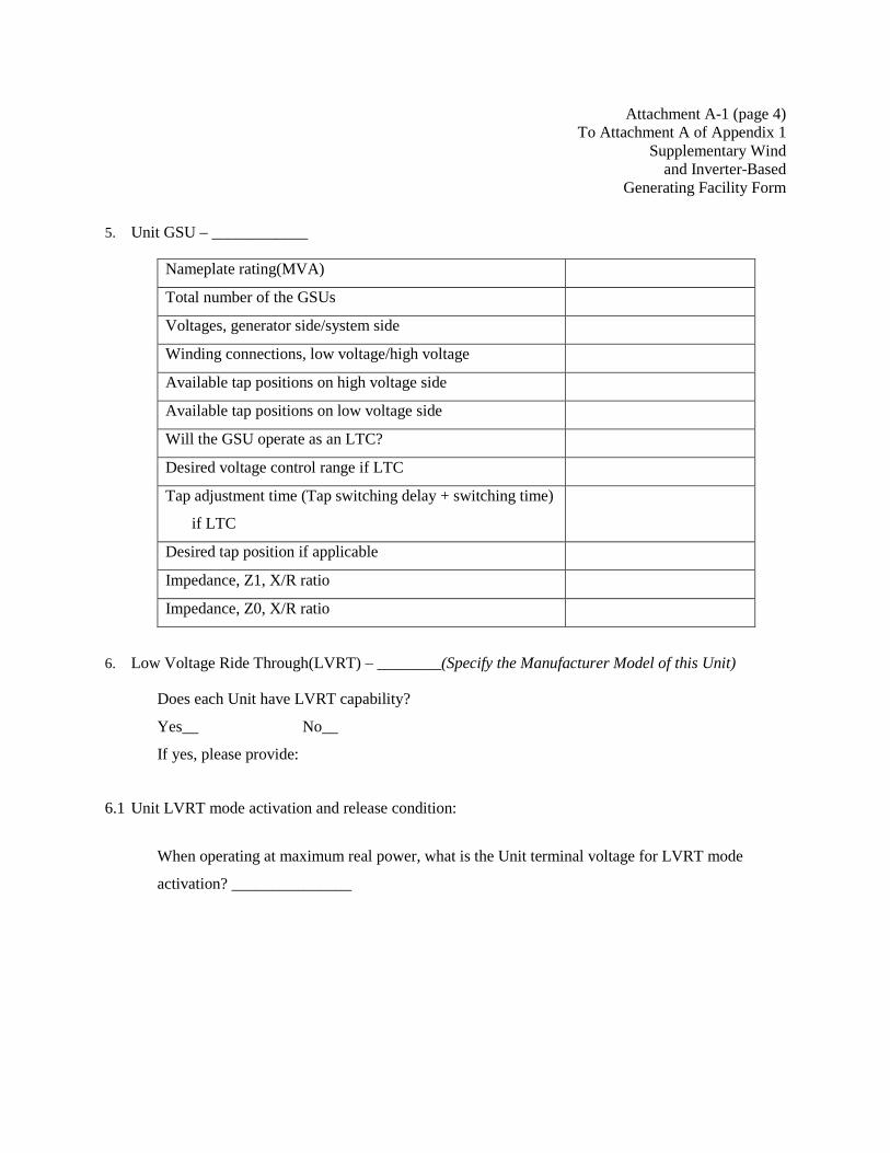
Attachment A-1 (page 4) To Attachment A of Appendix 1
Supplementary Wind and Inverter-Based
Generating Facility Form
5. Unit GSU – ____________
Nameplate rating(MVA)
Total number of the GSUs
Voltages, generator side/system side
Winding connections, low voltage/high voltage
Available tap positions on high voltage side
Available tap positions on low voltage side
Will the GSU operate as an LTC?
Desired voltage control range if LTC
Tap adjustment time (Tap switching delay + switching time)
if LTC
Desired tap position if applicable
Impedance, Z1, X/R ratio
Impedance, Z0, X/R ratio
6. Low Voltage Ride Through(LVRT) – ________(Specify the Manufacturer Model of this Unit)
Does each Unit have LVRT capability?
Yes__ No__
If yes, please provide:
6.1 Unit LVRT mode activation and release condition:
When operating at maximum real power, what is the Unit terminal voltage for LVRT mode
activation? _______________

Attachment A-1 (page 5) To Attachment A of Appendix 1
Supplementary Wind and Inverter-Based
Generating Facility Form
When operating at maximum real power, what is the Unit terminal voltage for releasing LVRT
mode after it is activated? _________
If there is different LVRT activation and release logic, please state here _________________
6.2 A wind or other inverter-based generating facility technical manual from the manufacturer
including description of LVRT functionality:
Attach the file and specify the name of the attachment here:
______________________________
6.3 Does the wind or other inverter-based generating facility technical manual attached above include
a reactive power capability curve?
Yes__ No__
If no, attach the file and specify the name of the attachment here:
______________________________
7. Low Voltage Protection (considering LVRT functionality)
(Specify the Manufacturer Model of this Unit)
Low Voltage Setting (pu) Relay Pickup Time (Seconds)
*Add more rows in the table as needed
8. High Voltage Protection - ________(Specify the Manufacturer Model of this Unit)
Attachment A-1 (page 6) To Attachment A of Appendix 1
Supplementary Wind and Inverter-Based
Generating Facility Form
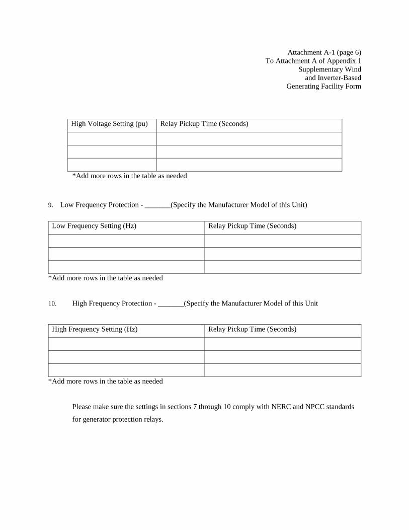
High Voltage Setting (pu) Relay Pickup Time (Seconds)
*Add more rows in the table as needed
9. Low Frequency Protection - _______(Specify the Manufacturer Model of this Unit)
Low Frequency Setting (Hz) Relay Pickup Time (Seconds)
*Add more rows in the table as needed
10. High Frequency Protection - _______(Specify the Manufacturer Model of this Unit
High Frequency Setting (Hz) Relay Pickup Time (Seconds)
*Add more rows in the table as needed
Please make sure the settings in sections 7 through 10 comply with NERC and NPCC standards
for generator protection relays.
Attachment A-1 (page 7) To Attachment A of Appendix 1
Supplementary Wind and Inverter-Based
Generating Facility Form
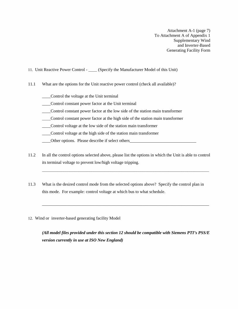
11. Unit Reactive Power Control - ____ (Specify the Manufacturer Model of this Unit)
11.1 What are the options for the Unit reactive power control (check all available)?
____Control the voltage at the Unit terminal
____Control constant power factor at the Unit terminal
____Control constant power factor at the low side of the station main transformer
____Control constant power factor at the high side of the station main transformer
____Control voltage at the low side of the station main transformer
____Control voltage at the high side of the station main transformer
____Other options. Please describe if select others
11.2 In all the control options selected above, please list the options in which the Unit is able to control
its terminal voltage to prevent low/high voltage tripping.
______________________________________________________________________________
11.3 What is the desired control mode from the selected options above? Specify the control plan in
this mode. For example: control voltage at which bus to what schedule.
______________________________________________________________________________
12. Wind or inverter-based generating facility Model
(All model files provided under this section 12 should be compatible with Siemens PTI’s PSS/E
version currently in use at ISO New England)
Attachment A-1 (page 8) To Attachment A of Appendix 1
Supplementary Wind and Inverter-Based
Generating Facility Form
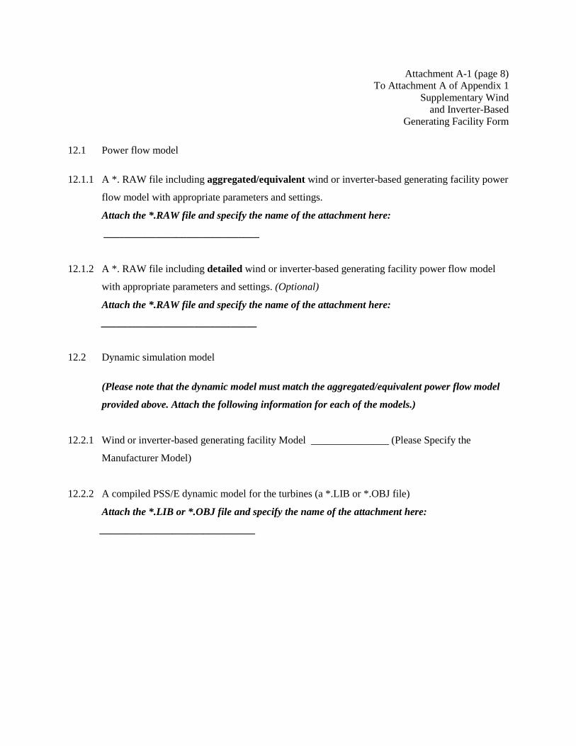
12.1 Power flow model
12.1.1 A *. RAW file including aggregated/equivalent wind or inverter-based generating facility power
flow model with appropriate parameters and settings.
Attach the *.RAW file and specify the name of the attachment here:
______________________________
12.1.2 A *. RAW file including detailed wind or inverter-based generating facility power flow model
with appropriate parameters and settings. (Optional)
Attach the *.RAW file and specify the name of the attachment here:
______________________________
12.2 Dynamic simulation model
(Please note that the dynamic model must match the aggregated/equivalent power flow model
provided above. Attach the following information for each of the models.)
12.2.1 Wind or inverter-based generating facility Model _______________ (Please Specify the
Manufacturer Model)
12.2.2 A compiled PSS/E dynamic model for the turbines (a *.LIB or *.OBJ file)
Attach the *.LIB or *.OBJ file and specify the name of the attachment here:
______________________________

Attachment A-1 (page 9) To Attachment A of Appendix 1
Supplementary Wind and Inverter-Based
Generating Facility Form
12.2.3 A dynamic data file with appropriate parameters and settings for the turbines (typically a *.DYR
file)
Attach the *.DYR file and specify the name of the attachment here:
______________________________
12.2.4 PSS/E wind or inverter-based generating facility model user manual for the WTG
Attach and specify the name of the attachment here:
______________________________
Repeat the above sections from 6 to 12 for each different wind or inverter-based generating
facility model.
13. Power Plant Controller
Will the wind or inverter-based generating facility be equipped with power plant controller,
which has the ability to centrally control the output of the units? Yes__ No__
If yes, please provide:
13.1 Manufacturer model of the power plant controller
_________________________________________
13.2 What are the reactive power control strategy options of the power plant controller?
13.3 Which of the control option stated above is being used in current operation?
________________________________________________

Attachment A-1 (page 10) To Attachment A of Appendix 1
Supplementary Wind and Inverter-Based
Generating Facility Form
13.4 Is the power plant controller able to control the unit terminal voltages to prevent low/high voltage
tripping?
Yes__ No__
Please provide the park controller technical manual from the manufacturer
Attach the file and specify the name of the attachment here:
______________________________
14. Station Transformer
Transformer Name
Nameplate ratings (MVA)
Total number of the main transformer(s)
Voltage, High/Low/Tertiary (kV)
Winding connections, High/Low Tertiary
Available tap positions on high voltage side
Available tap positions on low voltage side
Will the transformer operate as a LTC?
Desired voltage control range if LTC

Attachment A-1 (page 11) To Attachment A of Appendix 1
Supplementary Wind and Inverter-Based
Generating Facility Form
Tap adjustment time (Tap switching delay +
switching time) if LTC
Desired tap position if applicable
Tap adjustment time (Tap switching delay +
switching time)
Impedance Z1, X/R ratio Z1H-L X/R
Z1H-T X/R
Z1T-L X/R
Impedance Z0, X/R ratio Z0H-L X/R
Z0H-T X/R
Z0T-L X/R
15. Dynamic Simulation Model for the Power Plant Controller(s) (if applicable )
(All model files provided under this section 15 should be compatible with Siemens PTI’s PSS/E
version currently in use at ISO New England)
15.1 A compiled PSS/E dynamic model for the power plant controller(s) (a *.LIB or *.OBJ file)
Attach the *.LIB or *.OBJ file and specify the name of the attachment here:
______________________________
15.2 A dynamic data file with appropriate parameters and settings for the power plant controller(s)
(typically a *.DYR file).
Please set the parameters in accordance with the currently used control mode.
Attach the *.DYR file and specify the name of the attachment here:
Attachment A-1 (page 12) To Attachment A of Appendix 1
Supplementary Wind and Inverter-Based
Generating Facility Form
______________________________
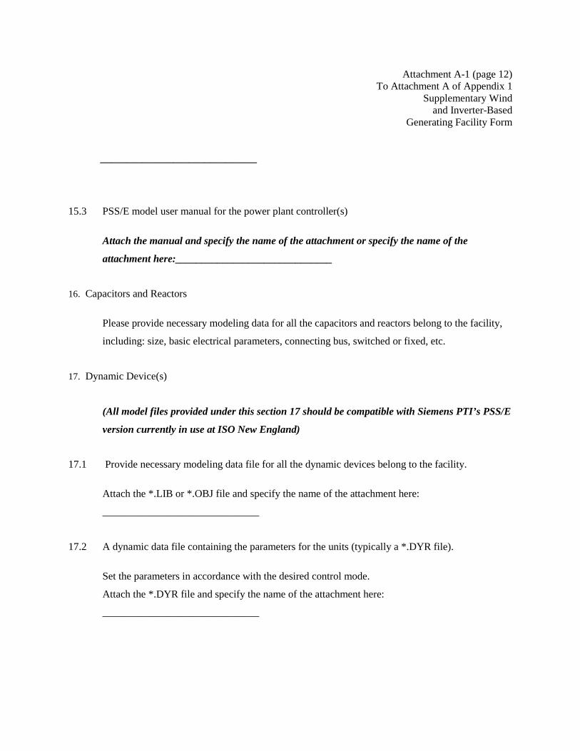
15.3 PSS/E model user manual for the power plant controller(s)
Attach the manual and specify the name of the attachment or specify the name of the
attachment here:______________________________
16. Capacitors and Reactors
Please provide necessary modeling data for all the capacitors and reactors belong to the facility,
including: size, basic electrical parameters, connecting bus, switched or fixed, etc.
17. Dynamic Device(s)
(All model files provided under this section 17 should be compatible with Siemens PTI’s PSS/E
version currently in use at ISO New England)
17.1 Provide necessary modeling data file for all the dynamic devices belong to the facility.
Attach the *.LIB or *.OBJ file and specify the name of the attachment here:
______________________________
17.2 A dynamic data file containing the parameters for the units (typically a *.DYR file).
Set the parameters in accordance with the desired control mode.
Attach the *.DYR file and specify the name of the attachment here:
______________________________
Attachment A-1 (page 13) To Attachment A of Appendix 1
Supplementary Wind and Inverter-Based
Generating Facility Form
18. Collection System/Transformer Tap-Setting Design
Attach a collection system/transformer tap-setting design calculations, consistent with the
requirements in the ISO New England Planning Procedures, that identify the calculations to
support the proposed tap settings for the unit step-up transformers and the station step-up
transformers.
Attached the design document and specify the name of the attachment here:
______________________________________________________
19. Additional Information
Are there any special features available to be implemented to the wind or inverter-based
generating facility? Such as weak grid interconnection solutions, etc.
Specify the available features here:
______________________________________________________
Insert the technical manual for each of the features listed above as objects (display as icons) or
specify the name of the attachment here:
_________________________________________________________
20. Provide PSCAD Model and Documentation for the wind or inverter-based generating facility, the
Power Plant Controller(s) and Other Dynamic Devices for the wind or inverter-based generating
facility.
ISO will determine how much PSCAD work is needed from the wind or inverter-based
generating facility based on its interconnection system conditions.

Attachment A-2 To Attachment A of Appendix 1
Cluster System Impact Study Application Form
CLUSTER SYSTEM IMPACT STUDY APPLICATION FORM
The undersigned Interconnection Customer submits this form to request the inclusion of the Interconnection
Request for its Large Generating Facility in a Cluster Interconnection System Impact Study pursuant to
Section 4.2.3.2.2 of this LGIP.
To be included in a Cluster Interconnection System Impact Study, the following must be submitted together
with this form to the System Operator by the Cluster Entry Deadline:
1. Project Information:
a. Project Name:
b. Queue Position:
c. Is the Interconnection Request contractually associated with an Interconnection Request
for an Elective Transmission Upgrade? Yes ____ No ____
If yes, identify Queue Position of the associated Interconnection Request and provide
evidence of the contractual commitment. Queue Position No.: _____
2. Initial Cluster Participation Deposit as specified in Section 4.2.3.2.2
Applicant Signature
I hereby certify that, to the best of my knowledge, all the information provided in this form is true and
accurate.
For Interconnection Customer:_____________________________Date:_________________________
Attachment B (page 1)
To Appendix 1
Interconnection Request
Technical Data Required For
Interconnection Feasibility Study
The technical data required below must be submitted no later than the date of execution of the
Feasibility Study Agreement pursuant to Section 6.1 of the LGIP.
LARGE GENERATING FACILITY DATA
UNIT RATING
kVA °F Phase to Phase Voltage, kV
Rated Power Factor
Speed (RPM) Connection (e.g. Wye)
Short Circuit Ratio Frequency, Hertz
Stator Amperes at Rated, kVA Field Volts
Max Turbine MW °F
GREATEST UNIT RATING AT AMBIENT TEMPERATURE OF 50oF OR ABOVE
Gross Unit Rating (MW) Gross Lagging (MVAR)
Net Unit Rating (MW) Gross Leading (MVAR)
Station Service (MW) Station Service (MVAR)
Temperature (oF)
DATA (PER UNIT-RATED KVA AND RATED VOLTAGE)
Saturated Reactance
Direct axis positive sequence X”dv
negative sequence X”2v ______
zero sequence X”0v

Attachment B (page 2) To Appendix 1
Interconnection Request Technical Data Required For
Interconnection Feasibility Study
Resistance
Generator AC resistance Ra ______
negative sequence R2 ______
zero sequence R0 ______
Time Constant (seconds)
Three-phase short circuit armature time constant Ta3 _____
CURVES
Provide Saturation, Vee, Reactive Capability, Capacity Temperature Correction curves. Designate
normal and emergency Hydrogen Pressure operating range for multiple curves.
GENERATOR STEP-UP TRANSFORMER DATA RATINGS
Capacity Self-cooled/Maximum Nameplate
/ kVA
Voltage Ratio Generator side/System side/Tertiary
/ kV
Winding Connections Generator side/system side /Tertiary
(Delta or Wye)
/
Fixed Taps Available
Present Tap Setting
Attachment B (page 3) To Appendix 1
Interconnection Request Technical Data Required For
Interconnection Feasibility Study IMPEDANCE
For 2-Winding Transformers
Positive Z1 (on self-cooled kVA rating) % X/R
Zero Z0 (on self-cooled kVA rating) % X/R
IMPEDANCE
For 3-winding transformers
Positive Z1H-L (on self-cooled kVA rating) %, X/R
Z1H-T (on self-cooled kVA rating) %, X/R
Z1L-T (on self-cooled kVA rating) %, X/R
Zero Z0H-L (on self-cooled kVA rating) %, X/R
Z0H-T (on self-cooled kVA rating) %, X/R
Z0L-T (on self-cooled kVA rating) %, X/R
FEEDER IMPEDANCE (Per Unit)
From GSU to Point of Interconnection
Positive R1 + j X1 on 100 MVA base
Zero R0 + j X0 on 100 MVA base

Attachment B (page 4) To Appendix 1
Interconnection Request Technical Data Required For
Interconnection Feasibility Study
WIND GENERATORS
Number of generators to be interconnected pursuant to this Interconnection Request: ________
Elevation:________________________Single Phase________________Three Phase
Inverter manufacturer, model name, number, and version:
List of adjustable setpoints for the protective equipment or software:
For all generator types: A completed fully functioning, public (i.e., non-proprietary, non-confidential)
Siemens PTI’s (“PSSE”) power flow model or other compatible formats, such as IEEE and General
Electric Company Power Systems Load Flow (“PSLF”) data sheet, must be supplied with this Attachment
B. If additional public data sheets are more appropriate to the proposed device then they shall be
provided and discussed at the Scoping Meeting. For all Interconnection Feasibility Studies commencing
after January 1, 2017, all power flow models must be standard library models in PSS/E or applicable
applications. User-models will not be accepted.
Applicant Signature
I hereby certify that, to the best of my knowledge, all the information provided in this Attachment B to
the Interconnection Request is true and accurate.
For Interconnection Customer:___________________________Date:___________________________