Appeal decision Appeal No. 2014-19883 · Appeal decision Appeal No. 2014-19883 ... a propagating...
27
1 / 27 Appeal decision Appeal No. 2014-19883 Belgium Appellant BIOCARTIS NV Tokyo, Japan Patent Attorney EINSEL FELIX-REINHARD Tokyo, Japan Patent Attorney KUNO, Takuya The case of appeal against the examiner's decision of refusal of Japanese Patent Application No. 2012-505017, entitled "OPTICAL DETECTION SYSTEM FOR MONITORING rtPCR REACTION" (the application published on October 21, 2010, International Publication No. WO 2010/118541, national publication of the translated version (of PCT application) on October 11, 2012, National Publication of International Patent Application No. 2012-524242) has resulted in the following appeal decision. Conclusion The appeal of the case was groundless. Reason No. 1 History of the procedures The application was filed on April 9, 2010 (priority claim under the Paris Convention received by a foreign patent office on April 15, 2009 (EP) European Patent Office) as an international filing date. The reason for refusal was notified on February 4, 2014, and a written opinion and a written amendment were submitted on May 9, 2014. The examiner's decision to dismiss amendment was made on May 28, 2014, and a copy of the decision of refusal was transmitted to the appellant on June 2, 2014. An appeal against the examiner's decision of refusal was requested on October 2, 2014, and an amendment was made at the same time.
-
Upload
duongkhanh -
Category
Documents
-
view
216 -
download
1
Transcript of Appeal decision Appeal No. 2014-19883 · Appeal decision Appeal No. 2014-19883 ... a propagating...

1 / 27
Appeal decision Appeal No. 2014-19883 Belgium Appellant BIOCARTIS NV Tokyo, Japan Patent Attorney EINSEL FELIX-REINHARD Tokyo, Japan Patent Attorney KUNO, Takuya The case of appeal against the examiner's decision of refusal of Japanese Patent Application No. 2012-505017, entitled "OPTICAL DETECTION SYSTEM FOR MONITORING rtPCR REACTION" (the application published on October 21, 2010, International Publication No. WO 2010/118541, national publication of the translated version (of PCT application) on October 11, 2012, National Publication of International Patent Application No. 2012-524242) has resulted in the following appeal decision. Conclusion The appeal of the case was groundless. Reason No. 1 History of the procedures The application was filed on April 9, 2010 (priority claim under the Paris Convention received by a foreign patent office on April 15, 2009 (EP) European Patent Office) as an international filing date. The reason for refusal was notified on February 4, 2014, and a written opinion and a written amendment were submitted on May 9, 2014. The examiner's decision to dismiss amendment was made on May 28, 2014, and a copy of the decision of refusal was transmitted to the appellant on June 2, 2014. An appeal against the examiner's decision of refusal was requested on October 2, 2014, and an amendment was made at the same time.

2 / 27
No. 2 Decision to dismiss amendment on the written amendment made on October 2, 2014 [Conclusion of Decision to Dismiss Amendment] The written amendment (hereinafter referred to as "The Amendment") made on October 2, 2014 shall be dismissed. [Reason for Decision to Dismiss Amendment] 1 Details of the Amendment The amendment includes in part amending the description (refer to (1) below) of Claim 1 of the scope of claims described in the written amendment submitted on May 9, 2014 to the description (refer to (2) below) of Claim 1 of the scope of claims described in the written amendment submitted on October 2, 2014. (1) Description of Claim 1 of the scope of claims before the amendment The description of Claim 1 of the scope of claims described in the written amendment submitted on May 9, 2014 is as follows. "1. An optical multiplexing system (100) for detecting sample components in at least two different sample chambers (101-104), the optical multiplexing system comprising: a first optical unit (106) and a second optical unit (107); wherein the first optical unit and the second optical unit are spatially separated from each other; wherein the first optical unit comprises a first light source (108) and a first detector (109); wherein the second optical unit comprises a second light source (110) and a second detector (111); wherein the optical multiplexing system is adapted for receiving at least two sample chambers to be received at positions corresponding to each of the optical units so that the first and the second light sources respectively illuminate at least one sample chamber and the first detector and the second detector respectively receive light from at least one sample chamber; wherein the system is adapted for a relative movement (113) of the first optical unit and second optical unit relative to at least the two sample chambers to make it possible to align the first optical unit to a second sample chamber and align the second

3 / 27
optical unit to a first sample chamber; and wherein each time when the relative movement is generated, by each optical unit and each sample chamber being aligned, a propagating path of a photon emitted from each optical unit is matched to an optical access to each sample chamber." (2) Description of Claim 1 of the scope of claims after the amendment The description of Claim 1 of the scope of claims described in the written amendment submitted on October 2, 2014 is as follows. "1. An optical multiplexing system (100) for detecting sample components in at least two different sample chambers (101-104), the optical multiplexing system comprising: a first optical unit (106) for detecting a product of a first polymerase chain reaction (PCR); a second optical unit (107) for detecting a product of a second polymerase chain reaction (PCR); a first heater associated with a first sample chamber of at least the two different sample chambers, the first heater forming a first temperature lapse in the first sample chamber; a second heater associated with a second sample chamber of at least the two different sample chambers, the second heater forming a second temperature lapse in the second sample chamber; and a control unit for receiving a PCR protocol, wherein the first optical unit and the second optical unit are spatially separated from each other, wherein the first optical unit comprises a first light source (108) and a first detector (109); wherein the second optical unit comprises a second light source (110) and a second detector (111), wherein the optical multiplexing system is adapted for receiving at least two sample chambers to be received at positions corresponding to the first optical unit and the second optical unit so that (a) the first and the second light sources respectively illuminate at least the two sample chambers simultaneously, and (b) the first detector and the second detector respectively receive light from at least the two sample chambers simultaneously, wherein the first optical unit and the second optical unit simultaneously perform a first optical measurement and a second optical measurement by using two different optical wavelengths at respective chambers of the first optical unit and the
4 / 27
second optical unit, which are spatially separated from each other, wherein the system is adapted for a relative movement (113) of the first optical unit and the second optical unit relative to at least the two sample chambers to make it possible to align the first optical unit to the second sample chamber and align the second optical unit to the first sample chamber, wherein each time when the relative movement is generated, by each optical unit and each sample chamber being aligned, a propagating path of a photon emitted from each optical unit is matched to an optical access to each sample chamber, wherein the control unit is adapted for controlling the first heater and the second heater so that real-time PCR reactions are generated at the first sample chamber and the second sample chamber in accordance with the PCR protocol, wherein the control unit is adapted for a relative movement of the first optical unit and the second optical unit relative to at least the two sample chambers to simultaneously quantify amplified target DNA molecules." (Note by the body: underlined parts correspond to amended parts.) 2 Propriety of the amendment (1) Purpose of the Amendment The amendment is, in Claim 1 of the scope of claims, "a control unit for receiving a PCR protocol," and includes to add a "controller unit" "for controlling the first heater and the second heater so that real-time PCR reactions are generated at the first sample chamber and the second sample chamber in accordance with the PCR protocol, wherein the control unit is adapted for a relative movement of the first optical unit and the second optical unit relative to at least the two sample chambers to simultaneously quantify amplified target DNA molecules." However, since the above-described amendment matters newly add a "controller unit" as a configuration element of the "optical multiplexing system," it corresponds to an external addition of the configuration, and it cannot be said that it is derived by restricting by limitation a part of the configuration of Claim 1 before the amendment. Therefore, the amendment does not correspond to an amendment having an object of restricting the scope of claims in accordance with the provisions of Article 17-2(5)(ii) of the Patent Act.
5 / 27
The amendment does not correspond to any of the deletion of claim of Article 17-2(5)(i) of the Patent Act, the correction of errors of (iii), and the clarification of an ambiguous statement of (iv), either. Therefore, the amendment regarding Claim 1 of the scope of claims after the amendment corresponds to none of the items of Article 17-2(5) of the Patent Act. (2) Consideration on Independent requirements for patentability Although as judged in the above-described "(1) Purpose of amendment," the above-described amendment includes an amendment for other purposes and violates the provisions of the Patent Act, by assuming that the above-described amendment has an objective of restricting the scope of claims in accordance with the provisions of Article 17-2(5)(ii) of the Patent Act as the appellant claims in the request for appeal, an examination is carried out on whether the appellant can be granted a patent for the invention (hereinafter referred to as the "Amended Invention") according to Claim 1 of the scope of claims after the amendment independently at the time of patent application (whether to be compatible with the provisions of Article 126(7) of the Patent Act which is applied mutatis mutandis pursuant to the provisions of Article 17-2(6) of the Patent Act). A On the Cited Document (A) Matters described in the Cited Document The following matters are described with reference to the drawings in National Publication of International Patent Application No. 2008-537594 (hereinafter referred to the "Cited Document"), which is a publication, distributed before the priority date of the application, cited for reasons for refusal stated in the examiner's decision. (The underlines were added by the body to the description directly used for the recognition of the Cited Invention.) (C-1) "[0007] In general, the invention relates to techniques for the detection of multiple target species in real-time PCR (polymerase chain reaction), referred to herein as multiplex PCR. In particular, there is described a multiplex fluorescence detection device that incorporates a plurality of optical modules. Each of the optical modules may be optimized for detection of a respective fluorescent dye at a discrete wavelength

6 / 27
band. In other words, the optical modules may be used to interrogate multiple, parallel reactions at different wavelengths. The reaction may, for example, occur within a single process chamber (e.g., well) of a rotating disk. Additionally, each optical module may be removable to quickly change the detection capabilities of the device." (C-2) "[0011] In an additional embodiment, a method comprises rotating a disk having a plurality of process chambers each having a plurality of species that emit fluorescent lamp light (note by the body: considered to be an error of "fluorescent light") at different wavelengths, exciting the disk with a plurality of light beams to produce a plurality of emitted fluorescent lamp light beams (note by the body: considered to be an error of "emitted fluorescent light beams"), capturing the fluorescent lamp light beams (note by the body: considered to be an error of "fluorescent light beams") with a plurality of different optical modules, wherein the modules are optically configured for the different wavelengths, containing the plurality of different modules within a housing." (C-3) "[0013] While the device may be capable of conducting real-time PCR, the device may be capable of analyzing any type of biological reaction while it occurs. The device may be able to modulate the temperature of each reaction independently or as a selected group, and the device may be able to support multiple stages of reactions by including a valve between two chambers. This valve may be opened during reactions through the use of a laser which delivers a burst of energy to the valve. (C-4) "[0016] FIG. l is a block diagram illustrating an exemplary embodiment of a multiplex fluorescence detection device 10. In the illustrated example, the device 10 has four optical modules 16 that provide four "channels" for optical detection of four different dyes. In particular, the device 10 has four optical modules 16 that excite different regions of rotating disk 13 at any given time, and collect emitted fluorescent lamp light energy (note by the body: considered to be an error of "fluorescent light energy”) at different wavelengths from the dyes. As a result, the modules 16 may be used to interrogate multiple, parallel reactions occurring within the sample 22." (C-5) "[0018]

7 / 27
Although a single sample 22 is illustrated, the disk 13 may contain a plurality of chambers holding samples. Optical modules 16 may interrogate some or all of the different chambers at different wavelengths. In one embodiment, the disk 13 includes 96 chambers space around a circumference of the disk 13. With a 96 chamber disk and four optical modules 16, the device 10 may be capable of acquiring data from 384 different species." (C-6) "[0020] As illustrated in FIG. 1, each of optical modules 16 may be coupled to one leg of a fiber optic bundle 14. The fiber optic bundle 14 provides a flexible mechanism for collection of fluorescent signals from optical modules 16 without loss of sensitivity. In general, a fiber optic bundle comprises multiple optical fibers laid side by side and bonded together at the ends and encased in a flexible protective jacket. Alternatively, the fiber optic bundle 14 may comprise a smaller number of discrete, large diameter multi- mode fibers, either glass or plastic, having a common end. For example, for a four- optical module device, the fiber optic bundle 14 may comprise four discrete multimode fibers, each having a 1 mm core diameter. The common end of the bundle contains the four fibers bound together. In this example, the aperture of the detector 18 may be 8 mm, which is more than sufficient for coupling to the four fibers." [0021] In this example, the fiber optic bundle 14 couples the optical modules 16 to a single detector 18. The optical fibers carry the fluorescent lamp light (note by the body: considered to be an error of fluorescent light) collected by optical modules 16 and effectively deliver the captured light to the detector 18. In one embodiment, the detector 18 is a photomultiplier tube (note by the body: considered to be an error of "photomultiplier tube"). In another embodiment, the detector may include multiple photomultiplier elements (note by the body: considered to be an error of "multiple photomultiplier elements"), one for each optical fiber, within the single detector. In other embodiments, one or more solid-state detectors may be used. (C-7) "[0026] In the example of FIG. 1, samples 22 are contained in chambers of the disk 13, which is mounted on a rotating platform under the control of a control unit 23. A slot sensor trigger 27 provides an output signal utilized by the control unit 23 and a data acquisition device 21 for synchronizing data acquisition with chamber position during disk rotation. The slot sensor trigger 27 may be a mechanical or optical sensor. For

8 / 27
example, the sensor may be a laser which sends a beam of light to the disk 13 and the control unit 23 uses a sensor detecting light passing through a slot in the disk 13 to locate the chambers on the disk. In other embodiments, the disk 13 may include a tab, protrusion, or reflective surface in addition to or in place of the slot. The slot sensor trigger 27 may use any physical structure or mechanism to locate the radial position of the disk 13 as it rotates. The optical modules 16 may be physically mounted above a rotating platform 25. As a result, optical modules 16 are overlapped with different chambers at any one time." (C-8) "[0027] The detection device 10 also includes a heating element (not shown) for modulating the temperature of the sample 22 on the disk 13. The heating element may comprise a cylindrical halogen bulb contained within a reflective enclosure. The reflective chamber is shaped to focus radiation from the bulb onto a radial section of the disk 13. Generally, the heated area of disk 13 would resemble a ring as the disk 13 spins. In this embodiment, the shape of the reflective enclosure may be a combination of elliptical and spherical geometries that allow precise focusing. In other embodiments, the reflective enclosure may be of a different shape or the bulb may broadly irradiate a larger area. In other embodiments, the reflective enclosure may be shaped to focus the radiation from the bulb onto a single area of the disk 13, such as a single process chamber containing a sample 22. [0028] In some embodiments, the heating element may heat air and force the hot air over one or more samples to modulate the temperature. Additionally, the samples may be heated directly by the disk. In this case, the heating element may be located in the platform 25 and thermally couple to the disk 13. Electrical resistance within the heating element may heat a selected region of the disk as controlled by the control unit 23. For example, a region may contain one or more chambers, possibly the entire disk. An exemplary heating element for use with the rotating disk 13 is described in U.S. Patent Application No. 11/174,691, entitled "HEATING ELEMENT FOR A ROTATING MULTIPLEX FLUORESCENCE DETECTION DEVICE," filed on July 5, 2005." (C-9) "[0032] The data acquisition device 21 may collect data from the device 10 for each dye either sequentially or in parallel. In one embodiment, the data acquisition device

9 / 27
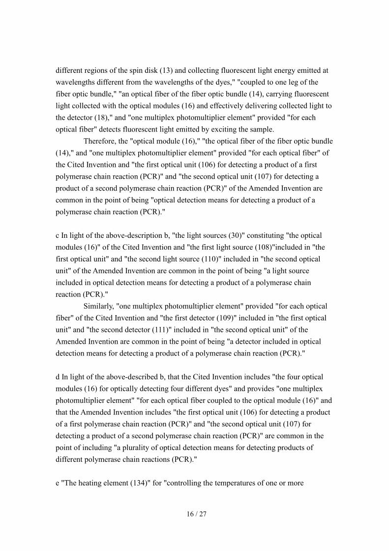
21 collects the data from the optical modules 16 in sequence, and corrects the spatial overlap by a trigger delay for each one of the optical modules measured from the slot sensor trigger 27." (C-10) "[0034] For real-time PCR, fluorescence is used to measure the amount of amplification by one of three general techniques. The first technique is the use of a dye, such as Sybr Green (Molecular Probes, Eugene, Oregon), whose fluorescence increases upon binding to double-stranded DNA. The second technique uses fluorescently labeled probes whose fluorescence changes when bound to the amplified target sequence (hybridization probes, hairpin probes, etc.). This technique is similar to using a double- stranded DNA binding dye, but is more specific because the probe will bind only to a certain section of the target sequence. The third technique is the use of hydrolysis probes (Taqman(TM), Applied BioSystems, Foster City California), in which the exonuclease activity of the polymerase enzyme cleaves a quencher molecule from the probe during the extension phase of PCR, making it fluorescently active." (C-11) "[0091] FIG. 8 is a functional block diagram of the multiplex fluorescence detection device 10. In particular, FIG. 8 indicates the electrical connections between device components and the general paths of light through the components. In the example of FIG. 8, device 10 includes at least one processor 122 or other control logic, a memory 124, a disk motor 126, a light source (30), an excitation filter 34, a lens 38, a detection filter 40, a collecting lens (42), the detector 18, the slot sensor trigger 27, a communication interface 130, a heating element (134), a laser 136, and a power source 132. As shown in FIG 3, the lens 38 and the collecting lens (42) need not be electrically connected to another component. Further, the light source (30), the filters 34 and 40, the lens 38, and the collecting lens (42) are representative of one optical module 16. Although not illustrated in FIG. 8, the device 10 may contain additional optical modules 16, as described previously. In that case, each additional optical module may include components arranged substantially similarly as to those shown in FIG. 8. [0092] Light follows a certain path through several components in FIG 8. Once light is emitted by the light source (30), it enters the excitation filter 34 and leaves as light of a discrete wavelength. It then passes through the lens 38 where it leaves the detection
10 / 27
device 10 and excites the sample 22 within a process chamber (not shown). The sample 22 responds by fluorescing at a different wavelength, at which time this fluorescent lamp light (note by the body: considered to be an error of "fluorescent light") enters the lens 38 and is filtered by the detection filter 40. The filter 40 removes background light of wavelengths outside of the desired fluorescence from the sample 22. The remaining light is sent through the collecting lens (42) and enters a leg of the fiber optic bundle 14 before being detected by the detector 18. The detector 18 subsequently amplifies the received light signal. [0093] The processor 122, the memory 124, and the communication interface 130 may be part of the control unit 23. The processor 122 controls the disk motor 126 to rotate or the spin disk 13 as needed to collect fluorescence information or move fluid through the disk 13. The processor 122 may use disk position information received from the slot sensor trigger 27 to identify the location of chambers on a rotating time disk 13 (note by the body: considered to be an error of "a disk 13 during rotation”) and synchronize the acquisition of florescence data received from the disk. [0094] The processor 122 may also control when the light source (30) within the optical module 16 is powered on and off. In some embodiments, the processor 122 controls the excitation filter 34 and the detection filter 40. Depending on the sample being illuminated, the processor 122 may change the filter to allow a different wavelength of excitation light to reach the sample or a different wavelength of fluorescence to reach the collecting lens (42). In some embodiments, one or both filters may be optimized for the light source (30) of the particular optical module 16 and be unable to be changed by the processor 122. [0095] The collecting lens (42) is coupled to one leg of the fiber bundle 14 that provides an optical path for the light from the collecting lens to the detector 18. The processor 122 may control the operation of the detector 18. While the detector 18 may constantly be detecting all light, some embodiments may utilize other acquisition modes. The processor 122 may determine when the detector 18 collects data and may programmatically set other configuration parameters of the detector 18. In one embodiment, the detector 18 is a photomultiplier tube that captures fluorescence information from light provided by the collecting lens (42). In response, the detector 18 produces an output signal 128 (e.g., an analog output signal) representative of the received light. Although not shown in FIG. 8, the detector 18 may concurrently
11 / 27
receive light from the other optical modules 16 of the device 10. In that case, the output signal 128 electrically represents a combination of the optical input received by the detector 18 from the various optical modules 16. [0096] The processor 122 may also control data flow from the device 10. Data such as sampled fluorescence from the detector 18, temperature of the samples from the heating element (134) and related sensors, and disk rotation information may be stored into a memory 124 for analysis. The processor 122 may comprise any one or more of a microprocessor, a digital signal processor (DSP), an application specific integrated circuit (ASIC), a field-programmable gate array (FPGA), or other digital logic circuitry. Moreover, the processor 122 provides an operating environment for firmware, software, or combinations thereof, stored on a computer-readable medium, such as the memory 124. [0097] The memory 124 may include one or more memories for storing a variety of information. For example, one memory may contain specific configuration parameters and executable instructions, and one may contain collected data. Therefore, the processor 122 may use data stored in the memory 124 for controlling device operation and calibration. The memory 124 may include any one or more of a random access memory (RAM), read-only memory (ROM), electronically-erasable programmable ROM (EEPROM), flash memory, or the like. [0098] The processor 122 may additionally control the heating element (134). Based upon the instructions contained within the memory 124, the heating element (134) may be selectively driven to control the temperature of one or more chambers according to desired heating profiles. Generally, the heating element heats one radial section of disk 13 as the disk spins. The heating element 134 may comprise a halogen bulb and a reflector for focusing heating energy on a specific area of the disk 13. In other embodiments, the heating element (134) may heat one or more chambers sequentially. This embodiment would require the disk 13 to be stationary while a chamber is heated. In any embodiment, the heating element (134) may be capable of turning on and off extremely quickly as needed." (C-12) "[0101] Communications with the detection device 10 may also be accomplished by radio frequency (RF) communication or a local area network (LAN) connection.
12 / 27
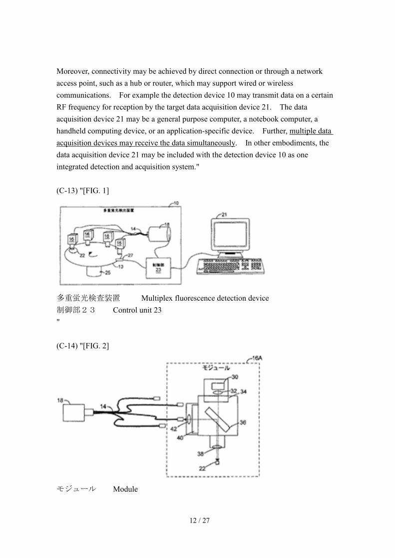
Moreover, connectivity may be achieved by direct connection or through a network access point, such as a hub or router, which may support wired or wireless communications. For example the detection device 10 may transmit data on a certain RF frequency for reception by the target data acquisition device 21. The data acquisition device 21 may be a general purpose computer, a notebook computer, a handheld computing device, or an application-specific device. Further, multiple data acquisition devices may receive the data simultaneously. In other embodiments, the data acquisition device 21 may be included with the detection device 10 as one integrated detection and acquisition system." (C-13) "[FIG. 1]
多重蛍光検査装置 Multiplex fluorescence detection device 制御部23 Control unit 23 " (C-14) "[FIG. 2]
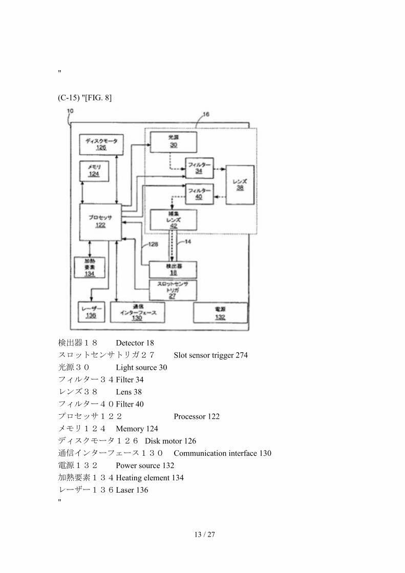
モジュール Module
13 / 27
" (C-15) "[FIG. 8]
検出器18 Detector 18 スロットセンサトリガ27 Slot sensor trigger 274 光源30 Light source 30 フィルター34 Filter 34 レンズ38 Lens 38 フィルター40 Filter 40 プロセッサ122 Processor 122 メモリ124 Memory 124 ディスクモータ126 Disk motor 126 通信インターフェース130 Communication interface 130 電源132 Power source 132 加熱要素134 Heating element 134 レーザー136 Laser 136 "

14 / 27
(A) On the invention described in the Cited Document a In view of the above-described summarized matter (C-13), it can be recognized that a plurality of "optical modules (16)" are spatially separated from each other. b In light of the above-described summarized matters (C-1) to (C-15) and the above-described a, the Cited Document can be recognized as describing inventions as follows (hereinafter referred to as the "Cited Invention"), "A multiplex fluorescence detection device (10), for detecting multiple target species in a real-time PCR (polymerase chain reaction), at least including: a processor (122) or other control logics; a memory (124); a spin disk (13); a light source (30); an excitation filter (34); a lens (38); a detection filter (40); a collecting lens (42); a detector (18); a slot sensor trigger (27); and a heating element (134), wherein the light source (30), the filters (34) and (40), the lens (38), and the collecting lens (42) represent one optical module (16), the spin disk (13) including: a plurality of chambers holding a sample containing a plurality of species emitting fluorescent light with individual different wavelengths; and four optical modules (16), spatially separated from one another, for optically detecting four different dyes, each individual optical module (16) capable of interrogating different chambers for different wavelengths, for exciting different regions of the spin disk (13) during an arbitrary predetermined time, collecting fluorescent light energy emitted at wavelengths different from the wavelengths of the dyes, coupled to one leg of the fiber optic bundle (14), an optical fiber of the fiber optic bundle (14), carrying fluorescent light collected with the optical modules (16) and effectively delivering collected light to the detector (18), the detector (18) including one multiplex photomultiplier element for each optical fiber, the slot sensor trigger (27), synchronizing data acquisition with a chamber position during disk rotation, outputting an output signal to be used by a data acquisition device (21), a control unit (23), positioning a radial position of the spin disk (13), and as a result, the optical modules (16), physically mounted above the rotating platform, are simultaneously overlapped with different chambers, the heating element (134), being used for modulating the temperature of a

15 / 27
sample (22) on the disk (13), for heating a selected region of the spin disk (13), the processor (122), for using the disk position information received from the slot sensor trigger (27), identifying the locations of chambers on the spin disk (13), synchronizing acquisition of the fluorescent light data received from the disk, selectively driving the heating element (134) based upon the instructions contained within the memory (124), controlling temperatures of one or more chambers with desired heating profiles, the optical modules (16), being simultaneously activated for concurrently interrogating the sample (22), the detector (18), simultaneously receiving light from other optical modules (16) of the device (10), the data acquisition device (21), collecting in parallel data from the device (10) for each dye, the multiplex fluorescence detection device capable of modulating a temperature for each reaction independently or as a selected group." B Comparison / Judgment (A) Comparison between Amended Invention and Cited Invention Below, the Amended Invention and the Cited Invention are compared. a The "multiplex fluorescence detection device (10)" of the Cited Invention is a device for "exciting different regions of the spin disk (13) and collecting fluorescent light energy emitted at wavelengths different from the wavelengths of the dyes" "including a plurality of chambers holding samples containing a plurality of species emitting fluorescent light with individually different wavelengths," for detecting with "the detector (18)." Therefore, "the multiplex fluorescence detection device (10)" of the Cited Invention corresponds to "the optical multiplexing system (100), for detecting a plurality of sample components in at least two different sample chambers (101-104)" of the Amended Invention. b The Cited Invention is "the multiplex fluorescence detection device (10), for detecting multiple target species in real-time PCR (polymerase chain reaction)." Furthermore, the "optical modules (16)" of the Cited Invention are for "exciting
16 / 27
different regions of the spin disk (13) and collecting fluorescent light energy emitted at wavelengths different from the wavelengths of the dyes," "coupled to one leg of the fiber optic bundle," "an optical fiber of the fiber optic bundle (14), carrying fluorescent light collected with the optical modules (16) and effectively delivering collected light to the detector (18)," and "one multiplex photomultiplier element" provided "for each optical fiber" detects fluorescent light emitted by exciting the sample. Therefore, the "optical module (16)," "the optical fiber of the fiber optic bundle (14)," and "one multiplex photomultiplier element" provided "for each optical fiber" of the Cited Invention and "the first optical unit (106) for detecting a product of a first polymerase chain reaction (PCR)" and "the second optical unit (107) for detecting a product of a second polymerase chain reaction (PCR)" of the Amended Invention are common in the point of being "optical detection means for detecting a product of a polymerase chain reaction (PCR)." c In light of the above-description b, "the light sources (30)" constituting "the optical modules (16)" of the Cited Invention and "the first light source (108)"included in "the first optical unit" and "the second light source (110)" included in "the second optical unit" of the Amended Invention are common in the point of being "a light source included in optical detection means for detecting a product of a polymerase chain reaction (PCR)." Similarly, "one multiplex photomultiplier element" provided "for each optical fiber" of the Cited Invention and "the first detector (109)" included in "the first optical unit" and "the second detector (111)" included in "the second optical unit" of the Amended Invention are common in the point of being "a detector included in optical detection means for detecting a product of a polymerase chain reaction (PCR)." d In light of the above-described b, that the Cited Invention includes "the four optical modules (16) for optically detecting four different dyes" and provides "one multiplex photomultiplier element" "for each optical fiber coupled to the optical module (16)" and that the Amended Invention includes "the first optical unit (106) for detecting a product of a first polymerase chain reaction (PCR)" and "the second optical unit (107) for detecting a product of a second polymerase chain reaction (PCR)" are common in the point of including "a plurality of optical detection means for detecting products of different polymerase chain reactions (PCR)." e "The heating element (134)" for "controlling the temperatures of one or more
17 / 27
chambers with desired heating profiles" of the Cited Invention and "the first heater related to the first sample chamber of at least two different sample chambers," "the first heater, for forming the first temperature lapse in the first sample chamber" and "the second heater related to the second sample chamber of at least two different sample chambers," "the second heater, for forming the second temperature lapse in the second sample chamber" of the Amended Invention are common in the point of being "a heater, related to a sample chamber, the heater, for forming a predetermined temperature lapse." f Since "the multiplex fluorescence detection device" of the Cited Invention is so configured that "the spin disk (13)" "includes a plurality of chambers holding samples containing a plurality of species emitting fluorescent light with individual different wavelengths," "includes four optical modules (16) for optically detecting four different dyes and the individual optical module (16) is capable of interrogating different chambers with different wavelengths," it can be said that in "the plurality of chambers" of "the spin disk (13)," different polymerase chain reactions are occurring. Furthermore, since the Cited Invention describes that "with desired heating profiles by selectively driving the heating element (134)," "the chamber temperatures are controlled," and "a temperature of each reaction can be independently modulated," it is apparent that "a heating element (134)" is provided for each of the plurality of chambers in which different polymerase chain reactions occur, and a temperature of each of "the chambers" is controlled with a temperature profile corresponding to each polymerase chain reaction. Therefore, in light of the above-described e, the Cited Invention including the plurality of "heating elements (134)" so as to be compatible with the plurality of "chambers" in which different polymerase chain reactions occur, and the Amended Invention including: "a first heater related to the first sample chamber of at least the two different sample chambers, the first heater, for forming a first temperature lapse in the first sample chamber; a second heater related to the second sample chamber of at least the two different sample chambers, the second heater, for forming a second temperature lapse in the second sample chamber, are common in the point of being "a heater provided for each of at least two different sample chambers, the plurality of heaters, each heater, for forming a predetermined temperature lapse in a corresponding sample chamber." g "The processor (122)" of the Cited Invention, "for controlling the temperatures of one or more chambers with desired heating profiles by selectively driving the heating
18 / 27
element (134) based upon the instructions contained within the memory (124)" corresponds to "the control unit for receiving a PCR protocol" of the Amended Invention. h The Cited Invention describing that "for concurrently interrogating the sample (22), the optical modules (16) are simultaneously activated and the detector (18) simultaneously receives light from the other optical modules (16) of the device (10), and the Amended Invention describing that "(a) with the first light source and the second light source, at least the two sample chambers are simultaneously illuminated, and (b) with the first detector and the second detector, light from at least the two sample chambers is simultaneously received" are common in the point of "(a) with light sources of a plurality of optical detection means, each of a plurality of sample chambers is simultaneously illuminated, and (b) with detectors of a plurality of optical detection means, light from each of the plurality of sample chambers is simultaneously received." i The Cited Invention describing that "the four optical modules (16)" are spatially separated from each other, and the Amended Invention describing that "the first optical unit and the second optical unit" "are spatially separated from each other" are common in the point of "a plurality of optical detection means being spatially separated from each other." j In light of the above-described i, the Cited Invention including "the four optical modules (16)," "spatially separated from one another," "for interrogating different chambers with different wavelengths," wherein "the control unit (23) positions the radial position of the spin disk (13), and as a result, the optical modules (16) are simultaneously overlapped with different chambers," "for concurrently interrogating the sample (22)," "the optical modules (16) are simultaneously activated," "the detector (18) simultaneously receives light from the other optical module (16) of the device (10)," and "the data acquisition device (21) collects in parallel data from the device (10) for each dye" and the Amended Invention describing that "at least the two sample chambers are received at positions corresponding to the first optical unit and the second optical unit, and the first optical unit and the second optical unit simultaneously perform the first optical measurement and the second optical measurement by using two different optical wavelengths at respective chambers of the first optical unit and the second optical unit, which are spatially separated from each other" are common in the point of "receiving at least two sample chambers at a position corresponding to each optical
19 / 27
detection means, wherein each optical detection means simultaneously performs a plurality of optical measurements by using different optical wavelengths at each sample chamber of each optical detection means, which are spatially separated from each other." k The Cited Invention describing that "the control unit (23) positions the radial position of the spin disk (13), and as a result, the optical modules (16), physically mounted above the rotating platform, are simultaneously overlapped with different chambers," "for concurrently interrogating the sample (22)," "the optical modules (16) are simultaneously activated," and "the detector (18) simultaneously receives light from the other optical module (16) of the device (10)", and the Amended Invention describing "being adapted for a relative movement (113) of the first optical unit and the second optical unit relative to at least the two sample chambers to make it possible to align the first optical unit to the second sample chamber and align the second optical unit to the first sample chamber, wherein each time when the relative movement is generated, by each optical unit and each sample chamber being aligned, a propagating path of a photon emitted from each optical unit is matched to an optical access to each sample chamber" are common in the point of "being adopted for a relative movement of a plurality of optical detection means relative to at least two sample chambers to make it possible to align each optical detection means to a corresponding sample chamber, wherein each time when the relative movement is generated, by each optical detection means and each sample chamber being aligned, a propagating path of a photon emitted from each optical unit is matched to an optical access to each sample chamber." l Since the Cited Invention is "the multiplex fluorescence detection device (10), for detecting multiple target species during a real-time PCR (polymerase chain reaction)," it is apparent that "acquisition of the fluorescent light data" means "acquisition of data of amplified target DNA molecules." Then, in light of the above-described f, the Cited Invention describing that "the processor (122)" "controls the temperatures of one or more chambers with desired heating profiles by selectively driving the heating element (134) based upon the instructions contained within the memory (124)," "identifies the locations of chambers on the spin disk (13)," and "synchronizes acquisitions of the fluorescent light data" with "the optical modules (16)" "simultaneously overlapped with different chambers," and the Amended Invention describing that the controller unit controls the first heater and the second heater so that a real-time PCR reaction is generated at the first sample chamber and the second sample chamber in accordance
20 / 27
with the PCR protocol, wherein the control unit is adapted for a relative movement of the first optical unit and the second optical unit relative to at least the two sample chambers to simultaneously quantify amplified target DNA molecules" are common in the point that a controller unit controls a plurality of heaters so that real-time PCR reactions are generated at a plurality of sample chambers in accordance with the PCR protocol, wherein the control unit is adapted for a relative movement of the plurality of optical detection means relative to at least the two sample chambers to simultaneously acquire data of amplified target DNA molecules." m Therefore, the Amended Invention and the Cited Invention correspond in the following corresponding features and differ in the following different features. <<Corresponding features>> "An optical multiplex system for detecting a plurality of sample components in at least two different sample chambers, the optical multiplex system comprising: a plurality of optical detection means for detecting products of different polymerase chain reactions (PCR); a plurality of heaters provided at each of at least two different sample chambers, each heater forming a predetermined temperature lapse at a corresponding sample chamber; and a control unit for receiving a PCR protocol, wherein, the plurality of optical detection means are spatially separated from one another, each of the plurality of optical detection means includes a light source and a detector, the optical multiplex system being so configured that (a) light sources of the plurality of optical detection means simultaneously illuminate a plurality of respective sample chambers, and (b) at least two sample chambers are received at positions corresponding to respective optical detection means so that detectors of the plurality of optical detection means simultaneously receive light from the plurality of sample chambers, wherein a plurality of optical detection means simultaneously perform a plurality of respective optical measurements by using respective different optical wavelengths at respective sample chambers of the respective optical detection means spatially separated from one another, and a relative movement of the plurality of optical detection means relative to at least two sample chambers to make it possible to align each optical detection means to a corresponding sample chamber,

21 / 27
wherein, each time when the relative movement is generated, by each optical detection means and each sample chamber being aligned, a propagating path of a photon emitted from each optical detection means is matched to an optical access to each sample chamber. wherein the control unit is adapted for controlling the plurality of chambers so that real-time PCR reactions are generated at the plurality of sample chambers in accordance with a PCR protocol, wherein the control unit is adapted for a relative movement of the plurality of optical detection means relative to at least two sample chambers to simultaneously acquire amplified target DNA molecule data." <<Different feature 1>> As optical detection means for detecting products of different polymerase chain reactions (PCR), the Amended Invention includes two "optical units," while the Cited Invention includes four sets of "optical modules (16)" and "multiplex photomultiplier elements" provided for each optical module. <<Different feature 2>> The Amended Invention includes "the first detector (109)" for "the first optical unit (106)" and "the second detector (111)" for "the second optical unit (107)," while the Cited Invention includes no detector for "the optical modules (16)," but "the optical modules (16)" are coupled to "the detector (18)," which is "a multiplex photomultiplier element" through respective optical fibers. <<Different feature 3>> While the Amended Invention performs operations to "quantify amplified target DNA molecules," it is unknown whether the Cited Invention performs operations to quantify amplified target DNA molecules. (B) Judgment by the body a Examination on different features (a) Different feature 1 In configuring an "optical multiplexing system", how many optical detection means is to be provided is a matter to be determined by the number of polymerase chain reactions (PCR) to be detected.

22 / 27
Therefore, it can be said that, in the Cited Invention, making the number of detection means of products of polymerase chain reactions (PCR) to be 2 can be exercised accordingly by a person skilled in the art based on the request on the design of the device. (b) Different feature 2 In the technical field of "fluorescent light analysis devices," to include in one optical module an excitation light source and a fluorescent light detector is a well-known device configuration technology, as respectively disclosed, for instance, in National Publication of International Patent Application No. 2007-504477 (hereinafter referred to as "known example 1"), which is a publication, distributed before the priority date of the application, cited as a known example in reasons for refusal stated in the examiner's decision, or in National Publication of International Patent Application No. 2008-544254 (hereinafter referred to as "known example 2"), which is a publication distributed before the priority date of the application. Therefore, it should be said to be a design matter to adopt in the Cited Invention the above-described well-known technology of including in one optical module an excitation light source and a fluorescent light detector and integrating them in place of a complex structure of coupling "the optical fibers" and "the multiplex photomultiplier element," and including "multiplex photomultiplier elements" in "the optical modules (16)." (c) Different feature 3 The above-described summarized matter (C-10) describes measuring an amount of amplification of target DNA molecules in real-time PCR measurements. In the technical field of "the real-time PCR measurement device," to use different wavelengths for simultaneously quantifying a plurality of DNA molecules is a well-known art as disclosed, for instance, in National Publication of International Patent Application No. 2007-222160 (hereinafter referred to as "known example 3," refer particularly to paragraph [0012]), which is a publication distributed before the priority date of the application, and National Publication of International Patent Application No. 2004-504036 (hereinafter referred to as "known example 4," refer particularly to paragraph [0094]), which is a publication distributed before the priority date of the application. Therefore, it is easily arrived for a person skilled in the art to use the Cited Invention, which is real-time PCR measurement means capable of simultaneously

23 / 27
interrogating with different wavelengths, based on the described matters in Cited Documents and the above-described well-known arts, for simultaneously quantifying a plurality of DNA molecules. b Examination of working-effect exerted by the Amended Invention The working-effect brought by the Amended Invention is of a level predictable by a person skilled in the art from the described matters in Cited Documents and the well-known arts and is nothing special. C Summary As described above, since the Amended Invention could have been invented by a person skilled in the art based on the Cited Invention and the above-described well-known arts, in accordance with the provisions of Article 29-2, the appellant should not be granted a patent independently at the time of patent application. 3 Summary of the decision to dismiss the amendment As described above and described in the above-described 2(1), the amendment is not aiming at any item of Article 17-2(5) of the Patent Law. Even if the amendment is assumed to be aiming at restriction of the scope of claims, since, as examined in the above-described 2(2), the Amended Invention does not satisfy the requirements stipulated in Article 29(2) of the Patent Law and the appellant should not be granted a patent independently at the time of patent application, the amendment violates the provisions of Article 126(7) of the Patent Law, which is applied mutatis mutandis pursuant to the provisions of Article 17-2(6) of the Patent Law. Therefore, the amendment should be dismissed in accordance with the provisions of Article 53(1) of the Patent Law as applied mutatis mutandis by replacing certain terms pursuant to the provisions of Article 159(1) Therefore, the decision to dismiss the amendment shall be made as described in the conclusion. No. 3 Regarding the invention of the case 1 The Invention Since the written amendment dated October 2, 2014 was dismissed as described above, the inventions according to Claims 1 to 13 of the application are

24 / 27
specified by the matters described in Claims 1 to 13 of the scope of claims amended by the written amendment dated on May 9, 2014, and among them, the invention associated with Claim 1 is as follows (hereinafter the invention associated with Claim 1 is referred to as "The Invention"). "1. An optical multiplexing system (100) for detecting sample components in at least two different sample chambers (101-104), the optical multiplexing system comprising: a first optical unit (106) and a second optical unit (107); wherein the first optical unit and the second optical unit are spatially separated from each other; wherein the first optical unit comprises a first light source (108) and a first detector (109); wherein the second optical unit comprises a second light source (110) and a second detector (111); wherein the optical multiplexing system is adapted for receiving at least two sample chambers to be received at positions corresponding to each of the optical units so that the first and the second light sources respectively illuminate at least one sample chamber and the first detector and the second detector respectively receive light from at least one sample chamber; wherein the system is adapted for a relative movement (113) of the first optical unit and second optical unit relative to at least the two sample chambers to make it possible to align the first optical unit to a second sample chamber and align the second optical unit to a first sample chamber; and wherein, each time when the relative movement is generated, by each optical unit and each sample chamber being aligned, a propagating path of a photon emitted from each optical unit is matched to an optical access to each sample chamber." 2 Described matters in Cited Documents The described matters in Cited Documents cited for reasons for refusal stated in the examiner's decision and the well-known arts disclosed in known example 1 and known example 2 are described in the above-described second 2(2)A and the above-described second 2(2)B. 3 Comparison between the Invention and Cited Invention The Invention does not have any of the matters specifying the Invention such as, in the Amended Invention examined in the above-described second 2(2), the matter specifying the Invention of "for detecting a product of a first polymerase chain reaction

25 / 27
(PCR)" for "a first optical unit (106)," the matter specifying the Invention of "for detecting a second product of a polymerase chain reaction (PCR)" for "a second optical unit (107)," the matter specifying the Invention of "an optical multiplexing system" including: "a first heater being associated with a first sample chamber of at least two different sample chambers, the first heater forming a first temperature lapse at the first sample chamber"; "a second heater being associated with a second sample chamber of at least two different sample chambers, the second heater forming a second temperature lapse at the second sample chamber"; and "a control unit for receiving a PCR protocol," the matter specifying the Invention, concerning illumination of sample chambers with of a first light source and a second light source, of "simultaneously illuminating at least two sample chambers," the matter specifying the Invention, concerning reception with a first detector and a second detector of light from the sample chambers, of "simultaneously receiving light from at least two sample chambers," the matter specifying the Invention of receiving at least two sample chambers "at positions corresponding to a first optical unit and a second optical unit," the matter specifying the Invention of an optical multiplex system being so configured that "the first optical unit and the second optical unit simultaneously perform a first optical measurement and a second optical measurement by using two different optical wavelengths at respective sample chambers of the first optical unit and the second optical unit, which are spatially separated from each other," and the matter specifying the Invention of "the control unit" "controlling the first heater and the second heater so that real-time PCR reactions are generated at the first sample chamber and the second sample chamber in accordance with the PCR protocol, the control unit simultaneously quantifying amplified target DNA molecules by relatively moving the first optical unit and the second optical unit relative to at least the two sample chambers." Therefore, the Invention and the Cited Invention correspond at the following corresponding features and differ at the following different features. <<Corresponding features>> "An optical multiplex system for detecting a plurality of sample components in at least two different sample chambers, the optical multiplex system including a plurality of optical detection means, the plurality of optical detection means being spatially separated from one another, and the plurality of optical detection means each including a light source and a detector, the optical multiplex system

26 / 27
being so configured that each of the light sources of the plurality of optical detection means simultaneously illuminates at least one sample chamber, and each of the at least two sample chambers is received at a position corresponding to the respective optical detection means so that detectors of the plurality of optical detection means simultaneously receive light from the plurality of sample chambers, wherein a relative movement of the plurality of optical detection means relative to at least two sample chambers to make it possible to align each optical detection means to a corresponding sample chamber, wherein, each time when the relative movement is generated, by each optical detection means and each sample chamber being aligned, a propagating path of a photon emitted from each optical detection means is matched to an optical access to each sample chamber." <<Different feature 1>> As optical detection means, the Amended Invention includes two "optical units," while the Cited Invention includes four sets of "the optical modules (16)" and "multiplex photomultiplier elements" provided for each optical module. <<Different feature 2>> The Amended Invention includes "the first optical unit (106)" for "the first detector (109)" and "the second detector (111)" for "the second optical unit (107)," while the Cited Invention does not include any detectors for "the optical modules (16)," but "the optical modules (16)" are coupled through optical fibers to "the multiplex photomultiplier element" of "the detector (18)." 4 Judgment by the body (1) Examination on different features A Regarding different feature 1 As described in the above-described second 2(2)B(B)a(a), in the Cited Invention, to make the number of optical detection means to be 2 is nothing more than a design matter accompanying the embodiment of a device. B Regarding different feature 2 As described in the above-described second 2(2)B(B)a(b), in the technical field of "fluorescent light analysis devices," since to include an excitation light source and a
27 / 27
fluorescent light detector in one optical module is well-known as disclosed in known example 1 and known example 2, in the Cited Invention, to adopt the above-described well-known arts and include "the multiplex photomultiplier element" in "the optical module (16)"in place of a complex structure of coupling "the optical fibers" and "the multiplex photomultiplier element" is nothing more than a design change. (2) Examination on working-effect exerted by the Invention The working-effect brought by the Invention is of a level predictable by a person skilled in the art from the described matters in Cited Documents and the above-described well-known arts and is nothing special. 5 Conclusion As described above, since the Invention could have been invented by a person skilled in the art based upon the inventions described in the above-described Cited Document and well-known arts, in accordance with the provisions of Article 29(2) of the Patent Law, the appellant cannot be granted a patent. Therefore, so long as the appellant cannot be granted a patent for the Amended Invention, the application should be rejected without examining the inventions associated with Claims 2 to 22 of the application. Therefore, the appeal decision shall be made as described in the conclusion. September 30, 2015
Chief administrative judge: KORIYAMA, Jun Administrative judge: HIRATA, Yoshinori Administrative judge: FUJITA, Toshihiko