Apparatus for Density and Dielectric Constant … included is the capability for acquiring...
12
JOURNAL OF RESEARCH of the National Bureau of Standards Vol. 88, No. 4, July-August 1983 Apparatus for Density and Dielectric Constant Measurements to 35 MPa on Fluids of Cryogenic Interest W. M. Haynes and N. V. Frederick National Bureau of Standards, Boulder, CO 80303 Accepted: March 11, 1983 An apparatus has been developed for simultaneous measurements of fluid densities and dielectric constants at temperatures from 70 to 320 K and at pressures to 35 MPa. A magnetic suspension technique, based on an application of Archimedes' principle, is employed in the density determination, while a concentric cylinder capacitor is used for obtaining the dielectric constant data. The apparatus can be used not only for determining densities and dielectric constants of compressed gases and liquids (including mixtures), but for saturated liquid and vapor properties as well. Also included is the capability for acquiring liquid-vapor equilibrium data for mixtures. The total uncertainty of a single density measurement is estimated to be approximately 0.1% for densities as low as 50 kg/ml; at lower densities, the uncertainty increases. The imprecision of the density data is typically less than 0.02%. The total uncertainty in the dielectric constants is approximately 0.01%. Experimental data for a 0.85 CH 4 +0.15 C 2 H 6 mixture are given here to demonstrate the performance of the apparatus. Key words: Clausius-Mossotti function; compressed fluid; concentric cylinder capacitor; density; dielectric constant; excess volume; magnetic suspension densimeter; methane-ethane mixture; saturated liquid; vapor pressure. 1. Introduction A magnetic suspension densimeter [1,211 was used in a large-scale program to measure the orthobaric liquid densities of the major components [1,3,4] of liquefied natural gas (LNG) and mixtures [5-9] of these components. This technique, based on an application of Archimedes' principle, was selected for the LNG density project for several reasons: 1) It is capable of absolute density measurements of high accuracy and precision over wide ranges of ' Figures in brackets indicate literature references at the end of this paper. density, temperature, and pressure. 2) Calibration fluids are not required. 3) The technique can be used not only to measure densities of compressed fluids, but also to measure liquid and vapor densities along the coexistence boundary. The measurements for the LNG density project were concentrated in the temperature range from 100-140 K at pressures typically less than 0.2 MPa. The apparatus was designed for a maximum pressure of 5 MPa. Near the end of the LNG density project, the pressure range of the densimeter was expanded to at least 35 MPa. The expansion was because of a need to map the PVT surfaces of fluids with critical points significantly above ambient temperature. (A gas expansion technique [10-13] used at this laboratory for PVT measurements on cryogenic fluids could not be used for this application.) The expansion of the densimeter's pressure capability resulted in a new instrument, described here, significantly different from and more versatile than the previous one [I] developed specifically for the LNG density project. 241 About the Authors, Paper:t W. M. Haynes is with NBS' Chemical Engineering Science Division. and N. V. Frederick with its Electromagnetic Technology Division. The work reported on was carried out at NBS tinder the sponsorship of the American Gas Association, Inc. and the National Aeronautics and Space Administration.
Transcript of Apparatus for Density and Dielectric Constant … included is the capability for acquiring...

JOURNAL OF RESEARCH of the National Bureau of StandardsVol. 88, No. 4, July-August 1983
Apparatus for Density and Dielectric Constant Measurementsto 35 MPa on Fluids of Cryogenic Interest
W. M. Haynes and N. V. FrederickNational Bureau of Standards, Boulder, CO 80303
Accepted: March 11, 1983
An apparatus has been developed for simultaneous measurements of fluid densities and dielectric constantsat temperatures from 70 to 320 K and at pressures to 35 MPa. A magnetic suspension technique, based on anapplication of Archimedes' principle, is employed in the density determination, while a concentric cylindercapacitor is used for obtaining the dielectric constant data. The apparatus can be used not only fordetermining densities and dielectric constants of compressed gases and liquids (including mixtures), but forsaturated liquid and vapor properties as well. Also included is the capability for acquiring liquid-vaporequilibrium data for mixtures. The total uncertainty of a single density measurement is estimated to beapproximately 0.1% for densities as low as 50 kg/ml; at lower densities, the uncertainty increases. Theimprecision of the density data is typically less than 0.02%. The total uncertainty in the dielectric constants isapproximately 0.01%. Experimental data for a 0.85 CH 4 +0.15 C2H6 mixture are given here to demonstratethe performance of the apparatus.
Key words: Clausius-Mossotti function; compressed fluid; concentric cylinder capacitor; density; dielectricconstant; excess volume; magnetic suspension densimeter; methane-ethane mixture; saturated liquid; vaporpressure.
1. Introduction
A magnetic suspension densimeter [1,211 was used ina large-scale program to measure the orthobaric liquiddensities of the major components [1,3,4] of liquefiednatural gas (LNG) and mixtures [5-9] of thesecomponents. This technique, based on an applicationof Archimedes' principle, was selected for the LNGdensity project for several reasons:
1) It is capable of absolute density measurements ofhigh accuracy and precision over wide ranges of
' Figures in brackets indicate literature references at the end ofthis paper.
density, temperature, and pressure.2) Calibration fluids are not required.3) The technique can be used not only to measure
densities of compressed fluids, but also to measureliquid and vapor densities along the coexistenceboundary.
The measurements for the LNG density projectwere concentrated in the temperature range from100-140 K at pressures typically less than 0.2 MPa.The apparatus was designed for a maximum pressureof 5 MPa. Near the end of the LNG density project,the pressure range of the densimeter was expanded toat least 35 MPa. The expansion was because of a needto map the PVT surfaces of fluids with critical pointssignificantly above ambient temperature. (A gasexpansion technique [10-13] used at this laboratory forPVT measurements on cryogenic fluids could not beused for this application.) The expansion of thedensimeter's pressure capability resulted in a newinstrument, described here, significantly different fromand more versatile than the previous one [I] developedspecifically for the LNG density project.
241
About the Authors, Paper:t W. M. Haynes is withNBS' Chemical Engineering Science Division. andN. V. Frederick with its Electromagnetic TechnologyDivision. The work reported on was carried out atNBS tinder the sponsorship of the American GasAssociation, Inc. and the National Aeronautics andSpace Administration.
Although many of the components of the new measurements for the LNG density project [7,9].densimeter changed, the technique used is the same.To detect the position of the magnetic buoy, a lineardifferential capacitance sensor [12], compatible withthe higher pressure environment, has been developedto replace an inductance sensor. Although theproperties of the buoy had been well characterized inthe previous work [1], it was necessary to determinethe effect of pressure on its volume. A new supportcoil for lifting the buoy and a new microscope lenscombination for determining the position of the buoywere also required in adapting the technique to higherpressures.
Since the dielectric constant of a fluid is closelyrelated to its density through the Clausius-Mossottifunction, a concentric cylinder capacitor was addedinside the sample cell to enable simultaneousmeasurements of dielectric constant and density on thesame fluid samples. Dielectric constant measurementscan serve as simple and reliable substitutes for densitymeasurements. The addition of the capacitor wasmotivated to some extent by the fact that somecommercial densimeters being developed for custodytransfer applications in LNG transactions includedevices based on capacitance measurements.
The new apparatus incorporates a cryostat designdifferent from that employed with the previousdensimeter, but similar to ones used with otherinstruments [10-13] in this laboratory. The cryostat issuitable for continuous temperature control between70 and 320 K. A new high-pressure window designdeveloped for the equilibrium cell allows the positionof the buoy to be determined by optical means. Withthe new cell and cryostat, it was not possible tochange the position of the buoy by mechanical means;this is now accomplished electronically.
The apparatus can also be used for liquid-vaporequilibrium measurements on mixtures. Means havebeen provided for mixing (recirculation of vaporthrough liquid), sampling of vapor and liquid, andsubsequent composition analysis. Compared to theprevious densimeter [1], improvements have beenmade in the characterization of the temperature,pressure, and composition of the fluid samples. Withthe previous apparatus [1], it was possible to observethe liquid-vapor interface through a window thatextended most of the length of the sample space. Inadapting the magnetic suspension densimeter forpressures to 35 MPa over a wide temperature range, itwas not practical to retain this feature. This feature,although convenient, was not essential for any of themeasurements performed with the new apparatus.
The new apparatus was first used to complete
Extensive tests were made to ensure that the densityresults obtained with the new apparatus were inagreement with those from the previous apparatus.The consistency of the density data was one of themost important considerations in the development ofmathematical models [15-18] for predictions ofmixture (LNG) densities. The apparatus was then usedto measure the densities and dielectric constants ofliquid propane[19-20], isobutane [19,21], and normalbutane [19,22] over temperature ranges from theirtriple points to 300 K at pressures to 35 MPa.
2. Measurement Methods
2.1 Density
In the magnetic suspension densimeter used, a pieceof magnetic material (barium ferrite magnetic buoy inthe shape of a right circular cylinder magnetized alongits cylindrical axis) is suspended freely by the forceproduced from the axial magnetic field of a single air-core solenoid. The vertical motion of the magneticbuoy is controlled by the automatic regulation of thesolenoid current with a closed-loop servocircuit thatincludes a differential capacitance sensor to detect theposition of the buoy. (The horizontal position of thebuoy is maintained by, the axially symmetrical,diverging field of the solenoid.) In the present system,the magnetic buoy is more dense than the fluids inwhich it is suspended. Thus, an upward magneticforce is added to the buoyant force to balance thedownward gravitational force.
In earlier work [2] with a densimeter that utilized athree-solenoid arrangement to supply the magneticforce, it was found that the magnetic moment of abarium ferrite buoy was independent of magnetic fieldintensity over the range of fields (0.006-0.016 T)needed to support the buoy. Barium ferrite is amagnetically hard material with a permanent moment.This meant that a one-coil system could be used todetermine fluid densities without the need ofcalibration fluids. To carry out density measurementswith a one-coil system and a barium ferrite buoy, firstthe current (Iv) necessary to support the buoy invacuum at a given position (buoy-coil separationdistance) and temperature is measured. Then thecurrent (If) necessary to support the buoy in a fluid ofunknown density at the same position and temperatureis determined. The density (p) of the fluid is related tothese currents by the relation,
p I' (1)
242

where m and V are the mass and volume of the buoy. determined by the dimensions of the high-pressure cellMeasurement procedures for using this equation todetermine fluid densities for the instrument developedin the present work are discussed later. Also presentedis a detailed description of the magnetic suspensionsystem.
and the support coil. The outside diameter of thestainless steel vacuum jacket is 20.3 cm while theoutside diameter of the glass tail of the cryostat is 9.0cm. There is 0.4-cm clearance on the diameterbetween the cryostat tail and the support coil. The
2.2 Dielectric Constant
A stable concentric cylinder capacitor was used fordielectric constant measurements. First, the capaci-tance (C) with the fluid (of unknown dielectricconstant) between the cylindrical electrodes ismeasured. Then, at the same temperature, the vacuumcapacitance (CJ is determined. The dielectric constant(c) is calculated from the relation,
<=C/CO.
Access Tubes for Capillaries.Coaxial Cables and Wires
(2)
3. Apparatus
3.1 Cryostat
The major features of the cryostat are shown toscale in figure 1, an assembly drawing of the appara-tus. This cryostat is similar to some used previously atthis laboratory [10-13]. Those modifications necessaryto adapt the cryostat for use with a magnetic suspen-sion densimeter will be emphasized.
The cryostat was supported by a 1.3-cm-thickaluminum plate suspended from concrete blockcolumns at a height 2.3 m above floor level. Thealuminum plate was reinforced with 10-cm-widestainless steel channel beams so that the position of thecryostat was independent of the amount of liquidnitrogen in the reservoir. Apparent changes in thebuoy-coil separation distance resulted if the position ofthe cryostat was not maintained during the course ofmeasurements. The aluminum plate from which thecryostat was suspended could be leveled and clampedin place using four bolts in contact with the concreteblock columns.
The cryostat was fabricated from nonmagneticmaterials. The inner cylinders or cans (liquid nitrogenreservoir, cold ring, guard ring, shield, cold wall)were copper; the outer vacuum jacket and accesstubes were primarily stainless steel; and the flanges,support plates, and fittings were mostly brass. Thevarious cylindrical portions of the cryostat and thecentral support (reflux) tube had to be aligned(concentric and vertical) so the buoy could besuspended symmetrically about the cylindrical axis ofthe differential capacitance sensor. Many of thedimensions of the cryostat components were
Figure 1-Assembly drawing (approximately to scale) of an apparatusfor density and dielectric constant measurements to 35 MP, oncryogenic fluids.
243

overall length of the cryostat is approximately 94 cm.The liquid nitrogen reservoir has a capacity of
approximately 7X 10 cm'3 and needs refilling undernormal conditions about every 16 h. Metallic bellows
were placed in the fill and vent lines of the reservoirto eliminate relative movement, as a function oftemperature, between the cell and the outer stainlesssteel jacket of the cryostat. This step was necessary tomaintain alignment of the capacitance sensor and buoylocated inside the cell with the support coil locatedoutside the cryostat, independent of the experimentalconditions. Five access tubes, which passed throughthe liquid nitrogen reservoir, were available forintroducing capillaries, coaxial cables, and wires intothe vacuum space and cell inside the cryostat.
The cryostat was comprised of one large vacuumspace; holes (3 cm diameter) were cut into theelectroformed copper cylinders attached to the liquidnitrogen reservoir and the guard ring for visualobservation of the buoy. With this arrangement it wasnot feasible to use exchange gas for fast-cooling thecell. The exchange gas would have been in directcontact with the outer stainless steel can whichincluded a glass tail as its lower section. The glass tailwas connected to the outer jacket through a stainlesssteel-to-glass transition joint; to ensure integrity of thisseal, the joint should be kept at a temperature nearambient.
Fast-cooling of the cell was accomplished using therefluxing action of nitrogen in the central supporttube. The maximum cooling rate was approximately50 K/h. The reflux tube is evacuated duringmeasurements when the cell is controlled at a desiredtemperature. For additional cooling, three flexiblecopper braided straps (not shown in fig. 1), each witha cross sectional area of 5 mm' per strap, have beenconnected symmetrically from the top of the coldshield to the cell.
The cryostat was designed to facilitate ease inassembly and disassembly and to minimize alignmentproblems of critical components. All demountablejoints had enough latitude to make alignmentreasonably straightforward. The outer vacuum jacketwas attached to the top of the cryostat through arubber o-ring seal using a split-ring assembly notshown in the drawing. The inner cans were attachedwith either Wood's metal or screws. Once the jointswere secured, the entire structure was rigid, and noproblems with alignment were encountered afternumerous temperature cycles. A nut and bolt(fiberglass) arrangement was installed between thecold shield and the bottom of the cell to eliminatependulous vibrations of the cell.
3.2 Equilibrium Sample Cell
Figure 2 is a detailed cross sectional diagram of thecopper equilibrium cell. The overall dimensions of thecell used here are roughly the same as for the cell usedwith the earlier version [1] of the magnetic suspensiondensimeter, except for an increase in the wall thicknessrequired for use at higher pressures. The new cell hasan overall length of approximately 29.5 cm, primarilydetermined by the position at which the buoy must besuspended relative to the diverging field of the supportcoil for horizontal stability of the buoy. The outsidediameter of the main part of the cell is 4.44 cm, while
Capillaries Re flux Tube
Coaxial Cables
Vapor Pressure
Support Tubed Copper 0-Ring
Outer Electrode
Inner Electrode
insulators ~~~Capacitor
Grounded Guard
Copper Sample Holder-
Support Tube
lSaphire Window
Gasket
Vapor Pressure Buj
Figure 2-The equilibrium cell.
244

the top closure section has a diameter of 8.10 cm. Thedimensions of the internal sample space are 1.90 cmdiameter by approximately 23 cm length. About onethird of the internal volume is occupied by theconcentric cylinder capacitor and the magnetic buoy-capacitance sensor assembly. This results in an internalfree volume of approximately 43 cm', as determinedby filling the cell with water.
To facilitate easy access to the assemblies inside thecell, a flange-gasketed seal was used to close the cell.The seal was effected by compressing a silver-plated,solid copper O-ring between a stainless steel plug anda smooth, flat ledge of the copper cell. This assemblywas similar to that used earlier [1]. A thin-walledstainless steel tube, used to support the cell, wassoldered into the cell lid (the stainless steel closureplug). This support tube was also used for reflux gas asdescribed earlier.
For visual observation of the magnetic buoyposition, a new window assembly for pressures to 35MPa has been developed. The assembly consists of asapphire disk (1.90 cm diameter by 0.63 cm thickness)with chamfered edges, indium gasket, asbestos-rubberbacking ring to relieve thermal and mechanical strains,and stainless steel plug and ring with four stainlesssteel set screws to provide a pressure- and vacuum-tight seal. It has a 0.63 cm diameter viewing area. Aneffort was made to minimize the size of the highpressure window assembly, especially in the horizontaldirection. This effort resulted from an attempt tominimize the inner diameter of the support coil socurrent and power in the coil were not excessivelylarge.
A total of four capillaries has been introduced intothe sample space. Two capillaries are soldered intocollars in the cell lid; the other two are soldered intothe cell wall with their ends terminating at the bottomof the sample space. This makes it possible to fill thecell from either the top or bottom, or from bothsimultaneously. Filling procedures can be criticalwhen condensing liquid mixtures into the cell. Undernormal conditions, a pair of capillaries, one at the topand one at the bottom, is available for recirculatingthe vapor through the liquid for mixing; the other cap-illary at the top is for pressure measurements while thefree capillary at the bottom can be used for liquidsampling. By having capillaries at both ends of thecell, it is easy to remove low vapor pressure liquidsfrom the cell.
At approximately the same height at which themagnetic buoy is suspended, a platinum resistancethermometer has been soldered with indium into aclosed-end copper tube that has been soft-soldered into
a groove cut lengthwise in the cell wall. Vaporpressure bulbs fabricated from copper (each with aninternal volume of approximately 2 cm") have beeninstalled at the ends of the cell in close thermalcontact (soft-solder) with the outside surface. Thesebulbs, along with differential thermocouples (chromel-constantan) secured at the same positions, are used tomonitor temperature differences between the ends ofthe cell. Four independent heaters of 110 to 160 aeach for temperature control have been woundbifilarly at different positions along the length of thecell.
A total of six coaxial cables enter through the lid ofthe cell into the sample space in pressure-tightassemblies. Three of the cables are for the capacitancesensor, two for the cylindrical capacitor, and one is aspare. Each coaxial cable consists of an outer stainlesssteel sheath of 0.51 mm diameter insulated from a 0.13mm diameter inner conductor with polytetrafluoro-ethylene. These cables have been found to be leak-tight along short lengths at gas pressures to 70 MPa atroom temperature. Cables approximately I meter inlength have been inserted into stainless steel capillaries(1.07 mm outside diameterxO.66 mm inside diameter)that extend from inside the sample cell to a positionabove the top of the cryostat where the coaxial cablesare soldered into the capillaries. This means that con-tinuous lengths of the coaxial cables extend frominside the sample cell to a region in which the cablesare leak-tight. At low temperatures, the cables do notseal because of the relatively large difference in thethermal expansion coefficients of stainless steel andpolytetrafluoroethylene. The stainless steel capillariesare soldered into collars in the lid of the cell and at thetop of the cryostat.
3.3 Magnetic Suspension System
The magnetic suspension system, employed here inthe density determination, uses some components fromthe previous densimeter [1]. The magnetic buoy, withits well-characterized properties deduced from theearlier work, has been described in detail. The buoy isa barium ferrite magnet in the shape of a right circularcylinder (0.51 cm diameterxO.64 cm length) magne-tized along its cylindrical axis. Barium ferrite is a mag-netically hard, ceramic material with a density of ap-proximately 5 X 10" kg/ml. Since barium ferrite isporous, the buoy was plated with copper to athickness of approximately 0.06 mm. A thin (10-3 mm)protective coating of gold was flashed over thecopper. No problems were encountered with fluidspenetrating the copper layer at pressures to 35 MPa.
245
Barium ferrite was selected as the buoy material since position of the buoy can be made insensitive to theits magnetic properties are consistent with absolutedensity measurements [2]. Over the range of magneticfields needed to support the buoy, the magnetic mo-ment of the barium ferrite buoy had been found to beindependent of the magnetic field intensity.
The densimeter described here included a singlesolenoid that supplied the force required to lift thebuoy. The simplification in the densimeter design ingoing from a three-coil to a one-coil system, whichresulted from a determination of the magneticproperties of barium ferrite, has been discussed indetail in an earlier paper [2]. (Although no further useof a three-coil arrangement with gradient coils wasanticipated, the outside diameter of the new supportcoil was made less than the inside diameter of thegradient coils used in the previous work [1] in theeventuality that a need for tests on new buoy materialsensued.)
The new support coil is composed of two separatecoils of 2275 turns each of epoxy-coated aluminum foilof approximately 0.025 mm thickness and 2.5 cmwidth. Each of the two coils, epoxied to a centralquartz tube at a separation distance of 1.3 cm, has aninside diameter of 10.16 cm and an outside diameter ofroughly 22.2 cm. To be compatible with the newhigher-pressure cell, the inside diameter of the newcoil is somewhat larger than that used previously [1].The quartz tube is attached to a fiberglass platesupported by three quartz rods (2.54 cm diameter) thatextend to another fiberglass plate resting on a part ofthe concrete block structure, used for rigid support ofthe entire apparatus. Water-cooled copper plates,insulated with thin mylar sheets, have been placed inclose thermal contact with all faces of the two coils.No problems have been encountered with thisarrangement for mounting and cooling the coils foruse at currents to 1.5 A, which corresponds to 270 Wheat dissipation in the coils.
The servocircuit is essentially the same as that usedbefore [11 except for a new type of sensor fordetecting the position of the buoy. Some problems hadbeen encountered with the earlier densimeter [1] withpressurized fluid slowly penetrating into the coilwindings of an inductance sensor, resulting in a slowchange in the position of the suspended buoy. Thus, adifferential capacitance sensor [13], a solid monolithicstructure, has been developed for position detection inthe present work that entails measurements in fluids atpressures to 35 MPa. The sensitivity of thecapacitance sensor was at least equivalent to that ofthe linear differential transformer used previously. Bybalancing a bridge of which the sensor is a part, the
dielectric constant of the sample fluid. For a detaileddescription of the capacitance sensor, see reference[131.
The previous densimeter [1] included mechanicalmeans for fine adjustment of the position of the buoyin going from vacuum-to-liquid measurements. Thenew system does not incorporate this feature. Smallchanges in the buoy position are accomplishedelectronically in the new system by adjusting theoffset voltage of the integrator amplifier in theservocircuit. A calibrated 0.5-f standard resistor,placed in series with the support coil, can handle therelatively large currents needed to lift the buoy in thepresent work. The measurement of the voltage dropacross this resistor, which is immersed in an oil bath,enters directly into the density determination.
A 125x filar micrometer microscope is used todetermine the position of the buoy. A new lenscombination, which includes an objective lens (38 mm)with a larger working distance (less power) and ahigher-power (14x) eyepiece, gives approximately thesame magnification as with the earlier apparatus [1].The microscope is rigidly mounted on an aluminumsupport table, adjustable in three dimensions. Theentire assembly is secured firmly with bolts to themassive concrete block structure.
3.4 Concentric Cylinder Capacitor
The capacitor for dielectric constant measurementswas located in the top portion of the sample space, asseen in figure 2. The central support mandrel of thecapacitor was connected rigidly to the sample cell lidusing a slotted brass tube, crimped at its ends, thatclamped tightly over mating surfaces on the mandreland the lid. The same type of brass tube was used toconnect the differential capacitance sensor to a nut atthe bottom of the capacitor. The use of the brass tubesfor support of the components inside the cell resultedin an extremely rigid assembly that provided meansfor independent rotational orientation of eachcomponent. The coaxial leads to the differentialcapacitance sensor located below the capacitor passedthrough the brass tubes and a slot in the centralsupport mandrel of the capacitor.
The concentric cylinder capacitor design used in thepresent work was based on that developed byYounglove and Straty [23]. Two slightly differentcapacitors are used with the present apparatus,depending on whether the measurements are formixtures or for pure fluids. For mixture measurements,slots are cut into the cylinders parallel to the
246

cylindrical axes, similar to the ring and bar design of Vapor pressure measurements on liquid nitrogen,Pan et al. [24]. This modification was made tominimize the chances for composition gradients in thecell by allowing free passage of fluid mixtures betweenthe electrodes. The vacuum capacitance of thecapacitor with slotted cylinders was approximately 20pF, while that for the one with solid cylinders wasabout 33 pF.
The dimensions of the capacitors used here wereproportionally the same as those of Younglove andStraty [23]; however, the overall size was significantlysmaller. The overall external dimensions of eachcapacitor were 6.4 cm length X 1.77 cm diameter. Forthe capacitor with slots, the widths of the five slots ineach cylinder were 0.32 cm, while the slot lengths inthe outer cylinder were 4.1 cm and those in the innercylinder were 1.9 cm. The outside diameter of theinner cylinder was 1.06 cm. The outer cylinder had athickness of 0.32 cm, while that of the inner cylinderwas 0.24 cm. There was a separation distance of 0.38mm between the cylindrical electrodes. Small piecesof Kapton 2 film (0.05 mm thickness) were used toinsulate the electrodes from the support assembly.Both of the capacitors were fabricated from copper. Athin protective coating of gold was flashed over thesurfaces.
4. Measurements
4.1 Temperature and Pressure
The primary temperature sensor, calibrated on theIPTS-68, is a platinum resistance thermometer, whichhad been used with the previous densimeter [1]. Theuncertainty of the calibration is approximately 0.002K. The potentiometric system for temperaturemeasurements gives uncertainties that range fromapproximately 0.010 K at 100 K to 0.030 K at 300 K.The temperature of the sample space is regulatedwithin a few mK, approximately the same as thereproducibility of the temperature measurements. Acurrent of I mA for the thermometer, supplied by anelectronic constant current source, is determined to anuncertainty of approximately 0.002%. The totaluncertainty in the measured temperatures is estimatedto be less than 0.03 K.
' in order to describe materials and experimental proceduresadequately, it is occasionally necessary to identify commercialproducts by manufacturers' or trade names. In no instance does suchidentification imply endorsement by the National Bureau ofStandards, nor does it imply that the particular product isnecessarily the best available for that purpose.
methane, ethane, and propane at temperatures from100-290 K have been used to check the calibration ofthe thermometer. Temperatures from vapor pressuremeasurements, using selected data from the literature,generally agreed with measured temperatures(platinum resistance thermometer) to better than 0.02K. Further details on temperature measurements arepresented in reference [1].
Temperature differences between the ends of thecell are monitored with vapor pressure bulbs locatedat the ends of the cell. The bulbs have been filled withthe fluids mentioned above, the selected fluiddepending on the temperature range needed. With thereflux tube evacuated, overall temperature differenceswere typically less than 0.01 K, or within the precisionof the vapor pressure measurements. Thus, adifferential thermocouple, with junctions placed nearthe vapor pressure bulbs, was not needed as part of acontrol loop to regulate the temperature distributionalong the length of the cell.
A third vapor pressure bulb was soldered in closethermal contact with the guard ring. This vaporpressure bulb was used to check a differentialthermocouple between the guard ring and the cell.This thermocouple was part of a control circuit tomaintain the temperature of the guard ringapproximately equal to that of the sample cell. Theguard ring was connected to a copper radiation shieldthat surrounded the cell to provide an approximatelyisothermal environment for the sample space.
The techniques and instrumentation for control ofthe temperature of the cell are standard. Fourindependent heaters along the length of the cell areavailable, if needed, to minimize temperaturegradients. Only the middle two heaters have been usedin the control circuit. It should also be noted thattemperature gradients along the length of the cell canbe monitored by observing the vapor pressure of theliquid inside the cell as a function of the liquid level.
Pressures of the fluid under test are usuallymeasured with a dual-range, precision oil dead-weightgauge. Its sensitivity ranges from 2X 1O4 MPa at 3MPa to 2X 10- MPa at 35 MPa. The overalluncertainty in pressure is approximately 0.01%,increasing somewhat at lower pressure. With the highrange piston, this gauge cannot be used for pressuresless than 0.2 MPa; with the low range piston, thelowest pressure is approximately 0.04 MPa.
A spiral quartz Bourdon-tube gauge with a range of0-1.38 MPa is normally used for vapor pressuremeasurements. It has been calibrated against an airdead-weight gauge; maximum uncertainty in the
247

calibration was 70 Pa. The resolution of this gauge is coil in vacuum and in the test fluid at the same temper-better than 20 Pa.
Both pressure gauges are characterized by relativelysmall free volumes, approximately 0.5 cm3 for each.This is an important consideration when performingmixture (phase equilibria) measurements with thisapparatus, e.g., to minimize vapor space corrections.
4.2 Density
The accuracy and precision of density measure-ments with the magnetic suspension technique usedhere depend on a knowledge of the mass and volumeof the buoy, along with the capability to determine theposition of the buoy with high resolution independentof the medium in which the buoy is suspended. Thesame barium ferrite buoy as used with the previousdensimeter was employed here; its properties havebeen well characterized and are discussed elsewhere[1]. The mass of the buoy is 0.73706 g and its volumeat 300 K is 0.13485 cm3 . Thermal expansion data [25]for barium ferrite were previously obtained to calcu-late the volume of the buoy at low temperatures. Thechange in the volume of the buoy for a temperaturechange from 100-300 K is approximately 0.4%.
The earlier densimeter was used at relatively lowpressures compared to those used now. Based on theproperties of similar materials, it was estimated thatthe effect of pressure on the volume of the bariumferrite buoy was negligible (<0.001%) for the highestpressures (2.5 MPa) encountered with the previousdensimeter. Since the new apparatus is used atpressures up to 35 MPa, bulk modulus measurements[26] have been carried out on a sample of bariumferrite, the buoy material. Bulk modulus (BT) data (inunits of MPa) from 75-295 K are represented as afunction of temperature (T in units of K) by theexpression,
BTr1B295(.01629-
0.0206014175.15
eT75
where B2 95= 1.3030X 10⁵ MPa, the bulk modulus at295 K. Coefficients were determined from nonlinearleast squares. The correction to the volume of thebuoy at room temperature for a pressure of 35 MPaamounts to 0.027%.
For density measurements, it is necessary to suspendthe buoy at the same position relative to the support
ature. Although the microscope lens combination (sec.3.3) used here is different from that of the previousdensimeter, the present arrangement results in positionmeasurements of the same quality. The maximumerror in the position determination is 2 X 10⁻³ mm,which corresponds to an error in density of less than0.03% for a density of 5X 10² kg/m', or larger.
The position of the buoy is observed through a 0.63cm thick sapphire window in the cell. It has been ob-served that the apparent position of the buoy changesslowly with the pressure inside the cell; as the cellvolume expands, the angle of the sapphire windowchanges. The magnitude of this effect has been deter-mined as follows. First, the microscope is adjusted sothat the position of the buoy is independent of theindex of refraction of the fluid inside the cell. Thisprocedure is accomplished by observing the buoyresting at a stationary position on the capacitancesensor assembly as the cell is alternately filled with gasand liquid at a pressure slightly greater than 0.1 MPa;e.g., methane at 120 K. The temperature of the cell ismaintained during these tests. Then, the cell is filledwith liquid at a pressure less than 0.1 MPa; eitherpropane, isobutane, or normal butane have provedideal for these tests at temperatures between 100 and300 K. Then, the pressure inside the cell is increasedto greater than 35 MPa while observing the buoy atrest on the sensor assembly. The change in the indexof refraction for a 35-MPa change in pressure along anisotherm for liquid propane, isobutane, or normalbutane is negligible compared to the change inrefractive index in going from vapor-to-liquid formethane at 120 K. The change in position with pres-sure corresponds to a change in density with pressureof less than 5X 10 2 kg/(m 3 -MPa) for liquid methane at120 K.
The currents in the support coil needed to suspendthe buoy in vacuum and in the fluid of interest (see eq(1)) are determined by measuring the voltage dropsacross a 0.5-f standard resistor in series with thesupport coil. The voltages were routinely measured to5X 10- V with a high resolution differential-typevoltmeter, which corresponds to a change in densityof less than 0.01% for a density of 5 X 10² kg/m'.
4.3 Dielectric Constant
The dielectric constant is determined from ameasurement of the ratio of the capacitance of theconcentric cylinder capacitor with fluid between theelectrodes to the capacitance under vacuum. Thecapacitances are measured with a three-terminal ac
248

bridge operated at an oscillator frequency of 5 kHz.Measurements to a resolution of 10-6 can be obtainedwith little difficulty with this bridge.
Both capacitors used in this work yielded equalresults within the precision of the measurements intests on liquid methane. Measurements on mixtures areinherently more difficult and are generally character-ized by greater scatter because of the difficulties associ-ated with obtaining homogeneous liquid mixtures inthe sample space. Examples of dielectric constant mea-surements on pure fluids and mixtures with the appara-tus described here are given in references [7,19-22,27].
Measurements of the vacuum capacitance arenormally obtained just before or just after fluid mea-surements are performed. Since vacuum measurementsare required for each run in the density measuringtechnique used here, there was no reason vacuum ca-pacitances should not be recorded at the same time.Thus, there was no reason to acquire a calibrationcurve representing the vacuum capacitance as a func-tion of temperature. Vacuum measurements can bemade to a precision of 10 4 pF and are usually stablewithin 0.0002 pF when the sample cell is cycledbetween low temperature and room temperature.(Vacuum capacitances have been observed to be stableto better than 10' pF for more than 20 temperaturecycles over a period of several months.) The totalchange in the vacuum capacitance from 300-100 K isapproximately 0.3%. Based on tests by Younglove andStraty [23] on a similar cylindrical capacitor, the effectof pressure on the capacitor was sufficiently small toneglect. It is estimated that, based on the resolution ofthe capacitance measurements and the stability of thecapacitor design, the total uncertainty in the dielectricconstant measurements is approximately 0.01%.
5. Performance of Apparatus
5.1 Results and Discussion
Before completing measurements for the LNGdensity project, it was necessary to ensure that thenew densimeter yielded results consistent with thosefrom the previous densimeter. First, density data wereobtained for several components of LNG (e.g.,methane, ethane, etc.); the data obtained with the newapparatus agreed to better than 0.02% with the results[1,3,4] determined at the onset of the LNG densityproject with the earlier version [1] of the magneticsuspension densimeter. As mentioned earlier,measurements on saturated liquid methane were usedas a check on the measurement process during theentirety of the LNG density project. Dielectric
constant data for liquid methane exhibited differencesof <0.01% when compared with the data of Stratyand Goodwin [28].
Next, data were obtained for a binary mixture ofmethane and ethane, a system that had beenextensively investigated with the earlier densimeter.The data for three mixtures of methane and ethanehad been used to optimize several mathematicalmodels [15-18] developed for prediction of LNGdensities. The most accurate and versatile of thesemodels was the extended corresponding states method[15-17]. The new data for a methane+ethane mixturewould be compared with predictions from this model.The mixture, for which data are reported here, hadalso been used to cross-check results from this laborato-ry obtained with the magnetic suspension densimeterwith those from another laboratory that employed anentirely different technique for determining density[29]. The experimental density of Miller and Hiza [29]for this methane+ethane mixture at 110.08 K differed
by 0.01% from that calculated from the extended cor-responding states model [161.
The experimental orthobaric liquid densities, vaporpressures, and dielectric constants of a 0.85147 CH 4+0.14853 C2H6 mixture are presented as a function oftemperature in table 1. Excess volumes and values forthe Clausius-Mossotti (CM) function, as well as valuesfor the excess function, are also given in table 1. Theexcess volume (Va) is defined by the relation,
VEF= _ XxY [I+feii(PrP)]' (4)
where V is the molar volume of the mixture at a giventemperature at saturation pressure p, V, is the molarvolume of component i at the same temperature at sat-uration pressure p,, x, is the mole fraction of compo-nent i, and /,3 is the isothermal compressibility of com-ponent i. The CM function is defined by theexpression,
CM= I (e+2p kc±2}', (5)
where p is the density and e is the dielectric constant.Then the excess Clausius-Mossotti function (CME) fora liquid mixture is defined, analogous to VE, by the re-lation,
CME=CM-Xx 1 CM1 , (6)
249
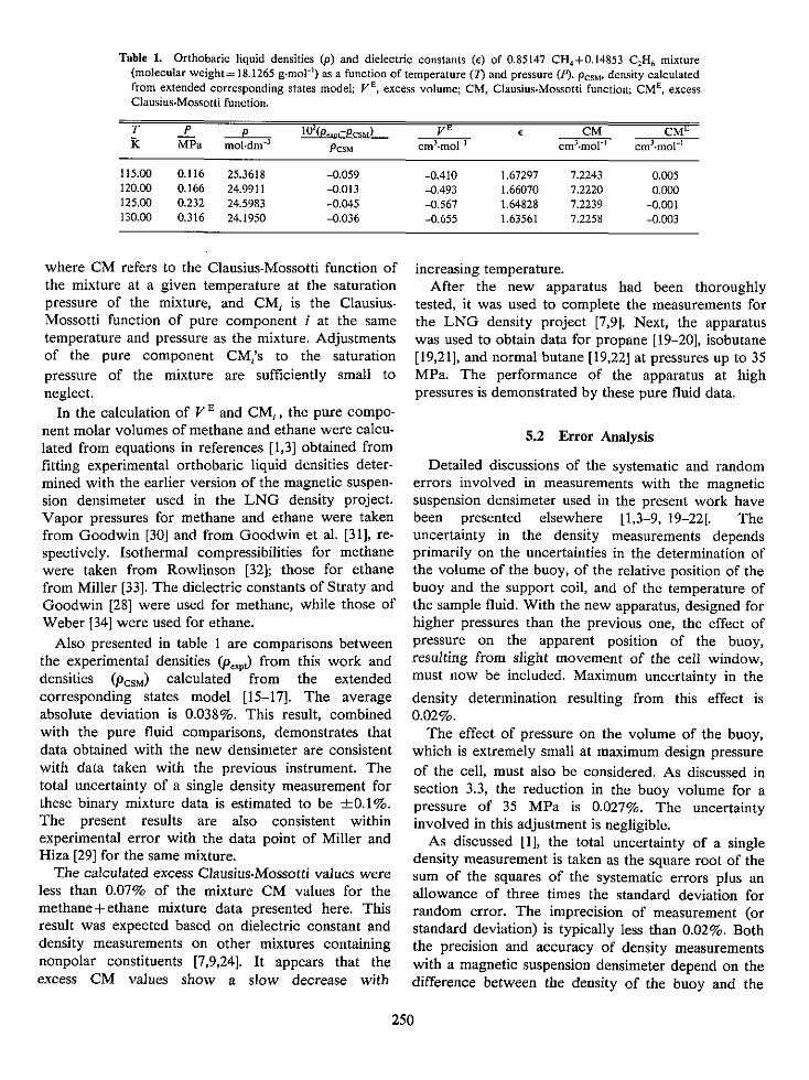
Table 1. Orthobaric liquid densities (p) and dielectric constants (c) of 0.85147 CH 4 +0.14853 C2 H6 mixture(molecular weight= 18.1265 g-mol ') as a function of temperature (7) and pressure (P). Pcsu' density calculatedfrom extended corresponding states model; V2 , excess volume; CM, Clausius-Mossotti function; CME, excessClausius-Mossotti function.
T P p 102
(p_,,l-PCSM) V_ ii CM CMEk MPa mol.dm-' PCSM cmn.molh' cm3 .mol"' cm3 -mol'
115.00 0.116 25.3618 -0.059 -0.410 1.67297 7.2243 0.005120.00 0.166 24.9911 -0.013 -0,493 1.66070 7.2220 0.000125.00 0.232 24.5983 -0.045 -0.567 1.64828 7.2239 -0.001130.00 0.316 24.1950 -0.036 -0.655 1.63561 7.2258 -0.003
where CM refers to the Clausius-Mossotti function ofthe mixture at a given temperature at the saturationpressure of the mixture, and CM, is the Clausius-Mossotti function of pure component i at the sametemperature and pressure as the mixture. Adjustmentsof the pure component CM,'s to the saturationpressure of the mixture are sufficiently small toneglect.
In the calculation of VE and CM1 , the pure compo-nent molar volumes of methane and ethane were calcu-lated from equations in references [1,3] obtained fromfitting experimental orthobaric liquid densities deter-mined with the earlier version of the magnetic suspen-sion densimeter used in the LNG density project.Vapor pressures for methane and ethane were takenfrom Goodwin [30] and from Goodwin et al. [31], re-spectively. Isothermal compressibilities for methanewere taken from Rowlinson [32]; those for ethanefrom Miller [33]. The dielectric constants of Straty andGoodwin [28] were used for methane, while those ofWeber [34] were used for ethane.
Also presented in table I are comparisons betweenthe experimental densities (p,,,j from this work anddensities (pcsM) calculated from the extendedcorresponding states model [15-17]. The averageabsolute deviation is 0.038%. This result, combinedwith the pure fluid comparisons, demonstrates thatdata obtained with the new densimeter are consistentwith data taken with the previous instrument. Thetotal uncertainty of a single density measurement forthese binary mixture data is estimated to be ±0.1%.The present results are also consistent withinexperimental error with the data point of Miller andHiza [29] for the same mixture.
The calculated excess Clausius-Mossotti values wereless than 0.07% of the mixture CM values for themethane+ethane mixture data presented here. Thisresult was expected based on dielectric constant anddensity measurements on other mixtures containingnonpolar constituents [7,9,24]. It appears that theexcess CM values show a slow decrease with
increasing temperature.After the new apparatus had been thoroughly
tested, it was used to complete the measurements forthe LNG density project [7,9]. Next, the apparatuswas used to obtain data for propane [19-20], isobutane[19,21], and normal butane [19,22] at pressures up to 35MPa. The performance of the apparatus at highpressures is demonstrated by these pure fluid data.
5.2 Error Analysis
Detailed discussions of the systematic and randomerrors involved in measurements with the magneticsuspension densimeter used in the present work havebeen presented elsewhere [1,3-9, 19-22]. Theuncertainty in the density measurements dependsprimarily on the uncertainties in the determination ofthe volume of the buoy, of the relative position of thebuoy and the support coil, and of the temperature ofthe sample fluid. With the new apparatus, designed forhigher pressures than the previous one, the effect ofpressure on the apparent position of the buoy,resulting from slight movement of the cell window,must now be included. Maximum uncertainty in the
density determination resulting from this effect is0.02%.
The effect of pressure on the volume of the buoy,which is extremely small at maximum design pressureof the cell, must also be considered. As discussed insection 3.3, the reduction in the buoy volume for apressure of 35 MPa is 0.027%. The uncertaintyinvolved in this adjustment is negligible.
As discussed [1], the total uncertainty of a singledensity measurement is taken as the square root of thesum of the squares of the systematic errors plus anallowance of three times the standard deviation forrandom error. The imprecision of measurement (orstandard deviation) is typically less than 0.02%. Boththe precision and accuracy of density measurementswith a magnetic suspension densimeter depend on thedifference between the density of the buoy and the
250
density of the fluid. For the present arrangement,where the density of the buoy is significantly larger(typically an order of magnitude) than the density ofthe fluids, the precision and total uncertainty change
slowly with fluid density. The total systematic error inthe measurement process from known sources isapproximately 0.05% at low temperatures, decreasingto approximately 0.03% at room temperature. Thisresults in an estimated total uncertainty in the densityof approximately 0.1% at low temperatures and 0.06%
at room temperature. (Of course, the uncertainty in
the density determination also depends on the values
of the derivatives, (ap/aPl) and (ap/a7r), for theparticular region of the PVT surface for the fluidunder investigation.)
The uncertainties in the dielectric constant determi-nation have been discussed in detail (sec. 4.3 and refs.
[7,9,19-22]). The total uncertainty in the dielectricconstant measurement is estimated to be approximate-ly 0.01%.
The estimates of the uncertainties in the density and
dielectric constant measurements can be tested tosome degree by making comparisons with reliable datafrom independent sources. Such comparisons have
been made for many fluids over wide ranges of experi-mental parameters (such as temperature, pressure, den-
sity, etc.) [7,9,19-22]. In general, these comparisonshave confirmed the estimates of the uncertainty levels.
There has been little information presented in thispaper concerning the problems associated withmixture measurements compared to pure fluidmeasurements. The uncertainties involved in thedetermination of the composition of mixtures havebeen discussed in detail in previous papers [1,5-9].
The authors are grateful to the following individualswho made significant contributions in the develop-ment of this apparatus. W. R. Bjorklund, A. N.
DiSalvo, W. G. Layne (deceased), and D. L. Smithassisted in the fabrication of the apparatus. M. J. Hiza
participated in many fruitful discussions. H. M.
Ledbetter provided prepublished bulk modulus datafor barium ferrite.
6. References
[11 Haynes, W. M.; Hiza, M. J.; Frederick, N. V. Magnetic
suspension densimeter for measurements on fluids of
cryogenic interest. Rev. Sci. Instrum. 47(10): 1237-1250;
1976 October.[21 Haynes, W. M. Simplified magnetic suspension densimeter for
absolute density measurements. Rev. Sci. Instrum. 48(1):
39-41; 1977 January.[3] Haynes, W. M.; Hiza, M. J. Measurements of the orthobaric
liquid densities of methane, ethane, propane, isobutane, and
normal butane, J. Chem. Thermodyn. 9(2): 179-187; 1977
February.[4] Haynes, W. M.; Hiza, M. J. Orthobaric liquid densities of
normal butane from 135 to 300 K as determined with a
magnetic suspension densimeter. Advances in Cryogenic
Engineering, Vol. 21. Timmerhaus, K. D.; Weitzel, D. H.,ed, New York, NY: Plenum Press; 1976 516-521.
[51 Hiza, M. J.; Haynes, W. M.; Parrish, W. R. Orthobaric liquiddensities and excess volumes for binary mixtures of low
molar-mass alkanes and nitrogen between 105 and 140 K. J.
Chem. Thermodyn. 9(9): 573-896; 1977 September.[61 Hiza, M. J.; Haynes, W. M. Liquid mixture excess volumes
and total vapor pressures using a magnetic suspensiondensimeter with compositions determined bychromatographic analysis: methane plus ethane. Advances
in Cryogenic Engineering, Vol. 23. Timmerhaus, K. D., ed.
New York, NY: Plenum Press; 1976; 594-601.
[71 Haynes, W. M. Orthobaric liquid densities and dielectric
constants of (methane + isobutane) and (methane + normal
butane) at low temperatures. J. Chem. Thermodyn. to be
published.
18l Hiza, M. J.; Haynes, W. M. Orthobaric liquid densities and
excess volumes for multicomponent mixtures of low molar.mass alkanes and nitrogen between 105 and 125 K. J.
Chem. Thermodyn. 12(t): 1-10; 1980 January.191 Haynes, W. M. Measurements of orthobaric-liquid densities of
multicomponent mixtures of LNG components (N2 , CH4 ,CH 6, CH 8 , CH 3 CH(CH3 )CH,, CH,,, CH 3CH(CH 3 )C2 H,,
and C,H,2 ) between 110 and 130 K. J. Chem. Thermodyn.14(7): 603-612; 1982 July.
[10] Goodwin, R. D. Apparatus for determination of pressure.
density-temperature relations and specific heats of
hydrogen to 350 atmospheres at temperatures above 14 K.
J. Res. Natil, Bur. Stand. (U.S.) 65C(4): 231-243; 1961
October-December.[ill Prydz, R.; Straty, G. C. The thermodynamic properties of
compressed gaseous aid liquid fluorine. Natl. Bur. Stand.
(U.S.) Tech. Note 392; 1970 October; 182 p.
[12] Straty, G. C.; Prydz, R. Fluorine compatible apparatus for
accurate PVT measurements. Rev. Sci. Instrum. 41(8):
1223-1227; 1970 August.[13] Straty, G. C. (p,VT) of compressed fluid ethene. J. Chem.
Thermodyn. 12(8): 709-716; 1980 August.[141 Frederick, N. V.; Haynes, W. M. Differential capacitance
sensor as position detector for a magnetic suspension
densimeter. Rev. Sci. Instrum. 50(9): 1154-1155; 1979
September.[15] McCarty, R. D. A comparison of mathematical models for the
prediction of LNG densities. Natl. Bur. Stand. (U.S.)
NBSIR 77-867; 1977 October. 60 p.
251

116] McCarty, R. D. Four mathematical models for the predictionof LNG densities. Nati. Bur. Stand. (U.S.) Tech. Note1030; 1980 December. 76 p.
[171 McCarty, R. D. Mathematical models for the prediction ofliquefied-natural gas densities. J. Chem. Thermodyn. 14(9):837-854; 1982 September.
1181 Hiza, M. J. An empirical excess volume model for estimatingliquefied natural gas densities. Fluid Phase Equilibria 2(2):27-38; 1978 August.
1191 Haynes, W. M.; Younglove, B. A. Dielectric constants ofsaturated liquid propane, isobutane, and normal butane.Advances in Cryogenic Engineering, Vol. 27. Fast, R. W., ed.New York, NY: Plenum Press; 1982. 883-891.
[201 Haynes, W. M. Measurements of densities and dielectricconstants of liquid propane from 90 to 300 K at pressuresto 35 MPa. J. Chem. Thermodyn. to be published.
[211 Haynes, W. M. Measurements of densities and dielectricconstants of liquid isobutane from 120 to 300 K atpressures to 35 MPa. J. Chem. Eng. Data. to be published.
1221 Haynes, W. M. Measurements of densities and dielectricconstants of liquid normal butane from 140 to 300 K atpressures to 35 MPa. J. Chem. Thermodyn. to bepublished.
[231 Younglove, B. A.; Straty, G. C. A capacitor for accurate widerange dielectric constant measurements on compressedfluids. Rev. Sci. Instrum. 41(7): 1087-1089; 1970 July.
[241 Pan, W. P.; Mady, M. H.; Miller, R. C. Dielectric constantsand Clausius-Mossotti functions for simple liquid mixtures:systems containing nitrogen, argon and light hydrocarbons.AlChE J. 21(2): 283-289; 1975 March.
[251 Clark, A. F.; Haynes, W. M.; Deason, V. A.; Trapani, R. J.Low temperature thermal expansion of barium ferrite.Cryogenics 16(3): 267-270; 1976 May.
[26] Ledbetter, H. M. Fracture and Deformation Division,National Engineering Laboratory, National Bureau ofStandards, Boulder, CO 80303. private communication.
[271 Haynes, W. M.; McCarty, R. D. Prediction of liquefied-natural-gas (LNG) densities from dielectric constantmeasurements. Cryogenics. to be published.
1281 Straty, G. C.; Goodwin, R. D. Dielectric constant andpolarizability of saturated and compressed fluid methane.Cryogenics 13(12): 712-715; 1973 December.
[29] Miller, R. C.; Hiza, M. J. Experimental molar volumes forsome LNG-related saturated liquid mixtures. Fluid PhaseEquilibria 2(l): 49-57; 1978 August.
[301 Goodwin, R. D. The thermophysical properties of methane,from 90 to 500 K at pressures to 700 bar. NatI. Bur. Stand.(U.S.) Tech. Note 653; 1974 April; 274 p.
[31] Goodwin, R. D.; Roder, H. M.; Straty, G. C. Thermophysicalproperties of ethane, from 90 to 600 K at pressures to 700bar. Natl. Bur. Stand. (U.S.) Tech. Note 684; 1976 August.319 p.
[32] Rowlinson, J. S. Liquid and Liquid Mixtures. 2nd Ed. London:Butterworths; 1969. 51.
1331 Miller, R. C. Estimating the densities of natural gas mixtures.Chem. Eng. 81(23): 134-135; 1974 October.
[34] Weber, L. A. Dielectric constant data and the derivedClausius.Mossotti function for compressed gaseous andliquid ethane. J. Chem. Phys. 65(1): 446-449; 1976 July.
252