'App I to Test Rept on Electrical Separation Verification ...
87
APPENDIX I TO THE TEST REPORT ON ELECTRICAL SEPARATION VERIFICATION TES'I'ING FOR THE CAROLINAPOWER AND LIGHT COMPANY FOR USE IN THE SHEARON HARRIS NUCLEAR POWER PLANT For Carolina Power and Light Company Shearon Harris Nuclear Power Plant New Hill, North Carolina 27562 Sb09190299 Bb09ib PDR ADOCK 05000400 A PDR
Transcript of 'App I to Test Rept on Electrical Separation Verification ...

APPENDIX I TO THETEST REPORT ON
ELECTRICALSEPARATIONVERIFICATIONTES'I'ING
FOR THECAROLINAPOWER AND LIGHTCOMPANY
FOR USE INTHESHEARON HARRIS NUCLEAR POWER PLANT
For
Carolina Power and Light CompanyShearon Harris Nuclear Power Plant
New Hill,North Carolina 27562
Sb09190299 Bb09ibPDR ADOCK 05000400A PDR

M4%

Test ReportREPORT NO. 47879-06
WYLE JOB NO.
CUSTOMERP. O. NO.
PAGE 1 OF80
47879-03
PAGE REPORT
DATE Ma 27 1986
SPECIFICATION (S)
See References in Section 5.0.
1.0 CUSTOMER
ADDRESS
2.0 TEST SPECIMEN
Carolina Power and Li ht Com an
Shearon Harris Nuclear Power Plant New Hill NC 27562
Power, Control, and Instrumentation Cables
as described in Paragraph 6.0
3.0 ABSTRACT
The test program described herein was conducted for Carolina Power and Light Company'sShearon Harris Nuclear Power Plant to support compliance with Regulatory Guide 1.75,Revision 1, "Physical Independence of Electrical Systems", and with Section 5.1.1.2 ofIEEE Standard 384-1974, "IEEE Trial-Use Criteria for Separation of Class 1E Equipmentand Circuits", which allows the use of testing and analyses to justify separation of lessthan the spatial requirements of Sections 5.1.3 and 5.1.4 of IEEE Standard 384-1974.
The tests described were conducted to supplement testing reported in Wyle LaboratoriesTest Report No. 47879-02, Revision A. This document serves as Appendix I to thatreport.
'mk)sTATE oF ALABAMA a ama ro essional Eng,coUNTY oF MADlsoN ) *'eg. No. 13475
Gerald R. Carbonneau being d iydeposes and says: The Information contained In this report ls the result of completeand carefully condu ted tests and ls t of his knowledge true and correct In
'"5K a&8UBS ISED and sworn to bef me this dayof, 1
Notary ubllc In and for the State of Alabama at large.
, tg Z2'yCommission expires
APPROVED BY
WYLEQ. A.
nso
G. ayne Hi ht
LABORATORIES SCIENTIFIC SERVICES & SYSTEMS GROUPHUNTSVILLE,ALABAMA
ttrtte Iltas ttee no ssblstr rofdttmaoes et lorefsttn or~. Nckttstte spocisl ter
ottsetatentat damattea'
a byt 'eport.
PREPARED BYne

Page No. 2
Test Report No. 47879-06
4.0 „SUMMARYThe test program described in this document consisted of three individual tests to evaluatephysical independence between rigid steel conduits and between rigid steel conduits and freeair cabling. The results of the test program and the test procedure are contained in thefollowing sections:
~ .~ Section I Test Program and Results
o Section II Wyle Laboratories'est Procedure 47879-05
Each of the three tests were conducted in the following sequence:
Baseline Functional Tests
Overcurrent Test
Post overcurrent Test Functional Tests.
5.0
5.1
5.2
5.3
5.4
5.5
5.6
Nyle Laboratories Test Report No. 47879-02, Revision A, "Test Report onElectrical Separation Verification Testing for the ICarolina Power and LightCompany for use in the Shearon Harris Nuclear Power Plant".
IEEE Std. 383-1974, "IEEE Standard for Type Test of Class 1E Electric Cables,Field Splices, and Connections for Nuclear Power Generating Stations."
IEEE Std. 384-1974, "IEEE Trial Use Standard Criteria for Separation of Class 1EEquipment and Circuits."
United States Vtuclear Regulatory Commission Guide 1.75, Revision 1, "PhysicalIndependence of Electric Systems."
IEEE Std. 323-1974, "IEEE Standard for Qualifying Class 1E Equipment forNuclear Power Generating Stations."
Code of Federal Regulations, Section 10, Part 21.
Code of Federal Regulations, Section 10, Part 50, Appendix B.
WYLE LABORATORIESHuntsville Facility

1 Page No. 3 tTest Report No. 47879-06
TEST SPECIMEN DESCRIPTION
All cables used in this test program were qualified to meet the requirements of IEEEStandard 383-1974, "IEEE Standard for Type Test of Class 1E Electrical Cables, FieldSplices, and Connections for Nuclear Power Generating Stations". The test specimensconsisted of the following cables installed into the various configurations as described inSectionI of this report and were provided to Wyle Laboratories from the Shearon HarrisNuclear Power Plant stock.
Item No. DescriptionCable*yp'OLB/M**
Triplex 350 MCM
1/C 10 AWG
1 Pair 16 AWG(TP 16 AWG)
P —Power Type CableL —Low Energy Type Cable
B/M = Billof Materials Number
P
P
L
D25-10
D25-01
D60-Ql
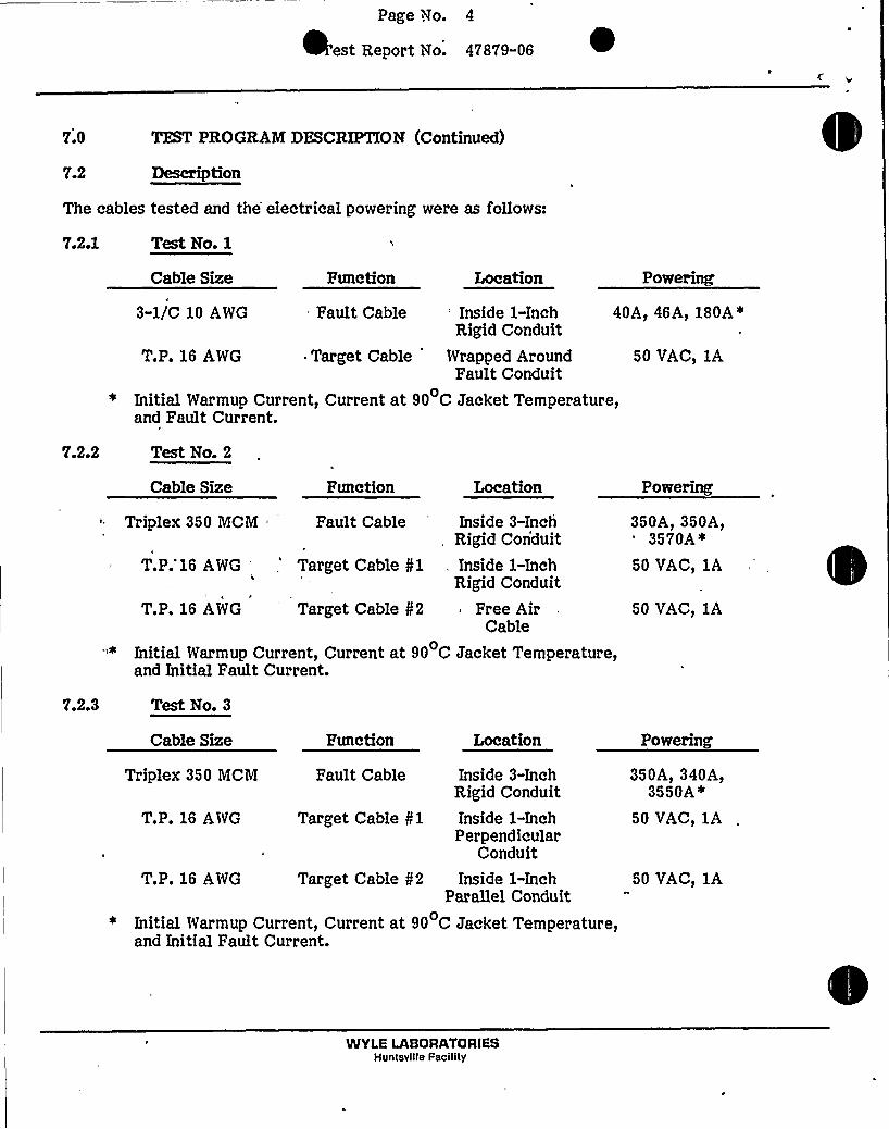
TEST PROGRAM DESCRIPTION7.0
These tests consisted of three individual tests between parallel rigid steel.conduits and/orfree air cables mounted 1/4-inch apart'or in-contact at a point when crossing. For Test 1,the target cable was wrapped around the 1-inch conduit containing the faulted cable. ForTest 2, the target conduit was 1/4-inch above and parallel to the 3-inch fault conduit. Inaddition, a free air cable dropped 1/4-inch horizontally away from the fault conduit. ForTest 3, one target conduit touched the fault conduit, at a point, and the other target conduitran parallel with 1/4-inch horizontal separation.
7.1 Purposes
The purposes of these tests were to:
1. Demonstrate the acceptability of design where a control or instrumen-tation (low energy) conduit is in-contact with a raceway or cable requiringseparation (Test 1).
2..Demonstrate the acceptability of design where a rigid conduit passes 1/4-inch horizontally or vertically away from a rigid conduit containing theworst case power-type cable (Tests 2 and 3).
3. Demonstrate the acceptability of design where a free air cable isphysically separated by 1/4-inch horizontally from a rigid conduitcontaining the worst case power-type cable (Test 2).
4. Demonstrate the acceptability of design where a rigid conduit touches, at apoint, a second rigid conduit containing the worst case power-type cable(Test 3).
WYLE LABORATORIESHuntsville Facility
Page 'go. 4
est Report No. 47879-06
7.0 TEST PROGRAM DESCRIPTION (Continued)
7.2 Description
The cables tested and the electrical powering were as follows:
7.2.1 Test No. 1
Cable Size Function Location Powering
7.2.2
40A, 46A, 180A*
50 VAC, 1A
Test No. 2
3-1/C 10 AWG Fault Cable: Inside 1-InchRigid Conduit
T.P. 16 AWG ~ Target Cable Wrapped AroundFault Conduit
Initial Warmup Current, Current at 90 C Jacket Temperature,and Fault Current.
Cable Size Function Location Powering
Triplex 350 MCM Fault Cable
T.P.'16 AWG,'arget Cable Nl
T.P. 16 AWG Target Cable g2
Inside 3-InchRigid Conduit
Inside 1-InchRigid Conduit
Free AirCable
350A, 350A,3570A4
50 VAC, 1A
50 VAC, IA
7.2.3
Initial Warmup Current, Current at 90 C Jacket Temperature,and Initial Fault Current.
Test No. 3
Cable Size
Triplex 350 MCM
T.P. 16 AWG
Function
Fault Cable
Target Cable g1
Location
Inside 3-InchRigid Conduit
Inside 1-InchPerpendicular
Conduit
Powering
350A, 340A,3550A*
50 VAC, 1A
T.P. 16 AWG Target Cable N2 Inside 1-InchParallel Conduit
Initial Warmup Current, Current at 90 C Jacket Temperature,and Initial Fault Current.
50 VAC, 1A
WYLE LABORATORIESHuntsville Facility

lPage No. '
Test Report No. 47879-06
7.3
TEST PROGRAM DESCRIPTION (Continued)
Results
The results of these tests are briefly summarized in the foQowing tables:
V.3.1 Test No. I
Cable Size
3-1/C 10 AWG
Function Location'aultCable Inside I-Inch
Rigid Conduit
Maximum TemperaturesJacket Conduit
396 F 170 F
T.P. 16 AWG Target Cable WrappedAround Conduit
148 F N/A
Time to Imition:
Time to Open Circuit:
Target Cable Performance:
None
116.63 seconds at 180 amperes
'onducted I A at 50 VAC throughout Overcurrent Test.Passed Post-Overcurrent Test Functional Tests.
~
~ ~V.3.2 Test No. 2
Cable Size
Triplex 350 MCM
Function Location
Fault Cable Inside 3-InchConduit
Maximum TemperaturesJacket Conduit
1339 F 609 F
T.P. 16 AWG Target Cable 01 Inside 1-InchConduit
250 F 283 F
T.P. 16 AWG Target Cable N2 Free AirCable
211 F N/A
Time to Ignition:
Time to Open Circuit:
None
401.77 seconds. Fault current was 3570 amperesinitially, but dropped to 2520 amperes as the cableheated, and then rose to 4200 amperes as short-circuiting occurred prior to open-circuit.
Target Cable Performance: Conducted 1 A at 50 VAC throughout Overcurrent Test.Passed Post-Overcurrent Test Functional Tests.
WYLE LABORATORIESHuntsvilta Facility

Page No. 6
est Report No. 47879-06
V.O
7.3
7.3-3
TEST PROGRAM DESCRIPTION (Continued)
Results (Continued)
Test No. 3
Cable Size
Triplex 350 MCM
T.P. 16 AWG
T.P. 16 AWG
Function Location
Fault Cable Inside 3-InchConduit
Target Cable N1 Inside 1-InchPerpendicular
Conduit
Target Cable N2 Inside 1-InchParallelConduit
Maximum TemperaturesJacket Conduit
1382 F 589 F
187 F 247 F
188 F 257 F
Time to Ignition:
Time to Open Circuit:
None
382e52 seconds. Fault current was 3550 amperesinitially, but dropped to 2600 amperes as the cableheated, and then rose to 4200 amperes as short-circuiting occurred prior to the open-circuit.
Target Cable Performance: 'onducted 1 A at 50 VAC throughout Overcurrent Test.Passed Post-Overcurrent Test Functional Tests.
V.4 Conclusions
The above results generated the following conclusions:
The acceptability of design/construction was demonstrated for the followingphysical separation distances:
1. 0-inch separation (in-contact) between a free air cable and a 1-inch rigidconduit, containing a low energy cable, when the worst case electricalfault occurs in the conduit.
2. 1/4-inch vertical separation between any two parallel rigid conduits whenthe worst case electrical fault occurs in the lower conduit.
3.
4.
1/4-inch horizontal separation between any two parallel rigid conduitswhen the worst case electrical fault occurs.0-inch separation (in-contact) between any two rigid conduits in aperpendicular crossing situation when the worst case electrical faultoccurs.
5. 1/4-inch horizontal separation between a free air cable and a perpendicularrigid conduit when the worst case electrical fault occurs in the conduit.
WYLE LABORATORIESHuntsville Facility

Page Vto. 7
Test Report Vto. 47879-06
8.0 QUAIZTYASSURANCE
All work performed on this test program was done in accordance with WyleLaboratories'uality
Assurance Program, which complies with the applicable requirements of 10 CFR 50,Appendix B; ANSI N45.2, and the "daughter" standards. Defects are reported in accordancewith the requirements of 10 CFR Part 21.
9.0 TEST EQUIPMENT AND INSTRUMENTATION
All instrumentation, measuring, and test equipment used in the performance of this testprogram were calibrated in accordance with Wyle Laboratories'uality Assurance Program,which complies with the requirements of Military Specification MIL-STD-45662. Standardsused in performing all calibrations are traceable to the National Bureau of Standards byreport number and date. When no national standards exist, the standards are traceable. tointernational standards or the basis for calibration is otherwise documented.
WYLE LABORATORIESHuntsville Facility

C-'I
gt

Page No. I-1
Test Report No. 47879-06
:oiSECTION I
TEST PROGRAM AND RESULTS
1.0 TZSI'EQUIREMENTS
Acceptance Criteria
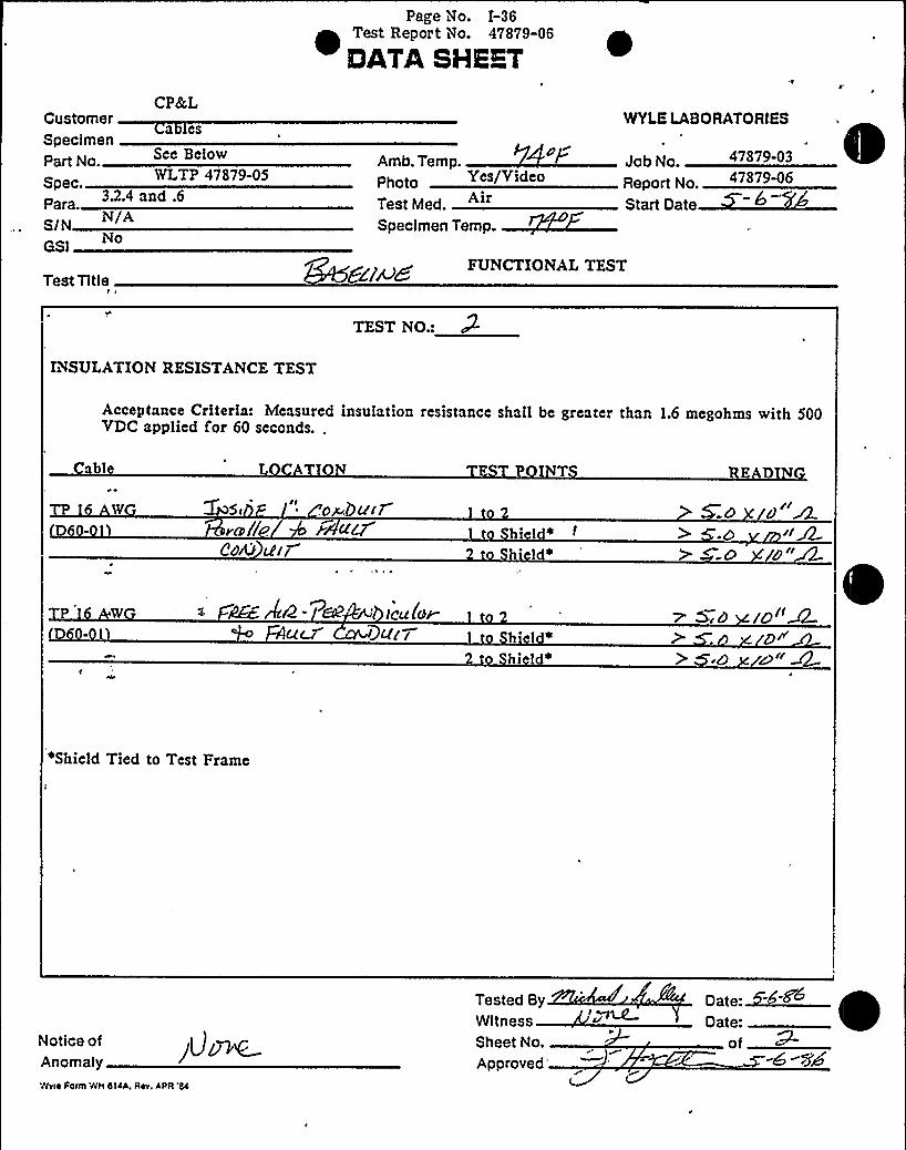
Insulation Resistance Test
Insulation resistance on the "target cables"* shall be greater than 1.6 x 10 ohms with apotential of 500 VDC applied for 60 seconds. Before testing insulation resistance fromphase to conduit (shield), the shield to conduit continuity shall be measured with anohmmeter. AllInsulation Resistance Tests shall be performed as soon as practical after theOvercurrent Test.
1.1.2 High Potential Test
There shall be no evidence of insulation breakdown or Qashover with a potential of1600 VAC applied for one minute.
1.1.3 Cable Continuity Test~
~ ~ ~Energized specimens in the target raceway shall conduct 100% of NEC-ratedtable below) at 50 VAC before, during, and after the overcurrent test.
currents (see
CableSize
No.Conductors
COL - CableLD. No. Type Voltage
RatedCurrent
16 AWG 1 Tw. Pr. D60-01 L 50 VAC 1A
Tolerances
All target cable voltages specified in this procedure shaQ be maintained within a +3%tolerance. AH target cable currents shall be maintained within a+10% tolerance.
Allfault cable currents shall be maintained within a +3% tolerance, ifpossible.
The term "target cable" refers to energized and monitored nonfault cables usedin this program.
WYLE LABORATORIESHuntsville Facility

Page No. I-2
est Report No. 47879-06
2 0 . TEST PROGRAM
2.1 Test Specimen Inspection
An inspection of the test specimen cables and conduits was performed prior to starting thetest program. This inspection verified that the specimens were as stated in Paragraph 6.0 ofthe Summary Section. Applicable manufacturer, part number, cable size, and cable B/Mnumber were recorded on a Test Specimen Inspection Sheet. The test specimens werelabeled with Quality Assurance "Test Specimen" tags to facQitate identification throughoutthe test program.
2.2 Test Specimen Preparation
- The test specimens were mounted into the test assemblies of Figures I-I, I-3, or I-5. Thisapparatus was manufactured to the indicated dimensions by Wyle technicians using materialssupplied by CPdcL. The following guidelines were observed with regard to the materials andconstruction of the test assembly:
1. The faulted cable was a 3-1/C 10 AWG cable for Test 1, and a Triplex350 MCM cable for Tests 2 and 3. This cable was mounted inside a 1-inchconduit for Test 1, or a 3-inch conduit for Tests 2 and 3.
2.
3y
The ends of the faulted cable were wrapped from their termination on thecopper bus bar to the edge of the test assembly. This wrap consisted of asingle layer of HAVEG SILTEMP WT-65 or 188 CH covered with a singlelayer of 3M No. 69 glass tape.. This wrapping was done as a safety measure'o ensure that any ignition that occurred was contained to the test area.
The target cable(s) was a Twisted Pair (T.P.) 16 AWG cable for all threetests. This cable(s) was mounted as described below:
Test See Target- No. ~ Pigure-No. Cable No.
1 1
Location
Free Air Cable looped around fault conduit twice
Inside 1-inch conduit 1/4-inch above fault cable
Free Air Cable dropping 1/4-inch perpendicularlyfrom fault conduit
Inside 1-inch conduit crossing the fault conduit
Inside 1-inch conduit 1/4-inch horizontallyfrom fault conduit
4. The target cable conduits were cut 24 inches shorter than the fault cableconduit and the target cable was wrapped, as necessary, after it exited theconduit. This was done to ensure that the target cable was not damagedfrom flames outside the fault cable conduit.
WYLE LABORATORIESHuntsville Faclllty

Page No. I-3
Test Report No. 47879-06
'.2 TEST PROGRAM (Continued)
Test Specimen Preparation (Continued)
2.3
2.3.1
5. Photographs were taken of the test setup prior to each test.
6. A I/2-.inch VHS recording was taken of the Overcurrent Test.
Instrumentation Setup
Thermocouple Locations
A total of 22 (Test 1), 30 (Test 2), or 35 (Test 3), Type "K" thermocouples were utilized forthese tests. The thermocouples were mounted as described below:
ChannelNo.
TestNo. Location
1-8
9'011-18
1»3
1-3
1-3
Mounted to the jacket on the fault cable. Thesethermocouples were mounted approximately 12inches apart.
"Mounted to the conductor of the fault cables at thetwo series connections.
Mounted'to the jacket of the target cable. ForTest 1, these thermocouples were between theconduit and the target cable. For Tests 2 and 3,these therm ocouples were on the cable in theconduit parallel with the fault conduit.
19-21
22-26
27-29
1-3
2 2 3
. Mounted to the. outside of the..fault cable conduit.These thermocouples were spaced 24 inches apart.
Mounted to the jacket of the target cable perpen-dicular to the fault conduit. One thermocouple wasat the crossing point and 2 thermocouples mountedat 2 inches and 6 inches from the crossing point.
Mounted to the outside of the parallel target cableconduit. These thermocouples were mounted evenwith Channels 19-21.
30-34
22 (Test 1) 1-330 (Test 2)
or 35 (Test 3)
Mounted to the outside of the perpendicular targetcable conduit. One thermocouple was mounted onthe side at the crossing point and 2 thermocouplesmounted at 2 inches and 6 inches from the crossingpoint.
Ambient temperature probe.
WYLE LABORATORIESHuntsville Facility

Page No. I-4
est Report No. 47879-06
2.0 TEST PROGRAM (Continued)
2.3 Instrumentation Setup (Continued)
2.3 J. Thermocouple Locations (Continued)
The thermocouples were monitored by a Fluke Datalogger feeding a high-speed printer. Thedatalogger was operated at its maximum rate throughout the Overcurrent Test.
2.3.2 Electrical Monitoring
Channel No. Test No.
3
1-3
1-3
2'1-3
1-3.
Signal
Current
Voltage
Current
Skipped
Current .-
Cable
T.P. 16 AWG Target Cable Nl
T.P. 16 AWG Target Cable (Common)
T.P. 16 AWG Target Cable N2
N/AFault Cable
I
A digital multimeter was utilized to measure the voltages and currents of the target cablesprior to, during, and after the fault current portion of the Overcurrent Test. This data wasrecorded to provide accurate evidence of the specimen's capability to conduct rated currentat 50 VAC throughout the Overcurrent Test.
The voltages and currents of the target cables and the fault cable current were fed into anoscillograph recorder. The oscillograph was operated at the 0.1-inch per minute ratethroughout the Overcurrent Test. The oscBlograph channels were as specified in thefollowing table.
2.4 Baseline Functional Tests
The baseline functional tests consisted of insulation resistance and high potentialmeasurements on the target cables. These tests were performed as described below.
2.4.1 Insulation Resistance Test
1. The power and instrumentation leads were disconnected from the targetcables.
2. Shield-to-conduit resistance was measured with a multimeter and recorded.
WYLE LABORATORIESHuntsville Facility

Page No. I-5 tTest Report No. 47879-06
2.4
2.4.1
TEST PROGRAM (Continued)
BaseIine Functional Tests (Continued)
Insulation Resistance Test (Continued)
3. Using a megohmmeter, a potential of 500 VDC was applied and theminimum insulation resistance indicated after a period of 60 seconds wasrecorded between the following test points:
Target Instrument Cable:
Phase-to-Phase Phase-to-Ground
1to2 1 to shield~2 to shield*
Shield tied to conduit or unistrut frame.
2.4.2
For all performances of this test, the measured values were compared to,the acceptancecriteria, Paragraph 1.1.1, i.e., greater than 1.6 x 10 ohms.
High Potential Test, '
1. Using a Hi-Pot 'Test.Set, 'a potential 'of 1600 VAC was applied and theleakage current observed after a .period of 60 seconds was recordedbetween the following test points:
Target Instrument Cable:- 4
Phase-to-Phase Phase-to-Ground
1to2 1 to shield*2 to shield*
Shield tied to conduit or unistrut frame.
2. Allpower and instrumentation leads were reconnected.
For all performances of this test, the measured values were compared to the acceptancecriteria, Paragraph 1.1.2, i.e., there shall be no evidence of insulation breakdown orflasho ver.
WYLE LABORATORIESHuntsville Facility

Page No. I-6
est Report No. 47879-06
2.0 'EST PROGRAM (Continued)
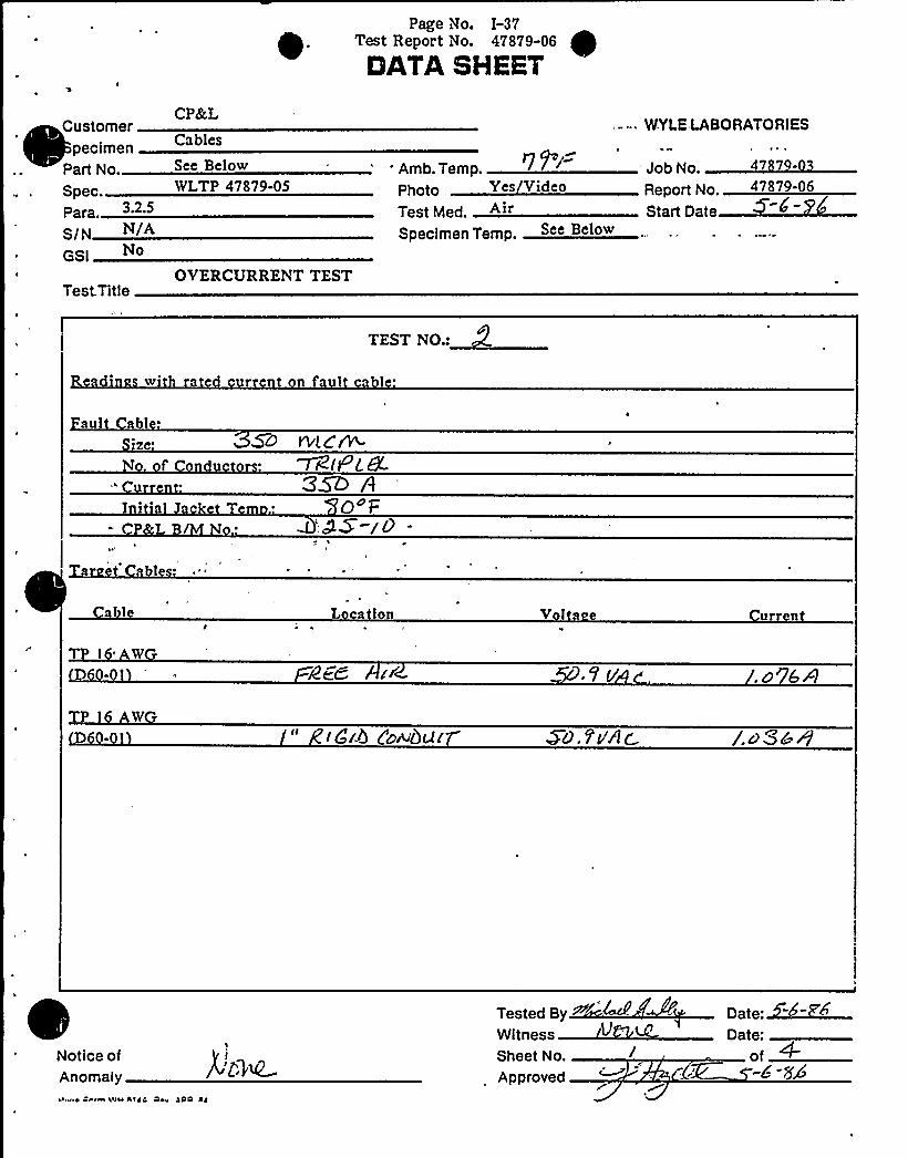
2.5 Overcurrent Test
The Overcurrent Test was conducted in two'sequential steps with no intentional time delay.The first phase consisted of powering the fault cable with rated current and increasing thiscurrent until temperatures of 90 C +5 C were indicated for 15 minutes on the fault cable.The second phase consisted of energszing the fault cable with the test current until thecable open-circuited.
The target cables conducted rated current at 50 VAC throughout the Overcurrent Test. TheOvercurrent Test was conducted using the followingprocedure:
The 3-1/C 10 AWG (Test 1) or Triplex 350 MCM (Tests 2 and 3) fault cablewas connected to the copper bus bars per Figures 4 of Section II.
2.
3.
T.P. 16 AWG target cables were installed per Figures I-l, I-.3 or I-5, asapplicable.
The T.P. 16 AWG target cables were connected to the instrumentation andpower supplies of Figure 5 of Section IL
4. The T.P. 16 AWG target cables were energized with 1 ampere at 50 VAC.
„5.
6.
The 3-1/C 10 AWG, (Test 1) or Triplex 350 MCM (Tests 2 and 3) fault cablewas energized with 40amperes (Test 1) or 350 amperes (Tests 2 and 3)(rated current) from the Multi-AmpTest Set.
Target cable voltages and currents and.the. fault cables current wererecorded.
8.
Fault cable gurreqt was increased until thermocouple Channels 1-10indicated a 90 C +5 C conductor temperature.
The temperature was maintained at 90 C +5 C for 15 minutes.
9. Fault cable current and conductor temperature were recorded.
10. The Multi-Amp Test Set output was increased to 180 amperes (Test 1) orits.maximum output current (Tests 2 and 3) (test current).
11. Target cable voltages, currents and the fault cable current were recorded.
12. The fault cable was allowed to conduct test current until the cable open-circuited.
WYLE LASORATORIESHuntsville Factllty

Page No. I-7
Test Rep'ort No. 47879-06
2.5
TEST PROGRAM (Continued)
Overcurrent Test (Continued)
13. Time to open-circuit and maximum fault cable temperature were recorded.
14.. Target cable voltages and currents were recorded.
15. The target cables and the Multi-AmpTest Set were de-energized.
16. The post-test conditions were photographed.
For all performances of this test, the observed target cable operation were compared to theacceptance criteria, Paragraph 1.1.3, i.e., they shall maintain continuity of power.
2.5 Post-Overcurrent Test Functional Test
The functional tests of Paragraph 2.4 were repeated on the target cables as soon as possibleafter the Overcurrent Test. 'tt
WYLE LABORATORIESHuntsville Faclllty

Page No. I-8
est Report No. 47879-06
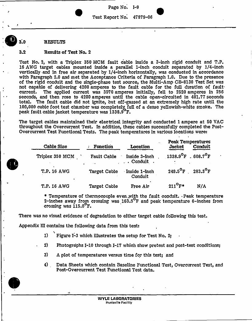
3.0 RESULTS
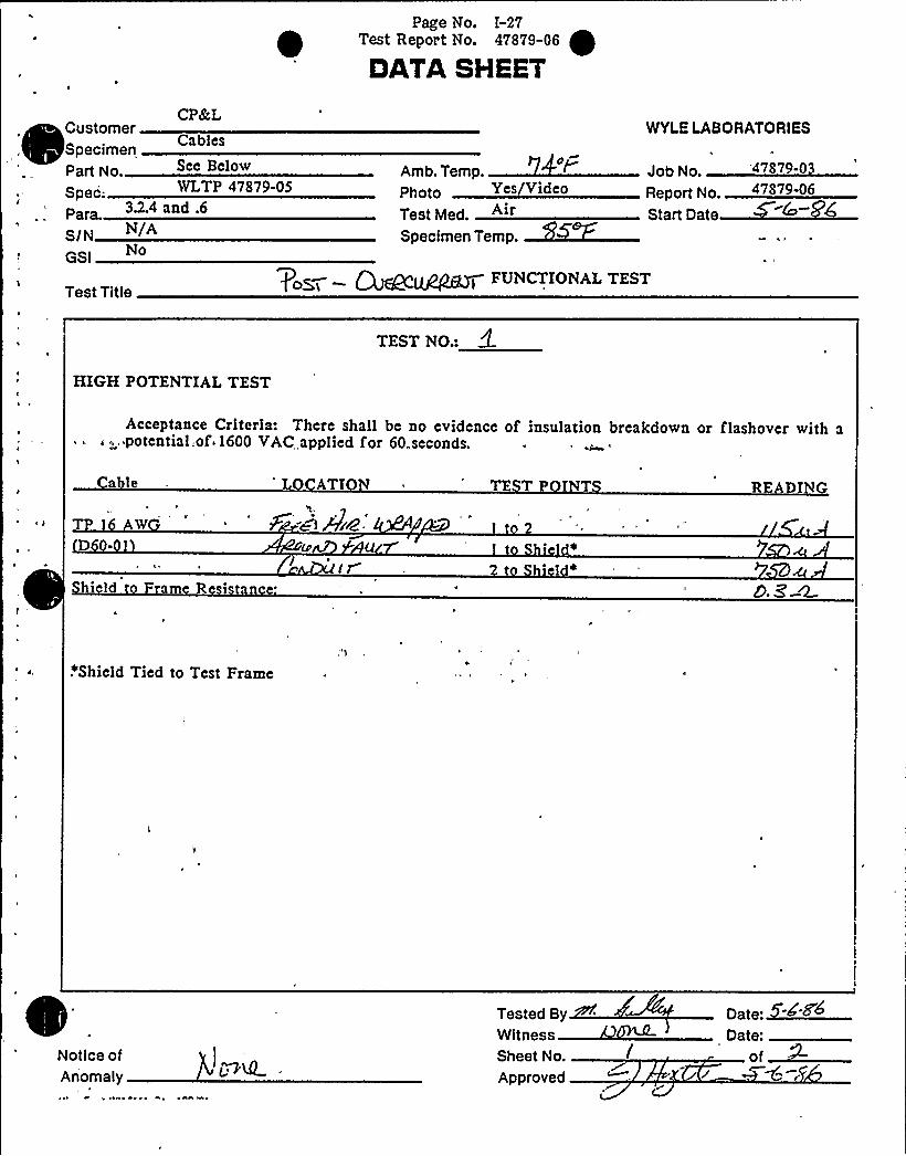
3.1 Results of Test No. 1
Test No. 1, with a 3-1/C 10 AWG fault cable inside a 1-inch rigid conduit and a T.P. 16 AWGtarget cable wrapped around the conduit, was conducted in accordance with Paragraph 2.0and met the Acceptance Criteria of Paragraph 1.0. The 180ampere fault current wasapplied untQ the cable open-circuited in 116.63 seconds. The fault cable did not ignite andopen-circuited before heavy off-gassing could occur. The peak fault cable jackettemperature was 396.2 F.
The target cable maintained its electrical integrity and conducted 1ampere at 50 VACthroughout the Overcurrent Test. In addition, the cable successfully completed the Post-Overcurrent Test Functional Tests. The peak temperatures recorded were:
Cable Size
3-1/C 10 AWG
Function
Pault Cable
Location
InsideConduit
Peak Temperature
396.2 P
N/A
T.P. 16. AWG
1-Inch Conduit N/A
Target Cable WrappedAround Conduit
169.7 P
147.7 P
There was no visual evidence of degradation to the target cable following this test.
Appendix I contains the following data applicable'to the entire test program:
1) Test Specimen Inspection Sheet'which lists materials from CPRL stockused during the test program;
2) . -Photographs I-1 and I-2 which show the test setup; and
3) Instrumentation Equipment Sheet which lists equipment used to take datafor all phases of testing.
Apendix II contains the following data applicable to Test No. 1:
1) Figure I-1 which Blustrates the setup for Test No. 1;
2) Photographs I-3 through I-9 which show pretest and post-test conditions;
3) A plot of temperature versus time; and
4) Data Sheets which document Baseline Functional Test, Overcurrent Test,and Post-Overcurrent Test Functional Test data.
WYLE LABORATORIESHuntsville Faclllty
Page No. I-9 ~Test Report No. 47879-06
.;d3e2
RESULTS
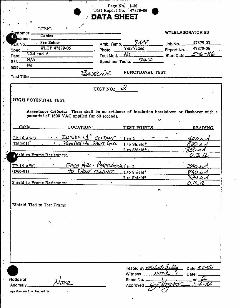
Results of Test No. 2
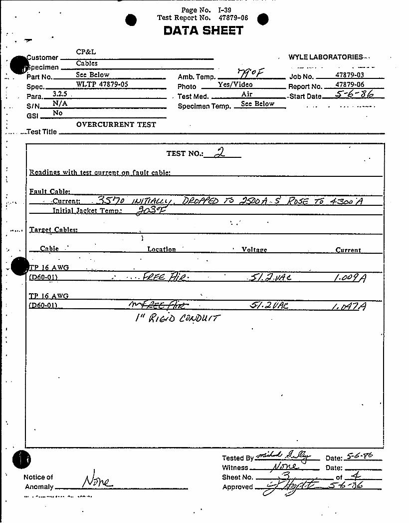
Test No. 2, with a Triplex 350 MCM fault cable inside a 3-inch rigid conduit and T.P.16 AWG target cables mounted inside a parallel 1-inch conduit separated by 1/4-inchvertically and in free air separated by 1/4-inch horizontally, was conducted in accordancewith Paragraph 2.0 and met the Acceptance Criteria of Paragraph 1.0. -Due to the presenceof the rigid conduit and the single-phase test source, the Multi-Amp CB-8130 Test Set wasnot capable of delivering 4200 amperes to the fault cable for the fuH duration of fault.current. The applied current was 3570 amperes initially, fell to 2520 amperes in 256seconds, and then rose to 4200 amperes until the cable open-circuited in 401.77secondstotal. The fault cable did not ignite, but off-gassed at an extremely high rate until the100,000 cubic foot test chamber was completelg full of a dense yellowish-white smoke. Thepeak fault cable jacket temperature was 1338.9 F.
The target cables maintained their electrical integrity and conducted 1 ampere at 50 VACthroughout the Overcurrent Test. In addition, these cables successfully completed the Post-Overcurrent Test Functional Tests. The peak temperatures in various locations were:
Cable Size Functio'n Location
Triplex 350 MCM 'ault Cable Inside 3-Inch.. Conduit
Peak TemperaturesJacket Conduit
, 1338.9 F 608.7 F
T.P. 16 AWG
T.P. 16 AWG
249.5 F 283.3 FTarget Cable Inside 1-InchConduit
Target Cable Free Air 211 F* N/A
* Temperature of thermocouple even„with the fault conduit. Peak temperature2-inches away from crossing was 163.5 F and peak temperature 6-inches fromcrossing was 115.0 F.
There was no visual evidence of degradation to either target cable following this test.
Appendix IIIcontains the following data from this test:
1) Figure I-3 which illustrates the setup for Test No. 2;
2) Photographs I-10 through I-17 which show pretest and post-test conditions;
3) A plot of temperatures versus time for this test; and
4) Data Sheets which contain Baseline Functional Test, Overcurrent Test, andPost-Overcurrent Test Functional Test data.
WYLE LABORATORIESHuntsville Facility

age o.
'eet Report No. 47878-06
3.0 RESULTS
3.3 Results of Test No. 3
Test No. 3, with a Triplex 350 MCM fault cable inside a 3-inch rigid conduit and T.P.16 AWG target cables mounted inside a parallel 1-inch conduit separated by 1/4-inchvertically and inside a perpendicular 1-inch conduit separated by 0-inches (in-contact at apoint), was conducted in accordance with Paragraph 2.0 and met the Acceptance Criteria ofParagraph 1.0. Due to the presence of the rigid conduit and the single-phase test source,the Multi-Amp CB-8130 Test Set was not capable of delivering 4200 amperes to the faultcable for the fuQ duration of fault current. The applied current was 3550 amperes initially,fell to 2600 amperes in 232 seconds, and then rose to 4200 amperes until the cable open-circuited in 382.52 seconds total. The fault cable did not ignite, but off-gassed at anextremely high rate untB the 100,000 cubic foot test chamber was completelg fullof a denseyellowish-white smoke. The peak fault cable jacket temperature was 1381.9 F.
The target cables maintained their electrical integrity and conducted 1 ampere at 50 VACthroughout the Overcurrent Test. In addition, these cables successfuQy completed the Post-Overcurrent Test Functional Tests. The peak temperatures in various locations were:
Cable Size
Triplex 350 MCM
T.P. 16 AWG
Function -, Location
Fault Cable Inside 3-InchConduit
Target Cable 'nside Parallel1-Inch Conduit
Peak TemperaturesJaoitet Conduit
0 01381.9 F 588.9 F
188.1 F 256.7 F
'arget Cable Inside 187.0 F* 246.5 F**Perpendicular.1-Inch Conduit
~ Temperature of jacket thermocouple at the crossing point with the faultconduit. Peak temperature 2-inches away from crossing point was 180.2 F andpeak temperature 6-inches from crossing point was 142.9 F.
Temperature of conduit at the crossing point wit) the fault conduit. Peaktemperature 2-inches from crossing point was 205.5 F and peak temperature6-inches from crossing point was 130.7 F.
T.P. 16 AWG
1) Figure I-5 which iQustrates the setup for Test No. 3;
2) Photographs I-18 through I-24 which show pretest and post-test conditions;
3) A plot of temperatures versus time for this test; and
There was no.visual evidence of degradation to either target cable following this test.
Appendix IV contains the following data from this test:
4) Data Sheets which contain Baseline Functional Test, Overcurrent Test, andPost-Overcurrent Test Functional Test data.
WYLE LABORATORIESHuntsville Faclllty

Page No. I-11
Test Report No. 47879-06
APPENDIX I
TEST SETUP DATA .
Test Specimen Inspection Sheet '
Photographs,Instrumentation Equipment Sheet
WYLE LABORATORIESHuntsville Facility

Page No. I-12Test Repor t No. 47879-06
TEST SPEClMEN 1NSPECTlON
CHECK AS APPROPRIATE
ITEMNO. DESCRIPTION
g6'k ~ VVlCfA~ 0 u'8c. C~b K
MANUF.
dier 7i=.
.- -- CUSTOMER
JOB NO. 4'787 I -0 9SPECIFICATION tA ~~8 8'7 9 -0DATE lAi ) (
PARTIMODEL NO
nO
O~
lrl a'0
IP
0 +So
iO )4~2ov vAc. Sf'.
4f7d
—.D~O U iTrgi
NOTES: cc ~ ~ 7~i 'AP (F-8~
Specimen Failed e
Specimen Passed
NOA Written
Inspected B
WitnessSheet No.
Approved
ot
Date: <- ~ -><Date:

Page No. 1-13
Test Report No. 47879-06
SIA'I"+ $ Q "~ A ' rt
~ o~+
g'4 Qv,
~ k
~ rr
"Pgjf
1
2 '- '*".:*'
.'II
A Cg
wJb
ttrfffP ~l
I
'vs
pp-+g~p. W
PHOTOGRAPH NO. I-1I*
VIEW OF ELECTRICALSUPPLIES USED TOPOWER AND'MONITOR'ARGEl'ABLES
~ 1 I
)AS
g
. "'~A'PS
Sr ~'
S'I
fPg~5, 0
I 'g l
S
p gCgP.,%.pg Q~
p(
S
Ifr'
5 ~>P4(R
Il- )mXraa'I~ill 'I ~
51~ S ~ "~ Il ',1'rl. ~ 1-rr
~ ~ .~ ~ f ~ I~ I ~ j' ~ '
I ~, ~ . I ~ j ~(PItf
: ~
g" g
-'Sf'HOTOGRAPH
NO. I-2
VIEW OF INSI'RUMENTATIONSETUP SHOWING FLUKEDATALOGGER, HONEYWELLOSCILLOGRAPHS, AND
TEXAS INSTRUMENTS HIGH&PEED PRINTER

Fage No. I-14Test Report No. 47879-06
INSTRINENTATION EQUIPNENT SHEET PABE 1 OF 1
DATE 05/05/86 . JOB NO. 4787M3 LOCATION ACOUSTIC
TECHNICIAN VICTOR ROHAO CUSTONER CP 4 L TYPE TEST CABLE SEP.
HO. INSTRINENT NANUFACTURER NDELS SERIAL 0 WYLH RAHSE 1 ACCURACY 1 CALDTE CAUSE
1 DIBITAL TENP
2 CALIBR VOLT
3 %6 NTE TSTR
4 DI6 NTR
5 DIB NTR
6 PRINTERS
7 DATALOS6ER
8 OSCILLDBRAPH
9 AKPL BALVO
10 NTR CURRENT
11 XFORNER
12 XFOINER
13-DIB NTR
14 TENP IND
15 HETER CURRENT
16 lKB NTE. TSTR
FLUKE 2190A
FLUKE Y2003
GEH RADIO 18620
KEITHLEY 130A
KEITHLEY 130
'EXAS INSTWT 810
FLViK 2240C
HONEYIIELL 1508
HONEYIIELL T66AS
FLUKE N/A
BROMNELL 5SFT
BR%NELL . 5SFT
H/P 3476B'NESA115KF
IJLTI RIIP CB8130
ASSOC RESEARCH 4030A
8$N/A
2374
193257
N/A
0471194217
2970007
452
1618
N/A
H/A
k/A7439
000085
31208R:
510
094906 Nm.T
094907 10-IOONV
097892 .5-2000KH
100863 DC
003105 DC
011777 PN
102363 QTI. SDEB
096056 . 1"80IH/SEC
094505 DC TO 5 KHI
092675 (HiN ANP
100665 100/SANP
102783 100/5 ANP
011203 DC
101881 "SH8NO+F K
100413 60KQIPS
100165 4KV
Me 03%
+-. (N~3'.SENDMe 255
M.SII)FB. 02IIRD
Bk.IN BITL
ISF
+-3'-f0'5$
+-SgI.SS2IIX
04/07/86
04/07/8604/28/8612/11/8502/05/8603/21/86ii/14/8501/16/8612/23/85ii/11/8504/30/8604/30/8602/20/8602/25/8602/17/8605/05/86
07/07/86
07/07/8610/28/8606/11/8602/OS/87
09/21/86OS/14/8607/16/8606/23/8605/11/8610/30/8610/30/8605/20/8608/25/8602/17/8811/05/86,'"
THIS IS TO CERTIFY THAT THE ABOVE INSTRUNENTS HERE CALIBRATED USI% STATEM-THEWRT TECHHIQUES, HITH STANDARDS
IIHOSE CALIBRATION IS TRACEABLE TO THE NATIONAL BUREAU OF STANDARDS.
INSTRUNENTATION CHECKED 4 RECEIVED BY

Page No. 1-15
Test Report No. 47879-06
APPENDIX II
TEST NO. I DATA
Pigure. Photographs,
PlotData Sheets
WYLE LABORATORIESHuntsville Facility

rage No. I-16Test Report No. 47879-06
FAULT CABLE
, UNZSTRUT FRAME
1" OD CONDUZT
T P ~ 16 AWG
TARGET CABLE(LOOP AROUND CON-DUZT TWO TZMES)
3-1/C 10 AWG FAULT CABLEZN 1" CONDUZT
T PE 16 A$%.TARGET CABLE
1P2 12 Pl ~
30"-
FRONT VIEW TOP VZEW
HGURE I-is TEST NO. i SETUP

t Page No. I-17
Test Report No. 47879-06
~ Qa a'o
"44a
o(ao'
at,
a
~o m +'I0 l1 '08~.cf!Laoa nV.Q~~~ 448C,,~ ALi
aaa
~aQao.,~ o
PHOTOGRAPH NO. I-3
TEST NO. 1 PRETEST VIEW SHOWING TARGET CABLEWRAPPED AROUND FAULTCONDUIT
,aR,ay Q
4at,,
~ttv'a
'rC 'z
,ao ~ oot ~1&+" C»aaooo ~ C, a . *
Mft~aol, aooa., +AC~~ aa ~
taS&lgOL ~ ag
PHOTOGRAPH NO. I-4
PRETEST VIEW SHOWING ONE TERMINATIONOF THE 3-1/C 10 AWG FAULTCABLE

Page No. I-18
Test Report No. 47879-06
}'p
$
~ '>}«
>Y
}I,>, >«
Y YVj
r'«I
'J"
I
i>««
VVVI«V
>«
««,«; «> j
. PHOTOGRAPH NO. I-5I
POST-TEST OVERALLVIEW
t
«@yJ>+>~v,, Util 'g '
'}«lo
«Y>«~ vv> }}v>>Y«4 «, 'v', '41 «va
'<~~ «}
gj«i>Y- vc
w'>«>'>'> «>4~ ~ C «>!L
>!« t«« Yv>«~ m g ««}Y~ fwALJ ~r
PHOTOGRAPH NO. I-6
POST-TEST SIDE VIEW OF TARGET CABLEAND FAULTCABLE
Page No. I-19
Test Report No. 47879-06
~ » »g
i
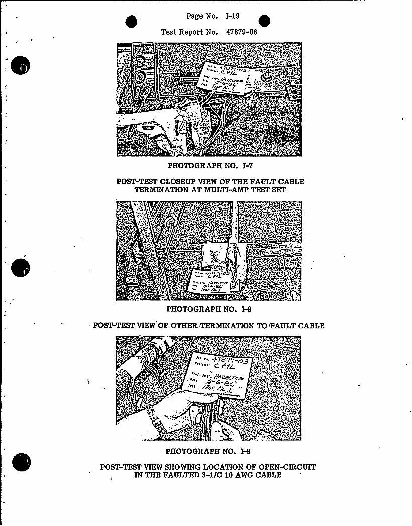
PHOTOGRAPH NO. I-7
POST-TEST CLOSEUP VIEW OF THE FAULTCABLETERMINATIONAT MULTI-AMPTEST SET
PHOTOGRAPH NO. I-8
POST-TEST VIEW OF OTHER.TERMINATIONTO'FAULTCABLE
~re+ S
ph
PHOTOGRAPH NO. I-9
POST-TEST VIEW SHOWING LOCATION OF OPEN-CIRCUITIN THE FAULTED3-1/C 10 AWG CABLE

1 jtj y c rr 4
1500
1400
1300
1200
1100
1000
900
((00
700
650
D 600
550
500
450
400
350
300
FIGURE I-2: TEST NO. I
:»jii:il
i»„i
1
t
.i.1
t»»!
:i
i
-'1:i-1»i ~
» I 1
gaff)!
1!1:
»i.
'i!.
til!f!»
lilt
'Jth'1
.i!;
!'.!!
F:,
'I1
I
'j i
'ljlj»
»!
„':»! lil: .Ii:.: ':fjif!!.:qqLL
!i' hi i(:i :ii:!1»
!',ji
it»'li(i
!L!i
:ii
»»tgt:! i!::ii
ji''ti !1!i 'I illl !If i,i
i i:jrl''L:!J
i j'0i » .1V
ii:1!j!i! i. 1'.
it!i'i!'i!
,1
1'1
i:ljh
iji;,jrFi:.i:h
Fl::
't! ;I(
;Vj,i!
. i!!1 1
'. i.i"(j
,ii;jlii
IjL»
I it j
;:Ij
:i(i'iitJ I!
:!V
!!1 1
;thii;i»1'4
Tti
!!h': lli!4
i!VV'
i(!(tt
(!(i
ilil
ii»!l.
jril:1»
f!0
ifi:
::hii!f
!Vl
i!h
!(V
iii!it j!i.
!4 ~
.»i»i'(!(i,
0(:ii!:glt hi,
j'ih 'j'f
i)i(L'i,
!hi:r;
iiiI»
;i!
sr!
;1!!
:i'V
'iil
»1
'1»4:1
1 1 »ill!
", jl'''!h(ti!! fjii t ij
hiilJlf:
'h:jlti'i.'ii
!i:i
1»;i»
I.EGEND:
0 FAUI.TCARI.E JACKET TEhIPERATURE (T/Cs 1-8)
~ FAULTCaBLE CONDUIT TEhIPERATURE (T/Cs IV-20)
6 TARGET CARI,E JACKET TEhIPERATURE (T/Cs II-I6)ambient Temp: 72 P
Date: 05/06/86
V»
1:j;
ii'.,
ii,'l
lL'ii!
jtji.gj
iJf ii.
ilh
i:,f»i!i
j!i'!V
!i
LL
ti
j:i
'I',
i,,'i;i
ljf!
I!ii
jtr'.
1,
(if,'ilj
hij
li»,'!:i:l:
i'i,
Tri'i!I
:1!.
fj;iiI
)Ij
»!i:!1,
ih
(j»
('i!:;! 1
! ili.
!:"it
l,
i:ti
!1
!(l
rrrh
rjt!i I 1
V.t
: jr.
».i
ij;r
frV
1»t!I tt'i:i
'I»
;Ill,'Ij1 I
ji
:,i',
ii
1»
t!h
:-'Iht
tii,!i jr
!Ti!
(ii
I:!i'.',illj
»I
»
i itLi!i
".1!
41
ih
li(ii'
1;
ijjjigi
i'f.
h
ji!
fj
ilf
jI!f1
I
!h
iiijil;!ijl
L!li
fl
Fj
ii..! (.
i(ff
fj:
!i
, i!1!
1141
!"I
rh
:i
:jt,I
I
I:it
I
!i
ii'h
illj
ljilt
i:
fg
LI
ll
i,jl;1:! i!1!!
ljttgl!.i.
i»t
j»''»i:1
.4I", i.
r !i»'1 tii!ji 'iii
'ft'Vi
'i
Ir
'(
itj
!!I I
1!ji
jhi
i'ljti',i j::
il!I
:»t»
Lll 1
i 1!: jV,h 'ji
.(i! ht: r
jj!V!:ifi
:!(ilh'. »
t!»1
i'!i!it',
i»16(
jt»ltl
'!h
iii!
i»;L'!Li;it»!
!(ri'4lf
:!II1;»ii:..i
!i6
I('!6L'lb
h: J»irl 1ill 1 L
'."I
Tji
,"iit!1 J.t"
1" vriiljf iillji ll6!i j
1 'lii9:.i,V
i»i
!i».!1ii;':1'»
I!:,
i"':ir»:
j"i.hi
i 1 V
i!ii
!V!!i
1!t!!r»!
Vtt1(r
1:iij1»i
'L!:1:
-,r:
:i»
1',
.i:I;i;.! 11
ii»I:::
lj»
ii:hrii,'i.
ill!i}ri,'i!
:1::
:ii
i!!
(V;
I !i.i"ih
'i»
1;"
iih
i»!
: 1 1!
..;tV.l
:.1:i!
i:i,'1»
f. t
»1
ji
»;i6 1 'l
i»hl:'i;:
'!;»'::i
:t":1,'I
!1'i:i
i»I'0!
!i:i
!Lfi.j»
!!I
14i;1
!t:!"II
i»i.'!hir:Iii»
!!!j
i'lit
j it I
! 4'ih
444o et
D j.~ aojotj ~gjgt
Cg
250
100
1! I
ti4» 1
ih
I .':
::i.''!
hI;!.
!.l':11
»1i'
Vl.'i;I' l.
:1!!
!!!1
:ijr
'I'0
i!I'i!:.!i'!
iii',
1 iJ
1 1»i''1 I I
:jiiti!
:!!jlj.!l.i!
JL'tj
:!4
!Ii!Fl iii
i »iri
j»lj'!6
'I
i'}L'.il
(!~ili»
i.'i:
i!ii
!I i
(i.qjj':
i.:jVI
ilh
I!(j 2
',ii:;!16ir
i!'i!i i»
lilVI
li
h
»i(i! llI.
Ji
Fi
'. !Li
if
Lj
j»iil
»I»I ii
!i,!1
;'ljt
1 jLl
'li
tt..»t:
»j!ii1';i
;1)!
!j;i»! 1
ihi1!1
j
':I!":ji:
!!Jt,
!:I'":,ji
',1'i;
:l(i
:.:i1;»:l
'l!,
1
I ''hi j(0 ',iji ,'i4it!,!ii',!V
!j!j
fs

Page No. 1-21Test Report No. 47879-06
DATASHEET
CP&LCustomer
Cablespecimen
See Below
Spec J WLTP 47879 05
para 3.2.4 and .6
SfN N~A
3* GSI
Amb. Temp.Photo Yes/Video
Test Med. AirSpecimen Temp,
WYLELABORATORIES
Report No 47879-06
Start Date
I
Test Titlecd) ~ FUNCTIONALTEST
TEST NO.:
HIGH POTENTIAL TEST
Acceptance Criteria: There shall be no evidence of insulation breakdown or flashover with a„..potential of 1600 VAC.applied for 60 seconds. i+
abie
T W
D -0
L ATI
Tree. '4-cg N~i 8)
)e(v
TE P I T
hi
RE Dl
Jdd~A
h Fr ei n'e
~Shield Tied to Test Frame
Notice ofAnomaly /v~~%
Tested By
Sheet No.
Approved
Date:~4~Date:ot~
pre

Page No. I-22Test Report No. - 47879-06~ OATA SHaFT
CP&LCustomer
ablesSpecimen
See BelowWLTP 47879-05
S/N /-GSI
Amb. Temp.Photo Yes/Video
Test Med. AirSpecimen Temp.
WYI.E LABORATORIES
Job No. '7879-03eport No 47879-06
Start Date
Test TitleFUNCTIONALTEST
TEST NO.:
INSULATIONRESISTANCE TEST
Acceptance Criteria: Measured insulation resistance shall be greater than 1.6 megohms with 500. VDC applied for 60 seconds.
a le
.'AWD60- I
LO ATI N
C LuW
Rom Q(s
TETP I T RE DI G
gI/~p +.0 g,/g" l2P o"~
r\
~Shield Tied to Test Frame
Notice ofAnomalyrvra Form 'Lvv 5rcA. Aev ADA '54
Tested ByWitnessSheet No.
J ~
'pproved
Date: -<-<Date:
of

Page No. I-23Test Report No. 47879-06
DATASHEET
Customerpecimengl
Part No.
SpecPara.
SIN N/A~ GSi
Test Title
CP&L
Cables
See BelowWLTP 47879-05
OVERCURRENT TEST
Amb. Temp.Photo Yes Video
Test Med. AirSpecimen Temp. See Below
Job No.
Report No.
Start Date
47
47879-06
, WYLE.LABORATORIES
TEST NO.:
W ur f'a
aul a I
're
~ ~
IG AcQGd r 0- /C.
bl
a le ca u V it e urren
TP l W cM WO. m Ilium I-aZ
TP W
D
Notice ofAnomaly
c oisin aeaa o~ aoo aa
Tested ByWitnessSheet No. /Approved
a
Date:~ ~Date:af~

Page iVo. 1-24Test Report No. 47879-06
DATASHEET
CustomerSpecimenpart No.
Spec.para - 3 2@5
$ /N N/A
GSI
Test Title
CP&L
ables
See BelowWLTP 47879-05
OVERCURRENT TEST
Amb. Temp.photo Yes/Video
Test Med. AirSpecimen Temp.
1
WYLELABORATORIES
Job No. 47879-03
Report No.
Start Date
TEST NO.:~ul c le
aul e'
e I ~
V I u ut
W osw 8
TPI . W
D
Notice ofAnomaly
>s Cartel Vlv41('sv 400 '%C
Tested ByWitnessSheet No.
Approved
Date:Date:of~5 «$ «g

Page No. I-25Test Repor t No. 478?9-06
GAYASHEET
CP8cLCustomer
CablespecimenPart No. See Below
Spec WLTP 47879 05
Para.
$ /N N/A~ -. GSI
OVERCURRENT TEST... Test Title
Amb. Temp.Photo Yes Video
Test Med AirSpecifnen Tefnp See Below
Job No.
Report No.Start Date
47879-0347879-06
WYLELABORATORIES
TEST NO.:~a w
ul a le'e
m
Tar et abi s
Ca e L ati V e urren
I W
6-
DI W
' Notice of NAnomaly
Tested ByWitnessSheet No.
Approved
Date:~<- ~~
Date: ~of

Page No. I-26Test Report No. 47879-06.
DATASHEET
CP&LCustomerSpecimen Cables
part No See Below
Spec WLTP 47879 05
Para.-SIN N~A
GSlOVERCURRENT TEST
Test Title
0Amb. Temp.Photo Ye Vi e
Test Med.Specimen Temp See Below
WYLfLABORATORlfS
Job No
Start Date
TEST NO.:~
au le
'me ir i', 6 ~c..
h rt''ar
e 'leabl
v
a l nvl Via urrent
P W
D.096 4
W
<~ O W'~~Ok.~ ~~~~ u~ A'a~ 4 Au C'4~ CI O lKI+jt56LII QDCK'Ac@ Af7POKA1nO ~/'
~c&W ~ M~ 4. ol cl p
Notice ofAnomaly
IvI %VH VIilk Qsv DQA '1l
Tested ByWitnessSheet No.
Approved
Date: <-<-<~Date:of~
m-4 -si
Page Vio. I-27Test Report No. 47879-06
DATASHEET
CP&LCustomer
CablesSpecimen
See BelowWLTP 47879-05
para 3.2.4 and .6
SIN N~A
GSI
0Amb. Temp.Photo Yes Video
Test Med. A'rSpecimen Temp.
Job No.
Report No.
Start Date
47879-047879-06
WYLELABORATORIES
Test Title oQg FUNCTIONALTEST
TEST NO.:
HIGH POTENTIAL TEST
Acceptance Criteria: There shall be no evidence of insulation breakdown or flashover with a~ ', potential, of.1600 VAC,applied for 60.seconds.
D
a Ie
ha
w F 48r4.
i id Fam R i
T P INT
iel «
hi 1
RE DI G
«Shield Tied to Test Frame
Notice ofAnomaly
Tested By
Sheet No.
Approved
Date: ~<.8'<Date:
of

lPage No. I-28Test Report No. 47879-06
DATASHEET
CP&LCustomer
ablesSpecimenpap No Sec Below
WLTP 47879-05
SIN N/A
GSINo
6Amb. Tempphoto Yes/Video
Test Med. AirSpecimen Temp.
WYLELABORATORIES ~
Job No. 47879-03
eport No 47879-06„~r-M
Test TitleFUNCTIONALTESTbSi—
TEST NO.:~INSULATIONRESISTANCE TEST
Acceptance Criteria: Measured insulation resistance shall be greater than 1.6 megohms with 500VDC applied for 60 seconds.
able L ATI E T I T RE DIN
cP. 4 x./0
~Shield Tied to Test Frame
Notice ofAnomaly
svr ~ Form Wrr 5l4A. rrev, ArrR '5L
Tested ByWitnessSheet No.
Approved
Date: <.<<~Date:
of.. -6-Sb

Page No. I-29
Test Report No. 47879-06
APPENDIX IH
TEST NO. 2 DATA
EigurePhotographs - - .
Plot-Data Sheets
WYLE LABORATORIESHuntsvllte Facility
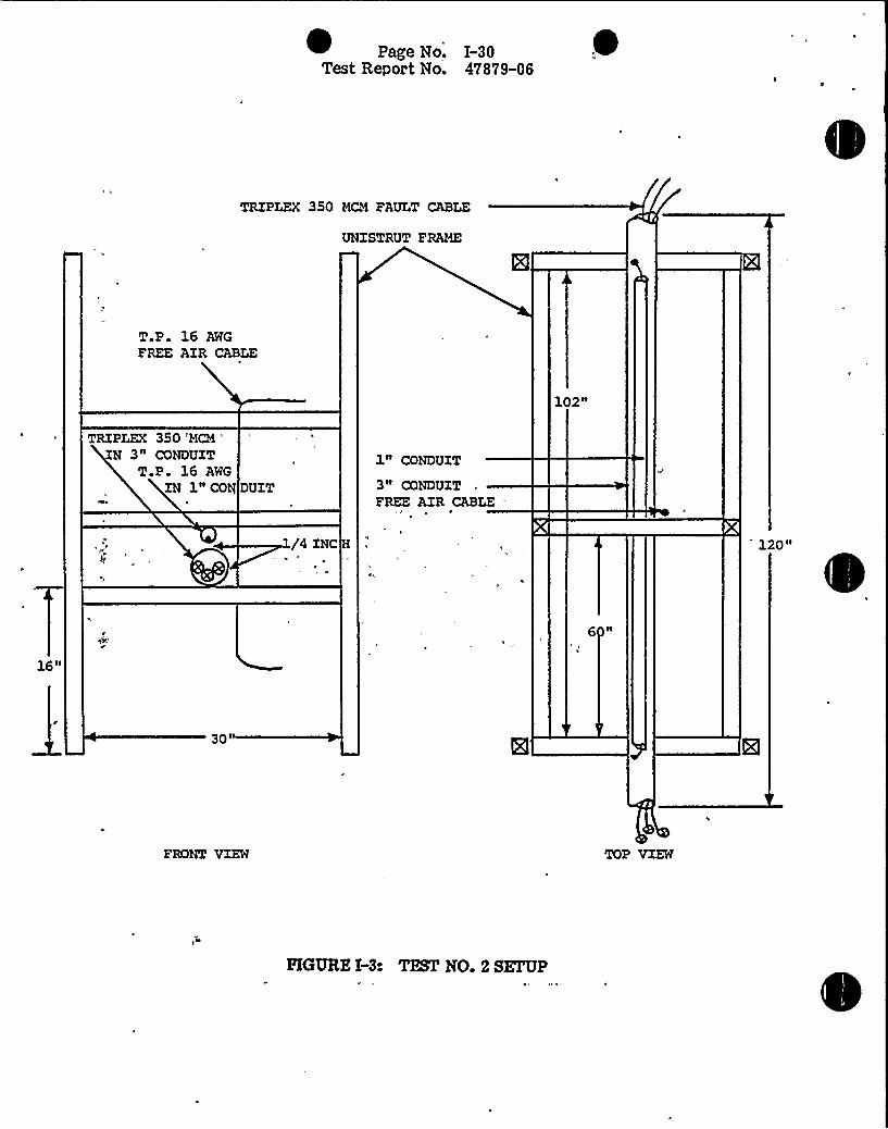
~ Page Ne. 1-30Test Report No. 47879-06
TRIPLEX 350 MCM FAULT CABLE
UNISTRUT FRAME
T P 16 AWG
FREE AZR CABLE
10 2N
TRIPLEX 350 'MCM '
3" CONDUITT P 16 AWG
IN 1N CON DUZT
1" CONDUIT
3" CONDUITFREE AZR CABLE
/4 INC
16N
30'RONT
VIEW TOP VIEW
HGURE I-3: TEST NO. 2 SEFUP

Page No. I-31
Test Report No. 47879-06
P)
~»wj
j4g~g
5jggjay/pf, g
.F
uJ'
g C$ 'f4
j~lg~p',.'HOTOGRAPH
NO. 1-10
TEST NO. 2 PRETEST OVERALLVIEW
PHOTOGRAPH NO. I-11
PRETEST CLOSEUP VIEW OP 3-INCH PAULT CONDUIT,1-INCH PARALLELTARGET CONDUIT, ANDPERPENDICULAR PREE AIRTARGET CABLE
PHOTOGRAPH NO. I-12
PRETEST END VIEW SHOWING WRAPPING ON TRIPLEX 350 MCMPAULT CABLE AND T.P. 16 AWG TARGET CABLE
Page No. I-32
Test Report No. 47879-06
h',
,vl'ihhtIJ«vg8j'baht ~-C
'Cs~
I
I r I/ ~ I
jl I
s.P'S„CI l
pQpg
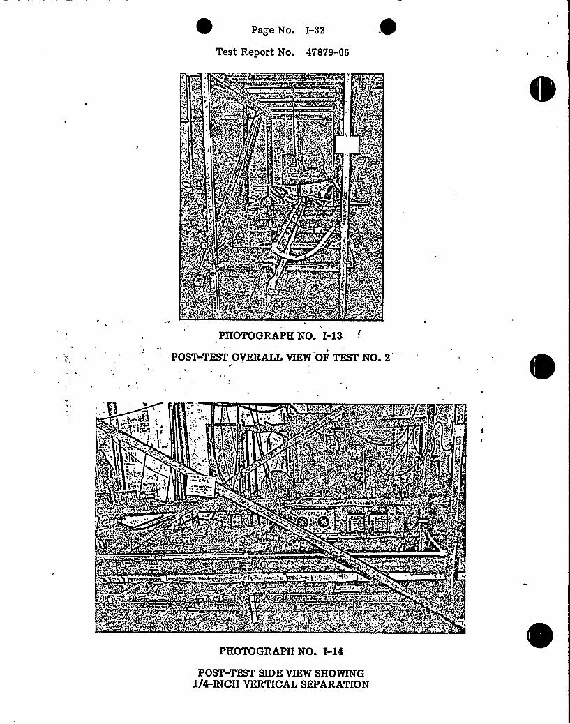
PHOTOGRAPH NO. I-13
POST-TEST OVERALLVIEW OF TEST NO. 2r
I r'fP
~ hl v l'gC
(„j
V ~ 'I~hSIt'P
v psrgb
'
~
PIP Mjtf~~>,v
PI «'I
phvh +A«A$ $ , It tvr
~ig.ltd~'~'u Q."A~.t,"tsl++„ II lh." tv
PHOTOGRAPH NO. I-14
POST-TEST SIDE VIEW SHOWING1/4-INCH VERTICALSEPARATION

Page No. I-33
Test Report No. 47879-06
g4'
a
'I
PHOTOGRAPH NO. I-15
POST-TEST END VIEW SHOWING DARKENINGOF WRAP ON FAULTCABLE
~~ ~
j%
"~
PHOTOGRAPH NO. I-16
POST-TEST VIEW OF BLACKDUST DEPOSIT THATFORMEDAS FAULTCABLE OFFWASSED DURING THE TEST
, i„N~
PHOTOGRAPH NO. I-17
POST-TEST CLOSEUP VIEW OF CROSSING POINT BETWEENFAULTCONDUIT AND T.P. 16 AWG FREE AIR CABLE

(} e "4 cthe,'s Cf
FIGURE IHs TEST NO. 2
1500
1400
1300
1200
1100
1000 . i:
900
.:.':.'EGEND:
0 FAULTCABLEJACKET TEhlPBRATURE (T/Cs 1-8)
~ FAULTCABLE CONDUITTEhlPERATURE (T/Cs 19 21)
0 TARGET CABLE 81 JACKET TEhlPERATURE (T/Cs 11-18)
< TARGET CABLE 82 JACKET TEMPERATURE (T/Cs 22-26)
8 TARGET CONDUITTEhlPERATURE (T/Cs 27-30)
Ambient Temp: 79 PDate( 05/06/86
ht»Il
h
t»I
:i i
I I'Ihif:
j',I jl! » !(:lb
:i~ : i!'iiii:Vi,,'iiiir
» I I
jt!ii;hhlitj
»
'»I
IV i
h i
h
!ht
»
I
)
ll
'i»
IilII»
»
!i!iihi
»
»»» h
I I }I
»,I
»
:»'. I
I I.»:
»fI»II»I
iHI
»
I»I
!jft f(ijl::6 iilj}H}
i!
IHI
I»I
.'i!i»Ill(l
if
»'
I
iii!Ii.'!
i.h
I!!
.»III
I
»!
»Ii
jit:iii
'! II!I
H
I'hi
i»i
»! I
,:jj
ii;»,!
I'oo::i:!:
»I
700 !!'.-"
650 .::::-:
"»I
'i(
Hl'»I»
!I I
illj
il»l I
!itl I ii
»I
»
f !if
»» ii»
lij » I I
I,Ih
h
h
I»
»
»
»
ihl
h
I!s! jiltji!I »iil! I
600
550
500
}eW
450
5 400t350
300
I,.
i»»i:»I
:I'I
.»
'»i
i hi
:iii !ii:i ij',I
.".II .'I.:'. I'-i»!I "::
!»!
ii: Yi'l'!Ij!I .j!I
I'I
j»I !Ill
!! IV! '.Hl
j j I I
»il
li»I!I6:I» I
11!.
j!I,'I
It}I
V»!ih
}Hi il'ii jl
IVI
0
»
hiii
i ii
j h
j!Ji
! IH',»!f
I»
i'rI'
!»I
}I
Hi
»
iiil(H}! I
I',
il
i
I
tlh
Iih.I
i'i}
hi
;i}�'r
»
hi!
II!
» I'I''I rl
:»II .", I I
!I!
ii,jr,}I 'hi
I}hi f
hj
»
h
»I
V
I V
Ih! » h,
»
II
Vll
I!.
»
:Ii'.HVI I »
I'.
»I
Hi i(}i»:j hlI!i!!i}:
I,»
j I II» 44O 0
I
h ore'p
250(I
200
ii'i!'
I.
!H
100
50
--'I!j(»I
150 ii':- :i»
»»I»!
»
3 ( I
rr
I .t»,»j
:i» ig.'!I»» "'j»i:i;ii!!ii Hi:
it}i»
I
Qiij1
,hl
6iH
(!I
»I
»!
Hi ~
',Vi,"jii
lhi ih,,'iij I »
„Hjf
llh
»}iI
'h
'ti I
I li
j
I, . I
'll
ji
jlh
»
;i
» i
f»
»»
I »I!
»
»
ilhir
i
f»
Ij
itihj
»
I»
I
»I
Page No. I-35Test Report No. 47879-06
i DATASHEET
"CP8hLstomer
a eselm en. 'ec Below
WLTP 47879-05
par~ 3.2.4 and .6
SI NN/A
GSl.
O~Amb. Temp.photo Yes/Video
~ gf
Test Med. A'rSpecimen Temp.
VfYLELABORATORIES
Job No 47879-03
Report No. 47879-06
Start Date
Test TitleFUNCTIONALTEST
TEST NO.:
: HIGH POTENTIAL TEST
Acceptance Criteria: There shall be no evidcncc of insulation breakdown or flashovcr with apotential of 1600 VAC applied for 60 seconds.
D
3e
3 W
R
XQ5(De. <4 - ~usa f '+Qv
'3 e ~
DI
0.3,~P W 472 - / &DsOc
2 3e
~Shield Tied to Test Frame
Notice ofAnomalyWyl~ FOyry1 WH 81@A. ReV. APyl 'l4
Tested ByWitnessSheet No.
ApprovedC
Oate: ~<- <~
Oate:af~-8'-88
Page No. I-36Test Report Vio. 47879-06
DATASHEET
CP8hLCustomer
a csSpecimenp ~ N
See BelowWLTP 47879-05
Spec.3.2.4 and .6Para.N/A
GSI
Amb. Temp.photo Ycs/Video
Test Med.Specimen Temp.
NYLELABORATORlES
Job No.
Report No. 47879-06
Start Date
Test TitleFUNCTIONALTEST
TEST NO.:
INSULATIONRESISTANCE TEST
Acceptance Criteria: Measured insulation resistance shall bc greater than 1.6 mcgohms with 500VDC applied for 60 seconds.,
DIN
W Sr,o~arT~e//. F a'a
C'orth'irh'
.d d-c
0 ~c o"
D - 1
~ sf'/2- 68 'ou(&-u~ ~34' h'
h
~ a,o zo"~P0 .0
~Shield Tied to Test Frame
gUrTrmNotice ofAnomalyVlvi~ Farm WH 614A. Aw. AFR 'tg
Tested ByWitnessSheet No.Approved'are:~<~Date:
ofw-6 -88
Page No. I-37Test Report No. 47879-06
DATASHEET
CP&LCustomer
pecimen Cables
part No Scc Below
S'pec WLTP 47879 05
Para.
$ /N N/AGsi
OVERCURRENT TESTTest. Title
nO~ ~'mb. Temp.photo Ycs Video
Test Med. AirSpecimen Temp. See Below
Job No.
Report No.
Start Date
77-47879-06
- -. WYLELABORATORIES
TEST NO.:
f I I
'aul
blzc'
r
SZ n I.C~d r '/t L
0 F':4$ -)0-
a le L a ion V I e urr n
VU .o 64
DW
/4r.h Co~L/ue /.a3bg
Notice ofAnomaly PL'1M
Tested By ~ ~~USheet No.
Approved
Date:~4- ~Date:
of ~-d -89

Page Vio. I-38Test Report Vio. 47879-06
DATASHEET
CustomerSpecimenPart No.
Spec.Para.
N/AGSI
Test Title
CP&L
ables
See BelowWLTP 47879-05
OVERCURRENT TEST
Ama. Tamp.Photo Yes/Video
Test Med. AirSpecimen Temp
Job No
Report No.Start Date
aa
47879-0347879-06
WYLELABORATORIES
TEST NO.:~m ur f u l.
aul abl '
~P
a lea
abl V a
p w0.~Y c ool z)
P
D6-
aaaa
o D.B Vdt"
Notice ofAnomaly
Tested ByWitnessSheet No.
Approved
Oata: ~~>Date:
-4 -3'
Page No. I-39Test Report No. 47879-06
DATASHEET
CP&LCustomer
Cablespecimenpa~ No See Below
Spec WLTP 47879 05
Para.SINGSI
OVERCURRENT TEST..Test Title
Amb. Temp.0
photo Yes/Video
Test Med. AirSpecimen Temp.
Job No.
Report No.
Start Date
47879-0347879-06
WYLE LABORATORIES-
TEST NO.:
d wi h ur a le
aul leurre AJ / Nc A7
e Te 0
D .S 8 7o
l4 184 ~ Tar et a les'
I catl n V lt urren
p wD6- .Od
P W
D - I
/I/ g/~3 gB~klzWi'2d'8e 7g
Notice ofAnomaly
Tested ByWitnessSheet No.
Approved
Date: <~~Date:of~

Page No. I-40Test Report No. 47879-06
DATA SHEET
CP&LCustomer
pecimen Cables
part No Sce Below
Spec WLTP 47879 05
Para.SIN N/AGSi
OVERCURRENT TEST. TestTitle.
o/Amb. Temp.PhotoTest Med. A
Specimen Temp See Below
Job No.
Report No.Start Date
477-
WYLELABORATORlES
TEST NO.: .Xf ul
aul abl:
1 C
T m
n c'i'.e
T CC C
h ir urrcn '
t l ~
a le c tin Vita e urr n
P AWD V e. / a9Zw
DAW
IC l'0 .OMQri l /~BE
Notice ofAnomaly
Tested By ~~~.WitnessSheet No.
Approved
cDate: "Date

Page Vio. 1-41Test Report No. 47879-06
DATASHEET
CP&Lstomer
a escimenNo
+ "See BelowWLTP 47879-05
para 3.2.4 and .6KSI N
N/A
GSI
PouTest Title
WYLELABORATORIES
D~Amb. Temp.Photo Yes/Video
Test Med.
Specimen Temp.
Job No.
Report No.
Start Date
47879-0347879-06
//~g/J~>~f FUNCTIONALTEST
TEST NO.:
HIGH POTENTIAL TEST
Acceptance Criteria: There shall be no evidence of insulation breakdown or flashover with apotential of 1600 VAC applied for 60 seconds.
able READT
p 'ivD WHEE 'iN
P iV
I ( ~Q More
~Shield Tied to Test Frame
Notice ofAnomaly'Nyr~ Form WH d1 jA, Rw. APR '54
Tested ByWitnessSheet No.Approved
Date:Date:
of

Page No. I-42Test Report Vio. 47879-06
DATASHEET
CP8cLCustomer
a esSpecimen
See BelowVLTP 47879-05
Spec3.2.4 and .6Para.
S INN/A
GSI
Amb. Temp.Yes/Video
Test Med.Specimen Temp.
Job No.
Report No.Start Date
OccJ
47879-0347879-06
... WYLELABORAT.ORIES
Test TitleQr~CLtgggt q
FUNCTIONALTEST
TEST NO.:
INSULATIONRESISTANCE TEST
Acceptance Criteria: Measured insulation resistance shall be greater than 1.6 megohms with 500VDC applied for 60 seconds.
K T I R DIN
P W
g,o.0 o'"
0 AC l/8'/-
oS D/d'.
2 xo'~
J'0'Shield
Tied to Test Frame
Notice ofAnomaly'Ittte Fotttt tNH 61AA. Rw. APR '34
Tested ByWitnessSheet No.
Approved
Date: <-~ ~+Date:~of

g ~
Page No. I-43
Test Report No. 47879-06
~ ~
APPENDIX IV
~-r
~ ~ , TEST NO. 3 DATA
Pigure> ~i Photographs ""
PlotData Sheets
WYLE LABORATORIESHuntsvilla Facility

Page No. I-44Test Report No. 47879-06
0
TRIPLEX 350 M~ FAULT CABLE
UNZSTRUT FRAME
3" CONDUIT WITH TRIPLEX350 MCM FAULT CABLE
1" CONDUIT WITH T.P.16 AWG TARGET
CABLESl
1" CONDUIT
3" CONDUIT
10 2 II
1/4 INCH
CROSSING CONDUITMOUNTED ZN-CONTACTAT CROSSING POINT "
60"
30 II
TOP VIEW
HGURE I-5: TEST NO. 3 SETUP
Page No. I-45
Test Report No. 47879-06
p
Pj
, + fiej,Q,Jc.
~2~@)
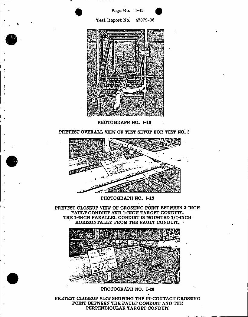
PHOTOGRAPH NO. I-18
PRETEST OVERALLVIEW OP TEST SETUP POR TEST NO. 3
~ ~
e
a
0>L. JP
~tPHOTOGRAPH NO. I-19
PRETEST CLOSEUP VIEW OP CROSSING POINT BETWEEN 3-INCHFAULTCONDUIT AND 1-INCH TARGET CONDUIT.
THE I-INCH PARALLELCONDUIT IS MOUNTED 1/4-INCHHORIZONTALLYFROM THE PAULT CONDUIT.
PHOTOGRAPH NO. I-20
PRETZSI'LOSEUP VIEW SHOWING THE IN-CONTACTCROSSINGPOINT BETWEEN THE PAULT CONDUIT AND THE
PERPENDICULAR TARGET CONDUIT

Page No. I-46
Test Report No. 47879-06
pl~ pp +~)Q~ ~p'N5.k
~ ijtt ~ ~«erat't'47
j
''agtfJ
~ PHOTOGRAPH NO. I-21
POST-TEST OVERALLVIEW SHOWINGTHE,END OP THE PAULT CABLE
CggW '
g~ 'W P~ ~ g< + m.p~$ et
$v
~ 1 1 f
~4
PHOTOGRAPH NO. I-22
POST-TEST CLOSEUP VIEW SHOWING THECROSSING POINT BETWEEN CONDUITS

Page No. I-47
Test Report No. 47879-06
PHOTOGRAPH NO. I-23
POST-TEST CLOSEUP VIEW OF THE TARGET CABLE REMOVEDFROM THE INWONTACTPERPENDICULAR CONDUIT.
NO VISUALDAMAGEWAS NOTED.
PHOTOGRAPH NO. I-24
POST-TEST CLOSEUP VIEW OF THE TARGET CABLEREMOVEDFROEX THE PARALLELCONDUIT SEPARATED BY 1/4-INCH.
NO VISUALDAMAGEWAS NOTED.

0
h
ji!
'i!I
fi
!If.
!II!
!I''
1500
1400
1300
1200
1100
1000
900
500
700
650
600
tf- 550W
500(jj(e
450
4001
350
300o
250a
200
150
100
50
FIGURE 1-6: TEST NO. 3
LEGEND:
0 PAUIT CABI.E JACKET TEhlPERATURE (T/Cs 1-8)~ FAUIT CABLE CONDUITTEhlPERATURE (T/Cs 19-21)0 PARALLELCONDUITTEMPERATURE (T/Cs 27-29)X PERPENDICULAR CONDUITTEhlPERATURE (T/Cs 30-34)V PARALLEI CONDUITTARGET CABI E
TEMPERATURE (T/Cs 11-18)
0 PERPENDICULAR CONDUITTARGET CABLETEhlPERATURE (T/Cs 22-26)
Ambient Temp: 81 PDate: 06/07/86
I::I;,:!!1!!!jf9jh
Ii
!I44ft« .I}! !!II }If:,
r: 4III.'lj,ijj:'f j
!I! !Ii. «I.:4! 4jl:!I!
!H HI! alii(H
f 4}jl114IHI'i
«j!4:I
;;4'.., ",I'
14
II!
4;
IH
'
41'14«
i !! :I,!'. }i}!jjH :14}jr'.I I'I4
9:I:. I,
:!if
!II,h h
'I
H«
«I
0
ti
H
lfI« I4!h
4: lfLqfjf
j«IHh
I in
4If
«II i
:I
'f!i
jf'I 'rjj'
!I!f f:!} IjffjHI!I 't
!I:j;!t,I«:
I!IIj«!'I
II,IIQH!}in
4 I4
! ..'il
IIII
I I l.
iliI I,
t
H
~ I«t.«
I:I
4}
j:I
41I'!
i!'I
j}!
«}'
Ijt }ji!I ii!Htj!I I
4
;Ij
!!l'thh
' '}4 4 IH}!jj
I(!I !j;
4
'I
i.t',}4
I I!Iii
4:
ri
[II
jl!
'i'ji
I
I
6
14
tj,Ii!!
;I:-,
:ji!
l„jiH}!'r
4
0
If4
6
if
I
''jtl
'III
}H;',I
t«tjf1:
Ij jiri! I't
.I!'ri
!ijij,f!
Hj}j
:.!I!
I I!
:I'!I
.!if
h}
,'
I;IIH
iH
i.}ijlH
}I
Hh
ftt
1(.I,Ii!
I
II
:I':
fi
t
Ii
I!:IHI fr:i
jl!.
H:ji',HI
I}II
!0!i@I I
:lfli
'fj
!}I'I
1(
If
If
i/i 'iI'' 'I
If'(!i.,'Iji !!f
HH IH
jjj
5
H
!'!'.; H40 "4
!It
!h
I.H
I'hI Ifi
i,(f
E
I«
ij,'h
'III
:HiII(:Hii
H
«
141 Ij,l
I
'I.
I 4(lI.
I
h
4}!
Hff
'2I
H!'l
0
t
fhf
Hl
i!I4I
Ii«
!it4
H
ti«
4!I I'
9
II «;I'.i
ii!I
:}:II
j!!I:ijj!'!ll
fli'i!t
I
i'ji
4
I I I41
„ I 1
9
H I«I
H
,'
I'
4
4
Ij
0
!I
I'i
tlI
!I
!
It
jf!I
:II.f
I'I
I!I:!!i!h!
H
IH
(4it
4 I
4Ip
I;
4
Ijj!
!Ii41
jii!I
i«
h
h
4 }!
0!i
14!l(lI
!If«!
i ilH}:'i,ii;III
0
6
'.f
I
i
I
0!
4;I
I!'t«
4t
!HI
}!
Ii!Ij'h
I!IHij
h
hfifI I I
j:4I I (.
14!I!H
h
H
4
0,
jj!Ifti;i
I
h6
iH
4'I
h(Il«
«'I6 i.(!I,'I!(I r«!
t «i
j',"ti
hH
''h
41',
It)I, Ii
',I:-
IH:!II}
'f!jfI:
I;jI;H:;41
:I"
(4jl:Ij'.I'4
Ij«:I!j}i,:fi
4:I
III!
'!'!!I'It!I I:'i'IH:!
(4141
't.:
i«:H:r
II:
I
I:4
4:«jt!!II:I!111.! !',
If!I1~}:
fr!i
H'I!I,"
Iij!li:-:
«4.: j I 4:t:.'I
1«i
}fi'l!
!'(iI
0:I}
h4 if ',
T!
'.il!
4Ii
}j( Ih'!If!!jfi«I
I ' If} } 11
! jiff 't .Iij«
, fill I'I} .',,(,jfl }4i)i
}if II } I} «ij !II
ft:I!}jffi Iirf 'il!
:;4„ii
jr!1 1
IIIi:Il;!6;I!: ',!}I!';;
Iti! !!I!IjI( f!!} I
II It/1( Hi!
il'I I ijf'Ij:'f'lii"i(
i 'j
It'!I4!!
0:r.4
Hj!.'I!I
II!IHi,
«III 0
«!t
0 0

Page iVo. I-49Test Report Vio. 47879-06
DATASHEET
CP&Lustomer
a csecimen
See BelowWLTP 47879-05
Para 3.2.4 and .6
$ (N N/A
GSI
/4Amb. Temp.Photo Yes/Video
AirSpecimen Temp.
WYLfLABORATORIfS
Job No 47879 03
Report No. 47879-06
Start DateCQ
Test Title-- 5@,rnJC FUNCTIONALTEST
TEST NO.:~HIGH POTENTIAL TEST
Acceptance Criteria: There shall be no evidence of insulation breakdown or flashovcr with apotential of 1600 VAC applied for 60 seconds.
Ie. ETP I
TP W
&wi)'u(
hi I
.o io"
0 Oro~
P iV
D
hie Fr C
h
hi
~Shield Tied to Test Frame
Notice ofAnomaly +8lMyyyi~ Form 'LVH 01@A. Rev. AFR '84
Tested ByWitnessSheet No.
Approved
Date:~7~~Date:of~
-7-, g

Page Mo. I-50Test Report No. 47879-06~ nATA SHaaY
CP&LCustomer
a csSpecimenPa~ No " Sce Below
WLTP 47879-05Spec.
3.2.4 and .6Para.
SI NN/A
GSI
y ~Amb. Temp.photo Ycs/Video
Test Med. Airp ~
Specimen Temp.
WYLELABORATORIES
Job No. 47879-03
Report No.Start Date ~ —~4'
Test TitleFUNCTIONALTEST
TEST NO.:
INSULATIONRESISTANCE TEST
Acceptance Criteria: Mcasurcd insulation resistance shall be greater than 1.6 mcgohms with 500VDC applied for 60 seconds.
abl
DW cp)D/ ccdcg4
D
.W PggccecCd'
«Shield Tied to Test Frame
Notice ofAnomaly',Vvt~ Form NH 01AA. rtev. APR '84
.~nTested By ~WitnessSheet No.
Approved
Date: ~+~ ~Date:
of ~

Page No. I-51Test Report No. 47879-06
DATASHEEY
Customerpecimen
~t
Part No.
Spec.Para.
SIN 'iA~ GSI
CP&L
Cables
See Below.WLTP 47879-05
Amb. Temp.Photo Ycs Video
Test Med. A"Specimen Temp. See Below
WYLELABORATORIES
Job No. "
Report No. 47879-06
Start Date
OVERCURRENT TESTTest Title'EST
NO.:
'n w' e
aul abl '
ZS-10
ar t I.'I
AW
ation
'7~I lleg~ > LLtg
V I rren
I AW cvlZ ~~ical MC
Notice otAnomalyen, a a a %Ale ayla oa aoo aa
Tested ByWitnessSheet No.
Approved
- ate:~~MI
Date:of-7- 6
1 Page No. I-52Test Repor t No. 47879-06
DATASHEET
CUstomerSpecimenPart No.
Spec."
Para.
$ /N N/A
GSI o
Test Title
CPScL
ables
See BelowWLTP 47879-05
OVERCURRENT TEST
oC'mb.Temp.Photo Yes/Video
Test Med. AirSpecimen Temp. See Belovi
WYLEMBORATORIEB - 9Job No 47879-03
eport No 47879-06
Start Date
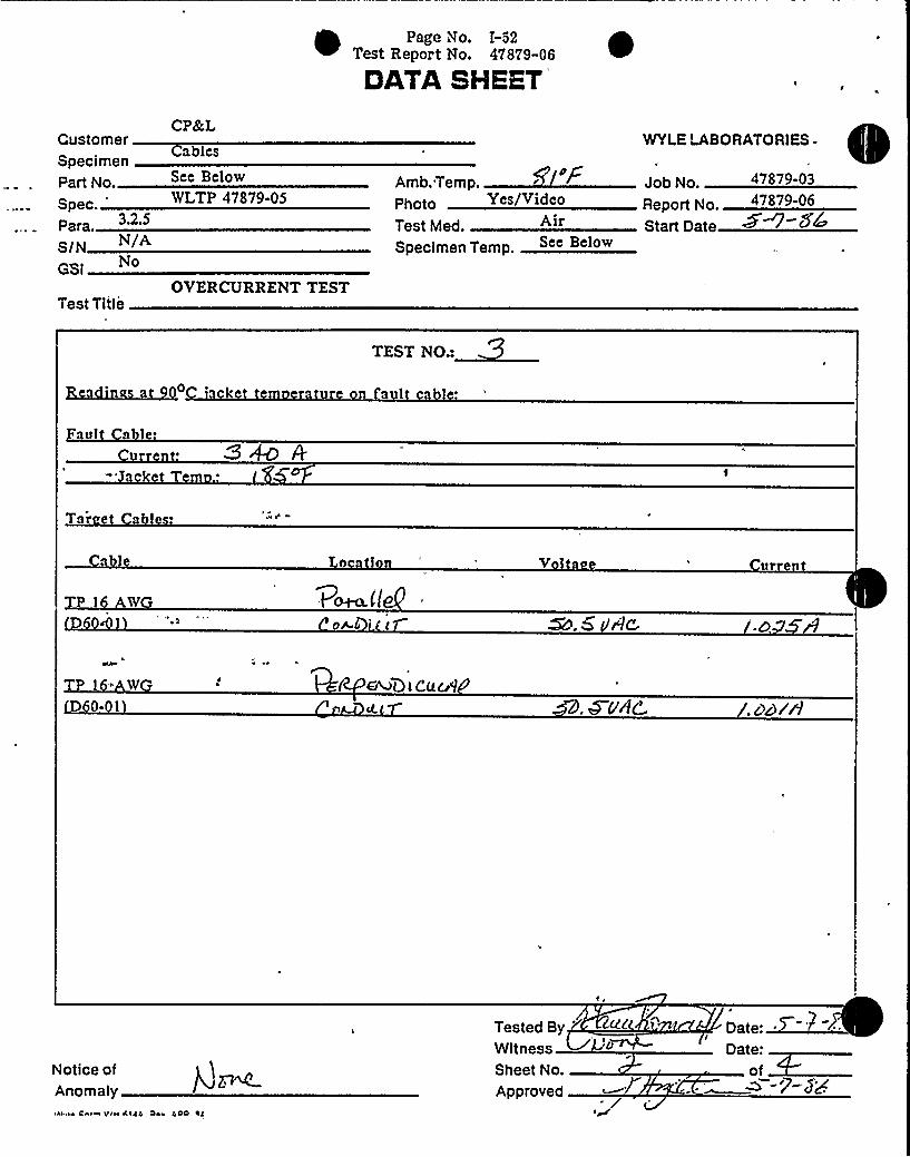
TEST NO.:
1 1
'ul
a le
Tar abl s. » 8
1 W
~.5 Ae -D
Tpl" W
D 0- I 8, WudC , ddt'h
Notice ofAnomaly
Tested By'itness
Sheet No.
Approved
Date: ~
I
of~ -7-$8

Page Vio. I-53Test Report Vio. 47879-06
DATASHEET
CP&LCustomer
Cablespecimen
part No See Below
Spec lVLTP 47879 05
ParaS/NGSI
OVERCURRENT TESTTest. Title
»YAmb. Temp.photo Yes Video
Test Med. AirSpecimen Temp. See Below
Job No.
Report No.
Start Date
47879-0347879-06
—WYLELABORATORlES
TEST NO.:
d'n wit cu re u c1'l
able:urren ' 3590 'AliYlC4
c er AD4WdOr ~ - 'P
Tare a le ~
a le pal n V la orren
l W
oM<li /.os r7
P AW
Notice ofAnomaly
L'ested ByWitnessSheet No.
Approved
Date: ~~Date:of~

Page Vo. T-54
1 Test Report Vio. 47879-06
DATASHEET
Customer"-Specimen.
Part No.
Spec. "
Para.N/A
GSi
Test Title
CP&L
Cables
Sec BelowWLTP 47879-05
OVERCURRENT TEST
Amb. Temp.Photo Ye Vi c
Test Med.
Specimen Temp. Sce Below
WYLELABORATORlES .
Job No.
Start Date
TEST NO.:~d' cur
quit able
C
~ ~
ncr u'. 3'Pl D
h r - 'rcuj
Tar e'' a l ~
V lta e urrent
i 'AKV
D 0-
i W
D 0-
Notice ofAnomaly
Tested By.WitnessSheet No.
Approved
SF'(C Yl pge . '.I/~i Date:
of ~-7-(T

Page VI o. I-55Test Repor t Vio. 47879-06
DATASHEKY
CP&LWYLELABORATORIESUstornef
cimenart No.
Spec.para 3.2.4 and .6
$ /N /AGSI
a es
OpAmb. Temp.
Yes/Video
Test Med.
Specimen Temp.
See Below Job No
Report No.
Start Date
WLTP 47879'-'05
Test Title p Q+~I~I FUNCTIONAL TEST
TEST NO.:~HIGH POTENTIAL TEST
Acceptance Criteria: There shall be no evidence of insulation breakdown or flashovcr with apotential of 1600 VAC applied for 60
seconds.'l
W
Fr
D.IV
h'ie'r«Shield Tied to Test Frame
No'tice ofAnomalyWyio Form WH SIAA. Roy. AFR 'SA
/Tested ByWitness ~™-Sheet No
Approved
Date:of
-7-5'w

1 Page Vi o. I-56Test Report Vio. 47879-06
DATASHEETCP8'cL
. Customera es
Specimen. See Below
WLTP 47879-05Spec.
3.2.4 and ,6Para.
SINGSI
Amb. Temp.Photo Yes/Video
Test Med.
Specimen Temp.
Job No.
Report No.Start Oate
47879-0347879-06
WYLELABORATORIES
Test TitleFUNCTIONALTESTCu~f
TEST NO.:
INSULATIONRESISTANCE TEST
Acceptance Criteria: Measured insulation resistance shall be greater than 1.6 megohms with 500VDC applied for 60 seconds.
L TI N
P~il@Qy ~c
E D
za"~2-
d /6
DW e 4'n b(cue.4Q o'W
rC
«Shield Tied to Test Frame
Notice ofAnomalyWvte Farm AH «la«. Rev. APR 'fQ
Tested By
Sheet No.
Approved
Date:of

TEST PROCEDUREt Page No. II-1
Test Report No. 47879-06
SGNRTITC STAYCKS8 SYSTEMS
LASORATORttS GROVPP: O. Boa 1008. Hunlavlllo. AL88807TWX 191 0I 9914888, Ptene g051 SSTmll DATE:
ApriI 30, 1986
TEST PROCEDURE NO. ~7/:jg
ELECTRICALRACEWAYSEPARATION VERIFICATIONTESTING
BETWEEN RIGID CONDUITSFOR THE
CAROLINAPOWER AND LIGHTCOMPANYFOR USE IN THE
SHEARON HARRIS NUCLEARPOWER PLANT—UNIT 1
:APPROVED BY
, . PROJECT MANAGER: 7
APPRovED BY ~ F. olmson
QUALITYENGINEER.
PREPARED BY .[)Va pe Hight
PROJECT ENGINEER:I
. T. Haze Ine
REVIS IDNS (jmk) FORM 1054-1 Rcv. 4I74
REV. NO. DATE PAGES AFFECTED BY APP'L, DESCRIPTION OF CHANGES
COPYRIGHI'Y WYLE LABORATORIES. THE RIGHT TO REPRODUCE, COPY, EXHIBIT, OR OTHERWISE UTILIZE ANY OF THE MATERIAL CONTAINED HEREINWITHOUT THE EXPRESS PRIOR PERMISSION OF WYLE LABORATORIES IS PROHIBITED. THE ACCEPTANCE OF A PURCHASE ORDER IN CONNECTION WITHTHE MATERIAL CONTAINED HEREIN SHALL BE EQUIVALENT TO EXPRESS PRIOR PERMISSION.

Page No. 1
Page No. II-2t7est Report Vto. 47879-06
Test Procedure No. 47879-05
SCOPE
This document has been prepared by Wyle Laboratories for the Carolina Powerand Light Company (CPttt:L) and encompasses the testing of physical separation,with respect to electrical faults, in representative configurations between rigidconduits or rigid conduits and cable at the Shearon Harris Nuclear Power Plant(SHNPP) —Unit 1.
This document details followwn testing of configurations not covered by WyleLaboratories Test Report No. 47879-02, Revision A, "Test Report on ElectricalSeparation Verification Testing for the Carolina Power and Light Company foruse in the Shearon Harris Nuclear Power Plant". It, therefore, serves asAppendix I to this r eport.
Objectives
The purpose of this procedure is .to present the requirements, procedures, andsequence to test the design adequacy of worst case configurations in thefollowing electrical separation situations:
~ Free Air Cables to Rigid Conduits containing Instrument or Control .Type Cables (see Figure 1)
e Parallel Rigid Conduits and Rigid Conduit to a Free Air Cable (seeFigure 2) ~
~
~ Perpendicular and Parallel Rigid Conduits (see Figure 3)
Applicable Documents—
Wyle Laboratories Test Report No. 47879-02, Revision A, "Test Report onElectrical Separation Verification Testing for the Carolina Power and LightCompany for use in the Shearon Harris Nuclear Power Plant".
IEEE Std. 383-1974, "IEEE Standard for Type Test of Class 1E Electric Cables,Field Splices, and Connections for Nuclear Power Generating Stations."
IEEE Std. 384-1974, "IEEE Trial Use Standard Criteria for Separation of Class 1EEquipment and Circuits."
United States Vtuclear Regulatory Commission Guide 1.75, Revision 1, "PhysicalIndependence of Electric Systems."
IEEE Std. 323-1974, "IEEE Standard for Qualifying Class 1E Equipment forNuclear Power Generating Stations."
Code of Federal Regulations, Section 10, Part 21.
Code of Federal Regulations, Section 10, Part 50, Appendix B.
WYI.E LABORATORIESHuntsville Facility

Page Vto. 2
Test Procedure No. 47879-05
Page tVo. II-3t Test Report Ão. 47879-06
SCOPE (Continued)
Equipment Description
This test procedure encompasses testing of the following IEEE Std. 383-1974qualified power, control, and instrumentation cables as described below.
Item No. Descri tionCable* COL
B/M**No.
Triplex 350 MCM
1/C 10 AWG
1 Pair 16 AUG
p
p
L
D25-10
D25-01
D60-01
P —Power Type CableL—Low Energy Type Cable
B/M = Billof Materials
Test Sequence"
The test program shall be performed in the following sequence:
~ Test Specimen IdentificationI
~ Conduit to Conduit and/or Free Air Cable Separation Tests
WYLE LABORATORIESHuntsville Facility

Page No. 3
Test Procedure No. 47879-05
Page No. II-4lTest Report No. 47879-06
2.0
2.1
2.1.1
TEST REQUIREMENTS
Acceptance Criteria
Insulation Resistance Test
Insulation resistance on the "target cables" ~ shall be greater than 1.6 x 10⁶ ohmswith a potential of 500 VDC applied for 60 seconds. Before testing insulationresistance from phase to conduit (shield), the shield to conduit continuity shall bemeasured with an ohmmeter. All Insulation Resistance Tests shall be performedas soon as practical after the Overcurrent Test.
2.1.2 H Potential Test
There shall be no evidence of insulation breakdown or flashover with a potentialof 1600 VAC applied for one minute.
"2.1-3 'Cable Continui Test
Energized specimens 'in the target raceway shall conduct 100% of NEC-ratedcurrents (see table below) at 50 VAC before, during, and after the overcurrenttest.
Cable ~ No. CPdtL - Cable RatedSize
'Conductors = IJ3. No. ~ ~Vol m Current
16 ANG 1 Tw. Pr. D60-01 L 50 VAC 1A
2.'1.4 Tolerances
All target cable voltages specified in this procedure shall be maintained within a+3% tolerance. All target cable currents shall be maintained within a +10%tolerance.
Allfault cable currents shall be maintained within a +3% tolerance.
„The term "target cablts" refers to energized and monitored nonfault cablesused in this program.
WYLE LABORATORIESHuntsvilla Facility

Page No. 4
Test Procedure No. 47879-05
Page No. II-5t Test Report No. 47879-06
, TEST PROGRAM
3.1 Test Specimen Inspection
An inspection of the test specimen cables and conduits shall be performed priorto starting the test program. This inspection shall verify that the specimens areas stated in Paragraph 1.3. Applicable manufacturer, part number, cable size,and cable B/M number shall be recorded on a Test Specimen Inspection Sheet.The test specimens shall be labeled as necessary to facilitate identificationthroughout the test program.
3.2 Conduit-conduit and/or Free AirTests
These tests shall consist of three individual tests between parallel rigid steelconduits and/or free air cables mounted 1/4-inch apart or inmontact at a pointwhen crossing. For Test 1, the target cable shall be wrapped around the 1-inchconduit containing the faulted cable. For Test 2, the target conduit shall be 1/4-inch above and parallel to the 3-inch fault conduit. In"addition, a free air cableshall drop 1/4-inch horizontally away from the fault conduit. For Test 3, thetarget conduits (2) shall touch the fault conduit, at a crossing point, and shall runparallel with 1/4-inch horizontal separation.
3.2.1 . Purpose
~ The purposes of these tests are to:
1. Demonstrate the acceptability of design where a control or instrumen-tation (low energy) conduit. is in-contact with a raceway or cable requiring.separation (Test 1).
2. Demonstrate the acceptability of design where a rigid conduit passes 1/4-inch horizontally or vertically away from a rigid conduit containing theworst case power-type cable (Tests 2 and 3).
3. Demonstrate the acceptability of design where a free air cable isphysically separated by 1/4-inch horizontally from a rigid conduitcontaining the worst case power-type cable (Test 2).
4. Demonstrate the acceptability of design where a rigid conduit touches, at apoint, a second rigid conduit containing the worst case power-type cable(Test 3).
WYLE LABORATORIESHuntsville Facility
Page No. 5
Test Procedure No. 47879-05
Page No. II-6est Report No. 47879-06
3.0
3.2
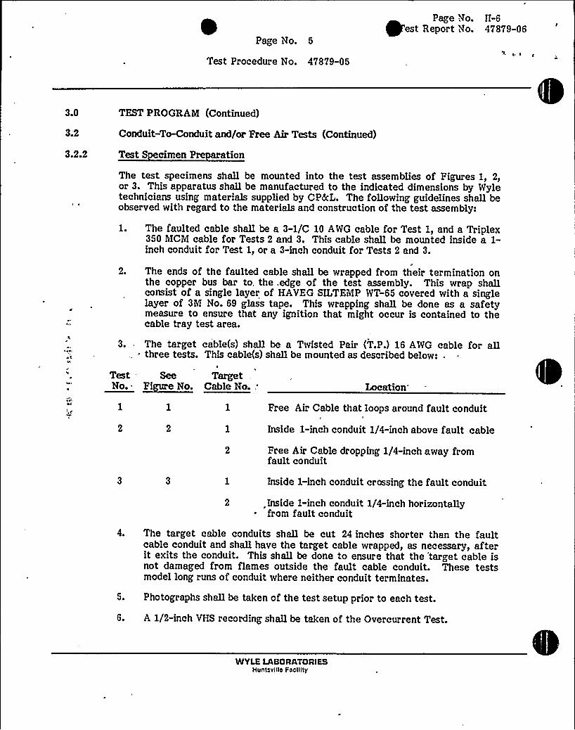
3.2.2
TEST PROGRAM (Continued)
Conduit-To-Conduit and/or Free AirTests (Continued)
Test S cimen Pre ation
The test specimens shall be mounted into the test assemblies of Figures 1, 2,or 3. This apparatus shall be manufactured to the indicated dimensions by Wyletechnicians using materials supplied by CPkL. The following guidelines shall beobserved with regard to the materials and construction of the test assembly:
The faulted cable shall be a 3-1/C 10 AWG cable for Test 1, and a Triplex350 MCM cable for Tests 2 and 3. This cable shall be mounted inside a 1-inch conduit for Test 1, or a 3-inch conduit for Tests 2 and 3.
20 The ends of the faulted cable shall be wrapped from their termination onthe copper bus bar to. the. edge of the test assembly. This wrap shallconsist of a single layer of HAVEG SILTEMP WT-65 covered with a singlelayer of 3M No. 69 glass tape. This wrapping shall be done as a safetymeasure to ensure that any ignition that might occur is contained to thecable tray test area.
3. The targetthree tests.
Test SeeNo. ~Fi e No.
cable(s) shall be a Twisted Pair (T.P.) 16 AWG cable for aQThis cable(s) shaQ be mounted as described below: .
TargetCable No..'ocation
Free Air Cable that loops around fault conduit
Inside 1-inch conduit 1/4-inch above fault cable
- Free Air Cable dropping 1/4-inch away fromfault conduit
Inside 1-inch conduit crossing the fault conduit
Inside 1-inch conduit 1/4-inch horizontally~ from fault conduit
4. The target cable conduits shaQ be cut 24 inches shorter than the faultcable conduit and shall have the target cable wrapped, as necessary, afterit exits the conduit. This shall be done to ensure that the target cable isnot damaged from flames outside the fault cable conduit. These testsmodel long runs of conduit where neither conduit terminates.
S. Photographs shaQ be taken of the test setup prior to each test.
6. A 1/2-inch VHS recording shall be taken of the Overcurrent Test.
WYLE LABORATORIESHuntsville Facility

Page No. 6
Test Procedure iVo. 47879-05
Page No. II-7Test Report No. 47879-06
3.0
3.2
TEST PROGRAM (Continued)
Conduit-To-Conduit and/or Free AirTests (Continued)
3.2 3
3.2.3.1
Instrumentation Setup
Thermocou le Locations
A total of 22 (Test 1), 30 (Test 2), or 35 (Test 3), Type "K" thermocouples shallbe utilized for these tests. The'thermocouples shall be mounted as describedbelow:
ChannelNo.
TestNo. Location
1-8
9@ 10
1-3
1-3
Mounted to the jacket on the fault cable. Thesethermocouples shall be mounted approximately 12inches apart.
Mounted to the conductor of the fault cables at thetwo series connections.
11-18
19-21
22-26
1-3, ~
1-3
2'
Mounted to the jacket of the target cable. ForTest 1, these thermocouples shall be between theconduit and the target cable. For Tests 2 and 3,these thermocouples shall be on the cable. in theconduit parallel with the fault conduit.
Mounted to the outside of the fault cable conduit.These thermocouples shall be spaced 24 inchesapart.
Mounted to the jacket of the target cableperpendicular to the fault conduit. One thermo-couple shall be at the crossing point and 2 thermo-couples mounted at 2 inches and 6 inches from thecrossing point.
27-29 2 8( 3 Mounted to the outside of the parallel target cableconduit. These thermocouples shall be mountedeven with Channels 19-21.
30-34
22 (Test 1) 1-330 (Test 2)
or 35 (Test 3)
Mounted to the outside of the perpendicular targetcable conduit. One thermocouple shall be mountedon the side at the crossing point and 2 thermo-couples mounted at 2 inches and 6 inches from thecrossing point.
Ambient temperatur e probe.
WYLE LABORATORIESHuntsville Facility

Page No. 7
Test Procedure No. 47879-05
Page No. II-8Test Report No. 47879-06
,3.0
3.2
3.2.3.1
TEST PROGRAM (Continued)
Conduit-To-Conduit and/or Free Air Tests (Continued)
Thermocou le Locations (Continued)'he
thermocouples shall be monitored by a Fluke Datalogger feeding a high-speed printer. The datalogger shall be operated at its maximum rate throughoutthe Overcurrent Test.
3.2.3.2 Electrical Monito
The voltages and currents of the target cables and the fault cable current shallbe fed into an oscillograph recorder. The oscillograph shall be operated at theO.l-inch per minute rate throughout the Overcurrent Test. The oscillographchannels shall be as specified in the following table..
Channel No. Test No.
1 '-32 1-3
3 2@34-9 '-3'0 1"3
Signal
Current
Voltage
Current
Skipped"
Current
Cable
T.P. 16 AWG Target CableT.P. 16 AWG Target Cable (Common)
T.P. 16 AWG Target Cable N2
N/AFault Cable
A digital multimeter shall be utilized to measure the voltages and currents ofthe target cables prior to, during, and after the Overcurrent Test. This datashall be recorded to provide accurate evidence of the speciinents capability toconduct rated current at 50 VAC throughout the Overcurrent Test.
3.2.4 Baseline Functional Tests
The baseline functional tests shall consist of insulation resistance and highpotential measutements on the target cables. These tests shall be performed asdescribed below.
3.2.4.1 Insulation Resistance Test
1. Disconnect the power and instrumentation leads from the target cables.
2. Measure and record shield-to-conduit resistance with a multimeter.
WYLE LABORATORIESHuntsville Facility

~ ~
Page Vto. 8
Test Procedur e No. 47879-05
Page Vto. II-9Test Report No. 47879-06
3.0 TEST PROGRAM (Continued)
3.2
3.2.4.1
Conduit-T~onduit and/or Free AirTests (Continued)
Insulation Resistance Test (Continued)
3. Using a megohmmeter, apply a potential of 500 VDC and record theminimum insulation resistance indicated after a period of 60 secondsbetween the following test points:
Tar et Instrument Cable:
Phase-to-Phase Phase-to-Ground
1 to 2 1 to shield*2 to shield*
Shield tied to conduit or unistrut frame.
„p a, arFor all performances of this test, the measured values shall be. compared to theacce tance criter I P agraph 2.1.1, i.e., greater than 1.6 x 10 ohms.
: 1." -Using a Hi-Pot Test. Set, apply.a-potential of 1600 VAC and record the'eakagecurrent observed after a period of 60 seconds between the
following test points:
Target Instrument Cable:
Phase-to-Phase Phase-to-Ground
1to2 1 to shield*2 to shield*
Shield tied to conduit or unistrut frame.
2. Reconnect all power and instrumentation leads.
For all performances of this test, the measured values shall be compared to theacceptance criteria, Paragraph 2.1.2, i.e., there shaQ be no evidence ofinsulation breakdown or flashover.
WYLE LASORATORIES- . Huntavllle Facility
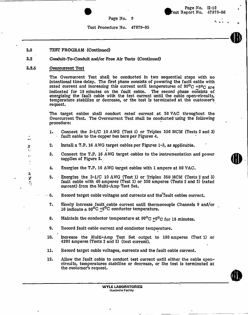
3.0
3.2
3.2.5
Page No. 9
Test Procedure Vo. 47879-05
TEST PROGRAM (Continued)
Conduit-To-Conduit and/or Free AirTests (Continued)
Overcurrent Test
Page tVo. II-10est Report No. 47879-06
~ g
The Overcurrent Test shall be conducted in two sequential steps with nointentional time delay. The first phase consists of powering the fault cable withrated current and increasing this current until temperatures of 90oC +5oC areindicated for 15 minutes on the fault cable. The second phase consists ofenergizing the fault cable with the test current until the cable open-circuits,temperature stabilize or decrease, or the test is terminated at the customer'request.
The target cables shall conduct rated current at 50 VAC throughout theOvercurrent Test. The Overcurrent Test shall be conducted using the followingprocedure:
1. Connect the 3-1/C 10 AWG (Test 1) or Triplex 350 MCM (Tests 2 and 3)fault cable to the copper bus bars per Figures 4.
2.
30
Install a T.P. 16 AWG target cables per Figur es 1-3, as applicable.
Connect the T.P. 16 AWG target cables to the instrumentation and powersupplies of Figure 5.
4. Energize the T.P. 16 AWG target cables with 1 ampere at 50 VAC.
5. Energize the 3-1/C 10 AWG (Test 1) or Triplex 350 MCM (Tests 2 and 3)fault cable with 40 amperes (Test 1) or 350 amperes (Tests 2 and 3) (ratedcurrent) from the Multi-AmpTest Set.
. 6. Record target cable voltages and currents and the fault cables current.
7. Slowly increase fault cable current until thermocouple Channels 9 and/or10 indicate a 90 C +5 C conductor temperature.
8. Maintain the conductor temperature at 90oC+5oC for ]5 minutes
9. Record fault cable current and conductor temperature.
10. Increase the Multi-Amp Test Set output to 180 amperes (Test 1) or4200 amper es (Tests 2 and 3) (test current).
11. Record target cable voltages, currents and the fault cable current.
12. Allow the fault cable to conduct test current until either the cable open-circuits, temperatures stabilize or decrease, or the test is terminated atthe customer's request.
WYLE LABORATORIESHuntsville Facility

Page No. 10
Test Procedure No. 47879-05
Page No. II-11
1 Test Report No. 47879-06
3.2
3.2.5
TEST PROGRA'M (Continued)
Conduit-To-Conduit and/or Free AirTests (Continued)
Overcurrent Test
13. Record time to ignition (or open-cir cuit), maximum fault cabletemperature recorded, and time current was applied to the fault cable.
14. Record target cable voltages and currents.
15. De-energize the target cables and the Multi-AmpTest Set.
16. Photograph the post-test condition.
3.2.6
For all performances of this test, the observed target cable operation shall becompared to the acceptance criteria, Paragraph 2.1.3, i.e., they shall maintaincontinuity of power.
Post Overcurrent Test Functional Test "
'he functional tests of Paragraph 3.2.4 shall be repeated on the target cables assoon as possible after the Overcurrent Test.
Quality Assurance
All test equipment and instrumentation to be used in the performance of thistest program will be calibrated in accordance with Wyle Laboratories'EasternOperations) Quality Assurance Program Manual, which conforms to theapplicable portions of ANSI N45.2, 10 CFR 50 Appendix B, 10 CFR 21, andMilitary Specification MIL-STD-45662. Standards used in performing allcalibrations are traceable to the National Bureau of Standards.
3.4 Report
Ten copies of the test report and one reproducible copy shall be issued,describing the test requirements, procedures, and results. The report shall be.prep'ared in accordance with the requirements of Section 8, Documentation, ofIEEE Std. 323-1974, as applicable.
WYLE LASORATORIESHuntsville Feclllty

i Page No. 11Test Procedure No. 47879-05
Page No. II-12tTest Report No. 47879-06
FAULT CABLE
UNISTRUT FRAME
1" OD CONDUIT
3-1/C 10 AWG FAULT CABLEIN 1" CONDUIT
T.P 16 AWG
TARGET CABLE
T P 16 AWG
TARGET CABLE(LOOP AROUND CON-DUIT TWO TIMES)
102" 120"
30"-
FRONT VIEW TOP VIEW
FIGURE 1: TEST NO. 1 SETUP

t Page No. 12Test Procedure No. 47879-05
Page No. II-13Test Report No. 47879-06
TRIPLEX 350 MCM FAULT CABLE
UNISTRUT FRAME
TiP ~ 16 AWG
FREE AIR CABLE
10
TRIPLEX 350 MCM
IN 3" CONDUITT.P. 16 AWG
ZN 1" CON DUIT
1" CONDUIT
3" CONDUITFREE AIR CABLE
1/4 ZNC 12 0 I1
30 II
FRONT VIEW TOP VIEW
FIGURE 2: TEST NO. 2 SETUP

Page No. 13Test Procedure No. 47879-05
Page No. 11-14est Report No. 47879-06
~ I
TRIPLEX 350 MCM FAULT CABLE
UNISTRUT FRAME
3" CONDUXT WXTH TRXPLEX350 MCM FAULT CABLE
1" CONDUIT WXTH T P.16 AWG TARGET
CABLES
1" CONDUIT
3" CONDUIT
102"
1/4 INCH
CROSSING CONDUITMOUNTED IN-CONTACTAT CROSSING POINT
60 II
120"
30 lt
FRONT VIEW TOP VIEW
PIGURE 3: TEST NO. 3 SETUP

FAULT CABLE IN CONDUIT
To Hul ti-amp TestSet
1/4" x 4" x 144" Copper Bus Bar
4
* The'three phases of the fault cable shall beconnected in series.
** The fault cable shall be wrapped with asingle layer of Siltemp WT No. 65 cover'edwith 3fl No. 69 glass tape from the edge ofthe test area to the bus bar.
rtd
OO
m QQlD lD
O O
tX)
COI
CD
FIGURE 4: TYPICALFAULTCABLE CONNECTIONS
Pt
qg '0o +~ UQrt O44

TllISTED PAIR 16 Alt)G
TARGET CABLE
IZO VAC
050 VAC
POTENTIALTRANSFORtlER
P vyPE "K" TIIERHOCOUPLE
MOUNTED TO JACKET
SllIELO
'0OAtbn. '0CGl <D
440 0
+ TO OSCILLOGRAPllRECORDER
SET TO 1 AHPERE
CURRENTTRANSFONtER
M CllOO
COI
C)CA
FIGURE 5: ELECTRICALCONNECTIONS FOR INSTRUMENTTYPE TARGEF CABLESqy '8tb
o~~ Ogr+ Q
440 0

SERIAL: iVLS-86-307
ATTACHMENT2
(4086SDC/vaw)

Lr,a
l
IIU
4lf

SHNPP FSAR
c ~ Test Results
The test results are detailed in Wyle Test Report No.47879-02. The minimum separation distances based on thetest results are detailed in Table 8.3.1.10.
27Where conduit separation distances are detailed inTable 8.3.1.10, it applies to any enclosed raceway(i.e., conduit, box, equipment enclosure, condulet,fitting, etc.).
(2) ~anal sis - Where the damage potential is containedwithin a conduit, and the Class LE cable(s) are in tray orare free air drop out cable, an analysis has been performedin accordance with the recommendations of Section 5.1.1.2 ofIEEE-384-1974 to justify a minimum separation distance of oneinch. The results of the analysis indicate that providedone-inch separation is maintained, any damage potentialassociated with the conduit will have no adverse affects onthe Class LE circuits.
(3) Installation of Barriers - Where the separationdistances could not be justified by test or analysis suitablebarriers/or approved protective coatings have been utilized,
. or cables have been installed in enclosed raceways which aresuitable for protecting the cables. The minimum separationdistance between enclosed raceways or between barriers andthe raceway/cable(s) is one inch.
(b) Cable and Raceway Hazard Areas — AnaLyses of the effects ofpipe whip, jet impingement, missiles, fire, and floodingdemonstrate that safety related electrical 'circuits, raceways, andequipment are not degraded beyond an acceptable level.
The analyses are referenced as follows:
High, Pressure .Piping
Missiles
Flammable Material
Flooding
(Section 3e6)
(Section 3.5)
(Section 9.5.1)
(Section 2.4)
In fire hazard areas outside the cable spreading rooms, whereredundant safety related trays or safety related and non-safetyrelated trays are exposed to the same fire hazard, protection hasbeen provided by spatial separation, fire suppression systems,fire retardant coatings, fire barriers, or combination thereof.
8.3.1-40 Amendment No. 27

SERIAL: MLS-86-307
The following are suitable barriers to meet the intent of IEEE-380:
(a)
(b)
(c)
Steel Tra Covers - Tray covers are utilized to pr otect any raceway/cable whichconverges within the separation window of the tray. A top cover is used to protectabove the tray and/or a bottom cover is used to protect below the tray.
~Firewra - A cable is firewrapped to protect any raceway/cable which convergeswithin the separation window of the cable.
Fireblanket —One-hour and three-hour blankets are installed to meet therequirements of Section 9.5.1. These blankets are acceptable barriers.
Also, I inch of fireblanket is, also equivalent to I inch of air. Since fireblankets aregreater than I inch thick, separation is not required between blankets andprotected raceways.
(40S6SDC/pgp)
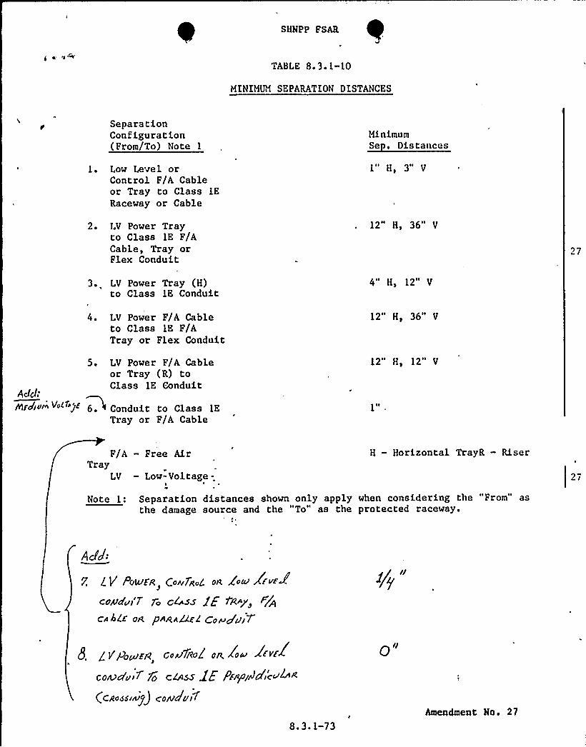
SHNPP FSAR
TABLE 8+F 1-10
MINIMUM SEPARATION DISTANCES
SeparationConfiguration(From/To) Note 1
MinimumSe . Distances
1. Low Level orControl F/A Cableor Tray to Class 1E
Raceway or Cable
2. LV Power Trayto Class 1E F/ACable, Tray orFlex Conduit
1~ I
H 3H
12" H, 36" V
27
3. LV Power Tray (H)to Class 1E Conduit
4" H, 12" V
Add:~gJjyg I/„l1iE
4 ~
5.
LV Power F/A Cableto Class IE F/ATray or Flex Conduit
LV Power F/A Cableor Tray (R) toClass 1E Conduit
Conduit to Class 1E
Tray or F/A Cable
12" H, 36" V
12" H, 12" V
F/A — Free AirTray
LV — Low-Volt
H — Horizontal TrayR — Riser
Note 1:
age-
Separation distances shown only apply when considering the "From" asthe damage source and the "To" as the protected raceway.
AJJ:
7. lY PuLc/FR Qwv7R L 0~ Zoccr JF~~ Jcoma'w'7 fa |"Ass JP tÃ~y
CA ALE oR pRRA&E'2 <0~+~qi"
8. iVg,~~a c.u1ied n. Zoo 2rvtlcoA7czu ~ jy c44ss lE PF+/JPic>™R
(cao~s.nip) care Jui1
8. 3. 1-73
o"
Amendment No. 27