ApolloSprayers Turbine Instruction Manual · 5 2. TrueHVLP™ Spray Finishing Systems...
50
1 ApolloSprayers Turbine Instruction Manual
-
Upload
phungkhuong -
Category
Documents
-
view
215 -
download
0
Transcript of ApolloSprayers Turbine Instruction Manual · 5 2. TrueHVLP™ Spray Finishing Systems...

1
ApolloSprayers Turbine Instruction Manual

2
1. Safety .............................................................................................................................................. 32. TrueHVLP™ Spray Finishing Systems ........................................................................................ 5
2.1 How Your HVLP Turbine System Works .............................................................................. 52.2 How Your Spray Gun Works.................................................................................................. 52.3 Preparing To Use Your HVLP Turbine System .................................................................... 62.4 Familiarize Yourself With Your TrueHVLP™ Turbine Spray Gun ....................................... 62.5 Get To Know Your Turbine .................................................................................................... 6
3. Apollo HVLP Turbines ................................................................................................................... 73.1 Apollo Turbine Models 725 and 835 .................................................................................... 73.2 Model 1035 .............................................................................................................................. 83.3 Model 1050 .............................................................................................................................. 83.4 Apollo Turbine Model 1050VR ............................................................................................... 93.5 Apollo Turbine Models 800S ............................................................................................... 103.6 Apollo Turbine Model 900 .................................................................................................... 103.7 Turbine Models 1100 And 1200 ........................................................................................... 11
4. Know Your Coatings ................................................................................................................... 124.1 Coating Properties ............................................................................................................... 124.2 Your Choice of Coatings and Viscosity ............................................................................. 124.3 Technique ............................................................................................................................. 14
5. Using Pressure Pots With Turbine Systems ............................................................................. 155.1 Testing Air Pressure in Pressure Pot ................................................................................. 165.2 Cleaning Pressure Pot ......................................................................................................... 16
6. Record Of Turbine Use ................................................................................................................ 177. Record Of Turbine Maintenance ................................................................................................ 178. Turbine Maintenance And Cleaning .......................................................................................... 18
8.1 Pre-Filter Maintenance - Models Except 800S ................................................................... 188.2 Filter Maintenance - Models Except 800S .......................................................................... 198.3 Filter Maintenance - Model 800S......................................................................................... 208.4 Annual Maintenance ............................................................................................................ 20
9. Running Multiple Spray Guns With A Turbine .......................................................................... 2110. Parts Lists .................................................................................................................................. 22
10.1 Model 725 ............................................................................................................................ 2210.2 Model 835 ........................................................................................................................... 2410.3 Model 900 ............................................................................................................................ 2610.4 Model 1035 .......................................................................................................................... 2810.5 Model 1050 .......................................................................................................................... 3010.6 Model 1050VR ..................................................................................................................... 3210.7 Model 1100 Chassis ........................................................................................................... 3410.8 Model 1100 Top ................................................................................................................... 3610.9 Model 1200 Chassis ........................................................................................................... 3810.10 Model 1200 Top ................................................................................................................ 4010.11 Model 4500 ........................................................................................................................ 4210.12 Model 4550 ........................................................................................................................ 44
11. Genuine Apollo Accessories .................................................................................................... 4612. Warranty ..................................................................................................................................... 49

3
Read all instructions and safety precautions before operating the unit.
^ DANGER
Indicates a hazardous situation, which, if not avoided, will result in death or serious injury.
^ WARNING
Indicates a hazardous situation, which, if not avoided, could result in death or serious injury.
^ CAUTION
Indicates a hazardous situation, which, if not avoided, could result in minor or moderate injury.
NOTICE
Indicates a situation that could result in damage to the equipment or other property.
^ WARNING
• Risk of fire or explosion! Solvent and paint fumes can explode or ignite, causing severe injury and property damage.
• Paints and solvents containing HALOGENATED HYDROCARBONS can react explosively with aluminum. Always check the product’s label before using these materials in the unit.
• Hazardous vapors: Paint, solvents, insecticides and other materials may be harmful if inhaled, causing severe nausea, fainting or poisoning.
• Make sure the room is well ventilated. Avoid all ignition sources, such as static electricity, sparks, open flames, hot objects, sparks from connecting and disconnecting power cords, and working light switches.
• Follow the material and solvent manufacturers’ safety precautions and warnings. Do not use liquids with flash points less than 100° F (38° C).
• Static electricity can be produced by HVLP spraying. Make sure any electrically conductive object being sprayed is grounded to prevent static sparking. The sprayer is grounded to prevent static sparking. The sprayer is grounded through the electrical cord.
• Use a respirator or mask whenever there is a chance that vapors may be inhaled. Read all instructions with the mask to ensure that the mask will provide the necessary protection against the inhalation of harmful vapors.
• Do not carry the turbine while spraying.
• Keep the turbine at the maximum distance from the spraying area.
1. Safety

4
NOTICE
• Tipping the spray gun causes the spray gun to clog. Dried spray material also clogs the pressure delivery tube and fittings. The spray gun does not function when clogging occurs.
• When not in use, be sure to disconnect the hose and place the spray gun into the Handi-Hold™ Docking Station on the turbine to avoid tipping.
^ DANGER
Improper installation of the ground plug can result in the risk of electrical shock. If repair or replacement of the plug or cord is necessary, do not connect the ground wire to either flat blade terminal. The wire with green insulation (with or without a yellow stripe) is the grounding wire.
1. For any question regarding proper installation of the ground plug, consult a qualified (licensed or certified) electrician.
2. Do not modify the plug provided. If the plug does not fit the outlet, have the proper outlet installed by a qualified electrician.
3. This product is for use on a nominal 110-volt circuit and has a grounding plug that looks like the plug in Figure 2. Make sure that the product is connected to an outlet having the same configuration as the plug. Do not use adapters with this product.
4. If an extension cord is required, use only a three wire extension cord that has the same configuration as the unit cord, including the (round) ground terminal. Make sure that the extension cord is plugged into a properly grounded receptacle.
5. When using an extension cord, be sure it is in good condition and heavy enough to meet the specifications in the chart below. If an extension cord is needed the following wire sizes must be used.
25’ cord (7.62m)…………………………............................ 10, 12, or 14 Gauge50’ cord (15.24m)………………………………................... 10 or 12 Gauge100’ cord (30.48m)………………………………………...... 10 Gauge
Grounding instructions for all countries using a 2 pronged plug configuration.
^ CAUTION
This product must be properly grounded. In the event of an electrical short circuit, grounding reduces the risk of electrical shock by providing an alternate path for the electrical current.
This product is equipped with a cord that has a ground wire and an appropriate ground plug. Plug the unit into an outlet that is properly installed and grounded in accordance with local codes and ordinances.
Safety Note: Users in countries in continental Europe and Australia and anywhere that offers a two pronged plug must be aware that this configuration does not provide grounding.
Figure 2

5
2. TrueHVLP™ Spray Finishing SystemsCONGRATULATIONS!! You have just purchased the finest HVLP air turbine system available. You are about to enjoy the great benefits of TrueHVLP™. Our designs are the result of many years experience in manufacturing HVLP turbine systems, and HVLP spray guns. We have painstakingly worked and consulted with professional spray finishers to bring you this versatile, well engineered tool.
Whether you are new to spray finishing, you have spray finished before, or are just new to HVLP spraying, there are some basic spray finishing guidelines that will help you to achieve the best results and optimum success from your new equipment. Reading this information carefully and following these simple steps will ensure that you get the best performance and results from your new TrueHVLP™ spray system.
Check the contents of your box. The following are included: Turbine Unit Spray Gun Air Hose Instruction Manual
2.1 How Your HVLP Turbine System WorksYour turbine system has three components: the turbine unit (1), spray gun (2) and air hose (3). The turbine unit, when connected to the correct electrical power supply and with the on/off switch in the “on” position, provides a continuous source of clean, warm, dry, High Volume Low Pressure (HVLP) air. The air hose connects the turbine unit to the spray gun. Air flows through the hose to the nozzle of the specially designed TrueHVLP™ spray gun. Atomization of the coating is achieved when the air mixes with the stream of fluid passing through the tip/nozzle. This low pressure atomization principle achieves minimum misting (overspray) to the spray environment.
2.2 How Your Spray Gun WorksApollo offers two types of Turbine Spray Guns. The 5000 series and the 7500 series. The 5000 series spray guns are bleeder style. When the turbine blower is turned “on”, air will constantly flow through the air cap. The 7500 series spray guns are non-bleeder style. When the turbine blower is turned “on”, air will only flow through the air cap when the trigger on the spray gun is activated or pulled back. Air also flows through the air feed tube to pressurize the cup and deliver fluid to the tip/nozzle. When the paint flow screw is opened and the trigger pulled back, fluid flows through the tip/nozzle mixing with the air flow delivered from the air cap and projects a fine atomized mist to your work piece. Spray pattern control will vary depending on the spray gun model. Consult your individual spray gun manual for detailed operation and maintenance of your spray gun.

6
2.3 Preparing To Use Your HVLP Turbine SystemConnect the air hose to the turbine. Pull back the spring loaded quick disconnect coupler and insert the male connector on the air hose into the turbine connector. Release the ring. Your air hose will be locked into place. To release the air hose, pull back on the spring loaded quick coupler ring with your fingers and pull. Connect other end of hose to spray gun using this same procedure. Plug power cord into an outlet that is properly installed and grounded in accordance with local codes and ordinances.
NOTICE
Do not cover or enclose the turbine. It is important to draw cool/ambient air through the unit for optimum performance. Avoid placing the turbine in a warm environment or in direct sunlight.
2.4 Familiarize Yourself With Your TrueHVLP™ Turbine Spray GunRefer to your Spray Gun Instruction Manual for information, setup and operation of your model spray gun.
You are now ready to spray your coating of choice on your work piece. Good quality results with your TrueHVLP™ spray finishing equipment are a combination of careful preparation of your project, a proper spraying environment, a basic knowledge of the coatings you will be using and how these coatings work with your TrueHVLP™ spray equipment.
^ CAUTION
Pressure will remain in the spray cup when unit is off. If you pull the trigger back, a stream of fluid will flow. To prevent accidents, turn material flow screw clockwise until it is completely closed. The trigger is now locked in the closed position.
Note: It is not necessary to empty and clean your spray gun when you pause between applications. Be sure, however, to clean your spray gun thoroughly at the end of your work session. Do not leave material in your spray gun overnight. Extra caution must be taken when spraying coatings that have a catalyst or hardener added. These coatings can harden in your spray gun quickly, making cleaning difficult or impossible. Read manufacturer’s coating instructions as to how much time you have before catalyst/hardener begins to set up.
2.5 Get To Know Your TurbineHandi-Hold™ Spray Gun Docking Station
Every model of Apollo Turbine except for the 800S and 1000S comes equipped with the Handi-Hold™ Spray Gun Docking Station (A), Apollo’s smart innovation. Store, hold or transport your spray gun in a vertical position with no risk of it falling over. Ready to spray when you are.
Disconnect hose from spray gun and insert coupler into the Handi-Hold™ Spray Gun Docking Station (A). as shown.

7
3. Apollo HVLP TurbinesEach TrueHVLP™ Turbine Unit offers the finisher a maximum operating pressure. This pressure is determined by the size and output of the unit you have selected. The maximum available pressure will have a direct bearing upon the viscosity of the fluid that you choose to spray. Atomizing pressure and fluid viscosity directly relate to the efficiency of the equipment operation and the quality of the results that you will achieve.
The available air volume and pressure at the air cap of the spray gun will meet the delivery of fluid coming out of the nozzle to create a fine mist called atomization. This mist travels directly to your work piece where it blends together to form a connected wet film. Achieving a smooth, level surface will depend on the proper relationship between available atomizing pressure, the viscosity of the coating being applied and the properties of the coating.
3.1 Apollo Turbine Models 725 and 835
Model 725Model 725
Hi Power 2-Stage Turbine4.5 psi (0.31 bar) sealed*112 cfm (3.17 cmm)Dual air filtrationSingle spray gun110 - 120 volts, 60Hz, 10 amps, 1.5H.P.220 - 240 volts, 50Hz, 5 amps, 1.5H.P.Weight: 19lbs (8.6kg)Height: 11" (27.94cm)Width: 7.25" (18.41cm)Length: 11.25" (28.58cm)
All EU units shipped
All 110 volt units aretested and certified.
Model 835Model 835
3-Stage Turbine7.0 psi (0.48 bar) sealed*115 cfm (3.25 cmm)Dual air filtrationSingle spray gun110 - 120 volts, 60Hz, 10 amps, 1.5H.P.220 - 240 volts, 50Hz, 5 amps, 1.5H.P.Weight: 29lbs (13.2kg)Height: 12" (30.48cm)Width: 8.5" (21.6cm)Length: 15" (38.1cm)
All EU units shipped
All 110 volt units aretested and certified.
725 Shown With 7500MT Spray Gun
835 Shown With 7500QT Spray Gun

8
3.2 Model 1035Model 1035
4-Stage Turbine9.0 psi (0.62 bar) sealed*130 cfm (3.68 cmm)Dual air filtrationSingle spray gun110 - 120 volts, 60Hz, 13 amps, 1.85H.P.220 - 240 volts, 50Hz, 6 amps, 1.75H.P.Weight: 30lbs (13.6kg)Height: 12” (30.48cm)Width: 8.5” (21.6cm)Length: 15” (38.1cm)
All EU units shipped
All 110 volt units aretested and certified.
3.3 Model 1050Model 1050
5-Stage Turbine9.5 psi (0.70 bar) sealed*130 cfm (3.68 cmm)Dual air filtrationSingle spray gun110 - 120 volts, 60Hz, 13 amps, 1.85H.P.220 - 240 volts, 50Hz, 8 amps, 1.75H.P.Weight: 31lbs (14.1kg)Height: 12” (30.48cm)Width: 8.5” (21.6cm)Length: 15” (38.1cm)
All EU units shipped
All 110 volt units aretested and certified.
1035 Shown With 7500QT Spray Gun
1050 Shown With 7500QT Spray Gun

9
1050VR Shown With 7500QT Spray Gun
5-Stage Turbine 9.5 psi (0.70 bar) sealed* 130 cfm (3.68 cmm) Dual air filtration Single spray gun 110 - 120 volts, 60Hz, 15 amps, 1.85H.P. 220 - 240 volts, 50Hz, 8 amps. 1.75H.P. Weight: 31lbs (14.1kg) Height: 12” (30.48cm) Width: 8.5” (21.6cm) Length: 15” (38.1cm)
All EU units shipped
All 110 volt units are tested and certified
3.4 Apollo Turbine Model 1050VRThe model 1050VR is part of the new Power + Precision Series by Apollo Sprayers International, Inc. Apollo’s Precision Air Control Technology (PACT) allows you to control the air pressure from the turbine to within 1/10th of a PSI. The 1050VR comes supplied with one spray gun and hose. The unit has the capability to run two spray guns using the optional “Y” connector (Part #A4227).
There is a single switch located on the front of the 1050VR turbine. This switch can be used in the “Variable Pressure” or UP position to operate the variable speed and LCD pressure display screen. The switch can also be used in the “Fixed Pressure” or DOWN position to bypass the control board and run the motor at 100% full power.
To control the air pressure on the 1050VR turbine, connect the spray gun and hose with the turbine. Plug the turbine into the appropriate voltage for your model. Move the switch to the UP or “Variable Pressure” setting. The factory has preset your turbine speed at the maximum speed. To get an accurate pressure reading it is advised that you let the turbine warm up for about 5 minutes. Once the turbine motor is warm the LCD will give you an accurate pressure reading.
The control board will automatically adjust the motor speed to compensate for barometric pressure and elevation. The pressure reading will always be accurate. To decrease the pressure from the maximum setting simply turn the knob underneath the LCD pressure display counter-clockwise. To increase the pressure once reduced, turn the knob clockwise. As you turn the knob, the pressure will increase or decrease accordingly.
The viscosity of the coating you want to spray will determine the amount of pressure needed. The thicker your viscosity, the more pressure you will need to atomize your coating. For highest efficiency, use the lowest pressure that produces the best atomization and finish results. If you experience “Orange Peel”, increase the pressure. If you have too much overspray, decrease the pressure.
The 1050VR also has a filter warning system. The filter warning system works in conjunction with the Variable Pressure switch in the ON or UP position. This will prevent overheating your motor. To prevent damage to the motor the warning light will first turn from GREEN to RED.
NOTE: If the warning light is ignored and the motor is still used without changing or replacing the filters the turbine will turn off automatically. The system cannot be turned back on until the temperature of the motor cools down dramatically. If this happens, immediately check both the filters and pre-filters for a blockage. Once the filters have been cleaned or replaced and the motor has cooled down the turbine will reset itself. Once the turbine has reset it is safe to use again. DO NOT use “Fixed Pressure” setting to override the control board, this will cause damage to your motor and void your warranty. If the turbine has shut down, clean the filters and let it sit, DO NOT ignore the light.
*All turbine pressures quoted are measured sealed and at the motor outlet. Actual spraying pressures will vary depending on the model and size of the turbine.

10
3.5 Apollo Turbine Models 800SModel 800S has one air hose outlet on the side of the unit and is designed to run one spray gun. This model DOES NOT have an internal air relief valve installed. To use a non-bleed style spray gun with this unit (Apollo Model # A7500) it is necessary to install Part #A7538 - External Air Relief Valve. Failure to install this part when using a non-bleed turbine spray gun can cause premature motor failure and will void all warranty.
Model 800S
800S 3–Stage Turbine5.5 psi (0.38 bar) sealed*115 cfm (3.25 cmm)Dual air filtrationSingle spray gun110 - 120 volts, 60Hz, 11 amps, 1.65H.P.220 - 240 volts, 50Hz, 5.5 amps, 1.65H.P.Weight: 29lbs (13.2kg)Height: 12” (30.48cm)Width: 8.5” (21.6cm)Length: 15” (38.1cm)
All EU units shipped
All 110 volt units aretested and certified.
3.6 Apollo Turbine Model 900Model 900 has two independent air outlets. This unit is supplied with one outlet capped. To use two spray guns at the same time, the cap needs to be removed and a quick disconnect coupler installed (part #A2070). When using only one spray gun, always be sure that one outlet is capped. This model DOES NOT have an internal air relief valve installed. To use a non-bleed style spray gun with this unit (Apollo Model A7500) it is necessary to install Part #A7538 - External Air Relief Valve. Failure to install this part when using a non-bleed turbine spray gun can cause premature motor failure and will void all warranty.
Model 900
Hi Power 3-Stage Turbine6.0 psi (0.41 bar) sealed*120 cfm (3.40 cmm)Dual air filtrationDual spray gun capability110 - 120 volts, 60Hz, 12 amps, 1.75H.P.220 - 240 volts, 50Hz, 6 amps, 1.75H.P.Weight: 34lbs (15.4kg)Height: 15” (38cm)Width: 13” (33cm)Length: 17” (43cm)
All EU units shipped
All 110 volt units aretested and certified.
900 Shown With 5510 Spray Gun

11
3.7 Turbine Models 1100 And 1200Models 1100 and 1200 have three independent air outlets on the back of the unit with the option of running one, two or three spray guns at the same time. The units come supplied with one outlet with a quick disconnect coupler and two outlets capped. It is necessary to uncap each extra outlet and attach a quick disconnect coupler (Part #A2070) when operating additional spray guns. Always be sure to cap any unused air outlet.
There are two switches on the model 1100 and three switches on the model 1200. Machine Off: all switches in Off position. Low Power (3psi): right switch in On position. Medium Power (6psi): right switch in Off position and left switch in On position. (Two cooling fans located behind the two rectangular filters in the front of the unit operate automatically). High Power (10psi): left and right switch in On position. Both cooling fans operate automatically. The Model 1200 operates the same as the Model 1100, but adds a 2.5 gallon (10 litre) pressure pot, a platform for the pressure pot, plus an automatic fluid feed system. This gives the option of continuous production spraying. The Model 1200 contains a grounded outlet for the automatic fluid feed system, which is operated by the third switch (far left) on the unit. See Using Pressure Pots for additional information.
As a general guide, use low power for thin viscosity materials, medium power for slightly thicker coatings and high power for thicker/heavier viscosities. Refer to viscosity chart (D) or call Apollo technical support 888-900-4857 for further information.
Model 1100
Three Separate Power Levels:Low: 3.5 psi (0.24 bar) 94 cfm (2.66 cmm) sealed*Medium: 6.0 psi (0.41 bar) 120 cfm (3.40 cmm) sealed*High: 10 psi (0.69 bar) 200 cfm (5.66 cmm) sealed*Five Air FiltersThree spray gun capability110 - 120 volts, 60 Hz, 17 amps, 2.6H.P. 220 - 240 volts, 50 Hz, 9 amps, 2.6H.P.Weight: 60lbs (27.2kg)Height: 17” (43cm)*Width: 18” (46cm)Length: 26” (66cm)* Handle increases height.
All EU units shipped
All 110 volt units aretested and certified.
Model 1200
Three Separate Power Levels:Low: 3.5 psi (0.24 bar) 94 cfm (2.66 cmm) sealed*Medium: 6.0 psi (0.41) 120 cfm (3.40 cmm) sealed*High: 10 psi (0.69 bar) 200 cfm (5.66 cmm) sealed*Five Air FiltersThree spray gun capability110 - 120 volts, 60 Hz, 17 amps, 2.6H.P.220 - 240 volts, 50 Hz, 9 amps, 2.6H.P.Weight: 89lbs (40.4kg)Height: 42” (107cm)*Width: 18” (46cm)Length: 26” (66cm)* Handle and pressure pot increase height.
All EU units shipped
All 110 volt units aretested and certified.
Model 1100Model 1200
1200 Shown With 7500T Spray Gun
1100 Shown With 7500GT-600 Spray Gun

12
4. Know Your Coatings
4.1 Coating PropertiesCoatings are a blend of resins and additives to create a product that will provide a protective and beautifying surface to your work piece. Different resins have different properties. It is important to use the correct coating to achieve a desired result. Manufacturers of coatings can control the resin solids content, production viscosity, sheen, color, flow-out enhancement and other properties. Some products offer ways to adjust the coating properties such as speeding up or slowing down the drying time, adding catalysts to strengthen the molecular bond or adding flatting agents to lower the sheen. Manufacturers will often give some guidelines on how to thin their product for spray application. There are many different types of spray equipment in use. Coatings manufacturers cannot address all of them. It is important for the finisher to understand the spray equipment and to use common sense to arrive at the correct fluid viscosity to produce the best possible results with the selected coating and the equipment being used.
4.2 Your Choice of Coatings and ViscosityExtremely thin, watery or light bodied fluids such as inks, aniline dyes and oil stains can generally be used straight from the can. RTS or Ready to Spray water based finishing products are formulated to be used straight from the can without thinning with a 3 stage or larger turbine. Most other coating products will need to be thinned anywhere from 10% to 50% depending on the available air pressure of the turbine model and the properties of the coating selected. (see chart below).
Chart A Turbine PerformanceTurbine Size Sealed Air Pressure Coating Types
2 STAGE 4.5PSI Low Viscosity Materials Only3 STAGE 7.0PSI Low-Medium Viscosity Materials4 STAGE 9.0PSI Low-High Viscosity Materials5 STAGE 9.5PSI Low-High Viscosity Materials
Dual Turbine 10PSI (At full power) Low-High Viscosity Materials Using Latex (Emulsion) Paint
Although your turbine spray system is best suited to spray Class A Finish coatings such as lacquers, enamels, urethanes, varnishes, waterborne and water base etc., you can spray latex (emulsion) house paint if you follow a few simple rules. First, it is generally necessary to thin latex (emulsion) paint. This will vary from as little as 10% to as much as 50% depending on the model turbine you are using and the quality of the paint used. Second, it is necessary to use a larger nozzle and needle set in the spray gun (2.0mm or 2.5mm). It is recommended that a latex (emulsion) paint conditioner like Floetrol®, be added to aid flow-out. These products are sold at local paint stores.
Chart B Nozzle, Needle And Air Caps For 5000 Series Spray Guns
Tip/Needle Size Application Air Cap.75MM (.0295)(#1) Inks, Dyes, Stains, extremely thin
viscosity fluids, Water based finishes (A) #A5201
1.0MM (.039) (#2) All purpose, thin lacquers, thin enamels, Water based finishes, Automotive, Marine, Airplane
finish
(A) #A5201
1.5MM (.059) (#3) Catalyzed lacquers, Conversion Varnish, Water based finishes, Primers, Automotive, Marine,
Airplane, finish Varnish, High Viscosity Industrial Coatings, Urethanes, Enamel
(A) or (B) #A5201 #A5297
2.0MM (.079) (#4) Thinned latex paint, Multi-spec,Heavy Primers, Butyrate, nitrate dope, High
Viscosity Industrial Coatings
(B) #A5297
2.5MM (.098) (#5) Thinned latex paint, Multi-spec,Solvent adhesives, Wax based strippers
(B) #A5297
13
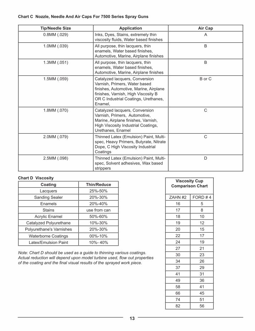
Chart C Nozzle, Needle And Air Caps For 7500 Series Spray Guns
Tip/Needle Size Application Air Cap0.8MM (.029) Inks, Dyes, Stains, extremely thin
viscosity fluids, Water based finishesA
1.0MM (.039) All purpose, thin lacquers, thin enamels, Water based finishes, Automotive, Marine, Airplane finishes
B
1.3MM (.051) All purpose, thin lacquers, thin enamels, Water based finishes, Automotive, Marine, Airplane finishes
B
1.5MM (.059) Catalyzed lacquers, Conversion Varnish, Primers, Water based finishes, Automotive, Marine, Airplane finishes, Varnish, High Viscosity B OR C Industrial Coatings, Urethanes, Enamel,
B or C
1.8MM (.070) Catalyzed lacquers, Conversion Varnish, Primers, Automotive, Marine, Airplane finishes, Varnish, High Viscosity Industrial Coatings, Urethanes, Enamel
C
2.0MM (.079) Thinned Latex (Emulsion) Paint, Multi-spec, Heavy Primers, Butyrate, Nitrate Dope, C High Viscosity Industrial Coatings
C
2.5MM (.098) Thinned Latex (Emulsion) Paint, Multi-spec, Solvent adhesives, Wax based strippers
D
Chart D Viscosity Coating Thin/ReduceLacquers 25%-50%
Sanding Sealer 20%-30%Enamels 20%-40%Stains use from can
Acrylic Enamel 50%-60%Catalyzed Polyurethane 10%-30%
Polyurethane's Varnishes 20%-30%Waterborne Coatings 00%-10%Latex/Emulsion Paint 10%- 40%
Note: Chart D should be used as a guide to thinning various coatings. Actual reduction will depend upon model turbine used, flow out properties of the coating and the final visual results of the sprayed work piece.
Viscosity Cup Comparison Chart
ZAHN #2 FORD # 416 517 818 1019 1220 1522 1724 1927 2130 2334 2637 2941 3149 3658 4166 4574 5182 56

14
4.3 TechniqueLike any skill, practice makes perfect. Never try to rush the spray finishing process. Learn the characteristics of the coating you will be spraying. Build up layers of material (3-4 applications or more if necessary). Sand between coats and allow proper drying time between applications.
Some rules for effective spray finishing:
1. Remember to always keep the distance between the spray gun and the surface the same when moving across your work, (or up and down) called a “pass”. Do not rotate or turn your wrist from side to side.
See Chart E Below
2. Move the spray gun across your work from end to end.
3. Be sure to maintain the same speed of movement. This ensures an even application of coating.
4. At the end of a “pass” always release the trigger. To continue, spray in the opposite direction and overlap your previous coat by 1/3 to 1/2.
5. When finished you should have an even wet coat on your work. If you have dry spots you have overlapped too wide. If you have heavy or wet spots, you have overlapped too much or sprayed too slowly.
6. When spraying a large or pre-assembled piece, start at the top and work down.
7. Try to spray the hard to reach and underneath surfaces first.
Common sense and some forethought will prevent errors. Remember, that a light wet film will generally produce better results than a heavy wet coat. When spraying a vertical surface it is advisable to apply a thin/light “tack” coat first, followed by a normal light wet coat. This technique will help prevent “runs” and “sags”. Chart E Spray Gun Technique
When using your Spray Gun you control five variables:1. Fluid flow.
2. Distance of the spray gun from your work. 4”-8” (10-20cm) is average. Closer if necessary.
3. Pattern direction (vertical fan, horizontal fan and round).
4. Speed of application.
5. Fan pattern size. 7500 series with Fan Pattern Control Ring. 5000 series move the spray gun closer to or further away from workpiece.
NOTE: Items 1,2, and 4 directly relate to each other.
Cleaning Your TrueHVLP™ Spray Gun
Refer to your spray gun manual for cleaning and maintenance of your spray gun model.

15
5. Using Pressure Pots With Turbine SystemsThere are many advantages to using pressure pots with a turbine system. Apollo Sprayers have made this very easy withour fluid feed systems, 4500 and 4550. Refer to the accessories section of this manual for more information on these andother products. By removing the paint cup from the spray gun you immediately reduce the overall weight of the spray gunby ½. You also get a smaller tool to hold in your hand thereby allowing you to more easily access the back of cabinets or other tight spaces where a standard cup gun would not fit. By using a pressure pot you are able to spray larger quantities of material without stopping to refill a smaller cup. This can save a lot of time on a long job where you are spraying the same material all the time.
Using a pressure pot with any size turbine system is very easy. All you need is any sizepressure pot, a fluid hose and a small air compressor. When using a remote cup orpressure pot, it is necessary to introduce compressed air in order to pressurize the remote pot and move the fluid from the pot to the spray gun tip/nozzle. In general 5PSI (0.345 Bar) of air pressure is adequate to push most average viscosity fluids to the spray gun nozzle. Higher pressure would only be necessary for heavier viscosity fluids or if you are spraying up a ladder where the fluid has to travel more than 6 feet of elevation.
Connect the black fluid hose to the fluid outlet on the top of the pressure pot. Refer to your pressure pot instructions for the specific location of the fluid outlet. Seal the threads with Teflon tape and tighten with a wrench (spanner) to assure no fluid leaks once you pressurize the pot. Next, connect the air line from your compressor to the air inlet. This should be a male quick connect adjacent to the regulator and gauge. If your quick connect is the same style as the one on the pot you can pull back the ring on the female end and insert into the male end, releasing the ring to fasten them together. Connect the other ends of the fluid line and air line to the spray gun and air compressor respectively. Your turbine air hose will connect as normal directly to your spray gun. Refer to your spray gun instruction manual for more specific instructions.
Part #A4900 - 2.5 gallon (10 litre) deluxe pressure pot. Part #A4600 - 2 quart (2 litre) pressure pot.

16
5.1 Testing Air Pressure In Pressure PotIt is necessary to test the air pressure in the pressure pot to make sure that it is appropriate for the viscosity of materialbeing sprayed and the situation in which it is being sprayed. You don’t want the material coming out too quickly so thatyou get runs and sags, but you also don’t want it to come out too slowly so that you are spraying very slowly. To test theair pressure in the pressure pot follow these simple instructions:
1. DO NOT turn on the turbine at this time.
2. Make sure your air hose and material hoses are connected appropriately to the pressure pot.
3. Turn on your air compressor and wait until you have about 5PSI (0.345 Bar) in the pressure pot. Then, pull thetrigger on the spray gun until a stream of fluid flows from the tip/nozzle. NOTE: This may take a few minutesdepending on the length of your fluid hose.
4. Adjust the pressure on the pot regulator until the fluid drops off or bends at approximately 2-1/2 “ (6.35cm).
5. Your pot air pressure should be correct at this point, however, if the stream bends too short then increase the airpressure. If the stream bends too far, then reduce the air pressure. If you need additional help, please feel freeto call our technicians at 1-888-900-4857.
^ CAUTION
Depressurize pressure pot using safety valve when equipment will be idle for a while.This will prevent excess fluid from remaining in fluid hose, and prevent a possible accidentif the trigger is pulled causing material to stream from the spray gun.
Always ensure that the remote pot is tightly sealed, and all gaskets are in good shape, to prevent air and fluid leaks. Besure to flush and clean the fluid hose at the end of a work session. For smaller jobs, insert a one gallon can inside the 2.5gallon (10 litre) pressure pot. This will help to keep the inside of the pot cleaner.
NOTE: It may be necessary to provide extra clearance by removing the filter on the bottom of the pickup tube for somepaint cans to fit inside the 2.5 gallon (10 litre) pressure pot.
5.2 Cleaning Pressure PotCleaning your pressure pot is important to many years of long faithful service. If you don’t clean your pressure pot it willeventually get clogged up with dried material from previous jobs. Make sure you not only clean your pressure pot well,but do it quickly after you are done spraying so as to reduce the amount of time the material has to dry. To clean your pressure pot follow these simple instructions:
1. Remove the lid and pour your remaining finish back into your can or if you have reduced it, into a differentcontainer for storage.
2. Pour solvent or water (depending on the type of finish you have used) into the pressure pot and reseal the lid.
3. Re-pressurize the pressure pot with air.
4. Turn on your turbine and pull the trigger on the spray gun fully open until the material comes out clean.
5. Remove the lid once again and pour out any unused water or solvent.
6. Wipe the inside of the pressure pot, pickup tube and lid with a clean rag.
7. If you use waterbased materials, dry the pressure pot.
8. Store in a clean dry place for use next time.

17
Record Of Turbine UseModel Serial # Date Purchased
Date Hours Of Use Total Hours
Turbine Recommended Maintenance: Clean and/or change pre-filters and/or cartridge filters every 50 hours or when necessary. See Accessories Page for appropriate filter replacement for your model.
7. Record Of Turbine Maintenance Record Of Turbine Maintenance
Date Maintenance Performed
6. Record Of Turbine Use

18
8. Turbine Maintenance And Cleaning
^ CAUTION
Always unplug your turbine from the main electrical supply before doing any maintenance or repairs.
After Each Use:
Your Apollo turbine system requires very little maintenance. The turbine motor has sealed bearings that are lubricated for life. The only maintenance that you will need to perform is checking, cleaning and replacing your filters and pre-filters as required. It is very important that your motor has cool, clean air to operate efficiently. If you maintain your filters and pre-filters well, you will enjoy many years of long service from your turbine motor.
NOTICE
Always use genuine Apollo filters and pre-filters. Other types of filters and pre-filters may prevent proper air flow to the motor, resulting in premature motor failure and voiding your warranty.
8.1 Pre-Filter Maintenance - Models Except 800SWe recommend that you remove your pre-filters after each use. To remove the pre-filters: push your finger between the filter (1) and pre-filter (2) until you can curl it up and pull the pre-filter off, rotating your finger around the pre-filter as you pull. Do not pull hard as you will break the glue line on the pre-filter. Make sure you check both pre-filters as they can get dirty at different intervals. If they appear to be a little dirty or clogged, you can wash them out using a mild soap and warm water. If they are not cleanable you need to install new pre-filters.
To reinstall the pre-filters, hold one in both hands and apply the top first, moving your fingers around the inside as you slide it back over the filter cartridge from top to bottom. NEVER operate your turbine without both filters and pre-filters installed and clean.

19
8.2 Filter Maintenance - Models Except 800SVisually check your filters when you remove your pre-filters for cleaning. Check for accumulated material in the filter element. If you suspect they may be dirty, or if you can see material building up, don’t take a chance, remove the filter and hold it up to the light.
To remove your filters, remove two dome nuts (1) and pull filter plate (2) off. Filter plate can hang up on the threads so make sure you pull it off straight. Remove filter (3). If filter is stuck to the side of the case, gently tap them with your hand.
To check your filters, hold them up to a light, similar to your car air intake filter. If you cannot see light through more than 50% of the filter, replace filter element.
NOTICE
Filter element may be damaged if more than 50 PSI of air pressure is used to blow out filter element.
If they appear to be dirty, you can tap them gently on a flat surface to remove any debris. If you have compressed air available, you can also blow them off with air. If you use compressed air to clean your filters, make sure you blow the air from the inside out and never use more than 50 PSI or this will damage the filter element.
To reinstall the filters, reverse the instructions above. Make sure that you line the filter up with the filter plate first, this will help to keep it straight when replacing the dome nuts.

20
8.3 Filter Maintenance - Model 800STo replace filters on the model 800S, remove the two hex-head nuts (1). Remove filter (2). Periodically wash and blow excess dust and dirt with water and an air compressor. Dirty filters will reduce the air being drawn through the motor, causing the unit to run abnormally hot, diminish spray performance, and reduce the life of the motor. Clean and/or replace filters when you suspect they can no longer be cleaned. Use the maintenance record sheet to keep track of your equipment use.
To check your filters, hold them up to a light, similar to your car air intake filter. If you cannot see light through more than 50% of the filter, replace filter element.
NOTICE
Filter element may be damaged if more than 50 PSI of air pressure is used to blow out filter element.
If they appear to be dirty, you can tap them gently on a flat surface to remove any debris. If you have compressed air available, you can also blow them off with air. If you use compressed air to clean your filters, make sure you blow the air from the inside out and never use more than 50 PSI or this will damage the filter element.
To reinstall the filters, reverse the instructions above.
8.4 Annual MaintenanceCheck carbon brushes at least once a year or every 300 hours, which ever comes first. To check your carbon brushes consult with an authorized Apollo repair facility.

21
9. Running Multiple Spray Guns With A TurbineApollo Turbine Models 725, 835, 1035, 1050 and 1050VR have one air hose outlet on the side of the unit and aredesigned to run one spray gun. These models are equipped with an internal air relief valve to accommodate a non-bleedstyle spray gun (Apollo Model 7500).
It is possible to run a 4 or 5-stage turbine system with two spray guns at the same time by installing Part #A4227, theoptional “Y” Connector, to the turbine outlet port. It is important to note that if the “Y” Connector is installed and only onespray gun is operated, the 2nd outlet must be capped or closed so that performance to the single spray gun will not beaffected. To install the A4227, “Y” connector follow these instructions:
1. Unscrew the female quick connect from the air outlet located on the side of your turbine.
2. Screw on the “Y” connector. Make sure the “Y” is sideways so you can easily attach your hoses.
3. Screw the female quick connect you removed from your turbine onto the “Y” connector. If you plan on usingtwo spray guns right away, then make sure you have a 2nd “Y” connector installed on the unused side of the “Y”connector.
4. You are now ready to connect your air hoses and spray guns.
Remember, we do not recommend using the “Y” connector with turbines smaller than 4 or 5-stages. This is due to thepower that each model has. The more stages you have the more power you have. When you are running two sprayguns on a single turbine you are splitting the air power that turbine has. While you will not divide it equally, you willreduce it considerably, so make sure you do some test area’s before you start on your project.
“Y” Connector with single hose “Y” Connector with two hoses

22
10. Parts Lists
10.1 Model 725July 1, 2010
725
APOLLO SPRAYER
31
33 32
28
29
27
14
25
2613
14
30
26
21
622
2322
18
16
15 26
1314 30
32
3331
24
17
13
14
126
2514
7
2
5
WIRING DIAGRAM
BLACK
GREEN GREEN BLACK
MOTOR
TOGGLESWITCH
MODEL 725
WHITEOR BLACK
8
36 38
37
39 36
35
41
34
37 40
14
25
40075
6
742
4543
44
64
7
CONNECTORPOWER
8
10
3
2019
48
34
46
47
49
49
34
89
8
12
12
11
8

23
Item Part # Description Quantity1 A4710 Front Plate 1
2 A4029 Switch & Plate 1
3 A4028 Power Cord 8' 1
4 TC1038 Iec320 Male Computer Plug 1
5 A4318 Ground Screw 1
6 A4318 6-32 X 1/2" Phillips Pan M/S Plated 10
7 A4307 6-32 Hex M/S Nuts, Plated 6
8 A4179 Wire Terminal 5
9 A4991 6" Piece Of Black Wire, 14 Awg 1
10 A4178 Ground Terminal - Large Eye 1
11 A4180 Ground Terminal - Small Eye Connector 1
12 A4999 6" Piece Of Grounding Wire, 14 Awg 1
13 A4366 1/4" X 20 X 1 3/4" Hex Head Tap Bolt, Plated 4
14 A4308 1/4" X 20 Hex Nuts 21
15 A4349 1/4" X 20 Length 7/8 Hex 3
16 A4176 Spliced Rubber Gasket 1
17 A4373 1/4 X 20 X 2 1/2" Half Thread Hex Head Bolt, Plated 3
18 A4161 2 Stage, 5.7" Tangential Motor 1
19 A7537 Female Bleed Adapter 1
20 A4756 Male Turbine Adapter 1
21 A4711 Housing/Cover 1
22 A4177 Hose Clamp Size 28-1/2" 2
23 A4222 Rubber Hose, Turbine Exhaust 1
24 A4708 Base 1
25 A4300 1/4" SAE Flat Washer, Plated 14
26 A4320 1/4" X 20 X 1/2" Hex Bolt, Plated 14
27 A4712 Case Top 1
28 A4751 Carrying Handle 1
29 A4345 5/16" Handle Cap 2
30 A4057 Filter Element, 6 X 1.5" Round 2
31 A4191 Pre-Filter 3/8" X 1 1/2" X 19" 2
32 A4181 Round Filter Plate 2
33 A4310 1/4" X 20 Cap Nut Plated 4
42 A4857 Vent Manifold 1
43 A2118 1/4" NPT X 1/4" Male Hose Barb. 1
44 A5415 Bleed Hose 12" 1
45 A5414 Hose Clamp 1
46 A4367 Handi-Hold Mounting Bolt 1
47 A4302 Handi-Hold Mounting Washer 1
48 A5416 Handi-Hold Mounting Block 1
49 A4315 #8 X 1/2" HWH Sheet Metal Screw. 2
Hose Fittings34 A2070B Black Quick Connect, Female 3
35 ST2163 5/8" Black Hose Adapter (3/4" Male) 1
36 A2069 S.S. Hose Clip 15/16" O.D. 2
37 A2168 S.S. Hose Clip 7/8" O.D. 2
38 A2155 5/8" Brass Air Hose Joiner 1
39 A2157 4 Feet Of Flex Hose, Per Foot 4
40 ST2111B 5/8" Alloy Air Hose Adapter (Male) 1
41 A2167B 10 Feet Of Air Hose, Per Foot 10

24
10.2 Model 835 July 1, 2010
APOLLO SPRAYER
835
31
3332
28
29
27
14
25
2613
14
30
26
21
6
34
22
4223
2218
20
16
15 26
49
13
14 3032
3331
24
7
17
13
14
49
126
2514
2
5
MODEL 835
25
8
3435
3639
41
36 38
37
37
43
44
6
45
64
77
BLACK
WIRING DIAGRAM
OR BLACKWHITE
POWERCONNECTOR
MOTOR
GREENGREEN
BLACK
TOGGLESWITCH
8
19
40
3
48
34
47
46
40074
9
8
8
12
12
10
11
8

25
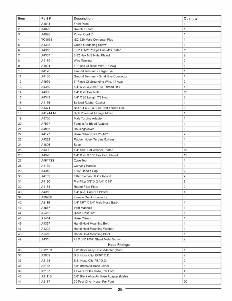
Item Part # Description Quantity1 A4814 Front Plate 1
2 A4029 Switch & Plate 1
3 A4028 Power Cord 8' 1
4 TC1038 IEC 320 Male Computer Plug 1
5 A4318 Green Grounding Screw 1
6 A4318 6-32 X 1/2" Phillips Pan M/S Plated 8
7 A4307 6-32 Hex M/S Nuts, Plated 3
8 A4179 Wire Terminal 5
9 A4991 6" Piece Of Black Wire, 14 Awg 1
10 A4178 Ground Terminal - Large Eye 1
11 A4180 Ground Terminal - Small Eye Connector 1
12 A4999 6" Piece Of Grounding Wire, 14 Awg 1
13 A4350 1/4" X 20 X 2 3/4" Full Thread Hex 4
14 A4308 1/4" X 20 Hex Nuts 19
15 A4349 1/4" X 20 Length 7/8 Hex 3
16 A4176 Spliced Rubber Gasket 1
17 A4371 Bolt 1/4 X 20 X 3 1/4 Half Thread Hex 3
18 A4860-EM High Powered 3-Stage Motor 1
19 A4756 Male Turbine Adapter 1
20 A7537 Female Air Bleed Adapter 1
21 A4815 Housing/Cover 1
22 A4177 Hose Clamp Size 28-1/2" 2
23 A4222 Rubber Hose, Turbine Exhaust 1
24 A4806 Base 1
25 A4300 1/4" SAE Flat Washer, Plated 12
26 A4320 1/4" X 20 X 1/2" Hex Bolt, Plated 12
27 A4817 Case Top 1
28 A4139 Carrying Handle 1
29 A4345 5/16" Handle Cap 2
30 A4169 Filter Element, 6 X 2 Round 2
31 A4190 Pre-Filter 3/8" X 2 1/4" X 19" 2
32 A4181 Round Filter Plate 2
33 A4310 1/4" X 20 Cap Nut Plated 4
34 A2070B Female Quick Connector 3
42 A2118 1/4" NPT X 1/4" Male Hose Barb. 1
43 A4857 Vent Manifold 1
44 A5415 Bleed Hose 12" 1
45 A5414 Hose Clamp 1
46 A4367 Handi-Hold Mounting Bolt 1
47 A4302 Handi-Hold Mounting Washer 1
48 A5416 Handi-Hold Mounting Block 1
49 A4315 #8 X 3/8" HWH Sheet Metal Screw 2
Hose Fittings35 ST2163 5/8" Black Hose Adapter (3/4" Male) 1
36 A2069 S.S. Hose Clip 15/16" O.D. 2
37 A2168 S.S. Hose Clip 7/8" O.D. 2
38 A2155 5/8" Brass Air Hose Joiner 1
39 A2157 4 Feet Of Flex Hose, Per Foot 4
40 ST2111B 5/8" Alloy Air Hose Adapter (Male) 1
41 A2167B 20 Feet Of Air Hose, Per Foot 20

26
10.3 Model 900
July 1, 2010
APOLLO SPRAYER
900
30
3231
27
28
26
12
23
2511
12
29
25
21
25
20
18
19
16 13 25
2411
12 2931
3230
22
11
14
8
9 5
24
125
2312
710
2
3
6
4
WIRING DIAGRAM
BLACK
GREEN
WH
ITE
GREEN BLACK
MOTOR
TOGGLESWITCH
POWERCORD
MODEL 900
WHITEOR BLACK
8
3334
3538
40
35 37
36
36 39
33
17
17
41
15

27
Item Part # Description Qty1 A4804 Front Plate 1
2 A4029 Switch & Plate 1
3 A4028 Power Cord 8’ 1
4 A4053 Cable Grommet 1
5 A4051 Cable Clamp 2
6 A4318 6-32 X 1/2” Phillips Pan M/S Plated 3
7 A4307 6-32 Hex M/S Nuts, Plated 3
8 A4179 Insulated Wire Terminal 2
9 A4192 Twist On Wire Connector 1
10 A4178 Ground Terminal - Large 1
11 A4350 1/4” X 20 X 2 3/4” Full Thread Hex 4
12 A4308 1/4 X 20 Hex Nuts 16
13 A4357 5/16” X 18 Nut, Plated 6
14 A4314 5/16” X 18 Nylon Locknut Plated 3
15 A4302 5/16” Washer 3
16 A4070 Spliced Rubber Gasket 1
17 A4356 Bolt 5/16” X 18 X 4 1/2 Full Thread Hex
3
18 A4162 3 Stage 7.2” Diameter Motor/Turbine 1
19 A4143 Manifold 1
20 A2103 Outlet Cap 1
21 A4815SS Housing/Cover 1
22 A4806 Base 1
23 A4300 1/4” Sae Flat Washer, Plated 12
24 A4315 #8x3/8” Hwh Sheet Metal Screw 2
25 A4320 1/4” X 20 X 1/2” Hex Bolt, Plated 13
26 A4807 Case Top 1
27 A4139 Carrying Handle 1
28 A4345 5/16” Handle Cap 2
29 A4169 Filter Element, 6x2 Round 2
30 A4190 Pre-Filter 3/8” A 2 1/4 X 19” 2
31 A4181 Round Filter Plate 2
32 A4310 1/4” X 20 Cap Nut Plated 4
33 A2070B Female Quick Connector 2
Hose Fittings34 A2163 5/8” Brass Hose Adapter (Male) 1
35 A2069 S.S. Hose Clip 15/16” O.D. 2
36 A2168 S.S. Hose Clip 7/8” O.D. 2
37 A2155 5/8” Brass Air Hose Joiner 1
38 A2155 4 Feet Of Flex Hose, Per Foot 4
39 A2110 5/8” Brass Swivel Air Hose Adapter (Female)
1
34 A2167B 30 Feet Of Air Hose, Per Foot 30
41 A2161 Male Quick Connect 1
38 A2155 4 Feet Of Flex Hose, Per Foot 4
39 A2110 5/8” Brass Swivel Air Hose Adapter (Female)
1
34 A2167B 30 Feet Of Air Hose, Per Foot 30
41 A2161 Male Quick Connect 1
Hose Fittings35 ST2163 5/8” Black Hose Adpater (3/4” Male) 1
Item Part # Description Qty36 A2069 S.S. Hose Clip 15/16” O.D. 2
37 A2168 S.S. Hose Clip 7/8” O.D. 2
38 A2155 5/8” Brass Air Hose Joiner 1
39 A2157 4 Feet Of Flex Hose, Per Foot 4
40 ST2111B 5/8” Alloy Air Hose Adapter (Male) 1
41 A2167B 20 Feet Of Air Hose, Per Foot 20

28
10.4 Model 1035July 1, 2010
APOLLO SPRAYER
1035
31
3332
28
29
27
14
25
2613
14
30
26
21
6
34
22
4223
2218
20
16
15 26
49
13
14 3032
3331
24
7
17
13
14
49
126
2514
2
5
MODEL 1035
25
8
3435
3639
41
36 38
37
37
43
44
6
45
64
77
BLACK
WIRING DIAGRAM
OR BLACKWHITE
POWERCONNECTOR
MOTOR
GREENGREEN
BLACK
TOGGLESWITCH
8
19
40
3
48
34
47
46
40073
9
8
8
12
12
10
11
8
29
Item Part # Description Quantity1 A4814 Front Plate 1
2 A4029 Switch & Plate 1
3 A4028 Power Cord 8' 1
4 TC1038 IEC 320 Male Computer Plug 1
5 A4318 Green Grounding Screw 1
6 A4318 6-32 X 1/2" Phillips Pan M/S Plated 11
7 A4307 6-32 Hex M/S Nuts, Plated 9
8 A4179 Wire Terminal 2
9 A4991 6" Piece Of Black Wire, 14 Awg 1
10 A4178 Ground Terminal - Large Eye 1
11 A4180 Ground Terminal - Small Eye Connector 1
12 A4999 6" Piece Of Grounding Wire, 14 Awg 2
13 A4350 1/4" X 20 X 2 3/4" Full Thread Hex 4
14 A4308 1/4" X 20 Hex Nuts 19
15 A4349 1/4" X 20 Length 7/8 Hex 3
16 A4176 Spliced Rubber Gasket 1
17 A4371 Bolt 1/4 X 20 X 3 1/4 Half Thread Hex 3
18 A4174-EM High Powered 4-Stage Motor 1
19 A4756 Male Turbine Adapter 1
20 A7537 Female Air Bleed Adapter 1
21 A4815 Housing/Cover 1
22 A4177 Hose Clamp Size 28-1/2" 2
23 A4222 Rubber Hose, Turbine Exhaust 1
24 A4806 Base 1
25 A4300 1/4" SAE Flat Washer, Plated 15
26 A4320 1/4" X 20 X 1/2" Hex Bolt, Plated 12
27 A4817SS Case Top 1
28 A4139 Carrying Handle 1
29 A4345 5/16" Handle Cap 2
30 A4169 Filter Element, 6 X 2 Round 2
31 A4190 Pre-Filter 3/8" X 2 1/4" X 19" 2
32 A4181 Round Filter Plate 2
33 A4310 1/4" X 20 Cap Nut Plated 4
34 A2070B Female Quick Connector 3
42 A2118 1/4" NPT X 1/4" Male Hose Barb. 1
43 A4857 Vent Manifold 1
44 A5415 Bleed Hose 12" 1
45 A5414 Hose Clamp 1
46 A4367 Handi-Hold Mounting Bolt 1
47 A4302 Handi-Hold Mounting Washer 1
48 A5416 Handi-Hold Mounting Block 1
49 A4315 #8 X 3/8" HWH Sheet Metal Screw 2
Hose Fittings35 ST2163 5/8" Black Alloy Hose Adapter (Male) 1
36 A2069 S.S. Hose Clip 15/16" O.D. 2
37 A2168 S.S. Hose Clip 7/8" O.D. 2
38 A2155 5/8" Brass Air Hose Joiner 1
39 A2157 4 Feet Of Flex Hose, Per Foot 4
40 A2111B 5/8" Black Alloy Air Hose Adapter (Male) 1
41 A2167 20 Feet Of Air Hose, Per Foot 20

30
10.5 Model 1050July 1, 2010

31
Item Part # Description Quantity1 A4814 Front Plate 1
2 A4029 Switch & Plate 1
3 A4028 Power Cord 8' 1
4 TC1038 IEC 320 Male Computer Plug 1
5 A4318 Green Grounding Screw 1
6 A4318 6-32 X 1/2" Phillips Pan M/S Plated 11
7 A4307 6-32 Hex M/S Nuts, Plated 9
8 A4179 Wire Terminal 2
9 A4991 6" Piece Of Black Wire, 14 Awg 1
10 A4178 Ground Terminal - Large Eye 1
11 A4180 Ground Terminal - Small Eye Connector 1
12 A4999 6" Piece Of Grounding Wire, 14 Awg 2
13 A4350 1/4" X 20 X 2 3/4" Full Thread Hex 4
14 A4308 1/4" X 20 Hex Nuts 19
15 A4349 1/4" X 20 Length 7/8 Hex 3
16 A4176 Spliced Rubber Gasket 1
17 A4371 Bolt 1/4 X 20 X 3 1/4 Half Thread Hex 3
18 A4858-EM 5-Stage, 5.7” Tangential Motor 1
19 A4756 Male Turbine Adapter 1
20 A7537 Female Air Bleed Adapter 1
21 A4815 Housing/Cover 1
22 A4177 Hose Clamp Size 28-1/2" 2
23 A4222 Rubber Hose, Turbine Exhaust 1
24 A4806 Base 1
25 A4300 1/4" SAE Flat Washer, Plated 15
26 A4320 1/4" X 20 X 1/2" Hex Bolt, Plated 12
27 A4817SS Case Top 1
28 A4139 Carrying Handle 1
29 A4345 5/16" Handle Cap 2
30 A4169 Filter Element, 6 X 2 Round 2
31 A4190 Pre-Filter 3/8" X 2 1/4" X 19" 2
32 A4181 Round Filter Plate 2
33 A4310 1/4" X 20 Cap Nut Plated 4
34 A2070B Female Quick Connector 3
42 A2118 1/4" NPT X 1/4" Male Hose Barb. 1
43 A4857 Vent Manifold 1
44 A5415 Bleed Hose 12" 1
45 A5414 Hose Clamp 1
46 A4367 Handi-Hold Mounting Bolt 1
47 A4302 Handi-Hold Mounting Washer 1
48 A5416 Handi-Hold Mounting Block 1
49 A4315 #8 X 3/8" HWH Sheet Metal Screw 2
Hose Fittings35 ST2163 5/8" Black Alloy Hose Adapter (Male) 1
36 A2069 S.S. Hose Clip 15/16" O.D. 2
37 A2168 S.S. Hose Clip 7/8" O.D. 2
38 A2155 5/8" Brass Air Hose Joiner 1
39 A2157 4 Feet Of Flex Hose, Per Foot 4
40 A2111B 5/8" Black Alloy Air Hose Adapter (Male) 1
41 A2167 20 Feet Of Air Hose, Per Foot 20
32
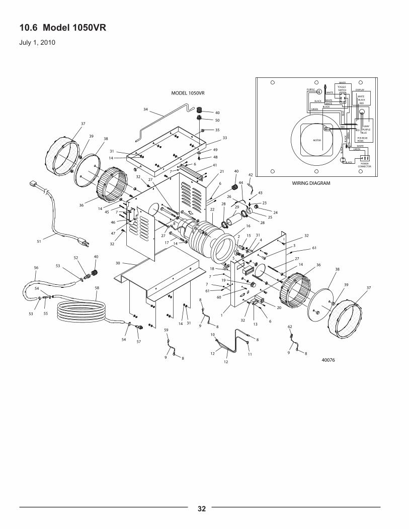
10.6 Model 1050VRJuly 1, 2010
37
3938
34
35
33
14
31
3227
1436
32
21
6
40
28
2329
2822
25
16
15 32
61
27
14 3638
3937
30
7
17
27
14
61
132
3114
2
WIRING DIAGRAM
BLACK
MOTOR
TOGGLESWITCH
POWERCONNECTOR
MODEL 1050VR
8
4052
5356
58
53 55
54
54
41
42
6
43
3
31
5
613
18
60
19
20
44
7
45 7
46
47
DISPLAY
BLACK
GREEN
PCB REARPANEL
WHITE
GRAY
PURPLEBLUE
RED
BLACK
WHITE
BLA
CK
BLA
CK
BLU
E
BLACK WHITE
WHITE
WHITE
WHITE
GRE
EN
REDRED
GREEN
PURPLE
24
451
26
57
50
40
48
49
40076
7
12
12
10
11
8
9 8
8
9 8
59
9 8
62

33
Item Part # Description Qty1 A4814 Front Plate 1
2 A4029 Switch & Plate 1
3 LEDHOLD LED Holder 1
4 160-1715-ND
LED 1
5 PM-128E LCD Display 1
6 A4318 6-32 X 1/2" Phillips Pan M/S Plated 19
7 A4307 6-32 Hex M/S Nuts, Plated 17
8 A4179 Wire Terminal 2
9 A4991 6" Piece Of Black Wire, 14 Awg 1
10 A4178 Ground Terminal - Large Eye 1
11 A4180 Ground Terminal - Small Eye Connector 1
12 A4999 6" Piece Of Grounding Wire, 14 Awg 1
13 TC1038 IEC 320 Plug 1
14 A4308 1/4" X 20 Hex Nuts 19
15 A4349 1/4" X 20 Length 7/8 Hex 3
16 A4176 Spliced Rubber Gasket 1
17 A4371 Bolt 1/4 X 20 X 3 1/4 Half Thread Hex 3
18 31CN505 Speed Control Switch 1
19 45KN017 Speed Control Knob 1
20 A4997 12amp Reset Button 1
21 A4815 Housing/Cover 1
22 A4858-EM 5-Stage, 5.7" Tangential Motor 1
23 A2118 1/4" NPT X 1/4" Male Hose Barb 1
24 A4756 Male Turbine Adapter 1
25 A7537 Female Air Bleed Adapter 1
26 A5211 Brass Air Barb 1
27 A4350 1/4" X 20 X 2 3/4" Full Thread Hex 4
28 A4177 Hose Clamp Size 28-1/2" 2
29 A4222 Rubber Hose, Turbine Exhaust 1
30 A4806 Base 1
31 A4300 1/4" SAE Flat Washer, Plated 15
32 A4320 1/4" X 20 X 1/2" Hex Bolt, Plated 12
33 A4817 Case Top 1
34 A4139 Carrying Handle 1
35 A4345 5/16" Handle Cap 2
36 A4169 Filter Element, 6 X 2 Round 2
37 A4190 Pre-Filter 3/8" X 2 1/4" X 19" 2
38 A4181 Round Filter Plate 2
39 A4310 1/4" X 20 Cap Nut Plated 4
40 A2070B Female Quick Connector 3
41 A4857 Vent Manifold 1
42 A5415 Bleed Hose 12" 1
43 A5414 Hose Clamp 1
44 A5299 Air Tube - Pressure Sensor 16" 1
45 A4379 6-32 X 3/4" Phillips Pan M/S Plated 4
46 A5299 Pcb Stand-Off Tubes 4
47 PCB-110 Pc Control Board 1
48 A4367 Handi-Hold Mounting Bolt 1
49 A4302 Handi-Hold Mounting Washer 1
50 A5416 Handi-Hold Mounting Block 1
Item Part # Description Qty51 A4028 Power Cord 8' 1
59 A4192 Crimp-On Wire Connector 1
60 A4318 Green Grounding Screw 1
61 A4315 #8 X 3/8" HWH Sheet Metal Screw 2
62 A4194 Wire Connector, Yellow 1
Hose Fittings52 ST2163 5/8" Black Alloy Hose Adapter (Male) 1
53 A2069 S.S. Hose Clip 15/16" O.D. 2
54 A2168 S.S. Hose Clip 7/8" O.D. 2
55 A2155 5/8" Brass Air Hose Joiner 1
56 A2157 4 Feet Of Flex Hose, Per Foot 4
57 A2111B 5/8" Black Alloy Air Hose Adapter (Male) 1
58 A2167 20 Feet Of Air Hose, Per Foot 20

34
10.7 Model 1100 Chassis
July 1, 2010
34
39
3233
32
34
13
11
1
2221
25
247
16
5
20
182318
15
8
23
30
29
29
33
14
31
14
8
38
19
9
13
49 42
29 6
50
2
35
17
26
41
10
12 11
43
40
28
23
46
44
47
47
43
44 45
48 46
6
37
36
35
38
23
27
16
26
2623
64 40
3
42
41
26
27
23
27

35
Item Part # Description Qty1 A4085 Chassis For Model 1100/1200 1
2 A4029 Switch & Plate 2
3 A4028 Power Cord 8' 1
4 A4195 Cable Grommet, Large 1
5 A4051 Cable Clamp 1
6 A4318 6-32 X 1/2" Phillips Pan M/S Plated 3
7 A4307 6-32 Hex M/S Nuts, Plated 11
8 A4179 Insulated Wire Terminal 4
9 A4194 Wire Connector, Yellow 2
10 A4178 Large Ring Terminal 1
11 A4180 Small Ring Terminal 1
12 A4999 6" Piece Of Green Wire, 14 Awg 1
13 A4991 6" Piece Of Black Wire, 14 Awg 1
14 A4990 Fan Cord 2
15 A4197 Outlet Plate 1
16 A4332 1/4" X 20 X 3" Hex Hd. Tap Bolt 4
17 A4336 5/8" 10-32 Phil. Head, Green 1
18 A4362 Hex Nut 10-32 Plated 2
19 A4193 Twist-On Wire Connectors, Red 1
20 A4349 1/4" X 20 Length 7/8 Hex 3
21 A4361 Threaded Rod 1/4 X 20 X 6.25" Lengths 3
22 A4309 1/4" X 20 Nylon Lock Nut Plated 3
23 A4308 1/4" X 20 Hex Nuts 25
24 A4164 2 Stage 3.2 Psi 5.7" Tangential Motor 1
25 A4102 Motor Mount Plate 1100 & 1200 Mk2 1
26 A4320 1/4" X 20 X 1/2" Hex Bolt, Plated 13
27 A4300 1/4" SAE Flat Washer, Plated 14
28 A4989 Manifold For 1100 & 1200 1
29 A4177 Hose Clamp Size 28-1/2" 3
30 A4250 Rubber Hose, Thin Wall 2" Dia 3" Piece 1
31 A4162 Ametek Turbine Motor 6.0 Psi 1
32 A4090 Motor Support Tube 4.5" X .05/Ft. 3
33 A4105 Transition Tube Gasket 2
34 A4325 5/16" X 18 X 5.5" Tap Bolt Plated 3
35 A4302 5/16" SAE F/W Plated Washer 5
36 A4314 5/16" X 18 Nylon Lock Nut Plated 3
37 A4173 Swivel Wheel/Castor 1
38 A4358 Nut 1/2 X 13 Hex Plated 2
39 A4070 Spliced Rubber Spacing Gasket 1 X .5 X 5.75
1
40 A4305 1/2" SAE F/W Plated Washer 6
41 A4045 Wheel, 8" Ball Bearing/ Rubber Tire 2
42 A4360 Bolt 1/2 X 13 X 2" Half Thread Hex. Plated 2
43 A4098 6" X 4" 1 1/2" Rectangle Paper Filter 4
44 A4094 6" X 4" Rectangular Filter Plate 4
45 A4310 1/4" X 20 Cap Nut Plated 8
46 A4190 Char-Ether Pre-Filter 3/8" X 2 1/4" X 19" 4
47 A2103 Brass Air Cap, New Style 2
48 A2070 Brass Quick Connect (Female) 2
49 A4322 3/8" X 16 X 2" Full Thread Plated Hex Bolt 2
50 A4313 3/8" X 16 Plated Nut 2
Item Part # Description Qty51 A4088 Cover For Model 1100/1200 1
52 A4103 Fan 2
53 A4317 6-32 X 1/2" Counter Sunk Head 8
54 A4333 1/4" X 20 X 4" Full Thread Bolt 2
55 A4097 9" X 3" Round Paper Element 1
56 A4196 9" Round Filter Plate 1
57 A4095 Char-Ether Pre-Filter 3/8" X 3 1/4" X 26" 1
58 A4006 Handle (Chrome) 1
59 A4042 Handle Grip (Plastic) 2
Hose Fittings60 A2163 5/8" Brass Hose Adapter (Male) 1
61 A2168 S.S. Hose Clip 7/8" O.D. 2
62 A2157 4 Feet Of Flex Hose, Per Foot 4
63 A2155 5/8" Brass Air Hose Joiner 1
64 A2069 S.S. Hose Clip 15/16" O.D. 2
65 A2167 40 Feet Of Air Hose, Per Foot 40
66 A2110 5/8" Brass Swivel Air Hose Adapter (Female) 1
67 A2111 Male Quick Connect 1

36
10.8 Model 1100 TopJuly 1, 2010
61 63
64
62 61
60
65
48
64 6667
WIRING DIAGRAM
BLACK
GREEN
MOTOR 2
TOGGLESWITCHES
POWERCORD
GRE
EN/Y
ELLO
W (G
RO
UN
D)
CLAMPCABLE
MOTOR 1
BLACK
BLACK
BLACK
FANS
BLACKBLACK
BLACK
BLACK
BLACK
BLA
CK
WHITE
BLACK
GREEN
WHITE
MODEL 1100
51
7
52
53
43
44
27
54
59
26
57
46
45
2355
28
23
45
56
58
59
2723
16
68
48
69
70

37
Item Part # Description Qty1 A4085 Chassis For Model 1100/1200 1
2 A4029 Switch & Plate 2
3 A4028 Power Cord 8' 1
4 A4195 Cable Grommet, Large 1
5 A4051 Cable Clamp 1
6 A4318 6-32 X 1/2" Phillips Pan M/S Plated 3
7 A4307 6-32 Hex M/S Nuts, Plated 11
8 A4179 Insulated Wire Terminal 4
9 A4194 Wire Connector, Yellow 2
10 A4178 Large Ring Terminal 1
11 A4180 Small Ring Terminal 1
12 A4999 6" Piece Of Green Wire, 14 Awg 1
13 A4991 6" Piece Of Black Wire, 14 Awg 1
14 A4990 Fan Cord 2
15 A4197 Outlet Plate 1
16 A4332 1/4" X 20 X 3" Hex Hd. Tap Bolt 4
17 A4336 5/8" 10-32 Phil. Head, Green 1
18 A4362 Hex Nut 10-32 Plated 2
19 A4193 Twist-On Wire Connectors, Red 1
20 A4349 1/4" X 20 Length 7/8 Hex 3
21 A4361 Threaded Rod 1/4 X 20 X 6.25" Lengths 3
22 A4309 1/4" X 20 Nylon Lock Nut Plated 3
23 A4308 1/4" X 20 Hex Nuts 25
24 A4164 2 Stage 3.2 Psi 5.7" Tangential Motor 1
25 A4102 Motor Mount Plate 1100 & 1200 Mk2 1
26 A4320 1/4" X 20 X 1/2" Hex Bolt, Plated 13
27 A4300 1/4" SAE Flat Washer, Plated 14
28 A4989 Manifold For 1100 & 1200 1
29 A4177 Hose Clamp Size 28-1/2" 3
30 A4250 Rubber Hose, Thin Wall 2" Dia 3" Piece 1
31 A4162 Ametek Turbine Motor 6.0 Psi 1
32 A4090 Motor Support Tube 4.5" X .05/Ft. 3
33 A4105 Transition Tube Gasket 2
34 A4325 5/16" X 18 X 5.5" Tap Bolt Plated 3
35 A4302 5/16" SAE F/W Plated Washer 5
36 A4314 5/16" X 18 Nylon Lock Nut Plated 3
37 A4173 Swivel Wheel/Castor 1
38 A4358 Nut 1/2 X 13 Hex Plated 2
39 A4070 Spliced Rubber Spacing Gasket 1 X .5 X 5.75
1
40 A4305 1/2" SAE F/W Plated Washer 6
41 A4045 Wheel, 8" Ball Bearing/ Rubber Tire 2
42 A4360 Bolt 1/2 X 13 X 2" Half Thread Hex. Plated 2
43 A4098 6" X 4" 1 1/2" Rectangle Paper Filter 4
44 A4094 6" X 4" Rectangular Filter Plate 4
45 A4310 1/4" X 20 Cap Nut Plated 8
46 A4190 Char-Ether Pre-Filter 3/8" X 2 1/4" X 19" 4
47 A2103 Brass Air Cap, New Style 2
48 A2070 Brass Quick Connect (Female) 2
49 A4322 3/8" X 16 X 2" Full Thread Plated Hex Bolt 2
50 A4313 3/8" X 16 Plated Nut 2
Item Part # Description Qty51 A4088 Cover For Model 1100/1200 1
52 A4103 Fan 2
53 A4317 6-32 X 1/2" Counter Sunk Head 8
54 A4333 1/4" X 20 X 4" Full Thread Bolt 2
55 A4097 9" X 3" Round Paper Element 1
56 A4196 9" Round Filter Plate 1
57 A4095 Char-Ether Pre-Filter 3/8" X 3 1/4" X 26" 1
58 A4006 Handle (Chrome) 1
59 A4042 Handle Grip (Plastic) 2
Hose Fittings60 A2163 5/8" Brass Hose Adapter (Male) 1
61 A2168 S.S. Hose Clip 7/8" O.D. 2
62 A2157 4 Feet Of Flex Hose, Per Foot 4
63 A2155 5/8" Brass Air Hose Joiner 1
64 A2069 S.S. Hose Clip 15/16" O.D. 2
65 A2167 40 Feet Of Air Hose, Per Foot 40
66 A2110 5/8" Brass Swivel Air Hose Adapter (Female) 1
67 A2111 Male Quick Connect 1

38
10.9 Model 1200 ChassisJuly 1, 2010
25
40
21
1
46
22
24
2
4
45
47
44
17 24
6
6
5
19
18
27
17
26
30
31
30
32
34
33
33
35
35
44
45
24
41
38
39
11
6
7
12
14
9
13
4743
43
41
3
5051 36
27
24
28
24
39
16
49
48
4829
27
42
42
23
34
37
36
24
10
11
11
12 11
14 88
14 1120
8
11
19
30
15
15
28
13

39
Item Part # Description Qty
1 A4085 Chassis For Model 1100/1200 1
2 A4029 Switch & Plate 3
3 A4028 Power Cord 8' 1
4 A4195 Cable Grommet, Large 1
5 A4051 Cable Clamp 1
6 A4318 6-32 X 1/2" Phillips Pan M/S Plated 3
7 A4307 6-32 Hex M/S Nuts, Plated 9
8 A4179 Wire Terminal 6
9 A4194 Wire Connector, Yellow 2
10 A4178 Ground Terminal - Large Eye 1
11 A4180 Ground Terminal - Small Eye Connector 6
12 A4999 6" Piece Of Grounding Wire, 14 Awg 2
13 A4992 6" Piece Of White Copper Wire, 14 Awg 1
14 A4991 6" Piece Of Black Copper Wire, 14 Awg 1
15 A4990 Fan Cord 2
16 A4197 Grounding Outlet 15amp-125 Volt 1
17 A4332 1/4" X 20 X 3" Hex Hd. Tap Bolt 4
18 A4336 5/8" 10-32 Phil. Head, Green 1
19 A4362 Hex Nut 10-32 Plated 2
20 A4193 Twist-On Wire Connectors, Red 1
21 A4349 1/4" X 20 Length 7/8 Hex 3
22 A4361 Threaded Rod 1/4 X 20 X 6.25" Lengths 3
23 A4309 1/4" X 20 Nylon Lock Nut Plated 3
24 A4308 1/4" X 20 Hex Nuts 23
25 A4164 2 Stage 3.2 Psi 5.7" Tangential Motor 1
26 A4102 Motor Mount Plate 1100 & 1200 Mk2 1
27 A4320 1/4" X 20 X 1/2" Hex Bolt, Plated 16
28 A4300 1/4" SAE Flat Washer, Plated 11
29 A4989 Manifold For 1100 & 1200 1
30 A4177 Hose Clamp Size 28-1/2" 3
31 A4250 Rubber Hose, Thin Wall 2" Dia 3" Piece 1
32 A4162 Ametek Turbine Motor 6.0 Psi 1
33 A4090 Motor Support Tube 4.5" X .05/Ft. 3
34 A4105 Transition Tube Gasket 2
35 A4325 5/16" X 18 X 5.5" Tap Bolt Plated 3
36 A4302 5/16" SAE F/W Plated Washer 5
37 A4314 5/16" X 18 Nylon Lock Nut Plated 3
38 A4173 Swivel Wheel/Castor 1
39 A4358 Nut 1/2 X 13 Hex Plated 2
40 A4070 Spliced Rubber Spacing Gasket 1 X .5 X 5.75 1
41 A4305 1/2" SAE F/W Plated Washer 6
42 A4045 Wheel, 8" Ball Bearing/ Rubber Tire 2
43 A4360 Bolt 1/2 X 13 X 2" Half Thread Hex. Plated 2
44 A4098 6" X 4" 1 1/2" Rectangle Paper Filter 4
45 A4094 6" X 4" Rectangular Filter Plate 4
46 A4310 1/4" X 20 Cap Nut Plated 8
47 A4190 Char-Ether Pre-Filter 3/8" X 2 1/4" X 19" 4
48 A2103 Brass Air Cap, New Style 2
49 A2070 Brass Quick Connect (Female) 2
50 A4322 3/8" X 16 X 2" Full Thread Plated Hex Bolt 2
Item Part # Description Qty
51 A4313 3/8" X 16 Plated Nut 2
52 A4088 Cover For Model 1100/1200 1
53 A4103 Fan 2
54 A4317 6-32 X 1/2" Counter Sunk Head 8
55 A4333 1/4" X 20 X 4" Full Thread Bolt 2
56 A4097 9" X 3" Round Paper Element 1
57 A4196 9" Round Filter Plate 1
58 A4095 Char-Ether Pre-Filter 3/8" X 3 1/4" X 26" 1
59 A4006 Handle (Chrome) 1
60 A4042 Handle Grip (Plastic) 2
61 A4112 Fluid Feed System 1
62 A4101 Pressure Pot Platform 1
63 A4015 2.5 Gallon Pressure Pot 1
Air Hose Fittings64 A2163 5/8" Brass Hose Adapter (Male) 1
65 A2168 S.S. Hose Clip 7/8" O.D. 2
66 A2157 4 Feet Of Flex Hose, Per Foot 4
67 A2155 5/8" Brass Air Hose Joiner 1
68 A2069 S.S. Hose Clip 15/16" O.D. 2
69 A2167 40 Feet Of Air Hose, Per Foot 30
70 A2110 5/8" Brass Swivel Air Hose Adapter (Female) 1
71 A2111 Male Quick Connect 1
Fluid Hose Fittings72 A2064 1/4" Fluid Connector 2
73 A2117 1/4" Lined Fluid Hose, Per Foot 40

40
10.10 Model 1200 TopJuly 1, 2010
46
45
52
24
44
WIRING DIAGRAM
BLACK
GREEN
MOTOR 1
TOGGLESWITCHES
POWERCORD
1200 Model Air Hose
65 67
68
66 65
64
69
49
68 7071
47
GRE
EN/Y
ELLO
W (G
RO
UN
D)
CLAMPCABLE
60
60
59
MOTOR 2
BLACKBLACK
BLACK
BLACK
ACRECEPT.
FANS
BLACKBLACK
BLACK
BLACK
BLACK
BLA
CK
WHITE
BLACKBLACK
GREEN
BLACK
WHITE
GREEN
62
63
61
53
7
54
55
28
56
57
46
58
24
28
27
17
72
72
73
48
74
76
75
1200 Model Fluid Hose

41
Item Part # Description Qty
1 A4085 Chassis For Model 1100/1200 1
2 A4029 Switch & Plate 3
3 A4028 Power Cord 8' 1
4 A4195 Cable Grommet, Large 1
5 A4051 Cable Clamp 1
6 A4318 6-32 X 1/2" Phillips Pan M/S Plated 3
7 A4307 6-32 Hex M/S Nuts, Plated 9
8 A4179 Wire Terminal 6
9 A4194 Wire Connector, Yellow 2
10 A4178 Ground Terminal - Large Eye 1
11 A4180 Ground Terminal - Small Eye Connector 6
12 A4999 6" Piece Of Grounding Wire, 14 Awg 2
13 A4992 6" Piece Of White Copper Wire, 14 Awg 1
14 A4991 6" Piece Of Black Copper Wire, 14 Awg 1
15 A4990 Fan Cord 2
16 A4197 Grounding Outlet 15amp-125 Volt 1
17 A4332 1/4" X 20 X 3" Hex Hd. Tap Bolt 4
18 A4336 5/8" 10-32 Phil. Head, Green 1
19 A4362 Hex Nut 10-32 Plated 2
20 A4193 Twist-On Wire Connectors, Red 1
21 A4349 1/4" X 20 Length 7/8 Hex 3
22 A4361 Threaded Rod 1/4 X 20 X 6.25" Lengths 3
23 A4309 1/4" X 20 Nylon Lock Nut Plated 3
24 A4308 1/4" X 20 Hex Nuts 23
25 A4164 2 Stage 3.2 Psi 5.7" Tangential Motor 1
26 A4102 Motor Mount Plate 1100 & 1200 Mk2 1
27 A4320 1/4" X 20 X 1/2" Hex Bolt, Plated 16
28 A4300 1/4" SAE Flat Washer, Plated 11
29 A4989 Manifold For 1100 & 1200 1
30 A4177 Hose Clamp Size 28-1/2" 3
31 A4250 Rubber Hose, Thin Wall 2" Dia 3" Piece 1
32 A4162 Ametek Turbine Motor 6.0 Psi 1
33 A4090 Motor Support Tube 4.5" X .05/Ft. 3
34 A4105 Transition Tube Gasket 2
35 A4325 5/16" X 18 X 5.5" Tap Bolt Plated 3
36 A4302 5/16" SAE F/W Plated Washer 5
37 A4314 5/16" X 18 Nylon Lock Nut Plated 3
38 A4173 Swivel Wheel/Castor 1
39 A4358 Nut 1/2 X 13 Hex Plated 2
40 A4070 Spliced Rubber Spacing Gasket 1 X .5 X 5.75 1
41 A4305 1/2" SAE F/W Plated Washer 6
42 A4045 Wheel, 8" Ball Bearing/ Rubber Tire 2
43 A4360 Bolt 1/2 X 13 X 2" Half Thread Hex. Plated 2
44 A4098 6" X 4" 1 1/2" Rectangle Paper Filter 4
45 A4094 6" X 4" Rectangular Filter Plate 4
46 A4310 1/4" X 20 Cap Nut Plated 8
47 A4190 Char-Ether Pre-Filter 3/8" X 2 1/4" X 19" 4
48 A2103 Brass Air Cap, New Style 2
49 A2070 Brass Quick Connect (Female) 2
50 A4322 3/8" X 16 X 2" Full Thread Plated Hex Bolt 2
Item Part # Description Qty
51 A4313 3/8" X 16 Plated Nut 2
52 A4088 Cover For Model 1100/1200 1
53 A4103 Fan 2
54 A4317 6-32 X 1/2" Counter Sunk Head 8
55 A4333 1/4" X 20 X 4" Full Thread Bolt 2
56 A4097 9" X 3" Round Paper Element 1
57 A4196 9" Round Filter Plate 1
58 A4095 Char-Ether Pre-Filter 3/8" X 3 1/4" X 26" 1
59 A4006 Handle (Chrome) 1
60 A4042 Handle Grip (Plastic) 2
61 A4112 Fluid Feed System 1
62 A4101 Pressure Pot Platform 1
63 A4015 2.5 Gallon Pressure Pot 1
Air Hose Fittings64 A2163 5/8" Brass Hose Adapter (Male) 1
65 A2168 S.S. Hose Clip 7/8" O.D. 2
66 A2157 4 Feet Of Flex Hose, Per Foot 4
67 A2155 5/8" Brass Air Hose Joiner 1
68 A2069 S.S. Hose Clip 15/16" O.D. 2
69 A2167 40 Feet Of Air Hose, Per Foot 30
70 A2110 5/8" Brass Swivel Air Hose Adapter (Female) 1
71 A2111 Male Quick Connect 1
Fluid Hose Fittings72 A2064 1/4" Fluid Connector 2
73 A2117 1/4" Lined Fluid Hose, Per Foot 40
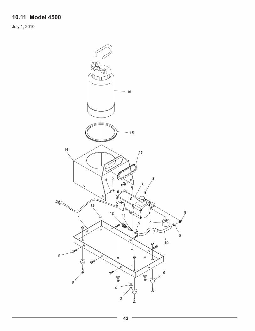
42
10.11 Model 4500July 1, 2010

43
Diagram # Part # Description Quantity1 A4501 Compressor Deck 1
2 A4198 110v Mini Compressor Unit 1
3 A4320 1/4" X 20 X 1/2" Hex Bolt Plated .5. 12
4 A4300 1/4" SAE F/W Plated Washer 16
5 A4308 1/4" X 20 Hex Nuts Plated 4
6 A9016 Rubber Foot 4
7 A4998 Pressure Regulator 1
8 A4503 1/8" Male NPT X 1/4" Male Hose Barb 90° 1
9 A4033 Air Line Hose Clip S.S. 2
10 A2116 1/4" Air Hose, Per Foot 3
11 A2119 1/4" X 1/4" Female Swivel Barb 1
12 A4026 Quick Connect Female With 1/4" Male Thread 1
13 A4310 1/4" X 20 Cap Nut Plated 8
14 A4502 Pressure Pot Support Bracket 1
15 A4613 Rubber Edge Trim 2
16 A4200 2 Quart Pressure Pot W/Single Regulator 1

44
10.12 Model 4550
July 1, 2010
WIRING DIAGRAM
POWER
CORDCLAMP
CABLE BLACK
ACRECEPT.
GREEN
WHITE
30
5
MODEL 4550
4
3
1
5
4
27
26
25
21
21
14
13
1516
15
1718
10
11
3
2 6
6
8
8
9
12
32
32
31
9
9
9
2322
21
11
10
19
10
11
19
29
7
24
CABLECLAMP
COMPRESSOR
GREEN
WHITE
BLACK
11
10
1923
22
28
20
21

45
Diagram # Part # Description Quantity1 A4554 Cart Base Plate Paint Blue 1
2 A4555 Cart Axle (Zinc Plated 1
3 A4556 Wheel Spacer (6061 Alu.) 2
4 A4558 10" X 1 3/4" Wheel 2
5 A4374 1/2" Axle Cap 2
6 A4551 Frame Tube (Chrome) 2
7 A4559 Rubber Tip For Frame Tube 2
8 A4560 Handle Button 2
9 A4364 1/4" X 20 X 1 1/4" Hex Bolt Plated .5. 4
10 A4300 1/4" SAE F/W Plated Washer 20
11 A4308 1/4" X 20 Hex Nuts Plated 20
12 A4198 110v Mini Compressor Unit 1
13 A4998 Pressure Regulator 1
14 A4503 1/8" Male NPT X 1/4" Male Hose Barb 90° 1
15 A4033 Air Hose Clip S.S. 2
16 A2116 1/4" Air Hose, Per Foot 3
17 A2119 1/4" X 1/4" Female Swivel Barb 1
18 A4026 Quick Connect Female With 1/4" Male Thread 1
19 A4320 1/4" X 20 X 1/2" Hex Bolt Plated .5. 16
20 A4553 Pressure Pot Deck 1
21 A4318 6-32 X 1/2" Phillips Pan M/S Plated 4
22 A4307 6-32 Hex M/S Nuts Plated 2
23 A4051 Cable Clamps, Black 2
24 A4557 Outlet Box (Plastic) 1
25 A4197 Outlet 15 amp-125 Volt 1
26 A4053 Flexible Cord Protector 1
27 A4028 8 Foot Power Cord 1
28 A4178 Large Ring Terminal 3
29 A4552 Support Ring For Pressure Pot. 2
30 A4900 2.5 Gallon Pressure Pot 1
31 A4006 Handle (Chrome) 1
32 A4042 Handle Grip 2

46
11. Genuine Apollo Accessories
Designed to be used with Apollo turbine systems: Models 835, 900, 1035, 1050, 1050VR and 1100.
Excellent in the shop or on site. Perfect for that larger job when a quart (litre) is just not enough or when greater spray gun mobility is needed to get into a tight corner.
Includes: oil-less mini air compressor, 2 quart (2 litre) non-stick coated pressure pot with stainless steel material tube, 20’ (6m) or 30’ (9m) fluid hose, air blanking screw and 4 wheels for easy mobility.Order part #A4500.
Designed to be used with Apollo turbine systems: Models 835, 900, 1035, 1050 and 1050VR.
Excellent in the shop or on site. Perfect for larger jobs when a quart (litre) is just not enough or when greater spray gun mobility is needed to get into a tight corner. 2.5 gallon (10 litre) pressure pot, non-stick coated inside and out, with stainless steel fluid parts throughout. Large wheels provide easier mobility when going up and down stairs or curbs.
Includes: 2.5 gallon (10 litre) deluxe pressure pot, oil-less mini air compressor, 20’ (6m) or 30’ (9m) fluid hose, air blanking screw and cart.Order part #A4550.
4500–2 Quart (2 Litre)Fluid Feed System #A4500
4550 –Mobile Cart andFluid Feed System #A4550

47
Using genuine Apollo accessories is important to the longevity, ergonomics and portability of your equipment. Other brands of accessories are not designed specifically with your Apollo brand equipment in mind and could cause abnormal functionality. For a complete list of Genuine Apollo parts please visit our website at www.hvlp.com or call a sales associate at 888-900-4857.
Turbine “Y” Connector #A4227 Handi-Hold™ Spray Gun Docking Station #A5326
Fluid Hoses Turbine Air Hoses A2113 - 6’ (2m) x 1/4” (6mm) fluid hose with couplers A1068 - 24’ (7m) x 5/8” (16mm) flex-air hose A2059 - 20’ (6m) x 1/4” (6mm) fluid hose with couplers A1069 - 34’ (10m) x 5/8” (16mm) flex-air hose A2060 - 40’ (12m) x 1/4” (6mm) fluid hose with couplers A1070 - 44’ (13m) x 5/8” (16mm) flex-air hose A2114 - 6’ (2m) x 3/8” (10mm) fluid hose with couplers A2159 - 20’ (6m) x 3/8” (10mm) fluid hose with couplers A2160 - 40’ (12m) x 3/8” (10mm) fluid hose with couplers
A9012 - 800S Filter Replacement. FS1900 - Deluxe Cleaning Kit, Life Time Warranty.
Pre- FiltersReplacement Filters
Model 725 #A4129800S #A9012835/900/1035/1050VR #A41711100/1200 #A4153
Model 725 #A4058800S None835/900/1035/1050VR #A40961100/1200 2x #A4096 1x#A4096

48
FS 1670 - Filter Stand, Fits 1 & 2 Quart (1 & 2 Litre) Cups. A5251 - 1 Quart (1 Litre) Cup Assembly
A5269 - 8oz (250ml) Cup Assembly A5233, A5034 & A7536 - Gravity Feed Cup Assemblies 250cc, 600cc 1000cc.
49
12. WarrantyTwo Year Limited WarrantyThe machine and Equipment is WARRANTED by APOLLO SPRAYERS INTERNATIONAL, INC. for a total period of TWO YEARS on a PRO-RATED Basis (see Schedule below), from the ORIGINAL date of purchase by the ORIGINAL PURCHASER. Proof of purchase to be included and all SHIPPING CHARGES to be pre-paid.
APOLLO SPRAYERS INTERNATIONAL INC., upon examination of the machine/equipment will replace or repair at their discretion any defects in material or workmanship.
Warranty ScheduleTimeframe Parts Labor
First 6 months No Charge No ChargeSecond 6 months No Charge No Charge
Third 6 months 50% of List ChargedFinal 6 months 75% of List Charged
Labor will be charged at the current hourly rate, or specified job rate.
This WARRANTY does NOT include: misuse, damage, neglect, alterations, disassembled equipment or modifications, lack of maintenance, cleaning, water damage to electrical parts, INCORRECT VOLTAGE CONNECTION.
This Warranty is in lieu of all other express warranties, any WARRANTY implied by law, including but not limited to, implied Warranties of merchantability or fitness, is excluded to the maximum extent permitted by law and, if not excludable, is limited to the duration of the express Warranty.
No representative or person is authorized to extend this Warranty or to create for APOLLO SPRAYERS INTERNATIONAL, INC. any other liability in connection with the sale of any APOLLO SPRAYERS product. APOLLO SPRAYERS INTERNATIONAL, INC. shall not be liable for any consequential, incidental or special damages of any kind directly or indirectly resulting from breach of any express or implied warranty.
Some states do allow the exclusion or limitation of incidental or consequential damages or limitations on the length of any Warranty so that the above limitations and exclusions may not apply to you: however, to the maximum extent permitted under applicable law, the only rights and remedies shall be to obtain a replacement for any defective product.
This Warranty gives you specific legal rights and you may also have other rights which vary from State to State.

50
Apollo Sprayers International, Inc. 1030 Joshua Way, Vista, CA 92081 Parts & Service: (760) 727-8300 Fax: (760) 727-9325 Toll Free Sales: (888) 900-HVLP (4857) www.hvlp.com