APN-2320 General Handling and ... - download.luminus.com · 3 APN-002320 Rev 02 © 2015 Luminus...
10
1 APN-002320 Rev 02 © 2015 Luminus Devices, Inc. - All Rights Reserved Luminus Devices, Inc. • T 978.528.8000 • www.luminus.com 175 New Boston St • Woburn, MA 01801 1.0 Introduction This document contains general guidelines for handling, storing, soldering, and assembly of Luminus COB arrays. The devices are robust and do not require extreme protective measures in handling or assembly. However there are a number of practices that should be followed to avoid inadvertent damage to the device. Failure to follow these practices can result in the destruction of the device as well as latent damage which may drastically shorten the life of the LED array. General Handling and Soldering Notes for Luminus COB Arrays Application Note Table of Contents 1.0 Introduction .......................... 1 2.0 General Handling ..................... 1 2.1 Chemical compatibility ................. 2 2.2 ESD Protection ......................... 3 3.0 Soldering to Luminus COBs ............ 3 4.0 Thermal Interface and Heat Sinking .... 5 5.0 Mounting the Device .................. 6 5.1 Solderless Connectors .................. 7 6.0 Reflectors and Secondary Optics ....... 8 7.0 Design Files ........................... 9 8.0 Failure Modes ....................... 10 2.0 General Handling • Devices should be lifted or carried with tweezers on two adjacent corners. Tweezers should be rounded and free of sharp edges. Avoid contacting the solder pads, yellow resin light emitting surface (LES) area or surround- ing retaining ring (See Figures 2-5.) • The yellow resin LES area is slightly sticky and may attract dirt, fibers or other particles. If a particle becomes stuck to the LES the potential exists for the particle to heat up in operation and damage the device. If a particle be- comes stuck to the yellow resin material it can be removed using a small amount of isopropyl alcohol and the gentle application of a cotton swab. • Do not store or stack anything on top of Luminus COB arrays unless they are secure in their packaging. Small amounts of pressure on the yellow resin LES area can cause permanent damage to the device. • Luminus COBs may be lifted, placed or carried by hand provided all handling guidelines are observed. Assemblers handling the devices should wear finger cots or latex gloves to minimize risk of damage. Fig.1 Luminus COB
Transcript of APN-2320 General Handling and ... - download.luminus.com · 3 APN-002320 Rev 02 © 2015 Luminus...

1APN-002320 Rev 02 © 2015 Luminus Devices, Inc. - All Rights Reserved
Luminus Devices, Inc. • T 978.528.8000 • www.luminus.com175 New Boston St • Woburn, MA 01801
1.0 Introduction
This document contains general guidelines for handling, storing, soldering, and assembly of Luminus COB arrays. The devices are robust and do not require extreme protective measures in handling or assembly. However there are a number of practices that should be followed to avoid inadvertent damage to the device. Failure to follow these practices can result in the destruction of the device as well as latent damage which may drastically shorten the life of the LED array.
General Handling and Soldering Notes for Luminus COB
Arrays
Application Note
Table of Contents1.0 Introduction . . . . . . . . . . . . . . . . . . . . . . . . . .1
2.0 General Handling . . . . . . . . . . . . . . . . . . . . .1 2.1 Chemical compatibility . . . . . . . . . . . . . . . . .2 2.2 ESD Protection . . . . . . . . . . . . . . . . . . . . . . . . .33.0 Soldering to Luminus COBs . . . . . . . . . . . .3
4.0 Thermal Interface and Heat Sinking . . . .55.0 Mounting the Device . . . . . . . . . . . . . . . . . .6
5.1 Solderless Connectors . . . . . . . . . . . . . . . . . .7
6.0 Reflectors and Secondary Optics . . . . . . .8
7.0 Design Files . . . . . . . . . . . . . . . . . . . . . . . . . . .9
8.0 Failure Modes . . . . . . . . . . . . . . . . . . . . . . . 10
2.0 General Handling
• Devices should be lifted or carried with tweezers on two adjacent corners. Tweezers should be rounded and free of sharp edges. Avoid contacting the solder pads, yellow resin light emitting surface (LES) area or surround-ing retaining ring (See Figures 2-5.)
• The yellow resin LES area is slightly sticky and may attract dirt, fibers or other particles. If a particle becomes stuck to the LES the potential exists for the particle to heat up in operation and damage the device. If a particle be-comes stuck to the yellow resin material it can be removed using a small amount of isopropyl alcohol and the gentle application of a cotton swab.
• Do not store or stack anything on top of Luminus COB arrays unless they are secure in their packaging. Small amounts of pressure on the yellow resin LES area can cause permanent damage to the device.
• Luminus COBs may be lifted, placed or carried by hand provided all handling guidelines are observed. Assemblers handling the devices should wear finger cots or latex gloves to minimize risk of damage.
Fig.1 Luminus COB

2APN-002320 Rev 02 © 2015 Luminus Devices, Inc. - All Rights Reserved
Luminus Devices, Inc. • T 978.528.8000 • www.luminus.com175 New Boston St • Woburn, MA 01801
Handling and Soldering of COBs
Fig.2 Correct Handling Fig.3 Correct Handling
Fig.4 Incorrect Handling Fig.5 Incorrect Handling
2.1 Chemical Compatibility
Certain common chemicals can cause damage to COB devices if they come into contact or in some cases are stored or placed nearby. For example the yellow resin material can act as a getter and absorb hydrocarbons from the environment which degrades the performance and longevity of the device. Below is a partial list of chemicals which can potentially cause damage to Luminus COB arrays.

3APN-002320 Rev 02 © 2015 Luminus Devices, Inc. - All Rights Reserved
Luminus Devices, Inc. • T 978.528.8000 • www.luminus.com175 New Boston St • Woburn, MA 01801
Handling and Soldering of COBs
2.2 Electrostatic Discharge (ESD) Protection
Luminus COBs can suffer extensive and permanent damage due to electrostatic discharge (ESD) that could potentially occur as a result of shipping, handling, and assembly. The following ESD protection guidelines should be used at all times when working with Luminus COBs.
• Storage: Products should be stored in their containers placed inside closed ESD shielding bags. • Assembly: Individuals handling COBs for the purposes of assembly should be trained in ESD protection practices.
Assemblers should maintain constant conductive contact with a path to ground by means of a wrist strap, ankle straps, mat or other ESD protection system.
• Transporting: When transporting the devices from one assembly area to another, ESD shielded carts and carriers should be used.
3.0 Soldering to Luminus COBs
Electrically conductive pads are provided on the core board of CXM devices for the purpose of soldering wire leads. Table 2 below details the compatible wire gauge for each size core board. A hot soldering iron can cause permanent damage and catastrophic failure. The devices may be soldered by hand or by use of a reflow oven. Luminus recommends the use of a solder stencil in order to prevent solder from contacting areas of the device other than the solder pads.
Table 1 Common Chemicals Know To Adversely Affect Luminus Devices
Acetates Ketones
Acetic acid Liquid hydrocarbons
Acrylates Phosphoric acid
Aldehydes Potassium hydroxide
Aldehydes Siloxanes, fatty acids
Amines Sodium Hydroxide
Benzene Sulfur compounds
Cl, F,or Br containing compounds Sulfuric Acid
Dienes Toluene
Ethers Xylenes
Hydrochloric Acid Nitric Acid

4APN-002320 Rev 02 © 2015 Luminus Devices, Inc. - All Rights Reserved
Luminus Devices, Inc. • T 978.528.8000 • www.luminus.com175 New Boston St • Woburn, MA 01801
Handling and Soldering of COBs
Solder Shielding
• Do not allow any solder to contact the yellow light emitting surface or surrounding retaining ring as this can seriously damage or destroy the device. For hand soldering a solder shield may be used to protect the sensitive areas of the COB. An example of a solder shield design for the CXM-7 is shown below in figure 6.
Additional Notes
• Do not attach COB to heat sink prior to soldering
• ESD protection is required when soldering or handling COBs
• Avoid contacting yellow light emitting surface of COB
3.0 Soldering to Luminus COBs Cont.
Wire Conection
1. Place device on hotplate at 150oC
2. Use a soldering iron set at 300oC
3. Tin the pads with SAC305 flux-core solder wire
4. Strip and tin 22 or 24 AWG wire with SAC305 flux-core solder wire
5. Solder wire to pad while keeping the device on the 150oC hotplate
6. Remove the soldering iron from the device, then let the device sit for several seconds
7. Lift the device off of the hotplate and place it on a surface to cool
Solder Shield Dimensions
Figure 6 depicts a potential design solution for a solder shield for CXM-7 devices. While other designs may be more suitable for various applications and assembly environments, this rendering illustrates the two critical aspects for solder shielding. The first be-ing that the solder shield protects both the LES and retaining ring from inadvertent contact with a hot soldering iron. The second critical aspect is that the contact pads are unobscured by the solder shield. For additional support in designing a solder shield for assembly stations contact [email protected]
Fig. 6 Solder Shield Design

5APN-002320 Rev 02 © 2015 Luminus Devices, Inc. - All Rights Reserved
Luminus Devices, Inc. • T 978.528.8000 • www.luminus.com175 New Boston St • Woburn, MA 01801
Handling and Soldering of COBs
4.0 Thermal Interface and Heatsinking
• The aluminum core board of Luminus COB arrays is not by itself sufficient for heat sinking the device. Luminus COB arrays should always be operated in conjunction with a means of dissapating enough heat energy so that the device remains within the recommended junction temeratures and operating temperature.
• A thermal interface material (TIM) should be used at all times in conjunction with the heat sink and Luminus de-vice. The TIM should maintain continuous contact with the entire back portion of the Al core board and should likewise be in continuous contact with the heat sink. For a list of compatible TIMs see APN-002319 Design Guide-lines and Ecosystems for Luminus COB Arrays.
• Thermal grease should be applied to the heat sink first and then the COB should be placed on the heat sink. Care should be taken so that thermal greas does not get on the front of the COB or obscure the LES.
• Luminus does not recommend the use of thermal adhesives or thermal glue.• Caution: The front surface and yellow resin LES gets very hot during operation. Nothing should be in contact with
this area of the device. If thermal grease does come into contact with the LES, it should be cleaned using a small amount of isopropyl alcohol and the gentle application of a cotton swab.
Table 2 Wire Gauge Compatibility Luminus De-
viceDrive Current
(mA)Solder Pad x-Dim
(mm)Solder Pad y-Dim
(mm)Solder Pad Area
(mm2) AWG min AWG max
CMX-6 720 2.3 2.3 2.6 24 22
CMX-9 1050 2.3 2.3 2.6 24 22
CMX-14-AA00 1440 3.05 3.05 4.7 24 22
CMX-14-AC00 1440 3.2 1.3 4.2 24 22
CHM-18 2400 3.02 3.02 4.6 22 20
CMX-22 2560 3.2 1.6 5.1 22 20
CHM-22 3840 3.2 1.6 5.1 22 20
CMX-27 2700 3.26 3.26 5.3 20 18
CHM-27 5400 3.26 3.26 5.3 20 18
Table 3 Thermal Interface Materials
Manufacturer Part Number Type Description Performance
3M 8805 Arcylic Thermally conductive adhesive transfer tape Excellent
3M 5590h Arcylic Thermally conductive acrylic interface pad Good
GrafTech eGraph HiTherm GrAphite flexible graphite Good
GrafTech eGraph HiTherm Adhesive flexible graphite with adhesive Good
Berquist Liqui-form 2000 GreAse Shear-thinning, conformable Excellent
Arctic Silver Arctic Silver 5 GreAse High Density Polysynthetic Silver Thermal Compound Excellent
Panasonic PGS Graphite +Acrylic Thermal Graphite Sheets Excellent
Omega OmegaTHERM Grease High Temp Thermally Conductive Paste Excellent
Rathburn 8805 Graphite+Adhesive Thermally Conductive Transfer Pad Good
Rathburn Graphite + PET Thermally Conductive Transfer Pad Good

6APN-002320 Rev 02 © 2015 Luminus Devices, Inc. - All Rights Reserved
Luminus Devices, Inc. • T 978.528.8000 • www.luminus.com175 New Boston St • Woburn, MA 01801
Handling and Soldering of COBs
5.0 Mounting the Device
• Through Holes: Holes are provided through the core board of Luminus COB’s for the purpose of using threaded screws to securely mount the device to a heat sink. Refer to table 4 for a list of the hole diameter, spacing and compatible screw type for each Luminus COB.
• Screw Head Type: Only screws that feature a flat surface where the screw head contacts the core board should be used in mounting Luminus COBs. Acceptable screw types include pan head, round head, button head and hex head screws. Screw types designed for countersinking such as flat head or oval head should not be used. Screw head sizes should be selected so that no portion of the screw head or washer contacts the solder pad, solder or wire lead. Likewise no portion of the screw head or washer should contact the LES surrounding retaining ring or the LES. (See Figure 7)
• COB's should be fastened so that the entire core board is in contact with the thermal interface material and heat sink.
• Screws and mounting holes should be perpendicular to the core board as shown in Figure 8.• Torque: The correct torque applied to the mounting screws may vary among assemblies and applications. For
example systems subject to vibration or thermal cycling may require higher torque than systems that are not re-quired to withstand such conditions. For this reason a range of torque values is provided. Improper torque can cause warping of the core board leading to insufficient contact with the TIM. For best results the torque applied to the screws should be between 0.104 and 0.208 ft•lbs. [0.141 N •m to 0.282 N •m]
Fig. 7 Screw Head Types Fig.8 Screw Mounting
Table 4 Mounting Screw DimensionsHole Diameter (mm)
Compatible Screw (ANSI)
Nominal screw diameter (mm)
Compatible Screw (Metric)
Nominal screw diameter (mm)
Compatible Luminus
1.8 0-80 1.52 M1.6 1.53 CMX-6
1.8 0-80 1.52 M1.6 1.53 CMX-7
1.8 0-80 1.52 M1.6 1.53 CMX-9
2.4 2-56, 2-64 2.18 M2 1.93 CMX-14
2.4 2-56, 2-64 2.18 M2 1.93 CMX-18
2.4 2-56, 2-64 2.18 M2 1.93 CMX-27
7APN-002320 Rev 02 © 2015 Luminus Devices, Inc. - All Rights Reserved
Luminus Devices, Inc. • T 978.528.8000 • www.luminus.com175 New Boston St • Woburn, MA 01801
Handling and Soldering of COBs
5.1 Solderless Connectors and Holders• Luminus products are compatible with a variety of solderless connectors and holder clamps. Refer to table
3.7.4.1 of APN-002319 for a list of parts compatible with Luminus COB arrays. • A solderless connector provides a means of making electrical connections to the conductive pads by means of
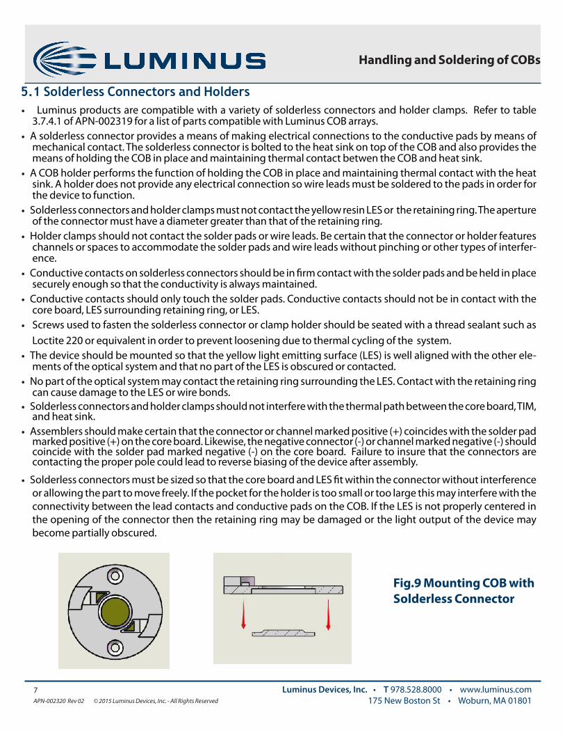
mechanical contact. The solderless connector is bolted to the heat sink on top of the COB and also provides the means of holding the COB in place and maintaining thermal contact betwen the COB and heat sink.
• A COB holder performs the function of holding the COB in place and maintaining thermal contact with the heat sink. A holder does not provide any electrical connection so wire leads must be soldered to the pads in order for the device to function.
• Solderless connectors and holder clamps must not contact the yellow resin LES or the retaining ring. The aperture of the connector must have a diameter greater than that of the retaining ring.
• Holder clamps should not contact the solder pads or wire leads. Be certain that the connector or holder features channels or spaces to accommodate the solder pads and wire leads without pinching or other types of interfer-ence.
• Conductive contacts on solderless connectors should be in firm contact with the solder pads and be held in place securely enough so that the conductivity is always maintained.
• Conductive contacts should only touch the solder pads. Conductive contacts should not be in contact with the core board, LES surrounding retaining ring, or LES.
• Screws used to fasten the solderless connector or clamp holder should be seated with a thread sealant such as Loctite 220 or equivalent in order to prevent loosening due to thermal cycling of the system.
• The device should be mounted so that the yellow light emitting surface (LES) is well aligned with the other ele-ments of the optical system and that no part of the LES is obscured or contacted.
• No part of the optical system may contact the retaining ring surrounding the LES. Contact with the retaining ring can cause damage to the LES or wire bonds.
• Solderless connectors and holder clamps should not interfere with the thermal path between the core board, TIM, and heat sink.
• Assemblers should make certain that the connector or channel marked positive (+) coincides with the solder pad marked positive (+) on the core board. Likewise, the negative connector (-) or channel marked negative (-) should coincide with the solder pad marked negative (-) on the core board. Failure to insure that the connectors are contacting the proper pole could lead to reverse biasing of the device after assembly.
• Solderless connectors must be sized so that the core board and LES fit within the connector without interference or allowing the part to move freely. If the pocket for the holder is too small or too large this may interfere with the connectivity between the lead contacts and conductive pads on the COB. If the LES is not properly centered in the opening of the connector then the retaining ring may be damaged or the light output of the device may become partially obscured.
Fig.9 Mounting COB with Solderless Connector

8APN-002320 Rev 02 © 2015 Luminus Devices, Inc. - All Rights Reserved
Luminus Devices, Inc. • T 978.528.8000 • www.luminus.com175 New Boston St • Woburn, MA 01801
Handling and Soldering of COBs
Fig.10 Proper Centering of LES in Holder Fig.11 Improper Centering of LES in Holder
6.0 Reflectors and Other Secondary OpticsSecondary optics are used in conjunction with Luminus COB arrays to produce a wide variety of lighting for nu-merous applications. Some general guidelines for the use of secondary optics in conjunction with Luminus COB arrays are as follows;
• No portion of a reflector or secondary optic should contact the yellow resin LES or retaining ring. • Reflectors and secondary optics should not interfere with the thermal path between the core board, TIM, and heat
sink. • Secondary optics may be mounted to the lighting assembly by means of a holder or connector. Secondary optics
should not be connected directly to the COB• Secondary optics such as TIR lenses or other designs that feature elements in close proximity to the COB must
maintain an air gap of at least 1mm to avoid overheating the device. • For more details related to ecosystems and optical performance of Luminus COBs with reflectors, diffusers and
other secondary optics, refer to application note APN-002319
• Figure 11 illustrates how improper alignment of the holder can create pressure on the retaining ring. The retaining ring is not desiged to withstand mechanical pressure.

9APN-002320 Rev 02 © 2015 Luminus Devices, Inc. - All Rights Reserved
Luminus Devices, Inc. • T 978.528.8000 • www.luminus.com175 New Boston St • Woburn, MA 01801
Handling and Soldering of COBs
7.0 Design Files
Luminus Devices provides raytrace files for Luminus COB arrays in formats suitable for commonly used optical modeling software like Light Tools, Zemax and Trace Pro. Also provided are solid model files in .iges format which can be used by programs such as Solid Works and Pro Engineer. The files can be downloaded from the Resource Center section of the Luminus web site and can be accessed at the following URL:
www.luminus.com/resource/design.html
Fig. 13 Luminus Orientation in Virtual Models
Fig. 12 Secondary Optics

10APN-002320 Rev 02 © 2015 Luminus Devices, Inc. - All Rights Reserved
Luminus Devices, Inc. • T 978.528.8000 • www.luminus.com175 New Boston St • Woburn, MA 01801
Handling and Soldering of COBs
The products, their specifications and other information appearing in this document are subject to change by Luminus Devices without notice. Luminus Devices assumes no liability for errors that may appear in this document, and no liability otherwise arising from the application or use of the product or information contained herein. None of the information provided herein should be considered to be a representation of the fitness or suitability of the product for any particular application or as any other form of warranty. Luminus Devices’ product warranties are limited to only such warranties as accompany a purchase contract or purchase order for such products. Nothing herein is to be construed as constituting an additional warranty. No information contained in this publication may be considered as a waiver by Luminus Devices of any intellectual property rights that Luminus Devices may have in such information.
Failure Mode Effects Analysis
Design Flaw Areas of Impact Failure Effect Severity Corrective Action
Improper Handling Wire bonds, LES broken wire bond, damaged LES
reduced light output, catastropic failure Handle devices per section 2.0
electrostatic discharge die, wirebonds, conductive pads
shorted die, damaged or broken wire bonds
reduced light output, catastropic failure Handle devices per ESD guidelines
Improper alignment of sol-derless connector or holder Retaining ring, LES broken retaining ring, broken
wire bonds
reduced light output, open circuit, catastropic
failure
Observe alignment guidelines in section 5.1
Thermal grease on LES LES reduced light output, thermal overstress
reduced light output, reduced lifetime, catas-
tropic failure
Avoid contact between LES and thermal grease, clean devices per instructions in
section 2.0
Improper alignment of secondary optics LES reduced light output, damaged
die, thermal overstress
reduced light output, poor beam quality, catas-
tropic failure
Observe alignment guidelines in section 6.0
Improper mounting of device coreboard, die, LES Thermal overstress, warping of
coreboard
reduced light output, reduced lifetime, solder
reflow, catastrophic failure
Observe mounting guidelines listed in section 5.0
8.0 Failure Modes
The table below lists some common lighting system design flaws and the potential effects that can occur. The list is not comprehensive but provides some general causes of failures and the potential effects.