API571 QUESTIONS
23
© Matthews Engineering Training Ltd Slide 1 API 510 CERT API RP 571 DAMAGE MECHANISMS AFFECTING FIXED EQUIPMENT IN THE REFINING INDUSTRY This is an API RP document (Recommended practice) Still on the first edition:2003
Transcript of API571 QUESTIONS

© Matthews Engineering Training LtdSlide 1
API 510 CERT
API RP 571
DAMAGE MECHANISMS AFFECTING FIXED
EQUIPMENT IN THE REFINING INDUSTRY
This is an API RP document (Recommended practice)
Still on the first edition:2003

© Matthews Engineering Training LtdSlide 2
API 510 CERT
API RP 571
DAMAGE MECHANISMS AFFECTING FIXED
EQUIPMENT IN THE REFINING INDUSTRY
Note it specifically relates to fixed
equipment such as pipes,vessels and
exchangers(i.e. not rotating
equipment such as pumps)
Similar to API 578 (material
verification), API 571 is an
‘afterthought’ document,recently
introduced into the API syllabus to
replace obsolete ‘IRE’ documents that
covered similar subjects

© Matthews Engineering Training LtdSlide 3
API 510 CERT API RP 571
Note how this general terminology of damage mechanism
covers more than just corrosion mechanisms
API 571 is basically an information book
containing technical descriptions of
damage mechanisms
Damage mechanisms
Corrosion
mechanisms
Other
mechanisms

© Matthews Engineering Training LtdSlide 4
API 510 CERT
4.2.3 – Temper Embrittlement
4.2.7 – Brittle Fracture
4.2.9 – Thermal Fatigue
4.2.14 – Erosion/Erosion-Corrosion
4.2.16 – Mechanical Fatigue
4.3.2 – Atmospheric Corrosion
4.3.3 – Corrosion Under Insulation (CUI)
4.3.4 – Cooling Water Corrosion
4.3.5 – Boiler Water Condensate Corrosion
4.4.2 – Sulfidation
4.5.1 – Chloride Stress Corrosion Cracking (Cl-SCC)
4.5.2 – Corrosion Fatigue
4.5.3 – Caustic Stress Corrosion Cracking (Caustic Embrittlement)
5.1.2.3 – Wet H2S Damage (Blistering/HIC/SOHIC/SCC)
5.1.3.1 – High Temperature Hydrogen Attack (HTHA

© Matthews Engineering Training LtdSlide 5
API 510 CERTAPI RP 571:CONTENTS
The API 510 syllabus does not include all of API
571,only some of it…15 damage mechanisms
The contents
of API 571
API 510
syllabus sections
4.2.3 – Temper Embrittlement
4.2.7 – Brittle Fracture
4.2.9 – Thermal Fatigue
4.2.14 – Erosion/Erosion-Corrosion
4.2.16 – Mechanical Fatigue
4.3.2 – Atmospheric Corrosion
4.3.3 – Corrosion Under Insulation (CUI)
4.3.4 – Cooling Water Corrosion
4.3.5 – Boiler Water Condensate Corrosion
4.4.2 – Sulfidation
4.5.1 – Chloride Stress Corrosion Cracking (Cl-SCC)
4.5.2 – Corrosion Fatigue
4.5.3 – Caustic Stress Corrosion Cracking (Caustic Embrittlement)
5.1.2.3 – Wet H2S Damage (Blistering/HIC/SOHIC/SCC)
5.1.3.1 – High Temperature Hydrogen Attack (HTHA
© Matthews Engineering Training LtdSlide 6
API 510 CERTAPI RP 571:CONTENTS
Notice how these 15 damage mechanisms cover
several different applications:
These are
boiler/high-
temperature process
mechanisms
4.2.3 – Temper Embrittlement
4.2.7 – Brittle Fracture
4.2.9 – Thermal Fatigue
4.2.14 – Erosion/Erosion-Corrosion
4.2.16 – Mechanical Fatigue
4.3.2 – Atmospheric Corrosion
4.3.3 – Corrosion Under Insulation (CUI)
4.3.4 – Cooling Water Corrosion
4.3.5 – Boiler Water Condensate Corrosion
4.4.2 – Sulfidation
4.5.1 – Chloride Stress Corrosion Cracking (Cl-SCC)
4.5.2 – Corrosion Fatigue
4.5.3 – Caustic Stress Corrosion Cracking (Caustic Embrittlement)
5.1.2.3 – Wet H2S Damage (Blistering/HIC/SOHIC/SCC)
5.1.3.1 – High Temperature Hydrogen Attack (HTHA

© Matthews Engineering Training LtdSlide 7
API 510 CERTAPI RP 571:CONTENTS
We will deviate from the order of API 571 and look at
these in slightly more logical groupings:
This PowerPoint presentation will
look at these 4 as the first group of damaged mechanisms covered by
API 571
4.2.3 – Temper Embrittlement
4.2.7 – Brittle Fracture
4.2.9 – Thermal Fatigue
4.2.14 – Erosion/Erosion-Corrosion
4.2.16 – Mechanical Fatigue
4.3.2 – Atmospheric Corrosion
4.3.3 – Corrosion Under Insulation (CUI)
4.3.4 – Cooling Water Corrosion
4.3.5 – Boiler Water Condensate Corrosion
4.4.2 – Sulfidation
4.5.1 – Chloride Stress Corrosion Cracking (Cl-SCC)
4.5.2 – Corrosion Fatigue
4.5.3 – Caustic Stress Corrosion Cracking (Caustic Embrittlement)
5.1.2.3 – Wet H2S Damage (Blistering/HIC/SOHIC/SCC)
5.1.3.1 – High Temperature Hydrogen Attack (HTHA

© Matthews Engineering Training LtdSlide 8
API 510 CERT
API 571 COVERAGE OF THE DAMAGE
MECHANISMS
Description/appearance
of the
damage mechanism
Critical
factorsAffected
equipmentPrevention/
mitigation
Inspection/
monitoring
Related
mechanisms
API 571 looks at each of the damage mechanisms in this way:
Have a look at the
sections of API 571
and you will see this
pattern
© Matthews Engineering Training LtdSlide 9
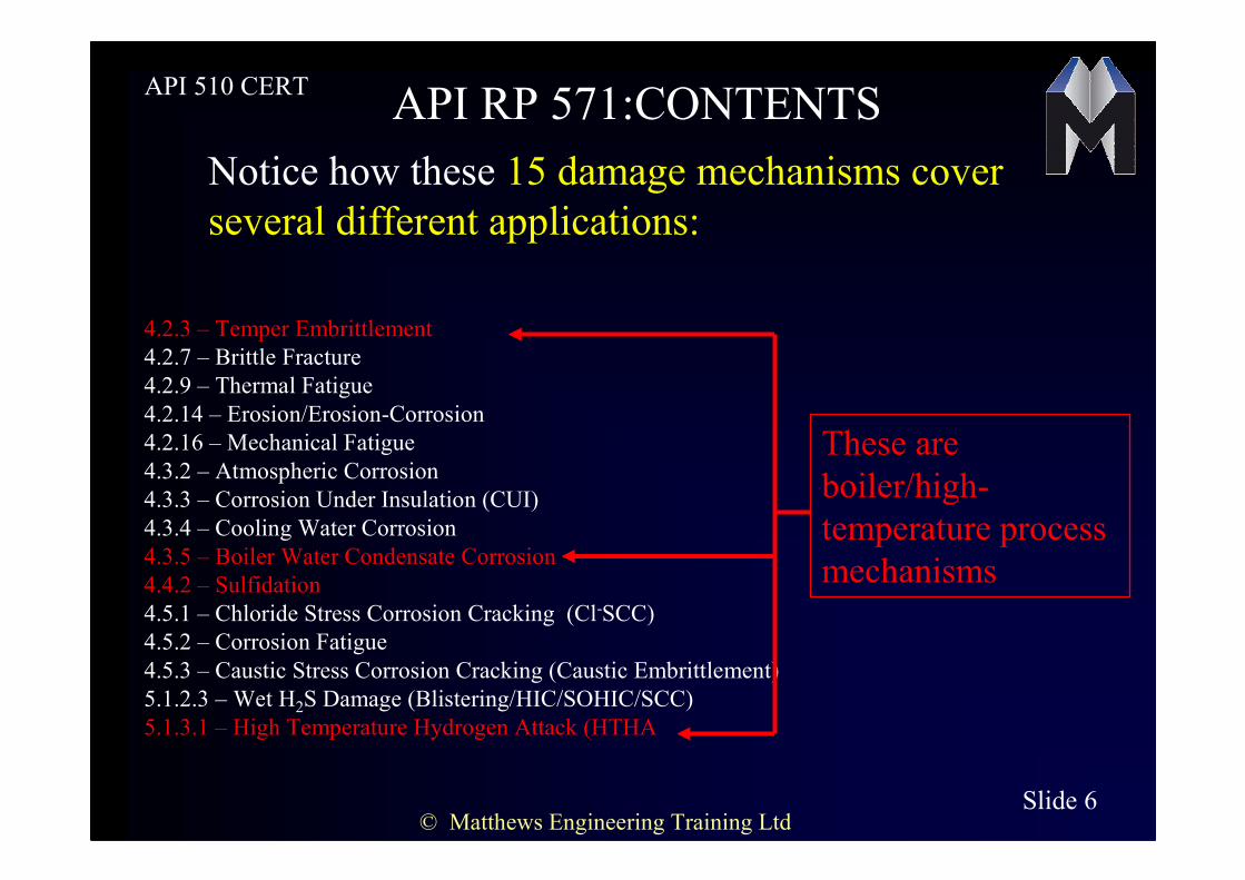
API 510 CERTBRITTLE FRACTURE
It’s a failure mechanism…not a corrosion mechanism,as such
Sudden fracture of the material without
any plastic deformation
Flat
fracture
face
Cracks tend to
be straight

© Matthews Engineering Training LtdSlide 10
API 510 CERTBRITTLE FRACTURE
Caused by hydro-testing and/or
operating below the Charpy impact
transition temperature
Low temperature during pressure test
=Low ductility
=Low impact strength
=
Failure

© Matthews Engineering Training LtdSlide 11
API 510 CERT
BRITTLE FRACTURE
Vulnerable materials
400
Plain carbon steels
Low alloy steels(1-2%Cr
etc)
400-series stainless steels

© Matthews Engineering Training LtdSlide 12
API 510 CERTTEMPER EMBRITTLEMENT
This is a specific type of brittle fracture failure…a different
cause and different effect to the ‘low temperature’ type
THE CAUSE IS:
THE EFFECT IS
Prolonged exposure to
temperatures
342-593 degC (650-1100 degF).
Reduction in toughness(impact strength)
during start-up and shutdown (rather than
at operating temperature) leading to brittle
fracture

© Matthews Engineering Training LtdSlide 13
API 510 CERTTEMPER EMBRITTLEMENT
Its an alloy-specific damage mechanism
AFFECTED
MATERIALS:
2 ¼ Cr –Mo low alloy steels and
similar.Used in boilers,refinery
reactors,cat crackers,cokers etc
The susceptibility to temper embrittlement is a function of trace
element composition:Manganese,Silicon, and trace elements P,Sn etc

© Matthews Engineering Training LtdSlide 14
API 510 CERTTEMPER EMBRITTLEMENT
NOTE THESE POINTS ON TEMPERATURE RANGE
342 degC 593 degC
482degC440degC
The general susceptibility range
Range for 2 ¼ Cr-1Mo
Temper embrittlement develops
more quickly at 482 degC
But the damage is more
severe after prolonged
exposure at 440 degC BUT

© Matthews Engineering Training LtdSlide 15
API 510 CERTTEMPER EMBRITTLEMENT
The effect is an increase in the temperature at which the
material becomes brittle
API 571 describes this as: an
upward shift in the ductile-to-
brittle transition temperature
Read the other technical details in
API 571 4.2.3.6NOW

© Matthews Engineering Training LtdSlide 16
API 510 CERTTHERMAL FATIGUE
The result of cyclic stresses caused by temperature variations
Variations of more than about 93
degC (200 degF) can cause
thermal fatigue
Rule of thumbCracks lead to
failure

© Matthews Engineering Training LtdSlide 17
API 510 CERTTHERMAL FATIGUE
On a macro scale,cracks
tend to be dagger-shaped
,wide and oxide-
filled(caused by the
oxidising effect of the
temperature variations)
Here,joint restraint
has caused excessive
thermal stresses to
occur

© Matthews Engineering Training LtdSlide 18
API 510 CERT
MECHANICAL FATIGUE
The result of cyclic stresses caused by mechanical loadings
Common around stress
concentrations
•Changes of section
•Keyways
•Rough welds
•Thread notches
Fatigue crack in progress Propagation to failure

© Matthews Engineering Training LtdSlide 19
API 510 CERTENDURANCE LIMIT
(sometimes called Fatigue limit)
Stress
amplitude S
Number of cycles N
Below this stress,
the material will not suffer
fatigue cracking ,no matter
how many stress cycles it
sees
•Plain Carbon steels
•Low alloy steels
•Titanium
DO have an
endurance limit
Many other materials e.g
300/400 stainless steels,and
aluminium DO NOT have
an endurance limit
BUT

© Matthews Engineering Training LtdSlide 20
API 510 CERTENDURANCE LIMIT
Stress
S
Cycles N
For materials that do have
an endurance limit:
Rule of thumb
The limit is about 40-
50% of UTS:
UTS

© Matthews Engineering Training LtdSlide 21
API 510 CERT
MECHANICAL FATIGUE
Mechanical fatigue failure is characterised by ‘Beach Marks’
resulting from progressive propagation and arrest of the crack
API 571 prefers to call multiple
initiation points and beach marks a
‘clam shell fingerprint’

© Matthews Engineering Training LtdSlide 22
API 510 CERT
VIBRATION-INDUCED FATIGUE
This is simply mechanical fatigue caused by induced vibrations
•Water hammer
•‘Flash-off’ of fluid
•Small-bore pipes that are unsupported
•Vortex-vibration in heat exchangers
•Failure of pipe hangers
Typical causes:
Failures commonly occur at
socket welded or threaded joints:
Like these:
© Matthews Engineering Training LtdSlide 23
API 510 CERT
BEFORE PROCEEDING
FURTHER……
Check now that you understand the difference between brittle fracture
and fatigue.
Have a look in your copy of API 571 at the mechanisms covered in this
presentation and read the ‘affected materials’ and
‘Prevention/mitigation’ sections for each of these mechanisms
After that , return to the module text itself and we’ll look at some more
of the damage mechanisms that are described in API 571
571