API Specification 5LD 4th Mar. 2015 CRA Clad or Lined Steel Pipe
46
CRA Clad or Lined Steel Pipe API SPECIFICATION 5LD FOURTH EDITION, MARCH 2015 API MONOGRAM PROGRAM EFFECTIVE DATE: SEPTEMBER 3, 2015 Copyright American Petroleum Institute Provided by IHS under license with API No reproduction or networking permitted without license from IHS
-
Upload
juan-salazar -
Category
Documents
-
view
1.220 -
download
314
description
..
Transcript of API Specification 5LD 4th Mar. 2015 CRA Clad or Lined Steel Pipe

CRA Clad or Lined Steel Pipe
API SPECIFICATION 5LDFOURTH EDITION, MARCH 2015
API MONOGRAM PROGRAM EFFECTIVE DATE: SEPTEMBER 3, 2015
Copyright American Petroleum Institute Provided by IHS under license with API No reproduction or networking permitted without license from IHS

Special Notes
API publications necessarily address problems of a general nature. With respect to particular circumstances, local,state, and federal laws and regulations should be reviewed.
Neither API nor any of API’s employees, subcontractors, consultants, committees, or other assignees make anywarranty or representation, either express or implied, with respect to the accuracy, completeness, or usefulness of theinformation contained herein, or assume any liability or responsibility for any use, or the results of such use, of anyinformation or process disclosed in this publication. Neither API nor any of API’s employees, subcontractors,consultants, or other assignees represent that use of this publication would not infringe upon privately owned rights.
API publications may be used by anyone desiring to do so. Every effort has been made by the Institute to assure theaccuracy and reliability of the data contained in them; however, the Institute makes no representation, warranty, orguarantee in connection with this publication and hereby expressly disclaims any liability or responsibility for loss ordamage resulting from its use or for the violation of any authorities having jurisdiction with which this publication mayconflict.
API publications are published to facilitate the broad availability of proven, sound engineering and operatingpractices. These publications are not intended to obviate the need for applying sound engineering judgmentregarding when and where these publications should be utilized. The formulation and publication of API publicationsis not intended in any way to inhibit anyone from using any other practices.
Any manufacturer marking equipment or materials in conformance with the marking requirements of an API standardis solely responsible for complying with all the applicable requirements of that standard. API does not represent,warrant, or guarantee that such products do in fact conform to the applicable API standard.
Classified areas may vary depending on the location, conditions, equipment, and substances involved in any givensituation. Users of this Specification should consult with the appropriate authorities having jurisdiction.
Users of this Specification should not rely exclusively on the information contained in this document. Sound business,scientific, engineering, and safety judgment should be used in employing the information contained herein.
All rights reserved. No part of this work may be reproduced, translated, stored in a retrieval system, or transmitted by any means, electronic, mechanical, photocopying, recording, or otherwise, without prior written permission from the publisher. Contact the
Publisher, API Publishing Services, 1220 L Street, NW, Washington, DC 20005.
Copyright © 2015 American Petroleum Institute
Copyright American Petroleum Institute Provided by IHS under license with API No reproduction or networking permitted without license from IHS

iii
Foreword
This edition of API Specification 5LD supersedes the Third Edition and includes items approved by letter ballot from January 2014. Portions of this publication have been changed from the previous edition. Substantive changes are indicated with gray shading and blue font, but API makes no warranty as to the accuracy of such notations. Nonsubstantive changes will not be indicated with shading and colored font.
Nothing contained in any API publication is to be construed as granting any right, by implication or otherwise, for the manufacture, sale, or use of any method, apparatus, or product covered by letters patent. Neither should anything contained in the publication be construed as insuring anyone against liability for infringement of letters patent.
The verbal forms used to express the provisions in this recommended practice are as follows: — the term “shall” denotes a minimum requirement in order to conform to the recommended practice;
— the term “should” denotes a recommendation or that which is advised but not required in order to conform to the recommended practice;
— the term “may” is used to express permission or a provision that is optional; and
— the term “can” is used to express possibility or capability.
This document was produced under API standardization procedures that ensure appropriate notification and participation in the developmental process and is designated as an API standard. Questions concerning the interpretation of the content of this publication or comments and questions concerning the procedures under which this publication was developed should be directed in writing to the Director of Standards, American Petroleum Institute, 1220 L Street, NW, Washington, DC 20005. Requests for permission to reproduce or translate all or any part of the material published herein should also be addressed to the director.
Generally, API standards are reviewed and revised, reaffirmed, or withdrawn at least every five years. A one-time extension of up to two years may be added to this review cycle. Status of the publication can be ascertained from the API Standards Department, telephone (202) 682-8000. A catalog of API publications and materials is published annually by API, 1220 L Street, NW, Washington, DC 20005.
Suggested revisions are invited and should be submitted to the Standards Department, API, 1220 L Street, NW, Washington, DC 20005, [email protected].
Copyright American Petroleum Institute Provided by IHS under license with API No reproduction or networking permitted without license from IHS

Copyright American Petroleum Institute Provided by IHS under license with API No reproduction or networking permitted without license from IHS

v
Contents page
1 Scope ....................................................................................................................................................... 1 1.1 Coverage ................................................................................................................................................. 1 1.2 Application of the API Monogram ........................................................................................................ 1
2 Normative References ........................................................................................................................... 1
3 Terms, Definitions, and Abbreviations ................................................................................................ 3 3.1 Terms and Definitions ............................................................................................................................ 3 3.2 Abbreviations ......................................................................................................................................... 3
4 General Information ............................................................................................................................... 4 4.1 Pipe Size .................................................................................................................................................. 4 4.2 Information to be Supplied by the Purchaser ..................................................................................... 4 5 Manufacturing of Clad and Lined Steel Pipe ....................................................................................... 6 5.1 General .................................................................................................................................................... 6 5.2 Description of Clad and Lined Steel Pipe ............................................................................................ 6 6 Chemical Properties and Tests ............................................................................................................. 7 6.1 Composition............................................................................................................................................ 7 6.2 Heat Analyses of the CRA Layer .......................................................................................................... 7 6.3 Product Analyses of Backing Steel, Welds, and CRA ........................................................................ 7 6.4 Recheck Analyses .................................................................................................................................. 8
7 Mechanical Properties and Tests ......................................................................................................... 9 7.1 Mechanical Properties (Backing Steel) ................................................................................................ 9 7.2 Tensile Tests—General .......................................................................................................................... 9 7.3 Testing Frequency ................................................................................................................................. 9 7.4 Longitudinal Tensile Tests .................................................................................................................... 9 7.5 Transverse Tensile Tests ...................................................................................................................... 9 7.6 Weld Tensile Tests ................................................................................................................................. 9 7.7 Control Tensile Tests ............................................................................................................................. 9 7.8 Retests (Tensile) ................................................................................................................................... 11 7.9 Flattening Tests .................................................................................................................................... 11 7.10 Guided-bend Tests ............................................................................................................................... 12 7.11 Fracture Toughness Tests .................................................................................................................. 12 7.12 Metallographic Examination ................................................................................................................ 13 7.13 Hardness Test ....................................................................................................................................... 14
8 Special Tests ........................................................................................................................................ 16 8.1 Ferrite/Austenite Ratio for Duplex Stainless Steel ........................................................................... 16 8.2 Corrosion Testing ................................................................................................................................ 16 8.3 Tests for CRA Cladding Bond Strength and CRA Liner Tightness................................................. 17 8.4 Residual Magnetism ............................................................................................................................. 18
9 Hydrostatic Tests�Inspection Hydrostatic Test ............................................................................... 18
10 Dimensions, Weights, and Lengths ................................................................................................... 19 10.1 Dimension and Weights ....................................................................................................................... 19 10.2 Diameter ................................................................................................................................................ 19 10.3 Wall Thickness ..................................................................................................................................... 20 10.4 Mass ....................................................................................................................................................... 20 10.5 Length .................................................................................................................................................... 20 10.6 Straightness .......................................................................................................................................... 20 10.7 Jointers .................................................................................................................................................. 20 10.8 Pipe Ends .............................................................................................................................................. 21
Copyright American Petroleum Institute Provided by IHS under license with API No reproduction or networking permitted without license from IHS

vi
Contents page
11 Nondestructive Inspection .................................................................................................................. 21 11.1 Inspection Methods for Welded Clad Pipe ......................................................................................... 21 11.2 Inspection Methods for Seamless Clad Pipe ..................................................................................... 22 11.3 Inspection Methods for Lined Pipe ..................................................................................................... 22 11.4 Thickness of Cladding or Lining ......................................................................................................... 23 12 Workmanship, Visual Inspection, and Repair of Defects ................................................................. 23 12.1 Workmanship .......................................................................... 23 12.2 Visual Inspection .................................................................................................................................. 23 12.3 Defects and Disbonding ...................................................................................................................... 23 12.4 Surface Treatment ................................................................................................................................ 23 13 Marking .................................................................................................................................................. 24 13.1 General .................................................................................................................................................. 24 13.3 Pipe Processor Markings ..................................................................................................................... 25 14 Documentation ..................................................................................................................................... 26 14.1 Certification ........................................................................................................................................... 26 14.2 Electronic Certificate of Compliance .................................................................................................. 26 Annex A (informative) API Monogram Program Use of the API Monogram by Licensees ...................... 27
Annex B (normative) Manufacturing Procedure Specification ................................................................... 31
Annex C (normative) Welding Procedure Qualification Requirements ..................................................... 33 Annex D (normative) Manufacturing Procedure Qualification Test ........................................................... 34
Annex E (normative) Jointer Requirements .................................................................................................. 36
Annex F (normative) Purchaser Inspection .................................................................................................. 37
Bibliography ................................................................................................................................................... 38
Figures 1 Welded Clad Pipe or Lined Pipe When Process Involves Seam Welding of the CRA ................... 14 2 Seamless Clad Pipe .............................................................................................................................. 15
Tables 1 Purchaser Supplied Information ........................................................................................................... 5 2 Purchaser Provided Analysis ................................................................................................................ 8 3 Chemical Requirements for Heat Analysis of CRA Layer, Percent (%) .......................................... 10 4 Acceptance Criteria for Examination of Weld Microstructure ......................................................... 13 5 Hardness Survey of Four Traverses for SAW Clad Pipe or Lined Pipe .......................................... 14 6 Hardness Survey of Two Traverses for Seamless Clad Pipe .......................................................... 15 7 Hardness Test Requirements .............................................................................................................. 15 8 Young’s Modulus and Poisson’s Ratio at 25 °C (77 °F) .................................................................... 18 9 Correction Factors ............................................................................................................................... 19 10 Tolerances on Dimensions and Weights ........................................................................................... 21
Copyright American Petroleum Institute Provided by IHS under license with API No reproduction or networking permitted without license from IHS

1
CRA Clad or Lined Steel Pipe
1 Scope
1.1 Coverage
This specification covers seamless and welded clad steel line pipe and lined steel line pipe with enhanced corrosion-resistant properties suitable for use in pipeline transportation systems in the petroleum and natural gas industries. The clad and lined steel line pipe specified herein is composed of a carbon steel backing or base material outside (in some cases inside and/or outside) and a corrosion-resistant alloy (CRA) layer or lining inside of the pipe. The base material conforms to API 5L (45th Ed.), product specification level (PSL) 2 and applicable annex(es), except as modified herein.
Grades of base material covered by this specification include X42, X46, X52, X56, X60, X65, X70, X80, and grades intermediate to these. Grades of the CRA layer are LC 1812, 2205, 2506, 2242, 2262, unified numbering system (UNS) S31703, UNS N08904, UNS N10276, Alloy 31™1 (UNS N08031), Alloy 59 (UNS N06059), Alloy 254 SMO™ 11 (UNS S31254), Alloy 400 (UNS N04400), AL6NX (UNS N08367), and EN 1.4529 (UNS N08926). Other grades are subject to agreement between the purchaser and the manufacturer.
The delivered product usually has square ends, but other special ends may be furnished by agreement between the purchaser and manufacturer. Included are nominal pipe sizes (NPS) 25 mm (1 in.) through 2134 mm (84 in.). Sizes greater than 2134 mm (84 in.) are outside of the range of API 5L (45th Ed.) but may be supplied up to 2500 mm (100 in.) by agreement, including requirements for materials.
1.2 Application of the API Monogram
If product is manufactured at a facility licensed by API and it is intended to be supplied bearing the API Monogram, the requirements of Annex A apply.
2 Normative References
The following referenced documents are indispensable for the application of this document. For dated references, only the edition cited applies. For undated references, the latest edition of the referenced document (including any amendments) applies. For a list of other documents and articles associated with this standard, please see the Bibliography.
API Specification 5L, Specification for Line Pipe, 45th Edition, December 2012 (Effective July 1, 2013)
API Specification 5LC, Specification for CRA Line Pipe, Fourth Edition
API Specification Q1, Specification for Quality Management System Requirements for Manufacturing Organizations for the Petroleum and Natural Gas Industry, Ninth Edition, June 2013
ANSI 2/NACE 3 MR0175/ISO 15156-3:2009(E), Petroleum and natural gas industries—Materials for use in H2S-containing environments in oil and gas production—Parts 1, 2, and 3
ASME Boiler and Pressure Vessel Code (BPVC) 4, Section II, Part C: Specifications for Welding Rods, Electrodes and Filler Metals (2013.07.01)
1 This term is used as an example only, and does not constitute an endorsement of this product by API. 2 American National Standards Institute, 1899 L Street, NW, 11th Floor, Washington, DC 20036, www.ansi.org. 3 NACE International, 1440 South Creek Drive, Houston, Texas 77084, www.nace.org. 4 ASME International, 2 Park Avenue, New York, New York 10016-5990, www.asme.org.
Copyright American Petroleum Institute Provided by IHS under license with API No reproduction or networking permitted without license from IHS

2 API SPECIFICATION 5LD
ASME BPVC, Section IX: Welding and Brazing Qualifications (2013.07.01)
ASTM A240-14 5, Standard Specification for Chromium and Chromium-Nickel Stainless Steel Plate, Sheet, and Strip for Pressure Vessels and for General Applications
ASTM A262-13, Standard Practices for Detecting Susceptibility of Intergranular Attack in Austenitic Stainless Steels
ASTM A263-12, Standard Specification for Stainless Chromium Steel-Clad Plate
ASTM A264-12, Specification for Stainless Chromium-Nickel Steel Clad Plate
ASTM A265-12, Standard Specification for Nickel and Nickel-Base Alloy-Clad Steel Plate
ASTM A578-07, Standard Specification for Straight-Beam Ultrasonic Examination of Rolled Steel Plates for Special Applications
ASTM A751-14, Standard Test Methods, Practices and Terminology for Chemical Analysis of Steel Products
ASTM B424-11, Standard Specification for Ni-Fe-Cr-Mo-Cu Alloy (UNS N08825 and UNS N08221) Plate, Sheet, and Strip
ASTM B443-00, Standard Specification for Nickel-Chromium-Molybdenum-Columbium Alloy (UNS N06625) and Nickel-Chromium-Molybdenum-Silicon Alloy (UNS N06219) Plate, Sheet, and Strip
ASTM B619-10, Standard Specification for Welded Nickel and Nickel-Cobalt Alloy Pipe
ASTM B622-10, Standard Specification for Seamless Nickel and Nickel-Cobalt Alloy Pipe and Tube
ASTM B675-01 (2013), Standard Specification for UNS N08367 Welded Pipe
ASTM E18-14, Standard Test Methods for Rockwell Hardness of Metallic Materials
ASTM E165-12, Standard Test Method for Liquid Penetrant Examination
ASTM E353-1993, Standard Test Methods for Chemical Analysis of Stainless, Heat-Resisting, Maraging, and Other Similar Chromium-Nickel-Iron Alloys
ASTM E384-11, Standard Test Method for Knoop and Vickers Hardness of Materials
ASTM E562-11, Standard Test Method for Determining Volume Fraction by Systematic Manual Point Count
ASTM G28-02, Standard Test Methods of Detecting Susceptibility to Intergranular Corrosion in Wrought, Nickel-Rich, Chromium-Bearing Alloys
ASTM G48-11, Standard Test Methods for Pitting and Crevice Corrosion Resistance of Stainless Steels and Related Alloys by Use of Ferric Chloride Solution
ISO/TR 9769:1991 6, Steel and iron—Review of available methods of analysis
5 ASTM International, 100 Barr Harbor Drive, West Conshohocken, Pennsylvania 19428, www.astm.org. 6 International Organization for Standardization, 1, ch. de la Voie-Creuse, CH-1211 Geneva 20, Switzerland,
www.iso.org.
Copyright American Petroleum Institute Provided by IHS under license with API No reproduction or networking permitted without license from IHS

CRA CLAD OR LINED STEEL PIPE 3
3 Terms, Definitions, and Abbreviations 3.1 Terms and Definitions
For the purposes of this specification the following definitions apply.
3.1.1 backing steel The outer wall thickness pipe of a clad or lined pipe (for pipe clad on the outside and inside, the backing steel is the core material).
NOTE Backing steel is sometimes referred to as base material or steel backing.
3.1.2 clad cladding Refers to a metallurgically bonded CRA layer produced by roll bonding, weld overlaying, powder metallurgy, or explosively cladding a carbon steel plate or pipe.
3.1.3 CRA layer A general term referring to any internal corrosion-resistant alloy layer.
3.1.4 lined Refers to a mechanically expanded, fitted or installed (“mechanical bond”) CRA layer with a carbon backing steel.
3.1.5 manufacturer As used throughout this specification refers to the firm, company, or corporation responsible for marking the product and warrants that the product conforms to the specification.
NOTE The manufacturer may be either a pipe mill or a processor, as applicable. The manufacturer is responsible for compliance with all of the applicable provisions of the specification.
3.1.6 pipe mill A firm, company, or corporation that operates pipe-making facilities.
3.1.7 processor A firm, company, or corporation that operates facilities capable of heat treating pipe made by a pipe mill.
3.2 Abbreviations
For the purposes of this specification the following abbreviations apply.
CVN Charpy V-notch
CRA corrosion-resistant alloy
DWTT drop weight tear tests
GTAW gas tungsten arc welding
HAZ heat-affected zone
MPQT manufacturing procedure qualification test
MPS manufacturing procedure specification
NPS nominal pipe size
Copyright American Petroleum Institute Provided by IHS under license with API No reproduction or networking permitted without license from IHS

4 API SPECIFICATION 5LD
PAW (PTA) plasma arc welding (sometimes referred to as plasma tungsten arc)
PREN (PREW) pitting resistance equivalent number
PSL product specification level
RES resistance electroslag welding
SMYS specified minimum yield strength
TMCP thermomechanical controlled processing
UNS unified numbering system
UT ultrasonic testing
WPS welding procedure specification
4 General Information 4.1 Pipe Size
The size designations are nominal pipe sizes. In the text, where pipe size limits (or size ranges) are given, these are outside-diameter sizes except where stated to be nominal. These outside-diameter size limits and ranges apply also to the corresponding nominal sizes.
USC units in this specification are shown in parentheses in the text and in many tables. Outside diameters and wall thicknesses are converted from inch dimensions. The converted diameters are rounded to the nearest 0.1 mm for diameters less than 18 in. and to the nearest 1 mm for diameters 18 in. and larger. Wall thicknesses are rounded to the nearest 0.1 mm.
Metric plain-end weights are calculated from the metric outside diameters and wall thicknesses using the equations in 10.1 and rounded to the nearest 0.01 kg/m (0.01 lb/ft).
Metric hydrostatic pressures are calculated from metric outside diameters and wall thicknesses and metric fiber stresses shown in Section 9.
The factors used where conversions are appropriate are as follows:
1 inch (in.) = 25.4 millimeters (mm) exactly
1 square inch (in.2) = 645.16 square millimeters (mm2) exactly
1 foot (ft) = 0.3048 meters (m) exactly
1 pound (lb) = 0.45359 kilograms (kg)
1 pound per foot (lb/ft) = 1.4882 kilograms per meter (kg/m)
1 pound per square inch (psi) = 6.895 kilopascals (kPa) for pressure
= 0.006895 megapascals (MPa) for stress
1 foot-pound (ft-lb) = 1.3558 Joules (J) for impact energy
Equation (1) below was used to convert degrees Fahrenheit (°F) to degrees Celsius (°C):
( )° = ° −5C F 32
9 (1)
4.2 Information to be Supplied by the Purchaser
In placing orders for CRA clad or lined pipe in accordance with API 5LD, the purchaser shall specify the following from Table 1 on the purchase order.
Copyright American Petroleum Institute Provided by IHS under license with API No reproduction or networking permitted without license from IHS

CRA CLAD OR LINED STEEL PIPE 5
Table 1—Purchaser Supplied Information
Requirement API 5LD or API 5L (if Noted) Section/Table/Figure Number
Specification 5LD
Quantity of pipe in feet or meters As specified on the purchase order
Type of pipe: clad or lined Section 5.2
Process of manufacture: seamless, welded Section 5.2
Grade of backing steel material (PSL 2 only) 5L (45th Ed.), Table 1
Material or CRA clad or liner material Table 3
Type of CRA layer Section 5.2
Nominal diameter (size) of backing steel 5L (45th Ed.), Table 9
Wall thickness (nominal) of backing steel 5L (45th Ed.), Table 9
Minimum thickness of CRA cladding or liner Section 5
Nominal length of joint 5L (45th Ed.), Section 9.11.1.3
End finish 5L (45th Ed.), Section 9.12
The purchaser shall also state on the purchase order requirements concerning the following stipulations API 5LD Section/Table/Figure Number
Chemical analysis reports Sections 6.1 to 6.6
PREN or PREW if required Section 6.1
Defect repair procedures Section 12.3
Chemical requirements for the CRA layer Table 3
Mechanical properties of CRA layer and backing Section 7; 5L (45th Ed.), Section 9.3
CVN shear requirements Section 7.11.3
CRA layer bonding test Section 8.3
OD tolerance applied to ID Section 10.2 and Table 10
Wall thickness positive tolerance for clad pipe Table 10
Jointers Section 10.7
NDT of welded clad pipe Section 11.1
NDT of seamless clad pipe Section 11.2
NDT of lined pipe Section 11.3
Continuity of CRA layer Section 12.2
Repair of defects in CRA layer Section 12.3
Certification Section 14.1
Annexes
Manufacturing procedure specification Annex B
Welding procedure specification (WPS) requirements Annex C
Manufacturing procedure qualification test Annex D
Jointer requirements Annex E
Purchaser Inspection Annex F
Copyright American Petroleum Institute Provided by IHS under license with API No reproduction or networking permitted without license from IHS
6 API SPECIFICATION 5LD
5 Manufacturing of Clad and Lined Steel Pipe
5.1 General
Clad pipe or lined steel pipe furnished to this specification shall be seamless or welded, as defined below. All welding consumables shall comply with the requirements of ASME BPVC Section II, Part C (2013.07.01). The thickness of the CRA layer shall be a minimum of 2.5 mm (0.100 in.) unless otherwise agreed to.
NOTE Thinner CRA cladding has been used for some applications.
5.2 Description of Clad and Lined Steel Pipe
Clad Pipe 5.2.1
Clad pipe is a bimetallic pipe composed of an internal (and in some cases external) CRA layer that is metallurgically bonded to the backing steel. The cladding may be bonded by hot rolling, coextrusion, weld overlay, explosion bonding, powder metallurgy, or some other process that produces a metallurgical bond. Clad pipe may be either seamless or welded as follows.
a) Seamless. Seamless clad pipe is produced by the seamless process defined in API 5L (45th Ed.), Section 8.1 and shall meet the requirements of API 5L (45th Ed.), PSL 2.
b) Welded. Welded clad pipe is produced from plate or skelp that has been clad by one of the processes described in 5.2.1. The backing material shall meet the requirements of API 5L (45th Ed.), PSL 2. The longitudinal seam of the backing steel shall be welded by one of the welding processes included in API 5L (45th Ed.), Section 8.1 except as follows. In addition, gas tungsten arc welding (GTAW) is acceptable for the tack welds, and plasma arc welding (plasma tungsten arc) [PAW (PTA)] is acceptable for the seam welds provided appropriate qualifications to API 5L (45th Ed.), Annex B are performed. For welding of the cladding material, processes in API 5LC (4th Ed.), Section 5.1 b) or resistance electroslag welding (RES) welding and PAW are permitted.
Lined Pipe 5.2.2
Lined pipe consists of a carbon steel pipe meeting the requirements of API 5L (45th Ed.), PSL 2 with an internal or external CRA liner. The CRA liner is affixed or tightly fitted to the external pipe full length by expansion, compression cold forming, or some other means. The CRA liner may be a tube or pipe inserted into a steel pipe, a plate or sheet rolled into a cylinder by expanding the liner and/or shrinking the pipe, or by some other applicable processes. Lined pipe may be either seamless or welded as follows.
a) Seamless. Seamless lined pipe consists of an outer seamless pipe made to the requirements of API 5L (45th Ed.), PSL 2.
b) Welded. Welded lined pipe consists of an outer welded pipe made to the requirements of API 5L (45th Ed.), PSL 2. The liner may be either seamless or welded manufactured to the requirements of API 5LC (4th Ed.) or other appropriate industry standard. Alternatively, weld lined pipe may be made by co-rolling a sandwich of a carbon steel plate and a CRA plate into a cylinder followed by longitudinally welding the long edges to form a seam in the backing steel and CRA liner materials.
5.3 Cold Sizing and Cold Expansion
5.3.1 Unless otherwise agreed, the sizing ratio for the backing steel shall not be more than 1.5 % unless the entire part of the pipe that is cold sized is subsequently normalized, quenched, and tempered or stress relieved.
5.3.2 If cold sized or cold expanded pipe, which is not subsequently heat treated or stress relieved, is used as the backing steel, the strains applied during manufacturing of the pipe used as the backing steel shall be considered in addition to those applied during lining or sizing of the pipe after lining or cladding. In this case, the
Copyright American Petroleum Institute Provided by IHS under license with API No reproduction or networking permitted without license from IHS

CRA CLAD OR LINED STEEL PIPE 7
sum of the sizing ratios for all manufacturing steps applied to the backing steel shall not exceed 2.0 % unless otherwise agreed.
5.3.3 Sizing ratio shall be determined as described in API 5L (45th Ed.), Section 8.9.3.
5.3.4 Following all sizing operations and processing the produced pipe shall be tested for conformance to mechanical and Charpy toughness properties per the requirements of Section 7.
5.4 Heat Treatment
Pipe furnished to this specification may be as-rolled, solution-annealed (for the CRA liner), normalized, thermomechanical controlled processing (TMCP), TMCP with accelerated cooling, or quench-and-tempered. For lined pipe, heat treatment may be applied to the outer pipe and the inner pipe, individually, before inserting the liner. The CRA inner pipe shall be supplied in the solution annealed condition unless otherwise agreed. Other appropriate heat treatments may be agreed upon between purchaser and manufacturer.
NOTE In order to ensure that satisfactory corrosion properties are consistently achieved in the clad layer, it is important to generate a high level of reproducibility in any heat treatment cycle.
Consequently, the manufacturer should minimize the heat treatment time and temperature tolerances. Following heat treatment, the CRA material shall demonstrate appropriate microstructure and anti-corrosion properties.
6 Chemical Properties and Tests
6.1 Composition
The composition of the CRA layer furnished to this specification, as determined by heat or deposit analyses, shall conform to the chemical requirements specified in Table 1. Chemical composition of the as deposited overlay of the seam or girth weld (in the case of a jointer) shall be within the tolerances of the clad layer or as agreed upon between the purchaser and manufacturer.
When agreed and specified on the purchase order or datasheet, the chemical composition of any CRA cladding or liner may be further restricted by specification of a minimum pitting resistance equivalent number (PREN) (% Cr + 3.3 % Mo + 16 % N) or PREW [% Cr + 3.3 (% Mo + 0.5 % W) + 16 % N] value. If this is the case, the actual values shall be reported on the material test certificate.
6.2 Heat Analyses of the CRA Layer
The manufacturer shall furnish a report containing the heat analysis of each heat of material used in the manufacture of the CRA layer for pipe furnished on the purchase order. The analysis so determined shall conform to the requirements specified in 6.1.
If alloying elements other than those specified in Table 3 for a particular grade of CRA layer are added for other than deoxidation purposes, the heat analyses, including the alloy additions, shall be reported for each heat applied to the purchaser’s order.
6.3 Product Analyses of Backing Steel, Welds, and CRA
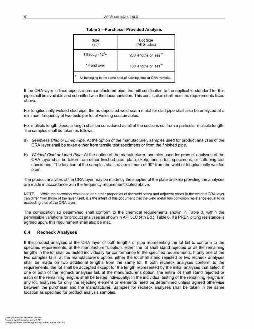
One test from each of two lengths of pipe or plate or skelp from each lot size as indicated in Table 2 shall be analyzed for product analyses. Both the CRA layer and the backing steel shall be analyzed. The analysis may be taken from the plate for clad pipe prior to rolling into pipe, and from the outer and inner pipes for lined pipe prior to insertion of the CRA pipe in the backing steel pipe. The results of the analyses shall be provided to the purchaser.
Copyright American Petroleum Institute Provided by IHS under license with API No reproduction or networking permitted without license from IHS
8 API SPECIFICATION 5LD
Table 2—Purchaser Provided Analysis
Size (in.)
Lot Size (All Grades)
1 through 123/4 200 lengths or less a
14 and over 100 lengths or less a
a All belonging to the same heat of backing steel or CRA material.
If the CRA layer in lined pipe is a premanufactured pipe, the mill certification to the applicable standard for this pipe shall be available and submitted with the documentation. This certification shall meet the requirements listed above.
For longitudinally welded clad pipe, the as-deposited weld seam metal for clad pipe shall also be analyzed at a minimum frequency of two tests per lot of welding consumables.
For multiple length pipes, a length shall be considered as all of the sections cut from a particular multiple length. The samples shall be taken as follows.
a) Seamless Clad or Lined Pipe. At the option of the manufacturer, samples used for product analyses of the CRA layer shall be taken either from tensile test specimens or from the finished pipe.
b) Welded Clad or Lined Pipe. At the option of the manufacturer, samples used for product analyses of the CRA layer shall be taken from either finished pipe, plate, skelp, tensile test specimens, or flattening test specimens. The location of the samples shall be a minimum of 90° from the weld of longitudinally welded pipe.
The product analyses of the CRA layer may be made by the supplier of the plate or skelp providing the analyses are made in accordance with the frequency requirement stated above.
NOTE While the corrosion resistance and other properties of the weld seam and adjacent areas in the welded CRA layer can differ from those of the layer itself, it is the intent of this document that the weld metal has corrosion resistance equal to or exceeding that of the CRA layer.
The composition so determined shall conform to the chemical requirements shown in Table 3, within the permissible variations for product analyses as shown in API 5LC (4th Ed.), Table 6. If a PREN pitting resistance is agreed upon, this requirement shall also be met.
6.4 Recheck Analyses
If the product analyses of the CRA layer of both lengths of pipe representing the lot fail to conform to the specified requirements, at the manufacturer’s option, either the lot shall stand rejected or all the remaining lengths in the lot shall be tested individually for conformance to the specified requirements. If only one of the two samples fails, at the manufacturer’s option, either the lot shall stand rejected or two recheck analyses shall be made on two additional lengths from the same lot. If both recheck analyses conform to the requirements, the lot shall be accepted except for the length represented by the initial analyses that failed. If one or both of the recheck analyses fail, at the manufacturer’s option, the entire lot shall stand rejected or each of the remaining lengths shall be tested individually. In the individual testing of the remaining lengths in any lot, analyses for only the rejecting element or elements need be determined unless agreed otherwise between the purchaser and the manufacturer. Samples for recheck analyses shall be taken in the same location as specified for product analysis samples.
Copyright American Petroleum Institute Provided by IHS under license with API No reproduction or networking permitted without license from IHS

CRA CLAD OR LINED STEEL PIPE 9
6.5 Chemical Analyses Procedures
Methods and practices relating to chemical analysis shall be performed in accordance with ASTM A751-14, ASTM E353-1993, or ISO/TR 9769:1991.
6.6 Backing Material
The chemical properties of the backing material, including the composition, chemical analysis, recheck analysis, and test reports, shall conform to API 5L (45th Ed.), Section 9.2.
7 Mechanical Properties and Tests
7.1 Mechanical Properties (Backing Steel)
The grade of the backing steel or outer pipe shall conform to all of the mechanical test requirements of API 5L (45th Ed.), PSL 2, Section 9.3, as applicable for Grade X42 and to Grade X80. Other grades intermediate to the listed grades shall conform to the tensile requirements agreed upon between the purchaser and manufacturer and shall be consistent with those specified in API 5L (45th Ed.), Table 7. Tensile properties of the backing steel shall be obtained according to the procedures of API 5L (45th Ed.). Although compliance with the mechanical properties of this specification is determined by the properties of the base material alone, the mechanical properties of the CRA layer or the composite of both the carbon steel backing steel and the CRA layer may be specified by agreement between the purchaser and the manufacturer.
7.2 Tensile Tests—General
Tensile test orientation shall be as shown in API 5L (45th Ed.), Figure 5. At the option of the manufacturer, the specimen may be either full section, strip specimen, or round-bar specimens per API 5L (45th Ed.), Section 10.2.3. The CRA layer shall be removed from all specimens. The type, size, orientation of the specimens, and removal of the CRA layer shall be reported.
7.3 Testing Frequency
Tensile tests shall be made at the frequency shown in API 5L (45th Ed.), Table 18.
7.4 Longitudinal Tensile Tests
Longitudinal tensile tests shall be conducted in accordance with API 5L (45th Ed.), Section 10.2.3.
7.5 Transverse Tensile Tests
Transverse tensile tests shall be conducted in accordance with API 5L (45th Ed.), Section 10.2.3.
7.6 Weld Tensile Tests
Weld tensile tests shall be conducted in accordance with API 5L (45th Ed.), Section 10.2.3. The tensile test shall only sample the weld seam in the backing steel.
7.7 Control Tensile Tests
One tensile test shall be made as a control for each heat of backing steel material used by the manufacturer for the production of pipe. A record of such tests shall be available to the purchaser. For welded pipe, these tensile tests shall be made on either the skelp, plate, or the finished pipe at the option of the manufacturer.
Copyright American Petroleum Institute Provided by IHS under license with API No reproduction or networking permitted without license from IHS

10
AP
I SP
EC
IFIC
AT
ION
5LD
Tabl
e 3—
Che
mic
al R
equi
rem
ents
for H
eat A
naly
sis
of C
RA
Lay
er, P
erce
nt (%
)
1 2
3 4
5 6
7 8
9 10
11
12
13
14
15
16
Gra
des
UN
S N
umbe
r (N
OT
E 1
)
C
Mn
P S
Si
Ni
Cr
Mo
N
Cu
Oth
ers
Min
M
ax
Rem
arks
M
ax
Max
M
ax
Max
M
ax
Min
M
ax
Min
M
ax
Min
M
ax
Min
M
ax
Min
M
ax
LC 1
812
S31
603
0.03
2.
00
0.04
00.
030
0.75
10
.0
15.0
16
.0
18.0
2.
0 3.
0 —
0.
16
—
—
—
—
—
Aus
teni
tic S
S
AS
TM
A24
0-14
TP
316
L S
3160
3 0.
03
2.00
0.
045
0.03
00.
75
10.0
14
.0
16.0
18
.0
2.0
3.0
—
0.10
—
—
—
—
—
A
uste
nitic
SS
AS
TM
A24
0-14
TP
316
LN
S31
603
0.03
2.
00
0.04
50.
030
0.75
10
.0
14.0
16
.0
18.0
2.
0 3.
0 0.
10
0.16
—
—
—
—
—
A
uste
nitic
SS
317L
S
3170
3 0.
03
2.00
0.
045
0.03
00.
75
11.0
15
.0
18.0
20
.0
3.0
4.0
0.10
—
—
—
—
—
Aus
teni
tic S
S
LC 2
205
S31
803
0.03
2.
00
0.03
00.
020
1.00
4.
5 6.
5 21
.0
23.0
2.
5 3.
5 0.
08
0.20
—
—
—
—
—
D
uple
x S
S
AS
TM
A24
0-14
22-
5 D
uple
x S
3180
3 0.
03
2.00
0.
030
0.02
01.
00
4.5
6.5
21.0
23
.0
2.5
3.5
0.08
0.
20
—
—
—
—
—
Dup
lex
SS
LC 2
506
S31
804
0.03
1.
00
0.03
00.
030
0.75
5.
5 7.
5 24
.0
26.0
2.
5 3.
5 0.
10
0.30
—
1.
5 W
—
0.
5 D
uple
x S
S
AS
TM
A24
0-14
25-
6 D
uple
x S
3274
0 0.
03
1.00
0.
030
0.03
00.
75
5.5
7.5
24.0
26
.0
2.5
3.5
0.10
0.
30
0.2
0.8
W
0.1
0.5
Dup
lex
SS
LC 2
242
N08
825
0.05
1.
00
0.03
00.
030
0.50
38
.0
46.0
19
.5
23.5
2.
5 3.
5 —
—
1.
5 3.
0 T
i 0.
6 1.
2 N
i Bas
e A
lloy
AS
TM
B42
4-14
Allo
y 82
5 N
0882
5 0.
05
1.00
—
0.
030
0.50
38
.0
46.0
19
.5
23.5
2.
5 3.
5 —
—
1.
5 3.
0 T
i 0.
6 1.
2 N
i Bas
e A
lloy
F
e 22
.0
—
Ni B
ase
Allo
y
904L
N
0890
4 0.
02
2.00
0.
045
0.03
51.
00
23.0
28
.0
19.0
23
.0
4.0
5.0
—
—
1.0
2.0
—
—
—
Aus
teni
tic S
S
A
l —
0.
2 N
i Bas
e A
lloy
LC 2
262
N06
625
0.10
0.
50
0.01
50.
015
0.50
58
.0
—
20.0
23
.0
8.0
10.0
—
—
—
—
C
b +
Ta
3.15
4.
15
Ni B
ase
Allo
y
AS
TM
B44
3-00
Allo
y 62
5 N
0662
5 0.
10
0.50
0.
015
0.01
50.
50
58.0
—
20
.0
23.0
8.
0 10
.0
—
—
—
—
Co
—
1.0
Ni B
ase
Allo
y
F
e —
5.
0
AS
TM
B62
2-10
/B61
9-10
N
1027
6 0.
010
1.00
0.
040
0.03
00.
80
bal
bal
14.5
16
.5
15.0
17
.0
—
—
—
—
Fe
4.00
7.
0
W
3.
0 4.
5
C
o —
2.
50
V
—
0.
36
AS
TM
B62
2-10
Allo
y 59
N
0605
9 0.
010
0.5
0.01
50.
005
0.1
bal
bal
22
24
15
16.5
—
—
—
—
C
o —
0.
3 N
i Bas
e A
lloy
A
l 0.
1 0.
4
* Allo
y 31
TM
(NO
TE
2)
N08
031
0.01
5 2.
00
0.02
0.
01
0.3
30
32
26
28
6 7
0.15
0.
25
1 1.
4 —
—
—
S
uper
Aus
teni
tic S
S
* Allo
y 25
4 S
MO
TM
(NO
TE
3)
S31
254
0.02
0 1.
00
0.03
0.
01
0.08
17
.5
18.5
19
.5
20.5
6.
0 6.
5 0.
18
0.22
0.
5 1.
0 —
—
—
A
uste
nitic
SS
AS
TM
B67
5-01
(20
13)
AL6
NX
N
0836
7 0.
03
2.00
0.
04
0.03
1.
0 23
.5
25.5
20
.0
22.0
6.
0 7.
0 0.
18
0.25
—
0.
75
—
—
—
Aus
teni
tic S
S
6-M
o N
0892
6 0.
02
2.00
0.
030
0.01
00.
50
24.0
26
.0
19.0
21
.0
6.0
7.0
0.15
0.
25
0.5
1.5
—
—
—
Aus
teni
tic S
S
EN
1.4
529
X1N
iCrM
oCuN
25-2
0-7
N08
367
N08
926
0.02
1.
00
0.03
0.
01
0.5
24.0
26
.0
19.0
21
6
7.0
0.15
0.
25
0.5
1.5
—
—
—
Aus
teni
tic S
S
Allo
y 40
0 N
0440
0 0.
15
2.00
—
0.
02
0.50
63
.0
—
—
—
—
—
—
—
—
—
Cu
28.0
34
.0
Ni-C
u A
lloy
F
e 1.
0 2.
5
T
i —
0.
30
A
l —
0.
05
NO
TE
1
UN
S N
umbe
rs d
o no
t sh
ow e
xact
ly t
he s
ame
chem
ical
com
posi
tions
dep
icte
d in
thi
s ta
ble.
N
OT
E 2
A
lloy
31 is
a r
egis
tere
d tr
adem
ark
of C
arpe
nter
Tec
hnol
ogy.
N
OT
E 3
A
lloy
254
SM
O is
a r
egis
tere
d tr
adem
ark
of A
vest
a S
heffi
eld.
*
Thi
s te
rm is
use
d as
an
exam
ple
only
, an
d do
es n
ot c
onst
itute
an
endo
rsem
ent
of t
his
prod
uct
by A
PI.
Copyright American Petroleum Institute Provided by IHS under license with API No reproduction or networking permitted without license from IHS

CRA CLAD OR LINED STEEL PIPE 11
7.8 Retests (Tensile)
Retests shall be performed as required in API 5L (45th Ed.), Section 10.2.12.
7.9 Flattening Tests
Electric Weld Backing Material 7.9.1
7.9.1.1 General
Flattening tests shall be performed for electric weld pipe used as the backing pipe per API 5L (45th Ed.), Figure 6 during the manufacturing of the mother pipe.
7.9.1.2 Acceptance Criteria
Acceptance criteria for flattening tests shall be as specified in API 5L (45th Ed.), Table 18.
7.9.1.3 Retests (Flattening)
Retests shall be performed as required in API 5L (45th Ed.), Section 10.2.12.
Flattening Tests—Seamless, Welded Without-filler Metal Clad, and Lined Pipe 7.9.2
Seamless, welded without-filler metal clad, and lined pipe shall be tested by flattening, except that welded without-filler metal pipe may be tested by the guided-bend test, in lieu of flattening, at the option of the manufacturer. A section of pipe not less than 63.5 mm (2.5 in.) in length with the CRA layer left on the test specimen shall be flattened cold between parallel plates in two steps as follows.
Step 1. This a test for ductility. No disbonding of the cladding (except for lined pipe) and no cracks or breaks on the inside or outside or end surfaces shall occur in the backing steel or the CRA until the distance between the plates is less than the value of H, which is calculated using Equation (2) below:
. tH
t.
D
= +
1 09
0 09
(2)
where
H is the distance between flattening plates, millimeters (inches);
t is specified full-wall thickness, millimeters (inches);
D is specified or calculated (from the specified inside diameter and wall thickness) outside diameter, millimeters (inches).
Step 2. This is a test for soundness. The flattening shall be continued until either the specimen breaks or the opposite walls of the pipe meet. During this second step of the flattening test, no disbonding between the CRA layer and the base material shall occur, except for lined pipe.
Copyright American Petroleum Institute Provided by IHS under license with API No reproduction or networking permitted without license from IHS
12 API SPECIFICATION 5LD
7.10 Guided-bend Tests
General 7.10.1
Welds with-filler metal and, at the option of the manufacturer, welds without-filler metal shall be tested by the guided-bend test. The requirements of API 5L (45th Ed.), Section 10.2.4.6 and Table 18 shall be met. The CRA layer shall remain except for the case of lined pipe.
Guided-bend Test—Clad Pipe Only 7.10.2
A guided-bend test shall be performed for welded pipe with filler metal to conform as stated in 7.10.1 for the welded seam. The dimension A of the form (mandrel) used for guided-bend tests shall be a maximum of six times the nominal thickness of the backing material.
The clad layer shall remain on the weld seam. One face bend and one root bend specimen shall be bent approximately 180° in a jig, as specified in API 5L (45th Ed.).
Guided-bend Test—Retests 7.10.3
Retests shall be performed as specified in API 5L (45th Ed.), Section 10.2.12.
7.11 Fracture Toughness Tests
Sampling and Frequency 7.11.1
Fracture toughness of the backing steel shall be determined using Charpy V-notch (CVN) impact tests, as specified in API 5L (45th Ed.), PSL 2, Section 10.2.3.3, as a minimum, at the test frequency stated in API 5L (45th Ed.), Table 18 for the Charpy test of pipe body and seam weld. The CRA layer shall be removed by machining prior to the test. For lined pipe, by agreement, the Charpy tests may be performed on the backing steel prior to installation of the liner provided it is shown that subsequent processing to fit the liner does not deteriorate the properties.
Test Temperature 7.11.2
Unless otherwise stated on the purchase order, the test temperature shall be stated in API 5L (45th Ed.), Sections 9.8.1, 9.8.2, and 9.8.3.
7.11.3 Charpy Test Requirements
Unless otherwise stated on the purchase order, each set of full size tests shall satisfy the requirements of API 5L (45th Ed.), Sections 9.8.1 and 9.8.2.
As permitted by API 5L (45th Ed.), Section 9.8.1.1, energy ratios for sub-size specimens shall be 0.75E (3/4 size) and 0.5E (1/2 size) for 10 mm (0.394 in.) × 7.5 mm (0.295 in.) and 10 mm (0.394 in.) × 5 mm (0.197 in.) specimens where E is the required energy, respectively.
If agreed, shear requirements in API 5L (45th Ed.), Section 9.8.2 shall be met on the backing steel.
Supplementary Fracture Toughness Tests—Drop Weight Tear Tests 7.11.3
By agreement, drop weight tear tests [referred to as DWTT in API 5L (45th Ed.), Section 9.9] are required for pipe for gas service where the pipe diameter is greater than 508 mm (20 in.). DWTT, conducted in accordance with API 5L (45th Ed.), Section 9.9 and Annex G, shall be carried out on the backing steel pipe for both lined and clad pipe with the CRA layer machined off or removed prior to the test. Testing frequency shall be as stated in API 5L (45th Ed.), Table 18.
Copyright American Petroleum Institute Provided by IHS under license with API No reproduction or networking permitted without license from IHS
CRA CLAD OR LINED STEEL PIPE 13
7.12 Metallographic Examination
A cross weld metallographic sample shall be taken from the longitudinal seam weld and any circumferential girth welds (jointers) according to the testing frequency given in 7.3.
The cross-section shall include the weld fusion line, heat-affected zone (HAZ), and parent metal on both sides of the weld and shall be polished to a 1 μm finish and then etched to show the macrostructure.
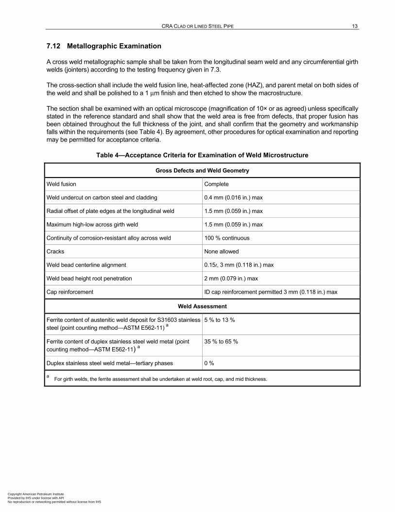
The section shall be examined with an optical microscope (magnification of 10× or as agreed) unless specifically stated in the reference standard and shall show that the weld area is free from defects, that proper fusion has been obtained throughout the full thickness of the joint, and shall confirm that the geometry and workmanship falls within the requirements (see Table 4). By agreement, other procedures for optical examination and reporting may be permitted for acceptance criteria.
Table 4—Acceptance Criteria for Examination of Weld Microstructure
Gross Defects and Weld Geometry
Weld fusion Complete
Weld undercut on carbon steel and cladding 0.4 mm (0.016 in.) max
Radial offset of plate edges at the longitudinal weld 1.5 mm (0.059 in.) max
Maximum high-low across girth weld 1.5 mm (0.059 in.) max
Continuity of corrosion-resistant alloy across weld 100 % continuous
Cracks None allowed
Weld bead centerline alignment 0.15t, 3 mm (0.118 in.) max
Weld bead height root penetration 2 mm (0.079 in.) max
Cap reinforcement ID cap reinforcement permitted 3 mm (0.118 in.) max
Weld Assessment
Ferrite content of austenitic weld deposit for S31603 stainless steel (point counting method—ASTM E562-11) a
5 % to 13 %
Ferrite content of duplex stainless steel weld metal (point counting method—ASTM E562-11) a
35 % to 65 %
Duplex stainless steel weld metal—tertiary phases 0 %
a For girth welds, the ferrite assessment shall be undertaken at weld root, cap, and mid thickness.
Copyright American Petroleum Institute Provided by IHS under license with API No reproduction or networking permitted without license from IHS
14 API SPECIFICATION 5LD
7.13 Hardness Test
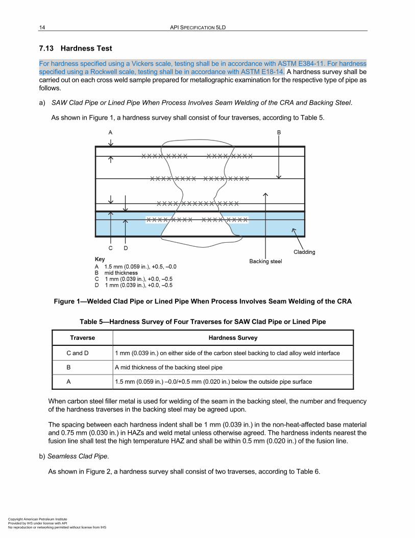
For hardness specified using a Vickers scale, testing shall be in accordance with ASTM E384-11. For hardness specified using a Rockwell scale, testing shall be in accordance with ASTM E18-14. A hardness survey shall be carried out on each cross weld sample prepared for metallographic examination for the respective type of pipe as follows.
a) SAW Clad Pipe or Lined Pipe When Process Involves Seam Welding of the CRA and Backing Steel.
As shown in Figure 1, a hardness survey shall consist of four traverses, according to Table 5.
Figure 1—Welded Clad Pipe or Lined Pipe When Process Involves Seam Welding of the CRA
Table 5—Hardness Survey of Four Traverses for SAW Clad Pipe or Lined Pipe
Traverse Hardness Survey
C and D 1 mm (0.039 in.) on either side of the carbon steel backing to clad alloy weld interface
B A mid thickness of the backing steel pipe
A 1.5 mm (0.059 in.) –0.0/+0.5 mm (0.020 in.) below the outside pipe surface
When carbon steel filler metal is used for welding of the seam in the backing steel, the number and frequency of the hardness traverses in the backing steel may be agreed upon.
The spacing between each hardness indent shall be 1 mm (0.039 in.) in the non-heat-affected base material and 0.75 mm (0.030 in.) in HAZs and weld metal unless otherwise agreed. The hardness indents nearest the fusion line shall test the high temperature HAZ and shall be within 0.5 mm (0.020 in.) of the fusion line.
b) Seamless Clad Pipe.
As shown in Figure 2, a hardness survey shall consist of two traverses, according to Table 6.
Copyright American Petroleum Institute Provided by IHS under license with API No reproduction or networking permitted without license from IHS

CRA CLAD OR LINED STEEL PIPE 15
Figure 2—Seamless Clad Pipe
Table 6—Hardness Survey of Two Traverses for Seamless Clad Pipe
Traverse Hardness Survey
C and D 1 mm (0.039 in.) on either side of the carbon steel base metal to clad alloy weld interface
No individual value in the backing steel material shall exceed 248 HV10 unless otherwise agreed upon according to Table 7.
Table 7—Hardness Test Requirements
Ferritic Steel Base Metal 248 HV10 at All Locations Unless Otherwise Agreed
Austenitic stainless steels 300 HV10 in all locations
22 % duplex stainless steel 300 HV10 in the parent material and 334 HV10 in the weld and HAZ
25 % duplex stainless super duplex steels 300 HV10 in the parent material and 378 HV10 in the weld and HAZ
Nickel base alloys (except those applied by explosion welding), e.g. Alloy 825 (LC2242) Alloy 625 (LC2262)
345 HV10 in all locations
Nickel base alloys applied by explosion welding e.g. Alloy 825 (LC2242) Alloy 625 (LC2262)
345 HV10 in all locations, except 40 HRC for explosion welded, cold work induced hardness per ANSI/NACE MR0175/ISO 15156-3:2009(E)
NOTE 1 For testing standard, refer to 7.13.
NOTE 2 The conversion factors between HV and other hardness values for stainless steels and nonferrous alloy do not correspond to those used for carbon steels.
Copyright American Petroleum Institute Provided by IHS under license with API No reproduction or networking permitted without license from IHS

16 API SPECIFICATION 5LD
If any result exceeds the applicable limit, the result shall be reported to the purchaser and two additional sections shall be cut from the same weld for testing. If either of these samples results in hardness values in excess of the above limits, these pipe shall be rejected and all pipes from that heat shall be rejected or individually tested.
8 Special Tests
8.1 Ferrite/Austenite Ratio for Duplex Stainless Steel
When the CRA layer is composed of duplex stainless steel, the ferrite/austenite ratio shall be measured. The requirements of API 5LC (4th Ed.), Section 8.1 shall apply for test methods, test frequency, and acceptance requirements. If this test has been performed on CRA tubes used for liner pipe as part of the specification for that material and the results are documented, there is no need to repeat the test for conformance to this standard.
8.2 Corrosion Testing
The purpose of corrosion testing is to assure proper manufacturing procedures for austenitic steel and Ni base alloys. It is not a test to determine susceptibility for use with a particular environment. A corrosion sensitivity test shall be performed as a manufacturing procedure qualification test (MPQT) on the CRA layers of austenitic steel and Ni base alloy as described below.
a) Summary of Test Procedure. The testing procedure shall conform to the requirements of the latest editions of ASTM A262-13, Practice B or Practice E, or ASTM G28-02, Method A, or ASTM G48-11, Method A (Section 8), whichever is suitable for the cladding or liner material and as agreed between the purchaser and manufacturer. The method that is used shall be agreed to between the purchaser and the manufacturer. Other practices may be agreed upon.
b) Specimen Sampling. One specimen shall be taken from the CRA layer of as manufactured pipe in the same condition as pipes to be delivered. For welded clad pipe and welded liner pipe of lined pipe, an additional specimen shall be taken from across the longitudinal weld (i.e. original CRA cladding + weld seam). The specimen axis shall be transverse to the pipe axis. One test for each heat or each heat-treatment lot shall be performed as described in the footnote to API 5LC (4th Ed.), Table 8.
As part of the MPQT, a parallel specimen shall be tested with a sample of the same CRA that has been deliberately sensitized in order to demonstrate that the chosen test method is capable of detection of a microstructure that is sensitive to intergranular corrosion. The sensitizing heat treatment shall be agreed upon between the purchaser and the manufacturer.
c) Specimen Preparation. The specimen shall be made of CRA layer and be approximately 76.2 mm (3 in.) long and 25.4 mm (1 in.) wide. Detailed sampling condition may be specified in the agreement between the purchaser and the manufacturer. Sawing is preferred to shearing; but if sheared, the sheared edge of the specimen shall be machined or ground-off. The specimen shall be tested in the as-received condition except that it may be flattened, if desired. Any scale on the specimen shall be removed mechanically with 120 grit iron-free aluminum oxide abrasive. Alternatively, chemical removal of scale is permissible. Each specimen shall be degreased using acetone, alcohol, or a vapor degreaser prior to testing.
d) Test Condition. The test solution and testing conditions shall be as stated in ASTM A262-13, ASTM G28-02, or ASTM G48-11 for the specific practice being conducted.
1) ASTM A262-13, Practice E, Bend Test. For acceptance, the tested specimen shall be bent through 180° over a diameter equal to twice the thickness of the specimen. Bending axis shall be perpendicular to the direction of the test specimen. Unless otherwise specified, the bend test system shall be a root bend (i.e. the inside surface of the pipe shall be strained in tension). The wall thickness need not be greater than 9.53 mm (0.375 in.).
Copyright American Petroleum Institute Provided by IHS under license with API No reproduction or networking permitted without license from IHS

CRA CLAD OR LINED STEEL PIPE 17
In case of material having low ductility, the maximum angle of bend without causing cracks in the material shall be determined by bending an untested specimen of the same configuration as the specimen to be tested. For welded specimens, the fusion line shall be located approximately at the centerline of the bend.
Minimum Acceptance Criteria. The bent test specimen shall first be examined at low magnification. If the evaluation is questionable, the specimen shall then be examined at a magnification of ×100. No cracking is permitted. An investigation to determine cause of failure is required and agreement by the purchaser is required prior to any retest procedure.
2) ASTM G28-02 or ASTM G48-11, Practice A—Minimum Acceptance Criteria. The acceptance criteria shall be agreed upon between the purchaser and the manufacturer. See ASTM G28-02, Paragraphs 8.2 and 8.3 or ASTM G48-11, Paragraph 8.0 for guidance.
8.3 Tests for CRA Cladding Bond Strength and CRA Liner Tightness
Tests for CRA cladding, bond strength, and CRA liner tightness are as follows.
a) Clad Steel Pipe. Special bond shear strength tests shall be performed. Typical tests for bond shear strength include those found in ASTM A264-12 and ASTM A265-12. Selection of the test method shall be by agreement. The test shall be carried out on one per 50 pipes during the manufacturing process. The minimum acceptable bond shear strength shall be 137.8 MPa (20,000 psi).
As an alternate to the bond shear strength and by agreement between the purchaser and the manufacturer, a flattening test may be conducted. Acceptance limit of clad separation or crack length shall be specified by agreement between the purchaser and manufacturer.
b) Lined Steel Pipe. The gripping force (σy) to determine the tightness between the lining and the backing steel shall be measured. The method of measurement shall be by agreement between purchaser and manufacturer. The gripping force (σy) shall be measured on one pipe during the MPQT and on one for every 50 pipes during production.
NOTE If the pipe is subsequently coated, heating during the coating process may affect the gripping force (σy).
The measured minimum force shall be by agreement between the purchaser and the manufacturer.
An example of a gripping force (σy) test is the residual compressive stress test method, and it is conducted as follows.
Two to four biaxial strain gauges are placed on the inside surface of the CRA layer of a short ring cut from the lined pipe. The CRA layer is taken out of the base material pipe by saw-cutting the base material pipe. The change in hoop strains and axial strains before and after take-out of the CRA layer are measured. Gripping force (σy) is calculated as the average value.
Gripping force (σy) in the circumferential direction is determined by using Equation (3) below:
( )Eσ νν
ε ε= + η η −
y xy
21 (3)
where
σy is the gripping force;
E is Young’s modulus of CRA layer (see Table 8);
Copyright American Petroleum Institute Provided by IHS under license with API No reproduction or networking permitted without license from IHS

18 API SPECIFICATION 5LD
ν is Poisson’s ratio of CRA layer (see Table 8);
η is the number of strain gauges;
εy is the strain in the circumferential direction;
εx is the strain in the longitudinal direction.
Other tests may be proposed and agreed upon between the purchaser and manufacturer.
Table 8—Young’s Modulus and Poisson’s Ratio at 25 °C (77 °F)
Alloy Young’s Modulus(103 ksi) Poisson’s Ratio
LC 1812 28 0.30
LC 2205 28 0.29
LC 2505 30 0.29
LC 2242 28 0.31
LC 2262 30 0.31
N08825 28 0.29
N06625 30 0.28
N10276 31 0.33
8.4 Residual Magnetism
The residual magnetism shall be recorded at both ends of each finished pipe and shall not exceed 15 Gauss. Magnetism levels higher than this value shall require the pipe end to be demagnetized until the level is reduced below 15 Gauss.
9 Hydrostatic Tests⎯Inspection Hydrostatic Test
9.1 Hydrostatic testing shall be in accordance with API 5L unless modified herein.
9.2 All pipe shall be tested after cladding or lining, heat treatment, expansion, and straightening.
9.3 Each length of pipe shall withstand, without leakage, a hoop stress equal to 95 % of specified minimum yield strength (SMYS) of the backing steel calculated on the basis of the minimum wall thickness of the backing steel. During the test, the pressure shall not be permitted to exceed the minimum test pressure by more than 5 %.
9.4 The minimum holding time for all sizes shall be 10 seconds following stabilization of the pressure.
9.5 In the case of lined pipe where the manufacturer can demonstrate that the pipe manufacturing method has already subjected the full pipe length to a hydrostatic stress higher than the calculated hydrostatic test pressure, then the hydrostatic test may be waived by agreement.
Copyright American Petroleum Institute Provided by IHS under license with API No reproduction or networking permitted without license from IHS

CRA CLAD OR LINED STEEL PIPE 19
10 Dimensions, Weights, and Lengths
10.1 Dimension and Weights
Line pipe shall be furnished in the backing steel material sizes and wall thicknesses provided in API 5L (45th Ed.), Table 9 or as specified on the purchase order.
The plain-end weight, wpe, shall be calculated using Equations (4) or (5) below:
In U.S. customary (USC) units:
( ) ( ) ( ) ( ) ( )w . D T T . D T t t F = − + − − pe 10 68 10 68 2 (4)
In SI units:
( ) ( ) ( ) ( ) ( )w . D T T . D T t t F = − + − − pe 0 02466 0 02466 2 (5)
where
wpe is the plain-end weight, rounded to the nearest 0.01 kg/m (0.01 lb/ft);
D is the outside diameter, rounded to the nearest 0.1 mm (0.001 in.) for sizes less than 457 mm (18 in.), and 1 mm (0.039 in.) for sizes 457 mm (18 in.) and larger;
T is the specified wall thickness of base material, rounded to the nearest 0.1 mm (0.001 in.);
t is the specified wall thickness of CRA layer, rounded to the nearest 0.1 mm (0.001 in.);
F is the correction factor for CRA materials (see Table 9).
Table 9—Correction Factors
Alloy Material Correction Factor, F
1812 1.017
2205 0.995
2506 0.995
2242 1.038
2262 1.075
NOTE The correction factor for CRA cladding or lined grades not listed in Table 9 is subject to agreement between the purchaser and manufacturer.
10.2 Diameter
The outside diameter of the final product shall be within the tolerances specified in Table 10. Inside diameters are governed by the outside diameter, wall, and CRA layer tolerances. Pipe with outside diameters intermediate to those listed in API 5L (45th Ed.), Table 9 may be supplied by agreement between the purchaser and the manufacturer. Such pipe shall be consistent with all requirements of this specification and shall be marked in accordance with Section 13.
Copyright American Petroleum Institute Provided by IHS under license with API No reproduction or networking permitted without license from IHS

20 API SPECIFICATION 5LD
As an alternate, when agreed upon between the purchaser and the manufacturer, pipe sizes may be furnished based upon an inside diameter.
The diameter tolerances at pipe ends shall apply to the nominal internal diameter. Tolerances on internal diameter are as indicated in Table 10.
10.3 Wall Thickness
Each length of finished pipe shall be measured for conformance to wall thickness and CRA layer requirements. The wall thickness at any place shall conform to the tolerances specified in Table 6. Wall thickness measurements shall be made with a properly calibrated nondestructive inspection device of appropriate accuracy. A typical method may be to measure the total thickness in clad pipe and the backing steel thickness in lined pipe with an ultrasonic straight beam device and to measure the cladding or liner with an electromagnetic method in accordance with ASTM B499. Or as an alternative, mechanical calipers may be used by agreement. Pipe with wall thicknesses intermediate to those listed in API 5L (45th Ed.), Table 9 may be supplied by agreement between the purchaser and manufacturer. Such pipe shall be consistent with all requirements of this specification and shall be marked in accordance with Section 13.
For pipe 114.3 mm (4.5 in.) OD and larger, the outside diameter measurements on the body of the pipe shall be made at the mill with a diameter tape on a random basis, but no less than three measurements per 8 hour working shift.
10.4 Mass
The tolerances for mass shall be as required by API 5L (45th Ed.), Section 9.14.
10.5 Length
Unless otherwise agreed upon between the purchaser and the manufacturer, pipe shall be furnished in the lengths shown in API 5L (45th Ed.), Table 12 or as specified on the purchase order.
The accuracy of length measuring devices for lengths of pipe less than 30 m (100 ft) shall be ±0.03 m (0.1 ft).
10.6 Straightness
Pipe shall be reasonably straight. All pipe shall be checked at two or more circumferential positions for straightness, and deviation from a straight line shall not exceed 0.2 % of the length. Measurements may be made using a taut string or wire from end-to-end along the side of the pipe, measuring the greatest deviation between the string or wire and the pipe.
10.7 Jointers
When specified on the purchase order and by agreement, jointers (two lengths of pipe welded together to make a standard length) of clad pipe may be furnished with the seam welds displaced between 45° and 90°. Details of procedures and tests required for furnishing such jointers shall be by as specified in Annex E. Jointers in lined pipe are not permitted unless specifically agreed upon between the purchaser and the manufacturer. When jointers are supplied, the straightness measured according to the procedure stated in 10.6 shall be agreed upon between the manufacturer and the purchaser. Jointers shall meet the straightness criterion in 10.6.
Copyright American Petroleum Institute Provided by IHS under license with API No reproduction or networking permitted without license from IHS

CRA CLAD OR LINED STEEL PIPE 21
Table 10—Tolerances on Dimensions and Weights
Diameter Out-of-roundness
Pipe Body The pipe body outside diameter shall be controlled to a tolerance of ±0.75 % for seamless pipe; and +0.75 %, –0.25 % for welded pipe with a maximum deviation from the nominal OD of ±3.2 mm (0.125 in.)
Pipe Body Out-of-roundness for pipe body shall not exceed 1.5 % D [max 10 mm (0.394 in.)]
Pipe Ends The tolerance on the inside diameter for distance of 100 mm (4 in.) from the end of the pipe shall be ±1.0 %
Pipe Ends Out-of-roundness of pipe ends [100 mm (4 in.)] shall not exceed 1.0 % D [max 5mm (0.196 in.)] of nominal OD
Pipe Body and Ends Local irregularity of inside surface shall be less than 0.5 % D[max 2 mm (0.079 in.)] measured by internal radius gauge encompassing a 200 mm (8 in.) length of arc
Wall Thickness Tolerance
Backing Steel See API 5L (45th Ed.), Table 11 a
CRA Layer –0, +2 mm (0.079 in.)
Weight Tolerances
See API 5L (45th Ed.), Section 9.14.
Change weight to mass per API 5L (45th Ed.), Section 9.11.2.
a For clad pipe, a higher positive tolerance may be agreed between purchaser and manufacturer. The negative tolerance shall always be maintained.
10.8 Pipe Ends
10.8.1 Bevels. Unless otherwise ordered, plain-end pipe in sizes 60.3 mm (2.375 in.) and larger shall be furnished with ends beveled to an angle of 30°, +5°, –0°, measured from a line drawn perpendicular to the axis of the pipe, and with a root face of 1.59 mm ± 0.79 mm (0.0625 in. ± 0.0312 in.).
The end finish for pipe in sizes smaller than 60.3 mm (2.375 in.) shall be as specified on the purchase order.
10.8.2 Lined Pipe End Seal Weld. Unless agreed upon between the purchaser and the manufacturer a seal weld shall be made between the lining and the backing steel. A procedure for making and testing to the requirements of 11.3.3 and 11.3.4. This welding procedure shall be submitted as part of the qualification documents (see Section 14).
11 Nondestructive Inspection
11.1 Inspection Methods for Welded Clad Pipe
11.1.1 The weld seam of welded clad pipe shall be inspected full length (100 %) by radiological methods in accordance with API 5L (45th Ed.), E.4 or by manual or automatic ultrasonic testing (UT) procedures or as agreed upon by the purchaser and the manufacturer. An ultrasonic inspection shall be performed for disbondment of the cladding, as defined in ASTM A263-12, A264-12, and A265-12, Section 13, along the zone
Copyright American Petroleum Institute Provided by IHS under license with API No reproduction or networking permitted without license from IHS

22 API SPECIFICATION 5LD
50 mm (2 in.) on each side of the weld seam. The inspection requirements of API 5L (45th Ed.) shall apply where applicable unless otherwise supplemented by this specification.
11.1.2 Clad plate for welded clad pipe shall be inspected prior to forming according to the requirements of ASTM A578-07. Scanning coverage defined in ASTM A578-07, Paragraph 5.6.1 shall be amended to include scanning along a continuous grid on 1 in. centers. Acceptance criteria shall meet Level C as stated in ASTM A578-07.
11.1.3 The ends of clad pipe shall be inspected by UT for a distance of 100 mm (4 in.) for disbonding. The requirements of API 5L (45th Ed.), E.3.2 and E.3.3 shall apply.
11.2 Inspection Methods for Seamless Clad Pipe
Seamless pipe shall be inspected full length by ultrasonic methods using procedures capable of locating defects within the backing steel or the cladding. Both shear wave for radial or through wall defects and compression wave for laminar defects at the bond line techniques shall be used. The acceptance criteria for backing steel shall be according to API 5L (45th Ed.), E.8. The acceptance criteria for the bond line shall be according to ASTM A578-07, Level C. Scanning coverage shall be along 1 in. centers along the entire length of the pipe. The location of the equipment shall be at the discretion of the manufacturer; however, the nondestructive inspection shall take place after all heat-treating and expansion operations, if performed, but may take place before cropping, beveling, and end sizing.
11.3 Inspection Methods for Lined Pipe
11.3.1 Both the backing steel and the CRA layer of the lined pipe shall be inspected. The inspection shall be made before lining and following all manufacturing steps and hydrotest unless otherwise agreed between the purchaser and the manufacturer. This inspection shall be capable of discovering defects in the full volume of the backing steel and the CRA lining. The requirements of API 5L (45th Ed.), Annex E and API 5LC (4th Ed.), Section 11 shall apply.
11.3.2 Weld seams in the backing steel, or lining, whichever is applicable, shall meet the same inspection acceptance criteria as the pipe specification [i.e. API 5L (45th Ed.) or API 5LC (4th Ed.) for the backing steel and liner materials, respectively]. This inspection shall be made following all manufacturing steps and hydrotest and shall be made before lining of lined pipe unless otherwise agreed. In addition to the weld seam inspection, the inner CRA surface shall be inspected by electromagnetic inspection in accordance with API 5LC (4th Ed.), Sections 11.15 and 11.16. For sizes greater than 168.3 mm (6.625 in.), ASTM E426 or ISO 10893-2 may be used by agreement. Alternative inspections for the liner shall be agreed between the manufacturer and the purchaser.
11.3.3 Visual examination and dye penetrant inspection shall be carried out on the full circumference of all seal welds between the liner and backing steel according to ASTM E165-12. Acceptance criteria for all inspections of the seal welds shall be agreed upon between the manufacturer and the purchaser.
If agreed, weld overlaying of the ends may be performed in place of seal welding. In this case, all of the requirements for weld overlaying in this standard shall be met.
11.3.4 The first 10 seal welds completed during each production run and one in every 20 thereafter shall be fully radiographed. As an alternative, and if agreed, the automatic UT inspection may be used instead of radiography. Acceptance criteria for all inspection of the seal weld shall be agreed upon between the manufacturer and the purchaser. If unacceptable defects are found in any of the seal welds subjected to examination the inspection level shall revert to 100 % inspection until 20 consecutive defect free welds have been produced. The welds between the one which failed inspection and the 20 previous welds shall be inspected.
11.3.5 Inspection of Liner Interface. The lining of lined pipe shall be inspected for tightness using an appropriate method agreed to between the purchaser and the manufacturer. Acceptance criteria shall likewise be agreed.
Copyright American Petroleum Institute Provided by IHS under license with API No reproduction or networking permitted without license from IHS
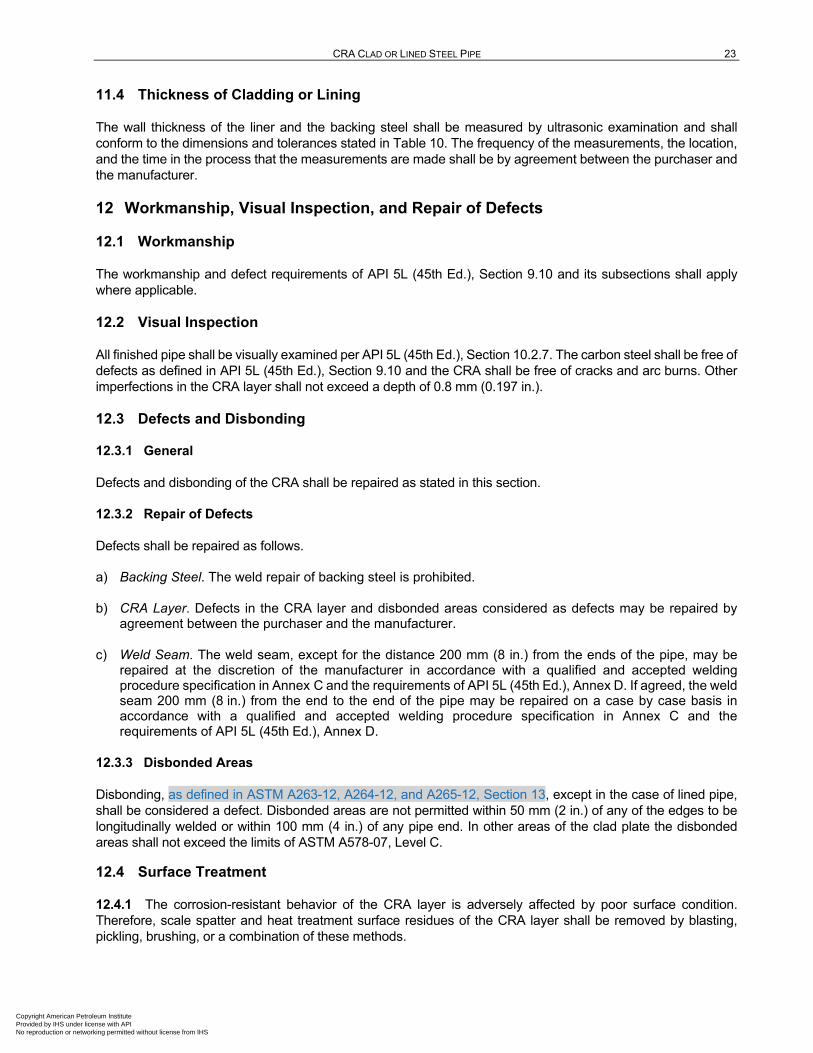
CRA CLAD OR LINED STEEL PIPE 23
11.4 Thickness of Cladding or Lining
The wall thickness of the liner and the backing steel shall be measured by ultrasonic examination and shall conform to the dimensions and tolerances stated in Table 10. The frequency of the measurements, the location, and the time in the process that the measurements are made shall be by agreement between the purchaser and the manufacturer.
12 Workmanship, Visual Inspection, and Repair of Defects
12.1 Workmanship
The workmanship and defect requirements of API 5L (45th Ed.), Section 9.10 and its subsections shall apply where applicable.
12.2 Visual Inspection
All finished pipe shall be visually examined per API 5L (45th Ed.), Section 10.2.7. The carbon steel shall be free of defects as defined in API 5L (45th Ed.), Section 9.10 and the CRA shall be free of cracks and arc burns. Other imperfections in the CRA layer shall not exceed a depth of 0.8 mm (0.197 in.).
12.3 Defects and Disbonding
General 12.3.1
Defects and disbonding of the CRA shall be repaired as stated in this section.
Repair of Defects 12.3.2
Defects shall be repaired as follows.
a) Backing Steel. The weld repair of backing steel is prohibited.
b) CRA Layer. Defects in the CRA layer and disbonded areas considered as defects may be repaired by agreement between the purchaser and the manufacturer.
c) Weld Seam. The weld seam, except for the distance 200 mm (8 in.) from the ends of the pipe, may be repaired at the discretion of the manufacturer in accordance with a qualified and accepted welding procedure specification in Annex C and the requirements of API 5L (45th Ed.), Annex D. If agreed, the weld seam 200 mm (8 in.) from the end to the end of the pipe may be repaired on a case by case basis in accordance with a qualified and accepted welding procedure specification in Annex C and the requirements of API 5L (45th Ed.), Annex D.
Disbonded Areas 12.3.3
Disbonding, as defined in ASTM A263-12, A264-12, and A265-12, Section 13, except in the case of lined pipe, shall be considered a defect. Disbonded areas are not permitted within 50 mm (2 in.) of any of the edges to be longitudinally welded or within 100 mm (4 in.) of any pipe end. In other areas of the clad plate the disbonded areas shall not exceed the limits of ASTM A578-07, Level C.
12.4 Surface Treatment
12.4.1 The corrosion-resistant behavior of the CRA layer is adversely affected by poor surface condition. Therefore, scale spatter and heat treatment surface residues of the CRA layer shall be removed by blasting, pickling, brushing, or a combination of these methods.
Copyright American Petroleum Institute Provided by IHS under license with API No reproduction or networking permitted without license from IHS

24 API SPECIFICATION 5LD
All pipes shall be delivered with clean external and internal surfaces. Cleaning of the CRA should include, but not be restricted to, the following sequence:
a) degreasing (for cold hardened product);
b) washing in water;
c) acid pickling or acid cleaning; and
d) final washing in clean water with chloride ion content (mass fraction) of less than 200 mg/l.
NOTE At low concentrations, “mg/l” is approximately equivalent to the deprecated term “ppm.”
At the end of the cycle, the pipe shall be completely dry.
12.4.2 Pipe shall be clean and dry before shipping. End protectors that prevent buildup of moisture in the pipe are recommended.
13 Marking
13.1 General
Pipe manufactured in conformance with this specification shall be marked by the manufacturer as follows:
a) the required marking on pipe shall be as stipulated in API 5L (45th Ed.), Section 11 and its subsections and as required below;
b) no markings shall be made on the cladding or lining on the inside of the pipe.
13.2 Sequence of Markings
Pipe manufactured according to this standard shall be marked as follows.
a) Manufacturer’s Name or Mark.
b) Spec 5LD. “Spec 5LD” shall be paint stenciled when the product is in complete compliance with this specification.
c) Sizes. The outside diameter followed by the nominal wall thickness of backing steel and CRA layer.
d) Weight per Foot. For sizes 114.3 mm (4.5 in.) and larger, the calculated weight or mass using the equation in API 5L (45th Ed.).
e) Grade and CRA. The symbols to be used are as follows:
Yield Strength of Backing Steel X
CRA Grade LC number or grade number in Table 3
f) Process of Manufacture of Backing Steel and CRA Layer. The symbols to be used are as follows:
Clad Pipe Lined Pipe
Seamless S Seamless SL
Welded E Welded EL
Copyright American Petroleum Institute Provided by IHS under license with API No reproduction or networking permitted without license from IHS

CRA CLAD OR LINED STEEL PIPE 25
g) Heat Treatment. The symbols to be used are as follows:
Normalized N
As-rolled R
Quench and Tempered Q
Solution Annealed H
Thermomechanically Rolled or Formed M
h) Hydrostatic Test Pressure. The test pressure in psi or MPa, preceded by the word “TESTED,” shall be paint stenciled.
i) The unique pipe number shall be die stamped on the end bevel or surface of each pipe and be traceable to the heat number of the backing steel and the CRA layer or liner. If the pipe is too thin to allow this stamping, an alternative method may be agreed on between the purchaser and the manufacturer. The system for designating these numbers shall be by agreement between the purchaser and the manufacturer.
EXAMPLE
USC units:
Seamless lined pipe 14 in. OD, 0.375 in. backing steel wall thickness, 0.125 in. CRA layer thickness, Grade X70M, LC 30-1812 CRA lined, solution annealed, tested at 3190 psi from manufacturer ABCO also meeting requirements of API 5L (45th Ed.), Annex G and Annex J shall be stenciled as follows:
ABCO Spec 5LD 14 0 0.375/0.125
71.68 X70M SL/LC 1812 SLH 3190psi G J
NOTE The weight per foot (71.68 lb/ft) is computed by the equations in 10.1.
SI units:
Seamless lined pipe 355.6 mm OD, 9.5 mm backing steel wall thickness, 3.2 mm CRA layer thickness. Grade L485M SAWL backing steel, LC 30-1812 CRA lined, solution annealed, test at 20.7 MPa from manufacturer ABCO shall be stenciled as follows:
ABCO Spec 5LD 355.6 9.5/3.2
81.08 L485M SL/LC 1812 SLH 20.7 MPa
13.3 Pipe Processor Markings
Pipe heat treated by a processor other than the manufacturer shall be marked as stipulated in 13.1 and 13.2. The processor shall remove any identity which is not indicative of the new condition of the product as a result of heat treating (i.e. prior grade identity, original pipe manufacturer’s name or logo).
Copyright American Petroleum Institute Provided by IHS under license with API No reproduction or networking permitted without license from IHS

26 API SPECIFICATION 5LD
14 Documentation
14.1 Certification
The manufacturer shall as a minimum, furnish to the purchaser a certificate of compliance stating that the material has been manufactured, sampled, tested, and inspected in accordance with this specification and has been found to meet the requirements.
14.2 Electronic Certificate of Compliance
A material test report, certificate of compliance, or similar document printed or used in electronic form from an electronic data interchange (EDI) transmission shall be regarded as having the same validity as a counterpart printed in the certifier’s facility. The content of the EDI transmitted document shall meet the requirements of this specification and conform to any existing EDI agreement between the purchaser and the supplier.
Copyright American Petroleum Institute Provided by IHS under license with API No reproduction or networking permitted without license from IHS

27
Annex A (informative)
API Monogram Program Use of the API Monogram by Licensees
A.1 Scope
A.1.1 Applicability
This annex is normative (mandatory) for products supplied bearing the API Monogram and manufactured at a facility licensed by API; for all other instances it is not applicable.
A.1.2 General
The API Monogram® is a registered certification mark owned by the American Petroleum Institute (API) and authorized for licensing by the API Board of Directors. Through the API Monogram Program, API licenses product manufacturers to apply the API Monogram to products which comply with product specifications and have been manufactured under a quality management system that meets the requirements of API Q1. API maintains a complete, searchable list of all Monogram licensees on the API Composite List website (www.api.org/compositelist).
The application of the API Monogram and license number on products constitutes a representation and warranty by the licensee to API and to purchasers of the products that, as of the date indicated, the products were manufactured under a quality management system conforming to the requirements of API Q1 and that the product conforms in every detail with the applicable standard(s) or product specification(s). API Monogram program licenses are issued only after an on-site audit has verified that an organization has implemented and continually maintained a quality management system that meets the requirements of API Q1 and that the resulting products satisfy the requirements of the applicable API product specification(s) and/or standard(s). Although any manufacturer may claim that its products meet API product requirements without monogramming them, only manufacturers with a license from API can apply the API Monogram to their products.
Together with the requirements of the API Monogram license agreement, this annex establishes the requirements for those organizations who wish to voluntarily obtain an API license to provide API monogrammed products that satisfy the requirements of the applicable API product specification(s) and/or standard(s) and API Monogram Program requirements.
For information on becoming an API Monogram Licensee, please contact API, Certification Programs, 1220 L Street, NW, Washington, DC 20005 or call (202) 682-8145 or by email at [email protected].
A.2 Normative References
In addition to the referenced standards listed earlier in this document, this annex references the following standard:
API Specification Q1, Specification for Quality Management System Requirements for Manufacturing Organizations for the Petroleum and Natural Gas Industry
For Licensees under the Monogram Program, the latest version of this document shall be used. The requirements identified therein are mandatory.
Copyright American Petroleum Institute Provided by IHS under license with API No reproduction or networking permitted without license from IHS

28 API SPECIFICATION 5LD
A.3 API Monogram Program: Licensee Responsibilities
A.3.1 Monogram Program Requirements
For all organizations desiring to acquire and maintain a license to use the API Monogram, conformance with the following shall be required at all times:
a) quality management system requirements of API Q1;
b) API Monogram Program requirements of API Q1, Annex A;
c) requirements contained in the API product specification(s) to which the organization is licensed; and
d) requirements contained in the API Monogram Program License Agreement.
A.3.2 Control of the Application and Removal of the API Monogram
Each licensee shall control the application and removal of the API Monogram in accordance with the following:
a) products that do not conform to API specified requirements shall not bear the API Monogram;
b) each licensee shall develop and maintain an API Monogram marking procedure that documents the marking/monogramming requirements specified by this annex and any applicable API product specification(s) and/or standard(s). The marking procedure shall:
1) define the authority responsible for application and removal of the API Monogram and license number;
2) define the method(s) used to apply the Monogram and license number;
3) identify the location on the product where the API Monogram and license number are to be applied;
4) require the application of the date of manufacture of the product in conjunction with the use of the API Monogram and license number;
5) require that the date of manufacture, at a minimum, be two digits representing the month and two digits representing the year (e.g. 05-12 for May 2012) unless otherwise stipulated in the applicable API product specification(s) or standard(s); and
6) define the application of all other required API product specification(s) and/or standard(s) marking requirements.
c) only an API licensee shall apply the API Monogram and its designated license number to API monogrammable products;
d) the API Monogram and license number, when issued, are site-specific and subsequently the API Monogram shall only be applied at that site specific licensed facility location; and
e) the API Monogram may be applied at any time appropriate during the production process but shall be removed in accordance with the licensee’s API Monogram marking procedure if the product is subsequently found to be out of conformance with any of the requirements of the applicable API product specification(s) and/or standard(s) and API Monogram Program.
For certain manufacturing processes or types of products, alternative API Monogram marking procedures may be acceptable. Requirements for alternative API Monogram marking are detailed in the, API Monogram
Copyright American Petroleum Institute Provided by IHS under license with API No reproduction or networking permitted without license from IHS
CRA CLAD OR LINED STEEL PIPE 29
Program Alternative Marking of Products License Agreement, available on the API Monogram Program website at http://www.api.org/alternative-marking.
A.3.3 Design and Design Documentation
Each licensee and/or applicant for licensing shall maintain current design documentation as identified in API Q1 for all of the applicable products that fall under the scope of each Monogram license. The design document information shall provide objective evidence that the product design meets the requirements of the applicable and most current API product specification(s) and/or standard(s). The design documentation shall be made available during API audits of the facility.
In specific instances, the exclusion of design activities is allowed under the Monogram Program, as detailed in Advisory #6, available on API Monogram Program website at http://www.api.org/advisories.
A.3.4 Manufacturing Capability
The API Monogram Program is designed to identify facilities that have demonstrated the ability to manufacture equipment that conforms to API specifications and/or standards. API may refuse initial licensing or suspend current licensing based on a facility’s level of manufacturing capability. If API determines that an additional review is warranted, API may perform additional audits (at the organization’s expense) of any subcontractors to ensure their conformance with the requirements of the applicable API product specification(s) and/or standard(s).
A.3.5 Use of the API Monogram in Advertising
An API Monogram licensee shall not use the API Monogram and/or license number on letterheads, buildings or other structures, websites or in any advertising without an express statement of fact describing the scope of Licensee’s authorization (license number and product specification). The Licensee should contact API for guidance on the use of the API Monogram other than on products.
A.4 Product Marking Requirements
A.4.1 General
These marking requirements shall apply only to those API Licensees wishing to mark applicable products in conjunction with the requirements of the API Monogram Program.
A.4.2 Product Specification Identification
Manufacturers shall mark products as specified by the applicable API specifications or standards. Marking shall include reference to the applicable API specification and/or standard. Unless otherwise specified, reference to the API specifications and/or standards shall be, as a minimum, “API [Document Number]” (e.g. API 6A or API 600). Unless otherwise specified, when space allows, the marking may include use of “Spec” or “Std”, as applicable (e.g. API Spec 6A or API Std 600).
A.4.3 Units
Products shall be marked with units as specified in the API specification and/or standard. If not specified, equipment shall be marked with U.S. customary (USC) units. Use of dual units [USC units and metric (SI) units] may be acceptable, if such units are allowed by the applicable product specification and/or standard.
A.4.4 Nameplates
Nameplates, when applicable, shall be made of a corrosion-resistant material unless otherwise specified by the API specification and/or standard. Nameplate shall be located as specified by the API specification and/or
Copyright American Petroleum Institute Provided by IHS under license with API No reproduction or networking permitted without license from IHS

30 API SPECIFICATION 5LD
standard. If the location is not specified, then the licensee shall develop and maintain a procedure detailing the location to which the nameplate shall be applied. Nameplates may be attached at any time during the manufacturing process.
The API Monogram and license number shall be marked on the nameplate, in addition to the other product marking requirements specified by the applicable product specification and/or standard.
A.4.5 License Number
The API Monogram license number shall not be used unless it is marked in conjunction with the API Monogram. The license number shall be used in close proximity to the API Monogram.
A.5 API Monogram Program: Nonconformance Reporting
API solicits information on products that are found to be nonconforming with API specified requirements, as well as field failures (or malfunctions), which are judged to be caused by either specification and/or standard deficiencies or nonconformities against API specified requirements. Customers are requested to report to API all problems with API monogrammed products. A nonconformance may be reported using the API Nonconformance Reporting System available at http://compositelist.api.org/ncr.aspx.
Copyright American Petroleum Institute Provided by IHS under license with API No reproduction or networking permitted without license from IHS

31
Annex B (normative)
Manufacturing Procedure Specification
The manufacturing procedure specification (MPS) shall include procedures and operations that influence the quality and reliability of the final product.
B.1 The MPS may include, but should not necessarily be limited to, the following items.
a) Steelmaker and plants at which the carbon backing steel, CRA, and clad/lined pipe are to be produced.
b) Method of cladding or lining.
c) Reheating temperatures.
d) Heat treatment condition of rolled plates, if applicable.
e) Mother plate or clad plate UT techniques, coverage, and acceptance criteria.
f) Method of calibrating UT and frequency of calibrations.
g) Roughness of CRA surface.
h) Handling procedure for CRA at all manufacturing stages detailing precautions taken to avoid iron contamination (this could be a standalone procedure).
i) Method of forming pipe shape from plate or strip.
j) Method of tack welding and spacing of tack welds (if any).
k) Methods and stages of attaching and removing run-on and run-off plates.
l) Longitudinal weld welding procedure for backing steel and cladding or liner (including girth weld procedure, where applicable), including all welding parameters and existing procedure qualification test reports.
m) Methods of weld defect removal, repair welding procedures, and procedure qualification test reports.
n) Types, sizes, and brand names of all welding consumables.
o) For lined pipe:
1) pipe or plate drying and cleaning methods prior to assembly;
2) assembly technique;
3) method for pipe sizing;
4) method for assuring dimensional control;
5) method of gripping force measurement, if applicable;
6) pipe expansion and control methods to meet maximum allowable strain; and
Copyright American Petroleum Institute Provided by IHS under license with API No reproduction or networking permitted without license from IHS
32 API SPECIFICATION 5LD
7) seal welding detail and weld inspection procedures.
p) Pipe-end UT technique, with acceptance criteria.
q) Full details of UT equipment and techniques for the longitudinal weld, including a statement of the weld length at the pipe ends not scanned by all probes, frequency of calibration, and methods of marking defects and indicating loss of coupling.
r) Procedures/techniques for dry or wet MPI, including reference standards.
s) Method and frequency of calibrating pipe-end ultrasonic test equipment.
t) Method of measuring pipe wall thickness, including sensitivity and calibration technique.
u) Full details of radiographic testing equipment, including film type.
v) Methods for measuring and controlling the pipe-end internal diameter.
w) Techniques proposed for measuring end squareness and peaking at the weld.
x) Where seamless production is used, details of method of ensuring consistency of cladding layer thickness along pipe length and/or detailed past production experience.
y) Control and storage of welding consumables.
B.2 The attachments to the MPS should include, as applicable, the following procedures.
a) MPS for carbon steel plate and pipe.
b) Material traceability and identification through all manufacturing stages.
c) Quality control plan and process flow chart.
d) Welding consumable storage and handling procedure, including method employed for maintaining traceability.
e) Correction of pipe out of roundness.
f) Nondestructive testing procedures for each technique to be applied.
g) Seam welding and weld repair procedures and proposal for qualification.
h) Corrosion and iron contamination testing procedures.
i) Pipe handling and storage.
j) Ship, rail, or truck loading diagrams.
Copyright American Petroleum Institute Provided by IHS under license with API No reproduction or networking permitted without license from IHS
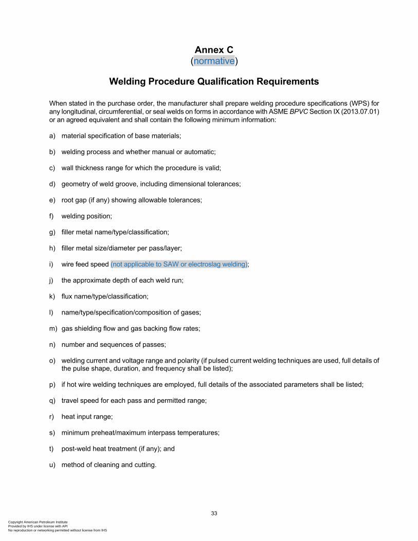
33
Annex C (normative)
Welding Procedure Qualification Requirements
When stated in the purchase order, the manufacturer shall prepare welding procedure specifications (WPS) for any longitudinal, circumferential, or seal welds on forms in accordance with ASME BPVC Section IX (2013.07.01) or an agreed equivalent and shall contain the following minimum information:
a) material specification of base materials;
b) welding process and whether manual or automatic;
c) wall thickness range for which the procedure is valid;
d) geometry of weld groove, including dimensional tolerances;
e) root gap (if any) showing allowable tolerances;
f) welding position;
g) filler metal name/type/classification;
h) filler metal size/diameter per pass/layer;
i) wire feed speed (not applicable to SAW or electroslag welding);
j) the approximate depth of each weld run;
k) flux name/type/classification;
l) name/type/specification/composition of gases;
m) gas shielding flow and gas backing flow rates;
n) number and sequences of passes;
o) welding current and voltage range and polarity (if pulsed current welding techniques are used, full details of the pulse shape, duration, and frequency shall be listed);
p) if hot wire welding techniques are employed, full details of the associated parameters shall be listed;
q) travel speed for each pass and permitted range;
r) heat input range;
s) minimum preheat/maximum interpass temperatures;
t) post-weld heat treatment (if any); and
u) method of cleaning and cutting.
Copyright American Petroleum Institute Provided by IHS under license with API No reproduction or networking permitted without license from IHS

34
Annex D (normative)
Manufacturing Procedure Qualification Test
This annex provides the requirements and procedures for performing a MPQT.
D.1 Frequency of Testing
At least one pipe of each size shall be manufactured in accordance with the agreed MPS and be subjected to all of the production inspection and testing required by this specification plus the additional testing defined below.
D.2 Scope of Testing
The following additional tests shall also be undertaken on the MPQT.
a) The welded seam shall be inspected by radiography for longitudinal and transverse defects along its full length, or by manual or automatic UT procedures, whichever is applicable for the production pipe, and assessed against the requirements of this specification.
b) MPI shall be performed on 100 % of the backing steel pipe OD surface of the external carbon steel weld seam.
c) The complete internal surface shall be visually inspected. For sizes less than 406.4 mm (16.000 in.), an endoscope or video camera shall be used unless other methods are available to perform this inspection.
d) An all-weld-metal (longitudinal) tensile test specimens shall be prepared from the longitudinal weld seam and, where practical, from any girth weld. The 0.2 % proof stress shall be measured and shall comply with the SMYS of the pipe.
e) The ultimate tensile strength, elongation, and reduction of area shall also be reported.
f) Where the maximum design temperature is above 100 °C (212 °F), transverse and longitudinal pipe body and all weld metal tensile tests should be carried out at the maximum design temperature. Refer to DNV FS 101, Section 5, Figure 2 for guidance.
g) Sets of weld metal and HAZ Charpy test pieces shall be taken from each end of the pipe. All test results shall meet the requirements of the pipeline datasheet and 7.11.3.
h) If agreed, additional Charpy tests on weld metal, HAZ, Fusion Line +2 mm (0.0787 in.), and pipe body shall be carried out at temperatures from –10 °C (approximately 15 °F) through –60 °C (approximately –75 °F) at 10 °C (approximately 15 °F) increments.
i) Shear area shall be recorded in all cases. This data shall be presented in the form of transition curves for both energy and shear area.
j) Macrosections for hardness tests shall be taken at approximately 2 m (78.74 in.) from each end of the pipe according to 7.12.
k) Where applicable, additional DWTTs in accordance with 7.11.4 to establish a transition curve with testing temperatures as defined above for Charpy tests.
l) Intergranular corrosion test according to 8.2.
Copyright American Petroleum Institute Provided by IHS under license with API No reproduction or networking permitted without license from IHS

CRA CLAD OR LINED STEEL PIPE 35
m) Test for bonding according to 8.3.
n) Test for continuity of cladding surface according to 12.2.
o) Where the pipeline service is defined as submarine, the pipe body Charpy test requirements of 7.11.3 shall be met on longitudinal test pieces taken from a section of the pipe after it has been machined flat and subjected to a 5 % tensile strain in the longitudinal direction, followed by a heat treatment of 1 hour at 280 °C ± 5 °C.
p) Load/displacement (stress/strain) curves that extend up to a minimum of 3 % displacement shall be supplied for base material and all-weld metal tensile specimens tested as part of MPS testing.
Copyright American Petroleum Institute Provided by IHS under license with API No reproduction or networking permitted without license from IHS

36
Annex E (normative)
Jointer Requirements
E.1 Where pipe is furnished with a girth weld, welding shall be in accordance with the requirements of this specification. The WPS shall incorporate all the welding parameters listed in Annex C.
E.2 The internal weld bead pass shall be made with a welding consumable which is over-alloyed, compared to the CRA layer.
E.3 Procedures shall be established for checking the cleanliness of the weld zone prior to welding, including the removal of any cutting debris from the bevel to ensure there is no iron contamination of the CRA surface.
E.4 The internal surface of the weld and HAZ should be protected from oxidation by provision of sufficient inert shielding gas flow. The finished weld surface should be bright in appearance with little or no “bluing.” There should not be any signs of blackening. The oxidation acceptance criteria are to be agreed to during welding procedure qualification (see Bibliographic Item [4] for guidance on acceptable oxidation levels). The surface of the finished weld should be examined visually or preferably with the aid of a camera to ensure correct protection has been achieved.
Alternatively, postwelding cleaning may be applied, such as pickling and passivation.
E.5 Welding procedure qualification tests shall include the testing required by ASME BPVC Section IX (2013.07.01) and the additional requirements defined in this specification.
Copyright American Petroleum Institute Provided by IHS under license with API No reproduction or networking permitted without license from IHS

37
Annex F (normative)
Purchaser Inspection
F.1 Inspection Notice Where the inspector representing the purchaser desires to inspect pipe or witness tests, reasonable notice shall be given of the time at which the run is to be made.
F.2 Inspection Location All inspections should be made at the place of manufacture prior to shipment unless otherwise specified on the purchase order and shall be so conducted as not to interfere unnecessarily with the operation of the works.
F.3 Compliance The manufacturer is responsible for complying with all of the provisions of this specification. The purchaser may conduct an investigation necessary to assure compliance by the manufacturer and may reject any material that does not comply with this specification.
F.4 Rejection Unless otherwise provided, material that shows defects upon inspection or subsequent to acceptance at the manufacturer’s works, or material that proves defective when properly applied in service, may be rejected and the manufacturer so notified. If tests that require the destruction of material are made, any product proven not to have met the requirements of the specification shall be rejected. Disposition of rejected product shall be a matter of agreement between the manufacturer and the purchaser.
Copyright American Petroleum Institute Provided by IHS under license with API No reproduction or networking permitted without license from IHS

38
Bibliography
[1] API Standard 1104, Welding Pipelines and Related Facilities, 21st Edition
[2] ASME Boiler and Pressure Vessel Code (BPVC) 7, Section V: Nondestructive Examination
[3] ASME BPVC, Section VIII: Pressure Vessels, Division 1: Para. UW-51
[4] ASME B31.3, Process Piping
[5] ASTM A370 8, Standard Test Methods and Definitions for Mechanical Testing of Steel Products
[6] ASTM B499, Standard Test Method for Measurement of Coating Thicknesses by the Magnetic Method: Nonmagnetic Coatings on Magnetic Basis Metals
[7] ASTM E426, Standard Practice for Electromagnetic (Eddy-Current) Examination of Seamless and Welded Tubular Products, Austenitic Stainless Steel and Similar Alloys
[8] ASTM E709, Standard Guide for Magnetic Particle Testing
[9] DNV OS F101 2012-08 9, Submarine Pipeline Systems
[10] ISO 3183 10, Petroleum and natural gas industries—Steel pipe for pipeline transportation systems
[11] ISO 10893-2, Non-destructive testing of steel tubes—Part 2: Automated eddy current testing of seamless and welded (except submerged arc-welded) steel tubes for the detection of imperfections
Smith L.M., and Klein M., “Acceptance Criteria for Oxidation of Stainless Steel Weldments,” Stainless Steel World, Vol. 8, Issue 10, December 1996
7 ASME International, 3 Park Avenue, New York, New York 10016, www.asme.org. 8 ASTM International, 100 Barr Harbor Drive, West Conshohocken, Pennsylvania 19428, www.astm.org. 9 DNV GL, Veritasveien 1, 1322 Hovik, Oslo, Norway, www.dnvgl.com. 10 International Organization for Standardization, 1, ch. de la Voie-Creuse, Case postale 56, CH-1211 Geneva 20,
Switzerland, www.iso.org.
Copyright American Petroleum Institute Provided by IHS under license with API No reproduction or networking permitted without license from IHS

Copyright American Petroleum Institute Provided by IHS under license with API No reproduction or networking permitted without license from IHS
Product No. G5LD04
Copyright American Petroleum Institute Provided by IHS under license with API No reproduction or networking permitted without license from IHS