
API - Solid Bed Adsorbers.pdf
71
SOLID BED DSORBERS
-
Upload
imtiaz-ali -
Category
Documents
-
view
216 -
download
0
Transcript of API - Solid Bed Adsorbers.pdf

8/14/2019 API - Solid Bed Adsorbers.pdf
http://slidepdf.com/reader/full/api-solid-bed-adsorberspdf 1/70
SOLID BED
DSORBERS

8/14/2019 API - Solid Bed Adsorbers.pdf
http://slidepdf.com/reader/full/api-solid-bed-adsorberspdf 2/70
64
1.1 <1
2-a3 b
4-0
2. a.b.
o.
d.
e.f
SOLUTIONS TO PROBLEMS - ENGLISH UNITS
es
Type 13-X molecular sieves
Silica Gel Activated Alumina or Molecular Si eves will all do this dehydration
job but since the Silica Gels and Aluminas are less expensive than the MolecularSieves one of them wou ld be used.
Silica Gel.
es
Activated Charcoal is the adsorbent to cons ider for LPG recovery. However it
wil not dry the gas 0 some of the Activated Alumina must be retained. Alsothe cycle time will have to be cut to a much shorter period which may requi re
mod ification Of replacement o the regeneration heater.
3. 22 of
4. Desiccant 'A'
5. A. 600 of
B. 86 of
C. 555 of
O. 86 of
E. 555 of
F. 86 of
G. 109 of
6. Type 4-A Mo lecular Sieves
7. Capacity decline curve at 1833 cycles shows adsorbent capacity is 8.2 . Assume
adsorbent time will be based on capacity of 8.2 - 0.5 ;;: 7. 7 .
Cycle time with 7.7 capacity and 100 gas flow = 5070 hO t 8.3 hrs
Cycle time with gos flow rate 01 10.1 MMcl/d = 8.3 x 17.7 = 14.5 hrs10.1

8/14/2019 API - Solid Bed Adsorbers.pdf
http://slidepdf.com/reader/full/api-solid-bed-adsorberspdf 3/70
rain ing For Professional Performance
This manual is one of a series
for your use in learning more about
equipment th t you work with in the
oilf ie ld. Its purpose is to ass ist indeveloping your knowledge and skillsto the point th t you can perform
your work in a mo r e professionalm nner
The manual was prepared sothat you can learn its content s onyour ow n time, without the ass ist ance of an instructor or classroomdiscussion. Educators refer to learning by self-study as Programm ed
Learning. It is a method widely usedin all industries as a means of training employees to do their jobproperly and teach them how to per-form higher r ted jobs
You can demonstr te yo ur de-sire to be a professional by taking aposi tive a ttitude to ward learning the
contents of this manual and others
that are applicable to your job.
The author of this manual hasyears of experience in operating
petroleum equipment. He also hasthe teChnical knowledge of ow and
why petroleum equipment functions .The text was written for use bypersonnel with li ttle or no prev ious
experience with petroleum equipment. Consequently, some of themater ial may be familiar to you if
you have experience with oilfieldequipment. From such experience,
you have observed the effect of
making operating changes. Themanual will help explain why thechanges occurred that you observed .It will also teach you how and whyequipment functions .
In order for you to learn thecontents of the manual you must digout the pert inent facts and relatethem to the subject. Simply readingthe material and answering the questions is not enough. The more effort
you make to learn the material themo re you will learn from the manual.
Teaching yourself requires selfdiscipline and hard work. n order toprepare yourself for the sacr ifice youwill have to make you should set goalsfor yourself. Your ultimate goal is toper form your work in a moreprofessional manner . Training is onestep in reaching that goal. Application of what you learn is another.Seeking answers to questions is 8
third.
Once you have established you rfinal goal you must determ ine the
means for reaching tha t goal. Youmay decide, for example that youmust com plete a series of 10 or 15manuals to get the basic knowledgeand skills you need. Af ter yo u decidewhich training material is requiredyou should se t a t ime table for com
pleting each section of the material.
Achieving your final goal maytake more than a year, and will re
qu ire hours of hard wo rk on yo ur part .You will know you have achieved yourgoal when you understand how and whyto operate oilfield equipment in order
to obtain the maximum product at the
lowest cost. Your sacrifice will havebeen worth- while from the sa t isfac
tion of knowing that you can performyour job in a methodical professionalmanner instead of a trial-and-error
approach.

8/14/2019 API - Solid Bed Adsorbers.pdf
http://slidepdf.com/reader/full/api-solid-bed-adsorberspdf 4/70
nstructions For Using This Manual
This is your manual. You should writeyour name on the cover. Upon completion you
will find it helpful to keep it in an accessible
place for future reference.
Problems may be included throughoutthe text. The solutions to the problems aregiven at the end of the book.
The manual is used in training programsail over the world. n some countries Englishunits of measurement such 8S feet gallonspounds etc. are used. n other countriesSystems Internationale SI) or Metric units,
such as meters- liters kilograms etc. areused. In order for the manual to be ofmaximum use both SI and English units areshown.
The SI unit always appears first, and theEnglish unit follows in brackets [ . Example:the temperature is 25°C [77°F . TheEnglish equivalent of the SI Unit will berounded off to the nearest whole number to
~ i m p l i y the text and examples. A distance of
10 m may be shown as 33 ft when the exactequivalent is 32.81 ft.
f you are working in English units, youmay find it helpful to mark out the parts thatare in SI units and vice versa
Some of the Figures have units ofmeasurement. n such cases two Figures areincluded. The first one has SI units, and theFigure number is followed by the letter AExample: Figure lA). The second Figure will
be on the next page and will have Englishunits. It will be the same number as the firstone, but it will be followed by the letter B(Figure IB). If you use SI units, be sure torefer to Figures followed by the letter A; ifyou use English units refer to Figuresfollowed by the letter B
The following general procedure is rec-ommended for using this manual:
1 Turn to Page 1 Read the materialuntil you come to the first problem
or question.
2. Work the first problem or answer thequestion and enter the answer in the
proper space in ink. If the problemor question is shown in both SI and
English units of measurement answer
only the part in units of measurement
that you use.
3. Compare your answer with that
shown at the end of the book; be sureto use solutions to the problems in
the units you are working in.
f your answer is correct continue
reading until you come to the next
problem and work it. If not, restudythe manual until you understand the
reason for your error. Rework the
problem if necessary. Leave your
wrong answer and note the correct
one. This will keep you from makingthe same mistake later on.
4. Proceed stepwise as shown above
until you have completed the text.
The above approach will require
thought, making mistakes, and rethinking theSItuation. Concentrate on two things - the how
and the why. Do not cheat yourself by taking
short-cuts or looking up the answers inadvance. t saves time and errors but pro
duces no real understanding. Your future
depends on how efficiently you perform yourlob and not on how rapidly you proceedthrough this manual. Since this is your
manual any errors you make are private.

8/14/2019 API - Solid Bed Adsorbers.pdf
http://slidepdf.com/reader/full/api-solid-bed-adsorberspdf 5/70
Abbreviations Used
In This Manual
SI UNIT ABBREVIATIONS
5, min second, minute time
h, d hour, day timemm millimeter length
cm centimeter length
m meter length
km kilometer length
m square meter aream cubic meter volumem /d cubic meters per day volume rate
liter volumeg gram weight
kg kilogram weightkPa kilopascal pressureMPa megapascal pressure
kPa(a) kilopasca l absolute pressurebar bar 1 bar 100 kPa) pressurekJ kilojoule heat, work
MJ megajoule heat, work
W,kW watt, kilowatt powerM meta million
ENGLISH UNIT ABBREVIATIONS
5, min second, minute timeh, d hour, day time
in, ft inch, foot length
sq in square inch areasq ft square foot areaell ft cubic foot vo lumegal gallon vol um e
bbl barrel 42 US ga ) volumeBPD barrels per day volume fate
lb pound weight
psi Ibs per square inch pressure
psis lb, per sq in absolute press ureBtu British thermal unit he / l
MBtu t h l l m s o I tu heat
MMBtu millions of Btu heat
W, kW watt, kilowatt powerhp horsepower powercf d cubic feet per day gas flow ra te
Mcf /d thousands of cUd gas flow rate
MMcf/d millions of af d gas now rate
M thousand
MM million
Units Of Measurement
51 UNITS OF MEASUREMENT
Most of the 8 units of measuremeftt used in
the oilfield are tradi tional metric units. Theexceptions we are concerned with are pressure
and heat units, which differ as follows:
METRIC SI UNIT CONVERSION
UNIT
Pressure bar kilopascal, kPa b a r ~ ~Heat kilocal kilojoule, kJ
kJkcal ~
STANDARD CONDITIONS FOR GAS VOLUME
Measurement units for gas volume are cubicmeters m 3 or cubic feet c£). The letters st
or s are sometimes used with the units to
designate volume at standard temperature and
pressure: m 3 st) or sef. In this manual, stan-dard volumes are corrected to a temperatureof 15 c and a pressure of 101.325 kPa(a), or
60 F and 14 .7 psia.
To simplify the text, the letters st and
s are omitted. However, all gas volumes
shown are at standard condi tions unlessspecifically stated otherw ise.
HEAT CAPACITY AND RELATIVE DENSITY
Speeific heat and specific gravity are tradi-
tional terms that have been used in both
Metric and English units for many years.
These names are being replaced with thewords: heat capacity and relative density.
The new names are used in this manual. When
you see the term heat capacity (Ht cap), itwill have the same meaning as speciric
heat; and relative density ReI Dens
means specific gravity.

8/14/2019 API - Solid Bed Adsorbers.pdf
http://slidepdf.com/reader/full/api-solid-bed-adsorberspdf 6/70
SOUD BED ADSORBERS
TABLE OF CONTENTS
INTRODUCTION
I DESCRIPTION OF AN ADSORBER
A. The Vessel • • 2B. Oed Support • • • • 3C. Insula tion • 5D Valves and Piping • • • 6
II. ADSORPTION
A. Common Types of Adsorbents • 10
1 Activated Carbon 11
2 ctivated Alumina 12
3 Molecular Sieves 12
4. Silica Gel . . . . . . . . . . . . . . . . . . . . . . • • • . . . . 13
B Gas Dew Point . • • 15
C Prinicples of Adsorption 191. Equilibrium Loading 19
2 electivity • 22
3 Competition • 22
Ill THE ADSORPTION PROCESS
IV.
A Adsorption From a Moving Stream • 23
B Regeneration 28C Miscellaneous • 36
APPLICATION
A Dehydra tion
B Separation
C Purification
• • • • • • • • • • • • • • • • 38
3939
V. OPERATION OF ADSORBERS
A. Loading the Adsorber • 40B. Start Up • • • • • • • 41
C. Normal Operating Cycle. . . . . . . . . • . . . . . . . .• . . . . . . . . 42
D. Cycle Control • 45
VI. PROCESS TROUBLESHOOTING
A. Capacity Too low • • • 52
B. Loss of Efficiency.. . . . . . . . . . . . . . . . .•• . . . . . . . . . . . . . . . . .• . . . . . . . 56C. High Pressure Drop • • 57
1 Poor Inlet Distribution • 58
2. Slugs of Liquid . . . . . . • • . . •. . . . . . . . . . . . . . . . . . . . . . . . . . . . . . . . . . . . 593. Bed Lifting • • 59
VALIDATION SI UNITS • • • • • • • • • • • • 61SOLUTIONS TO PROBLEMS SI UNITS • • • • • • • • • • • • • 62
VALIDATION ENGLISH UNITS • • • • 63
SOLUTIONS TO PROBLEMS. ENGLISH UNITS • • • • • • • 64

8/14/2019 API - Solid Bed Adsorbers.pdf
http://slidepdf.com/reader/full/api-solid-bed-adsorberspdf 7/70
LIST OF DRAWINGS GRAPHS AND ILLUSTRATIONS
Adsorber Tower • • 2
Support Balls Used to Hold Adsorbent •. . . . . . •• . . •. . . . . . . • • ••• 3
Bed Support for Adsorbent 4
External Insulation
lnternallnsulalion
5
6
Pipe Manifold for 2-Tower Adsorber PJant . •• • • 7 8
Pipe Manifold for 3 Tower Adsorber Plant • • • • • • • • 9
Adsorbenls • • 11
Figure lA - Water Content of Gas - SI Units _ 17
Figure 18 - Water Content of Gas - English Units 18
Figures 2A and B Water Loading Curves for Activated Alumina • • • • 2
Movement of Mass Transfer Zone Through Adsorbent Bed • • • • • • 25
Break Through Curves for Gas Dehydration • • • • • • • • • 26
Dew Points in Mass Transfer Zone • • • • • • • • • 27
2 Tower Adsorber Plant with Co Current Flow of Process and
Regeneration Gas
2 Tower Adsorber Plant with Counter Current Flow of
Process and Regeneration Gas
31
33
Desiccant Capacity Decline Curve • • • • • • • • • • • 37
Operating Range of Adsorbents Used to Dry Gas 38
Valve Switching Sequence • • • • • • • • • • • • • • • • • • • • • • • • • • • • • 44
Sample Probe in Adsorber Tower. . . •. •. • . •. • • • .• •. •• • • • •. • • • • • 48
Differential Pressure Gauge used to measure pressure dropacross adsorber
54
Effect of Liquid Slugging and High Gas Flow on Adsorbent • • • • 58
Effect of Surge of Upftow Gas on Adsorbent 6

8/14/2019 API - Solid Bed Adsorbers.pdf
http://slidepdf.com/reader/full/api-solid-bed-adsorberspdf 8/70
SOLID BED ADSORBERS 1
INTRODUCTION
Adsorptioo is the process of removing impurities - most frequently water - from 8fluid stream y means of a solid material called an adsorbent that has 8 special attraction
for the impurities. For example water vapor can be removed from a gas in an adsorption
plant using 8 solid material suc h as alumina or silica gel. When water is the impurity the
adsorbent is referred to as 8 desiccant. The desiccant has an attraction for water vapor
that is greater than for other components so it will remove the moisture from the gas.
n absorption process can also be used to remove the same impurities. In the
absorption process the impurities dissolve in a liquid solution that is in contact with the
fluid. Dehydrators use concentrated glycol to remove moisture from the gas. In this
case the moisture dissolves in the glycol solution. This is an absorption process.
In this manual we are concerned. with the adsorption process which uses a solid
material to remove impurities from a gas or liquid. The vessel containing the d s o r ~ n t is
called an adsorber. The impurities the adsorbent removes are called the adsorbates.
Quite frequelltly adsorber towers are referred to as absorbers in the oilfield. The
name is not important, so long as you recognize the difference between the
adsorption and absorption processes.
AD5 RPTION TOWERS USEO TO ~ GAS

8/14/2019 API - Solid Bed Adsorbers.pdf
http://slidepdf.com/reader/full/api-solid-bed-adsorberspdf 9/70
2 L DESCRIPTION OF ADSORBERS
A The Vessel
DistributionPlate
I I I
Relief
Valve
Dump
Manway
toutlet
ProcessFluid
ADSORBER TOWER
Most adsorber towers are
vertical cylindrical vessels asshown to the left The vessel is
made of steel and manufact-
ured in accordance with pres-
sure vessel codes t hat provide
for high margin of safety
There are instances where
horizontal adsorbers are used
rather than vertical towers but
they are not com mon o
The vessel has manways
at the top and bottom for add-
ing and removing adsorbent.
Nozzles are located in the top
and bottom for flow to enter
and leave. When the process
stream is gas i t normally
enters at the top and leaves the
bottom f the strea m is a
liquid flow is usually in the
bottom and out the top.
When the process inlet
nozzle is on the top of the
vessel distribution equipment
is used:
1. To prevent the incoming fluid from jetting into the top of the desiccant.
If this happens it can move the top layer around so violently that it will
grind the adsorbent to dust.
2 To help spread the gas flow evenly across the entire area of the bed. This
is necessary to make sure that flow of gas to the bed is the same in all
areas. This is discussed in more detail on page 58.

8/14/2019 API - Solid Bed Adsorbers.pdf
http://slidepdf.com/reader/full/api-solid-bed-adsorberspdf 10/70
BED SUPPORT 3
Each tower is equipped with a high pressure relieving device - usually a relief valve.
Rupture di ;cs are occasionally used for pressure relief.
B Bed Support
The material contained in an adsorber usually represents 8 sizeable weight, so 8
rigid system is required to support i t. In addition to holding the weight of adsorbent, the
support system must also promote uniform flow through it. The support system must
prevent adsorbent particles from packing together or wedging in the support so that flow
is restricted in certain areas.
Another important aspect of the support system is that t should allow easy access
to the adsorbent for replacement.
The simplest support system is one n which the lower head of the adsorber is filled
with ceramic balls, lmd the adsorbent is loaded directly on top of them. This is the least
expensive type of support. It is also the most difficult type to replace.
r - - - ~ ; m Support Sail,
~ ~ ~ ~ I ~ I ~ ~ : I ~ l r (TWice size of Adsorbent)
i Large Support Balls
Twice Size of small bells)
SUPPORT BALLS USED TO t PLO ADSORBENT
A more com mon type of· support system uses a grating mounted on beams that are
welded to the lower head. A perforated plate covered·by a fine screen is placed on top of
the grating. Layers of support balls are placed on the screen, and desiccant is loaded
above them.
8/14/2019 API - Solid Bed Adsorbers.pdf
http://slidepdf.com/reader/full/api-solid-bed-adsorberspdf 11/70
4 BED SUPPORT
::::JJi.-_om' 1 S,- port B.II,
Grating
Beam
O
BED SU PORT FOR ADSORBANT
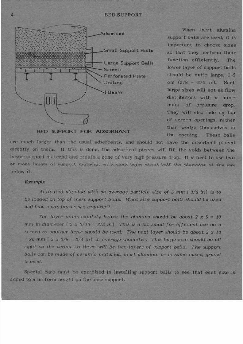
When inert alumina
support balls are used, it is
important to choose sizes
so that they perform their
function efficiently. The
lower layer of support b lls
should be quite large, 1-2
em (3/8 - 3/4 in . uch
large sizes will act as flow
distributors with a mini
mum of pressure drop.
They will also ride 011 top
of screen openings, rather
than wedge themselves in
the opening. These balls
are much larger than the usual adsorbents, and should not have the adsorbent placed
directly on them. If th is is done, the adsorbent pieces will fill the voids between the
larger SUppOl t nHtterial and create a zone of very high pressure drop. t is best to use two
below it.
Example
Activat.ed alumina with an average particle size of 5 mm (3/6 in] is to
be loaded on top of inel t support. balls. What size support balls should be used
and how m ny layers are required?
The Layer immmediately below the alumina Should be about 2 x 5 1
mrn in diameter l x 3;'16 3/8 in I This is a bit small for efficient use on a
screen so another layer should be used. The next layer shouLd be about 2 x 1
= 20 mm I 2 x 3/8:: 3/4 inJ in average diameter. This large size should be all
righi on the screen there will be two layers of support balls. The support
balls can be made of ceramic material inert alumina, or in some cases, gravelused.
SpfX ial care must b( > exercised in installing support balls to see that each size is
added to a uniform tleight on the base support.

8/14/2019 API - Solid Bed Adsorbers.pdf
http://slidepdf.com/reader/full/api-solid-bed-adsorberspdf 12/70
c. Insulation
EXTERNAL INSULATJON
INSULATION 5
During the course of an adsorption cycle,
the adsorbent is regenerated by passing a stream
of hot gas through it to boil au the material th t
was adsorbed. The tower must be insulated to
prevent the hot regeneration gas from rosing some
if its heat and thereby reducing the efficiency of
regeneration.
u o n can be ex ternal or internal de-
pending upon the service of the adsorbe r, and thelength of the adsorption cycle. When insulation is
internal.' or inside the tower, the hot regeneration
gas does not heat the steel in the vessel. [ his
reduces the size of "'the regener tion gas hea ter by
25 -50%.
There are two different types of internal
insulation. One is a light gauge steel shell, or
'can', about 10 cm (4 in) smaller in diameter than
the inside of the main vessel shell. t is welded to
a r ing t the top or the bottom, and th,- s creates a
dead gas space between it and the vessel shell.
The dead gas space acts as an efficient insulator.
The other type is insulation material th t is c st or sprayed on the inside of the vessel in a
layer thick enough to provide the insulation required.
During heating and cooling, as the adsorbent is regenerated, the insulation expands
and contracts. t requires expert design and installation so th t t will not fa il in service.
The internally insulated vessels are more expensive to build, and repair of an
insulation failure can be very expensive.
The adsorber with ;external insulation is ~ s s cost , but requires more regeneration
heat in order to heat the steel of the vessel during the regeneration ph.ese.
Adsorbers in h y d r o c r ~ o n recovery service which have an adsorption cycle of less
than one hour are usually internally insulated.

8/14/2019 API - Solid Bed Adsorbers.pdf
http://slidepdf.com/reader/full/api-solid-bed-adsorberspdf 13/70
6
I I I
CAST TYPEINTERNAL 1 I9lJLATION
V LVES AND PIPING
I I I
C N TYPEINTERNAL I lSULA TION
The choice between external and internal insulation for systems operating on longer
cycles depends on fuel cost operating pressure, and other factors beyond the scope of this
manual
D Valves and Piping
The adsorption process is a batch type operation. The inlet fluid flows through an
adsorber tower until the adsorbent is saturat ed with the contaminant it is removing from
the fluid. At that point, flow is switched to a tower containing freshly regenerated
adsorbent, and the original tower is regenerated.
A switching valve arrangement is required to divert the flow of process fluid from
one tower to the other, and at the same time, start flow of regeneration gas to the tower
which has been in adsorption service. A typical piping manifold for a 2-tower adsorber
plant is shown on the opposite page. In this illustration, the main gas stream is flowing

8/14/2019 API - Solid Bed Adsorbers.pdf
http://slidepdf.com/reader/full/api-solid-bed-adsorberspdf 14/70
VALVES AND PIPING 7
into the top of Tower 1 and leaving at the bottom of the tower. Regeneration gas is
flowing to Tower 2. Flow may be upward or downward depending on the requirements of
the plant. This will be discussed in more detail l ter i 1 the manual.
The positions of the various switching valves are indicated on the drawing. When
the towers are switched, that is, the flow of inlet gas is diverted from Tower 1 to Tower
2 the position of each switching valve changes to the opposite of that shown on the
drawing. In other words, each valve that is l o ~ e d moves to the open position, and vice
versa.
The regeneration gas lines and valves are smaller than the main flow lines because
the flow rate of regeneration gas is considerably less than that of the main pl ocess flow.
TOWeR 2
TOWER 1
y '
= = : ~ ~ ~ r = ? ~ ~
''
PIPE MANIFOLO FOR Z TOWER AOSORBER PL NT
TOWER 1 IS ADSORBING
TOWER 2 IS REGENERATING
8/14/2019 API - Solid Bed Adsorbers.pdf
http://slidepdf.com/reader/full/api-solid-bed-adsorberspdf 15/70
8 VALVES AND PIPING
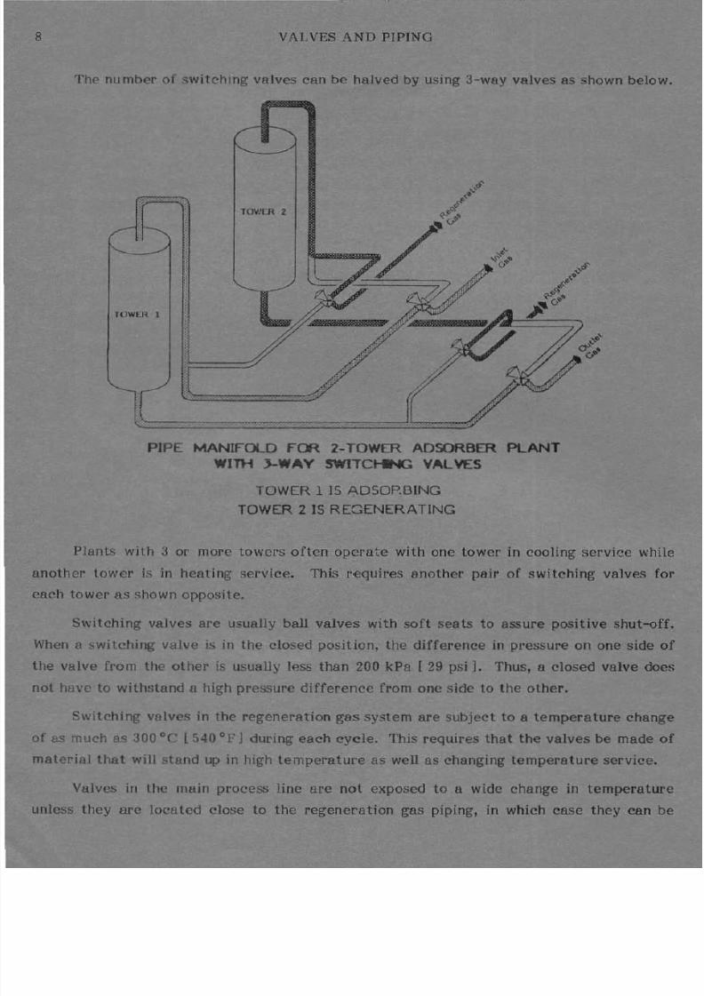
The number of switching valves can be halved by using 3-way valves as shown below.
U W U ~ I
PIPE MANIFOLD FOR 2 TOWER AOSORBER PLANT
WITH J WAY W J T C ~ VALVES
TOWER 1 IS AOSOP.BING
TOWER Z IS REGENERATING
Plants with 3 or more towers often operate with one tower in cooling servi" c while
another tower is in heating service. This requires another pair of switching valves for
each tower as shown opposite.
Switching valves are usually ball valves with soft seats to assure positive shut-off.
hen a switching valve is in the closed position the difference in pressure on one side of
the valve from the other is usually ~ s s than Z kPa [ 9 psi]. Thus, 8 closed valve docs
not have to withstand a high pressure difference from one side to the other.
Switching valves in the regeneration gas system are subject to a temperature change
of as much as 300°C [540 OF] during each cycle. This requires that the valves be made of
material that will stand up in high temperature 8S well as changing temperature service.
Valves in the main process line are not exposed to a wide change in temperature
unless they are located close to the regeneration gas piping, in which case they can be

8/14/2019 API - Solid Bed Adsorbers.pdf
http://slidepdf.com/reader/full/api-solid-bed-adsorberspdf 16/70
V LVES AND PIPING 9
heated by the hot regeneration gas.
A pneumatic or electric activator is mounted on valves in plants that are not
manually switched Pneumatic actua tors are usually 8 piston or diaphragm type A timer
usua lly activates the switch ing sequence that results in valves changing from one position
to another
Each valve operates several times 8 day sometimes over 8 wide temperature range
and the fluid flowing in the valve often contains pArticles of adsorbent. This combination
of frequent operation wide temperature range and erosive fluid is one of the most
demanding serv ices on any equipment in the oilfield.
TOWER 1
PIPE MANIFOLD FOR 3 TOWER ADSORBER PLANT
TOWER 1 IS ADSORBINGTOWER 2 IS HEATING
TOWER 3 IS COOLING

8/14/2019 API - Solid Bed Adsorbers.pdf
http://slidepdf.com/reader/full/api-solid-bed-adsorberspdf 17/70
10 TYPES OF ADSORBENTS
Proper valve selection and maintenance is required to assure trouble-free operation.
There are also sw itching valves in the regenerat ion gas line to by-pass the heate r or
other he t exchangers in the system. Refer to nual 8 2 for descr ip tion of valves and
equipment not covered in this manual.
The va lve switching arrangement may vary considerably on plants with three or
more towers depending upon the type of cycle. A 3-tower plant may have one tower
regenerat ing and the other two towers in parallel adsorbing service or it ma y have one
adsorbing one coo li ng and one hea ting A 4-tower plant may have two lowers adsorbing
and two lowers regenera ting at the same tim e
Problem 1
atch the items in the two columns:
Internal insulation
Bed support
Distribution plate
_ Switching valves
A m m o n ~ o f ~ r o e n b
a Hold adsorbent in tower
b. Prevent adsorbent breakage
c. Operate by air presure or electric motor
d Less regeneration hea l
ll. ADSORPTION
There are four types of adsorbents widely used in the gas processing industry. They
are: act ivated alum ina activated charcoal or ca rbon molecular sieves and silica ge l In
the case of the alumina and cha rcoal the term act ivated refers to some treatment thatimproves the capacity or efficiency of the adsorbent.
All of these ma ter ials have several common characteristics. They are aU strong
dense solid particles. Althou gh they do not look like it they all have a physical structure
that is filled with cav iti es or pores like a sponge. These pores are so small they cannot
be seen even with a s trong microscope. But they are large enough so that gas and the
contaminants it carries can enter. Once inside the particle of adsorbent the con
aminants condense and cling to the surfaces of the inner chambers and the purified gas
passes out.

8/14/2019 API - Solid Bed Adsorbers.pdf
http://slidepdf.com/reader/full/api-solid-bed-adsorberspdf 18/70
TYPES OF ADSORBENTS 11
The amount of sU rface area available in many adsorbents is so great that if you
could unfold it and spread it out there would be enough from a spoonful of adsorbent to
cover a football field. This unseen surface is what makes the adsorbents differ from
beads or rock particles they resemble.t
provides so much surface area for adsorptionthat some of the grades of silica gel, for example, can adsorb as much as 33 liters of
water per cubic meter (two and one half gallons of water per cubic foot) of adsorbent.
When the silica gel holds this much water it does not change if] apeararice. t does not
look wet. of the water is a sorbed in the Rores, where it is condensed and held on the
inner surface.
ACTIVATED ALUMINA MOLECULAR SIEVES SILICA GEL
ADSORBENTS
In addi tion to having tremendous surface area where adsorption can take place, the
adsorbents have attractive forces on their surfaces. hese forces act like magnets, to
condense and hold material on the surfaces even when the system temperature and
pressure are not near the condensation point. At high temperature however, the vapor
pressure of the adsorbed liquid can become so great that it can overcome the adsorptive
forces. When this happens, the liquid that was adsorbed will vaporize and return to thesurrounding gas. In this way the adsorbed material can be recovered, and the adosrbent
can by empti ed and made ready to adsorb again.
Different types of adsorbents have forces that are somewhat selective. This means
that for each type of contaminant to be removed there will be one or two of the adsor-
bents that are more efficient than the others.
1. Activated Carbon
c t i v a t e ~ carbons or cha rcoals are made by the partial burning of materials such as
coal, wood, bones, fruit pits, and nut shells. Their adsorbate preference is, to a large
extent, dependent on the material from which they are made. They have little attraction

8/14/2019 API - Solid Bed Adsorbers.pdf
http://slidepdf.com/reader/full/api-solid-bed-adsorberspdf 19/70
12 TYPES OF ADSORBENTS
for water Most of them have high ca08city for of1Zsnic mAtp riRls such 9 S h y r o ~ r h o nFor this reason they are frequently used to adsorb traces of organic impurities from gas or
liquid st reams. They can also be used to adsorb LPG from natural gas.
Because of its attraction fo r heavy organic materials, such 8S compressor lubricantsand g lycol, activated charcoal is so metimes used 8S 8 buffer , I t is placed ahead of o ther
adsorbents in the adsorption system. There, i t adsorbs the heavy organics and prevents
them from contaminating the in adsorbent
2 Activated Alumina.
Ac tivated aluminas are made of aluminum oxide, A12 0 3 There are several
different kinds available. They vary in their purity and capacity. They also are available
in different forms, fro m rough gra nules to smooth uniform beads. Their surface forces
prefer wa t er. They also attrac t and hold a lcoho ls and glycols and heavy hydrocarbons.
They are usually used as desiccants, t hat is, for water adsorption.
Some of the ac tivated aluminas are among the toughest of the commercial
adsorbents. They are used when the adsorbent may be subjec ted to physical da mage.
Slugs of liquid water or condensate can break silica gel or molecular sieves, but will do
less damage to alumina. Where such abuse is expected, alumina may be used for theentire bed, if dehydration is the only concern, or, it may be used in a buffer layer such as
that described for activated charcoal.
3. Moleeular Sieves
Mo lecular sieves are ch emically sim ilar to aluminas. However, they have a diff
erent cavity structure The aluminas hav e cavities of all sizes and shapes, bu t all the
cavities in the molecular sieves are the same. Difrerent grades of molecular sieves are
available with different sizes of holes between the cavities. These holes are about the
same size as many of the molecules found in gas streams. For example, a normal butane
molecule is about the size of the holes in 8 Type 5A molecular sieve Type 5A will adsorb
normal butane. But a molecule of iso-butane is shaped so that it is larger than the holes,
or pores, in the Type 5A and it cannot be adsorbed. Thi s type of selection, based on
molecule Size, is why these adsorbents are called molecular sieves.
The surface in the molecular sieve structure has a great preference for water. It
will also hold alcoholS very strongly, and some other organic materials. It also has good
affini ty for some acid gases such as H 2 S and CO 2 . Molecular sieve adsorbers ca.n be used

8/14/2019 API - Solid Bed Adsorbers.pdf
http://slidepdf.com/reader/full/api-solid-bed-adsorberspdf 20/70
TYPES OF ADSORBENTS 13
used to remove these acid gases from natural gas and from LPG.
Besides the typ S there is Type 4A which is the grade most frequently used Cor
dehydration. Its attraction for water is so strong that it can remove almost 100 of the
water from gas. Another type that is sometimes used in gas treating is Type 3A. The
pores in this type are so small that water can be adsorbed but most other components of 8
gas stream will not enter the pores. Type 13X is another kind that is usually used to
adsorb H 2 Sand mercapto ns from LPG
4 Silica Gel
There are two kinds of silica gel used to treat gas. One is in the form of eIehf
granules that look lik pieces of broken glass The other is in the shape of small spheresSometimes the spheres have an amber color. Although the two types do not look alike
they usually work about the same way. They both arc like the aluminas and the molecular
sieves in that their surfaces prefer water to all other material. For this reason they are
frequently used in dehydrators. They cannot dry gas Q <; completely as the mOlecular
sieves.
ADSORBER TOWERS I l GAS DEHYDRATION SERVICE

8/14/2019 API - Solid Bed Adsorbers.pdf
http://slidepdf.com/reader/full/api-solid-bed-adsorberspdf 21/70
14 TYPES OF ADSORBENTS
Silica gel has such an affinity for water that if a drop of liquid water touches a
particle of it, it will adsorb the water so quickly that the silica gel will actually
disintegrate Consequently, gas entering a bed of silica gel must not contain any free
water. Quite often, a special water resistant grade of silica gel that is not affected bydroplets of water is installed at the entrance to the bed.
The silica gels also have good capacity for natural gasoline fractions in gas. They
can be used to , ecover C s fractions along with waiet . Sometimes this ability is used to
remove just enough heavy hydrocarbons to meet pipeline gas specifications for both water
and hydrocarbon content.
Silica gel in the granule form is less likely to coke-up when the gas contains heavy
hydrocarbons. This type of desiccant is well suited for drying gas on the outlet of a
compressor, when the gas contains some lubricating oil.
SUMMARY OF SOME COMMON COMMERCI L ADSORBENTS
ADSORBENT
Activated Alumina
Activated Carbon
Silica Gel
Molecular Sieves
Type A
Type 4A
Type 5A
Type 13-X
V IL BLE SHAPES
Irregular granules
and spheresIrregular granules
and pellets
Irregular granules
and spheres
Pellets and Spheres
TYPIC L APPLICATIONS
Drying gases and liquids and
buffer layersRecovery of light hydrocarbons
from gas. H 2 S removal from
gasses. Buffer layers to protect
desiccants
Drying of gases and liquids, re-
covery of C 5 +NGL; Hydrocar
bon dew point controL
Drying of gas and liquids when
exclusive selectivity for water
is required
Drying v8I ious gases and liquids.
Sweetening gases. Separation of
ISO and normal fractions of
straight chain hydro-carbons.
Sweetening LPG with simultan
eous drying.

8/14/2019 API - Solid Bed Adsorbers.pdf
http://slidepdf.com/reader/full/api-solid-bed-adsorberspdf 22/70
GAS DEW POINT 15
Problem 2
Choose the adsorbent from the following list for each of the situations described
below. In some cases there may be more than one adsorbent which will do the job.
1. Activated Charcoal 4 Type 4A Molecular Sieves
2 Activated Alumina 5. Type SA Molecular Sieves
3. Silica gel 6. Type 13X Molecular Sieves
a. An LPG stream is saturated with water and c o n ~ i n s 45 ppm H 2 S. It must be dried
and sweetened. Can this be done with one adsorbent? Yes No
b. f you think the answer to a is yes which adsorbent should be used?
c. Natural gas is to be processed through a lean oil absorption plant. It is saturated
with water at its f l o w i ~ temperature of 300 e [86°F 1 It must be dried to a dew
point below 40°C [ 40°FJ . Which desiccant can be used?
d. A gas transmission line goes though an area where winter temperature may be as
low as -5°C [ 22 OF ]. The gas has a hydrocarbon dew point of 4°C [ 39 OF] and a
water dew point of 10°C [50 OF]. An adsorption plant will treat the gas so there
will be no hydrates or condensate formed at any time. What adsorbent should beused?
e. A dehydrator containing activated alumina is being used to dry a gas stream that
contains quite a bit of propane and butane. There is a smaUlocal demand for LPG.
The plant operator would like to recover some of the propane and butane, but the
market is not large enough to justify building a lean oil plant or a turbo expander
plant. Should he consider changing the adsorbent in his adsorption plant?
Yes Nof. If the adsorber is to be used to recover some LPG which adsorbent should be
used?
B. Gas ew Point
In the oilfield most adsorbents are used to remove moisture from gas. In some
situations, adsorbents remove moisture and hydrocarbons or H 2 S simultaneously. In order
to determine the effectiveness of gas dehydration facilities, the outlet gas must be tested
for water content.

8/14/2019 API - Solid Bed Adsorbers.pdf
http://slidepdf.com/reader/full/api-solid-bed-adsorberspdf 23/70
16 GAS DEW POINT
The most common method for measuring the water content in gas is that of
determining the dew point temperature. The dew point temperature normally referred to
as the ew point, is the temperature at which water will condense from gas. The relative
humidity of gas at its dew point temperature is100 . In
other words, i f gas containingwater vapor is cooled to the point that some of the water turns to 8 liquid, the
temperature at which liquid first starts to form is the dew point.
abe quantity of water vapor contained in gas at its dew point will depen l upon the
gas pressure. Figures lA and IB indicate the amount of moisture that gas can contain at
various temperatures and pressures. When gas is at is its dew p o n t ~ its water content will
be that shown on the curves.
Most gas delivered to pipelines for commercial use has maximum water content
spec ification of 112 kg per million m 3 [ lbs per MMcfl. The dew point temperature of
pipeline specification gas will depend upon the pressure at which gas is delivered.
Example
Determine the dew point temperature for gas entering Q pipeline at
55 kpo [ OO psi].
From Figures 1A and 1B move up the left hand column lUltil you reach
the water content 112 kg [7 Zoo ] ; follow this line to the right until t
intersects the pipeline pressure 5500 kPa [ 800 psi 1. Move downward from
this point and read the gas temperature of -2°e [28°Fl.
The dew point of pipeline spec if ication gas at 5500 kPa [800 psi] is
2 [2B F].
Problem 3
What is the dew point of pipeline specification gas at 4000 kPa 580 psi? ]
The water content graphs are also used for determining the amount of water which
must be removed from gas in a dehydration plant.
Example
Gas flowing at a rate of 3 million std. m31d [ 106 MMscfl dl enters a
dehydration plant at 35°e and 7500 kPa {95°F and 1090 psi}. Dry gas from
the plant enters a cryogenic plant where its temperature will be lowered to

8/14/2019 API - Solid Bed Adsorbers.pdf
http://slidepdf.com/reader/full/api-solid-bed-adsorberspdf 24/70

8/14/2019 API - Solid Bed Adsorbers.pdf
http://slidepdf.com/reader/full/api-solid-bed-adsorberspdf 25/70

8/14/2019 API - Solid Bed Adsorbers.pdf
http://slidepdf.com/reader/full/api-solid-bed-adsorberspdf 26/70
PRINCIPLES OF ADSORPTION 19
-73°C [ 100° Fl . The water content of the ry gas must be almost zero Determine how
much water must be removed from the gas each day.
Gas temperature
Cas Pressure
1
2.
Max water content inlet gasFigures lA and BJ
Water content outlet gas
Water removed in dehydration
plant
Gas flow rate
Total water removed day
SIUNITS
38°C
7500 kPa
9 kg million std. m 3
okg/million std. m 3
900kg/million m l
3 million std. m 3/d
9 x 3 =2700 kg d
NG LISH UNITS
100°F
1090 psi
57Ibs MMsc{
o bs/MMsc{
57Ibs MMc{
1 6 MMsc{ d
57 x 1 6 = 6042 lbs d
The dew point normally refers to the temperature at which water first starts to
condense from gas when it is cooled. However, i t may also re fer to the temperature at
which hydrocarbons start to condense from gas. In this case t is qualified by using the
word hy<kocarbon before the dew point
In Canada Bnd other cold weather countries adsorption plants are often installed to
simultaneously remove moisture and condensable hydrocarbons from gas prior to its entry
into a pipeline. Such facilities are designed to produce outlet gas having a maximum
specified water dew point a nd hydrocarbon dew point. The amount of water vapor
removed from the gas is ca lculated from Figures lA and 28. h ~ qu antity of hydrocarbon
which must be removed requires a sophisticat ed procedure of calculation which is beyond
the scope of thi s manual. Needless to say, the quantity of adsorbent used in the plant will
be the sum of that required to remove moisture plus that required to remove
hydrocarbons.
C. Principles of Adsorption
1. Equilibrium Loading
Almost a ll solid materials can act as adsorbents und er proper conditions. A good
example is a mirror or a window, which is fogged with water. In this case, the glass
surface acts as an adsorbent. Conditions are such that water, wtiich is in the air as a
vapor, condenses on the glass surface.
In a gas system , the amount of material that condenses on the adsorbent, and the
amount that remains in the gas, respond to a relationship referred to as equilibrium. Thi s

8/14/2019 API - Solid Bed Adsorbers.pdf
http://slidepdf.com/reader/full/api-solid-bed-adsorberspdf 27/70
20
30
2
15
, ,
TT ,
- ,
. ..:.. ..:
, ,
EQUILIBRIUM LOADING
' SI UNITSI
: :I
, I, ,
,c;
I
to' ·
I '
• - · 1 -I, T
.. .; h-t
I . I
C {'
30
i '
25
fI
20I
t ,,
15
-10
- r I : 0 ?-<{; f : :t -
~ : _ ~ 4 i ~ i l i ~ ~ ~ ~ ~ ~ ~ ~ < { ; ~ ~ i ~ ~ ~ ~ : i · ' i : i ~ ~ i ' : ~ ~ i i i ~ q ~ ~ 0 ~ ' O f ; ~ C f j 6 0 :3 - 20 10 0 10 2 3 4 5
GAS DEW POINT oC
Figure 2
GAS DEW POINT OF
Figure 2B
WATER LOADIIIG aJRVES FOR ACTIVATED ALLNNA
30
20

8/14/2019 API - Solid Bed Adsorbers.pdf
http://slidepdf.com/reader/full/api-solid-bed-adsorberspdf 28/70
EQUILIBRIUM LOADIN G 21
relationship is different for each adsorbent-adsorbate combination. At equilibrium an
adsorbent can hold a certain amount of the adsorbate when it is in contact with 8 gas
containing 8 speci fic amount of the adsorbate.
f the amount of adsorbate in the gas changes then a new equilibrium will control
the relationship The adsorbent will hold 8 different amount Usually the amount of
adsorbate that can be held by a solid material will be greater i f there is more in the gas.
Temperatu re wiU also influence the equilibrium relationship. At higher temper-
atures the adsorbent will hold less than at low temperature.
The equilibrium relationship can be shown by adsorbent loading curves such 8S those
on the oppOSite page Each curve in these Figures shows the amount of water that
activated alumina will hold at a given temperature and gas dew point.
Example
a. How much water can alumina hold if it is in equilibrium with a gas at
25°C [77°FI and the gas has a dew point of oO [32°FI.
Since the gas temperature is 25°C [ 77 °F 1 the curve for this tempera-
ture will define the situation. Find the intersection of the 25°C [ 77 °F ]
curve and the O°C [32°F J dew point line. Then I ead straight across to
the left scale. The desiccant water holding capacity is 10. OX. f 3000 kg
[6600 lb] of desiccant is contained in a tower it will theoretically
remove 10.0X of its weight or ·300 kg { 1660 lOO) of water from gas.
b. What will happen if the gas temperature is raised to 50°C [122°FI
after the alumina adsorbed 10.0 water?
Reading to the left from the intersection of the 50°C [ 122 FI curve and
the DoC [32°F] dew point line we see the desiccant capacity is only 5.0 .
Therefore water will leave the desiccant Wltil it holds only 5.0 . The
water will return to the gas, as a vapor. This is a way that an adsorbent
can be stripped of its load and prepared for another period of adsorption.
When this is done we say the adsorbent has been regenerated , or
reactivated .
These water loading curves and similar curves which are published for other types
of adsorbents are based on laboratory conditions. Such conditions are never possible in an
operating plant. For this reason the operating loading for an adsorbent is always much

8/14/2019 API - Solid Bed Adsorbers.pdf
http://slidepdf.com/reader/full/api-solid-bed-adsorberspdf 29/70
22 EQUILIBRIUM LOADIN G
less than the published equilibrium values. We say that the adsorbent in a plant reaches a
dynamic equilibrium l d i ~ This is usually called the 'useful capacity' of the adsorbent
under the operating conditions of the plant. As 8 'rule of thumb', the useful capcity of an
adsorbent is usually about 40-45 01 the laboratory equilibr ium capaci ty shown in the
curves o page 20.
Each adsorption process plant acts like an equilibrium 'system', In 8 dehydrator, for
example, the adsorbe nt takes water from the gas in an attempt to load to the equilibrium
leve l During regeneration the adsorbent has more water than it can ho ld in equilibrium
with the hot gas, so it gives up water.
Some adsorption systems are designed to remove contaminants other than water.
For example, H 2 S can be removed by adsorption. In this case, the adsorbent would be
molecular seives. The opera tion would be based on the molecular sieve - H 2 S equilibrium
relationship.
In some plants the adsorbent is chosen to remove rPore than one contam inant. In
that kind of plant the adsorbent will have an equilibrium relationship with each of the
differe nt adsorbates.
2 Selectivity
Most adsorbents hold some types of material more strongly than others. This char-
acteristic is called selectivity. Since there are many different materials in a natural gas
strea m, it is important to use an adsorbent that is selective for the main contaminant to
be removed. f two materials are to be removed in the same system the adsorbent must
be chosen to ha ve selectivity such that those two are the ones most strongly held.
t is not always possible to find an adsorbent that sha.ws proper selectivity for every
combination of contaminants. Sometimes it is necessary to u ~ two different adsorbents
in the same system to remove two different adsorbates. Likewise, some materials iI the
gas st ream may be attracted to an adsorbent, even if it was not chosen to remove them.
3. Competition
When a gas stream contains more than one materia l that can be adsorbed, the
adsorbent's capacity for each will be less than if there were on Iv the one adsorbate. This
is because the different adsorbates will compete for the surface where they can be
adsorbed. Such competition can change the performance of an adsorption system.

8/14/2019 API - Solid Bed Adsorbers.pdf
http://slidepdf.com/reader/full/api-solid-bed-adsorberspdf 30/70
ADSORPTION FROM A MOVING STREAM
rample
A silica gel dehydrator in western Canada may have a capacity to dry
7 m3/d [ 2 MMscf/d] in July. In January the capacity may be reduced to
less than 50000 m 3/d [1 4 MMscfd]. This is because methanol is injected in
the gathering system in cold weather for hydrate control. Silica gel has
selectivity for water but it also adsorbs methanol. The methanol will
compete with the water for adsorption space. Although the water will be
preferentially adsorbed, there will also be some methanol adsorbed, The space
taken by the methanol will reduce the water capacity of the dehydrator.
m THE ADSORPTION PROCESS
A Adsorption From a Moving Stream
23
hen adsorption processes are used to treat natural gas the adsorbent is contained
in vessels called adsorber:; or adsorber towers. The adsorbent in the towers is referred to
as beds of adsorbent.
Gas is piped to the towers so that it flows through the bed of adsorbent. Sometimes
the flow is from bottom to top, but more frequently it is from top to bottom. During the
time the gas is in contact with the adsorbent, the adsorbates transfer from the gas to the
inner surface of the adsorbent, where they are held.
As gas flows through an adsorption plant, the transfer of adsorbate from gas to the
adsorbent surface is governed by the equilibrium relationship for the particular adsorbent-
adsorbate system, at the temperature and adsorbate content of the inlet gas. When the
adsorbent has loaded to equilibrium with the incoming gas, the bed is not able to removeany more of the contaminant from the gas. The gas is then switched to another tower
containing fresh or regenerated adsorbent. All plants have two or more beds that can be
switched back and forth in this manner.
When gas flows through a bed of adsorbent it does not remain in contact long enough
to establish a true equilibrium condition. Rather, a dynamic equilibrium condition
develops. The diagrams on Page 25 illustrate the progress of a desiccant bed loading to
dynamic equilibrium in a gas dehydration plant.
The strength o( attraction between the desiccant and the water in the gas is called
the driv ing force . The driving force determines how (ast the water will be adsorbed.
When this force is large the rate of water transfer from gas to the desiccant is very fast.

8/14/2019 API - Solid Bed Adsorbers.pdf
http://slidepdf.com/reader/full/api-solid-bed-adsorberspdf 31/70
4 ADSORPTION FROM A MOVING STREAM
The driving force is proportional to the difference between the water load actually on the
desicc nt and the w ter load the desicc nt could hold if it re ched equilibrium with the
gas
When the dsorpt ion first st r ts in the sys tem on Page 25 the gas is s tur ted with
water, and the desiccant has a lmost no water. This is 8 s trong driving force, so the water
in the first bit of gas will rapidly transfer to the top layer of desiccant. The adsorption
will be rapid, but it will not be instantaneous. The gas will still have some of its water
when it reaches the next layer of desiccant.
Since some of the water has been adsorbed, the water content of the gas at this
. point is less than when t entered the bed. The driving force for adsorption is less than at
the start beca use there is less water in the gas. Since the dri ving force for adsorpt ion of
the remaining water is less than was the driving force in the beginning, the next bit of
adsorption will be slow er. As the gas continues its downward flow, its water content is
continually redu ced and the dr iving force fo r adsorp tion of the small amount of rema ining
wa ter is a lso lower. At some point, the water cont ent in the gas is so low that there is no
driving force to move it to the desiccant.
The gas passes on through the rest of the bed, with no chang e in its water content,
and no change in the water content of the desiccant. As gas flow continues, the water in
the desiccant continues to increase so the driving force becomes less at each point along
the bed. Finally the first laye r of desiccant becomes loaded to dynamic equilibrium with
the incoming gas. This means there is no longer a dr iving force for water to be adsorbed
in that layer, so the gas has to pass further into the bed before it gives up so much water
that it is in equilibrium with the active desiccant. The distance the gas travels between
the layer of desiccant that is loaded to dynamic equilibrium with the feed, and the layer
of desiccant that adsorbs no water because the gas contains so little there is no driving
force, is called the mass transfer zone MTZ). Another way of thinking of the mass
tr nsfer is the dist nce through the bed th t the gas goes as its dew point changes from
that at the inlet of the dehydrator to that as it leaves the dehydrator. As more wet gas
enters the adsorber more of the inlet part of the desiccant becomes loaded to dynam ic
equilibrium. This means that the gas has to travel further into the bed to give up its
water. The mass t ransfer zone moves deeper into the bed, S shown in the illustration,
opposite.
The speed with which the tr nsfer zone moves through the bed depends on the

8/14/2019 API - Solid Bed Adsorbers.pdf
http://slidepdf.com/reader/full/api-solid-bed-adsorberspdf 32/70
Ma.
Tl1In. .rZane
Active
Ory Outlet GI.
Entira bad II active at
ttQrt of adtorptlon. herna. tranefer zone la at
the top of the bed.
MASS TRANSFER ZONE
Satul1ltBdWith
Water
MI.TransferZone
Active
Midway In adaorption,upper part part of bed I.
.aturated and lower pertla active. Ma. transfer
zone separatel the twolayers.
5
SatUl1ltBWithWater
TranlferZone
At the end of adaorption, the bottom of therna. tranafer zone la at
the bottom of the bed.
MOVEMENT (J MASS TRNoI9' ER ZONE Tl ROlQi ADSORBENT BED
amount of water in the gas, and the gas flow rate. In a properly designed system the mass
transfer zone will reach almost to the bottom of the bed at the end of the adsorption
cycle.
Different types of adsorbers are designed with different rates of mass transfertravel. LPG sweeteners, for example, are designed for very slow movement, maybe
something in the order of one or two meters per day [3-6 ftlday I.
Gas dehydrators, on the other hand, frequently have mass transfer zones that move
as fast as ten or twelve meters per day [33-40 ft/day I, and some hydrocarbon dew point

8/14/2019 API - Solid Bed Adsorbers.pdf
http://slidepdf.com/reader/full/api-solid-bed-adsorberspdf 33/70
26 BREAK POINT
control plants have hydrocarbon mass transfer zones that move 8S fast 8S six 01 seven
meters per hour [20-23 ft hr J.
When the MTZ gets so near the exit tha t there is no longer a layer of active
desiccant to come into equilibrium with the gas leaving the system, the next bit of gas
will leave the bed still containing a small amount of water. This point in the adsorption
cycle is called the break point. Gas must be switched into 8 fresh tower at this point.
Otherwise, the water content of gas leaving the tower will rise, as shown on page 27.
In some dehydration plants, the outlet gas from an adsorber is continuously tested
for water content. During the period when there is active desiccant below the mass
transfer zone, the water content will be constant. It will be at the level determined bythe equilibrium relationship between the regenerated desiccant and the gas. At the break
point, the water content of the outlet gas starts to rise. A plot of outlet gas dew point vs.
time is shown in below. Of course, properly ~ s i g n e and operated plants switch beds
before the break point occurs.
40°F [104°fJ
....
j?;
~~ wc [68 Flo
~(J
~ O C[J2 FJ
B_20 C [ -4° Fl
-2S C [-lS F]
-
+-,
, '-
I1--;--- --- -
r-
f Fr---r -
, . .--
I I
t
I I-40 C [-40 FJ 0
1 2
: t lt, J , J - k J , t t - k l k ~ -
I ~ f L l t A ~ D E W ~ O X--
r-t-- t + LI ,
iI I
I, I
<- I....... _ ...... _. - +
-+- - . -- 1 + l . . ..,. + 1-- - -- + - + -i-... . . .- . . . .
---
I+-
-:- - f-- + l- I - c--1-. tI
I i -- c- . t ;- -. . ~
t R 1 A K t O I ~ i i I -- tt+ I
I I
+ rI t L +, I ,
-
i- I--- -
~ t--- .
-I r- t- .I
J 4 S 6 7 II ,
TIME, HOl.ftS
10 11 12
AOS£RPTDN
ryPlCAI.. BREAK ll-ROUGH CUl.VE FCR GAS DEHYDRATION
l::::
I-l
-
---.--
l
lD

8/14/2019 API - Solid Bed Adsorbers.pdf
http://slidepdf.com/reader/full/api-solid-bed-adsorberspdf 34/70
MA TR NSFER ZONE 27
Wet Inlet Gas Wet Inlet Gas
30 C
[86 F]
30 C
[ 86 F]
Ms
TrenderZone
DP 30 C [86 F]
DP 20 C [68 F]DP 10 C [50 F]
I ~ ~ § § i § § i § DP O C [32 F]
DP 30 C [86 F]
DP 20 C (68 F]
DP 10 C [ 50 ] I i
Outlet Gas
DP O C[ 32 C]
Gas dew point at various
posit ions in mS 16 transferzone. Dew point of outletga8 is the same 8S that the
bottom of the zone
Outlet Gas
DP 10 C[ 50 C]
When the bottom of the
mall transfer zone is
below the desiccant
the outlet gas dew
point will rile.
Mao.
ranafer
Zone
GAS DEW POINTS 1 1 MASS TRANSFER ZONE 1 1 GAS DEHYDRATION TOWER

8/14/2019 API - Solid Bed Adsorbers.pdf
http://slidepdf.com/reader/full/api-solid-bed-adsorberspdf 35/70
28 REGENERATION
The capacity of an adsorption plant is based on the amount of material i t can adsorb
before reaching the break point. This is expressed as a percent of the total desiccant
weight.
Problem 4
Desiccant 'A' and desiccant f I both have the same equilibrium capacity for water
under the operating conditions in a large dehydrator. However, desiccant 'BI is known to
have a ms S transfer zone that is almost twice as long as desiccant 'A', Which desiccant
will hold the most water before the break-point is reached?
B. Regeneration
After 8 bed of adsorbent is saturated with adsorbate, the inlet process fluid is
switched to a fresh bed of adsorbent, and the saturated bed is regenerated. Most process
adsorbers are regenerated y passing hot gas through the bed. The hot gas heats the
adsorbent and the adsorbate, and creates an equilibrium situation such that the adsorbent
gives up most of the adsorbate. In other words, lfie adsorbate is boiled out of the
adsorbent, and is carried out of the system in the hot gas stream flowing through the bed.
TemRerature is the primary factor that affects the amount of adsorbate that is
removed from the adsorbent, and the rate at which it is removed. The Higher the temper
ature, Hie f a s t ~ r and more completely ttie aosorbate is removed.
Of course there are some practical limits on the temperature that can be used.
These vary with the different kinds of adsorbents. The carbons can usually be reactivated
with gas temperatures below 315°C [600 of] This is usually about the upper limit of
regeneration systems. Even at such a high temperature, some of the high boiling fractions
and traces of compressor lubricant may not be completely removed. Sometimes activated
ca 'bon syste ms are designed so the beds can be stream stripped to assist in removal of
some of these heavy compounds.
Molecular sieves in dehydration service can be regenerated with gas temperatures as
low as 250° C [482°P] and some plants operate in this range. When molecular sieves are
used to adsorb sulfur c o m ~ o u n d s they are usually regenerated at a gas temperature of
315·C [600 OF l.
Silica gels and activated aluminas give up their water at lower temperatures, so

8/14/2019 API - Solid Bed Adsorbers.pdf
http://slidepdf.com/reader/full/api-solid-bed-adsorberspdf 36/70
REGENERATION 29
they can be regenerated with gas temperatures as low as 200°C [ 392 of 1. However the
use of higher temperatures speeds the removal of waler, so sometimes temperatures as
high as 315°C [600 of 1are used
In hydrocarbon adsorption plants, the cycles are very short, so it is essential thatheat be supplied very rapidly. In these systems, the regeneration gas is sometimes 85 hot
8S [652°F1. Even when long heating periods are used the regeneration gas
temperature needs to be l i S i o ~ r 45-70 OF] higher than the required adsorbent tempera
ture. This is because the effectiveness of regeneration will depend upon how hot the
adsorbent gets, and not how hot the regeneration gas is.
Regenerating with gas at a high temperature does not in itself ensure heating the
adsorbent enough to cook out the adsorbed material. With gas at a temperature of
315°C [600°FJ the highest temperature that the adsorbent will reach is about 290°C
[555F 1. To put i t another way, the highest temperature the adsorbent will reach is about
25°C r45 OF 1 below the temperature of the regenerlltion gas. The size and design of the
heater provided to heat the regeneration gas stream usually limits the temperature to
which the bed can be heated during regeneration.
The flow rate of hot gas must be sufficient to carry out the adsorbate that is boiled
off the adsorbent, 8S well as supply the heat to raise the temperature.
t pre, ,ures below about 4000 kPa [580 psia 1 the quantity of gas required to heat
the system is usually more than ample to carry away water from the adsorbant. However,
at higher pressures the water capacity of the gas is reduced and it is sometimes necessary
to use more regeneration gas than is really required just for heating, in order to have the
necessary water carrying capacity. This problem does not usually occur with systems
designed to remove adsorbates other than water.
Failure to remove aU of the adsorbate results in an overall loss of capacity by the
system. If only 90 of the adsorbate is removed during regeneration, the capacity of the
adsorbent will be only 90 of its potential. Consequently, it is desirable to make sure the
bed is heated enough during regeneration to remove the maximum quantity of adsorbate
from the bed. Even so, it is not at all uncommon for systems to leave up to 1 loading on
the bed after regeneration.
After the bed is heated and the adsorbate is removed, the bed must be cooled in
order for it to recover its adsorptive capacity. A hot adsorbent will have little cat>acity,

8/14/2019 API - Solid Bed Adsorbers.pdf
http://slidepdf.com/reader/full/api-solid-bed-adsorberspdf 37/70
30 REGENER TION
because of the equilibrium relationship which was discussed earlier.
Cooling is usually accomplished by diverting the regeneration gas flow so that it
does not flow through the heater but instead flows direct ly to the hot tower. Flow is
maintained until the bed is cooled to a temperature about 25°C [ 45 of J above the
temperature of the main process stream.
The Dow of regeneration gas in an adsorber may be in the same direction as the
main process stream or it may be in the opposite direction, depending upon the efficiency
of regeneration that is required.
f high efficiency required, that is, essentially all of the adsorbed material must be
removed from the adsorbent, regeneration gas flow is in the opposit direC" tion (countercurrent) to the main process flow. This flow arrangement is used in plants removing
sulphur compounds from gas and those which must remove virtually all water from gas so
that it can enter a low temperature processing plant.
Plants in hydrocarbon dew point service, and those removing moisture from gas so
that it meets typical pipeline specification do not require a high regeneration efficiency.
These plants normally have flow of regeneration gas and the main process gas in the same
direction, (co-current).
One difference between eo-current and counter-current flow of regeneration gas
can be the time required to regenerate. Obtaining the full benefit of counter--current
flow requires a longer period of time and/or more heater fuel to regenerate than co
current flow. The reason for this can be seen if we remember that regeneration is divided
into two parts:
1 A heating period during which hot gas flows through the adsorbent to heat
it and remove the adsorbed material.
2. A cooling period during which the hot adsorbant is cooled to approxi
mately the temperature of the main process stream.
The opposite drawing shows a typical gas dehydration plant in which the regenera
tion and process gas both flow in the same direction. This flow pattern is especially
attractive in short cycle plants, where time avaiable for regeneration is very limited. The
hot gas flows until the upper 70-80 of the bed has been heated. Then the heater is by
passed and cool gas flows to the bed. As the gas removes heat from the upper part of the
bed, it becomes hot, so it heats the last part of the lower section. In this way the upper
part of the bed is eopling while the bottom part is heating, thus saving time and heat

8/14/2019 API - Solid Bed Adsorbers.pdf
http://slidepdf.com/reader/full/api-solid-bed-adsorberspdf 38/70
REGENER TION 31
energy. The cooling gas can also be interrupted before the entire bed is cool. The upper
inlet) section will be cool enough to start adsorbing long before the bottom section is, so
the tower can be switched to adsorbing and the main process gas introduced he main
stream will be dried in the upper partof
the bed and then cool the lower part as it flowsthrough. By the time the lower section is required for adsorption, it will be cool, and at
maximum capacity. This type regeneration procedure is ideal for short cycles. It has
some features which make it less ideal for drying gas that is to be treated in a cryogenic
plant, or when sulfur compounds are adsorbed.
he outlet end of the bed never contacts regeneration gas at its maximum
temperature, so it is not as completely stripped of adsorbed material as the inlet end.
-Coo1nIo
To Uquld
' - '
il Uquld
01. .
llwr
lOW R :
D r ~ i n g )
o m £TCASflJ.TER
Coo
-..

8/14/2019 API - Solid Bed Adsorbers.pdf
http://slidepdf.com/reader/full/api-solid-bed-adsorberspdf 39/70
32 REGENERATION
Since the outlet end activation is what determines how dry the product can be, this co-
current activation does not permit 8 plant to produce as dry a gas 8S the adsorbent may be
capable of producing under other conditions
Wheal the main process stream is used to provide the final cooling of the lower part
of the bed there is a period when the product gas is heated 8S much 8S 5°C [ 5 OF] 8S it
leaves the adsorber. If the gas is going to 8 cryogenic plant, or to 8 low temperature
system of any kind, this heat bump in the flow can cause serious problems.
Another consideration in selecting co-current or cQunter-current flow of process and
regeneration gas is the effect of leaking valves on the quality of product gas. Refer to
the previous drawing: the regeneration gas pressure is about 100-140 kPa [ 15-20 psi]
more than the process gas pressure. if the regeneration switching valve on the outlet end
(bottom) of Tower No.2 does not seat somE: wet regeneration gas will leak into the outlet
product gas. If the product gas must meet pipeline specification for water content, the
leaking gas will probably not result in off-spec gas. However, if the product gas water
content has to be less than 10 ppm, no leaking regeneration gas is tolerable.
For these various reasons, the co-current regeneration arrangement is usually not
used in dehydrators ahead of cryogenic plants, or in systems that are designed to adsorbsulfur compounds. These plants use a counter-current regeneration flow 8S shown in the
figure, opposite. In addition to using a different flcw pattern such plants also use a dry
gas for regeneration, rather than part of the feed strcam. This helps to remove the last
traces of the adsorbed material from the adsorbent so that capacity and efficiency are
maintained close to 100 .
When counter-current flow is used, it is not possible to let the gas being treated
provide 8 part of the cooling. It would be at the feed end where cooling would be
required, and in a hot adsorbent section there would be little or no adsorption. In other
words, the cooling period has to be long enough to cool the entire bed, and not 70-80 as is
possible with c o c u r r e n ~ flow.
With adequate gas flow, and temperature, it is fairly easy to remove most of the
adsorbed material from the adsorbents used in various types oi plants. However, the last
little bit of adsorbed material, even wat2r, is held so strongly that it is much more
difficult to rpmove than the bulk of the adsorbate. Three conditions help in removal of
this last trace . They are: temperature, time, and a pure regeneration stream that
contains virtually none of the material that is being stripped from the adsorbent.

8/14/2019 API - Solid Bed Adsorbers.pdf
http://slidepdf.com/reader/full/api-solid-bed-adsorberspdf 40/70
REGENERATION 33
In 8 commercial gas or liquid adsorber, the temperature is usually limited to 8
maximum of 343°C [650 of J by the fabrication code under which the tower was built. So
even if the adsorbent could stand the higher temperature the vessel could not.
Heating time is another variable that cannot easily be extended in a commercialplant. When the most complete removal of adsorbed material is desired, it is common
practice to choose 8 regeneration stream that is free of that particular material. In a
dehydrator on the feed to 8 cryogenic plant, for example, dry process gas from the plant,
such as the demethanizer overhead, may be used for regeneration gas. This gas ha s been
through the process, and contains almost 0 water. It can help strip the adsorbed water
more completely and thus enable the dehydrator to establish an equilibrium situation
which will provide the most complete water removal from the gas being treated.
TOWERl
(Ofylng)
WTL£T GAS
'-TER
J-lOWER AOlDUIER PLANT W1lH COUNTER-cuv\ENT FLOW
CF PROCESS NoD REGENERATION GAS

8/14/2019 API - Solid Bed Adsorbers.pdf
http://slidepdf.com/reader/full/api-solid-bed-adsorberspdf 41/70
4 REGENERATION
In a sweetener (sulfur removed), it is desirable to remove as much of the adsorbed
sulfur as possible during the regeneration of the adsorbent. These plants are usually
designed with 8 soak period in the heating portion of the cycle. This simply means that
the bed is held t maximum temperature for a h lf hour, to an hour. The soak period
permits time for the last traces of adsorbed sulfur to be stripped from the adsorbent.
This, in turn, allows the adsorber to do a more complete job of removing sulfur during the
next cycle.
In most plants the time allowed for adsorption heating and cooling is controlled
with 8 simple timer. The ratio of time allowed for each function is about 8-5-3. That is,
if the adsorption period is eight hours, the heating period will be five hours and the
cooling period will be three hours. In a liquid treater, such as an LPG sweetener it is
necessary provide time to drain and refill the liquid before and after regeneration. In
those plants, the total time available for heating and cooling is always less than the time
of adsorption.
The reason tha t the cooling period is usually
sho rter than the heating period is th t 20-40 of the
heat input is used to boil off the adsorbed material.The balance of the heat input transfers to the adsor-
bant . Only the heat to the adsorbent must be removed
during cooling.
REGENERATIONGAS SEPARATOR
TWO. TOWER AD5C.f{PTION Pl..ANT

8/14/2019 API - Solid Bed Adsorbers.pdf
http://slidepdf.com/reader/full/api-solid-bed-adsorberspdf 42/70
PROBLEM
Problem 5 HI.ter
Br..p··V lve.
35
~ " " " " " " = - - - - - - - " " " I " " I I " ' " ~ = - + - - - - - - - - - - ",-_ .---------
Ptcce.
CInlet
>u:T CASc;(PARATCR
ToUqwd
[ ) ; ~ l
R e ~ n t o nc•• nowControlll t
Reg"" c.. OutletTill'''''' ReeDrder
1 -::::-:: ::: ) I . __
REGENERATIONCAS t £ATER
OJn.cT GASnLTER
Pt ICe
COutlet
Match the t€mperatures with the locations in the diagram above. The time in the
cycle is just at the end of the heating period for Tower 1
Location Tem ?:erature
A E 30°C BEOp)
B P. 290°C [555°P
C. G 316°C [600 0 p
D 40°C [IOgoP

8/14/2019 API - Solid Bed Adsorbers.pdf
http://slidepdf.com/reader/full/api-solid-bed-adsorberspdf 43/70

8/14/2019 API - Solid Bed Adsorbers.pdf
http://slidepdf.com/reader/full/api-solid-bed-adsorberspdf 44/70
MISCELLANEOUS
I ~ r - Capacity iI - H , + - t - ~ ~
.-'>.b:: c Test + - , ,
: t :±:, ~ ~ - ~ Points r+ Desiccant Capacity Curve ~ -+- t- -
, I TT r-' , . r+ -T T
+ h - - + C h a n ~ e ~ ~ ~ ~ n t ~-i I t r-:-
~H '-rr ,--
l -I , ,
,r J. I,
"+ r 1+ - - , ,
+,
I , - t · ~ - ,r 1 r f- , F l =
~ , -- . H- -L H I
H -1--1 - I -, - .r -L -.-r2- r r - - - r' , h + T f I I
0 500 1000 1500 2000 2500
CYCLE
DESICCANT CAPACITY DECUNE CURVE
xample
You are operating the plant having the decline curve shown above. At
the Crne o cycle 2000 you extend the curve as shown on the dashed line .
You know that the desiccant must have a capacity of at least 7.5% in order to
treat the feed to the plant for the required time You should plan on changing
the desiccant before this point n the capacity is reached. The plant s a two
tower system and each tower adsorbs for 4 hours and is then regenerated in 4
hours.
How long do you have to get the necessary desiccant and plan the
change out? Each tower adsorbs for 4 hours and regenerates for 4 hours so it
takes 8 hours for a complete cycle. Each tower goes through 3 cycles in a day.
The aging curve shows that the 7.5 capacity level should be reached at cycle
2500. You are now at cycle 2000. There are 2500 2000 ~ 5 cycles left 5
cycles.;. 3 = 167 days. Desciccant should be replaced before 167 days.
IV. APPLICATION
37
, I 'I
tF+
I
300
Some adsorption systems are designed to remove only one compound from the
stream :>eing process8d. Others are designed to do do uble duty. In genera l, the different
applicatio:ls can be called dehydration, separation , or purification. In dehydration, only
water is removed. In separation one or more materials will be separated and recovered.
In purification one or more compounds will be removed from a st ream but they will bediscarded, and the main stream will be more valuable, or easier to process, by their
absence.
o

8/14/2019 API - Solid Bed Adsorbers.pdf
http://slidepdf.com/reader/full/api-solid-bed-adsorberspdf 45/70
38 DEHYDRATION
A. ehydration
For dehydration the aluminas silica gels or molecular sieves can be used . The
choice of desiccant will depend on the operat ing temperature, the outlet dew point
required and the composit ion of the st ream. The following figure show s the general
limits for various desiccants Activated carbon is not shown because t has very li t tl e
water capacity so is not used 8S a des iccant.
-100 C[-ISO F]
OUTLET GASDEW POINT
-80· C1-1I0·F]
_65 C
1-85· F]
MOLECULAR SIEVES
ACTIVATED ALUMINAS
SILICA GELS
IN LET GASTEMPERATURE
I65°C
IISO·F]
52 · C1 112S·F]
SO·C
1120·F]
OPERATING R t«E c:F ADSORIIENT USED TO DRY GAl
The figure shows molecular sieves will dry the wa rm est gas a nd also remove water
more completely than alumina or silica gel. The sieves are also the most expensive so
they are usually used only when other adsorbents cannot do the required job.
The temperature of the process stream and the outlet dew point required are only
two factors in the choice of adsorbents. Many other considerations which are beyond the
scope of this manual need to be st udied before a proper choice can be made. Such
deliberations are the respon siblity of those who design adsorption plan ts. There are
however times when conditions change. If this happens it may be necessary to change
adsorbents on the basis of the new operat ing conditions.

8/14/2019 API - Solid Bed Adsorbers.pdf
http://slidepdf.com/reader/full/api-solid-bed-adsorberspdf 46/70
SEPARATION AND PURIFICATION 39
Problem 6
A gas dehydrator was des igned to provide dry gas to 8 refrigerated absorption plant.
The dew poi nt required was -40°C [ -40 of 1 and the operati ng te mperature was 35°C
95 o f . The desiccant chosen for the plan t wa s silica gel. After a few years of
operation it was decided to rep lace the oil absorpt ion plant with 8 turbo-expander that
will chill the gas to -90 o e [ -130°F] and recover e tha ne 8S well as LPG. Should the
desiccant in the dehydrator be changed?
used
B. Separation
f so, what desiccant should be
Th e ma in adsorption separation process in the natural gas field is recovery of LPG
or natural gasoline from gas. This operat ion is usually combined with dehydration. Even
if the gas has been partia lly dried in a glycol contractor prior to coming to the adsorber,
some small amount of water will be removed. Silica gel is frequently used to adsorb the
gasoline frac tion and the water from the gas. If LPG is to be adsorbed, the sys tem may
contain activated charcoal and a layer of silica gel. This type system can adsorb, and
recover LPG and gaso line. The effici ency of recovery of LPG is not as good as in a
refrigerated Jean oil plant or a cryogenic expander plant, but reasonable recovery can be
made. Hyd rocarbon recovery can be an attractive bonus when dehydration is necessary.
The additional cost of recovering the hydrocarbon fraction will be small. Or, if the gas
ha s to meet a hydrocarbon dew point specification, the combination water-hydrocarbon
recovery will be most convenient and economical.
This type of plant usua lly operates on a short time cycle. The adsorption time,
between periods of regeneration may be on ly thirty minutes to two hours. For this
reason the plants are someti mes ca lled short cycle units. Another common name is HRU,
which stands for hydrocarbon recovery unit.
c. Purification
Adsorption processes are used to remove sulfur compound s and ca rbon dioxide from
natural gas and LPG. Molecular sieves are the usual adsorbents used in these units. Some
charcoal has been used in final gas purification prior to certain chemical plant processes.
t is used to remove traces of sulfur compound s, especially mercaptans. Adsorption
processes usually cannot compete economically with wet processes, such as amine

8/14/2019 API - Solid Bed Adsorbers.pdf
http://slidepdf.com/reader/full/api-solid-bed-adsorberspdf 47/70

8/14/2019 API - Solid Bed Adsorbers.pdf
http://slidepdf.com/reader/full/api-solid-bed-adsorberspdf 48/70
START UP 41
cone under the loading port. As the bed is filled, this cone will rise toward the top of the
tower. Such a cone ets as a size classifier. The larger particles of adsorbent roll to the
outer edge of the cone and the fine particles build up near the center of the peak.
A tower loaded in this manner will have a core of closely spaced fine material risingfrom the bottom right up through the bed toward the load ing port. The adsorbent around
the outer part of the bed will be the coarser particles that rolled to the edges of the cone.
When gas flows through a bed such as this, it will find the passage through the coarser
material much easier than through the tightly packed core. With such non-uniform
distribution of the gas, the adsorbent cannot be expected to perform properly.
To avoid this type of problem, the adsorbent should not be allowed to build a cone in
one spot during loading. The falling adsorbent can be directed all ,around the bed by using
a moveable chute or a canvas sock . In larger towers it may even be desirable to have a
man with a rake move the adsorbent around as it is placed in the tower. In any event the
top of the adsorbent should be spread around and leveled after all the adsorbent is in
place.
B. Start Up
When adsorbent is loaded, it is in contact with air, and will pick up some water
vapor. The rest of the space in the adsorbent pores will be filled with air. This can cause
two problems:
1 The water will reduce the effectiveness of the adsorbent on the first
cycle.
2. The oxygen in the air will promote rapid fouling of the adosrbent, thus
decreasing its useful life.
Therefore, it is always advisable to go through a regeneration cycle on a new bed of
adsorbent before it is placed in service.
f the regeneration gas for the plant is clean, this first regeneration can be a normal
one. If however, the regeneration gas is rich in hydrocarbons, or contains any sulfur, then
the first cycle should be special. For a special cycle the regeneration gas should be
allowed to flow through the new adsorbent for at least an hour, at ambient temperature.
Then the temperature of the gas should be raised to about 100°C [212°F] and flow
continued for about two more hours at that temperature. Then the gas should be heated
to the normal regeneration temperature for the system, and now continued until the bed

8/14/2019 API - Solid Bed Adsorbers.pdf
http://slidepdf.com/reader/full/api-solid-bed-adsorberspdf 49/70
42 NORMAL OPERATING CYCLE
exit temperature is within about 3D-35°C [55--65 of J of the inlet hot gas temperature.
This type of step-wise purge snd heat will remove most of the air from the bed at a
temperature below that which would promote reactions between the oxygen and the
hydrocarbons in the gas coke formation), or between the oxygen nd sulfur compounds
(elemental sulfur formation). Coke or sulfur will plug the adsorbent, and reduce its
effectiveness. f the regeneration gas contains more than a few ppm of H 2 S it wilJ be
necessary to find a sweet gas (purchased N 2 or LPG) to avoid elemental sulfur deposits,
even at low temperature
Some adsorbent manufacturers have special break-in instructions for their pro
ducts. This usually means that the first few cycles are shortened, or the processed gas is
introduced at a reduced flow rate Other adsorbents can be put in service with a normal
cycle. The manufacturer or his represe ntative should be consulted regarding the
recommended procedure for any new bed.
C. Normal Operating Cycle
Flow through a typical two-tower gas dehydration system is shown in the figure
opposite, and described below:
The wet gas stream entering the plant passes through a separator to remove liquid
a nd divides into two streams:
1 Most of the wet gas flows through a control valve and enters Adsorber
Tower 2 where water is removed from it. Dry gas leaves the bottom of
the Adsorber Tower, flows through a filter, and exits the plant.
2 The remainder of the inlet stream is used for regeneration gas. The
stream flows through a flow control station, which holds a constant flow
rate by regulating a control valve in the main gas stream.
The regeneration gas flows through the heater during the heating phase, and through
the by-pass line during the COOling phase. In both phases, the gas flows to the top of
Tower 1.
Regeneration gas leaves the bottom of Tower 1 and flows through a cooler and
enters a separtor, where water and liquid hydrocarbon are removed with a level control
system. Gas leaves the top of the separator and joins the wet inlet gas stream entering
Tower No 2
During the heating phase of regeneration, when gas flows through the heater, the

8/14/2019 API - Solid Bed Adsorbers.pdf
http://slidepdf.com/reader/full/api-solid-bed-adsorberspdf 50/70
NORMAL OPERATING CYCLE 43
temperature controller in the gas line Qut of the heater regulates the fuel to the heater.
The temperature controiler is set 50-100°C [90-180 OF) above the temperature to which
desiccant in the adsorber must be heated, depending upon the design of the system. If the
desiccant must be heated to a temperature of 235°C [455 OF , the set point on the
temperature controiler is positioned at 50-100°C [90-180 OF) above this temperature.
The temperature controller will hold the gas at set point temperature by regulating now
of fuel to the heater.
After regeneration of Tower 1 is complete the towers are switched so that the inlet
gas stream flows to Tower 1 and Tower 2 commences regeneration.
Regenerltion
CuflowController
R£CENERATIONCAS -£ATER
G
'-u
10
TOWeRl
Rf9eMtltingl
RroENER TlONGAS coou:R
Regen e . Nllel
T e ~ R « o r O e r
TOWER 2(DrYing)
WTLET G SFlLTER
f OW DIAGRAM (J 2-TOWER G S DEHYoo.ATION PLANT

8/14/2019 API - Solid Bed Adsorbers.pdf
http://slidepdf.com/reader/full/api-solid-bed-adsorberspdf 51/70
44 NORMAL OPERATING CYCLE
Because an adsorber system requires the feed stream to be switched from one tower
to another, its operation is a bit different from most gas processing sysems which are
continuous.
Some plants are built with completely automatic controls that make the required tower
switches with no operator assistance. Others are completely manual, which requires the
plant operator to open and close every valve used in the switching sequence. Of course
there are all sorts of variations between these two extremes. Also there are variations in
the number of towers and in the flow pattern used for the different streams. In any plant,
however, the main consideration in making 8 tower change is to disrupt the process flow
8S little 8S possible.
Proce
G••
["leI
N....E T GAS
S£P R TCR
To L1'lu,OP'II>O I
Re9enfltationGil flDWController
To Llq""dOi.pa.al
RECENffiATIONCAS COOUR
= : : :::")
VALVE SWITCHII-G SEQUENCE TO DIVERT PROCESS QAli
TO TOWE \ 1 AN: REGENEJ\ATE TOWER 2
Go
Outlet

8/14/2019 API - Solid Bed Adsorbers.pdf
http://slidepdf.com/reader/full/api-solid-bed-adsorberspdf 52/70
CYCLE CONTROL 45
f we assume that we are near the end of the cooling period for Tower 1, we must
consider how to switch the towers with minimum flow disruption. We note that the main
gas valves on Tower 2 are open and the regeneration gas valves on Tower 1 are open.
Other valves are closed. The heater by-pass valves are in the by-pass position. Thevalves should be switched in the following sequence:
1. Open regeneration gas inlet valve to Tower 2. This equalizes the
pressure in the two towers.
2. Close regeneration gas inlet valve on Tower 1.
3. Close regeneration gas outlet valve on Tower 14. Open main gas inlet valve on Tower 15. Open main gas outlet valve on Tower 1. At this point the gas will
start flowing in parallel through the two towers. This means that the
maximum flow introduced by the change of valves will be but about
50 of the total. This will certainly not slug the bed coming on
stream or cause such a sudden flow change as to move the desiccant.
6. Open the regeneration gas outlet valve on Tower 2.
7. Close the main gas inlet valve on Tower 2.
8. Close the main gas outlet valve on Tower 2. All of the p r o c e ~ gas is
now flowing through Tower 1, and regeneration gas is flowing to
Tower 2.
9. Move the heater by-pass valves so flow goes to the heater.
10. Fire the heater if it is manually controlled. f it is automatic, or a
salt bath type, it will commence to heat the regeneration gas without
further attention.
11. At the end of the desired heating time, shut down the heater and
move the by-pass valves so regeneration gas by-passes the heater.
D. Cyele Control
A typical 2-Tower gas dehydration plant operates on an 8-hour cycle. During the 8
hour period, the main process gas is OowiJ € through one tower, and the other tower is
regenerating. The tower is heating for about 5 houl'S, and cooling for about 3 hours.
The simplest control for o p e r t i ~ the sequencing of valves, and changiJ € the tower
is a cam timer . t is set to actuate the switching valves at pre set intervals. The

8/14/2019 API - Solid Bed Adsorbers.pdf
http://slidepdf.com/reader/full/api-solid-bed-adsorberspdf 53/70
46 CYCLE CONTROL
advantage of this cycle controller is its simplicity. The chief disadvantage is that t
r e s u l t in high operatif@' costs.
The major operating expenses of an adsorption plant are:
1. Fuel to the regeneration gas heater.
2. Adsorbent used in the towers.
Both are affected by the frequency at which a tower is regenerated. The life expect
ancy of desiccant is related to the number of times it is regenerated. A typical desiccant
life is 25 to 3 regenerations. In other words, after it has been he ated and cooled
that many times, it must be replaced. This number will vary with the type of desiccant
and service, but the number of regenerations is one of the main factors which determines
the life of an adsorbent.
When adsorbent is new , t will hold almost twice a8. much m 8 t ~ r i 8 8S i t will after it
has been in service for several hundred regenenerations. Consequently, the cycle time
can be much longer with new adsorbent. Also, during periods of reduced gas flow ra te less
mater.ial has to be removed from e gas, 50 the cycle can be lengthened.
Let's assume for the moment that desiccant in a 2-Tower gas dehydration service has
a useful life of 2700 regenerations. Suppose a timer is used for switching towers, and it is
set for an 8-hour cycle. This means that each tower will be in adsorbing service for 8
hours following by 8 hours of regeneration. t is regenerated once every 16 hours. Since it
ha s a life of 2700 regeneration cycles, it will last 16 x 2700 ; 43 200 hours or 4.9 years.
Suppose the plant has measuring devices that control the cycle so that a switeh does
not occur until the desic.cant is fully loaded with water. With new desiccant and/or a lowgas flow or temperature, the cycle may last for 24 to 30 hours. The average adsorption
time for 2700 regenerations could be extended to 12 hours. The total cycle time
(adsorbing regenerating) is 24 hours. The desiccant life is 24 x 2700 ; 64 800 hours or
7.4 years.
The cost .of fuel and de siccant for the loading controlled plant will be 33 below that
of an 8 hour time controlled plant. This savingS is equivalent to about 2000 per year r,or
each million kJ/hr [Btu hr] of heater size. In other words, a unit having a 3 million kJ/hr
[ Btu/hr J regeneration gas heater would cost 3 x 2000' ; 6000/yr more to operate with
an 8-hour timer than a unit equipped with devices that delay switching untita bed is fully
loaded. The saving will vary from one plant to another depending upon the variation in
gas flow rate and temperature, but it will be significant in any case.

8/14/2019 API - Solid Bed Adsorbers.pdf
http://slidepdf.com/reader/full/api-solid-bed-adsorberspdf 54/70
CYCLE CONTROL 7
Plants with adsorbent loading controls can be set to adsorb a certain weight of water
(or other material) during each adsorption cycle. The weight of water entering during 8
cycle will vary with the temperature and flow rate of the inlet gas. t is not at all hard to
visualize temperature changes of 85 much as 5 to 10°C [9-18 OF] in short periods, such 8S
between day nd night This c n have a great effect on the water content of the inlet
gas, if for example, it happens to be coming from 8 compressor that is followed by an
aerial cooler. Also many plants operate on streams which may be coming from several
different wells or fields. As wells are shut down for various reasons the change in flow to
a plant can be appreciable.
Connecting thecycle controller to an inlet flow
rateindicator and a thermometer
on
the feed, can vary the cycle time so that the water load to each tower is constant. The
regeneration sequence for such a plant may remain fixed at a given number of hours for
heating and cooling, or this part of the cycle may also be allowed to vary. t will get
shorter as the adsorbent ages and holds less adsorbate each cycle.
In the event regeneration varies, the eontrol is usually tied to the temperature of
regeneration gas leaving the tower being regenerated. When the pre-set maximum
temperature is reached, cooling is sta:ted. Then when the outlet has reached a pre-set
low temperature the COOling is stopped and the bed is allowed to remain in a stand-by
position until needed.
In this type of control system the regeneration gas flow rate during heating and
cooling may be reduced if longer periods are aviailable for heating and cooling. The
heating temperature however, is not changed. Also, there are limits built into the
systems so that the flow rate of the regeneration gas does not become so low that there
will be poor distribution as it goes through the bed. Heating times of ten hours or more
are usually ineffective because heat loss through insulation becomes excessive.
The ideal adsorption plant control system is one that results in minimum, operating
costs, that is lowest fuel and desiccant cost. This sytem has two control concepts:
1 One controller regulates the adsorption cycle so that the process fluid
flows through the adsorbent until it is completely loaded with adsorbed
material.
2 A regeneration cycle controller regulates the flow and times of heating
and cooling so that a bed is completely regenerated before being switched
into adsorption service.

8/14/2019 API - Solid Bed Adsorbers.pdf
http://slidepdf.com/reader/full/api-solid-bed-adsorberspdf 55/70
8 CYCLE CONTROL
The main difficulty in the ideal system is that of measuril € the point at which the
adsorbent is 100 loaded with the material i t has removed from the gas. One method of
determining this is to locate a sample probe shghtly above the outlet layer of adsorbent in
the bed. Fluid is continuously withdrllwn from the sample probe and analyzed for the
contaminant removed by the adsorbent. If the adsorbent is r e m o v i ~ water, the stream
withdrawn from the sample probe is continuously monitored for water content. The water
content will be almost constant throughout most of the a d 5 r b i ~ cycle. Finally, as the
desiccant become::; loaded, the mass transfer zone will reach the sample probe and the
water contcnt will slurt to rise. Refer to the figure on Page 26. At this point, the tower
is switched to 8 fresh bed.
If 8 plant docs not have the necess81'y equipment to vary the cycle time until the
adsorbent is loaded, it is possible to simulate such an operation and manually change the
time of a cycle. On a regular schedule, say every 100 cycles, the capacity of the
adsorbent is tested, This is done by blocking out switching timers and letting gas flow
through the bed until breakthrough occurs. The gas flow, temperature, and pressure are
recorded for the test period and the amount of material removed from the gas is
calculated. The capcity of the adsorbent is calculated as follows:
Adsorbent capacityTotal weight of material adsorbed during the test x 100
Total weight of adsorbent in the bed
ng GJand
~ ~ ~ ~ ~ = = = = ~ = t < r t l n = = = = > G = = = = = ~ T o S a m p l e<;l Meter
Perforated 5S tubing wrap-ped with fine screen
5AM LE 'ROllE ... D S a U l E ~ TOWER

8/14/2019 API - Solid Bed Adsorbers.pdf
http://slidepdf.com/reader/full/api-solid-bed-adsorberspdf 56/70
CYCLE CONTROL
Example
A 2-Tower gas dehydration plant is de signed for an hour adsorption
cycle when the desiccant capacity is 7.5 Determine the cycle times during
the life of the desiccant by pericxlic testing. ssume ga s flow rate,temperature and pre ssure will remain con stant for the life of th e desiccant.
5 UNITS ENG LISH UNITS
DeSign Conditions:
Weight of desiccan t/bed 2300 k 5070 lb
Inlet ga s flow rate 500 000 m /d 7 .7 MMcf/ d
Inl t gas temperature 35 C 95 F
Inlet ga s pressure 5500 kPa 800 psi
Water Content of Inlet Gas 1025 kg / million std m ' 64lb/ MMscf
(Pages 7 <5 18)
IDaily water removal 1025 x 500 000 64 x 17.71 000 000
= 5 3 kg/ d =1133Ib/d
Hourly water removed 5 324 = 21.4 kg/hr 1;;3 = 47.2 lb/ hr
49
iA lthough the outlet gas from the plant can contain water at pipline spe cification -112
kg / millions m [7 Ib/ MMcfJ the desiccant w ll actually remo ve almost 100 of the
moisture from the gas
When the plant first starts up the cycle timer is set at 12 hours A'tp,r 100 cycles, acapacity test is run on each tower extending the adsorption cy cle until the dew point o
the outlet gas starts to rise.
The cycle time for one tower is 16 hours and t is 15.3 hours for the other. Calculate
the de Siccant capacity and estimate the cycle time for the next 100 cycles using the
tower with the lowe st time.
Cycle time to break-through
Water adsorbed durir g cycle
Desiccant capacity
15.3 hrs
15.3 x 21.4 kg
= 327 kg
3272300 x 100 = 14.2
15.3 hrs
15.3 x 47.2
= 722 lb
7225070 x 100 = 14.2

8/14/2019 API - Solid Bed Adsorbers.pdf
http://slidepdf.com/reader/full/api-solid-bed-adsorberspdf 57/70
50 CYCLE CONTROL
A desiccant capacity decline curve is plotted with 14.2 capacity at 100 cycles as the
first point. We estimate the capacity at the end of the n xt 1 cycles will be about
13.3 . To be on the safe side, we will assume a capacity of 13 We then calculate the
cycle time for the next100
cycles with 13 capacity.
i l - CAPACITY TEST_ . -
"r -i- I + i + . -, ,I
II ' I
I - POINT --- --, 1 r ' I ; i L_j i I ~ j
I f , r>u 1_1. 1 l-W _1_W- _ -i "T- • .l + I..
1 I i I I It -
CAPACITY CURVE :,--- - . ·4· j ~ _ . , - : t - -, I i -+-, , , - , ;
- -- -+- - - +H- ,C+++ ,i- .. i ,- _ 1 -
- - - I -I _1 - - H +L ; -f - ..T I
. CAPACITY ON WHICH - - - :- j-11 I -- --
FUTURE CYCLE TIM E L L j --- . _. f,
11 , f P ,,,,,,,, +rt +- 'I-Hh ++
a 00 1000 1500 2000 2500
CYCLE
D ~ I C C N T CAPACITY DECUNE CURVE
Assumed De siccant Capacit y
Weight of water removed/cycle
Length of cycle
SI UNITS
13 .0
2 3 1 ~ 1 3 = 299 kg
299 kg _21.4 kgihr - 14 hrs
ENGLISH UNITS
13.0
5070 x 13 = 659 lb1
6 9lb47.2 Iblhr = 14 hrs
Ii
,
-
-
300
The cycle timer is set at 14 hours. At the end of 100 cycles (117 days another
capacity t st will be rWl and the timer will be reset according to the results of the t st .
De siccant capacity drops fairly rapidly during the first 500 cycles and then tapers off.
Consequently, capacity te sts at 100 cycles should be run during this period. During the
remaining life, test can be run at less frequent intervals. A plot of the capacity tests is
shown on the following page.
The test at 1800 cycles shows a capacity of 8.3 which is equivalent to a cycle time of
8.9 hours. At this point, the timer is set at 8 hours. A plot of the desiccant capacityindicates it will drop to the de sign rate of 7.5 at 2500 cycles. We should plao to change out
the de siccant at that point.
a

8/14/2019 API - Solid Bed Adsorbers.pdf
http://slidepdf.com/reader/full/api-solid-bed-adsorberspdf 58/70
CYCLE CONTROL 51
15; Capacity
Test
Points Desiccant Capac ity Curve
0 .c
U t 10 Charigeout Point
( : IZ ;J~ tU
l50
5 1000 1500 2000 2500 3000CYCLE
DESICCANT CAPACITY DECUNE CURVE
Problem 7
At cycle 1833, in the above example, part of the field from which the gas is coming
had to be shut in. The flow to the plant was reduced from 500 000 to 286 000 m lid [from
17.7 to 10.1 MMcf/dl. To compensate for this reduced flow you should in crease the
adsorption period during the time the field is shut in. What adsorption time should you
use? Hrs
The step-wise procedure for se tting the cycle time resulted in a total desiccant life
of 5.6 years . Had the tim er been set originally for 8 hours, the life would have been 4.6
years. The total cost for desiccant and regeneration gas heater fuel for 25 0 cycles is
about 30000. This amounts to: 30000 4.6 = 6522/yr for an 8 hour cycle; and
30,000 5.6 = 5357/yr for step-wise cycle change. The latter saved 1165. year.
If changes in the gas flow rate and /or temperature were taken into account in the
previous exa mple, the des iccant life could have been further extended} with corresponding
savings in annual costs.

8/14/2019 API - Solid Bed Adsorbers.pdf
http://slidepdf.com/reader/full/api-solid-bed-adsorberspdf 59/70
52 TROUBLESHOOTING LOW CAPACITY
VI PROCESS TROUBLFSHOOTING
Basically, the adsorber is a simple piece of equipment, and t is expected to do a well
defined job - remove a contaminant from a gas or liquid stream There may be times,however, when this job is not done, or is not done 8S well as desired. Most problems are
fairly easy to define and solve. There are really only about three problems that you may
encounter:
1 The adsorber produces specification product part of time, but not for the
entire cycle.
2 The adsorber does not produce specification product at any time in the
cycle
3 Pressure drop in the ad sorber becomes so high that gas flow must be
reduced due to lack of adequate pressure, or for fear of damage to
internal bed support structure.
The problem of not producing specification product for an entil e cycle points out a
misunderstanding in terms that is sometimes found in discussions of adsorber operation.
There are two terms used to define adsorber performance: capacity and effic tency.
capacity refers to the amount of contaminant that the adsorber can hold, while producing
a consistent produc t. Efficiency refers to the degree to which the adsorber can remove a
contaminant. The two measures of an adsorber performance are not necessarily related.
For example a system that is expected to dry gas to a certain outlet dew point for
an eight hour period may dry to well below the specified dew point, but for only six hours.
After that the dew point rises because the mass transfer zone has moved to the bottom of
the bed. In this case, the efficiency of the adsorber is all right, but the capacity is toolow.
In another case the adsorber may be able to produce a constant dew point for more
than the required eight hours, but the constant dew point might be twenty degrees above
the specification for the syste m. In this case the capacity is a ll right, but the efficiency
is not adequate.
A. Capacity Too Low
When the capacity is low, the plant produces specification outlet product dur ing the
first part of a cycle, and then product is off-spec during the latter part
When an adsorber indicates inadequate capacity, it is easy to decide that the

8/14/2019 API - Solid Bed Adsorbers.pdf
http://slidepdf.com/reader/full/api-solid-bed-adsorberspdf 60/70

8/14/2019 API - Solid Bed Adsorbers.pdf
http://slidepdf.com/reader/full/api-solid-bed-adsorberspdf 61/70
54 TROUBLESHOOTING LOW CAPACITY
examine plant records to see whut else may have happened about that time that was
unusual. For example, was the feed system pigged? This will frequently overload the
inlet separator and dump liquids on the adsorbent bed. If only one tower in a two tower
plant is showing the capacity problem, it will probably be the tower that was on line at
the time of the pigging. This type of capcity loss will usually cure itself afte( several
cycles, unless crude oil gets into the bed and cokes it up.
If the system has the capability, give the bed a higher than normal regeneration
temperature for 8 few cycles, or give it a longeI heating period. This will help clear out
the hyd[ OC8t bons and the excess water that probably came with them.
5. Make certain that liquid is not entering in the inlet gas to the adsorbcr. If this is the
situation, the liquid hydrocarbons will coat the adsorbent and make it operate as if it were
in a liquid system. In that case tile transfer of water from gas to adsorbent is very slow,
so the mass transfer zone is much longer than normal. This means there is less adsorbent
to reach dynamic equilibrium, because so much is in the transfer zone. The result is a
drastic decrease in <.>apacity of the adsorber, and premature breakthrough.
6. Monitor the pre::>...;;ure dl op across the bed. This will require a differential pressure
gauge, because inlet and outlet pressure gauges aI € not accurate enough to measure small
differences such as that which should be typical over a bed. The pressure drop across the
bed should be checked periodically, i lhe unit is not equipped with a permanent
differential pressure gauge. If there is a sudden increase in bed pressure drop, i t can
Inlel
P r o c ~ , .FlUid
( ) , f l t , ~ n t t ~ 1f , ure
{ ? ; ~ ; X } , ~ { , ~ X , ~ ; { ; : I, .. -: .. ,
•
OutletP r ~ ~ S IFlUIII
PRESSURE DROP ACRDSS ADSORBERIS MEASURED WITH
DIFFERENTIAL PRESSURE GAUGE
meRn that some contaminant has en
tered the bed, 01 that the adsorbent
has broken up. Ineither case
theresult may be poor flow distribution
th,·ough the bed, and a I esultant fast
breakthrough.
On the other hand, if the pressure
drop suddenly falls quite 8 bit, it could
mean that the ~ u p p o r t has developed a
leak and part of the adsorbent has
been lost. This can be a very real
problem in plants that do not have
filters on the outlet of the adsorption
plant.

8/14/2019 API - Solid Bed Adsorbers.pdf
http://slidepdf.com/reader/full/api-solid-bed-adsorberspdf 62/70
TROUBLESHOOTING LOW CAPACITY
7. Make certain switching gas valves are not leaking. Feeling the outlet end of a
closed valve during the heating phase is an easy way of detecting 8 leak.
PrOCesll
OuInlet
To UquidDi.pOIe]
RegenerationG n fllJW
Controller
To UquldDiipOQ.J
B. Loss of Efficiency
lOWffileger>erating
Heater
TWO.TOWER ADSt:RPTION PLANT
_ _ 0
r i fuel
-----:::: Lr-- O .
REGENERATX IN
CAS -£ATER
WTLET GASnLT R
Procest0..
Outlet
When the efficiency is low, the plant does not make specification product at any
time during the cycle.
Although the capacity of an adsorbent can be expected to decline as the bed ages,
the efficiency of adsorption should not change very much. The degree to which an
adsorbent removes material from a fluid is closely related to the reactivation the

8/14/2019 API - Solid Bed Adsorbers.pdf
http://slidepdf.com/reader/full/api-solid-bed-adsorberspdf 63/70
56 TROUBLESHOOTING LOSS O EFFICIENCY
adsorbent receives. Therefore, much of the investigation of efficiency problems should
center on the regenera tion of the bed.
1 In cases where outlet process gas specification s are not being met, it is quite common
for only one tower in the plant to show the problem. In that case the problem is probably
mechanical, possibly a valve that is leaking. Check for leakage y feeling the lines for
above normal temperatures.
2. f the towers hav e internal insulation, there is a good possibility that there is 8 crack
allowing gas to by-pass the adsorbent. If the insulation is the can type the exact location
of the crack will be difficult to find without actually dumping all the adsorbent and
physically examining the welds that should seal the can .
In a tower which has insulation applied to the inside wall, there will usually be some
leakage during regeneration as well as during processing. This will provide a clue as to
the location and extent of the crack. In extreme cases, the vessel shell will get hot from
leakage at the crack area. This may be felt on the outside of the tower, or it may even
darken the paint in a pattern following the crack. f the leak is not enough for such an
obvious display, it may be found by scanning the outer shell with a heat detector during
regeneration. This will pi npoint the hot area, indicating the location of the leak in the
lining.
3 Check the regeneration gas temperature reeorder charts for the tower. f there is an
obvious chang e in the pattern it can give a clue as to the cause. Is the bed peaking at the
normal temperature and the normal time in the heating cycle? If the temperature does
not reach a normal peak, it may indicate an abnormally high load, either water or
adsorbed hydrocarbons. Check the inlet gas analysis. If the temperature peaks very fastit may indicate a loss of adsorbent, or it may indicate a badly fouled bed. Sometimes beds
are slugged with heavy hydrocarbons, or salt brine. In either case the adsorbent particles
may end up cemented together in large clumps. This can result in very poor gas
distribution which will show up as a very rapid peaking of temperature during regenera
tion. This condition usually results in an increase in pressure drop across the tower.
4 If the temperature rises very gradually during regeneration, it may indicate a
restriction in flow. This can be caused by either of the inlet or outlet valves not opening
completely, or by fouled distributor nozzles. Usually the pressure drop problem caused by
a fouled dis tribution nozzle willlliso show up during the processing po rtion of the cycle.

8/14/2019 API - Solid Bed Adsorbers.pdf
http://slidepdf.com/reader/full/api-solid-bed-adsorberspdf 64/70

8/14/2019 API - Solid Bed Adsorbers.pdf
http://slidepdf.com/reader/full/api-solid-bed-adsorberspdf 65/70
58 TROUBLESHOOTING HIGH PRESSURE DROP
There are three reasons for high pressure drop that account for the vast majority of
the problems encountered in adsorbers
1. Poor Inlet Distribution
If the inlet distribution system is not doing its job the result can be broken adsorbent
particles caused by the movement of those on the top of the bed. This type of problem
can usually be detected when the top of the bed is examined, after the bed has been in
operation for some time. The top of the bed will not be level, as i t was when the adsorbent
was installed. Instead, i t will be coned, or piled along the outer wall in a sand dune
effect. This can also occur when a plant is forced to treat more gas than t was designed
to handle. Even a good distributor cannot keep local velocity from becoming too high i f
the system is overloaded.
If it is not possible to install 6 new distributor in a vessel that shows this type of
problem, then a layer of inert balls should be used to minimize the problem. After the
broken adsorbent has been removed and replaced, the bed should be raked level. Then a
layer of screen, similar to that used on the bottom, should be installed on top of the
InletGo.
DistributionPlate
Tower with
Offset InletNozzle
Inlet Gas
Tower withCentre Inlet
Nozzle
Results of liquid slugging, or exceu gaa flow in towers.
Adsorbent has been moved in a , ..d dJpel effect. Results
are usually broken adsorbent particles ar;ad 1 88 of effect·
iv n s of top part of bed.

8/14/2019 API - Solid Bed Adsorbers.pdf
http://slidepdf.com/reader/full/api-solid-bed-adsorberspdf 66/70
TROUBLESHOOTING HIGH PRESSURE DROP 59
adsorbent. This layer should be allowed to float freely, and should not be caulked around
the edges. A layer of ceramic balls should then be placed on the screen. This type of bed
support material h s a density about three times that of the usual adsorbent, so it will not
be moved so easily. Large particles will further reduce movement, so the grade should beof about 2 em [ 3/4 in 1 average size To be effective the layer should be about 15 em
[ 6 in J thick
2 Slugs of Liquid
Another cause of adsorbent breakage on top of the bed with 8 resultant pressure drop
increase, is slugs of condensate. A well-designed system may be able to handle some
exeess gas flow with minimum damage, but if 8 slug of liquid hits the bed, you can expect
trouble. The result of such an occurance will look similar to that described for poor gas
distribution. However, if the condensate in the system contains much heavy material, you
may find that much of the broken adsorbent is cemented together in black or grey lumps.
The use of a layer of inert bed support balls will help this situation. But the real cause of
the problem should be corrected: The inlet scrubber system should be carefully examined
to make certain all is well. Pay particular attention to automatic dump valves, which
may be stuck, or so full of rust and other sediment that they could not 'dump' even if they
open. In many situations where this is a recurring problem it has been necessary to
install new, larger scrubbers to afford adequate protection to the adsorbers.
3. Bed Lifting
The third most frequent cause of high pressure drop is the result of adsorbent
breakage caused by 'bed lifting'. It seems impossible, but a sudden surge of flow can
actually lift the entire adsorbent bed from its support material and then drop it ~ c k with
a bang This puts a tremendous pressure on the bottom layer, and usually results in much
broken material. The pieces become lodged in the screen and the result is excessive
pressure drop. This is one of the reasons why, in the chapter on Operation, it was stressed
that beds should be switched with a minimum of flow disruption. n some plants, the
regeneration is done at a pressure quite different from the process fluid. When these
plants change from the low pressure to the high pressure condition it must be carefully
controlled to prevent a sudden pressure surge from lifting the bed and doing much
damage.
There is another 'pressure change' problem that should be mentioned in this section.
In the operation of any adsorber there may be times when the vessels have to be opened.
This means that pressure must be vented. t is important to do this in a manner that does

8/14/2019 API - Solid Bed Adsorbers.pdf
http://slidepdf.com/reader/full/api-solid-bed-adsorberspdf 67/70
6 HIGH PRESSURE DROP
.utletOet
Inlot' - -_- . . . Ge
A surll of '4'flowing 9 - can11ft adsorbent from ill 8'4'port.
.utletG
III
kllet'--_- 0
Wheft the 9 ~ II.... drop. to nar-mal, the ad.orbant wiU faU to uaupport and break lome of the
Idoorbant.
not aUow the pressure to drop more than 35 kPa per minute [50 psi/min 1 I f the system
pressure is lowered t a fast rate there is danger that light hydrocarbons that may be
condensed in the adsorbent will flash, and actually crack the adsorbent particles. This can
result in broken pieces throughout the bed. Also many pieces that do not actually break
may be cracked so that during the expansion and contraction of the following regeneration
periods they will eventually break. A bed that is damaged ·in this manner should be
replaced because t will continue to break down and produce pressure drop problems as
long as any cracked particles remain

8/14/2019 API - Solid Bed Adsorbers.pdf
http://slidepdf.com/reader/full/api-solid-bed-adsorberspdf 68/70
SOLID BED VALIDATION 61
ADSORBERS SI UNITS TrAinee
A 2-\o,,·e, dehy<lr.la, ""-. D o I : ~ 1 I III serv,,'c for about Z y E ~ r s . The aystcm lOa. de>li: h.'<I for .. ""dul ... p e ~ . t y of 81, bIlsed oil ad"'I"C . lt "'e'g'" of 5000 kg ,n u e h 1<.>... . , (;0;; flows 10 the plant al .. rale of 000 1)00 rn' IC and it cor,I.,,,,, 600 kg of wBle. per
1f • I ,m m , lI"w 'J l.ours sroould u h lower dehyd.ate before it III ncce"';bI"Y 10 .egenerate lhe lled· _______ .
Tf>e. "lIet gas 10 tile at.ove ptall h6> Iw<l some problems willi hydra:e formallOll in 11><: g&tfl<'rlllil ' ~ ' S l e o n • . ~ I y c ( j l dehyOrltors ~ r e,n.>t .. llcd u I"" v d ~ ' O c J > ..... IL' < ,('d"",' the "'Ille' e o ~ t l ' f l t of K"" to lhe aa.·Jrphon plant \0 JOIl kg pet m,U'OIl m .
W,lh Iii(> ',e . . . . . .1<. " " ' H ~ I \ I . no" 1""11 ( ' ~ n t i le a<i<Otl'tlon period be? _ Ilr>.
b. Chan",ng IIIe < ' ~ r l t Imp I IIftve t .. " ~ K " i ( ' C f l n l beneficial effects 001 tloe ,,:><:,..1,,,,, uf I t .. Ncborbel"S. Pick til"'" from tlV
follOWing:.
). t , ~ p r < > Y ( ' lhe <1<> .. I 'u", pr<>dIc«I by lhe plant.
• h , c f h ~ Ihe I I ( ~ ,,( the d ~ ~ ' < : < : H n t .__ . 1 1 ' I ( ' t ~ " f the h ~ ~ t ' n g "al"" of lhe outlet g a . ~ .__ R<)<IU,"(, Ill(, Pf"",,"ure <.11 01'.
l l o o y ~ t Ille ~ o n , "1'11'-'1' uf fuel (<:or ~ g ..".,.r . loo.
J. dcllytlt.lur OOt"rnoJly p r u o . l u ~ t · . g u .. ,Iii d d ~ w 'VillI of -29'(:. I i kllow ,,,,th,,,\ , , ' ~ c ' nt . ot u , ~ ' Y ' t ~ ' " alld ~ r e a:;ked to ~ ~ g e , ; t"'aj'S thaI the df'w ~ i n l ",",uld I>e 1 0 w e ~ d . w ~ ~ o l d p ' ~ k three from the followlllfr.
a. [""rcase ow regen..rallon km ... ratur ..
1>. Lower Ihe r t ' ~ ( ' ' ' ~ r ~ l l o n lelnperal .......
c. I l ~ a l for" longrr IK'r",,1 or lIme.
d. Cool foc d 10 1\ < pcrt",1 of IIn,e.
Shotlfn ti)(" d d w r p \ ~ ' ... r""1.
_I f,oo d t r I ~ r g-., to use for rell'enc'Kt'(}/l.
~ g Il.t"<luce ilK' eondCII>,'r 1 ~ l O p < ' r u u r e ._Il. C,,-nge 10 ~ O O l l ' l < : r tyl'<' of J < l » I ~ " ' ' ' / l I .
a lleS,cc'lIll 4 K ~ iI,
. II. Swdls, SO It t.k"" 10000t I-I)OI ...e '" \I", I",.er.
b. l"""011 so,n . of ib d P ' l ( ' i l y .e. Tak ... longer 10 r e g e n e r 8 l ~ .
_<I l...-.... Wme of. ts er/,eieney.
S. A ~ ' h e .. gel <.Ieh)"ctral,on plant was used 10 <ley n wry len" g , , ~ . rh<> plolnt 01,11 bP ""0 .,",, 10 a f>t' . . l o e ~ h " , " , ",here ,I .. II be drying. gas
Itt.t COllt,,,,l'l 8 larlC" ~ m O ' 1 r C -C I , \ , ) r o , · ~ r > < : " s . I h ~ rre",ure an,) Ihe temperature III 11)(' I . ... <''' ' ere Similar 10 tbe old.\Ihot chllll"e In the perform.n ... of IIIl' ~ ( h c a g"1 "u' t'<' e ~ p e e l .., r
•• It..,11 pr<>(lrJee. lughe. dew [KI,nt.
_0. It .. III I\&ve Ie", ",atetC8p.icJly.
It w,n nove a h'gtler pre,,,,,,e ,iraI' acr" .. ~ e h .......
__ . It Will ~ ' o v ~ .Om .. C .-C from tho> ga .
S. llihen molecular ~ i e v u are USN to swe..>len LPG lhey:
a. Coovert lhe ~ u l f u r com[lOunu> to clementHI .ulfu, ",hid e . " be filtered out or tl><> LP{;.
__ . Chan", the "hemlcRI structure of the sulfur com rounds So Hlal tlley Me not t>bjectionable In II, .. LPG.
c. Act as con('< nlrHlors w l ~ c h prowcc a ~ m l J l ,Iream of gas WIth H hli(t\ sulfur <:(Jnte,,1 IhM m , ~ q be furttler proeessed.
7. ~ " r o m lhe foUowlltg 11.1 ct>DO'e tr,Ne Items I h ~ t should he frequcntly checked to B s " , , ~ 5 ~ t j s f ~ c l o r y o ~ ~ r B t i o n of an acsorption plant.
R. PrOOucl ifIIs 1 & " ~ V l t y ._b. Sepojr4tor dump valve.,
_c. Conder:t: ate vOlume.
__ o Pre .. ure drop Icro.5ll the bed:..
_e Swilching v t h t operation.
a. An adsorber ')'lOte,n opcrllcs at 30·C 1M 6UnO k P ~ . 11 s ~ C ( ' S S l l l y 10 opo.-n the 4 d , 0 I " ~ ~ Inc trlspo=el ld5otbent. Whit IS IhemirlmWll tIme reqUIred to depreS$ure the sy.tem· Ilrs.
9. You s..speC that the ifllet ' ~ r M t o r 10 a dehydr .UOI'I planl &Iloww a s I ~ 0( liquids 10 enter ooe tower of • <lot"hydralof fllle<: with
aluminl. In tl'le folJowmK list . ~ t .. o He,"s thllt will protlably "01 help you Inake eerla"'1lh . pt.ll does /lO1 pass wet g-». Il" lIch Iwoare t h e y ~
-- ' .
- .•
-- ' .f.
-,.
Stop Ille l<bDrptiOl"l period OIl the tower lholt recelVe<J the over Dllt j ...1 as e IlIDther lower is ~ n e r a t e d . Tt\lS may mean
cutting- too coolinr lime .hott and ~ w j l c t u l l i r when the olbe. tower ,s about 50 'C lbO"e I ~ e /lOtmll 'cool' condttion.
Sel lhe tempe• ,ture control on the "'Kenerallon heater to pro ... de g.., 8t the mn:mom temperature possible nd sal'e, . . hen tm.overiDllde<J to"I:. i:l regenerale<l.
By-ptlSs the IlOI"mal e ~ l e \,mer SO that .ddlllOf\llI beallllg time can he gll,en 10 lhe Ov-erlcaded bed.
U.irc man","1 eontrol, or ~ - . e l timer eyele, utefid the adsoorbHlIi period when the overloaded bed p. back on line •
Call lilt: ptpellne operllOrl wI>: > receive lhe gas from yo .... plant, and tell them to be on tile I D D ~ - o u t tor.orne wet gas.
Plan 10 operate the o v e r l D 8 d ~ on I shortened adsorption. and eKlrl loog heatlllr cycle fot several days. Tllen gradually IrD
bIIck 10 normal Opetlllt>/ .
Make a preaure Ik"Op cheel< on the be<U, to see i f there may have been some prorllele break-up.
to. 0"" tower III • dehydrltion pl'M suddenly 1000es "lprocily. 11 ""n only make lhe requ" ... de", point for ,hoUI half of the normal c y ~ l e .You m a ~ c I pre..sure drop lest and find that the pressure drop is qwte a bil below Ihe .mount you r o ~ n d duriOi I previoLII test. Thetemperat"re profIle on lhe regeneralion g a ~ s ~ . , , . s tllat the bed is reaching peak temperature qUite a bIt quicker thin \.$ual. What do
you think has probat.>ly happe""d to nus t o , . ~ r ? _______ ______============::: __

8/14/2019 API - Solid Bed Adsorbers.pdf
http://slidepdf.com/reader/full/api-solid-bed-adsorberspdf 69/70
62
1.
2.
3.
4.
5.
6.
h2-a3-b
4-0
a.b.
o.
d.
e.f.
-5
SOLUTIONS TO PROBLEMS - SI UNITS
YesType 13-X molecular sieves
Silica Gel, Activated Alumina, or Molecular ieves win aU do this dehydration
job, but since the Silica Gels and Aluminas are less expensive than the MolecularSieves, one of them would be used.Silica Gel.
YesActivated Charcoal is the adsorbent to consider for LPG recovery. However it
wil not dry the gas, so some of the Activated Alumina must be retained. Alsothe cycle time will have to be cut to a much shorter period which may require
modification or replacement of the regeneration heater.
Desiccant N
A. 316 cB 30 C
C. 290 CD. 30 cE. 290 C
F. 30 C
G. 40 C
Type 4-A Molecular Sieves
7. Capacity decline curve t 1833 cycles shows adsorbent capacity is 8.2 . Assume
adsorbent time will be based on capacity of 8.2 - 0 5 = 7 7 .
Cycle lime with 7.7 capacity and 100 gas flow; 2300 ~ 1 ° 1 7 7 ; 8.3 hrs
. 8.3 x 500 ,)00Cycle lime at gas flow rate of 286 000 ; 286 000 ; 14.5 hrs

8/14/2019 API - Solid Bed Adsorbers.pdf
http://slidepdf.com/reader/full/api-solid-bed-adsorberspdf 70/70
SOLID BED VALIDATION 63
ADSORBERS BNGIJSH UNITS Trainee_______________________
1. A 1-10.. dllhyd .. or 11M blNn In . . .vI" f ~ Roil1 1 y..rs. n . 1> 111111 ... 11.111*1 for • lII.ful elptoelty of 11, tlUed 01 1 •~ t weill'll. 0110 &Glib In tam to• • . O . no . . to the p .Inl _t. r , t t ot 11 MMct/d, Ind i t C<ItItall'll 3' Ib of watat PI' "'Mcr.How rlllo1'l1 ' un ,ho. .d ll 10• • d.tl)Q'lti berlIN It .. _ u-y 10 ,..,.lMIr.tt tIM bed "" '
1. TIM kI 'hi JbDN pIaIIt hU IIId _ ptOOItml wlttlllydrih tOl'mltion In the ,Ithlrl... tllm, .0 1I)'l'Ol dehydrators ua
IlIII.allilod gn 1M _riolll ....o ~ .
the • •t. _'en' ol,. to he adJotpUOII plant to U Ib P't MMet.•• With t .... ,..w w.let' 00I'I111'1' , how lOll( ot.n 1r.lI4torptlon polrlod ~ f ____ ....
b. Ct..nclrc the eyall tim. wlU r.... . two IIINno.lIt bentrlelal .t'ft( U an \ .... operation of 1M adtClrbf, ... PLek t hem from t ....
foUo_lnll
_ _ _ 1. Impro ... 1M cit. point proO.ic..:l by tIM pllnt.
_ _ _ 2. lner. . . . , .... ur. of tJw IhIlce.nl.
_ _ _ 3. IIC.'I'. . . . M tlMUnc ....1l1li of I t . outl,t , . . .
_ _ _ . Reduw t I p r a t ~ drop.
_ _ . bduCol ttoot _l1'li111101'1 of fwl fOf ttl'flltratlon.
3. It. dehydll'ltor nwm.uy proct.Iael pi with. 0 . . poInl of -20 , If WI know noll'll.. tlse about the 'yltem .nd are aked \ : '14I.1tWI:" Ihl l lM dew point could be lowered, we eould pick Ihree from Ihe foUowlnl'
. lner.... lilt r . . .nerltIM tlmperiturl.
_b Lower IhI r . . .nu.tlonl.mperah .e.
_ e. Heat for I ionp' pe'lod ollimi.
_ 4 Cool for. loncer period of time.
_ Shorten the .dtorpC lan period.
_f. Find . drier pi to III. for repn.r.t ion.
_... Rlldl.lCllhl condeIww tlmper.tur•.
_II Chanp to a/lOthtt lyptI of _Iee.nl.
4. AI • _Iee .nt III
_ Sw.U.,.o It likes mort , ,*c.ln tilt tOWIf .
_ b. LaI_-.. of 1111 ClptCll)' .
_e. Tak_IOIIpf to r. ,ut .
_ d. LWei - . of lu .mcltlle)'.
5. A IIlllel .. deh)VIUan plant wa lIIed to dr),' Vlry IMn "" . The pI.nt wlU be moved to I new Ioc«tlon whtrelt wlU be dryll1' I .. at hlt OOI'It,'" liar . . amounl of C, < , hydroelrbonl. 'MIe preuur. and thl temperature In the' naw 'Y't. m Ife slmll.r to tilt old.Wh,t ehanp In the performilf\Ce of the ,lIlcl,.1 c .n be upe<rteo;
_ It will proO.Ice I hl ,fler d.w po int.
_b II will II . . . 1 _ wtter e.peclly.
_e. It wlllM" I hlenit' p ' . u r . Goop K * .ach bed.
_ 4. I t will remo" l0III. C 1< ' from UIe cu-•. Wllln lIIoleC\llU . . . _ .... lIIed 10 "l t t .n LFO IM)'I
_ Con_ t the llUlfur oo mpoundl to elemental tultur which ca.n be rtIt . . Id out ollhe'LPG.
_b . CIIt.ni' , .... Chemical .\fuel .... of thl Iwfur compoundillO thll t ...y u not obJeetlOl'll.bI..ln lilt LPG.
_e. Aet u eone.nltltol'l whicll p r o d u ~ Imtlll lrMm of .... wllh. hi ..hlulfur eonl.nl that mlllt tie further proceaecl.
1 . CIIooI. thr.. It.mll that .hould be frequently elileked to _In . . . idlcloty ope r.tlon olin adlorpUon pltnl.
_ Pl'04.Iet pi 1".""ly.
_b S.pttllor dump ....1_
_ e. CondenIltlorolllm"
_4 P ~ I n ~ ICI'OIt till btOt.
_ . . Swltahirc vah. operation.
•. An ~ r ,,. .111 optrl t_ . t . . . " and laO II II 1Wl1le1l"'1 to optn tilt ldaorbel'l and Inlptel t.....dtorbent. WlMlt II Ih.mlnlmlllll \1111. ,.. llWI 10 d e ~ u r . I ... ') 'I\.mt lIN.
I . You $lapKt Ihlt IhI 1 IIIt 1. , . l lor to • dehy<InUon plant allowed I 'he olllquidil to enter _ 10101' of ,dehydr.tor tlUed wllh