API 617-1995 Centrifugal Compressor
106
Date of Issue: June 15,1998 Affected Publication: API Standard 617, Centrifugal Compressors for Petroleum, Chemical, and Gas Service Industries, Sixth Edition, February 1995. ERRATA Page 2, Figure 1 On curve showing compressor ratedpoint, change superscript reference from note 7 to: note 3. On Trip speed-gas turbine. Change superscript note 4 to: note 5. NG:S 3: ûctc! zfzrencc (see. 1.4.4). Note 7: delete Page 3, Section 1.5.1, Delete ANSI B1.20.3 Under API listing, add RP 684. Page 7, Section 2.2.10, Fourth line, replace “O-rings or ring...” with “O-rings with ring.” Last sentence, change to read: “Gasket materials shall be suitable ..... ” Page 8, Section 2.4.2.2, 2nd sentence, change to read, “Steel flanges larger than 24 inches shall conform to ASME B 16.47.” Page 8, Section 2.4.2.2.2, Replace sentence with the following: “Figures that are thicker or have a larger outside diam- eter than that required by ANSI B16.5 and ASh4E B16.47.” Page 8, Section 2.4.2.3, kepiace first sentence with uie foliowing: “Connecrions other Ulan those covered by AKSi B16.5 or ASME B16.47 require the purchaser’s approval.” Page 8, Section 2.4.3.5.2, Delete ANSI BI.20.3 and replace with: ASME B 1.20.1. Page 9, Section 2.6.7, ïñird line down replace: “case”with “cast”. Page 9, Section 2.6.11, Fijìh line down delete the comma {,) afrer “impeller.” Page IO, Section 2.7.3.4, In definition of P; change “ratedpower” to: “normal power”. COPYRIGHT American Petroleum Institute Licensed by Information Handling Services COPYRIGHT American Petroleum Institute Licensed by Information Handling Services
-
Upload
kib005452167 -
Category
Documents
-
view
1.128 -
download
81
Transcript of API 617-1995 Centrifugal Compressor
Date of Issue: June 15,1998 Affected Publication: API Standard 617, Centrifugal Compressors for Petroleum, Chemical, and Gas Service Industries, Sixth Edition, February 1995.
ERRATA
Page 2, Figure 1 On curve showing compressor ratedpoint, change superscript reference from note 7 to: note 3. On Trip speed-gas turbine. Change superscript note 4 to: note 5. NG:S 3: ûctc! zfzrencc (see. 1.4.4). Note 7: delete
Page 3, Section 1.5.1, Delete ANSI B1.20.3 Under API listing, add RP 684.
Page 7, Section 2.2.10, Fourth line, replace “O-rings or ring...” with “O-rings with ring.” Last sentence, change to read: “Gasket materials shall be suitable .....”
Page 8, Section 2.4.2.2, 2nd sentence, change to read, “Steel flanges larger than 24 inches shall conform to ASME B 16.47.”
Page 8, Section 2.4.2.2.2, Replace sentence with the following: “Figures that are thicker or have a larger outside diam- eter than that required by ANSI B16.5 and ASh4E B16.47.”
Page 8, Section 2.4.2.3, kepiace first sentence with uie foliowing: “Connecrions other Ulan those covered by AKSi B16.5 or ASME B16.47 require the purchaser’s approval.”
Page 8, Section 2.4.3.5.2, Delete ANSI BI.20.3 and replace with: ASME B 1.20.1.
Page 9, Section 2.6.7, ïñird line down replace: “case” with “cast”.
Page 9, Section 2.6.11, Fijìh line down delete the comma {,) afrer “impeller.”
Page IO, Section 2.7.3.4, In definition of P; change “ratedpower” to: “normal power”.
COPYRIGHT American Petroleum InstituteLicensed by Information Handling ServicesCOPYRIGHT American Petroleum InstituteLicensed by Information Handling Services
%&e 11, Scction 2.8, Heading should read: “Shaft End Seals”
Page 18, Section 2.9. I . 6, Replace reference “2.8.2.5 with: “2.9.2.5” ,
Page 19, Section 2.9.2.4, item 6, Replace “Equation 2” with: “shown in Figures 8A and 8B” .
Page 20, Section 2.9.2.4, (item b), second to last line, Replace “Figure 2” with: “Figure SA and SB”.
Page 20, Section 2.9.2.4, (item d), 6th line, Change “ ... of2.9.2.4, item b, the location ...” to read: “ ... of2.9.2.5, additional Bode plots shall be provided. The location.. .”
Page 20, Section, 2.9.2.4, (item d), 9th line, Add afer the words “2.9.2.4, Item b” the words: ‘%ut shall not exceed 8 times the value determined from Equation 3.”
Page 20; Section 2.9.2.4, fitem e), Afrer “Unless otherwise specified” in thejrst line, add: “for between bearing compressors (beam type) only, a stiffness.. .”.
Page 20, Section 2.9.2.5, (item c), 4th line, Replace “equal to the following” with: “defined by Equation 4”.
Page 20, Section 2.9.2.5, (item d), 4th line, Change “equal to the following” to read: “defined by Equation 5” and number the following equation as “5”.
Page 21, Section 2.9.3.1, 5th line, Change (see 4.3.3) to: (see 4.3.4).
Page 21, Section 2.9.3.1, (item b), 2nd line, Change “ltem b” to: “Item d”.
Page 21, Section 2.9.3.4, Change 3rd sentence, which continues on page ‘22 to read: “However the unbalance used shall be no less than twice, nor more than 8 times, the unbalance limit specified in 2.9.5.2.”
Page 22, Section 2.9.4.1, (item a), Replace with: “Unbalance and pitch line runout of gearing”.
Section 2.9.5.2, last line before the equation at the top ofpage 23, change “as follows” to read: “using Equation ó” and correct the equation’s number from “4” to “6”.
COPYRIGHT American Petroleum InstituteLicensed by Information Handling ServicesCOPYRIGHT American Petroleum InstituteLicensed by Information Handling Services
Page 23, Section 2.9.5.5, Change 7th line “Equation 5” to read: “Equation 7” and correct the equation numberfrom “5” to: “7”.
Page 23, Section 2.9.5.7, 3rd line, Change “Equation 5” to read: “Equation 7’’
Page 24, Section 2.11.1.9: Move “Note” to end of Section 2.1 1.1.9.
Page 25, Section 2.11.2.9.5, 3rd line, Change reference to: 2.1 1.4.
Page 25, Section 2.11.4.2, Place a period afer “. . . shall apply” Delete: “except as noted” and reference to: 4.2.3.
Page 27, Section 3.1.4, Delete the bullet symbol
Page 27, Section 3.2.4, Add the bullet symbol
Page 32, Section 3.3.2.5, Delete the bullet symbol
Page 32, Section 3.3.3.1, last line, Change reference from 3.3.2 to: 3.3.1.
Page 33, Section 3.4.4.1, Add the bullet symbol
Page 35, Section 3.4.6.2, 3rd sentence, Change the reference to read: (see 2.1.15).
Page 40, Section 4.3.5.2, Add as a last sentenence, prior to the note: ‘The test shall be held at that pressure for a min- imum of 30 minutes.”
Page 41, Section 4.4.1, Add the bullet symbol
Page 41, Section 4.4.3.10, Add the bullet symbol
Page 50, Appendix A Data Sheets, line 37, Add afrer “(2.9. I . 7)”: “(I.4.2.3) (2. I.2)”
COPYRIGHT American Petroleum InstituteLicensed by Information Handling ServicesCOPYRIGHT American Petroleum InstituteLicensed by Information Handling Services

Maximum
U = 6350( W,+ WJ/N
4 4 W7 w*
TRANSLATORY FIRST RIGID
t u
U = 6350( W,+ WJ/N
w,
FIRST BENDING
U, = 6350 W,/N
-A---
,' -' \? U2 = 6350 WJN
p. CONICAL, ROCKING SECOND RIGID .&.. U, = 6350 W,/N
U, = 6350 WJN WI i u s w*
SECOND BENDING
OVERHUNG, CANTILIEVERED OVERHUNG, RIGID
Figure 8A-Typical Mode Shapes (SI Units)
w, Wa
TRANSLATORY FIRST RIGID CONICAL, ROCKING SECOND RIGID
t u U, = 4 W,/N
Wa & WI w* U2=4W2/N
U = 4(W,+W2)/N
WI
RRST BENDING SECOND BENDING
OVERHUNG, CANTILIEVERED OVERHUNG, RIGID
Figure 8B-Typical Mode Shapes (US. Customary Units)
COPYRIGHT American Petroleum InstituteLicensed by Information Handling ServicesCOPYRIGHT American Petroleum InstituteLicensed by Information Handling Services
Page 56, Appendix A Data Sheets, line 37, Addafrer “(2.9.I.7)” : “(1.4.2.3) (2.1.2)”
Page 79, Appendix D, 0.3.1, Correct the equations number from “5” to: “6“.
Page 88, Fig E-2: Change all paragraph references from 2.8.x.x.x to: 2.9.x.x.x.
COPYRIGHT American Petroleum InstituteLicensed by Information Handling ServicesCOPYRIGHT American Petroleum InstituteLicensed by Information Handling Services
~~
A P I STD*bL7 95 m 0732290 0543428 by0
Centrifugal Compressors for Petroleum, Chemical, and Gas Service Industries
API STANDARD 617 SIXTH EDITION, FEBRUARY 1995
American Petroleum Institute 1220 L Street, Northwest
11’ Washington, D.C. 20005
COPYRIGHT American Petroleum InstituteLicensed by Information Handling ServicesCOPYRIGHT American Petroleum InstituteLicensed by Information Handling Services
A P I STDabL7 95 O732290 O543429 587 m
Centrifugal Compressors for Petroleum, Chemical, and Gas Service Industries
Manufacturing, Distribution and Marketing Department
API STANDARD 617 SIXTH EDITION, FEBRUARY 1995
American Petroleum Institute
COPYRIGHT American Petroleum InstituteLicensed by Information Handling ServicesCOPYRIGHT American Petroleum InstituteLicensed by Information Handling Services
~~
A P I STD*bL7 95 0732290 0543430 2 T ï
SPECIAL NOTES
1. API PUBLICATIONS NECESSARILY ADDRESS PROBLEMS OF A GENERAL NATURE. WITH RESPECT TO PARTICULAR CIRCUMSTANCES, LOCAL, STATE, AND FEDERAL LAWS AND REGULATIONS SHOULD BE REVIEWED.
2. API IS NOT UNDERTAKING TO MEET THE DUTIES OF EMPLOYERS, MANU- FACTURERS, OR SUPPLIERS TO WARN AND PROPERLY TRAIN AND EQUIP THEIR EMPLOYEES, AND OTHERS EXPOSED, CONCERNING HEALTH AND SAFETY RISKS AND PRECAUTIONS, NOR UNDERTAKING THEIR OBLIGATIONS UNDER LOCAL, STATE, OR FEDERAL LAWS.
3. INFORMATION CONCERNING SAFETY AND HEALTH RISKS AND PROPER
TIONS SHOULD BE OBTAINED FROM THE EMPLOYER, THE MANUFACTURER OR SUPPLIER OF THAT MATERIAL, OR THE MATERIAL SAFETY DATA SHEET.
4. NOTHING CONTAINED IN ANY API PUBLICATION IS TO BE CONSTRUED AS
PRECAUTIONS WITH RESPECT TO PARTICULAR MATERIALS AND CONDI-
GRANTING ANY RIGHT, BY IMPLICATION OR OTHERWISE, FOR THE MANU- FACTURE, SALE, OR USE OF ANY METHOD, APPARATUS, OR PRODUCT COV- ERED BY LETTERS PATENT. NEITHER SHOULD ANYTHING CONTAINED IN
ITY FOR INFRINGEMENT OF LETTERS PATENT. THE PUBLICATION BE CONSTRUED AS INSURING ANYONE AGAINST LIABIL-
5 . GENERALLY, API STANDARDS ARE REVIEWED AND REVISED, REAF- FIRMED, OR WITHDRAWN AT LEAST EVERY FIVE YEARS. SOMETIMES A ONE- TIME EXTENSION OF UP TO TWO YEARS WILL BE ADDED TO THIS REVIEW
TER ITS PUBLICATION DATE AS AN OPERATIVE API STANDARD OR, WHERE AN EXTENSION HAS BEEN GRANTED, UPON REPUBLICATION. STATUS OF THE
CYCLE. THIS PUBLICATION WILL NO LONGER BE IN EFFECT FIVE YEARS AF-
PUBLICATION CAN BE ASCERTAINED FROM THE API AUTHORING DEPART- MENT [TELEPHONE (202) 682-8000]. A CATALOG OF API PUBLICATIONS AND MATERIALS IS PUBLISHED ANNUALLY AND UPDATED QUARTERLY BY API, 1220 L STREET, N.W., WASHINGTON, D.C. 20005.
Copyright 0 1995 American Petroleum Institute
COPYRIGHT American Petroleum InstituteLicensed by Information Handling ServicesCOPYRIGHT American Petroleum InstituteLicensed by Information Handling Services
A P I STD+b17 95 0732290 0543431 135
FOREWORD
This standard is based on the accumulated knowledge and experience of manufacturers and users of centrifugal compressors. The objective of this standard is to provide a purchase specification to facilitate the manufacture and procurement of centrifugal compressors for use in petroleum, chemical, and gas industry services.
The primary purpose of this standard is to establish minimum mechanical requirements. This limitation in scope is one of charter as opposed to interest and concern. Energy con- servation is of concern and has become increasingly important in ail aspects of equipment design, application, and operation. Thus, innovative energy-conserving approaches should be aggressively pursued by the manufacturer and the user during these steps. Alternative approaches that may result in improved energy utilization should be thoroughly investi- gated and brought forth. This is especially true of new equipment proposals, since the eval- uation of purchase options will be based increasingly on total life costs as opposed to acquisition cost alone. Equipment manufacturers, in particular, are encouraged to suggest alternatives to those specified when such approaches achieve improved energy effective- ness and reduced total life costs without sacrifice of safety or reliability.
This standard requires the purchaser to specify certain details and features. Although it is recognized that the purchaser may desire to modify, delete, or amplify sections of this standard, it is strongly recommended that such modifications, deletions, and amplifications be made by supplementing this standard, rather than by rewriting or incorporating sections thereof into another complete standard.
API standards are published as an aid to procurement of standardized equipment and ma- terials. These standards are not intended to inhibit purchasers or producers from purchasing or producing products made to other standards.
API publications may be used by anyone desiring to do so. Every effort has been made by the Institute to assure the accuracy and reliability of the data contained in them; however, the Institute makes no representation, warranty, or guarantee in connection with this pub- lication and hereby expressly disclaims any liability or responsibility for loss or damage re- sulting from its use or for the violation of any federal, state, or municipal regulation with which this publication may conflict.
Suggested revisions are invited and should be submitted to the director of the Manufac- turing, Distribution and Marketing Department, American Petroleum Institute, 1220 L Street, N.W., Washington, D.C. 2005.
iii
COPYRIGHT American Petroleum InstituteLicensed by Information Handling ServicesCOPYRIGHT American Petroleum InstituteLicensed by Information Handling Services
~ ~
API STDxbL7 95 m 0’732290 05q3432 O71 m
IMPORTANT INFORMATION CONCERNING USE OF ASBESTOS OR ALTERNATIVE MATERIALS
Asbestos is specified or referenced for certain components of the equipment described in some API standards. It has been of extreme usefulness in minimizing fire hazards associ- ated with petroleum processing. It has also been a universal sealing material, compatible with most refining fluid services.
Certain serious adverse health effects are associated with asbestos, among them the se- nous and often fatal diseases of lung cancer, asbestosis, and mesothelioma (a cancer of the chest and abdominal linings). The degree of exposure to asbestos varies with the product and the work practices involved.
Consult the most recent edition of the Occupational Safety and Health Administration (OSHA), U.S. Department of Labor, Occupational Safety and Health Standard for As- bestos, Tremolite, Anthophyllite, and Actinolite, 29 Code of Federal Regulations Section i 910.1001; the U.S. Environmental Protection Agency, National Emission Standard for As- bestos, 40 Code of Federal Regulations Sections 61.140 through 61.156; and the U.S. En- vironmental Protection Agency (EPA) rule on labeling requirements and phased banning of asbestos products, published at 54 Federal Register 29460 (July 12, 1989).
There are currently in use and under development a number of substitute materials to re- place asbestos in certain applications. Manufacturers and users are encouraged to develop and use effective substitute materials that can meet the specifications for, and operating requirements of, the equipment to which they would apply.
SAFETY AND HEALTH INFORMATION WITH RESPECT TO PARTICULAR PRODUCTS OR MATERIALS CAN BE OBTAINED FROM THE EMPLOYER, THE MANUFACTURER OR SUPPLIER OF THAT PRODUCT OR MATERIAL, OR THE MATERIAL SAFETY DATA SHEET.
iv
COPYRIGHT American Petroleum InstituteLicensed by Information Handling ServicesCOPYRIGHT American Petroleum InstituteLicensed by Information Handling Services
A P I STD+bL7 95 = 0732290 0543433 TOB
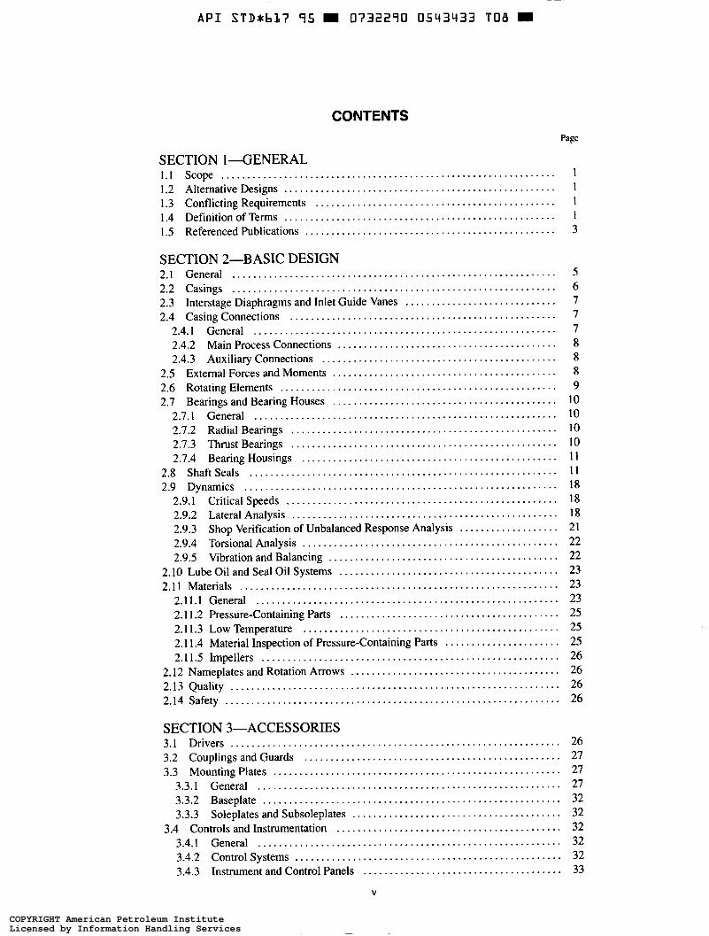
CONTENTS Page
SECTION 1-GENERAL 1.1 scope ................................................................ 1.2 Alternative Designs .................................................... 1 1.3 Conflicting Requirements .............................................. 1 1.4 Definition of Terms .................................................... 1 1.5 Referenced Publications ................................................ 3
1
SECTION 2-BASIC DESIGN 2.1 General .............................................................. 2.2 Casings .............................................................. 2.3 Interstage Diaphragms and Inlet Guide Vanes ............................. 2.4 Casing Connections ...................................................
2.4.1 General .......................................................... 2.4.2 Main Process Connections .......................................... 2.4.3 Auxiliary Connections .............................................
2.5 External Forces and Moments ........................................... 2.6 Rotating Elements ..................................................... 2.7 Bearings and Bearing Houses ...........................................
2.7.1 General .......................................................... 2.7.2 Radial Bearings ................................................... 2.7.3 Thrust Bearings ................................................... 2.7.4 Bearing Housings .................................................
2.8 Shaft Seals ........................................................... 2.9 Dynamics ............................................................
2.9.1 Critical Speeds .................................................... 2.9.2 Lateral Analysis ................................................... 2.9.3 Shop Verification of Unbalanced Response Analysis ................... 2.9.4 Torsional Analysis ................................................. 2.9.5 Vibration and Balancing ............................................
2.10 Lube Oil and Seal Oil Systems 2.1 1 Materials .............................................................
2.11.1 General ..........................................................
..........................................
2.1 1.2 Pressure-Containing Parts .......................................... 2.1 1.3 Low Temperature ................................................. 2.1 1.4 Material Inspection of Pressure-Containing Parts ...................... 2.1 1.5 Impellers .........................................................
2.12 Nameplates and Rotation Arrows ........................................ 2.13 Quality ............................................................... 2.14 Safety ................................................................
5 6 7 7 7 8 8 8 9
I O 10 10 IO 11 11 18 18 18 21 22 22 23 23 23 25 25 25 26 26 26 26
SECTION 3-ACCESSORIES 3.1 Drivers ............................................................... 3.2 Couplings and Guards ................................................. 3.3 Mounting Plates .......................................................
3.3.1 General .......................................................... 3.3.2 Baseplate ......................................................... 3.3.3 Soleplates and Subsoleplates ........................................
3.4 Controls and Instrumentation ........................................... 3.4.1 General .......................................................... 3.4.2 Control Systems ................................................... 3.4.3 Instrument and Control Panels ......................................
V
26 27 27 27 32 32 32 32 32 33
COPYRIGHT American Petroleum InstituteLicensed by Information Handling ServicesCOPYRIGHT American Petroleum InstituteLicensed by Information Handling Services

A P I STD*b17 95 = 0732290 0543434 944 =
3.4.4 Instrumentation ................................................... 33 3.4.5 Alarms and Shutdowns ............................................. 34 3.4.6 Electrical Systems ................................................. 35 3.4.7 Vibration, Position. and Bearing Temperature Detectors ................ 35
3.5 Piping and Appurtences ................................................ 35 3.5.1 General .......................................................... 35 3.5.2 Instrument Piping ................................................. 36 3.5.3 Process Piping .................................................... 36
3.6 Special Tools ......................................................... 36
SECTION GINSPECTION. TESTING. AND PREPARATION
4.1 General .............................................................. 36 4.2 Inspection ............................................................ 37
4.2.1 General .......................................................... 37 4.2.2 Material Inspection ................................................ 37
4.3 Testing ............................................................... 37 4.3.1 General .......................................................... 37 4.3.2 Hydrostatic Test ................................................... 38 4.3.3 Impeller Overspeed Test ........................................... 38 4.3.4 Mechanical Running Test .......................................... 38 4.3.5 Assembled Compressor Gas Leakage Test ............................ 39 4.3.6 Optional Tests .................................................... 40
4.4 Preparation for Shipment ............................................... 41
FOR SHIPMENT
SECTION 5-VENDOR'S DATA 5.1 General .............................................................. 42 5.2 Proposals ............................................................. 42
5.2.1 General .......................................................... 42 5.2.2 Drawings ......................................................... 42 5.2.3 Technical Data .................................................... 42 5.2.4 Curves ........................................................... 43 5.2.5 Options .......................................................... 44
5.3 ContractData ......................................................... 44 5.3.1 General .......................................................... 44 5.3.2 Drawings ......................................................... 44 5.3.3 Technical Data .................................................... 44 5.3.4 Progress Reports .................................................. 44 5.3.5 Recommended Spare Parts ......................................... 44 5.3.6 Installation, Operation, Maintenance. and Technical Data Manuals ...... 45
APPENDIX A-TYPICAL DATA SHEETS .................................. 47
COMPONENT PARTS ...................................... 61 APPENDIX C-CENTRIFUGAL COMPRESSOR VENDOR DRAWING
AND DATA REQUIREMENTS .............................. 67 APPENDIX D-PROCEDURE FOR DETERMINATION OF RESIDUAL
UNBALANCE ............................................. 79 APPENDIX E-ROTOR DYNAMIC LOGIC DIAGRAMS 85 APPENDIX F-CENTRIFUGAL COMPRESSOR NOMENCLATURE .......... 91 APPENDIX G-FORCES AND MOMENTS ................................. 95 APPENDIX H-INSPECTOR'S CHECKLIST ................................ 97 APPENDIX I-TYPICAL GAS SEAL TESTING CONSIDERATIONS .......... 101
MAGNETIC BEARINGS .................................... 103
APPENDIX B-TYPICAL MATERIAL SPECIFICATIONS FOR MAJOR
.....................
APPENDIX J-APPLICATION CONSIDERATIONS FOR ACTIVE
vi
COPYRIGHT American Petroleum InstituteLicensed by Information Handling ServicesCOPYRIGHT American Petroleum InstituteLicensed by Information Handling Services
A P I STDxbL7 95 0732290 0543435 880 =
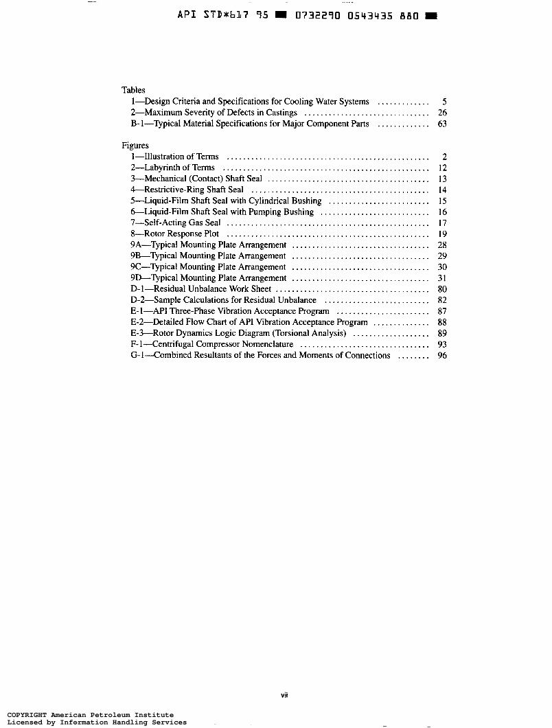
Tables 1-Design Criteria and Specifications for Cooling Water Systems ............. 5 2-Maximum Severity of Defects in Castings ............................... 26 B- 1-Typical Material Specifications for Major Component Parts ............. 63
Figures 1-Illustration of Terms .................................................. 2 2-Labyrinth of Terms ................................................... 12 3-Mechanical (Contact) Shaft Seal ........................................ 13 &Restrictive-Ring Shaft Seal ............................................ 14 5-Liquid-Film Shaft Seal with Cylindrical Bushing ......................... 15 6-Liquid-Film Shaft Seal with Pumping Bushing ........................... 16 7-Self-Acting Gas Seal .................................................. 17 8-Rotor Response Plot .................................................. 19 9A-Typical Mounting Plate Arrangement .................................. 28 9B-Typical Mounting Plate Arrangement .................................. 29 9C-Typical Mounting Plate Arrangement .................................. 30 9D-Typical Mounting Plate Arrangement .................................. 31 D-1-Residual Unbalance Work Sheet ...................................... 80 D-2-Sample Calculations for Residual Unbalance .......................... 82 E- 1-API Three-phase Vibration Acceptance Program ....................... 87
E-3-Rotor Dynamics Logic Diagram (Torsional Analysis) ................... 89 F- 1-Centrifugal Compressor Nomenclature ................................ 93
E-2-Detailed Flow Chart of API Vibration Acceptance Program .............. 88
G - l r o m b i n e d Resultants of the Forces and Moments of Connections ........ 96
COPYRIGHT American Petroleum InstituteLicensed by Information Handling ServicesCOPYRIGHT American Petroleum InstituteLicensed by Information Handling Services
~
API STDab17 95 W 0732290 0543436 717 W
Centrifugal Compressors for Petroleum, Chemical, and Gas Service Industries
SECTION 1-GENERAL
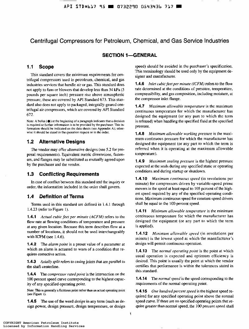
1.1 Scope This standard covers the minimum requirements for cen-
trifugal compressors used in petroleum, chemical, and gas industries services that handle air or gas. This standard does not apply to fans or blowers that develop less than 34 kPa (5 pounds per square inch) pressure rise above atmospheric pressure; these are covered by API Standard 673. This stan- dard also does not apply to packaged, integrally-geared cen- trifugal air compressors, which are covered by API Standard 672. Note: A bullet (0 ) at the beginning of a paragraph indicates that a decision is required or further information is to be provided by the purchaser. This in- formation should be indicated on the data sheets (see Appendix A); other- wise it should be stated in the quotation request or in the order.
1.2 Alternative Designs The vendor may offer alternative designs (see 5.2 for pro-
posal requirements). Equivalent metric dimensions, fasten- ers, and flanges may be substituted as mutually agreed upon by the purchaser and the vendor.
speed) should be avoided in the purchaser's specification. This terminology should be used only by the equipment de- signer and manufacturer.
1.4.6 Inlet cubic feet per minute (ICFM) refers to the flow rate determined at the conditions of pressure, temperature, compressibility, and gas composition, including moisture, at the compressor inlet flange.
1.4.7 Maximum allowable temperature is the maximum continuous temperature for which the manufacturer has designed the equipment (or any part to which the term is referred) when handling the specified fluid at the specified pressure.
1.4.8 Maximum allowable working pressure is the maxi- mum continuous pressure for which the manufacturer has designed the equipment (or any part to which the term is referred when it is operating at the maximum allowable temperature).
1.4.9 Maximum sealing pressure is the highest pressure expected at the seals during any specified static or operating conditions and during startup or shutdown.
1.4.10 Maximum continuous speed (in revolutions per minute) for compressors driven by variable-speed prime movers is the speed at least equal to 105 percent of the high-
1.3 Conflicting Requirements In case of conflict between this standard and the inquiry or
order, the information included in the order shall govern.
1.4 Definition of Terms Terms used in this standard are defined in 1.4.1 through
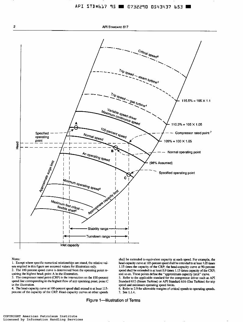
1.4.23 (refer to Figure I ).
1.4.1 Actual cubic feet per minute (ACFMI refers to the flow rate at flowing conditions of temperature and pressure at any given location. Because this term describes flow at a number of locations, it should not be used interchangeably with ICFM (see 1.4.6).
1.4.2 The alarm point is a preset value of a parameter at which an alarm is actuated to warn of a condition that re- quires corrective action.
1.4.3 Axially split refers to casing joints that are parallel to the shaft centerline.
1.4.4 The compressor rated point is the intersection on the 100 percent speed curve corresponding to the highest capac- ity of any specified operating point.
est speed required by any of the specified operating condi- tions. Maximum continuous speed for constant-speed drivers shall be equal to the 100 percent speed.
1.4.11 Minimum allowable temperature is the minimum continuous temperature for which the manufacturer has designed the equipment (or any part to which the term is applied).
1.4.1 2 Minimum allowable speed (in revolutions per minute) is the lowest speed at which the manufacturer's design will permit continuous operation.
1.4.13 The normal operating point is the point at which usual operation is expected and optimum efficiency is desired. This point is usually the point at which the vendor certifies that performance is within the tolerances stated in this standard.
1.4.1 4 requirements of the normal operating point.
The normal speed is the speed corresponding to the
Note: "%is iS geIIerdly a fictitious point rather than an actual operating point (see Figure i).
1.4.5 The use of the word design in any term (such as de- sign power, design pressure, design temperature, or design
1.4.1 5 One hundred percent speed is the highest speed re- quired for any specified operating point above the normal speed curve. If there are no specified operating points that re- quire greater than normal speed, the 100 percent speed shall
1
COPYRIGHT American Petroleum InstituteLicensed by Information Handling ServicesCOPYRIGHT American Petroleum InstituteLicensed by Information Handling Services
-~
A P I STD*bL7 95 0732290 0543437 653
2 API STANDARD 61 7
I I- Stability range II I I I I i+- Turndown range I I I I I
Inlet capacity
Notes: 1. Except where specific numerical relationships are stated, the relative val- ues implied in this figure are assumed values for illustration only. 2. The 100 percent speed curve is determined from the operating point re- quiring the highest head; point A in the illustration. 3. The compressor rated point (CRP) is the intersection on the 100-percent speed line corresponding to the highest flow of any operating point; point C in the illustration. 4. The head-capacity curve at 100-percent speed shall extend to at least 115- percent of the capacity of the CRP. Head-capacity curves at other speeds
shall be extended to equivalent capacity at each speed. For example, the head-capxity curve at 105-percent speed shall be extended to at least 1.05 times 1.15 times the capacity of the CRP, the head-capacity curve at %-percent speed shall be extended to at least 0.9 times 1.15 times capacity of the CRP, and so on. These points define the “approximate capacity h i t ” curve. 5. Refer to the applicable standard for the compressor driver such as API Standard 612 (Steam Turbine) or API Standard 616 (Gas Turbine) for trip speed and minimum operating speed limits. 6. Refer to 2.9 for allowable margins of critical speeds to operating speeds. 7. See 1.1.4.
Figure 1-Illustration of Terms
COPYRIGHT American Petroleum InstituteLicensed by Information Handling ServicesCOPYRIGHT American Petroleum InstituteLicensed by Information Handling Services
A P I S T D x b l 7 95 W 0732290 0543438 59T W
CENTRIFUGAL COMPRESSORS FOR PETROLEUM, CHEMICAL, AND GAS SERVICE INDUSTRIES 3
be the normal speed. For motor-driven compressors, the i00 percent speed shall be equal to the gear ratio (if any) times the full load speed of the motor being furnished.
1.4.1 6 Radially split refers to casing joints that are trans- verse to the shaft centerline.
1.4.1 7 Settling out pressure is the pressure of the com- pressor system when the compressor is shut down.
1.4.18 Shutdown point is a preset operational value of a parameter at which automatic or manual shutdown of the system is required.
1.4.19 Stability is the difference in capacity (in percent of rated capacity) between the rated capacity and the surge point at rated speed (and rated gas properties).
1.4.20 Standard cubic feet per minute (SCFM) refers to the flow rate at any location corrected to a pressure at 14.7 pounds per square inch absolute (1 .O1 bar) and a temperature of 60°F (15.56OC) with a compressibility factor of 1 .O and in a dry condition.
1.4.21 Trip speed (in revolutions per minute) is the speed at which the independent emergency overspeed device oper- ates to shut down a prime mover.
1.4.22 Turndown is the percentage of change in capacity (referred to rated capacity) between the rated capacity and the surge point capacity at the rated head when the unit is op- erating at rated suction temperature and gas composition.
1.4.23 Unit responsibility refers to the responsibility for coordinating the technical aspects of the equipment and ali auxiliary systems included in the scope of the order. Responsibility for such factors as the power requirements, speed, rotation, piping, and testing of components shall be reviewed.
1.5 Referenced Publications 1.5.1 The editions of the following standards, codes, and specifications that are in effect at the time of publication of this standard shall, to the extent specified herein, form a part of this standard. The applicability of changes in standards, codes, and specifications that occur after the inquiry shall be mutually agreed upon by the purchaser and the vendor.
ANSI‘ B 1.20.3
B 16.1
B 16.5
B 16.11
Dryseal Pipe Threads (Inch) Cast Iron Pipe Flanges and Flanged Fit- tings, Class 25,125,250, and 800 Pipe Flanges and Flanged Fittings, Steel Nickel Alloy and Other Special Alloys Forged Steel Fittings, Socket- Welding and Threaded
‘Amencan Nationai Standards Institute, 11 West 42nd Street, New York, New York 10036.
Bi 6.42
B19.3
S18.1
Std 541
Std 546
Std 612
Std 61 3
API
Std 614
Std 616 Std 670
Std 671
Std 672
Std 673
RP 683
ASME2 B1.l
B1.20.1 B 16.47
B31.3
PTC 10 PTC 1
Ductile Iron Pipe Flanges and Flanged Fittings, Class 150 and 300 Safety Standards for Compressors for General Refinery Services Annunciator Sequences and Speciifications
Form- Wound Squirrel-Cage Induction Motors-250 Horsepower and Larger Form- Wound Brushless Synchronous Motors-500 Horsepower and Larger Special-Purpose Steam Turbines for Re- finery Services Special-Purpose Gear Units for Refinery Service Lubrication, S.fi-Sealing, and Control-Oil Systems for Special-Purpose Applications Gas Turbines for Refinery Services Vibration, Axial-Position, and Bearing- Temperature Monitoring Systems Special-Purpose Couplings for Refinery Service Packaged, Integrally Geared, Centrifugal Air Compressors for General Refinery Service Special-Purpose Centrifugal Fans for General Refnery Service (under develop- ment) Quality Improvement Manual for Me- chanical Equipment in Petroleum, Chem- ical, and Gas Industries
Unified Inch Screw Threads (UN and UNR Thread Form) General Purpose (Inch) Pipe Threads Large-Diameter Carbon Steel Flanges (Nominal Pipe Sizes 26 Through 60; Classes 75,150,300,400,600, and 900) Chemical Plant and Petroleum Refinery Piping Compressors and Exhausters General Instructions
Boiler and Pressure Vessel Code, Section VIII, “Rules for Construction of Pressure Vessels,” and Section IX, “Welding and Brazing Qualifications”
ASTM3 A 48
A 148 Gray Iron Castings High-Strength Steel Castings for Struc- tural Purposes
*Amencan Society of Mechanical Engineers, 345 East 47th Street, New York, New York 10017. ’Amencan Society for Testing and Materials, 1916 Race Street, Philadel- phia, Pennsylvania 19103-1187.
COPYRIGHT American Petroleum InstituteLicensed by Information Handling ServicesCOPYRIGHT American Petroleum InstituteLicensed by Information Handling Services
A P I STDxbL7 95 0732290 0543439 426
4 API STANDARD 61 7
A 193
A 194
A 203 A 216
A 217
A 240
A 266
A 278
A 283
A 284
A 285
A 307
A 320
A 336
A 351
A 352
A 353
A 367 A 370
A 388
A 395
A 414 A 436 A 470
A 473 A 494
Alloy Steel and Stainless Steel Bolting Materials for High-Temperature Service Carbon and Alloy Steel Nuts for Bolts for High-pressure and High-Temperature Service Pressure Vessel Plates, Alloy Steel, Nickel Carbon-Steel Castings Suitable for Fusion Welding for High-Temperature Service Martensitic Stainless Steel and Alloy Steel Castings for Pressure-Containing Parts Suitable for High-Temperature Service Heat-Resisting Chromium and Chromium- Nickel Stainless Steel Plate, Sheet, and Strip for Pressure Vessels Carbon Steel Forgings for Pressure Ves- sels Components Gray Iron Casting for Pressure-Contain- ing Parts for Temperatures Up to 650°F (345°C) Low and Intermediate Tensile Strength Carbon Steel Plates, Shapes, and Bars Low and Intermediate Tensile Strength Carbon Silicon Steel Plates for Machine Parts and General Construction Low-and Intermediate-Tensile Strength Carbon Steel Pressure Vessel Plates Carbon Steel Externally Threaded Stan- dard Fasteners Alloy-Steel Bolting Materials for Low- Temperature Service Alloy Steel Forgings for Pressure and High Temperature Parts Austenitic Steel Castings for High Tem- perature Service Ferritic and Martensitic Steel Castings for Pressure-Containing Parts Suitable for Low Temperature Service Double-Normalized and Tempered 9 Per- cent Nickel Alloy Steel Pressure Vessel Plates Chill Testing of Cast Iron Methods and Definitions for Mechanical Testing of Steel Products Practice for Ultrasonic Examination of Heavy Steel Forgings Ferritic Ductile Iron Pressure Retaining Castings for Use at Elevated Temperatures Carbon Steel Sheet for Pressure Vessels Austenitic Gray Iron Castings Vacuum-Treated Carbon and Alloy Steel Forgings for Turbine Rotors and Shafs Stainless and Heat-Resisting Steel Forgings Nickel and Nickel Alloy Castings
A 515
A 522
A 536 A 537
A 543
A 553
A571
A 578
A 609
A 693
A 705
A 709 A 743
A 744
A 747
B 23 B 26 B 29
B 127
B 164 B 367 B 462
B 574
DS56C
Carbon Steel Pressure Vessel Plates for Moderate and Lower Temperature Service Forged or Rolled 8 and 9 Percent Nickel Alloy Steel Flanges, Fittings, Valves, and Parts for Low-Temperature Service Ductile Iron Castings Carbon Manganese-Silicon Heat Treated Pressure Vessel Plates Quenched and Tempered Nickel-Chromium- Molybdenum Alloy Steel Pressure Vessel Plates Quenched and Tempered 8 and 9 Percent Nickel Alloy Steel Pressure Vessel Plates Austenitic Ductile Iron Casting for Pres- sure-Containing Parts Suitable for Low Temperature Service Specification for Ultrasonic Angle-beam Examination of Steel Plates Practice for Castings, Carbon, Low- Alloy, and Martensitic Stainless Steel, Ultrasonic Examination Thereof Precipitation-Hardening Stainless and Heat-Resisting Steel Plate, Sheet, and Strip Age-Hardening Stainless and Heat- Resisting Steel Forgings Structural Steel for Bridges Iron-Chromium, Iron-Chromium-Nickel, and Nickel-Base Corrosion-Resistant Castings for General Application Iron-Chromium-Nickel and Nickel-Base Corrosion-Resistant Castings for Severe Service Precipitation Hardening Stainless Steel Castings White Metal Bearing Alloys Aluminum-Alloy Sand Castings Pig Lead Nickel-Copper Alloy Plate, Sheet, and Strip Nickel-Copper Alloy Rod, Bar, and Wire Titanium and Titanium Alloy Castings Forged or Rolled Chromium-Nickel-Iron Molybdenum-Copper-Columbian Stabi- lized Alloy Pipe Flanges, Forged Fittings, and Valves and Parts for Corrosive High Temperature Service Low-Carbon Nickel-Molybdenum-Chro- mium Alloy Rod Metals and Alloys in the Unified Number- ing System
COPYRIGHT American Petroleum InstituteLicensed by Information Handling ServicesCOPYRIGHT American Petroleum InstituteLicensed by Information Handling Services
A P I S T D r b L ï 95 0732290 0543440 148 =
CENTRIFUGAL COMPRESSORS FOR PETROLEUM, CHEMICAL, ANO GAS SERVICE INDUSTRIES 5
E 94 E 125
E 165
E 709
Guide for Radiographic Testing Reference Photographs for Magnetic Particle Indications on Ferrous Castings Practice for Liquid Penetrant Inspection Method Practice for Magnetic Particle Examination
AWS4 Structural Welding Code - Steel
ISA~ S 18.1 Annunciator Sequences and SpecGcations
MSS6 SP-44 Steel Pipe Line Flanges
NACE7 MRO175-93 Sulfide Stress Cracking Resistant Metallic
Material for Oil Field Equipment
4American Welding Society, 550 N.W. LeJeune Road, Miami, Florida 33135. sInstniment Society of America, P.O. Box 12277, Research Triangle Park, North Carolina, 27709. 6Manufacturers Standardization Society of the Valve and Fittings Industry, 127 Park Street, N.E., Vienna, Virginia 22180. 'National Association of Corrosion Engineers, P.O. Box 218340, Houston, Texas 77218.
NFPA' 70
496
National Electrical Code, Articles 500, 501, and 502 Purged and Pressurized Enclosures for Electrical Equipment
SAE9
SSPCIO
U.S. Government Specifications
(UNS NOSSO)
AMS 4676 Bars and Forgings
SP6 Commercial Blast Cleaning
QQ-N-286 Wrought Nickel-Copper-Aluminum Alloy
1 S.2 The purchaser and the vendor shall mutually deter- mine the measures that must be taken to comply with any governmental regulations, ordinances, or rules that are appli- cable to the equipment.
*National Fire Protection Association, 1 Batterymarch Park, Quincy, Mas- sachusetts 02269-9101. 9Society of Automotive Engineers, 400 Commonwealth Drive, Warrendale, Pennsylvania 15096-000 1. "Steel Structures Painting Council, 44'20 Fifth Avenue, Pittsburgh, Pennsyl- vania 15213-2683.
SECTION 2-BASIC DESIGN
2.1 General 2.1.1 The equipment (including auxiliaries) covered by this standard shall be designed and constructed for a minimum service life of 20 years and at least 3 years of uninterrupted operation. Note: It is recognized that this is a design criterion.
2.1.2 Unless otherwise specified, the compressor vendor shall assume unit responsibility for all equipment and all auxiliary systems included in the scope of the order.
2.1.3 Unless otherwise specified, the compressor shall be designed to deliver normal head and normal capacity without negative tolerance. The horsepower at the above condition shall not exceed 104 percent of the normal value. Note: See the optional performance test criteria in 4.3.6.1, and handling of excess head for constant speed drivers.
2.1.4 The head-capacity characteristic curve shall rise continuously from the rated point to predicted surge. The compressor, without the use of a bypass, shall be suitable for continuous operation at any capacity at least 10 percent greater than the predicted approximate surge capacity shown in the proposal.
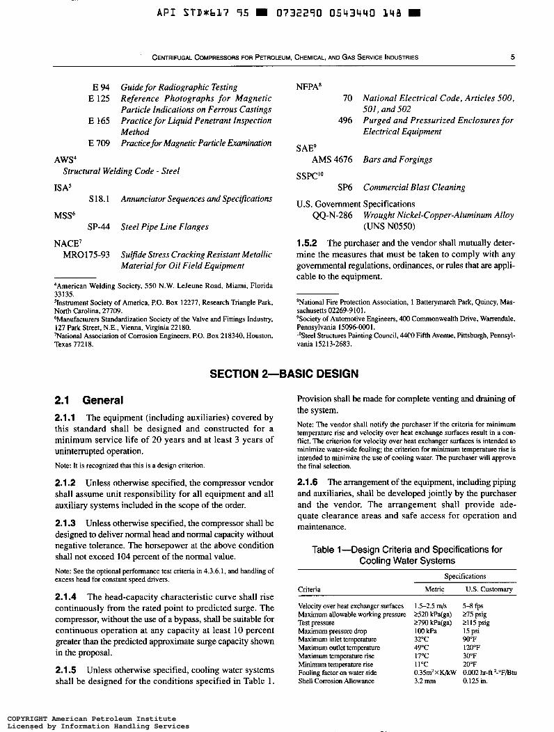
2.1.5 Unless otherwise specified, cooling water systems shall be designed for the conditions specified in Table 1 .
Provision shall be made for complete venting and draining of the system. Note: The vendor shall notify the purchaser if the criteria for minimum temperature rise and velocity over heat exchange surfaces result in a con- flict. The criterion for velocity over heat exchanger surfaces is intended to minimize water-side fouling; the criterion for minimum temperature rise is intended to minimize the use of cooling water. The purchaser will approve the final selection.
2.1.6 The arrangement of the equipment, including piping and auxiliaries, shall be developed jointly by the purchaser and the vendor. The arrangement shall provide ade- quate clearance areas and safe access for operation and maintenance.
Table 1 -Design Criteria and Specifications for Cooling Water Systems
Criteria
Specifications
Metric U.S. Customary
Velocity over heat exchanger surfaces Maximum allowable working pressure Test pressure Maximum pressure drop Maximum inlet temperature Maximum outlet temperature Maximum temperature rise Minimum temperature rise Fouling factor on water side Shell Corrosion Allowance
1.5-2.5 m/s 5-8 fps 2520 kPa(ga) 275 psig 2790 kPa(ga) 2115 psig 100 kPa 15 psi 32°C 900F 49°C 120°F 17°C 30°F l l0C 20°F 0.35mZXK/kW 0.002 hr-fi 2-"F/Btu 3.2 mm 0.125 in.
COPYRIGHT American Petroleum InstituteLicensed by Information Handling ServicesCOPYRIGHT American Petroleum InstituteLicensed by Information Handling Services
API STDrb17 95 m 0732290 0543443 084 m
6 API STANDARD 61 7
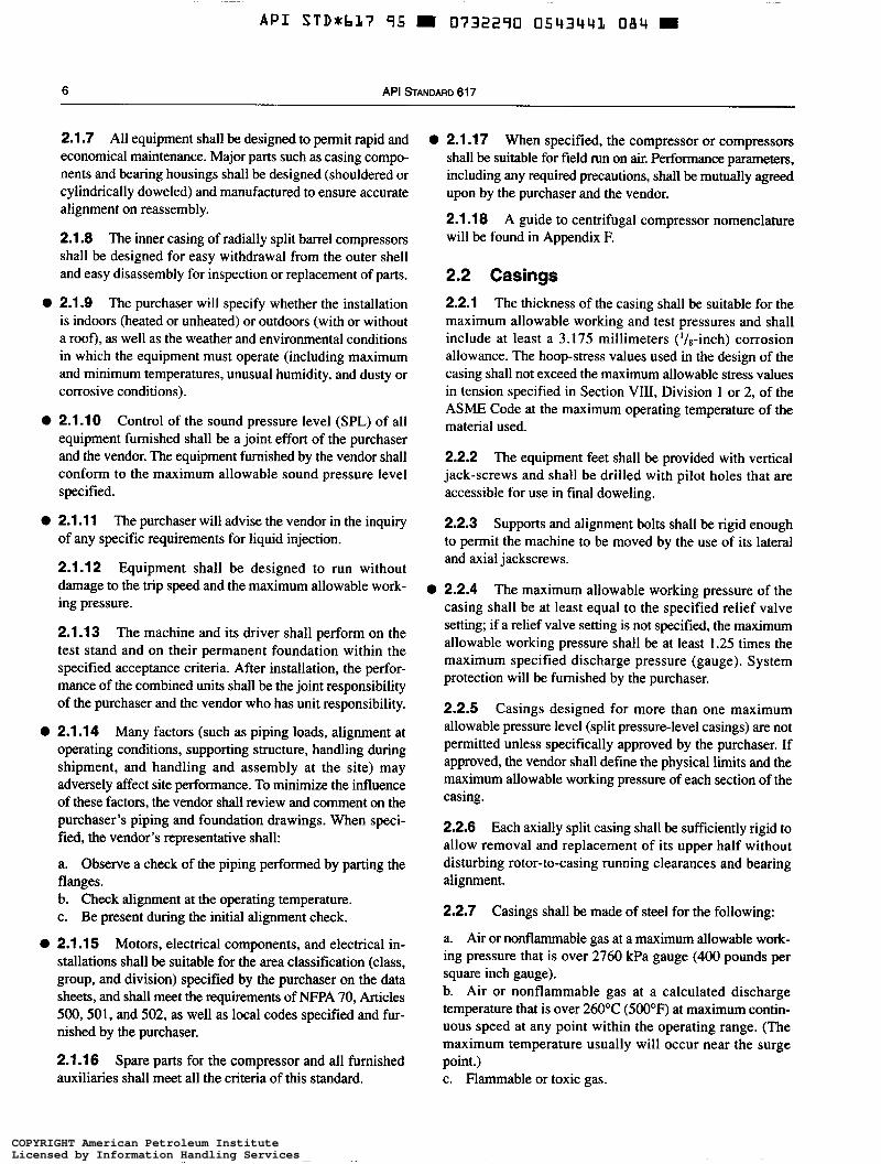
2.1.7 All equipment shall be designed to permit rapid and economical maintenance. Major parts such as casing compo- nents and bearing housings shall be designed (shouldered or cylindrically doweled) and manufactured to ensure accurate alignment on reassembly.
2.1.8 The inner casing of radially split barrel compressors shall be designed for easy withdrawal from the outer shell and easy disassembly for inspection or replacement of parts.
The purchaser will specify whether the installation is indoors (heated or unheated) or outdoors (with or without a roof), as well as the weather and environmental conditions in which the equipment must operate (including maximum and minimum temperatures, unusual humidity, and dusty or corrosive conditions).
O 2.1.9
O 2.1.1 O Control of the sound pressure level (SPL) of all equipment furnished shall be a joint effort of the purchaser and the vendor. The equipment furnished by the vendor shall conform to the maximum allowable sound pressure level Specified.
O 2.1.1 1 The purchaser will advise the vendor in the inquiry of any specific requirements for liquid injection.
2.1.12 Equipment shall be designed to run without damage to the trip speed and the maximum allowable work- ing pressure.
2.1.1 3 The machine and its driver shall perform on the test stand and on their permanent foundation within the specified acceptance criteria. After installation, the perfor- mance of the combined units shall be the joint responsibility of the purchaser and the vendor who has unit responsibility.
Many factors (such as piping loads, alignment at operating conditions, supporting structure, handling during shipment, and handling and assembly at the site) may adversely affect site performance. To minimize the influence of these factors, the vendor shall review and comment on the purchaser's piping and foundation drawings. When speci- fied, the vendor's representative shall:
a. Observe a check of the piping performed by parting the flanges. b. Check alignment at the operating temperature. c. Be present during the initial alignment check.
O 2.1.14
O 2.1.1 5 Motors, electrical components, and electrical in- stallations shall be suitable for the area classification (class, group, and division) specified by the purchaser on the data sheets, and shall meet the requirements of NFPA 70, Articles 500,501, and 502, as well as local codes specified and fur- nished by the purchaser.
2.1.1 6 Spare parts for the compressor and all furnished auxiliaries shall meet all the criteria of this standard.
O 2.1.1 7 When specified, the compressor or compressors shall be suitable for field run on air. Performance parameters, including any required precautions, shall be mutually agreed upon by the purchaser and the vendor.
2.1.18 A guide to centrifugal compressor nomenclature will be found in Appendix E
2.2 Casings 2.2.1 The thickness of the casing shall be suitable for the maximum allowable working and test pressures and shall include at least a 3.175 millimeters ('/8-inch) corrosion allowance. The hoop-stress values used in the design of the casing shall not exceed the maximum allowable stress values in tension specified in Section VIII, Division 1 or 2, of the ASME Code at the maximum operating temperature of the material used.
2.2.2 The equipment feet shall be provided with vertical jack-screws and shall be drilled with pilot holes that are accessible for use in final doweling.
2.2.3 Supports and alignment bolts shall be rigid enough to permit the machine to be moved by the use of its lateral and axial jackscrews.
O 2.2.4 The maximum allowable working pressure of the casing shall be at least equal to the specified relief valve setting; if a relief valve setting is not specified, the maximum allowable working pressure shall be at least 1.25 times the maximum specified discharge pressure (gauge). System protection will be furnished by the purchaser.
2.2.5 Casings designed for more than one maximum allowable pressure level (split pressure-level casings) are not permitted unless specifically approved by the purchaser. If approved, the vendor shall define the physical limits and the maximum allowable working pressure of each section of the casing.
2.2.6 Each axially split casing shall be sufficiently rigid to allow removal and replacement of its upper half without disturbing rotor-to-casing running clearances and bearing alignment.
2.2.7 Casings shall be made of steel for the following:
a. Air or nonflammable gas at a maximum allowable work- ing pressure that is over 2760 kPa gauge (400 pounds per square inch gauge). b. Air or nonflammable gas at a calculated discharge temperature that is over 260°C (500°F) at maximum contin- uous speed at any point within the operating range. (The maximum temperature usually will occur near the surge point.) c. Flammable or toxic gas.
COPYRIGHT American Petroleum InstituteLicensed by Information Handling ServicesCOPYRIGHT American Petroleum InstituteLicensed by Information Handling Services
A P I STD+bL7 95 0732290 0543442 TLO =
CENTRIFUGAL COMPRESSORS FOR PETROLEUM, CHEMICAL, AND GAS SERVICE INDUSTRIES 7
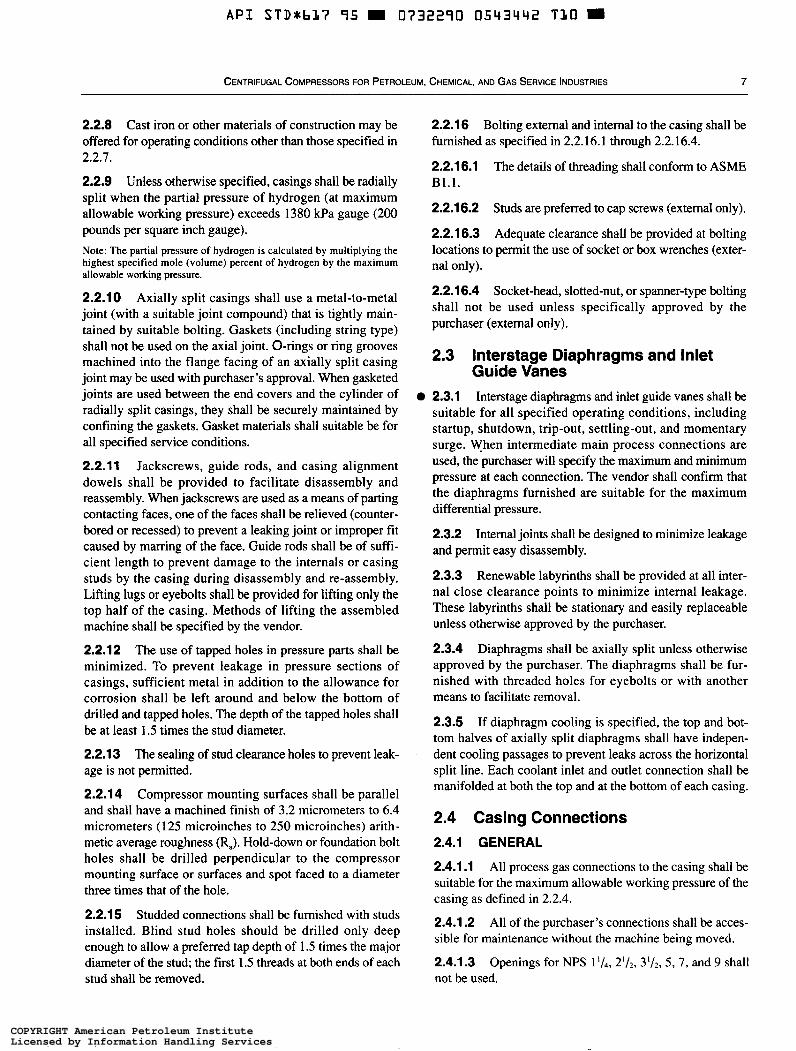
2.2.8 Cast iron or other materials of constmction may be offered for operating conditions other than those specified in 2.2.7.
2.2.9 Unless otherwise specified, casings shall be radially split when the partial pressure of hydrogen (at maximum allowable working pressure) exceeds 1380 kPa gauge (200 pounds per square inch gauge). Note: The partial pressure of hydrogen is calculated by multiplying the highest specified mole (volume) percent of hydrogen by the maximum allowable working pressure.
2.2.10 Axially split casings shall use a metal-to-metal joint (with a suitable joint compound) that is tightly main- tained by suitable bolting. Gaskets (including string type) shall not be used on the axial joint. O-rings or ring grooves machined into the flange facing of an axially split casing joint may be used with purchaser’s approval. When gasketed joints are used between the end covers and the cylinder of radially split casings, they shall be securely maintained by confining the gaskets. Gasket materials shall suitable be for all specified service conditions.
2.2.1 1 Jackscrews, guide rods, and casing alignment dowels shall be provided to facilitate disassembly and reassembly. When jackscrews are used as a means of parting contacting faces, one of the faces shall be relieved (counter- bored or recessed) to prevent a leaking joint or improper fit caused by marring of the face. Guide rods shall be of suffi- cient length to prevent damage to the internals or casing studs by the casing during disassembly and re-assembly. Lifting lugs or eyebolts shall be provided for lifting only the top half of the casing. Methods of lifting the assembled machine shall be specified by the vendor.
2.2.12 The use of tapped holes in pressure parts shall be minimized. To prevent leakage in pressure sections of casings, sufficient metal in addition to the allowance for corrosion shall be left around and below the bottom of drilled and tapped holes. The depth of the tapped holes shall be at least 1.5 times the stud diameter.
2.2.1 3 The sealing of stud clearance holes to prevent leak- age is not permitted.
2.2.1 4 Compressor mounting surfaces shall be parallel and shall have a machined finish of 3.2 micrometers to 6.4 micrometers ( 1 25 microinches to 250 microinches) arith- metic average roughness (Ra). Hold-down or foundation bolt holes shall be drilled perpendicular to the compressor mounting surface or surfaces and spot faced to a diameter three times that of the hole.
2.2.15 Studded connections shall be furnished with studs installed. Blind stud holes should be drilled only deep enough to allow a preferred tap depth of 1.5 times the major diameter of the stud; the first 1.5 threads at both ends of each stud shall be removed.
2.2.1 6 furnished as specified in 2.2.16.1 through 2.2.16.4.
2.2.1 6.1 B1.l.
Bolting external and internal to the casing shall be
The details of threading shall conform to ASME
2.2.16.2 Studs are preferred to cap screws (external only).
2.2.1 6.3 Adequate clearance shall be provided at bolting locations to permit the use of socket or box wrenches (exter- nal only).
2.2.1 6.4 Socket-head, slotted-nut, or spanner-type bolting shall not be used unless specifically approved by the purchaser (extemal only).
2.3 Interstage Diaphragms and Inlet Guide Vanes
O 2.3.1 Interstage diaphragms and inlet guide vanes shall be suitable for all specified operating conditions, including startup, shutdown, trip-out, settling-out, and momentary surge. When intermediate main process connections are used, the purchaser will specify the maximum and minimum pressure at each connection. The vendor shall confirm that the diaphragms furnished are suitable for the maximum differential pressure.
2.3.2 Internal joints shall be designed to minimize leakage and permit easy disassembly.
2.3.3 Renewable labyrinths shall be provided at all inter- nal close clearance points to minimize internal leakage. These labyrinths shall be stationary and easily replaceable unless otherwise approved by the purchaser.
2.3.4 Diaphragms shall be axially split unless otherwise approved by the purchaser. The diaphragms shall be fur- nished with threaded holes for eyebolts or with another means to facilitate removal.
2.3.5 If diaphragm cooling is specified, the top and bot- tom halves of axially split diaphragms shall have indepen- dent cooling passages to prevent leaks across the horizontal split line. Each coolant inlet and outlet connection shall be manifolded at both the top and at the bottom of each casing.
2.4 Casing Connections 2.4.1 GENERAL
2.4.1.1 All process gas connections to the casing shall be suitable for the maximum allowable working pressure of the casing as defined in 2.2.4.
2.4.1.2 sible for maintenance without the machine being moved.
2.4.1.3 not be used.
All of the purchaser’s connections shall be acces-
Openings for NPS 1’/4, 21/2, 3’/2, 5 , 7, and 9 shall
COPYRIGHT American Petroleum InstituteLicensed by Information Handling ServicesCOPYRIGHT American Petroleum InstituteLicensed by Information Handling Services
~
A P I STD*bL7 95 m 0732290 0 5 4 3 4 4 3 957 m
a API STANDARD 61 7
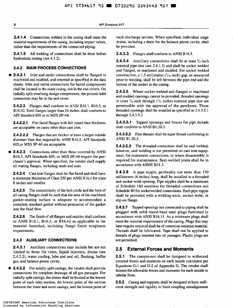
2.4.1.4 Connections welded to the casing shall meet the material requirements of the casing, including impact values, rather than the requirements of the connected piping.
2.4.1.5 All welding of connections shall be done before hydrostatic testing (see 4.3.2).
2.4.2 MAIN PROCESS CONNECTIONS
2.4.2.1 Inlet and outlet connections shall be flanged or machined and studded, and oriented as specified in the data sheets. Inlet and outlet connections for barrel compressors shall be located in the outer casing, not in the end covers. On radially split overhung design compressors, the process inlet connection may be in the end cover.
2.4.2.2 Flanges shall conform to ANSI B 16.1, B 16.5, or B 16.42. Steel flanges larger than 24 inches shall conform to API Standard 605 or to MSS SP-44.
2.4.2.2.1 are acceptable on cases other than cast iron.
2.4.2.2.2 Flanges that are thicker or have a larger outside diameter than that required by ANSI B 16.5, API Standards 605,or MSS SP-44 are acceptable.
2.4.2.3 Connections other than those covered by ANSI B 16.5, API Standards 605, or MSS SP-44 require the pur- chaser's approval. When specified, the vendor shall supply all mating flanges, including studs and nuts.
2.4.2.4 Cast iron flanges shall be flat faced and shall have a minimum thickness of Class 250 per ANSI B 16.1 for sizes 8 inches and smaller.
2.4.2.5 The concentricity of the bolt circle and the bore of all casing flanges shall be such that the area of the machined gasket-seating surface is adequate to accommodate a complete standard gasket without protrusion of the gasket into the fluid flow.
2.4.2.6 The finish of all flanges and nozzles shall conform to ANSI B 16.1, B 16.5, or B 16.42 as applicable to the material furnished, including flange finish roughness requirements.
Flat-faced flanges with full raised-face thickness
2.4.3 AUXILIARY CONNECTIONS
2.4.3.1 Auxiliary connections may include but are not limited to those for vents, liquid injection, drains (see 2.4.3.2), water cooling, lube and seal oil, flushing, buffer gas, and balance piston cavity.
2.4.3.2 For axially split casings, the vendor shall provide connections for complete drainage of all gas passages. For radially split casings, the drains shall be located at the lowest point of each inlet section, the lowest point of the section between the inner and outer casings, and the lowest point of
each discharge section. When specified, individual stage drains, including a drain for the balance piston cavity, shall be provided.
2.4.3.3 Flanges shall conform to ANSI B 16.5.
2.4.3.4 Auxiliary connections shall be at least 3/4-inch nominal pipe size (see 2.4.1.3) and shall be socket welded and flanged, or machined and studded. For socket welded construction, a 1.5-millimeter ('/16-inch) gap, as measured prior to welding, shall be left between the pipe end and the bottom of the socket in the casing.
2.4.3.5 Where socket-welded and flanged or machined and studded openings cannot be provided, threaded openings in sizes 3/4-in~h through 1 inches nominal pipe size are permissible with the approval of the purchaser. These threaded openings shall be installed as specified in 2.4.3.5.1 through 2.4.3.5.3
2.4.3.5.1 Tapped openings and bosses for pipe threads shall conform to ANSI B 1.20.3.
2.4.3.5.2 Pipe threads shall be taper thread conforming to ANSI B 1.20.3.
2.4.3.5.3 The threaded connection shall be seal welded; however, seal welding is not permitted on cast iron equip- ment, for instrument connections, or where disassembly is required for maintenance. Seal-welded joints shall be in accordance with ASME B3 1.3.
2.4.3.6 A pipe nipple, preferably not more than 150 millimeters (6 inches) long, shall be installed in a threaded and socket-weld opening. Pipe nipples shall be a minimum of Schedule 160 seamless for threaded connections and Schedule 80 for socketwelded connections. Each pipe nipple shall be provided with a welding-neck, socket-weld, or slip-on flange.
2.4.3.7 Tapped openings not connected to piping shall be plugged with solid round-head steel plugs furnished in accordance with ANSI B 16,ll. As a minimum plugs shall meet the material requirements of the casing. Plugs that may later require removal shall be of corrosion-resistant material. Threads shall be lubricated. Tape shall not be applied to threads of plugs inserted into oil passages. Plastic plugs are not permitted.
2.5 External Forces and Moments 2.5.1 The compressor shall be designed to withstand external forces and moments on each nozzle calculated per Equations G-1 and G-2 of Appendix G. The vendor shall furnish the allowable forces and moments for each nozzle in tabular form.
2.5.2 Casing and supports shall be designed to have suffi- cient strength and rigidity to limit coupling misalignment
COPYRIGHT American Petroleum InstituteLicensed by Information Handling ServicesCOPYRIGHT American Petroleum InstituteLicensed by Information Handling Services
A P I STD*bl7 95 m 0732290 054344Y 893
CENTRIFUGAL COMPRESSORS FOR PETROLEUM, CHEMICAL, AND GAS SERVICE INDUSTRIES 9
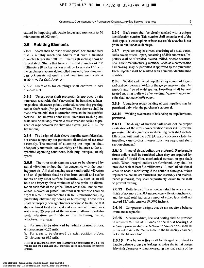
caused by imposing allowable forces and moments to 50 micrometers (0.002 inch).
2.6 Rotating Elements 2.6.1 Shafts shall be made of one-piece, heat treated steel that is suitably machined. Shafts that have a finished diameter larger than 203 millimeters (8 inches) shall be forged steel. Shafts that have a finished diameter of 203 millimeters (8 inches) or less shall be forged steel or, with the purchaser’s approval, hot rolled barstock, providing such barstock meets all quality and heat treatment criteria established for shaft forgings.
2.6.2 Shaft ends for couplings shall conform to API Standard 67 1.
2.6.3 Unless other shaft protection is approved by the purchaser, renewable shaft sleeves shall be furnished at inter- stage close-clearance points, under all carbon-ring packing, and at shaft seals (for gas service). These sleeves shall be made of a material that is corrosion-resistant in the specified service. The sleeves under close-clearance bushing end seals shall be suitably treated to resist wear and sealed to pre- vent leakage between the shaft and sleeve (see 2.1 1.1.7 for limitations).
2.6.4 The design of shaft-sleeve-impeller assemblies shall not create temporary nor permanent distortions of the rotor assembly. The method of attaching the impeller shall adequately maintain concentricity and balance under all specified operating conditions, including overspeed to trip speed.
2.6.5 The rotor shaft sensing areas to be observed by radial-vibration probes shall be concentric with the bear- ing journals. All shaft sensing areas (both radial vibration and axial position) shall be free from stencil and scribe marks or any other surface discontinuity, such as an oil hole or a keyway, for a minimum of one probe-tip diame- ter on each side of the probe. These areas shall not be met- alized, sleeved, or plated. The final surface finish shall be from 0.4 to 0.8 micrometer (16 to 32 microinches) Ra, preferably obtained by honing or burnishing. These areas shall be properly demagnetized or otherwise treated so that the combined total electrical and mechanical runout does not exceed 25 percent of the maximum allowed peak-to- peak vibration amplitude or the following value, whichever is greater:
a. For areas to be observed by radial vibration probes, 6 micrometers (0.25 mil). b. For areas to be observed by axial position probes, 13 micrometers (0.5 mil). Note: If all reasonable efforts fail to achieve the limits noted in 2.6.5, the vendor and the purchaser shall mutually agree on alternate acceptance criteria.
2.6.6 Each rotor shall be clearly marked with a unique identification number. This number shall be on the end of the shaft opposite the coupling or in an accessible area that is not prone to maintenance damage.
2.6.7 Impellers may be closed, consisting of a disk, vanes, and a cover; or semi-open, consisting of disk and vanes. Im- pellers shall be of welded, riveted, milled, or case construc- tion. Other manufacturing methods, such as electroerosion and brazing, may be permitted if approved by the purchaser. Each impeller shall be marked with a unique identification number.
2.6.8 Welded and riveted impellers may consist of forged and cast components. Welds in the gas passageway shall be smooth and free of weld spatter. Impellers shall be heat treated and stress relieved after welding. Vane entrances and exits shall not have knife edges.
2.6.9 Upgrade or repair welding of cast impellers may be permitted only with the purchaser’s approval.
2.6.1 O Welding as a means of balancing an impeller is not permitted.
2.6.11 The design of stressed parts shall include proper evaluation of the stress concentration factor (SCF) for the geometry. The design of stressed rotating parts shall include fillets that will limit the SCF. (Areas of concern include the impeller, vane-to-disk intersections, keyways, and shaft section changes.)
2.6.1 2 Integral thrust collars are preferred. Replaceable thrust collars shall be furnished when they are required for removal of liquid-film, mechanical-contact, or gas shaft seals. When integral collars are furnished, they shall be provided with at least 3.2 millimeters (‘&inch) of additional stock to enable refinishing if the collar is damaged. When replaceable collars are furnished (for assembly and mainte- nance purposes), they shall be positively locked to the shaft to prevent fretting.
2.6.1 3 Both faces of thrust collars shall have a surface finish of not more than 0.4 micrometers (1 6 microinches) &, and the axial total indicator runout of either face shall not exceed 12.7 micrometers (0.0005 inches).
2.6.1 4 drum are acceptable.
2.6.1 5 A balance drum, line, and porting shall be provided if required to limit axial loads on the thrust bearings. A separate pressure-tap connection or connections shall be provided to indicate the pressure in the balancing chamber, not in the balance line.
2.6.16 The balance line shall be flanged and sized to handle balance drum gas leakage at twice the initial design labyrinth clearance without exceeding the load rating of the
Compressor designs that do not require a balance
COPYRIGHT American Petroleum InstituteLicensed by Information Handling ServicesCOPYRIGHT American Petroleum InstituteLicensed by Information Handling Services
~ -~~
A P I STDxbL7 95 H 0732290 05Li3445 72T W
10 API STANDARD 617
thrust bearings (see 2.7.3.3). If the balance line involves a purchaser’s connection to his piping, then the connection sizes shall be indicated on the data sheets.
2.6.1 7 To prevent the buildup of potential voltages in the shaft, residual magnetism of the rotating element shall not exceed 0.0005 tesla (5 gauss).
2.7 Bearings and Bearing Housings 2.7.1 GENERAL
2.7.1 .1 Hydrodynamic radial and thrust bearings shall be provided unless specific approval to the contrary is obtained from the purchaser. Note: Appendix J gives application considerations for use of active magnetic bearings. These bearings are new technology at this time, and are not specifically being recommended in this standard, although some users may decide to incorporate this new technology into their units.
2.7.1.2 Unless otherwise specified, thrust bearings and radial bearings shall be fitted with bearing-metal temperature sensors installed in accordance with API Standard 670.
2.7.2 RADIAL BEARINGS
2.7.2.1 Sleeve or pad radial bearings shall be used and shall be split for ease of assembly. The use of non-split designs requires the purchaser’s approval. The bearings shall be precision bored with steel-backed babbitted replaceable liners, pads, or shells. The bearings shall be equipped with anti-rotation pins and shall be positively secured in the axial direction.
2.7.2.2 The bearing design shall suppress hydrodynamic instabilities and provide sufficient damping over the entire range of allowable bearing clearances to limit rotor vibration to the maximum specified amplitudes (see 2.9.5.5) while the equipment is operating loaded or unloaded, including operation at any critical frequency (see 2.9.1.3) within the specified operating speed range.
2.7.2.3 The liners, pads, or shells shall be in axially split housings and shall be replaceable. The removal of the top half of the casing of an axially split machine or the head of a radially split unit shall not be required for replacement of these elements. The bearing design shall not require removal of the coupling hub to permit replacement of the bearing lin- ers, pads, or shells unless approved by purchaser.
2.7.2.4 Compressors equipped with sleeve journal bear- ings shall be designed for field installation of tilting-pad radial bearings without remachining of the bearing bracket.
2.7.3 THRUST BEARINGS
2.7.3.1 Hydrodynamic thrust bearings shall be steel- backed, babbitted multiple segments designed for equal
thrust capacity in both directions and arranged for continu- ous pressurized lubrication to each side. Both sides shall be tilting pads, incorporating a self-leveling feature which ensures that each pad cames an equal share of the thrust load even with minor variation in pad thickness.
2.7.3.2 Each pad shall be designed and manufactured with dimensional precision thickness variation) that will allow interchange or replacement of the individual pads.
2.7.3.3 Thrust bearings shall be sized for continuous operation under the most adverse specified operating condi- tions. Calculations of the thrust forces shall include but shall not be limited to the following factors:
a. Seal maximum design internal clearances and twice the maximum design internal clearances. b. Pressurized rotor diameter step changes. c. Stage maximum differential pressures. d. Specified extreme variations in inlet, interstage, and dis- charge pressures. e. External thrust forces transmitted through the couplings. f. The maximum thrust force from the sleeve bearing type drive if the motor is directly connected.
2.7.3.4 For gear couplings, the external thrust force shall be calculated from Equation 1.
(1) (0.25)( 9550)P, F =
( N P )
In U.S. Customary units:
(0.25)(63,300)P, F = ( N I D )
Where:
F = external thrust force, in kilonewtons (pounds). P, = rated power, in kilowatts (horsepower). NI = rated speed, in revolutions per minute. D = shaft diameter at the coupling, in millimeters
2.7.3.5 Thrust forces for flexible-element couplings shall be calculated on the basis of the maximum allowable deflec- tion permitted by the coupling manufacturer.
2.7.3.6 If two or more rotor thrust forces are to be carried by one thrust bearing (such as in a gear box), the resultant of the forces shall be used, provided the directions of the forces make them numerically additive; otherwise, the largest of the forces shall be used.
2.7.3.7 Hydrodynamic thrust bearings shall be selected at no more than 50 percent of the bearing manufacturer’s ultimate load rating. The ultimate load rating is the load that will produce the minimum acceptable oil film thickness without inducing failure during continuous service, or the load that will not exceed the creep initiation or yield strength
(inches).
COPYRIGHT American Petroleum InstituteLicensed by Information Handling ServicesCOPYRIGHT American Petroleum InstituteLicensed by Information Handling Services
~~
API STD*bL7 95 O732290 0543446 666 =
CENTRIFUGAL COMPRESSORS FOR PETROLEUM, CHEMICAL, AND GAS SERVICE INDUSTRIES 11
of the babbitt at the location of maximum temperature on the pad, whichever load is less. In sizing thrust bearings, con- sider the following for each specified application:
a. The shaft speed. b. The temperature of the bearing babbitt. c. The deflection of the bearing pad. d. The minimum oil film thickness. e. The feed rate, viscosity, and supply temperature of the oil. f. The design configuration of the bearing. g. The babbitt alloy and pad material. h. The turbulence of the oil film.
The basis for the sizing of thrust bearings shall be reviewed and approved by the purchaser.
2.7.3.8 Thrust bearings shall be arranged to allow axial positioning of each rotor relative to the casing and setting of the thrust bearings' clearance.
2.7.4 BEARING HOUSINGS
2.7.4.1 Rotor support system parts (bearings, bearing housings, bearing shells, and bearing brackets) shall be separable from the casing, axially split, non-pressurized (vented to atmosphere), and furnished with plugged connec- tions for dry air or inert gas purge to any atmospheric labyrinth seals. Axially split bearing housings shall have a metal-to-metal split joint whose halves are located by means of cylindrical dowels.
2.7.4.2 Compressors using semi-enclosed coupling guards shall have bearing housings equipped with replace- able labyrinth-end seals and deflectors where the shaft passes through the housing; lip seals shall not be used. The seals and deflectors shall be made of nonsparking materials. The design of the seals and deflectors shall effectively retain oil in the housing and prevent entry of foreign material into the housing.
2.7.4.3 Bearing housings for pressure-lubricated hydrody- namic bearings shall be arranged to minimize foaming. The drain system shall be adequate to maintain the oil and foam level below shaft seals. Oil outlets from thrust bearings shall be tangential and in the upper half of the control ring or, if control rings are not used, in the thrust bearing cartridge.
2.7.4.4 The rise in oil temperature through the bearing and housings shall not exceed 28°C (50°F) under the most adverse specified operating conditions. The bearing outlet oil temperature shall not exceed 82°C (1 80°F). When the inlet oil temperature exceeds 49°C (1 20"F), special consideration shall be given to bearing design, oil flow, and allowable temperature rise.
2.7.4.5 Shaft support structures bolted to casings shall be steel.
O
O
O
O
2.7.4.6 Oil connections on bearing housings shall be in accordance with 2.4.3.
2.7.4.7 Mount two radial-vibration probes in each bearing housing, two axial-position probes at the thrust end of each machine, and a one-event-per-revolution probe in each machine. The probe installation shall be as specified in MI Standard 670.
2.8 Shaft Seals 2.8.1 Shaft seals shall be provided to restrict or prevent process gas leaks to the atmosphere or seal fluid leaks into the process gas stream over the range of specified operating conditions, including startup and shutdown. Seal operation shall be suitable for specified variations in suction conditions that may prevail during startup, shutdown, or settling out, and during any other special operation specified by the pur- chaser. The maximum sealing pressure shall be at least equal to the settling-out pressure. The shaft seals and seal system shall be designed to permit safe compressor pressurization with the seal system in operation prior to process startup. Note: The purchaser should establish a realistic value for settling-out pressure. The value should be shown on the data sheets.
2.8.2 Shaft seals and, when specified, shaft sleeves shall be accessible for inspection and for replacement without removing the top half of the casing of an axially split compressor or the heads of a radially split unit. Note: This requirement may not be feasible for overhung designs.
2.8.3 Shaft seals may be one or a combination of the types described in 2.8.3.1 through 2.8.3.5, as specified by the purchaser on the data sheets. The materials for component parts shall be suitable for the service.
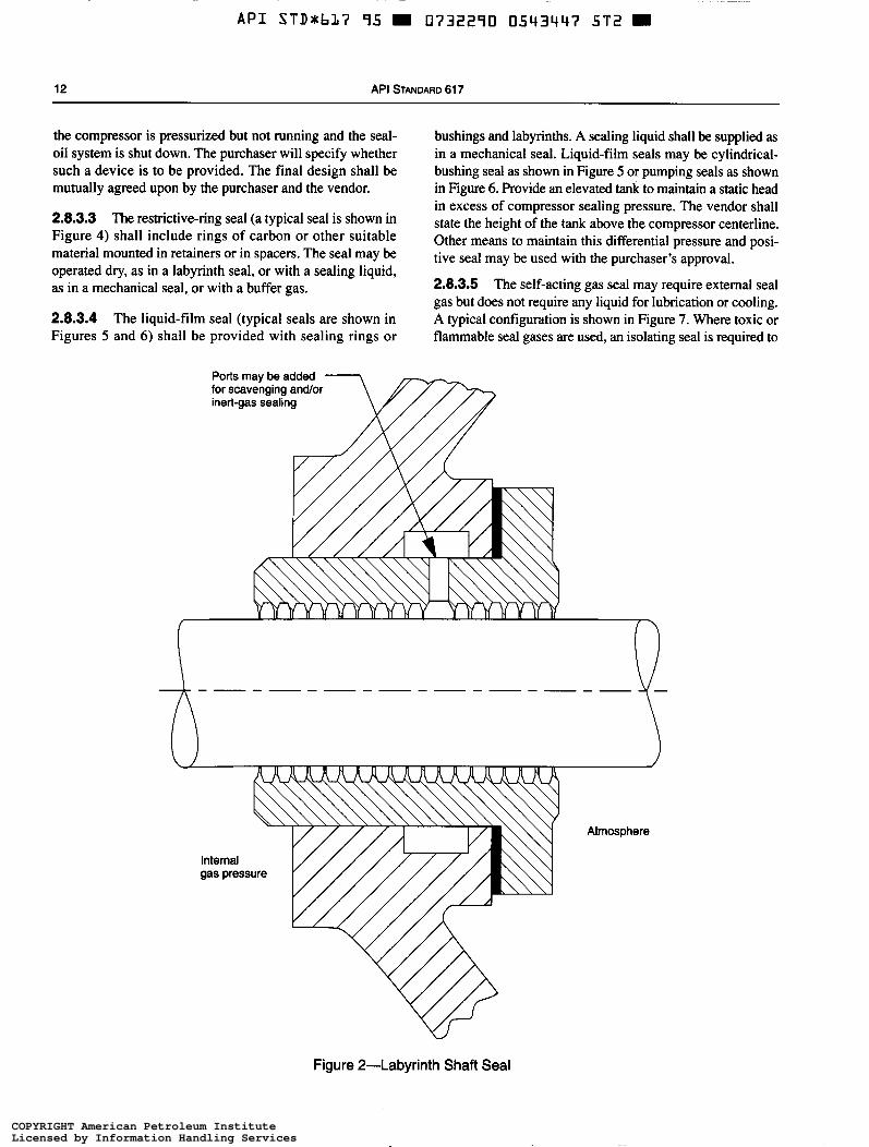
2.8.3.1 The labyrinth seal (a typical seal is shown in Figure 2) may include carbon rings in addition to the labyrinths if approved by the purchaser. Labyrinths may be stationary or rotating. Eductors or injection systems, when used, shall be furnished complete with piping, regulating and control valves, pressure gauges, and strainers. Each item shall be piped and valved to permit its removal during operation of the compressor. Where gas from the compressor discharge is used for the motivating power of the eductor, provisions must be made for sealing during startup and shutdown.
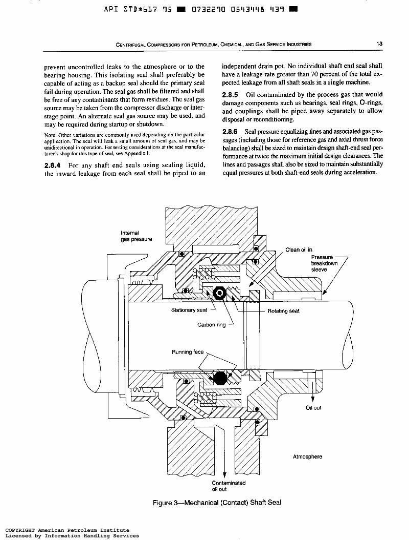
2.8.3.2 The mechanical (contact) seal (a typical seal is shown in Figure 3) shall be provided with labyrinths and slingers. Oil or other suitable liquid furnished under pressure to the rotating seal faces may be supplied from the lube-oil system or from an independent seal system. Mechanical seals shall be designed to prevent gas leaks while the com- pressor is pressurized and being shut down and after it is stopped in the event of seal-oil failure. Various supple- mental devices may be provided to ensure sealing when
COPYRIGHT American Petroleum InstituteLicensed by Information Handling ServicesCOPYRIGHT American Petroleum InstituteLicensed by Information Handling Services
A P I STDrbl7 95 0732290 0543447 5T2
12 API STANDARD 617
the compressor is pressurized but not running and the seal- oil system is shut down. The purchaser will specify whether such a device is to be provided. The final design shall be mutually agreed upon by the purchaser and the vendor.
2.8.3.3 The restrictive-ring seal (a typical seal is shown in Figure 4) shall include rings of carbon or other suitable material mounted in retainers or in spacers. The seal may be operated dry, as in a labyrinth seal, or with a sealing liquid, as in a mechanical seal, or with a buffer gas.
2.8.3.4 The liquid-film seal (typical seals are shown in Figures 5 and 6) shall be provided with sealing rings or
bushings and labyrinths. A sealing liquid shall be supplied as in a mechanical seal. Liquid-film seals may be cylindrical- bushing seal as shown in Figure 5 or pumping seals as shown in Figure 6. Provide an elevated tank to maintain a static head in excess of compressor sealing pressure. The vendor shall state the height of the tank above the compressor centerline. Other means to maintain this differential pressure and posi- tive seal may be used with the purchaser’s approval.
2.8.3.5 The self-acting gas seal may require external seal gas but does not require any liquid for lubrication or cooling. A typical configuration is shown in Figure 7. Where toxic or flammable seal gases are used, an isolating seal is required to
Ports may be added for scavenging and/or inert-gas sealing
gas pressure
Figure 2-Labyrinth Shaft Seal
COPYRIGHT American Petroleum InstituteLicensed by Information Handling ServicesCOPYRIGHT American Petroleum InstituteLicensed by Information Handling Services
A P I S T D r b L 7 95 m 0732290 0543448 439 m
CENTRIFUGAL COMPRESSORS FOR PETROLEUM, CHEMICAL, AND GAS SERVICE INDUSTRIES 13
prevent uncontrolled leaks to the atmosphere or to the bearing housing. This isolating seal shall preferably be capable of acting as a backup seal should the primary seal fail during operation. The seal gas shall be filtered and shall be free of any contaminants that form residues. The seal gas source may be taken from the compressor discharge or inter- stage point. An alternate seal gas source may be used, and may be required during startup or shutdown. Note: Other variations are commonly used depending on the particular application. The seal will leak a small amount of seal gas, and may be unidirectional in operation. For testing considerations at the seal manufac- turer's shop for this type of seal, see Appendix I .
2.8.4 For any shaft end seals using sealing liquid, the inward leakage from each seal shall be piped to an
independent drain pot. No individual shaft end seal shall have a leakage rate greater than 70 percent of the total ex- pected leakage from all shaft seals in a single machine.
2.8.5 Oil contaminated by the process gas that would damage components such as bearings, seal rings, O-rings, and couplings shall be piped away separately to allow disposal or reconditioning.
2.8.6 Seal pressure equalizing lines and associated gas pas- sages (including those for reference gas and axial thrust force balancing) shall be sized to maintain design shaft-end seal per- formance at twice the maximum initial design clearances. The lines and passages shall also be sized to maintain substantially equal pressures at both shaft-end seals during acceleration.
gas pressure
\ 1' Stationary seat
Carbon ring
Rotating seat t
Atmosphere
Contaminated oil out
Figure &Mechanical (Contact) Shaft Seal
COPYRIGHT American Petroleum InstituteLicensed by Information Handling ServicesCOPYRIGHT American Petroleum InstituteLicensed by Information Handling Services
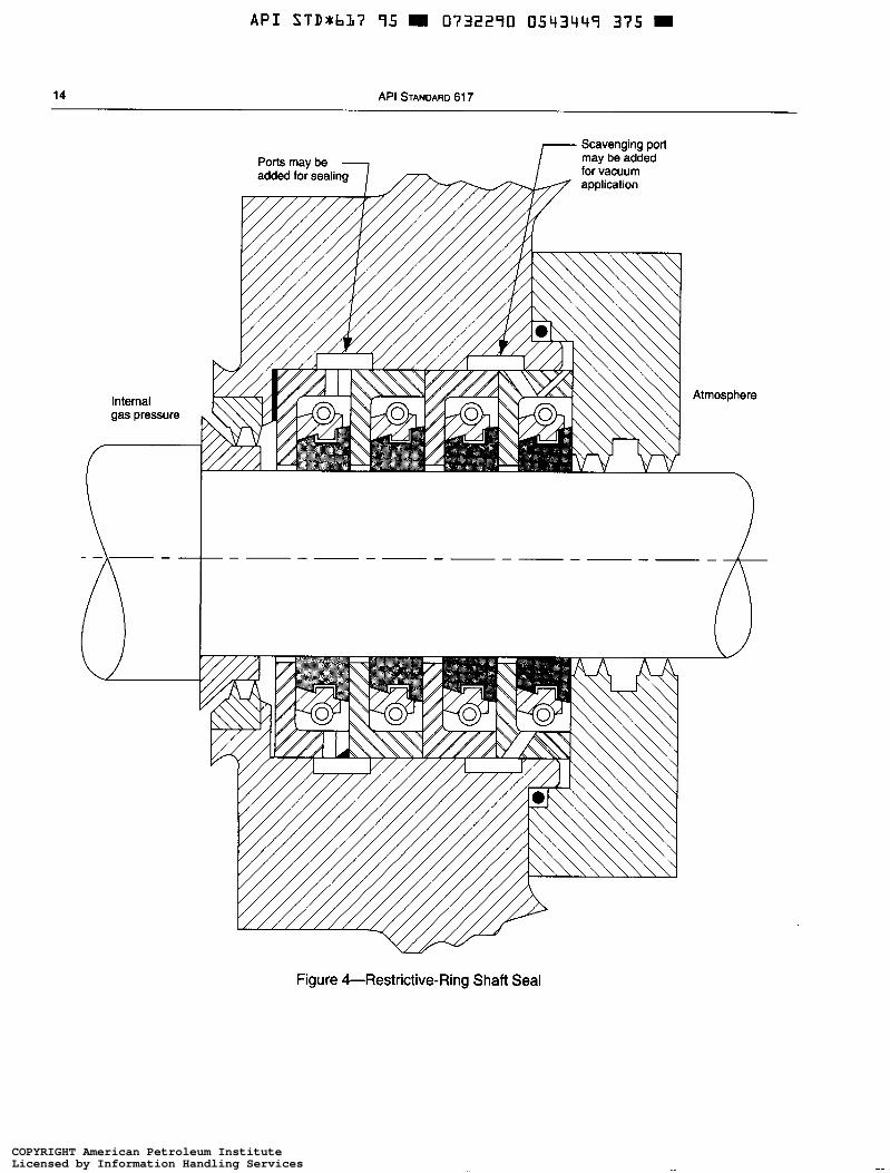
~~ ~
A P I STD+bL7 95 O732290 0543449 375 =
14 API STANDARD 617
COPYRIGHT American Petroleum InstituteLicensed by Information Handling ServicesCOPYRIGHT American Petroleum InstituteLicensed by Information Handling Services
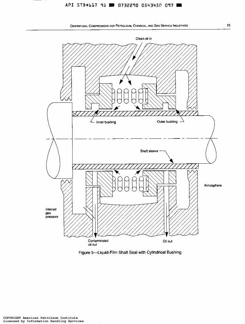
~
A P I STD*bL7 95 H 0732290 05Y3951, 097
CENTRIFUGAL COMPRESSORS FOR PETROLEUM, CHEMICAL, AND GAS SERVICE INDUSTRIES 15
Clean oil in
Contaminated oil out
Oil out
Figure 5-Liquid-Film Shaft Seal with Cylindrical Bushing
COPYRIGHT American Petroleum InstituteLicensed by Information Handling ServicesCOPYRIGHT American Petroleum InstituteLicensed by Information Handling Services
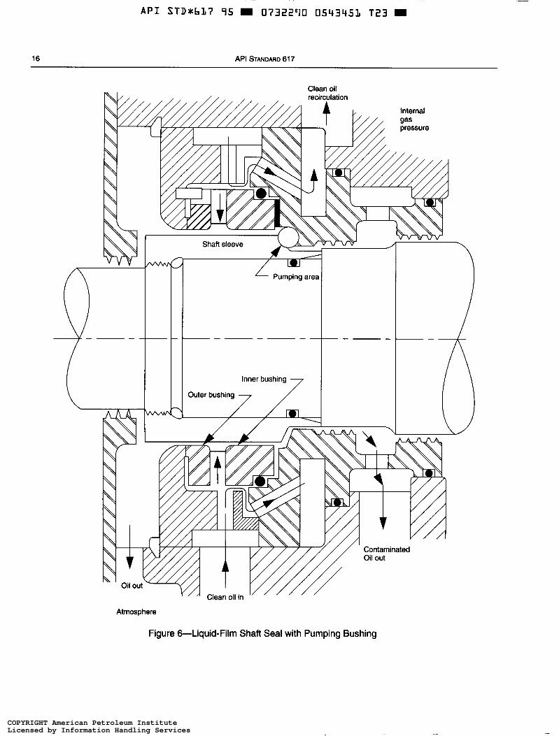
A P I STDxbL7 95 m 07322'10 0543451 T23
16 API STANDARD 617
. . Shaft sleeve
Pumping a
Inner bushing
Outer bushing
Contaminated Oil out
Atmosphere
Figure 6-Liquid-Film Shaft Seal with Pumping Bushing
COPYRIGHT American Petroleum InstituteLicensed by Information Handling ServicesCOPYRIGHT American Petroleum InstituteLicensed by Information Handling Services
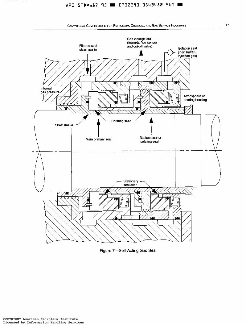
A P I STDxbL7 95 0732290 0543452 9bT
CENTRIFUGAL COMPRESSORS FOR PETROLEUM, CHEMICAL, AND GAS SERVICE INDUSTRIES 17
Internal E Filtered seal- clean gas in
I
Gas leakage out (towards flow sensor and cut-off valve)
Isolation seal (inert buffer- 4 injection gas)
I Main primary seal Backup seal or
isolating seal
Figure 7-Self-Acting Gas Seal
COPYRIGHT American Petroleum InstituteLicensed by Information Handling ServicesCOPYRIGHT American Petroleum InstituteLicensed by Information Handling Services
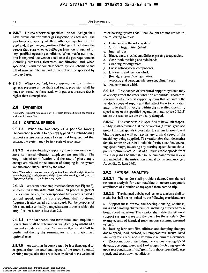
API STD*bL7 95 0732290 0543453 8Tb
O
O
18 API STANDARD 61 7
2.8.7 Unless otherwise specified, the seal design shall have provisions for buffer gas injection to each seal. The purchaser will specify whether buffer gas injection is to be used and, if so, the composition of that gas. In addition, the vendor shall state whether buffer gas injection is required for any specified operating conditions. When buffer gas injec- tion is required, the vendor shall state the gas requirements including pressures, flowrates, and filtration, and, when specified, furnish the complete control system schematic and bill of material. The method of control will be specified by the purchaser.
2.8.8 When specified, for compressors with sub atmo- spheric pressure at the shaft end seals, provision shall be made to pressurize these seals with gas at a pressure that is higher than atmospheric.
2.9 Dynamics Note: API Technical hblication 684 (TP 684) presents tutorial background pertinent to this section.
2.9.1 CRITICAL SPEEDS
2.9.1.1 When the frequency of a periodic forcing phenomenon (exciting frequency) applied to a rotor-bearing support system corresponds to a natural frequency of that system, the system may be in a state of resonance.
2.9.1.2 A rotor-bearing support system in resonance will have its normal vibration displacement amplified. The magnitude of amplification and the rate of phase-angle change are related to the amount of damping in the system and the mode shape taken by the rotor. Note: The mode shapes are commonly referred to as the first rigid (transla- tory or bouncing) mode, the second rigid (conical or rocking) mode, and the (first, second, third, ..., nth) bending mode.
2.9.1.3 When the rotor amplification factor (see Figure 8), as measured at the shaft radial vibration probes, is greater than or equal to 2.5, the corresponding frequency is called a critical speed, and the corresponding shaft rotational frequency is also called a critical speed. For the purposes of this standard, a critically damped system is one in which the amplification factor is less than 2.5.
2.9.1.4 Critical speeds and their associated amplifica- tion factors shall be determined analytically by means of a damped unbalanced rotor response analysis and shall be confirmed during the running test and any specified optional tests.
2.9.1.5 An exciting frequency may be less than, equal to, or greater than the rotational speed of the rotor. Potential
rotor-bearing systems shall include, but are not limited to, the following sources:
a. b.
d. e. f. g. h.
C.
1.
j. k.
Unbalance in the rotor system. Oil-film instabilities (whirl). Internal rubs. Blade, vane, nozzle, and diffuser passing frequencies. Gear-tooth meshing and side bands. Coupling misalignment. Loose rotor-system components. Hysteretic and friction whirl. Boundary-layer flow separation. Acoustic and aerodynamic crosscoupling forces. Asynchronous whirl.
2.9.1.6 Resonances of structural support systems may adversely affect the rotor vibration amplitude. Therefore, resonances of structural support systems that are within the vendor’s scope of supply and that affect the rotor vibration amplitude shall not occur within the specified operating speed range or the specified separation margins (see 2.8.2.5) unless the resonances are critically damped.
2.9.1.7 The vendor who is specified to have unit respon- sibility shall determine that the drive-train (turbine, gear, and motor) critical speeds (rotor lateral, system torsional, and blading modes) will not excite any critical speed of the machinery being supplied. The vendor also shall determine that the entire drive train is suitable for the specified operat- ing speed range, including any starting-speed detent (hold- point) requirements. A list of all undesirable speeds from zero to trip shall be submitted to the purchaser for his review and included in the instruction manual for his guidance (see Appendix C, Item 37d).
2.9.2 LATERAL ANALYSIS
2.9.2.1 The vendor shall provide a damped unbalanced response analysis for each machine to ensure acceptable amplitudes of vibration at any speed from zero to trip.
2.9.2.2 The damped unbalanced response analysis shall in- clude, but shall not be limited to, the following considerations:
a. Support (base, frame, and bearing-housing) stiffness, mass and damping characteristics, including effects of rota- tional speed variation. The vendor shall state the assumed support system values and the basis for these values (for example, tests of identical rotor support systems, assumed values). b. Bearing lubricant-film stiffness and damping changes due to speed, load, preload, oil temperatures, accumulated assembly tolerances, and maximum to minimum clearances. c. Rotational speed, including the various starting-speed detents, operating speed and load ranges (including agreed- upon test conditions if different from those specified), trip
exciting frequencies that are to be considered in the design of speed, and coast-down conditions.
COPYRIGHT American Petroleum InstituteLicensed by Information Handling ServicesCOPYRIGHT American Petroleum InstituteLicensed by Information Handling Services
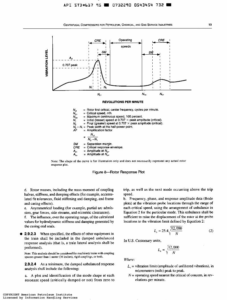
API S T D * b L ï 95 m 0732290 0543454 732 m
CENTRIFUGAL COMPRESSORS FOR PETROLEUM, CHEMICAL, AND GAS SERVICE INDUSTRIES 19
Operating - speeds
CßE L I 1
I I
I I
REVOLUTIONS PER MINUTE
= Rotor first critical, center frequency, cycles per minute. = Critical speed, nth. = Maximum continuous speed, 105 percent. = Initial (lesser) speed at 0.707 x peak amplitude (critical). = Final (greater) speed at 0.707 x peak amplitude (critical).
= Amplification factor N, = Peak width at the half-power point.
NCl N2 -4
= -
SM = Separation margin. CßE = Critical response envelope. 4, = Amplitude at Ncl. 4, = Amplitude at Ncn.
Note: The shape of the curve is for illustration only and does not necessarily represent any actual rotor response plot.
Figure &Rotor Response Plot
d. Rotor masses, including the mass moment of coupling halves, stiffness, and damping effects (for example, accumu- lated fit tolerances, fluid stiffening and damping, and frame and casing effects). e. Asymmetrical loading (for example, partial arc admis- sion, gear forces, side streams, and eccentric clearances). f. The influence, over the operating range, of the calculated values for hydrodynamic stiffness and damping generated by the casing end seals.
O 2.9.2.3 When specified, the effects of other equipment in the train shall be included in the damped unbalanced response analysis (that is, a train lateral analysis shall be performed). Note: This analysis should be considered for machinery trains with coupling spacers greater than 1 meter (36 inches), rigid couplings, or both.
2.9.2.4 As a minimum, the damped unbalanced response analysis shall include the following:
a. A plot and identification of the mode shape at each resonant speed (critically damped or not) from zero to
trip, as well as the next mode occurring above the trip speed. b. Frequency, phase, and response amplitude data (Bode plots) at the vibration probe locations through the range of each critical speed, using the arrangement of unbalance in Equation 2 for the particular mode. This unbalance shall be sufficient to raise the displacement of the rotor at the probe locations to the vibration limit defined by Equation 2:
'12,000 L, =25.4 1- I N
In U.S. Customary units,
12,000 r, = Jy Where:
L, = vibration limit (amplitude of unfiltered vibration), in
N = operating speed nearest the critical of concern, in rev- micrometers (mils) peak to peak.
olutions per minute.
COPYRIGHT American Petroleum InstituteLicensed by Information Handling ServicesCOPYRIGHT American Petroleum InstituteLicensed by Information Handling Services
_____
A P I STD*bL7 95 D 0732290 0543455 679 D
20 API STANDARD 617
This unbalance shall be no less than two times the unbalance defined by the Equation 3:
U,,, = 635OWlN (3 )
In U.S. Customary units,
U,,, = 4WlN
Where:
U = input unbalance from the rotor dynamic response analysis in gram-millimeters (ounce-inches).
W = journal static weight load, in kilograms (pounds); or for bending modes where the maximum deflection occurs at the shaft ends, the overhung weight load (that is, the weight outboard of the bearing), in kilo- grams (pounds).
N = operating speed nearest the critical of concern, in rev- olutions per minute.
The unbalance weight or weights shall be placed at the locations that have been analytically determined to affect the particular mode most adversely. For translatory modes, the unbalance shall be based on both journal static weights and shall be applied at the locations of maximum displacement. For conical modes, each unbalance shall be based on the journal weight and shall be applied at the loca- tion of maximum displacement of the mode nearest the jour- nal used for the unbalance calculation, 180 degrees out of phase. Figure 2 shows the typical mode shapes and indicates the location and definition of U for each of the shapes. c. Modal diagrams for each response in 2.9.2.4, Item b, shall indicate the phase and major-axis amplitude at each coupling engagement plane, the centerlines of the bearings, the locations of the vibration probes, and each seal area throughout the machine. The minimum design diametral running clearance of the seals shall also be indicated. d. To establish the validity of the analytical model, a veri- fication test of the rotor unbalance is required at the comple- tion of the mechanical running test. Therefore, additional plots based on the actual unbalance to be used during the test shall be provided. For machines that meet the requirements of 2.9.2.4, Item b, the location of the test unbalance shall be determined by the vendor. The amount of unbalance shall be sufficient to raise the vibration levels, as measured at the vibration probes, to those specified in 2.9.2.4, Item b. In all cases, the unbalance plots shall include the effects of any test-stand conditions (including the effects of test seals) that may be used during the verification test of the rotor unbalance (see 2.9.3). e. Unless otherwise specified, a stiffness map shall be pro- vided of the undamped rotor response from which the damped unbalanced response analysis specified in 2.9.2.4, Item c, was derived. This plot shall show frequency versus support system stiffness, with the calculated support system stiffness curves superimposed.
f. For machines whose bearing support system stiffness values are less than or equal to 3.5 times the bearing stiffness values, use either the calculated frequency-dependent sup- port stiffness and damping values (impedances) or the values derived from modal testing. The results of the damped unbalanced response analysis shall include Bode plots that compare absolute shaft motion with shaft motion relative to the bearing housing.
2.9.2.5 The damped unbalance response analysis shall indicate that the machine in the unbalanced condition described in 2.9.2.4, Item b, will meet the following accep- tance criteria (see Figure 8):
a. If the amplification factor is less than 2.5, the response is considered critically damped and no separation margin is required. b. If the amplification factor is 2.5 to 3.55, a separation mar- gin of 15 percent above the maximum continuous speed and 5 percent below the minimum operating speed is required. c. If the amplification factor is greater than 3.55 and the critical response peak is below the minimum operating speed, the required separation margin (a percentage of minimum speed) is equal to the following:
6 SM=lOO- 84+- ( A F - 3 ) (4)
Where:
SM = Separation margin. AF = Amplification factor.
d. If the amplification factor is greater than 3.55 and the critical response peak is above the trip speed, the required separation margin (a percentage of maximum continuous speed) is equal to the following:
Where:
SM = Separation margin. AF = Amplification factor.
2.9.2.6 The calculated unbalanced peak-to-peak rotor amplitudes (see 2.9.2.4, Item b) at any speed from zero to trip shall not exceed 75 percent of the minimum design diametral running clearances throughout the machine (with the exception of floating-ring seal locations).
2.9.2.7 If, after the purchaser and the vendor have agreed that all practical design efforts have been exhausted, the analysis indicates that the separation margins still cannot be met or that a critical response peak falls within the operating speed range, acceptable amplitudes shall be mutually agreed upon by the purchaser and the vendor, subject to the require- ments of 2.9.2.6.
COPYRIGHT American Petroleum InstituteLicensed by Information Handling ServicesCOPYRIGHT American Petroleum InstituteLicensed by Information Handling Services
A P I STD*hL7 95 m 0732290 0543456 505 m
CENTRIFUGAL COMPRESSORS FOR PETROLEUM, CHEMICAL, AND GAS SERVICE INDUSTRIES 21
2.9.3 SHOP VERIFICATION OF UNBALANCED RESPONSE ANALYSIS
2.9.3.1 A demonstration of rotor response at future unbal- anced conditions is necessary because a well-balanced rotor may not be representative of future operating conditions (see 2.9.2.4, Item d). This test shall be performed as part of the mechanical running test (see 4.3.3) and the results shall be used to verify the analytical model. Unless otherwise specified, the verification test of the rotor unbalance shall be performed only on the first rotor (normally the spare rotor, if two rotors are purchased). The actual response of the rotor on the test stand to the same unbalance weight as was used to develop the Bode plots specified in 2.9.2.4 shall be the crite- rion for determining the validity of the damped unbalanced response analysis. To accomplish this, the following proce- dure shall be followed:
a. During the mechanical running test (see 4.3.4), the amplitudes and phase angle of the indicated vibration at the speed nearest the critical or criticals of concern shall be determined. b. A trial weight, not more than one-half the Amount calcu- lated in 2.9.2.4, Item b, shall be added to the rotor at the location specified in 2.9.2.4, Item d; 90 degrees away from the phase of the indicated vibration at the speed or speeds closest to the critical or criticals of concern. c. The machine shall then be brought up to the operating speed nearest the critical of concern, and the indicated vibra- tion amplitudes and phase shall be measured. The results of this test and the corresponding indicated vibration data from 2.9.3.1, Item a, shall be vectorially added to determine the magnitude and phase location of the final test weight required to produce the required test vibration amplitudes. d. The final test weight described in 2.9.3.1, Item c, shall be added to the rotor and the machine shall be brought up to the operating speed nearest the critical of concern. When more than one critical of concern exists, additional test runs shall be performed for each, using the highest speed for the initial test run. Note: The dynamic response of the machine on the test stand will be a func- tion of the agreed-upon test conditions and, unless the test-stand results are obtained at the conditions of pressure, temperature, speed, and load expected in the field, they may not be the same as the results expected in the field.
2.9.3.2 The parameters to be measured during the test shall be speed and shaft synchronous (1 X) vibration ampli- tudes with corresponding phase. The vibration amplitudes and phase from each pair of x-y vibration probes shall be vectorially summed at each response peak to determine the maximum amplitude of vibration. The major-axis amplitude of each response peak shall not exceed the limits specified in 2.9.2.6. (More than one application of the unbalance weight and test run may be required to satisfy these criteria.)
The gain of the recording instruments used shall be pre- determined and preset before the test so that the highest
response peak is within 6Cb100 percent of the recorder’s full scale on the test-unit coast-down (deceleration). The major- axis amplitudes at the operating speed nearest the critical or criticals of concern shall not exceed the values predicted in accordance with 2.9.2.4, Item d, before coastdown through the critical of concem.
2.9.3.2.1 Vectorial addition of slow-roll(3004ûû revolu- tions per minute) electrical and mechanical runout is required to determine the actual vibration amplitudes and phase during the verification tests. Vectorial addition of the bearing-housing motion is required for machines that have flexible rotor sup- ports (see 2.9.2.4, Item f). Note 1 : The phase on each vibration signal, x or y, is the angular measure, in degrees, of the phase difference (lag) between a phase reference signal (from a phase transducer sensing a once-per-revolution mark on the rotor, as described in API Standard 670) and the next positive peak, in time, of the synchronous ( I X) vibration signal. (A phase change will occur through a critical or if a change in a rotor’s balance condition occurs because of shift- ing or looseness in the assembly.)
Note 2: The major-axis amplitude is properly determined from a lissajous (orbit) display on an oscilloscope, or equivalent instrument. When the phase angle between the x and y signals is not 90 degrees, the major axis ampli- tude can be approximated by (x‘ + y*)”’. When the phase angle between the x and y signals is 90 degrees, the major-axis value is the greater of the two vibration signals.
2.9.3.2.2 The results of the verification test shall be com- pared with those from the original analytical model. The vendor shall correct the model if it fails to meet any of the following criteria:
a. The actual critical speeds shall not deviate from the pre- dicted speeds by more than f5 percent. b. The predicted amplification factors shall not deviate from the actual test-stand values by more than I20 percent. c. The actual response peak amplitudes, including those that are critically damped, shall be within I50 percent of the predicted amplitudes.
2.9.3.3 Additional testing is required if, from the test data described or from the damped, corrected unbalanced response analysis (see 2.9.3.2.2), it appears that either of the following conditions exists:
a. Any critical response will fail to meet the separation margin requirements (see 2.9.2.5) or will fall within the operating speed range. b. The requirements of 2.9.2.6 have not been met.
2.9.3.4 Rotors requiring additional testing per 2.9.3.3 shall receive additional testing as follows: Unbalance weights shall be placed as described in 2.9.2.4, Item b; this may require disassembly of the machine. Unbalance magni- tudes shall be achieved by adjusting the indicated unbalance that exists in the rotor from the initial run to raise the dis- placement of the rotor at the probe locations to the vibration limit defined by Equation 2 (see 2.9.2.4, Item b) at the maximum continuous speed. However, the unbalance used
COPYRIGHT American Petroleum InstituteLicensed by Information Handling ServicesCOPYRIGHT American Petroleum InstituteLicensed by Information Handling Services
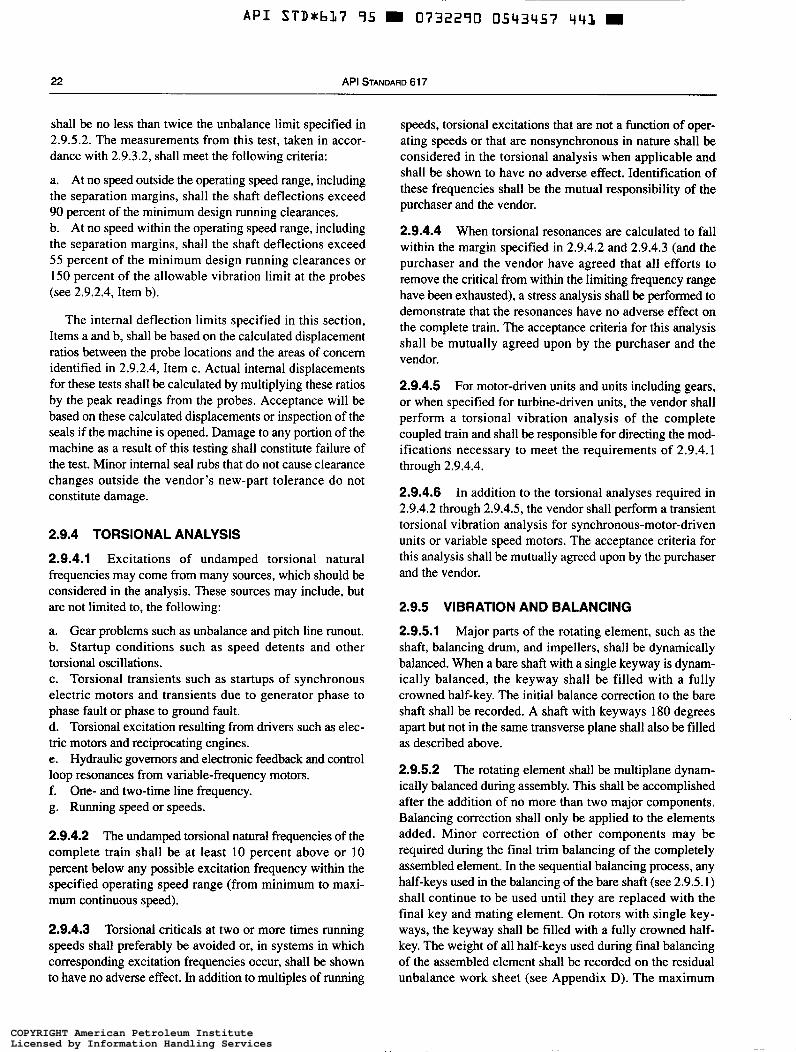
A P I STDxbL7 95 9
22 API STANDA
shall be no less than twice the iinbalance limit specified in 2.9.5.2. The measurements from this test, taken in accor- dance with 2.9.3.2, shall meet the following criteria:
a. At no speed outside the operating speed range, including the separation margins, shall the shaft deflections exceed 90 percent of the minimum design running clearances. b. At no speed within the operating speed range, including the separation margins, shall the shaft deflections exceed 55 percent of the minimum design running clearances or i 50 percent of the allowable vibration limit at the probes (see 2.9.2.4, Item b).
The internal deflection limits specified in this section, Items a and b, shall be based on the calculated displacement ratios between the probe locations and the areas of concern identified in 2.9.2.4, Item c. Actual internal displacements for these tests shall be calculated by multiplying these ratios by the peak readings from the probes. Acceptance will be based on these calculated displacements or inspection of the seals if the machine is opened. Damage to any portion of the machine as a result of this testing shall constitute failure of the test. Minor internal seal rubs that do not cause clearance changes outside the vendor’s new-part tolerance do not constitute damage.
2.9.4 TORSIONAL ANALYSIS
2.9.4.1 Excitations of undamped torsional natural frequencies may come from many sources, which should be considered in the analysis. These sources may include, but are not limited to, the following:
a. Gear problems such as unbalance and pitch line runout. b. Startup conditions such as speed detents and other torsional oscillations. c. Torsional transients such as startups of synchronous electric motors and transients due to generator phase to phase fault or phase to ground fault. d. Torsional excitation resulting from drivers such as elec- tric motors and reciprocating engines. e. Hydraulic governors and electronic feedback and control loop resonances from variable-frequency motors. f. One- and two-time line frequency. g. Running speed or speeds.
2.9.4.2 The undamped torsional natural frequencies of the complete train shall be at least 10 percent above or 10 percent below any possible excitation frequency within the specified operating speed range (from minimum to maxi- mum continuous speed).
2.9.4.3 Torsional criticals at two or more times running speeds shall preferably be avoided or, in systems in which corresponding excitation frequencies occur, shall be shown to have no adverse effect. In addition to multiples of running
0732290 0543457
RD 617
441 9
speeds, torsional excitations that are not a function of oper- ating speeds or that are nonsynchronous in nature shall be considered in the torsional analysis when applicable and shall be shown to have no adverse effect. Identification of these frequencies shall be the mutual responsibility of the purchaser and the vendor.
2.9.4.4 When torsional resonances are calculated to fall within the margin specified in 2.9.4.2 and 2.9.4.3 (and the purchaser and the vendor have agreed that all efforts to remove the critical from within the limiting frequency range have been exhausted), a stress analysis shall be performed to demonstrate that the resonances have no adverse effect on the complete train. The acceptance criteria for this analysis shall be mutually agreed upon by the purchaser and the vendor.
2.9.4.5 For motor-driven units and units including gears, or when specified for turbine-driven units, the vendor shall perform a torsional vibration analysis of the complete coupled train and shall be responsible for directing the mod- ifications necessary to meet the requirements of 2.9.4.1 through 2.9.4.4.
2.9.4.6 In addition to the torsional analyses required in 2.9.4.2 through 2.9.4.5, the vendor shall perform a transient torsional vibration analysis for synchronous-motor-driven units or variable speed motors. The acceptance criteria for this analysis shall be mutually agreed upon by the purchaser and the vendor.
2.9.5 VIBRATION AND BALANCING
2.9.5.1 Major parts of the rotating element, such as the shaft, balancing drum, and impellers, shall be dynamically balanced. When a bare shaft with a single keyway is dynam- ically balanced, the keyway shall be filled with a fully crowned half-key. The initial balance correction to the bare shaft shall be recorded. A shaft with keyways 180 degrees apart but not in the same transverse plane shall also be filled as described above.
2.9.5.2 The rotating element shall be multiplane dynam- ically balanced during assembly. This shall be accomplished after the addition of no more than two major components. Balancing correction shall only be applied to the elements added. Minor correction of other components may be required during the final trim balancing of the completely assembled element. In the sequential balancing process, any half-keys used in the balancing of the bare shaft (see 2.9.5.1) shall continue to be used until they are replaced with the final key and mating element. On rotors with single key- ways, the keyway shall be filled with a fully crowned half- key. The weight of all half-keys used during final balancing of the assembled element shall be recorded on the residual unbalance work sheet (see Appendix D). The maximum
COPYRIGHT American Petroleum InstituteLicensed by Information Handling ServicesCOPYRIGHT American Petroleum InstituteLicensed by Information Handling Services
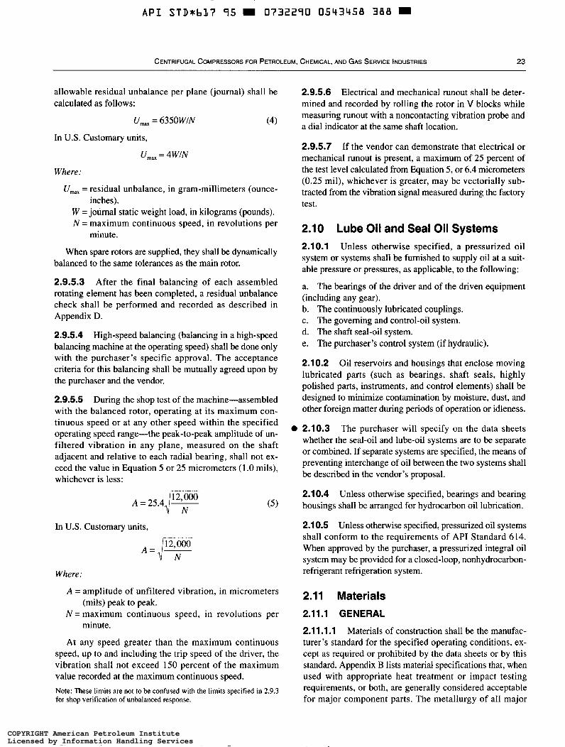
~~~ ~ ~
A P I STD*bL7 95 rn 0732290 0543458 388 rn
CENTRIFUGAL COMPRESSORS FOR PETROLEUM, CHEMICAL, AND GAS SERVICE INDUSTRIES 23
allowable residual unbalance per plane (journal) shall be calculated as follows:
U,,, = 6350WtN (4 )
In U.S. Customary units,
U,,, = 4WfN
Where.
U,,,,, = residual unbalance, in gram-millimeters (ounce-
W =journal static weight load, in kilograms (pounds). N = maximum continuous speed, in revolutions per
inches).
minute.
When spare rotors are supplied, they shall be dynamically balanced to the same tolerances as the main rotor.
2.9.5.3 After the final balancing of each assembled rotating element has been completed, a residual unbalance check shall be performed and recorded as described in Appendix D.
2.9.5.4 High-speed balancing (balancing in a high-speed balancing machine at the operating speed) shall be done only with the purchaser's specific approval. The acceptance criteria for this balancing shall be mutually agreed upon by the purchaser and the vendor.
2.9.5.5 During the shop test of the machine-assembled with the balanced rotor, operating at its maximum con- tinuous speed or at any other speed within the specified operating speed range-the peak-to-peak amplitude of un- filtered vibration in any plane, measured on the shaft adjacent and relative to each radial bearing, shall not ex- ceed the value in Equation 5 or 25 micrometers ( 1 .O mils), whichever is less:
In U.S. Customary units,
A = ,I";N" Where:
( 5 )
A = amplitude of unfiltered vibration, in micrometers
N = maximum continuous speed, in revolutions per
At any speed greater than the maximum continuous speed, up to and including the trip speed of the driver, the vibration shall not exceed 150 percent of the maximum value recorded at the maximum continuous speed. Note: These limits are not to be confused with the limits specified in 2.9.3 for shop verification of unbalanced response.
(mils) peak to peak.
minute.
O
2.9.5.6 Electrical and mechanical runout shall be deter- mined and recorded by rolling the rotor in V blocks while measuring runout with a noncontacting vibration probe and a dial indicator at the same shaft location.
2.9.5.7 If the vendor can demonstrate that electrical or mechanical runout is present, a maximum of 25 percent of the test level calculated from Equation 5, or 6.4 micrometers (0.25 mil), whichever is greater, may be vectorially sub- tracted from the vibration signal measured during the factory test.
2.10 Lube Oil and Seal Oil Systems 2.1 0.1 Unless otherwise specified, a pressurized oil system or systems shall be furnished to supply oil at a suit- able pressure or pressures, as applicable, to the following:
a. The bearings of the driver and of the driven equipment (including any gear). b. The continuously lubricated couplings. c. The governing and control-oil system. d. The shaft seal-oil system. e. The purchaser's control system (if hydraulic).
2.10.2 Oil reservoirs and housings that enclose moving lubricated parts (such as bearings, shaft seals, highly polished parts, instruments, and control elements) shall be designed to minimize contamination by moisture, dust, and other foreign matter during periods of operation or idleness.
2.10.3 The purchaser will specify on the data sheets whether the seal-oil and lube-oil systems are to be separate or combined. If separate systems are specified, the means of preventing interchange of oil between the two systems shall be described in the vendor's proposal.
2.1 0.4 Unless otherwise specified, bearings and bearing housings shall be arranged for hydrocarbon oil lubrication.
2.1 0.5 Unless otherwise specified, pressurized oil systems shall conform to the requirements of APT Standard 614. When approved by the purchaser, a pressurized integral oil system may be provided for a closed-loop, nonhydrocarbon- refrigerant refrigeration system.
2.11 Materials 2.11.1 GENERAL
2.11.1.1 Materials of construction shall be the manufac- turer's standard for the specified operating conditions, ex- cept as required or prohibited by the data sheets or by this standard. Appendix B lists material specifications that, when used with appropriate heat treatment or impact testing requirements, or both, are generally considered acceptable for major component parts. The metallurgy of all major
COPYRIGHT American Petroleum InstituteLicensed by Information Handling ServicesCOPYRIGHT American Petroleum InstituteLicensed by Information Handling Services
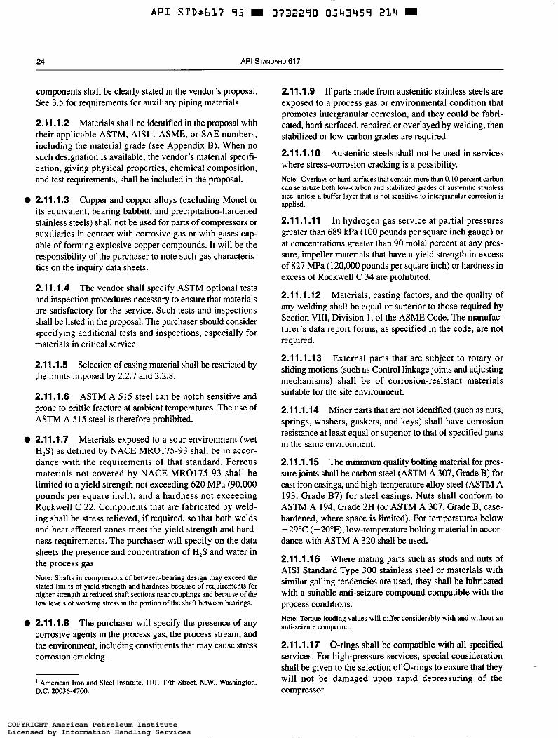
API STDab17 95 H O732290 0543459 2/11
24 API S TANDARD 61 7
components shall be clearly stated in the vendor's proposal. See 3.5 for requirements for auxiliary piping materials.
2.11.1.2 Materials shall be identified in the proposal with their applicable ASTM, AISI': ASME, or SAE numbers, including the material grade (see Appendix B). When no such designation is available, the vendor's material specifi- cation, giving physical properties, chemical composition, and test requirements, shall be included in the proposal.
2.11.1.3 Copper and copper alloys (excluding Monel or its equivalent, bearing babbitt, and precipitation-hardened stainless steels) shall not be used for parts of compressors or auxiliaries in contact with corrosive gas or with gases cap- able of forming explosive copper compounds. It will be the responsibility of the purchaser to note such gas characteris- tics on the inquiry data sheets.
2.11.1.4 The vendor shall specify ASTM optional tests and inspection procedures necessary to ensure that materials are satisfactory for the service. Such tests and inspections shall be listed in the proposal. The purchaser should consider specifying additional tests and inspections, especially for materials in critical service.
2.11.1.5 the limits imposed by 2.2.7 and 2.2.8.
Selection of casing material shall be restricted by
2.11.1.6 ASTM A 515 steel can be notch sensitive and prone to brittle fracture at ambient temperatures. The use of ASTM A 5 15 steel is therefore prohibited.
2.1 1 .1.7 Materials exposed to a sour environment (wet HIS) as defined by NACE MRO175-93 shall be in accor- dance with the requirements of that standard. Ferrous materials not covered by NACE MR017.5-93 shall be limited to a yield strength not exceeding 620 MPa (90,000 pounds per square inch), and a hardness not exceeding Rockwell C 22. Components that are fabricated by weld- ing shall be stress relieved, if required, so that both welds and heat affected zones meet the yield strength and hard- ness requirements. The purchaser will specify on the data sheets the presence and concentration of H,S and water in the process gas. Note: Shafts in compressors of between-bearing design may exceed the stated limits of yield strength and hardness because of requirements for higher strength at reduced shaft sections near couplings and because of the low levels of working stress in the portion of the shaft between bearings.
2.11.1.8 The purchaser will specify the presence of any corrosive agents in the process gas, the process stream, and the environment, including constituents that may cause stress corrosion cracking.
"American Iron and Steel Institute, 1101 17th Street, N.W., Washington, D.C. 20036-4700.
2.11.1.9 If parts made from austenitic stainless steels are exposed to a process gas or environmental condition that promotes intergranular corrosion, and they could be fabri- cated, hard-surfaced, repaired or overlayed by welding, then stabilized or low-carbon grades are required.
2.1 1.1.10 Austenitic steels shall not be used in services where stress-corrosion cracking is a possibility. Note: Overlays or hard surfaces that contain more than O. IO percent carbon can sensitize both low-carbon and stabilized grades of austenitic stainless steel unless a buffer layer that is not sensitive to intergranular corrosion is applied.
2.11.1 .ll In hydrogen gas service at partial pressures greater than 689 kPa (100 pounds per square inch gauge) or at concentrations greater than 90 molal percent at any pres- sure, impeller materials that have a yield strength in excess of 827 MPa (120,000 pounds per square inch) or hardness in excess of Rockwell C 34 are prohibited.
2.11.1.12 Materials, casting factors, and the quality of any welding shall be equal or superior to those required by Section VIII, Division 1, of the ASME Code. The manufac- turer's data report forms, as specified in the code, are not required.
2.11.1.13 External parts that are subject to rotary or sliding motions (such as Control linkage joints and adjusting mechanisms) shall be of corrosion-resistant materials suitable for the site environment.
2.11.1.14 Minor parts that are not identified (such as nuts, springs, washers, gaskets, and keys) shall have corrosion resistance at least equal or superior to that of specified parts in the same environment.
2.11.1.15 The minimum quality bolting material for pres- sure joints shall be carbon steel (ASTM A 307, Grade B) for cast iron casings, and high-temperature alloy steel (ASTM A 193, Grade B7) for steel casings. Nuts shall conform to ASTM A 194, Grade 2H (or ASTM A 307, Grade B, case- hardened, where space is limited). For temperatures below -29°C ( -20°F), low-temperature bolting material in accor- dance with ASTM A 320 shall be used.
2.11.1.16 Where mating parts such as studs and nuts of AIS1 Standard Type 300 stainless steel or materials with similar galling tendencies are used, they shall be lubricated with a suitable anti-seizure compound compatible with the process conditions. Note: Torque loading values will differ considerably with and without an anti-seizure compound.
2.11.1.17 O-rings shall be compatible with all specified services. For high-pressure services, special consideration shall be given to the selection of O-rings to ensure that they will not be damaged upon rapid depressuring of the compressor.
-
COPYRIGHT American Petroleum InstituteLicensed by Information Handling ServicesCOPYRIGHT American Petroleum InstituteLicensed by Information Handling Services
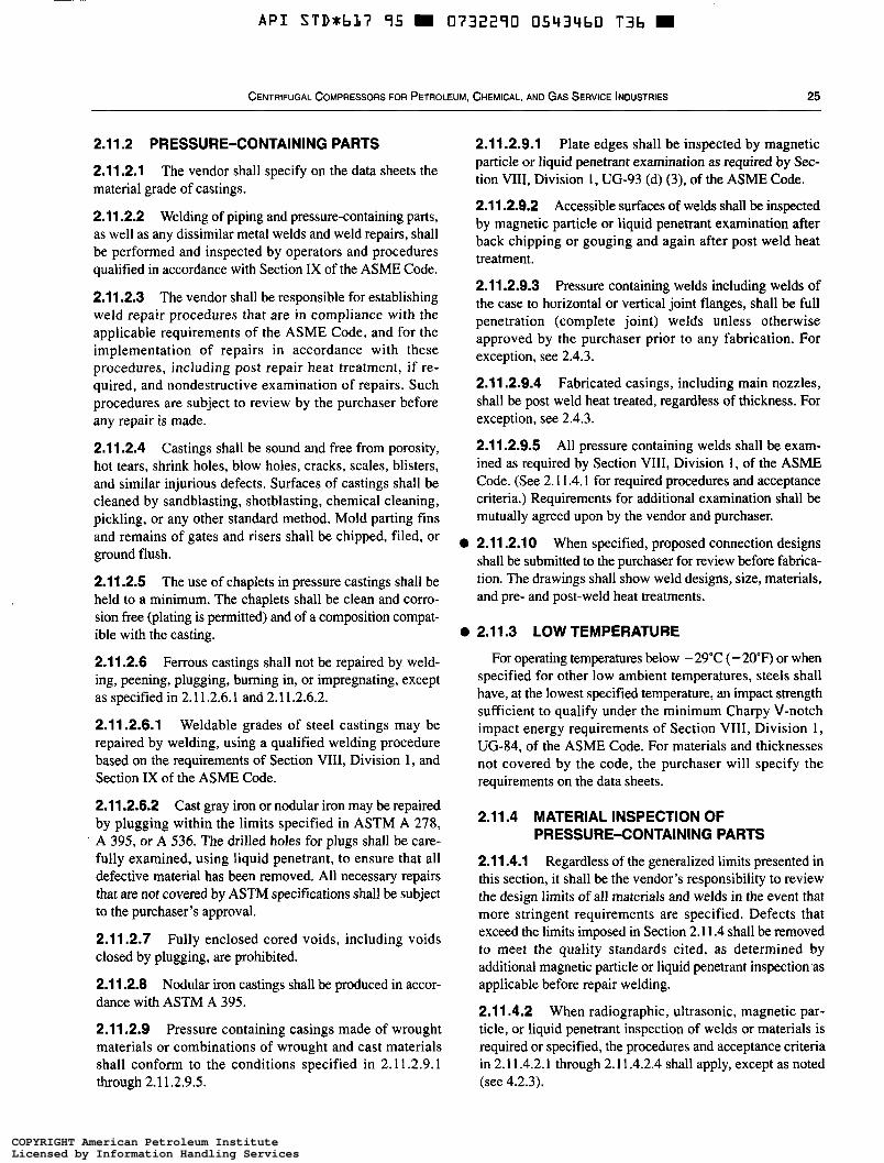
A P I STD*bLi 95 0732290 0543460 T3b
CENTRIFUGAL COMPRESSORS FOR PETROLEUM, CHEMICAL, AND GAS SERVICE INDUSTRIES 25
2.11.2 PRESSURE-CONTAINING PARTS
2.11.2.1 The vendor shall specify on the data sheets the material grade of castings.
2.1 1.2.2 Welding of piping and pressure-containing parts, as well as any dissimilar metal welds and weld repairs, shall be performed and inspected by operators and procedures qualified in accordance with Section IX of the ASME Code.
2.11.2.3 The vendor shall be responsible for establishing weld repair procedures that are in compliance with the applicable requirements of the ASME Code, and for the implementation of repairs in accordance with these procedures, including post repair heat treatment, if re- quired, and nondestructive examination of repairs. Such procedures are subject to review by the purchaser before any repair is made.
2.11.2.4 Castings shall be sound and free from porosity, hot tears, shrink holes, blow holes, cracks, scales, blisters, and similar injurious defects. Surfaces of castings shall be cleaned by sandblasting, shotblasting, chemical cleaning, pickling, or any other standard method. Mold parting fins and remains of gates and risers shall be chipped, filed, or ground flush.
2.11.2.5 The use of chaplets in pressure castings shall be held to a minimum. The chaplets shall be clean and corro- sion free (plating is permitted) and of a composition compat- ible with the casting.
2.11.2.6 Ferrous castings shall not be repaired by weld- ing, peening, plugging, burning in, or impregnating, except as specified in 2.1 1.2.6.1 and 2.11.2.6.2.
2.11.2.6.1 Weldable grades of steel castings may be repaired by welding, using a qualified welding procedure based on the requirements of Section VIII, Division 1, and Section IX of the ASME Code.
2.11.2.6.2 Cast gray iron or nodular iron may be repaired by plugging within the limits specified in ASTM A 278, A 395, or A 536. The drilled holes for plugs shall be care- fully examined, using liquid penetrant, to ensure that all defective material has been removed. All necessary repairs that are not covered by ASTM specifications shall be subject to the purchaser’s approval.
2.11.2.7 Fully enclosed cored voids, including voids closed by plugging, are prohibited.
2.1 1.2.8 Nodular iron castings shall be produced in accor- dance with ASTM A 395.
2.11.2.9 Pressure containing casings made of wrought materials or combinations of wrought and cast materials shall conform to the conditions specified in 2.11.2.9.1 through 2.1 1.2.9.5.
2.11.2.9.1 Plate edges shall be inspected by magnetic particle or liquid penetrant examination as required by Sec- tion VIU, Division 1, UG-93 (d) (3), of the ASME Code.
2.11.2.9.2 Accessible surfaces of welds shall be inspected by magnetic particle or liquid penetrant examination after back chipping or gouging and again after post weld heat treatment.
2.1 1.2.9.3 Pressure containing welds including welds of the case to horizontal or vertical joint flanges, shall be full penetration (complete joint) welds unless otherwise approved by the purchaser prior to any fabrication. For exception, see 2.4.3.
2.1 1.2.9.4 Fabricated casings, including main nozzles, shall be post weld heat treated, regardless of thickness. For exception, see 2.4.3.
2.11.2.9.5 All pressure containing welds shall be exam- ined as required by Section VIII, Division 1 , of the ASME Code. (See 2. I 1.4.1 for required procedures and acceptance criteria.) Requirements for additional examination shall be mutually agreed upon by the vendor and purchaser.
2.11.2.1 O When specified, proposed connection designs shall be submitted to the purchaser for review before fabrica- tion. The drawings shall show weld designs, size, materials, and pre- and post-weld heat treatments.
2.11.3 LOW TEMPERATURE
For operating temperatures below - 29°C ( - 20’F) or when specified for other low ambient temperatures, steels shall have, at the lowest specified temperature, an impact strength sufficient to qualify under the minimum Charpy V-notch impact energy requirements of Section VIII, Division 1, UG-84, of the ASME Code. For materials and thicknesses not covered by the code, the purchaser will specify the requirements on the data sheets.
2.11.4 MATERIAL INSPECTION OF PRESSURE-CONTAINING PARTS
2.1 1.4.1 Regardless of the generalized limits presented in this section, it shall be the vendor’s responsibility to review the design limits of all materials and welds in the event that more stringent requirements are specified. Defects that exceed the limits imposed in Section 2.1 1.4 shall be removed to meet the quality standards cited, as determined by additional magnetic particle or liquid penetrant inspection.as applicable before repair welding.
2.1 1.4.2 When radiographic, ultrasonic, magnetic par- ticle, or liquid penetrant inspection of welds or materials is required or specified, the procedures and acceptance criteria in 2.11.4.2.1 through 2.1 1.4.2.4 shall apply, except as noted (see 4.2.3).
COPYRIGHT American Petroleum InstituteLicensed by Information Handling ServicesCOPYRIGHT American Petroleum InstituteLicensed by Information Handling Services
~~~
A P I STDabl7 95 0732290 05q34bL 972
26 API STANDARD 61 7
2.1 1.4.2.1 Radiographic examination shall be in accor- dance with Section VIII, Division 1, UW-51 (100 percent) and UW-52 (spot), of the ASME Code. Spot radiography shall consist of a minimum of one 150-millimeter (6-inch) spot radiograph for each 7.6 meters (25 feet) of weld on each casing. As a minimum, one spot radiograph is required for each welding procedure and welder used for pressure- containing welds.
2.11.4.2.2 Ultrasonic examination shall be in accordance with Section VIII, Division 1, UW 53 and Appendix 12 of the ASME Code.
2.11.4.2.3 Magnetic particle examination shall be in accordance with Section VIII, Division 1, Appendix 6, of the ASME Code and ASTM A 709. Linear indications shall be considered relevant only if the major dimension exceeds 1.6 millimeters ('/I6 inch). Individual indications that are sepa- rated by less than l .6 millimeters ('/16 inch) shall be con- sidered continuous.
2.11.4.2.4 Liquid penetrant examination shall be in accor- dance with Section VIII, Division I , Appendix 8, of the ASME Code.
2.1 1.4.3 Cast steel casing parts shall be examined by magnetic particle methods. Acceptability of defects shall be based on a comparison with the photographs in ASTM E 125. For each type of defect, the degree of severity shall not exceed the limits specified in Table 2.
2.11.5 IMPELLERS
2.11.5.1 All accessible areas of welds on welded impellers shall be inspected by magnetic particle or liquid penetrant examination.
2.11 S.2 Cast impellers shall be inspected by radiographic or ultrasonic means prior to finish machining. Details of inspection techniques and acceptance criteria shall be mutu- ally agreed upon by the vendor and the purchaser.
2.11.5.3 After the overspeed test described in 4.3.3, each impeller shall be examined all over by means of magnetic particle or liquid penetrant methods.
Table 2-Maximum Severity of Defects in Castings TY Pe Defect Degree
I Linear discontinuities 1 II Shrinkage 2 III Inclusions 2 IV Chills and chaplets 1 V Porosity 1 VI Welds I
2.1 2 Nameplates and Rotation Arrows 2.1 2.1 A nameplate shall be securely attached at a readily visible point on the equipment and on any other major piece of auxiliary equipment.
2.12.2 The purchaser's item number, the vendor's name, the machine's serial number, and the machine's size and type, as well as its minimum and maximum allowable design limits and rating data (including pressures, temperatures, speeds, and power), maximum allowable working pressures and temperatures, hydrostatic test pressures, and critical speeds shall appear on the machine's nameplate. Note: Any lateral critical speeds determined on the running tests shall be stamped on the nameplate followed by the word test. Critical speeds predicted by calculation up to and including the critical speed above trip speed and not identifiable by test shall be stamped on the nameplate and noted as a calculated value.
2.12.3 Rotation arrows shall be cast in or attached to each major item of rotating equipment. Nameplates and rotation arrows (if attached) shall be of AIS1 Standard Series 300 stainless steel or of nickel-copper alloy (Monel or its equiva- lent). Attachment pins shall be of the same material.
2.13 Quality Refer to API Technical Publication 683 (TP 683) for
guidelines to improve the quality of the equipment.
2.14 Safety Refer to ANSI B19.3 for Safety Standards.
SECTION 3-ACCESSORIES
3.1 Drivers O 3.1.2 Anticipated process variations that may affect the sizing of the driver (such as changes in pressure,
special plant startup conditions), will be specified by the purchaser.
3.1 The type Of driver be by the purchaser. temperature, or properties of the fluid handled, as, well as The driver shall be sized to meet the maximum specified operating conditions, including external gear or coupling losses, and shall be in accordance with applicable specifica- tions, as stated in the inquiry and order. The driver shall be suitable for satisfactory operation under the utility and site conditions specified by the purchaser.
3.1.3 The starting conditions for the driven equipment will be specified by the purchaser, and the statting method shall be mutually agreed upon by the purchaser and the
COPYRIGHT American Petroleum InstituteLicensed by Information Handling ServicesCOPYRIGHT American Petroleum InstituteLicensed by Information Handling Services
~
A P I STDxhl17 95 0732290 05q3962 809 D
CENTRIFUGAL COMPRESSORS FOR PETROLEUM, CHEMICAL, AND GAS SERVICE INDUSTRIES 27
vendor. The driver’s starting-torque capabilities shall exceed the speed-torque requirements of the driven equipment.
3.1.4 Steam turbine drivers shall conform to M I Standard 612. Steam turbine drivers shall be sized to deliver continu- ously 110 percent of the maximum power required for the purchaser’s specified conditions while operating at a cor- responding speed with the specified steam conditions.
3.1.5 Unless otherwise specified, compressor drive motors shall be in accordance with API Standard 541 or API Standard 546, as applicable. The motor nameplate rating (ex- clusive of the service factor) shall be at least 110 percent of the maximum power required (including gear and coupling losses) for any of the specified operating conditions. Con- sider starting the compressor at the normal suction pressure. Compressors driven by induction motors shall be rated at the actual motor speed for the rated load condition.
3.1.6 The motor’s starting-torque requirements shall be met at a reduced voltage specified by the purchaser, and the motor shall accelerate to full speed within a period of time agreed upon by the purchaser and the vendor. Note: For most applications, the starting voltage is typically 80 percent of the normal voltage, and the time required to accelerate to full speed is generally less than 30 seconds.
3.1.7 Gas turbine drivers shall conform to API Standard 616 and shall be sized as mutually agreed upon by the purchaser and the vendor.
3.1.8 Speed increasers and reducers shall be in accordance with API Standard 613. Epicyclic gears may be used with the purchaser’s approval.
3.2 Couplings and Guards 3.2.1 Unless otherwise specified, the compressor vendor shall furnish ail couplings and guards for the entire compres- sor train, including gears when they are part of the train. The vendor shall arrange for complete machining of all coupling halves, mount the compressor coupling half, and arrange for mounting of the drive train half couplings.
3.2.2 Couplings, coupling to shaft junctures, and guards shall conform to API Standard 67 1. The make, type, and mounting arrangement of the coupling shall be agreed upon by the purchaser and the vendors of the driver and driven equipment.
3.2.3 When gear couplings with external teeth on the hub are furnished and the compressor is a through-drive design, the through-drive coupling shall include an idling adapter (solo plate) in accordance with API Standard 67 1. When fixed-hub couplings (marine gear or flexible element couplings) are used on through-drive designs, an idling adapter designed to impose a mass moment on the shaft
equivalent to that produced by one-half the coupling weight, including the spacer, shall be furnished. Centering, fits, and tolerances shall be in accordance with API Standard 67 1.
3.2.4 with API Standard 67 1, Appendix D.
Plug and ring gauges shall be supplied in accordance
3.3 Mounting Plates 3.3.1 GENERAL
O 3.3.1.1 The equipment shall be furnished with soleplates or a baseplate, as specified.
3.3.1.2 In 3.3.1.2.1 through 3.3.1.2.10, the term mounting plate refers to both baseplates and soleplates.
3.3.1.2.1 Axial, lateral, and vertical jackscrews shall be provided for all equipment in the compressor train. If the equipment is too heavy to use jack-screws, other means shall be provided. Vertical jackscrews shall be arranged to prevent marring of shimming surfaces. Lugs holding these jack- screws shall be arranged so as not to interfere with the instal- lation or removal of the shims.
3.3.1.2.2 Equipment supports shall be provided with stainless steel (AISI Standard Type 300) shim packs, 3 millimeters to 13 millimeters (Ila inch to inch) thick, with jackscrews for easy removal or addition of shims. All shims shall straddle hold down bolts and jackscrews.
3.3.1.2.3 All machinery mounting surfaces on the mount- ing plates shall be machined parallel after fabrication and shall extend at least 25 millimeters ( 1 inch) beyond the outer three sides of the equipment feet.
3.3.1.2.4 When centerline supports are provided, they shall be designed and manufactured to permit the machine to be moved using horizontal jackscrews.
3.3.1.2.5 ery to the mounting plates.
3.3.1.2.6 Mounting plates shall not be drilled for equip- ment to be mounted by others. Mounting plates intended for installation on concrete shall be supplied with leveling screws. Mounting plate surfaces that are to be grouted shall have 50-millimeter-radiused (2-inch-radiused) outside cor- ners (in the plan view). See Figures 9A ,9B, 9C, and 9D.
3.3.1.2.7 Anchor bolts will be furnished by the purchaser.
3.3.1.2.8 Fasteners for attaching the components to the mounting plates and jackscrews for leveling the pedestal sole-plates shall be supplied by the vendor.
Anchor bolts shall not be used to fasten machin-
O 3.3.1.2.9 When epoxy grout is specified, the vendor shall commercially abrasive blast, in accordance with SSPC SP 6, all grouting surfaces of the mounting plates, and shall precoat these surfaces with a catalyzed epoxy primer. The
COPYRIGHT American Petroleum InstituteLicensed by Information Handling ServicesCOPYRIGHT American Petroleum InstituteLicensed by Information Handling Services
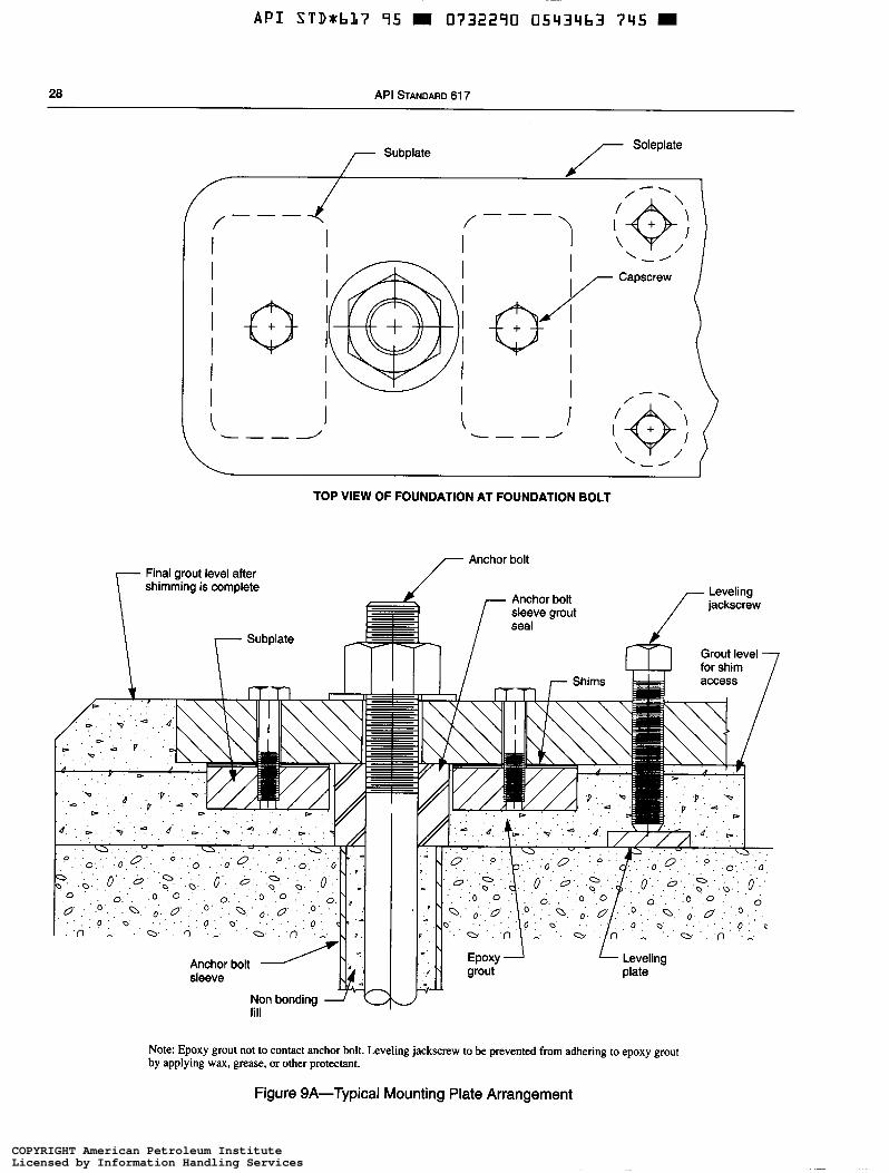
A P I STD*bL7 95 0732290 0543463 745
28 API STANDARD 61 7
/- soleplate Subplate
TOP VIEW OF FOUNDATION AT FOUNDATION BOLT
7 Final grout level aiter r Anchor bolt
shimming is complete
Note: Epoxy grout not to contact anchor bolt. Leveling jackscrew to be prevented from adhering to epoxy grout by applying wax, grease, or other protectant.
Figure 9A-Typical Mounting Plate Arrangement
COPYRIGHT American Petroleum InstituteLicensed by Information Handling ServicesCOPYRIGHT American Petroleum InstituteLicensed by Information Handling Services
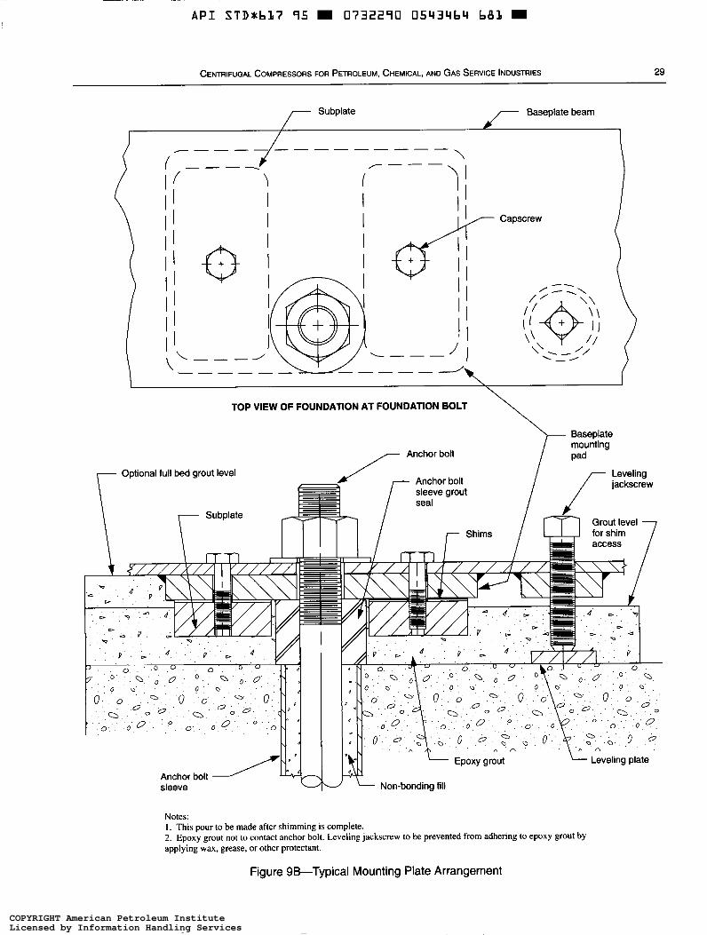
A P I S T D * b L ï 95 0732290 0543464 681 m
CENTRIFUGAL COMPRESSORS FOR PETROLEUM, CHEMICAL, AND GAS SERVICE INDUSTRIES 29
\ --------------
'I i r - - -
f 1 I I
I I
( --- - J I / I I I 1 , Capccrew
I
Subplate Baseplate beam
/ I
\ TOP VIEW OF FOUNDATION AT FOUNDATION BOLT
Baseplate mounting
/- Anchor bo't Optional full bed grout level
O 0 - 0 0 - 0 Q P o o a O o Q
Notes: I . This pour to be made after shimming is complete. 2. Epoxy grout not to contact anchor bolt. Leveling jackscrew to be prevented from adhering to epoxy grout by applying wax, grease, or other protectant.
Figure 9B-Typical Mounting Plate Arrangement
COPYRIGHT American Petroleum InstituteLicensed by Information Handling ServicesCOPYRIGHT American Petroleum InstituteLicensed by Information Handling Services
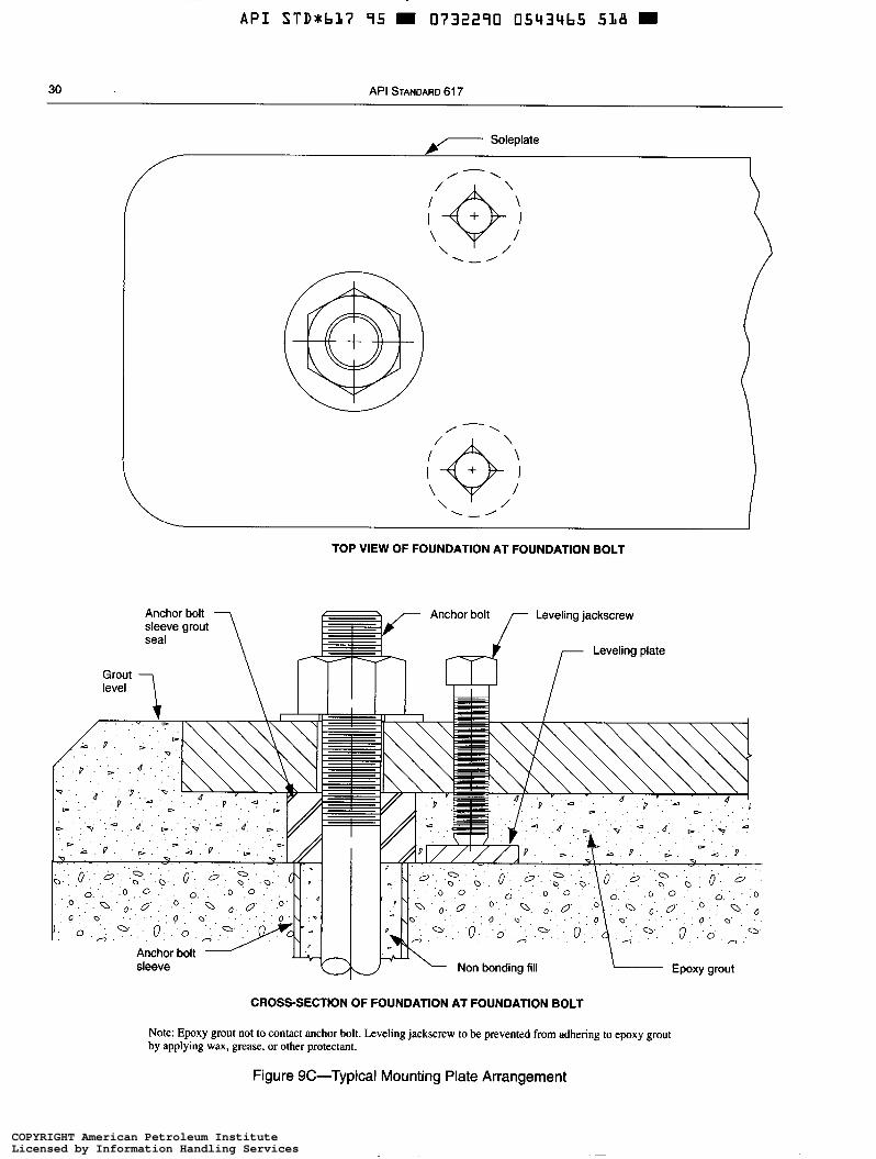
A P I STDrbL7 95 m 0732290 05434b5 5LB m
30 API STANDARD 61 7
TOP VIEW OF FOUNDATION AT FOUNDATION BOLT
Leveling jackscrew
CROSS-SECTION OF FOUNDATION AT FOUNDATION BOLT
Note: Epoxy grout not to contact anchor bolt. Leveling jackscrew to be prevented from adhering to epoxy grout by applying wax, grease, or other protectant.
Figure 9C-Typical Mounting Plate Arrangement
COPYRIGHT American Petroleum InstituteLicensed by Information Handling ServicesCOPYRIGHT American Petroleum InstituteLicensed by Information Handling Services
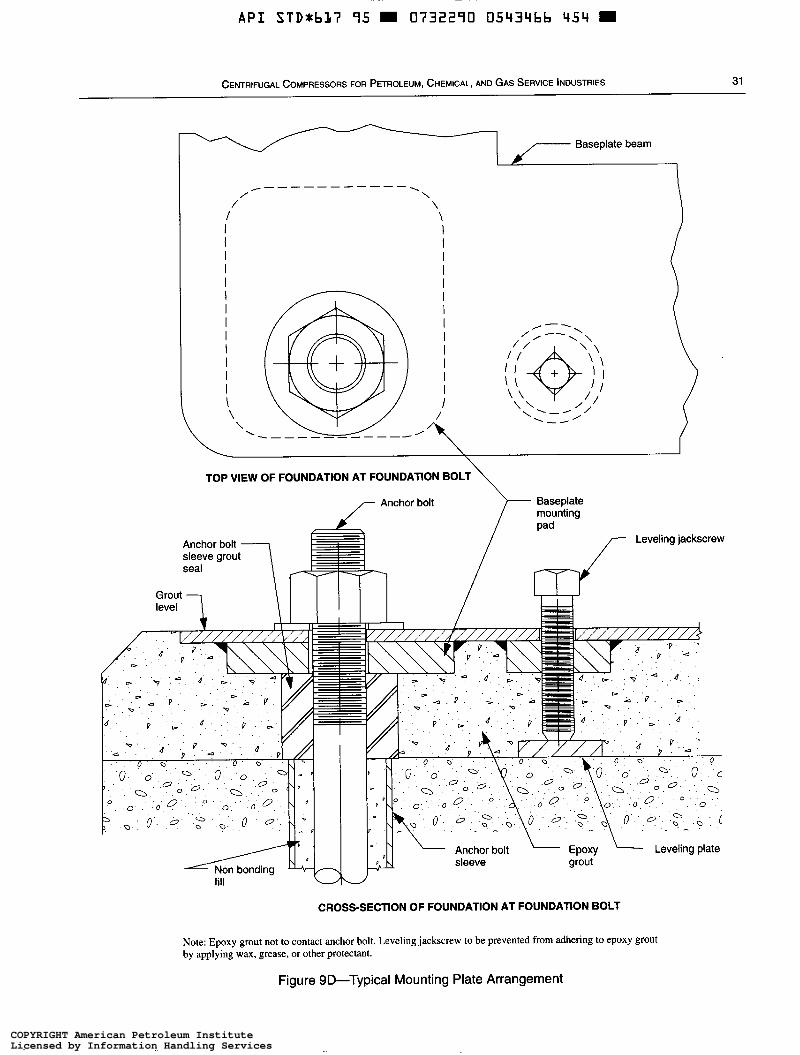
API STD*bLï 95 0732290 0543466 4 5 4 =
CENTRIFUGAL COMPRESSORS FOR PETROLEUM, CHEMICAL, AND GAS SERVICE INDUSTRIES 31
Baseplate beam
y - - - - - - - - - - - \ / \
/ \
I I I l I I I \ \ ?\
I I I I I l I
I
4 \ I
TOP VIEW OF FOUNDATION AT FOUNDATION BOLT\
CROSS-SECTION OF FOUNDATION AT FOUNDATION BOLT
Note: Epoxy grout not to contact anchor bolt. Leveling jackscrew to be prevented from adhering to epoxy grout by applying wax, grease, or other protectant.
Figure 9D-Typical Mounting Plate Arrangement
COPYRIGHT American Petroleum InstituteLicensed by Information Handling ServicesCOPYRIGHT American Petroleum InstituteLicensed by Information Handling Services
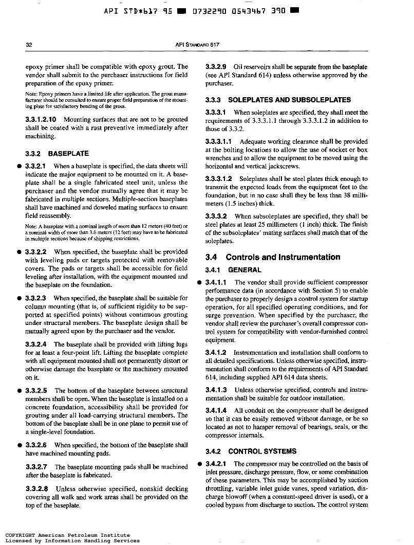
~~ -
A P I STDrbL7 95 W 0732290 05434b7 390 =
32 API STANDARD 617
epoxy primer shall be compatible with epoxy grout. The vendor shall submit to the purchaser instructions for field preparation of the epoxy primer. Note: Epoxy primers have a limited life after application. The grout manu- facturer should be consulted to ensure proper field preparation of the mount- ing plate for satisfactory bonding of the grout.
3.3.1.2.10 Mounting surfaces that are not to be grouted shall be coated with a rust preventive immediately after machining.
3.3.2 BASEPLATE
3.3.2.1 When a baseplate is specified, the data sheets will indicate the major equipment to be mounted on it. A base- plate shall be a single fabricated steel unit, unless the purchaser and the vendor mutually agree that it may be fabricated in multiple sections. Multiple-section baseplates shall have machined and doweled mating surfaces to ensure field reassembly. Note: A baseplate with a nominal length of more than 12 meters (40 feet) or a nominal width of more than 3.6 meters (12 feet) may have to be fabricated in multiple sections because of shipping restrictions.
O 3.3.2.2 When specified, the baseplate shall be provided with leveling pads or targets protected with removable covers. The pads or targets shall be accessible for field leveling after installation, with the equipment mounted and the baseplate on the foundation.
O 3.3.2.3 When specified, the baseplate shall be suitable for column mounting (that is, of sufficient rigidity to be sup- ported at specified points) without continuous grouting under structural members. The baseplate design shall be mutually agreed upon by the purchaser and the vendor.
3.3.2.4 The baseplate shall be provided with lifting lugs for at least a four-point lift. Lifting the baseplate complete with ail equipment mounted shall not permanently distort or otherwise damage the baseplate or the machinery mounted on it.
O 3.3.2.5 The bottom of the baseplate between structural members shall be open. When the baseplate is installed on a concrete foundation, accessibility shall be provided for grouting under all load-carrying structural members. The bottom of the baseplate shall be in one plane to permit use of a single-level foundation.
3.3.2.6 When specified, the bottom of the baseplate shall have machined mounting pads.
3.3.2.7 after the baseplate is fabricated.
3.3.2.8 Unless otherwise specified, nonskid decking covering all walk and work areas shall be provided on the top of the baseplate.
The baseplate mounting pads shall be machined
3.3.2.9 Oil reservoirs shall be separate from the baseplate (see API Standard 614) unless otherwise approved by the purchaser.
3.3.3 SOLEPLATES AND SUBSOLEPLATES
3.3.3.1 When soleplates are specified, they shall meet the requirements of 3.3.3.1.1 through 3.3.3.1.2 in addition to those of 3.3.2.
3.3.3.1.1 Adequate working clearance shall be provided at the bolting locations to allow the use of socket or box wrenches and to allow the equipment to be moved using the horizontal and vertical jackscrews.
3.3.3.1.2 Soleplates shall be steel plates thick enough to transmit the expected loads from the equipment feet to the foundation, but in no case shall they be less than 38 milli- meters (1.5 inches) thick.
3.3.3.2 When subsoleplates are specified, they shall be steel plates at least 25 millimeters (1 inch) thick. The finish of the subsoleplates’ mating surfaces shall match that of the soleplates.
3.4 Controls and Instrumentation 3.4.1 GENERAL
3.4.1.1 The vendor shall provide sufficient compressor performance data (in accordance with Section 5 ) to enable the purchaser to properly design a control system for startup operation, for all specified operating conditions, and for surge prevention. When specified by the purchaser, the vendor shall review the purchaser’s overall compressor con- trol system for compatibility with vendor-furnished control equipment.
3.4.1.2 Instrumentation and installation shall conform to all detailed specifications. Unless otherwise specified, instru- mentation shall conform to the requirements of API Standard 614, including supplied API 614 data sheets.
3.4.1.3 Unless otherwise specified, controls and instru- mentation shall be suitable for outdoor installation.
3.4.1.4 All conduit on the compressor shall be designed so that it can be easily removed without damage, or be so located as not to hamper removal of bearings, seals, or the compressor internals.
3.4.2 CONTROL SYSTEMS
O 3.4.2.1 The compressor may be controlled on the basis of inlet pressure, discharge pressure, flow, or some combination of these parameters. This may be accomplished by suction throttling, variable inlet guide vanes, speed variation, dis- charge blowoff (when a constant-speed dnver is used), or a cooled bypass from discharge to suction. The control system
COPYRIGHT American Petroleum InstituteLicensed by Information Handling ServicesCOPYRIGHT American Petroleum InstituteLicensed by Information Handling Services
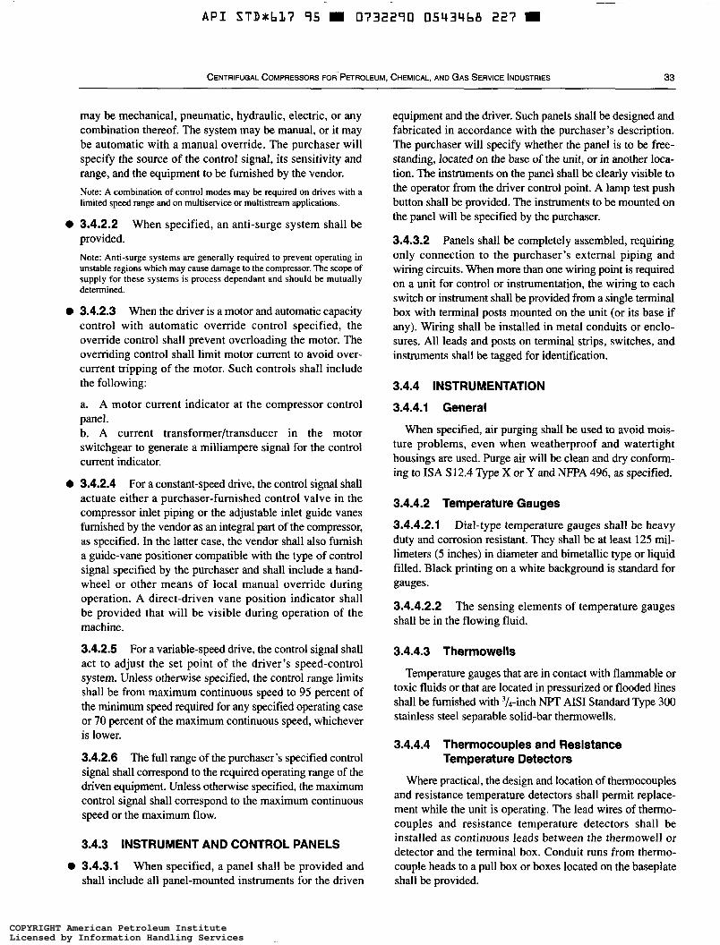
A P I STD*bLî 95 W O732290 0543468 227 =
CENTRIFUGAL COMPRESSORS FOR PETROLEUM, CHEMICAL, AND GAS SERVICE INDUSTRIES 33
may be mechanical, pneumatic, hydraulic, electric, or any combination thereof. The system may be manual, or it may be automatic with a manual override. The purchaser will specify the source of the control signal, its sensitivity and range, and the equipment to be furnished by the vendor. Note: A combination of control modes may be required on drives with a limited speed range and on multiservice or multistream applications.
3.4.2.2 provided.
When specified, an anti-surge system shall be
Note: Anti-surge systems are generally required to prevent operating in unstable regions which may cause damage to the compressor. The scope of supply for these systems is process dependant and should be mutually determined.
3.4.2.3 When the driver is a motor and automatic capacity control with automatic override control specified, the override control shall prevent overloading the motor. The overriding control shall limit motor current to avoid over- current tripping of the motor. Such controls shall include the following:
a. A motor current indicator at the compressor control panel. b. A current transformer/transducer in the motor switchgear to generate a milliampere signal for the control current indicator.
3.4.2.4 For a constant-speed drive, the control signal shall actuate either a purchaser-furnished control valve in the compressor inlet piping or the adjustable inlet guide vanes furnished by the vendor as an integral part of the compressor, as specified. In the latter case, the vendor shall also furnish a guide-vane positioner compatible with the type of control signal specified by the purchaser and shall include a hand- wheel or other means of local manual override during operation. A direct-driven vane position indicator shall be provided that will be visible during operation of the machine.
3.4.2.5 For a variable-speed drive, the control signal shall act to adjust the set point of the driver’s speed-control system. Unless otherwise specified, the control range limits shall be from maximum continuous speed to 95 percent of the minimum speed required for any specified operating case or 70 percent of the maximum continuous speed, whichever is lower.
3.4.2.6 The full range of the purchaser’s specified control signal shall correspond to the required operating range of the driven equipment. Unless otherwise specified, the maximum control signal shall correspond to the maximum continuous speed or the maximum flow.
3.4.3 INSTRUMENT AND CONTROL PANELS
equipment and the driver. Such panels shall be designed and fabricated in accordance with the purchaser’s description. The purchaser will specify whether the panel is to be free- standing, located on the base of the unit, or in another loca- tion. The instruments on the panel shall be clearly visible to the operator from the driver control point. A lamp test push button shall be provided. The instruments to be mounted on the panel will be specified by the purchaser.
3.4.3.2 Panels shall be completely assembled, requiring only connection to the purchaser’s external piping and wiring circuits. When more than one wiring point is required on a unit for control or instrumentation, the wiring to each switch or instrument shall be provided from a single terminal box with terminal posts mounted on the unit (or its base if any). Wiring shall be installed in metal conduits or enclo- sures. All leads and posts on terminal strips, switches, and instruments shall be tagged for identification.
3.4.4 INSTRUMENTATION
3.4.4.1 General
When specified, air purging shall be used to avoid mois- ture problems, even when weatherproof and watertight housings are used. Purge air will be clean and dry conform- ing to ISA S 12.4 Type X or Y and NFPA 496, as specified.
3.4.4.2 Temperature Gauges
3.4.4.2.1 Dial-type temperature gauges shall be heavy duty and corrosion resistant. They shall be at least 125 mil- limeters (5 inches) in diameter and bimetallic type or liquid filled. Black printing on a white background is standard for gauges.
3.4.4.2.2 shall be in the flowing fluid.
The sensing elements of temperature gauges
3.4.4.3 Thermowells
Temperature gauges that are in contact with flammable or toxic fluids or that are located in pressurized or flooded lines shall be furnished with 3/4-inch NPT AIS1 Standard Type 300 stainless steel separable solid-bar thermowells.
3.4.4.4 Thermocouples and Resistance Temperature Detectors
Where practical, the design and location of thermocouples and resistance temperature detectors shall permit replace- ment while the unit is operating. The lead wires of thermo- couples and resistance temperature detectors shall be installed as continuous leads between the thermowell or detector and the terminal box. Conduit runs from thermo-
3.4.3.1 When specified, a panel shall be provided and shall include all panel-mounted instruments for the driven
couple heads to a pull box or boxes located on the baseplate shall be provided.
COPYRIGHT American Petroleum InstituteLicensed by Information Handling ServicesCOPYRIGHT American Petroleum InstituteLicensed by Information Handling Services
~
A P I STDxbL7 95 0732290 0543469 163
34 API STANDARD 617
3.4.4.5 Pressure Gauges
Pressure gauges (not including built-in instrument air gauges) shall be furnished with AISI Standard Type 316 stainless steel bourdon tubes and stainless steel movements, 114-millimeter (4'/2-inch) dials [ 152-millimeter (6-inch) dials for the range over 5500 kPa (800 pounds per square inch)] and '&inch National Pipe Thread (NPT) male alloy steel connections. Black printing on a white background is standard for gauges. When specified, liquid-filled gauges shall be furnished in locations subject to vibration. Gauge ranges shall preferably be selected so that the normal oper- ating pressure is at the middle of the gauge's range. In no case, however, shall the maximum reading on the dial be less than the applicable relief valve setting plus 10 percent. Each pressure gauge shall be provided with a device such as a disk insert or blowout back designed to relieve excess case pressure.
3.4.4.6 Solenoid Valves
3.4.4.6.1 Direct solenoid-operated valves shall be used only in clean, dry instrument-air service, shall have Class F insulation or better, and shall have a continuous service rat- ing. When required for other services, the solenoid shall act as a pilot valve to pneumatic or hydraulic valves.
3.4.4.6.2 Solenoid valves shall not be used in continuous services that may affect normal operations, such as fuel controls. They may be used in intermittent instrument services, such as starting-cycle controls.
3.4.5 ALARMS AND SHUTDOWNS
3.4.5.1 General
3.4.5.1.1 Each alarm switch and each shutdown switch shall be furnished in a separate housing located to facilitate inspection and maintenance. Hermetically sealed, single pole, double-throw switches with a minimum capacity of 5 amperes at 120 volts AC and ampere at 120 volts DC shall be used. Mercury switches shall not be used.
3.4.5.1.2 Unless otherwise specified, electric switches that open (deenergize) to alarm and close (energize) to trip shall be furnished by the vendor.
3.4.5.1.3 The sequence of alarm and shutdown operation shall be as described in 3.4.5.1.3.1 through 3.4.5.1.3.5.
3.4.5.1.3.1 Any alarm or shutdown condition shall be initiated by the action of field contacts.
3.4.5.1.3.2 Alarm and shutdown indications shall consist of corresponding panel-light illumination and sounding of a horn.
3.4.5.1.3.3 Acknowledgment of the alarm or shutdown condition shall be accomplished by operating a common
horn silence push button suitably located on the panel. This shall silence the horn.
3.4.5.1.3.4 After the alarmed field condition has been corrected, the corresponding panel alarm light shall remain lit until a common panel-mounted reset push button is oper- ated (a manual reset). In the interim, any additional field alarm condition or conditions will again sound the horn and illuminate the corresponding additional panel light or lights.
3.4.5.1.3.5 Shutdown panel lights shall contain a first-out feature (that is, only the first shutdown light shall be illumi- nated). After a shutdown occurs, operation of the reset push button shall be required before the unit can be restarted.
3.4.5.1.4 Connections shall be provided to actuate a remote alarm when any of the locally displayed compressor alarms or shutdowns operate.
O 3.4.5.1.5 When specified, the vendor shall furnish a first out annunciator in accordance with ANSVISA-S 18.1-1979. The sequence configuration shall be as specified.
3.4.5.2 Alarm and Trip Switches
3.4.5.2.1 Alarm and trip-switch settings shall not be adjustable from outside the housing. Alarm and trip switches shall be arranged to permit testing of the control circuit, including, when possible, the actuating element, without interfering with normal operation of the equipment. The vendor shall provide a clearly visible light on the panel to indicate when trip circuits are in a test bypass mode. Unless otherwise specified, shutdown systems shall be provided with switches or another suitable means to permit testing without shutting down the unit.
3.4.5.2.2 Pressure-sensing elements shall be of AISI Standard Qpe 300 stainless steel. Low-pressure alarms shall be equipped with a valved bleed or vent connection to allow controlled depressurizing so that the operator can note the alarm set pressure on the associated pressure gauge. High- pressure alarms shall be equipped with valved test connec- tions so that a portable test pump can be used to raise the pressure.
3.4.5.3 Removal of Instruments and Controls
All instruments and controls other than shutdown sensing devices shall be installed with sufficient valving to permit their removal while the system is in operation.
3.4.5.4 Housings for Arcing Switches
Particular attention is called to the requirements of 2.1.15 concerning the characteristics of housings for arcing switches outlined in the applicable codes.
COPYRIGHT American Petroleum InstituteLicensed by Information Handling ServicesCOPYRIGHT American Petroleum InstituteLicensed by Information Handling Services
~~
A P I STDxbL7 95 H 0732290 0543470 9155
CENTRIFUGAL COMPRESSORS FOR PETROLEUM, CHEMICAL, AND GAS SERVICE INDUSTRIES 35
3.4.6 ELECTRICAL SYSTEMS
O 3.4.6.1 The Characteristics of electrical power supplies for motors, heaters, and instrumentation will be specified. A pilot light shall be provided on the incoming side of each supply circuit to indicate that the circuit is energized. The pilot lights shall be installed on the control panels.
0 3.4.6.2 Electrical equipment located on the unit or on any separate panel shall be suitable for the hazard classification specified (see 2.1.14). Electrical starting and supervisory controls may be either AC or DC.
3.4.6.3 Power and control wiring within the confines of the baseplate shall be resistant to heat, moisture, and abra- sion. Stranded conductors shall be used within the confines of the baseplate and in other areas subject to vibration. Measurement and remote-control panel wiring may be solid conductor. Where elastomer insulation is used, a Neoprene or equivalent high-temperature thermo-plastic sheath shall be provided for insulation protection. Wiring shall be suit- able for environmental temperatures.
3.4.6.4 Unless otherwise specified, all leads on terminal strips, switches, and instruments shall be permanently tagged for identification. All terminal boards in junction boxes and control panels shall have at least 20 percent spare terminal points.
3.4.6.5 To facilitate maintenance, liberal clearances shall be provided for all energized parts (such as terminal blocks and relays) on equipment. The clearances required for 600 volt service shall also be provided for lower voltages. To guard against accidental contact, enclosures shall be pro- vided for all energized parts.
Electrical materials including insulation shall be corrosion resistant and nonhygroscopic insofar as is possible. When specified for tropical location, materials shall be given the treatments specified in 3.4.6.6.1 and 3.4.6.6.2.
3.4.6.6.1 Parts (such as coils and windings) shall be protected from fungus attack.
3.4.6.6.2 corrosion by plating or another suitable coating.
3.4.6.7 Control, instrumentation, and power wiring (including temperature element leads) within the limits of the baseplate shall be installed in rigid metallic conduits and boxes, properly bracketed to minimize vibration and isolated or shielded to prevent interference between voltage levels. Conduits may terminate (and in the case of temperature ele- ment heads, shall terminate) with a flexible metallic conduit long enough to permit access to the unit for maintenance without removal of the conduit. If temperature element heads will be exposed to temperatures above 60°C (140"F), a 19-millimeter (3/,-inch) bronze hose with four-wall
O 3.4.6.6
Unpainted surfaces shall be protected from
interlocking construction and joints with packed on (heat- proof) couplings shall be used.
3.4.6.8 For Division 2 locations, flexible metallic con- duits shall have a liquidtight thermosetting or thermoplastic outer jacket. For Division 1 locations, an NFPA-approved connector shall be provided.
3.4.7 VIBRATION, POSITION, AND BEARING TEMPERATURE DETECTORS
3.4.7.1 Unless otherwise specified, radial shaft vibration and axial-position transducers and bearing temperature sensors shall be supplied, installed, and calibrated in accor- dance with API Standard 670.
3.4.7.2 When specified, radial shaft vibration and axial- position monitors shall be supplied and calibrated in accor- dance with API Standard 670.
Purchaser will specify type of temperature detec- O 3.4.7.3 tor required per 2.7. i .2.
When specified, a bearing-temperature monitor shall be supplied and calibrated according to API Standard 670 (see 2.7.1.2).
When specified, casing vibration transducers shall be supplied, installed, and calibrated in accordance with API Standard 670.
3.4.7.4
0 3.4.7.5
3.4.7.6 When specified, casing vibration monitors shall be supplied, installed and calibrated in accordance with API Standard 670.
3.5 Piping and Appurtences 3.5.1 GENERAL
3.5.1.1 piping provided by the vendor.
3.5.1.2 that are in the following services:
a. Instrument and control air. b. Lubricating oil. c. Control oil. d. Seal fluid. e. Cooling water. f. Balance gas. g. Reference gas. h. Buffer gas. i. Drains. j. Liquid injection. Note: Casing connections are discussed in 2.4.
API Standard 614 shall apply to all auxiliary
Auxiliary systems are defined as piping systems
0 3.5.1.3 When a baseplate has been specified, the vendor shall furnish all piping systems, including mounted appur- tenances, located within its confines. The piping shall
COPYRIGHT American Petroleum InstituteLicensed by Information Handling ServicesCOPYRIGHT American Petroleum InstituteLicensed by Information Handling Services
A P I STDxb37 95 0732290 0543473 BI3 =
36 API STANDARD 61 7
terminate with flanged connections at the edge of the base- plate. When soleplates are specified, the extent of the piping system supplied by the vendor shall be defined by the pur- chaser. The purchaser will furnish only interconnecting pip- ing between equipment groupings and off base facilities.
3.5.1.4 valves at the points of measurement.
Instrument lines shall be provided with shutoff
O 3.5.1.5 When specified, a liquid injection manifold shall be supplied. It shall include a throttle valve, an armored flow meter, a check valve, a pressure indicator, and a block valve for each injection point.
O 3.5.1.6 When a buffer-gas manifold is specified, the required components such as valves, flow meters, check valves, pressure indicators, throttle valves, differential pressure indicators, controllers, and control valves shall be furnished by the vendor.
a common connection. Where a pressure gauge is to be used for testing pressure alarm or shutdown switches, common connections are required for the pressure gauge and switches.
3.5.3 PROCESS PIPING
O 3.5.3.1 The extent and requirements for process piping to be supplied by the vendor will be specified.
When specified, the vendor shall review all pip- ing, appurtenances (intercoolers, aftercoolers, separators, knockout drums, air intake filters, and expansion joints), and vessels immediately upstream and downstream of the equip- ment and supports. The purchaser and the vendor shall mutually agree on the scope of this review. Note: Piping arrangements may affect stable operation.
O 3.5.3.2
3.6 Special Tools 3.5.1.7 Provision for bypassing the bearings (and seals if applicable) of ComPressors and drivers during Oil system flushing operations shall be provided.
3.5.2 INSTRUMENT PIPING
3.6.1 When special tools and fixtures are required to dis- assemble, assemble, or maintain the unit, they shall be included in the quotation and furnished as part of the initial supply of the machine. For multiunit installations, the requirements for quantities of special tools and fixtures shall bemutually agreed upon by the purchaser and the vendor. These or similar special tools shall be used during shop assembly and post-test disassembly of the equipment.
Connections on equipment and piping for pressure instru- ments and test points shall conform to API Standard 614. Beyond the initial 3/4-inch valve, ‘/*-inch piping, valves, and _ _ - fittings may be used. Where convenient, a common con- nection may be used for remotely mounted instruments that measure the same pressure. Separate secondary ‘/*-inch isolating valves are required for each instrument on
3.6.2 When special tools are provided, they shall be pack- aged in separate, rugged boxes and marked “Special Tools for (taditem number).” Each tool shall be stamped or tagged to indicate its intended use.
SECTION 4-INSPECTIONy TESTING, AND PREPARATION FOR SHIPMENT
4.1 General 4.1.1 After advance notification of the vendor by the pur- chaser, the purchaser’s representative shall have entry to all vendor and subvendor plants where manufacturing, testing, or inspection of the equipment is in progress.
be carried out with the purchaser or his representative in at- tendance. For mechanical running or performance tests, this requires written notification of a successful prelimi- nary test.
4.1.4.3 Observed means that the purchaser shall be noti- fied of the timing of the inspection or test; however, the inspection or test shall be performed as scheduled, and if the purchaser or his representative is not present, the vendor
4.1.2 chaser’s inspection and testing requirements.
The vendor shall notify subvendors of the pur-
4.1 -3 The vendor shall provide sufficient advance notice to the purchaser before conducting any inspection or test that the purchaser has specified to be witnessed or observed.
The purchaser will specify the extent of his partici- pation in the inspection and testing.
shall proceed to the next step. (nie purchaser should expect to be in the factory longer than for a witnessed test.)
4.1.5 shall be provided by the vendor.
Equipment for the specified inspection and tests O 4.1.4
- 0 4.1.6 When specified, the purchaser’s representative, the
vendor,s representative or both shall indicate in accordance with the inspector’s checklist (Appendix .H) by
4.1.4.1 dinate manufacturing hold points and inspectors’ visits.
The purchaser and the vendor shall meet to coor-
4.1.4.2 Witnessed means that a hold shall be applied to the production schedule and that the inspection or test shall
initialing, dating, and submitting the completed form before shipment.
COPYRIGHT American Petroleum InstituteLicensed by Information Handling ServicesCOPYRIGHT American Petroleum InstituteLicensed by Information Handling Services
A P I STD+bL7 95 W 0732290 0543472 758 =
CENTRIFUGAL COMPRESSORS FOR PETROLEUM, CHEMICAL, AND GAS SERVICE INDUSTRIES 37
4.1.7 the vendor’s quality control program for review.
The purchaser’s representative shall have access to
4.2 Inspection 4.2.1 GENERAL
4.2.1.1 The vendor shall keep the following data available for at least five years for examination by the purchaser or his representative upon request:
a. Necessary certification of materials, such as mill test reports. b. Purchase specifications for all items on bills of materials. c. Test data to verify that the requirements of the specifica- tion have been met. d. Fully identified records of all heat treatment, whether performed in the normal course of manufacture or as part of a repair procedure. e. Results of quality-control tests and inspections. f. Running test data (see 4.3.4). g. Final-assembly maintenance and running clearances.
4.2.1.2 Pressure-containing parts shall not be painted until the specified inspection of the parts is completed.
4.2.1.3 The purchaser will specify the following:
a. Parts that shall be subjected to surface and subsurface examination. b. The type of examination required, such as magnetic particle, liquid penetrant, radiographic, or ultrasonic examination.
4.2.1.4 During assembly of the compressor and before testing, each component (including cast in passages of these components) and all piping and appurtenances shall be cleaned by pickling or by another appropriate method to re- move foreign materials, corrosion products, and mill scale.
4.2.1.5 When specified, the purchaser may inspect for cleanliness of the equipment and all piping and appurte- nances furnished by or through the vendor before heads are welded to vessels, openings in vessels or exchangers are closed, or piping is finally assembled.
4.2.1.6 When specified, the hardness of parts, welds, and heat-affected zones shall be verified as being within the allowable values by testing of the parts, welds, or heat affected zones. The method, extent, documentation, and witnessing of the testing shall be mutually agreed upon by the purchaser and the vendor.
4.2.2 MATERIAL INSPECTION
4.2.2.1 General
4.2.2.1.1 When radiographic, ultrasonic, magnetic par- ticle, or liquid penetrant inspection of welds or materials is specified, the recommended practices in 4.2.2.2 through
4.2.2.5 shall apply unless other procedures are specified by the purchaser. Cast iron may be inspected in accordance with 4.2.2.4 and 4.2.2.5. Welds, cast steel, and wrought material may be inspected in accordance with 4.2.2.2 through 4.2.2.5. The material inspection of pressure-containing parts is covered in 2.1 1.2 and 2.1 1.4; impellers, in 2.11.5. Note: These recommended practices describe examination techniques that are applicable to great varieties of sizes and shapes of materials and widely varying examination requirements. Since the specification for the actual component being inspected depends on metallurgy, component configura- tion, and method of manufacture, specific procedures and acceptance stan- dards for the application should be covered by written standards, developed by the manufacturer for the specific application.
4.2.2.1.2 Acceptance standards for 4.2.2.2 through 4.2.2.5 shall be mutually agreed upon between the purchaser and vendor.
4.2.2.2 Radiographic Inspections
ASTM Standard Practices E94. Radiography shall be based upon the procedures of
4.2.2.3 Ultrasonic Inspection
Ultrasonic inspection shall be based upon the procedures ASTM A609 (castings), ASTM A388 (forgings), or ASTM A578 (plate).
4.2.2.4 Magnetic Particle Inspection
Both wet and dry methods of magnetic particle inspection shall be based upon the procedures of ASTM Standard Prac- tice E 709.
4.2.2.5 Liquid Penetrant Inspection
dures of ASTM E 165. Liquid penetrant inspection shall be based upon the proce-
4.3 Testing 4.3.1 GENERAL
4.3.1.1 Equipment shall be tested in accordance with 4.3.2 through 4.3.5. Other tests that may be specified by the purchaser are described in 4.3.6. Note: See Appendix I for typical gas seal testing considerations.
4.3.1.2 At least six weeks before the first scheduled test, the vendor shall submit to the purchaser, for his review and comment, detailed procedures for all running tests, including acceptance criteria for all monitored parameters.
4.3.1.3 The vendor shall notify the purchaser not less than five working days before the date the equipment will be ready for testing. If the testing is rescheduled, the vendor shall notify the purchaser not less than five working days before the new test date.
COPYRIGHT American Petroleum InstituteLicensed by Information Handling ServicesCOPYRIGHT American Petroleum InstituteLicensed by Information Handling Services
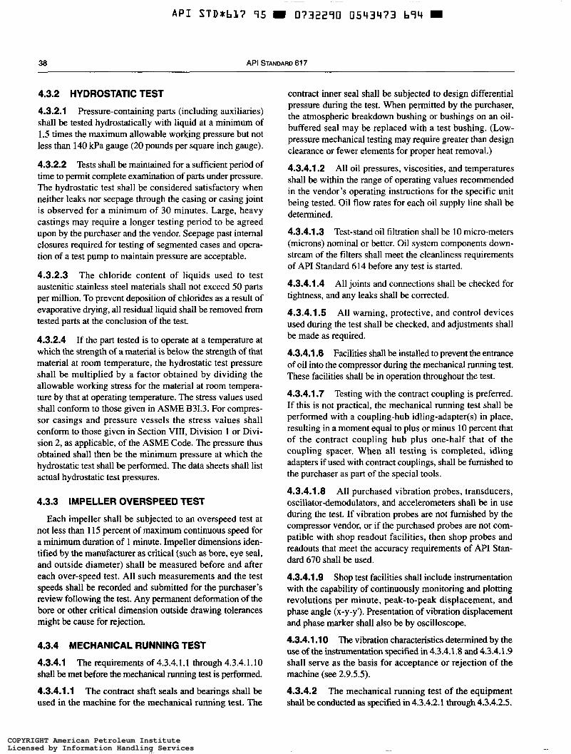
38 API STANDARD 61 7
4.3.2 HYDROSTATIC TEST
4.3.2.1 Pressure-containing parts (including auxiliaries) shall be tested hydrostatically with liquid at a minimum of 1.5 times the maximum allowable working pressure but not less than 140 kPa gauge (20 pounds per square inch gauge).
4.3.2.2 Tests shall be maintained for a sufficient period of time to permit complete examination of parts under pressure. The hydrostatic test shall be considered satisfactory when neither leaks nor seepage through the casing or casing joint is observed for a minimum of 30 minutes. Large, heavy castings may require a longer testing period to be agreed upon by the purchaser and the vendor. Seepage past internal closures required for testing of segmented cases and opera- tion of a test pump to maintain pressure are acceptable.
4.3.2.3 The chloride content of liquids used to test austenitic stainless steel materials shall not exceed 50 parts per million. To prevent deposition of chlorides as a result of evaporative drying, all residual liquid shall be removed from tested parts at the conclusion of the test.
4.3.2.4 If the part tested is to operate at a temperature at which the strength of a material is below the strength of that material at room temperature, the hydrostatic test pressure shall be multiplied by a factor obtained by dividing the allowable working stress for the material at room tempera- ture by that at operating temperature. The stress values used shall conform to those given in ASME B31.3. For compres- sor casings and pressure vessels the stress values shall conform to those given in Section VIII, Division 1 or Divi- sion 2, as applicable, of the ASME Code. The pressure thus obtained shall then be the minimum pressure at which the hydrostatic test shall be performed. The data sheets shall list actual hydrostatic test pressures.
4.3.3 IMPELLER OVERSPEED TEST
Each impeller shall be subjected to an overspeed test at not less than 115 percent of maximum continuous speed for a minimum duration of 1 minute. Impeller dimensions iden- tified by the manufacturer as critical (such as bore, eye seal, and outside diameter) shall be measured before and after each over-speed test. All such measurements and the test speeds shall be recorded and submitted for the purchaser’s review following the test. Any permanent deformation of the bore or other critical dimension outside drawing tolerances might be cause for rejection.
4.3.4 MECHANICAL RUNNING TEST
4.3.4.1 The requirements of 4.3.4.1.1 through 4.3.4.1.10 shall be met before the mechanical running test is performed.
4.3.4.1.1 The contract shaft seals and bearings shall be used in the machine for the mechanical running test. The
contract inner seal shall be subjected to design differential pressure during the test. When permitted by the purchaser, the atmospheric breakdown bushing or bushings on an oil- buffered seal may be replaced with a test bushing. (Low- pressure mechanical testing may require greater than design clearance or fewer elements for proper heat removal.)
4.3.4.1.2 All oil pressures, viscosities, and temperatures shall be within the range of operating values recommended in the vendor’s operating instructions for the specific unit being tested. Oil flow rates for each oil supply line shall be determined.
4.3.4.1.3 Test-stand oil filtration shall be 10 micro-meters (microns) nominal or better. Oil system components down- stream of the filters shall meet the cleanliness requirements of API Standard 614 before any test is started.
4.3.4.1.4 All joints and connections shall be checked for tightness, and any leaks shall be corrected.
4.3.4.1.5 All warning, protective, and control devices used during the test shall be checked, and adjustments shall be made as required.
4.3.4.1.6 Facilities shall be installed to prevent the entrance of oil into the compressor during the mechanical running test. These facilities shall be in operation throughout the test.
4.3.4.1.7 Testing with the contract coupling is preferred. If this is not practical, the mechanical running test shall be performed with a coupling-hub idling-adapter(s) in place, resulting in a moment equal to plus or minus 10 percent that of the contract coupling hub plus one-half that of the coupling spacer. When all testing is completed, idling adapters if used with contract couplings, shall be furnished to the purchaser as part of the special tools.
4.3.4.1.8 All purchased vibration probes, transducers, oscillator-demodulators, and accelerometers shall be in use during the test. If vibration probes are not furnished by the compressor vendor, or if the purchased probes are not com- patible with shop readout facilities, then shop probes and readouts that meet the accuracy requirements of API Stan- dard 670 shall be used.
4.3.4.1.9 Shop test facilities shall include instrumentation with the capability of continuously monitoring and plotting revolutions per minute, peak-to-peak displacement, and phase angle (x-y-y’). Presentation of vibration displacement and phase marker shall also be by oscilloscope.
4.3.4.1.1 O The vibration characteristics determined by the use of the insirumentation specified in 4.3.4.1.8 and 4.3.4.1.9 shall serve as the basis for acceptance or rejection of the machine (see 2.9.5.5).
4.3.4.2 The mechanical running test of the equipment shall be conducted as specified in 4.3.4.2.1 through 4.3.4.2.5.
COPYRIGHT American Petroleum InstituteLicensed by Information Handling ServicesCOPYRIGHT American Petroleum InstituteLicensed by Information Handling Services
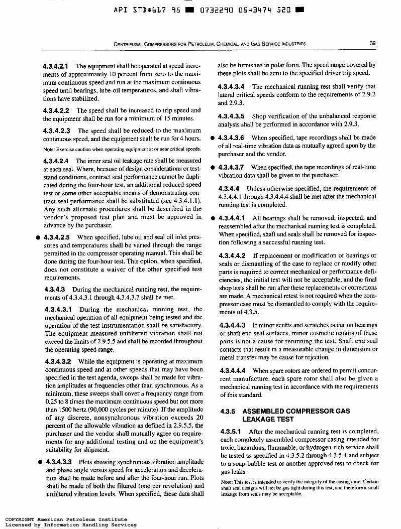
~~ ~ ~
A P I STDxbL7 95 W 0732290 0543474 520 m
CENTRIFUGAL COMPRESSORS FOR PETROLEI JM, CHEMICAL, AND GAS SERVICE INDUSTRIES 39
4.3.4.2.1 The equipment shall be operated at speed incre- ments of approximately 10 percent from zero to the maxi- mum continuous speed and run at the maximum continuous speed until bearings, lube-oil temperatures, and shaft vibra- tions have stabilized.
4.3.4.2.2 The speed shall be increased to trip speed and the equipment shall be run for a minimum of 15 minutes.
4.3.4.2.3 The speed shall be reduced to the maximum continuous speed, and the equipment shall be run for 4 hours. Note: Exercise caution when operating equipment at or near critical speeds.
4.3.4.2.4 The inner seal oil leakage rate shall be measured at each seal. Where, because of design considerations ortest- stand conditions, contract seal performance cannot be dupli- cated during the four-hour test, an additional reduced-speed test or some other acceptable means of demonstrating con- tract seal performance shall be substituted (see 4.3.4.1.1). Any such alternate procedures shall be described in the vendor’s proposed test plan and must be approved in advance by the purchaser.
When specified, lube oil and seal oil inlet pres- sures and temperatures shall be varied through the range permitted in the compressor operating manual. This shall be done during the four-hour test. This option, when specified, does not constitute a waiver of the other specified test requirements.
4.3.4.3 During the mechanical running test, the require- ments of 4.3.4.3.1 through 4.3.4.3.7 shall be met.
4.3.4.3.1 During the mechanical running test, the mechanical operation of all equipment being tested and the operation of the test instrumentation shall be satisfactory. The equipment measured unfiltered vibration shall not exceed the limits of 2.9.5.5 and shall be recorded throughout the operating speed range.
4.3.4.3.2 While the equipment is operating at maximum continuous speed and at other speeds that may have been specified in the test agenda, sweeps shall be made for vibra- tion amplitudes at frequencies other than synchronous. As a minimum, these sweeps shall cover a frequency range from 0.25 to 8 times the maximum continuous speed but not more than 1500 hertz (90,000 cycles per minute). If the amplitude of any discrete, nonsynchronous vibration exceeds 20 percent of the allowable vibration as defined in 2.9.5.5, the purchaser and the vendor shall mutually agree on require- ments for any additional testing and on the equipment’s suitability for shipment.
Plots showing synchronous vibration amplitude and phase angle versus speed for acceleration and decelera- tion shall be made before and after the four-hour run. Plots shall be made of both the filtered (one per revolution) and unfiltered vibration levels. When specified, these data shall
O 4.3.4.2.5
O 4.3.4.3.3
also be furnished in polar form. The speed range covered by these plots shall be zero to the specified driver trip speed.
4.3.4.3.4 The mechanical running test shall verify that lateral critical speeds conform to the requirements of 2.9.2 and 2.9.3.
4.3.4.3.5 analysis shall be performed in accordance with 2.9.3.
Shop verification of the unbalanced response
O 4.3.4.3.6 When specified, tape recordings shall be made of all real-time vibration data as mutually agreed upon by the purchaser and the vendor.
O 4.3.4.3.7 When specified, the tape recordings of real-time vibration data shall be given to the purchaser.
4.3.4.4 Unless otherwise specified, the requirements of 4.3.4.4.1 through 4.3.4.4.4 shall be met after the mechanical running test is completed.
O 4.3.4.4.1 All bearings shall be removed, inspected, and reassembled after the mechanical running test is completed. When specified, shaft end seals shall be removed for inspec- tion following a successful running test.
4.3.4.4.2 If replacement or modification of bearings or seals or dismantling of the case to replace or modify other parts is required to correct mechanical or performance defi- ciencies, the initial test will not be acceptable, and the final shop tests shall be run after these replacements or corrections are made. A mechanical retest is not required when the com- pressor case must be dismantled to comply with the require- ments of 4.3.5.
4.3.4.4.3 If minor scuffs and scratches occur on bearings or shaft end seal surfaces, minor cosmetic repairs of these parts is not a cause for rerunning the test. Shaft end seal contacts that result in a measurable change in dimension or metal transfer may be cause for rejection.
4.3.4.4.4 When spare rotors are ordered to permit concur- rent manufacture, each spare rotor shall also be given a mechanical running test in accordance with the requirements of this standard.
4.3.5 ASSEMBLED COMPRESSOR GAS LEAKAGE TEST
4.3.5.1 After the mechanical running test is completed, each completely assembled compressor casing intended for toxic, hazardous, flammable, or hydrogen-rich service shall be tested as specified in 4.3.5.2 through 4.3.5.4 and subject to a soap-bubble test or another approved test to check for gas leaks. Note: This test is intended to verify the integrity of the casing joint. Certain shaft seal designs will not be gas tight during this test, and therefore a small leakage from seals may be acceptable.
COPYRIGHT American Petroleum InstituteLicensed by Information Handling ServicesCOPYRIGHT American Petroleum InstituteLicensed by Information Handling Services
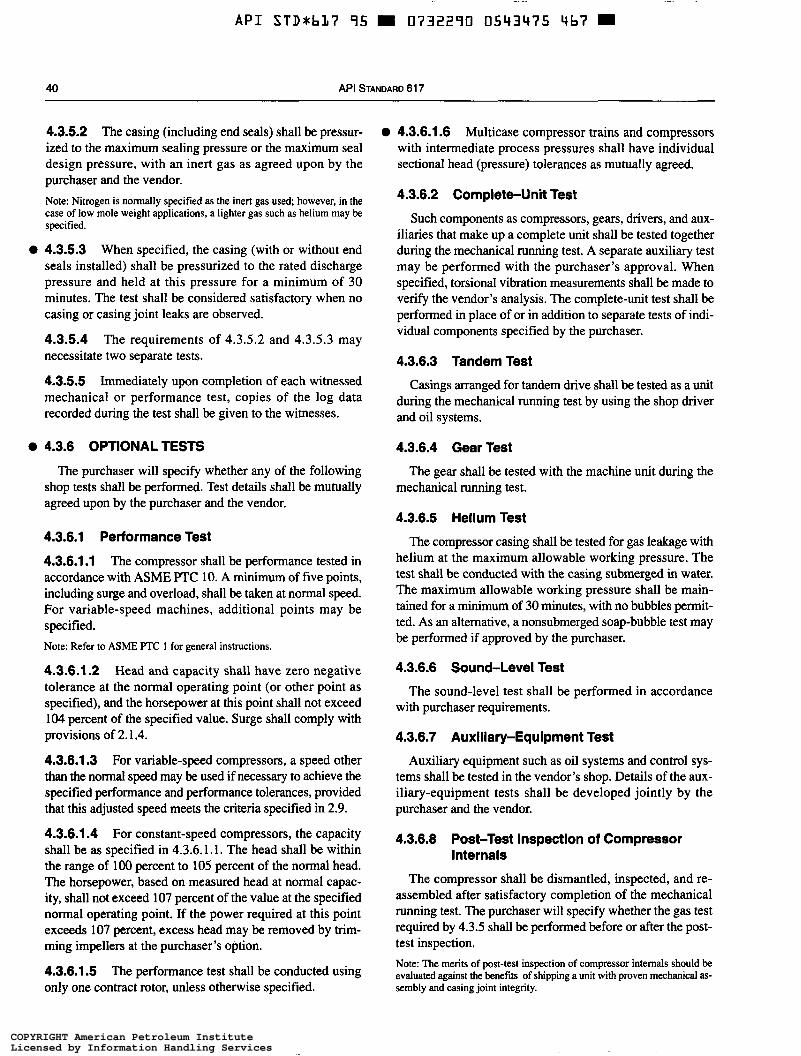
A P I STDJhL7 95 O732290 0543475 4b7
40 API STANDARD 61 7
4.3.5.2 The casing (including end seals) shall be pressur- ized to the maximum sealing pressure or the maximum seal design pressure, with an inert gas as agreed upon by the purchaser and the vendor. Note: Nitrogen is normally specified as the inert gas used; however, in the case of low mole weight applications, a lighter gas such as helium may be specified.
4.3.5.3 When specified, the casing (with or without end seals installed) shall be pressurized to the rated discharge pressure and held at this pressure for a minimum of 30 minutes. The test shall be considered satisfactory when no casing or casing joint leaks are observed.
4.3.5.4 The requirements of 4.3.5.2 and 4.3.5.3 may necessitate two separate tests.
4.3.5.5 Immediately upon completion of each witnessed mechanical or performance test, copies of the log data recorded during the test shall be given to the witnesses.
4.3.6 OPTIONAL TESTS
The purchaser will specify whether any of the following shop tests shall be performed. Test details shall be mutually agreed upon by the purchaser and the vendor.
4.3.6.1 Performance Test
4.3.6.1.1 The compressor shall be performance tested in accordance with ASME PTC 10. A minimum of five points, including surge and overload, shall be taken at normal speed. For variable-speed machines, additional points may be specified. Note: Refer to ASME ITC 1 for general instructions.
4.3.6.1.2 Head and capacity shall have zero negative tolerance at the normal operating point (or other point as specified), and the horsepower at this point shall not exceed 104 percent of the specified value. Surge shall comply with provisions of 2.1.4.
4.3.6.1.3 For variable-speed compressors, a speed other than the normal speed may be used if necessary to achieve the specified performance and performance tolerances, provided that this adjusted speed meets the criteria specified in 2.9.
4.3.6.1.4 For constant-speed compressors, the capacity shall be as specified in 4.3.6.1.1. The head shall be within the range of 100 percent to 105 percent of the normal head. The horsepower, based on measured head at normal capac- ity, shall not exceed 107 percent of the value at the specified normal operating point, If the power required at this point exceeds 107 percent, excess head may be removed by trim- ming impellers at the purchaser’s option.
4.3.6.1.5 The performance test shall be conducted using only one contract rotor, unless otherwise specified.
O 4.3.6.1.6 Multicase compressor trains and compressors with intermediate process pressures shall have individual sectional head (pressure) tolerances as mutually agreed.
4.3.6.2 Complete-Unit Test
Such components as compressors, gears, drivers, and aux- iliaries that make up a complete unit shall be tested together during the mechanical mnning test. A separate auxiliary test may be performed with the purchaser’s approval. When specified, torsional vibration measurements shall be made to verify the vendor’s analysis. The complete-unit test shall be performed in place of or in addition to separate tests of indi- vidual components specified by the purchaser.
4.3.6.3 Tandem Test
Casings arranged for tandem drive shall be tested as a unit during the mechanical running test by using the shop driver and oil systems.
4.3.6.4 Gear Test
mechanical running test.
4.3.6.5 Helium Test
The compressor casing shall be tested for gas leakage with helium at the maximum allowable working pressure. The test shall be conducted with the casing submerged in water. The maximum allowable working pressure shall be main- tained for a minimum of 30 minutes, with no bubbles permit- ted. As an alternative, a nonsubmerged soap-bubble test may be performed if approved by the purchaser.
4.3.6.6 Sound-Level Test
with purchaser requirements.
4.3.6.7 Auxlliary-Equipment Test
Auxiliary equipment such as oil systems and control sys- tems shall be tested in the vendor’s shop. Details of the aux- iliary-equipment tests shall be developed jointly by the purchaser and the vendor.
4.3.6.8 Post-Test Inspection of Compressor
The gear shall be tested with the machine unit during the
The sound-level test shall be performed in accordance
Internals
The compressor shall be dismantled, inspected, and re- assembled after satisfactory completion of the mechanical running test. The purchaser will specify whether the gas test required by 4.3.5 shall be performed before or after the post- test inspection. Note: The merits of post-test inspection of compressor intemals should be evaluated against the benefits of shipping a unit with proven mechanical as- sembly and casing joint integrity.
COPYRIGHT American Petroleum InstituteLicensed by Information Handling ServicesCOPYRIGHT American Petroleum InstituteLicensed by Information Handling Services
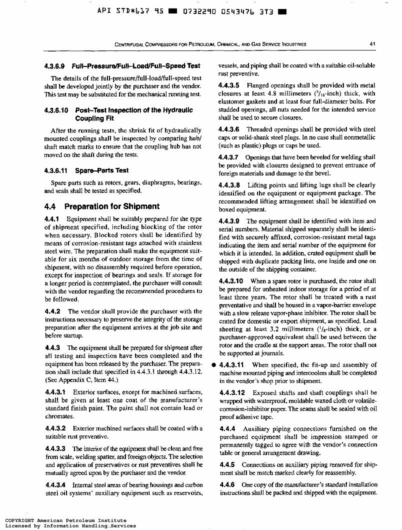
A P I STD*b17 95 0732290 0543476 3T3 W
CENTRIFUGAL COMPRESSORS FOR PETROLEUM, CHEMICAL, ANO GAS SERVICE INDUSTRIES 41
4.3.6.9 Full-Pressure/FulJ-LoadFulJ-Speed Test
The details of the full-pressure/full-load/full-speed test shall be developed jointly by the purchaser and the vendor. This test may be substituted for the mechanical running test.
4.3.6.10 Post-Test Inspection of the Hydraulic Coupling Fit
After the running tests, the shrink fit of hydraulically mounted couplings shall be inspected by comparing hub/ shaft match marks to ensure that the coupling hub has not moved on the shaft during the tests.
4.3.6.11 Spare-Parts Test
and seals shall be tested as specified. Spare parts such as rotors, gears, diaphragms, bearings,
4.4 Preparation for Shipment 4.4.1 Equipment shall be suitably prepared for the type of shipment specified, including blocking of the rotor when necessary. Blocked rotors shall be identified by means of corrosion-resistant tags attached with stainless steel wire. The preparation shall make the equipment suit- able for six months of outdoor storage from the time of shipment, with no disassembly required before operation, except for inspection of bearings and seals. If storage for a longer period is contemplated, the purchaser will consult with the vendor regarding the recommended procedures to be followed.
4.4.2 The vendor shall provide the purchaser with the instructions necessary to preserve the integrity of the storage preparation after the equipment arrives at the job site and before startup.
4.4.3 The equipment shall be prepared for shipment after all testing and inspection have been completed and the equipment has been released by the purchaser. The prepara- tion shall include that specified in 4.4.3.1 through 4.4.3.12. (See Appendix C, Item 44.)
4.4.3.1 Exterior surfaces, except for machined surfaces, shall be given at least one coat of the manufacturer’s standard finish paint. The paint shall not contain lead or chromates.
4.4.3.2 suitable rust preventive.
4.4.3.3 The interior of the equipment shall be clean and free from scale, welding spatter, and foreign objects. The selection and application of preservatives or rust preventives shall be mutually agreed upon by the purchaser and the vendor.
4.4.3.4 Internal steel areas of bearing housings and carbon steel oil systems’ auxiliary equipment such as reservoirs,
Exterior machined surfaces shall be coated with a
O
vessels, and piping shall be coated with a suitable oil-soluble rust preventive.
4.4.3.5 Flanged openings shall be provided with metal closures at least 4.8 millimeters (3/i6-inch) thick, with elastomer gaskets and at least four full-diameter bolts. For studded openings, all nuts needed for the intended service shall be used to secure closures.
4.4.3.6 Threaded openings shall be provided with steel caps or solid-shank steel plugs. In no case shall nonmetallic (such as plastic) plugs or caps be used.
4.4.3.7 Openings that have been beveled for welding shall be provided with closures designed to prevent entrance of foreign materials and damage to the bevel.
4.4.3.8 Lifting points and lifting lugs shall be clearly identified on the equipment or equipment package. The recommended lifting arrangement shall be identified on boxed equipment.
4.4.3.9 The equipment shall be identified with item and serial numbers. Material shipped separately shall be identi- fied with securely affixed, corrosion-resistant metal tags indicating the item and serial number of the equipment for which it is intended. In addition, crated equipment shall be shipped with duplicate packing lists, one inside and one on the outside of the shipping container.
4.4.3.1 O When a spare rotor is purchased, the rotor shall be prepared for unheated indoor storage for a period of at least three years. The rotor shall be treated with a rust preventative and shall be housed in a vapor-barrier envelope with a slow release vapor-phase inhibitor. The rotor shall be crated for domestic or export shipment, as specified. Lead sheeting at least 3.2 millimeters (‘/*-inch) thick, or a purchaser-approved equivalent shall be used between the rotor and the cradle at the support areas. The rotor shall not be supported at journals.
4.4.3.11 When specified, the fit-up and assembly of machine mounted piping and intercoolers shall be completed in the vendor’s shop prior to shipment.
4.4.3.12 Exposed shafts and shaft couplings shall be wrapped with waterproof, moldable waxed cloth or volatile- corrosion-inhibitor paper. The seams shall be sealed with oil proof adhesive tape.
4.4.4 Auxiliary piping connections furnished on the purchased equipment shall be impression stamped or permanently tagged to agree with the vendor’s connection table or general arrangement drawing.
4.4.5 Connections on auxiliary piping removed for ship- ment shall be match marked clearly for reassembly,
4.4.6 One copy of the manufacturer’s standard installation instructions shall be packed and shipped with the equipment.
COPYRIGHT American Petroleum InstituteLicensed by Information Handling ServicesCOPYRIGHT American Petroleum InstituteLicensed by Information Handling Services
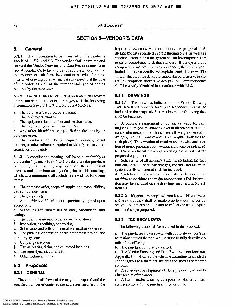
~
A P I STDSbL7 95 a 0732290 0543477 23T
42 API STANDARD 617
SECTION 5-VENDOR’S DATA
5.1 General 5.1.1 The information to be furnished by the vendor is specified in 5.2. and 5.3. The vendor shall complete and forward the Vendor Drawing and Data Requirements form (see Appendix C), to the address or addresses noted on the inquiry or order. This form shall detail the schedule for trans- mission of drawings, curves, and data as agreed to at the time of the order, as well as the number and type of copies required by the purchaser.
5.1.2 The data shall be identified on transmittal (cover) letters and in title blocks or title pages with the following information(see5.2.1,5.3.1.1,5.3.5,and5.3.6.1):
a. The purchaserluser’s corporate name. b. The job/project number. c. The equipment item number and service name. d. The inquiry or purchase order number. e. Any other identification specified in the inquiry or purchase order. f. The vendor’s identifying proposal number, serial number, or other reference required to identify return corre- spondence completely.
5.1.3 A coordination meeting shall be held, preferably at the vendor’s plant, within 4 to 6 weeks after the purchase commitment. Unless otherwise specified, the vendor will prepare and distribute an agenda prior to this meeting, which, as a minimum shall include review of the following items:
a. The purchase order, scope of supply, unit responsibility, and sub-vendor items. b. The data sheets. c. Applicable specifications and previously agreed upon exceptions. d. Schedules for transmittal of data, production, and testing. e. The quality assurance program and procedures. f. Inspection, expediting, and testing. g. Schematics and bills of material for auxiliary systems. h. The physical orientation of the equipment piping, and auxiliary systems. i. Coupling selections. j. k. The rotor dynamics analysis. I. Other technical items.
Thrust-bearing sizing and estimated loadings.
5.2 Proposals 5.2.1 GENERAL
The vendor shall forward the original proposal and the specified number of copies to the addresses specified in the
inquiry documents. As a minimum, the proposal shall include the data specified in 5.2.2 through 5.2.4, as well as a specific statement that the system and all its components are in strict accordance with this standard. If the system and components are not in strict accordance, the vendor shall include a list that details and explains each deviation. The vendor shall provide details to enable the purchaser to evalu- ate any proposed alternative designs. All correspondence shall be clearly identified in accordance with 5.1.2.
5.2.2 DRAWINGS
5.2.2.1 The drawings indicated on the Vendor Drawing and Data Requirements form (see Appendix C) shall be included in the proposal. As a minimum, the following data shall be furnished:
a. A general arrangement or outline drawing for each major skid or system, showing overall dimensions, mainte- nance clearance dimensions, overall weights, erection weights, and maximum maintenance weights (indicated for each piece). The direction of rotation and the size and loca- tion of major purchaser connections shall also be indicated. b. Cross-sectional drawings showing the details of the proposed equipment. c. Schematics of all auxiliary systems, including the fuel, lube-oil, seal-oil, or self-acting gas, control, and electrical systems. Bills of material shall be included. d. Sketches that show methods of lifting the assembled machine or machines and major components. (This informa- tion may be included on the drawings specified in 5.2.2. l , Item a.)
5.2.2.2 If typical drawings, schematics, and bills of mate- rial are used, they shall be marked up to show the correct weight and dimension data and to reflect the actual equip- ment and scope proposed.
5.2.3 TECHNICAL DATA
The following data shall be included in the proposal:
a. The purchaser’s data sheets, with complete vendor’s in- formation entered thereon and literature to fully describe de- tails of the offering. b. The purchaser’s noise data sheet. c. The Vendor Drawing and Data Requirements form (see Appendix C), indicating the schedule according to which the vendor agrees to transmit all the data specified as part of the contract. d. A schedule for shipment of the equipment, in weeks after receipt of the order. e. A list of major wearing components, showing inter- changeability with the purchaser’s other units.
COPYRIGHT American Petroleum InstituteLicensed by Information Handling ServicesCOPYRIGHT American Petroleum InstituteLicensed by Information Handling Services
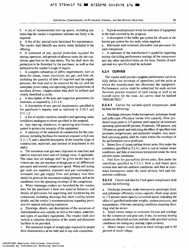
API STD*:bL7 95 0732290 0543478 1 7 6
CENTRIFUGAL COMPRESSORS FOR PETROLEUM, CHEMICAL, AND GAS SERVICE INDUSTRIES 43
f. A list of recommended start-up spares, including any items that the vendor’s experience indicates are likely to be required. g. A list of the special tools furnished for maintenance. The vendor shall identify any metric items included in the offering. h. A statement of any special protection required for startup, operation, and periods of idleness under the site con- ditions specified on the data sheets. The list shall show the protection to be furnished by the purchaser, as well as that included in the vendor’s scope of supply. i. A complete tabulation of utility requirements, such as those for steam, water, electricity, air, gas, and lube oil, including the quantity of lube oil required and the supply pressure, the heat load to be removed by the oil, and the nameplate power rating and operating power requirements of auxiliary drivers. (Approximate data shall be defined and clearly identified as such). j. A description of the tests and inspection procedures for materials, as required by 2.1 1.1.4. k. A description of any special requirements specified in the purchaser’s inquiry and as outlined in 2.10.3 and 2.11.1.2. 1. A list of similar machines installed and operating under conditions analogous to those specified in the proposal. m. Any start-up, shutdown, or operating restrictions re- quired to protect the integrity of the equipment. n. A summary of the materials of construction for the com- pressor, including hardness for materials exposed to H,S (see 2.11.1.7) and a detailed description of the impeller (type of construction, materials, and method of attachment to the shaft). o. The maximum seal-gas rates (injection or eduction) and rated or expected inner seal-oil leakage rates, if applicable. The inner seal oil leakage shall be given on the basis of volume per day per machine at design gas or oil differential pressures and normal compressor speed. When self-acting gas seals are supplied, expected seal gas consumption, minimum seal gas supply flow, and primary vent flow should be given at the maximum sealing pressure, and at the conditions over the operating envelope of the compressor. p. When interstage coolers are furnished by the vendor, data for the purchaser’s heat and material balances and details of provisions for separating and withdrawing the condensate, including drawings that show cooling system details, and the vendor’s recommendations regarding provi- sion for support and piping expansion. q. Drawings, details, and descriptions of the operations of instrumentation and controls, as well as the makes, materials, and types of auxiliary equipment. The vendor shall also include a complete description of the alarm and shutdown facilities to be provided. r. The minimum length of straight pipe required for proper flow characteristics at the inlet and at any side connection.
s. Typical sound pressure levels for each item of equipment in the train covered by the proposal. t. A description of the buffer gas system for oil seals or the barrier gas system for dry seals, when required. u. Maximum and minimum allowable seal pressures for each compressor. v. A statement of the manufacturer’s capability regarding testing (including performance testing) of the compressor and any other specified items on the train. Details of each optional test specified shall be included.
5.2.4 CURVES
The vendor shall provide complete performance curves to fully define the envelope of operations and the point at which the manufacturer has illustrated the equipment. Performance curves shall be submitted for each section (between process nozzles) of each casing as well as an overall curve for the train. All curves shall be marked “PREDICTED.”
5.2.4.1 Curves for variable-speed compressors shall include the following:
a. Discharge pressure; brake horsepower; polytropic head and porytropic efficiency versus inlet capacity (from pre- dicted surge point to 115 percent rated capacity) at minimum operating speed and 80 percent, 90 percent, 100 percent, and 105 percent speed, and indicating the effect of specified inlet pressures, temperatures, and molecular weights. Any speci- fied operating points shall be noted within the envelope of the performance curve predicted. b. Steam flow of steam-turbine driven units, first under the conditions specified in 5.2.4.1, Item a, and at normal steam conditions, and then at maximum horsepower under the most adverse steam conditions. c. Fuel flow for gas-turbine driven units, first under the conditions specified in 5.2.4.1, Item a, and based upon normal fuel and site-ambient conditions, and then at maxi- mum horsepower under the most adverse fuel and site- ambient conditions.
5.2.4.2 Curves and data for fixed speed compressors shall include the following:
a. Discharge pressure; brake horsepower; polytropic head; and polytropic efficiency versus capacity (from surge point to 115 percent rated capacity) at normal speed, indicating the effect of specified molecular weights, suction pressures, and temperatures. Alternate operating conditions requiring throt- tling shall be shown. b. Speed versus torque to overcome friction and windage for the compressor and gear unit, if any, for normal starting conditions (throttled suction) and also with specified suction conditions for emergency starting (open suction). c. Motor torque versus speed at rated voltage and at 80 percent of rated voltage.
COPYRIGHT American Petroleum InstituteLicensed by Information Handling ServicesCOPYRIGHT American Petroleum InstituteLicensed by Information Handling Services
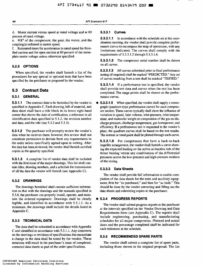
A P I STDUbL7 95 0732290 0543479 002
44 API STANDARD 617
d. Motor current versus speed at rated voltage and at 80 percent of rated voltage. e. W P of the compressor, the gear, the motor, and the coupling(s) referred to motor speed. f. Estimated times for acceleration to rated speed for throt- tled suction and for open suction at 80 percent of the name- plate motor voltage unless otherwise specified.
5.2.5 OPTIONS
When specified, the vendor shall furnish a list of the procedures for any special or optional tests that have been specified by the purchaser or proposed by the vendor.
5.3 Contract Data 5.3.1 GENERAL
5.3.1.1 The contract data to be furnished by the vendor is specified in Appendix C . Each drawing, bill of material, and data sheet shall have a title block in its lower right-hand comer that shows the date of certification, a reference to ali identification data specified in 5.1.2, the revision number and date, and the title (see 5.3.2 and 5.3.3).
5.3.1.2 The purchaser will promptly review the vendor’s data when he receives them; however, this review shall not constitute permission to deviate from any requirements in the order unless specifically agreed upon in writing. After the data has been reviewed, the vendor shall furnish certified copies in the quantity specified.
5.3.1.3 A complete list of vendor data shall be included with the first issue of the major drawings. This list shall con- tain titles, drawing numbers, and a schedule for transmission of all the data the vendor will furnish (see Appendix C).
5.3.2 DRAWINGS
The drawings furnished shall contain sufficient informa- tion so that with the drawings and the manuals specified in 5.3.6, the purchaser can properly install, operate, and main- tain the ordered equipment. Drawings shall be clearly legible, and identified in accordance with 5.3.1.1. As a minimum, the drawings shall include the details listed in Appendix C.
5.3.3 TECHNICAL DATA
The data shall be submitted in accordance with Appendix C and identified in accordance with 5.3.1.1. Any comments on the drawings or revisions of specifications that necessitate a change in the data shall be noted by the vendor. These notations will result in the purchaser’s issue of completed, corrected data sheets as part of the order specifications.
5.3.3.1 Curves
5.3.3.1.1 In accordance with the schedule set at the coor- dination meeting, the vendor shall provide complete perfor- mance curves to encompass the map of operations, with any limitations indicated. The curves shall comply with the requirements of 5.3.3.1.2 through 5.3.3.1.6.
5.3.3.1.2 The compressor serial number shall be shown on all curves.
5.3.3.1.3 All curves submitted prior to final performance testing (if required) shall be marked “PREDICTED.” Any set of curves resulting from a test shall be marked “TESTED.”
5.3.3.1.4 If a performance test is specified, the vendor shall provide test data and curves when the test has been completed. The surge points shall be shown on the perfor- mance curves.
When specified, the vendor shall supply a nomo- graph (quadrant-type performance curve) for each compres- sor section. These curves typically shall show the influence of variation in speed, inlet volume, inlet pressure, inlet temper- ature, and molecular weight or composition of the gas on dis- charge pressure, discharge temperature, gas horsepower, and efficiency. If a performance test is requested in the vendor’s plant, the quadrant curves shall be based on the test results. The normal or rated point shall be plotted through each curve.
5.3.3.1.6 For compressors that have a back-to-back impeller arrangement, the vendor shall furnish a curve show- ing the expected loading on the active or inactive side of the thrust bearing versus any combination of the differential pressures across the low-pressure and high-pressure sections of the casing.
O 5.3.3.1.5
5.3.3.2 Data Sheets
The vendor shall provide full information to enable com- pletion of the data sheets for the train and auxiliary equip- ment, first for “as purchased,” and then for “as built.” This should be done by the vendor correcting and filling out the data sheets and submitting copies to the purchaser.
0 5.3.4 PROGRESS REPORTS
The vendor shall submit progress reports to the purchaser at the intervals specified on the Vendor Drawing and Data Requirements form (see Appendix C). The reports shall include engineering, purchasing, and manufacturing schedules for all major components. Planned and actual dates and the percentage completed shall be indicated for each milestone in the schedule.
5.3.5 RECOMMENDED SPARE PARTS
The vendor shall submit a complete list of spare parts, including those shown in the original proposal. The list
COPYRIGHT American Petroleum InstituteLicensed by Information Handling ServicesCOPYRIGHT American Petroleum InstituteLicensed by Information Handling Services
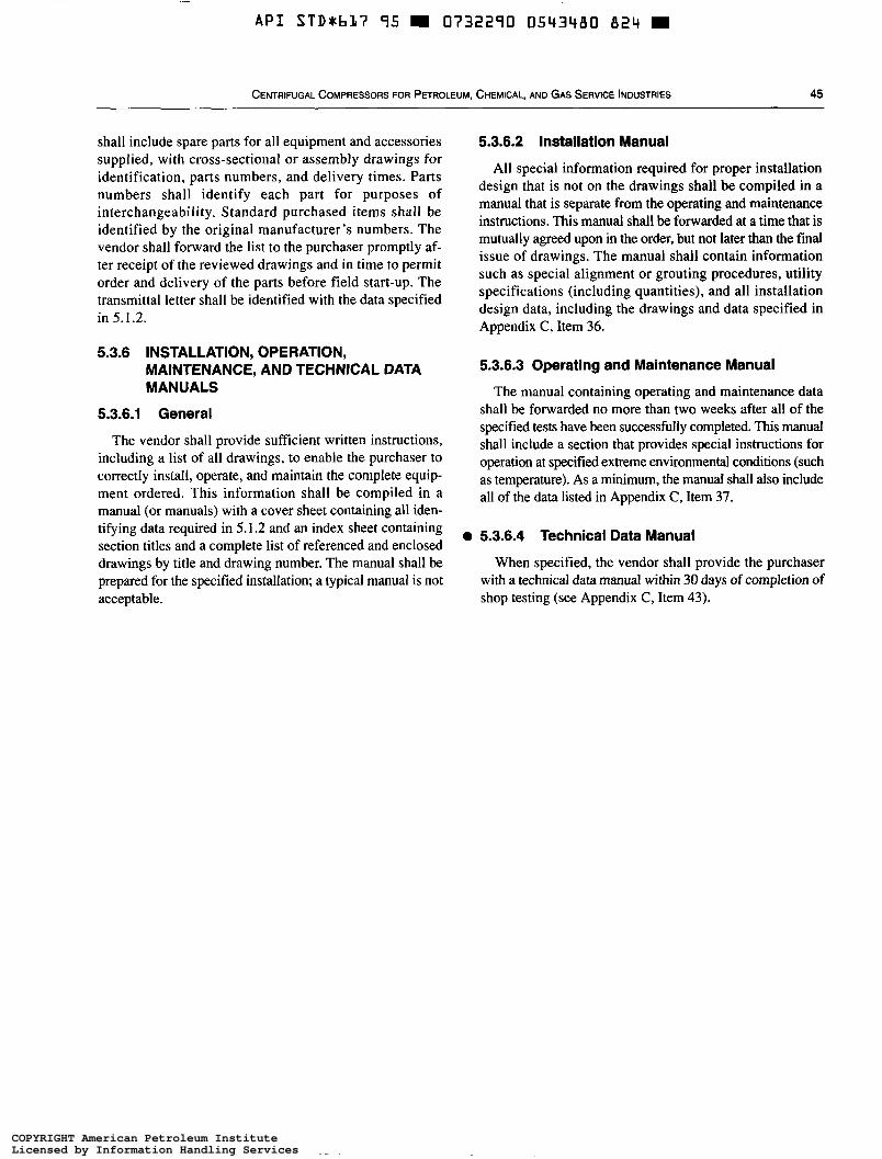
A P I STD+b17 95 0732290 0543480 824
CENTRIFUGAL COMPRESSORS FOR PETROLEUM, CHEMICAL, AND GAS SERVICE INDUSTRIES 45
shall include spare parts for all equipment and accessories supplied, with cross-sectional or assembly drawings for identification, parts numbers, and delivery times. Parts numbers shall identify each part for purposes of interchangeability. Standard purchased items shall be identified by the original manufacturer’s numbers. The vendor shall forward the list to the purchaser promptly af- ter receipt of the reviewed drawings and in time to permit order and delivery of the parts before field start-up. The transmittal letter shall be identified with the data specified in 5.1.2.
5.3.6 INSTALLATION, OPERATION, MAINTENANCE, AND TECHNICAL DATA MANUALS
5.3.6.1 General
The vendor shall provide sufficient written instructions, including a list of all drawings, to enable the purchaser to correctly install, operate, and maintain the complete equip- ment ordered. This information shall be compiled in a manual (or manuals) with a cover sheet containing all iden- tifying data required in 5.1.2 and an index sheet containing section titles and a complete list of referenced and enclosed drawings by title and drawing number. The manual shall be prepared for the specified installation; a typical manual is not acceptable.
5.3.6.2 Installation Manual
All special information required for proper installation design that is not on the drawings shall be compiled in a manual that is separate from the operating and maintenance instructions. This manual shall be forwarded at a time that is mutually agreed upon in the order, but not later than the final issue of drawings. The manual shall contain information such as special alignment or grouting procedures, utility specifications (including quantities), and all installation design data, including the drawings and data specified in Appendix C, Item 36.
5.3.6.3 Operating and Maintenance Manual
The manual containing operating and maintenance data shall be forwarded no more than two weeks after ali of the specified tests have been successfully completed. This manual shall include a section that provides special instructions for operation at specified extreme environmental conditions (such as temperature). As a minimum, the manual shall also include all of the data listed in Appendix C, Item 37.
o 5.3.6.4 Technical Data Manual
When specified, the vendor shall provide the purchaser with a technical data manual within 30 days of completion of shop testing (see Appendix C, Item 43).
COPYRIGHT American Petroleum InstituteLicensed by Information Handling ServicesCOPYRIGHT American Petroleum InstituteLicensed by Information Handling Services
~ ~
A P I STDxbL7 95 0732290 0543483 7b0
APPENDIX A-TYPICAL DATA SHEETS
47
COPYRIGHT American Petroleum InstituteLicensed by Information Handling ServicesCOPYRIGHT American Petroleum InstituteLicensed by Information Handling Services
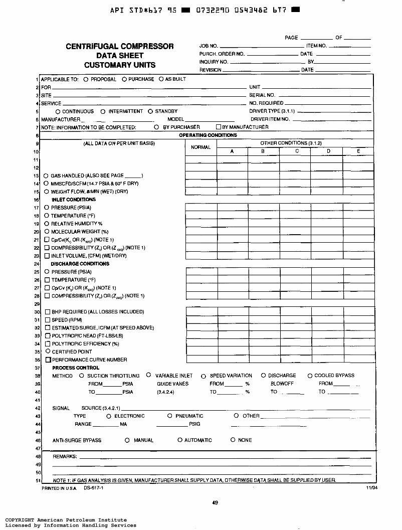
A P I STD*bL7 95 0732270 0543482 bT7 =
CENTRIFUGAL COMPRESSOR DATA SHEET
PAGE OF
JOB NO. ITEM NO.
PURCH. ORDER NO. DATE
INQUIRY NO. BY
REVISKIN DATE CUSTOMARY UNITS
i I APPLICABLE TO: o PROPOSAL o PURCHASE O AS BUILT I I 21 FOR UNIT
3 SITE SERIAL NO.
4 SERVICE NO. REQUIRED
5 0 CONTINUOUS 0 INTERMITTENT O STANDBY DRIVERTYPE (3.1.1)
6 MANUFACTURER MODEL DRIVER ITEM NO.
7 NOTE: INFORMATION TO BE COMPLETED: 0 BY PURCHASER O B Y MANUFACTURER
8 OPERATING CONDITIONS 9 (ALL DATA ON PER UNIT BASIS) OTHER CONDITIONS (3.1.2)
10 A I B I C I D E NORMAL
11
12 13 0 GAS HANDLED (ALSO SEE PAGE )
14
15
16 INLET CONDITIONS 17 0 PRESSURE(PS1A)
18 0 TEMPERATURE (OF) 19 0 RELATIVE HUMIDITY %
20 0 MOLECULAR WEIGHT (%)
21 0 Cp/Cv(K,) OR (KAvJ (NOTE 1)
22 0 COMPRESSIBILITY (Z,) OR (ZAvG) (NOTE 1)
23 0 INLETVOLUME, (CFM) (WETIDRY)
24 DISCHARGE CONDITIONS 25 0 PRECSURE(PSIA)
26 0 TEMPERATURE ("F)
27 0 CplCv (4) OR (KA& (NOTE 1) 28 0 COMPRESSIBILITY (ZJ OR (Z& (NOTE 1)
0 MMSCFD/SCFM(14.7 PSIA &60" F DRY)
O WEIGHT FLOW,#/MIN (WET) (DRY)
I I I t I I 29 30
31 0 SPEED (RPM) 32
33 0 POLYTROPIC HEAD (FT-LBLB)
34 0 POLYTROPIC EFFICIENCY (%)
35 0 CERTIFIED POINT
36 PERFORMANCE CURVE NUMBER
37 PROCESS CONTROL 38 METHOD 0 SUCTION THROTTLING 0 VARIABLE INLET 0 SPEED VARIATION 0 DISCHARGE 0 COOLED BYPASS 39 FROM PSIA GUIDE VANES FROM % BLOWOFF FROM
40 TO PSIA (3.4.2.4) TO % TO TO
41
42 SIGNAL SOURCE (3.4.2.1) 43 TYPE 0 ELECTRONIC 0 PNEUMATIC 0 OTHER 44 RANGE MA PSIG
45
46 ANTI-SURGE BYPASS 0 MANUAL 0 AUTOMATIC 0 NONE
[7 BHP REQUIRED (ALL LOSSES INCLUDED)
0 ESTIMATED SURGE, ICFM (AT SPEED ABOVE)
481 REMARKS:
50
51 NOTE 1: IF GAS ANALYSIS IS GIVEN, MANUFACTURER SHALL SUPPLY DATA, OTHERWISE DATA SHALL BE SUPPLIED BY USER. 11/94 PRINTED IN U S A OS-617-1
49
COPYRIGHT American Petroleum InstituteLicensed by Information Handling ServicesCOPYRIGHT American Petroleum InstituteLicensed by Information Handling Services
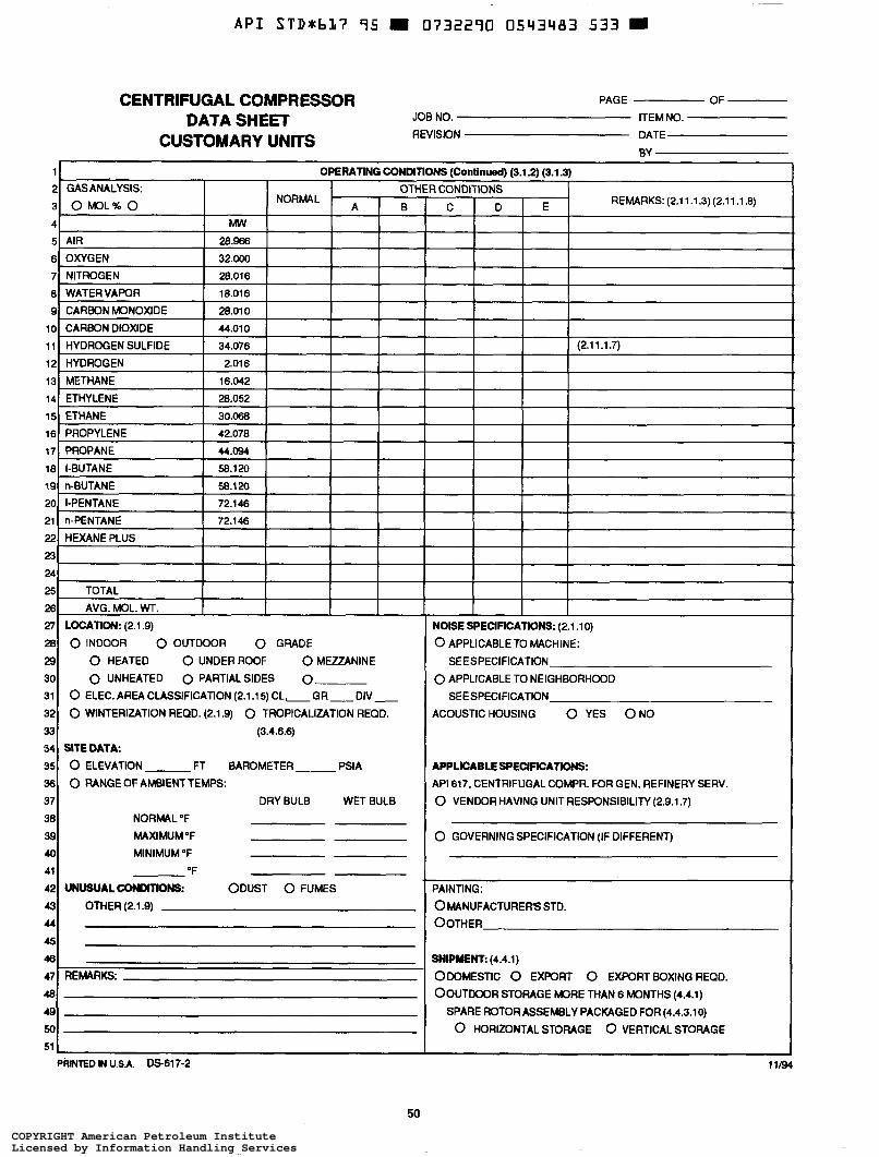
A P I STD*bL7 75 H 0732270 05Y3Y83 533
CENTRIFUGAL COMPRESSOR DATA SHEET
CUSTOMARY UNITS
PAGE OF JOB NO. ITEM NO.
REVISION DATE
1
2 GASANALYSIS: OTHER CONDITIONS
3 O M O L % O A I
OPERATING CONDITIONS (Continued) (3.1 2) (3.1 3)
R NORMAL
4 MW 5 AIR 28.966 6 OXYGEN 32.000 7 NITROGEN 28.016 ai WATERVAWR I 18.016 I I I 9 CARBON MONOXIDE 28.01 o io CARBON DIOXIDE 44.01 o 1 1 HYDROGEN SULFIDE 34.076 12 HYDROGEN 2.016 13 METHANE 16.042 14 ETHYLENE 28.052 15 ETHANE 30.068 16 PROPYLENE 42.070 i? PROPANE 44.094
181 I-BUTANE I 58.120 I I I i9 n-BUTANE 58.120 20 I-PENTANE 72.146 21 n-PENTANE 72.146 221 HEXANE PLUS I I I I 23 24 25 TOTAL
26 AVG.MOL.WT. I 27 LOCATION: (2.1.9) 28 0 INDOOR 0 OUTDOOR 0 GRADE
29 O HEATED O UNDER ROOF 0 MEZZANINE
30 0 UNHEATED 0 PARTIALSIDES 0 31 32 0 WINTERIZATION REQD. (2.1.9) 0 TROPICALIZATION REQD.
33 (3.4.6.6) 34 SITEDATA. 35 0 ELEVATION FT BAROMETER PSIA
36 37 DRY BULB WET BULB 38 NORMAL "F
39 MAXIMUMOF
40 MINIMUM "F
41 "F 42 UNUSUALCONûITWJS: ODUST 0 FUMES
43 OTHER (2.1.9) 44
45 46
47 REMARKS:
0 ELEC. AREA CLASSIFICATION (2.1.1 5) CL.- GR- DIV-
O RANGE OF AMBENT TEMPS:
50
REMARKS(2.11.1.3)(2.11.1.8) C D E
I I I
(2.1 1.1.7)
I I I
NOISE SPECIFICATIONS: (2.1 .lo) 0 APPLICABLETO MACHINE:
0 APPLICABLE TO NEIGHBORHOOD
ACOUSTICHOUSING O YES O N 0
SEE SPECIFICATION
SEE SPEC1 FICATION
APPLICABLE SPECIFICATIONS: API 617, CENTRIFUGAL COMPR. FOR GEN. REFINERY SERV.
0 VENDOR HAVING UNIT RESPONSIBILITY (2.9.1.7)
0 GOVERNING SPECIFICATION (IF DIFFERENT)
PAINTING:
OMANUFACTURERS STD.
OOTHER
%IPMNE (4.4.1) ODOMESTIC 0 EXPORT 0 EXPORT BOXING REQD.
OOUTOOOR STORAGE MORE THAN 6 MONTHS (4.4.1) SPARE ROTOR ASSEMBLY PACKAGED FOR (4.4.3.10) 0 HORIZONTAL STORAGE 0 VERTICAL STORAGE
i I
11/94 PRtNTED H U.SA. DS-617-2
50
COPYRIGHT American Petroleum InstituteLicensed by Information Handling ServicesCOPYRIGHT American Petroleum InstituteLicensed by Information Handling Services
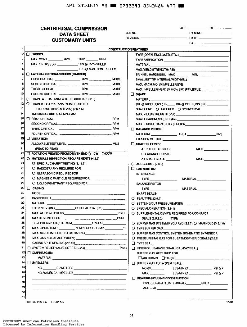
A P I S T D * b I ï 95 0732290 0543484 47T
1
2 3
4
5
6
7
8 9
10
11
12 13
14
15
16 17
18
19
20
21
CENTRIFUGAL COMPRESSOR PAGE OF
JOB NO. ITEM NO.
REVISION DATE DATA SHEET
CUSTOMARY UNITS BY
CONSTRUCT 0 SPEEDS:
MAX.CONT. RPM TRIP RPM
MAX. TIP SPEEDS: .- FPS Q 100% SPEED FPS @ MAX. CONT. SPEED
0 LATERAL CRITICAL SPEEDS (DAMPED) FIRSTCRITICAL RPM MODE
SECOND CRITICAL RPM MODE
THIRD CRITICAL RPM MODE
FOURTH CRITICAL RPM MODE
0 TRAIN LATERAL ANALYSIS REQUIRED (2.9.2.3) 0 TRAIN TORSIONAL ANALYSIS REQUIRED
(TURBINE DRIVEN TRAIN) (2.9.4.5)
TORSIONAL CRITICALSPEEDS: 0 FIRSTCRITICAL RPM
SECOND CRITICAJ RPM
THIRD CRITICAL RPM
FOURTH CRITICAL RPM
0 UBRATION: ALLOWABLE TEST LEVEL MILS
(PEAK TO PEAR 22
23
\ - ----, 0 ROTATION, VIEWED FROM DRIVEN E N D 0 CW OCCW 0 MATERIALS INSPECTION REQUIREMENTS (4.2.2)
24
25
26
27
28
29 30
32
31
33
34
35
36 37
38
39
40
42
41
43
44 45
46 47
48 49
50
51
3 FEATURES
TYPE (OPEN, ENCLOSED, ETC.)
TYPE FABRICATION MATERIAL
MAX.YIELDSTRENGTH (PSI)
BRINNEL HARDNESS: MAX MIN. SMALLESTTIP INTERNAL WIDTH (IN.)
MAX. MACH. NO. @ IMPELLER EYE
MAX. IMPELLER HEAD Q 100% SPD (FT-LBSLB)
0 SHAFT: MATERIAL DIA Q IMPELLERS (IN) - DIA @ COUPLING (IN.)
SHAFT END: 0 TAPERED 0 CYLINDRICAL
MAX. YIELDSTRENGTH (PSI)
SHAFT HARDNESS (BNH) (Rc) - MAXTORQUE CAPABILITY (FT-LBS)
0 BALANCE PISTON:
MATERIAL AREA (IN2) FIXATION METHOD
0 SHAFT SLEEVES : AT INTERSTG. CLOSE MATL
CLEARANCE POINTS
AT SHAFT SEALS MATL
0 ACCESSIBLE (2.8.2) 0 LABYRINTHS
INTERSTAGE
TYPE MATERIAL
BALANCE PSITON TYPE MATERIAL
SHAFT SEALS 0 SEALTYPE:(2.8.3)
0 SETTLING OUT PRESSURE (PSIG)
0 SPECIALOPERATION (2.8.1)
0 SUPPLEMENTAL DEVICE REQUIRED FOR CONTACT
SEALS (2.8.3.2) TYPE
0 BUFFER GAS SYSTEM REQUIRED (2.8.7) 0 MANIFOLD (3.5.1.6)
0 TYPEBUFFERGAS
0 BUFFER GAS CONTROL SYSTEM SCHEMATIC BY VENDOR
0 PRESSURIZING GAS FOR SUBATMOSPHERIC SEALS (2.8.8) 0 TYPESEAL
0 INNEROIL LEAKAGE GUAR. (GAUDAYEEAL)
BUFFER GAS REQUIRED FOR:
0 BUFFER GAS FLOW(PER SEAL):
DAIR RUN-IN UITHER
NORM: LBSíMIN Q PSI A P
PSI A P MAX: LBSMIN Q
0 BEARING HOUSING CONSTRUCTION: TYPE (SEPARATE, INTERGRAL) SPLIT MATERIAL
11/94
il
0 SPECIALCHARPY TESTING (2.1 1.3)
0 RADIOGRAPHY REQUIRED FOR
0 ULTRASONIC REQUIRED FOR O MAGNETIC PARTICLE REQUIREDFOR
0 LIQUID PENETRANT REQUIRED FOR
0 CASING MODEL
MATERIAL CASING SPLIT
THICKNESS (IN.) CORR. ALLOW. (IN.)
MAX. WORKING PRESS PSIG
MAX DESIGN PRESS PSIG
TEST PRESS (PSIG): HELIUM HYDRO
MAX. OPER. TEMP. "F MIN. OPER. TEMP. OF
MAX. NO. OF IMPELLERS FOR CASING
MAX. CASING CAPACITY (ICFM)
CASING SPLITSEALING (2.2.1 o) 0 SYSTEM RELIEF VALVE SET PT. (2.2.4) PSIG
o DIAPHRAGMS: MATERIAL
0 IMPELLERS: NO. DIAMETERS
NO.VANESEA. IMPELLER
PRINTED IN U.S.A. DS-617-3
COPYRIGHT American Petroleum InstituteLicensed by Information Handling ServicesCOPYRIGHT American Petroleum InstituteLicensed by Information Handling Services
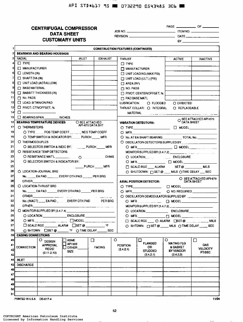
~
A P I STD+bL7 95 m 0732290 0543485 306
PAGE OF
JOB NO. ITEM NO.
REVISION DATE
CENTRIFUGAL COMPRESSOR DATA SHEET
CUSTOMARY UNITS BY
PAGE OF
ITEM NO.
DATE
BY ~ ~~
1 CONSTRUCTION FEATURES (CONTINUED) BEARINGS AND BEARING HOUSINGS
RADIAL INLET EXHAUST 0 TYPE
0 MANUFACTURER
0 LENGTH(IN)
0 SHAFT DIA (IN)
0 UNIT LOAD (ACTiALLOW)
0 BASEMATERIAL
0 BABBITTTHICKNESS(1N)
0 No.PADS
0 LOAD: BTWNiON PAD
0 PIVOT: CTWOFFSET. %
o [7 BEARING SPAN INCHES - ~
BEARING TEMPERATURE DEVICES O SEE ATTACHED API-670 DATA SHT 0 THERMISTORS
0 TYPE- POS TEMP COEFF NEG TEMP COEFF
0 TEMPSWITCH &INDICATOR BY:-PURCH-MFR
0 SELECTOR SWITCH & INDIC BY:
0 THERMOCOUPLES - PURCH - MFR
0 RESISTANCE TEMP DETECTORS
0 RESISTANCE MAT'L O OHMS
0 SELECTOR SWITCH & INDICATOR BY:
- PURCH - MFR
0 LOCATION-JOURNAL BRG No. - EA PAD EVERY OTH PAD- PER BRG
OTHER
0 LOCATION-THRUST BRG
No. EA PAD EVERY OTH PAD - PER BRG
OTHER
No. (INACT) - EA PAD - EVERY OTH PAD ~ PER BRG
0 MONITORSUPPLIED BY (3.4.7.4)
0 LOCATION ENCLOSURE
0 MFR. 0 MODEL
0 SHTDWN OSET @ "F OTIME DELAY SEC
0 SCALE RGE ALARM O S E T @ O F
CASING CONNECTIONS
THRUST ACTIVE INACTIVE- 0 TYPE
MANUFACTURER
0 UNIT LOADING (MAX PSI)
0 UNIT LOAD (ULT.) (PSI)
0 AREA(IN2) 0 NO.PADS
0 PIVOT: CENTEWOFFSET, %
0 PAD BASE MATL LUBRICATION: 0 FLOODED 0 DIRECTED
THRUST COLLAR: 0 INTEGRAL 0 REPLACEABLE
MATERIAL
0 SEEATTACHEDAPI-670 VIBRATION DETECTORS: DATASHEET
0 TYPE 0 MODEL
0 MFR
0 No. AT EA SHAFT BEARING TOTAL No.
0 OSCILLATOR-DETECTORSSUPPLIED BY
0 MFR 0 MODEL
MONITORSUPPLIED BY (3.4.7.2)
0 LOCATION ENCLOSURE
0 MFR. 0 MODEL
0 SCALE RGE -ALARM SET @ MILS
0 SHUTDOWN: 0 SET @ - MILS OTIME DELAY -SEC
O SEE ATTACHED APIB7O AXIAL POSITION DETECTOR: DATA SHEET
0 TYPE 0 MODEL
0 MFR 0 NO. REQUIRED
0 OSCILLATOR-DEMODULATOR SUPPLIED BY
O MFR 0 MODEL MONITORSUPPLIED BY (3.4.7.2)
0 LOCATION ENCLOSURE
0 MFR. 0 MODEL
0 SCALE RGE - 0 ALARM E E T @ MILS 0 SHTDWN: 0 SET @ MILS OTIME DELAY -SEC
40
41
42
43
44
45
46
47
48 49
CONNECTION
50 I I I I I 51
PRINTED IN USA. OS-617-4 11/94
52 COPYRIGHT American Petroleum InstituteLicensed by Information Handling ServicesCOPYRIGHT American Petroleum InstituteLicensed by Information Handling Services
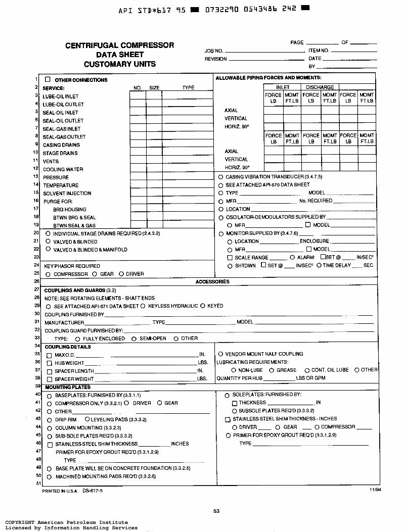
CENTRIFUGAL COMPRESSOR DATA SHEET
CUSTOMARY UNITS
43 44
45
46
47
48 49 50
PAGE OF
JOB NO. ITEM NO. REVISION DATE
BY
0 DRIP RIM 0 LEVELING PADS (3.3.3.2) 0 STAINLESS STEEL SHIM THICKNESS - INCHES
0 COLUMN MOUNTING (3.3.2.3)
0 SUB-SOLE PLATES REQ'D (3.3.3.2) 0 STAINLESSSTEELSHIMTHICKNESS INCHES TYPE
0 DRIVER- 0 GEAR- 0 COMPRESSOR - 0 PRIMER FOR EPOXY GROUT REQ'D (3.3.1.2.9)
PRIMER FOR EPOXY GROUT REQ'D (3.3.1.2.9)
TYPE
0 BASE PLATE WILL BE ON CONCRETE FOUNDATION (3.3.2.5)
0 MACHINED MOUNTING PADS REQ'D (3.3.2.6)
PRINTED IN U.S.A. DS-617-5 11/94
53
COPYRIGHT American Petroleum InstituteLicensed by Information Handling ServicesCOPYRIGHT American Petroleum InstituteLicensed by Information Handling Services
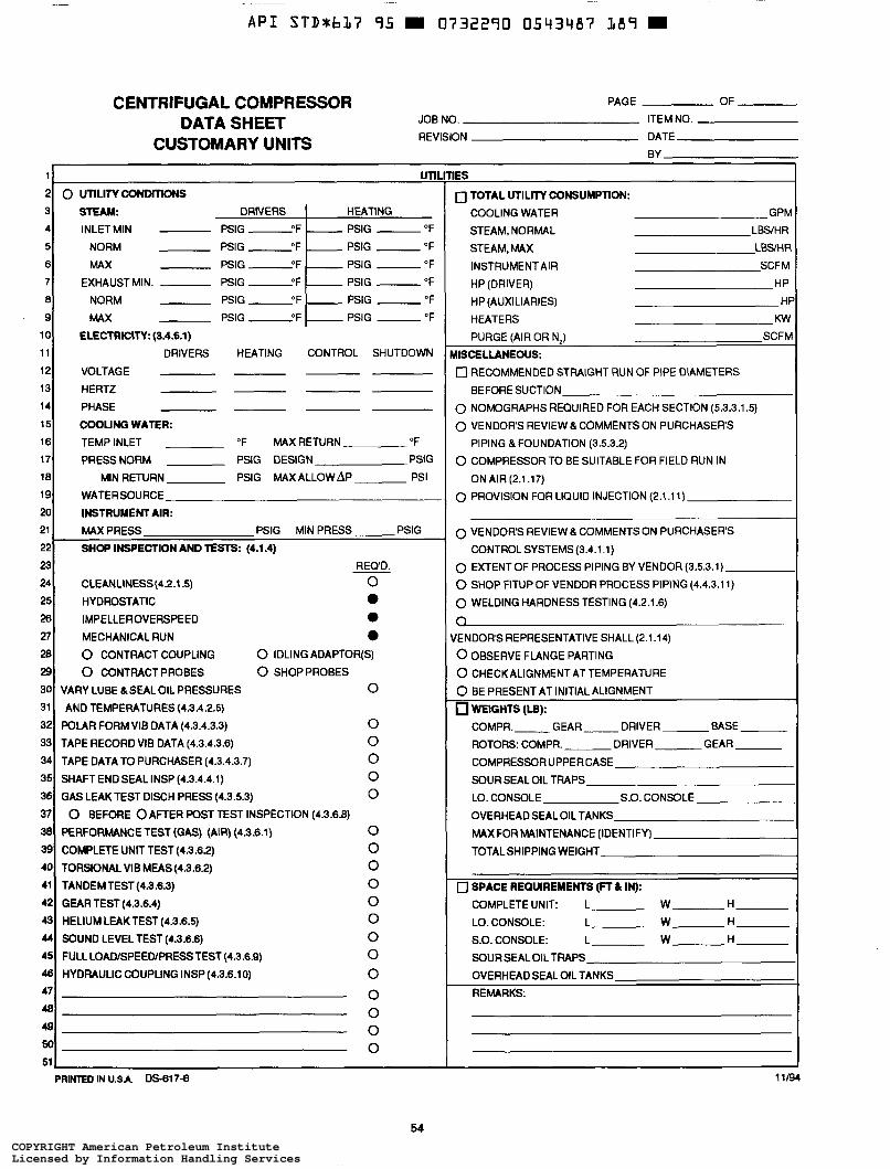
~ ~
A P I STDxbL7 95 0732290 0543487 LB9 =
1
2
CENTRIFUGAL COMPRESSOR PAGE OF
JOB NO. ITEM NO.
REVISION DATE DATA SHEET
CUSTOMARY UNITS BY
uni 0 UTiLITYCONMTIûNS
STEAM. DRIVERS INLETMIN - PSIG -OF
NORM - PSIG " F . MAX - P S I G " F
EXHAUST MIN. - PSIG L F
NORM - PSIG 2 F MAX - PSIG O F
3 4
5
6 7
8
9
10
11
12
13
14
15
16 17
18
19
HEATING - PSIG -OF
PSIG -"F
PSIG -OF
PSIG -"F
PSIG -OF
- PSIG - "F
20
21
22 MAXPRESS PSIG MIN PRESS PSIG
SHOP INSPECTION AND TESTS: (4.1.4)
23
24
25
26 27
28 29 30
31 32
33
34
35
36
37
38 39 40 41
42
43 44
45
48 47
48 49 50
1ES
0 TOTAL UTILITY CONSUMPTION: COOLING WATER GPM STEAM, NORMAL LBS/H R STEAM, MAX LBSúHR
INSTRUMENT AIR SCFM
HP (DRIVER) HP
HP (AUXILIARIES) HF
HEATERS Kw PURGE (AIR OR N,) SCFM
MISCELLANEOUS: 0 RECOMMENDED STRAIGHT RUN OF PIPE DIAMETERS
BEFORE SUCTION 0 NOMOGRAPHS REQUIRED FOR EACH SECTION (5.3.3.1.5)
0 VENDORS REVIEW & COMMENTSON PURCHASERS
PIPING &FOUNDATION (3.5.3.2)
O COMPRESSOR TO BE SUITABLE FOR FIELD RUN IN
ON AIR (2.1.17) 0 PROVISION FOR LIQUID INJECTION (2.1.1 i )
REQ'D.
CìEANCINESS(4.2.1.5) O HYDROSTATIC e IMPELLEROVERSPEED a MECHANICAL RUN e 0 CONTRACTCOUPLING 0 IDLINGADAPTOR(S)
0 CONTRACTPROBES 0 SHOPPROBES
VARY LUBE &SEALOIL PRESSURES O
POLAR FORM VIB DATA (4.3.4.3.3) O TAPE RECORD VIB DATA (4.3.4.3.6) O
SHAFT END SEAL INSP (4.3.4.4.1) O GAS LEAK TEST DISCH PRESS (4.3.5.3) O
PERFORMANCE TEST (GAS) (AIR) (4.3.6.1) O
AND TEMPERATURES (4.3.4.2.5)
TAPE DATATO PURCHASER(4.3.4.3.7) O
0 BEFORE 0 AFTER POST TEST INSPECTION (4.3.6.8)
COMPLETE UNIT TEST(4.3.6.2) O TORSIONAL VIE MEAS(4.3.6.2) O TANDEMTEST(4.3.6.3) O GEAR TEST (4.3.6.4) O HELIUMLEAKTEST (4.3.6.5) O SOUND LEVEL TEST (4.3.6.6) O FULL LOAOISPEEWPRESSTEST(4.3.6.8) O HYDRAULIC COUPLING INSP (4.3.6.10) O
O O O O
0 VENDOR'S REVIEW & COMMENTS ON PURCHASERS
0 EXTENT OF PROCESS PIPING BY VENDOR (3.5.3.1)
O SHOP FITUP OF VENDOR PROCESS PIPING (4.4.3.1 1)
0 WELDING HARDNESS TESTING (4.2.1.6)
CONTROL SYSTEMS (3.4.1 . i)
VENDOR'S REPRESENTATIVE SHALL (2.1.14)
0 OBSERVE FLANGE PARTING
0 CHECK ALIGNMENT AT TEMPERATURE
0 BE PRESENT AT INITIAL ALIGNMENT WEIGHTS (Lü): COMPR. GEAR- DRIVER BASE
ROTORS: COMPR. DRIVER GEAR
COMPRESSOR UPPERCASE
SOURSEAL OIL TRAPS LO. CONSOLE S.O. CONSOLE
OVERHEAD SEAL OIL TANKS
MAXFOR MAINTENANCE (IDENTIFY)
TOTALSHIPPING WEIGHT
~~
0 SPACE REQUIREMENTS (FT & IN):
COMPLETE UNIT: L W-H-
LO. CONSOLE: L- W-H-
S.O. CONSOLE: L- W-H- SOUR SEAL OIL TRAPS
11/94
OVERHEAD SEAL OIL TANKS REMARKS:
PRIMED IN USA. DS617-6
54 COPYRIGHT American Petroleum InstituteLicensed by Information Handling ServicesCOPYRIGHT American Petroleum InstituteLicensed by Information Handling Services
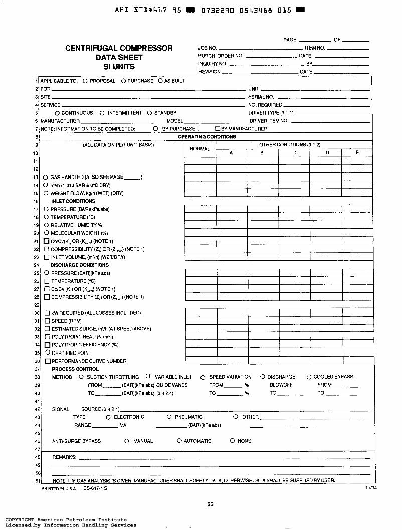
CENTRIFUGAL COMPRESSOR DATA SHEET
SI UNITS
1
2 3
4
5
6
PAGE OF
JOB NO. ITEM NO. PURCH. ORDER NO. DATE
INQUIRY NO. BY
REVISION DATE
APPLICABLE TO: 0 PROPOSAL 0 PURCHASE 0 AS BUILT
FOR UNIT
SITE SERIAL NO.
SERVICE NO. REQUIRED
0 CONTINUOUS 0 INTERMITTENT 0 STANDBY DRIVER TYPE (3.1.1) MANUFACTURER MODEL DRIVER ITEM NO.
7
8 NOTE: INFORMATION TO BE COMPLETED: 0 BY PURCHASER U B Y MANUFACTURER
OPERATING CONDITIONS
9
10 :;I 13 0 GAS HANDLED (ALSO SEE PAGE-
I
(ALL DATA ON PER UNIT BASIS) OTHER CONDITIONS (3.1.2) E
NORMAL A B C I D I
14 15
16
17 18
19
20
21
22
23
24 25
26
27
281 COMPRESSIBILITY (ZJ OR (ZAVG) (NOTE 1)
0 m3/h(1.013BARB0°C DRY)
0 WEIGHTFLOW. kgh (WET) (DRY)
0 PRESSURE (BAR)(kPaabs)
0 TEMPERATURE (OC) 0 RELATIVE HUMIDITY%
0 MOLECULAR WEIGHT (%)
Cp/Cv(K,, OR (K,,) (NOTE 1)
0 COMPRESSIBILITY (2,) OR (2 Ave) (NOTE 0 INLETVOLUME, (mYh) (WETIDRY)
DISCHARGE CONDITIONS 0 PRESSURE (BAR)(kPaabs) 0 TEMPERATURE ("C)
0 CVCv (\i OR
INLET CONDITIONS
(NOTE 1) I I I I I
I 29 30
31
32 33
34
35
36
37
38
39
40
41
42
43
44
45
46
47 48
49 50
51
0 kW REQUIRED (ALL LOSSES INCLUDED)
0 SPEED (RPM) 0 ESTIMATEDSURGE. m3/h (ATSPEED ABOVE)
0 POLYTROPIC HEAD (N-mlkg) POLYTROPIC EFFICIENCY (%)
0 CERTIFIED POINT PERFORMANCE CURVE NUMBER
PROCESS CONTROL METHOD 0 SUCTION THROTTLING 0 VARIABLE INLET 0 SPEED VARIATION 0 DISCHARGE 0 COOLED BYPASS
FROM (BAR)(kPa abc) GUIDE VANES FROM % BLOWOFF FROM
TO (BAR)(kPa abs) (3.4.2.4) TO % TO TO
SIGNAL SOURCE (3.4.2.1) TYPE 0 ELECTRONIC 0 PNEUMATIC 0 OTHER
RANGE MA (BAR)(kPa abc)
ANTI-SURGE BYPASS 0 MANUAL 0 AUTOMATIC 0 NONE
REMARKS:
NOTE 1: IF GAS ANALYSIS IS GIVEN, MANUFACTURER SHALL SUPPLY DATA. OTHERWISE DATA SHALL BE SUPPLIED BY USER. PRINTED IN U.S.A. DS-617-1 SI 11/94
55
COPYRIGHT American Petroleum InstituteLicensed by Information Handling ServicesCOPYRIGHT American Petroleum InstituteLicensed by Information Handling Services
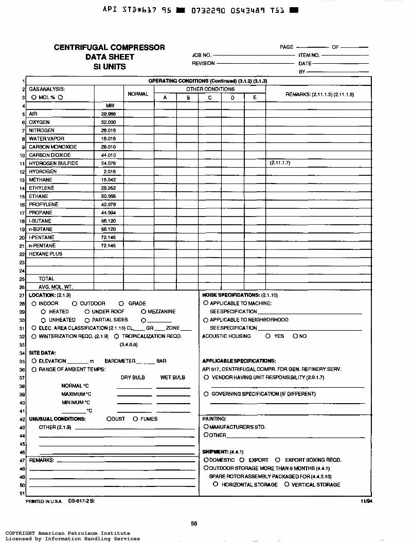
~
API STD*bL7 95 m 0732290 0543489 T5L =
24 25 26 27 28 29 30 31 32 33 34 35 36 37 38 39 40 41 42 43 44
45 46 47 48
CENTRIFUGAL COMPRESSOR DATA SHEET
SI UNITS
TOTAL
AVG.MOL.W. LOCATION: (2.1 9) 0 INDOOR 0 OUTDOOR 0 GRADE
0 HEATED O UNDER ROOF O MEZZANINE
0 UNHEATED 0 PARTIALSIDES 0 0 ELEC. AREA CLASSIFICATION (2.1.15) CL.-GR-ZONE-
0 WINTERIZATION REQD. (2.1.9) 0 TROPICALIZATION REQD.
(3.4.6.6) SITEDATA: O ELEVATION rn BAROMETER BAR 0 RANGEOFAMBIENTTEMPC:
DRY BULB WET BULB
NORMAL "C
MAXIMUM "C
MINIMUM "C
"C
UNUSUAL CONDITIONS ODUST O FUMES
OTHER (2.1.9)
REMARKS:
PAGE OF
JOB NO. ITEM NO.
REVISION DATE BY
11 OPERATING CONDIT 2 GASANALYSIS OTHI
3 O M O L % O B NORMAL A I
5 AIR 28.- 6 OXYGEN 32.000 7 NITROGEN 28.016 8 WATERVAPOR 18.016 9 CARBON MONOXIDE 28.010 io CARBON DIOXIDE 44.01 o 1 1 HYDROGEN SULFIDE 34.076 12 HYDROGEN I 13 METHANE I 16.042 I 14 ETHYLENE 28.052 I 151 ETHANE I I 16 PROPYLENE 42.078 17 PROPANE 44.094 18 I-BUTANE 58.1 20 191 n-BUTANE I 58.120 I I I 20 I-PENTANE 72.146 21 n-PENTANE 72.146
22 HEXANEPLUS
I
51
PRINTED IN USA. DS-617-2 SI
NS (Continued) (3.1.2) (3.1.3)
I CONDITIONS REMARKS: (2.1 1.1.3) (2.1 1.1 .8) C I E
(2.1 1.1.7)
NOISE SPECIFICATIONS (2.1 .lo) 0 APPLICABLE TO MACHINE:
SEE SPECIFICATION
0 APPLICABLE TO NEIGHBORHOOD
ACOUSTICHOUSING 0 YES O N 0
SEE SPECIFICATION
APPLICABLE SPECIFICATIONS: API 617. CENTRIFUGAL COMPR. FOR GEN. REFINERY SERV.
0 VENDOR HAVING UNIT RESPONSIBILITY (2.9.1.7)
0 GOVERNING SPECIFICATION (IF DIFFERENT)
PAINTING:
OMANUFACTURER'S STD. OOTHER
SHIPMENT: (4.4.1) ODOMESTIC 0 EXPORT O EXFORTBOXINGREQD.
OOUTWOR STORAGE MORE THAN 6 MONTHS (4.4.1) SPARE ROTOR ASSEMBLY PACKAGED FOR (4.4.3.10) 0 HORIZONTAL STORAGE 0 VERTICAL STORAGE
11/94
56 COPYRIGHT American Petroleum InstituteLicensed by Information Handling ServicesCOPYRIGHT American Petroleum InstituteLicensed by Information Handling Services
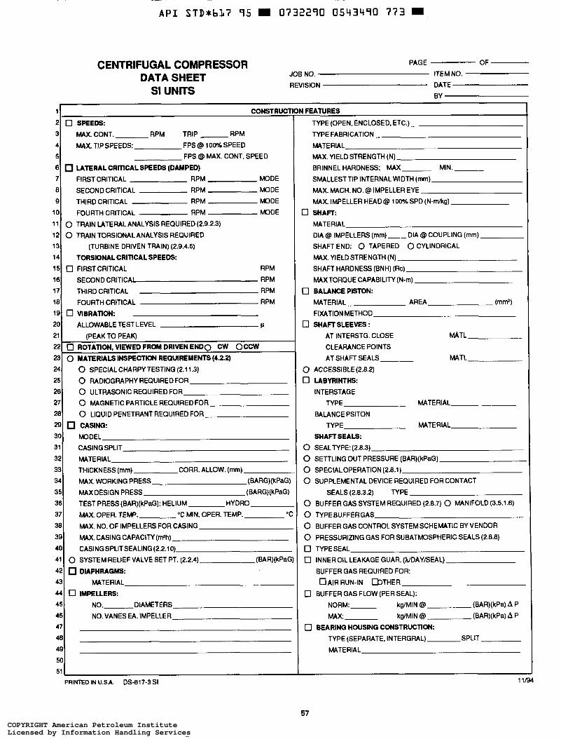
~-
A P I STDxbL7 95 D 0732290 0543490 773
2 3
4
5
6
7
8 9
10
11
12 13 14
15
16
17
18 19
20
PAGE OF
JOB NO. ITEM NO.
REVISION DATE
CENTRIFUGAL COMPRESSOR DATA SHEET
SI UNITS BY
0 SPEEDS MAX.CONT. RPM TRIP RPM
MAX. TIPSPEEDS: FPS@ 100%SPEED FPS @ MAX. CONT. SPEED
LATERAL CRITICAL SPEEDS (DAMPED) FIRST CRITICAL RPM MODE
SECOND CRITICAL RPM MODE
THIRD CRITICAL RPM MODE
FOURTH CRITICAL RPM MODE 0 TRAIN LATERAL ANALYSIS REQUIRED (2.9.2.3)
0 TRAIN TORSIONAL ANALYSIS REQUIRED
(TURBINE DRIVEN TRAIN) (2.9.4.5)
TORSIONALCRITICALSPEEDS 0 FIRSTCRITICAL RPM
SECOND CRITICA1 RPM
THIRD CRITICAL RPM FOURTH CRITICAL RPM
ALLOWABLE TEST LEVEL )i
0 VIBRATION:
11 CONSTRUCT
21
22 (PEAK TO PEAK)
0 ROTATION, VIEWED FROM DRIVEN E N D 0 CW OCCW
24
25 26 27 28
29 30
31
32 33
34 35 36
37
38 39
40
41
42 43
44
45
46
47
0 MATERIALS INSPECTION REQUIREMENTS (4.2.2) 0 SPECIAL CHARPY TESTING (2.1 1.3)
0 RADIOGRAPHY REQUIREDFOR 0 ULTRASONIC REQUIRED FOR
0 MAGNETIC PARTICLE REQUIRED FOR
0 LIQUID PENETRANT REQUIRED FOR
CASING MODEL
CASINGSPLIT
MATERIAL THICKNESS (mrn) CORR. ALLOW. (mm) MAX. WORKING PRESS (BARG)(kPaG)
MAX DESIGN PRESS (BARG)(kPaG)
TEST PRESS(BAR)(kPaG): HELIUM HYDRO MAX. OPER. TEMP. "C MIN. OPER. TEMP. O C
MAX. NO. OF IMPELLERS FOR CASING
MAX. CASING CAPACITY (Wh) CASINGSPLITSEALING(2.2.10)
0 SYSTEM RELIEF VALVE SET PT. (2.2.4)
DIAPHRAGMS MATERIAL
(BAR)(kPaG
0 IMPELLERS NO. DIAMETERS
NO.VANES EA. IMPELLER
49 7
I FEATURES
TYPE (OPEN, ENCLOSED, ETC.)
TYPE FABRICATION - MATERIAL MAX. YIELD STRENGTH (N) BRINNEL HARDNESS: MAX MIN.
SMALLESTTIP INTERNAL WIDTH (rnrn) MAX. MACH. NO. @ IMPELLER EYE
MAX. IMPELLER HEAD @ 100% SPD (N-Wkg)
3 SHAFT: MATERIAL DIA @ IMPELLERS (rnm)- DIA @ COUPLING (mm) SHAFT END: 0 TAPERED 0 CYLINDRICAL
MAX.YIELDSTRENGTH (N)
SHAFT HARDNESS (BNH) (Rc) MAXTORQUE CAPABILITY (N-m)
0 BALANCE PISTON:
FIXATION METHOD
0 SHAFT SLEEVES :
MATERIAL AREA (mm7
AT INTERSTG. CLOSE MATL
CLEARANCE POINTS AT SHAFT SEALS MATL
0 ACCESSIBLE(2.8.2)
0 LABYRINTHS INTERSTAGE
TYPE MATERIAL
BALANCE PSITON TYPE MATERIAL
SHAFT SEALS: 0 SEALTYPE:(2.8.3) 0 SETTLING OUT PRESSURE (BAR)(kPaG)
0 SPECIALOPERATION (2.8.1)
0 SUPPLEMENTAL DEVICE REQUIRED FOR CONTACT SEALS (2.8.3.2) TYPE
0 BUFFER GAS SYSTEM REQUIRED (2.8.7) 0 MANIFOLD (3.5.1.6)
0 TYPE BUFFER GAS 0 BUFFER GAS CONTROL SYSTEM SCHEMATIC BY VENDOR
0 PRESSURIZING GAS FOR SUBATMOSPHERIC SEALS (2.8.8) 0 TYPESEAL
0 INNEROIL LEAKAGE GUAR. (WDAYEEAL)
BUFFER GAS REQUIRED FOR:
O A I R RUN-IN D T H E R
0 BUFFER GAS FLOW (PER SEAL): NORM: kgMIN @ (BAR)(kPa) A P
MAX: kgMIN @ (BAR)(kPa) A P
TYPE (SEPARATE, INTERGRAL) SPLIT
MATERIAL
0 BEARING HOUSING CONSTRUCTION:
PRINTED IN U.S.A. DS-617-3 SI 11/94
57 COPYRIGHT American Petroleum InstituteLicensed by Information Handling ServicesCOPYRIGHT American Petroleum InstituteLicensed by Information Handling Services
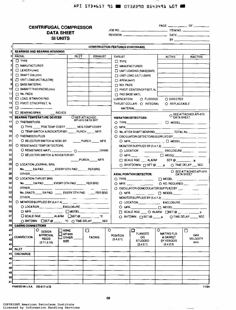
~
A P I STD*b37 95 0732290 0543493 bOT W
THRUST
O TYPE 0 MANUFACTURER
0 UNIT LOADING (MAX)(BAR)
0 UNIT LOAD (ULT.) (BAR)
0 AREA(mm2) 0 NO.PADS
0 PIVOT: CENTEFUOFFSET, %
0 PAD BASE MATL
PAGE OF
JOB NO. ITEM NO.
REVISION DATE
CENTRIFUGAL COMPRESSOR DATA SHEET SI UNITS BY
~ ~~ ~~
ACTIVE INACTIVE
~ ~~
1 CONSTRUCTION FEATURES (CONTINUED)
9 10 11 12 13 14
7 0 SHAFTDIA(mm)
e o UNIT LOAD (ACTIALLOWJ
0 BABBITTTHICKNESS(mm)
0 No.PADS
0 L0AD:B'TWNiONPAD
O PIVOT: CTFUOFFSET, 'Ya - 16 17
0 BASEMATERIAL L
BEARING TEMPERATURE DEVICES
0 THERMISTORS
0 SEE ATTACHED APL670 DATA SHT
U
18 19 20 21 22 23 24 25 26 27 28 29 30 31 32 33 34 35 36
37
151 0 BEARINGSPAN INCHES
0 TYPE -POS TEMP COEFF NEG TEMP COEFF
0 TEMPSWITCH &INDICATORBY:-PURCH- MFR
0 SELECTOR SWITCH B INDIC BY:
0 THERMOCOUPLES
- PURCH __ MFR
0 RESISTANCE TEMP DETECTORS
0 RESISTANCE MAT'L O OHMS 0 SELECTOR SWITCH & INDICATOR BY:
__ PURCH - MFR
0 LOCATION-JOURNAL BRG
No.-EAPAD EVERY OTH PAD - PER BRG
OTHER
O LOCATION-THRUST BRG
No.-EAPAD- EVERY OTH PAD- PER BRG
OTHER
No. (INACT) __ EA PAD __ EVERY OTH PAD __ PER BRG OTHER
0 MONITORSUPPLIED BY (3.4.7.4) 0 LOCATION ENCLOSURE
0 MFR. 0 MODEL
DSCALERGE ALARM O S E T @ "C
SEC 381 0 SHTDWN OSET@ O C 0 TIME DELAY ~ 38
39 40 41 42 43 44
45 46
47 48
49
50
51
39 CASING CONNECTIONS
41 APPROVAL 0 605 42 43
44 INLET
45 DISCHARGE
O o MATING FLG GAS FLANGED
STUDDED BY VENDOR (2.4.2.1) (2.4.2.3)
40 o DESIGN OASME O
OR 8 GASKET VELOCITY POSITION (2.4.2.1)
Wm FACING CONNECTION REQD 0 OTHER
(2.1 1.2.1 O) SIZE
47 48
49
50 I 1 I I 51 I
PRINTED IN USA. DS-617-4 SI 11/94
58
COPYRIGHT American Petroleum InstituteLicensed by Information Handling ServicesCOPYRIGHT American Petroleum InstituteLicensed by Information Handling Services
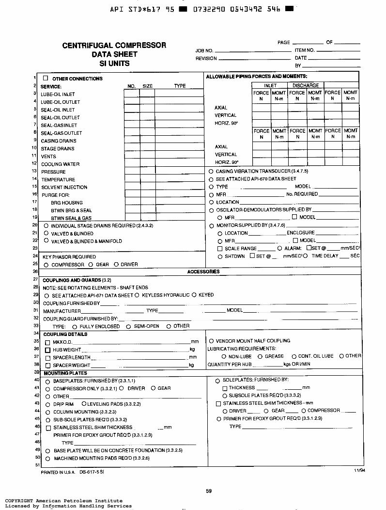
A P I STD*bL7 95 m 0732290 0543492 546 m
25 26 27 28 29 30 31 32
PAGE OF
JOB NO. ITEM NO.
REVISION DATE
CENTRIFUGAL COMPRESSOR DATA SHEET
SI UNITS BY
0 COMPRESSOR 0 GEAR 0 DRIVER ACCESSORIES
COUPLINGS AND GUARDS (3.2) NOTE: SEE ROTATING ELEMENTS - SHAFT ENDS 0 SEE ATTACHED API-671 DATA SHEET 0 KEYLESS HYDRAULIC 0 KEYED
COUPLING FURNISHED BY
MANUFACTURER TYPE MODEL
COUPLING GUARDFURNISHEDBY:
PAGE OF CENTRIFUGAL COMPRESSOR DA
SI UP
33 S4
LUBE-OIL INLET
LUBE-OIL OUTLET
SEAL-OIL INLET
SEAL-OIL OUTLET SEAL-GAS INLET
SEAL-GAS OUTLET
CASING DRAINS
MODEL
No. REQUIRED
BRG HOUSING 0 OSCILATOR-DEMODULATORS SUPPLIED BY
O MFR
0 MONITORSUPPLIED BY (3.4.7.6) ENCLOSURE
0 MODEL
0 SCALERANGE 0 ALARM: OSET @ - mm/SEC
0 SHTDWN 0 SET Q __ mm/SEC20 TIME DELAY - SE(
TYPE: 0 FULLY ENCLOSED 0 SEMI-OPEN 0 OTHER
COUPLING DETAILS I 35 36 S7 38
39 40 41 42 43 44
45 46 47
48 49 50
0 MAX0.D. mm O VENDOR MOUNT HALF COUPLING
HUBWEIGHT kg LUBRICATING REQUIREMENTS:
0 SPACERWEIGHT kg QUANTITY PER HUB kgs OR VMIN
MOUNTINQ PLATES 0 BASEPLATES: FURNISHED BY (3.3.1.1) 0 COMPRESSORONLY (3.3.2.1) 0 DRIVER 0 GEAR 0 THICKNESS mm
O OTHER
0 DRIP RIM
0 SPACERLENGTH mm O NON-LUBE 0 GREASE 0 CONT. OIL LUBE 0 OTHE
0 SOLEPLATES: FURNISHED BY:
0 SUBSOLE PLATES REQ'D (3.3.3.2)
0 LEVELING PADS (3.3.2.2) 0 STAINLESS STEEL SHIM THICKNESS - mm 0 COMPRESSOR - 0 DRIVER- 0 GEAR- 0 COLUMN MOUNTING (3.3.2.3)
0 SUB-SOLE PLATES REQD (3.3.3.2) 0 STAINLESSSTEEL SHIMTHICKNESS mm TYPE
0 PRIMER FOR EPOXY GROUT REQ'D (3.3.1.2.9)
PRIMER FOR EPOXY GROUT REQ'D (3.3.1.2.9) TYPE
0 BASE PLATE WILL BE ON CONCRETE FOUNDATION (3.3.2.5) 0 MACHINED MOUNTING PADS REQ'D (3.3.2.6)
I 11/94 PRINTED IN U.S.A. DS-617-5SI
59
COPYRIGHT American Petroleum InstituteLicensed by Information Handling ServicesCOPYRIGHT American Petroleum InstituteLicensed by Information Handling Services
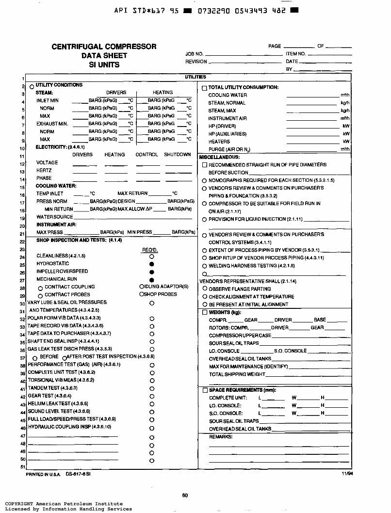
A P I STD*bL7 95 m 0732290 0543493 482 =
2
CENTRIFUGAL COMPRESSOR PAGE OF
JOB NO. ITEM NO. REVISION DATE
DATA SHEET SI UNITS
BY
i ununEs 0 UTILITY CONDITIONS
STEAM: DRIVERS
INLET MIN BARG (kPaG) "C BARG(kPaG) "C NORM
MAX BARG (kPaG) "C
EXHAUSTMIN. BARG (kPaG) "C
BARG(kPaG) OC NORM BARG (kPaG) "C MAX
- -
-- -
3 4
5
6
7
8
9
10
11
12
13
14
15
16
17
18 19
20
HEATING
BARG (kPaG O C
BARG(kPaG "C
- BARG (kPaG -OC
- BARG (kPaG O C
BARG(kPaG "C
BARG (kPaG O C
-
- I
21
22
~
SHOP INSPECTION AND TESTS: (4.1.4)
EI CLEANLINESS(4.2.1.5)
25
27 26
28
29 30 31
32
33 34
35 36
37 38 39 40 41
42
43 44
45
46
REQ'D. O
HYDROSTATIC a
MECHANICALRUN a IMPELLEROVERSPEED O
0 CONTRACT COUPLING OIDLING ADAPTOR(S)
0 CONTRACT PROBES OSHOP PROBES
VARY LUBE 8. SEAL OIL PRESSURES O
POLAR FORMVIB DATA (4.3.4.3.3) O TAPE RECORD VIB DATA (4.3.4.3.6) O TAPE DATATO PURCHASER(4.3.4.3.7) O SHAFT END SEAL INSP (4.3.4.4.1) O GAS LEAK TEST DISCH PRESS (4.3.5.3) O
PERFORMANCE TEST (ûAS) (AIR) (4.3.6.1) O COMPLETE UNIT TEST (4.3.6.2) O TORSIONAL VIB MEAS (4.3.6.2) O TANDEMTEST (4.3.6.3) O GEAR TEST (4.3.6.4) O HELIUM LEAKTEST(4.3.6.5) O SOUND LEVEL TEST(4.3.6.6) O FULL LOAD/SPEED/PRESSTEST(4.3.6.9) O
O
ANDTEMPERATURES(4.3.4.2.5)
0 BEFORE @FTER POST TEST INSPECTION (4.3.6.8)
HYDRAULIC COUPLING INSP (4.3.6.10)
O O O O
47
48 49 50
1 TOTAL UTILITY CONSUMPTION COOLING WATER m3B
STEAM, NORMAL k9ni STEAM, MAX k f l
HP (DRIVER) kw HP (AUXILIARIES) kw HEATERS kw
INSTRUMENT AIR m3h
PURGE (AIR OR N2) m3h ISCELLANEOUS 7 RECOMMENDED STRAIGHT RUN OF PIPE DIAMETERS
BEFORE SUCTION
3 NOMOGRAPHS REQUIRED FOR EACH SECTION (5.3.3.1.5)
3 VENDOR'S REVIEW & COMMENTS ON PURCHASERS
3 COMPRESOR TO BE SUITABLE FOR FIELD RUN IN
PIPING &FOUNDATION (3.5.3.2)
ON AIR (2.1 . î7)
3 PROVISION FOR LIQUID INJECTION (2.1.11)
3 VENDORS REVIEW LCOMMENTSON PURCHASERS
3 EXTENT OF PROCESS PIPING BY VENDOR (3.5.3.1) 3 SHOP FITUP OF VENDOR PROCESS PIPING (4.4.3.11)
3 WELDING HARDNESS TESTING (4.2.1.6)
CONTROL SYSTEMS (3.4.1.1)
3 ENDORS REPRESENTATIVE SHALL (2.1.14)
0 OBSERVE FLANGE PARTING
0 CHECK ALIGNMENT AT TEMPERATURE
0 BE PRESENT AT INITIAL ALIGNMENT
J WEIGHTS (kg): C0MPR.- GEAR- DRIVER BASE
ROTORS: COMPR. DRIVER GEAR COMPRESSOR UPPERCASE
SOUR SEAL OIL TRAPS LO. CONSOLE S.O. CONSOLE
OVERHEADSEALOILTANKS
MAX FOR MAINTENANCE (IDENTIFY)
TOTALSHIPPING WEIGHT
0 SPACE REQUIREMENTS (mm): COMPLETE UNIT L W-H-
LO. CONSOLE: L- W-H- S.O. CONSOLE: L- W-H- SOUR SEAL OIL TRAPS
OVERHEAD SEALOIL TANKS
REMARKS:
COPYRIGHT American Petroleum InstituteLicensed by Information Handling ServicesCOPYRIGHT American Petroleum InstituteLicensed by Information Handling Services
~ ~
A P I STDUb17 75 0732270 0543474 317
APPENDIX B-TYPICAL MATERIAL SPECIFICATIONS FOR MAJOR COMPONENT PARTS
61
COPYRIGHT American Petroleum InstituteLicensed by Information Handling ServicesCOPYRIGHT American Petroleum InstituteLicensed by Information Handling Services
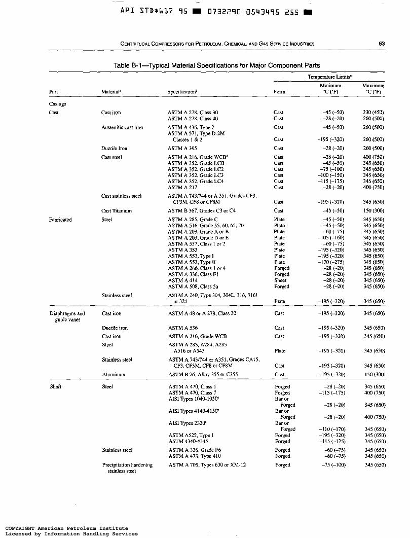
~
A P I S T D * b L ï 95 0732290 0543495 255
CENTRIFUGAL COMPRESSORS FOR PETROLEUM, CHEMICAL, AND GAS SERVICE INDUSTRIES 63
Table B-1 -Typical Material Specifications for Major Component Patts
Part Material"
Temperature Limits' Minimum MtlXimUln
Form 'C ( O F ) 'C ('F)
Cast stainless steel
Cast Titanium Fabricated Steel
~~ ~ ~ ~~ ~~
Casings Cast Cast iron ASTM A 278, Class 30
ASTM A 278, Class 40
ASTM A 436, Type 2 ASTM A 57 1. Type D-2M
Austenitic cast iron
Classes 1 & 2 Ductile Iron ASTM A 395
Cast steel ASTM A 216, Grade WCBd ASTM A 352, Grade LCB ASTM A 352, Grade LC2 ASTM A 352, Grade LC3 ASTM A 352, Grade LC4 ASTM A 217 ASTM A 743/744 or A 351, Grades CF3.
ASTM B 367. Grades C3 or C4
ASTM A 285. Grade C ASTM A 516, Grade 55,60,65,70 ASTM A 203, Grade A or B ASTM A 203, Grade D or E ASTM A 537, Class I or 2 ASTM A 353 ASTM A 553, Type I ASTM A 553, Type II ASTM A 266, Class I or 4 ASTM A 336, Class F1 ASTM A 414 ASTM A 508. Class 5a ASTM A 240, Type 304,304L, 316,3161
CF3M. CF8 or CF8M
Stainless steel or 321
Cast Cast
Cast
Cast Cast Cast Cast Cast Cast Cast Cast
Cast Cast Plate Plate Plate Plate Plate Plate Plate Plate Forged Forged Sheet Forged
Plate
-45 (-50) -28 (-20)
-45 (-50)
-195 (-320)
-28 (-20) -28 (-20) 4 5 (-50)
-75 (-100) -100 (-150) -115 (-175)
-28 (-20)
-1 95 (-320) -45 (-50) 4 5 (-50) -45 (-50) -60 (-75)
-105 (-160) -60 (-75)
-195 (-320) -195 (-320) -170 (-275)
-28 (-20) -28 (-20) -28 (-20) -28 (-20)
-195 (-320)
230 (450) 260 (500) 260 (500)
260 (500) 260 (500) 400 (750) 345 (650) 345 (650) 345 (650) 345 (650) 400 (750)
345 (650)
150 (300) 345 (650) 345 (650) 345 (650) 345 (650) 345 (650) 345 (650) 345 (650) 345 (650) 345 (650) 345 (650) 345 (650) 345 (650)
345 (650)
Diaphragms and Cast iron ASTM A 48 or A 278, Class 30 Cast -195 (-320) 345 (650)
Ductile iron ASTM A 536 Cast -195 (-320) 345 (650) Cast iron ASTM A 216, Grade WCB Cast -195 (-320) 345 (650) Steel
A516 or A543 Plate -195 (-320) 345 (650)
Stainless steel CF3, CF3M, CF8 or CF8M Cast -1 95 (-320) 345 (650)
Aluminum ASTM B 26, Alloy 355 or C355 Cast -195 (-320) 150 (300)
345 (650) Shaít Steel ASTM A 470, Class 1 Forged ASTM A 470, Class 7 Forged -115 (-175) 400 (750) AISI Types 1040-1050' Bar or
Forged -28 (-20) 345 (650) AISI Types 4140-415W Bar or
Forged -28 (-20) 400 (750) AISI Types 2320' Bar or
Forged -110 (-170) 345 (650) ASTM A522, Type 1 Forged -195 (-320) 345 (650) ASTM 4340-4345 Forged -115 (-175) 345 (650)
Stainless steel ASTM A 336, Grade F6 Forged -60 (-75) 345 (650) ASTM A 473, Type 410 Forged -60 (-75) 345 (650)
Precipitation hardening ASTM A 705, Types 630 or XM-12 Forged -75 (-100) 345 (650)
guide vanes
ASTM A 283, A284, A285
ASTM A 743p44 or A351, Grades CA15,
-28 (-20)
stainless steel
COPYRIGHT American Petroleum InstituteLicensed by Information Handling ServicesCOPYRIGHT American Petroleum InstituteLicensed by Information Handling Services
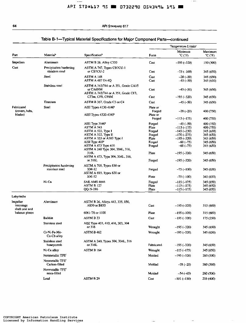
-
A P I STD*bL7 95 m 0732290 0543496 191 m
64 API STANDARD 61 7 ~ ~ ~~
Table 6-1 -Typical Material Specifications for Major Component Parts-continued
Part Material' Specificationb
Temperature Limits'
Minimum Maximum Form "C ("Fì 'C ("Fì
Impellers Aluminum c a s t Precipitation hardening
Steel stainless steel
Stainless steel
Titanium Fabricated Steel
(covers, hubs, blades)
ASTM B 26. Alloy C355
ASTM A 747, Types CB7CU-I or CB7CU-2
ASTM A 148 ASTM A 487 Gs 4 4
ASTM A 7431744 or A 35 i , Grade CAI 5
ASTM A 743I744 or A 35 1, Grade CF3,
ASTM B 367, Grade C3 or C4 AISI Types 4130-414W
AISI Types 4320-4345'
or CA6NM
CF3m. CF8, CFSM
Precipitation hardening stainless steel
Ni-Cu
AISI Type 31W ASTM A 543 ASTM A 522, Type I ASTM A 522, Type II ASTM A 353 or A583 Type I AISI Type 403' ASTM A 473 Type 410 ASTM A 240 Type 304,304L, 316,
ASTM A 473, Type 304,304L, 316,
ASTM A 705, Types 630 or
ASTM A 693, Types 630 or
SAE AMS 4646 ASTM B 127
316L
or 316L
XM-12
XM-12
00-N-286
Cast
Cast cast Cast
Cast
Cast Cast Plate or
Plate or
Forged Plate Forged Forged Plate Forged Forged
Plate
Forged
Forged
Plate
Forged Plate Plate
Forged
Forged
-195 (-320)
-75 (-100)
4 5 (-50) -28 (-20)
4 5 (-50)
-195 (-320)
-45 (-50)
-28 (-20)
-115 (-175)
-45 (-50) -115 (-175) -145 (-230) -170 (-275) -195 (-320)
-60 (-75) -60 (-75)
-195 (-320)
-195 (-320)
-75 (-100)
-75 (-100)
-115 (-175) -115 (-175) -115 (-1751
150 (300)
345 (650) 345 (650) 345 (650)
345 (650)
345 (650) 345 (650)
400 (750)
400 (750) 400 (750) 400 (750) 345 (650) 345 (650) 345 (650) 345 (650) 345 (650)
345 (650)
345 (650)
345 (650)
345 (650) 345 (650) 345 (650) 345 (650) _ - . , ~,
Labyrinths
Impeller Aluminum interstage shaft seal and balance piston
ASTM B 26, Alloys 443,335,850, A850 or B850 Cast -195 (-320) 315 (600)
6061-T6or 1100 Plate -195 (-320) 315 (600) Babbitt ASTM B 23 Cast -195 (-320) 175 (350) Stainless steel AISI Type 403,410,416,303,304
or 316 Wrought -195 (-320) 345 (650) Cr-Ni-Fe-Mo- ASTM B 462
Cu-Cb alloy Wrought -195 (-320) 345 (650)
Stainless steel honeycomb or 3i6L Fabricated -195 (-320) 345 (650)
Ni-Cu alloy ASTM B 164 Wrought -1 15 (-175) 345 (650) Nonmetallic TFE' Molded -195 (-320) 260 (500)
ASTM A 240, Types 304,304L, 316
Nonmetallic TFE' Carbon-filled
Nonmetallic TFE' mica-filled
Lead
Molded -28 (-20) 260 (500)
ASTM B 29 Molded -54 (-65) 260 (500) Cast -101 (-150) 205 (400)
COPYRIGHT American Petroleum InstituteLicensed by Information Handling ServicesCOPYRIGHT American Petroleum InstituteLicensed by Information Handling Services
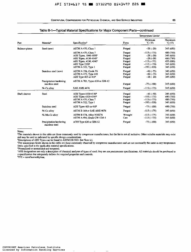
A P I STDUbL7 95 W 0732290 0543497 028 W
CENTRIFUGAL COMPRESSORS FOR PETROLEUM, CHEMICAL, AND GAS SERVICE INDUSTRIES 65
Table B-1 -Typical Material Specifications for Major Component Parts-continued
Part Material' Specificationb
Temperature Limits'
Minimum Maximum Form 'C ('F) 'C ('F)
Balance piston Steel (new) ASTM A 470, Class 1
ASTM A 470, Class 7 AISI Types, 1040-105V AISI TYPS, 4130-4145' AISI Types, 4330,4345' AISI Type 232F ASTM A 522, Type 1
ASTM A 336, Grade F6 ASTM A 473, Type 410 AISI Type 403 or 41F ASTM A 705, Types 630 or XM-12
Stainless steel (new)
Precipitation hardening
Ni-Cu alloy SAE AMS 4676 stainless steel
Forged Forged Forged Forged Forged Forged Forged Forged Forged Forged
Forged Forged
-28 (-20) -115 (-175)
-28 (-20) -28 (-20)
-115 (-175) -112 (-170) -1 95 (-320)
-60 (-75) -60 (-75) -28 (-20)
-75 (-100) -115 (-175)
345 (650) 400 (750) 345 (650) 400 (750) 455 (850) 345 (650) 345 (650) 345 (650) 345 (650) 345 (650)
345 (650) 345 (650)
Shaft sleeves Steel AISI Types 4130-415P
ASTM A 470, Class 7 ASTM A 522, Type I
AISI Types 4320-4345'
Stainless steel Ni-Cu alloy Ni-Mo-Cr alloy
Precipitation hardening
AISI Types 403 or 41V ASTM B 164 or SAE AMS 4676 ASTM B 574, Alloy N10276 ASTM A 494, Grade CW-12M-I
A705 Type 630 or XM-12 stainless steel
Forged Forged Forged Forged
Forged
Forged Wrought Cast Forged
-45 (-50) - I I5 (-175) -115 (-175) -195 (-320)
-75 (-100) -115 (-175) -115 (-175) -115 (-175) -75 (-100)
345 (650) 400 (750) 400 (750) 345 (650)
400 (750) 345 (650) 345 (650) 345 (650) 345 (650)
Notes: T h e materials shown in this table are those commonly used by compressor manufacturers, but the list is not all inclusive. Other suitable materials may exist and may be used as indicated by specific design considerations. bDescriptions of AISI Types can be found in ASTM DS 56D. See Note (e). The temperature limits shown in this table are those commonly observed by compressor manufacturers and are not necessarily the same as any temperature limits specified in the applicable material specifications. dNormalized or normalized and tempered. 'AISI designations are only a description of chemical analyses of types of steel; they are not procurement specifications. All materials should be purchased to a specification that adequately defines the required properties and controls. 'TFE = tetrafluoroethylene.
COPYRIGHT American Petroleum InstituteLicensed by Information Handling ServicesCOPYRIGHT American Petroleum InstituteLicensed by Information Handling Services
A P I STD*6L7 95 O732290 0543498 T64
APPENDIX C-CENTRIFUGAL COMPRESSOR VENDOR DRAWING AND DATA REQUIREMENTS
67
COPYRIGHT American Petroleum InstituteLicensed by Information Handling ServicesCOPYRIGHT American Petroleum InstituteLicensed by Information Handling Services
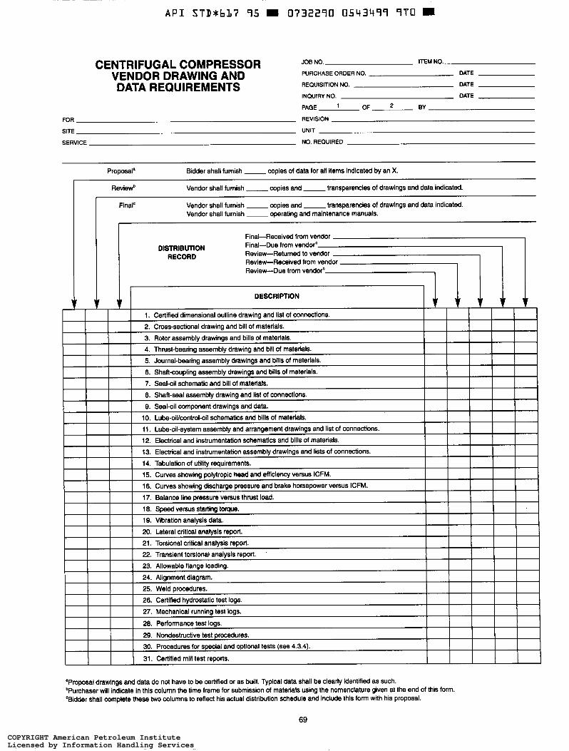
A P I STD*bL7 95 0732290 0543499 9 T O
CENTRIFUGAL COMPRESSOR VENDOR DRAWING AND DATA REQUIREMENTS
JOB NO. ITEM NO.
PURCHASE ORDER NO. DATE
REQUISITION NO. DATE
INQUIRY NO. DATE
PAGE ' OF * BY
REVISION FOR
SITE UNIT
SERVICE NO. REQUIRED
Proposal'
Revied
Finalc
Bidder shall furnish - copies of data for all items indicated by an X.
Vendor shall furnish __ copies and -transparencies of drawings and data indicated.
Vendor shall furnish - copies and - transparencies of drawings and data indicated. Vendor shall furnish ~ operating and maintenance manuals.
Final-Received from vendor Final-Due from vendor Review-Returned to ve Review-Received from Review-Due from vend
DISTRIBUTION RECORD
"Proposal drawings and data do not have to be certified or as built. Typical data shall be clearly identified as such. bPurchaser will indicate in this column the time frame for submission of materials using the nomenclature given at the end of this form. 'Bidder shall complete these two columns to reflect his actual distribution schedule and include this form with his proposal.
69
COPYRIGHT American Petroleum InstituteLicensed by Information Handling ServicesCOPYRIGHT American Petroleum InstituteLicensed by Information Handling Services
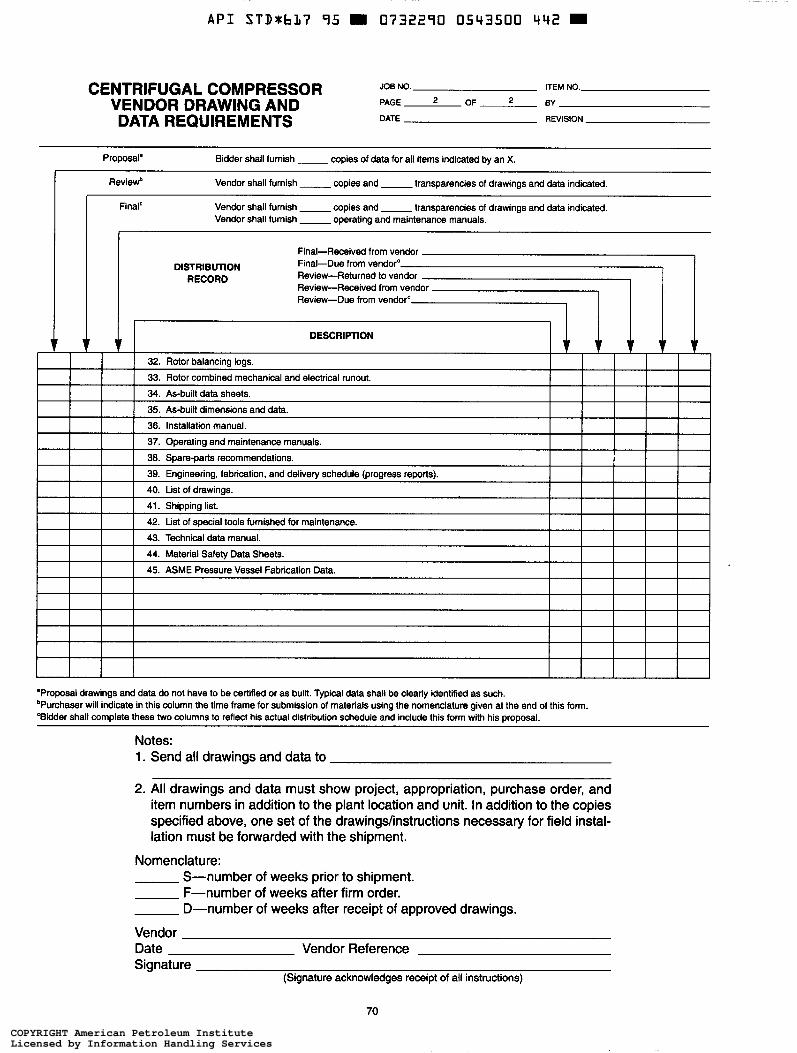
A P I STDabL7 95 H 0732290 0543500 442 H
CENTRIFUGAL COMPRESSOR VENDOR DRAWING AND DATA REQUIREMENTS
JOE NO. ITEM NO.
PAGE OF 2 BY
DATE REVISION
Proposal' Bidder shall furnish - copies of data for all items indicated by an X.
Revied
Final'
I
Vendor shall furnish __ copies and -transparencies of drawings and data indicated.
Vendor shall furnish -copies and -transparencies of drawings and data indicated. Vendor shall furnish - operating and maintenance manuals.
Final-Received from vendor Final-Due from vendor'
Review-Received from vendor Review-Returned to vendor
Review-Due from vendorc
DISTRIBUTION RECORD
I I I I I l I I I I t t t t t DESCRIPTION
32. Rotor balancing logs.
33. Rotor combined mechanical and electrical runout.
34. As-built data sheets.
t t C
35. As-built dimensions and data.
36. Installation manual.
37. Operating and maintenance manuals.
38. %are-Darts recommendations. ~ ~
39. Engineering, fabrication, and delNety schedule (progress reports).
40. List of drawings.
41. Shippina list.
42. List of special tools furnished for maintenance.
43. Technical data manual.
44. Material Safety Data Sheets.
45. ASME Pressure Vessel Fabrication Data.
'Proposai drawings and data do not have to be certified or as built. Typical data shall be clearly identified as such. bPurchaser will indicate in this column the time frame for submission of materials using the nomenclature given at the end of this form. 'Bidder shall complete these two columns to reflect his actual distribution schedule and include this form with his proposal.
Notes: 1. Send all drawings and data to
2. All drawings and data must show project, appropriation, purchase order, and item numbers in addition to the plant location and unit. In addition to the copies specified above, one set of the drawingdinstructions necessary for field instal- lation must be forwarded with the shipment.
Nomenclature: S-number of weeks prior to shipment. F-number of weeks after firm order. D-number of weeks after receipt of approved drawings.
Vendor Date Vendor Reference Signature
(Signature acknowledges receipt of all instructions)
70
COPYRIGHT American Petroleum InstituteLicensed by Information Handling ServicesCOPYRIGHT American Petroleum InstituteLicensed by Information Handling Services
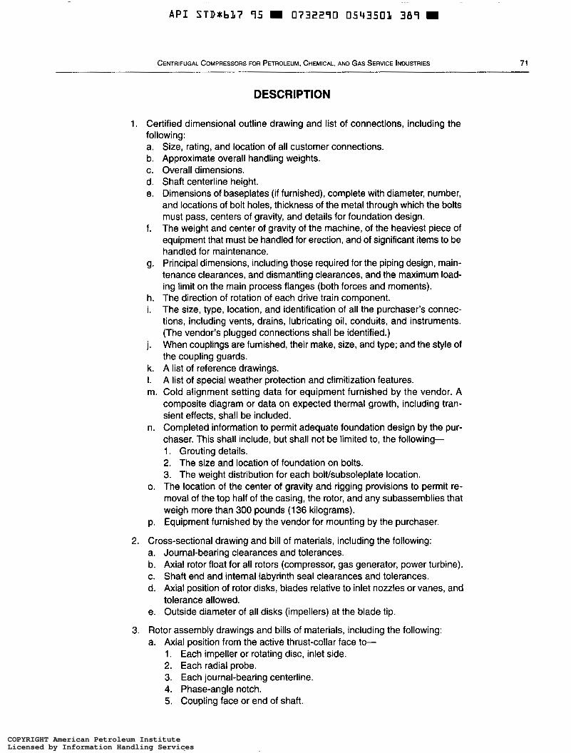
A P I S T D * h L ï 95 m 0732290 0543503 389 m
CENTRIFUGAL COMPRESSORS FOR PETROLEUM, CHEMICAL, AND GAS SERVICE INDUSTRIES 71
DESCRIPTION
1. Certified dimensional outline drawing and list of connections, including the following: a. b.
d. e.
C.
f.
g.
h. i.
i.
k. I. m.
n.
O.
P.
Size, rating, and location of all customer connections. Approximate overall handling weights. Overall dimensions. Shaít centerline height. Dimensions of baseplates (if furnished), complete with diameter, number, and locations of bolt holes, thickness of the metal through which the bolts must pass, centers of gravity, and details for foundation design. The weight and center of gravity of the machine, of the heaviest piece of equipment that must be handled for erection, and of significant items to be handled for maintenance. Principal dimensions, including those required for the piping design, main- tenance clearances, and dismantling clearances, and the maximum load- ing limit on the main process flanges (both forces and moments). The direction of rotation of each drive train component. The size, type, location, and identification of all the purchaser’s connec- tions, including vents, drains, lubricating oil, conduits, and instruments. (The vendor’s plugged connections shall be identified.) When couplings are furnished, their make, size, and type; and the style of the coupling guards. A list of reference drawings. A list of special weather protection and climitization features. Cold alignment setting data for equipment furnished by the vendor. A composite diagram or data on expected thermal growth, including tran- sient effects, shall be included. Completed information to permit adequate foundation design by the pur- chaser. This shall include, but shall not be limited to, the following- 1. Grouting details. 2. The size and location of foundation on bolts. 3. The weight distribution for each bolt/subsoleplate location. The location of the center of gravity and rigging provisions to permit re- moval of the top half of the casing, the rotor, and any subassemblies that weigh more than 300 pounds (1 36 kilograms). Equipment furnished by the vendor for mounting by the purchaser.
2. Cross-sectional drawing and bill of materials, including the following: a. Journal-bearing clearances and tolerances. b. Axial rotor float for all rotors (compressor, gas generator, power turbine). c. Shaft end and internal labyrinth seal clearances and tolerances. d. Axial position of rotor disks, blades relative to inlet nozzles or vanes, and
tolerance allowed. e. Outside diameter of all disks (impellers) at the blade tip.
3. Rotor assembly drawings and bills of materials, including the following: a. Axial position from the active thrust-collar face to-
1. Each impeller or rotating disc, inlet side. 2. Each radial probe. 3. Each journal-bearing centerline. 4. Phase-angle notch. 5. Coupling face or end of shaft.
COPYRIGHT American Petroleum InstituteLicensed by Information Handling ServicesCOPYRIGHT American Petroleum InstituteLicensed by Information Handling Services
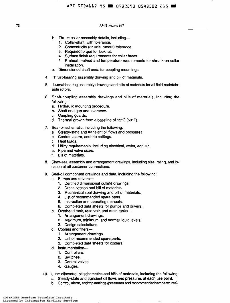
A P I STDrbL7 95 0732290 0543502 215 W
72 API STANDARD 617
b. Thrust-collar assembly details, including- 1. Collar-shaft, with tolerance. 2. Concentricity (or axial runout) tolerance. 3. Required torque for locknut. 4. Surface finish requirements for collar faces. 5. Preheat method and temperature requirements for shrunk-on collar
installation. c. Dimensioned shaft ends for coupling mountings.
4. Thrust-bearing assembly drawing and bill of materials.
5. Journal-bearing assembly drawings and bills of materials for all field-maintain- able rotors.
6. Shaft-coupling assembly drawings and bills of materials, including the following: a. Hydraulic mounting procedure. b. Shaft end gap and tolerance. c. Coupling guards. d. Thermal growth from a baseline of 15°C (59°F).
7. Seal-oil schematic, including the following: a. Steady-state and transient oil flows and pressures. b. Control, alarm, and trip settings. c. Heat loads. d. Utility requirements, including electrical, water, and air. e. Pipe and valve sizes. f. Bill of materials.
8. Shaft-seal assembly and arrangement drawings, including size, rating, and lo- cation of all customer connections.
9. Seal-oil component drawings and data, including the following: a. Pumps and drivers-
1. Certified dimensional outline drawings. 2. Cross-section and bill of materials. 3. Mechanical seal drawing and bill of materials. 4. List of recommended spare parts. 5. Instruction and operating manuals. 6. Completed data sheets for pumps and drivers.
b. Overhead tank, reservoir, and drain tanks- 1. Arrangement drawings. 2. Maximum, minimum, and normal liquid levels. 3. Design calculations.
1. Arrangement drawings. 2. List of recommended spare parts. 3. Completed data sheets for coolers.
d. Instrumentation- 1. Controllers. 2. Switches. 3. Control valves. 4. Gauges.
1 O. Lube-oil/control-oil schematics and bills of materials, including the following: a. Steady-state and transient oil flows and pressures at each use point. b. Control, alarm, and trip settings (pressures and recommended temperatures).
c. Coolers and filters-
COPYRIGHT American Petroleum InstituteLicensed by Information Handling ServicesCOPYRIGHT American Petroleum InstituteLicensed by Information Handling Services
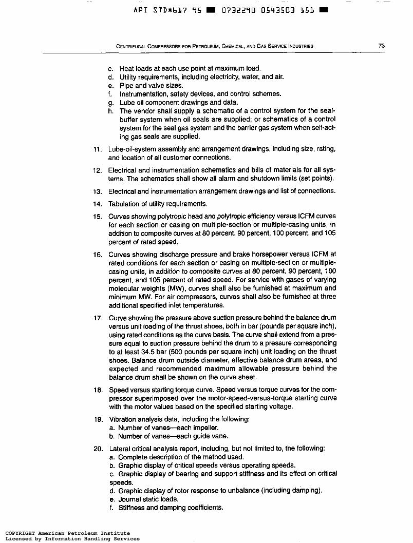
A P I STD*b17 95 m O732290 0543503 '151 m
CENTRIFUGAL COMPRESSORS FOR PETROLEUM, CHEMICAL, AND GAS SERVICE INDUSTRIES 73
11.
12.
13.
14.
15.
16.
17.
18.
19.
20.
c. Heat loads at each use point at maximum load. d. Utility requirements, including electricity, water, and air. e. Pipe and valve sizes. f. Instrumentation, safety devices, and control schemes. g. Lube oil component drawings and data. h. The vendor shall supply a schematic of a control system for the seal-
buffer system when oil seals are supplied; or schematics of a control system for the seal gas system and the barrier gas system when self-act- ing gas seals are supplied.
Lube-oil-system assembly and arrangement drawings, including size, rating, and location of all customer connections.
Electrical and instrumentation schematics and bills of materials for all sys- tems. The schematics shall show all alarm and shutdown limits (set points).
Electrical and instrumentation arrangement drawings and list of connections.
Tabulation of utility requirements.
Curves showing polytropic head and polytropic efficiency versus ICFM curves for each section or casing on multiple-section or multiple-casing units, in addition to composite curves at 80 percent, 90 percent, 1 O0 percent, and 105 percent of rated speed.
Curves showing discharge pressure and brake horsepower versus ICFM at rated conditions for each section or casing on multiple-section or multiple- casing units, in addition to composite curves at 80 percent, 90 percent, 1 O0 percent, and 105 percent of rated speed. For service with gases of varying molecular weights (MW), curves shall also be furnished at maximum and minimum MW. For air compressors, curves shall also be furnished at three additional specified inlet temperatures.
Curve showing the pressure above suction pressure behind the balance drum versus unit loading of the thrust shoes, both in bar (pounds per square inch), using rated conditions as the curve basis. The curve shall extend from a pres- sure equal to suction pressure behind the drum to a pressure corresponding to at least 34.5 bar (500 pounds per square inch) unit loading on the thrust shoes. Balance drum outside diameter, effective balance drum areas, and expected and recommended maximum allowable pressure behind the balance drum shall be shown on the curve sheet.
Speed versus starting torque curve. Speed versus torque curves for the com- pressor superimposed over the motor-speed-versus-torque starting curve with the motor values based on the specified starting voltage.
Vibration analysis data, including the following: a. Number of vanes-each impeller. b. Number of vanes-each guide vane.
Lateral critical analysis report, including, but not limited to, the following: a. Complete description of the method used. b. Graphic display of critical speeds versus operating speeds. c. Graphic display of bearing and support stiffness and its effect on critical speeds. d. Graphic display of rotor response to unbalance (including damping). e. Journal static loads. f. Stiffness and damping coefficients.
COPYRIGHT American Petroleum InstituteLicensed by Information Handling ServicesCOPYRIGHT American Petroleum InstituteLicensed by Information Handling Services
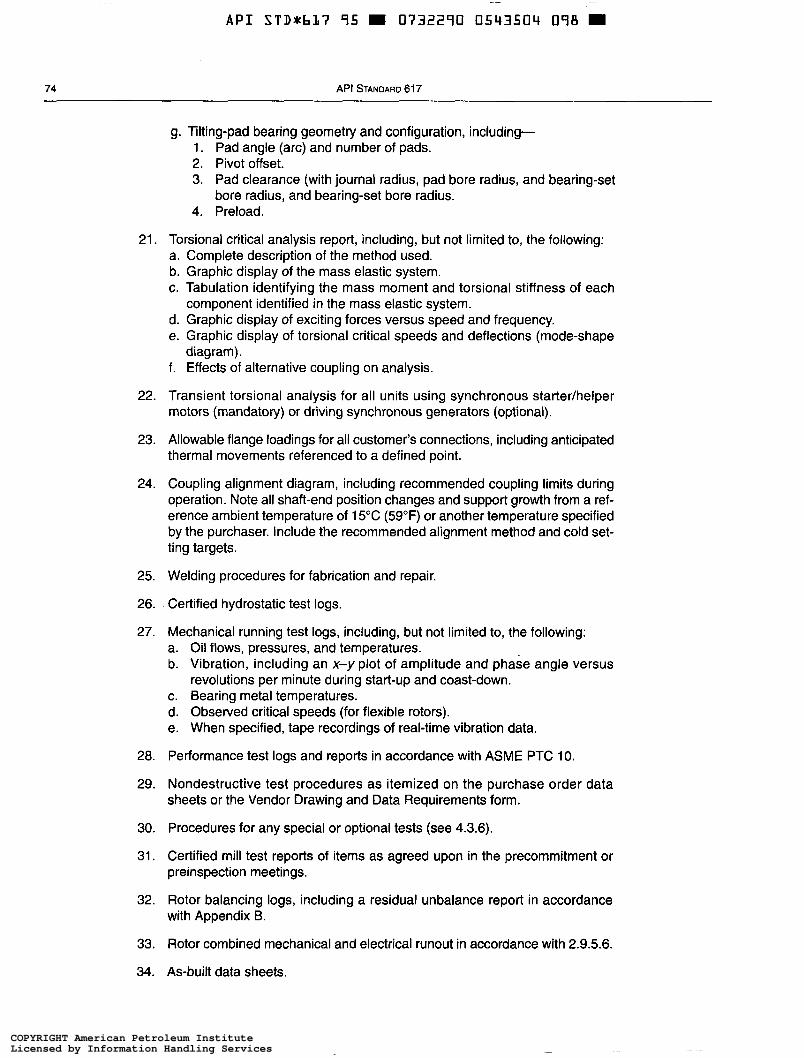
~
A P I STD*bL7 95 0732290 0543504 098
74 API STANDARD 61 7
g. Tilting-pad bearing geometry and configuration, including- 1. Pad angle (arc) and number of pads. 2. Pivot offset. 3. Pad clearance (with journal radius, pad bore radius, and bearing-set
bore radius, and bearing-set bore radius. 4. Preload.
21.
22.
23.
24.
25.
26.
27.
28.
29.
30.
31.
32.
33.
34.
Torsional critical analysis report, including, but not limited to, the following: a. Complete description of the method used. b. Graphic display of the mass elastic system. c. Tabulation identifying the mass moment and torsional stiffness of each
d. Graphic display of exciting forces versus speed and frequency. e. Graphic display of torsional critical speeds and deflections (mode-shape
diagram). f. Effects of alternative coupling on analysis.
Transient torsional analysis for all units using synchronous startedhelper motors (mandatory) or driving synchronous generators (optional).
Allowable flange loadings for all customer’s connections, including anticipated thermal movements referenced to a defined point.
Coupling alignment diagram, including recommended coupling limits during operation. Note all shaft-end position changes and support growth from a ref- erence ambient temperature of 15°C (59°F) or another temperature specified by the purchaser. Include the recommended alignment method and cold set- ting targets.
Welding procedures for fabrication and repair.
Certified hydrostatic test logs.
Mechanical running test logs, including, but not limited to, the following: a. Oil flows, pressures, and temperatures. b. Vibration, including an x-y plot of amplitude and phase angle versus
revolutions per minute during start-up and coast-down. c. Bearing metal temperatures. d. Observed critical speeds (for flexible rotors). e. When specified, tape recordings of real-time vibration data.
Performance test logs and reports in accordance with ASME PTC 1 O.
Nondestructive test procedures as itemized on the purchase order data sheets or the Vendor Drawing and Data Requirements form.
Procedures for any special or optional tests (see 4.3.6).
Certified mill test reports of items as agreed upon in the precommitment or preinspection meetings.
Rotor balancing logs, including a residual unbalance report in accordance with Appendix B.
Rotor combined mechanical and electrical runout in accordance with 2.9.5.6.
component identified in the mass elastic system.
As-built data sheets.
COPYRIGHT American Petroleum InstituteLicensed by Information Handling ServicesCOPYRIGHT American Petroleum InstituteLicensed by Information Handling Services
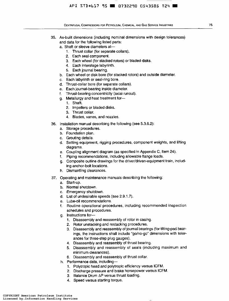
~~ -
A P I STDxbL7 95 = 0732290 0543505 T 2 4
CENTRIFUGAL COMPRESSORS FOR PETROLEUM, CHEMICAL, AND GAS SERVICE INDUSTRIES 75
35. As-built dimensions (including nominal dimensions with design tolerances) and data for the following listed parts: a. Shaft or sleeve diameters at-
b.
d. e. f. 9.
C.
1. Thrust collar (for separate collars). 2. Each seal component. 3. Each wheel (for stacked rotors) or bladed disks. 4. Each interstage labyrinth. 5. Each journal bearing. Each wheel or disk bore (for stacked rotors) and outside diameter. Each labyrinth or seal-ring bore. Thrust-collar bore (for separate collars). Each journal-bearing inside diameter. Thrust-bearing concentricity (axial runout). Metallurgy and heat treatment for- 1. Shaft. 2. Impellers or bladed disks. 3. Thrust collar. 4. Blades, vanes, and nozzles.
36. Installation manual describing the following (see 5.3.6.2): a. b. C. d.
e. f. g.
h.
Storage procedures. Foundation plan. Grouting details. Setting equipment, rigging procedures, component weights, and lifting diagrams. Coupling alignment diagram (as specified in Appendix C, Item 24). Piping recommendations, including allowable flange loads. Composite outline drawings for the driveddriven-equipment train, includ- ing anchor-bolt locations. Dismantling clearances.
37. Operating and maintenance manuals describing the following: a. b.
d. e. f.
9.
C.
h.
Start-up. Normal shutdown. Emergency shutdown. List of undesirable speeds (see 2.9.1.7). Lube-oil recommendations. Routine operational procedures, including recommended inspection schedules and procedures. Instructions for- 1. Disassembly and reassembly of rotor in casing. 2. Rotor unstacking and restacking procedures. 3. Disassembly and reassembly of journal bearings (for tilting-pad bear-
ings, the instructions shall include “go/no-go” dimensions with toler- ances for three-step plug gauges).
4. Disassembly and reassembly of thrust bearing. 5. Disassembly and reassembly of seals (including maximum and
minimum clearances). 6. Disassembly and reassembly of thrust collar. Performance data, including- 1. Polytropic head and polytropic efficiency versus ICFM. 2. Discharge pressure and brake horsepower versus ICFM. 3. Balance Drum AP versus thrust loading. 4. Speed versus starting torque.
COPYRIGHT American Petroleum InstituteLicensed by Information Handling ServicesCOPYRIGHT American Petroleum InstituteLicensed by Information Handling Services
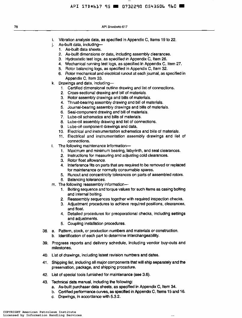
~
A P I STDxbl17 95 0732290 054350b 9b0 =
76 API STANDARD 61 7
38.
39.
40.
41.
42.
43.
i. Vibration analysis data, as specified in Appendix C, Items 19 to 22. j. As-built data, including-
1. As-built data sheets. 2. As-built dimensions or data, including assembly clearances. 3. Hydrostatic test logs, as specified in Appendix C, Item 26. 4. Mechanical running test logs, as specified in Appendix C, Item 27. 5. Rotor balancing logs, as specified in Appendix C, Item 32. 6. Rotor mechanical and electrical runout at each journal, as specified in
Appendix C, Item 33. k. Drawings and data, including-
1. 2. 3. 4. 5. 6. 7.
9. 1 o. 11.
a.
Certified dimensional outline drawing and list of connections. Cross-sectional drawing and bill of materials. Rotor assembly drawings and bills of materials. Thrust-bearing assembly drawing and bill of materials. Journal-bearing assembly drawings and bills of materials. Seal-component drawing and bill of materials. Lube-oil schematics and bills of materials. Lube-oil assembly drawing and list of connections. Lube-oil component drawings and data. Electrical and instrumentation schematics and bills of materials. Electrical and instrumentation assembly drawings and list of connections.
I. The following maintenance information- 1. Maximum and minimum bearing, labyrinth, and seal clearances. 2. Instructions for measuring and adjusting cold clearances. 3. Rotor float allowance. 4. Interference fits on parts that are required to be removed or replaced
for maintenance or normally consumable spares. 5. Runout and concentricity tolerances on parts of assembled rotors. 6. Balancing tolerances.
1. Bolting sequence and torque values for such items as casing bolting and internal bolting.
2. Reassembly sequences together with required inspection checks. 3. Adjustment procedures to achieve required positions, clearances,
and float. 4. Detailed procedures for preoperational checks, including settings
and adjustments. 5. Coupling installation procedures.
m. The following reassembly information-
a. Pattern, stock, or production numbers and materials or construction. b. Identification of each part to determine interchangeability.
Progress reports and delivery schedule, including vendor buy-outs and milestones.
List of drawings, including latest revision numbers and dates.
Shipping list, including all major components that will ship separately and the preservation, package, and shipping procedure.
List of special tools furnished for maintenance (see 3.6). Technical data manual, including the following: a. As-built purchaser data sheets, as specified in Appendix C, Item 34. b. Certified performance curves, as specified in Appendix C, Items 15 and 16. c. Drawings, in accordance with 5.3.2.
COPYRIGHT American Petroleum InstituteLicensed by Information Handling ServicesCOPYRIGHT American Petroleum InstituteLicensed by Information Handling Services
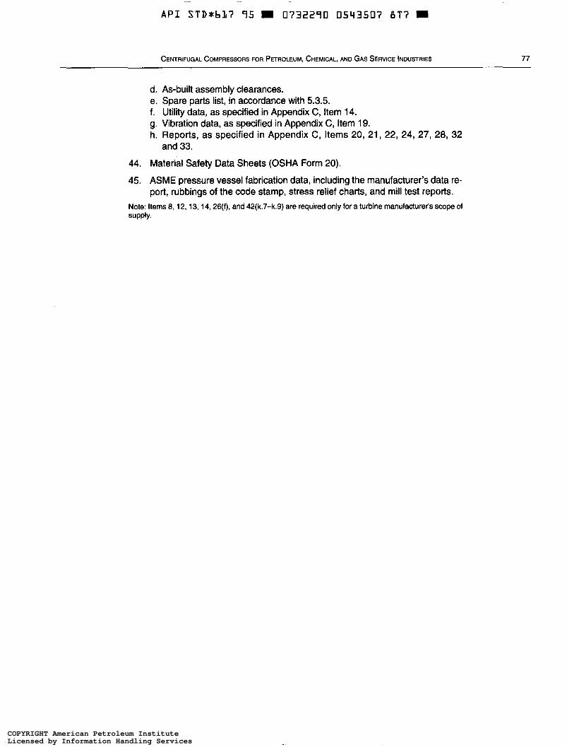
~
A P I STD*b17 95 m 0732290 0543507 8 T ï m
CENTRIFUGAL COMPRESSORS FOR PETROLEUM, CHEMICAL, AND GAS SERVICE INDUSTRIES 77
d. e. f. 9. h.
As-built assembly clearances. Spare parts list, in accordance with 5.3.5. Utility data, as specified in Appendix C, Item 14. Vibration data, as specified in Appendix C, Item 19. Reports, as specified in Appendix C, Items 20, 21, 22, 24, 27, 28, 32 and 33.
44. Material Safety Data Sheets (OSHA Form 20).
45. ASME pressure vessel fabrication data, including the manufacturer's data re- port, rubbings of the code stamp, stress relief charts, and mill test reports.
Note: Items 8.12, 13, 14, 26(f), and 42(k.7-k.9) are required only for a turbine manufacturer's scope of supply.
COPYRIGHT American Petroleum InstituteLicensed by Information Handling ServicesCOPYRIGHT American Petroleum InstituteLicensed by Information Handling Services
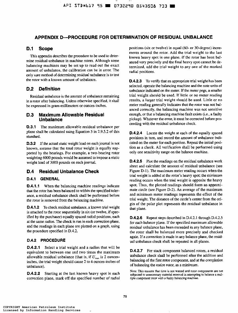
~
A P I S T D t b L 7 95 = 0732290 0543508 733
APPENDIX D-PROCEDURE FOR DETERMINATION OF RESIDUAL UNBALANCE
D.1 Scope This appendix describes the procedure to be used to deter-
mine residual unbalance in machine rotors. Although some balancing machines may be set up to read out the exact amount of unbalance, the calibration can be in error. The only sure method of determining residual unbalance is to test the rotor with a known amount of unbalance.
0.2 Definition Residual unbalance is the amount of unbalance remaining
in a rotor after balancing. Unless otherwise specified, it shall be expressed in gram-millimeters or ounces-inches.
D.3 Maximum Allowable Residual Unbalance
D.3.1 The maximum allowable residual unbalance per plane shall be calculated using Equation 5 in 2.9.5.2 of this standard.
D.3.2 If the actual static weight load on each journal is not known, assume that the total rotor weight is equally sup- ported by the bearings. For example, a two-bearing rotor weighting 6000 pounds would be assumed to impose a static weight load of 3000 pounds on each journal.
D.4 Residual Unbalance Check D.4.1 GENERAL
0.4.1.1 When the balancing machine readings indicate that the rotor has been balanced to within the specified toler- ance, a residual unbalance check shall be performed before the rotor is removed from the balancing machine.
D.4.1.2 To check residual unbalance, a known trial weight is attached to the rotor sequentially in six (or twelve, if spec- ified by the purchaser) equally spaced radial positions, each at the same radius. The check is run in each correction plane, and the readings in each plane are plotted on a graph, using the procedure specified in D.4.2.
D.4.2 PROCEDURE
D.4.2.1 Select a trial weight and a radius that will be equivalent to between one and two times the maximum allowable residual unbalance (that is, if U,, is 2 ounces- inches, the trial weight should cause 2 to 4 ounces-inches of unbalance).
D.4.2.2 Starting at the last known heavy spot in each correction plane, mark off the specified number of radial
positions (six or twelve) in equal (60- or 30-degree) incre- ments around the rotor. Add the trial weight to the last known heavy spot in one plane. If the rotor has been bal- anced very precisely and the final heavy spot cannot be de- termined, add the trial weight to any one of the marked radial positions.
D.4.2.3 To verify that an appropriate trial weight has been selected, operate the balancing machine and the note units of unbalance indicated on the meter. If the meter pegs, a smaller trial weight should be used. If little or no meter reading results, a larger trial weight should be used. Little or no meter reading generally indicates that the rotor was not bal- anced correctly, the balancing machine was not sensitive enough, or that a balancing machine fault exists (i.e., a faulty pickup). Whatever the error, it must be corrected before pro- ceeding with the residual unbalance check.
D.4.2.4 Locate the weight at each of the equally spaced positions in turn, and record the amount of unbalance indi- cated on the meter for each position. Repeat the initial posi- tion as a check. All verification shall be performed using only one sensitivity range on the balance machine.
D.4.2.5 Plot the readings on the residual unbalance work sheet and calculate the amount of residual unbalance (see Figure D-i). The maximum meter reading occurs when the trial weight is added at the rotor’s heavy spot; the minimum reading occurs when the trial weight is opposite the heavy spot. Thus, the plotted readings should form an approxi- mate circle (see Figure D-2). An average of the maximum and minimum meter readings represents the effect of the trial weight. The distance of the circle’s center from the ori- gin of the polar plot represents the residual unbalance in that plane.
D.4.2.6 Repeat steps described in D.4.2.1 through D.4.2.5 for each balance plane. If the specified maximum allowable residual unbalance has been exceeded in any balance plane, the rotor shall be balanced more precisely and checked again. If a correction is made in any balance plane, the resid- ual unbalance check shall be repeated in all planes.
D.4.2.7 For stack component balanced rotors, a residual unbalance check shall be performed after the addition and balancing of the first rotor component, and at the completion of balancing the entire rotor, as a minimum. Note: This ensures that time is not wasted and rotor components are not subjected to unnecessary material removal in attempting to balance a mul- tiple component rotor with a faulty balancing machine.
79
COPYRIGHT American Petroleum InstituteLicensed by Information Handling ServicesCOPYRIGHT American Petroleum InstituteLicensed by Information Handling Services
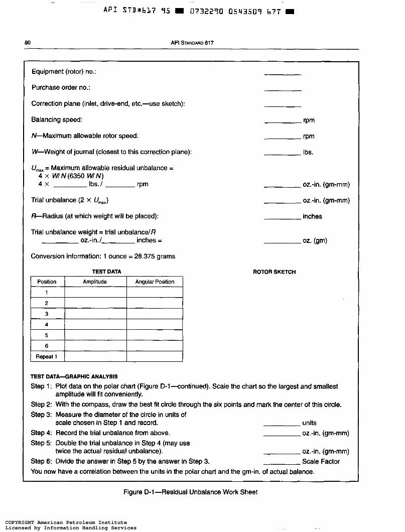
API STD*bL7 95 9 0732290 0543509 b ï T 9
Position
1
80 API STANDARD 61 7
Amplitude Angular Position
Equipment (rotor) no.:
Purchase order no.:
Correction plane (inlet, drive-end, etc.-use sketch):
Balancing speed:
&Maximum allowable rotor speed:
W-Weight of journal (closest to this correction plane):
U,, = Maximum allowable residual unbalance = 4 X WlN(6350 W I N ) 4 x Ibs. I rPm
Trial unbalance (2 x U,,,=)
%Radius (at which weight will be placed):
Trial unbalance weight = trial unbalancelß oz.4n.l inches =
Conversion information: 1 ounce = 28.375 grams
TEST DATA
2
3
1 4 1
I Repeat1 1 l I
rPm
Ibs.
oz.-in. (gm-mm)
oz.-in. (gm-mm)
inches
ROTOR SKETCH
TEST DATA4RAPHIC ANALYSIS
Step 1: Plot data on the polar chart (Figure D-l-continued). Scale the chart so the largest and smallest
Step 2: With the compass, draw the best fit circle through the six points and mark the center of this circle. Step 3: Measure the diameter of the circle in units of
scale chosen in Step 1 and record. Step 4: Record the trial unbalance from above. Step 5: Double the trial unbalance in Step 4 (may use
twice the actual residual unbalance). Step 6: Divide the answer in Step 5 by the answer in Step 3. You now have a correlation between the units in the polar chart and the gm-in. of actual balance.
amplitude will fit conveniently.
units oz.-in. (gm-mm)
oz.-in. (gm-mm) Scale Factor
Figure D-1-Residual Unbalance Work Sheet
COPYRIGHT American Petroleum InstituteLicensed by Information Handling ServicesCOPYRIGHT American Petroleum InstituteLicensed by Information Handling Services
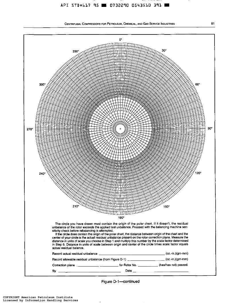
~
A P I S T D M b 3 7 95 = O732290 0543530 391
CENTRIFUGAL COMPRESSORS FOR PETROLEUM, CHEMICAL, ANO GAS SERVICE INDUSTRIES a i
270" 90"
i aoo The circle you have drawn must contain the origin of the polar chart. If it doesn't, the residual
unbalance of the rotor exceeds the applied test unbalance. Proceed with the balancing machine sen- sitivity check before rebalancing is attempted.
If the circle does contain the origin of the polar chart, the distance between origin of the chart and the center of your circle is the actual residual unbalance present on the rotor correction plane. Measure the distance in units of scale you choose in Step 1 and multiply this number by the scale factor determined in Step 6. Distance in units of scale between origin and center of the circle times scale factor equals actual residual balance.
Record actual residual unbalance (oz.-in.)(gm-mm)
Record allowable residual unbalance (from Figure D-1) (oz.-in.)(gm-mm)
Correction plane for Rotor No. (hadhas not) passed.
BY Date
Figure D-1 4ontinued
COPYRIGHT American Petroleum InstituteLicensed by Information Handling ServicesCOPYRIGHT American Petroleum InstituteLicensed by Information Handling Services
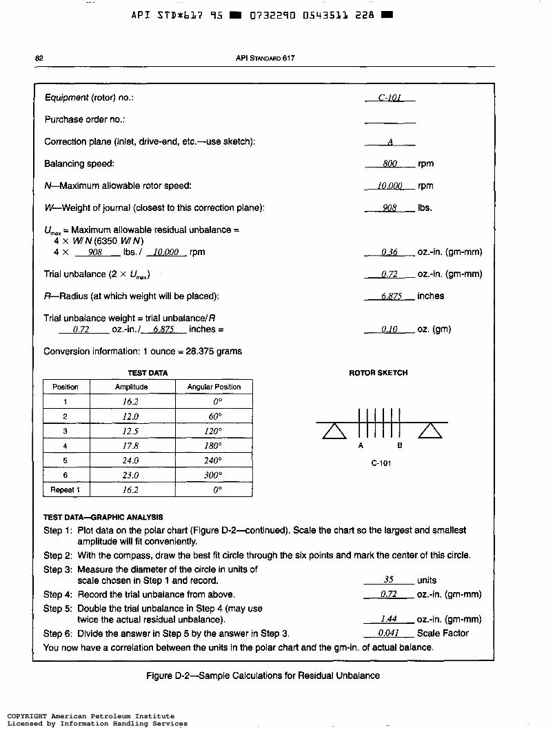
-~
A P I STDUhL7 95 0732290 05435LL 228
82 API STANDARD 617
Equipment (rotor) no.: c-101
Purchase order no.:
Correction plane (inlet, drive-end, etc.-use sketch): A
Balancing speed: 800 rpm
&Maximum allowable rotor speed: 10,000 rpm
W-Weight of journal (closest to this correction plane): 908 Ibs.
U,,,, = Maximum allowable residual unbalance = 4 x W/ N (6350 W/ N ) 4 x 908 lbs./ 10.000 rpm 0.36 oz.-in. (gm-mm)
Trial unbalance (2 X U,,,,,) 0.72 02.4. (gm-mm)
&Radius (at which weight will be placed): 6.875 inches
Trial unbalance weight = trial unbalance/ß 0.72 oz.-in./ 6.875 inches =
Conversion information: 1 ounce = 28.375 grams
TEST DATA
0.10 oz. (gm)
ROTOR SKETCH
A 6
c-101
TEST DATA-GRAPHIC ANALYSIS
Step 1 : Plot data on the polar chart (Figure D-P-continued). Scale the chart so the largest and smallest
Step 2: With the compass, draw the best fit circle through the six points and mark the center of this circle. Step 3: Measure the diameter of the circle in units of
scale chosen in Step 1 and record. 35 units Step 4: Record the trial unbalance from above. Step 5: Double the trial unbalance in Step 4 (may use
Step 6: Divide the answer in Step 5 by the answer in Step 3. You now have a correlation between the units in the polar chart and the gm-in. of actual balance.
amplitude will fit conveniently.
0.72 oz.-in. (gm-mm)
twice the actual residual unbalance). 1.44 oz.-in. (gm-mm) 0.041 Scale Factor
Figure D-P-Sample Calculations for Residual Unbalance
COPYRIGHT American Petroleum InstituteLicensed by Information Handling ServicesCOPYRIGHT American Petroleum InstituteLicensed by Information Handling Services

A P I STD*bL7 95 W 0732290 05435L2 Lbl i
CENTRIFUGAL COMPRESSORS FOR PETROLEUM, CHEMICAL, AND GAS SERVICE INDUSTRIES 83
O"
270"
1 BO0
The circle you have drawn must contain the origin of the polar chart. If it doesn't, the residual unbal- ance of the rotor exceeds the applied test unbalance. Proceed with the balancing machine sensitivity check before rebalancing is attempted.
If the circle does contain the origin of the polar chart, the distance between origin of the chart and the center of your circle is the actual residual unbalance present on the rotor correction plane. Measure the distance in units of scale you choose in Step 1 and multiply this number by the scale factor determined in Step 6. Distance in units of scale between origin and center of the circle times scale factor equals actual residual balance.
Record actual residual unbalance 6.5 (0.041) = 0.27 (oz.-in.)(gm-mm)
Record allowable residual unbalance (from Figure D-2) 0.36 (or.-in.)(gm-mm)
Correction plane A for Rotor No. c-101 @as not) passed.
By 9 1 Date 11 -16-92
Figure D-2-continued
COPYRIGHT American Petroleum InstituteLicensed by Information Handling ServicesCOPYRIGHT American Petroleum InstituteLicensed by Information Handling Services
A P I STD*bL7 95 = O732290 0543533 O T O =
APPENDIX E-ROTOR DYNAMICS LOGIC DIAGRAMS
85
COPYRIGHT American Petroleum InstituteLicensed by Information Handling ServicesCOPYRIGHT American Petroleum InstituteLicensed by Information Handling Services
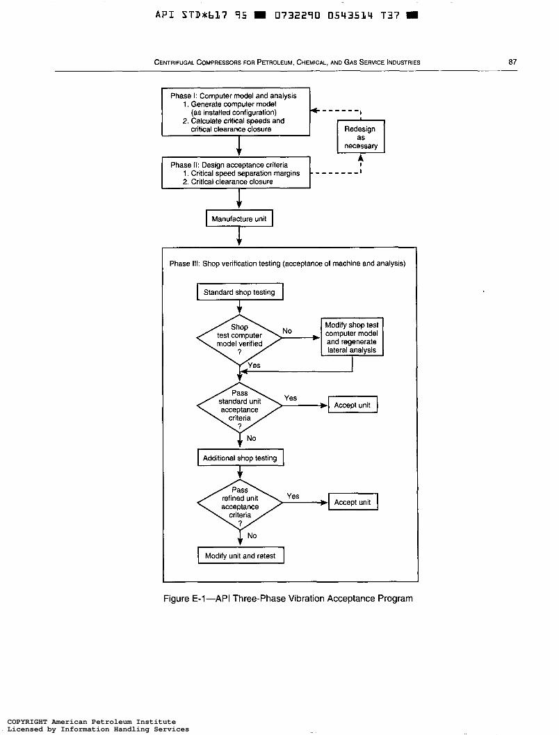
API S T D * b L ï 95 - 0732290 0543534 T37
CENTRIFUGAL COMPRESSORS FOR PETROLEUM, CHEMICAL, AND GAS SERVICE INDUSTRIES 87
Phase I: Computer model and analysis 1. Generate computer model
(as installed configuration) 2. Calculate critical speeds and
critical clearance closure
- - - - - - Redesign
necessary
A
Manufacture unit w ~~ ~ ~~~
Phase 111: Shop verification testing (acceptance of machine and analysis)
Standard shop testing ç=l
acceptance criteria
I Additional shop testing I
acceptance criteria
I Modify unit and retest I
Figure E-1-API Three-phase Vibration Acceptance Program
COPYRIGHT American Petroleum InstituteLicensed by Information Handling ServicesCOPYRIGHT American Petroleum InstituteLicensed by Information Handling Services
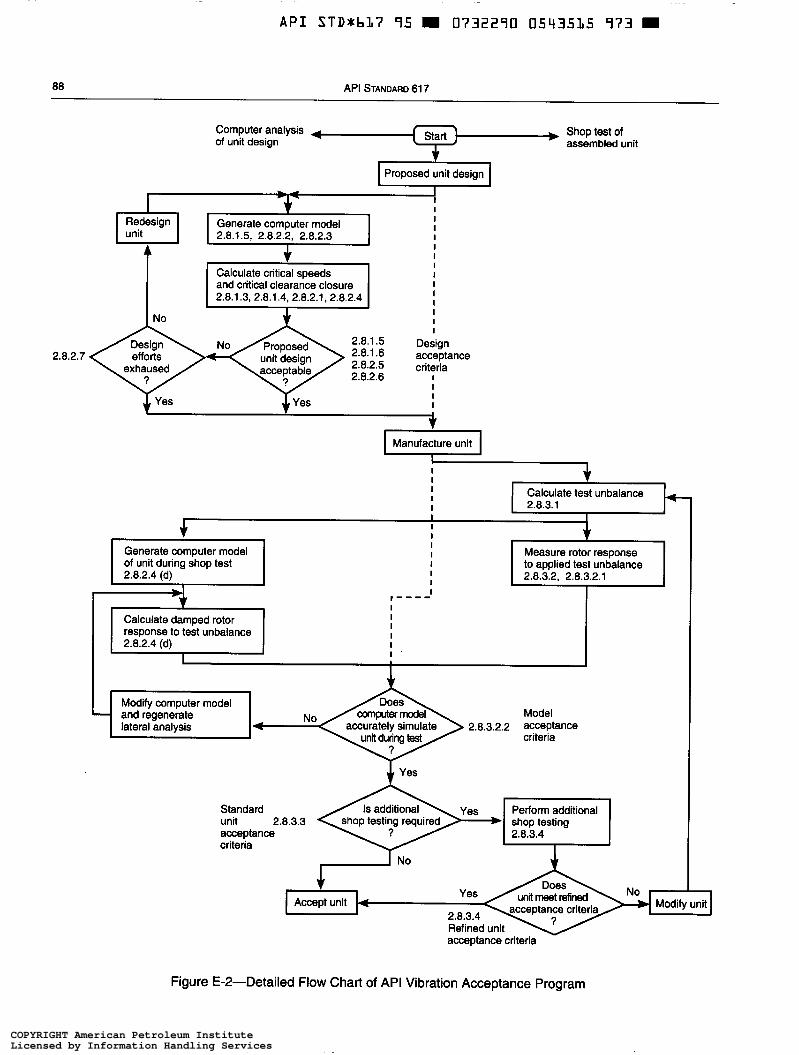
A P I STD*b37 95 m 0732290 0543535 973 m
Generate computer model
2.8.2.4 (d) of unit during shop test
88 API STANDARD 61 7
I
I
I
I Measure rotor response
I 2.8.3.2, 2.8.3.2.1 to applied test unbalance
Shop test of assembled unit
Computer analysis + of unit design
Calculate damped rotor response to test unbalance 2.8.2.4 (d)
Proposed unit design
I M
I I I I
2.8.1.5, 2.8.2.2. 2.8.2.3
and critical clearance closure 2.8.1.3, 2.8.1.4, 2.8.2.1, 2.8.2.4
Design 2.8.1.5 2.8.1.6 2.8.2.5 efforts unit design
2.8.2.7 ~ exhaused acceptable 2.8.2.6
J, Yes J. Yes
I
I I I I I I I I I I I I I I
Design acceptance criteria
I I I I
Manufacture unit Y Calculate test unbalance I 2.8.3.1
I 4:: and Modify regenerate computer model Model
unit during test criteria lateral analysis accurately simulate 2.8.3.2.2 acceptance
Standard Perform additional unit acceptance criteria
acceptance criteria
Figure E-2-Detailed Flow Chart of API Vibration Acceptance Program
COPYRIGHT American Petroleum InstituteLicensed by Information Handling ServicesCOPYRIGHT American Petroleum InstituteLicensed by Information Handling Services
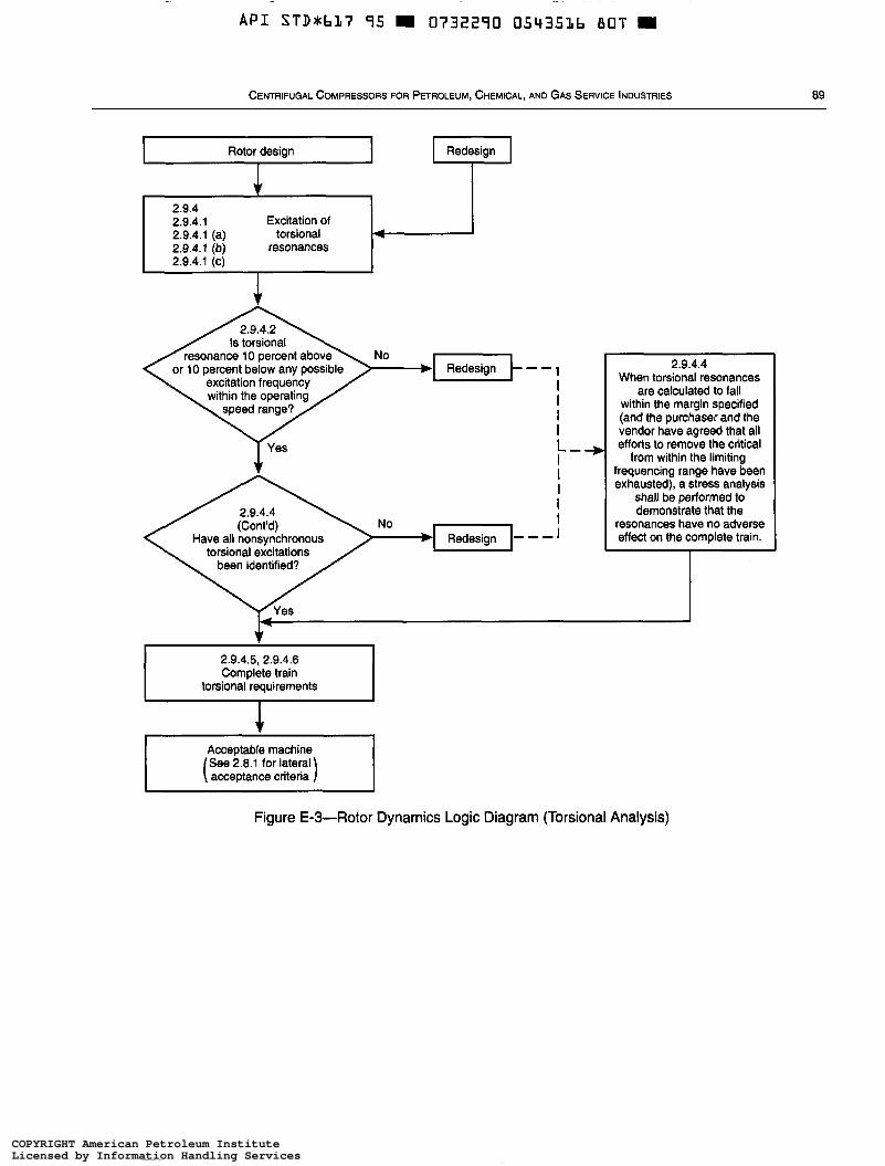
A P I S T D r b 1 7 95 0732290 0543516 B O T
2.9.4 2.9.4.1 Excitation of 2.9.4.1 (a) torsional 2.9.4.1 (b) resonances 2.9.4.1 (c)
CENTRIFUGAL COMPRESSORS FOR PETROLEUM, CHEMICAL, ANO GAS SERVICE INDUSTRIES 89
4
I Rotor design I I Redesign I
bRsdesignk--, No
I I I I L-+ I I I I
))Redesign- - - I No I Have all nonsynchronous
torsional excitations
2.9.4.4 When torsional resonances
are calculated to fall within the margin specified (and the purchaser and the vendor have agreed that all efforts to remove the critical
from within the limiting frequencing range have been exhausted), a stress analysis
shall be performed to demonstrate that the
resonances have no adverse effect on the complete train.
2.9.4.5, 2.9.4.6 Complete train
Acceptable machine See 2.8.1 for lateral
Figure E-3-Rotor Dynamics Logic Diagram (Torsional Analysis)
COPYRIGHT American Petroleum InstituteLicensed by Information Handling ServicesCOPYRIGHT American Petroleum InstituteLicensed by Information Handling Services
~~
A P I STDrb37 95 0732290 0543537 746
APPENDIX F-CENTRIFUGAL COMPRESSOR NOMENCLATURE
91
COPYRIGHT American Petroleum InstituteLicensed by Information Handling ServicesCOPYRIGHT American Petroleum InstituteLicensed by Information Handling Services

A P I STD+bLï 95 0732290 0543514 642 m
CENTRIFUGAL COMPRESSORS FOR PETROLEUM, CHEMICAL, AND GAS SERVICE INDUSTRIES 93
COPYRIGHT American Petroleum InstituteLicensed by Information Handling ServicesCOPYRIGHT American Petroleum InstituteLicensed by Information Handling Services
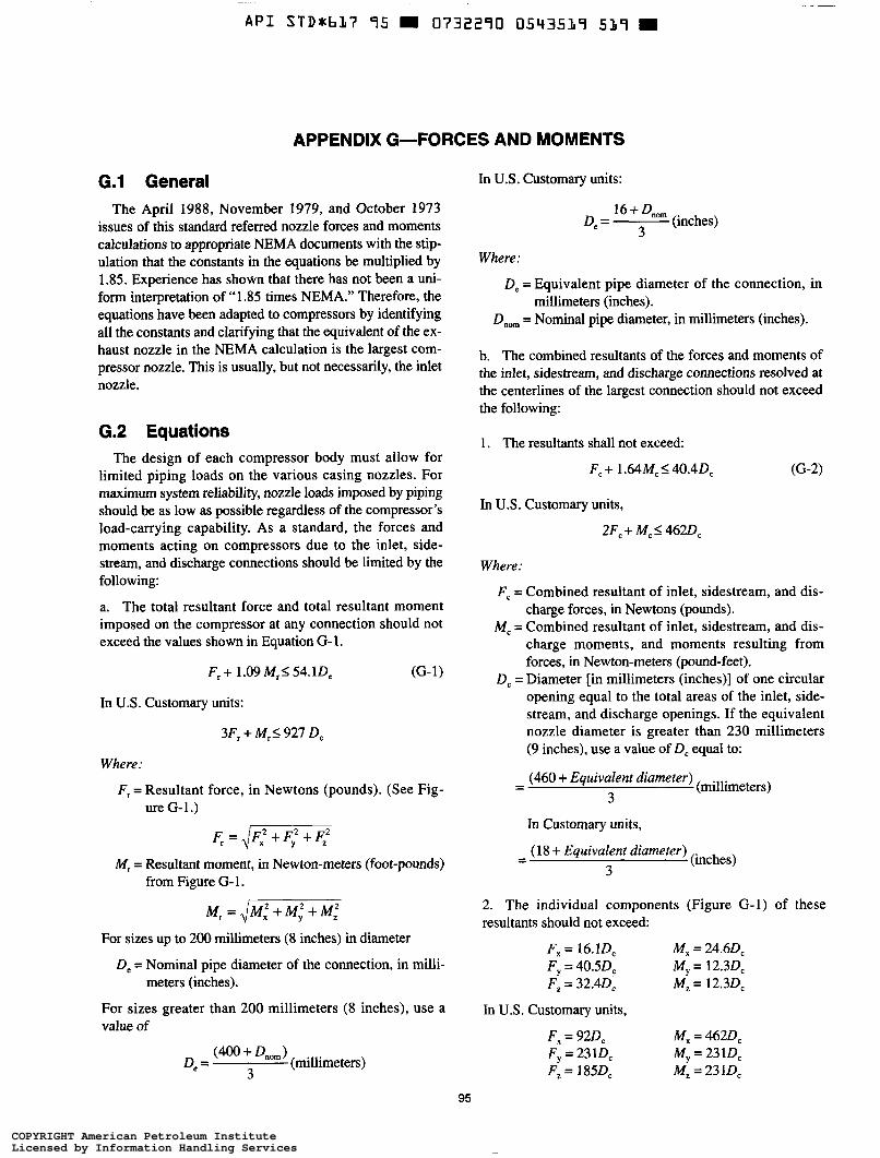
API STD+b17 95 0732290 0543519 519 =
APPENDIX G-FORCES AND MOMENTS
G.l General The April 1988, November 1979, and October 1973
issues of this standard referred nozzle forces and moments calculations to appropriate NEMA documents with the stip- ulation that the constants in the equations be multiplied by 1.85. Experience has shown that there has not been a uni- form interpretation of “1.85 times NEMA.” Therefore, the equations have been adapted to compressors by identifying all the constants and clarifying that the equivalent of the ex- haust nozzle in the NEMA calculation is the largest com- pressor nozzle. This is usually, but not necessarily, the inlet nozzle.
G.2 Equations The design of each compressor body must allow for
limited piping loads on the various casing nozzles. For maximum system reliability, nozzle loads imposed by piping should be as low as possible regardless of the compressor’s load-carrying capability. As a standard, the forces and moments acting on compressors due to the inlet, side- stream, and discharge connections should be limited by the following:
a. The total resultant force and total resultant moment imposed on the compressor at any connection should not exceed the values shown in Equation G-1.
(G- 1) F, + 1 .O9 M, I 54.1 0,
In U.S. Customary units:
3Fr + M,I 927 0,
Where:
F, = Resultant force, in Newtons (pounds). (See Fig- ure G-1.)
M, = Resultant moment, in Newton-meters (foot-pounds) from Figure G- 1.
M, = JM: + ~ y ’ + M ;
For sizes up to 200 millimeters (8 inches) in diameter
0, = Nominal pipe diameter of the connection, in milli-
For sizes greater than 200 millimeters (8 inches), use a value of
meters (inches).
(millimeters) (400 + 4, ) 0, =
3
In U.S. Customary units:
De = 16+ (inches) 3
Where:
De = Equivalent pipe diameter of the connection, in millimeters (inches).
D,,, = Nominal pipe diameter, in millimeters (inches).
b. The combined resultants of the forces and moments of the inlet, sidestream, and discharge connections resolved at the centerlines of the largest connection should not exceed the following:
1. The resultants shall not exceed:
F,+ 1.64Mc5 40.40,
In U.S. Customary units,
2F, + M, I 4620,
Where:
F, = Combined resultant of inlet, sidestream, and dis- charge forces, in Newtons (pounds).
M, = Combined resultant of inlet, sidestream, and dis- charge moments, and moments resulting from forces, in Newton-meters (pound-feet).
0, = Diameter [in millimeters (inches)] of one circular opening equal to the total areas of the inlet, side- stream, and discharge openings. If the equivalent nozzle diameter is greater than 230 millimeters (9 inches), use a value of 0, equal to:
(460 + Equivalent diameter) 3
- - (millimeters)
In Customary units,
(18 + Equivalent diameter) 3
- - (inches)
2. The individual components (Figure G-1) of these resultants should not exceed:
F, = 16.10, F, = 40.50, F, = 32.40,
M, = 24.60, My = 12.30, M, = 12.30,
In U.S. Customary units,
F, = 920, Fy = 2310, F, = 1850,
M, = 4620, My = 2310, M, = 23 lD,
95
COPYRIGHT American Petroleum InstituteLicensed by Information Handling ServicesCOPYRIGHT American Petroleum InstituteLicensed by Information Handling Services
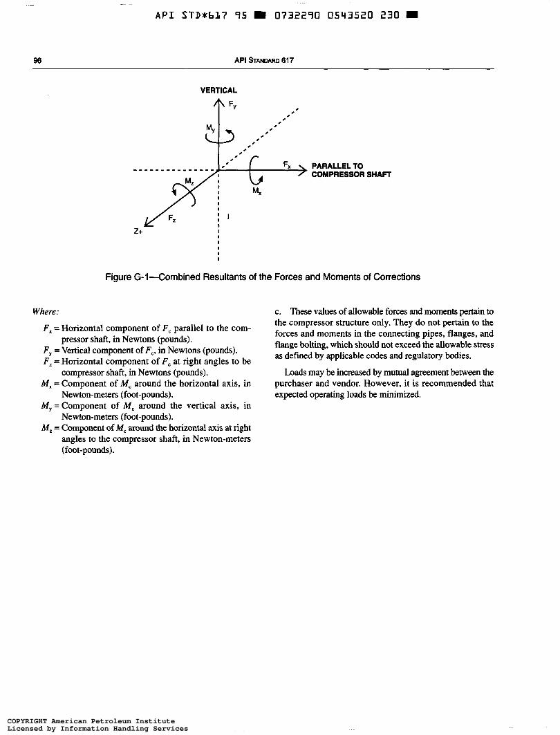
A P I STD*bL7 95 = O732290 0543520 230
96 API STANDARD 61 7
VERTICAL
A FY 0
0 0
0 0
0 0
0 0
0 0
0 0
c 0
0 0
0 Fx PARALLEL TO COMPRESSOR SHAFí
Figure G-I-Combined Resultants of the Forces and Moments of Corrections
Where:
F, = Horizontal component of F, parallel to the com-
F, = Vertical component of F,, in Newtons (pounds). F, = Horizontal component of F, at right angles to be
compressor shaft, in Newtons (pounds). M, = Component of M, around the horizontal axis, in
Newton-meters (foot-pounds). M,=Component of M, around the vertical axis, in
Newton-meters (foot-pounds). M, = Component of M, around the horizontal axis at right
angles to the compressor shaft, in Newton-meters (foot-pounds).
pressor shaft, in Newtons (pounds).
c. These values of allowable forces and moments pertain to the compressor structure only. They do not pertain to the forces and moments in the connecting pipes, flanges, and flange bolting, which should not exceed the allowable stress as defined by applicable codes and regulatory bodies.
Loads may be increased by mutual agreement between the purchaser and vendor. However, it is recommended that expected operating loads be minimized.
COPYRIGHT American Petroleum InstituteLicensed by Information Handling ServicesCOPYRIGHT American Petroleum InstituteLicensed by Information Handling Services
~
API STDlkb17 95 W 0732290 05V3521 1 7 7 =
APPENDIX H-INSPECTOR’S CHECKLIST
97
COPYRIGHT American Petroleum InstituteLicensed by Information Handling ServicesCOPYRIGHT American Petroleum InstituteLicensed by Information Handling Services
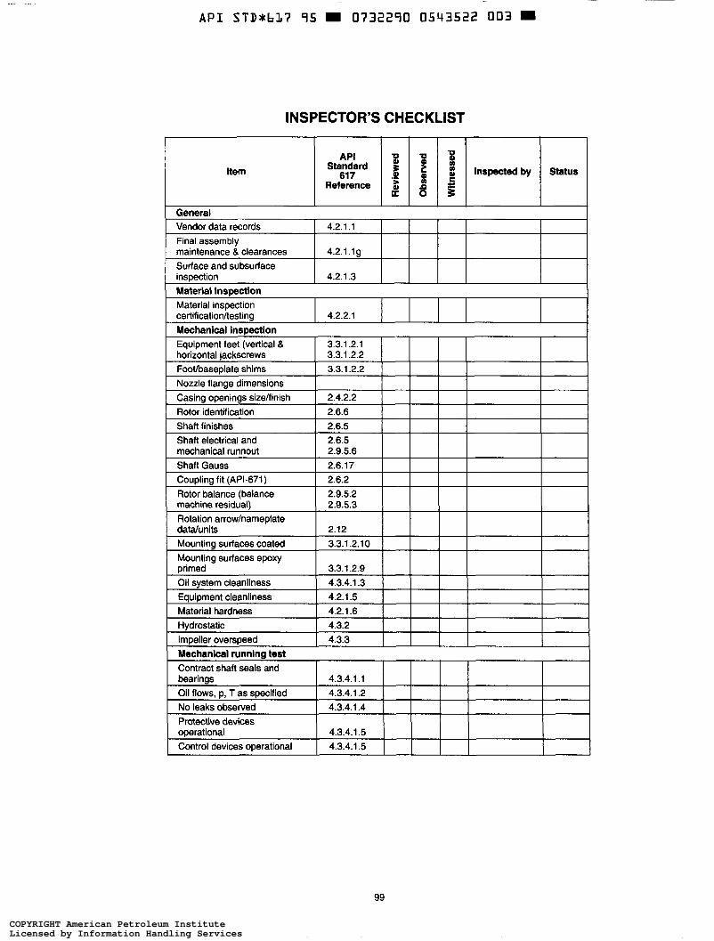
-
A P I S T D * b L ï 95 0732290 0543522 003 9
INSPECTOR’S CHECKLIST
99
COPYRIGHT American Petroleum InstituteLicensed by Information Handling ServicesCOPYRIGHT American Petroleum InstituteLicensed by Information Handling Services
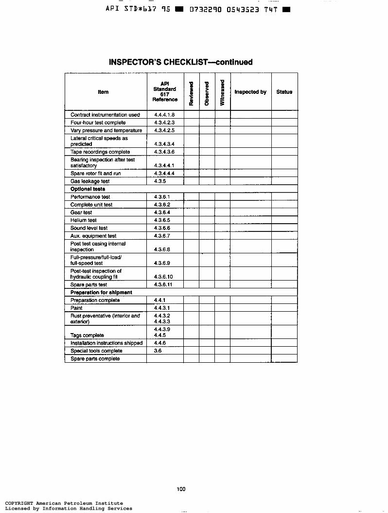
- ~
A P I S T D t b 1 7 95 0732290 0543523 T 4 T
INSPECTOR’S C H EC KLIST-cont i n ued
I API
Contract instrumentation used 4.4.4.1.8 Four-hour test complete 4.3.4.2.3 Varv oressure and temoerature 4.3.4.2.5 Lateral critical speeds as oredicted I 4.3.4.3.4 Tape recordings complete 4.3.4.3.6 Bearing inspection after test satisfactow 4.3.4.4.1
B I
8 % 2 b L >
I 1
Spare rotor fit and run I 4.3.4.4.4 I Gas leakage test I 4.3.5 I Odlonal tests
1 O0
COPYRIGHT American Petroleum InstituteLicensed by Information Handling ServicesCOPYRIGHT American Petroleum InstituteLicensed by Information Handling Services
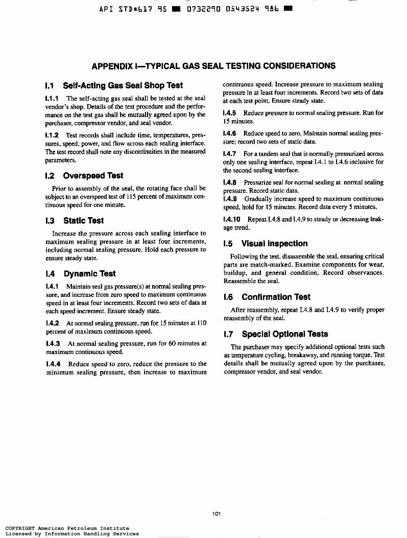
~
A P I S T D * b l t ï 95 0732290 0543524 986
APPENDIX I-TYPICAL GAS SEAL TESTING CONSIDERATIONS
1.1 Self-Acting Gas Seal Shop Test 1.1.1 The self-acting gas seal shall be tested at the seal vendor’s shop. Details of the test procedure and the perfor- mance on the test gas shall be mutually agreed upon by the purchaser, compressor vendor, and seal vendor.
1.1.2 Test records shall include time, temperatures, pres- sures, speed, power, and flow across each sealing interface. The test record shall note any discontinuities in the measured parameters.
1.2 Overspeed Test Prior to assembly of the seal, the rotating face shall be
subject to an overspeed test of 115 percent of maximum con- tinuous speed for one minute.
1.3 Static Test Increase the pressure across each sealing interface to
maximum sealing pressure in at least four increments, including normal sealing pressure. Hold each pressure to ensure steady state.
1.4 Dynamic Test 1.4.1 Maintain seal gas pressure(s) at normal sealing pres- sure, and increase from zero speed to maximum continuous speed in at least four increments. Record two sets of data at each speed increment. Ensure steady state.
1.4.2 At normal sealing pressure, run for 15 minutes at 110 percent of maximum continuous speed.
1.4.3 At normal sealing pressure, run for 60 minutes at maximum continuous speed.
1.4.4 Reduce speed to zero, reduce the pressure to the minimum sealing pressure, then increase to maximum
continuous speed. Increase pressure to maximum sealing pressure in at least four increments. Record two sets of data at each test point. Ensure steady state.
1.4.5 Reduce pressure to normal sealing pressure. Run for 15 minutes.
1.4.6 Reduce speed to zero. Maintain normal sealing pres- sure; record two sets of static data.
1.4.7 For a tandem seal that is normally pressurized across only one sealing interface, repeat 1.4.1 to 1.4.6 inclusive for the second sealing interface.
1.4.8 Pressurize seal for normal sealing at normal sealing pressure. Record static data. 1.4.9 Gradually increase speed to maximum continuous speed, hold for 15 minutes. Record data every 5 minutes.
1.4.10 Repeat 1.4.8 and 1.4.9 to steady or decreasing leak- age trend.
1.5 Visual Inspection Following the test, disassemble the seal, ensuring critical
parts are match-marked. Examine components for wear, buildup, and general condition. Record observances. Reassemble the seal.
1.6 Confirmation Test After reassembly, repeat 1.4.8 and 1.4.9 to verify proper
reassembly of the seal.
1.7 Special Optional Tests The purchaser may specify additional optional tests such
as temperature cycling, breakaway, and running torque. Test details shall be mutually agreed upon by the purchaser, compressor vendor, and seal vendor.
1 o1
COPYRIGHT American Petroleum InstituteLicensed by Information Handling ServicesCOPYRIGHT American Petroleum InstituteLicensed by Information Handling Services
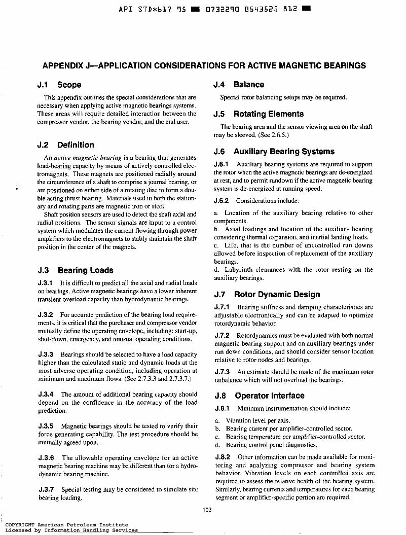
~
API STDrbl17 95 W 0732290 0543525 812 m
J.l Scope This appendix outlines the special considerations that are
necessary when applying active magnetic bearings systems. These areas will require detailed interaction between the compressor vendor, the bearing vendor, and the end user.
J.2 Definition An active magnetic bearing is a bearing that generates
load-bearing capacity by means of actively controlled elec- tromagnets. These magnets are positioned radially around the circumference of a shaft to comprise a journal bearing, or are positioned on either side of a rotating disc to form a dou- ble acting thrust bearing. Materials used in both the station- ary and rotating parts are magnetic iron or steel.
Shaft position sensors are used to detect the shaft axial and radial positions. The sensor signals are input to a control system which modulates the current flowing through power amplifiers to the electromagnets to stably maintain the shaft position in the center of the magnets.
J.3 Bearing Loads 5.3.1 It is difficult to predict all the axial and radial loads on bearings. Active magnetic bearings have a lower inherent transient overload capacity than.hydrodynamic bearings.
5.3.2 For accurate prediction of the bearing load require- ments, it is critical that the purchaser and compressor vendor mutually define the operating envelope, including: start-up, shut-down, emergency, and unusual operating conditions.
J.3.3 Bearings should be selected to have a load capacity higher than the calculated static and dynamic loads at the most adverse operating condition, including operation at minimum and maximum flows. (See 2.7.3.3 and 2.7.3.7.)
5.3.4 The amount of additional bearing capacity should depend on the confidence in the accuracy of the load prediction.
5,3.5 Magnetic bearings should be tested to verify their force generating capability. The test procedure should be mutually agreed upon.
5.3.6 The allowable operating envelope for an active magnetic bearing machine may be different than for a hydro- dynamic bearing machine.
J.3.7 bearing loading.
Special testing may be considered to simulate site
J.4 Balance Special rotor balancing setups may be required.
5.5 Rotating Elements The bearing area and the sensor viewing area on the shaft
may be sleeved. (See 2.6.5.)
J.6 Auxiliary Bearing Systems 5.6.1 Auxiliary bearing systems are required to support the rotor when the active magnetic bearings are de-energized at rest, and to permit rundown if the active magnetic bearing system is de-energized at running speed.
5.6.2 Considerations include:
a. Location of the auxiliary bearing relative to other components. b. Axial loadings and location of the auxiliary bearing considering thermal expansion, and inertial landing loads. c. Life, that is the number of uncontrolled run downs allowed before inspection of replacement of the auxiliary bearings. d. Labyrinth clearances with the rotor resting on the auxiliary bearings.
J.7 Rotor Dynamic Design J.7.1 Bearing stiffness and damping characteristics are adjustable electronically and can be adapted to optimize rotordynamic behavior.
J.7.2 Rotordynamics must be evaluated with both normal magnetic bearing support and on auxiliary bearings under run down conditions, and should consider sensor location relative to rotor nodes and bearings.
5.7.3 unbalance which will not overload the bearings.
An estimate should be made of the maximum rotor
J.8 Operator Interface 5.8.1 Minimum instrumentation should include:
a. Vibration level per axis. b. Bearing current per amplifier-controlled sector. c. Bearing temperature per amplifier-controlled sector. d. Bearing control panel diagnostics.
5.8.2 Other information can be made available for moni- toring and analyzing compressor and bearing system behavior. Vibration levels on each controlled axis are required to assess the relative health of the bearing system. Similarly, bearing currents and temperatures for each bearing segment or amplifier-specific portion are required.
103
COPYRIGHT American Petroleum InstituteLicensed by Information Handling ServicesCOPYRIGHT American Petroleum InstituteLicensed by Information Handling Services
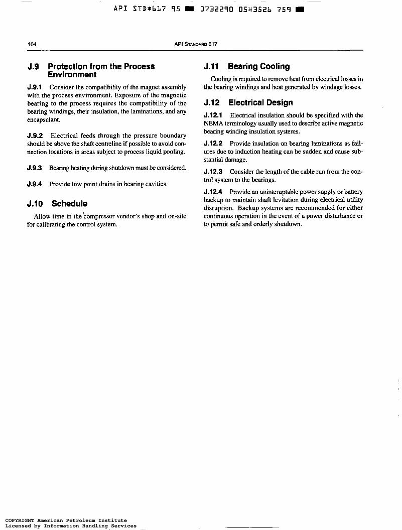
~~
API STDrbL7 95 m 0732290 0543526 759 =
104 API STANDARD 617
J.9 Protection from the Process Environment
J.9.1 Consider the compatibility of the magnet assembly with the process environment. Exposure of the magnetic bearing to the process requires the compatibility of the bearing windings, their insulation, the laminations, and any encapsulant.
J.9.2 Electrical feeds through the pressure boundary should be above the shaft centreline if possible to avoid con- nection locations in areas subject to process liquid pooling.
J.9.3 Bearing heating during shutdown must be considered.
J.9.4 Provide low point drains in bearing cavities.
J.10 Schedule Allow time in the *compressor vendor?s shop and on-site
for calibrating the control system.
J.11 Bearing Cooling Cooling is required to remove heat from electrical losses in
the bearing windings and heat generated by windage losses.
5.12 Electrical Design 5.12.1 Electrical insulation should be specified with the NEMA terminology usually used to describe active magnetic bearing winding insulation systems.
5.12.2 Provide insulation on bearing laminations as fail- ures due to induction heating can be sudden and cause sub- stantial damage.
5.12.3 Consider the length of the cable run from the con- trol system to the bearings.
J.12.4 Provide an uninteruptable power supply or battery backup to maintain shaft levitation during electrical utility disruption. Backup systems are recommended for either continuous operation in the event of a power disturbance or to permit safe and orderly shutdown.
COPYRIGHT American Petroleum InstituteLicensed by Information Handling ServicesCOPYRIGHT American Petroleum InstituteLicensed by Information Handling Services

A P I STDabL7 95 0732790 0543527 695
1-01400-2/95-1.5M (4E)
COPYRIGHT American Petroleum InstituteLicensed by Information Handling ServicesCOPYRIGHT American Petroleum InstituteLicensed by Information Handling Services
~~
API STDabL7 95 m 0732290 0543528 52% m
American Petroleum Institute 1220 L Street, Northwest
Order No. 822-61706
COPYRIGHT American Petroleum InstituteLicensed by Information Handling ServicesCOPYRIGHT American Petroleum InstituteLicensed by Information Handling Services