API 2550 Meas and Calib (R1992)
60
I- STD 2550-65 I 0732290 Method for Measurement and Calibration of Upright Cylindrical Tanks API STANDARD 2550 FIRST EDITION, OCTOBER 1965 @ American Petroleum Institute API Standard 2550 f#b American Society for Testing & Materials ASTM D 1220 I L W American National Standards Institute ANSVASTM D 1220 I 0067561 h r 09-(3 I American Petroleum Institute 2101 L Street. Northwest 4’ Washington, D.C. 20037 No reproduction or networking permitted without license from IHS --`,,,`,,,```,,```,``,`,,,`,`,`-`-`,,`,,`,`,,`---
-
Upload
dagoype6844 -
Category
Documents
-
view
2.386 -
download
90
Transcript of API 2550 Meas and Calib (R1992)

I-
S T D 2550-65 I 0732290
Method for Measurement and Calibration of Upright Cylindrical Tanks
API STANDARD 2550 FIRST EDITION, OCTOBER 1965
@ American Petroleum Institute API Standard 2550
f#b American Society for Testing & Materials ASTM D 1220
I L W American National Standards Institute ANSVASTM D 1220 I
0067561 h r
09-(3 I
American Petroleum Institute 2101 L Street. Northwest
4’ Washington, D.C. 20037
Copyright American Petroleum Institute Provided by IHS under license with API Licensee=Aramco HQ/9980755100
Not for Resale, 11/25/2006 02:32:33 MSTNo reproduction or networking permitted without license from IHS
--`,,,`,,,```,,```,``,`,,,`,`,`-`-`,,`,,`,`,,`---

Method for Measurement and Calibration of Upright Cylindrical Tanks
Measurement Coordination/lndustry Affairs
API STANDARD 2550 FIRST EDITION, OCTOBER 1965
American Petroleum Institute
Copyright American Petroleum Institute Provided by IHS under license with API Licensee=Aramco HQ/9980755100
Not for Resale, 11/25/2006 02:32:33 MSTNo reproduction or networking permitted without license from IHS
--`,,,`,,,```,,```,``,`,,,`,`,`-`-`,,`,,`,`,,`---
ANSI STANDARD
An ANSI Standard implies a consensus of those substantially concerned with its scope and provisions. An ANSI Standard is intended as a guide to aid the manu- facturer, the consumer, and the general public. The existence of an ANSI Standard does not in any respect preclude anyone, whether he has approved the standard or not, from manufacturing, marketing, purchasing, or using products, processes, or procedures not conforming to the standard. ANSI Standards are subject to periodic review and users are cautioned to obtain the latest editions. Producers of goods made in conformity with an ANSI Standard are encouraged to state on their own responsibility in advertising, promotion material, or on tags or labels that the goods are produced in conformity with particular ANSI Standards.
This ANSI Standard is one of nearly 4,000 standards approved as USA Standards by the United States of America Standards Institute. In October 1969, the USAS1 was reconstituted as the American National Standards Institute. Standards approved as USA Standards are now designated ANSI Standards. There is no change in their index identification or technical content.
NOTE: API Standard 2550-ASTM D 1220 was approved as an ANSI Standard Dec. 30, 1966.
Copyright American Petroleum Institute Provided by IHS under license with API Licensee=Aramco HQ/9980755100
Not for Resale, 11/25/2006 02:32:33 MSTNo reproduction or networking permitted without license from IHS
--`,,,`,,,```,,```,``,`,,,`,`,`-`-`,,`,,`,`,,`---
, - STD 2550-b5
FOREWORD
The standard in this publication is one of a series approved jointly by the American Petroleum Institute and the American Society for Testing and Materials. This standard is the result of a cooperative arrangement established by the two organizations to develop and jointly approve and publish standards dealing with quantitative and qualitative measurements of petroleum products and lubricants.
T h e American Petroleum Institute and the American Society for Testing and Materials take no position as to whether any method, apparatus, or product mentioned herein is covered by an existing patent, nor as to the validity of any patent alleged to cover any such method, apparatus, or product. Furthermore, the information contained in this standard does not grant the right, by implication or otherwise, for manufacture, sale, or use in connection with any method, apparatus, or product covered by letters patent; nor does it insure anyone against liability for infringement of letters patent.
This standard may be used by anyone desiring to do so, but neither the American Petroleum Institute nor the American Society for Testing and Materiais shall be held responsible or liable in any way either for loss or damage resulting therefrom, or for the violation of any federal, state, or municipal regulations with which it may conflict.
Suggested revisions are invited and should be submitted to the Measurement Coordinator, American Petroleum Institute, 2101 L Street, N.W., Washington, DC 20037.
Copyright American Petroleum Institute Provided by IHS under license with API Licensee=Aramco HQ/9980755100
Not for Resale, 11/25/2006 02:32:33 MSTNo reproduction or networking permitted without license from IHS
--`,,,`,,,```,,```,``,`,,,`,`,`-`-`,,`,,`,`,,`---

S T D 2550-65 1 0732290 0067565
CONTENTS PAQE
....................... 7 Definitions. . . . . . . . . . . . . . . . . . . . . . . . . . . . . . . . . . . . . . . . . ....................... 7 Significance. . . . . . . . . . . . . . . . . . . . . . . . . . . . . . . . . . . . . . . . . . . . . . . . . . . . . . . . . . . . . . . . . . . . . 7 Tank-Measuring Equipment and Its Calibration. . . . . . . . . . . , . . . . , . . . . . . . . . . . . . . . . 8 Measuring Tapes.. . . . . . . . . . . . . . . . . . . . .. . . . . . . . . . . . . . . . . . . . . . . . . . . . . . . . . . . . . . . . . . 8 Accessory Equipme . . . . . . . . . . . . . . . . . . . . . . . . . . . . . . . . . . . . . . . . . . . . . . . . . . . . . . . . . . 8 General Practices. . . . . . . . . . . . . . . . . . . . . . . . . . . . . . . . . . . . . . . . . . . ... . . . . . . ... . . . . . 11
Conditions f Disputes.. . .
Scope. . . . . . . . . . . . . . . . . . . . . . . . . . . . . . . . . . . . . . . . . . . . . .
PART I. MEASUREMENT PROCEDURES
. . . . . . . .. 12
12 . . . . . . . . . , . . . . . .
ture . . . . . . . . . . . . . . . . . . . . . . . . . . . . . . . . . . . . . . . . . . . . . . . . . . . . . . . . . . . . . . . . . . . . . . . . . . 12 Effect of Ti l t on Cylindrical Tank Shell Recalibration of Weld 12 Tolerances. . . . . . . . . . . . . . . . . . . . . . . . . . . 13 Shell Plate Thickness . . . . . . . . . . . . . . . . . . . . . . . . . . . 13 Vertical Tank Measurements.. . . . . . . . . . . . . . . . . . . . . . . . . . . . . . . . . . . . . . . . . . . . . . . . . . . 13
. 14
. 15
. 29
. . . . . . . . . . . . . . . .
Preparations for Circumferential Measurements. . . . , . . . . . . . . . . . . . . . . . . . . .-. . . . Circumferential Measurements. . . . . . . . . . . . . . . . . . . . . . . . . . . . . . . . . . . . . . . . . . . . . . Deadwood . . , . . . . . . . . . . . . . . . . . . , . . . . . . . . . . . . . . . . . . . . . . . . . . . . . . . . . . . . . . . . . . . .
Tank Bottoms. . . . . . . . . . . . . . . . . . . . . . . . . . . . . . . . . . . . . . . . . . . . . . . . . . . . . . . . Tank Bottoms-Flat T pe . . . . . . . . . . . . . . . . . . . . . . . . . . . . . . . . . . . . . . . . . . . . . . Tank Bottom-Conical, Hemispherical
Tank Roofs Other Than Fixed Roofs.. . . . . . . Floating Roofs.. . . . . . . . . . . . Measurement Procedure for Variable Volume Roofs.. . . .
Wooden Tanks . . . . . . . . . . . . . . . . . . . . . . . . . . . . . . _ . . . . . . . . . . . . . . . General. . . . . . . . . . . . . . . . . . . . . . . . . . . . . . . . . . . . . . . . . . . . . . . . . . . . . . . . . . . . . . . . . . . . . . . Terminology. . . . . . . . . . . . . . . . . . . . . . . . . . . . . . . . . . . . . , . . . . . . . . . . . . . . . . . . . . . . . . . . . .
nd Spherical Segmen
..........................
. 29
. 29 . 32
. 32
. 32
. 32 . 37
. 38
. 38
. . . . . . . . . . . . . . . .
. . . . . . . . . .
Underground Tanks. . . . . . . . . . . . . . . . . . . . . . , . , . . . . . . . . . . . . . . . . . . . . . . . . . . . . . . . . . . . . . . Conditions and Procedures for Measurements. . . . . . . . . . . . . . . . . . . . . . . . . . . . . . . . . . . .
Significant Figures. . . . . . Interpolations . . . . . . . . . .
Disregarded Tank Volume. . . . . . . . . . Deductions for Circumference Tape . . . . . . . . . . . . . . . . . . . . . . . . . . . . Expansion and Contraction of Steel Expansion and Contraction of Steel Effect of Tilt on Cylindrical Portion of Tank. . . . . , . . . . . . . . . . . . . . . . . . . . . . . . . . . . . . Effect of Out-of-Round Condition. , . . . . . . . . . . . , . . . . . . . . . . . . . . . . . . . . . . . . . . . . . . . . .
Variable Volume Roofs.. . . . . . . . . . . . . . . . . . . . . APPENDIX I-Example of Calculations for Upri
APPENDIX II-Constants, Equations, Conversion Factors, and Tables.. . . . . . . . .
. . . . . . . . . . . . . . . . . . . . . . . . . . . . . . . . . . . . . . . .
Floating Roofs and Variable Volume Roofs.. . . . . . . . . . . . . . . . . . . . . . . . . . . . . . Floating Roofs.. . . . . . . . . . . . . . . . . . . . . . . . . . . . . . . . . . . . . . . . . . . . . . . . . . . . . . . . .
.................... Steel Tank-Above-
ground. . . . . . . . . . . . . . . . . . . . . . . . . . . . . . . . . , . . . . . . . . . . . . . . . . . . . . . . . . . . . . . . . . . . .
38 38 39 39 39 39 40 40 40 40 42 42 42 43 43
43 43 43 43 43 43 43 43 44 44 44 44 44 45 45 46 46 46 47
48 57
Copyright American Petroleum Institute Provided by IHS under license with API Licensee=Aramco HQ/9980755100
Not for Resale, 11/25/2006 02:32:33 MSTNo reproduction or networking permitted without license from IHS
--`,,,`,,,```,,```,``,`,,,`,`,`-`-`,,`,,`,`,,`---

S T D 2550-65 0732290 O067566 5 r
Stalzdard Method for
MEASUREMENT AND CALIBRATION OF UPRIGHT CYLINDRICAL TANKSi
API Standard: 2550 .
ASTM Designatiop: D 1220 - 65 ADOPTED, 1965.‘J
This standard of the American Petroleum Institute issued under the fixed designation API 25.50 is also a standard of the American Society for Testing and Materials issued under the fixed designation D 1220; the h a 1 number indicates the year of original adoption as standard, or, in the case of revision, the year of last revision.
This method was adopted as a j h t API-ASTM Standard in 1965.
Scope 1. This standard describes the proce-
dures for calibrating upright cylindrical tanks larger than a barrel or drum. It is Tesented in two parts: Part I (Sections
to 41) outlines procedures for making necessary measurements to determine to- tal and incremental tank volumes; Part II (Sections 42 to 58) presents the recom- mended procedure for computing vol- umes.
NOTE 1.-Other calibration standards are: API Standard 2661-ASTM D 1410: Meas-
urement- and Calibration of Horizontal Tanks
1 Under the standardization procedures of the API and the ASTM, this standard is under the jurisdiction of the API Central Committee on Petroleum Measurement and the ASTM Committee D-2 on Petroleum Products and Lubricants.
2The API method was adopted as API Standard 2550 in October, 1965.
Prior to their present publication, the API methods of test were issued in December, 1929 as API Code 25. API Code 25 was reissued in 1930, 1931, 1933, 1935, 1940, and 1948. The material was revised and reissued in September, 1955 as API Standard 2501, and the second edi- tion was issued in July, 1961.
8 Revised and adopted as standard June, 1965 by action of the ASTM at the Annual Meeting and confirming letter ballot.
Prior to adoption aa ASTM standard, this method was published as tentative from 1952 to 1959, being revised in 1955,1956,1957,1958, and ’459.
API Standard 2662-ASTM D 1408: Meas- urement and Calibration of Spheres and Spheroids
API Standard 2663-ASTM D l4ûY: Meas- urement and Calibratioz of Barges
API Standard 2664-ASTM D1409: Meas- urement and Calibration of Tank Cars
API Standard 2666-ASTM D 1406: Liquid Calibration of Tanks
Definitions
2. (a) “Tank strapping” is the term commonly applied to the procedure for the measurement of tanks to provide the dimensions necessary for the computation of gage tables. These tables will show the quantity of oil in a tank at any given depth.
( b ) Tank strapping includes the fol- lowing measurements:
(1) Depth.4hel i height, oil height, ring height, equalizer line height, and gag- ing height.
(2) Thickness of Tank WaUs.-Stave thickness and metal thickness.
(S) Circumferences of Tank at Speci- fied Locations.
(4 ) Deadwood.-Any object within the tank, including a floating roof, which dis- places liquid and reduces the capacity of the tank; also any permanent appurte- nances on the outside of the tank, such
7
as cleanout boxes or manholes, which in- crease the capacity of the tank.
Significance
3. Accurate tank measurements are 8
most important factor in liquid volume de- terminations, for the reason that an incor- rect dimension results in an erroneous gage table, which might be in use over an ex- tended period of time before the error is discovered. In most cases, the person who computes the gage tables is not the one making the actual field measurements and has no direct means of checking such measurements; therefore, this person must depend upon the tank strapper for ac- curate measurements. Errors in gage ta- bles cause the accounting of tank contents to be inaccurate; therefore, payments are subject to question. Settlements involving such errors are very difficult, and some- times impossible, to adjust without loss to one of the parties involved. As the pro- cedure for taking measurements and the achievement of accuracy in tank strapping are so important, ail such measurements should be witnessed by all parties inter- ested in the subsequent measurement of quantities in the tanks being strapped. It is hoped that the foregoing wiii provide an adequate idea of the extreme impor- tance of correctness in this particular de- tail.
Copyright American Petroleum Institute Provided by IHS under license with API Licensee=Aramco HQ/9980755100
Not for Resale, 11/25/2006 02:32:33 MSTNo reproduction or networking permitted without license from IHS
--`,,,`,,,```,,```,``,`,,,`,`,`-`-`,,`,,`,`,,`---
S T D 2550-65 0732240 0067567 7 r (API 2550 - ASTM D 1220) 8 MEASUREMENT AND CALIBRATION OF UPRIGHT CYLINDRICAL TANKS
Tank-Measuring Equipment and Its Cali- bration 4. The equipment to be used for tank
measurements is covered in Sections 5 and 6. The measurement of any one tank will not require the use of all the equipment listed. Therefore, the type of tank and the proper calibration procedure must be considered carefully before selecting the equipment needed. All equipment shail be in good condition. All tapes shall be in one piece (unmended) and free of kinks.
Measuring Tapes 5. (a) Tapes for Height Measurements.
-For height measurements, a steel tape, Fig. l ( a ) , of convenient length, s/s or ‘/2 in. wide and 0.008 to 0.012 in. thick-grad- uated in feet and inches to eighths of an inch, or in feet, tenths, and hundredths of a foot-is recommended. The working tape shall be calibrated against a “stand- ard” tape in a vertical position, with equal tension (1 to 2 Ib) applied to both. Gradu- ations shall be accurate within %z in. or 0.05 f t throughout that portion of the tape length to be used.
(b) Tapes for Circumference Measure- ments.-For circumference measurements, a steel tape, Fig. l ( b ) , of convenient length relative to the tank circumference, usually 100, 200, 300, 500, or 600 f t in length, is recommended. The working tape should not be more than ‘/4 in. wide, and approximately 0.01 in. thick. The tape may be graduated in feet, with an extra 1-ft length a t the zero end graduated in tenths and hundredths of a foot, or it may be graduated in feet, tenths, and hundredths of a foot throughout its length. The tape shall be calibrated (for required tension) by matching it against the stand- ard tape in the following manner: Choose a convenient tape path on the lower ring and place the standard tape around the tank by the successive tangent method with constant application of tension as near as possible to that at which the standard tape was certified to be accurate, scoring the tank a t each 100 ft or fraction thereof. Total the measurements thus ob- tained and place the working tape around the tank, using the same tape path, by the continuous “wraparound” procedure ; slide the working tape to break frictional resistance; and apply tension sufficient to equal the measurement obtained with the standard tape. The amount of tension, in pounds, required to’be placed on the work-
ing tape to obtain the same measurement as that recorded with the standard tape shall be applied to the working tape when taking circumferential measurements. If the tension determined to be proper for the working tape is insufficient to hold the tape in the proper position, additional tension should be applied and a correction made to bring the reading into agreement with that obtained with the standard tape. The amount of correction should not ex- ceed 0.01 ft (approximately %2 in.) for each 100 ft of tape in use. In making “critical measurements,” this procedure shall be carried out for each tank of differ- ent diameter where the circumference di€- fers by more than 20 per cent from the calibrated tape section, and where tank surfaces are different. It should be noted that circumference measurements may be made with working tapes which have been calibrated by a standard tape of length based on 68 F.
If the preceding calibration procedure is not practicable, a suitable flat, hori- zontal surface, such as a railroad rail, may be substituted for the tank shell surface. In either case, if two or’more successive check readings are taken, the supporting surface frictional resistance to movement of the working tape should be broken be- tween such successive readings.
(c) Tape Calibration,-The standard tape for calibrating tank-measuring (working) tapes shall be identiñed with a Reportgof Calibration a t 68 F by the National Bureau of Standards attesting to the standard tape accuracy within 0.001 f t (approximately %4 in.) per i00 ft of length. The Report of Calibration for a standard tape shall include these factors and/or formulas necessary to cor- rect the tape length for use:
(i) At60F. (2) Under tension differing from that
used in calibration, (3) Under conditions of sag in an un-
supported tape. (d ) Reek-Tapes shall be equipped
with appropriate reels and handles. (e) Tape Clamps.-For assurance of
positive grip on tape, clamps shall be used.
NOTE 2.-The National Bureau of Stand- ards provides for standard tapes (NBS “ref- erence)’ tapes) only a Report of Calibra- tion at 68 F when the tape is completely supported in a horizontal position and mb- ject to horizontal tension 89 prescribed in
National Bureau of Standards Test Fee Schedule 202..$04-Steel Tapes. The ad{ tional data indicated in Section 5(c), Iter\ ( I ) , (d ) , and ( 9 ) ) are included in the NB6 Report of Calibration only when requested by the applicant and to the extent specifi- cally requested.
Accessory Equipment 6. (a) Additional measuring equipment
recommended is described in Paragraphs (b) to (m) and shown in Fig. l (c ) to (h) and Figs, 2, 3, and 4. Other similar equip- ment may be used, provided that it will give the same results,
(b) Rope, %-in. Manila hemp, but not less than % in., of a length approximately equal to four times the tank height. Block and tackle to be one single block with loose hook and becket and one double block with loose hook. Blocks to have hardwood shells about 8 in. long with sheaves for %-in. or larger rope.
NOTE 3.-Blocks suitable for larger rope than required will provide an ample factor of safety and take care of swelling of Manila rope due to dampness.
(c) Seat, of oak or white pine board 1% to 2 in, thick, 30 in. long, and 10 in. wide; dressed; and with holes for ropeP drilled near each corner, top and botta edges of holes slightly rounded; %- or %- in,-diameter rope passed through holes, ends splicid and wrapped together on each side above the board with short pieces of small rope.
(d ) Water Curtain Hook for fastening block and tackle to the top of the tank, %-in.-diameter steel, and bent to shape; each end welded into an eye suitable for receiving the hook of the double block; and fastened to spray or other fixed point on top of the tank with 1-in. Manila hemp rope.
(e) Special Hook for Open-Top Tanks, Ya by 3 in., flat, bent to shape, and with hole in end suitable for receiving the hook of the double block.
(f) Sajetg Belts, two required, heavy canvas webbing with double buckles, leather shoulder straps for fastening, steel ring a t crosimg of straps in back to which ropes are fastened with a splice. Rope to be ‘/2-in. Manila hemp,
( 8 ) Rope and Ring,-Two lengths of rope line fitted with snap and ring to be used in raising and lowering circumfer- ence measurement tape. Aiternativel~ jointed-type pole guides may be used.
(h ) Depth Gage.-Depth gage of case-
Copyright American Petroleum Institute Provided by IHS under license with API Licensee=Aramco HQ/9980755100
Not for Resale, 11/25/2006 02:32:33 MSTNo reproduction or networking permitted without license from IHS
--`,,,`,,,```,,```,``,`,,,`,`,`-`-`,,`,,`,`,,`---
S T D 2550-65 0732290 0067568 ïr MEASUREMENT AND CALIBRATION OF UPRIGHT CYLINDRICAL TANKS (API 2550 - ASTM D 1220) 9
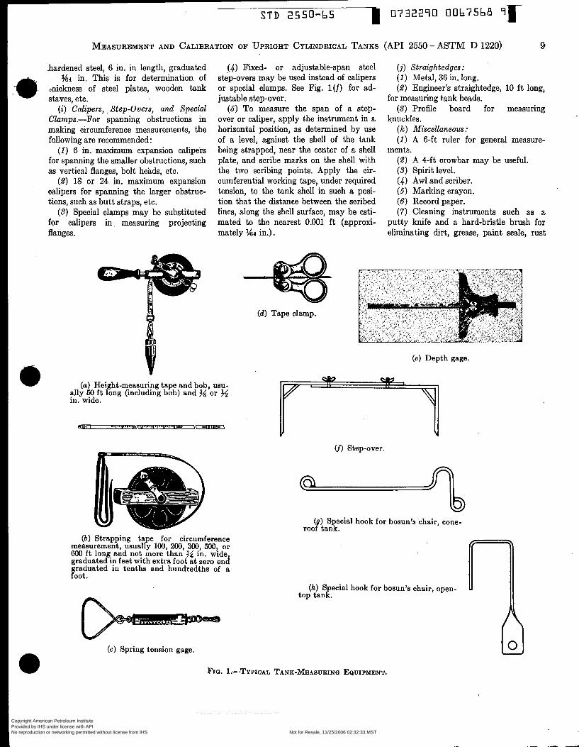
-a hardened steel, 6 in. in length, graduated
%4 in. This is for determination of &hess of steel plates, wooden tank staves, etc.
(i) Calipers, . Step-Overs, and Special Clamps.-For spanning obstructions in making circumference measurements, the foilowing are recommended :
(i) 6 in. maximum expansion calipers for spanning the smaller obstructions, such as vertical flanges, bolt heads, etc.
(2 ) 18 or 24 in. maximum expansion calipers for spanning the larger obstruc- tions, such as butt straps, etc.
(3) Special clamps may be substituted for calipers in measuring projecting flanges.
(4) Fixed- or adjustable-span steel step-overs may be used instead of calipers or special clamps. See Fig. l(f) for ad- justable step-over.
(5 ) To measure the span of a step- over or caliper, apply the instrument in a horizontal position, as determined by use of a level, against the sheìl of the tank being strapped, near the center of a shell plate, and scribe marks on the sheil with the two scribing points. Apply the cir- cumferential working tape, under required tension, to the tank shell in such a posi- tion that the distance between the scribed lines, along the sheil surface, may be esti- mated to the nearest 0.001 f t (approxi- mately %4 in.).
(i) Straightedges .- (i) Metal, 36 in. long. (2 ) Engineer's straightedge, 10 f t long,
for measuring tank heads. (3) Profile board for measuring
knuckles. (k) Miscellaneous: (i) A 6-ft ruler for general measure-
( 2 ) A 4-ft crowbar may be useful. ( 3 ) Spirit level. (4) Awl and scriber. (5 ) Marking crayon. (6) Record paper. (7) Cleaning instruments such as a
putty knife and a hard-bristle brush for eliminating dirt, grease, paint scale, rust
ments.
_.--
( d ) Tape clamp.
(a) Height-measuring tape and bob, usu- ally 50 f t long (including bob) and % or in. wide.
(a) Strapping tape for circumference measurement, usually 100, 200, 300, 500, or 600 f t long and not more than in. wide graduated in feet with extra foot at zero en¿ graduated in tenths and hundredths of a foot.
(e) Depth gage.
(f) Step-over.
(8) Special hook for bosun's chair, cone- roof tank.
(h) Special hook for bosun's chair, open- U top tank.
(e) Spring tension gage.
FIQ. ~.-"YPICAL TANK-MEASURINQ EQUIPMENT.
Copyright American Petroleum Institute Provided by IHS under license with API Licensee=Aramco HQ/9980755100
Not for Resale, 11/25/2006 02:32:33 MSTNo reproduction or networking permitted without license from IHS
--`,,,`,,,```,,```,``,`,,,`,`,`-`-`,,`,,`,`,,`---
S T D 255O-b5 0732290 00b7Cbï
10 MEASUREMEINT AND CALIBRATION OF UPRIGHT CYLINDRICAL TANKS (API 2550 - ASTM . D 1220)
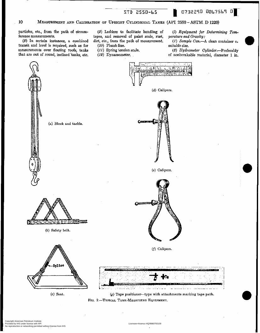
particles, etc., from the path of circum- ference measurements.
(8) I n certain instances, a combined transit and level is required, such as for measurements over floating roofs, tanks that are out of round, inclinedkmks, etc.
(9) Ladders to facilitate handling of tapes, and removal of paint scale, rust, dirt, etc., from the path of measurement.
(1 ) Equipment for Determining Tem- perature und Gravity:
(i) Sample Can.-A clean container oI suitable size.
(2) Hydrometer CyZinder.-Preferably of nonbreakable material, diameter 1 in.
(10) Plumbline. (il) Spring tension scale. (12) Dynamometer. .
(a) Block and tackle.
( b ) Safety belt.
(d) Calipers.
(e) Calipers.
cf) Calipers.
(c) Seat. (8) Tape positioner-type with attachments marking tape path.
FIG. 2.-TYPIcAL TANK-MEASURINO EQUIPMENT.
Copyright American Petroleum Institute Provided by IHS under license with API Licensee=Aramco HQ/9980755100
Not for Resale, 11/25/2006 02:32:33 MSTNo reproduction or networking permitted without license from IHS
--`,,,`,,,```,,```,``,`,,,`,`,`-`-`,,`,,`,`,,`---

S T D 2550-65 I- 0732290 0067570 7
MEASUREMENT AND CALIBRATION OF UPRIGHT CYLINDRICAL TANKS (API 2550 - ASTM D 1220) 11
greater than the outside diameter of the hydrometer to be used, height 1 in. greater .han the portion of the hydrometer which is immersed beneath the surface of the liquid.
(3) Hydrometer.-Plain form or com- bined thermometer and hydrometer known as a thermohydrometer, calibrated in terms of API gravity, the range to be a suitable portion of the interval between O and 100" API and graduated in 0.1" API and conforming to Specifications E 100, for ASTM Hydrometers.'
(4) Thermometer.-ASTM Gravity Thermometer, total immersion, having a range of -5 to 215 F and conforming to the requirements for Thermometer 12 F as prescribed in Specifications E 1, for ASTM Thermometers.' NOTE 4.-For making gravity measure-
ments, reference should be made to APZ Standard 2544-ASTM 0 2 8 7 : Method of Test for APZ Gravity of Crude Petroleum and Petroleum Products.
(m) Liquid Calibration.-Liquid cali- bration of the entire or partial volume of tanks is sometimes recommended in lieu of physical measurement of dimensions and calculations of tank volumes. Liquid calibration is especially useful for the following conditions: The critical zone of a floating roof; irregularly shaped por- tions of tanks, particularly bottoms; un- stable bottoms where the deflection of the bottom varies with the liquid-head height in the tank or water-table level of its foundation; tanks that are unevenly tilted, irregular in shape, or inaccessible for measurement. Instructions for liquid calibration for these or any other reasons may be found in API Standard 2555- ASTM D 1406. General Practices
be observed a t all times. 7. (a) Prevailing safety practices should
(b) The number of men required in a
FIG. 3.-COMBINATION PITCH INDICATOR AND LEVEL. strapping crew will depend upon condi- tions to be encountered, such as the ex- perience of the men, the weather, strap- ping schedule, rigging available, and the height of tanks. As a general rule, a crew of three may be considered practical, in- cluding at least one man who has had previous tank-measuring experience. It would also be decidedly advantageous if the previous experience included some amount of office work in the calculation of gage tables.
(c) Do not use ropes, ladders, or other rigging of questionable strength or condi- tion. This is particularly important in re- gard to rope that has been stored while wet, saturated with oil or gasoline, or used on an acid tank.
PART I. MEASUREMENT PROCEDURES
FIG. 4.-CUP-CASE THERMOMETER
( d ) If ladders are used, all rungs should be inspected and tested a t ground level. Ladders should not be "stretched," for convenience, beyond their normal safe working range. It should be understood that the inherent danger in ladders may be increased considerably by conditions on a tank job, such as possibly soggy footing, relatively smooth upper bearing surface, strong gusts of wind, sudden slack or pull in circumference tape, etc.
(e) All measurements and descriptive data taken a t the tank site should be checked and legibly recorded immediately, with the recording assigned, preferably, to one man.
(f) Take time to do a good job.
Conditions for Measurements 8. (a) All data, and procedures whereby
they are obtained, necessary for the prepa- ration of gage tables should be supported by sound engineering principles.
(b) Measurements should be taken only after the tank has been filled at least once a t its present location with liquid at least as dense as it is expected to contain.
' 1966 Book of ASTM Standards, Part 18.
The usual water test, if made, will meet this requirement.
(c) The calibration procedures which are outlined herein are based upon in- ternal cleanliness of the tank. The interior upright cylindrical surface and roof-sup- porting members, such as columns and braces in the tank, should be clean and free from any foreign substance including, but not limited to, residue of commodities adhering to the sides, rust, dirt, emulsion,
and paraffin. Examination and inspection of a tank may indicate the need for thor- ough cleaning if accuracy in the calibration is to be achieved. Internal incrustation or adhesion has the same effect on the tank capacity as deadwood and should be ac- counted for in the same manner. For ad- ditional information for various solutions to this problem, see APZ Bulletin on Zn- crustation (Supplement No. 1 to API Standard 2500).
Copyright American Petroleum Institute Provided by IHS under license with API Licensee=Aramco HQ/9980755100
Not for Resale, 11/25/2006 02:32:33 MSTNo reproduction or networking permitted without license from IHS
--`,,,`,,,```,,```,``,`,,,`,`,`-`-`,,`,,`,`,,`---
S T D 2550-65 1 0732290 006757L 7 c -
12 MEASUREMENT AND CALIBRATION OF UPRIGHT CYLINDRICAL TANKS (API 2550 - ASTM D 1220)
(d ) Tanks m’th a Nominal Capacity of 500 Bbl OT Less.-These tanks may be strapped at any condition of fill, provided they have been filled a t least once at their present location. Small movements of oil into or out of such tanks are allowed dur- ing strapping.
(e) Tanks with a Nominal Capacity of More Than 500 Bbl:
(1) Bolted Tanks must have been filled a t least once at their present location and must be at least two-thirds full when strapped, Small movements of oil into or out of such tanks are allowed during strap- ping.
(2) Riveted T a n h and/or Welded Tanks must have been fiiled at least once a t their present location. They may be strapped at any condition of fili and the full capacity computed as shown in Sec- tion 53. No movement of oil into or out of such tanks is allowed during the strapping operation.
Disputes
9. I n case of controversy, when agree- ment cannot be reached between the buyer and the seller, a joint strapping should be taken. This joint strapping should be con- sidered finai.
Tank Numbers 10. (a) Identification.-Each t.ank
should be identified clearly and legibly by number or by some other suitable marking, but this identification should not be painted on hoops or tank attachments.
(b) Restrapped Tanks.-A tank which has been restrapped should be identified completely, either by renumbering or by some other adequate method.
Interrupted Measurements 11. Interrupted tank measurement work
may be continued at a later date, without repeating the work previously completed, provided ali records of the work are com- plete and legible. Movement of liquid into or out of the tank may be tolerated, pro- vided a clearly marked liquid gage and average temperatures of both liquid and outside atmosphere are included as parts of the subsequent strapping operations.
Descriptive Data 12. (a) Complete descriptive data
should be entered on the Tank Measure- ments Record Form being used. Suggested record forms are shown in Figs. 6 to 9 and Tables III and IV (see Section 21).
(b) Usually the commonly used name
for a tank’s contents may be a sufficient description. I n those casa in which a more accurate description is desired, as for ex- ample in critical measurements, the API gravity and the temperature of the tank’s contents should be obtained and recorded.
(c) Supplemental pencil sketches or notations, each completely identiñed, dated, and signed, should accompany the strapping. These should be made to indi- cate typical horizontal and vertical joints; number of plates per ring; location of rings at which thickness of plates change; arrangement and size of angles at top and bottom of shell; location and size of pipes and manways; dents and bulges in shell plates; direction of lean from vertical; procedure used in bypassing a large ob- struction, such as a cleanout box or insula- tion box located in the path of a circum- ferential measurement; location of tape path different from that shown in Figs, 11 to 19; location and elevation of a possible datum plate; and all other items of inter- est and value which will be encountered.
( d ) Entries of data on a tank measure- ments record form, or supplemental data sheets, should not be erased. If alteration is necessary, the entry to be changed should be marked out with a single pencil line and the new data recorded adjacent to it.
UPRIGHT CYLINDRICAL TANK SHELLS-ABOVEGROUND
Classification of Tank Services
13. (a) The degree of accuracy desired in the completed gage table for a specific tank will be the governing factor in de- termining the procedure to be followed. Tanks may be considered to fall within one of two broad classifications :
(1) Operating Control.-Tanks used in intraplant or intradepartmental service.
( 2 ) Critical Measurements .-Tanks used in intercompany or interdepartmental service.
NOTE 5.--It should be remembered that the maximum obtainable accuracy in gage tables for all tanks, regardless of service, is of value for inventory.
(b) A critical measurements gage table is more precise (Note 6) than an “operat- ing control” gage table (Note 7) because adjustments are included for the effects of the following variables:
(1) Differences in requirements for cir- cumferential measurements (see Figs. 10 to 25).
( 2 ) Expansion and contraction of steel
(3) Expansion and contraction of stet.
(4) Tilt from a vertical position. (6) Tank bottoms that are irregular in
shape, or unstable under varying liquid loads, or both.
NOTE 6.-Tolerances for measurements and calculations included in this procedure apply to the development of both critical measurements and operating control gage tables.
NOTE 7.-Adjustment for effect of such variables may be incorporated in gage tables for operating control tanks. The gage table should indicate the adjustments which have been incorporated. Expansion and Contraction of Steel Tank
Shells Due to Liquid Head and Tem- perature 14. These effects may be determined
in accordance with procedures given in Part II, Sections 53 and 54. In the case of the calculation procedure for expansion and contraction due to liquid head, as mentioned in Section 53(c), Item (í), a tank may be measured empty or at any condition of fill. When no liquid-head cor- rection is to be made, a tank should t measured only when at least two-third:. full. In either case, the strapping record should include liquid gage, API or specific gravity of liquid, and the average temper- ature of the liquid and the temperature of the air adjacent to shell at time of cir- cumferential measurements. Effect of Tilt on Cylindrical Tank Shell
15. The amount of tilt in shell height should be measured and recorded. The measurements for possible tilt may be made in conjunction with measurements of shell heights [see Section 19(a)].
tank shell due to liquid heads.
tank shell with temperature.
Recalibration of Welded, Riveted, or Bolted Tanks 16. (a) In order to obtain a check on
the accuracy of existing circumference measurement records, the tank circum- ferences in question should be remeasured at the same circumference measurement elevations as taken originally. The check measurements should be made in accord- ance with rules for circumferential meas- urements as covered in this standard.
(b) If the final check measurements taken at a later date-and after further service sufficient to induce maximum stres‘ variations in the shell; permanent “set, if any; etc.-do not check the questioned
Copyright American Petroleum Institute Provided by IHS under license with API Licensee=Aramco HQ/9980755100
Not for Resale, 11/25/2006 02:32:33 MSTNo reproduction or networking permitted without license from IHS
--`,,,`,,,```,,```,``,`,,,`,`,`-`-`,,`,,`,`,,`---

STD 2550-65 0732290 0 0 6 7 5 7 2 Ú I -
MEASUREMENT AND CALIBRATION OF UPRIGHT CYLINDRICAL TANKS ( M I 2550 - ASTM D 1220) 13
_- A T ~ . per cent sr Vol- tune -
circumference measurements within the vpropriate allowance shown in Table I, A complete recalibration and new gage tables based thereon should be required.
(c) Vertical or upright tanks should be remeasured and recalibrated:
(1) When restored to service after be- ing disconnected or abandoned.
(2) When disassembled and re-erected, or when “moved bodily.” (3) When deadwood is changed, when
concrete or other material is placed on the bottom or on the shell of the tank, or when the tank is changed in any manner which would affect the incremental or total vol- ume.
oulu Typa
NOTE d.-Experience in checking the cir- cumference measurements of bolted steel tanks indicates that auch tanks, in sizes up to a nominal capacity of loo0 bbl, show no significant volumetric change over a period of 10 yr. Tanks having a nominal capacity in excess of loo0 bbl show volumetric changes of a small order of magnitude over a 10-yr period which may’be sufficient to warrant recalibration of the tank when considering the type of service and the value of the prod- uct involved.
Tolerances 17. (a) Single circumferential measure-
ments should be read and recorded to the nearest 0.005 ft, which is equal to one-half of the distance between two adjacent hundredth-foot division marks on the tape. A segmental circumferential meas- urement, such as is made in conjunction with the use of a step-over, should be estimated and recorded to the nearest 0.001 ft, which is equal to one-tenth of the distance between two adjacent hundreth- foot division marks on the tape. These in- terpolations should be made by eye. Therefore, all circumferential measure- ments should be recorded through the third decimal place.
( b ) Vertical tank measurements should be read and recorded to the nearest i/8 in.
(c) Thermometers should be read to the nearest scale division.
(d) Tank plate thicknesses should be determined to the nearest 1/64 in.
(e) Deadwood should be determined and located by measurement readings to the nearest ’/s in.
Shell Plate Thickness 18. (a) Where type of construction
leaves the plate edges exposed, a minimum of four thickness measurements should be
Uptoloo,
101 to 200, ‘
201 to 300,
incl ........ incl. . . . . . . . incl.. . . . . . .
TABLE I.-TOLERANCES FOR RECALIBRATION OF WELDED, RIVETED, OR BOLTED STEEL TANKS.
j Welded I Riveted I Bolted I
---- I 0.0100.0400.0200.08c
0.015 O .O20 0.025’0.033
0.020 0.016 0.030’0.021 I
I I I --
1.120 Consider on individual mer- its, by types of C O n E t N C -
Toler in- h
D.03(
0.044
..
..
..
made on each ring at points approximately equally spaced about the circumference. The arithmetical average of the measure- ments for each ring should be recorded; all thickness measurements, properly identified, should be noted on a supple- mental data sheet which should form a part of the measurements record. Care should be taken to avoid plate thickness measurements a t locations where edges have been distorted by caulking.
( b ) Where plate edges are concealed by the type of construction, the strapping record should be marked “not obtainable a t tank.” Alternatively, plate thickness measurements may be obtained as de- scribed in Paragraph (c) .
(c) Plate thickness measurements ob- tained before or during construction, and recorded on a properly identified strapping record, may be accepted. In the absence of any direct measurements of plate thick- nesses obtained and recorded before or during construction, those shown on the fabricator’s drawings may be accepted and so identified in the calculation records. Paint thickness on the various rings should be noted and included with the strapping records.
Vertical Tank Measurements
19. (a) Shell height is the vertical dis- tance between bottom of bottom angle (or top of floor plate) and top of top angle, and should be measured a t a point near the gage hatch. Additional height measurements should be made, as required, a t other identified points sufficient to in- vest.igate and describe known or suspected conditions in the tank, such as tilt or false bottom. Locations of measurements should
.. j
be marked on a supplemental sketch in plan view.
( b ) Gaging height is the vertical dis- tance between the reference point on the gage hatch and the striking point on tank floor or on gage datum plate, and should be measured at the commonly used point on the hatch rim. If a gaging reference point other than the top of the gage hatch rim is known to be commonly used, a description of the reference point should be included in the record.
(c) A comparison should be made im- mediately of the gaging height with the sum of shell height plus the height (ap- proximate) from the top of the top angle to the level of the gaging point on the hatch rim, in order to investigate the possible existence of a gaging datum plate or false bottom. The result of this field in- vestigation should be recorded by identi- fying the gaging height as a distance to the floor (Note 9) or to the datum plate. The measurements and calculations in- volved should be attached to, and become a part of, the measurements record.
NOTE 9.-If a false bottom is known or suspected to be present, the record should be so marked.
( d ) Effective inside tank height is a vertical distance along the gaging path. This is of primary concern to the gage table calculator in that it establishes the upper and lower limits of variable gages to be provided for in the gage table. If the effective tank height can be obtained directly on the tank, it should be meas- ured and reported as such. If it cannot be measured directly, the strapper should assure himself that other vertical meas-
Copyright American Petroleum Institute Provided by IHS under license with API Licensee=Aramco HQ/9980755100
Not for Resale, 11/25/2006 02:32:33 MSTNo reproduction or networking permitted without license from IHS
--`,,,`,,,```,,```,``,`,,,`,`,`-`-`,,`,,`,`,,`---

0732240 00b7573 ~
14 MEASUREMENT AND CALIBRATION OF UPRIGHT CYLINDRICAL TANKS (API 2250 - ASTM D 1220)
O per cent (exposed portion) on each of lower 4 rings and 12 in. below top of top r'ing."
Lowest exposed portion above horizontal rivet rows on each of lower 4 rings and 12 in. below top of top ring.a
Lowest exposed portion above horizontal rivet rows on each ring to and including first two shingled, and 12 in. below top of top ring."
uremeiits taken and recorded will permit. the calculator to develop therefrom the effective inside tank height.
(e) I n some installations, an overflow line or other appurtenance is connected to the tank shell just below the top angle and provides a potential liquid overflow level at some point below the top of the shell. The measurement record should in- clude a complete description of such a connection, including size and location, and whether or not a valve, which can be closed and sealed, is included in the line. If such a valve is present, its location should be included in the record. If the connection cannot be closed and sealed against overflow, then the effective inside tank height is the vertical distance from the striking point on the tank floor, or gaging datum plate, upward to the level a t which the tank's contents will begin to overflow; the tank capacity between the point of overflow and the tank roof should be disregarded in the gage table. If the connection can be closed and sealed against overflow, then the effective inside tank height, and the gage table, should extend upward to the top of the top angle. In this latter case, in which the gage ta- ble is extended upward beyond the con- nect.ion, the gage table should include a note, at the elevation of the connection, citing its presence and stipulating the condition under which that portion of the gage table may be used.
(f) Liquid in tank at time of strapping should be gaged and its mean temperature and API gravity determined. Checked results should be recorded, including a de- scription of gaging procedure used; i.e., whether innage or outage.
( 9 ) Shell plate height of each ring should be measured and recorded.
O per cent (exposed portion) on each ring and 12 in. below top of top ring."
Lowest exposed portion above horizontal rivet rows oneach ring, and 12 in. below top of top ring."
Lowest exposed portion above horizontal rivet rows on each ring, and 12 in. below top of top ring..
NOTE lO.-Where rings are lapped hori- zontally, the lap should be reported so that the inside height of the ring can be devel- oped by the calculator.
Preparations for Circumferential Meas- urements 20. (a) The strapper should first de-
termine where circumferential measure- ments are to be taken. A summary of ele- vations for circumference measurements on various types of upright cylindrical tanks is shown in Table II. Circumfer- ential tape paths located at elevations shown in the appropriate illustration in Figs. 10 to 25 should be examined for ob- structions and type of upright joints. Pro- jections of dirt and scale should be re- moved along each path. Occasionally, some
feature of construction, such as a manway or insulation box, may make i t impractica- ble to use a circumference elevation pre- scribed on the appropriate illustration. If the obstruction can be spanned by a step- over, then the circumference should be measured a t the prescribed elevation, us- ing a suitable procedure in Section 21. If the obstruction cannot be conveniently spanned by a step-over, then a substitute path, located nearer to the center of the ring, may be chosen. The strapping record should include the location of the substi- tute path and the reason for the departure.
( b ) The type and characteristics of upright joints should be determined by close examination in order to establish the procedure of measurement and equip- ment required. In the case of butt-welded joints, or butt-strap or lap joints at which voids between tape and shell at the joints will be caused only by butt-strap or plate thickness, uniform at each joint, then
circumferences may be measured in ac- cordance with the procedure described i~ Section 21(a) and ( b ) , without the USL
of a step-over. In the case of butt-strap or lap joints in which voids at joints are not uniform because of interference by rivet heads or other features, then cir- cumferences should be measured in ac- cordance with the procedure described in Section 21 (a ) and (c), which incorporates the use of a step-over at each joint. I n the case of flanged upright joints, cir- cumference measurements should be made in accordance with the procedure de- scribed in Section 21(a) and (f) , which incorporates the use of a step-over or special clamps.
(c) The amount of tension, in pounds, to be applied to the measuring tape in ail cases should have been determined previ- ously in accordance with the procedure de- scribed in Section 5(a) or ( b ) .
TABLE II.-ELEVATIONS FOR CIRCUMFERENCE MEASUREMENTS ON VARIOUS TYPES OF UPRIGHT CYLINDRICAL TANKS. _ _ _ _ ~ ~
Type of Tank Construction
Welded Steel, One or Mor1 Rings
Riveted Steel, Shingled Arrangement
Riveted Steel, In-and-Out Arrangement
Riveted Steel, Combina- tion Shingled and In- and-Out Arrangement
Steel Tank One Ring High
Bolted Steel, Lapped Ver-
Bolted Steel, Flanged Ver
Corrugated Steel Wooden Stave, Plain
Wooden Stave, Barrel
Riveted Lap Joints
tical Joints
tical Joints
Tapered
Shape
Circumference Measurement Elevitions
Operating Control I Critical Measurements
20 per cent down from top of exposed heightof each of 3 lower rings, below circum. ferential weld on outer sur. face, and 20 per cent dowr from top of top ring, whether butt or lap joints.
20 per cent of exposed portio1 of each ring, whether but, or lap j0ints.b
25 and 76 per cent above bottom of each ring.
75 per cent above bottom of each ring.
50 per cent of each ring, in valley. O f t 6 in. above inside bottom surface and at 2 f t O in.
intervals thereafter. O f t 6 in. above inside bottom surface and a t 1 ft O in.
intervals thereafter.
a When bottom angle is weldedrtake lowermost circumference 12 in. above bottom of bottom ring. Where tank shells are of composite construction, take measurements in ac- cordance with instructions above for each type of construction.
b For one-ring tanks, two circumferential measurements shall be taken at 20 per cen and 80 per cent down from the top of the rin . For tanks of more than one ring, if obstruc. tions block the tape path at the 20 per cent town plane, the measurement may be taken a t a point 80 per cent down. If circumference measurements taken on successive rings indicate unusual variations or distortions, sufñcient additional measurements should be taken to satisfy the requirements of all concerned.
Copyright American Petroleum Institute Provided by IHS under license with API Licensee=Aramco HQ/9980755100
Not for Resale, 11/25/2006 02:32:33 MSTNo reproduction or networking permitted without license from IHS
--`,,,`,,,```,,```,``,`,,,`,`,`-`-`,,`,,`,`,,`---

c S T D 2550-65 0732290 0067574 4
15 MEASUREMENT AND CALIBRATION OF UPRIGHT CYLINDRICAL TANKS (API 2550 - ASTM D 1220)
Circumferential Measurements
21. (a) For the measurements described in Paragraphs ( b ) , (c), (d), or (e), a cir- cumference tape of sufficient length to en- circle the tank completely should be used, in which case measurement of total cir- cumference with one reading should be taken. In the event that the tank circum- ference is too great to be completely en- circled by the tape, increments of circum- ference measurement should be read and recorded to the nearest 0.005 ft. For the measurements described in Paragraph (f) , where the length of circumferential path to be measured at any one time is limited to the distance between extremities of the spanning instrument in adjacent locations, any approved tape, with either of the two types of graduations described in Section 5 ( b ) , may be used. In ail cases, the tape to be used should be applied to the tank surface, at the prescribed elevations, by the continuous wraparound procedure, as described in Section 5 ( b ) . All points at which circumferential readings (Note 11) are taken should be located at least 2 ft from an upright joint. After a circum- ferential measurement reading has been taken, the tension should be reduced suf- ficiently to permit the tape to be shifted. It should then be returned to position and required tension and another reading taken. This procedure should be repeated until two equal readings have been ob- tained. The equal readings should be re- corded as the circumferential measure- ment at that location.
NOTE 11.-The word “reading” is used in this paragraph for convenience and is not intended to indicate B difference in meaning from the word “estimate” used in the proce- dures described in Paragraphs ( d ) and ( e ) .
(b ) Butt-welded joints a.t which there is no void between tape and tank sheil, or butt-strap or lap joints at which void be- tween tape and tank shell is uniform at all joints: When the circumference measur- ing tape is in contact with the tank sur- face a t ail points along its path, circum- ference measurements should be made and checked .in accordance with Paragraph (a). The checked measurements should be recorded as final measurements. When butt-strap or lap joints cause uniform voids between tape and tank sheil a t each joint, circumference measurements should be made in accordance with Paragraph (a) . Measure and record the width and thickness of butt straps, and record the number of butt straps in each ring. In
/% RADIUS OF TANK
POINT AT WHICH SHELL DEPARTS FROM SCRIBED CIRCLE
OUTSIDE CIRCLE OF TANK OR PATH OF TAPE WHEN CORRECTED CAPACITY TO BE DEDUCTED
LINE OF SCRIBED CIRCLE ACTUAL TAPE RISE ONE HALF PLATE THICKNESS
FROM TANK
POINT AT WHICH SHELL DEPARTS FROM SCRIBED CIRCLE
PLATE THICKNESS
FIG. F>.-TRUE C I R C U N F E R E N C E versus TAPE P A T H A T AXIAL LAP JOINT AWAY FROM CIRCUMFERENTIAL JOINT.
the case of lapped joints, measure and record the thickness of exposed lapped plate, Fig. 5, at at least three joints in each ring about the circumference, and record the number of such joints in each ring. The measured circumferences, properly checked and recorded, should be corrected later for tape rise as described in Part II, Sec- tion 5 2 ( c ) or ( d ) .
(c) When butt-strap or lap joints, or tank shell, include rivets or other features which exert uneven effects on the re- sultant void between the tape and tank, from joint to joint, then a step-over wil l be required. The span of the instrument should be measured prior to use in ac- cordance with Section 6(i), Item (6). The
step-over must be of sturdy construction, either adjustable or fixed in spread, but an adjustable step-over is preferable. The two legs must be separated by a distance sufficient to span each void encountered between tape and shell. The legs must be of sufficient length to prevent contact be- tween the interconnecting member and the tank plate or obstruction. The manner in which the step-over may be used is re- lated to the type of measuring tape used; i.e., whether the tape is graduated in hundredths of a foot throughout its length [see Paragraph (d ) ] or in feet only, with an extra 1-ft length at the zero end gradu- ated in tenths and hundredths of a foot [see Paragraph (e)].
Copyright American Petroleum Institute Provided by IHS under license with API Licensee=Aramco HQ/9980755100
Not for Resale, 11/25/2006 02:32:33 MSTNo reproduction or networking permitted without license from IHS
--`,,,`,,,```,,```,``,`,,,`,`,`-`-`,,`,,`,`,,`---
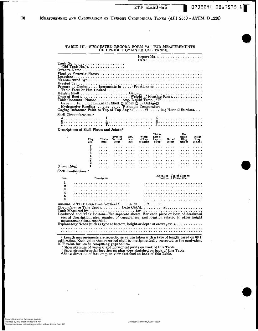
TABLE 111.-SUGGESTED RECORD FORM “A” FOR MEASUREMENTS OF UPRIGHT CYLINDRICAL TANKS.
Report No.:. .......................... Date:. ................................
Tank No.:. ............................. (Old Tank No.) :. .....................
Owner’s Name :. ....................................................................... Plant or Property Name:. ............................................................. Location: ............................................................................. Manufactured by:. .................................................................... Erected by:. .......................................................................... Prepare. .. .Copies . . . . . .Increments in. ..... : Fractions to , ............................
Table Form or dize Desired:. ........................................................ Height: Shell. ............................. Gagin ..................................... Type of Roof:. ............................ .Weigh of Floating Roof :. . . . . . . . . . . . . . . . . . Tank Contents-Name:. .............. .Avg. Liquid Temp., O F : , .......................
Gaging Reference Point to Top of Top Angle: ...... f t . :. ... in.; Normal Service:. . . . Shell Circumferences :a
Gage:. . . . f t . . . .in.; Innage to: Shelf 0 Floor 0 or Outage0 Hydrometer Reading: . . . . at ...... OF Sample Temperature
A ....................... D .......................... G .......................... B ....................... E .......................... EI .......................... C . ...................... F.. ........................ J. ..........................
Descriptions of Shell Plates and Jointe:b
Type of Set, Ring Thick- Vertical inor No. ness Joint out
7 . . . . . . . . . . . . . . . . . . 6 . . . . . . . . . . . . . . . . . . 5 . . . . . . . . . . . . . . . . . . 4 . . . . . . . . . . . . . . . . . . 3 . . . . . . . . . . . . . . . . . . 2 . . . . . . . . . . . . . . . . . .
(Btm. Ring) 1 . . . . . . . . . . . . . . . . . . Shell Connections:“
No. Description
1 .................................. 2 .................................. 3 ..................................
Width of Lap
or Strap
. . . . . . . . . . . . . . . . . .
. . . . . . . . . . . . . . . . . .
. . . . . .
. . . . . . . .
. . . .
Thick- ness of Lap or Strap
...... . . . . . . . . . . . . . . . . . .
. . . . . . . . . . . . . . . . . .
EX- No. Joints of Hei& %Td . . . . . . . . . . . . . . . . . . . . . . . . . . . . . . . . . . . . . . . . . . . . . . . . . . . . . . . . . . . . . . . . . . . . . . . . . . . . . . . . . . . .
Elevation-Top of Floor to Bottom of Connection
........................ ........................
........................
Inside
G%t
. . . . . . . . . . . . . . . . . . . . . . . . ...... ...... ......
...... ...... ...... 4 ................................... ................................... 5 ................................... ................................... 6 ................................... ...................................
Amount of Tank Lean from Vertical:d . . . . in. in . . . . f t .... in. Circumference Tape Used:. . . . . . . . . . . . Date Chk’d.. . . . . . . . . . . . at .................... Tank Measured by:. .......................... .for .................................... Deadwood and Tank Bottom-Use separate sheets. For each piece or item of deadwood
record description, size, number of occurrences, and location related to other height measurement data recorded.
Explanatory Notes (such aa type of bottom, height or depth of crown, etc.). . . . . . . . . . . . . . . . ..................................................................................... ..................................................................................... a Length measurements are recorded aa values taken with a’tape of length based on 68 F
calibration. Each value thus recorded shall be mathematically corrected to the equivalent 60 F value for use in computing gage-tables.
b Show sketches of vertical and horizontal joints on back of this Table. Show circumferential location on plan view sketched on back of this Table. Show direction of lean on plan view sketched on back of this Table.
Copyright American Petroleum Institute Provided by IHS under license with API Licensee=Aramco HQ/9980755100
Not for Resale, 11/25/2006 02:32:33 MSTNo reproduction or networking permitted without license from IHS
--`,,,`,,,```,,```,``,`,,,`,`,`-`-`,,`,,`,`,,`---

S T D 2550-65
MEASUREMENT AND CALIBRATION OF UPRIGHT CYLINDRICAL TANKS
I O7 (API 2550-
32290 0067
‘ASTM D 1220)
‘576
17
TABLE IV.-SUGGESTED RECORD FORM “B” FOR MEASUREMENTS OF UPRIGHT CYLINDRICAL TANKS.
Report No.:. .................. Date:. ........................
Tank No.: .......................... (Old Tank No.) : . . . . . . . . . . . . . . . . . .
Owner’s Name:. ....................................................................... Plant or Property Name: ............................................................... Location: ............................................................................. Manufactured by:. .................................................................... Erected by:. .......................................................................... Prepare .... Copies, ...... Increments in ..... .: Fractions to .........................
Table Form or Size Desired:. ........................................................ Height: Shell . . . . . . . . . . ; .. . . . . . . . . . . . . . . . . . Gaging ................................... Type of Roof: .......................... Weight of Floating ?of:, .................... Tank Contents-Name: ................ Avg. Liquid Temp., F:. ......................
Gage: . . . . f t .... in.; Tank Service: ............ API Gravity:. ..................... Hydrometer Reading: ........ at ........ O F Sample Temperature
Shell A. B.
-C .
Circumferences :” ....................... D .................... ....................... E .................... ....................... F ....................
Descriptions of Shell Plates and Joints:
Type of v0g Thick- Vertical Set, in ness Joint or out
7 ...................... 6 ...................... 5 ...................... 4 ...................... 3 ...................... 2 .......................
(Btm. Ring) 1 ......................
....... G ........................ ....... H ........................
....... J ........................
Width of Lap or Strap
........
.........
........
........
. . , . . , . .
. . . . . . . . Deadwood and Remarks (use reverse side if necessary) :
Description NO. Size
.......................................................
.......................................................
. . . . . . . . . . . . . . . . . . . . . . . . . . . . . . . . . . . . . . . . . . . . . . . . . . . . . . .
. . . . . . . . . . . . . . . . . . . . . . . . . . . . . . . . . . . . . . . . . . . . . . . . . . . . . . .
. . . . . . . . . . . . . . . . . . . . . . . . . . . . . . . . . . . . . . . . . . . . . . . . . . . . . . .
. . . . . . . . . . . . . . . . . . . . . . . . . . . . . . . . . . . . . . . . . . . . . . . . . . . . . . . Type of Bottom:. ...................... .Height of Crown:. . Witneks:. ........................... Measurements by:. ....
. , . . , . . .
Thick- ness of inside Lap or No. of Rj,n Strap Joints He&
....................
.................... .................... ....................
....................
....................
....................
Elevation
From To ....................... ....................... ....................... ....................... ....................... ....................... ......................... .........................
0 Length measurements are recorded aa values taken with a tape of length based on 68 F calibration. Each value thus recorded shall be mathematically corrected to the equivalent 60 F value for use in computing gage tables.
Copyright American Petroleum Institute Provided by IHS under license with API Licensee=Aramco HQ/9980755100
Not for Resale, 11/25/2006 02:32:33 MSTNo reproduction or networking permitted without license from IHS
--`,,,`,,,```,,```,``,`,,,`,`,`-`-`,,`,,`,`,,`---

r STD 2550-65 0732290 0067577 O
MEASUREMENT AND CALIBRATION OF UPRIGHT CYLINDRICAL TANKS (API 2550 - ASTM D 1220)
LOCATIOII HEASURED By DATE EFFECTIVE DATE TAIIK HUMER
BUTT WELDED
E
FIG. B.-EXAMPLE OF RECORD FORM FOR MEASUREMENT OF UPRIGHT TANK SHELL, BUTT- AND LAP-WELDED.
Copyright American Petroleum Institute Provided by IHS under license with API Licensee=Aramco HQ/9980755100
Not for Resale, 11/25/2006 02:32:33 MSTNo reproduction or networking permitted without license from IHS
--`,,,`,,,```,,```,``,`,,,`,`,`-`-`,,`,,`,`,,`---

___I 0732240
(MI 2550-ASTM D
DEADWOOD TANK NO.
FROM I TO 1 PIECES I DESCRIPTION
FIG. ".-EXAMPLE OF RECORD FORM FOR DEADWOOD.
O067
1220)
578
19
Copyright American Petroleum Institute Provided by IHS under license with API Licensee=Aramco HQ/9980755100
Not for Resale, 11/25/2006 02:32:33 MSTNo reproduction or networking permitted without license from IHS
--`,,,`,,,```,,```,``,`,,,`,`,`-`-`,,`,,`,`,,`---
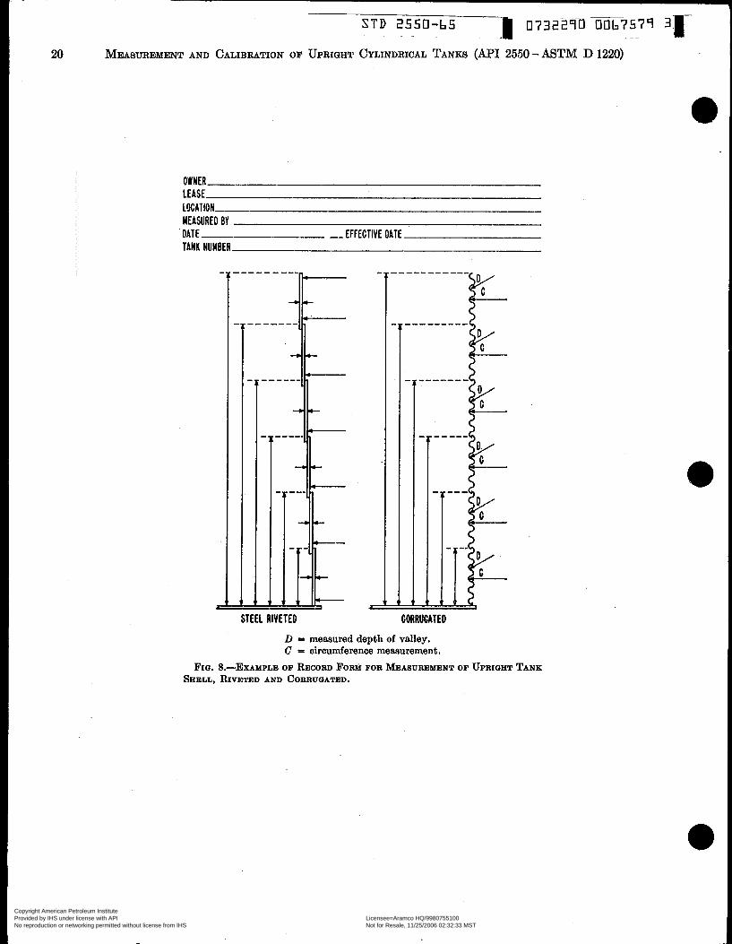
MEASURED BY DATE I EFFECTIVE DATE TANK NUMBER
L I STEEL RIVETED
<
CORRUGATED
D = measured depth of valley. C = circumference measurement.
FIG. &--EXAMPLE OF RECORD FORM FOR MEASUREMENT OF UPRIGHT TANK SHELL, RIVETED AND CORRUGATED.
Copyright American Petroleum Institute Provided by IHS under license with API Licensee=Aramco HQ/9980755100
Not for Resale, 11/25/2006 02:32:33 MSTNo reproduction or networking permitted without license from IHS
--`,,,`,,,```,,```,``,`,,,`,`,`-`-`,,`,,`,`,,`---

-1 0732290
(API 2550 - ASTM
0067580
D 1220) 21
MEASURED BY DATE EFFECTIVE DATE TAHK HUMBER
BOLTED T A W 1,2, AUD 3 RIHG
FIQ. EXAMP AMPLE OF RECORD FORM FOR MEASUREMENT OF UPRIGHT TANK SHELL, BOLTED.
Copyright American Petroleum Institute Provided by IHS under license with API Licensee=Aramco HQ/9980755100
Not for Resale, 11/25/2006 02:32:33 MSTNo reproduction or networking permitted without license from IHS
--`,,,`,,,```,,```,``,`,,,`,`,`-`-`,,`,,`,`,,`---
'1 STD 2550-b5 0732270 0067583 I
22 MEASUREMENT AND CALIBRATION OF UPRIGHT CYLINDRICAL TANKS (API 2550-ASTM D 1220)
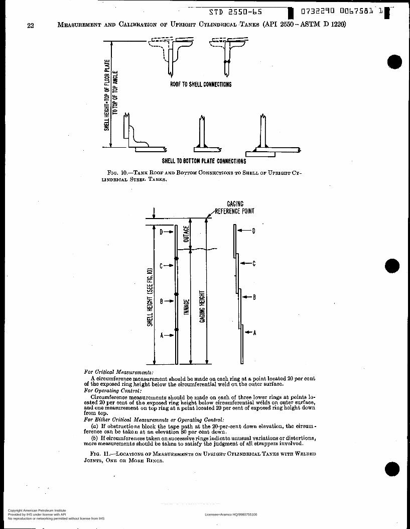
t ROOF TO SHELL CONNECTIONS
U S H E U TO BOTTOM PLATE CONNECTIONS
FIG. TANK ROOF AND BOTTOM CONNECTIONS TO SHELL OF UPRIGHTCY- LINDRICAL STEEL TANKS.
GAGING (REFERENCE POINT
For Critical Measurements: A circumference measurement should be made on each ring at a point located 20 per cent
of the exposed ring height below the circumferential weld on the outer surface. For Operating Control:
Circumference measurements should be made on each of three lower rings at points lo- cated 20 per cent of the .exposed ring height below circumferential welds on outer surface, and one measurement on top ring at a point located 20 per cent of exposed ring height down from top. For Either Critical Measurements or Operating Control:
(a) If obstructions block the tape path at the 20-per-cent down elevation, the circum- ference can be taken at an elevation 80 per cent down.
(b) If circumferences taken on successive rings indicate unusual variations or distortions, more measurements should be taken to satisfy the judgment of all strappers involved.
FIG. LOCATIONS OF MEASUREMENTS ON UPRIGHT CYLINDRICAL TANKS WITH WELDED JOINTS, ONE OR MORE RINGS.
Copyright American Petroleum Institute Provided by IHS under license with API Licensee=Aramco HQ/9980755100
Not for Resale, 11/25/2006 02:32:33 MSTNo reproduction or networking permitted without license from IHS
--`,,,`,,,```,,```,``,`,,,`,`,`-`-`,,`,,`,`,,`---
MEASUREMENT AND CALIBRATION
4 -I
-f --i
w W s O
W W 4 a 3
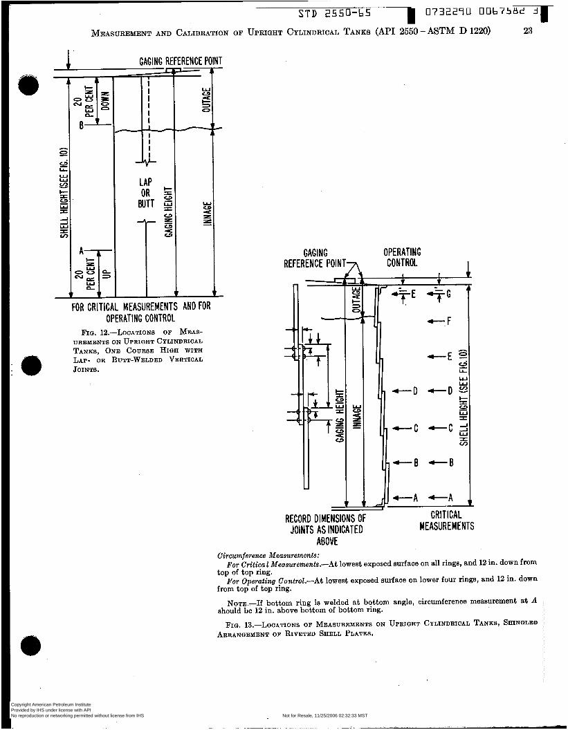
w FOR CRITICAL MEASUREMENTS AND FOR
OPERATING CONTROL F I G . 12.-LOCATIONS OF MEAS-
UREMENTS ON UPRIGHT CYLINDRICAL TANKS. O N E COURSE HIGH WITH LAP- OR BUTT-WELDED VERTICAL io JOINTS.
STD 2550-bS
OF UPRIGHT CYLINDRICAL TANKS (API 2550
0732290 0067LiBc! 3 -r 23 -ASTM D 1220)
GAGING REFERENCE P O I N T 7
W W U 8- æ O /
OPERATING CONTROL I
L
FKl I ILAL MEASUREMENTS
RECORD DIMENSIONS OF JOINTS AS INDICATED
ARIIVF "Y".L
Circumference Measurements: For Critica E Measurements.-At lowest exposed surface on all rings, and 12 in. down from
top of top ring. For Operating Control.-At lowest exposed surface on lower four rings, and 12 in. down
from top of top ring.
should be 12 in. above bottom of bottom ring. NOTE.-If bottom ring is welded at bottom angle, circumference meaeurement at A
FIG. 13.-LOCATIONS OF MEASUREMENTS ON UPRIGHT CYLINDRICAL TANKS, SHINGLED ARRANGEMENT OF RIVETED SEELL PLATES.
Copyright American Petroleum Institute Provided by IHS under license with API Licensee=Aramco HQ/9980755100
Not for Resale, 11/25/2006 02:32:33 MSTNo reproduction or networking permitted without license from IHS
--`,,,`,,,```,,```,``,`,,,`,`,`-`-`,,`,,`,`,,`---

GAGING REFERENCE POINT -
I -
073229U 006758j Li r S T D 2550-65 24 MEASUREMENT AND CALIBRATION OF UPRIGHT CYLINDRICAL TANKS ( A H 2550 - ASTM D 1220)
O
O
4 -4
i
i
f f
l
ABOVE
1
v
-
..
-
OPERATING CONTROL 1
‘*E SG ’ . + F
+--E i)
LL w W
+ I
W I
- e - D + D s c3
- r - c -cg I v)
- + - e - 0
4 - A - A T
Circumference Meusurements:
the uppermost point being 12 in. down from top of top ring.
and 12 in. down from top of top ring.
For Critical Measurmnk-At points indioated above on exposed surface of all rings,
For Operating Control.-At points indicated above on exposed surface of lower four rings,
Nom.-If bottom ring is welded at bottom angle, circumference measurement at A should be 12 in. above bottom of bottom ring.
FIQ. 14.-LOCATIONS OF MEASUREMENTS ON UPRIQHT CYLINDRICAL TANKS, IN-AND-OUT ARRANQEMENT OF RIVETED SHELL PLATES.
Copyright American Petroleum Institute Provided by IHS under license with API Licensee=Aramco HQ/9980755100
Not for Resale, 11/25/2006 02:32:33 MSTNo reproduction or networking permitted without license from IHS
--`,,,`,,,```,,```,``,`,,,`,`,`-`-`,,`,,`,`,,`---

0732290 0067584 .t
25
STD 2550-65 r MEASWEMENT AND CALIBRATION OF UPRIQHT CYLINDRICAL TANKS (API 2550-ASTM D 1220)
GAGING REFERENCE POIN
I- S
W S CI
cl
E U CI
T- OPERATING
CONTROL 1 'r &&E -AG
L -F
- W
2 æ O -
-D
-C 1 -B
CRITICAL MEASUREMENTS
II RECORD DIMENSIONS OF JOINTS AS INDICATED
ABOVE
Circumference Measuremenkr: For Critical Measurements.-Measure circumferences at points indicated above on ex-
posed surface of all rings, the uppermost point being 12 in. down from top of top ring. For Operating Control.-Measure circumferences a t points indicated above on exposed
surface of lower rings, to and including first two adjacent rings (from bottom) of similar arrangement, and 12 in. down from top of top ring.
NOTE.-If bottom ring is welded a t bottom angle, circumference measurement at A should be 12 in. above bottom of bottom ring.
IN-AND-OUT AND SHINGLED ARRANGEMENT OF RIVETED SHELL PLATES. FIQ. 15.-LOCATIONS OF MEASUREMENTS ON UPRIQHT CYLINDRICAL TANKS, COMBINATION
Copyright American Petroleum Institute Provided by IHS under license with API Licensee=Aramco HQ/9980755100
Not for Resale, 11/25/2006 02:32:33 MSTNo reproduction or networking permitted without license from IHS
--`,,,`,,,```,,```,``,`,,,`,`,`-`-`,,`,,`,`,,`---

c STD 2550-65 073229U 0067585 9 ~~
h
0 e LLi
W W v, Y
1; 1: IC 1: I C
7 I I I I I I I I I I I I I I I I I I I
-L
AGING REFERENCE POINT
- W c3 U I- s
v
A
W c3 U æ s
Y
FIQ. 16.-LOCATIONS OF MEASUREMENTS ON UPRIQHT CYLINDRICAL TANKS, O N E COURSE HIQH WITH RIVETED VERTICAL LAP JOINTS.
J.
.IA U U c I- = U S
s
G æ U
C
-v "8 q a-
$, B
GAGING REFERENCE I POINT
Cimumjerenee Measurements:
bottom of plate flange.
from top of plate flange.
HORIZONTAL JOINTS AND LAPPED VERTICAL JOIN'PB.
Circumference measurements at A and C to be located 26 per cent of plate height up from
Circumference measurements at B and D to be located 25 per cent of plate height down
FIQ. 17.-LOCATIONS OF MEASUREMENTS ON UPRIGHT CYLINDRICAL TANKS WITH FLANGB~D
Copyright American Petroleum Institute Provided by IHS under license with API Licensee=Aramco HQ/9980755100
Not for Resale, 11/25/2006 02:32:33 MSTNo reproduction or networking permitted without license from IHS
--`,,,`,,,```,,```,``,`,,,`,`,`-`-`,,`,,`,`,,`---
- r 0732ZïO 0067586 O S T D 2550-65
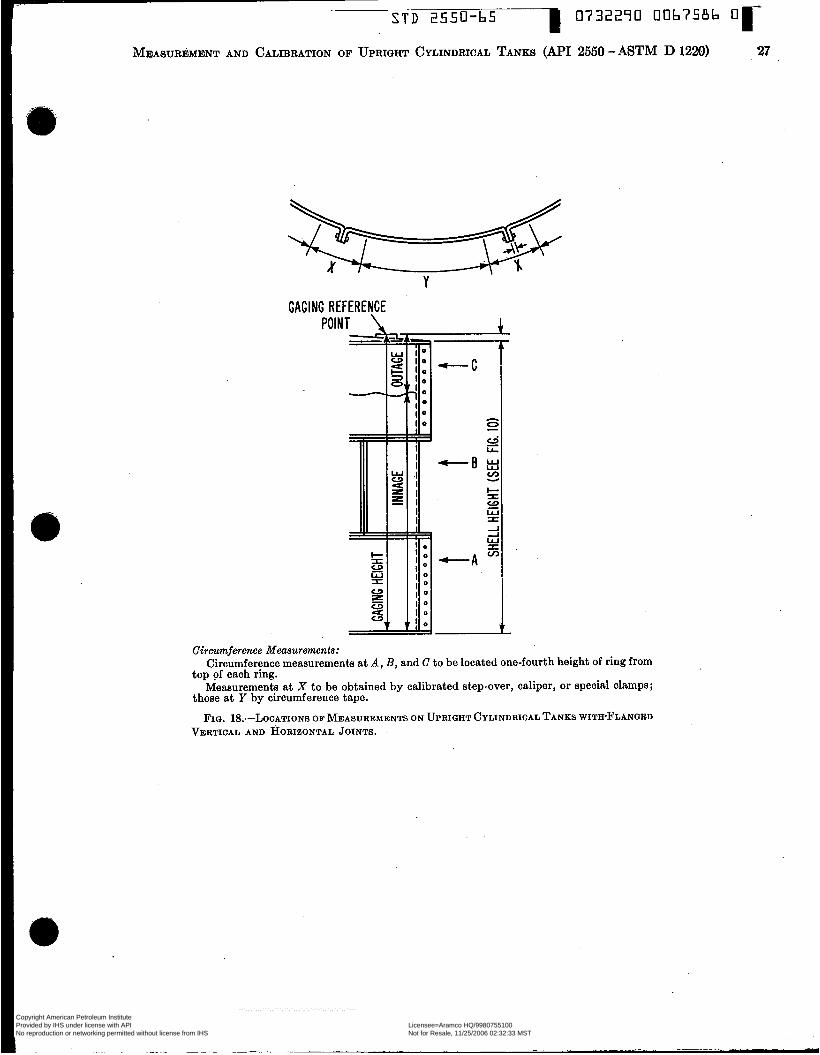
MEASUREMENT AND CALIBRATION OF UPRIGHT CYLINDRICAL TANKS ( N I 2550 - ASTM D 1220) 27
Y GAGING REFERENCE
POI N
Circumference Measurements: Circumference measurements at A , B, and C to be located one-fourth height of ring from
Measurements at X to be obtained by calibrated step-over, caliper, or special clamps;
FIG. LOC LOCATIONS OF MEASUREMENTS ON UPRIGHT CYLINDRICAL TANKS WITH-FLANGED
top of each ring.
those at Y by circumference tape.
VERTICAL AND HORIZONTAL JOINTS. -
Copyright American Petroleum Institute Provided by IHS under license with API Licensee=Aramco HQ/9980755100
Not for Resale, 11/25/2006 02:32:33 MSTNo reproduction or networking permitted without license from IHS
--`,,,`,,,```,,```,``,`,,,`,`,`-`-`,,`,,`,`,,`---

r S T D 2550-65 1 073ais90 00b7CB7 2
28 MEASUREMENT AND CALIBRATION OF UPRIGHT CYLINDRICAL TANKS (MI 2550-ASTM D 1220)
cj LI.. W W v) Y
\\\
/ING REFERENCE POINT
RECORD DIMENSIONS OF CORRUGATIONS
AS INDICATED BELOW
h\\\\\\\\\\\\\\\'c Circumference measurements at A , B, C, and D to be
FIQ. LOCATIONS OF ~MEABUREMENTS ON UPRIGHT
located in valley at center of each ring.
CYLINDRICAL CORRUGATED STEEL TANKS.
CAPACITY LINE Ca acity of tank bottom, A, may be determined by
calcufations baaed on builder's drawings, or by liquid calibration in accordance with API Standard 2655-ASTM D 1406.
FIG. XL-STRAIQHT SHELL TANK WITH INACCESSIBLE PRESSURE-TYPE BOTTOM.
Copyright American Petroleum Institute Provided by IHS under license with API Licensee=Aramco HQ/9980755100
Not for Resale, 11/25/2006 02:32:33 MSTNo reproduction or networking permitted without license from IHS
--`,,,`,,,```,,```,``,`,,,`,`,`-`-`,,`,,`,`,,`---

1
MEASUREMENT AND CALIBRATION OF UPRIGHT CYLINDRICAL TANKS
/- TOP CAPACITY
BUILDERS RADIAL DIWEHSIOHS \
Capacity of bottom, A , and upper curved portion, B , from straight shell to top capacity line, may be determined by calculations based on builder’s drawings or by liquid calibra- tion in accordance with API Standard 2555-ASTM D 1406.
Locations of measurements on welded cylindrical shell are the same aa for welded up- right cylindrical tanks (see Fig. 11).
FIQ. 21.-NODED HEMISPHEROEPAL TANK.
( d ) In a case as described in Para- graph (c), if circumference measurements are made with a step-over and a tape graduated in hundredths of a foot through- out its length, stretch the tape over the joints in accordance with Paragraph (a) , and place the step-over in position a t each location of void between tape and sheil, completely spanning the void, so that the scribing points contact the shell a t an edge of the tape. The length of tape encom- passed by the scribing points, with the tape maintained in proper position and tension, should be estimated to the nearest 0.01 f t (approximately %4 in.). At each step-over location, therefore, the differ- ence between the length of tape encom- passed by the scribing points and the known span of the instrument is the effect of the void, a t that point, on the circum- ference as measured. The sum of such dif- ferences in any given path, subtracted from the measured circumference, will give the corrected circumference.
( e ) In a case as described in Paragraph (c), if circumference measurements are made with a step-over and a -tape gradu- ated in feet only, with an extra 1-ft length a t the zero end graduated in tenths and hundredths of a foot, stretch the tape over the joints as in Paragraph (a), place the step-over in position a t each location
of void between tape and shell, and mark the tank sheil a t the points of contact of scribing points to shell. Each location SO
marked should then be measured with the same tape. For each separate measure- ment, the tape should be reapplied against the tank in proper tension, but so adjusted that a whole-foot marking lies opposite one of the scribed marks, and so chosen that the other scribed mark will lie within the graduated 1-ft extra length a t the zero end, The t.ape length between the scribed marks should be estimated to the nearest û.ûûi f t (approximately 364 in.). The measured circumference should be cor- rected as described in Paragraph ( d ) to obtain the corrected circumference. Al- ternatively, step-over and tape may be used as described in Paragraph ( j ) .
( j ) When obstructions are encountered in the tape path over which it is imprac- ticable to place the tage-for example, the upright flanges on bolted tanks-a span- ning instrument, such as a special clamp (used on bolted tank flanges only) or a step-over (used on bolted tank flanges or dther obstructions), is used to measure a section of the true circumference a t each obstruction. The span of the instrument, in relation to the diameter of the tank be- ing measured, should be determined prior to use. In use, the circumferential sections
I 0732290 0067588 Lt
(API 2550 - ASTM D 1220) 29
along the tape path, and between the suc- cessive outer limita of reach in each ap- plication of the spanning instrument, should be measured with the tape in the usual way, except that the tank shell is not completely encircled. The total cir- cumference, therefore, wiii be the sum of the tape measurements and the spanning instrument measurements. Care must be taken in placing the instrument in a truly level position a t each obstruction to avoid distortions in the circumferential path. In the case of a step-over of relatively long span, the use of a spirit level is rec- ommended as an aid in determining the correct position before scribed marks are struck off on the plates.
Deadwood
22. (a) Deadwood should be accurately accounted for, as to size and location, to the nearest ?A in., in order to permit:
(1) Adequate allowance for the volumes of liquid displaced or admitted by the various parts.
(2) Adequate allocation of the effects a t various elevations within the tank.
( b ) Deadwood should- be measured, if possible, within the tank. Dimensions shown on the builder’s drawings may be accepted if actual measurement is impos- sible.
(c) Measurements of deadwood should show the lowest and highest levels, meas- ured from the t.a& bottom adjacent to the shell, a t which deadwood affects the capacity of the tank. Measurements should be increments which permit allow- ance for its varying effect on tank ca- pacity a t various elevations.
(d) Work sheets on which details of deadwood are sketched, dimensioned, and located should be clearly ideiitiñed and should become a part of the strapping rec- ord.
TANK BOTTOMS
Tank Bottoms-Flat Type
23. (a) Tank bottoms which are flat and stable under varying liquid loads wiii have no effect on tank capacity determined on the basis of geometric principles.
( b ) For critical measurements, where tank bottom conditions of irregular slope or shape and/or instability exist, as de- picted in Figs. 22 through 25, and where correct capacities cannot be determined conveniently from linear measurements, it
Copyright American Petroleum Institute Provided by IHS under license with API Licensee=Aramco HQ/9980755100
Not for Resale, 11/25/2006 02:32:33 MSTNo reproduction or networking permitted without license from IHS
--`,,,`,,,```,,```,``,`,,,`,`,`-`-`,,`,,`,`,,`---
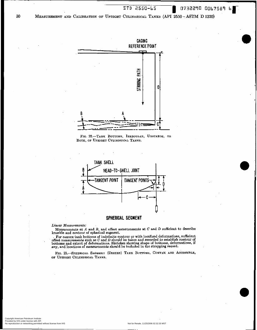
STD 2550-b5 I 0732270 00b7589 q- 30 MEASUREMENT AND CALIBRATION OF UPRIGHT CYLINDRICAL TANKS (API 2550 - ASTM D 1220)
GAGING REFERENCE ‘POINT
B
$.
A
FIQ. 22.-TANK BOTTOMS, IRREQULAR, UNSTABLE, OR BOTH, OF UPRIQHT CYLINDRICAL TANKS.
SPHERICAL SEGMENT Linear Measurements:
Measurements at A and B, and offset measurements a t C and D sufficient to describe knuckle and contour of spherical segment. . For convex tank bottoms of indefinite contour or with localized deformations, sufficient
offset measurements such as C and D should be taken and recorded to establish contour of bottoms and extent .of deformations. Sketches showing sha e of bottoms, deformations, if any, and locations of measurements should be included in t\e strapping record.
OF UPRIQHT CYLINDRICAL TANKS.
.
FIG. Za.--sPHERICAL SEGMENT (DISHED) TANK BOTTOMS, CONVEX AND ACCESSIBLE,
Copyright American Petroleum Institute Provided by IHS under license with API Licensee=Aramco HQ/9980755100
Not for Resale, 11/25/2006 02:32:33 MSTNo reproduction or networking permitted without license from IHS
--`,,,`,,,```,,```,``,`,,,`,`,`-`-`,,`,,`,`,,`---
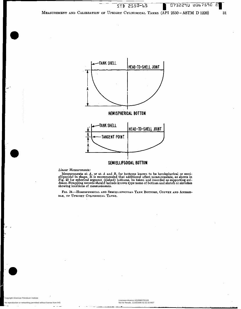
~~
S T D ZCC'J-bS 07322711 uüb ï5 ïû 2
MEASUREMENT AND CALIBRATION OF UPRIGHT CYLINDRICAL TANKS (API 2550 - ASTM D 1220) 31
HEMISPHERICAL BOTTOM
/TANK SHELL 4: HEAD-TO-SHELL JOINT
SEMIELLIPSOIDAL BOTTOM Linear Measurements:
Measurements at A, or at A and B, for bottom known to be hemispherical or semi- ellipsoidal in shape. It is recommended that additional offset measurements, aa shown in Fig. 23 for spherical segment (dished) bottoms, be taken and recorded aa su porting evi- dence. Strapping records should include known type name of bottom and sketcg or sketches showing locations of measurements.
FIQ. ~~.-HEYISPHERICAL AND SEMIELLIPSOIDAL TANK BOTTOMS, CONVEX AND ACCESSI- BLE, OF UPRIQHT CYLINDRICAL TANKS.
Copyright American Petroleum Institute Provided by IHS under license with API Licensee=Aramco HQ/9980755100
Not for Resale, 11/25/2006 02:32:33 MSTNo reproduction or networking permitted without license from IHS
--`,,,`,,,```,,```,``,`,,,`,`,`-`-`,,`,,`,`,,`---

STD 2550-65 0732290 00b7591 4 r 32 MEASUREMENT AND CALIBRATION OF UPRIGHT CYLINDRICAL TANKS (MI 2550 - ASTM D 1220)
WITH KNUCKLE RADIUS
WITHOUT KNUCKLE RADIUS Linear Measurements:
C and D sufficient to describe the knuckle and the cone.
ACCESSIBLE, OF UPRIGHT CYLINDRICAL TANKS.
Measurements a t A and B, and offset measurements a t
FIG. %.-TANK BOTTOMS, CONED DOWNWARD AND
wiii be necessary to resort to liquid cali- bration as described in API Standard 2555
(c) Correction for the effect of bottom characteristics should be made for critical measurements gage tables. For tanks op- erated with the bottom completely and continuously covered with water, any slope or irregularity, but not instability, of the bottom may be disregarded.
(d ) It should be noted on the gage table that the volume below the striking point, whether determined by linear or liquid calibration, is included in the first incre- ment.
(e) If liquid calibration is used, it should be continued to a depth in the tank sufficient to overcome ail irregular shapes or unstable conditions as described in API Standard 2555-ASTM D 1406.
(f) Correction for the effect of bottom characteristics need not be made for op- erating control gage tables, provided the tank is operated a t ail times with liquid
-ASTM D 1406.
- . ~
head sufficient to overcome all tank bot- tom characteristics, and the gage table is clearly marked to show “unused liquid depth.”
(g) A tank with sloping or irregular bottom, not covered with water continu- ously, should be calibrated by the meas- urement and summation of incremental liquid volumes introduced into the tank, from the lowest point in the bottom to a point above which computations can be made from linear measurements (see API Standard 2555-ASTM D 1406). Tank B o t t o d o n i e a l , Hemispherical,
Semiellipsoidal, and Spherical Seg- ment 24. Tank bottoms conforming to geo-
metric shapes have volumes which may be either computed from linear measure- ments or measured by liquid calibration by incremental filling, as desired. When volumes are to be computed, measure- ments should be made a t the points shown on the applicable illustration in Figs. 23
to 25. Any detailed differences in shape affecting the volume, not shown on the guide sheets, such as knuckle radii, should be measured and recorded in sufûcient de- tail to permit computation of the true volume.
TANK ROOFS OTHER THAN FIXED ROOFS
(Includes Various Types of Conservation Roofs)
Floating Roofs 25, (a) Floating roofs, illustrated in
Figs. 26 to 34, are installed in tanks with upright cylindrical shells. Measurements of the tank shell should be made as de- scribed in Sections 8 to 21. Floating-roof displacement, however, gives rise to special deductions for floating weight and dead- wood. Position A, Fig. 26, is the liquid level a t which the liquid first touches the contact deck of the roof. Position B is the liquid level a t which the last support of the roof lifts free of the tank bottom and the roof is fully buoyant.
( b ) For critioal measurement tank ta- bles, liquid calibration is recommended for the levels between A and B, Fig. 26. Rèfer to API Standard 2555-ASTM D 1406 for liquid Calibration procedure. For op- erating control tables, linear measurements may be used to determine the volumes be- tween A and B .
Measurement Procedure for Floating- Roof Displacement 26. (a) Floating Weight.-When a roof
is fully buoyant, it displaces an amount of liquid equal in wcight to the floating weight of the roof, The floating weight should include the roof plus any appurte- nances that are carried up and down in the tank with the roof. It is calculated by the builder and given on the drawing and on the roof nameplate and should be re- ported by the strapper.
( b ) Deadwood-When ail or part of the weight of a roof is resting on the roof supports, the roof and all appurtenances should be deducted as deadwood as they become immersed in liquid. Deadwood in- cludes such parts as the swing joint, drain, and other items that are attached to the tank shell or bottom. Since a swirg pipe is normally full of liquid, only the metal volume is deadwood. On the other hand, a closed drain is normally empty. and the
,
O
/
- - - ,
total pipe or hose volume is included aa deadwood. Deadwood also includes parta
Copyright American Petroleum Institute Provided by IHS under license with API Licensee=Aramco HQ/9980755100
Not for Resale, 11/25/2006 02:32:33 MSTNo reproduction or networking permitted without license from IHS
--`,,,`,,,```,,```,``,`,,,`,`,`-`-`,,`,,`,`,,`---
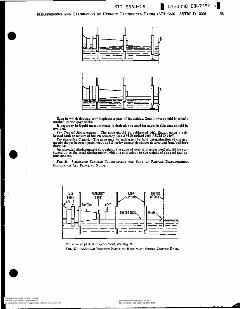
-
OF
STD 2550-b UPRIGHT CYLINDRICAL
5 TANKS
1 O732290 0067572
2550 - ASTM D 1220) 33
Zone in which floating roof displaces a part of its weight. Zone limits should be clearly marked on the gage table.
If accuracy in liquid measurements is desired, the need for gages in this zone should be avoided. For Critical Measuremenîs.-The zone should be calibrated with liquid, using a cali-
brated tank or metera of known accuracy (see API Standard 2555-ASTM D 1406). For Operating Control.-The zone may be calibrated by field determination of the geo-
metric shapes between positions A and B, or by geometric shapes determined from builder?s drawings.
Incremental displacements throughout the zone of partial displacement should be con- tinued up to the total displacement, which is equivalent to the weight of the roof and ap- purtenances.
FIQ. %.-SCHEMATIC DIAQRAM ILLUSTRATINQ THE ZONE OF PARTIAL DISPLACEMENT, COMMON TO ALL FLOATINQ ROOFS.
For. zone of partial displacement, see Fig. 26. FIG. 27.-ANNULAR PONTOON FLOATING ROOF WITH SINGLE CENTER DECK.
Copyright American Petroleum Institute Provided by IHS under license with API Licensee=Aramco HQ/9980755100
Not for Resale, 11/25/2006 02:32:33 MSTNo reproduction or networking permitted without license from IHS
--`,,,`,,,```,,```,``,`,,,`,`,`-`-`,,`,,`,`,,`---

34 STD 2550-65
MEASUREMENT AND CALIBRATION OF UPRIGHT CYLINDRICAL TANKS (API 2550 - ASTM D 1220)
IPPfiRTk, CENTER OF ROOF\ . I
H"A;r;;! 1- OUTET PONTOON 'n CENTER PONTOON \
For zone of partial displacement, see Fig. 26. F I G . %.-LOW-DECK-TYPE FLOATING ROOF WITH CENTER PONTOON.
CENTER OF ROOF I I SEAL 1 GAGE HATCH
Por zone of partial displacement, see Fig. 26. FIQ. ~~.-HIGH-DEcE-TYPE FLOATING ROOF WITHOUT CENTER PONTOON.
I
For zone of partial displacement, see Fig. 26. FIQ. 30.-HIGH-DECE-TYPE FLOATING ROOF WITH CENTER PONTOON.
I$
O
O
Copyright American Petroleum Institute Provided by IHS under license with API Licensee=Aramco HQ/9980755100
Not for Resale, 11/25/2006 02:32:33 MSTNo reproduction or networking permitted without license from IHS
--`,,,`,,,```,,```,``,`,,,`,`,`-`-`,,`,,`,`,,`---
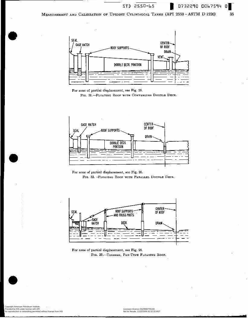
S T D 2550-65 0732290 006759Li 01-
CENTER SEAL
ROOF SUPPORTS
DOUBLE DECK PONTOON - -_ -- - _ - -. - -- _ _ _ _ --
For zone of partial displacement, see Fig. 2G. FIG. 31 .-FLOATING ROOF WITH CONVERGING DOUBLE DECK.
For zone of partial displacement, see Fig. 2G. FIG. %?.-FLOATING ROOF WITH PARALLEL DOUBLE DECK.
CENTER- nc D M C
For zone of partial displacement, see Fig. 26. FIG. 33.-TRUSSED, PAN-TYPE FLOATING ROOF.
Copyright American Petroleum Institute Provided by IHS under license with API Licensee=Aramco HQ/9980755100
Not for Resale, 11/25/2006 02:32:33 MSTNo reproduction or networking permitted without license from IHS
--`,,,`,,,```,,```,``,`,,,`,`,`-`-`,,`,,`,`,,`---
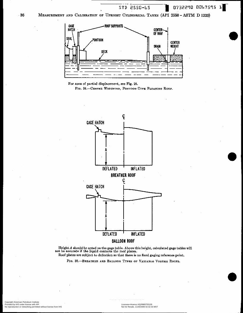
S T D 2550-65 0732290 0067595 36 MEASUREMENT AND CALIBRATION OF UPRIQHT CYLINDRICAL TANKS (API 2550 - ASTM D 1220)
For zone of partial displacement, see Fig. 26. FIQ. 3 4 . x E N T E R WEIGHTED, PONTOON-TYPE FLOATING ROOF.
GAGE
DEFLATED ' INFLATED BREATHER ROOF
GAGE HATCH
A
V DEFLATED INFLATED
BALLOON ROOF Height A should be noted on the gage table. Above this height, calculated gage tables will
Roof plates are subject to deflection so that there is no fixed gaging reference point. not be accurate if the liquid contacts the roof plates.
FIO. 35.-BREATHER AND BALLOON TYPES OF VARIABLE VOLUME ROOFS.
Copyright American Petroleum Institute Provided by IHS under license with API Licensee=Aramco HQ/9980755100
Not for Resale, 11/25/2006 02:32:33 MSTNo reproduction or networking permitted without license from IHS
--`,,,`,,,```,,```,``,`,,,`,`,`-`-`,,`,,`,`,,`---

STD 2550-65 O732290 0067576
MEASUREMENT AND CALIBRATION OF UPRIGHT CYLINDRICAL TANKS (API 2550 - ASTM D 1220) 37
/ROOF IN PARTLY RAISED POSITION r-% #
de#J
GAGE HATCH
- .
DIP
ROOF PLATES
SKIRT
LIQUID (OR FLEXIBLE MEMBRANE) SEAL FIG. %.-LIFTER ROOF SEAL FOR VARIABLE VOLUME
ROOF.
MEMBRANE PEN VENT
MEMBRANE
ON LIQUID
- - I= - - I
I- - -I F I G . 37.-T.’ARlABLE VOLUME ROOF WITH FLEXIBLE MEM-
BRANE IN ROOF DONE.
that eventually move with the roof. The roof itself is deadwood, and as the liquid level rises around the roof, its geometric shape determines how it should be de- ducted. The geometric shape should be taken from the builder’s drawings or meas- ured in the field with the aid of an engi- neer’s level while the roof is resting on its supports.
(e) Gage Measurements.-The heights of the liquid levels a t positions A and B, Fig. 26, should be measured and recorded.
Variable Volume Roofs 27. (a) Variable volume roofs, Figs.
35 to 37, such as breather, balloon, lifter, or flexible membrane, may require special
deadwood measurements for roof parts that are sometimes submerged. When these parts, such as columns, are fixed relative to the tank shell, they should be measured as deadwood in the usual way. When these parts move with the roof and hang down into the liquid, they should be deducted as fixed deadwood with the roof in the lowest position. Details may be secured from the builder or measured in the field.
( b ) Some variable volume roofs have flexible membranes which may float on the surface when the membrane is deflated and the liquid level is high. The floating weight of the membrane displaces a small volume of liquid. Data on the floating weight should be secured from the builder
and supplemented, if necessary, by field observation and measurement.
(e) Some variable volume roofs have liquid seal troughs or other appurtenances which make the upper outside part of the shell inaccessible for outside circumference measurements. Liquid calibration, as de- scribed in API Standard 2555-ASTM D 1406, of this portion of the shell may be made, or ( I ) theoretical dimensions may be taken from the builder’s drawings, or (2) the highest measurable circumferential measurements may be used as a basis for the portion of the tank that cannot be measured. When the procedure in either (1 ) or (2) is used, it should be so indicated on the gage table.
Copyright American Petroleum Institute Provided by IHS under license with API Licensee=Aramco HQ/9980755100
Not for Resale, 11/25/2006 02:32:33 MSTNo reproduction or networking permitted without license from IHS
--`,,,`,,,```,,```,``,`,,,`,`,`-`-`,,`,,`,`,,`---

S T D 2550-65 1 0732240
35 MEASUREMENT A N D C A L I B R A T I O N OF U P R i G H T CYLINDRICAL TANKS (APl 2550 - ASTM D.1220)
WOODEN TANKS
General
28. (a) Wooden tanks may be measured at any time after they have been filled a t least once.
(b) Prior to use, measurement tapes should be checked for accuracy and for required tension, against a certified tape in accordance with the procedure described in Section 5.
(c) A wooden tank should be com- pletely remeasured when i t has been relo- cated, altered, or modified in any way that might change its capacity.
Terminology 29. (a) Hoop Driven (H.D.).-A tank
should be considered to have been hoop driven when there is a break in paint marks across hoops to staves, or in paint marks across threads and nuts on turn- buckles.
(b) Rebuilt (R.B.),-A tank is con- sidered to be rebuilt when it has been wholly or partially dismantled and reas- sembled on the same or a new location.
(c) Moved Bodily (MaB.).-A tank moved to a new location without being dismantled.
(d) Deadwood Change (D.W.C.) .-A change in deadwood which does not affect the tank shell, including:
(e) Concrete in Bottom (CB.).-The addition of concrete or other material to the tank bottom. The condition requires particular attention a t the time of remeas- urement ‘because of its effect on stave height and oil height and on locations of tape pat.hs for circumferential measure- ments.
(f) Strapper’s Depth, or Stave Height. -The perpendicular distance from the top of staves of equal height, used for marking elevations for regular circumferential measurements, to the inside surface of the tank bottom.
(9) Gager’s Depth, or Oil Depth.-The perpendicular distance from the top of the shortest stave to the inside surface of the tank bottom. In the case of a tank with a deck set in (D.S.I.) below the level of the shortest stave, the oil depth is the perpendicular distance from the lowest point on the lower surface of the deck to the inside surface of the tank bottom.
(h) Thickness of Staves.-A simple average of the thickness of individual
/THICKNESS OF STAVE
TOP OF STAVES OF EQUAL HEIGHT
FOURTH REGULAR MEASUREUENT POINT
THIRD REGULAR MEASUREMENT POINT
SECOND REGULAR MEASUREMENT POIWT
~~
------- FIRST REGULAR MEASUREMENT POINT -------
* If the height of the tank, based on the gager’s depth, extends to 1 ft 6 in. or more above the uppermost regular measurement point, an additional regular measurement point should be established a t a distance of 1 f t O in. above the uppermost regular measurement point established by measurements illustrated.
Irregular measurement points, if required, are to be located a t 3-in. intervals above or below .the regular meaaurement points.
FIG. 38.-LOCATIONS OF MEASUREMENTS ON REGULAR TYPE O F WOODEN TANE.
staves, up to 10 in number, to the nearest
(i) Regular-Type Tank.-Wooden stave construction, in the shape of a frustum of a right-angle cone, with staves encircled by hoops.
(i) Eccentric Slope.-Irregularity in slope along length of staves.
(k) Regular Slope.-Constant slope throughout length of staves.
(1) Regular Circumferential Measure- ments.-Circumferential measurements taken at O ft 6 in. above the inside surface of the tank bottom (neglecting the effect of the slope angle), and at successive 2 ft O in. intervals (or 1 ft O in. for barrel or other types) upward along the slope of
1/46 in. the staves [plus the exception described in Section 32(b)].
(m) Irregular Circumferential Meas- urements.-Circumferential measurements taken a t elevations of 3, 6, 9, or 12 in. above or below the points for regular cir- cumferential measurements, as described in Paragraph (1).
Tolerances 30. (a) vertical measurements should
be recorded to the nearest !4 in. (b) Circumferential measurements
should be recorded to the nearest 0.01 ft. (c) Stave thickness should be recorded
to the nearest 446 in. (d) Circumference measurements taken
at different dates, with the same or dif-
Copyright American Petroleum Institute Provided by IHS under license with API Licensee=Aramco HQ/9980755100
Not for Resale, 11/25/2006 02:32:33 MSTNo reproduction or networking permitted without license from IHS
--`,,,`,,,```,,```,``,`,,,`,`,`-`-`,,`,,`,`,,`---

STD 2550-65 I 0732290 0067596 ïc
s
MEASUREMENT AND CALIBRATION OF UPRIGHT CYLINDRICAL TAN^
/THICKNESS OF STAVE
7%
I FIFTH REGULAR - MEASUREMENT POINT 0
I c W
U3 œ W n -- U a c
n
- M I - U3
FOURTH REGULAR MEASUREMENT POINT
THIRD REGULAR MEASUREMENT POINT
SECOND REGULAR MEASUREMENT POINT
c
FIRST REGULAR MEASUREMENT POINT
FIO. 39.-hCATIONS OF MEASUREMENTS ON BARREL OR OTHER TYPES OF WOODEN TANKS.
ferent tapes, and by the same or different personnel, may be considered to be in agreement if results check to or within 0.03 f t per 100 f t of circumference. For a circumference less than 100 ft, the toler- ance of 0.03 f t may be reduced by the ratio of circumference, in feet, to 100 ft.
(e) Any evidence of hoop drive or of tightening of bolted hoops, as indicated, for example, by a severance of paint marks a t hoop edges or a t bolts, should
( b ) Using the strapper’s depth, eleva- tions for regular circumferential measure- ments should be located along the outside surface of staves, lengthwise, a t the fol- lowing elevations above the inside surface of the tank bottom (angle of slope of staves neglected) as shown in Fig. 38:
O f t 6 in. (first regular point) 2 f t 6 in. (econd regular point) 4 ft 6 in. (etc.) 6 f t 6 in.
require that a complete restrapping be 8 ft 6 in. made. 10 f t 6 in.
12 f t 6 in. Previous Data 14 ft 6 in.
etc., except that: If the height of the to be restmpped, tank, based on the gager’s depth, extends
the strapper should make a check with to 1 ft 6 in., or more, above the upper- the original strapping report, if readily most r e d a r Point, then an dditiQnd ava&ble, of infomation such as the fol- regular point should be established at a
distance of 1 ft O in. above the upper- lowing: name of tank orner, lease names, and locations. If dkrepancies. appear, an progreayion shown in this tabulation.
31. When a tank
mo& regular point 88 d e k f i e d by the
explanation should accompany the strap- per’s report. ( c ) Regular measurement points should
be marked on the tank wall in a t least -
vertical Measnrements of RedW-Type four places approximately evenly spaced Wooden Tanks around the tank. 32. (a) The strapper’s depth [Section (d ) Irregular measurement points
should be located, as required, due to ob- structions in the tape paths at regular points, a t distances of 3, 6, 9, or 12 in.
!B(f)] and, for boxed-roofed tanks, the gager’s depth [Section 29(g)] shali be measured and recorded.
(API 2550 - ASTM D 1220) 39
Circumferential Measurements of Rem- lar-Type Wooden Tanks
33. (a) Sequence of measurements may be established to suit existing circum- stances.
( b ) Tape paths should be clean. ( c ) At each measurement elevation the
tape should be positioned at the measure- ment point, brought to proper tension, and the reading taken and recorded. Each such initial reading a t each measurement point should be checked by shifting the tape circumferentially, repositioning, and reapplying the proper tension. A step- over or caliper may be used to span lo- calized obstructions, if convenient. This equipment should be calibrated for the particular tank diameter as described in Section 6 (i). Check readings should be re- peated until agreement has been reached.
(d ) It is recommended that circumfer- ence measurements taken a t irregular points be computed to equivalent regular- point basis before leaving the tank site, as an aid in appraisal of circumference varia- tions relative to slope characteristics of the shell.
(e) Because irregular measurement points are removed from regular meas- urements by increments of 3.in., the dif- ference between regular and irregular measurements must be computed in sec- tions of 3 in. each. Thus, 1 ft 9 in. equals seven sections of 3 in. each; 2 ft O in. equals eight sections of 3 in. each, etc.
Barrel and Other Types of Wooden Tanks 34. (a) Circumference measurements on
all types of wooden tanks, other than the regular type, should be taken a t 1 f t O in. intervals, beginning a t a point O f t 6 in. above the inside surface of the tank bot- tom as shown in Fig.’ 39, If hoops are found to interfere at these locations, measurements should be taken a t points equidistant in 3-in. increments above and below the reguiar points of measurément. The average of these measurements should
taken as the regular measurement. When manholes or other obstructions are encountered at the regular locations, a step-over or caliper of adequate span should be used. When paint lines a t hoop edges or a t tightening bolts have been severed, circumferences should be remeas- ured.
( b ) Thickness of staves should be de- termised as described in Section 29(h).
Copyright American Petroleum Institute Provided by IHS under license with API Licensee=Aramco HQ/9980755100
Not for Resale, 11/25/2006 02:32:33 MSTNo reproduction or networking permitted without license from IHS
--`,,,`,,,```,,```,``,`,,,`,`,`-`-`,,`,,`,`,,`---

S T D 2550-bS 0732240 00b7577 71-
40 MEASUREMENT AND CALIBRATION OF UPRIGHT CYLINDRICAL TANKE) (API 2550-ASTM b 1220)
Deadwood
35. Deadwood in all types of wooden tanks should be determined and located by measurement readings to the nearest '/s in.
UNDERGROUND TANKS Conditione and Procedures for Measure-
ments 36. ( a ) Underground storage tanks may
be constructed of steel, concrete, or other materiais; they may constitute horizontal or vertical cylinders with flat or dished ends, rectangular or irregularly shaped prisms with flat surfam, or other solids bounded by a cdmbination of flat or curved surfaces. In large underground tanks more deadwood may be present than in aboveground tanks of comparable size and shape. It is, therefore, important that deadwood be carefully measured. The following procedures may be used in de- termining the data necessary for the prep- aration of gage tables:
(b) Liquid Calibration.-Probably the most satisfactory method of calibrating underground tanks (initially and later) is by liquid calibration, as described in API Standard 2555-ASTM D 1406.
( c ) Calibration Based on Outside Measurements.-Calibration of under- ground tanks may be completed by fol- lowing the procedures for outside meas- urements specified in this standard for aboveground tanks of the same type, if the method of construction makes this possible. It must be recognized that the placing of earth backñll may result in tank deformations which might appreci- ably affect the tank capacity.
( d ) Calibration Based on Inside Meas- urements.-Calibration of underground tanks may be based on inside measure- ments, The internal measurement proce- dure, as applied to cylindrical or rectan- gular tanks, should be carried out by measuring internal diameters or other di- mensions for later preparation of a table of tank capacities. This involves measure- ment of:
(i) An adequate number of diameters or other dimensions (Note 12) with their approximate position in the tank.
(I) The volume and location of dead- wood; i.e., of any fitting or other object which adds to or subtracts from the space available for liquid.
PLAN GAGING REFERENCE POINT
-------------- --- FOR ELEVATiONS AT WHICH DIAMETERS
SHOULD BE MEASURED, SEE APPROPRIATE FIGURE FOR UPRIGHT CYLINDRICAL STEEL AWEGROUHD TANK OF SIMILAR PLATE
ELEVATION Diameter Measurements:
Minimum number of diameter measurements = D/8, but not less than four measurements, where D = nominal tank diameter, in feet.
Half of the diameter meaaurements should be made with one end of the tape located near the middle of a shell plate; remainder with one end of the tape located near but not closer than 12 in. to a vertical joint.
TANKS. FIG. 40.-LOCATIONS OF MEASUREMENTS ON UPRIGHT CYLINDRICAL STEEL UNDERGROUND
NOTE 12.-When drawings for the tank are available, the diameters and other meas- urements should be compared with those obtained from the drawings, and any meas- urements which Show substantial discrepan- cies on this comparison should be verified. A similar process of check should be em- ployed in all cases in which reliable informa- tion beyond the measurements taken is available.
Diameter Measurements for Upright Cy- lindrical Steel Underground Tanks
37. (a) Diameters should be measured after the tank has been filled a t least once with liquid a t least as dense as it is ex- pected to contain. The usual water test, if made, wiii meet this requirement.
(b) Diameters should be measured with steel tapes which meet the requirements of Section 5.
(c) Diameter measurements should be
taken, as shown in Fig, 40, between dia- metrically opposite pointa so that the measured lines pass through a common center point, and a t the same elevations a t which circumferences are to be meas- ured for aboveground tanks of corre- sponding type. At each such elevation :
(i) A minimum of D/8, but not less than four diameters a t each elevation, should be measured at approximately equal intervals around the tank, where D is the tank diameter expressed in feet.
(I) Half of the diameters should be measured with one end of the tape located near the middle of a shell plate.
(3) Half of the diameters should be measured with one end of the tape located near but not closer than 12 in. to a ver- tical joint,
( d ) If for any reason it is impractical to take measurements a t the positions de-
--
Copyright American Petroleum Institute Provided by IHS under license with API Licensee=Aramco HQ/9980755100
Not for Resale, 11/25/2006 02:32:33 MSTNo reproduction or networking permitted without license from IHS
--`,,,`,,,```,,```,``,`,,,`,`,`-`-`,,`,,`,`,,`---

S T D 2550-65 I 0732290 O067600
MEASUREMENT AND CALIBRATION OF UPRIGHT CYLINDRICAL TANKS (Aï1 2550 - ASTM D ,1220) 41
scribed in Paragraph (c), then the diam- bter should be measured from a point as close to the described position as practi- cable, but not nearer to the horizontal or vertical joints.,The reason for the devia- tion should be recorded in the field notes.
(e) Measurements should be taken with the end of the steel tape attached to a dynamometer, one operator placing the dynamometer on the predeterinined point and the second operator placing a rule end on a point diametrically opposite. The tape should be pulled along the rule until the tension for which the tape ha5 been calibrated is registered on the dynamom- eter. This tension should be not less than 10 lb. A firm grip should be maintained on the rule and tape to prevent any al- teration in their relative positions, the tension should be released, and a reading should be taken on the tape a t that end of the rule which was against the side of the tank. The operation should be re- peated a t the various positions at which measurements are required throughout the tank. The measurements should be re- corded clearly in white chalk on the steel plates in such a manner as to indicate the positions a t which they were taken. [For an alternative procedure, see Paragraphs (4 and (i).]
(f) Each measurement of diameter should be recorded to the nearest 0.005 f t .
( 9 ) Check measurements of diameters multiplied by 3.1416 should not differ by more than the values given in Table I [Section 16(b)].
(h) Corrections for the effect of sag should be applied to the average diam- eter for each course using the following formula :
wzs3 24P2
Correction, in feet = - = KS3
where: P = puil on tape, in pounds. S = span of tape, in feet. W = weight of tape, in pounds per foot.
WZ K = constant for tape = - 24P
Corrections for the effect of stretch are unnecessary because the tension applied is that a t which the tape was standardized. Corrections for the length of the dyna- mometer when registering this pull should be made to the average diameter of each course. The dynamometer length at this
PLAN /GAGING REFERENCE POINT
\TANK BOTTOM: SEE SECTION 23 AND FIG. 22
ELEVATION
I
Diameter Measurementa:
ments, where D = nominal tank diameter, in feet.
tank diameter.
with field sketches of tank.
GROUND TANKS.
Minimum number of diameter measurements = D/8, but not less than four measure-
'Diameter measurements should also be made at locations of offsets or abrupt changes in
Measurements at all locations illustrated should be reported on strapperJs record, along
FIG. 41.-LOCATIONS OF MEASUREMENTS ON UPRIGHT CYLINDRICAL CONCRETE UNDER-
pull should be measured accurately be- fore it is put into use and subsequently checked before and after the calibration of each tank, the final check being made before leaving the tank site.
(i) As an alternative to the procedure outlined in Paragraph (e) , measurements may be made by: (i) establishing plumb lines a few inches distant from the tank wall a t the proper locations; (2) meas- uring the distance between the plumb lines with the tape resting on the tank floor, thus eliminating the need for a sag correction; (3) measuring with a rule the
distances from the plumb lines to the ad- jacent tank walls a t the required eleva- tions; and (4) adding the two correspond- ing short-end measurements to the single center floor measurement to determine the required dimension for each elevation.
(j) If a center column makes imprac- tical a direct measurement of the distance between plumb lines [Paragraph (i)], a circular template may be cut and fitted around the base of the column with points on the circumference of this circle marked to correspond with the radial lines on which diameters are to be measured. The
Copyright American Petroleum Institute Provided by IHS under license with API Licensee=Aramco HQ/9980755100
Not for Resale, 11/25/2006 02:32:33 MSTNo reproduction or networking permitted without license from IHS
--`,,,`,,,```,,```,``,`,,,`,`,`-`-`,,`,,`,`,,`---

42 MEASUREMENT AND CALIBRATION
total diameter may then be found, equal to the diameter of the template plus the two short-end measurements plus two radial measurements between the circum- ference of the template and the plumb lines adjacent to the shell.
Diameter Measurements for Upright Cy- lindrical Concrete Underground Tanks 38. (a) Diameters should be measured
at the following elevations, as shown in Fig. 41 :
(i) 1 ft above the tank bottom. (2) 1 ft below the tank roof. (3) At intermediate elevations not
more than 6 ft apart. (4) At any offsets or abrupt changes
in wall diameter. (b) At each such elevation ä minimum
of D/8, but not less than four diameters, should be measured at approximately equal intervals around the tank, where D is the tank diameter expressed in feet.
(c) If for any reason it is impractical to take measurements a t the positions de- scribed in Paragraphs (a) and ( b ) , then the diameter should be taken as close to the described position as practicable. The reason for the deviation should be re- corded in the field notes.
(d ) Diameters should be measured, re- corded, and corrected as specified for un- derground cylindrical steel tanks in Sec- tion 37.
Measurements for Rectangular Steel or
39. (a) Lengths and widths should be measured a t the following elevations, as shown in Fig. 42 :
Concrete Underground Tanks
(i) 1 ft above the tank bottom. (2) 1 ft below the tank roof. (3) At intermediate elevations not
b o r e than 6 f t apart, unless it can be shown that the walls are vertical, in which case measurements a t intermediate eleva- tions not more khan 12 f t apart are ade- quate.
(4) At any offsets or abrupt changes in waii dimensions,
(b ) At each such elevation: (i) Two width and two length meas-
urements should be made at points 1 f t inside each of the four walls of the tank,
(2) Additional width and length meas- urements (a minimum of one each) should be made a t intermediate points not more than 12 f t apart.
OF UPRIGHT CYLINDRICAL TANKS (API 25G-GSTM D
J
PLAN
1220)
MEASUREMENTS SHOWN IN PLAN SHOULD BE MADE AT EACH ELEVATION
GAGING REFERENCE POINT ì
IV+
*
’ TANK 6OTTOM:SEE SECTION 23 AND FIG. 22 ELEVATION
110”-+ 1 Measurements at Intermediate Elevations:
For vertical sides, * = i2 ft, max. For nonvertical sides, * = 6 f t , max. Length and width measurements should be made at elevations of offsets or abrupt changes
Measurements at all locations illustrated should be reported on strapper’s record, prop- in wall dimensions.
erly identified, along with field sketches of tank.
QROUND TANKS. FIQ. 42.-LOCATIONS OF MEASUREMEÌNTS ON RECTANGULAR STEEL OR CONCRETE UNDER-
(c) If for any reason it is impractical to take measurements at the positions de- scribed in Paragraphs (a) and (b ) , then the length or width should be taken as close to the described position as practi- cable. The reason for the deviation should be recorded in the field notes.
(d ) Length or width should be meas- ured, recorded, and corrected as specified for underground cylindrical steel tanks in Section 37.
(e) Vertical dimensions, plate thick- nesses, dimensions of tanks of special shape, measurements of deadwood, and
any other special measurements, such as those for unstable bottoms, should be made in accordance with procedures de- scribed for aboveground upright cylindri- cai tanks in Sections 8 to 22 and as out- lined for underground tanks in Sections 36 to 39, where applicable.
Calibration Based on Drawings
40. In the event that the calibration procedures described in Section 3 6 ( b ) , ( c ) , and ( d ) cannot be used, gage tables ma.y be prepared from computations
Copyright American Petroleum Institute Provided by IHS under license with API Licensee=Aramco HQ/9980755100
Not for Resale, 11/25/2006 02:32:33 MSTNo reproduction or networking permitted without license from IHS
--`,,,`,,,```,,```,``,`,,,`,`,`-`-`,,`,,`,`,,`---

S T D 2550-b5 0732290 0067602 S r MEASUREMENT AND CALIBRATION OF UPRIGHT CYLINDRICAL TANKS (API 2550-ASTM D 1220) 43
based on the construction drawings and bpecifications of the tank builder.
OUTSIDE INSULATED TANKS Conditions and Procedures for Measure-
ments 41. (a) Insulation may be applied to
any tank so that it becomes impractical to use outside measurements for calibra- tion purposes. The foilowing procedures may be followed in determining the data necessary for the preparation of gage tables :
(b) Liquid Calibration.-Insulated tanks may be calibrated by the introduc- tion of measured quantities of liquid in accordance with API Standard 2555- ASTiM D 1406.
( c ) Calibration Based on Outside Measuremenis.-Calibration of outside in- sulated tanks may be completed before the insulation is applied by following the procedures for outside measurements specified in this standard for aboveground tanks of the same type. The addition of
insulation should not normaiiy affect the accuracy of this calibration.
(d) Calibration Based on Inside Meas- urements.-Calibration of insulated tanks may be based on inside measurements a8 described for underground tanks in Sec- tions 36 to 39.
(e) Calibration Based on Drawings.- Calibration may be based on the data given in the drawings and in the specifi- cations of the tank builder, if none of the methods in Paragraphs (b), (e), or ( d ) can be used.
PART II. TANK CAPACITY CALCULATION PROCEDURES
General
42. Sound engineering and mathemati- cal principles should be used in all calcu- lations. These principles should include those given herein for application to this particular type of work. It should be noted that length measurements may be made by working tapes which may have been calibrated against a standard tape of length based on 68 F. Where this oc- curs, the calculation of gage tables shall mathematically correct such length val- ues to the equivalent 60 F value prior to use.
Gage Tables
43. ( U ) Tank capacities shoiild be ex- pressed in whole gallons, or barrels and decimal parts of a barrel (see Tables VI1 and VI11 in Appendix I ) .
(b) Attention is directed to the fact that tolerances for measurements and cal- culations included in this standard are in- tended to apply to the development of both critical measurements and operating control gage tables (see Section 13). Ad- justments for the effect of any of the variables may be incorporated in gage tables for operating control tanks. It is recommended that gage tables be marked to show adjustments which have been in- corporated therein.
( c ) As a matter of principle, i t is rec- ommended that all newly prepared gage tables show thereon the date on which they are effective. The basis for estab- lishing such a date, in specific cases, is de- pendent upon individual circumstances and the needs of the parties concerned.
However, it is intended that the effective date be established, taking into considera- tion circumstances including but not lim- ited to: (1) the date a new tank was first used; (2) the date an old tank was re- calibrated; and (3) the date agreed upon for purchase, sale, or exchange of product.
Conversion of Outside to Inside Circum- ferences
44. Plate thicknesses used in calcula- tions should be those reported on field measurement records. Values for plate thicknesses taken from drawings may be used where necessary.
Inside circumference (in feet)
= outside circumference (in feet)
?rt
6 - - ... . . ( i )
where : t = steel thickness, in inches.
Significant Figures 45. All incremental or total volume cal-
cidations should be carried to seven sig- nificant figures. Corrections to incremen- tal or total volume calculations need be carried only to the number of significant figures consistent with the seventh in the quantity corrected.
Interpolations 46. Interpolations for determinations of
tank volumes preferably should be made on circumference (or diameter) measure- ments rather than on capacities for given height increments. In the development of operating control gage tables for welded steel tanks, interpolations should be made
between those circumferences (or diam- eters) measured at locations 20 per cent down from the top of the top ring and 20 per cent down from the top of the third ring.
Extrapolation
47. Extrapolation should be avoided if possible. If required, it should be accom- plished by the graphical method or the algebraic method.
Weighted Averages
48. Weighted averages, where applica- ble, rather than simple averages should be used in circumference weightings. If more than two circumferences have been meas- ured for a given tank ring or height seg- ment, and if the individual measurements are representative of different width in- crements, a weighted rather than a simple average should be used in circumferential weightings. Thus, if a ring or height seg- ment has been measured at the top, bot- tom, and center locations, the top and bottom measurements should each be given a weight of one and the center measurement a weight of two in deter- mining the desired weighted average. Weighting of circumference measurements is necessary only in those cases where one or more measurements are made on a given ring a t locations intermediate to those locations illustrated in Figs. 11 to 19, by reason of bulges or other departures from the typical tank shell contour.
Deadwood Deductions 49. All deadwood should be accurately
accounted for as to volume and location, in order to permit adequate allowance for
Copyright American Petroleum Institute Provided by IHS under license with API Licensee=Aramco HQ/9980755100
Not for Resale, 11/25/2006 02:32:33 MSTNo reproduction or networking permitted without license from IHS
--`,,,`,,,```,,```,``,`,,,`,`,`-`-`,,`,,`,`,,`---
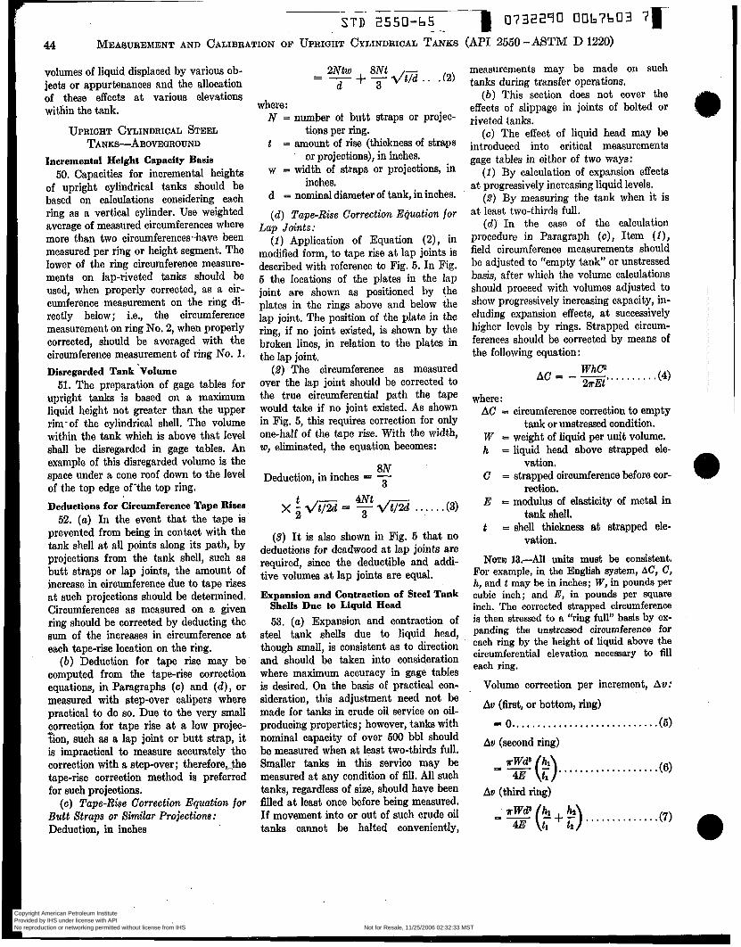
S T D 2550-65 _I 0732240 O067603 71-
44 MEASUREMENT AND CALIBRATION OF UPRIGHT CYLINDRICAL TANKS (API 2550 - M T M D 1220)
volumes of liquid displaced by various ob- jects or appurtenances and the allocation of these effects a t various elevations within the tank.
UPRIGHT CYLINDRICAL STEEL TANKS-ABOVEGROUND
Incremental Height Capacity Basis 50. Capacities for incremental heights
of upright cylindrical tanks should be based on calculations considering each ring as a vertical cylinder. Use weighted average of measured circumferences where more than two circumferences-have been measured per ring or height segment. The lower of the ring circumference measure- ments on lap-riveted tanks should be used, when properly corrected, as a cir- cumference measurement on the ring di- rectly below; i.e., the circumference measurement on ring No. 2, when properly corrected, should be averaged with the circumference measurement of ring No. 1. Disregarded Tank ’Volume
51. The preparation of gage tables for upright tanks is based on a maximum liquid height not greater than the upper rim- of the cylindrical shell. The volume within the tank which is above that level shall be disregarded in gage tables. An example of this disregarded volume is the space under a cone roof down to the level of the top edge of-the top ring. Deductions for Circumference Tape Risee
52. ( a ) I n the event that the tape is prevented from being in contact with the tank shell a t all points along its path, by projections from the tank shell, such as butt straps or lap joints, the amount of increase in circumference due to tape rises a t such projections should be determined. Circumferences as measured on a given ring should be corrected by deducting the sum of the increases in circumference a t each tape-rise location on the ring.
( b ) Deduction for tape rise may be computed from the tape-rise correction equations, in Paragraph ( c ) and (d ) , or measured with step-over calipers where practical to do so. Due to the very small correction for tape rise a t a low projec- tion, such aa a lap joint or butt strap, it is impractical to measure accurately the correction with a step-over ; therefore,the tape-rise correction method is preferred for such projections.
( c ) Tape-Rhe Correction Equation for Butt Straps or Similar Projections: Deduction, in inches
4
2Ntw 8Nt = - + -j- dt2 .. . (2 )
d
where: N = number of butt straps or projec-
tions per ring. t = amount of rise (thickness of straps
or projections), in inches. w = width of straps or projections, in
inches. d = nominal diameter of tank, in inches.
( d ) Tape-Rise Correction Equation for Lap Joints:
(1) Application of Equation (2), modified form, to tape rise at lap joints is described with reference to Fig. 5. In Fig. 5 the locations of the plates in the lap joint are shown as positioned by the plates in the rings above and below the lap joint. The position of the plate in the ring, if no joint existed, is shown by the broken lines, in relation to the plates in the lap joint.
(2) The circumference as measured over the lap joint should be corrected to the true circumferential path the tape would take if no joint existed. As shown in Fig. 5, this requires correction for only one-half of the tape rise. With the width, w, eliminated, the equation becomes:
8N Deduction, in inches = - 3
. * (3)
(3) It is also shown in Fig. 5 that no deductions for deadwood a t lap joints are required, since the deductible and addi- tive volumes a t lap joints are equal.
Expansion and Contraction of Steel Tank Shells Due to Liquid Head 53. ( a ) Expansion and contraction of
steel tank shells due to liquid head, though small, is consistent as to direction and should be taken into consideration where maximum accuracy in gage tables is desired. On the basis of practical con- sideration, this adjustment need not be made for tanks in crude oil service on oil- producing properties; however, tanks with nominal capacity of over 500 bbl should be measured when at least two-thirds full. Smaller tanks in this service may be measured at any condition of fill. Ail such tanks, regardless of size, should have been filled a t least once before being measured. If movement into or out of such crude oil tanks cannot be halted conveniently,
measurements may be made on such tanks during transfer operations.
( b ) This section does not cover the effects of slippage in joints of bolted or riveted tanks.
( c ) The effect of liquid head may be introduced into critical measurements gage tables in either of two ways:
(1) By calculation of expansion effects a t progressively increasing liquid levels.
(2) By measuring the tank when it is a t least two-thirds full.
( d ) In the case of the calculation procedure in Paragraph ( c ) , Item (I), field circumference measurements should be adjusted to “empty tank” or unstressed basis, after which the volume calculations should proceed with volumes adjusted to show progressively increasing capacity, in- cluding expansion effects, a t successively higher levels by rings. Strapped circum- ferences should be corrected by means of the following equation:
* . * . . .(4) Whc2 27rEt * * * *
A C = - -
where: AC = circumference correction to empty
t m k or u n s t r e d condition. W = weight of liquid per unit volume. h = liquid head above strapped ele-
C = strapped circumference before cor-
E = modulus of elasticity of metal in
t = shell thickness at strapped ele-
NOTE 13,-All units must be consistent. For example, in the English aystem, AC, c, h, and t may be in inches; W, in pounds per cubic inch; and E, in pounds per square inch. The corrected strapped circumference is then stressed to a “ring full” basis by ex- panding the unstressed circumference for each ring by the height of liquid above the circumferential elevation necessary to fill each ring.
Volume correction per increment, Av:
Au (first, or bottom, ring)
vation,
rection.
tank shell.
vation.
= o.. . . . . , . . . * . . , . . . . * . * . . * . . . . ( 5 )
Au (second ring)
, , . . . . . . . . . . . . . . . . .(6)
Au (third ring)
TW@ hi 5 -jjj- (t; + ?). . * . . . . . . . . a . .(7)
Copyright American Petroleum Institute Provided by IHS under license with API Licensee=Aramco HQ/9980755100
Not for Resale, 11/25/2006 02:32:33 MSTNo reproduction or networking permitted without license from IHS
--`,,,`,,,```,,```,``,`,,,`,`,`-`-`,,`,,`,`,,`---

S T D 2550-65 I 0732290 0067604 9 1 -
MEASUREMENT AND CALIBRATION OF UPRIGHT CYLINDRICAL TANKS (MI 2550 - ASTM D 1220) 45
Av (nth ring)
where: Au = additional tank volume re-
sulting from tank shell expansion due to in- creased head of an in- crement one unit deep above the ring.
W = weight of liquid per unit volume.
d = nominal tank diameter. E = modulus of elasticity of
metal in tank shell. hl , hz , etc. = height of shell rings. t i , t 2 , etc. = thickness of shell rings.
NOTE 14.-All units must be consistent. For example, in the English system, A v may be in cubic inches; W, in pounds per cubic inch; d, h, and t, in inches; and E, in pounds per square inch. The increment correspond- ing to A v is 1 in. If the gage table is made in %-in. increments, A v must be divided by 4.
(e) In the event that it is not desired to produce a gage table which incorporates the expansion effects calculated at M e r - ing liquid levels, as mentioned in Para- graph (c), Item '(í), the gage table may be based on field measurements taken when the tank is a t least two-thirds f d , as stated in Paragraph (c), Item (2 ) .
( f ) For operating control, use either of the two procedures noted in Paragraph (c), or, alternatively, base the gage table on measurements taken a t any condition of fill desired, to conform with tank own- ner's general practice for tanks in this category, and omit the effect of tank ex- pansion and contraction from the gage table.
Expansion and Contraction of Steel Tank Shells Due to Temperature
54. Expansion and contraction of un- heated steel tank she& may be disre- garded. Correction for expansion or con- traction wiii not be necessary, except when very accurate measurements are re- quired of the contenta of heated tanks. On the basis of practical consideration, this adjustment need not be made for tanks in crude oil service on oil-producing prop- erties. If this adjustment is to be made, then, in the case of strappings made a t cold nonservice temperatures of tanks which wiii be heated in normal service, it
may be necessary to estimate the service temperature and compute volume correc- tions for expansion of the tank shell due to the increase in temperature. Such es- timates of temperature should be checked after tanks are in service. The volume cor- rection procedure for computing the vol- ume to be added to the total volume computed for the tanks from strapping in the unheated condition is as follows:
Cross-sectional area correction,
K = 1 + 12.4 X lO-"At,
+ 4.0 x A%. .(9)
where : At, = steel temperature minus 60 F.
(All t.ank strapping circumference meas- urements for steel tanks are a t 60 F.)
(1) For noninsulated metal tanks, the temperature of the shell may be taken, in general, as the mean of the adjacent liquid and ambient temperatures on opposite sides a t the same location. In which case:
. . . . . ._. . . . (10) t, = - tL + t A
2
where: t L = liquid temperature. t l = ambient temperature.
(2) For insulated metal tanks, the temperature of the shell may be taken as closely approximating the adjacent liquid temperature. In which case, t, = tr, .
I n applying these principles to upright cylindrical tanks, the horizontal cross-sec- tional area may be taken as a function of tank calibration. The third dimension, height, needed to generate volume is a function of gaging and should be con- sidered separately. The volumes reflected on tank tables are derived from area times incremental height. Therefore, K- factors for correction of areas have the same ratio as volume corrections and may be applied directly to ta< table volumes. The coefficient determined from mua- tion (9) is predicated on a thermal expan- sion for low-carbon steel per degree Fahr- enheit. For other than low-carbon steel, the coefficient should be corrected by the ratio of the coefficient of low-carbon steel and the actual metal used at actual tem- perature.
If the tank shell is aluminum a t a tem- perature of 180 F, from the values of a.,, -in the following tabulation, the ratio of
K. (aluminum) t o K, (steel) would be:
o.oooo13o Ka = KI X 0.0000065
Tank Shell Temperature, Value of am t , "F per "F
Steel
-70 to -21 0.0000060 0.0000061 -20 to +28
+29 to. 78 0.0000062 79 to 128 0.0000063 129 to 177 0.0000064 178 to 227 0.0000065 228 to 276 0.0000066 277 to 326 0.0000067
0.0000068 327 to 376 377 to 425 0.0000069
-70 to -11 o.oooo122 o.oooo124 -10 to i-49
+.W tn 1M O.oooO126
Aluminum
, - - - - - - - 110 to 169 . ö.ooool% 170 to 229 0.m130 230 to 289 O.ooOo132
0.m134 290 to 349 350 t o 409 O. oooO136
where : am = the mean coefficient of linear ex-
pansion between temperatures, t, and 60 F.
Effect of Tilt on Cylindrical Portion of Tank 55. ( a ) The liquid surface in a tilted
cylindrical tank is elliDtical in shape, rather than circular, and the capacity per unit of gaging height is greater than would be the case if the tank were t d y upright, For procedures relative to cali- bration of tank bottom characteristics, reference should be made to Section 22.
(b) For critical measurements, the amount of tilt in shell height should be measured. For tanks tilted less than one part in 70 parts, the error in a "vertid" gage table for the cylindrical portion will be less than 0.01 per cent by volume, and the effect may be' disregarded, If the amount of tilt is 1 in 70, or more, the vertical gage table should be adjusted to a zero-tilt basis. The following equation may be used to determine the percentage volume correction due to tilt:
Volume correction, per cent = 100 (4- - 1). .(li)
where : m = amount of tilt per foot of shell
height, in feet (or decimal part thereof).
The following tabulation shows the vol- ume correction in per cent for various amounts of tilt:
Copyright American Petroleum Institute Provided by IHS under license with API Licensee=Aramco HQ/9980755100
Not for Resale, 11/25/2006 02:32:33 MSTNo reproduction or networking permitted without license from IHS
--`,,,`,,,```,,```,``,`,,,`,`,`-`-`,,`,,`,`,,`---
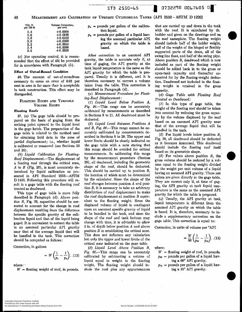
S T D 2550-b5 0732270 00b7b05 O r
(API 2550-ASTM' D 1220) 46 MEASUREMENT AND CALIBRATION OF UPRIGHT CYLINDRICAL TANKS
nit, ft Volume Correction, per 100 ft per cent
1.4 +0.0098 1.6 +0.0128 1.8 +0.0162 2.0 +O.o200 2.2 +0.0242 2.4 +0.0288 2.6 +0.0338
(c) For operating control, it is recom- mended that the effect of tilt be provided for in accordance with Paragraph ( b ) . Effect of Out-of-Round Condition
56. The amount of out-of-roundness necessary to cause an error of 0.01 per cent in area is far more than is acceptable in tank construction. This effect may be disregarded.
FLOATING ROOFS AND VARIABLE VOLUME ROOFS
Floating Roofs 57. ( a ) The gage table should be pre-
pared on the basis of gaging from the striking point upward to the liquid level in the gage hatch. The preparation of the gage table is related to the met.hod used for obtaining field data in the zone of partial displacement; i.e., whether liquid is caiibrated or measured (see Sections 25 and 26).
( b ) Liquid Calibration for Floating- Roof Displacement .-The displacement of a floating roof through the critical zone, A to B (Fig. 26), is most accurately de- termined by liquid calibration as pre- sented in API Standard 2555-ASTM D 1406. Following this procedure will re- sult in a gage table with the floating roof treated as deadwood.
This type of gage table is more fully described in Paragraph ( d ) . Above posi- tion B, Fig. 26, capacities should be cor- rected to account for the change in roof displacement resulting from the difference between the specific gravity of the cali- bration liquid and that of the liquid being gaged. It is convenient to correct the table to an assumed particular API gravity near that of the average liquid that wili be handled in the tank. This correction should be computed as follows :
Correction, in gallons
where: . W = floating weight of roof, in pounds,
p . = pounds per galion of the calibra-
pa = pounds per gaìion of a liquid hav- ing the assumed particular API gravity on which the table is based.
. tionìiquid.
After correction to an assumed API gravity, the table is accurate only if, at time of gaging, the API gravity at the tank liquid Rmperature is the same as the API gravity for which the table is pre- pared. Usualiy it is different, and it is therefore necessary to. correct a volume taken from the table. This correction is described in Paragraph (d ) .
( e ) Measurement Procedure for Float- ing-Roof Displacement :
( 1 ) Liquid Level Below Position A, Fig. 26.-This range can be accurately calibrated by measurements as described in Sections 8 to 21. All deadwood must be deducted.
(2) Liquid Level Between Positions A and B, Fig. 2 6 . T h i s range cannot be ac- curately calibrated by measurements de- scribed in Sections 8 to 20. The upper and lower limits should be clearly indicated on the gage table with a note stating that this range should be avoided for critical measurements. In calibrating this range by the measurement procedure (Section 26), all deadwood, including the geometric shape of the roof, should be deducted. This should be carried up to position B , the location of which must be determined by the calculator. Since the shape of the roof changes between position A and posi- tion B, it is necessary to take an arbitrary distribution of roof displacement to make the roof displacement a t position B equiv- alent to the floating weight. Since the displaced volume of liquid is contingent upon an assumed specific gravity of liquid to be handled in the tank, and since the shape of the roof and tank bottom may change with time, it is advisable to allow 2 in. of depth below position A and above position B in establishing the critical zone. This does not influence any calculation but only the upper and lower limits of the critical zone indicated on the gage table.
(3) Liquid Level Above Position B, Fig. %%.-This range can be accurately calibrated by subtracting a volume of liquid equal in weight to the floating weight. The floating weight should in- clude the roof plus any appurtenances
that are carried up and down in the tank with the roof. It is calculated by th; builder and given on the drawings and OLL
the roof nameplate, The floating weight should include half of the ladder weight, half of the weight of the hinged or flexibly supported parts of the drain, all of the swing line float, and half of the swing pipe. Above position B, deadwood which is now included as part of the floating weight should be added back in to the gross or open-tank capacity and thereafter ac- counted for by the floating-weight deduc- tion. Deadwood not included in the float- ing weight is retained in the gross capacity.
(d ) Gage Table with Floating Roof Treated as Deadwood:
( 1 ) In this type of gage table, the weight of the floating roof should be taken into account by reducing the gross capac- ity by the volume displaced by the roof based on an assumed API gravity near that of the average liquid that will be handled in the tank,
(2) For liquid levels below position B, Fig. 26, all deadwood should be deducted as it becomes immersed. This deadwood should include the floating roof itself based on its geometric shape,
(3) For values above position B, the gross volume should be reduced by a vol- ume equal to the floating weight divided by the weight per unit volume of a liquid having an assumed API gravity. These net values are given directly in the gage table. They are correct only if, at time of gag- ing, the API gravity a t tank liquid tem- perature is the same as the assumed API gravity for which the table is prepared,
(4 ) Usually, the API gravity at tank. liquid temperature is different from the assumed API gravity on which the table is based. It is, therefore, necessary to in- clude a supplementary correction on the gage table. This correction is equal to:
Correction, in units of volume per "API
= (L - '). .(13) 50 PM) P I O
where : W = floating weight of roof, in pounds. pa = pounds per galion of a liquid hav-
ing a 60" API gravity. plo = pounds per gallon of a liquid hav-
~g a 10" API gravity.
Copyright American Petroleum Institute Provided by IHS under license with API Licensee=Aramco HQ/9980755100
Not for Resale, 11/25/2006 02:32:33 MSTNo reproduction or networking permitted without license from IHS
--`,,,`,,,```,,```,``,`,,,`,`,`-`-`,,`,,`,`,,`---
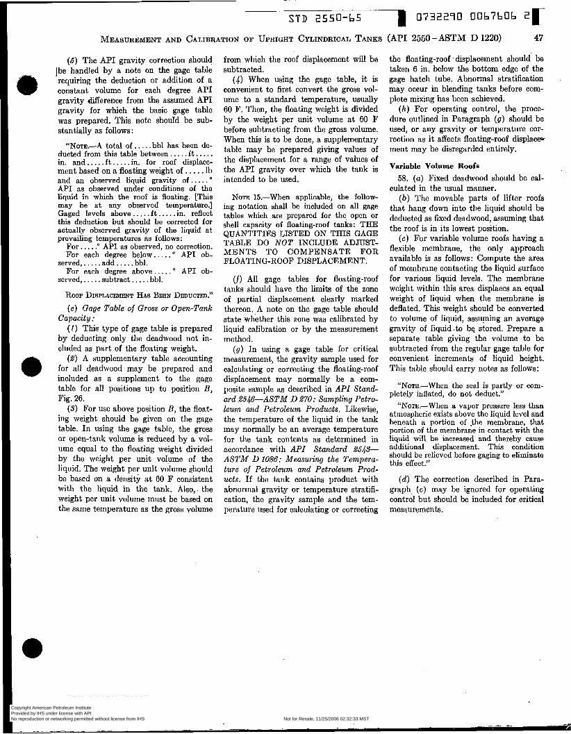
S T D 2550-65 I 0732290 OObïbOb 2 r
47 MEASUREMENT AND CALIBRATION O F UPRIGHT CYLINDRICAL TANKS (API 2550 -MTM D 1220)
(5) The API gravity correction should Ibe handled by a note on the gage table requiring t.he deduction or addition of a constant volume for each degree API gravity difference from the assumed API gravity for which the basic gage table was prepared. This note should be sub- stantially as follows:
“NoTE.-A total of . . . . . bbl has been de- ducted from this table between.. . . . f t . . . . . in. and. .... f t .. .. .in. for roof displace- ment based on a floating weight of . , . . . Ib and an observed liquid gravity of . . . . . O
API as observed under conditions of the liquid in which the roof is floating. [This may be at any observed temperature.] Gaged levels above.. . . . f t . . . . .in. reflect this deduction but should be corrected for actually observed gravity of the liquid at prevailing temperatures as follows:
For.. . . .‘ API as observed, no correction. For each degree below. .. . . O API ob-
For each degree above . . . . . O API ob- served,. . . . . add.. . . . bbl.
served,. . . . .subtract.. . . . bbl.
ROOF DISPLACEMENT HAS BEEN DEDUCTED.” ( e ) Gage Table of Gross or Open-Tank
Capacity : ( 1 ) This t.ype of gage table is prepared
by deducting only the deadwood not in- cluded as part of the floating weight.
(2) A supplementary table accounting for all deadwood may be prepared and included as a supplement to the gage table for all positions up to position B , Fig. 26.
(3) For use above position B, the float- ing weight should be given on the gage table. I n using the gage table, the gross or open-tank volume is reduced by a vol- ume equal to the floating weight divided by the weight per unit volume of the liquid. The weight per unit volume ahould be based on a density a t 60 F consistent with the liquid in the tank. Also,. the weight per unit volume must be based on the same temperature as the gross volume
from which the roof displacement will be subtracted.
(4) When using the gage table, i t is convenient to first convert the gross vol- ume to a standard temperature, usually 60 F. Then, the floating weight is divided by the weight per unit volume a t 60 F before subtracting from the gross volume. When this is to be done, a supplementary table may be prepared giving values of the displacement for a range of values of the API gravity over which the tank is intended to be used.
NOTE 15.-When applicable, the follow- ing notation shall be included on all gage tables which are prepared for the open or shell capacity of floating-roof tanks: THE QUANTITIES LISTED ON THIS GAGE
MENTS TO COMPENSATE FOR FLOATING-ROOF DISPLACEMENT.
TABLE DO NOT INCLUDE ADJUST-
(f) All gage tables for floating-roof tanks should have the limits of the zone of partial displacement clearly marked thereon. A note on the gage table should state whether this zone was calibrated by liquid calibration or by the measurement method.
(9 ) In using a gage table for critical measurement, the gravity sample used for calculating or correcting the floating-roof displacement may normally be a com- posite sample as described in API Stund- ard 2546-ASTM D 270: Sampling Petro- leum and Petroleum Products. Likewise, the temperature of the liquid in the tank may normally be an average temperature for the tank contents as determined in accordance with API Standard 2543- A S T M DlO86: Measuring the Tempera- ture of Petroleum and Petroleum Prod- ucts. If the tank contains product with abnormal gravity or temperature stratifi- cation, the gravity sample and the tem- perature used for calculating or correcting
the floating-roof displacement should be taken 6 in. below the bottom edge of the gage hatch tube. Abnormal stratification may occur in blending tanks before com- plete mixing has been achieved.
( h ) For operating control, the proce- dure outlined in Paragraph ( 9 ) should be used, or any gravity or temperature cor- rection as i t affects floating-roof displace- ment may be disregarded entirely.
Variable Volume Roofs 58. ( a ) Fixed deadwood should be cal-
culated in the usual manner. ( b ) The movable parts of lifter roofs
that hang down into the liquid should be deducted as fixed deadwood, assuming that the roof is in its lowest position.
(c) For variable volume roofs having a flexible membrane, the only approach available is as follows: Compute the area of membrane contacting the liquid surface for various liquid levels. The membrane weight within this area displaces an equal weight of liquid when the membrane is deflated. This weight should be converted to volume of liquid, assuming an average gravity of liquid .to be stored. Prepare a separate table giving the volume to be subtracted from the regular gage table for convenient increments of liquid height. This table should carry notes as follows:
“NoTE.-When the seal is partly or com- pletely inflated, do not deduct.”
“NoTE.-When a vapor pressure less than atmospheric exists above the liquid level and beneath a portion of ,the membrane, that portion of the membrane in contact with the liquid will be increased and thereby cause additional displacement. This condition should be relieved before gaging to eliminate this effect.”
(d ) The correction described in Para- graph (c) may be ignored for operating control but should be included for critical measurements.
Copyright American Petroleum Institute Provided by IHS under license with API Licensee=Aramco HQ/9980755100
Not for Resale, 11/25/2006 02:32:33 MSTNo reproduction or networking permitted without license from IHS
--`,,,`,,,```,,```,``,`,,,`,`,`-`-`,,`,,`,`,,`---
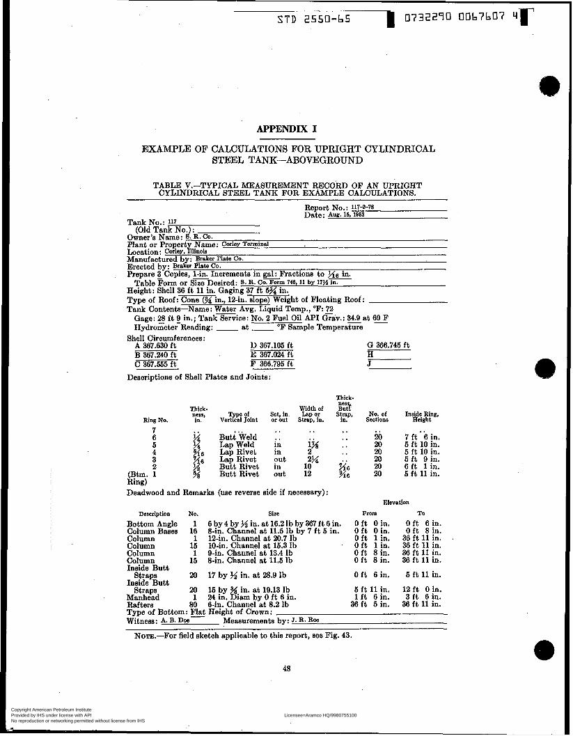
APPENDIX I
EXAMPLE OF CALCULATIONS FOR UPRIGHT CYLINDRICAL STEEL TANK-ABOVEGROUND
TABLE v.-TYPICAL MEASUREMENT RECORD OF AN UPRIGHT CYLINDRICAL STEEL TANK FOR EXAMPLE CALCULATIONS.
~~
Report No.: 117-2-78 Date: Aue. 16, i963
Tank No.: 117
Owner?s Name: 8. R - Co. Plant or Propert Name: C o r k Terminal
Manufactured by: B d e r Plate CO.
Prepare 3 Copies, + Increments in g&Fractions to f i 6 in. Table Form or Size Desired: S. R. Co. Form 746 , i i by 17H in.
Height: Shell 36 ft 11 in. Gaging 37 f t 5% in. Type of Roof: Cone (H in., 12-in. slope) Weight of Floating Roof : Tank Contents-Name: W A r Avg. Liquid Temp., O F : E2
(Old Tank No.) :
Location: coriey, %linois
Erected by: Braker Plate Co.
Gage: 28 - f t g in.; Tank Service: No. 2 Fuel Oil API Grav.: 34.9 at 60 - F Hydrometer Reading: - at - O F Sample TemperaGe
A 367.630 f t D 367.105 f t G 366.745 f t B 367.240 f t E 367.024 f t H c 367.555 f t F 366.795 f t J
Shell Circumferences:
Descriptions of Shell Plates and Joints:
Thick- ne%
Thick- Width of Butt Few, Typeof Set in Lapor Strap, No: of Inside Ring,
Ring No. in. Vertical Joint or hut Strap, in. in, Sections Height
7 6 5 4 3 2
(Btm. 1 Ring)
Butt ?Weld Lap Weld Lap Rivet Lap Rivet Butt Rivet Butt Rivet
.. .. in in
in out
put
.. i% 2?4 2
10 12
*. ..
I .
w 6 946
9 .
20 20 20 20 20 20
7 it * 6 in. 5 ft 10 in. 5 ft 10 in. 5 f t 9 in. 6 f t 1 in. 5 f t 11 in.
Deadwood and Remarks (use reverse side if necessary) : Elevation
Description No. size From To
Bottom Angle 1 6 by 4 by >d in. at 16.2 lb by 367 f t 6 in. O f t O in. O f t 6 in. Column Bases 16 8-in. Channel at 11.5 lb by 7 ft 5 in. O f t O in. O f t 8 in. Column 1 12-in. Channel at 20.7 lb O f t 1 in. 36 ft 11 p. Column 15 10-in. Channel at 15.3 lb ? O f t 1 in. 36 f t 11 in. Column 1 9-in. Channel a t 13.4 lb O f t 8 in. 36 f t 11 in. Column 15 8-in. Channel a t 11.6 lb O f t 8 in. 36 f t 11 in. Inside Butt
Straps 20 17 by W in. at 28.9 Ib O f t 6 in. 5 ft 11 in. Inside Butt
Straps 20 15 by %.in. at 19.13 lb 5 f t 11 in. 12 f t O in. Manhead 1 24 in. Diam by O f t 6 in. 1 f t 6 in. 3 ft 6 in. Rafters 80 6-in. Channel at 8.2 lb 36 ft 5 in. 36 f t 11 in. Type of Bottom: F&t Height of Crown: Witnm : A. B. DOE Measurements by: Ja R- Roa
Nom.-For field sketch applicable to this report, see Fig. 43.
48
Copyright American Petroleum Institute Provided by IHS under license with API Licensee=Aramco HQ/9980755100
Not for Resale, 11/25/2006 02:32:33 MSTNo reproduction or networking permitted without license from IHS
--`,,,`,,,```,,```,``,`,,,`,`,`-`-`,,`,,`,`,,`---

FIXED GAGING
115 DOWN 366.74> PLATE HEIGHT 366.795
367.024' I FT DOWN
367.105 '
362555'
367.240'
367.630' Composite Construction io Illusiraie:
Riveted In-and-Out Arrangement. Riveted Shingled Arrangement. Butt-welded Arrangement. NoTE.-The tank shell illustrated above may not be encountered in actual service. It ie
used only to illustrate the different aspects to computations which are contained in the example calculations.
FIQ. 43.-UPRIQHT CYLINDRICAL TANK, COMPOSITE CONSTRUCTION.
S T D 2550-bS 0732240 0067608 b
MEASUREMENT AND CALIBRATION OF UPRIGHT CYLINDRICAL TANKS (API 2550 - ASTM D 1220) 49
O
O
-- - _ _ I - - - _- - __ --
Copyright American Petroleum Institute Provided by IHS under license with API Licensee=Aramco HQ/9980755100
Not for Resale, 11/25/2006 02:32:33 MSTNo reproduction or networking permitted without license from IHS
--`,,,`,,,```,,```,``,`,,,`,`,`-`-`,,`,,`,`,,`---
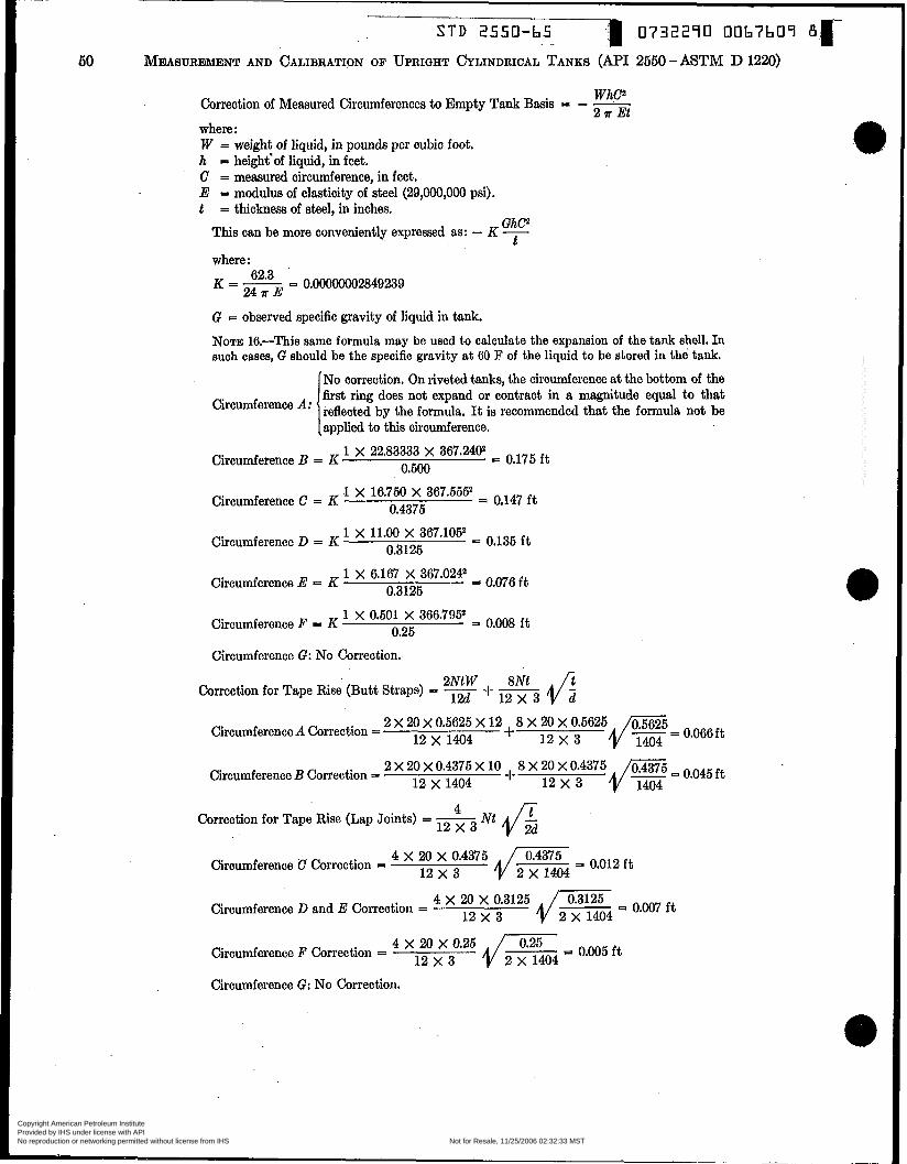
0732290 00b7b09 B r S T D 2550-b5
50 MEIASUREMENT AND CALIBRATION OF UPRIGHT CYLINDRICAL TANKS (API 2550 - ASTM D 1220)
WhC2 Correction of Measured Circumferences to Empty Tank Basis = - -
2 a Et where : W = weight of liquid, in pounds per cubic foot. h = height'of liquid, in feet. C = measured circumference, in feet. E = modulus of elssticity of steel (29,000,000 psi). t = thickness of steel, in inches.
GhO This can be more conveniently expressed as: - K - t
where : K = - 62'3 = 0.00000002849239
!%TE G = observed specific gravity of liquid in tank.
NOTE 16.-This same formula may be used to calculate the expansion of the tank shell. In such cases, G should be the specific gravity a t 60 F of the liquid to be stored in the tank.
No correction. On riveted tanks, the circumference at the bottom of the first ring does not expand or contract in a magnitude equal to that
applied to this circumference. reflected by the formula. It is recommended that the formula not be
1 x 22.83333 X 367.2402 0.500
o.175 ft Circumference B = K
1 X 16.750 X 367.5552 i o,147 ft 0.4375
Circumference C = K
1 X 11.00 X 367.1052 = o,135 ft 0.3125
Circumference D = K
1 X 6.167 X 367.0242 = o.o76 ft 0.3125
Circumference E = K
1 X 0.501 X 366.795* = o,008 ft 0.25 Circumference F = K
Circumference G: No Correction.
Correction for Tape Rise (Butt Straps) =
I/= = 0.066ft 2 X 20 X 0.5625 X 12 + 8 X 20 X 0.5625
12 X 1404 12 x 3
2 X 20 X 0.4375 X 10 8 X 20 X 0.4375 12 x 1404 -k 1 2 x 3
Circumference A Correction =
Circumference B Correction =
Correction for Tape Rise (Lap Joints) = - Nt 12 x 3
4 X 20 X 0.4375 12 x 3
Circumference C Correction =
12 x 3 Circumference D and E Correction =
20 dEi 3 O.C)05 ft 12 x 3
Circumference F Correction =
Circumference G: No Correction.
Copyright American Petroleum Institute Provided by IHS under license with API Licensee=Aramco HQ/9980755100
Not for Resale, 11/25/2006 02:32:33 MSTNo reproduction or networking permitted without license from IHS
--`,,,`,,,```,,```,``,`,,,`,`,`-`-`,,`,,`,`,,`---
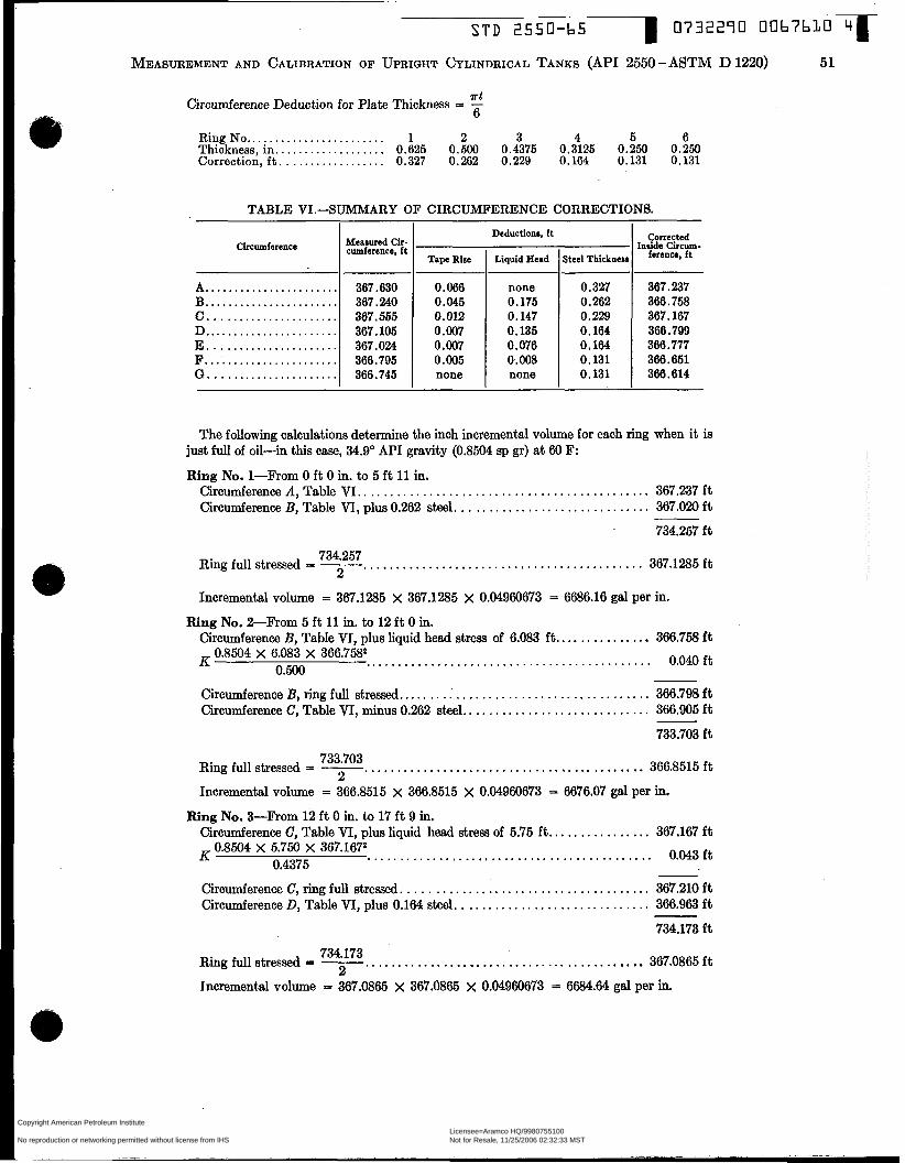
S T D 2550-65 0732290 0 0 b i b L O ~ ~ -
A.. ..................... B . . ..................... C.. .................... D ....................... E. ..................... F... .................... G.. ....................
MEASUREMENT AND CALIBRATION OF UPRIGHT CYLINDRICAL TANKS (API 2550 - ASTM D 1220) 51
367.630 367.240 367.555 367.105 367.024 366.795 366.745
rt Circumference Deduction for Plate Thickness = - 6
Ring No ........................ 1 2 3 4 5 6 Thickness, in.. . . . . . . . . . . . . . . . . . 0.625 0.500 0.4375 0.3125 0.250 0.250 Correction, f t . . . . . . . . . . . . . . . . . . 0.327 0.262 0.229 0.164 0.131 0.131
TABLE VI.SUMMARY OF CIRCUMFERENCE CORRECTIONS.
Measured Cu- cumference, ft Circumference
Tape Rise
0.066 0.045 0.012 0.007 0.007 0.005 none
Deductions, ft
Liquid Head
none 0.175 O. 147 0.135 0.076 0.008 none
~~
Steel Thickneu
0.327 O. 262 0.229 0.164 0.164 0.131 0.131
Corrected inside Circum-
ferencr. ft
367.237 366.758 367.167 366.799 366.777 366.651 360.614
The following calculations determine the inch incremental volume for each ring when it is just full of oil-in this case, 34.9' API gravity (0.8504 sp gr) a t 60 F:
Ring No. 1-From O ft O in. to 5 ft 11 in. Circumference A , Table VI.. ........................................... 367.237 ft Circumference B, Table VI, plus 0.262 steel. ............................. 367.020 ft
734.257 f t
734.257 Ring full stressed = - ........................................... 367.1285 ft
Incremental volume = 367.1285 x 367.1285 x 0.04960673 = 6686.16 gal per in.
Circumference B, Table VT, plus liquid head stress of 6.083 f t . . ............. 366.758 f t 0.040ft K
Circumference B, ring full stressed.. ..................................... 366.798 f t Circumference C, Table VI, minus 0.262 steel., ........................... 366.905 ft
733.703 f t
Ring No. &From 5 ft 11 in. to 12 ft O in.
0.8504 X 6.083 X 366.75tP 0.500 ............................................
366.8515ft Ring full stressed = - ........................................... 733.703 2
Incremental volume = 366.8515 x 366.8515 x 0.04960673 = 6676.07 gal per in.
Ring No. %From 12 f t O in. to 17 f t 9 in. Circumference C, Table VI, plus liquid head stress of 5.75 ft.. .............. 367.167 ft
0.043ft 0.8504 X 5.750 X 367.1672 0.4375
............................................ R
Circumference C, ring ful l stressed. ..................................... 367.210 ft Circumference D, Table VI, plus 0.164 steel. ............................. 366.963 f t
734.173 f t
734.173 Ring full stressed = - ........................................... 367.0865ft
1ncrement.d volume = 367.0865 x 367.0865 x 0.04960673 = 6684.64 gal per in.
Copyright American Petroleum Institute Provided by IHS under license with API Licensee=Aramco HQ/9980755100
Not for Resale, 11/25/2006 02:32:33 MSTNo reproduction or networking permitted without license from IHS
--`,,,`,,,```,,```,``,`,,,`,`,`-`-`,,`,,`,`,,`---

S T D 2550-b5 0732290 00b7blL b r
52 MEASUREMENT AND CALIBRATION OF UPRIQHT CYLINDRICAL TANKS (MI 2550 - ASTV D 1220)
Ring No. P R o m 17 ft 9 in. to 23 ft 7 in. Circumference D, Table VI, plus liquid head stress of 5.833 ft.. ............. 366.799 ft
0.061 ft 0.8504 X 5.833 X 366.799 0.3125
............................................ K .
Circumference D, ring full stressed. ..................................... 366.860 ft Circumference E, Table VI, plus liquid head stress of 1.00 f t . . .............. 366.777 ft
0.010ft 0.8504 X 1.00 X 366.7772
0.3125 ............................................. K
Circumference E, ring full stresed ....................................... 366.787 ft Circumference D, ring fuli stressed ...................................... 366.860 f t
733.647 f t
366.8235ft 733.647
2 Ring full stressed = - ........................................... Incremental volume = 366.8235 X 366.8235 x 0.04960673 = 6675.07 gal per h.
Ring No. 5-Rom 23 f t 7 in. to 29 ft 5 in. Circumference P, Table VI, plus liquid head stress of 1.167 f t . . . . . . . . . . . . . . . 366.651 ft
Circumference F, ring full stressed., ..................................... 366.666 ft
0.015ft 0,8504 X 1.167 X 366.6512 0.25
............................................ K.
Incremental volume = 366.666 X 366.666 X 0.04960673 = 6669.33 gal per in.
R+g No. 6-From 29 f t 5 in. to 36 ft 11 in. . Circumference G, Table VI, plus liquid head stress of 1.50 f t . . .............. 366.614 ft
0.02oft 0.8504 X 1.50 X 366.6142 0.25
............................................. K
Circumference G, ring full stre&. ...................................... 366.634 ft
Incremental volume = 366.634 X 366.634 x 0.04960673 = 6668.16 gal per in.
Volume&& increme for each ring, for each inch of 1.iqUz.d head above the rìng: 7rWGd3h at AV = -
where : W = 62.30 lb. G = 0.8504 sp gr, at 60 F, of liquid to be stored in the tank. d = 116.77 average inside diameter (from ring-full-stressed circumference).
h aWGd3, then, K = 2.28338, and Av = K - t
Let: K = -* 4E
Ring No. 1: Av = - 71 x 2*28338 - = 1.12 gai per in. 0.625 231
2 28338 Riw NO. 9: AV - 73 x - = 1.44 gal per in. 0.500 231
Ring NO. S: AV - 69 0.4375 231 2’28338 = 1.56 gal per in.
70 2.28338 Ring NO:^: Av = - X - = 2.21 gal per in.
. 0.3125 231
Copyright American Petroleum Institute Provided by IHS under license with API Licensee=Aramco HQ/9980755100
Not for Resale, 11/25/2006 02:32:33 MSTNo reproduction or networking permitted without license from IHS
--`,,,`,,,```,,```,``,`,,,`,`,`-`-`,,`,,`,`,,`---
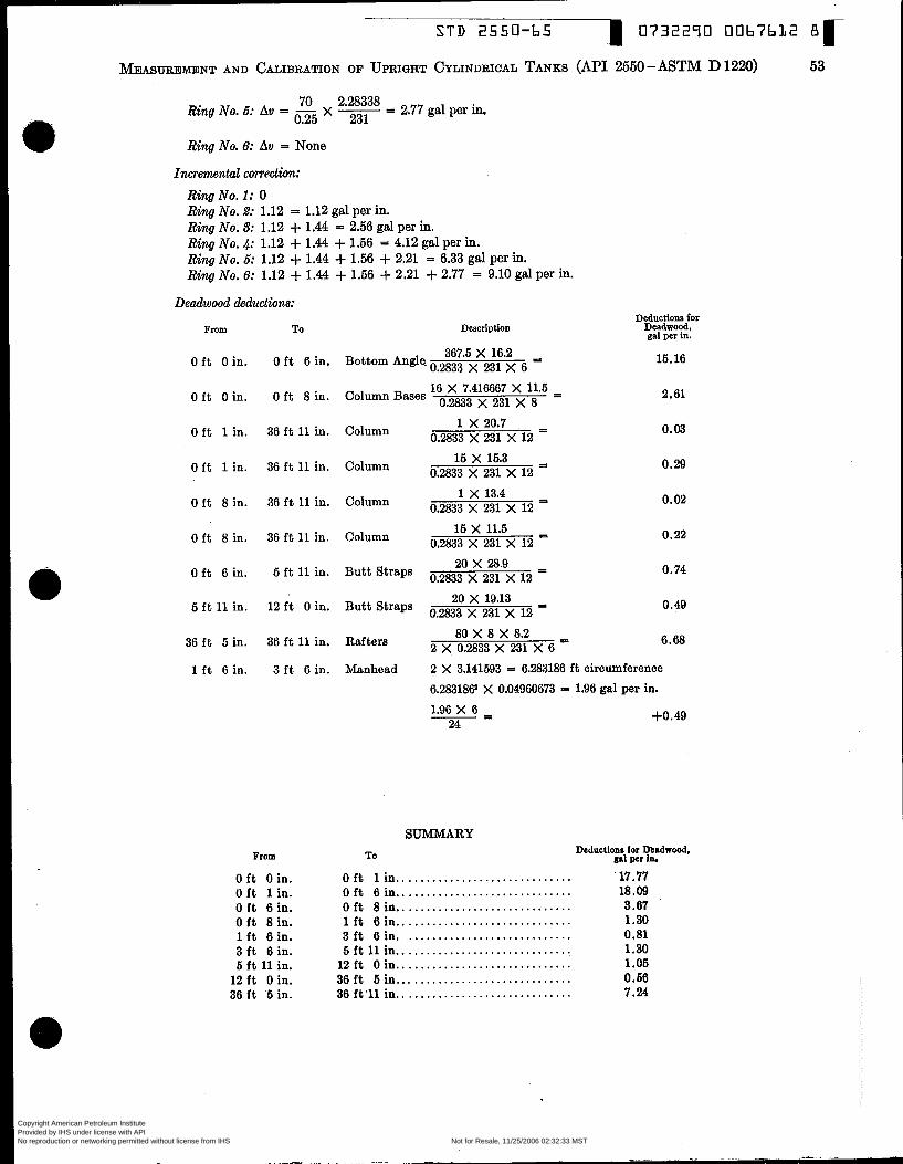
S T D 2550-65 I 0732290 0067612 BK MEASUREME~NT AND CALIBRATION OF UPRIGHT CYLINDRICAL TANKS (MI 2550 - ASTM D 1220) 53
70 2.28338 Ring No. 6: Av = - X - = 2.77 gal per in. 0.25 231
Ring No. 6: Av = None
Incremental Unrectùm:
Ring No. 1: O Ring No. 2: 1.12 = 1.12 gal per in. Ring No. 8: 1.12 + 1.44 = 2.56 gal per in. Ring No. 4: 1.12 + 1.44 + 1.56 = 4.12 gal per in. Ring No. 6: 1.12 + 1.44 + 1.56 + 2.21 = 6.33 gal per in. Ring No. 6: 1.12 + 1.44 + 1.56 + 2.21 + 2.77 = 9.10 gal per in.
Deadwood deductions:
From T O Description
367.5 X 16.2 O f t O in. O f t 6 in. Bottom Angle. o.2833 231
16 X 7.416667 X 11.5 - - 0.2833 X 231 X 8 O f t O in. O f t 8 in. Column Bases
1 X 20.7 I
O f t 1 in. 36 ft 11 in. Column o.2833 231 12
15 X 15.3 - O ft 1 in. 36 ft 11 in. Column o,2833 231 12 - 1 X 13.4 =
O f t 8 in. 36 f t 11 in. Column o.2833 231 12
15 X 11.5 - 0.2833 X 231 X 12 - O f t 8 in. 36 f t 11 in. Column
20 x 28.9 - O f t 6 in. 5 f t 11 in. Butt Straps o.2833 12 - 20 X 19.13 I 5 ft 11 in. 12 f t O in. Butt Straps o.2833 231 12
80 X 8 X 8.2 - 2 X 0.2833 X 231 X 6 - 36 f t 5 in. 36 f t 11 in. Rafters
Deductions for Deadwood, gal per in.
15.16
2.61
0.03
0.29
0.02
0.22
0.74
0.49
6.68
1 f t 6 in. 3 f t 6 in. Manhead 2 X 3.141593 = 6.283186 f t circumference 6.283186 X 0.04960673 = 1.96 gal per in. 1.96 X 6
24 +0.49 -=
From
O f t O in. O ft 1 in. O ft 6 in. O f t 8 in. 1 f t 6 in. 3 f t 6 in. 5 f t 11 in. 12 f t O in. 36 f t 5 in.
SUMMARY DeducUoni for Deadwood.
To gal per In. O f t lin .............................. 17.77 O ft 6 in.. ............................ 18.09 . O f t 8 in.. ............................ 3.67 1 ft 6 in.. ............................ 1.30 3 ft 6 in. ............................ 0.81 5 ft 11 in.. ............................. 1.30 12 f t O in.. ............................ 1 .O5 36 ft 5 in.. ............................ 0.56 36 ft’ll in.. ............................ 7.24
Copyright American Petroleum Institute Provided by IHS under license with API Licensee=Aramco HQ/9980755100
Not for Resale, 11/25/2006 02:32:33 MSTNo reproduction or networking permitted without license from IHS
--`,,,`,,,```,,```,``,`,,,`,`,`-`-`,,`,,`,`,,`---
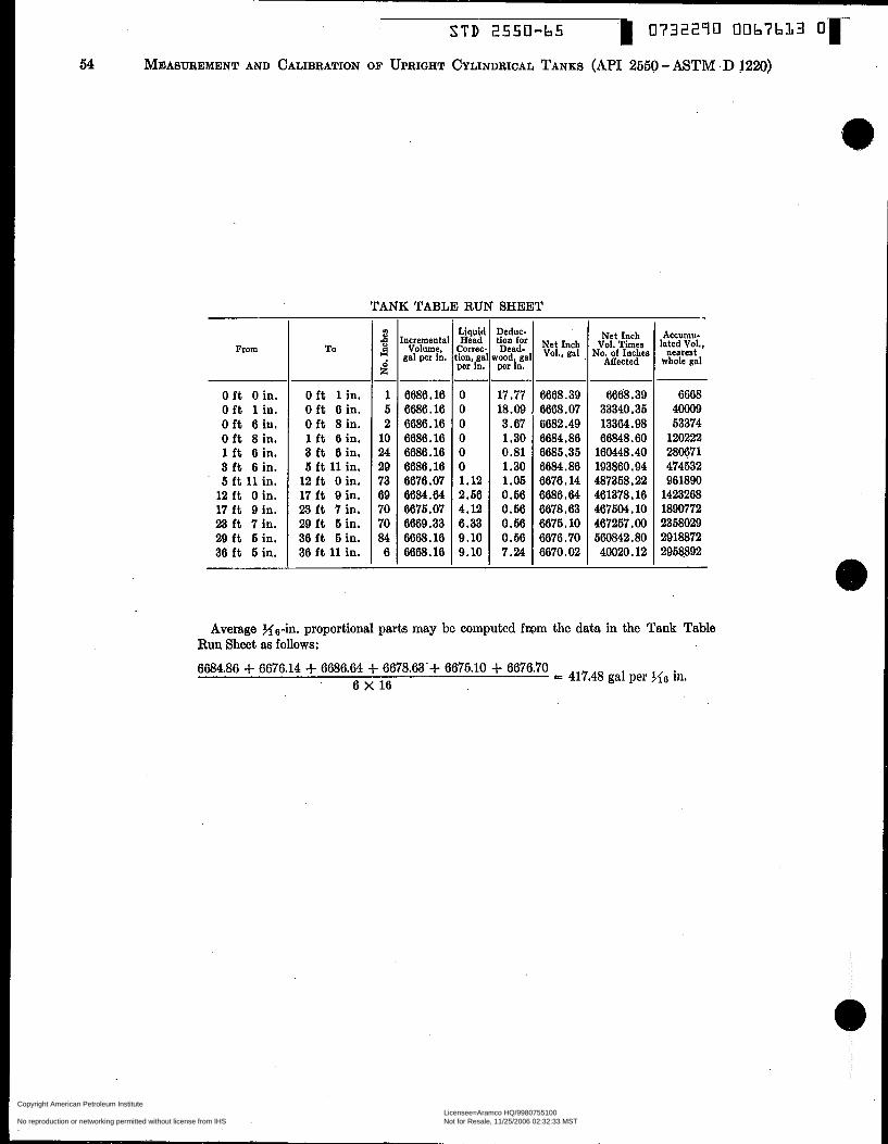
TANK TABLE RUN SHEET
From
O ft O in. O ft 1 in. O ft 6 in. O ft 8 in. 1 ft 6 in. 3 ft 6 in. 5 ft 11 in. 12 ft O in. 17 ft 9 in. 23 ft 7 in. 29 ft 5 in. 36 ft 5 in.
To
O ft 1 in. O ft 6 in. O ft 8 in. 1 ft 6 in. 3 ft 6 in. 5 ft 11 in. 12 ft O in. 17 ft 9 in. 23 ft 7 in. 29 ft 5 in. 36 ft 5 in. 36 ft 11 in.
- B U
i - 1 5 2 10 24 29 73 69 70 70 84 6 -
rncrernenta Volume
gal per iA.
6686.16 6686.16 6686.16 6686.16 6686.16 6686.16 667%. 07 6684.64 6675. o7 6669.33 6668.16 6668.16
Liquid Head
correc. ion,.ga per in.
O O O O O O 1.12 2.66 4.12 6.33 9.10 9.10
Deduc- tion *Or Net Inch ,"tal vol., gai per in. -~ 17 -77 6668.39 18.09 6668.07 3.67 6682.49 1.30 6684.86 0.81 6685.35 1.30 6684.86 1.05 6676.14 0.56 6686.64 0.66 6678.63 0.66 6675.10 0.66 6676.70 7.24 6670.02
Net Inch Vol. Times
No. of Inches ABected
6668.39 33340.35 13364.98 66848.60 160448.40 193860.94 487358.22 461378.16 467504.10 467257.00 580842.80 40020.12
ACCUIUU- lated Vol.,
nearest whole gal
6668 40009 53374 120222 280671 474532 961890 1423268 1890772 2358029 2918872 2958892
Average X6-b. proportional parts may be computed from the data in the Tank Table Run Sheet as follows:
6684.86 + 6676.14 + 6686.64 + 6678.63.+ 6675.10 + 6676.70 6 X 16
417.48 >.ie in.
Copyright American Petroleum Institute Provided by IHS under license with API Licensee=Aramco HQ/9980755100
Not for Resale, 11/25/2006 02:32:33 MSTNo reproduction or networking permitted without license from IHS
--`,,,`,,,```,,```,``,`,,,`,`,`-`-`,,`,,`,`,,`---

STD 2550-65 0732290 0067614 1 r
MEASUREMENT AND CALIBRATION OF UPRIGHT CYLINDRICAL TANKS (API 2550 -MTM D 1220) 55
TABLE VI1.-FACSIMILE OF A TANK GAGE TABLE WITH VOLUMES RECORDED IN GALLONS CUMULATED HORIZONTALLY.
5s,oaO TANK (CO= 8001)-10. IO1
mit ~tiiion - s. n. ca. llh'd" D- X 3oc4-r/L" IMIB. T & b Ilo. i03
i mm I I 1 2 I 3 1 h
Copyright American Petroleum Institute Provided by IHS under license with API Licensee=Aramco HQ/9980755100
Not for Resale, 11/25/2006 02:32:33 MSTNo reproduction or networking permitted without license from IHS
--`,,,`,,,```,,```,``,`,,,`,`,`-`-`,,`,,`,`,,`---

56
0732290 0067635 3 I S T D 2550-65
MEASUREMENT AND CALIBRATION OF UPRIGHT CYLINDRICAL TANKS (API 2550 - ASTM D 1220)
TABLE VII1.-FACSIMILE OF A TANK GAGE TABLE WITH VOLUMES RECORDED IN GALLONS CUMULATED VERTICALLY.
TANK NO..-
Copyright American Petroleum Institute Provided by IHS under license with API Licensee=Aramco HQ/9980755100
Not for Resale, 11/25/2006 02:32:33 MSTNo reproduction or networking permitted without license from IHS
--`,,,`,,,```,,```,``,`,,,`,`,`-`-`,,`,,`,`,,`---
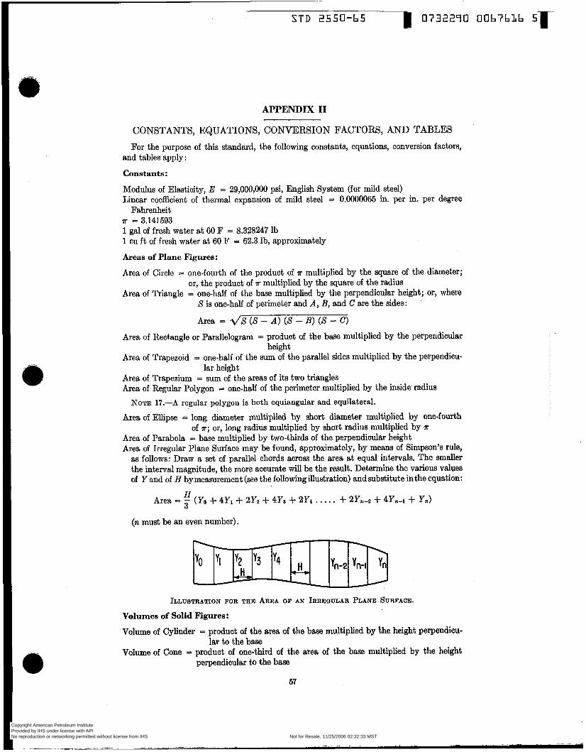
APPENDIX II
CONSTANTS, EQUATIONS, CONVERSION FACTORS, AND TABLES For the purpose of this standard, the following constants, equations, conversion factors,
and tables apply :
Constants :
Modulus of Elmticity, E = 29,000,000 psi, English System (for mild steel) Linear coefficient of thermal expansion of mild steel = 0.0000065 in. per in. per degree
Fahrenheit IF = 3.141593 1 gal of frcsh water a t 60 F = 8.328247 lb 1 CU f t of fresh water a t 60 F = 62.3 lb, approximately
Areas of Plane Figures:
Area of Circle = one-fourth of the product of a multiplied by the square of the diameter;
Area of Triangle = one-half of the base multiplied by the perpendicular height; or, where or, the product of a multiplied by the square of the radius
S is one-half of perimeter and A, B, and C are the sides:
Area = 4 8 (S - A ) (S - B) (S - C) Area of Rectangle or Parallelogram = product of the base multiplied by the perpendicular
Area of Trapezoid I one-half of the sum of the parallel sides multiplied by the perpendicu-
Area of Trapezium = sum of the areas of its two triangles Area of Regular Polygon = one-half of the perimeter multiplied by the inside radius
height
lar height
NOTE 17.-A regular polygon is both equiangular and equilateral.
Area of Ellipse = long diameter multiplied by short diameter multiplied by one-fourth
Area of Parabola = base multiplied by two-thirds of the perpendicular height Area of Irregular Plane Surface may be found, approximately, by means of Simpson’s rule, as follows: Draw a set of parallel chords acroes the area at equal intervals. The smaller the interval magnitude, the more accurate will be the result. Determine the various valves of Y and of H by measurement (see the following illustration) andsubstitute inthe equation:
of n; or, long radius multiplied by short radius multiplied by n
H 3
(n must be an even number).
Area = - (YO + 4Yi + 2Yz + 4Ys + 2Y4 . . . . . + 2Yn-2 + 4Yn-i + Y,)
ILLUSTRATION FOR THE AREA OF AN IRREQULAR PLANE SURFACE.
Volumes of Solid Figures:
Volume of Cylinder = product of the area of the base multiplied by the height perpendicu-
Volume of Cone = product of one-third of the area of the base multiplied by the height lar to the base
perpendicular to the base
67
Copyright American Petroleum Institute Provided by IHS under license with API Licensee=Aramco HQ/9980755100
Not for Resale, 11/25/2006 02:32:33 MSTNo reproduction or networking permitted without license from IHS
--`,,,`,,,```,,```,``,`,,,`,`,`-`-`,,`,,`,`,,`---

STD 2550-65 I 0732270 0067637 7r 68 MEIAS~EMENT AND CALIBRATION OF UPRIGHT CYLINDRICAL TANKS (API 2550-ASTM D 1220)
Volume of Frustum of a Cone = product of one-third of the height perpendicular to the bases multiplied by the sum of the combined areas of the two bases plus the square root of the product of the areas of the two basea
Volume of Sphere = product of four-thirds r multiplied by the cube of the radius; or, one-
volume of Spherical Segment of Only One Base = product of one-sixth ÍT multiplied by the height of the segment, multiplied by the sum of three times the square of the radius of the base of the segment, plus the square of the height of the seg- ment, or:
Volume = - H (3r2 + I l 2 ) 6
where: H = height of segment.
sixth ?r multiplied by the cube of the diameter
?r
T = radius of base. Volume of Spherical Segment of Two Bases = product of the height perpendicular to the
bases multiplied by one-half of the sum of the areas of the two bases, plus the volume of a sphere with diameter equal to the per- pendicular height of the segment, or:
H 7r Volume = - (m12 + m2) + - H3 2 6
?r = - H(3rt + 3r2 + H 2 ) 6
where: H = height of segment. r1 and rp = radii of two bases with both rl
and r2 in the same hemisphere.
Convenient Conversion Factors:
Centigrade Degrees = 54 Fahrenheit Degrees - 32 Fahrenheit Degrees = N Centigrade Degrees + 32 One Barrel = 42 U.S. Gallons U.S. Gallons x 231 = Cubic Inches Cubic Inches x 0.004329004 = US. Gallons Cubic Feet x 7.480519 = US. Gallons Circumference x 0.3183098 = Diameter Diameter x 3.141593 = Circumference
Copyright American Petroleum Institute Provided by IHS under license with API Licensee=Aramco HQ/9980755100
Not for Resale, 11/25/2006 02:32:33 MSTNo reproduction or networking permitted without license from IHS
--`,,,`,,,```,,```,``,`,,,`,`,`-`-`,,`,,`,`,,`---

TABLE IX.-WEIGHTS OF STEEL SHEETS AND PLATES. U . S . STANDARD GAGE .
Gape No . ____-
3. ........ 4 ......... 5 ......... 6 . . . . . . . . . 7 ......... 8 ......... 9 . . . . . . . . .
10 ......... 11 ......... 12 ......... 13 ......... 14 ......... 15 ......... 16 ......... 17 ......... 18 ......... 19 ......... 20 ......... 21 ......... 22 ......... 23 ......... 24 .........
25 ......... 20 ......... 27 ......... 28 ......... 29 .........
30 ......... 31 ......... 32 ......... 33 ......... 34 .........
35 ......... 36 ......... 37 ......... 38 .........
Weight
oz per sq ft
160 150
140 130 120 110 100
90 80 70 60 50
45 40 30 32 28
24 22 20 18 10
14 12 11 10 9
8 7 6.5 6 5.5
5 4.5 4.25 4
.
S T D 2550-65 0 7 3 ~ ~ ~ 0 0067618 q- MEASURENENT AND CALIBRATION OF UPRIGHT CYLINDRICAL TANKS ( M I 2550 . U T M D 1220) 59
... .... ~ ~ . _ - .... - - ~-
Ib per sq ft
10.00 9.38
8.75 8.12 7.50 6.88 6.25
5.62 5.00 4.38 3.75 3.12
2.81 2.50 2.25 2.00 1.75
1.50 1.38 1.25 1.12 1 . 00
0.876 0.750 0.688 0.025 0.562
0.500 0.438 0.406 O . 375 0.344
O . 312 0.281 O . 266 0.250
~ppraxima~c Thickness. 111 .
0.2391 0 . 2242
0.2092 0.1943 0 . 1793 0 . 1644 0 . 1495
0 . 1345 0.1196 0.1046 0 . 0897 0 . 0747
0 . 0673 0 . 0598 0.0538 0.0478 0 . 0418
0 . 0359 0 . 0329 0 . 0299 0 . 0269 0 * 0239
0.0209 0.0179 0 . 0164 0.0149 0.0135
0.0120 0 . 0105 0.0097 O.OO90 0 . 0082
0 . 0075 0.0067 0.0064 O.Oo60
Copyright American Petroleum Institute Provided by IHS under license with API Licensee=Aramco HQ/9980755100
Not for Resale, 11/25/2006 02:32:33 MSTNo reproduction or networking permitted without license from IHS
--`,,,`,,,```,,```,``,`,,,`,`,`-`-`,,`,,`,`,,`---
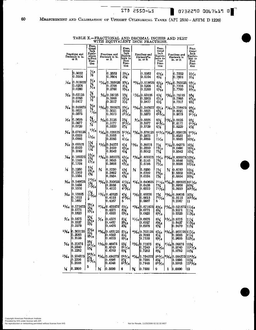
S T D 2550-6C 0732290 0067639 O r
Frac- tional
ents to Foot Frac- tion
60 MEASUREMENT AND CALIBRATION OF UPRIGHT CYLINDRICAL TANKS (API 2550-ASTM D 1220)
Frac. tional
in. orft l?Jo0:(> Frac- tion
Fractions and Dtcimals in
TABLE X.-FRACTIONAL AND DECIMAL INCHES AND FEET WITH EQUIVALENT INCH FRACTIONS.
1x1
1x4
x6
2 ? 4 4
'%2
2944
8944
LM2
"4 .
q 6
IN4
..$a
?44
.ri
Fractions and Decimals in in
or ft
O. 2552 0.2604 0.26562 O. 2708 0.2760 0.28125 O. 2865 O. 2917 O. 29687, O .3021 O. 3073
0.3177 0.3229
0.3333 0.3385 o. 34375 O. 3490 O, 3542 o. 359371 O. 3646 O. 3698 0.3760 0.3802 0.3854
O. 3958 O. 4010 O. 40625 0.4115 O. 4167
0.4271 O. 4323
0.4427 0.4479 O. 453121 0.4583 0.4635 O. 46875 0.4740 O , 4792 O. 484375 0.4896 O. 4948 0 . m
0.3125
O. 328121
O. 3W6Z
O. 421871
0.4375
Io.w52 0.0104
3944
1 x 2
8944
?'$6
3x4
Na
3x4
N
+%4
2 % ~
4944
'HG
&%4
1 % ~
i%4
y
?44 0.0156: O. 0208 o. 0260
O . 5052 O . 5104 O. 51562, O. 5208 O. 5260 0.53125 O. 5365 O. 5417 O. 54687! O. 5521 O. 5573
O. 5677 O. 5729 O. 57812! 0.5833 0.5885 0.59375 O. 5990 O. 6042 o .60937! 0.6146 O. 6198 0.6250 O. 6302 O. 6354 o. 640621 O, 6458 O. 6510
0.6615 O. 6667 O. 67187: 0.6771 O. 6823
O. 6927 O. 6979 0.703125 O. 7083 0.7135 0.71875 0.7240 O. 7292 o .734375 O .7396 O. 7448 0.7500
0.5625
O . 65625
O a 6875
Ha 0.03121 O. 0365 0.0417
944 0.0468; O. 0521 0.0573 0.0625 O. 0677 O. 0729
%.r 0.0781: 10.088 0.0833
?& 0.09371 0.0990 O, 1042
x4 0.10937 0.1146 O . 1198
tg 0.1250
Ns 0.14062
O. 1302 O, 1354
O. 1458 O. 1510 0.15625 0.1615 O. 1667
1?44 0.17187 O. 1771 O. 1823 0.1875 o. 1927 O. 1979
0.2135
o. 2240
'944 0,23437, O. 2396 0.2448
?4 0.2500
- Frac tiona
Equi alent toFoc Frac tion
In+
- Frac- tional Inch
Equiva lents ti
Foot Frac- tion -
@ 3% 3% 3% 3% 3% 3% 3x6 3% 3% 3% 31% 3%
4x6 4% 4% 4?4 4x6 4% 4x6 4% 4% 4% 41xa 4% 4% 4%
41%
51x6
5p
:p 5% 5%
5% 5% 5?46
5% 51946 5% 51% 6
Copyright American Petroleum Institute Provided by IHS under license with API Licensee=Aramco HQ/9980755100
Not for Resale, 11/25/2006 02:32:33 MSTNo reproduction or networking permitted without license from IHS
--`,,,`,,,```,,```,``,`,,,`,`,`-`-`,,`,,`,`,,`---
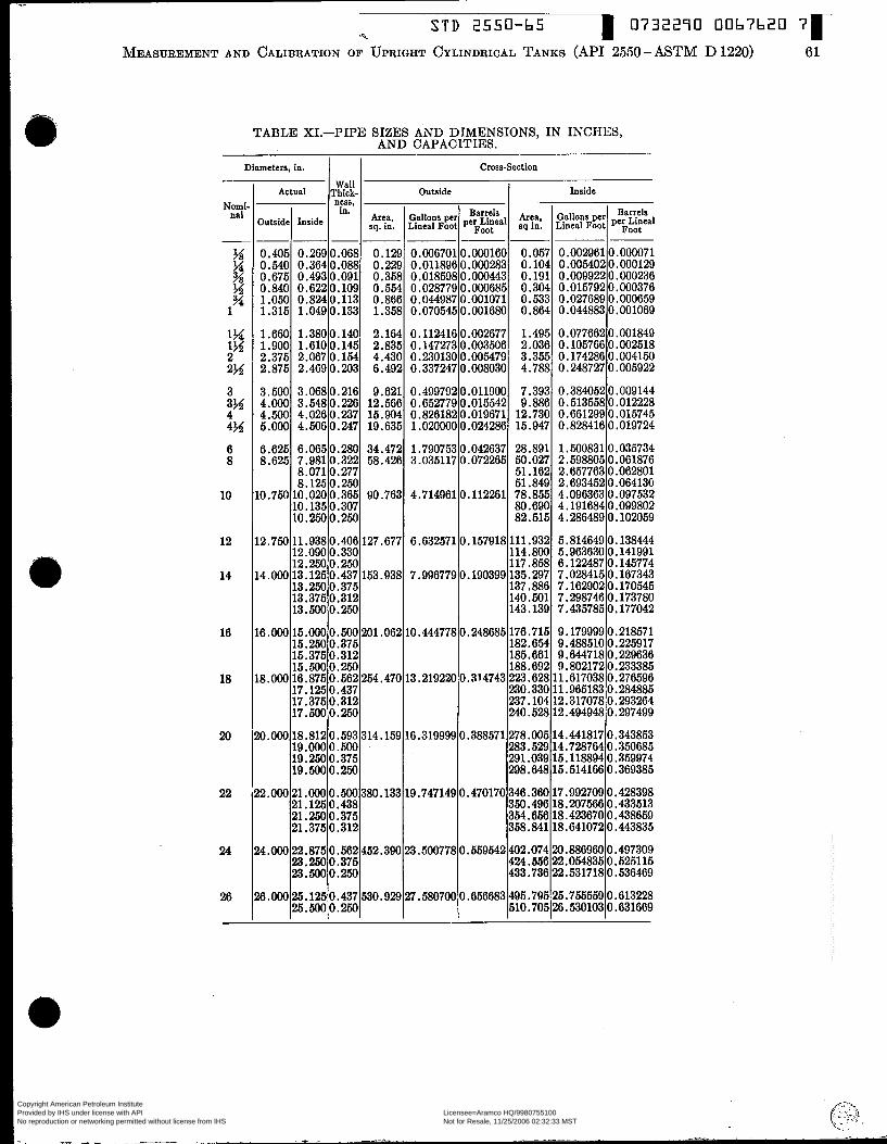
S T D 2550-b5 0732290 OOb7620 7r MEASUREMENT AND CALIBRATION OF UPRIGHT CYLINDRICAL TANKS (API 2550 - ASTM D 1220) 61
0.405 0.540 0.675 0.840 1.050 1.315
TABLE XI.-PIPE SIZES AND DIMENSIONS, IN INCHES, AND CAPACITIES.
- - - - ~ ~ 0.2690.068 0.129 0.006701 O.OOO160 0.3640.088 0.229 0.0118960.000283 0.4930.091 0.358 0.0185980.000443 0.6220.109 0.554 0.0287790.000685 0.8240.113 0.866 0.044987 0.001071 1 .O49 O . 133 1.358 O .O70545 0.001680
Diameten,in. I I Cross-Section
0.057 0.104 O. 191 0.304 O . 533 0.864
-
Nomi- nal
- %
M %
1% 1%
2%
# 1
2
3
4% Y 6 8
10
12
14
16
18
20
22
24
26
-
0.002961 0.000071 0.0054020.000129 O .O09922 O .O00236 0.015792 0.000376 O .O27689 O . O00659 0.044883 O.OO1069
I Actual IT:$!- 1 Outside ness.
1.660 1.900 2.375 2.875
3.500 4.000 4.500 5.000
1.380 O . 140 2.164 O . 112416 O .O02677 1.495 0.077662 O .O01819 1.6100.145 2.835 0.1472730.003506 2.036 0.1057660.002518 2.0670.154 4.430 0.2301300.005479 3.355 0.1742860.004150 2.469 0.203 6.492 0.337247 0.008030 4.788 0.24878 0.005922
3.0680.216 9.621 0.4997920.011900 7.393 0.3840520.009144 3.5480.226 12.566 0.652779 0.015542 9.686 0.513558 0.012228 4.0260.237 15.904 0.8261820.019671 12.730 0.6612990.015745 4.5060.247 19.635 1.0200000.024286 15.947 0.8284160.019724
inside
6.625 8.625
r0.750
Area, Gallons per sq in. I I Lineal Foot P C ~ ~ ~ M 1
6.0650.280 7.981 0.322 8.071 0.277 8.1250.250
10.0200.365 10.135 0.307 10.2500.250
.790753 8.035117
O. 042637 0.072265
.7149610.112261
.._. ~
2.598805 2.657763 2.693452 4 .O96363
34.472 58.426
90.763
0.061876 O .O62801 0.06413G O .O97532
8.632571
.996779
28.891 50.027 51.162 51.849 78.855 80.690 82.515
O
O
.157918
.190399
111.932 114.800 117.858 135.297 137,886 140.601 143.139
1. M083110.035734
.6.ooO
.8.OOO
15.0000.500 201.062 10.444778 0.248685 176.715 9.179999 0.218571 15.2500.375 182.654 9.488510 0.225917 15.375 0.312 185.661 9.644718 0.229636 15.5000.250 188.692 9.802172 0.233385 16.875 0.562 254.470 13.219220 0.314743 223.628 11.617038 0.276596 17.125 0.437 230.330 11.965183 O. 284885 17.375 O. 312 237.104 12.317078 0.2!33264 17.5000.250 240.528 12.494948 O. 297499
4.191684 4.28648910.102059 O .O99802
!O.ooO
0.ooO
7.298746 O. 173780 7.435785 O. 177042
18.812 0.593 314.159 16.319999 0.388571 278.005 14.441817 0.343853 19.0000.500 283.529 14.728764 0.350685 19.260 O .375 291.039 15.118894 0.359974 19.500 0.250 298.648 15.514166 0.369385
21.000 0.500 380.133 19.747149 0.470170 346.360 17.992709 0.428398 21.125 0.438 350.496 18.207566 O. 433513 21.250 0.375 351.656 18.423670 O. 438659 21.375 O .312 358.841 18.6410720.443835
M.ooO 22.8750.562452.390 23.5007780.559542402.074 20.8869600.497309 I~:%$:%!I 1 I 1433.73122.8171~0.636169 424.656 22 -054835 O. 5251 15
!$.O00 25.1250.437 530.929 27.580700 0.656683 195.795125.755559 0.613228 126.6oo~o.m~ I 1 ~5io.705~26.530103~0.631669
Copyright American Petroleum Institute Provided by IHS under license with API Licensee=Aramco HQ/9980755100
Not for Resale, 11/25/2006 02:32:33 MSTNo reproduction or networking permitted without license from IHS
--`,,,`,,,```,,```,``,`,,,`,`,`-`-`,,`,,`,`,,`---