APEM DIP & Rotary DIP Switches - Digi-Key Sheets/APEM Components PDFs/D… · specifications...
24
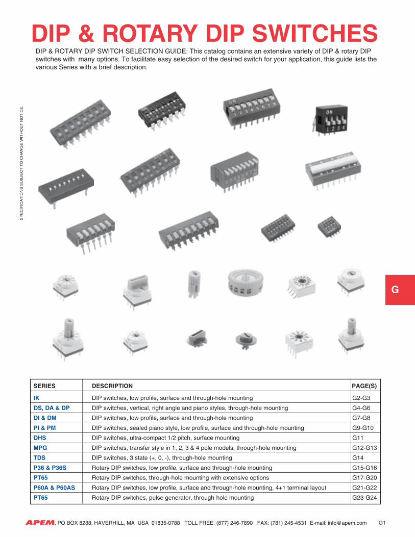
SPECIFICATIONS SUBJECT TO CHANGE WITHOUT NOTICE. G APEM, PO BOX 8288, HAVERHILL, MA USA 01835-0788 TOLL FREE: (877) 246-7890 FAX: (781) 245-4531 E-mail: [email protected] G1 SERIES DESCRIPTION PAGE(S) IK DIP switches, low profile, surface and through-hole mounting G2-G3 DS, DA & DP DIP switches, vertical, right angle and piano styles, through-hole mounting G4-G6 DI & DM DIP switches, low profile, surface and through-hole mounting G7-G8 PI & PM DIP switches, sealed piano style, low profile, surface and through-hole mounting G9-G10 DHS DIP switches, ultra-compact 1/2 pitch, surface mounting G11 MPG DIP switches, transfer style in 1, 2, 3 & 4 pole models, through-hole mounting G12-G13 TDS DIP switches, 3 state (+, 0, -), through-hole mounting G14 P36 & P36S Rotary DIP switches, low profile, surface and through-hole mounting G15-G16 PT65 Rotary DIP switches, through-hole mounting with extensive options G17-G20 P60A & P60AS Rotary DIP switches, low profile, surface and through-hole mounting, 4+1 terminal layout G21-G22 PT65 Rotary DIP switches, pulse generator, through-hole mounting G23-G24 DIP & ROTARY DIP SWITCHES DIP & ROTARY DIP SWITCH SELECTION GUIDE: This catalog contains an extensive variety of DIP & rotary DIP switches with many options. To facilitate easy selection of the desired switch for your application, this guide lists the various Series with a brief description.
Transcript of APEM DIP & Rotary DIP Switches - Digi-Key Sheets/APEM Components PDFs/D… · specifications...
SP
EC
IFIC
AT
ION
S S
UB
JEC
T T
O C
HA
NG
E W
ITH
OU
T N
OT
ICE
.
G
APEM, PO BOX 8288, HAVERHILL, MA USA 01835-0788 TOLL FREE: (877) 246-7890 FAX: (781) 245-4531 E-mail: [email protected] G1
SERIES DESCRIPTION PAGE(S)
IK DIP switches, low profile, surface and through-hole mounting G2-G3
DS, DA & DP DIP switches, vertical, right angle and piano styles, through-hole mounting G4-G6
DI & DM DIP switches, low profile, surface and through-hole mounting G7-G8
PI & PM DIP switches, sealed piano style, low profile, surface and through-hole mounting G9-G10
DHS DIP switches, ultra-compact 1/2 pitch, surface mounting G11
MPG DIP switches, transfer style in 1, 2, 3 & 4 pole models, through-hole mounting G12-G13
TDS DIP switches, 3 state (+, 0, -), through-hole mounting G14
P36 & P36S Rotary DIP switches, low profile, surface and through-hole mounting G15-G16
PT65 Rotary DIP switches, through-hole mounting with extensive options G17-G20
P60A & P60AS Rotary DIP switches, low profile, surface and through-hole mounting, 4+1 terminal layout G21-G22
PT65 Rotary DIP switches, pulse generator, through-hole mounting G23-G24
DIP & ROTARY DIP SWITCHES DIP & ROTARY DIP SWITCH SELECTION GUIDE: This catalog contains an extensive variety of DIP & rotary DIP switches with many options. To facilitate easy selection of the desired switch for your application, this guide lists the various Series with a brief description.
SP
EC
IFIC
AT
ION
S S
UB
JEC
T T
O C
HA
NG
E W
ITH
OU
T N
OT
ICE
.
G
APEM, PO BOX 8288, HAVERHILL, MA USA 01835-0788 TOLL FREE: (877) 246-7890 FAX: (781) 245-4531 E-mail: [email protected]
GENERAL SPECIFICATIONS
ELECTRICALS
Electrical life 2000 cycles minimumContact rating, non-switching 100 mA at 48 VDCContact rating, switching 100 mA at 24 VDCInitial contact resistance 30 mΩ maximum
after 2000 cycles: 100 mΩ max.Insulation resistance 1000 MΩ min. at 500 VDCDielectric strength 500 VAC minimum
MECHANICALS, THERMALSTravel .026" (0.67mm)Operating temperature range -40°C to +100°CStorage temperature range -40°C to +125°C
SOLDERING & CLEANING RECOMMENDATIONSHand soldering 330°C max. for 3 seconds max.(30 watt iron max.)Reflow soldering Set oven at 215°C max. for 90 seconds max.Cleaning 1-1-1 Trichloroethane, Freon TE, Isopropyl alcohol or aqueous(with standard tape seal) cleaner for 2 minutes max. at 20°C
MATERIALS
Case UL94-VO, thermoplastic, whiteActuators UL94-VO, thermoplastic, blackStationary contact Gold over nickel over bronzeMoving contact Gold over beryllium copperTerminals Tin plated over nickel barrier
Tape seal Polyimide
ANTISTATIC PACKAGINGStandard packaging:Reels of 1,000 units - Tape meeting IEC Standard - Pub-lication 286-3 (EIA481A). Start leader: 15.7" (400mm) min.End leader: 6.3" (160mm) - see illustration.IC tubes - see illustration
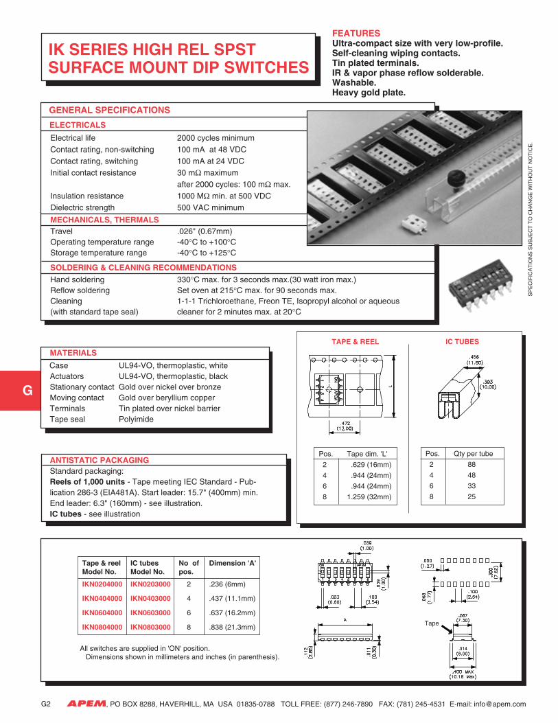
IK SERIES HIGH REL SPST SURFACE MOUNT DIP SWITCHES
FEATURESUltra-compact size with very low-profile.Self-cleaning wiping contacts.Tin plated terminals.IR & vapor phase reflow solderable.Washable.Heavy gold plate.
Tape & reel IC tubes No of Dimension 'A'Model No. Model No. pos.
IKN0204000 IKN0203000 2 .236 (6mm)
IKN0404000 IKN0403000 4 .437 (11.1mm)
IKN0604000 IKN0603000 6 .637 (16.2mm)
IKN0804000 IKN0803000 8 .838 (21.3mm)
All switches are supplied in 'ON' position. Dimensions shown in millimeters and inches (in parenthesis).
Pos. Tape dim. 'L'
2 .629 (16mm)
4 .944 (24mm)
6 .944 (24mm)
8 1.259 (32mm)
Pos. Qty per tube
2 88
4 48
6 33
8 25
TAPE & REEL IC TUBES
G2
Tape
SP
EC
IFIC
AT
ION
S S
UB
JEC
T T
O C
HA
NG
E W
ITH
OU
T N
OT
ICE
.
G
APEM, PO BOX 8288, HAVERHILL, MA USA 01835-0788 TOLL FREE: (877) 246-7890 FAX: (781) 245-4531 E-mail: [email protected]
GENERAL SPECIFICATIONS
ELECTRICALS
Electrical life 2000 cycles minimumContact rating, non-switching 100 mA at 48 VDC
Contact rating, switching 100 mA at 24 VDCInitial contact resistance 30 mΩ maximum
after 2000 cycles: 100 mΩ max.Insulation resistance 1000 MΩ min. at 500 VDCDielectric strength 500 VAC minimum
MECHANICALS, THERMALSTravel .026" (0.67mm)Operating temperature range -40°C to +100°CStorage temperature range -40°C to +125°C
SOLDERING & CLEANING RECOMMENDATIONSHand soldering 330°C max. for 3 seconds max.(30 watt iron max.)Reflow soldering Set oven at 215°C max. for 90 seconds max.Cleaning 1-1-1 Trichloroethane, Freon TE, Isopropyl alcohol or aqueous(with standard tape seal) cleaner for 2 minutes max. at 20°C
MATERIALS
Case UL94-VO, thermoplastic, whiteActuators UL94-VO, thermoplastic, blackStationary contact Gold over nickel over bronzeMoving contact Gold over beryllium copperTerminals Tin plated over nickel barrier
Tape seal Polyimide
ANTISTATIC PACKAGING
Standard packaging:IC tubes - see illustration
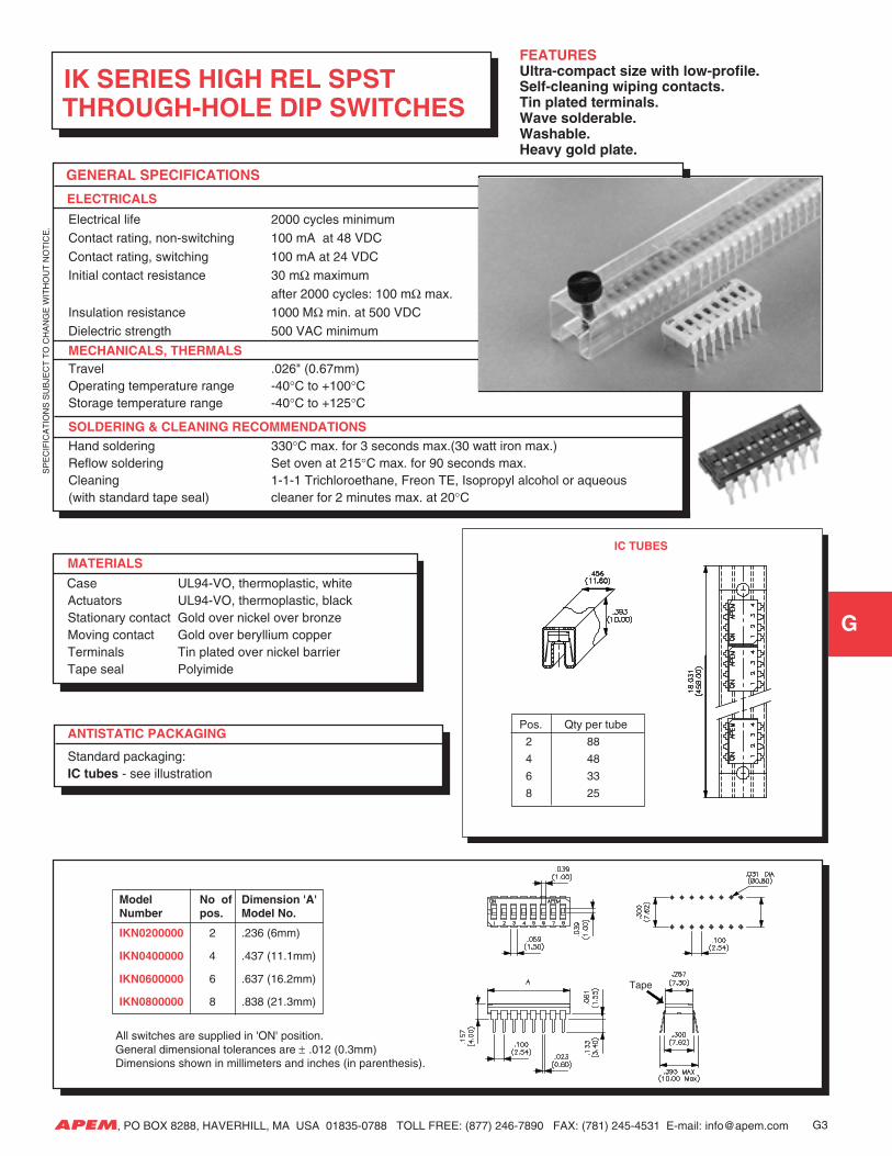
IK SERIES HIGH REL SPST THROUGH-HOLE DIP SWITCHES
FEATURESUltra-compact size with low-profile.Self-cleaning wiping contacts.Tin plated terminals.Wave solderable.Washable.Heavy gold plate.
Model No of Dimension 'A'Number pos. Model No.
IKN0200000 2 .236 (6mm)
IKN0400000 4 .437 (11.1mm)
IKN0600000 6 .637 (16.2mm)
IKN0800000 8 .838 (21.3mm)
All switches are supplied in 'ON' position. General dimensional tolerances are ± .012 (0.3mm) Dimensions shown in millimeters and inches (in parenthesis).
Pos. Qty per tube
2 88
4 48
6 33
8 25
IC TUBES
G3
Tape
SP
EC
IFIC
AT
ION
S S
UB
JEC
T T
O C
HA
NG
E W
ITH
OU
T N
OT
ICE
.
G
APEM, PO BOX 8288, HAVERHILL, MA USA 01835-0788 TOLL FREE: (877) 246-7890 FAX: (781) 245-4531 E-mail: [email protected]
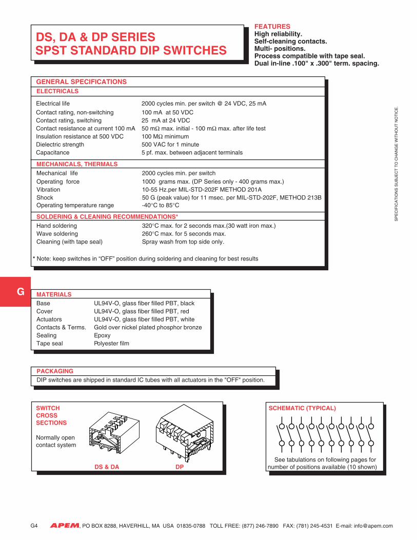
DS, DA & DP SERIES SPST STANDARD DIP SWITCHES
FEATURESHigh reliability.Self-cleaning contacts.Multi- positions.Process compatible with tape seal.Dual in-line .100" x .300" term. spacing.
GENERAL SPECIFICATIONS ELECTRICALS
Electrical life 2000 cycles min. per switch @ 24 VDC, 25 mA
Contact rating, non-switching 100 mA at 50 VDCContact rating, switching 25 mA at 24 VDCContact resistance at current 100 mA 50 mΩ max. initial - 100 mΩ max. after life testInsulation resistance at 500 VDC 100 MΩ minimumDielectric strength 500 VAC for 1 minuteCapacitance 5 pf. max. between adjacent terminals
MECHANICALS, THERMALSMechanical life 2000 cycles min. per switchOperating force 1000 grams max. (DP Series only - 400 grams max.)Vibration 10-55 Hz.per MIL-STD-202F METHOD 201AShock 50 G (peak value) for 11 msec. per MIL-STD-202F, METHOD 213BOperating temperature range -40°C to 85°C
SOLDERING & CLEANING RECOMMENDATIONS*Hand soldering 320°C max. for 2 seconds max.(30 watt iron max.)Wave soldering 260°C max. for 5 seconds max.Cleaning (with tape seal) Spray wash from top side only.
* Note: keep switches in “OFF” position during soldering and cleaning for best results
MATERIALSBase UL94V-O, glass fiber filled PBT, blackCover UL94V-O, glass fiber filled PBT, redActuators UL94V-O, glass fiber filled PBT, whiteContacts & Terms. Gold over nickel plated phosphor bronzeSealing EpoxyTape seal Polyester film
PACKAGING DIP switches are shipped in standard IC tubes with all actuators in the "OFF" position.
SWITCH SCHEMATIC (TYPICAL) CROSS SECTIONS
Normally open contact system
See tabulations on following pages for DS & DA DP number of positions available (10 shown)
G4
SP
EC
IFIC
AT
ION
S S
UB
JEC
T T
O C
HA
NG
E W
ITH
OU
T N
OT
ICE
.
G
APEM, PO BOX 8288, HAVERHILL, MA USA 01835-0788 TOLL FREE: (877) 246-7890 FAX: (781) 245-4531 E-mail: [email protected]
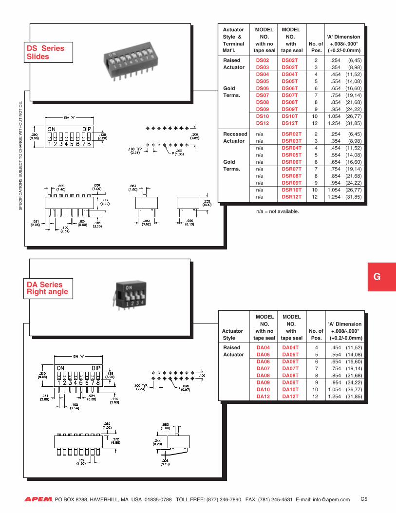
Actuator MODEL MODEL Style & NO. NO. 'A' Dimension Terminal with no with No. of +.008/-.000"
Mat'l. tape seal tape seal Pos. (+0.2/-0.0mm)
Raised DS02 DS02T 2 .254 (6,45)Actuator DS03 DS03T 3 .354 (8,98)
DS04 DS04T 4 .454 (11,52)DS05 DS05T 5 .554 (14,08)
Gold DS06 DS06T 6 .654 (16,60)Terms. DS07 DS07T 7 .754 (19,14)
DS08 DS08T 8 .854 (21,68)DS09 DS09T 9 .954 (24,22)DS10 DS10T 10 1.054 (26,77)DS12 DS12T 12 1.254 (31,85)
Recessed n/a DSR02T 2 .254 (6,45)Actuator n/a DSR03T 3 .354 (8,98)
n/a DSR04T 4 .454 (11,52)n/a DSR05T 5 .554 (14,08)
Gold n/a DSR06T 6 .654 (16,60)Terms. n/a DSR07T 7 .754 (19,14)
n/a DSR08T 8 .854 (21,68)n/a DSR09T 9 .954 (24,22)n/a DSR10T 10 1.054 (26,77)n/a DSR12T 12 1.254 (31,85)
DS SeriesSlides
DA Series Right angle
MODEL MODEL NO. NO. 'A' Dimension
Actuator with no with No. of +.008/-.000" Style tape seal tape seal Pos. (+0.2/-0.0mm)
Raised DA04 DA04T 4 .454 (11,52)Actuator DA05 DA05T 5 .554 (14,08)
DA06 DA06T 6 .654 (16,60)DA07 DA07T 7 .754 (19,14)DA08 DA08T 8 .854 (21,68)DA09 DA09T 9 .954 (24,22)DA10 DA10T 10 1.054 (26,77)DA12 DA12T 12 1.254 (31,85)
G5
n/a = not available.
SP
EC
IFIC
AT
ION
S S
UB
JEC
T T
O C
HA
NG
E W
ITH
OU
T N
OT
ICE
.
G
APEM, PO BOX 8288, HAVERHILL, MA USA 01835-0788 TOLL FREE: (877) 246-7890 FAX: (781) 245-4531 E-mail: [email protected]
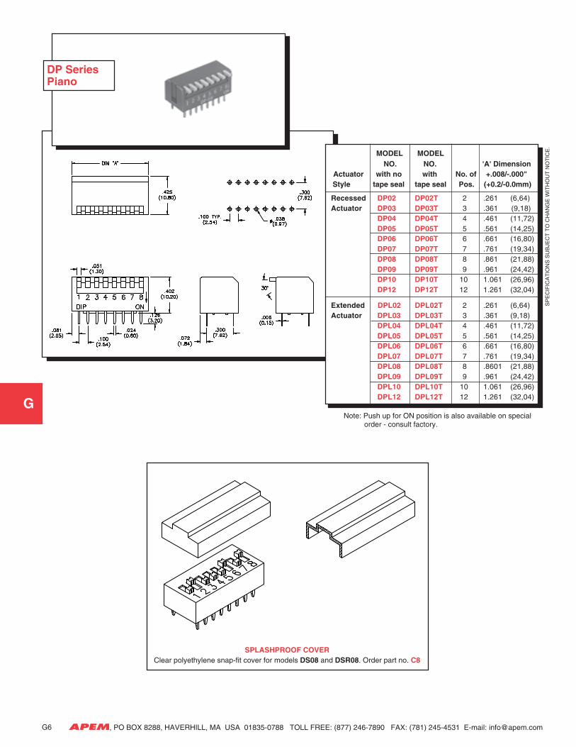
Note: Push up for ON position is also available on special order - consult factory.
MODEL MODEL NO. NO. 'A' Dimension
Actuator with no with No. of +.008/-.000" Style tape seal tape seal Pos. (+0.2/-0.0mm)
Recessed DP02 DP02T 2 .261 (6,64)Actuator DP03 DP03T 3 .361 (9,18)
DP04 DP04T 4 .461 (11,72)DP05 DP05T 5 .561 (14,25)DP06 DP06T 6 .661 (16,80)DP07 DP07T 7 .761 (19,34)DP08 DP08T 8 .861 (21,88)DP09 DP09T 9 .961 (24,42)DP10 DP10T 10 1.061 (26,96)DP12 DP12T 12 1.261 (32,04)
Extended DPL02 DPL02T 2 .261 (6,64)Actuator DPL03 DPL03T 3 .361 (9,18)
DPL04 DPL04T 4 .461 (11,72)DPL05 DPL05T 5 .561 (14,25)DPL06 DPL06T 6 .661 (16,80)DPL07 DPL07T 7 .761 (19,34)DPL08 DPL08T 8 .8601 (21,88)DPL09 DPL09T 9 .961 (24,42)DPL10 DPL10T 10 1.061 (26,96)DPL12 DPL12T 12 1.261 (32,04)
DP SeriesPiano
SPLASHPROOF COVERClear polyethylene snap-fit cover for models DS08 and DSR08. Order part no. C8
G6
SP
EC
IFIC
AT
ION
S S
UB
JEC
T T
O C
HA
NG
E W
ITH
OU
T N
OT
ICE
.
G
APEM, PO BOX 8288, HAVERHILL, MA USA 01835-0788 TOLL FREE: (877) 246-7890 FAX: (781) 245-4531 E-mail: [email protected]
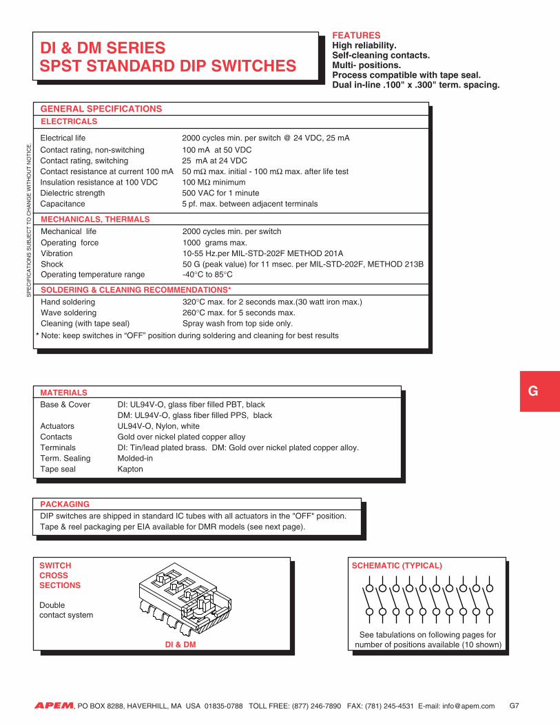
FEATURESHigh reliability.Self-cleaning contacts.Multi- positions.Process compatible with tape seal.Dual in-line .100" x .300" term. spacing.
GENERAL SPECIFICATIONS ELECTRICALS
Electrical life 2000 cycles min. per switch @ 24 VDC, 25 mA
Contact rating, non-switching 100 mA at 50 VDCContact rating, switching 25 mA at 24 VDCContact resistance at current 100 mA 50 mΩ max. initial - 100 mΩ max. after life testInsulation resistance at 100 VDC 100 MΩ minimumDielectric strength 500 VAC for 1 minuteCapacitance 5 pf. max. between adjacent terminals
MECHANICALS, THERMALSMechanical life 2000 cycles min. per switchOperating force 1000 grams max.Vibration 10-55 Hz.per MIL-STD-202F METHOD 201AShock 50 G (peak value) for 11 msec. per MIL-STD-202F, METHOD 213BOperating temperature range -40°C to 85°C
SOLDERING & CLEANING RECOMMENDATIONS*Hand soldering 320°C max. for 2 seconds max.(30 watt iron max.)Wave soldering 260°C max. for 5 seconds max.Cleaning (with tape seal) Spray wash from top side only.
* Note: keep switches in “OFF” position during soldering and cleaning for best results
MATERIALSBase & Cover DI: UL94V-O, glass fiber filled PBT, black
DM: UL94V-O, glass fiber filled PPS, blackActuators UL94V-O, Nylon, whiteContacts Gold over nickel plated copper alloyTerminals DI: Tin/lead plated brass. DM: Gold over nickel plated copper alloy.Term. Sealing Molded-inTape seal Kapton
PACKAGING DIP switches are shipped in standard IC tubes with all actuators in the "OFF" position. Tape & reel packaging per EIA available for DMR models (see next page).
SWITCH SCHEMATIC (TYPICAL) CROSS SECTIONS
Double contact system
See tabulations on following pages for DI & DM number of positions available (10 shown)
DI & DM SERIES SPST STANDARD DIP SWITCHES
G7
SP
EC
IFIC
AT
ION
S S
UB
JEC
T T
O C
HA
NG
E W
ITH
OU
T N
OT
ICE
.
G
APEM, PO BOX 8288, HAVERHILL, MA USA 01835-0788 TOLL FREE: (877) 246-7890 FAX: (781) 245-4531 E-mail: [email protected]
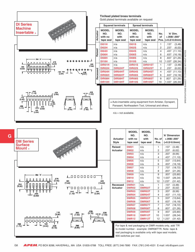
Squared terminals Spread terminals
MODEL MODEL MODEL MODEL NO. NO. NO. NO. No. 'A' Dim. with no with with no with of +.008/-.000"
tape seal tape seal tape seal tape seal Pos. (+0.2/-0.0mm)
DI01H n/a DI01S n/a 1 .137 (3,48)DI02H n/a DI02S n/a 2 .237 (6,02)DI04H n/a DI04S n/a 4 .437 (11.10)DI06H n/a DI06S n/a 6 .637 (16,18)DI08H n/a DI08S n/a 8 .837 (21,26)DI10H n/a DI10S n/a 10 1.037 (26,34)DIR01H n/a DIR01S DIR01ST 1 .137 (3,48)DIR02H DIR02HT DIR02S DIR02ST 2 .237 (6,02)DIR04H DIR04HT DIR04S DIR04ST 4 .437 (11,10)DIR06H DIR06HT DIR06S DIR06ST 6 .637 (16,18)DIR08H DIR08HT DIR08S DIR08ST 8 .837 (21,26)DIR10H DIR10HT DIR10S DIR10ST 10 1.037 (26,34)
Rec
esse
dR
aise
dA
ctu
ato
r
DI SeriesMachineInsertable
n/a = not available.
Auto-insertable using equipment from Amistar, Dynapert,
Panasert, Northeastern Tool, Universal and others.
Tin/lead plated brass terminalsGold plated terminals available on request
G8
DM Series Surface Mount
MODEL MODEL NO. NO. 'A' Dimension
Actuator with no with No. of +.008/-.000" Style tape seal tape seal Pos. (+0.2/-0.0mm)
Raised DM01 n/a 1 .137 (3,48)Actuator DM02 n/a 2 .237 (6,02)
DM03 n/a 3 .337 (8,56)DM04 n/a 4 .437 (11,10)DM05 n/a 5 .537 (13,64)DM06 n/a 6 .637 (16,18)DM07 n/a 7 .737 (18,72)DM08 n/a 8 .837 (21,26)DM09 n/a 9 .937 (23,80)DM10 n/a 10 1.037 (26,34)DM12 n/a 12 1.237 (31.42)
Recessed DMR01 n/a 1 .137 (3,48)Actuator DMR02 DMR02T 2 .237 (6,02)
DMR03 DMR03T 3 .337 (8,56)DMR04 DMR04T 4 .437 (11,10)DMR05 DMR05T 5 .537 (13,64)DMR06 DMR06T 6 .637 (16,18)DMR07 DMR07T 7 .737 (18,72)DMR08 DMR08T 8 .837 (21,26)DMR09 DMR09T 9 .937 (23,80)DMR10 DMR10T 10 1.037 (26,34)DMR12 DMR12T 12 1.237 (31.42)
For tape & reel packaging on DMR models only, add 'TR'to model number - example: DMR08TTR. Note- tape &reel packaging is available only with tape seal models.900 switches per reel.
SP
EC
IFIC
AT
ION
S S
UB
JEC
T T
O C
HA
NG
E W
ITH
OU
T N
OT
ICE
.
G
APEM, PO BOX 8288, HAVERHILL, MA USA 01835-0788 TOLL FREE: (877) 246-7890 FAX: (781) 245-4531 E-mail: [email protected]
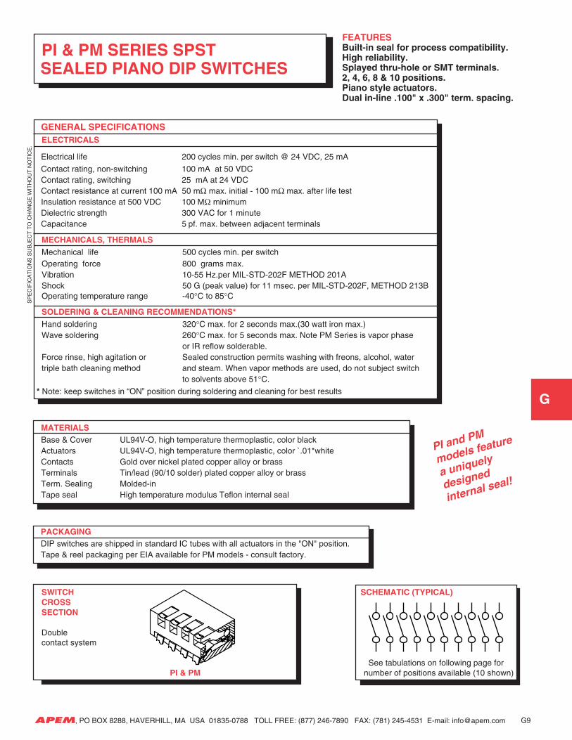
GENERAL SPECIFICATIONS ELECTRICALS
MECHANICALS, THERMALSMechanical life 500 cycles min. per switchOperating force 800 grams max.Vibration 10-55 Hz.per MIL-STD-202F METHOD 201AShock 50 G (peak value) for 11 msec. per MIL-STD-202F, METHOD 213BOperating temperature range -40°C to 85°C
SOLDERING & CLEANING RECOMMENDATIONS*Hand soldering 320°C max. for 2 seconds max.(30 watt iron max.)Wave soldering 260°C max. for 5 seconds max. Note PM Series is vapor phase
or IR reflow solderable.Force rinse, high agitation or Sealed construction permits washing with freons, alcohol, watertriple bath cleaning method and steam. When vapor methods are used, do not subject switch
to solvents above 51°C.
* Note: keep switches in “ON” position during soldering and cleaning for best results
MATERIALSBase & Cover UL94V-O, high temperature thermoplastic, color blackActuators UL94V-O, high temperature thermoplastic, color `.01*whiteContacts Gold over nickel plated copper alloy or brassTerminals Tin/lead (90/10 solder) plated copper alloy or brassTerm. Sealing Molded-inTape seal High temperature modulus Teflon internal seal
PACKAGING DIP switches are shipped in standard IC tubes with all actuators in the "ON" position. Tape & reel packaging per EIA available for PM models - consult factory.
PI & PM SERIES SPST SEALED PIANO DIP SWITCHES
FEATURESBuilt-in seal for process compatibility.High reliability.Splayed thru-hole or SMT terminals.2, 4, 6, 8 & 10 positions.Piano style actuators.Dual in-line .100" x .300" term. spacing.
Electrical life 200 cycles min. per switch @ 24 VDC, 25 mA
Contact rating, non-switching 100 mA at 50 VDCContact rating, switching 25 mA at 24 VDCContact resistance at current 100 mA 50 mΩ max. initial - 100 mΩ max. after life testInsulation resistance at 500 VDC 100 MΩ minimumDielectric strength 300 VAC for 1 minuteCapacitance 5 pf. max. between adjacent terminals
SWITCH SCHEMATIC (TYPICAL) CROSS SECTION
Double contact system
See tabulations on following page for PI & PM number of positions available (10 shown)
G9
PI and PM
models feature
a uniquely
designed
internal seal!
SP
EC
IFIC
AT
ION
S S
UB
JEC
T T
O C
HA
NG
E W
ITH
OU
T N
OT
ICE
.
G
APEM, PO BOX 8288, HAVERHILL, MA USA 01835-0788 TOLL FREE: (877) 246-7890 FAX: (781) 245-4531 E-mail: [email protected]
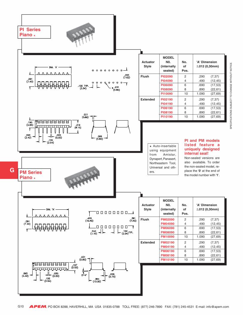
PI SeriesPiano
PM SeriesPiano
MODEL Actuator N0. No. 'A' Dimension Style (internally of ±.012 (0,30mm)
sealed) Pos.
Flush PI02090 2 .290 (7,37)PI04090 4 .490 (12,45)PI06090 6 .690 (17,53)PI08090 8 .890 (22,61)PI10090 10 1.090 (27,69)
Extended PI02190 2 .290 (7,37)PI04190 4 .490 (12,45)PI06190 6 .690 (17,53)PI08190 8 .890 (22,61)PI10190 10 1.090 (27,69)
MODEL Actuator N0. No. 'A' Dimension Style (internally of ±.012 (0,30mm)
sealed) Pos.
Flush PM02090 2 .290 (7,37)PM04090 4 .490 (12,45)PM06090 6 .690 (17,53)PM08090 8 .890 (22,61)PM10090 10 1.090 (27,69)
Extended PM02190 2 .290 (7,37)PM04190 4 .490 (12,45)PM06190 6 .690 (17,53)PM08190 8 .890 (22,61)PM10190 10 1.090 (27,69)
Auto-insertableusing equipmentfrom Amistar,Dynapert, Panasert,Northeastern Tool,Universal and oth-ers.
G10
PI and PM modelslisted feature auniquely designedinternal seal!Non-sealed versions arealso available. To orderthe non-sealed model, re-place the '0' at the end ofthe model number with '1'.
SP
EC
IFIC
AT
ION
S S
UB
JEC
T T
O C
HA
NG
E W
ITH
OU
T N
OT
ICE
.
G
APEM, PO BOX 8288, HAVERHILL, MA USA 01835-0788 TOLL FREE: (877) 246-7890 FAX: (781) 245-4531 E-mail: [email protected]
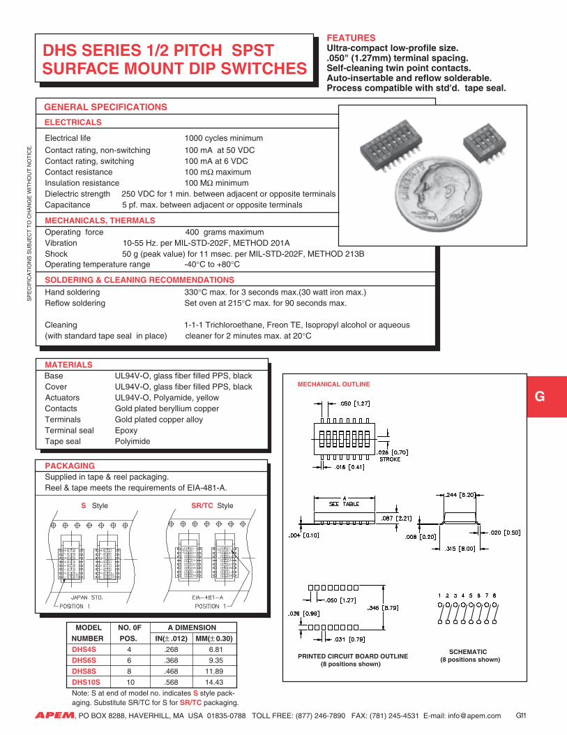
FEATURESUltra-compact low-profile size..050" (1.27mm) terminal spacing.Self-cleaning twin point contacts.Auto-insertable and reflow solderable.Process compatible with std'd. tape seal.
GENERAL SPECIFICATIONS
ELECTRICALS
Electrical life 1000 cycles minimum
Contact rating, non-switching 100 mA at 50 VDCContact rating, switching 100 mA at 6 VDCContact resistance 100 mΩ maximumInsulation resistance 100 MΩ minimumDielectric strength 250 VDC for 1 min. between adjacent or opposite terminalsCapacitance 5 pf. max. between adjacent or opposite terminals
MECHANICALS, THERMALSOperating force 400 grams maximumVibration 10-55 Hz. per MIL-STD-202F, METHOD 201AShock 50 g (peak value) for 11 msec. per MIL-STD-202F, METHOD 213BOperating temperature range -40°C to +80°C
SOLDERING & CLEANING RECOMMENDATIONSHand soldering 330°C max. for 3 seconds max.(30 watt iron max.)Reflow soldering Set oven at 215°C max. for 90 seconds max.
Cleaning 1-1-1 Trichloroethane, Freon TE, Isopropyl alcohol or aqueous(with standard tape seal in place) cleaner for 2 minutes max. at 20°C
MATERIALS Base UL94V-O, glass fiber filled PPS, black Cover UL94V-O, glass fiber filled PPS, black Actuators UL94V-O, Polyamide, yellow
Contacts Gold plated beryllium copperTerminals Gold plated copper alloyTerminal seal Epoxy
Tape seal Polyimide
PACKAGINGSupplied in tape & reel packaging.Reel & tape meets the requirements of EIA-481-A.
DHS SERIES 1/2 PITCH SPST SURFACE MOUNT DIP SWITCHES
MODEL NO. 0F A DIMENSION
NUMBER POS. IN(± .012) MM(± 0.30)
DHS4S 4 .268 6.81
DHS6S 6 .368 9.35
DHS8S 8 .468 11.89
DHS10S 10 .568 14.43
Note: S at end of model no. indicates S style pack-aging. Substitute SR/TC for S for SR/TC packaging.
MECHANICAL OUTLINE
PRINTED CIRCUIT BOARD OUTLINE (8 positions shown)
SCHEMATIC (8 positions shown)
G11
S Style SR/TC Style
SP
EC
IFIC
AT
ION
S S
UB
JEC
T T
O C
HA
NG
E W
ITH
OU
T N
OT
ICE
.
G
APEM, PO BOX 8288, HAVERHILL, MA USA 01835-0788 TOLL FREE: (877) 246-7890 FAX: (781) 245-4531 E-mail: [email protected]
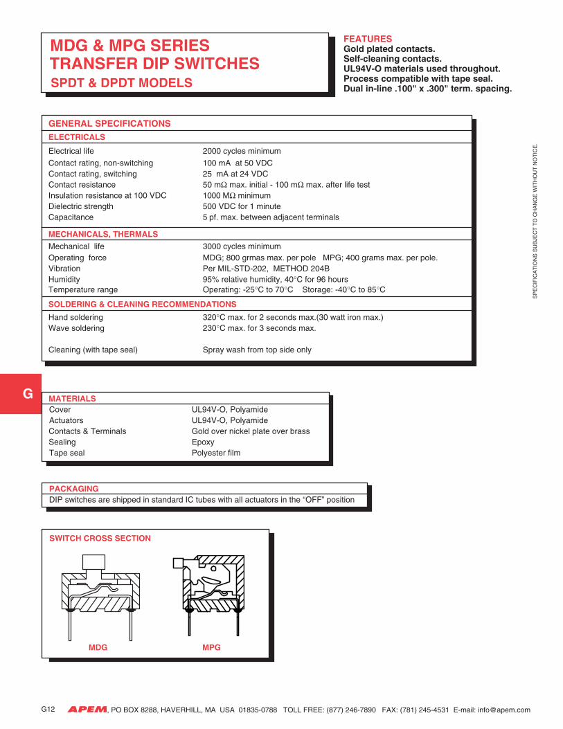
FEATURESGold plated contacts.Self-cleaning contacts.UL94V-O materials used throughout.Process compatible with tape seal.Dual in-line .100" x .300" term. spacing.
GENERAL SPECIFICATIONSELECTRICALS
Electrical life 2000 cycles minimum
Contact rating, non-switching 100 mA at 50 VDCContact rating, switching 25 mA at 24 VDCContact resistance 50 mΩ max. initial - 100 mΩ max. after life testInsulation resistance at 100 VDC 1000 MΩ minimumDielectric strength 500 VDC for 1 minuteCapacitance 5 pf. max. between adjacent terminals
MECHANICALS, THERMALSMechanical life 3000 cycles minimumOperating force MDG; 800 grmas max. per pole MPG; 400 grams max. per pole.Vibration Per MIL-STD-202, METHOD 204BHumidity 95% relative humidity, 40°C for 96 hoursTemperature range Operating: -25°C to 70°C Storage: -40°C to 85°C
SOLDERING & CLEANING RECOMMENDATIONS
Hand soldering 320°C max. for 2 seconds max.(30 watt iron max.)Wave soldering 230°C max. for 3 seconds max.
Cleaning (with tape seal) Spray wash from top side only
SWITCH CROSS SECTION
MDG MPG
MATERIALSCover UL94V-O, PolyamideActuators UL94V-O, Polyamide
Contacts & Terminals Gold over nickel plate over brass Sealing Epoxy
Tape seal Polyester film
PACKAGINGDIP switches are shipped in standard IC tubes with all actuators in the “OFF” position
MDG & MPG SERIES TRANSFER DIP SWITCHES SPDT & DPDT MODELS
G12
SP
EC
IFIC
AT
ION
S S
UB
JEC
T T
O C
HA
NG
E W
ITH
OU
T N
OT
ICE
.
G
APEM, PO BOX 8288, HAVERHILL, MA USA 01835-0788 TOLL FREE: (877) 246-7890 FAX: (781) 245-4531 E-mail: [email protected]
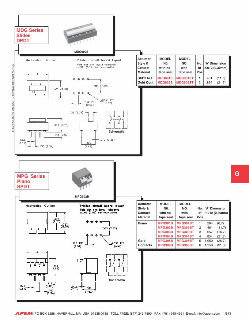
Actuator MODEL MODEL Style & N0. NO. No. 'A' Dimension Contact with no with of ±.012 (0,30mm)
Material tape seal tape seal Pos.
Piano MPG301B MPG301BT 1 .264 (6,7)MPG302B MPG302BT 2 .461 (11,7)MPG303B MPG303BT 3 .657 (16,7)MPG304B MPG304BT 4 .854 (21,7)
Gold MPG305B MPG305BT 5 1.050 (26,7)Contacts MPG306B MPG306BT 6 1.250 (31,8)
MPG SeriesPianoSPDT
G13
MPG302B
MDG SeriesSlidesDPDT
MDG602S
Actuator MODEL MODEL Style & N0. NO. No. ‘A' Dimension Contact with no with of ±.012 (0,30mm)
Material tape seal tape seal Pos.
Std'd Act. MDG601S MDG601ST 1 .461 (11,7)Gold Cont. MDG602S MDG602ST 2 .854 (21,7)
SP
EC
IFIC
AT
ION
S S
UB
JEC
T T
O C
HA
NG
E W
ITH
OU
T N
OT
ICE
.
G
APEM, PO BOX 8288, HAVERHILL, MA USA 01835-0788 TOLL FREE: (877) 246-7890 FAX: (781) 245-4531 E-mail: [email protected]
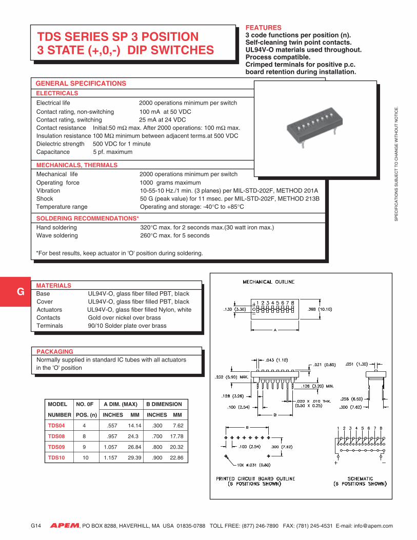
FEATURES3 code functions per position (n).Self-cleaning twin point contacts.UL94V-O materials used throughout.Process compatible.Crimped terminals for positive p.c.board retention during installation.
MODEL NO. 0F A DIM. (MAX) B DIMENSION
NUMBER POS. (n) INCHES MM INCHES MM
TDS04 4 .557 14.14 .300 7.62
TDS08 8 .957 24.3 .700 17.78
TDS09 9 1.057 26.84 .800 20.32
TDS10 10 1.157 29.39 .900 22.86
MATERIALS Base UL94V-O, glass fiber filled PBT, black Cover UL94V-O, glass fiber filled PBT, black Actuators UL94V-O, glass fiber filled Nylon, white
Contacts Gold over nickel over brassTerminals 90/10 Solder plate over brass
PACKAGINGNormally supplied in standard IC tubes with all actuators
in the 'O' position
TDS SERIES SP 3 POSITION3 STATE (+,0,-) DIP SWITCHES
G14
GENERAL SPECIFICATIONS ELECTRICALS
Electrical life 2000 operations minimum per switch
Contact rating, non-switching 100 mA at 50 VDCContact rating, switching 25 mA at 24 VDCContact resistance Initial:50 mΩ max. After 2000 operations: 100 mΩ max.Insulation resistance 100 MΩ minimum between adjacent terms.at 500 VDCDielectric strength 500 VDC for 1 minuteCapacitance 5 pf. maximum
MECHANICALS, THERMALSMechanical life 2000 operations minimum per switchOperating force 1000 grams maximumVibration 10-55-10 Hz./1 min. (3 planes) per MIL-STD-202F, METHOD 201AShock 50 G (peak value) for 11 msec. per MIL-STD-202F, METHOD 213B
Temperature range Operating and storage: -40°C to +85°C
SOLDERING RECOMMENDATIONS*Hand soldering 320°C max. for 2 seconds max.(30 watt iron max.)Wave soldering 260°C max. for 5 seconds
*For best results, keep actuator in 'O' position during soldering.
SP
EC
IFIC
AT
ION
S S
UB
JEC
T T
O C
HA
NG
E W
ITH
OU
T N
OT
ICE
.
G
APEM, PO BOX 8288, HAVERHILL, MA USA 01835-0788 TOLL FREE: (877) 246-7890 FAX: (781) 245-4531 E-mail: [email protected]
GENERAL SPECIFICATIONS ELECTRICALS
Operating voltage 24 VDC max.Contact rating, static 400 mA max.Contact rating, dynamic 100 mA max.Test voltage 250V 50Hz/1 min.Initial contact resistance < 100 milliohmsInsulation resistance > 100 megohms
MECHANICALS, THERMALS
Torque 0.98 inch-oz. min. (0.7 Ncm min.)Expected life 10,000 switching operationsContact force 15 grams min.Operating temperature range -30°C to 90°C
SOLDERING RECOMMENDATIONS
Hand soldering 340°C max. for 2 seconds max.(40 watt iron max.)
Wave soldering 260°C max. for 10 seconds max.Reflow soldering (SMT) 215°C max. for 40 seconds max.Solvent washing Freons or alcohol. (Do not use
chlorinated solvents)Aqueous cleaning Deionized water preferred
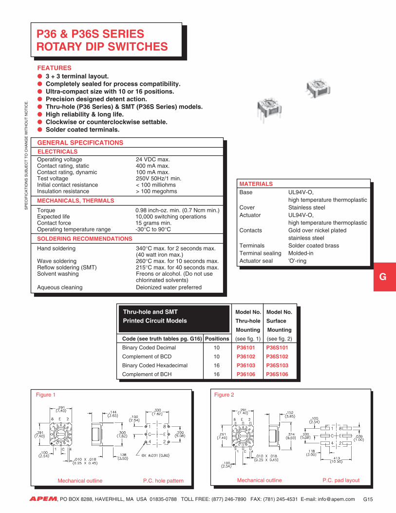
P36 & P36S SERIES ROTARY DIP SWITCHES
FEATURES 3 + 3 terminal layout. Completely sealed for process compatibility. Ultra-compact size with 10 or 16 positions. Precision designed detent action. Thru-hole (P36 Series) & SMT (P36S Series) models. High reliability & long life. Clockwise or counterclockwise settable. Solder coated terminals.
MATERIALSBase UL94V-O,
high temperature thermoplasticCover Stainless steelActuator UL94V-O,
high temperature thermoplasticContacts Gold over nickel plated
stainless steelTerminals Solder coated brassTerminal sealing Molded-inActuator seal 'O'-ring
G15
Mechanical outline P.C. pad layout Mechanical outline P.C. hole pattern
Figure 1 Figure 2
Thru-hole and SMT Model No. Model No.
Printed Circuit Models Thru-hole Surface
Mounting Mounting
Code (see truth tables pg. G16) Positions (see fig. 1) (see fig. 2)
Binary Coded Decimal 10 P36101 P36S101
Complement of BCD 10 P36102 P36S102
Binary Coded Hexadecimal 16 P36103 P36S103
Complement of BCH 16 P36106 P36S106
SP
EC
IFIC
AT
ION
S S
UB
JEC
T T
O C
HA
NG
E W
ITH
OU
T N
OT
ICE
.
G
APEM, PO BOX 8288, HAVERHILL, MA USA 01835-0788 TOLL FREE: (877) 246-7890 FAX: (781) 245-4531 E-mail: [email protected]
* 'None' indicates no option suffix is required.
CODES
COMP. OF BINARY CODED HEXADEC. (06) 16 Positions Dial No. 1 2 4 8
0
1
2
3
4
5
6
7
8
9
A
B
C
D
E
F
BINARY CODED DECIMAL (01) 10 Positions Dial No. 1 2 4 8
01
2
3
4
5
6
7
8
9
BINARY CODED HEXADECIMAL (03) 16 Positions Dial No. 1 2 4 8
01
2
3
4
5
6
7
8
9
A
B
C
D
E
F
COMP. OF BINARY CODED DECIMAL (02) 10 Positions Dial No. 1 2 4 8
0
1
2
3
4
5
6
7
8
9
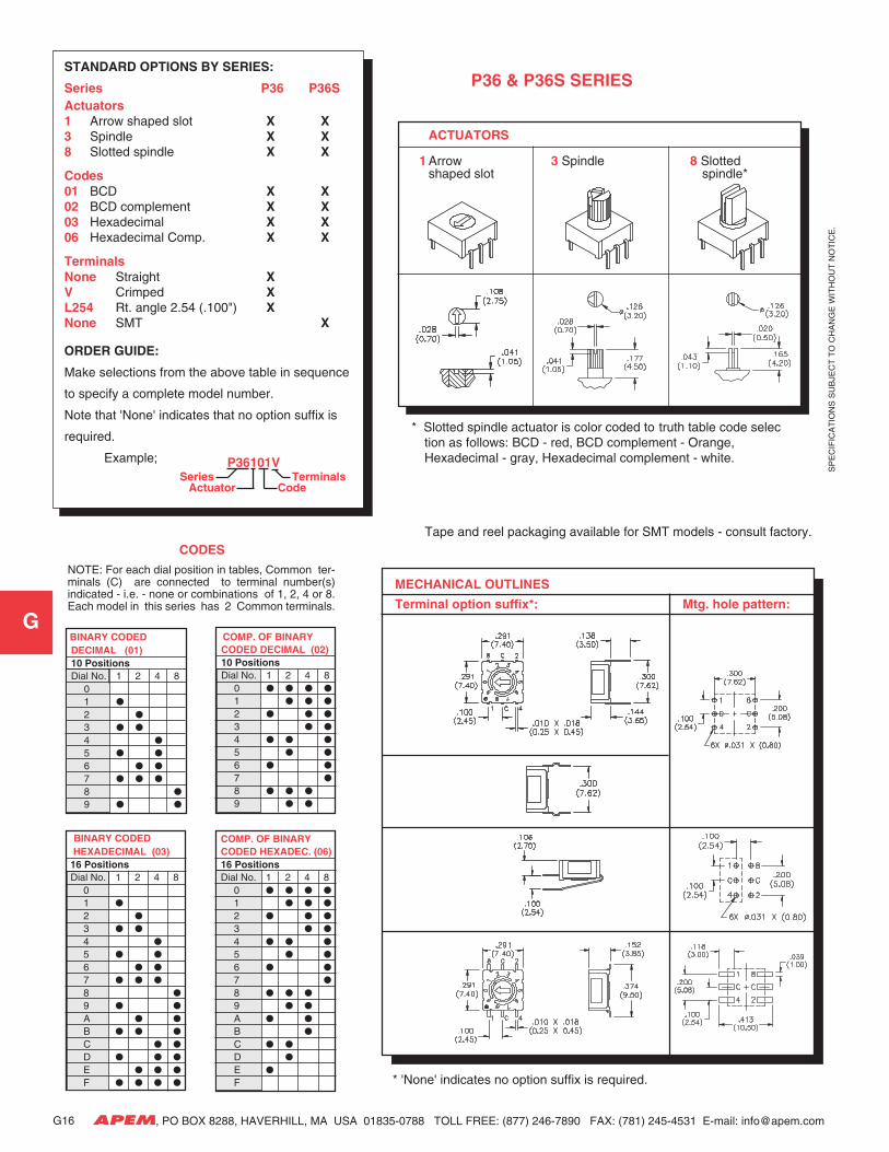
NOTE: For each dial position in tables, Common ter-minals (C) are connected to terminal number(s)indicated - i.e. - none or combinations of 1, 2, 4 or 8.Each model in this series has 2 Common terminals.
STANDARD OPTIONS BY SERIES:
Series P36 P36SActuators1 Arrow shaped slot X X3 Spindle X X8 Slotted spindle X X
Codes01 BCD X X02 BCD complement X X03 Hexadecimal X X06 Hexadecimal Comp. X X
TerminalsNone Straight XV Crimped XL254 Rt. angle 2.54 (.100") XNone SMT X
ORDER GUIDE:
Make selections from the above table in sequence
to specify a complete model number.
Note that 'None' indicates that no option suffix is
required.
Example;
P36 & P36S SERIES
P36101V
ActuatorTerminals
CodeSeries
ACTUATORS
1 Arrow 3 Spindle 8 Slottedshaped slot spindle*
* Slotted spindle actuator is color coded to truth table code selection as follows: BCD - red, BCD complement - Orange,Hexadecimal - gray, Hexadecimal complement - white.
MECHANICAL OUTLINES
Terminal option suffix*: Mtg. hole pattern:
Tape and reel packaging available for SMT models - consult factory.
SP
EC
IFIC
AT
ION
S S
UB
JEC
T T
O C
HA
NG
E W
ITH
OU
T N
OT
ICE
.
G
APEM, PO BOX 8288, HAVERHILL, MA USA 01835-0788 TOLL FREE: (877) 246-7890 FAX: (781) 245-4531 E-mail: [email protected]
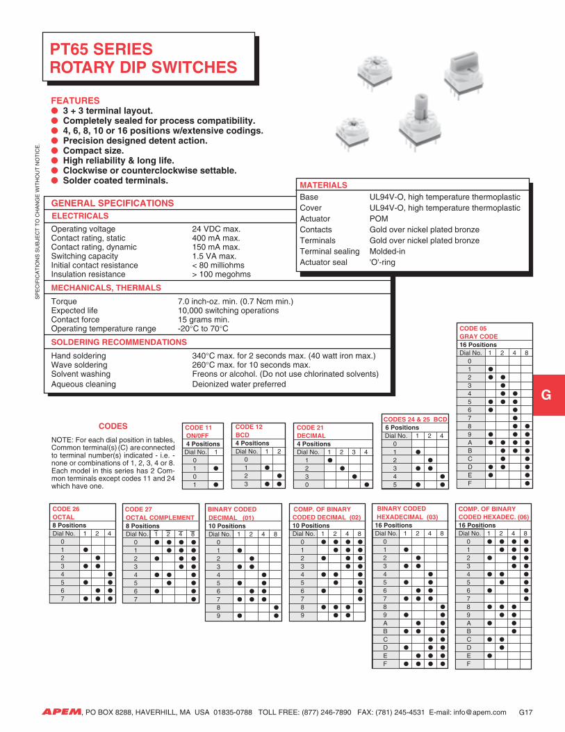
PT65 SERIES ROTARY DIP SWITCHES
GENERAL SPECIFICATIONS ELECTRICALS
Operating voltage 24 VDC max.Contact rating, static 400 mA max.Contact rating, dynamic 150 mA max.Switching capacity 1.5 VA max.Initial contact resistance < 80 milliohmsInsulation resistance > 100 megohms
MECHANICALS, THERMALS
Torque 7.0 inch-oz. min. (0.7 Ncm min.)Expected life 10,000 switching operationsContact force 15 grams min.Operating temperature range -20°C to 70°C
SOLDERING RECOMMENDATIONS
Hand soldering 340°C max. for 2 seconds max. (40 watt iron max.)Wave soldering 260°C max. for 10 seconds max.Solvent washing Freons or alcohol. (Do not use chlorinated solvents)Aqueous cleaning Deionized water preferred
CODE 11 ON/0FF 4 Positions Dial No. 1
01
01
CODE 21 DECIMAL 4 Positions Dial No. 1 2 3 4
1
2
3
0
CODE 05 GRAY CODE 16 Positions Dial No. 1 2 4 8
01
2
3
4
5
6
7
8
9
A
B
C
D
E
F
COMP. OF BINARY CODED HEXADEC. (06) 16 Positions Dial No. 1 2 4 8
0
1
2
3
4
5
6
7
8
9
A
B
C
D
E
F
CODES CODE 12 BCD 4 Positions Dial No. 1 2
01
2
3
FEATURES 3 + 3 terminal layout. Completely sealed for process compatibility. 4, 6, 8, 10 or 16 positions w/extensive codings. Precision designed detent action. Compact size. High reliability & long life. Clockwise or counterclockwise settable. Solder coated terminals. MATERIALS
Base UL94V-O, high temperature thermoplasticCover UL94V-O, high temperature thermoplasticActuator POMContacts Gold over nickel plated bronzeTerminals Gold over nickel plated bronzeTerminal sealing Molded-inActuator seal 'O'-ring
CODES 24 & 25 BCD 6 Positions Dial No. 1 2 4
01
2
3
4
5
BINARY CODED DECIMAL (01) 10 Positions Dial No. 1 2 4 8
01
2
3
4
5
6
7
8
9
CODE 26 OCTAL 8 Positions Dial No. 1 2 4
01
2
3
4
5
6
7
G17
COMP. OF BINARY CODED DECIMAL (02) 10 Positions Dial No. 1 2 4 8
0
1
2
3
4
5
6
7
8
9
CODE 27 OCTAL COMPLEMENT 8 Positions Dial No. 1 2 4 8
0
1
2
3
4
5
6
7
NOTE: For each dial position in tables,Common terminal(s) (C) are connectedto terminal number(s) indicated - i.e. -none or combinations of 1, 2, 3, 4 or 8.Each model in this series has 2 Com-mon terminals except codes 11 and 24which have one.
BINARY CODED HEXADECIMAL (03) 16 Positions Dial No. 1 2 4 8
01
2
3
4
5
6
7
8
9
A
B
C
D
E
F
SP
EC
IFIC
AT
ION
S S
UB
JEC
T T
O C
HA
NG
E W
ITH
OU
T N
OT
ICE
.
G
APEM, PO BOX 8288, HAVERHILL, MA USA 01835-0788 TOLL FREE: (877) 246-7890 FAX: (781) 245-4531 E-mail: [email protected]
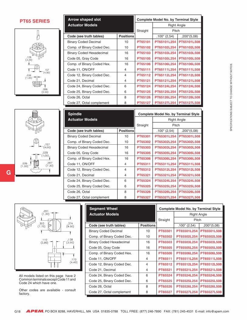
Arrow shaped slot Complete Model No. by Terminal Style
Actuator Models Right Angle
Straight Pitch
Code (see truth tables) Positions .100" (2,54) .200"(5,08)
Binary Coded Decimal 10 PT65101 PT65101L254 PT65101L508
Comp. of Binary Coded Dec. 10 PT65102 PT65102L254 PT65102L508
Binary Coded Hexadecimal 16 PT65103 PT65103L254 PT65103L508
Code 05, Gray Code 16 PT65105 PT65105L254 PT65105L508
Comp. of Binary Coded Hex. 16 PT65106 PT65106L254 PT65106L508
Code 11, ON/OFF 4 PT65111 PT65111L254 PT65111L508
Code 12, Binary Coded Dec. 4 PT65112 PT65112L254 PT65112L508
Code 21, Decimal 4 PT65121 PT65121L254 PT65121L508
Code 24, Binary Coded Dec. 6 PT65124 PT65124L254 PT65124L508
Code 25, Binary Coded Dec. 6 PT65125 PT65125L254 PT65125L508
Code 26, Octal 8 PT65126 PT65126L254 PT65126L508
Code 27, Octal complement 8 PT65127 PT65127L254 PT65127L508
Spindle Complete Model No. by Terminal Style
Actuator Models Right Angle
Straight Pitch
Code (see truth tables) Positions .100" (2,54) .200"(5,08)
Binary Coded Decimal 10 PT65301 PT65301L254 PT65301L508
Comp. of Binary Coded Dec. 10 PT65302 PT65302L254 PT65302L508
Binary Coded Hexadecimal 16 PT65303 PT65303L254 PT65303L508
Code 05, Gray Code 16 PT65305 PT65305L254 PT65305L508
Comp. of Binary Coded Hex. 16 PT65306 PT65306L254 PT65306L508
Code 11, ON/OFF 4 PT65311 PT65311L254 PT65311L508
Code 12, Binary Coded Dec. 4 PT65312 PT65312L254 PT65312L508
Code 21, Decimal 4 PT65321 PT65321L254 PT65321L508
Code 24, Binary Coded Dec. 6 PT65324 PT65324L254 PT65324L508
Code 25, Binary Coded Dec. 6 PT65325 PT65325L254 PT65325L508
Code 26, Octal 8 PT65326 PT65326L254 PT65326L508
Code 27, Octal complement 8 PT65327 PT65327L254 PT65327L508
Segment Wheel Complete Model No. by Terminal Style
Actuator Models Right Angle
Straight Pitch
Code (see truth tables) Positions .100" (2,54) .200"(5,08)
Binary Coded Decimal 10 PT65501 PT65501L254 PT65501L508
Comp. of Binary Coded Dec. 10 PT65502 PT65502L254 PT65502L508
Binary Coded Hexadecimal 16 PT65503 PT65503L254 PT65503L508
Code 05, Gray Code 16 PT65505 PT65505L254 PT65505L508
Comp. of Binary Coded Hex. 16 PT65506 PT65506L254 PT65506L508
Code 11, ON/OFF 4 PT65511 PT65511L254 PT65511L508
Code 12, Binary Coded Dec. 4 PT65512 PT65512L254 PT65512L508
Code 21, Decimal 4 PT65521 PT65521L254 PT65521L508
Code 24, Binary Coded Dec. 6 PT65524 PT65524L254 PT65524L508
Code 25, Binary Coded Dec. 6 PT65525 PT65525L254 PT65525L508
Code 26, Octal 8 PT65526 PT65526L254 PT65526L508
Code 27, Octal complement 8 PT65527 PT65527L254 PT65527L508
All models listed on this page have 2Common terminals except Code 11 andCode 24 which have one.
Other codes are available - consultfactory.
G18
PT65 SERIES
SP
EC
IFIC
AT
ION
S S
UB
JEC
T T
O C
HA
NG
E W
ITH
OU
T N
OT
ICE
.
G
APEM, PO BOX 8288, HAVERHILL, MA USA 01835-0788 TOLL FREE: (877) 246-7890 FAX: (781) 245-4531 E-mail: [email protected]
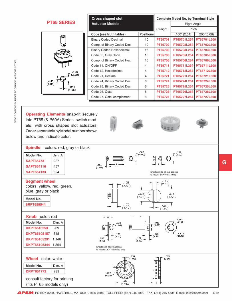
Cross shaped slot Complete Model No. by Terminal Style
Actuator Models Right Angle
Straight Pitch
Code (see truth tables) Positions .100" (2,54) .200"(5,08)
Binary Coded Decimal 10 PT65701 PT65701L254 PT65701L508
Comp. of Binary Coded Dec. 10 PT65702 PT65702L254 PT65702L508
Binary Coded Hexadecimal 16 PT65703 PT65703L254 PT65703L508
Code 05, Gray Code 16 PT65705 PT65705L254 PT65705L508
Comp. of Binary Coded Hex. 16 PT65706 PT65706L254 PT65706L508
Code 11, ON/OFF 4 PT65711 PT65711L254 PT65711L508
Code 12, Hexadecimal 4 PT65712 PT65712L254 PT65712L508
Code 21, Decimal 4 PT65721 PT65721L254 PT65721L508
Code 24, Binary Coded Dec. 6 PT65724 PT65724L254 PT65724L508
Code 25, Binary Coded Dec. 6 PT65725 PT65725L254 PT65725L508
Code 26, Octal 8 PT65726 PT65726L254 PT65726L508
Code 27, Octal complement 8 PT65727 PT65727L254 PT65727L508
G19
PT65 SERIES
Operating Elements snap-fit securelyinto PT65 (& P60A) Series switch mod-els with cross shaped slot actuators.Order separately by Model number shownbelow and indicate color.
Spindle colors: red, gray or black
Segment wheelcolors: yellow, red, green,blue, gray or black
Knob color: red
Wheel color: white
consult factory for printing (fits PT65 models only)
Model No. Dim. A
SAPT65473 .287
SAPT654116 .457
SAPT654133 .524
Model No. Dim. A
DKPT6510553 .209
DKPT65105157 .618
DKPT65105291 1.146
DKPT65105344 1.354
Model No. Dim. A
DRPT651772 .283
Short spindle above appliesto model SAPT65473 only
Short knob above appliesto model DKPT6510553 only
Model No.
SRPT659544
SP
EC
IFIC
AT
ION
S S
UB
JEC
T T
O C
HA
NG
E W
ITH
OU
T N
OT
ICE
.
G
APEM, PO BOX 8288, HAVERHILL, MA USA 01835-0788 TOLL FREE: (877) 246-7890 FAX: (781) 245-4531 E-mail: [email protected]
1
C 1
C
2
C
1
C
4
2
C
3
1
C 4
2 1
C
4 2
C
1
C
4 2
C
8
Code 11 Code 12 Code 21 Code 24 Codes 25 & 26 Code 27 and10& 16 pos. models
G20
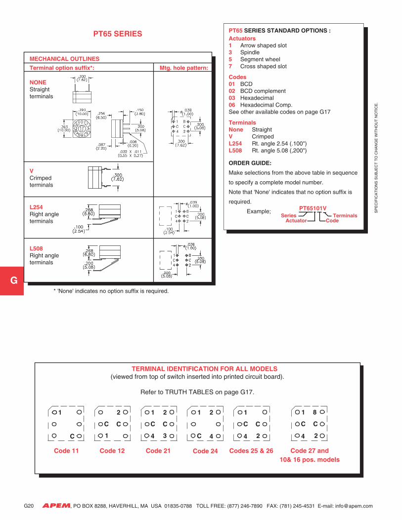
* 'None' indicates no option suffix is required.
PT65 SERIES STANDARD OPTIONS :Actuators1 Arrow shaped slot3 Spindle5 Segment wheel7 Cross shaped slot
Codes01 BCD02 BCD complement03 Hexadecimal06 Hexadecimal Comp.See other available codes on page G17
TerminalsNone StraightV CrimpedL254 Rt. angle 2.54 (.100")L508 Rt. angle 5.08 (,200")
ORDER GUIDE:
Make selections from the above table in sequence
to specify a complete model number.
Note that 'None' indicates that no option suffix is
required.
Example; PT65101V
Actuator CodeSeries Terminals
PT65 SERIES
TERMINAL IDENTIFICATION FOR ALL MODELS(viewed from top of switch inserted into printed circuit board).
Refer to TRUTH TABLES on page G17.
MECHANICAL OUTLINES
Terminal option suffix*: Mtg. hole pattern:
NONEStraightterminals
VCrimpedterminals
L254Right angleterminals
L508Right angleterminals
SP
EC
IFIC
AT
ION
S S
UB
JEC
T T
O C
HA
NG
E W
ITH
OU
T N
OT
ICE
.
G
APEM, PO BOX 8288, HAVERHILL, MA USA 01835-0788 TOLL FREE: (877) 246-7890 FAX: (781) 245-4531 E-mail: [email protected]
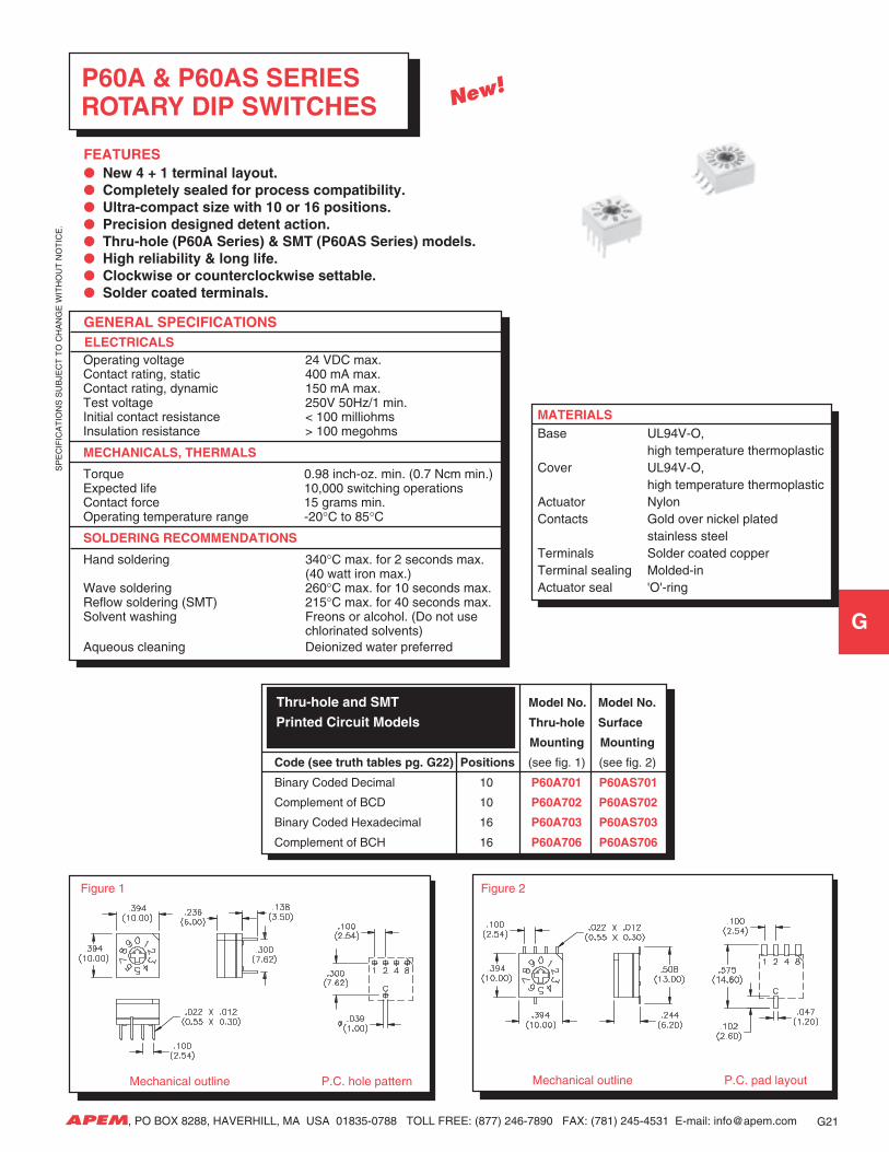
GENERAL SPECIFICATIONS ELECTRICALS
Operating voltage 24 VDC max.Contact rating, static 400 mA max.Contact rating, dynamic 150 mA max.Test voltage 250V 50Hz/1 min.Initial contact resistance < 100 milliohmsInsulation resistance > 100 megohms
MECHANICALS, THERMALS
Torque 0.98 inch-oz. min. (0.7 Ncm min.)Expected life 10,000 switching operationsContact force 15 grams min.Operating temperature range -20°C to 85°C
SOLDERING RECOMMENDATIONS
Hand soldering 340°C max. for 2 seconds max.(40 watt iron max.)
Wave soldering 260°C max. for 10 seconds max.Reflow soldering (SMT) 215°C max. for 40 seconds max.Solvent washing Freons or alcohol. (Do not use
chlorinated solvents)Aqueous cleaning Deionized water preferred
P60A & P60AS SERIES ROTARY DIP SWITCHES
FEATURES New 4 + 1 terminal layout. Completely sealed for process compatibility. Ultra-compact size with 10 or 16 positions. Precision designed detent action. Thru-hole (P60A Series) & SMT (P60AS Series) models. High reliability & long life. Clockwise or counterclockwise settable. Solder coated terminals.
MATERIALSBase UL94V-O,
high temperature thermoplasticCover UL94V-O,
high temperature thermoplasticActuator NylonContacts Gold over nickel plated
stainless steelTerminals Solder coated copperTerminal sealing Molded-inActuator seal 'O'-ring
G21
Mechanical outline P.C. pad layout Mechanical outline P.C. hole pattern
Figure 1 Figure 2
Thru-hole and SMT Model No. Model No.
Printed Circuit Models Thru-hole Surface
Mounting Mounting
Code (see truth tables pg. G22) Positions (see fig. 1) (see fig. 2)
Binary Coded Decimal 10 P60A701 P60AS701
Complement of BCD 10 P60A702 P60AS702
Binary Coded Hexadecimal 16 P60A703 P60AS703
Complement of BCH 16 P60A706 P60AS706
New!
SP
EC
IFIC
AT
ION
S S
UB
JEC
T T
O C
HA
NG
E W
ITH
OU
T N
OT
ICE
.
G
APEM, PO BOX 8288, HAVERHILL, MA USA 01835-0788 TOLL FREE: (877) 246-7890 FAX: (781) 245-4531 E-mail: [email protected]
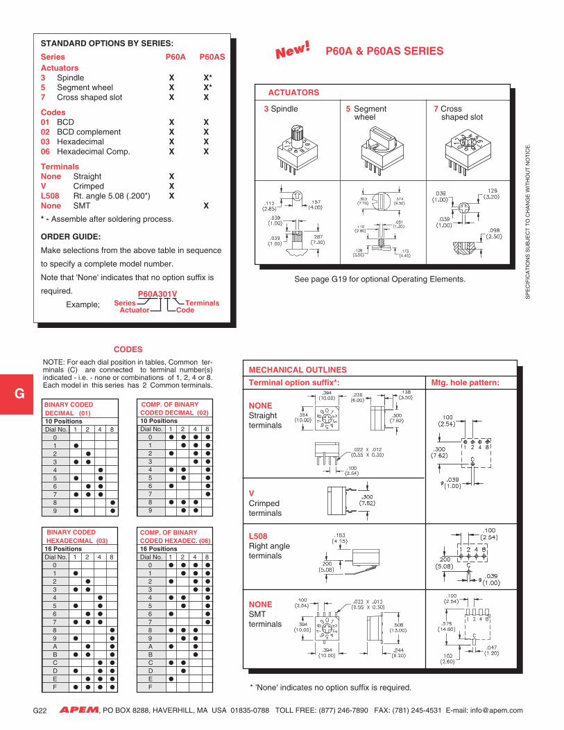
* 'None' indicates no option suffix is required.
CODES
COMP. OF BINARY CODED HEXADEC. (06) 16 Positions Dial No. 1 2 4 8
0
1
2
3
4
5
6
7
8
9
A
B
C
D
E
F
BINARY CODED DECIMAL (01) 10 Positions Dial No. 1 2 4 8
01
2
3
4
5
6
7
8
9
BINARY CODED HEXADECIMAL (03) 16 Positions Dial No. 1 2 4 8
01
2
3
4
5
6
7
8
9
A
B
C
D
E
F
COMP. OF BINARY CODED DECIMAL (02) 10 Positions Dial No. 1 2 4 8
0
1
2
3
4
5
6
7
8
9
NOTE: For each dial position in tables, Common ter-minals (C) are connected to terminal number(s)indicated - i.e. - none or combinations of 1, 2, 4 or 8.Each model in this series has 2 Common terminals.
STANDARD OPTIONS BY SERIES:
Series P60A P60ASActuators3 Spindle X X*5 Segment wheel X X*7 Cross shaped slot X X
Codes01 BCD X X02 BCD complement X X03 Hexadecimal X X06 Hexadecimal Comp. X X
TerminalsNone Straight XV Crimped XL508 Rt. angle 5.08 (.200") XNone SMT X
* - Assemble after soldering process.
ORDER GUIDE:
Make selections from the above table in sequence
to specify a complete model number.
Note that 'None' indicates that no option suffix is
required.
Example;
See page G19 for optional Operating Elements.
P60A301V
ActuatorTerminals
CodeSeries
P60A & P60AS SERIES
ACTUATORS
3 Spindle 5 Segment 7 Cross wheel shaped slot
MECHANICAL OUTLINES
Terminal option suffix*: Mtg. hole pattern:
NONEStraightterminals
VCrimpedterminals
L508Right angleterminals
NONESMTterminals
New!
SP
EC
IFIC
AT
ION
S S
UB
JEC
T T
O C
HA
NG
E W
ITH
OU
T N
OT
ICE
.
G
APEM, PO BOX 8288, HAVERHILL, MA USA 01835-0788 TOLL FREE: (877) 246-7890 FAX: (781) 245-4531 E-mail: [email protected]
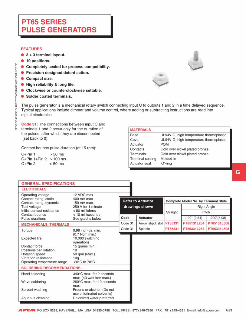
PT65 SERIES PULSE GENERATORS
FEATURES
3 + 3 terminal layout.
10 positions.
Completely sealed for process compatibility.
Precision designed detent action.
Compact size.
High reliability & long life.
Clockwise or counterclockwise settable.
Solder coated terminals.
G23
GENERAL SPECIFICATIONS ELECTRICALS
Operating voltage 12 VDC max.Contact rating, static 400 mA max.Contact rating, dynamic 150 mA max.Test voltage 250 V for 1 minuteInitial contact resistance < 80 milliohmsContact bounce < 10 millisecondsPulse durations See graphs below
MECHANICALS, THERMALS
Torque 0.98 inch-oz. min.(0.7 Ncm min.)
Expected life 10,000 switchingoperations
Contact force 15 grams min.Positions per rotation 10Rotation speed 50 rpm (Max.)Vibration resistance 10gOperating temperature range -20°C to 70°C
SOLDERING RECOMMENDATIONS
Hand soldering 340°C max. for 2 secondsmax. (40 watt iron max.)
Wave soldering 260°C max. for 10 secondsmax.
Solvent washing Freons or alcohol. (Do notuse chlorinated solvents)
Aqueous cleaning Deionized water preferred
Refer to Actuator Complete Model No. by Terminal Style
drawings shown Right Angle
Straight Pitch
Code Actuator .100" (2,54) .200"(5,08)
Code 31 Arrow shpd. slot PT65131 PT65131L254 PT65131L508
Code 31 Spindle PT65331 PT65331L254 PT65331L508
MATERIALSBase UL94V-O, high temperature thermoplasticCover UL94V-O, high temperature thermoplasticActuator POMContacts Gold over nickel plated bronzeTerminals Gold over nickel plated bronzeTerminal sealing Molded-inActuator seal 'O'-ring
The pulse generator is a mechanical rotary switch connecting input C to outputs 1 and 2 in a time delayed sequence.Typical applications include dimmer and volume control, where adding or subtracting instructions are read intodigital electronics.
Code 31: The connections between input C andterminals 1 and 2 occur only for the duration ofthe pulses, after which they are disconnected (set back to 0).
Contact bounce pulse duration (at 15 rpm):
C+Pin 1 > 50 msC+Pin 1+Pin 2 > 100 msC+Pin 2 > 50 ms
SP
EC
IFIC
AT
ION
S S
UB
JEC
T T
O C
HA
NG
E W
ITH
OU
T N
OT
ICE
.
G
APEM, PO BOX 8288, HAVERHILL, MA USA 01835-0788 TOLL FREE: (877) 246-7890 FAX: (781) 245-4531 E-mail: [email protected]
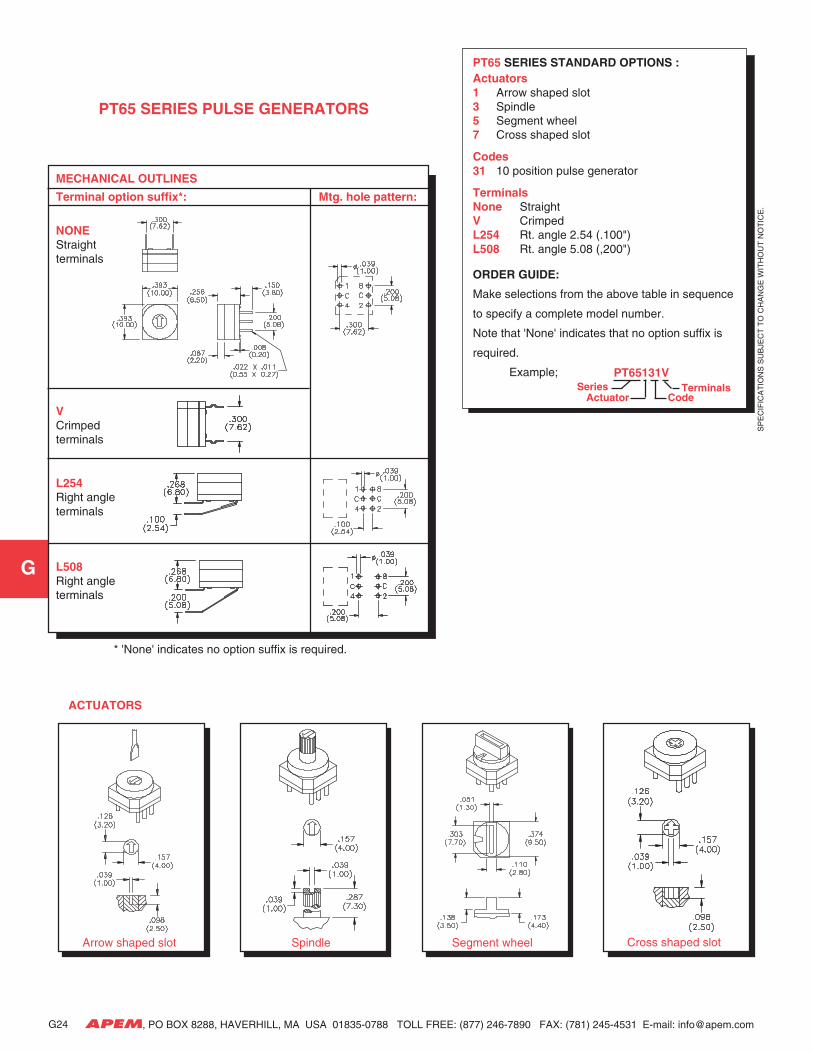
PT65 SERIES PULSE GENERATORS
Arrow shaped slot
G24
* 'None' indicates no option suffix is required.
PT65 SERIES STANDARD OPTIONS :Actuators1 Arrow shaped slot3 Spindle5 Segment wheel7 Cross shaped slot
Codes31 10 position pulse generator
TerminalsNone StraightV CrimpedL254 Rt. angle 2.54 (.100")L508 Rt. angle 5.08 (,200")
ORDER GUIDE:
Make selections from the above table in sequence
to specify a complete model number.
Note that 'None' indicates that no option suffix is
required.
Example; PT65131V
Actuator CodeSeries Terminals
ACTUATORS
Spindle Segment wheel Cross shaped slot
MECHANICAL OUTLINES
Terminal option suffix*: Mtg. hole pattern:
NONEStraightterminals
VCrimpedterminals
L254Right angleterminals
L508Right angleterminals