AP1000 Plant Overview · 2012-12-05 · Table 1-1 (Sheet 1 of 7) AP1000 Plant Comparison With Other...
32
AP1000 Plant Overview AP1000 Plant Overview AP1000 Technology Chapter 1.0 AP1000 Technology Chapter 1.0 1
Transcript of AP1000 Plant Overview · 2012-12-05 · Table 1-1 (Sheet 1 of 7) AP1000 Plant Comparison With Other...

AP1000 Plant OverviewAP1000 Plant OverviewAP1000 Technology Chapter 1.0AP1000 Technology Chapter 1.0
1

AP1000 Site Layout
2

AP1000 Plant Layout
3

Designed For Modular Construction
Module Type
Structural
Piping
Mechanical Equipment
Electrical Equipment
TOTAL
Number
122
154
55
11
342
4
TOTAL 342

Table 1-1 (Sheet 1 of 7)AP1000 Plant Comparison With Other Facilities
System/Component AP1000 Watts Bar San Onofre V. C. Summer
Overall Plant
Design Life (years) 60 40a 40a 40a
NSSS Power (MWt) 3,415 3,475 3,410 2,912
Core Power 3,400 3,459 3,390 2,900
5
Net MWe 1,090 1,218 1,100 950
RCS Operating Pressure (psia)
2,250 2,250 2,250 2,250
Thot (°F) 615 619 611 622
SG Design Pressure (psia) 1200 1200 1200 1200
Feedwater Temperature (°F)
440 442 445 440
Notes:a. Plus 20 years life extension

Sizewell B AP1000
AP1000 vs Current Site Layouts
6
74147A

Reactor Coolant System
7

Core and RCS• Fuel, Internals, Reactor Vessel
– 14-ft XL Robust Fuel – No bottom-mounted instrumentation– 60-year design life
• Steam Generators – Similar to large W/CE SGs in operation
• System 80 ANO RSG
8
• System 80, ANO RSG
• Reactor Coolant Pumps– No shaft seals
• Simplified 2x4 Main Loop– Reduces welds by 50%, pipe supports by 80%
• Pressurizer– 2100 ft3 vs. 1800 ft3 for many existing plants

ContainmentLayout
9
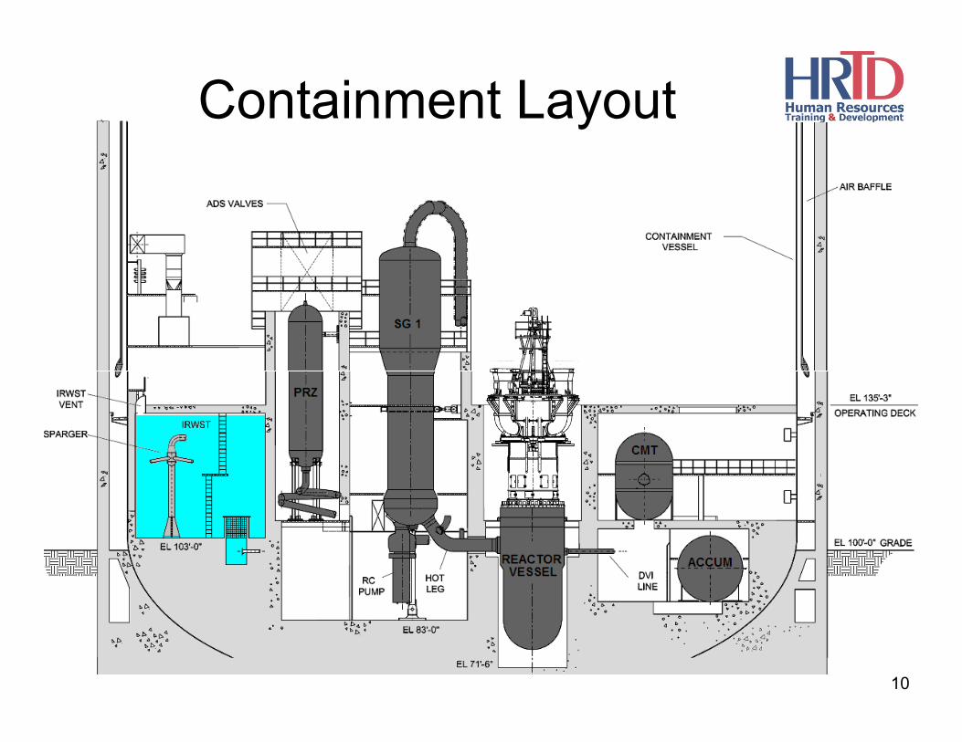
Containment Layout
10

Passive ContainmentCooling System (PCS)
• Steel containment vessel is part of passive safety system.
• PCS transfers heat from the shell to the environment.
• Water from Passive Containment Cooling Water Storage Tank (PCCWST) wets outer shell for 72 hours
11
outer shell for 72 hours.
• Natural convection air flow through containment annulus provides additional cooling.

Simplification of Safety Systems
12
Standard PWR AP1000

• Passive Residual Heat Removal Heat Exchanger (PRHRHX)– Natural circulation HX connected to RCS
• Passive Safety Injection (PXS)– Core Makeup Tanks (CMTs)
N i d l t
Passive Safety Features
13
– N2 pressurized accumulators– In-Containment Refueling Water Storage Tank
(IRWST)– Automatic Depressurization System (ADS) valves,
Pzr & HLs
• Passive Containment Cooling System (PCS)– Natural circulation of air / evaporation of water on
outside surface of steel containment vessel

14
AP1000 Passive Core Cooling System

Passive Cooling Systems• PRHRHX removes decay heat in event of
loss of SGs, transfers heat to IRWST contents.
• CMTs provide borated coolant flow at any
15
p ysystem pressure to vessel downcomer through direct vessel injection (DVI) lines.
• ADS actuates when CMT volume decreases to less than 67.5%.

Passive Cooling Systems (cont’d)
• Two accumulators provide borated coolant via DVI lines at high flow rates when RCS pressure is < 700 psia.
16
• IRWST supplies borated water to RCS via DVI lines once RCS is sufficiently depressurized.
Passive Safety Features: NoNeed for Safety-Related AC Power• Passive decay heat removal
– Natural circulation through PRHRHX connected to RCS
• Passive safety injection
17
– N2 pressurized accumulators
– Density-difference-driven flow from core makeup tanks
– Gravity drain from refueling water storage tank
– Automatic RCS depressurization (DC battery-backed electrically operated valves)

Passive Safety Features: NoNeed for Safety-Related AC Power
(cont’d)
• Passive containment cooling– Steel containment shell transfers heat to
t l i l ti f i d ti f
18
natural circulation of air and evaporation of water drained from storage tank by gravity

Primary Support Systems• Normal Residual Heat Removal System
(RNS)
• Component Cooling Water System (CCS)
• Service Water System (SWS)
19
• Fuel Handling and Storage System (FHS)
• Spent Fuel Pool Cooling System (SFS)
• Primary Sampling System (PSS)

• Turbine Building houses all traditional non-safety steam and power conversion systems– Condensate and feedwater system – Main steam system– Turbine-generator systems– Circulating water system
St t f d t t
Balance of Plant Features
– Startup feedwater system
• Turbine Building also houses active non-safety support systems– Component cooling water system– Service water system– Compressed and instrument air system– Demineralized water system
20

• BOP includes redundant non-safety diesels– Backup power to active non-safety systems
• Only a single source of off-site power is required
• No safety-related compressed air system
All t d i HVAC i f t
Balance of Plant Features (cont’d)
• All motor-driven HVAC is non-safety– Safety-related control room habitability system is
passive
• No active safety-related heat sink – ultimate heat sink is passive
• Smaller security perimeter
21
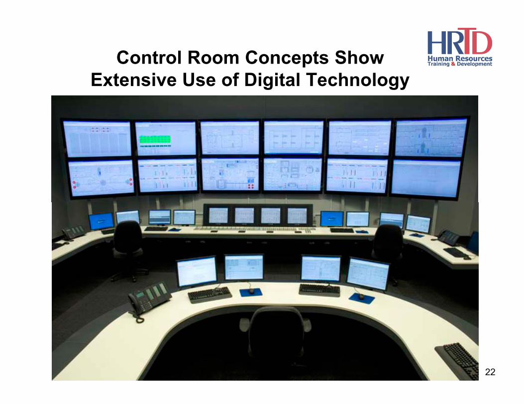
Control Room Concepts Show Extensive Use of Digital Technology
22

• Safety-related structures, systems, and components (SSCs) handled in similar manner as at current plants.
• Passive safety system performance uncertainties increase the importance of active (non-safety)
Regulatory Treatment of Non-Safety-Related Systems (RTNSS) Section 1.3
increase the importance of active (non safety) systems in providing defense-in-depth functions (SECY 94-084).
• The NRC and EPRI developed a process to identify the important active SSCs to maintain appropriate regulatory oversight of those SSCs.
23

• Effect on PRA: – Needed to meet NRC CDF (1E-4/yr) and LRF (1E-6/yr)
safety goals.
– Add margin to compensate for PRA uncertainty.
– Impact initiating event frequencies.
Non-safety SSCs are risk significant & candidates for RTNSS if:
Impact initiating event frequencies.
• Needed to meet 10CFR50.62, 50.63 requirements.
• Ensure long-term (> 72-hr) safety & address seismic events.
• Needed to meet containment performance goal.
• Prevent significant adverse system interactions.
24

• AP1000 SSCs identified as subject to RTNSS:– Diverse Actuation System (DAS)
– Normal Residual Heat Removal System (RNS)
– Component Cooling Water System (CCS)
– Service Water System (SWS)
Regulatory Treatment of Non-Safety-Related Systems (RTNSS) (cont’d)
y ( )
– Post-72-Hr Makeup Water Sources
– MCR & Instrumentation Room Fans
– Hydrogen Igniters
– Onsite and Offsite AC Power
– Ancillary DGs
– Non-1E DC & UPS for DAS
– Reactor Vessel Insulation (In-Vessel Retention)25

• Regulatory oversight methods in addition to ITAAC (Inspections, Tests, Analyses, and Acceptance Criteria) were determined as follows:– TS with an LCO is the appropriate operational regulatory
control for the manual DAS functions.
Regulatory Treatment of Non-Safety-Related Systems (RTNSS) (cont’d)
– Investment Protection Short-Term Availability Controls (STACs) provide administrative operational controls for the majority of the other SSCs.
– Design Reliability Assurance Program (D-RAP) - Quality assurance program for risk-important non-safety-related SSCs to provide reasonable assurance that the AP1000 is designed, procured, constructed, maintained, and operated in a manner consistent with the PRA.
26

• Inspection Considerations:– Inspections will be focused on those SSCs with targeted
ITAAC and findings would be documented.
– For findings associated with safety-related SSCs,
Regulatory Treatment of Non-Safety-Related Systems (RTNSS) (cont’d)
enforcement should be documented.
– Findings associated with non-safety-related SSCs would be considered a failure to meet commitments under the D-RAP.
27

USACurrent AP1000 Status
China
28

Today
29

AP1000 Standard Construction Schedule
30

Current US AP1000 Schedules/Plans
31

Westinghouse’s Projected Time Line
32


![AP1000 Installation Guide eng 040623 Guide_eng.pdf[Organization] The VoiceFinder AP1000 VoIP Gateway Installation Guide is offered to assist the ... VoiceFinder AP1000 VoIP Gateway](https://static.fdocuments.in/doc/165x107/6023a9082d103d7c1a084ddd/ap1000-installation-guide-eng-040623-guideengpdf-organization-the-voicefinder.jpg)