AP1000 European 11 Radioactive Waste Management … p… · AP1000 European 11. Radioactive Waste...
32
AP1000 European 11. Radioactive Waste Management Design Control Document EPS-GW-GL-700 11.5-1 Revision 1 11.5 Radiation Monitoring The radiation monitoring system (RMS) provides plant effluent monitoring, process fluid monitoring, airborne monitoring, and continuous indication of the radiation environment in plant areas where such information is needed. Radiation monitors that have a safety-related function are qualified environmentally, seismically, or both. Class 1E radiation monitors conform to the separation criteria described in subsection 8.3.2 and to the fire protection criteria described in subsection 9.5.1. Equipment qualification requirements, including seismic qualification requirements, and general location information for radiation monitors are listed in Section 3.11. Seismic Categories for the buildings housing radiation monitors are listed in Section 3.2. The radiation monitoring system is installed permanently and operates in conjunction with regular and special radiation survey programs to assist in meeting applicable regulatory requirements. The radiation monitoring system is designed in accordance with ANSI N13.1-1969. The process monitors are designed in accordance with ANSI-N42.18-1980. The radiation monitoring system is divided functionally into two subsystems: • Process, airborne, and effluent radiological monitoring and sampling • Area radiation monitoring 11.5.1 Design Basis 11.5.1.1 Safety Design Basis While the radiation monitoring system is primarily a surveillance system, certain detector channels perform safety-related functions. The components used in these channels meet the qualification requirements for safety-related equipment as described in subsection 7.1.4. Channel and equipment redundancy is provided for safety-related monitors to maintain the safety-related function in case of a single failure. The design objectives of the radiation monitoring system during postulated accidents are: • Initiate containment air filtration isolation in the event of abnormally high radiation inside the containment (High-1) • Initiate normal residual heat removal system suction line containment isolation in the event of abnormally high radiation inside the containment (High-2) • Initiate main control room supplemental filtration in the event of abnormally high gaseous radioactivity in the main control room supply air • Initiate main control room ventilation isolation and actuate the main control room emergency habitability system in the event of abnormally high particulate or iodine radioactivity in the main control room supply air
Transcript of AP1000 European 11 Radioactive Waste Management … p… · AP1000 European 11. Radioactive Waste...
AP1000 European 11. Radioactive Waste Management Design Control Document
EPS-GW-GL-700 11.5-1 Revision 1
11.5 Radiation Monitoring
The radiation monitoring system (RMS) provides plant effluent monitoring, process fluid monitoring, airborne monitoring, and continuous indication of the radiation environment in plant areas where such information is needed. Radiation monitors that have a safety-related function are qualified environmentally, seismically, or both. Class 1E radiation monitors conform to the separation criteria described in subsection 8.3.2 and to the fire protection criteria described in subsection 9.5.1. Equipment qualification requirements, including seismic qualification requirements, and general location information for radiation monitors are listed in Section 3.11. Seismic Categories for the buildings housing radiation monitors are listed in Section 3.2.
The radiation monitoring system is installed permanently and operates in conjunction with regular and special radiation survey programs to assist in meeting applicable regulatory requirements. The radiation monitoring system is designed in accordance with ANSI N13.1-1969. The process monitors are designed in accordance with ANSI-N42.18-1980.
The radiation monitoring system is divided functionally into two subsystems:
• Process, airborne, and effluent radiological monitoring and sampling • Area radiation monitoring
11.5.1 Design Basis
11.5.1.1 Safety Design Basis
While the radiation monitoring system is primarily a surveillance system, certain detector channels perform safety-related functions. The components used in these channels meet the qualification requirements for safety-related equipment as described in subsection 7.1.4.
Channel and equipment redundancy is provided for safety-related monitors to maintain the safety-related function in case of a single failure.
The design objectives of the radiation monitoring system during postulated accidents are:
• Initiate containment air filtration isolation in the event of abnormally high radiation inside the containment (High-1)
• Initiate normal residual heat removal system suction line containment isolation in the event of abnormally high radiation inside the containment (High-2)
• Initiate main control room supplemental filtration in the event of abnormally high gaseous radioactivity in the main control room supply air
• Initiate main control room ventilation isolation and actuate the main control room emergency habitability system in the event of abnormally high particulate or iodine radioactivity in the main control room supply air
AP1000 European 11. Radioactive Waste Management Design Control Document
EPS-GW-GL-700 11.5-2 Revision 1
• Provide long-term post-accident monitoring (using both safety-related and nonsafety-related monitors)
The scope of the radiation monitoring system for post-accident monitoring is set forth in General Design Criterion 64 and in the provisions of Regulatory Guide 1.97.
11.5.1.2 Power Generation Design Basis
The radiation monitoring system is designed to support the requirements of 10 CFR 20 and to provide:
• Equipment to meet the applicable regulatory requirements for both normal operation and transient events
• Data to aid plant health physics personnel in limiting release of radioactivity to the environment and limiting exposure of operation and maintenance personnel to meet ALARA (as-low-as-reasonably-achievable) guidance
• Early indication of a system or equipment malfunction that could result in excessive radiation dose to plant personnel or lead to plant damage
• Data collection and data storage to support compliance reporting for the applicable NRC requirements and guidelines, such as General Design Criterion 64 and Regulatory Guide 1.21.
• Exhausts to the environment from the personnel areas in the annex building, electrical and mechanical equipment rooms in the annex and auxiliary buildings, and the diesel generator rooms will not be radioactive because they contain no radioactive materials. These ventilation exhausts are not monitored.
11.5.2 System Description
11.5.2.1 Radiation Monitoring System
The radiation monitoring system uses distributed radiation monitors, where each radiation monitor consists of one or more radiation detectors and a dedicated radiation processor.
Each radiation processor receives, averages and stores radiation data and transmits alarms and data to the plant control system (protection and safety monitoring system for safety-related monitors) for control (as required), display and recording. These alarms include: low (fail), alert, and high. Selected channels have a rate-of-rise alarm. Storage of radiation readings is provided.
Each radiation detector, except the in-duct radiation detectors and the containment high range ion chambers, has a check source that is actuated from the associated local radiation processor. The check source is used to verify detector and monitor operation. The check source is shielded to meet ALARA requirements, and returns to its fully retracted/shielded position upon loss of actuator power. Check sources on detectors can be actuated from the main control room. The in-duct radiation detector operation may be checked using an internal LED to simulate light pulses

AP1000 European 11. Radioactive Waste Management Design Control Document
EPS-GW-GL-700 11.5-3 Revision 1
emitted in response to radiation. The containment high range monitors have an internal source that provides a minimum reading; loss of signal from the detector indicates detector inoperability.
Radiation monitoring data, including alarm status, are provided to AP1000 operators via the plant control system (and the protection and safety monitoring system for Class 1E monitors). The information is available in either counts per minute (count rate), microCuries/cc (activity concentration), or R/hr (radiation dose rate).
Safety-related channels are environmentally qualified and are powered from the Class 1E dc and uninterruptible power supply system. Nonsafety-related channels are powered from the non-Class 1E dc and uninterruptible power supply system.
11.5.2.2 Monitor Functional Description
The process and effluent radiological monitoring and sampling subsystem provides radiation monitoring for the four functional classifications listed below. Individual monitors may provide functionality in more than one of these classifications.
• Fluid process monitors determine concentrations of radioactive material in plant fluid systems
• Airborne monitors provide operators with information on concentrations of radioactivity at various points in the ventilation system, providing information on airborne concentrations in the plant
• Liquid and gaseous effluent monitors measure radioactive materials discharged to the environs
• Post-accident monitors monitor potential pathways for release of radioactive materials during accident conditions
The area radiation monitoring subsystem provides plant personnel information on radiation at fixed locations in AP1000. Post-accident monitoring functions are also performed by certain area monitors.
11.5.2.3 Monitor Descriptions
For offline gaseous monitors, the radiation monitor includes a low pressure drop flow sensor suitable for measuring the sample flow. The radiation processor receives an analog signal input from this flow sensor. This signal is used by the radiation processor to control sample flow. The analog signal is transmitted to the plant control system (protection and safety monitoring system for safety-related monitors). For offline liquid monitors, a flow indicator is provided for manual adjustment of the flow.
Those airborne radiation monitors which monitor plant areas which may be occupied by plant personnel will be capable of detecting 10 DAC-hours. The specific radiation monitors which are included in this category are identified in Table 11.5-1.

AP1000 European 11. Radioactive Waste Management Design Control Document
EPS-GW-GL-700 11.5-4 Revision 1
11.5.2.3.1 Fluid Process Monitors
Steam Generator Blowdown Radiation Monitors
The steam generator blowdown radiation monitors (BDS-JE-RE010, RE011) measure the concentration of radioactive material in the blowdown from the steam generators. One measures radiation in the purification process effluent before it is returned to the condensate system. The other measures radioactivity in the blowdown system electrodeionization waste brine before it is discharged to the waste water system. The presence of radioactive material in the steam generator blowdown indicates a leak between the primary side and the secondary side of the steam generator. Refer to subsection 5.2.5 for details of leakage monitoring and to subsections 10.4.8 and 11.2 for process system details. The steam generator blowdown radiation monitors meet the guidelines of Regulatory Guide 1.97 as discussed in Appendix 1A and Section 7.5.
AP1000 has two steam generators, each of which has a blowdown line. Each blowdown line has a heat exchanger upstream of the blowdown flow control valve. The steam generator blowdown radiation detectors are located in the lines downstream of these heat exchangers. Therefore, the radiation monitors do not require a sample cooler.
When its predetermined setpoint is exceeded, each steam generator blowdown radiation monitor initiates an alarm in the main control room, initiates closure of the steam generator blowdown containment isolation valves and the steam generator blowdown flow control valves, and diverts flow to the liquid radwaste system.
The steam generator blowdown radiation monitors use inline gamma-sensitive, thallium-activated, sodium iodide scintillation detectors. The steam generator blowdown radiation monitor detector range and principal isotopes are listed in Table 11.5-1.
The arrangement for the steam generator blowdown radiation monitor is shown in Figure 11.5-1.
Component Cooling Water System Radiation Monitor
The component cooling water system radiation monitor (CCS-JE-RE001) measures the concentration of radioactive material in the component cooling water system. Radioactive material in the component cooling water system provides indication of leakage. Refer to subsection 5.2.5 for details of leakage monitoring and to subsection 9.2.2 for process system details.
If the concentration of radioactive materials exceeds a predetermined setpoint, the component cooling water system radiation monitor initiates an alarm in the main control room.
The component cooling water system radiation monitor is an offline monitor that uses a gamma-sensitive, thallium-activated, sodium iodide scintillation detector. The range and principal isotopes are listed in Table 11.5-1.
The arrangement for the component cooling water system radiation monitor is shown in Figure 11.5-7.

AP1000 European 11. Radioactive Waste Management Design Control Document
EPS-GW-GL-700 11.5-5 Revision 1
Main Steam Line Radiation Monitors
The main steam line radiation monitors (SGS-JE-RE026A/B and SGS-JE-RE027A/B) measure the concentration of radioactive materials in the two main steam lines. Additionally, the main steam line radioisotope concentration data are used to calculate releases to the environment if the steam generator safety relief or power operated relief valves release steam to the atmosphere. Each main steam line radiation monitor meets the guidelines of Regulatory Guide 1.97 as discussed in Appendix 1A and Section 7.5. If the concentration of radioactive materials exceeds a predetermined setpoint, the main steam line radiation monitors initiate alarms in the main control room.
The main steam line radiation monitors are positioned adjacent to the steam lines. Each monitor detector shield is arranged so that the detector sensitive volume is exposed to the radiation originating inside the steam line on which it is located, and is shielded from radiation originating in the other steam line. Radioactive material in the main steam line provides early indication of leakage in the form of a steam generator tube leak. Refer to subsection 5.2.5 for details of leakage monitoring and to Section 10.3 for process system details.
The main steam line radiation monitor detectors use gamma-sensitive detectors.
Each main steam line radiation monitor range and principal isotopes are listed in Table 11.5-1.
The arrangement for a main steam line radiation monitor is shown in Figure 11.5-8.
Service Water Blowdown Radiation Monitor
The service water blowdown radiation monitor (SWS-JE-RE008) measures the concentration of radioactive materials in the blowdown flow from the service water system. Upstream of the radiation monitor, local grab sampling is available.
The service water blowdown radiation monitor initiates an alarm in the main control room if the concentration of radioactive materials exceeds a predetermined setpoint. Following the alarm, the operator can manually isolate the blowdown flow. Refer to subsection 9.2.1 for system details.
The service water blowdown monitor is an inline monitor using a gamma-sensitive, thallium-activated, sodium iodide scintillation detector. The range and principal isotopes are listed in Table 11.5-1.
The arrangement for the service water blowdown radiation monitor is shown in Figure 11.5-1.
Primary Sampling System Liquid Sample Radiation Monitor
The primary sampling system (PSS) liquid sample radiation monitor (PSS-JE-RE050) measures and indicates the concentration of radioactive materials in the samples from the reactor coolant system. The liquid sample radiation monitor's primary function is to indicate elevated sample radiation levels following a design basis or severe accident. High radiation levels show the need for sample dilution to limit operator exposure during sampling and sample transport for analysis. The monitor may also be used to provide early indication of a significant increase in the

AP1000 European 11. Radioactive Waste Management Design Control Document
EPS-GW-GL-700 11.5-6 Revision 1
radioactivity of the reactor coolant indicating a possible fuel cladding breach. When a predetermined setpoint is exceeded, the primary sampling system liquid sample radiation monitor isolates the sample flow by closing the outside containment isolation valve and initiates an alarm in the main control room and locally to alert the operator. Refer to subsection 9.3.3 for system details.
The primary sampling system liquid sample radiation monitor utilizes a gamma-sensitive radiation detector that is adjacent to the sampling line immediately downstream of the sample cooler. The range and principal isotopes are listed in Table 11.5-1.
The arrangement for the primary sampling system liquid sample radiation monitor is shown in Figure 11.5-8.
Primary Sampling System Gaseous Sample Radiation Monitor
The primary sampling system gaseous sample radiation monitor (PSS-JE-RE052) measures the concentration of radioactive materials in the gaseous samples taken from containment atmosphere. The gaseous sample radiation monitor is used to provide indication of significant radioactivity in the gaseous sample being taken and the need for dilution of the sample to limit operator exposure during sampling and transport for analysis. When a predetermined setpoint is exceeded, the primary sampling system gaseous sample radiation monitor initiates an alarm locally and in the main control room to alert the operator. Refer to subsection 9.3.3 for system details.
The primary sampling system gaseous sample radiation monitor utilizes a gamma-sensitive radiation detector that is adjacent to the sampling line immediately upstream of the sample bottle. The range and principal isotopes are listed in Table 11.5-1.
The arrangement for the primary sampling system gaseous sample radiation monitor is shown in Figure 11.5-8.
Main Control Room Supply Air Duct Radiation Monitors
The main control room supply air duct radiation monitors (particulate detectors VBS-JE-RE001A and VBS-JE-RE001B, iodine detectors VBS-JE-RE002A and VBS-JE-RE002B, and noble gas detectors VBS-JE-RE003A and VBS-JE-RE003B) are offline monitors that continuously measure the concentration of radioactive materials in the air that is supplied to the main control room by the nuclear island nonradioactive ventilation system air handling units. The control support area ventilation is also part of this air supply system. The air supply is partially outside air. Refer to subsection 9.4.1 for system details. The main control room supply air duct radiation monitors receive safety-related power. When predetermined setpoints are exceeded, the monitors provide signals to initiate the supplemental air filtration system on high gaseous concentration, and to isolate the main control room air intake and exhaust ducts and activate the main control room emergency habitability system on high particulate or iodine concentrations. Alarms are also provided in the main control room for these high concentrations.

AP1000 European 11. Radioactive Waste Management Design Control Document
EPS-GW-GL-700 11.5-7 Revision 1
The main control room supply air duct radiation monitor components are qualified environmentally and seismically in accordance with the guidelines of Regulatory Guides 1.89 and 1.100, respectively. Each monitor meets the guidelines of Regulatory Guide 1.97 as discussed in Appendix 1A and Section 7.5.
The particulate detectors are beta-sensitive scintillation detectors that view a fixed filter. The iodine detectors are gamma-sensitive, thallium-activated, sodium iodide scintillation detectors that view a fixed charcoal filter. The gas detectors are beta-sensitive scintillation detectors. The range and principal radioisotopes are listed in Table 11.5-1.
The arrangement for a main control room supply air duct radiation monitor is shown in Figure 11.5-6.
Containment Air Filtration Exhaust Radiation Monitor
The containment air filtration exhaust radiation monitor (VFS-JE-RE001) measures the concentration of radioactive materials in the containment purge exhaust air.
The monitor provides an alarm in the main control room when the concentration of radioactive gases in the exhaust exceeds a predetermined setpoint. Refer to subsection 9.4.7 for system details.
The containment air filtration exhaust radiation monitor is an inline monitor that uses a beta-sensitive scintillation detector. It is located downstream of the containment air filtration units with its sensitive volume inside the duct. The detector range and principal radioisotopes are listed in Table 11.5-1.
The arrangement of the containment air filtration exhaust radiation monitor is shown in Figure 11.5-5.
Gaseous Radwaste Discharge Radiation Monitor
The gaseous radwaste discharge radiation monitor (WGS-JE-RE017) measures the concentration of radioactive materials in the releases from the gaseous radwaste system to the plant vent. The measurement is made before the discharge reaches the plant vent or is diluted by any other flows.
The gaseous radwaste discharge radiation monitor provides an alarm in the main control room and terminates the release of radioactive gas to the plant vent by closing the discharge isolation valve when a predetermined setpoint is exceeded. Refer to Section 11.3 for system details.
The monitor is an inline monitor using a beta-sensitive scintillation detector with its sensitive volume inside the piping. The range and principal isotopes are listed in Table 11.5-1.
The arrangement for the gaseous radwaste discharge radiation monitor is shown in Figure 11.5-1.

AP1000 European 11. Radioactive Waste Management Design Control Document
EPS-GW-GL-700 11.5-8 Revision 1
Containment Atmosphere Radiation Monitor
The containment atmosphere radiation monitor measures the radioactive gaseous (PSS-JE-RE026) and N13/F18 (PSS-JE-RE027) concentrations in the containment atmosphere. The containment atmosphere radiation monitor is a part of the reactor coolant pressure boundary leak detection system described in subsection 5.2.5. The presence of gaseous or N13 radioactivity in the containment atmosphere is an indication of reactor coolant pressure boundary leakage. Refer to subsection 5.2.5 for further details. Conformance with Regulatory Guide 1.45 is discussed in Appendix 1A.
The containment atmosphere radiation monitor accepts analog signal inputs for sample flow and temperature. These signals are used to calculate concentrations at standard conditions.
The radiogas detector is a beta-sensitive scintillation detector. The N13/F18 detector is a gamma-sensitive, thallium-activated, sodium iodide scintillation detector with a window at the N13/F18 0.511 MeV decay energy. The ranges and principal isotopes are listed in Table 11.5-1.
The arrangement for the containment atmosphere radiation monitor is shown in Figure 11.5-3.
11.5.2.3.2 Airborne Monitors
Fuel Handling Area Exhaust Radiation Monitor
The fuel handling area exhaust radiation monitor (VAS-JE-RE001) measures the concentration of radioactive materials in the exhaust air from the fuel handling area. This radiation monitor is located upstream of the exhaust air isolation damper.
When a predetermined setpoint is exceeded, the fuel handling area exhaust radiation monitor provides signals to alarm in the main control room, to initiate closure of the fuel handling area supply and exhaust air isolation dampers, to open the fuel handling area exhaust air isolation damper to the containment air filtration exhaust units, and to start a containment air filtration exhaust unit. These actions provide a filtered air path from the fuel handling area to the plant vent. Refer to subsection 9.4.3 for system details.
The fuel handling area exhaust radiation monitor is an inline monitor that uses a beta-sensitive scintillation detector. It is located with the sensitive volume inside the exhaust duct. The range and principal isotopes are listed in Table 11.5-1.
The arrangement for the fuel handling area exhaust radiation monitor is shown in Figure 11.5-5.
Auxiliary Building Exhaust Radiation Monitor
The auxiliary building exhaust radiation monitor (VAS-JE-RE002) measures the concentration of radioactive materials in the radiologically controlled area ventilation system exhaust air from the auxiliary building. The auxiliary building radiation monitor detector is upstream of the exhaust air isolation damper.

AP1000 European 11. Radioactive Waste Management Design Control Document
EPS-GW-GL-700 11.5-9 Revision 1
When a predetermined setpoint is exceeded, indicating abnormal airborne radiation, the auxiliary building exhaust radiation monitor provides signals to alarm in the main control room, to initiate closure of the auxiliary building supply and exhaust air isolation dampers, to open the auxiliary building exhaust air isolation damper to the containment air filtration exhaust units, and to start a containment air filtration exhaust unit. These actions provide a filtered air path from the auxiliary building to the plant vent. Refer to subsection 9.4.3 for system details.
The auxiliary building exhaust radiation monitor is an inline monitor that uses a beta-sensitive scintillation detector. It is located with the sensitive volume inside the exhaust duct. The range and principal isotopes are listed in Table 11.5-1.
The arrangement for the auxiliary building exhaust radiation monitor is shown in Figure 11.5-5.
Annex Building Exhaust Radiation Monitor
The annex building exhaust radiation monitor (VAS-JE-RE003) measures the concentration of radioactive materials in the radiologically controlled area ventilation system exhaust air from the annex building. The annex building exhaust radiation monitor is located upstream of the annex building exhaust air isolation damper.
When a predetermined setpoint is exceeded, indicating abnormal airborne radiation, the annex building exhaust radiation monitor provides signals to alarm in the main control room, to initiate closure of the annex building supply and exhaust air isolation dampers, to open the annex building exhaust air isolation damper to the containment air filtration units, and to start a containment air filtration exhaust unit. These actions provide a filtered air path from the annex building to the plant vent. Refer to subsection 9.4.3 for system details.
The annex building monitor is an inline monitor that uses a beta-sensitive scintillation detector. It is located with the sensitive volume inside the exhaust duct. The range and principal isotopes are listed in Table 11.5-1.
The arrangement for the annex building exhaust radiation monitor is shown in Figure 11.5-5.
Health Physics and Hot Machine Shop Exhaust Radiation Monitor
The health physics and hot machine shop exhaust radiation monitor (detector VHS-JE-RE001) measures the concentration of radioactive materials in the exhaust air from the health physics area and the hot machine shop. The monitor provides an alarm in the main control room when the concentration of radioactive gases in the exhaust exceeds a predetermined setpoint. Refer to subsection 9.4.11 for system details.
The monitor is an offline monitor, located downstream of the exhaust fans, that uses a beta-sensitive scintillation detector viewing a fixed particulate filter. The range and principal isotopes are listed in Table 11.5-1.
The arrangement for the health physics and hot machine shop exhaust radiation monitor is shown in Figure 11.5-9.
AP1000 European 11. Radioactive Waste Management Design Control Document
EPS-GW-GL-700 11.5-10 Revision 1
Radwaste Building Exhaust Radiation Monitor
The radwaste building exhaust radiation monitor (VRS-JE-RE023) measures the concentration of radioactive materials in the exhaust air from the radwaste building. The monitor provides an alarm in the main control room when radioactive material concentrations in the exhaust duct exceed a predetermined setpoint. Refer to subsection 9.4.8 for system details.
The monitor is an offline monitor, located downstream of the exhaust fans, that uses a beta-sensitive scintillation detector viewing a fixed particulate filter. The range and principal isotopes are listed in Table 11.5-1.
The arrangement for the radwaste building exhaust radiation monitor is shown in Figure 11.5-9.
11.5.2.3.3 Liquid and Gaseous Effluent Monitors
Plant Vent Radiation Monitor
The plant vent radiation monitor measures the concentration of radioactive airborne contamination being released through the plant vent, which is the only design pathway for the release of radioactive materials to the atmosphere. The plant vent radiation monitor sample is provided using an isokinetic sampling nozzle assembly that has flow sensors. Heat tracing is provided for the sample line. The monitor also provides particulate, iodine, and gaseous grab sampling capability.
The plant vent is sampled continuously for the full range of concentrations between normal conditions and those postulated in Regulatory Guide 1.97. The plant vent radiation monitor is a post-accident monitor and meets the guidelines of Regulatory Guide 1.97 and NUREG-0737 as discussed in Appendix 1A and Section 7.5. Alarms are provided in the main control room if radioactivity concentrations exceed predetermined setpoints. The plant vent radiation monitor also provides data for plant effluent release reports identified in Regulatory Guide 1.21. For further process details, refer to subsection 11.3.3.
The normal range particulate detector, VFS-JE-RE101, uses a beta-sensitive scintillation detector that views a fixed filter. The accident range particulate filter is fixed and identical to the normal range filter. The accident range particulate filter is analyzed in an onsite laboratory.
The normal range iodine detector, VFS-JE-RE102, is a gamma-sensitive, thallium-activated, sodium iodide, scintillation detector that views a fixed charcoal filter. The accident range iodine filter is a fixed silver zeolite filter. The accident range iodine filter is analyzed in an onsite laboratory.
The three radiogas channels measure the entire specified range, with overlap in the detector ranges. The normal range radiogas detector, VFS-JE-RE103, is a beta-sensitive scintillation detector. The accident range radiogas detectors, VFS-JE-RE104A (mid-range) and VFS-JE-RE104B (high-range), are beta/gamma-sensitive detectors with small sensitive volumes compared to the normal range radiogas detector.
The plant vent radiation monitor detector ranges and principal radioisotopes are listed in Table 11.5-1. The arrangement for the plant vent radiation monitor is shown in Figure 11.5-4.

AP1000 European 11. Radioactive Waste Management Design Control Document
EPS-GW-GL-700 11.5-11 Revision 1
The plant vent radiation monitor accepts analog signal inputs from process and sample sensors for plant vent effluent flow and temperature. These signals are used to control the sample flow to maintain isokinetic extraction at the sample nozzles, and to calculate concentrations, releases and flow rates at standard conditions. These analog signals are also used to calculate total process flow, total sample flow, and total discharge for an operator-selected period.
The normal range particulate, iodine, and radiogas detectors are deactivated automatically when the gas channel concentration exceeds the normal range. The sample flow bypasses the normal range detectors and a small portion is extracted for the accident range particulate and iodine sample filters and radiogas detectors. This prevents normal range detector damage and allows these detectors to be used to measure the concentrations after they decrease again to within the normal range detector ranges.
The following design criteria for particulate and iodine collection are applied to the design of the plant vent and vent sampling system:
• The sample extraction point is located at a sufficient distance downstream of perturbations or flow entry points to provide fully developed flow in the turbulent regime.
• The sample extraction point is located between the discharge plane of a fan and the stack exit plane, and is not located close the to the stack exit plane where wind effects significantly influence the velocity profile at the sampling location.
• The sample nozzles provide high efficiency transmission ratios (80 to 130%) and an aspiration ratio of 0.80 to 1.50 over the expected normal and off-normal flow range for 10 micron aerodynamic diameter (AD) particles.
• The sample line layout includes features to provide particle transport efficiency, including the following:
– Non-reactive materials are used in the construction of sample lines.
– Sample line deposition analyses are performed.
– The distance between the sampling nozzles and the sample collection stations is minimized, within the requirements of the overall layout requirements.
– Long horizontal runs are avoided.
– Long radius bends are used.
– Heat tracing is included if needed to avoid condensation of water or iodine. Turbine Island Vent Discharge Radiation Monitor
The turbine island vent discharge radiation monitor (TDS-JE-RE001A/B) measures the concentration of radioactive gases in the steam and non-condensable gases that are discharged by the condenser vacuum pumps and the gland seal steam condenser. This measurement provides

AP1000 European 11. Radioactive Waste Management Design Control Document
EPS-GW-GL-700 11.5-12 Revision 1
early indication of leakage between the primary and secondary sides of the steam generators. The monitor provides an alarm in the main control room if concentrations exceed a predetermined setpoint. Refer to subsection 5.2.5 for leakage monitoring details and to subsections 10.4.2 and 10.4.3 for process system details. The turbine island vent discharge radiation monitor meets the guidelines of Regulatory Guide 1.97 as discussed in Appendix 1A and Section 7.5.
The turbine island vent discharge radiation monitor provides data for reports of gaseous releases of radioactive materials in accordance with Regulatory Guide 1.21. The monitor is an inline monitor that uses two beta/gamma-sensitive Geiger-Mueller tubes with overlap in the detector ranges. The range and principal isotopes are listed in Table 11.5-1.
The arrangement for the turbine island vent discharge radiation monitor is shown in Figure 11.5-1.
Liquid Radwaste Discharge Radiation Monitor
The liquid radwaste discharge radiation monitor (WLS-JE-RE229) measures the concentration of radioactive materials in liquids released to the environment. The liquid releases are made in batches that are mixed thoroughly and sampled. The samples are analyzed on site before discharge to determine that the discharge is within allowable concentration limits and within allowable totals.
The liquid radwaste discharge radiation monitor provides data for reports of liquid releases of radioactive materials in accordance with Regulatory Guide 1.21.
The liquid radwaste discharge radiation monitor is an inline monitor that provides signals to isolate the discharge of liquid radwaste, stop the liquid radwaste system discharge pumps and alarms in the main control room if the concentrations exceed a predetermined setpoint. For process system details refer to Section 11.2.
The range and principal isotopes are listed in Table 11.5-1. The detector is a gamma-sensitive, thallium-activated, sodium iodide scintillation detector.
The arrangement for the liquid radwaste discharge radiation monitoring channel is shown in Figure 11.5-1.
Waste Water Discharge Radiation Monitor
The waste water discharge radiation monitor (WWS-JE-RE021) measures the concentration of radioactive materials in the discharge from the waste water system. The waste water discharge radiation monitor provides data for reports of liquid releases of radioactive materials in accordance with Regulatory Guide 1.21.
The waste water discharge radiation monitor is an inline monitor. It stops the turbine building sump pumps and initiates an alarm in the main control room if the concentration of radioactive materials exceeds a predetermined setpoint. Following an alarm, the operator can manually realign the discharge to the liquid radwaste system for processing. For process system details refer to subsection 9.2.9.

AP1000 European 11. Radioactive Waste Management Design Control Document
EPS-GW-GL-700 11.5-13 Revision 1
The range and principal isotopes are listed in Table 11.5-1. The detector is a gamma-sensitive, thallium-activated, sodium iodide scintillation detector.
The arrangement for the waste water discharge radiation monitor is shown in Figure 11.5-1.
11.5.2.4 Inservice Inspection, Calibration, and Maintenance
The operability of each radiation monitoring system channel is checked periodically.
Test and inspection requirements for safety-related channels and certain nonsafety-related channels are provided in the Technical Specifications, Chapter 16.
11.5.3 Effluent Monitoring and Sampling
The primary means of quantitatively evaluating the isotopic activities in effluent paths is a program of sampling and onsite laboratory measurements. Gross activity measurements provided by the radiation monitors described in subsection 11.5.2.3 are used to determine the activities released in effluent paths by calibrating the monitors against normalized laboratory results.
Sample points are located on the gaseous effluent radiation monitor skids.
The requirements of General Design Criterion 64 are satisfied by the sampling program and the effluent radiation monitors described in subsection 11.5.2.3.
11.5.4 Process and Airborne Monitoring and Sampling
Radiation monitors are used to initiate automatic closure of isolation valves and dampers in liquid and gaseous process systems as described in subsection 11.5.2.3. These radiation monitors address the requirement of General Design Criterion 60 to suitably control the release of radioactive materials in gaseous and liquid effluents.
Radiation monitors are used in the radioactive waste processing systems as described in subsection 11.5.2.3. These radiation monitors address the requirement of General Design Criterion 63 to monitor radiation levels in radioactive waste systems.
Radiation monitors are used in the ventilation systems as described in subsection 11.5.2.3 to ensure that airborne concentrations within the plant are within the limits of 10 CFR 20.
11.5.5 Post-Accident Radiation Monitoring
The radiation monitors listed below meet the guidelines of Regulatory Guide 1.97 and are described in subsections 11.5.2.3 and 11.5.6.2. For further Regulatory Guide 1.97 information refer to Appendix 1A and Section 7.5.
• Main steam line radiation monitors • Steam generator blowdown radiation monitor • Main control room supply air duct radiation monitors • Plant vent radiation monitor
AP1000 European 11. Radioactive Waste Management Design Control Document
EPS-GW-GL-700 11.5-14 Revision 1
• Turbine island vent discharge radiation monitor • Containment high range radiation monitors • Primary sampling room area monitor • CSA area monitor
The post-accident sampling system is described in subsection 9.3.3 and is used to obtain samples for onsite laboratory analysis, including radioisotopic analysis, after a postulated accident.
11.5.6 Area Radiation Monitors
The area radiation monitors are provided to supplement the personnel and area radiation survey provisions of the AP1000 health physics program described in Section 12.5 and to comply with the personnel radiation protection guidelines of 10 CFR 20, 10 CFR 50, and 10 CFR 70; and Regulatory Guides 1.97, 8.2, and 8.8.
During refueling operations in containment and the fuel handling area, criticality monitoring functions, as stated in 10 CFR 70.24, are performed by the area radiation monitors in combination with portable bridge monitors.
11.5.6.1 Design Objectives
The design objectives of the area radiation monitors during normal operating plant conditions and anticipated operational occurrences are to:
• Measure the radiation intensities in specific areas of AP1000
• Warn of uncontrolled or inadvertent movement of radioactive material in AP1000
• Provide local and remote indication of ambient gamma radiation and local and remote alarms at key points where substantial changes in radiation flux might be of immediate importance to personnel
• Annunciate and warn of possible equipment malfunctions and leaks in specific areas of AP1000
• Furnish information for radiation surveys
• Minimize the time, effort, and radiation received by operating personnel during routine maintenance and calibration
• Incorporate modular design concepts throughout, to provide easy maintenance
By meeting the above objectives, the radiation monitoring system aids health physics personnel in keeping radiation exposures as-low-as-reasonably-achievable (ALARA).

AP1000 European 11. Radioactive Waste Management Design Control Document
EPS-GW-GL-700 11.5-15 Revision 1
Locations of area monitor detectors are based on the following criteria:
• Area monitors are located in areas that are normally accessible and where changes in normal plant operating conditions can cause significant increases in exposure rates above those expected for the areas.
• Area monitors are located in areas that are normally or occasionally accessible where significant increases in exposure rates might occur because of operational transients or maintenance activities.
• Area monitors are located to best measure the increase in exposure rates within a specific area and to avoid shielding of the detector by equipment or structural materials.
• In the selection of area monitors, consideration is given to the environmental conditions under which the monitor operates.
• Area monitors are located to provide access so that minimal maintenance equipment is required and to provide an uncluttered area near the detector and local processing electronics to allow for field alignment and calibration.
The area radiation monitors are listed in Table 11.5-2.
11.5.6.2 Post-Accident Area Monitors
The following area monitors are provided to meet Regulatory Guide 1.97 guidelines as discussed in Appendix 1A and Section 7.5.
Containment High Range Radiation Monitor
The containment high range radiation monitors (PXS-JE-RE160, PXS-JE-RE161, PXS-JE-RE162, and PXS-JE-RE163) measure the radiation from the radioactive gases in the containment atmosphere. The monitors receive safety-related power. The detectors are ion chambers, designed to measure the radiation from the radioactive gases inside the containment in accordance with Regulatory Guide 1.97 and NUREG-0737. The monitors are qualified environmentally and seismically in accordance with the guidelines of Regulatory Guides 1.89 and 1.100, respectively.
The containment high range radiation data are displayed in the main control room. When predetermined setpoints are exceeded, the containment high range radiation monitors provide main control room alarms and signals to the protection and safety monitoring system for containment air filtration isolation and normal residual heat removal system valve closure (refer to Section 7.3 for further details). The containment high range radiation monitors provide data for maintaining a record of the gamma radiation intensities after a postulated accident as a function of time, so that the inventory of radioactive materials in the containment volume can be estimated.
The range and principal isotopes are listed in Table 11.5-1.

AP1000 European 11. Radioactive Waste Management Design Control Document
EPS-GW-GL-700 11.5-16 Revision 1
The high range radiation detectors are mounted inside the containment on the containment wall in widely separated locations. The locations allow the detectors to be exposed to a significant volume of containment atmosphere without obstruction so that the readouts are representative of the containment atmosphere. The arrangement for a containment high range monitor is shown in Figure 11.5-2.
Primary Sampling Room Area Monitor
The primary sampling station is the location where samples are collected and/or analyzed after a postulated accident. The primary sampling room area radiation monitor (RMS-JE-RE008) is located so that its readout is representative of the radiation to which the operating personnel are exposed. A local readout, an audible alarm, and visual alarms are provided in the primary sampling room to alert operating personnel to increasing exposure rates. A local readout, an audible alarm, and visual alarms are provided outside of the primary sampling room and are visible to operating personnel prior to entry. Indication and alarms are also provided in the main control room.
The monitor is an extended range monitor that uses a gamma-sensitive ion chamber. The monitor range and principal isotopes are listed in Table 11.5-2.
Control Support Area (CSA) Area Monitor
The control support area is the location from which engineering support will be provided to the operators following a postulated accident. The CSA area radiation monitor (RMS-JE-RE016) is located so that its readout is representative of the radiation to which the support personnel are exposed. A local readout, an audible alarm, and visual alarms are provided locally to alert personnel to increasing exposure rates. A local readout, an audible alarm, and visual alarms are provided outside of the room and are visible to personnel prior to entry. Indication and alarms are also provided in the main control room.
The monitor is a normal range monitor that uses a gamma-sensitive Geiger-Mueller tube. The monitor range and principal isotopes are listed in Table 11.5-2.
11.5.6.3 Normal Range Area Monitors
Normal range area radiation monitors are located in accordance with the location criteria given in subsection 11.5.6.1. A local readout, an audible alarm, and visual alarms are provided in each monitored area to alert operating personnel to increasing exposure rates. Visual alarms are provided outside of each monitored area so that they are visible to operating personnel prior to entry. Indication and alarms are also provided in the main control room.
The monitor detectors are gamma-sensitive Geiger-Mueller tubes. The monitors and their ranges are listed in Table 11.5-2.
11.5.6.4 Fuel Handling Area Criticality Monitors
Criticality monitoring of the fuel handling and storage areas is performed in accordance with 10 CFR 70.24 by radiation monitors RMS-JE-RE012 and RMS-JE-RE020. The area radiation

AP1000 European 11. Radioactive Waste Management Design Control Document
EPS-GW-GL-700 11.5-17 Revision 1
monitoring is augmented during fuel handling operations by a portable radiation monitor on the machine handling fuel. The fuel handling area radiation monitor parameters are provided in Table 11.5-2.
The permanent criticality monitors are physically separated by a large distance and have overlapping fields of view. Each detector's field of view can detect radiation from a fuel criticality accident in the areas occupied by personnel where fuel is stored and handled. The criticality monitors do not have a direct line of sight in the new fuel storage pit because the arrangement of new fuel prevents accidental criticality. The alarm set points of the radiation monitors are below the sensitivity needed to detect the 10 CFR 70.24 specified 20 rads/minute (0.200 Gy/min) dose rate in soft tissue of combined gamma and neutron radiation from an unshielded source at two meters distance. A criticality excursion will produce an audible local alarm and an alarm in the plant MCR.
11.5.6.5 Quality Assurance
The quality assurance program for design, fabrication, procurement, and installation of the radiation monitoring system and radiation monitors from other systems is in accordance with the overall quality assurance program described in Chapter 17.
11.5.7 Preoperational Testing
Confirmation testing on the plant vent will be performed during plant startup to qualify the sample extraction location.
Velocity profile mapping at the sample extraction point will confirm that the velocity profile, including cyclonic flow, does not substantially affect flow mixing or sample nozzle performance, and is acceptable for obtaining a representative sample.
Performance testing with tracer gas and particulates will be performed over normal and selected off-normal flow conditions. Tracer gas and particulates testing will confirm an acceptably representative sample is obtained.
The quantitative test acceptance criteria are dependent on the final design of the sampling system. The acceptance criteria will be established prior to testing and will be defined in the test procedures.
This set of confirmation tests will be performed for the first plant. For subsequent units, either these tests may be performed, or documentation may be used to justify that the plant vent geometry and the effluent flow conditions are the same or similar, and that these test results remain applicable.
11.5.8 Combined License Information
The Combined License applicant will develop an offsite dose calculation manual that contains the methodology and parameters used for calculation of offsite doses resulting from gaseous and liquid effluents. The Combined License applicant will address operational setpoints for the radiation monitors and address programs for monitoring and controlling the release of radioactive

AP1000 European 11. Radioactive Waste Management Design Control Document
EPS-GW-GL-700 11.5-18 Revision 1
material to the environment, which eliminates the potential for unmonitored and uncontrolled release. The offsite dose calculation manual will include planned discharge flow rates.
The Combined License applicant is responsible for the site-specific and program aspects of the process and effluent monitoring and sampling per ANSI N13.1 and Regulatory Guides 1.21 and 4.15.
The Combined License applicant is responsible for addressing the 10 CFR 50, Appendix I guidelines for maximally exposed offsite individual doses and population doses via liquid and gaseous effluents.

AP1000 European 11. Radioactive Waste Management Design Control Document
EPS-GW-GL-700 11.5-19 Revision 1
Table 11.5-1 (Sheet 1 of 3)
RADIATION MONITOR DETECTOR PARAMETERS
Detector Type Service Isotopes Nominal Range
BDS-JE-RE010 γ Steam Generator Blowdown Electrodeionization Effluent
Cs-137 1.0E-7 to 1.0E-2 µCi/cc (3.70E+00 to 3.70E+05 Bq/l)
BDS-JE-RE011 γ Steam Generator Blowdown Electrodeionization Brine
Cs-137 1.0E-7 to 1.0E-2 µCi/cc (3.70E+00 to 3.70E+05 Bq/l)
CCS-JE-RE001 γ Component Cooling Water System
Cs-137 1.0E-7 to 1.0E-2 µCi/cc (3.70E+00 to 3.70E+05 Bq/l)
VFS-JE-RE101 β Plant Vent Particulate Sr-90 Cs-137 1.0E-12 to 1.0E-7 µCi/cc (3.70E-05 to 3.70E+00 Bq/l)
VFS-JE-RE102 γ Plant Vent Iodine I-131 1.0E-11 to 1.0E-6 µCi/cc (3.70E-04 to 3.70E+01 Bq/l)
VFS-JE-RE103 β Plant Vent Gas (Normal Range) Kr-85 Xe-133 1.0E-7 to 1.0E-2 µCi/cc (3.70E-00 to 3.70E+05 Bq/l)
VFS-JE-RE104A β/γ P.V. Extended Range Gas (Accident Mid Range)
Kr-85 Xe-133 1.0E-4 to 1.0E+2 µCi/cc (3.70E+03 to 3.70E+09 Bq/l)
VFS-JE-RE104B β/γ P.V. Extended Range Gas (Accident High Range)
Kr-85 Xe-133 1.0E-1 to 1.0E+5 µCi/cc (3.70E+06 to 3.70E+12 Bq/l)
PSS-JE-RE026 β Containment Atmosphere Gas (Note 2)
Kr-85 Xe-133 Ar-41 N-13
1.0E-7 to 1.0E-2 µCi/cc (3.70E+00 to 3.70E+05 Bq/l)
PSS-JE-RE027 γ Containment Atmosphere N13/F18 (Note 2)
N-13 F-18 1.0E-7 to 1.0E-2 µCi/cc (3.70E+00 to 3.70E+05 Bq/l)
PSS-JE-050 γ Primary Sampling Liquid I-131 Cs-137 1.0E-4 to 1.0E+2 µCi/cc (3.70E+03 to 3.70E+09 Bq/l)
PSS-JE-052 γ Primary Sampling Gaseous Kr-85 Xe-133 1.0E-7 to 1.0E-2 µCi/cc (3.70E+00 to 3.70E+05 Bq/l)
SGS-JE-RE026A γ Main Steam Line Kr, Xe, I 1.0E-1 to 1.0E+3 µCi/cc (3.70E+06 to 3.70E+10 Bq/l)
SGS-JE-RE026B γ Main Steam Line N-16 30 to 200 gallons per day (0.11 m3 to 0.76 m3 per day)
SGS-JE-RE027A γ Main Steam Line Kr, Xe, I 1.0E-1 to 1.0E+3 µCi/cc (3.70E+06 to 3.70E+10 Bq/l)
SGS-JE-RE027B γ Main Steam Line N-16 30 to 200 gallons per day (0.11 m3 to 0.76 m3 per day)
SWS-JE-RE008 γ Service Water Blowdown Cs-137 1.0E-7 to 1.0E-2 µCi/cc (3.70E+00 to 3.70E+05 Bq/l)
TDS-JE-RE001 A/B
ß/γ Turbine Island Vent Discharge (Note 3)
Kr-85 Xe-133 1.0E-6 to 1.0E+5 µCi/cc (3.70E+01 to 3.70E+12 Bq/l) (Note 4)

AP1000 European 11. Radioactive Waste Management Design Control Document
EPS-GW-GL-700 11.5-20 Revision 1
Table 11.5-1 (Sheet 2 of 3)
RADIATION MONITOR DETECTOR PARAMETERS
Detector Type Service Isotopes Nominal Range
VAS-JE-RE001 β Fuel Handling Area Exhaust (Note 5)
Kr-85 Xe-133 1.0E-7 to 1.0E-2 µCi/cc (3.70E+00 to 3.70E+05 Bq/l)
VAS-JE-RE002 β Auxiliary Building Exhaust (Note 5)
Kr-85 Xe-133 1.0E-7 to 1.0E-2 µCi/cc (3.70E+00 to 3.70E+05 Bq/l)
VAS-JE-RE003 β Annex Building Exhaust (Note 5)
Kr-85 Xe-133 1.0E-7 to 1.0E-2 µCi/cc (3.70E+00 to 3.70E+05 Bq/l)
VBS-JE-RE001A β Main Control Room Supply Air Duct (Particulate) (Note 1) (Note 5)
Sr-90 Cs-137 1.0E-12 to 1.0E-7 µCi/cc (3.70E-5 to 3.70E+00 Bq/l)
VBS-JE-RE001B β Main Control Room Supply Air Duct (Particulate) (Note 1) (Note 5)
Sr-90 Cs-137 1.0E-12 to 1.0E-7 µCi/cc (3.70E-5 to 3.70E+00 Bq/l)
VBS-JE-RE002A γ MCR Supply Air Duct (Iodine) (Note 1) (Note 5)
I-131 1.0E-11 to 1.0E-5 µCi/cc (3.70E-04 to 3.70E+02 Bq/l)
VBS-JE-RE002B γ MCR Supply Air Duct (Iodine) (Note 1) (Note 5)
I-131 1.0E-11 to 1.0E-5 µCi/cc (3.70E-04 to 3.70E+02 Bq/l)
VBS-JE-RE003A β MCR Supply Air Duct (Gas) (Note 1) (Note 5)
Kr-85 Xe-133 1.0E-7 to 1.0E-1 µCi/cc (3.70E+00 to 3.70E+06 Bq/l)
VBS-JE-RE003B β MCR Supply Air Duct (Gas) (Note 1) (Note 5)
Kr-85 Xe-133 1.0E-7 to 1.0E-1 µCi/cc (3.70E+00 to 3.70E+06 Bq/l)
VFS-JE-RE001 β Containment Air Filtration Exhaust (Note 5)
Kr-85 Xe-133 1.0E-7 to 1.0E-2 µCi/cc (3.70E+00 to 3.70E+05 Bq/l)
VHS-JE-RE001 β H.P. & Hot Machine Shop Exhaust (Note 5)
Sr-90 Cs-137 1.0E-12 to 1.0E-7 µCi/cc (3.70E-05 to 3.70E+00 Bq/l)
VRS-JE-RE023 β Radwaste Building Exhaust (Note 5)
Sr-90 Cs-137 1.0E-12 to 1.0E-7 µCi/cc (3.70E-05 to 3.70E+00 Bq/l)
WGS-JE-RE017 β Gaseous Radwaste Discharge Kr-85 Xe-133 1.0E-4 to 1.0E+2 µCi/cc (3.70E+03 to 3.70E+09 Bq/l)
WLS-JE-RE229 γ Liquid Radwaste Discharge Cs-137 1.0E-6 to 1.0E-1 µCi/cc (3.70E+01 to 3.70E+06 Bq/l)
WWS-JE-RE021 γ Waste Water Discharge Cs-137 1.0E-7 to 1.0E-2 µCi/cc (3.70E+00 to 3.70E+05 Bq/l)
AP1000 European 11. Radioactive Waste Management Design Control Document
EPS-GW-GL-700 11.5-21 Revision 1
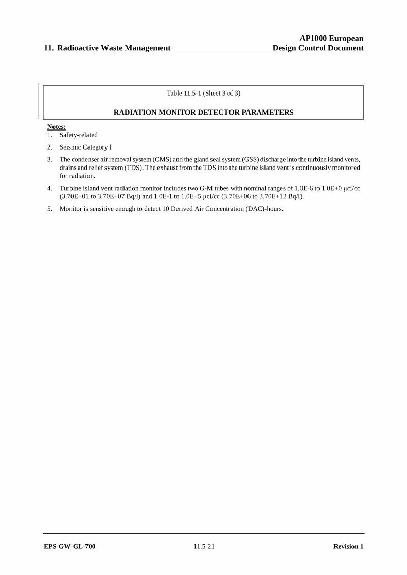
Table 11.5-1 (Sheet 3 of 3)
RADIATION MONITOR DETECTOR PARAMETERS
Notes: 1. Safety-related
2. Seismic Category I
3. The condenser air removal system (CMS) and the gland seal system (GSS) discharge into the turbine island vents, drains and relief system (TDS). The exhaust from the TDS into the turbine island vent is continuously monitored for radiation.
4. Turbine island vent radiation monitor includes two G-M tubes with nominal ranges of 1.0E-6 to 1.0E+0 µci/cc (3.70E+01 to 3.70E+07 Bq/l) and 1.0E-1 to 1.0E+5 µci/cc (3.70E+06 to 3.70E+12 Bq/l).
5. Monitor is sensitive enough to detect 10 Derived Air Concentration (DAC)-hours.

AP1000 European 11. Radioactive Waste Management Design Control Document
EPS-GW-GL-700 11.5-22 Revision 1
Table 11.5-2 (Sheet 1 of 2)
AREA RADIATION MONITOR DETECTOR PARAMETERS
Detector Type Service Nominal Range
PXS-JE-RE160 γ Containment High Range (Note 3) 1.0E-0 to 1.0E+7 R/hr (1.0E-02 to 1.0E+05 Sv/hr)
PXS-JE-RE161 γ Containment High Range (Note 3) 1.0E-0 to 1.0E+7 R/hr (1.0E-02 to 1.0E+05 Sv/hr)
PXS-JE-RE162 γ Containment High Range (Note 3) 1.0E-0 to 1.0E+7 R/hr (1.0E-02 to 1.0E+05 Sv/hr)
PXS-JE-RE163 γ Containment High Range (Note 3) 1.0E-0 to 1.0E+7 R/hr (1.0E-02 to 1.0E+05 Sv/hr)
RMS-JE-RE008 γ Primary Sampling Room 1.0E-1 to 1.0E+7 mR/hr (1.0E-03 to 1.0E+05 mSv/hr)
RMS-JE-RE009 γ Containment Area Personnel Hatch – Operating Deck – 135′-3″ (110.74 m) Elevation
1.0E-1 to 1.0E+4 mR/hr (1.0E-03 to 1.0E+02 mSv/hr) (Note 1)
RMS-JE-RE010 γ Main Control Room 1.0E-1 to 1.0E+4 mR/hr (1.0E-03 to 1.0E+02 mSv/hr)
RMS-JE-RE011 γ Chemistry Laboratory Area 1.0E-1 to 1.0E+4 mR/hr (1.0E-03 to 1.0E+02 mSv/hr)
RMS-JE-RE012 γ Fuel Handling Area 1.0E-1 to 1.0E+4 mR/hr (1.0E-03 to 1.0E+02 mSv/hr) (Note 2)
RMS-JE-RE013 γ Rail Car Bay/Filter Storage Area (Note 4)
1.0E-1 to 1.0E+4 mR/hr (1.0E-03 to 1.0E+02 mSv/hr)
RMS-JE-RE014A γ Liquid and Gaseous Radwaste Area 1 1.0E-1 to 1.0E+4 mR/hr (1.0E-03 to 1.0E+02 mSv/hr)
RMS-JE-RE014B γ Liquid and Gaseous Radwaste Area 2 1.0E-1 to 1.0E+4 mR/hr (1.0E-03 to 1.0E+02 mSv/hr)
RMS-JE-RE016 γ CSA Area 1.0E-1 to 1.0E+4 mR/hr (1.0E-03 to 1.0E+02 mSv/hr)
RMS-JE-RE017 γ Radwaste Bldg. Mobile Systems Facility (Note 4)
1.0E-1 to 1.0E+4 mR/hr (1.0E-03 to 1.0E+02 mSv/hr)
RMS-JE-RE018 γ Hot Machine Shop 1.0E-1 to 1.0E+4 mR/hr (1.0E-03 to 1.0E+02 mSv/hr)
RMS-JE-RE019 γ Annex Staging & Storage Area 1.0E-1 to 1.0E+4 mR.hr (1.0E-03 to 1.0E+02 mSv/hr)
RMS-JE-RE020 γ Fuel Handling Area 1.0E-1 to 1.0E+4 mR/hr (1.0E-03 to 1.0E+02 mSv/hr) (Note 2)
AP1000 European 11. Radioactive Waste Management Design Control Document
EPS-GW-GL-700 11.5-23 Revision 1
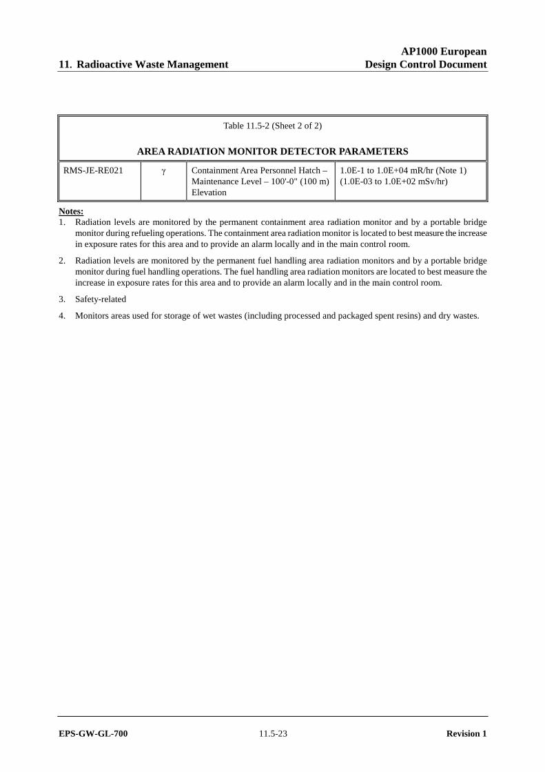
Table 11.5-2 (Sheet 2 of 2)
AREA RADIATION MONITOR DETECTOR PARAMETERS
RMS-JE-RE021 γ Containment Area Personnel Hatch – Maintenance Level – 100'-0" (100 m) Elevation
1.0E-1 to 1.0E+04 mR/hr (Note 1) (1.0E-03 to 1.0E+02 mSv/hr)
Notes: 1. Radiation levels are monitored by the permanent containment area radiation monitor and by a portable bridge
monitor during refueling operations. The containment area radiation monitor is located to best measure the increase in exposure rates for this area and to provide an alarm locally and in the main control room.
2. Radiation levels are monitored by the permanent fuel handling area radiation monitors and by a portable bridge monitor during fuel handling operations. The fuel handling area radiation monitors are located to best measure the increase in exposure rates for this area and to provide an alarm locally and in the main control room.
3. Safety-related
4. Monitors areas used for storage of wet wastes (including processed and packaged spent resins) and dry wastes.

AP1000 European 11. Radioactive Waste Management Design Control Document
EPS-GW-GL-700 11.5-24 Revision 1
Figure 11.5-1
Process In-Line Radiation Monitor

AP1000 European 11. Radioactive Waste Management Design Control Document
EPS-GW-GL-700 11.5-25 Revision 1
Figure 11.5-2
Safety-Related Containment High Range Radiation Monitor

AP1000 European 11. Radioactive Waste Management Design Control Document
EPS-GW-GL-700 11.5-26 Revision 1
Figure 11.5-3
Containment Atmosphere Radiation Monitor

AP1000 European 11. Radioactive Waste Management Design Control Document
EPS-GW-GL-700 11.5-27 Revision 1
Figure 11.5-4
Plant Vent Radiation Monitor

AP1000 European 11. Radioactive Waste Management Design Control Document
EPS-GW-GL-700 11.5-28 Revision 1
Figure 11.5-5
In-Line HVAC Duct Radiation Monitor

AP1000 European 11. Radioactive Waste Management Design Control Document
EPS-GW-GL-700 11.5-29 Revision 1
Figure 11.5-6
Safety-Related Main Control Room Supply Duct Radiation Monitor

AP1000 European 11. Radioactive Waste Management Design Control Document
EPS-GW-GL-700 11.5-30 Revision 1
Figure 11.5-7
Liquid Offline Radiation Monitor

AP1000 European 11. Radioactive Waste Management Design Control Document
EPS-GW-GL-700 11.5-31 Revision 1
Figure 11.5-8
Adjacent to Line Radiation Monitor

AP1000 European 11. Radioactive Waste Management Design Control Document
EPS-GW-GL-700 11.5-32 Revision 1
Figure 11.5-9
HVAC Duct Particulate Radiation Monitor