
“This telephone has too many shortcomings to be...
60
“This telephone has too many shortcomings to be seriously considered as a means of communication. The device is of no value to us.” Western Union internal memo, 1876
Transcript of “This telephone has too many shortcomings to be...

“This telephone has too many shortcomings to be seriously considered as a means of communication. The device is of no value to us.”
Western Union internal memo, 1876
chpt_02.fm Page 40 Thursday, May 1, 2003 9:55 AM

C
H
A
P
T
E
R
2
IPv6 Addressing
After reading this chapter, you will be able to describe the new IPv6 header format and the impact of IPv6 on User Datagram Protocol (UDP), Transport Control Protocol (TCP) data-grams, and the Maximum Transmission Unit (MTU). You will understand the addressing architecture of IPv6 with all kinds of IPv6 addresses scoped in the protocol. These addresses include link-local, site-local, aggregatable global unicast, loopback, unspecified, IPv4-compatible, multicast assigned, solicited-node multicast, and anycast. This chapter also presents IPv6 over Ethernet, multicast mapping over Ethernet, and EUI-64 format.
Throughout this chapter, you will see sample configurations using the Cisco IOS Software technology to acquire basic knowledge to configure and operate routers in an IPv6 environ-ment. Examples show you how to enable IPv6 and IPv6 forwarding on a router. Examples also show you how to configure IPv6 addresses on network interfaces under Cisco IOS Software technology.
Finally, with the configuration exercise in the case study, you can practice commands learned in this chapter by configuring, analyzing, and displaying IPv6 using the Cisco IOS Software technology.
IP Header
This section reviews the IPv4 header. It describes the fields and compares them to the fields in the IPv6 header.
IPv4 Header Format
IP packets are carried over link-layer technologies such as Ethernet (10 Mbps), Fast Ether-net (100 Mbps), Gigabit Ethernet (1000 Mbps), Frame Relay, and many others. Each link-layer technology family has its own link-layer frame that carries IP packets. As shown in Figure 2-1, an IP packet is carried between the frame header and frame trailer of a link-layer frame. An IP packet has two fundamental components:
•
IP header
—The IP header contains many fields that are used by routers to forward the packet from network to network to a final destination. Fields within the IP header identify the sender, receiver, and transport protocol and define many other parameters.
•
Payload
—Represents the information (data) to be delivered to the receiver by the sender.
chpt_02.fm Page 41 Thursday, May 1, 2003 9:55 AM

42
Chapter 2: IPv6 Addressing
Figure 2-1
IP Packet Carried by a Link-Layer Frame Contains a Header and a Payload
As shown in Figure 2-2, the basic IPv4 header contains 12 fields. As defined in RFC 791,
Internet Protocol DARPA Internet Program Specification,
each field of the IPv4 header has a specific use. This section summarizes the contents of the IPv4 header to help you understand the main differences between the IPv4 header and the new IPv6 header.
Figure 2-2
Fields in the IPv4 Header
Following are the IPv4 header fields:
•
Version (4-bit)
—The version of the IP (Internet Protocol) header. The current IP version used on the Internet is 4 (IPv4). This field contains the value 4.
•
Header Length (4-bit)
—The length in octets of the header size up to the Payload field.
•
Type of Service (TOS) (8-bit)
—Specifies the treatment of the datagram during its transmission through the routers. This field can also be interpreted as Differentiated Services Code Point (DSCP).
•
Total Length (16-bit)
—The size of the IP packet in octets, including the header and the payload. This field is 16-bit, which means that the maximum size of an IPv4 packet is 65,535 octets.
PayloadHeader
IP Packet
Frame
Header
Frame
Trailer
Link-Layer Frame
Options
(Variable)
Padding
(Variable)
Ver (4) Type of Service (8) Total Length (16)
Time to Live (8) Protocol Number (8)
Source IPv4 Address (32 Bit)
Destination IPv4 Address (32 Bit)
32 Bit
20
Octets
Payload
+ (When Necessary)
Hd Len (4)
Identification (16) Flags (3) Fragment Offset (13)
Header Checksum (16)
Variable
Length
chpt_02.fm Page 42 Thursday, May 1, 2003 9:55 AM

IP Header
43
•
Identification (16-bit), Flags (3-bit), and Fragment Offset (13-bit)
—Fields related to packet fragmentation by routers when the MTU along a path is smaller than the sender’s MTU. The MTU is the maximum size in octets of an IP packet that can be transmitted on a specific communication medium, such as Ethernet, Fast Ethernet, and so on. For Ethernet, the MTU is 1500 octets.
•
Time to Live (8-bit)
—This field is decremented each time the packet passes through an intermediary router. When this field contains the value 0, the packet is destroyed, and an Internet Control Message Protocol for IPv4 (ICMPv4) Type 11 error message (Time Exceeded) is sent to the source node.
•
Protocol Number (8-bit)
—Specifies the upper-layer protocol used in a packet’s payload, such as Transport Control Protocol (TCP), User Datagram Protocol (UDP), Internet Control Message Protocol (ICMP), or any others. Protocols supported are defined by the Internet Assigned Numbers Authority (IANA).
•
Header Checksum (16-bit)
—Represents the checksum of the IP header and is used for error checking. This field is verified and recomputed by each intermediary router along a path.
•
Source IPv4 Address (32-bit)
—The sender’s IPv4 address.
•
Destination IPv4 Address (32-bit)
—The receiver’s IPv4 address.
•
Options (variable)
—This optional field might appear in an IPv4 packet. The Options field is variable in size and increases the length of the header when used.
•
Padding (variable)
—Padding is used to ensure that the packet ends on a 32-bit boundary. It also increases the header’s size.
•
Payload (variable)
—The payload is not a field of the basic IPv4 header. Rather, it represents the data to be delivered to a destination address. The payload includes an upper-layer header.
NOTE
Protocol numbers are assigned by IANA. A complete list of all protocol numbers assigned by
IANA can be found at www.iana.org/assignments/protocol-numbers.
In IPv6, several fields of the IPv4 header are removed. In Figure 2-2, these fields are gray or black. The main reasons for these removals are as follows:
•
Header Length
—The basic IPv4 header is only 20 bytes long. However, the basic IPv6 header has a fixed length of 40 octets. The IPv4 header length indicates the packet’s total length, including the Options field. When present, the Options field increases the length of the IPv4 header. Instead of the Options field, IPv6 uses the Extension field. The Extension field is handled differently from how IPv4 handles the Options field.
chpt_02.fm Page 43 Thursday, May 1, 2003 9:55 AM

44
Chapter 2: IPv6 Addressing
•
Identification, Flags, and Fragment Offset
—Fragmentation is handled differently in IPv6. It is no longer done by intermediate routers in the networks, but by the source node that originates the packet. Removing the Fragmentation field removes costly CPU pro-cessing at intermediate routers. The path MTU discovery (PMTUD) mechanism, discussed later in this chapter, is recommended for every IPv6 node to avoid fragmentation.
•
Header Checksum
—Link-layer technologies (Layer 2) perform their own checksum and error control. The reliability of link-layer is now good and upper-layer protocols such TCP and UDP (Layer 4) have their own checksums. UDP checksum, which was optional in IPv4, is mandatory in IPv6. Therefore, the checksum at Layer 3 is redundant, so the Header Checksum field is unnecessary in IPv6 and suppresses the recomputation process each time a packet passes through a router.
•
Options and Padding
—The Options field is radically changed in IPv6. The options are now handled by extension headers (as discussed later in this chapter). The Padding field is also removed. The removal of Options and Padding headers simplifies the IP header. Thus, the basic IPv6 header has a fixed length of 40 octets, allowing less processing by routers along the delivery path compared to IPv4. The other fields in the IPv4 header—Version, Type of Service, Total Length, Time to Live, Protocol Number, Source IPv4 Address, and Destination IPv4 Address—either were not changed or were modified only slightly (as described in the next section).
Basic IPv6 Header Format
As defined in RFC 2460,
Internet Protocol, Version 6 (IPv6) Specification,
the basic IPv6 header contains eight fields, in comparison with 12 fields in IPv4 (without the Options and Padding fields), for a total length of 40 octets. Moreover, the basic IPv6 header might have one too many extension headers daisy-chained following the 40 octets. This section summarizes the fields of the basic IPv6 header.
The IPv6 protocol represents an upgrade of the IPv4 protocol. As shown in Figure 2-3, the Flow Label field and the extension headers with their variable length are new in IPv6. Here are the descriptions of the fields in the basic IPv6 header:
•
Version (4-bit)
—The IP version. This field contains the value 6 rather than the value 4 contained in an IPv4 packet.
•
Traffic Class (8-bit)
—This field and its functions are similar to the Type of Service field in IPv4. This field tags an IPv6 packet with a Differentiated Services Code Point (DSCP) that specifies how the packet should be handled.
•
Flow Label (20-bit)
—This field is used to tag a flow for IPv6 packets. This is new in the IPv6 protocol. The current IETF standard does not specify the details about how to manage and process the Flow Label.
chpt_02.fm Page 44 Thursday, May 1, 2003 9:55 AM

IP Header
45
NOTE
Refer to the IETF draft “IPv6 Flow Label Specification” (www.ietf.org/internet-drafts/draft-ietf-ipv6-flow-label-06.txt) for detailed information on the specification and the possible usage
of the Flow Label field with IPv6.
•
Payload Length (16-bit)
—This field represents the payload’s length. The payload is the remaining part of the packet following the IPv6 header.
•
Next Header (8-bit)
—As shown in Figure 2-4, this field defines the type of information following the basic IPv6 header. The type of information can be an upper-layer protocol such as TCP or UDP, or it can be one of the new optional extension headers. The Next Header field is similar to the Protocol Number field in IPv4. Supported protocols are defined by the IANA.
•
Hop Limit (8-bit)
—This field defines the maximum number of hops (intermediate routers) that the IP packet can pass through. Each hop decreases this value by 1. As in IPv4, when this field contains the value 0, the packet is destroyed and an Internet Control Message Protocol for IPv6 (ICMPv6) Type 3 message (Time Exceeded) is sent to the source node. See Chapter 3, “IPv6 in Depth,” for information about ICMPv6.
•
Source Address (128-bit)
—This field identifies the IPv6 source address of the sender.
•
Destination Address (128-bit)
—This field identifies the packet’s IPv6 destination address.
Figure 2-3
Fields Within the Basic IPv6 Header
Traffic Class (8) Flow Label (20)
Payload Length (16)
Source IPv6 Address (128 Bit)
Version (4)
Next Header (8) Hop Limit (8)
Destination IPv6 Address (128 Bit)
40
Octets
32 Bit
+
Extension Header InformationNext Header Variable
Length
Payload
chpt_02.fm Page 45 Thursday, May 1, 2003 9:55 AM

46
Chapter 2: IPv6 Addressing
Figure 2-4
Next Header Field Specifies the Type of Information Following the Basic IPv6 Header
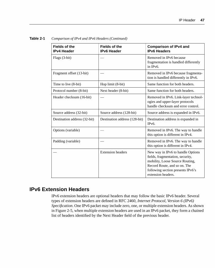
Table 2-1 compares IPv4 and IPv6 headers.
Table 2-1
Comparison of IPv4 and IPv6 Headers
Fields of the IPv4 Header
Fields of the IPv6 Header
Comparison of IPv4 and IPv6 Headers
Version (4-bit) Version (4-bit) Same function but the IPv6 header contains a new value.
Header length (4-bit) — Removed in IPv6. The basic IPv6 header always has 40 octets.
Type of service (8-bit) Traffic class (8-bit) Same function for both headers.
— Flow label (20-bit) New field added to tag a flow for IPv6 packets.
Total length (16-bit) Payload length (16-bit) Same function for both headers.
Identification (16-bit) — Removed in IPv6 because fragmenta-tion is handled differently in IPv6.
Traffic Class Flow Label
Payload Length
Source IPv6 Address (128 Bit)
Version
Next Header Hop Limit
Destination IPv6 Address (128 Bit)
40
Octets
Extension Header InformationNext Header Variable
Length
Payload
chpt_02.fm Page 46 Thursday, May 1, 2003 9:55 AM
IP Header
47
IPv6 Extension Headers
IPv6 extension headers are optional headers that may follow the basic IPv6 header. Several types of extension headers are defined in RFC 2460,
Internet Protocol, Version 6 (IPv6) Specification
. One IPv6 packet may include zero, one, or multiple extension headers. As shown in Figure 2-5, when multiple extension headers are used in an IPv6 packet, they form a chained list of headers identified by the Next Header field of the previous header.
Flags (3-bit) — Removed in IPv6 because fragmentation is handled differently in IPv6.
Fragment offset (13-bit) — Removed in IPv6 because fragmenta-tion is handled differently in IPv6.
Time to live (8-bit) Hop limit (8-bit) Same function for both headers.
Protocol number (8-bit) Next header (8-bit) Same function for both headers.
Header checksum (16-bit) — Removed in IPv6. Link-layer technol-ogies and upper-layer protocols handle checksum and error control.
Source address (32-bit) Source address (128-bit) Source address is expanded in IPv6.
Destination address (32-bit) Destination address (128-bit) Destination address is expanded in IPv6.
Options (variable) — Removed in IPv6. The way to handle this option is different in IPv4.
Padding (variable) — Removed in IPv6. The way to handle this option is different in IPv4.
— Extension headers New way in IPv6 to handle Options fields, fragmentation, security, mobility, Loose Source Routing, Record Route, and so on. The following section presents IPv6’s extension headers.
Table 2-1
Comparison of IPv4 and IPv6 Headers (Continued)
Fields of the IPv4 Header
Fields of the IPv6 Header
Comparison of IPv4 and IPv6 Headers
chpt_02.fm Page 47 Thursday, May 1, 2003 9:55 AM

48
Chapter 2: IPv6 Addressing
Figure 2-5
Multiple Extension Headers May Form a Chained List of Headers All Linked to the Next Header Field
For typical IPv6 applications, the last header of a chain is the upper-layer protocol carrying the packet’s payload. The upper-layer protocol may be TCP, UDP, or an ICMPv6 packet, for example.
Here are IPv6’s defined extension headers:
•
Hop-by-Hop Options header (protocol 0)
—This field is read and processed by every node and router along the delivery path. The Hop-by-Hop Options header is used for Jumbo-gram packets and the Router Alert. An example of applying the Hop-by-Hop Options header is Resource Reservation Protocol (RSVP) because each router needs to look at it.
NOTE
IPv6 can send packets greater than 65,535 octets, especially on a network with a very large MTU value. As defined in RFC 2675,
IPv6 Jumbograms,
these packets are called
Jumbograms
. IPv4 cannot send packets greater than 65,535 octets because the Total Length field is a 16-bit value. Basically, the IPv6 header has the same limitation of 65,535 octets related to the field Payload Length. However, by using a 32-bit field within the Hop-by-Hop Options header, a
Jumbogram packet may have a maximum length of 4,294,967,295 octets.
NOTE
When a source node sends an IPv6 packet to a destination node using extension headers, intermediate routers along the delivery path must not scan and process extension headers. However, as defined in RFC 2711,
IPv6 Router Alert Option,
the Router Alert feature within the Hop-by-Hop Options header may be used when a packet that is sent to a particular
destination requires special processing by intermediate routers along the delivery path.
Extension Header #1
Next Header
Extension Header #2
Next Header
Next Header
Payload
Basic IPv6 Header
IPv6
Packet
chpt_02.fm Page 48 Thursday, May 1, 2003 9:55 AM

IP Header
49
•
Destination Options header (protocol 60)
—This header carries optional information that is specifically targeted to a packet’s destination address. The Mobile IPv6 protocol specification, which is a draft status at IETF, proposes to use the Destination Options header to exchange registration messages between mobile nodes and the home agent. Mobile IP is a protocol allowing mobile nodes to keep permanent IP addresses even if they change point of attachment.
•
Routing header (protocol 43)
—This header can be used by an IPv6 source node to force a packet to pass through specific routers on the way to its destination. A list of intermedi-ary routers may be specified within the Routing header when the Routing Type field is set to 0. This function is similar to the Loose Source Routing option in IPv4.
Routing Header in Detail
Compared to IPv4, the way of handling Loose Source Routing is different in IPv6. As soon as the list of intermediary IPv6 routers is done, before sending the IPv6 packet, the source node executes the following operations in this order:
Step 1 Makes the first router of the intermediary routers list the destination address in the basic IPv6 header rather than the original IPv6 destination.
Step 2 Makes the original IPv6 destination the final destination of the intermediary list of routers.
Step 3 Decrements by 1 the Segments Left field of the Routing header as the packet travels along each router. This field acts as a pointer to contain the remaining number of router segments to the original destination.
Then, at each intermediary router of the list, the following steps occur:
(a) The intermediary router changes the destination address of the basic IPv6 header to target the next router on the intermediary list.
(b) The router decrements by 1 the Segments Left field of the Routing header.
(c) The router puts its own address to the intermediary list of routers in the Routing header just before the next router (the way to record route).
(d) If the router is the last of the intermediary routers list, it changes the IPv6 destination address of the basic IPv6 header to the final destination node, which is in fact the packet’s original destination.
The destination node, after having received the packet with the Routing header, can see the list of intermediary routers recorded in the Routing header. Then, the destination node can also send reply packets to the source node using a Routing header and can specify the same router list but in the inverse order.
chpt_02.fm Page 49 Thursday, May 1, 2003 9:55 AM

50 Chapter 2: IPv6 Addressing
As illustrated in Figure 2-6, source node A wants to deliver a packet to destination node B by forcing the packet to pass through a list of intermediary routers specified within a Routing header. Router R2 and then router R4 are identified in the list of intermediary routers to deliver the packet to destination node B. Node A first sends the packet to router R2. The packet uses router R2 as the destination address within the basic IPv6 header. The next address of the inter-mediary list of routers is router R4, and the last address of the list is destination node B. After receiving the packet, router R2 sends the packet to router R4. The packet uses router R4 as the destination address within the basic IPv6 header. The next address of the router’s intermediary list is now destination node B, which is the packet’s original destination node. Finally, after receiving the packet, router R4 sends its packet to destination node B through router R6 instead of router R7 (the shortest path to reach destination node B). Because router R6 is not on the list of intermediary routers, the packet is forwarded normally by router R4. The packet uses desti-nation node B as the destination address, and the Routing header contains the list of intermedi-ary routers (R2, R6) that belong to this path.
Figure 2-6 Packet Passing Through the List of Intermediary Routers Along the Delivery Path
Only a few applications exist for using the Routing header in IPv6. Mobile IPv6 is an example of a protocol that uses the Routing header when a node is away from its home network. The Routing header provides efficiency to the protocol compared to Mobile IPv4. Chapter 3 presents an overview of the Mobile IPv6 protocol.
R1
SourceNode
DestinationNode
R2
R3 R4
R5 R6 R7
Path
Source: Node ADestination: R2Next : R4Last: Node B
Source: Node ADestination: Node BRouters List: R2,R4
Source: Node ADestination: R4Next : Node B
Source: Node ADestination: Node BList: R2,R4
A
B
chpt_02.fm Page 50 Thursday, May 1, 2003 9:55 AM

IP Header 51
See RFC 2460, Internet Protocol, Version 6 (IPv6) Specification, for additional information about the Routing header specification and fields.
Now that you have read about the Routing header in detail, the following list presents other extension headers defined in the IPv6 protocol:
• Fragment header (protocol 44)—In IPv6, the PMTUD mechanism is recommended to all IPv6 nodes. PMTUD is discussed in detail in Chapter 3. When an IPv6 node does not support PMTUD and it must send a packet larger than the greatest MTU along the delivery path, the Fragment header is used. When this happens, the node fragments the packets and sends each fragment using Fragment headers. Then the destination node reassembles the original packet by concatenating all the fragments.
NOTE In IPv6, fragmentation is undesirable. When necessary, fragmentation is performed by source nodes, not by routers along a packet’s delivery path. In IPv4, fragmentation is done at the originating nodes as well as at the intermediate routers.
• Authentication header (protocol 51)—This header is used in IPSec to provide authenti-cation, data integrity, and replay protection. It also ensures protection of some fields of the basic IPv6 header. This header is identical in both IPv4 and IPv6. It is well-known as the IPSec authentication header (AH).
• Encapsulating Security Payload header (protocol 50)—This header is also used in IPSec to provide authentication, data integrity, replay protection, and confidentiality of the IPv6 packet. Similar to the authentication header, this header is identical in both IPv4 and IPv6. It is well-known as IPSec Encapsulating Security Payload (ESP).
Multiple Extension HeadersWhen multiple extension headers are used in an IPv6 packet, their order must be as follows:
1 Basic IPv6 header
2 Hop-by-Hop Options
3 Destination Options (if the Routing header is used)
4 Routing
5 Fragment
6 Authentication
7 Encapsulating Security Payload
8 Destination Options
9 Upper-layer (TCP, UDP, ICMPv6, ...)
chpt_02.fm Page 51 Thursday, May 1, 2003 9:55 AM

52 Chapter 2: IPv6 Addressing
Packets including several extension headers must be processed strictly by the destination nodes in the order they appear in the IPv6 packet. The node that receives packets must not, for example, scan through a packet looking for a particular kind of extension header and process that header before processing all the preceding ones.
User Datagram Protocol (UDP) and IPv6UDP (protocol 17) is considered an upper-layer protocol by IPv4 and IPv6. UDP has not been changed for IPv6 and continues to run on top of both IPv6 and IPv4 headers. However, as shown in Figure 2-7, the Checksum field in the UDP packet is mandatory with IPv6. This field was optional in IPv4. Therefore, the UDP Checksum field must be computed by IPv6 source nodes before an IPv6 packet is sent.
Figure 2-7 UDP Checksum Field in the UDP Packet Is Mandatory with IPv6
The UDP checksum is necessary because the Checksum field of the IPv4 header was removed. This field was used to verify the integrity of the inner packet.
Transport Control Protocol (TCP) and IPv6TCP (protocol 6) is also considered an upper-layer protocol by IPv4 and IPv6. The Checksum field within the TCP header is mandatory in IPv4. Because TCP is a very complex protocol, no change was proposed to this protocol for IPv6. It was decided during the engineering of IPv6 to continue to run TCP and UDP protocols on top of IPv6 without structural modifications.
Maximum Transmission Unit (MTU) for IPv6In IPv4, a link’s minimum MTU length is 68 octets. Every Internet module in IPv4 must be able to forward IPv4 packets of 68 bytes without further fragmentation. The maximum length of an IPv4 header is 60 octets. The minimum fragment size is eight octets.
40Octets
Basic IPv6
Header
UDPPacket
Source Port
UDP Checksum
Destination Port
Length
UDP Data Portion
chpt_02.fm Page 52 Thursday, May 1, 2003 9:55 AM
Addressing 53
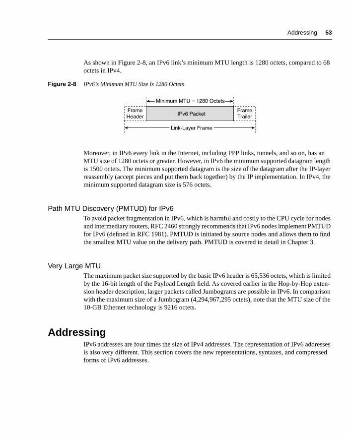
As shown in Figure 2-8, an IPv6 link’s minimum MTU length is 1280 octets, compared to 68 octets in IPv4.
Figure 2-8 IPv6’s Minimum MTU Size Is 1280 Octets
Moreover, in IPv6 every link in the Internet, including PPP links, tunnels, and so on, has an MTU size of 1280 octets or greater. However, in IPv6 the minimum supported datagram length is 1500 octets. The minimum supported datagram is the size of the datagram after the IP-layer reassembly (accept pieces and put them back together) by the IP implementation. In IPv4, the minimum supported datagram size is 576 octets.
Path MTU Discovery (PMTUD) for IPv6To avoid packet fragmentation in IPv6, which is harmful and costly to the CPU cycle for nodes and intermediary routers, RFC 2460 strongly recommends that IPv6 nodes implement PMTUD for IPv6 (defined in RFC 1981). PMTUD is initiated by source nodes and allows them to find the smallest MTU value on the delivery path. PMTUD is covered in detail in Chapter 3.
Very Large MTUThe maximum packet size supported by the basic IPv6 header is 65,536 octets, which is limited by the 16-bit length of the Payload Length field. As covered earlier in the Hop-by-Hop exten-sion header description, larger packets called Jumbograms are possible in IPv6. In comparison with the maximum size of a Jumbogram (4,294,967,295 octets), note that the MTU size of the 10-GB Ethernet technology is 9216 octets.
AddressingIPv6 addresses are four times the size of IPv4 addresses. The representation of IPv6 addresses is also very different. This section covers the new representations, syntaxes, and compressed forms of IPv6 addresses.
IPv6 Packet
Minimum MTU = 1280 Octets
Frame
Header
Frame
Trailer
Link-Layer Frame
chpt_02.fm Page 53 Thursday, May 1, 2003 9:55 AM

54 Chapter 2: IPv6 Addressing
Representation of IPv6 AddressesAs defined in RFC 2373, IP Version 6 Addressing Architecture, three formats represent IPv6 addresses. The preferred format is the longest method. It represents all 32 hexadecimal charac-ters that form an IPv6 address. The preferred format may also be seen as the representation that matches a computer’s “thinking.”
The next method is the compressed representation of an IPv6 address. To simplify the typing of IPv6 addresses by humans, it is possible to compress the address when zero values are present in the IPv6 address. This means that preferred and compressed formats are different represen-tations of the same IPv6 addresses, a new concept in comparison with IPv4.
Finally, the third method to represent an address is related to transition mechanisms where an IPv4 address is embedded in an IPv6 address. This last representation is less important than the preferred and the compressed format, because it is useful only if you’re using specific transition mechanisms such as automatic IPv4-compatible tunnels and dynamic Network Address Trans-lation Protocol Translation (NAT-PT). Automatic IPv4-compatible tunnels and dynamic NAT-PT mechanisms are discussed in detail in Chapter 5, “IPv6 Integration and Coexistence Strategies.”
Preferred IPv6 Address RepresentationAs shown in Figure 2-9, the preferred representation, also known as the complete form of an IPv6 address, has a series of eight 16-bit hexadecimal fields separated by colons (:). Each 16-bit field is textually represented by four hexadecimal characters, meaning that the value of each 16-bit field may have hexadecimal values 0x0000 through 0xFFFF. Alphanumeric characters used in hexadecimal are case-insensitive.
Figure 2-9 IPv6 Addresses Have Eight Fields of 16-Bit Hexadecimal Values Separated by Colons
The preferred format is the longest representation of an IPv6 address. A total of 32 hexadecimal characters may be represented in this preferred form (eight fields of four hexadecimal charac-ters). In comparison, an IPv4 address has four 8-bit decimal fields separated by dots (.) for a possible total of 12 decimal characters.
0000
Thru
FFFF
0000
Thru
FFFF
0000
Thru
FFFF
0000
Thru
FFFFÉÉ.
16 Bit
X X X X X X X X
16 Bit 16 Bit 16 Bit16 Bit 16 Bit 16 Bit 16 Bit
chpt_02.fm Page 54 Thursday, May 1, 2003 9:55 AM

Addressing 55
Table 2-2 shows examples of IPv6 addresses in the preferred representation.
Compressed RepresentationIn IPv6, it is common to use addresses that contain long strings of 0s. To make writing addresses containing 0 bits easier for humans, a special syntax compresses consecutive 0 values in two situations—successive 16-bit fields made of 0s and leading 0s in 16-bit fields of an IPv6 address.
Successive 16-Bit Fields Made up of 0sTo simplify the length of an IPv6 address when one to multiple successive 16-bit fields of 0 characters are present, it is legal to represent these fields of 0s as :: (a double colon). However, only one :: is permitted in an IPv6 address. This method makes many IPv6 addresses very small. The compressed representation of an IPv6 address also means that the same address can have several representations.
NOTE When the :: is present in an IPv6 address, an address parser can identify the number of missing 0s. Then, the parser fills 0 characters between the two parts of the address until the 128-bit address is complete. If more than one :: is present in a compressed IPv6 address, there is no way for the parser to identify the size of each field of 0s. Therefore, only one :: is permitted per IPv6 address.
Table 2-3 presents examples of IPv6 addresses in the preferred format that have been com-pressed because they have one or more successive 16-bit fields of 0 characters. Bold characters in the preferred format addresses represent values to be removed to compress the addresses.
Table 2-2 Examples of IPv6 Addresses in the Preferred Format
Preferred Format of IPv6 Addresses
0000:0000:0000:0000:0000:0000:0000:0000
0000:0000:0000:0000:0000:0000:0000:0001
2001:0410:0000:1234:FB00:1400:5000:45FF
3ffe:0000:0000:0000:1010:2a2a:0000:0001
3FFE:0B00:0C18:0001:0000:1234:AB34:0002
FE80:0000:0000:0000:0000:0000:0000:0009
FFFF:FFFF:FFFF:FFFF:FFFF:FFFF:FFFF:FFFF
chpt_02.fm Page 55 Thursday, May 1, 2003 9:55 AM

56 Chapter 2: IPv6 Addressing
The address FFFF:FFFF:FFFF:FFFF:FFFF:FFFF:FFFF:FFFF is an example of an address in which all bits are set to 1. Therefore, this address cannot be compressed. Compressed form using the :: is available only when multiple successive 16-bit fields of 0 characters are present.
Table 2-4 presents illegal examples of compressed addresses. The compressed addresses represented use the :: more than once, which is an illegal IPv6 compressed address representation.
Leading 0s in 16-Bit Fields of an IPv6 AddressThe second method to compress addresses is applicable to each 16-bit hexadecimal field of an IPv6 address when one or more leading 0s are present. Leading 0s of each field can simply be removed to simplify the length of an IPv6 address. However, if every hexadecimal character of a 16-bit field is set to 0, at least one 0 character must be kept. Table 2-5 shows examples of addresses compressed when leading 0s are present. In these examples, all leading 0s of each 16-bit field are removed and all the following values are kept. Bold characters in the preferred format addresses represent values to be removed to compress the addresses.
Combining Both Compression MethodsCompression of successive 16-bit fields made of 0 characters and compression of leading 0 characters within 16-bit fields can be mixed to simplify the length of IPv6 addresses. Table 2-6 presents examples in which both compression methods are applied. Bold characters in the preferred format addresses represent values to be removed to compress the addresses.
Table 2-3 Examples of IPv6 Addresses in the Preferred Format That Are Formatted in the Compressed Format
Preferred Format Compressed Format Using ::
0000:0000:0000:0000:0000:0000:0000:0000 ::
0000:0000:0000:0000:0000:0000:0000:0001 ::0001
2001:0410:0000:1234:FB00:1400:5000:45FF 2001:0410::1234:FB00:1400:5000:45FF
3ffe:0000:0000:0000:1010:2a2a:0000:0001 3ffe::1010:2a2a:0000:0001
3FFE:0B00:0C18:0001:0000:1234:AB34:0002 3FFE:0B00:0C18:0001::1234:AB34:0002
FE80:0000:0000:0000:0000:0000:0000:0009 FE80::0009
FFFF:FFFF:FFFF:FFFF:FFFF:FFFF:FFFF:FFFF FFFF:FFFF:FFFF:FFFF:FFFF:FFFF:FFFF:FFFF
Table 2-4 Examples of Illegal IPv6 Compressed Address Representations
Preferred Format Compressed Format Using ::
0000:0000:AAAA:0000:0000:0000:0000:0001 ::AAAA::0001
3ffe:0000:0000:0000:1010:2a2a:0000:0001 3ffe::1010:2a2a::0001
chpt_02.fm Page 56 Thursday, May 1, 2003 9:55 AM

Addressing 57
IPv6 Address with an Embedded IPv4 AddressThe third representation of an IPv6 address is to use an embedded IPv4 address within the IPv6 address.
The first part of the IPv6 address uses the hexadecimal representation, and the IPv4 address part is in decimal format. This is a specific representation of an IPv6 address used by transition mechanisms.
NOTE The low-order 32-bit of the address may also be represented in hexadecimal on the implemen-tation supporting the automatic IPv4-compatible tunnel mechanism. Thus, the decimal values are converted into hex.
Table 2-5 Examples of IPv6 Addresses in Which Leading 0s of 16-Bit Fields Are Removed to Compress the Address
Preferred Format Compressed Format
0000:0000:0000:0000:0000:0000:0000:0000 0:0:0:0:0:0:0:0
0000:0000:0000:0000:0000:0000:0000:0001 0:0:0:0:0:0:0:1
2001:0410:0000:1234:FB00:1400:5000:45FF 2001:410:0:1234:FB00:1400:5000:45FF
3ffe:0000:0000:0000:1010:2a2a:0000:0001 3ffe:0:0:0:1010:2a2a:0:1
3FFE:0B00:0C18:0001:0000:1234:AB34:0002 3FFE:B00:C18:1:0:1234:AB34:2
FE80:0000:0000:0000:0000:0000:0000:0009 FE80:0:0:0:0:0:0:9
FFFF:FFFF:FFFF:FFFF:FFFF:FFFF:FFFF:FFFF FFFF:FFFF:FFFF:FFFF:FFFF:FFFF:FFFF:FFFF
Table 2-6 Examples of IPv6 Addresses Formatted in the Compressed Representation
Preferred Format Compressed Format
0000:0000:0000:0000:0000:0000:0000:0000 ::
0000:0000:0000:0000:0000:0000:0000:0001 ::1
2001:0410:0000:1234:FB00:1400:5000:45FF 2001:410::1234:FB00:1400:5000:45FF
3ffe:0000:0000:0000:1010:2a2a:0000:0001 3ffe::1010:2a2a:0:1
3FFE:0B00:0C18:0001:0000:1234:AB34:0002 3FFE:B00:C18:1::1234:AB34:2
FE80:0000:0000:0000:0000:0000:0000:0009 FE80::9
chpt_02.fm Page 57 Thursday, May 1, 2003 9:55 AM

58 Chapter 2: IPv6 Addressing
NOTE As mentioned at the beginning of this section, this form of IPv6 address is used by only two transition mechanisms. The transition mechanisms using this format are supported in the Cisco IOS Software technology, but the automatic IPv4-compatible tunnel mechanism is being deprecated in favor of more-efficient mechanisms. However, the transition mechanism called dynamic NAT-PT still embeds an IPv4 address within an IPv6 address for its operation. Thus, it uses this form of address.
Figure 2-10 shows the format of an IPv6 address using an embedded IPv4 address. This kind of address is made up of six high-order fields of 16-bit hexadecimal values, represented by X characters, followed by four low-order fields of 8-bit decimal values (IPv4 address), represented by d characters (for a total of 32 bits).
Figure 2-10 IPv6 Address with an Embedded IPv4 Address
Two kinds of IPv6 addresses have an embedded IPv4 address:
• IPv4-compatible IPv6 address—Used to establish an automatic tunnel to carry IPv6 packets over IPv4 networks. This address is related to a transition mechanism of the IPv6 protocol.
• IPv4-mapped IPv6 address—Used only on the local scope of nodes having both IPv4 and IPv6 stacks. Nodes use IPv4-mapped IPv6 addresses internally only. These addresses are never known outside the node itself and should not go on the wire as IPv6 addresses.
Although they both use the same address representation of an IPv4 address embedded in an IPv6 address, a different IPv6 prefix is defined for each kind of embedded IPv4 address. The IPv6 prefix for the IPv4-compatible IPv6 address is represented by the high-order 96-bit set to 0 followed by the 32-bit of the IPv4 address. The prefix for the IPv4-mapped IPv6 address is represented by the high-order 80-bit set to 0, then the next 16-bit set to 1, and finally followed by the 32-bit of the IPv4 address of the local node. The next section presents in detail the format of the IPv6 address with an embedded an IPv4 address.
0000
Thru
FFFF
0
Thru
255
16 Bit
X X X X X X d d d d
32 Bit
chpt_02.fm Page 58 Thursday, May 1, 2003 9:55 AM

Addressing 59
Table 2-7 shows examples of each kind of IPv4 address embedded in IPv6 addresses and also demonstrates that both addresses can be represented in compressed format. The first address presented is the IPv4-compatible IPv6 address and the second is an IPv4-mapped IPv6 address. Bold characters in the preferred format addresses represent values to be removed to compress the addresses.
NOTE Although the dynamic NAT-PT mechanism is based on the IPv4-compatible IPv6 address format, it does not use the IPv6 prefix presented here. Refer to Chapter 5 for more details about the prefix used by the dynamic NAT-PT mechanism.
IPv6 Address Representation for URLIn Uniform Resource Locator (URL) format, the colon (:) character is already defined to specify an optional port number. Here are examples of URLs using the colon character to specify a port number:
www.example.net:8080/index.html
https://www.example.com:8443/abc.html
In IPv6, the URL parser of Internet browsers must be able to differentiate between the colon of a port number and the colon in an IPv6 address. However, this is impossible because the compressed representation of an IPv6 address may include the double colon anywhere in the IPv6 address.
Therefore, to identify the IPv6 address while still keeping the colon character for URL format (port number), the IPv6 address must be enclosed in brackets, as defined in RFC 2732, Format for Literal IPv6 Addresses in URL’s. Then, after the brackets, the port number may be added, followed by the directory and filename. Here are examples of URLs with IPv6 addresses between brackets:
[3ffe:b80:c18:1::50]:8080/index.html
https://[2001:410:0:1:250:fcee:e450:33ab]:8443/abc.html
Table 2-7 Examples of IPv4-Compatible IPv6 Addresses and IPv4-Mapped IPv6 Addresses
Preferred Format Compressed Format
0000:0000:0000:0000:0000:0000:206.123.31.2 0:0:0:0:0:0:206.123.31.2 or ::206.123.31.2
0000:0000:0000:0000:0000:0000:ce7b:1f01 0:0:0:0:0:0:ce7b:1f01 or ::ce7b:1f01
0000:0000:0000:0000:0000:FFFF:206.123.31.2 0:0:0:0:0:FFFF:206.123.31.2 or ::FFFF:206.123.31.2
0000:0000:0000:0000:0000:FFFF:ce7b:1f01 0:0:0:0:0:FFFF:ce7b:1f01 or ::FFFF:ce7b:1f01
chpt_02.fm Page 59 Thursday, May 1, 2003 9:55 AM

60 Chapter 2: IPv6 Addressing
However, using IPv6 addresses inside brackets should normally be used for diagnostic purposes only or when the naming service (DNS) is unavailable. Because IPv6 addresses are longer than IPv4 addresses, users tend to use the DNS and the fully qualified domain name (FQDN) format instead of the IPv6 address in hexadecimal representation.
IPv6 and SubnettingIn IPv4, there are two ways to represent a network prefix:
• Decimal representation—A network mask is specified in d.d.d.d format. The network mask value represents the number of consecutive bits in binary that are set to 1.
• Classless interdomain routing (CIDR) notation—The network prefix mask may also be specified with a decimal number representing the number of consecutive bits in binary set to 1. The slash character is used between the prefix and the network mask value.
Both representations mean the same number of network mask bits for nodes. For example, the network prefix 192.168.1.0 with the network mask value of 255.255.255.0 is the same as 192.168.1.0/24 in CIDR notation. The range of IP addresses available for nodes in this network varies from 192.168.1.1 to 192.168.1.254.
In IPv6, the network mask representation using the long form, such as d.d.d.d, is gone because of the new length of the IPv6 address. The only acceptable form to represent a network mask in IPv6 is CIDR notation. Although IPv6 addresses are in hexadecimal format, the network mask value is still a decimal value. Table 2-8 shows examples of IPv6 addresses and network prefixes using the network value in CIDR notation.
For both IPv4 and IPv6, the number of bits set to 1 in the network mask defines the length of the network prefix; the remaining part is for node addressing. This information is fundamental to IP. It tells each node when packets must be sent to the default router or to a specific node on the same link-layer subnet.
Another difference in IPv6 is the absence of reserved addresses in a network prefix range. In IPv4, the first and last addresses of the prefix range are reserved addresses. A range’s first address is the network address and the last one is the broadcast address. This means that the
Table 2-8 Examples of IPv6 Prefixes with Network Masks
IPv6 Prefix Description
2001:410:0:1:0:0:0:45FF/128 Represents a subnet with only one IPv6 address.
2001:410:0:1::/64 Network prefix 2001:410:0:1::/64 can handle 264 nodes. This is the default prefix length for a subnet.
2001:410:0::/48 Network prefix 2001:410:0::/48 can handle 216 network prefixes of 64-bit. This is the default prefix length for a site.
chpt_02.fm Page 60 Thursday, May 1, 2003 9:55 AM

Addressing 61
total number of IPv4 addresses available in a range equals n2–2, where n is the number of bits for the host addressing. For example, with the network prefix 192.168.1.0/24, addresses 192.168.1.0 and 192.168.1.255 must not be assigned to nodes because they are reserved. In IPv4, it is also common to use different network mask values within a site. One subnet can use a network mask value, and the next subnet may use a different value.
IPv6 has no broadcast or network reserved addresses. Moreover, the number of bits for node addressing within a site prefix (48-bit) in IPv6 is so large that it is not necessary to make an addressing plan for a site using different network mask values. Therefore, network mask calculation for each subnet and the use of Variable-Length Subnet Masks (VLSMs) are not required. In IPv6, the subnetting allocation is much simpler than in IPv4.
IPv6 Address TypesIndependent of representation and subnetting, different kinds of addresses are defined for IPv6, as described in RFC 2373, IP Version 6 Addressing Architecture. This section presents the types of IPv6 addresses defined in the protocol. In IPv6, addresses are assigned to network interfaces, not to nodes. Moreover, each interface owns and uses multiple IPv6 addresses simultaneously.
As shown in Figure 2-11, the three types of addresses are unicast, anycast, and multicast. Under the scope of each kind of address are one or more types of addresses. Unicast has link-local, site-local, aggregatable global, loopback, unspecified, and IPv4-compatible addresses. Anycast has aggregatable global, site-local, and link-local. Multicast has assigned and solicited-node. Specific scopes of IPv6’s 128-bit addressing scheme are already assigned to each type of address.
Figure 2-11 Types of Addresses in the IPv6 Addressing Architecture
IPv6 Addressing
UnicastMulticast Anycast
Assigned Solicited-Node Aggregatable
Global
Unspecified
LoopbackAggregatable
Global
IPv4
CompatibleLink-Local Site-Local
FE80::/10 FEC0::/10::/128
::1/128
0:0:0:0:0:0::/962001::/16
2002::/16
3FFE::/16
2001::/16
2002::/16
3FFE::/16
FF00::/8 FF02::1:FF00:0000/104
Link-Local
FE80::/10
Site-Local
FEC0::/10
chpt_02.fm Page 61 Thursday, May 1, 2003 9:55 AM

62 Chapter 2: IPv6 Addressing
Link-Local AddressIPv6 introduces scoped unicast addresses, which can be used only in a restricted context. The unicast link-local address is scoped and is used only between nodes connected on the same local link. The link-local address is used by several IPv6 mechanisms, such as Neighbor Discovery Protocol (NDP), described in detail in Chapter 3.
When an IPv6 stack is enabled on a node, one link-local address is automatically assigned to each interface of the node at boot time. As shown in Figure 2-12, the IPv6 link-local prefix FE80::/10 is used and the interface identifier in Extended Unique Identifier 64 (EUI-64) format is appended as the address’s low-order 64-bit. Bits 11 through 64 are set to 0 (54-bit). Link-local addresses are only for local-link scope and must never be routed between subnets within a site.
Figure 2-12 Link-Local Address
NOTE The IEEE defined an extended unique identifier based on 64-bit—EUI-64. EUI-64 format is a combination of the public 24-bit manufacturer ID assigned by the IEEE and a 40-bit value assigned by the manufacturer to its products. EUI-64 is related to the interface link-layer address. This chapter provides detailed information about the conversion of a link-layer address into EUI-64 format.
Because the low-order 64-bit of the link-local address is the interface identifier itself, the length of the link-local prefix is based on a 64-bit length (/64).
As shown in Table 2-9, the link-local address is represented by the IPv6 prefix FE80:0000:0000:0000:0000:0000:0000:0000/10 in the preferred format and by FE80::/10 in the compressed representation.
128 Bit
Interface Identifier
64 Bit
EUI-64
FE80::/10
10 Bit
0
54 Bit
chpt_02.fm Page 62 Thursday, May 1, 2003 9:55 AM

Addressing 63
In IPv6, a node having an aggregatable global unicast address on a local link uses the link-local address of its default IPv6 router rather than the router’s aggregatable global unicast address. If network renumbering must occur, meaning that the unicast aggregatable global prefix is changed to a new one, the default router can always be reached using the link-local address. Link-local addresses of nodes and routers do not change during network renumbering. Chapter 3 presents an example of prefix renumbering on a local link.
Site-Local AddressA site-local address is another unicast scoped address to be used only within a site. Site-local addresses are not enabled by default on nodes like link-local addresses, meaning that they must be assigned.
A site-local address is similar to private address spaces in IPv4, such as 10.0.0.0/8, 172.16.0.0/12, and 192.168.0.0/16, as defined in RFC 1918, Address Allocation for Private Internets. Site-local addresses may be used by any organization that has not received aggregatable global uni-cast IPv6 spaces from a provider. A site-local prefix and address may be assigned to any nodes and routers within a site. However, site-local addresses must never be routed on the global IPv6 Internet.
NOTE Although site-local addresses are similar to the private addressing in IPv4, Network Address Translation (NAT) with IPv6 is undesirable between IPv6-only networks. Huge numbers of IPv6 addresses are available within the IPv6 address space to preserve the end-to-end model of the IP protocol.
As shown in Figure 2-13, the site-local address consists of the prefix FEC0::/10, a 54-bit field called Subnet-ID, and an interface identifier in EUI-64 format used as the low-order 64-bit.
Table 2-9 Link-Local Address Representations
Representation Value
Preferred format FE80:0000:0000:0000:0000:0000:0000:0000/10
Compressed format1 FE80:0:0:0:0:0:0:0:0/10
Compressed format FE80::/10
Binary format High-order 10-bit is set to 1111 1110 10
1 This is an intermediary compressed representation of the same address. This address is valid, but the shortened format of an IPv6 address should be used.
chpt_02.fm Page 63 Thursday, May 1, 2003 9:55 AM

64 Chapter 2: IPv6 Addressing
Figure 2-13 Site-Local Address
The 54-bit Subnet-ID is available for site subnetting. This field allows a site to create up to 254 different IPv6 subnets (/64 prefix). Each subnet can use a different IPv6 prefix.
NOTE The old Subnet-ID length for site-local addresses was based on 16-bit, allowing a site to create up to 65,535 different IPv6 subnets.
For example, a site with ten subnets may assign site-local prefixes such as the following:
• Subnet 1—FEC0:0:0:0001::/64
• Subnet 2—FEC0:0:0:0002::/64
• Subnet 3—FEC0:0:0:0003::/64
• Subnet 4—FEC0:0:0:0004::/64
• Subnet 5—FEC0:0:0:0005::/64
• Subnet 6—FEC0:0:0:0006::/64
• Subnet 7—FEC0:0:0:0007::/64
• Subnet 8—FEC0:0:0:0008::/64
• Subnet 9—FEC0:0:0:0009::/64
• Subnet 10—FEC0:0:0:000A::/64
As shown in Table 2-10, the site-local address is represented by the IPv6 prefix FEC0:0000:0000:0000:0000:0000:0000:0000/10 in the preferred format and by FEC0::/10 in the compressed representation.
128 Bit
Interface Identifier
64 Bit
EUI-64
FEC0::/10
10 Bit
Subnet-ID
54 Bit
chpt_02.fm Page 64 Thursday, May 1, 2003 9:55 AM

Addressing 65
Site-local addresses are designed for devices that will never communicate with the global IPv6 Internet. Site-local addresses may have the following uses within a site:
• Printers
• Intranet servers
• Network switches, bridges, gateways, wireless access points, and so on
• Any servers and routers that must only be reached internally for management purposes
For now, site-local addresses are recommended to organizations that have plans to deploy the IPv6 protocol on their networks before getting aggregatable global unicast IPv6 spaces from providers. Site-local addressing is also recommended for experimental scenarios of network renumbering.
It is important to note that an IPv6 node may have several unicast IPv6 addresses, so site-local addresses can be used at the same time as aggregatable global unicast addresses. In this case, DNS is the tie-breaker. Moreover, it is expected that the site will use the same subnet ID for the site-local and aggregatable global unicast prefixes.
Aggregatable Global Unicast AddressAggregatable global unicast addresses are IPv6 addresses used for the generic IPv6 traffic on the IPv6 Internet. Aggregatable global unicast addresses are similar to the unicast addresses used to communicate across the IPv4 Internet.
Aggregatable global unicast addresses represent the most important part of the IPv6 addressing architecture. The structure of aggregatable global unicast enables a strict aggregation of routing prefixes to limit the size of the global Internet routing table.
Table 2-10 Site-Local Address Representations
Representation Value
Preferred format FEC0:0000:0000:0000:0000:0000:0000:0000/10
Compressed format1 FEC0:0:0:0:0:0:0:0/10
Compressed format FEC0::/10
Binary format High-order 10-bit is set to 1111 1110 11
1 This is an intermediary compressed representation of the same address. This address is valid, but the shortened format of an IPv6 address should be used.
chpt_02.fm Page 65 Thursday, May 1, 2003 9:55 AM

66 Chapter 2: IPv6 Addressing
Each aggregatable global unicast IPv6 address has three parts:
• Prefix received from a provider—The prefix assigned to an organization (leaf site) by a provider should be at least a /48 prefix, as recommended in RFC 3177, IAB/IESG Recommendations on IPv6 Address Allocations to Sites. The /48 prefix represents the high-order 48-bit of the network prefix. Moreover, the prefix assigned to the organization is part of the provider’s prefix.
• Site—With one /48 prefix allocated to an organization by a provider, it is possible for that organization to enable up to 65,535 subnets (assignment of 64-bit’s prefix to subnets). The organization can use bits 49 to 64 (16-bit) of the prefix received for subnetting.
• Host—The host part uses each node’s interface identifier. This part of the IPv6 address, which represents the address’s low-order 64-bit, is called the interface ID.
As shown in Figure 2-14, the prefix 2001:0410:0110::/48 is assigned by a provider to an orga-nization. Then, within this organization, the prefix 2001:0410:0110:0002::/64 is enabled on a network subnet. Finally, a node on this subnet owns the IPv6 address 2001:0410:0110:0002:0200:CBCF:1234:4402.
Figure 2-14 Aggregatable Global Unicast Address
This is a simple example of an aggregatable global unicast prefix assigned to a leaf site by a provider. Chapter 7, “Connecting to the IPv6 Internet,” provides detailed information about aggregatable global unicast assignments between multiple sites, providers, and leaf sites.
IANA Assignments of Aggregatable Global Unicast PrefixesThe IANA assigned one IPv6 address prefix range in the whole IPv6 addressing space for aggregatable global unicast addresses. As shown in Table 2-11, this aggregatable global unicast address space is characterized by the IPv6 prefix 2000::/3.
128 Bit
64 Bit16 Bit
HostProvider Site
48 Bit
0200:CBCF:1234:44022001:0410:0110: 0002:
chpt_02.fm Page 66 Thursday, May 1, 2003 9:55 AM

Addressing 67
From the 2000::/3 prefix, three smaller prefixes (/16) were assigned for public use. As shown in Table 2-12, the prefix 2001::/16 is available for the production of the IPv6 Internet. Prefix 2002::/16 is reserved for nodes using the 6to4 transition mechanism. 3FFE::/16 is the prefix used on the 6bone for testing purposes.
Note that prefixes 2003::/16 through 3FFD::/16 are still unassigned by the IANA. This repre-sents about 8196 prefixes (/16). Within one /16 prefix, the whole IPv4 Internet can enter billions of times. This is an example of IPv6’s huge addressing space. Getting many more IP addresses is not a problem with IPv6.
NOTE Refer to Chapter 5 for detailed information on the 6to4 mechanism that is based on the 2002::/16 prefix.
Multicast AddressMulticast is a technique in which a source node sends a single packet to multiple destinations simultaneously (one-to-many). In contrast, unicast is a way for a source node to send a single packet to one destination (one-to-one).
Multicast implies the concept of a group:
• Any node can be a member of a multicast group
• A source node may send packets to a multicast group
• All members of a multicast group get packets that are sent to the group
Table 2-11 Aggregatable Global Unicast Address Space
Representation Values
Range 2xxx:xxxx:xxxx:xxxx:xxxx:xxxx:xxxx:xxxx/3
First address of the range 2000:0000:0000:0000:0000:0000:0000:0000
Last address of the range 3FFF:FFFF:FFFF:FFFF:FFFF:FFFF:FFFF:FFFF
Binary format High-order 3-bit is set to 001
Table 2-12 /16 Prefixes of the IPv6 Address Space 2000::/3 Assigned as Aggregatable Global Unicast Addresses
Prefixes Binary Representation Description
2001::/16 0010 0000 0000 0001 IPv6 Internet
2002::/16 0010 0000 0000 0010 6to4 transition mechanism
2003::/16 through 3FFD::/16 0010 xxxx xxxx xxxx Unassigned (available)
3FFE::/16 0010 1111 1111 1110 6bone
chpt_02.fm Page 67 Thursday, May 1, 2003 9:55 AM

68 Chapter 2: IPv6 Addressing
The main goal of multicasting is having an efficient network to save bandwidth on links by optimizing the number of packets exchanged between nodes. However, nodes and routers on networks must use specific ranges of IP addresses to get the benefits of multicasting. In IPv4, this range is 224.0.0.0/3, where the high-order 3-bit of the IPv4 address is set to 111.
As shown in Table 2-13, the multicast address in IPv6 is defined by the IPv6 prefix FF00:0000:0000:0000:0000:0000:0000:0000/8 in the preferred format and by FF00::/8 in the compressed representation.
In IPv4, the time-to-live (TTL) is used to scope multicast traffic. IPv6 multicast has no TTL, because the scoping is defined within the multicast address.
IPv6 makes heavy use of multicast addresses in the mechanisms of the protocol such as the replacement of Address Resolution Protocol (ARP) in IPv4, prefix advertisement, duplicate address detection (DAD), and prefix renumbering. All these mechanisms are presented in detail in Chapter 3.
In IPv6, all nodes on the local link listen to multicast and may send multicast packets to exchange information. Therefore, IPv6 nodes can know all their neighbor nodes and neighbor routers just by listening to multicast packets on the local link. This is a different technique than ARP in IPv4 in terms of getting information about the network neighborhood.
In multicast, the scope is a mandatory parameter that restricts the sending of multicast packets to a determined sector or part of the network.
As shown in Figure 2-15, the format of the multicast address defines several scopes and types of addresses using the 4-bit fields Flag and Scope. These fields are located after the FF::/8 prefix. Finally, the low-order 112-bit of the multicast address is the multicast group ID.
The Flag field indicates the type of multicast address. Two types of multicast addresses are defined:
• Permanent—An address assigned by the IANA
• Temporary—Not permanently assigned
Table 2-13 Multicast Address Representations
Representation Value
Preferred format FF00:0000:0000:0000:0000:0000:0000:0000/8
Compressed format1
1 This is an intermediary compressed representation of the same address. This address is valid, but the shortened format of an IPv6 address should be used.
FF00:0:0:0:0:0:0:0/8
Compressed format FF00::/8
Binary format High-order 8-bit is set to 1111 1111
chpt_02.fm Page 68 Thursday, May 1, 2003 9:55 AM

Addressing 69
Figure 2-15 Format of the Multicast Address with the Flag and Scope Fields
As shown in Table 2-14, the high-order 3-bit of the Flag field is reserved and must be initialized using 0 values. However, the remaining bit indicates the type of multicast address.
The next 4-bit field, called Scope, defines the scope of the multicast address. Table 2-15 shows the possible values and types of the Scope field defined for multicasting. Other values not represented here are either reserved or unassigned.
Table 2-14 Values and Meanings of the Flag Field (4-Bit)
Binary Representation Hexadecimal Value Type of Multicast Address
0000 0 Permanent Multicast Address
0001 1 Temporary Multicast Address
Table 2-15 Values and Meanings of the Scope Field (4-Bit)
Binary Representation Hexadecimal Value Type of Scope
0001 1 Interface-local scope
0010 2 Link-local scope
0011 3 Subnet-local scope
0100 4 Admin-local scope
0110 5 Site-local scope
1000 8 Organization scope
1110 E Global scope
128 Bit
FlagF F Scope
16 Bit
4 Bit8 Bit
112 Bit
Group-ID
chpt_02.fm Page 69 Thursday, May 1, 2003 9:55 AM

70 Chapter 2: IPv6 Addressing
Table 2-16 presents examples of multicast addresses in different scopes. FF02::/16 is a permanent address used only on a local-link scope. FF12::/16 has a similar scope but is considered a temporary address. FF05::/16 is a permanent address with a site-local scope.
NOTE When an IPv6 node sends a multicast packet to a multicast address, the source address within the packet cannot be a multicast address. Moreover, multicast addresses cannot be used as source addresses in any IPv6 extension routing header.
Multicast Assigned AddressRFC 2373 defines and reserves several IPv6 addresses within the multicast scope for the operation of the IPv6 protocol. These reserved addresses are called multicast assigned addresses. Table 2-17 presents all multicast assigned addresses in IPv6.
Assigned multicast addresses are used in the context of specific mechanisms of the protocol. For example, a router on a subnet that needs to send a message to all nodes on the same subnet uses the FF02::1 multicast address. One node on a subnet that has to send a message to all nodes on the same subnet also uses the same multicast address. All IPv6 nodes and routers are instructed in their IPv6 stack to recognize these multicast assigned addresses.
Table 2-16 Examples of Multicast Addresses with Different Scopes
Multicast addresses Description
FF02::/16 Permanent multicast address with a link-local scope
FF12::/16 Temporary multicast address with a link-local scope
FF05::/16 Permanent multicast address with a site-local scope
Table 2-17 Multicast Assigned Addresses
Multicast Address Scope Meaning Description
FF01::1 Node All nodes All nodes on the interface-local scope
FF01::2 Node All routers All routers on the interface-local scope
FF02::1 Link local All nodes All nodes on the local-link scope
FF02::2 Link local All routers All routers on the link-local scope
FF05::2 Site All routers All routers in a site scope
chpt_02.fm Page 70 Thursday, May 1, 2003 9:55 AM

Addressing 71
Solicited-Node Multicast AddressThe second type of multicast addressing is solicited-node multicast addressing. For each unicast and anycast address configured on an interface of a node or router, a corresponding solicited-node multicast address is automatically enabled. The solicited-node multicast address is scoped to the local link.
A solicited-node multicast address is a specific type of address used by two fundamental IPv6 mechanisms:
• Replacement of ARP in IPv4—Because ARP is not used in IPv6, the solicited-node multicast address is used by nodes and routers to learn the link-layer addresses of neighbor nodes and routers on the same local link. As with ARP in IPv4, knowledge of link-layer addresses of neighbor nodes is mandatory to make link-layer frames to deliver IPv6 packets.
• Duplicate Address Detection (DAD)—DAD is part of NDP. It allows a node to verify whether an IPv6 address is already in use on its local link before using that address to con-figure its own IPv6 address with stateless autoconfiguration. The solicited-node multicast address is used to probe the local link in search of a specific unicast or anycast address already configured on another node.
NOTE DAD and NDP are described in detail in Chapter 3.
As shown in Table 2-18, the solicited-node multicast address is defined by the IPv6 prefix FF02:0000:0000:0000:0000:0001:FF00:0000/104 in the preferred format and by FF02::1:FF00:0000/104 in the compressed representation.
The solicited-node multicast address consists of the prefix FF02::1:FF00:0000/104 and the low-order 24-bit of the unicast or anycast address. As shown in Figure 2-16, the low-order 24-bit of the unicast or anycast address is appended to the prefix FF02::1:FF.
Table 2-18 Solicited-Node Multicast Address Representations
Representation Value
Preferred format FF02:0000:0000:0000:0000:0001:FF00:0000/104
Compressed format1
1 This is an intermediary compressed representation of the same address. This address is valid, but the shortened format of an IPv6 address should be used.
FF02:0:0:0:0:1:FF00:0000/104
Compressed format FF02::1:FF00:0000/104
chpt_02.fm Page 71 Thursday, May 1, 2003 9:55 AM

72 Chapter 2: IPv6 Addressing
Figure 2-16 Solicited-Node Multicast Address
Table 2-19 presents examples of solicited-node multicast addresses made from unicast addresses.
Anycast AddressUnicast is a method used by a source node to send a packet to one destination (one-to-one), multicast is used for one-to-many communication, and anycast is used for one-to-nearest communication. Anycast is a mechanism that delivers a packet sent to an anycast address of the nearest node member of the anycast group. Anycast enables a type of discovery mechanism to the nearest point. The network itself plays the key role in anycast by routing the packet to the nearest destination by measuring network distance.
Anycast is available in both IPv4 and IPv6. In IPv4, organizations that receive a portable IPv4 space from a regional Internet registry such ARIN, RIPE NCC, or APNIC may announce their IPv4 prefix to the global Internet using Border Gateway Protocol (BGP). Routing announce-ments are done by BGP from several sites on the Internet using the same Autonomous System Number (ASN). Servers using an anycast prefix within these sites can share the same IP
Table 2-19 Examples of Solicited-Node Multicast Addresses Made from Unicast Addresses
Unicast Addresses Solicited-Node Multicast Address
2001:410:0:1:0:0:0:45FF FF02::1:FF00:45FF
2001:420:0:1:250:3434:0100:1234 FF02::1:FF00:1234
FEC0:0:0:1:1:1:1:999 FF02::1:FF01:0999
3FFE:B00:C18:1:2:2:45:410 FF02::1:FF45:0410
128 Bit
64 Bit
Copy
Prefix
FF02 0000 0000 0000 0000 0001 FF
104 Bit
Interface Identifier
24 Bit
Unicast/Anycast
Solicited-Node Multicast Address
chpt_02.fm Page 72 Thursday, May 1, 2003 9:55 AM

Addressing 73
address. Packets sent to this anycast prefix by nodes on the global Internet are routed by the BGP routers to the best path in terms of AS-Path. Therefore, the packet is delivered to the near-est destination using the anycast mechanism.
NOTE Chapter 5 presents a practical example in which an IPv4 anycast prefix is announced on the global Internet. The Internet has several 6to4 relays, and it is difficult to find the IPv4 addresses to use them. The IPv4 anycast prefix in this case allows any 6to4 router connected to the Internet to automatically find the nearest 6to4 relay. Chapter 5 also provides details about the 6to4 mechanism and 6to4 routers.
Anycast addresses use aggregatable global unicast addresses. They can also use site-local or link-local addresses. Note that it is impossible to distinguish an anycast address from a unicast address.
Reserved Anycast AddressOne anycast address is reserved for special use. As shown in Table 2-20, this address is formed with the subnet’s /64 unicast prefix and then bits 65 through 128 are set to 0.
This reserved anycast address is also called the subnet-router anycast address. All IPv6 routers are required to support subnet-router anycast addresses for each of their subnet interfaces.
Only a few applications use anycast addresses in IPv6. Mobile IPv6 is an example of a protocol designed to use anycasting. When a mobile node is away from its home network and wants to discover its home agent IPv6 address, it can use anycasting. The mobile node can send an ICMPv6 “Home Agent Address Discovery Request” message to the Mobile IPv6 home agent anycast address of its home subnet prefix. Then, the mobile node waits until one home agent returns an ICMPv6 “Home Agent Address Discovery Reply” message containing a list of home agents.
However, Mobile IPv6 is a recent protocol. More work has to be done on anycast in general to get real benefits from this kind of address.
Table 2-20 Reserved Anycast Address Representations
Representation Reserved anycast address
Preferred format UNICAST_PREFIX:0000:0000:0000:0000, where UNICAST_PREFIX is a 64-bit value
Binary format Bits 65 through 128 are set to 0
chpt_02.fm Page 73 Thursday, May 1, 2003 9:55 AM

74 Chapter 2: IPv6 Addressing
Loopback AddressSimilar to the IPv4 protocol, each device has one loopback address, which is used by the node itself. As shown in Table 2-21, the loopback address is represented by the prefix 000:0000:0000:0000:0000:0000:0000:0001 in the preferred format and by ::1 in the compressed representation. In comparison, the loopback address in IPv4 is 127.0.0.1.
Unspecified AddressAn unspecified address is a unicast address not assigned to any interface. It indicates the absence of an address and is used for special purposes. For example, when a host requests an IPv6 address from a Dynamic Host Configuration Protocol for IPv6 (DHCPv6) server or a packet is sent by DAD, this type of address is used. As shown in Table 2-22, the unspecified address is represented by the prefix 0000:0000:0000:0000:0000:0000:0000:0000 in the preferred format and by :: in the compressed representation.
IPv4-Compatible IPv6 AddressAs mentioned earlier, an IPv4-compatible IPv6 address is a special unicast IPv6 address used by transition mechanisms on hosts and routers to automatically create IPv4 tunnels to deliver IPv6 packets over IPv4 networks.
Table 2-21 Loopback Address Representations
Representation Value
Preferred format 0000:0000:0000:0000:0000:0000:0000:0001
Compressed format1
1 This is an intermediary compressed representation of the same address. This address is valid, but the shortened format of an IPv6 address should be used.
0:0:0:0:0:0:0:1
Compressed format ::1
Binary format All bits are set to 0 except the 128th bit, which is set to 1
Table 2-22 Unspecified Address Representations
Representation Value
Preferred format 0000:0000:0000:0000:0000:0000:0000:0000
Compressed format1
1 This is an intermediary compressed representation of the same address. This address is valid, but the shortened format of an IPv6 address should be used.
0:0:0:0:0:0:0:0
Compressed format ::
Binary format All bits are set to 0
chpt_02.fm Page 74 Thursday, May 1, 2003 9:55 AM

Addressing 75
Figure 2-17 shows the format of the IPv4-compatible IPv6 address. The prefix is made with the high-order 96-bit set to 0. The remaining 32-bit (low-order) represents the IPv4 address in decimal form.
Figure 2-17 IPv4-Compatible IPv6 Address
The IPv4-compatible IPv6 address is used by transition mechanisms for routers and hosts to automatically create tunnels over IPv4 networks. This mechanism automatically establishes an IPv6-over-IPv4 tunnel between two nodes over IPv4 using the IPv4 destination address inside the destination IPv6 address. With dynamic NAT-PT, destination IPv4 addresses are mapped into IPv6 addresses.
NOTE The automatic tunneling transition mechanism using IPv4-compatible IPv6 addresses is being deprecated in favor of other more-enhanced transition mechanisms. Chapter 5 presents both automatic tunneling and dynamic NAT-PT.
As shown in Table 2-23, the IPv4-compatible IPv6 address is represented by the IPv6 prefix 0000:0000:0000:0000:0000:0000::/96 in the preferred format and by ::/96 in the compressed representation.
Table 2-23 IPv4-Compatible IPv6 Address Representation
Representation Value
Preferred format 0000:0000:0000:0000:0000:0000::/96
Compressed format1
1 This is an intermediary compressed representation of the same address. This address is valid, but the shortened format of an IPv6 address should be used.
0:0:0:0:0:0:0::/96
Compressed format ::/96
Binary format High-order 96-bit is set to 0
128 Bit
IPv4 Address
32 Bit
0
96 Bit
chpt_02.fm Page 75 Thursday, May 1, 2003 9:55 AM

76 Chapter 2: IPv6 Addressing
Required IPv6 AddressesAs discussed in this chapter, IPv6 nodes and routers have several IPv6 addresses at the same time. However, these IPv6 addresses are used in different contexts. IPv6’s 128-bit address space enables efficient use of addresses for the protocol design. Therefore, as described in RFC 2373, nodes and routers must support several IPv6 addresses.
Required IPv6 Addresses for NodesTable 2-24 lists required IPv6 addresses for nodes in IPv6. As soon as the node is IPv6-enabled, it has one link-local address per interface, one loopback address, and all-nodes multicast addresses FF01::1 and FF02::1. Also, it may have one-to-many assigned aggregatable global unicast addresses and the corresponding solicited-node multicast addresses. If the node is a member of another multicast group, it may have other multicast addresses.
Required IPv6 Addresses for RoutersTable 2-25 presents the required IPv6 addresses for routers in IPv6. Basically, routers have all required IPv6 addresses for nodes. Then, routers have all-routers multicast addresses FF01::2, FF02::2, and FF05::2. One subnet-router anycast address and other anycast configured addresses are required addresses for routers.
Table 2-24 Required IPv6 Addresses for Nodes
Required Addresses Representations of These Addresses
Link-local address for each network interface FE80::/10
Loopback address ::1
All-nodes multicast addresses FF01::1, FF02::1
Assigned aggregatable global unicast address 2000::/3
Solicited-node multicast address for each unicast and anycast address used
FF02::1:FFxx:xxxx, where xx:xxxx is the low-order 24-bit of each unicast or anycast address
Multicast addresses of all groups to which the host belongs
FF00::/8
Table 2-25 Required IPv6 Addresses for Routers
Required Addresses Representations of These Addresses
All required IPv6 addresses for a node FE80::/10, ::1, FF01::1, FF02::1, 2000::/3, FF02::1:FFxx:xxxx, FF00::/8
All-routers multicast addresses FF01::2, FF02::2, FF05::2
Subnet-router anycast address UNICAST_PREFIX:0:0:0:0
Other anycast configured addresses 2000::/3
chpt_02.fm Page 76 Thursday, May 1, 2003 9:55 AM

Addressing Architecture of IPv6 77
Addressing Architecture of IPv6IPv6 has a large address space because of its 128-bit address scheme. As discussed in this chapter, several parts of this address space are used for the functions of the protocol itself such link-local, site-local, multicast address, multicast assigned address, solicited-node multicast address, loopback, unspecified, and IPv4-compatible IPv6 address. Although several parts of the 128-bit address are used, only a small percentage (less than 2%) of the whole space is reserved for those functions.
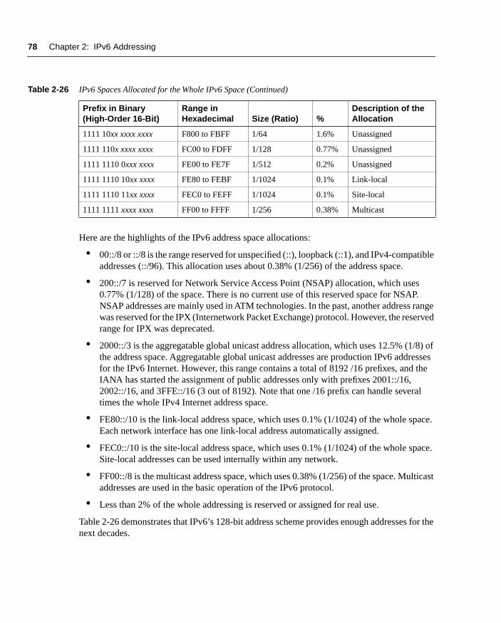
Table 2-26 presents an overview of spaces allocated compared to IPv6’s entire addressing space. The first column, Prefix in Binary, represents the high-order 16-bit of each allocation. The character x means that these bits may have any binary value. The second column is the range in hexadecimal values for the allocation. The next two columns show the ratio and percentage per allocation compared to the whole IPv6 space. The last column describes the specific use of the allocation.
Table 2-26 IPv6 Spaces Allocated for the Whole IPv6 Space
Prefix in Binary (High-Order 16-Bit)
Range in Hexadecimal Size (Ratio) %
Description of the Allocation
0000 0000 xxxx xxxx 0000 to 00FF 1/256 0.38% Unspecified, loopback, IPv4-compatible address
0000 0001 xxxx xxxx 0100 to 01FF 1/256 0.38% Unassigned
0000 001x xxxx xxxx 0200 to 03FF 1/128 0.77% NSAP
0000 010x xxxx xxxx 0400 to 05FF 1/128 0.77% Unassigned
0000 011x xxxx xxxx 0600 to 07FF 1/128 0.77% Unassigned
0000 1xxx xxxx xxxx 0800 to 0FFF 1/32 3.13% Unassigned
0001 xxxx xxxx xxxx 1000 to 1FFF 1/16 6.26% Unassigned
001x xxxx xxxx xxxx 2000 to 3FFF 1/8 12.5% Aggregatable global unicast addresses (IANA)
010x xxxx xxxx xxxx 4000 to 5FFF 1/8 12.5% Unassigned
011x xxxx xxxx xxxx 6000 to 7FFF 1/8 12.5% Unassigned
100x xxxx xxxx xxxx 8000 to 9FFF 1/8 12.5% Unassigned
101x xxxx xxxx xxxx A000 to BFFF 1/8 12.5% Unassigned
110x xxxx xxxx xxxx C000 to DFFF 1/8 12.5% Unassigned
1110 xxxx xxxx xxxx E000 to EFFF 1/16 6.26% Unassigned
1111 0xxx xxxx xxxx F000 to F7FF 1/32 3.13% Unassigned
continues
chpt_02.fm Page 77 Thursday, May 1, 2003 9:55 AM
78 Chapter 2: IPv6 Addressing
Here are the highlights of the IPv6 address space allocations:
• 00::/8 or ::/8 is the range reserved for unspecified (::), loopback (::1), and IPv4-compatible addresses (::/96). This allocation uses about 0.38% (1/256) of the address space.
• 200::/7 is reserved for Network Service Access Point (NSAP) allocation, which uses 0.77% (1/128) of the space. There is no current use of this reserved space for NSAP. NSAP addresses are mainly used in ATM technologies. In the past, another address range was reserved for the IPX (Internetwork Packet Exchange) protocol. However, the reserved range for IPX was deprecated.
• 2000::/3 is the aggregatable global unicast address allocation, which uses 12.5% (1/8) of the address space. Aggregatable global unicast addresses are production IPv6 addresses for the IPv6 Internet. However, this range contains a total of 8192 /16 prefixes, and the IANA has started the assignment of public addresses only with prefixes 2001::/16, 2002::/16, and 3FFE::/16 (3 out of 8192). Note that one /16 prefix can handle several times the whole IPv4 Internet address space.
• FE80::/10 is the link-local address space, which uses 0.1% (1/1024) of the whole space. Each network interface has one link-local address automatically assigned.
• FEC0::/10 is the site-local address space, which uses 0.1% (1/1024) of the whole space. Site-local addresses can be used internally within any network.
• FF00::/8 is the multicast address space, which uses 0.38% (1/256) of the space. Multicast addresses are used in the basic operation of the IPv6 protocol.
• Less than 2% of the whole addressing is reserved or assigned for real use.
Table 2-26 demonstrates that IPv6’s 128-bit address scheme provides enough addresses for the next decades.
1111 10xx xxxx xxxx F800 to FBFF 1/64 1.6% Unassigned
1111 110x xxxx xxxx FC00 to FDFF 1/128 0.77% Unassigned
1111 1110 0xxx xxxx FE00 to FE7F 1/512 0.2% Unassigned
1111 1110 10xx xxxx FE80 to FEBF 1/1024 0.1% Link-local
1111 1110 11xx xxxx FEC0 to FEFF 1/1024 0.1% Site-local
1111 1111 xxxx xxxx FF00 to FFFF 1/256 0.38% Multicast
Table 2-26 IPv6 Spaces Allocated for the Whole IPv6 Space (Continued)
Prefix in Binary (High-Order 16-Bit)
Range in Hexadecimal Size (Ratio) %
Description of the Allocation
chpt_02.fm Page 78 Thursday, May 1, 2003 9:55 AM
Configuring IPv6 on Cisco IOS Software Technology 79
Configuring IPv6 on Cisco IOS Software TechnologyThe Cisco IOS Software technology available on routers supports most features of the IPv6 protocol required to deploy and manage IPv6 networks. This part of the chapter examines IPv6 features implemented on Cisco IOS Software technology. These features are necessary to enable IPv6, activate IPv6 on network interfaces, and configure mechanisms within NDP (Neighbor Discovery Protocol) such as the replacement of ARP, stateless autoconfiguration, prefix advertisement, DAD (Duplicate Address Detection), and prefix renumbering. NDP, stateless autoconfiguration, prefix advertisement, DAD, and prefix renumbering are saved for Chapter 3.
This section focuses on the configuration and operation of the IPv6 addresses in Cisco IOS Software technology. It also assumes that you have successfully installed Cisco IOS software, including IPv6 support, on your router. You can download the Cisco IOS Software with IPv6 support from Cisco.com. Basic information about IPv6 for Cisco technology is available at www.cisco.com/ipv6/.
NOTE To learn how to install the Cisco IOS Software with IPv6 support on your router, refer to Task 1 of the case study near the end of this chapter.
Enabling IPv6 on Cisco IOS Software TechnologyThe first step of enabling IPv6 on a Cisco router is the activation of IPv6 traffic forwarding to forward unicast IPv6 packets between network interfaces. By default, IPv6 traffic forwarding is disabled on Cisco routers.
The ipv6 unicast-routing command is used to enable the forwarding of IPv6 packets between interfaces on the router. The syntax for this command is as follows:
Router(config)#ipv6 unicast-routing
The ipv6 unicast-routing command is enabled on a global basis.
The next step after the completion of this command is the activation of IPv6 on network interfaces.
Enabling CEFv6 on CiscoCisco Express Forwarding (CEF) is also available for IPv6 on Cisco. The behavior of CEFv6 is the same as CEF for IPv4. However, there are new configuration commands for CEFv6 and common commands for both CEFv6 and CEF for IPv4.
The ipv6 cef command enables the central CEFv6 mode. IPv4 CEF must be enabled using the ip cef command. Similarly, IPv4 dCEF must be enabled before dCEFv6. The ipv6 cef com-mand is enabled on a global basis.
chpt_02.fm Page 79 Thursday, May 1, 2003 9:55 AM

80 Chapter 2: IPv6 Addressing
Chapter 4, “Routing on IPv6,” presents in detail current and new commands used to configure and manage CEF for IPv6.
IPv6 Over Data-Link TechnologiesIPv6 is defined to run on almost all data-link technologies such as Ethernet, FDDI, Token Ring, ATM, PPP, Frame Relay, nonbroadcast multiaccess (NBMA), and ARCnet. The following RFCs describe the behavior of the IPv6 protocol on each of these data-link technologies:
• Ethernet—RFC 2464, Transmission of IPv6 Packets over Ethernet Networks
• FDDI—RFC 2467, Transmission of IPv6 Packets over FDDI Networks
• Token Ring—RFC 2470, Transmission of IPv6 Packets over Token Ring Networks
• ATM—RFC 2492, IPv6 over ATM Networks
• PPP—RFC 2472, IP Version 6 over PPP
• Frame Relay—RFC 2590, Transmission of IPv6 Packets over Frame Relay Networks
• NBMA—RFC 2491, IPv6 over Non-Broadcast Multiple Access (NBMA) networks
• ARCnet—RFC 2497, Transmission of IPv6 Packets over ARCnet Networks
• Generic packet tunneling—RFC 2473, Generic Packet Tunneling in IPv6 Specification
• IEEE-1394—RFC 3146, Transmission of IPv6 Packets over IEEE 1394 Networks
Cisco IOS Software technology with IPv6 supports several interface types such as Ethernet, Fast Ethernet, Gigabit Ethernet, Cisco HDLC, PPP, Frame Relay PVC, ATM PVC, tunnels, and loopback. Configuration examples presented in this book are mostly focused on Ethernet technology because this is the most popular data-link technology used in networks.
IPv6 Over EthernetSimilar to IPv4, IPv6 runs over any Ethernet technology. However, the protocol ID value specified in Ethernet frames that carry IPv6 packets is different from the protocol ID in IPv4. The protocol ID value within Ethernet frames identifies the Layer 3 protocol used such as IPv4, IPv6, or even other protocols such as IPX, DECnet, AppleTalk, and so on.
As shown in Table 2-27, the protocol ID is 0x0800 with IPv4 and 0x86DD with IPv6.
Table 2-27 Protocol ID Values for IPv4 and IPv6
Protocol Protocol ID in Ethernet Frames
IPv4 0x0800
IPv6 0x86DD
chpt_02.fm Page 80 Thursday, May 1, 2003 9:55 AM
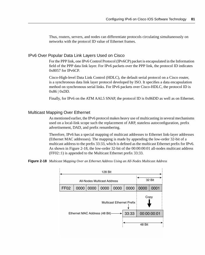
Configuring IPv6 on Cisco IOS Software Technology 81
Thus, routers, servers, and nodes can differentiate protocols circulating simultaneously on networks with the protocol ID value of Ethernet frames.
IPv6 Over Popular Data Link Layers Used on CiscoFor the PPP link, one IPv6 Control Protocol (IPv6CP) packet is encapsulated in the Information field of the PPP data link layer. For IPv6 packets over the PPP link, the protocol ID indicates 0x8057 for IPv6CP.
Cisco-High-level Data Link Control (HDLC), the default serial protocol on a Cisco router, is a synchronous data link layer protocol developed by ISO. It specifies a data encapsulation method on synchronous serial links. For IPv6 packets over Cisco-HDLC, the protocol ID is 0x86 | 0xDD.
Finally, for IPv6 on the ATM AAL5 SNAP, the protocol ID is 0x86DD as well as on Ethernet.
Multicast Mapping Over EthernetAs mentioned earlier, the IPv6 protocol makes heavy use of multicasting in several mechanisms used on a local-link scope such the replacement of ARP, stateless autoconfiguration, prefix advertisement, DAD, and prefix renumbering.
Therefore, IPv6 has a special mapping of multicast addresses to Ethernet link-layer addresses (Ethernet MAC addresses). The mapping is made by appending the low-order 32-bit of a multicast address to the prefix 33:33, which is defined as the multicast Ethernet prefix for IPv6. As shown in Figure 2-18, the low-order 32-bit of the 00:00:00:01 all-nodes multicast address (FF02::1) is appended to the Multicast Ethernet prefix 33:33.
Figure 2-18 Multicast Mapping Over an Ethernet Address Using an All-Nodes Multicast Address
128 Bit
Copy
FF02 0000 0000 0000 0000 0000
32 BitAll-Nodes Multicast Address
0000 0001
Ethernet MAC Address (48 Bit) 00:00:00:0133:33
Multicast Ethernet Prefix
48 Bit
chpt_02.fm Page 81 Thursday, May 1, 2003 9:55 AM

82 Chapter 2: IPv6 Addressing
The 48-bit address 33:33:00:00:00:01 represents the Ethernet MAC address (link-layer address) that is used as destination in the Ethernet frame to send a packet to the IPv6 destination FF02::1 (all-nodes multicast address). By default, all nodes that are IPv6-enabled on this local link listen and get any IPv6 packets using 33:33:00:00:00:01 as the destination in the Ethernet MAC address. This is an example of the all-nodes multicast address, but all other multicast assigned addresses presented in the “Multicast Address” section are used in the same way.
EUI-64 Format of an IPv6 AddressLink-local, site-local, and the stateless autoconfiguration mechanism as defined in RFC 2462 use EUI-64 format to make their IPv6 addresses. Stateless autoconfiguration is a mechanism that allows nodes on a network to configure their IPv6 addresses themselves without any intermediary device, such as a DHCP server.
The link-local address and stateless autoconfiguration are functions of IPv6 that automatically expand the Ethernet MAC address based on a 48-bit format into a 64-bit format (EUI-64). The conversion from 48-bit to 64-bit is a two-step operation.
As shown in Figure 2-19, the first step consists of inserting the value FFFE in the middle of the 48-bit link-layer address between the OUI section (vendor code) and the ID section (similar to a serial number). The original Ethernet MAC address presented here based on 48-bit is 00:50:3E:E4:4C:00.
Figure 2-19 First Step of the 48-Bit MAC Address Conversion into EUI-64 Format
As shown in Figure 2-20, the second and last step consists of setting the seventh bit of the 64-bit address. This bit identifies the 48-bit address’s uniqueness or lack thereof. An Ethernet address may have two significances. The address can be globally or locally managed. Globally managed means that you use the vendor MAC address, such as 08-00-2B-xx-xx-xx (a DEC example). Locally means that you can rewrite the MAC address with your own value (a Sun example). In this case, the seventh bit indicates 1 for local and 0 for global. However, in EUI-64 format, the value is reversed: 0 for local and 1 for global. In summary, for IPv6 addresses using EUI-64 format, if the seventh bit is set to 1, the address is globally unique. Otherwise, it is local.
00 50 3E
00 50 3E
E4 4C 00
E4 4C 00
FF FE
Step #1
00:50:3E:E4:4C:00MAC
Address
(48 Bit)
chpt_02.fm Page 82 Thursday, May 1, 2003 9:55 AM

Configuring IPv6 on Cisco IOS Software Technology 83
Figure 2-20 Second Step of the 48-Bit MAC Address Conversion into EUI-64 Format
Enabling IPv6 on Network InterfacesAfter IPv6 forwarding is enabled on the router, the next step is assigning an IPv6 address to an interface. There are different methods to configure IPv6 addresses under a Cisco router. This section teaches you different ways to configure IPv6 addresses on Cisco IOS Software technology.
Static Address ConfigurationAs shown in Table 2-28, the command ipv6 address may be used to configure the link-local address (FE80::/10), the site-local (FEC0::/10) address, or an aggregatable global unicast address (2000::/3) on network interface. This method is similar to the static address configura-tion, thus, the entire IPv6 address must be specified and must have a legal representation as pre-sented earlier in this chapter.
Table 2-28 ipv6 address Command
Command Description
Step 1
Router(config)#interface interface-type interface-number
Specifies an interface type and interface number.
Example
RouterA(config)#interface FastEthernet 0/0
Interface FastEthernet 0/0 is selected.
Step 2
Router(config-if)#ipv6 address ipv6-address/prefix-length [link-local]
Specifies an IPv6 address and prefix length to be assigned to the network interface. By default, when a site-local or aggregatable glo-bal unicast address is specified with this com-mand, the link-local address is automatically configured. The default prefix length is 64-bit.
continues
000000X0
Where X=1 = Unique
0 = Not Unique
00 50 3E E4 4C 00
Step #2
FF FE
X = 7th Bit
Binary Value
02 50 3E E4 4C 00FF FE
Step #1
chpt_02.fm Page 83 Thursday, May 1, 2003 9:55 AM

84 Chapter 2: IPv6 Addressing
NOTE As soon as you have assigned a site-local or aggregatable global unicast IPv6 address with a prefix length to a network interface on a Cisco router, the result is an advertisement of the specified prefix on the router’s local interface. Refer to Chapter 3 for detailed information about prefix advertisement and stateless autoconfiguration.
NOTE You can assign multiple site-local and aggregatable global unicast IPv6 addresses to each interface, but only one link-local address is permitted. Moreover, in the current Cisco IOS Software release, a site-local address is treated as an aggregatable global unicast address.
NOTE As described in RFC 2373, the recommended length of an IPv6 prefix assigned to a subnet is 64-bit.
Configuring the Loopback InterfaceYou can configure site-local or aggregatable global unicast addresses on the loopback interface using the ipv6 address command. In the following example, the interface loopback0 is selected:
RouterA(config)#interface loopback0
Example
RouterA(config-if)#ipv6 address 2001:0410:0:1:0:0:0:1/64
The aggregatable global unicast address 2001:0410:0:1:0:0:0:1/64 is configured on the interface. After the completion of this com-mand, the link-local address is automatically configured.
Example
RouterA(config-if)#ipv6 address FEC0:0:0:1::1/64
The site-local address FEC0:0:0:1::1/64 is con-figured on the interface. After the completion of this command, the link-local address is automatically configured.
Example
RouterA(config-if)#ipv6 address FE80:0:0:0:0123:0456:0789:0abc link-local
The link-local address FE80:0:0:0:0123:0456:0789:0abc is configured here. This command with the link-local argument can be used to override the default link-local address assigned by the router.
Table 2-28 ipv6 address Command (Continued)
Command Description
chpt_02.fm Page 84 Thursday, May 1, 2003 9:55 AM

Configuring IPv6 on Cisco IOS Software Technology 85
In the following example, the address fec0:0:0:9::1/128 is assigned to the loopback0 interface:
RouterA(config-if)#ipv6 address fec0:0:0:9::1/128
Static Address Configuration Using EUI-64 FormatWith this method, using the ipv6 address command, you can configure addresses on interfaces using EUI-64 format, as discussed earlier in this chapter. It is important to specify the address’s high-order 64-bit (IPv6 prefix). Then the router automatically completes the low-order 64-bit using EUI-64 format.
The following example specifies the prefix and prefix length to assign to the interface:
Router(config-if)#ipv6 address ipv6-prefix/prefix-length eui-64
The router completes the low-order 64-bit using EUI-64 format. After this command is completed, the link-local address is automatically configured.
In the following example, the aggregatable global unicast prefix 2001:0410:0:1::/64 is used to configure the address. The aggregatable global unicast and link-local addresses are automatically configured:
RouterA(config-if)#ipv6 address 2001:0410:0:1::/64 eui-64
In the following example, the site-local prefix FEC0:0:0:1::/64 is used to configure the address. The site-local and link-local addresses are automatically configured:
RouterA(config-if)#ipv6 address FEC0:0:0:1::/64 eui-64
NOTE You can assign multiple site-local and aggregatable global unicast IPv6 addresses using this command.
Enabling Only IPv6 on a Network InterfaceYou can also enable just IPv6 on an interface without specifying an aggregatable global unicast or site-local address by using the ipv6 enable command, as shown here:
Router(config-if)#ipv6 enable
This command also automatically configures the link-local address on the interface. By default, this command is disabled.
Configuring an Unnumbered InterfaceYou can use the command ipv6 unnumbered to instruct an interface to use another interface’s aggregatable global unicast address as a source address for packets originating from the unnumbered interface, as shown here:
Router(config-if)#ipv6 unnumbered interface
chpt_02.fm Page 85 Thursday, May 1, 2003 9:55 AM
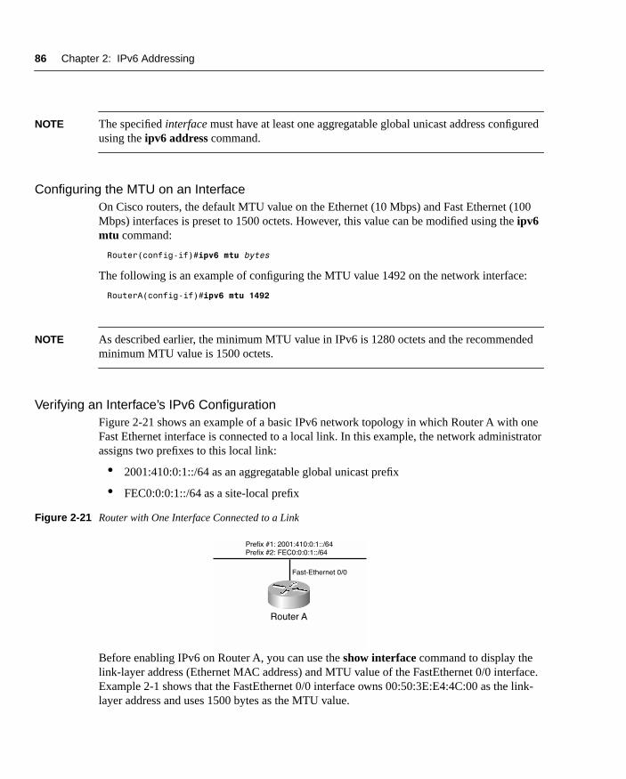
86 Chapter 2: IPv6 Addressing
NOTE The specified interface must have at least one aggregatable global unicast address configured using the ipv6 address command.
Configuring the MTU on an InterfaceOn Cisco routers, the default MTU value on the Ethernet (10 Mbps) and Fast Ethernet (100 Mbps) interfaces is preset to 1500 octets. However, this value can be modified using the ipv6 mtu command:
Router(config-if)#ipv6 mtu bytes
The following is an example of configuring the MTU value 1492 on the network interface:
RouterA(config-if)#ipv6 mtu 1492
NOTE As described earlier, the minimum MTU value in IPv6 is 1280 octets and the recommended minimum MTU value is 1500 octets.
Verifying an Interface’s IPv6 ConfigurationFigure 2-21 shows an example of a basic IPv6 network topology in which Router A with one Fast Ethernet interface is connected to a local link. In this example, the network administrator assigns two prefixes to this local link:
• 2001:410:0:1::/64 as an aggregatable global unicast prefix
• FEC0:0:0:1::/64 as a site-local prefix
Figure 2-21 Router with One Interface Connected to a Link
Before enabling IPv6 on Router A, you can use the show interface command to display the link-layer address (Ethernet MAC address) and MTU value of the FastEthernet 0/0 interface. Example 2-1 shows that the FastEthernet 0/0 interface owns 00:50:3E:E4:4C:00 as the link-layer address and uses 1500 bytes as the MTU value.
Prefix #1: 2001:410:0:1::/64
Prefix #2: FEC0:0:0:1::/64
Fast-Ethernet 0/0
Router A
chpt_02.fm Page 86 Thursday, May 1, 2003 9:55 AM

Configuring IPv6 on Cisco IOS Software Technology 87
Then you can enable IPv6 on Router A and configure an address on interface FastEthernet 0/0. As shown in Example 2-2, the command ipv6 address 2001:410:0:1::/64 eui-64 forces the router to complete the address’s low-order 64-bit by using the interface’s link-layer address (Ethernet MAC address). The Ethernet MAC address used in this example is 00:50:3E:E4:4C:00.
Finally, the show ipv6 interface command allows you to display parameters related to the IPv6 configuration applied to a specific interface.
In Example 2-3, as soon as IPv6 is enabled on this interface, the link-local address FE80::250:3EFF:FEE4:4C00 is automatically enabled. The EUI-64 option specified with the ipv6 address command instructs the router to append the low-order 64-bit 250:3EFF:FEE4:4C00 to the aggregatable prefix 2001:410:0:1::/64. However, the site-local address FEC0::1:0:0:1:1 was statically configured. Note that only one link-local address is enabled, although there are two unicast addresses.
Example 2-1 Displaying an Interface’s Link-Layer Address and MTU Value Using the show interface Command
RouterA#show interface fastEthernet 0/0
FastEthernet0/0 is up, line protocol is up Hardware is AmdFE, address is 0050.3ee4.4c00 (bia 0050.3ee4.4c00) MTU 1500 bytes, BW 10000 Kbit, DLY 1000 usec,<output omitted>
Example 2-2 Enabling IPv6 on the Router and Configuring Two Addresses on Interface FastEthernet 0/0 Using the ipv6 address Command
RouterA#configure terminalRouterA(config)#ipv6 unicast-routingRouterA(config)#int fastethernet 0/0RouterA(config-if)#ipv6 address 2001:410:0:1::/64 eui-64RouterA(config-if)#ipv6 address FEC0::1:0:0:1:1/64RouterA(config-if)#exitRouterA(config)#exit
Example 2-3 show ipv6 interface Displays Parameters Related to Interface FastEthernet 0/0
RouterA#show ipv6 interface fastEthernet 0/0FastEthernet0/0 is up, line protocol is up IPv6 is enabled, link-local address is FE80::250:3EFF:FEE4:4C00 Global unicast address(es): 2001:410:0:1:250:3EFF:FEE4:4C00, subnet is 2001:410:0:1::/64 FEC0::1:0:0:1:1, subnet is FEC0:0:0:1::/64 Joined group address(es): FF02::1 FF02::2
continues
chpt_02.fm Page 87 Thursday, May 1, 2003 9:55 AM

88 Chapter 2: IPv6 Addressing
As shown in Example 2-3, the interface automatically joins several multicast assigned addresses. Here is the meaning of each multicast assigned address:
• FF02::1—Represents all nodes and routers on the link-local.
• FF02::2—Represents all routers on the link-local.
• FF02::1:FF01:1—Solicited-node multicast address used for the mechanisms that replace ARP. This address is also used by DAD. One solicited-node multicast address is enabled for each unicast address configured on the interface. Therefore, this address is the solicited-node multicast address related to the unicast address FEC0::1:0:0:1:1.
• FF02::1:FFE4:4C00—Solicited-node multicast address related to the unicast address 2001:410:0:1:250:3EFF:FEE4:4C00.
NOTE Mechanisms that replace ARP is covered in detail in Chapter 3.
SummaryIn this chapter, you learned about the new IPv6 header format and the impact of IPv6 on User Datagram Protocol (UDP), Transport Control Protocol (TCP), and Maximum Transmission Unit (MTU). You also learned about IPv6’s addressing architecture, with its different kinds of IPv6 addresses such as link-local, site-local, aggregatable global unicast, loopback, unspeci-fied, IPv4-compatible, multicast assigned, solicited-node multicast, and anycast. This chapter also covered IPv6 over Ethernet, multicast mapping over Ethernet, and EUI-64 format.
You learned how to configure and operate Cisco routers with IPv6. You saw examples of how to enable IPv6 on a router and configure static IPv6 addresses on network interfaces such as aggregatable global unicast, site-local, and link-local. Then you configured IPv6 addresses using EUI-64 format and defined the MTU on the interface. Finally, you verified aggregatable global unicast, site-local, link-local, multicast assigned, and solicited-node multicast addresses enabled on the router’s network interfaces.
FF02::1:FF01:1 FF02::1:FFE4:4C00 MTU is 1500 bytes<output omitted>
Example 2-3 show ipv6 interface Displays Parameters Related to Interface FastEthernet 0/0 (Continued)
chpt_02.fm Page 88 Thursday, May 1, 2003 9:55 AM

Configuration Exercise: Configuring an IPv6 Network Using Cisco Routers 89
Configuration Exercise: Configuring an IPv6 Network Using Cisco Routers
Complete the following exercise to configure IPv6 on a network to practice skills learned in this chapter.
NOTE Configuration Exercises allow you to practice your skills and knowledge by configuring IPv6 on a Cisco router using commands presented in this chapter. In the exercise presented here, only one router with multiple Fast Ethernet interfaces provides IPv6 connectivity to nodes on a network. This exercise assumes that you have minimal experience with the command-line interface (CLI) and that you can download a new Cisco IOS Software from the Cisco website.
ObjectivesIn the following exercise, you will complete the following tasks:
1 Install a new Cisco IOS Software with IPv6 support on a Cisco router. The filename of the new image is c2600-is-mz.2001120.
2 Enable IPv6 on the Cisco router.
3 Assign IPv6 addresses to interfaces.
4 Verify interfaces and addresses assigned.
Network Architecture for Tasks 1 and 2Figure 2-22 shows a basic network architecture used for Tasks 1 and 2.
Figure 2-22 Network Architecture for Enabling IPv6 on a Router
Router A
192.168.1.1/24
FEC0:0:0:1001::1/64
FE 0/0 FE 0/1
FEC0:0:0:1002::1/64
192.168.1.1/24
TFTP Server
chpt_02.fm Page 89 Thursday, May 1, 2003 9:55 AM

90 Chapter 2: IPv6 Addressing
Command ListIn this configuration exercise, you will use the commands shown in Table 2-29. Refer to this list during the exercise.
Task 1: Basic Router Setup and Installing New Cisco IOS Software with IPv6 Support
Configure a basic setup on Router A to install the new IOS on the router with IPv6 support. The TFTP server is connected to the same link-layer network as the Fast Ethernet (FE) 0/0 interface. The TFTP server can only be reached over IPv4 using 192.168.1.1 as the IPv4 address.
Step 1 The name of your router is Router A. Set the host name on your router. Which command is used to perform this task?
Table 2-29 Configuration Exercise Command List
Command Description
copy running-config startup-config
Saves a current configuration to NVRAM.
copy tftp flash Installs a new IOS on a router using a TFTP server.
hostname name Configures the router’s name.
interface interface-type interface-number
Specifies an interface type and interface number.
ip address ip-address network-mask
Configures an IPv4 address to an interface.
ip cef Enables CEF for IPv4.
ipv6 cef Enables CEF for IPv6.
ipv6 unicast-routing Enables IPv6 traffic forwarding.
ipv6 address ipv6-address/prefix-length
Configures an IPv6 static address with a prefix length.
no ip address ip-address network-mask
Disables an IPv4 address.
show interface interface-type interface-number
Displays general information about the interface.
show ipv6 Displays general information about IPv6 support on a router.
show ipv6 interface interface-type interface-number
Displays the IPv6 configuration applied to an interface type and interface number.
chpt_02.fm Page 90 Thursday, May 1, 2003 9:55 AM

Configuration Exercise: Configuring an IPv6 Network Using Cisco Routers 91
The following shows how to configure the host name on Router A:
Router#conf tRouter(config)#hostname RouterARouter(config)#exitRouterA#
Step 2 Assign an IPv4 address with the netmask value shown in the following table to the router’s interface FE 0/0. Other interfaces are not used in the basic router setup task. What command used on the Cisco router configures an IPv4 address on a network interface?
The following shows how to configure an IPv4 address on interface FE 0/1 of Router A:
RouterA(config)#interface fastEthernet 0/0RouterA(config-if)#ip address 192.168.1.2 255.255.255.0RouterA(config-if)#exitRouterA(config)#exit
Step 3 On the router, enter the command to download and install a new IOS with IPv6 support using a TFTP server. What command installs an IOS from a TFTP server?
The following command shows how to install a new IOS on a router using a TFTP server:
RouterA#copy tftp flashAddress or name of remote host []? 192.168.1.1Source filename []? c2600-is-mz.20011207Destination filename [c2600-is-mz.20011207]?Do you want to over write? [confirm] ENTERAccessing tftp://192.168.1.1/c2600-is-mz.20011207...Erase flash: before copying? [confirm] ENTERErasing the flash filesystem will remove all files! Continue? [confirm]Erasing device... eeeeeeeeeeeeeeeeeeeeeeeeeeeeeeeeeeeeeeeeeeeeeeeeeeeeeeeeeeeeee ...erasedErase of flash: completeLoading c2600-is-mz.20011207 from 192.168.1.1 (via FastEthernet0/0):<output omitted>[OK - 12460516/24920064 bytes]Verifying checksum... OK (0xE9F1)12460516 bytes copied in 106.92 secs (117552 bytes/sec)
Step 4 As soon as the new image is successfully downloaded, reboot the router, log into enable mode, and verify that the IPv6-enabled image is fully installed in the router. What command verifies IPv6 support in the IOS?
Router’s Interface IPv4 Address Netmask
Fast Ethernet 0/0 192.168.1.2 255.255.255.0
chpt_02.fm Page 91 Thursday, May 1, 2003 9:55 AM

92 Chapter 2: IPv6 Addressing
The following command can be used to verify whether IPv6 support is enabled:
RouterA#show ipv6 ? access-list Summary of access lists cef Cisco Express Forwarding for IPv6 interface IPv6 interface status and configuration mtu MTU per destination cache neighbors Show IPv6 neighbor cache entries prefix-list List IPv6 prefix lists protocols IPv6 Routing Protocols rip RIP routing protocol status route Show IPv6 route table entries routers Show local IPv6 routers traffic IPv6 traffic statistics tunnel Summary of IPv6 tunnelsRouterA#show ipv6
NOTE If a syntax error occurs here, it indicates that the router is not running an IOS with IPv6 support.
Step 5 You may remove the IPv4 address on interface FE 0/1, because this configuration exercise is entirely focused on IPv6. What command used on the Cisco router removes an IPv4 address on a network interface?
The following removes the IPv4 address on interface FE 0/0 of Router A:
RouterA(config)#interface fastEthernet 0/0RouterA(config-if)#no ip address 192.168.1.2 255.255.255.0RouterA(config-if)#exitRouterA(config)#exit
Step 6 Save the current configuration to NVRAM:
RouterA#copy running-config startup-configDestination filename [startup-config]?Building configuration...[OK]
Task 2: Enable IPv6 on the Router and Configure Static AddressesComplete the following steps:
Step 1 Enter the command to enable IPv6 traffic forwarding on the router to forward unicast IPv6 packets between interfaces. Then enable CEFv6 in the router. What commands will you use?
RouterA#conf tRouterA(config)#ipv6 unicast-routingRouterA(config)#ip cefRouterA(config)#ipv6 cefRouterA(config)#exit
chpt_02.fm Page 92 Thursday, May 1, 2003 9:55 AM
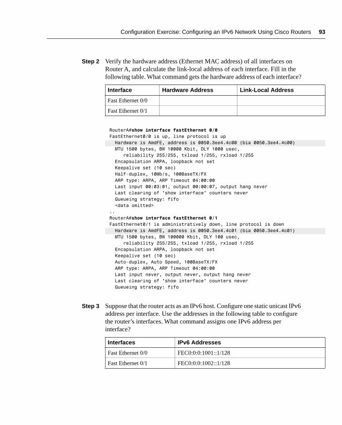
Configuration Exercise: Configuring an IPv6 Network Using Cisco Routers 93
Step 2 Verify the hardware address (Ethernet MAC address) of all interfaces on Router A, and calculate the link-local address of each interface. Fill in the following table. What command gets the hardware address of each interface?
Step 3 Suppose that the router acts as an IPv6 host. Configure one static unicast IPv6 address per interface. Use the addresses in the following table to configure the router’s interfaces. What command assigns one IPv6 address per interface?
Interface Hardware Address Link-Local Address
Fast Ethernet 0/0
Fast Ethernet 0/1
RouterA#show interface fastEthernet 0/0FastEthernet0/0 is up, line protocol is up Hardware is AmdFE, address is 0050.3ee4.4c00 (bia 0050.3ee4.4c00) MTU 1500 bytes, BW 10000 Kbit, DLY 1000 usec, reliability 255/255, txload 1/255, rxload 1/255 Encapsulation ARPA, loopback not set Keepalive set (10 sec) Half-duplex, 10Mb/s, 100BaseTX/FX ARP type: ARPA, ARP Timeout 04:00:00 Last input 00:03:01, output 00:00:07, output hang never Last clearing of "show interface" counters never Queueing strategy: fifo <data omitted>..RouterA#show interface fastEthernet 0/1FastEthernet0/1 is administratively down, line protocol is down Hardware is AmdFE, address is 0050.3ee4.4c01 (bia 0050.3ee4.4c01) MTU 1500 bytes, BW 100000 Kbit, DLY 100 usec, reliability 255/255, txload 1/255, rxload 1/255 Encapsulation ARPA, loopback not set Keepalive set (10 sec) Auto-duplex, Auto Speed, 100BaseTX/FX ARP type: ARPA, ARP Timeout 04:00:00 Last input never, output never, output hang never Last clearing of "show interface" counters never Queueing strategy: fifo
Interfaces IPv6 Addresses
Fast Ethernet 0/0 FEC0:0:0:1001::1/128
Fast Ethernet 0/1 FEC0:0:0:1002::1/128
chpt_02.fm Page 93 Thursday, May 1, 2003 9:55 AM

94 Chapter 2: IPv6 Addressing
RouterA#conf tEnter configuration commands, one per line. End with CNTL/Z.RouterA(config)#interface fastEthernet 0/0RouterA(config-if)#ipv6 address fec0:0:0:1001::1/128RouterA(config-if)#interface fastEthernet 0/1RouterA(config-if)#ipv6 address fec0:0:0:1002::1/128RouterA(config)#exit
Step 4 Verify the static and link-local addresses of each interface. What command displays IPv6 addresses used on an interface? Then compare the link-local addresses with those calculated in Step 2. Are they similar?
RouterA#show ipv6 interface fastEthernet 0/0FastEthernet0/0 is up, line protocol is up IPv6 is enabled, link-local address is FE80::250:3EFF:FEE4:4C00 Global unicast address(es): FEC0:0:0:1001::1, subnet is FEC0:0:0:1001::/128 Joined group address(es): FF02::1 FF02::2 FF02::1:FF00:1 FF02::1:FFE4:4C00 MTU is 1500 bytes ICMP error messages limited to one every 100 milliseconds ICMP redirects are enabled ND DAD is enabled, number of DAD attempts: 1 ND reachable time is 30000 milliseconds ND advertised reachable time is 0 milliseconds ND advertised retransmit interval is 0 milliseconds ND router advertisements are sent every 200 seconds ND router advertisements live for 1800 seconds Hosts use stateless autoconfig for addresses.
RouterA#show ipv6 interface fastEthernet 0/1FastEthernet0/1 is administratively down, line protocol is up IPv6 is enabled, link-local address is FE80::250:3EFF:FEE4:4C01 Global unicast address(es): FEC0:0:0:1002::1, subnet is FEC0:0:0:1002::/128 Joined group address(es): FF02::1 FF02::2 FF02::1:FF00:1 FF02::1:FFE4:4C01 MTU is 1500 bytes ICMP error messages limited to one every 100 milliseconds ICMP redirects are enabled ND DAD is enabled, number of DAD attempts: 1 ND reachable time is 30000 milliseconds ND advertised reachable time is 0 milliseconds ND advertised retransmit interval is 0 milliseconds ND router advertisements are sent every 200 seconds ND router advertisements live for 1800 seconds Hosts use stateless autoconfig for addresses.
link-local address is FE80::250:3EFF:FEE4:4C00
FEC0:0:0:1001::1
link-local address is FE80::250:3EFF:FEE4:4C01
FEC0:0:0:1002::1
chpt_02.fm Page 94 Thursday, May 1, 2003 9:55 AM

Review Questions 95
Step 5 Save the current configuration to NVRAM:
RouterA#copy running-config startup-configDestination filename [startup-config]?Building configuration...
Review QuestionsAnswer the following questions, and then refer to Appendix B, “Answers to Review Questions,” for the answers.
1 For each of the fields in the following table, give the field’s length and indicate whether it is used in the IPv4 header or IPv6 header.
2 List the fields removed from the IPv4 header.
Field Length in Bits IPv4 Header IPv6 Header
Type of Service
Identification
Version
Time to live
Header checksum
Header length
Traffic Class
Total Length
Flow Label
Flags
Padding
Extension header
Payload Length
Protocol Number
Hop Limit
Source Address
Destination Address
Options
Next Header
Fragment Offset
chpt_02.fm Page 95 Thursday, May 1, 2003 9:55 AM

96 Chapter 2: IPv6 Addressing
3 What new field is added in the IPv6 header?
4 Describe the use of the Next Header field in the IPv6 header.
5 List the extension headers that may be placed after the basic IPv6 header, and place them in the order they must appear.
6 What is mandatory with UDP when used over IPv6?
7 What is recommended as a mechanism for nodes in IPv6 to avoid fragmentation?
8 What are IPv6’s minimum MTU and recommended minimum MTU?
9 What are the three representations of IPv6 addresses?
10 Compress the following IPv6 addresses into the shortest form possible.
11 Describe the IPv6 address representation for URL.
12 List the three kinds of addresses in the IPv6 addressing architecture.
13 For each of the following address types, find the IPv6 prefix and write the address in the compressed representation.
Unspecified
Loopback
IPv4-compatible IPv6
Link-local
Site-local
Multicast
Solicited-node multicast
Aggregatable global unicast
14 What is a link-local address?
Preferred Representation Compressed Representation
A0B0:10F0:A110:1001:5000:0000:0000:0001
0000:0000:0000:0000:0000:0000:0000:0001
2001:0000:0000:1234:0000:0000:0000:45FF
3ffe:0000:0010:0000:1010:2a2a:0000:1001
3FFE:0B00:0C18:0001:0000:1234:AB34:0002
FEC0:0000:0000:1000:1000:0000:0000:0009
FF80:0000:0000:0000:0250:FFFF:FFFF:FFFF
chpt_02.fm Page 96 Thursday, May 1, 2003 9:55 AM

References 97
15 What is similar to the site-local address in IPv4?
16 In the following table, list the solicited-node multicast address that corresponds to each unicast address.
17 Give the length in bits of the host and site parts of an aggregatable global unicast IPv6 address.
18 What three prefixes are assigned by IANA and are available as public addresses in IPv6?
19 What is the Cisco IOS Software command to enable IPv6 on a Cisco router?
20 What protocol ID is used for IPv6 in Ethernet frames?
21 Explain how IPv6 multicast addresses are mapped over Ethernet.
22 Generate IPv6 interface IDs (in EUI-64 format) from the following Ethernet link-layer addresses.
23 What command assigns one IPv6 address to an interface using EUI-64 format?
24 What is the goal of the path MTU discovery mechanism?
ReferencesRFC 768, User Datagram Protocol, J. Postel, IETF, www.ietf.org/rfc/|rfc768.txt, August 1980
RFC 791, Internet Protocol, DARPA Internet Program, Protocol Specification, USC, IETF, www.ietf.org/rfc/rfc791.txt, September 1981
Unicast Address Solicited-Node Multicast Address
A0B0:10F0:A110:1001:5000:0000:0000:0001
2001:0000:0000:1234:0000:0000:0000:45FF
3ffe:0000:0010:0000:1010:2a2a:0000:1001
3FFE:0B00:0C18:0001:0000:1234:AB34:0002
FEC0:0000:0000:1000:1000:0000:0000:0009
Ethernet Link-Layer Address IPv6 Interface ID
00:90:27:3a:9e:9a
00:90:27:3a:8d:c3
00:00:86:4b:fe:ce
chpt_02.fm Page 97 Thursday, May 1, 2003 9:55 AM

98 Chapter 2: IPv6 Addressing
RFC 792, Internet Control Message Protocol, J. Postel, IETF, www.ietf.org/ietf/rfc/rfc792.txt, September 1981
RFC 793, Transmission Control Protocol, DARPA Internet Program, IETF, www.ietf.org/rfc/rfc793.txt, September 1981
RFC 1191, Path MTU Discovery, J. Mogul, S. Deering, IETF, www.ietf.org/ietf/rfc/rfc1191.txt, November 1990
RFC 1981, Path MTU Discovery for IP version 6, J. McCann et al., IETF, www.ietf.org/rfc/rfc1981.txt, August 1996
RFC 2373, IP Version 6 Addressing Architecture, R. Hinden, S. Deering, IETF, www.ietf.org/rfc/rfc2373.txt, July 1998
RFC 2374, An IPv6 Aggregatable Global Unicast Address Format, R. Hinden, S. Deering, M. O’Dell, IETF, www.ietf.org/rfc/rfc2374.txt, July 1998
RFC 2460, Internet Protocol, Version 6 (IPv6) Specification, S. Deering, R. Hinden, IETF, www.ietf.org/rfc/rfc2460.txt, December 1998
RFC 2461, Neighbor Discovery for IP Version 6 (IPv6), T. Narten, E. Normark, W. Simpson, IETF, www.ietf.org/rfc/rfc2461.txt, December 1998
RFC 2462, IPv6 Stateless Address Autoconfiguration, S. Thomson, T. Narten, IETF, www.ietf.org/rfc/rfc2462.txt, December 1998
RFC 2463, Internet Control Message Protocol (ICMPv6) for the Internet Protocol version 6 (IPv6), A. Conta, S. Deering, IETF, www.ietf.org/rfc/rfc2463.txt, December 1998
RFC 2464, Transmission of IPv6 Packets over Ethernet Networks, M. Crawford, IETF, www.ietf.org/rfc/rfc2464.txt, December 1998
RFC 2467, Transmission of IPv6 Packets over FDDI Networks, M. Crawford, IETF, www.ietf.org/rfc/rfc2467.txt, December 1998
RFC 2470, Transmission of IPv6 Packets over Token Ring Networks, M. Crawford, T. Narten, S. Thomas, IETF, www.ietf.org/rfc/rfc2470.txt, December 1998
RFC 2472, IP Version 6 over PPP, D. Haskin, E. Allen, IETF, www.ietf.org/rfc/rfc2472.txt, December 1998
RFC 2473, Generic Packet Tunneling in IPv6 Specification, A. Conta, S. Deering, IETF, www.ietf.org/rfc/rfc2473.txt, December 1998
RFC 2491, IPv6 over Non-Broadcast Multiple Access (NBMA) Networks, G. Armitage et al., IETF, www.ietf.org/rfc/rfc2491.txt, January 1999
RFC 2492, IPv6 over ATM Networks, G. Armitage, P. Schulter, M. Jork, IETF, www.ietf.org/rfc/rfc2492.txt, January 1999
chpt_02.fm Page 98 Thursday, May 1, 2003 9:55 AM

References 99
RFC 2497, Transmission of IPv6 Packets over ARCnet Networks, I. Souvatzis, IETF, www.ietf.org/rfc/rfc2497.txt, January 1999
RFC 2529, Transmission of IPv6 over IPv4 Domains without Explicit Tunnels, B. Carpenter, C. Jung, IETF, www.ietf.org/rfc/rfc2529.txt, March 1999
RFC 2590, Transmission of IPv6 Packets over Frame Relay Networks Specification, A. Conta, A. Malis, M. Mueller, IETF, www.ietf.org/rfc/rfc2590.txt, May 1999
RFC 2675, IPv6 Jumbograms, D. Borman, S. Deering, R. Hinden, IETF, www.ietf.org/rfc/rfc2675.txt, August 1999
RFC 2711, IPv6 Router Alert Option, C. Partridge, A. Jackson, IETF, www.ietf.org/rfc/rfc2711.txt, October 1999
RFC 2732, Format for Literal IPv6 Addresses in URL’s, R. Hinden, B. Carpenter, L. Masinter, IETF, www.ietf.org/rfc/rfc2732.txt, December 1999
RFC 3146, Transmission of IPv6 Packets over IEEE 1394 Networks, K. Fujisawa, A. Onoe, IETF, www.ietf.org/rfc/rfc3146.txt, October 2001
RFC 3177, IAB/IESG Recommendations on IPv6 Address Allocations to Sites, IAB, IETF, www.ietf.org/rfc/rfc3177.txt, September 2001
chpt_02.fm Page 99 Thursday, May 1, 2003 9:55 AM