“the original portable pool” ROUND POOLS POOL ASSEMBLY …...liner. Consult your Doughboy pool...
18
ROUND POOLS POOL ASSEMBLY AND INSTALLATION INSTRUCTIONS THINK “SAFETY FIRST” Safe and correct use of your new Doughboy pool means swimming and wading only. DO NOT DIVE OR JUMP! The above-ground pool is not designed for these activities! INSTALLATION Installation of a Doughboy pool is not very hard, but it is a big job. The job will be easier if two or three friends help with the installation. Follow all instructions exactly. Your pool warranty is void if pool assembly and installation instructions are not followed 100%. Read all instructions provided with accessories such as filter, pump, skimmer, etc. prior to starting. Plan 3-5 days for pool assembly and installation. Avoid windy days. Before you start, check to see that you have the correct number of parts. Use your Parts List, which is broken down by carton. Do not throw away any of the inspection slips or cartons until you are sure you have all the parts. Your dealer will promptly replace any missing parts. The warranty is void if the design of the pool is altered in any way. No changes may be made to any of the parts. The pool must be assembled according to Doughboy’s instructions. You must be completely satisfied with the completed pool installation, whether self-installed or professionally installed, before proceeding with additional landscaping. CONTRACT INSTALLATION Doughboy Recreational is in no way affiliated with any professional pool installer. Therefore, Doughboy can assume no responsibility for errors in installation by the homeowner or said professional installer. If you have the pool installed by others, please supervise to be sure they comply with proper installation techniques as shown. LOCAL CODES Check to see if building permits or utility clearances are required. (for example - National BOCA Code requires the pool to be a minimum of six feet from the property line and a minimum of ten feet from the street). Obey all safety codes for fencing and all electrical codes. SPECIAL CARE Doughboy pools are designed to exceed industry recommended safety factors. However, special care must be taken with certain installation procedures that the installer performs and controls. 1) Framework must be level - Referring to “Installation Cautions”, six pool installations illustrate improper methods of installation or errors during the leveling of the ground (Step 1) or positioning of the patio blocks (Step 3). The entire pool framework must sit on flat (level) ground. An out-of-level condition will produce stresses in the pool structure and/or deformities in the wall that could cause pool wall failure. 2) Wall joint and joint piece - This is where the wall joins together. Damage to the wall joint or joint piece reduces the safety factor and can result in a weak installation. Follow instructions using extreme care. 3) Cove - The cove keeps the liner from creeping out from under the pool wall. Follow instructions to the letter. Don’t short-cut or substitute materials. Do not use materials that will shift. Improperly installed pools can rupture, allowing thousands of gallons of water to rush out and cause extensive property damage and personal injury. 4) Set up pool on soil surface. For approved Below-Grade Installation Instructions, see your Doughboy dealer. Doughboy pools are not designed to be installed below-grade (buried) using these instructions but must be used in conjunction with the Below-grade installation instructions. Outside ground forces can collapse the pool wall. HOW TO USE THESE INSTRUCTIONS These installation instructions are used in conjunction with your pool parts list for identifying parts as referred to in each step. Your pool can be excavated for a deep swimming area if the liner carton is labeled 20 Mil. or 25 Mil. expandable (see Step 2). PRELIMINARY PLANNING IMPORTANT: Before beginning your pool installation, take a few minutes to consider the following points: 1. Check wall clearances to allow enough working area for your pool installation. 2. Check for easements. 3. Avoid trees and roots; do not allow leaves to fall into the pool. 4. Avoid overhead power lines. 5. Avoid underground piping and cables. 6. Keep sprinklers away from pool sides. 7. Select a pool site that allows for the proper super- vision of swimmers as well as viewing children near the pool. 8. Position the pump and filter near convenient electrical outlets. 9. Avoid overhanging eaves to prevent water and debris runoff from your roof. 10. Allow 12 inches of undisturbed soil around your pool (clearance radius). 11. No sudden slopes within 6 feet of your pool. 12. Do not install your pool on any abrasive area such as concrete, asphalt, peat moss, tar paper, gravel, wood, top of grass or on soil which has recently undergone petroleum based chemical treatments. 13. Treat the ground inside the pool area with a non- petroleum based fungicide (available at garden supply shops). This may help prevent fungus stains on the liner. Consult your Doughboy pool dealer. 14. Do not install liner on nut grass or Bermuda grass. See your dealer for special instructions. 15. Rid pool area of burrowing pests and insects such as gophers and termites. 16. Avoid windy days during installation. 17. Have 2 or 3 helpers to assist you during pool assembly. “the original portable pool” ® Page 1 573-3615
Transcript of “the original portable pool” ROUND POOLS POOL ASSEMBLY …...liner. Consult your Doughboy pool...
ROUND POOLSPOOL ASSEMBLY AND INSTALLATION INSTRUCTIONS
THINK “SAFETY FIRST” Safe and correct use of your new Doughboy pool means swimming and wading only. DO NOT DIVE OR JUMP! The above-ground pool is not designed for these activities!INSTALLATION Installation of a Doughboy pool is not very hard, but it is a big job. The job will be easier if two or three friends help with the installation. Follow all instructions exactly. Your pool warranty is void if pool assembly and installation instructions are not followed 100%. Read all instructions provided with accessories such as filter, pump, skimmer, etc. prior to starting. Plan 3-5 days for pool assembly and installation. Avoid windy days. Before you start, check to see that you have the correct number of parts. Use your Parts List, which is broken down by carton. Do not throw away any of the inspection slips or cartons until you are sure you have all the parts. Your dealer will promptly replace any missing parts. The warranty is void if the design of the pool is altered in any way. No changes may be made to any of the parts. The pool must be assembled according to Doughboy’s instructions. You must be completely satisfied with the completed pool installation, whether self-installed or professionally installed, before proceeding with additional landscaping.CONTRACT INSTALLATION Doughboy Recreational is in no way affiliated with any professional pool installer. Therefore, Doughboy can assume no responsibility for errors in installation by the homeowner or said professional installer. If you have the pool installed by others, please supervise to be sure they comply with proper installation techniques as shown.LOCAL CODES Check to see if building permits or utility clearances are required. (for example - National BOCA Code requires the pool to be a minimum of six feet from the property line and a minimum of ten feet from the street). Obey all safety codes for fencing and all electrical codes.SPECIAL CARE Doughboy pools are designed to exceed industry recommended safety factors. However, special care must be taken with certain installation procedures that the installer performs and controls. 1) Framework must be level - Referring to “Installation Cautions”, six pool installations illustrate improper methods of installation or errors during the leveling of the ground (Step 1) or positioning of the patio blocks (Step 3). The entire pool framework must sit on flat (level) ground. An out-of-level condition will produce stresses in the pool structure and/or deformities in the wall that could cause pool wall failure. 2) Wall joint and joint piece - This is where the wall joins together. Damage to the wall joint or joint piece reduces the safety factor and can result in a weak installation. Follow instructions using extreme care. 3) Cove - The cove keeps the liner from creeping out from under the pool wall. Follow instructions to the letter. Don’t short-cut or substitute materials. Do not use materials that will shift. Improperly installed pools can rupture, allowing thousands of gallons of water to rush out and cause extensive property damage and personal injury. 4) Set up pool on soil surface. For approved Below-Grade Installation Instructions, see your Doughboy dealer. Doughboy pools are not designed to be installed below-grade (buried) using these instructions but must be used in conjunction with the Below-grade installation instructions. Outside ground forces can collapse the pool wall.
HOW TO USE THESE INSTRUCTIONS These installation instructions are used in conjunction with your pool parts list for identifying parts as referred to in each step. Your pool can be excavated for a deep swimming area if the liner carton is labeled 20 Mil. or 25 Mil. expandable (see Step 2).
PRELIMINARY PLANNINGIMPORTANT: Before beginning your pool installation, take a few minutes to consider the following points:1. Check wall clearances to allow enough working area for your pool installation.2. Check for easements.3. Avoid trees and roots; do not allow leaves to fall into the pool.4. Avoid overhead power lines.5. Avoid underground piping and cables.6. Keep sprinklers away from pool sides.7. Select a pool site that allows for the proper super- vision of swimmers as well as viewing children near the pool.8. Position the pump and filter near convenient electrical outlets.9. Avoid overhanging eaves to prevent water and debris runoff from your roof.10. Allow 12 inches of undisturbed soil around your pool (clearance radius).11. No sudden slopes within 6 feet of your pool.12. Do not install your pool on any abrasive area such as concrete, asphalt, peat moss, tar paper, gravel, wood, top of grass or on soil which has recently undergone petroleum based chemical treatments.
13. Treat the ground inside the pool area with a non- petroleum based fungicide (available at garden supply shops). This may help prevent fungus stains on the liner. Consult your Doughboy pool dealer.14. Do not install liner on nut grass or Bermuda grass. See your dealer for special instructions.15. Rid pool area of burrowing pests and insects such as gophers and termites.16. Avoid windy days during installation.17. Have 2 or 3 helpers to assist you during pool assembly.
“the original portable pool”
®
Page 1
573-3615
Page 2
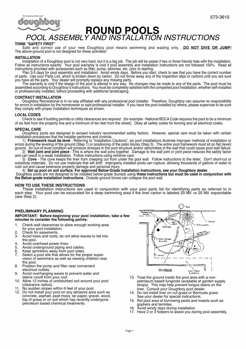
TOOLS AND MATERIALS REQUIREDMaterials Needed -• Nails - 2 1/2" Long (1 Doz.)• 12" x 12" x 2" patio blocks (Optional) - one per vertical• Ball of heavy string• Binder clips - 1 1/4" - 2" size (Available at stationary supply stores) - two per top rail • 2" x 4" board (See Step 1 for length)• Duct tape (2" wide)• Wood stake - 2" x 2" x 18"• Pool coving (See Step 12)• Enamel, fast drying (not lacquer)
Tools Required• 1/4" Drive ratchet with 3" extension (For the supplied 5/16" magnetic socket) - 10-1/2" resin pools only*Transit Required for 32' Pool• 2’ Carpenters level (Transit recommended)• Hammer• Flat end shovel• 5/16” Hex nut driver• 25’ Tape measure• Garden rake• Tamping tool• Roller (If available)• Screwdriver, flat end (Large)• 2 or 3 Garden hoses (Fill pool)• Felt tip marking pen• Carpenters saw• Sifting screen (To remove 1/8” pebbles and larger)• Sharp knife or single edge razor blade• Drill/Bit (See Step 1)• Small paint applicator (“Q-Tip”, cotton ball or match stick)
POOL FASTENER IDENTIFICATIONYour pool assembly may not require all the fasteners shown below. Refer to your Pool Parts list for the fasteners required to assemble your pool.
#10 x 1/2" SCREW 330-1127
#10 x 5/8" SCREW 330-1057
10-24 X 1/2" MACHINE SCREW
510-1008
10-24 SQUARE NUT 321-1025
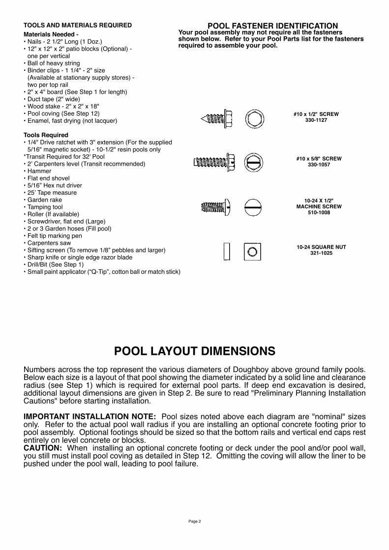
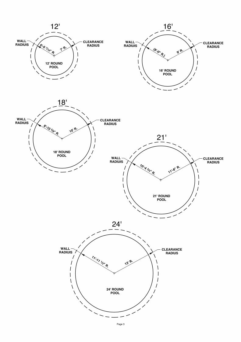
POOL LAYOUT DIMENSIONSNumbers across the top represent the various diameters of Doughboy above ground family pools. Below each size is a layout of that pool showing the diameter indicated by a solid line and clearance radius (see Step 1) which is required for external pool parts. If deep end excavation is desired, additional layout dimensions are given in Step 2. Be sure to read "Preliminary Planning Installation Cautions" before starting installation.
IMPORTANT INSTALLATION NOTE: Pool sizes noted above each diagram are "nominal" sizes only. Refer to the actual pool wall radius if you are installing an optional concrete footing prior to pool assembly. Optional footings should be sized so that the bottom rails and vertical end caps rest entirely on level concrete or blocks. CAUTION: When installing an optional concrete footing or deck under the pool and/or pool wall, you still must install pool coving as detailed in Step 12. Omitting the coving will allow the liner to be pushed under the pool wall, leading to pool failure.
18' ROUNDPOOL
10' R.
CLEARANCERADIUS8'-10 5/8" R.
WALL RADIUIS
Page 3
CLEARANCERADIUS
12' ROUNDPOOL
7' R.6'-0 7/16" R.
WALL RADIUIS CLEARANCE
RADIUS
16' ROUNDPOOL
9' R.(8'-0" R.)
WALL RADIUIS
18' ROUNDPOOL
10' R.
CLEARANCERADIUS8'-10 5/8" R.
WALL RADIUIS
CLEARANCERADIUS
21' ROUNDPOOL
11'-6" R.10'-4 3/4" R.
WALL RADIUIS
12' 16'
18'
21'
CLEARANCERADIUS
24' ROUNDPOOL
13' R.11'-11 1/2" R.
WALL RADIUIS
24'

Page 4
CLEARANCERADIUS
28' ROUNDPOOL
15' R.
13'-11 1/8" R.
WALL RADIUIS
CLEARANCERADIUS
32' ROUNDPOOL
17' R.16' R.
WALL RADIUIS
28'
32'
Page 5
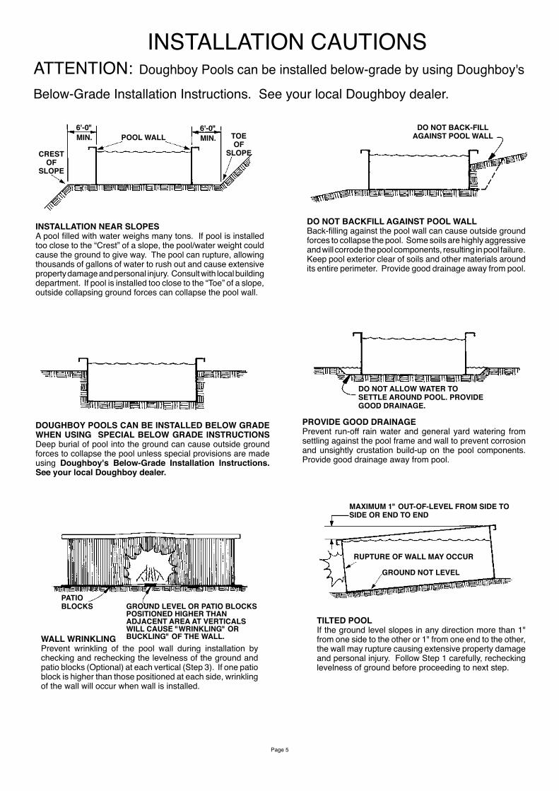
INSTALLATION CAUTIONSATTENTION: Doughboy Pools can be installed below-grade by using Doughboy's
Below-Grade Installation Instructions. See your local Doughboy dealer.
INSTALLATION NEAR SLOPESA pool filled with water weighs many tons. If pool is installed too close to the “Crest” of a slope, the pool/water weight could cause the ground to give way. The pool can rupture, allowing thousands of gallons of water to rush out and cause extensive property damage and personal injury. Consult with local building department. If pool is installed too close to the “Toe” of a slope, outside collapsing ground forces can collapse the pool wall.
MIN.6'-0"
POOL WALL MIN.6'-0"
CRESTOF
SLOPE
TOEOF
SLOPE
DO NOT BACK-FILLAGAINST POOL WALL
DO NOT BACKFILL AGAINST POOL WALLBack-filling against the pool wall can cause outside ground forces to collapse the pool. Some soils are highly aggressive and will corrode the pool components, resulting in pool failure. Keep pool exterior clear of soils and other materials around its entire perimeter. Provide good drainage away from pool.
DOUGHBOY POOLS CAN BE INSTALLED BELOW GRADE WHEN USING SPECIAL BELOW GRADE INSTRUCTIONS Deep burial of pool into the ground can cause outside ground forces to collapse the pool unless special provisions are made using Doughboy's Below-Grade Installation Instructions. See your local Doughboy dealer.
DO NOT ALLOW WATER TO SETTLE AROUND POOL. PROVIDE GOOD DRAINAGE.
PROVIDE GOOD DRAINAGEPrevent run-off rain water and general yard watering from settling against the pool frame and wall to prevent corrosion and unsightly crustation build-up on the pool components. Provide good drainage away from pool.
GROUND LEVEL OR PATIO BLOCKS POSITIONED HIGHER THAN ADJACENT AREA AT VERTICALS WILL CAUSE "WRINKLING" OR BUCKLING" OF THE WALL.
PATIOBLOCKS
WALL WRINKLINGPrevent wrinkling of the pool wall during installation by checking and rechecking the levelness of the ground and patio blocks (Optional) at each vertical (Step 3). If one patio block is higher than those positioned at each side, wrinkling of the wall will occur when wall is installed.
MAXIMUM 1" OUT-OF-LEVEL FROM SIDE TO SIDE OR END TO END
RUPTURE OF WALL MAY OCCUR
GROUND NOT LEVEL
TILTED POOLIf the ground level slopes in any direction more than 1" from one side to the other or 1" from one end to the other, the wall may rupture causing extensive property damage and personal injury. Follow Step 1 carefully, rechecking levelness of ground before proceeding to next step.
Page 6
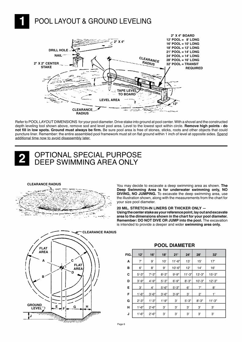
1 POOL LAYOUT & GROUND LEVELING 2" X 4" BOARD12' POOL = 8' LONG16' POOL = 10' LONG18' POOL = 12' LONG21' POOL = 14' LONG24' POOL = 14' LONG28' POOL = 16' LONG32' POOL = TRANSIT REQUIRED
CLEARANCERADIUS
DRILL HOLENAIL
2" X 2" CENTER STAKE
2" X 4"
LEVEL AREA
TAPE LEVELTO BOARD
CLEARANCE RADIUS
12"
Refer to POOL LAYOUT DIMENSIONS for your pool diameter. Drive stake into ground at pool center. With a shovel and the constructed depth leveling tool shown above, remove sod and level pool area. Level to the lowest spot within circle. Remove high points - do not fill in low spots. Ground must always be firm. Be sure pool area is free of stones, sticks, roots and other objects that could puncture liner. Remember: the entire assembled pool framework must sit on flat ground within 1 inch of level at opposite sides. Spend additional time now to avoid disassembly later.
2 OPTIONAL SPECIAL PURPOSE DEEP SWIMMING AREA ONLY
POOL DIAMETER
FIG. 12' 16' 18' 21' 24' 28' 32'
A 7' 9' 10' 11'-6" 13' 15' 17'
B 6' 8' 9' 10'-6" 12' 14' 16'
C 5'-3" 7'-3" 8'-3" 9'-9" 11'-3" 13'-3" 15'-3"
D 3'-9" 4'-9" 5'-3" 6'-9" 8'-3" 10'-3" 12'-3"
E 3' 4' 5'-6" 5'-3" 6' 7' 8'
F 1'-6" 3'-6" 3'-6" 3'-9" 3' 2' 1'
G 2'-3" 1'-3" 1'-9" 3' 5'-3" 8'-3" 11'-3"
H 1'-6" 2'-6" 3' 3' 3' 3' 3'
J 1'-6" 2'-6" 3' 3' 3' 3' 3'
CLEARANCE RADIUS You may decide to excavate a deep swimming area as shown. The Deep Swimming Area is for underwater swimming only, NO DIVING, NO JUMPING. To excavate the deep swimming area, use the illustration shown, along with the measurements from the chart for your size pool diameter.20 MIL. STRETCH-IN LINERS OR THICKER ONLY —Using the center stake as your reference point, lay out and excavate area to the dimensions shown in the chart for your pool diameter. Remember: DO NOT DIVE OR JUMP into the pool. The excavation is intended to provide a deeper and wider swimming area only.
CLEARANCE RADIUS
FLATAREA
A
B
C
D
FLATAREA
GROUNDLEVEL E F G H
J
Page 7
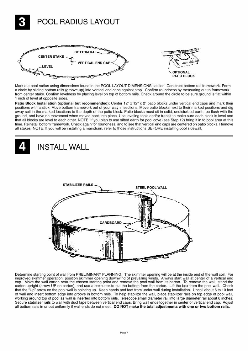
3 POOL RADIUS LAYOUT
OPTIONALPATIO BLOCK
CENTER STAKEBOTTOM RAIL
VERTICAL END CAPLEVEL
Mark out pool radius using dimensions found in the POOL LAYOUT DIMENSIONS section. Construct bottom rail framework. Form a circle by sliding bottom rails (groove up) into vertical end caps against stop. Confirm roundness by measuring out to framework from center stake. Confirm levelness by placing level on top of bottom rails. Check around the circle to be sure ground is flat within 1 inch of level at opposite sides. Patio Block Installation (optional but recommended): Center 12" x 12" x 2" patio blocks under vertical end caps and mark their positions with a stick. Move bottom framework out of your way in sections. Move patio blocks next to their marked positions and dig away soil in the marked locations to the depth of the patio block. Patio blocks must sit in solid, undisturbed earth, be flush with the ground, and have no movement when moved back into place. Use leveling tools and/or transit to make sure each block is level and that all blocks are level to each other. NOTE: If you plan to use sifted earth for pool cove (see Step 12) bring it in to pool area at this time. Reinstall bottom framework. Check again for roundness, and to see that vertical end caps are centered on patio blocks. Remove all stakes. NOTE: If you will be installing a maindrain, refer to those instructions BEFORE installing pool sidewall.
4 INSTALL WALL
STABILIZER RAILSSTEEL POOL WALL
CARDBOARD
Determine starting point of wall from PRELIMINARY PLANNING. The skimmer opening will be at the inside end of the wall coil. For improved skimmer operation, position skimmer opening downwind of prevailing winds. Always start wall at center of a vertical end cap. Move the wall carton near the chosen starting point and remove the pool wall from its carton. To remove the wall, stand the carton upright (arrow UP on carton), and use a boxcutter to cut the bottom from the carton. Lift the box from the pool wall. Check that the “Up” arrow on the pool wall is pointing up. Keep hands and feet from under wall during installation. Uncoil about 6 to 10 feet of wall and insert bottom edge into groove in bottom rails. To help stabilize the wall, place stabilizer rails on top edge of pool wall, working around top of pool as wall is inserted into bottom rails. Telescope small diameter rail into large diameter rail about 6 inches. Secure stabilizer rails to wall with duct tape between vertical end caps. Bring wall ends together in center of vertical end cap. Adjust all bottom rails in or out uniformly if wall ends do not meet. DO NOT make the total adjustments with one or two bottom rails.

Page 8
5 INSTALL WALL JOINT
�
REMOVE STABILIZER RAILS
TO APPROX. THIS POINT
JOINT PIECE
ALIGN FORMED HOOKS
JOINT PIECE
Bring wall ends together in center of vertical end cap. Adjust all bottom rails in or out uniformly if wall ends do not meet. DO NOT make the total adjustments with one or two bottom rails. Remove stabilizer rails in the areas shown above. Move pool wall ends together inside the pool. Align formed hooks on wall ends and slide on joint piece(s) until the top is even with top of formed wall hooks. WARNING: Do not hammer joint piece on! Damaged hooks or joint piece can lead to pool wall failure. Manufacturer cannot assume responsibility for performance of this product if the joint piece has been improperly installed by forcing it on in any manner. If joint piece does not slide on easily, realign sidewall hooks. Use ordinary dishwashing liquid for lubrication. When joint piece is in place, replace wall into bottom rails and reinstall stabilizer rails.
6 COAT OPENINGS
Matching pool wall cover plates are provided with pools that have two skimmer openings. Tape over the extra skimmer and return opening in the event you are only using one skimmer. Use a “Q-Tip” or cotton ball dipped in fast drying enamel to coat all bare metal edges of skimmer opening, return opening and mounting holes. This coating protects edges against corrosion. DO NOT use fingers as sharp edges may cause serious cuts. Enamel must dry prior to installing liner to prevent damage to liner in contact with freshly painted surfaces.
EXTRA SKIMMER OPENING
VIEW INSIDE OF POOL VIEW INSIDE OF POOL
EXTRA INLET HOLE
DUCT TAPE
7 INSTALL VERTICALS
VERTICALS
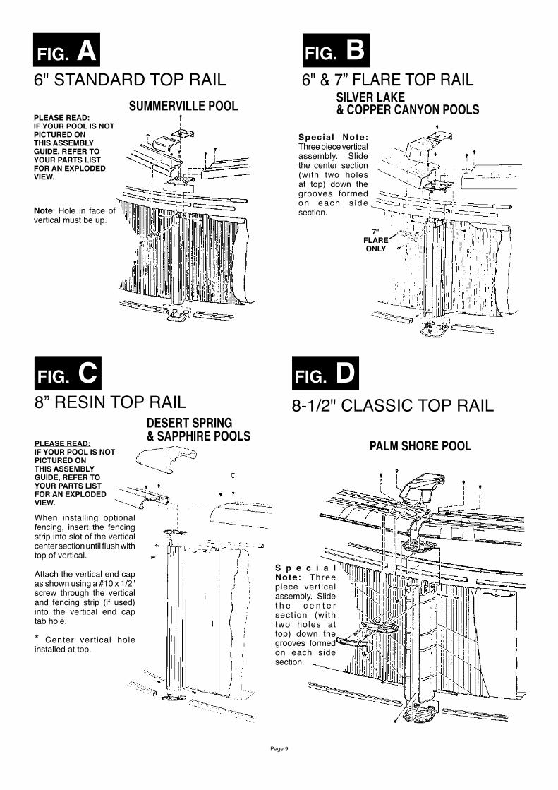
Carefully follow the details shown in Fig.s A, B, C, D, or E to assemble verticals to the pool wall. Refer to your pool parts list for parts identification and use all necessary hardware. Check pool for roundness by measuring across the pool from side to side. Pool diameter should be the same from point to point.
Page 9
PLEASE READ:IF YOUR POOL IS NOT PICTURED ON THIS ASSEMBLY GUIDE, REFER TOYOUR PARTS LIST FOR AN EXPLODED VIEW.
FIG. A6" STANDARD TOP RAIL
SUMMERVILLE POOL
Note: Hole in face of vertical must be up.
FIG. B6" & 7” FLARE TOP RAIL
SILVER LAKE& COPPER CANYON POOLS
7" FLAREONLY
Specia l Note: Three piece vertical assembly. Slide the center section (with two holes at top) down the grooves formed on each s i de section.
FIG. CDESERT SPRING & SAPPHIRE POOLS
When installing optional fencing, insert the fencing strip into slot of the vertical center section until flush with top of vertical.
Attach the vertical end cap as shown using a #10 x 1/2" screw through the vertical and fencing strip (if used) into the vertical end cap tab hole.
* Center vertical hole installed at top.
FIG. D
PLEASE READ:IF YOUR POOL IS NOT PICTURED ON THIS ASSEMBLY GUIDE, REFER TOYOUR PARTS LIST FOR AN EXPLODED VIEW.
S p e c i a l Note: Three piece vertical assembly. Slide t h e c e n t e r sect ion (wi th two holes at top) down the grooves formed on each side section.
8-1/2" CLASSIC TOP RAIL
PALM SHORE POOL
8” RESIN TOP RAIL
Page 10
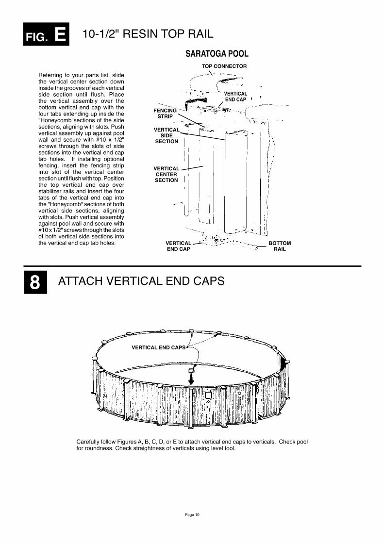
FIG. E 10-1/2" RESIN TOP RAILSARATOGA POOL
Referring to your parts list, slide the vertical center section down inside the grooves of each vertical side section until flush. Place the vertical assembly over the bottom vertical end cap with the four tabs extending up inside the "Honeycomb"sections of the side sections, aligning with slots. Push vertical assembly up against pool wall and secure with #10 x 1/2" screws through the slots of side sections into the vertical end cap tab holes. If installing optional fencing, insert the fencing strip into slot of the vertical center section until flush with top. Position the top vertical end cap over stabilizer rails and insert the four tabs of the vertical end cap into the "Honeycomb" sections of both vertical side sections, aligning with slots. Push vertical assembly against pool wall and secure with #10 x 1/2" screws through the slots of both vertical side sections into the vertical end cap tab holes.
TOP CONNECTOR
VERTICAL END CAP
FENCING STRIP
VERTICAL SIDE
SECTION
VERTICAL CENTER SECTION
VERTICAL END CAP
BOTTOM RAIL
8 ATTACH VERTICAL END CAPS
VERTICAL END CAPS
Carefully follow Figures A, B, C, D, or E to attach vertical end caps to verticals. Check pool for roundness. Check straightness of verticals using level tool.
Page 11
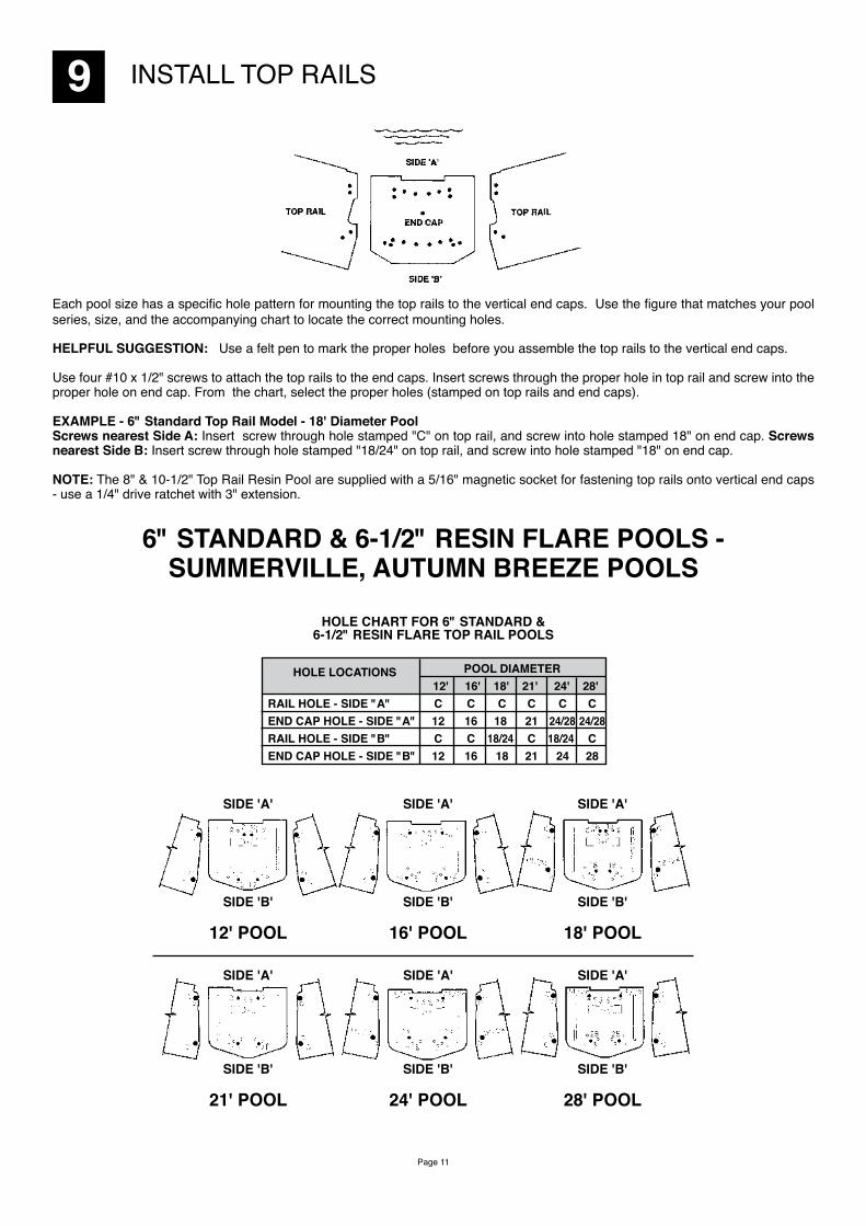
9 INSTALL TOP RAILS
Each pool size has a specific hole pattern for mounting the top rails to the vertical end caps. Use the figure that matches your pool series, size, and the accompanying chart to locate the correct mounting holes.
HELPFUL SUGGESTION: Use a felt pen to mark the proper holes before you assemble the top rails to the vertical end caps.
Use four #10 x 1/2" screws to attach the top rails to the end caps. Insert screws through the proper hole in top rail and screw into the proper hole on end cap. From the chart, select the proper holes (stamped on top rails and end caps).
EXAMPLE - 6" Standard Top Rail Model - 18' Diameter PoolScrews nearest Side A: Insert screw through hole stamped "C" on top rail, and screw into hole stamped 18" on end cap. Screws nearest Side B: Insert screw through hole stamped "18/24" on top rail, and screw into hole stamped "18" on end cap.
NOTE: The 8" & 10-1/2" Top Rail Resin Pool are supplied with a 5/16" magnetic socket for fastening top rails onto vertical end caps - use a 1/4" drive ratchet with 3" extension.
6" STANDARD & 6-1/2" RESIN FLARE POOLS - SUMMERVILLE, AUTUMN BREEZE POOLS
HOLE CHART FOR 6" STANDARD & 6-1/2" RESIN FLARE TOP RAIL POOLS
HOLE LOCATIONS POOL DIAMETER 12' 16' 18' 21' 24' 28' RAIL HOLE - SIDE "A" C C C C C C END CAP HOLE - SIDE "A" 12 16 18 21 24/28 24/28 RAIL HOLE - SIDE "B" C C 18/24 C 18/24 C END CAP HOLE - SIDE "B" 12 16 18 21 24 28
SIDE 'B'
12' POOL
SIDE 'B'
16' POOL
SIDE 'B'
18' POOL
SIDE 'B'
21' POOL
SIDE 'B'
24' POOL
SIDE 'B'
28' POOL
SIDE 'A' SIDE 'A' SIDE 'A'
SIDE 'A' SIDE 'A' SIDE 'A'
Page 12
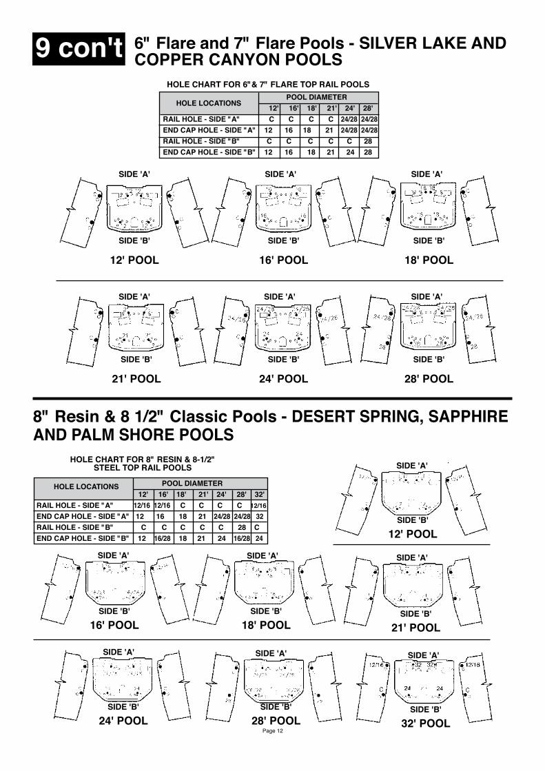
6" Flare and 7" Flare Pools - SILVER LAKE AND COPPER CANYON POOLS
POOL DIAMETER 12' 16' 18' 21' 24' 28' RAIL HOLE - SIDE "A" C C C C 24/28 24/28 END CAP HOLE - SIDE "A" 12 16 18 21 24/28 24/28 RAIL HOLE - SIDE "B" C C C C C 28 END CAP HOLE - SIDE "B" 12 16 18 21 24 28
HOLE LOCATIONS
HOLE CHART FOR 6"& 7" FLARE TOP RAIL POOLS
SIDE 'A' SIDE 'A' SIDE 'A'
SIDE 'A' SIDE 'A' SIDE 'A'
SIDE 'B'
12' POOL
SIDE 'B'
16' POOL
SIDE 'B'
18' POOL
SIDE 'B'
21' POOL
SIDE 'B'
24' POOL
SIDE 'B'
28' POOL
9 con't
8" Resin & 8 1/2" Classic Pools - DESERT SPRING, SAPPHIREAND PALM SHORE POOLS
HOLE LOCATIONS POOL DIAMETER 12' 16' 18' 21' 24' 28' 32' RAIL HOLE - SIDE "A" 12/16 12/16 C C C C 12/16 END CAP HOLE - SIDE "A" 12 16 18 21 24/28 24/28 32 RAIL HOLE - SIDE "B" C C C C C 28 C END CAP HOLE - SIDE "B" 12 16/28 18 21 24 16/28 24
HOLE CHART FOR 8" RESIN & 8-1/2" STEEL TOP RAIL POOLS SIDE 'A'
SIDE 'A'
SIDE 'A'
SIDE 'A'
SIDE 'A' SIDE 'A'
SIDE 'A'
SIDE 'B' 12' POOL
SIDE 'B' 16' POOL
SIDE 'B' 18' POOL
SIDE 'B' 21' POOL
SIDE 'B'
24' POOLSIDE 'B'
28' POOLSIDE 'B'
32' POOL
Page 13
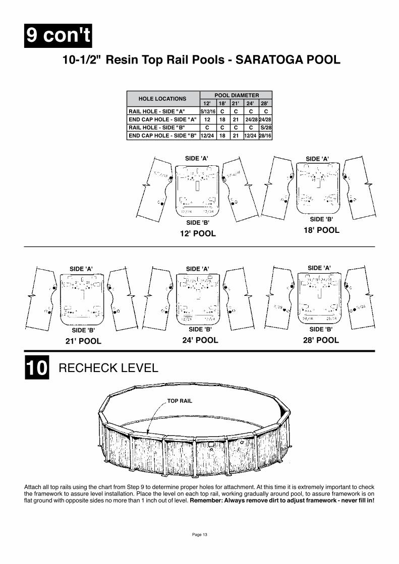
10-1/2" Resin Top Rail Pools - SARATOGA POOL
9 con't
POOL DIAMETER 12' 18' 21' 24' 28' RAIL HOLE - SIDE "A" S/12/16 C C C C END CAP HOLE - SIDE "A" 12 18 21 24/28 24/28 RAIL HOLE - SIDE "B" C C C C S/28 END CAP HOLE - SIDE "B" 12/24 18 21 12/24 28/16
HOLE LOCATIONS
SIDE 'A' SIDE 'A'
SIDE 'A' SIDE 'A' SIDE 'A'
SIDE 'B'
18' POOLSIDE 'B'
12' POOL
SIDE 'B'
21' POOLSIDE 'B'
24' POOLSIDE 'B'
28' POOL
10 RECHECK LEVEL
TOP RAIL
Attach all top rails using the chart from Step 9 to determine proper holes for attachment. At this time it is extremely important to check the framework to assure level installation. Place the level on each top rail, working gradually around pool, to assure framework is on flat ground with opposite sides no more than 1 inch out of level. Remember: Always remove dirt to adjust framework - never fill in!
Page 14
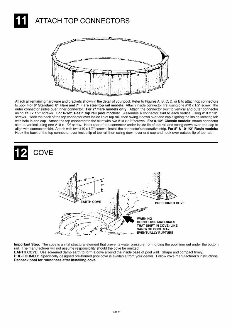
11 ATTACH TOP CONNECTORS
Attach all remaining hardware and brackets shown in the detail of your pool. Refer to Figures A, B, C, D, or E to attach top connectors to pool. For 6" Standard, 6" Flare and 7" Flare steel top rail models: Attach inside connector first using one #10 x 1/2" screw. The outer connector slides over inner connector. For 7" flare models only: Attach the connector skirt to vertical and outer connector using #10 x 1/2" screws. For 6-1/2" Resin top rail pool models: Assemble a connector skirt to each vertical using #10 x 1/2" screws. Hook the back of the top connector over inside lip of top rail, then swing it down over end cap aligning the inside locating tab with hole in end cap. Attach the top connector to the skirt with two #10 x 5/8"screws. For 8-1/2" Classic models: Attach connector skirt to vertical using one #10 x 1/2" screw. Hook rear of top connector under inside lip of top rail and swing down over end cap to align with connector skirt. Attach with two #10 x 1/2" screws. Install the connector's decorative strip. For 8" & 10-1/2" Resin models: Hook the back of the top connector over inside lip of top rail then swing down over end cap and hook over outside lip of top rail.
12 COVE
Important Step: The cove is a vital structural element that prevents water pressure from forcing the pool liner out under the bottom rail. The manufacturer will not assume responsibility should the cove be omitted. EARTH COVE: Use screened damp earth to form a cove around the inside base of pool wall. Shape and compact firmly. PRE-FORMED: Specifically designed pre-formed pool cove is available from your dealer. Follow cove manufacturer’s instructions. Recheck pool for roundness after installing cove.
WARNINGDO NOT USE MATERIALS THAT SHIFT IN COVE (LIKE SAND) OR POOL MAY EVENTUALLY RUPTURE
EARTH COVE
6"4"
PREFORMED COVE
Page 15
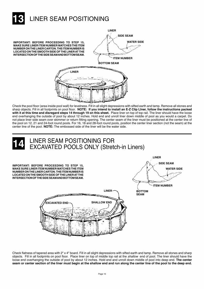
13 LINER SEAM POSITIONING
IMPORTANT: BEFORE PROCEEDING TO STEP 15, MAKE SURE LINER ITEM NUMBER MATCHES THE ITEM NUMBER ON THE LINER CARTON. THE ITEM NUMBER IS LOCATED ON THE SMOOTH SIDE OF THE LINER AT THE INTERSECTION OF THE SIDE SEAM AND BOTTOM SEAM.
LINER
SIDE SEAM
WATER SIDE
ITEM NUMBER
BOTTOM SEAM
LINER
Check the pool floor (area inside pool wall) for levelness. Fill in all slight depressions with sifted earth and tamp. Remove all stones and sharp objects. Fill in all footprints on pool floor. NOTE: If you intend to install an E-Z Clip LIner, follow the instructions packed with it at this time and disregard steps 14 through 19 on this sheet. Place liner on top of top rail. The liner should have the loose end overhanging the outside of pool by about 12 inches. Hold end and unroll liner down middle of pool as you would a carpet. Do not place liner side seam over skimmer or return fitting opening. The center seam of the liner must be positioned at the center line of the pool on 12, 21 and 24-foot round pools. For 16, 18 and 28-foot round pools, position the center liner section (not the seam) at the center line of the pool. NOTE: The embossed side of the liner will be the water side.
14 LINER SEAM POSITIONING FOREXCAVATED POOLS ONLY (Stretch-in Liners)
IMPORTANT: BEFORE PROCEEDING TO STEP 15, MAKE SURE LINER ITEM NUMBER MATCHES THE ITEM NUMBER ON THE LINER CARTON. THE ITEM NUMBER IS LOCATED ON THE SMOOTH SIDE OF THE LINER AT THE INTERSECTION OF THE SIDE SEAM AND BOTTOM SEAM.
Check flatness of tapered area with 2" x 4" board. Fill in all slight depressions with sifted earth and tamp. Remove all stones and sharp objects. Fill in all footprints on pool floor. Place liner on top of middle top rail at the shallow end of pool. The liner should have the loose end overhanging the outside of pool by about 12 inches. Hold end and unroll down middle of pool into deep end. The center seam or center section of the liner must begin at the shallow end and run along the center line of the pool to the deep end.
SIDE SEAM
LINER
WATER SIDE
ITEM NUMBER
BOTTOM SEAM
LINER
SHALLOW ENDEXCAVATED END
Page 16
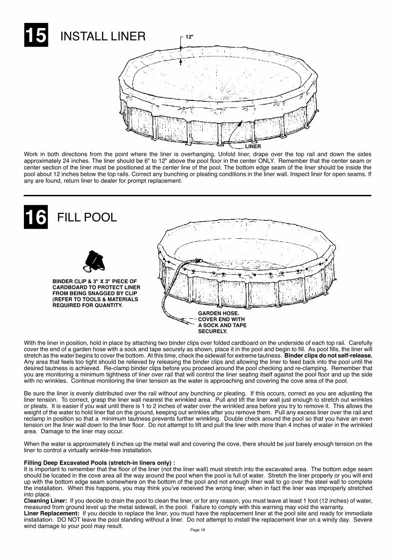
15 INSTALL LINER 12"
LINERWork in both directions from the point where the liner is overhanging. Unfold liner, drape over the top rail and down the sides approximately 24 inches. The liner should be 6" to 12" above the pool floor in the center ONLY. Remember that the center seam or center section of the liner must be positioned at the center line of the pool. The bottom edge seam of the liner should be inside the pool about 12 inches below the top rails. Correct any bunching or pleating conditions in the liner wall. Inspect liner for open seams. If any are found, return liner to dealer for prompt replacement.
16 FILL POOL
BINDER CLIP & 3" X 3" PIECE OF CARDBOARD TO PROTECT LINER FROM BEING SNAGGED BY CLIP (REFER TO TOOLS & MATERIALS REQUIRED FOR QUANTITY.
GARDEN HOSE.COVER END WITH A SOCK AND TAPE SECURELY.
With the liner in position, hold in place by attaching two binder clips over folded cardboard on the underside of each top rail. Carefully cover the end of a garden hose with a sock and tape securely as shown, place it in the pool and begin to fill. As pool fills, the liner will stretch as the water begins to cover the bottom. At this time, check the sidewall for extreme tautness. Binder clips do not self-release. Any area that feels too tight should be relieved by releasing the binder clips and allowing the liner to feed back into the pool until the desired tautness is achieved. Re-clamp binder clips before you proceed around the pool checking and re-clamping. Remember that you are monitoring a minimum tightness of liner over rail that will control the liner seating itself against the pool floor and up the side with no wrinkles. Continue monitoring the liner tension as the water is approaching and covering the cove area of the pool.
Be sure the liner is evenly distributed over the rail without any bunching or pleating. If this occurs, correct as you are adjusting the liner tension. To correct, grasp the liner wall nearest the wrinkled area. Pull and lift the liner wall just enough to stretch out wrinkles or pleats. It is easier if you wait until there is 1 to 2 inches of water over the wrinkled area before you try to remove it. This allows the weight of the water to hold liner flat on the ground, keeping out wrinkles after you remove them. Pull any excess liner over the rail and reclamp in position so that a minimum tautness prevents further wrinkling. Double check around the pool so that you have an even tension on the liner wall down to the liner floor. Do not attempt to lift and pull the liner with more than 4 inches of water in the wrinkled area. Damage to the liner may occur.
When the water is approximately 6 inches up the metal wall and covering the cove, there should be just barely enough tension on the liner to control a virtually wrinkle-free installation.
Filling Deep Excavated Pools (stretch-in liners only) :It is important to remember that the floor of the liner (not the liner wall) must stretch into the excavated area. The bottom edge seam should be located in the cove area all the way around the pool when the pool is full of water. Stretch the liner properly or you will end up with the bottom edge seam somewhere on the bottom of the pool and not enough liner wall to go over the steel wall to complete the installation. When this happens, you may think you’ve received the wrong liner, when in fact the liner was improperly stretched into place.Cleaning Liner: If you decide to drain the pool to clean the liner, or for any reason, you must leave at least 1 foot (12 inches) of water, measured from ground level up the metal sidewall, in the pool. Failure to comply with this warning may void the warranty.Liner Replacement: If you decide to replace the liner, you must have the replacement liner at the pool site and ready for immediate installation. DO NOT leave the pool standing without a liner. Do not attempt to install the replacement liner on a windy day. Severe wind damage to your pool may result.
Page 17
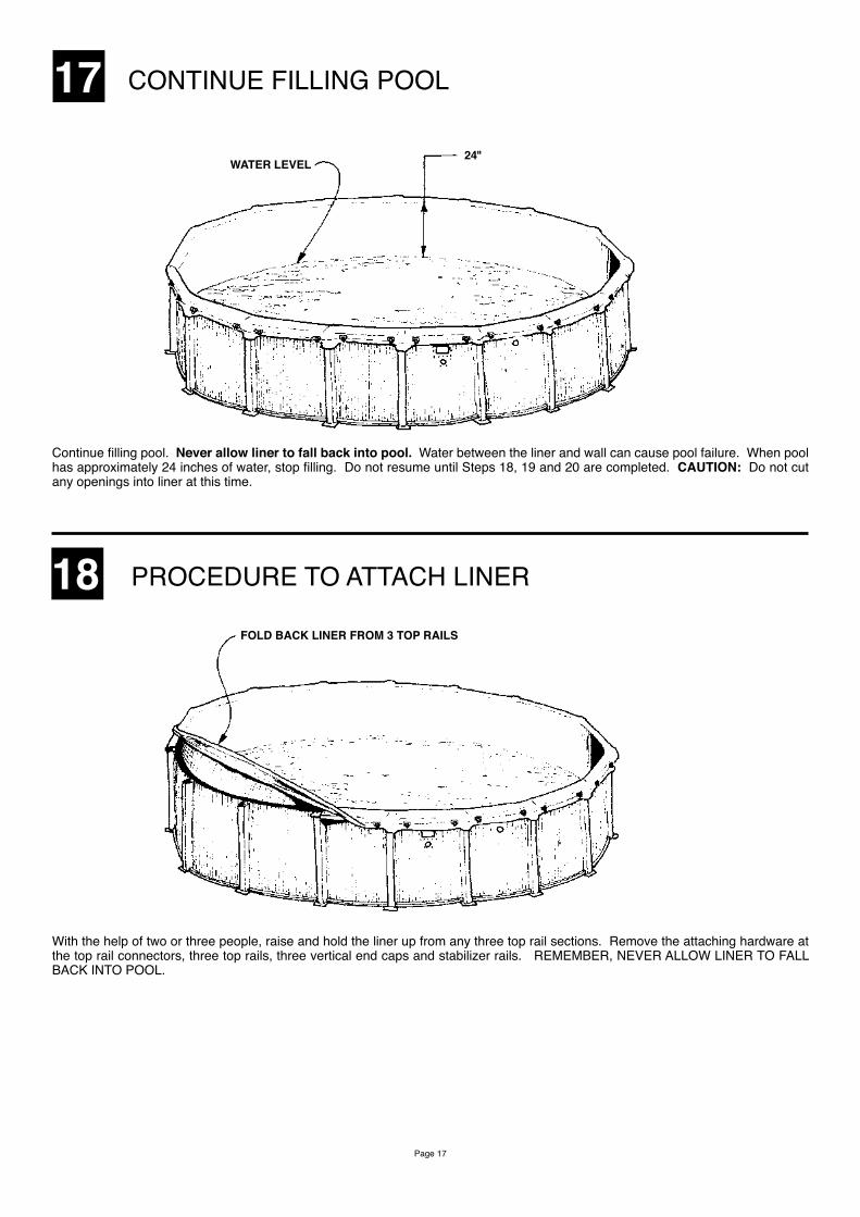
17 CONTINUE FILLING POOL
24"WATER LEVEL
Continue filling pool. Never allow liner to fall back into pool. Water between the liner and wall can cause pool failure. When pool has approximately 24 inches of water, stop filling. Do not resume until Steps 18, 19 and 20 are completed. CAUTION: Do not cut any openings into liner at this time.
18 PROCEDURE TO ATTACH LINER
FOLD BACK LINER FROM 3 TOP RAILS
With the help of two or three people, raise and hold the liner up from any three top rail sections. Remove the attaching hardware at the top rail connectors, three top rails, three vertical end caps and stabilizer rails. REMEMBER, NEVER ALLOW LINER TO FALL BACK INTO POOL.
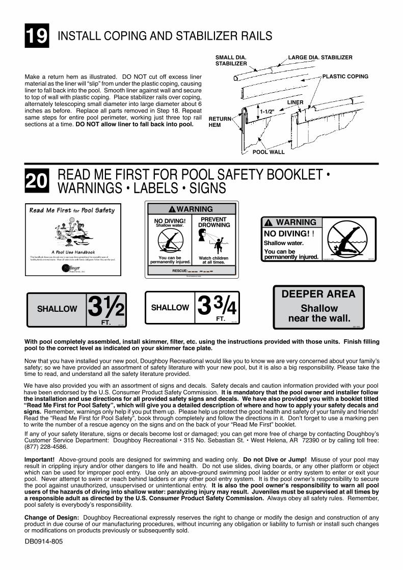
19 INSTALL COPING AND STABILIZER RAILS
Make a return hem as illustrated. DO NOT cut off excess liner material as the liner will “slip” from under the plastic coping, causing liner to fall back into the pool. Smooth liner against wall and secure to top of wall with plastic coping. Place stabilizer rails over coping, alternately telescoping small diameter into large diameter about 6 inches as before. Replace all parts removed in Step 18. Repeat same steps for entire pool perimeter, working just three top rail sections at a time. DO NOT allow liner to fall back into pool.
LARGE DIA. STABILIZERSMALL DIA. STABILIZER
PLASTIC COPING
1-1/2"LINER
RETURNHEM
POOL WALL
READ ME FIRST FOR POOL SAFETY BOOKLET • WARNINGS • LABELS • SIGNS20
With pool completely assembled, install skimmer, filter, etc. using the instructions provided with those units. Finish filling pool to the correct level as indicated on your skimmer face plate.
Now that you have installed your new pool, Doughboy Recreational would like you to know we are very concerned about your family’s safety; so we have provided an assortment of safety literature with your new pool, but it is also a big responsibility. Please take the time to read, and understand all the safety literature provided.
We have also provided you with an assortment of signs and decals. Safety decals and caution information provided with your pool have been endorsed by the U.S. Consumer Product Safety Commission. It is mandatory that the pool owner and installer follow the installation and use directions for all provided safety signs and decals. We have also provided you with a booklet titled “Read Me First for Pool Safety”, which will give you a detailed description of where and how to apply your safety decals and signs. Remember, warnings only help if you put them up. Please help us protect the good health and safety of your family and friends! Read the “Read Me First for Pool Safety”, book through completely and follow the directions in it. Don’t forget to use a marking pen to write the number of a rescue agency on the signs and on the back of your “Read Me First” booklet.If any of your safety literature, signs or decals become lost or damaged; you can get more free of charge by contacting Doughboy’s Customer Service Department: Doughboy Recreational • 315 No. Sebastian St. • West Helena, AR 72390 or by calling toll free: (877) 228-4586.
Important! Above-ground pools are designed for swimming and wading only. Do not Dive or Jump! Misuse of your pool may result in crippling injury and/or other dangers to life and health. Do not use slides, diving boards, or any other platform or object which can be used for improper pool entry. Use only an above-ground swimming pool ladder or entry system to enter or exit your pool. Never attempt to swim or reach behind ladders or any other pool entry system. It is the pool owner’s responsibility to secure the pool against unauthorized, unsupervised or unintentional entry. It is also the pool owner’s responsibility to warn all pool users of the hazards of diving into shallow water: paralyzing injury may result. Juveniles must be supervised at all times by a responsible adult as directed by the U.S. Consumer Product Safety Commission. Always obey all safety rules. Remember, pool safety is everybody’s responsibility.
Change of Design: Doughboy Recreational expressly reserves the right to change or modify the design and construction of any product in due course of our manufacturing procedures, without incurring any obligation or liability to furnish or install such changes or modifications on products previously or subsequently sold.
DEEPER AREAShallow
near the wall.560-1042
NO DIVING! !Shallow water.You can bepermanently injured. Copyright © 1989 560-1041
WARNING
FT.
SHALLOW560-1043
312
PREVENTDROWNING
Watch children at all times.
You can be permanently injured.
Shallow water.
WARNING
Do not remove or cover. RESCUE:
NO DIVING!
SHALLOW560-1056
33/4FT.
DB0914-805