“TC” - SMW AUTOBLOK › documentos › TC.pdfModular clamping equipment “TC ... We use the...
16
Modular clamping equipment “TC”range and accessories TCt pag. 2. 6 TCt-XL pag. 2. 8 DCS-TCt pag. 2. 9 Extension element TCt pag. 2. 12 Complete extension element TCt pag. 2. 13 TCg pag. 2. 7 Double support with jaws TC pag. 2. 13 Base with fixed support TCt pag. 2. 14 Base with double support whit jaws pag. 2. 14 MVS-TCt pag. 2. 16 VCS-TCt pag. 2. 18 Accessories TC pag. 2. 21 DVCS-TCt pag. 2. 19 Spare parts TC pag. 2. 25 2 . 1 2
Transcript of “TC” - SMW AUTOBLOK › documentos › TC.pdfModular clamping equipment “TC ... We use the...

Modular clamping equipment “TC”range and accessories
TCtpag. 2. 6
TCt-XLpag. 2. 8
DCS-TCtpag. 2. 9
Extensionelement TCt pag. 2. 12
Completeextensionelement TCt pag. 2. 13
TCgpag. 2. 7
Double supportwith jaws TC pag. 2. 13
Base with fixedsupport TCt pag. 2. 14
Base withdouble supportwhit jaws pag. 2. 14
MVS-TCtpag. 2. 16
VCS-TCtpag. 2. 18
Accessories TC pag. 2. 21
DVCS-TCtpag. 2. 19
Spare parts TC pag. 2. 25
2 . 1
2

Modular We use the true definition of the term modular; product which is composed of separate or separable ele-ments. With these separate or separable elements we can achieve many different clamping solutions.The only different component of these clamping solutions is the base.The base length determines the clamping capacity while all other components remain the same.Fixed and movable vise jaws can be used with any base configuration, offering the most flexible workholding solutions available.This modular system allows the user to realize the maximum number of workholding combinations with the minimum investment in equipment.
PrecisionAll sliding and joining surfaces are precision ground.Each item is thoroughly inspected and tested both before and after assembly.This rigid quality control allows us to offer the high tolerance levels shown on page 47.Alignment of the clamping equipment is ensured by using high tolerance ground keys.Other key dimensions are available upon request.The clamping jaws pull the workpiece down 0.2 mm. (0.008”) against the ground base for unmatched accuracy.
DurabilityAll components are constructed from oversize steel profiles ensuring the equipment is exceptionally sturdy and can provide the user with optimal performance.Wear parts are special treated to achieve a surface hardness of 50/60 HRC.All non-ground surfaces are burnished to protect against corrosion.
Quick-changeA patented system allows quick repositioning of the clamping jaws .The clamping jaw is lifted slightly from the base and shuttled to the next clamping position then lowered into place.Part changeovers and size changes can be made quickly and easely.
ReliableThe six bolts mounting the fixed jaw to the base provide the most rigid platform possible to support the clamped workpiece.
VersatilityThe fixed jaw has serrations on the rare face so that by reversing it, unmachined workpieces can be clamped.The movable jaw can be rigid or floating (for clamping on uneven surfaces).The interchangeability of the rigid slide-way with the floating slide-way ( both encluded as standard equip-ment) allows the user to clamp finished or raw workpieces.The standard CLAK system allows the quick-change of parallels, angular parallels, soft jaws and “V “jaws in order to machine any workpiece.
ManageableThe weight of 27 kg (59 lb.) for the 150 mm. x 200 mm. (6”x 8”) vise and simple clamping system allow for easy movement from one machine tool to another.
•
=
+• – =
+• – =
+• – =
+ – =
+• –
+• – =
+• Start Add Combine Remove Result– =
+• – =
Pag. 2.6 Pag. 2.12
Pag. 2.6 Pag. 2.13
Pag. 2.9 Pag. 2.26
Pag. 2.6 Pag. 2.21
Pag. 2.6 Pag. 2.17
Pag. 2.16
Pag. 2.6 Pag. 4.6
The advantages of modularityTC is...
2 . 2 2 . 3
2

Floating slide - way raw workpieces Rigid skide-way for finished workpieces
Work stop
Pull down jaws 0,02 mm CLAK fittingFixed support turned of 180°(grooved part)
Eye boltfor lifting)
Cover forprotectionthe screw
6 bolts forthe fixed support
Block for clamping screwwith threated anti-frictionbronze bushing
Grinding holes forthe clamping on agrid system TCg
Patended system forquick positioning
Wrench
jaws with threated holesfor a contrast prop
Parallels,Angulars parallels,soft jaws quick change
Cross keyfor T-slots M.T.
Torque wrench
Options:
Base
2 . 4 2 . 5
2

77 58 01 07 TCg 110 x 100 100
Cod. type
40 78 80 150 - 9 338 110 280 110 10 63 18 38 11,5
77 58 01 08 TCg 110 x 150 150 40 78 80 200 - 9 388 110 330 110 10 63 18 38 12,5
77 58 02 07 TCg 150 x 200 200 50 98 114 200 - 12,5 481 150 413 150 13 85 30 48 27
77 58 02 08 TCg 150 x 250 250 50 98 114 200 - 12,5 531 150 463 150 13 85 30 48 29
77 58 03 07 TCg 200 x 250 250 70 138 149 300 150 12,5 647 200 560 200 15,5 123 27 68 74
77 58 03 08 TCg 200 x 300 300 70 138 149 400 200 12,5 697 200 610 200 15,5 123 27 68 78
A B C D E F H I J L M N O P S Weightmm mm mm mm mm mm mm mm mm mm mm mm mm mm mm kg
O
D
PM
J
NS
C
B
ø H ø 16 H7F
EL
I
A
Clamping equipment TCg complete with wrench, work stop, rigid slide way, floating slide-way (for raw workpie-ce), pair of CLAK parallels, cover for the protection of the screw, eye bolt for lifting, wooden packing case.
* Other fixing and positioning holes dimensions upon request
TCgclamping equipment (for grid)
AO
C
B
G H7M
J
ø HP
D E F
NS
LI
Clamping equipment TCt complete with wrench, work stop, rigid slide way, floating slide-way (for raw work-piece), pair of positioning keys, pair of CLAK parallels, cover for the protection of the screw, eye bolt for lifting, wooden packing case.
77 58 01 01 TCt 110 x 100 100
Cod. type
40 78 80 150 - 12 9 338 110 280 110 10 63 18 38 11,5
77 58 01 02 TCt 110 x 150 150 40 78 80 100 100 12 9 388 110 330 110 10 63 18 38 12,5
77 58 02 01 TCt 150 x 200 200 50 98 114 200 - 18 12,5 481 150 413 150 13 85 30 48 27
77 58 02 02 TCt 150 x 250 250 50 98 114 100 150 18 12,5 531 150 463 150 13 85 30 48 29
77 58 02 03 TCt 150 x 300 300 50 98 114 100 100 18 12,5 588 150 520 150 13 85 30 48 31,5
77 58 03 01 TCt 200 x 250 250 70 138 149 150 150 18 12,5 647 200 560 200 15,5 123 27 68 74
77 58 03 02
77 58 03 03
TCt 200 x 300 300 70 138 149 200 200 18 12,5 697 200 610 200 15,5 123 27 68 78
A B C D E F G H I J L M N O P S Weightmm mm mm mm mm mm mm mm mm mm mm mm mm mm mm mm kg
TCt 200 x 400 400 70 138 149 150 150 18 12,5 797 200 710 200 15,5 123 27 68 86
TCt clamping equipment (for T slots)
2 . 6 2 . 7
2

J
MG H7øHG H7
F E D D E FLI
A T A
B
C
NS
+• – =
77 58 11 01
77 58 11 02
77 58 12 01
77 58 12 02
77 58 13 01
77 58 13 02
DCS-TCt 110 x 130 130
Cod. for type
40 78 80 150 - 12 9 676 110 560 110 10 38 22
DCS-TCt 110 x 180 180 40 78 80 100 100 12 9 776 110 660 110 10 38 24
DCS-TCt 150 x 230 230 50 98 116 200 - 18 12,5 966 150 830 150 13 48 52
DCS-TCt 150 x 280 280 50 98 116 100 150 18 12,5 1066 150 930 150 13 48 56
DCS-TCt 200 x 280 280 70 138 150 150 150 18 12,5 1294 200 1122 200 15,5 68 136
DCS-TCt 200 x 330 330 70 138 150 200 200 18 12,5 1394 200 1222 200 15,5 68 144
A B C D E F G H I J L M N S Weightmm mm mm mm mm mm mm mm mm mm mm mm mm mm kg
80
80
108
108
194
194
Tmm
Double clamping equipment DCS-TCt complete with:1 wrench, 2 work stops, 2 rigid slide-ways, 2 floating slide-ways (for raw workpiece), 1 pair of positioning keys, 2 pair of CLAK parallels, 2 covers for the protection of the screw, 2 eye bolts for lifting, wooden packing case.
Double clamping equipment DCS-TCt
Working examples:
The modularity of the system combined withsome other components offers many additional clamping solutions.
A
PD
L
B
I
O
C
F F M
J
G H7 NS
E EG H7 ø H
77 58 01 04 TCt-XL 110 x 425 425
Cod. type
77 58 02 04 TCt-XL 150 x 545 545
77 58 02 05 TCt-XL 150 x 665 665
Amm
40
50
50
Bmm
78
98
98
Cmm
300
379
439
Dmm
100
100
100
Emm
100
150
200
Fmm
12
18
18
Gmm
9
12,5
12,5
Hmm
658
825
946
Imm
110
150
150
Jmm
600
758
878
Lmm
110
150
150
Mmm
10
13
13
Nmm
63
85
85
Omm
238
295
355
Pmm
38
48
48
Smm
18,2
40
44,7
Weightkg
clamping equipment (for T slots)TCt - XL
Clamping equipment TCt-XL, complete with wrench, work stop, rigid slide-way, floating slide-way (for raw wor-kpiece), pair of positioning keys, pair of CLAK parallels, cover for the protection of the screw, eye bolt for lifting, wooden packing case.
2 . 8 2 . 9
2
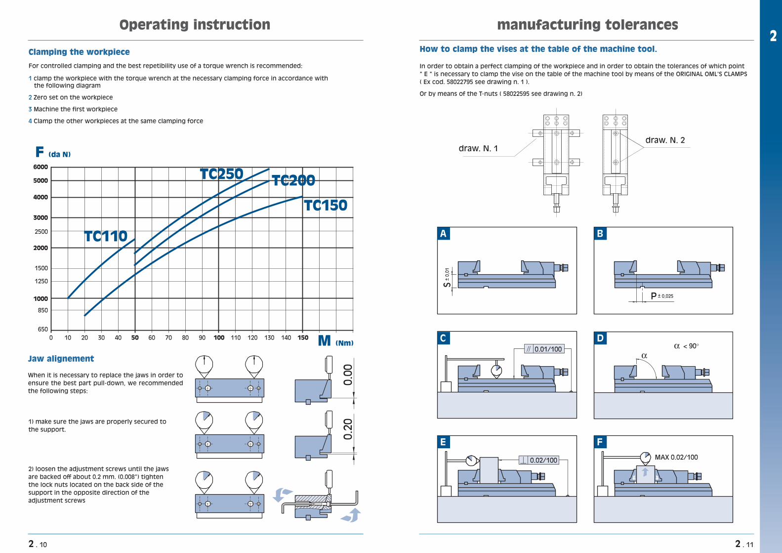
How to clamp the vises at the table of the machine tool.
In order to obtain a perfect clamping of the workpiece and in order to obtain the tolerances of which point " E " is necessary to clamp the vise on the table of the machine tool by means of the ORIGINAL OML'S CLAMPS ( Ex cod. 58022795 see drawing n. 1 ).
Or by means of the T-nuts ( 58022595 see drawing n. 2)
manufacturing tolerances
S+
0,0
1
P
< 90°0.01/100
0.02/100 MAX 0.02/100
+ 0,025
E F
D
B
C
A
draw. N. 1draw. N. 2
Operating instruction
0
650
850
1500
1250
2000
2500
3000
4000
5000
6000
1000
10 20 30 40 50 60 70 80 90 100
TC110
TC250
F (da N)
M (Nm)
TC200
TC150
110 120 130 140 150
0.00
0.
20
1) make sure the jaws are properly secured to the support.
2) loosen the adjustment screws until the jaws are backed off about 0.2 mm. (0.008”) tighten the lock nuts located on the back side of the support in the opposite direction of the adjustment screws
Jaw alignement
When it is necessary to replace the jaws in order to ensure the best part pull-down, we recommended the following steps:
Clamping the workpiece
For controlled clamping and the best repetibility use of a torque wrench is recommended:
1 clamp the workpiece with the torque wrench at the necessary clamping force in accordance with the following diagram
2 Zero set on the workpiece
3 Machine the first workpiece
4 Clamp the other workpieces at the same clamping force
2 . 10 2 . 11
2

58 11 72 10
58 12 72 10
58 13 72 10
TC 110 x … 40
Cod. for type
8 110 80 2,280 2,2
50 12 150 108 5
70 14 200 194 11,6
TC 150 x …
TC 200 x …
B G J T Weightmm mm mm mm kg
J T
B
G h7
TC double fixed support with jaw
øH G H7G H7
D
E E
L
M
I
A J
B
C N
S
TCt complete extension elementwith pair of positioning keys h6 (by choice)
58 01 71 10
58 02 71 10
58 03 71 10
TCt 110 x … 60
Cod. for type
40 78 81 50 12 9 220 110 162 110 10 38 6,2
100 50 98 114 75 18 12,5 295 150 228 150 13 48 15,1
120 70 138 150 100 18 12,5 390 200 300 200 15,5 68 39,2
TCt 150 x …
TCt 200 x …
A B C D E G H I J L M N S Weightmm mm mm mm mm mm mm mm mm mm mm mm mm kg
clamping moduls TC
+• – =
58 01 17 00
58 02 17 00
58 03 17 00
TCt 110 x … 81
Cod. for type
50 12 9 162 110 10 38 3,5
114 75 18 12,5 228 150 13 48 9
150 100 18 12,5 300 200 15,5 68 22
TCt 150 x …
TCt 200 x …
D E G H L M N S Weightmm mm mm mm mm mm mm mm kg
M
G H7øHG H7
D
EE
L
N S
TCt extension element with pair of positioning keys
clamping modulsTC
Working examples:
The modularity of the system combined with some other components offers many additional clamping solutions.
2 . 12 2 . 13
2

clamping moduls TC
58 01 70 101
58 01 70 10
Examples:
Number of pieces
Code number
1
58 01 71 101
58 01 71 101
58 01 70 101
58 11 70 101
58 01 71 102
58 01 70 102
58 01 71 102
58 01 70 104
58 01 71 104
Working examples
58 01 70 10
58 02 70 10
58 03 70 10
TCt 110 58
Cod. for type
40 78 12 9 110 110 10 63 38 4
81 50 98 18 12,5 150 150 13 85 48 9
82 70 138 18 12,5 200 200 15,5 123 68 28
TCt 150
TCt 200
A B C D G H J L M N O S Weightmm mm mm mm mm
50
75
100
Emm mm mm mm mm mm mm mm kg
80
114
149
120
165
205
58 11 70 10
58 12 70 10
58 13 70 10
TCt 110 x … 40
Cod. for type
78 81 50 12 9 110 162 110 10 38 80 5,6
50 98 114 75 18 12,5 150 228 150 13 48 108 13,5
70 138 150 100 18 12,5 150 300 200 15,5 68 194 34,7
TCt 150 x …
TCt 200 x …
B C D E G H J L M N S T Weightmm mm mm mm mm mm mm mm mm mm mm mm kg
J
M
Ø HG H7
D
E
L
AO
C
B
N
S
TC base with fixed support with jawcomplete with pair of positioning keys h6 (by choice)
M
G H7øHG H7
C
D
E E
L
T J
B
N
S
TC base with double fixed support with jawcomplete with pair of positioning keys h6 (by choice)
clamping modulsTC
2 . 14 2 . 15
2

58 21 33 00
58 22 33 00
58 23 33 00
TC 110 x …
Cod. for type
TC 150 x …
TC 200 x …
Insert for vertical use
MVS-TCmodular verticalclamping systems
=+• –The modularity of the system combined with same other components offers many additional clamping solutions.
77 58 21 11
77 58 21 12
77 58 22 21
77 58 22 22
77 58 22 23
TCt 110 x 100
TCt 110 x 150
TCt 150 x 200
TCt 150 x 250
TCt 150 x 300
100
Cod. for type
150
300
200
250
250
250
Amm
40
40
50
50
50
50
50
50
70
70
Bmm
110
110
150
150
150
150
150
150
200
200
Cmm
186
186
246
246
246
246
246
246
336
336
Dmm
40
40
40
40
40
40
40
40
40
40
Emm
123
123
151
151
151
151
151
151
173
173
Fmm
391
391
580
580
580
580
580
580
661
661
Hmm
400
450
655
550
550
600
600
655
700
750
Imm
110
110
150
150
150
150
150
150
200
200
Jmm
300
300
400
400
400
500
500
500
500
500
Lmm
108
112
255
263
273
282
290
300
565
580
Weightkg
77 58 22 31
77 58 22 32
77 58 22 33
77 58 23 31
77 58 23 32
200
300
300
TCt 150 x 200
TCt 150 x 250
TCt 150 x 300
TCt 200 x 250
TCt 200 x 300
Vertical clamping system complete with:4 clamping equipment TCt1 column 1 base for vertical system TCt4 pair of CLAK parallels4 covers for protection of the screws4 rigid slide-ways
4 floating slide-ways (for raw workpieces)4 work stops4 wrencheseye bolt for lifting, wooden packing case
modular vertical clamping systemsMVS-TCt
L
B I H
A
F
E
D CJ
58 21 80 10
58 22 80 20
58 22 80 30
58 23 80 30
TC 110
TC 150
TC 150
TC 200
300
Cod. type
400
500
500
Bmm
110
150
150
200
Cmm
40
55
75
75
Emm
0
25
25
25
E1mm
125
80
100
100
Fmm
391
580
580
661
Hmm
15
18
18
18
Lmm
12
16
16
16
Mmm
13
17
17
17
Nmm
25
50
50
50
Pmm
57
142
169
266
Weightkg
The modularity of the system combined with same other components offers many additional clamping solutions.
2 . 16 2 . 17
2

modular verticaldouble clamping systems DVCS-TCt
FA
AT
B
EG I
M
L D C
J
77 58 61 01 DVCS-TCt 110 x 155 155
Cod. for type
19577 58 62 01 DVCS-TCt 150 x 195
Amm
40
50
Bmm
400
550
Cmm
476
646
Dmm
40
45
Emm
430
515
Fmm
650
795
Gmm
725
890
Imm
110
150
Jmm
500
630
Lmm
556
746
Mmm
80
108
Tmm
352
647
Weightkg
Vertical clamping system complete with:4 double clamping equipment TCt1 cross cube XL8 pair of CLAK parallels8 covers for protection of the screws8 rigid slide-ways
8 floating slide-ways (for raw workpieces)8 work stops8 wrenches8 inserts for vertical useeye bolt for lifting wooden packing case
=–+•
VCS-TCt modular verticalclamping systems
M
D
C
L
J
B I H
A
F
E
77 58 51 11
77 58 51 12
77 58 52 21
77 58 52 22
77 58 52 23
TCt 110 x 100
TCt 110 x 150
TCt 150 x 200
TCt 150 x 250
TCt 150 x 300
100
Cod. for type
150
300
200
250
250
250
Amm
40
40
50
50
50
50
50
50
70
70
Bmm
210
210
300
300
300
300
300
300
350
350
Cmm
286
286
396
396
396
396
396
396
486
486
Dmm
40
40
40
40
40
40
40
40
40
45
Emm
114
114
145
145
145
145
145
145
182
182
Fmm
382
382
580
580
580
580
580
580
670
670
Hmm
390
440
652
545
545
595
595
652
710
760
Imm
110
110
150
150
150
150
150
150
200
200
Jmm
366
366
496
496
496
496
496
626
626
496
Mmm
121
125
320
328
338
348
356
366
601
675
Weightkg
77 58 52 31
77 58 52 32
77 58 52 33
77 58 53 31
77 58 53 42
200
300
300
TCt 150 x 200
TCt 150 x 250
TCt 150 x 300
TCt 200 x 250
TCt 200 x 300
300
300
400
400
400
500
500
630
630
500
Lmm
Vertical clamping system complete with:4 clamping equipment TCt1 cross cube4 pair of CLAK parallels 4 covers for protection of the screws4 rigid slide-ways
4 floating slide-ways (for raw workpieces)4 work stops4 wrencheseye bolt for lifting wooden packing case
Working examples:
2 . 18 2 . 19
2

58 51 80 10
58 52 80 20
58 52 80 30
58 53 80 30
58 53 80 40
TCt 110 210
Cod. for type
300
300
350
350
TCt 150
TCt 150
TCt 200
TCt 200
Cmm
40
40
40
40
45
Emm
382
580
580
670
670
Hmm
300
400
500
500
630
Lmm
75
212
240
305
363
Weightkg
VCS-TCt vertical clamping systems
58 61 80 00
58 62 80 00
DVCS-TCt 110 x … 400
Cod. for type
40 690 500 266
550 45 840 630 458DVCS-TCt 150 x …
C E H L Weightmm mm mm mm kg
L
H
E
C
Cross cube for DVCS-TCt
58 21 33 00
58 22 33 00
58 23 33 00
VCS-TCt 110 x …
cod. for type
VCS-TCt 150 x …
VCS-TCt 200 x …
H
E
C
L
Cross cube for VCS-TCt
Insert for vertical use
Pair of grooved jaws
58 01 44 09
58 02 44 09
58 03 44 09
TC 110 x …
Cod. type
TC 150 x …
TC 200 x …
Torque wrench
58 21 33 00
58 22 33 00
58 23 33 00
TC 110 x …
Cod. for type
TC 150 x …
TC 200 x …
51 50 10 01 TC 110 x …
cod. type
51 50 10 02 TC 150 x …
51 50 10 03 TC 200 x …
accessories fot TC clamping equipment
Insert for vertical use(MVS,VCS,DVCS)
TC
2 . 20 2 . 21
2

accessories for TC clamping equipment
71 66 03 15 TC 110 x …
Cod. for type
71 66 03 15 TC 150 x …
71 66 03 15 TC 200 x …
Pressure-gauge
71 66 03 05 TC 110 x …
Cod. for type
71 66 03 05 TC 150 x …
71 66 03 05 TC 200 x …
58 01 75 00
58 02 75 00
58 03 75 00
TC 110 x …
Cod. for type
TC 150 x …
TC 200 x …
77 58 01 51
77 58 02 51
77 58 03 51
TC 110 x …
Cod. for type
TC 150 x …
TC 200 x …
Air/oil blockcomplete with cylinder and tang
Air/oil foot pumpwith joining pipe cm 180 (71”) and completeblock for air/oll application.
Air/oil foot pump
Air/oil manual pump
TCJoining pipe M. 1,80 (71”)
71 70 87 13 TC 110 x …
Cod. type
71 70 87 13 TC 150 x …
71 70 87 13 TC 200 x …
Joining pipe M. 3 (118”)
71 70 87 14 TC - 110
cod. for type
71 70 87 14 TC - 150
71 70 87 14 TC - 200
Joining pipe M. 6 (236”)
71 70 87 15
71 70 87 15
71 70 87 15
TC 110 x …
Cod. type
TC 150 x …
TC 200 x …
T
Pair of clampscomplete with screws and T nuts
58 01 27 92
58 03 27 92
Code for T-slotsmm 12
TCt 110 x …
for type
TCt 150 x …
TCt 200 x …
mm 14 mm 16 mm 18 mm 20 mm 22
58 02 27 92
58 01 27 93
58 03 27 93
58 02 27 93
58 01 27 94
58 03 27 94
58 02 27 94
58 01 27 95
58 03 27 95
58 02 27 95
58 01 27 96
58 03 27 96
58 02 27 96
58 01 27 97
58 03 27 97
58 02 27 97
TCaccessories for TC clamping equipment
51 43 12 51
51 43 12 51
51 43 12 51
2 . 22 2 . 23
2

T
Pair of T nutsComplete with screws at 45°
58 01 25 92
Code for T-slotsmm 12
TCt 110 x …
for type
TCt 150 x …
TCt 200 x …
mm 14 mm 16 mm 18 mm 20 mm 22
58 02 25 92
58 03 25 92
58 01 25 93
58 02 25 93
58 03 25 93
58 01 25 94
58 02 25 94
58 03 25 94
58 01 25 95
58 02 25 95
58 03 25 95
58 01 25 96
58 02 25 96
58 03 25 96
58 01 25 97
58 02 25 97
58 03 25 97
T h6
Pair of positioning keyswith special dimensions
-
Code for T-slotsmm 12
TCt 110 x …
for type
TCt 150 x …
TCt 200 x …
mm 14 mm 16 mm 18 mm 20 mm 22
58 02 13 92
58 02 13 92
58 01 13 93
58 02 13 93
58 02 13 93
58 01 13 94
58 02 13 94
58 02 13 94
58 01 13 95
-
-
58 01 13 96
58 02 13 96
58 02 13 96
58 01 13 97
58 02 13 97
58 02 13 97
accessories for TC clamping equipmentTC
02
07
14
98
01
05
84
06
96
13
97
83
19
50
28
95
11
0810941209030493909291
35
01...........................................................Base 02........................................Fixed support03............................... Moveable support04............................................................ Jaw05............................... Floating slide-way06......................................Rigid slide-way07.....................................Fixed slide-way08..................................Clamping screws09....................................Bronze bushing10...........................................Contrast pin11................................. Positioning plate
12.................Block for clamping screw13.....................................Positioning key14.................................... Key for support19.................................................... Wrench28..........................Cover for protection
of the screw35..........................Pair of CLAK parallels 50............................................... Work stop83........................ Wooden packing case84................................................... Eye bolt90............................................ Rubber pad
91.............................................. Screw TCEI92.............................................. Screw TCEI93.............................................. Screw TCEI94............................................... Screw TPS95............................................... Screw TPS96............................................... Screw TPS97.............................................. Screw TCEI98.............................................. Screw TCEI
Description
TCspare parts for TC clamping equipment
2 . 24 2 . 25
2

Pair of smooth jaws
58 01 04 09 TC 110 x …
Cod. for type
58 02 04 09 TC 150 x …
58 03 04 09 TC 200 x …
Fixed support with jaw
58 01 72 10
58 02 72 10
58 03 72 10
TC 110 x …
Cod. for type
TC 150 x …
TC 200 x …
TC 250 x …58 04 72 10
Moveable support with jaw
58 01 73 10
58 02 73 10
58 03 73 10
TC 110 x …
Cod. for type
TC 150 x …
TC 200 x …
TC 250 x …58 04 73 10
Floating slide-way
58 01 05 00
58 02 05 00
58 03 05 00
TC 110 x …
Cod. for type
TC 150 x …
TC 200 x …
TC 250 x …58 04 05 00
Rigid slide-way
58 01 06 00
58 02 06 00
58 03 06 00
TC 110 x …
Cod. for type
TC 150 x …
TC 200 x …
TC 250 x …58 04 06 00
Fixed slide-way
58 01 07 00
58 02 07 00
58 04 07 00
TC 110 x …
Cod. for type
TC 150 x …
TC 250 x …
TC spare parts for TC clamping equipment
Pair of keys for fixed support
58 01 14 09 TC 110 x …
Cod. for type
58 02 14 09 TC 150 x …
58 03 14 09 TC 200 x …
58 01 19 00
58 02 19 00
58 03 19 00
TC 110 x …
Cod. for type
TC 150 x …
TC 200 x …
TC 250 x …58 03 19 00
58 01 12 10
58 02 12 10
58 03 12 10
TC 110 x …
Cod. for type
TC 150 x …
TC 200 x …
TC 250 x …58 04 12 10
58 01 12 12
58 02 12 12
58 03 12 12
TC 110 x …
Cod. for type
TC 150 x …
TC 200 x …
Wrench
Block for clamping screw (old type)
Block for clamping screw (new type)
58 01 74 10
58 02 74 10
58 03 74 10
TC 110 x …
Cod. for type
TC 150 x …
TC 200 x …
TC 250 x …58 04 74 10
Complete clamping block (old type)
58 01 74 11
58 02 74 11
58 03 74 11
TC 110 x …
Cod. for type
TC 150 x …
TC 200 x …
Complete clamping block (new type)
TCspare parts for TC clamping equipment
2 . 26 2 . 27
2

Block for cylinder
58 01 12 20
58 02 12 20
58 03 12 20
TC 110 x …
Cod. for type
TC 150 x …
TC 200 x …
Contrast pin (old type)
Contrast pin (new type)
58 01 10 00
58 02 10 00
58 03 10 00
TC 110 x …
Cod. for type
TC 150 x …
TC 200 x …
TC 250 x …58 04 10 00
Cod. for type
58 01 10 01 TC 110 x …
TC 150 x …
TC 200 x …
58 02 10 01
58 03 10 01
Positioning plate (old type)
58 01 11 10
58 02 11 10
58 03 11 10
TC 110 x …
Cod. for type
TC 150 x …
TC 200 x …
TC 250 x …58 04 11 10
Pair of standard positioning keys
58 01 13 92 TCt - 110
Cod. for type
58 02 13 95 TCt - 150
58 02 13 95 TCt - 200
12
18
18
T h6mm
58 02 13 95 TCt - 250 18
Work stop
58 01 50 00
58 02 50 00
58 03 50 00
TC 110 x …
Cod. for type
TC 150 x …
TC 200 x …
TC 250 x …58 03 50 00
Cover for protection of the screw
58 01 28 10
58 02 28 10
58 03 28 10
TC 110 x …
Cod. for type
TC 150 x …
TC 200 x …
TC 250 x …58 04 28 10
T h6
58 01 08 10
58 02 08 10
58 03 08 10
TC 110 x …
Cod. for type
TC 150 x …
TC 200 x …
TC 250 x …58 03 08 10
Cod. for type
58 01 08 12 TC 110 x …
58 02 08 12 TC 150 x …
58 03 08 12 TC 200 x …
58 01 09 00
58 02 09 00
58 03 09 00
TC 110 x …
Cod. for type
TC 150 x …
TC 200 x …
TC 250 x …58 03 09 00
Clamping screw (old type)
Clamping screw (new type)
Bronze bushing (old type)
Positioning plate (new type)
Cod. for type
58 01 11 11 TC 110 x …
TC 150 x …
TC 200 x …
58 02 11 11
58 03 11 11
TC spare parts for TC clamping equipment TCspare parts for TC clamping equipment
2 . 28 2 . 29
2

TC spare parts for TC clamping equipment
Tang for cylinder
58 01 16 00
58 02 16 00
58 03 16 00
TC 110 x …
Cod. for type
TC 150 x …
TC 200 x …
Can of oil
10 72 99 40 TC 110 x …
Cod. for type
10 72 99 40 TC 150 x …
10 72 99 40 TC 200 x …
2 . 30