NAVIGATION – NAV 2104 LECTURE 3: INTRODUCTION TO CHART PROJECTION MOHD ‘ARIFF BIN ABDUL JALIL.
Aerospace andOcean Engineering slide 1
AOE 2104AOE 2104A Lecture
onAirplanes/Aerodynamics
W.H. MasonOctober 31, 2006

Aerospace andOcean Engineering slide 2
What’s It all About?
ThrustLift
Drag
WeightMaterialsStructures
Propulsion(Thermo)
AerodynamicsHigh Speed AeroBoundary Layer
And we need to fly it- Dynamics- Stability & Control
And make it green- Noise- Emissions

Aerospace andOcean Engineering slide 3
Making it Quantitative
mnrange
lbof fuel= sr =
V
sfc
L
D
1
W
V = velocity - speed!sfc = lbs of fuel burned per lb of thrust - efficient propulsion!L/D = Lift/Drag ratio - high L/D!W = weight of the plane - low weight!
From Performance Class, the specific range:
Aerospace andOcean Engineering slide 4
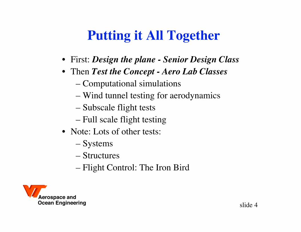
Putting it All Together
• First: Design the plane - Senior Design Class• Then Test the Concept - Aero Lab Classes
– Computational simulations– Wind tunnel testing for aerodynamics– Subscale flight tests– Full scale flight testing
• Note: Lots of other tests:– Systems– Structures– Flight Control: The Iron Bird

Aerospace andOcean Engineering slide 5
Some Connections: Mason’s Classes• Aircraft Design Class - 2 semester senior class
• Configuration Aerodynamics - a senior elective
• A Common Theme
– Why are airplanes different shapes and sizes?
Aerospace andOcean Engineering slide 6
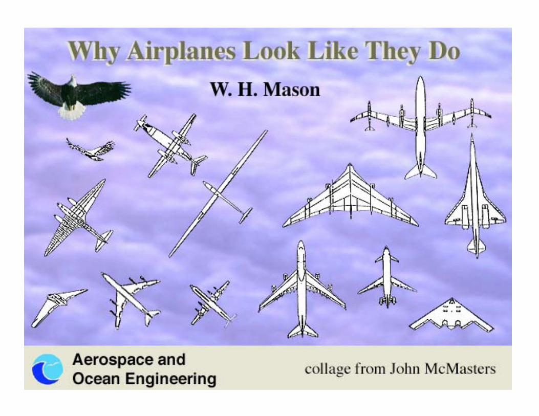
Why Airplanes Look Like They DoW. H. Mason
collage from John McMasters

Aerospace andOcean Engineering slide 7
Designer
Technologyadvances?
A new capabilitysomeone might
pay to have?
How to exploittechnology for
capability?
ConfigurationConcept
Airplane Shapes Have Changed toExploit Advances in Technology

Aerospace andOcean Engineering slide 8
Configuration Concept:• Payload
• Lifting surface arrangement
• Control surface(s) location
• Propulsion system selection
• Landing Gear
Wright Brothers:
• Innovative control concept(more important than stability)
• “Light weight” propulsion
• Continual design evolution/refinement
Amazingly Tricky to Integrate Advances in Each Technology
Aerospace andOcean Engineering slide 9
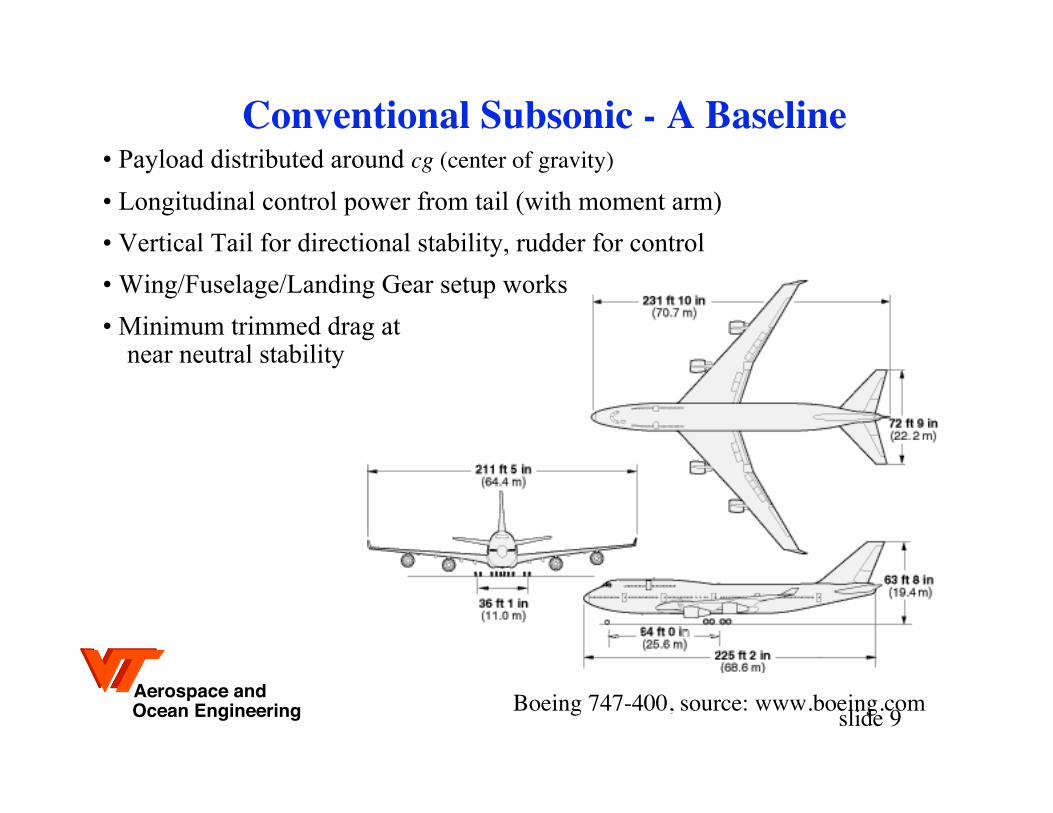
Conventional Subsonic - A Baseline
Boeing 747-400, source: www.boeing.com
• Payload distributed around cg (center of gravity)
• Longitudinal control power from tail (with moment arm)
• Vertical Tail for directional stability, rudder for control
• Wing/Fuselage/Landing Gear setup works
• Minimum trimmed drag at near neutral stability
Aerospace andOcean Engineering slide 10
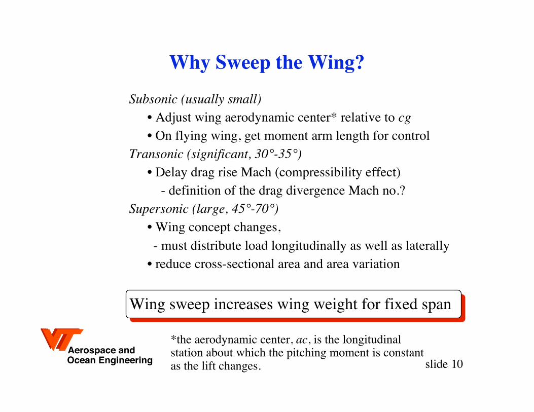
Why Sweep the Wing?
Subsonic (usually small)• Adjust wing aerodynamic center* relative to cg• On flying wing, get moment arm length for control
Transonic (significant, 30°-35°)• Delay drag rise Mach (compressibility effect)
- definition of the drag divergence Mach no.?Supersonic (large, 45°-70°)
• Wing concept changes,- must distribute load longitudinally as well as laterally
• reduce cross-sectional area and area variation
Wing sweep increases wing weight for fixed span
*the aerodynamic center, ac, is the longitudinalstation about which the pitching moment is constantas the lift changes.

Aerospace andOcean Engineering slide 11
The classic large airplane: The Boeing 747
source: www.boeing.com
Aerospace andOcean Engineering slide 12
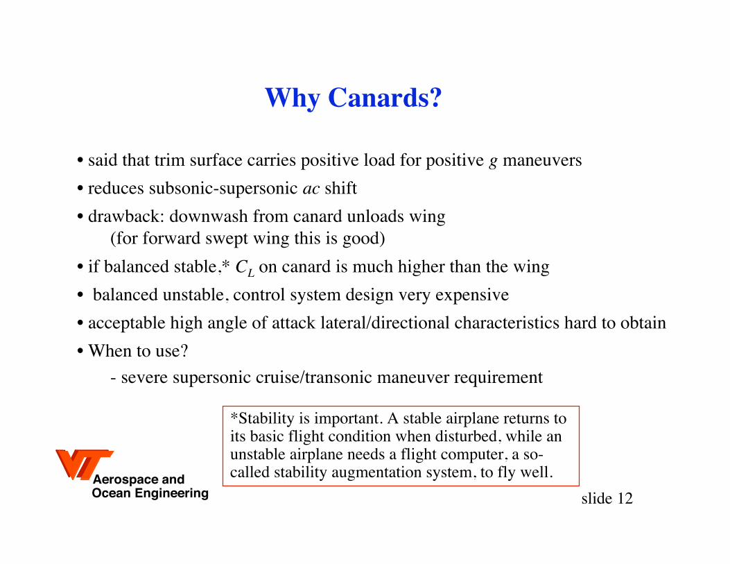
Why Canards?
• said that trim surface carries positive load for positive g maneuvers
• reduces subsonic-supersonic ac shift
• drawback: downwash from canard unloads wing(for forward swept wing this is good)
• if balanced stable,* CL on canard is much higher than the wing
• balanced unstable, control system design very expensive
• acceptable high angle of attack lateral/directional characteristics hard to obtain
• When to use?
- severe supersonic cruise/transonic maneuver requirement
*Stability is important. A stable airplane returns toits basic flight condition when disturbed, while anunstable airplane needs a flight computer, a so-called stability augmentation system, to fly well.

Aerospace andOcean Engineering slide 13
The Grumman Research Fighter
designed by Nathan Kirschbaum, Ron Hendrickson in pix

Aerospace andOcean Engineering slide 14
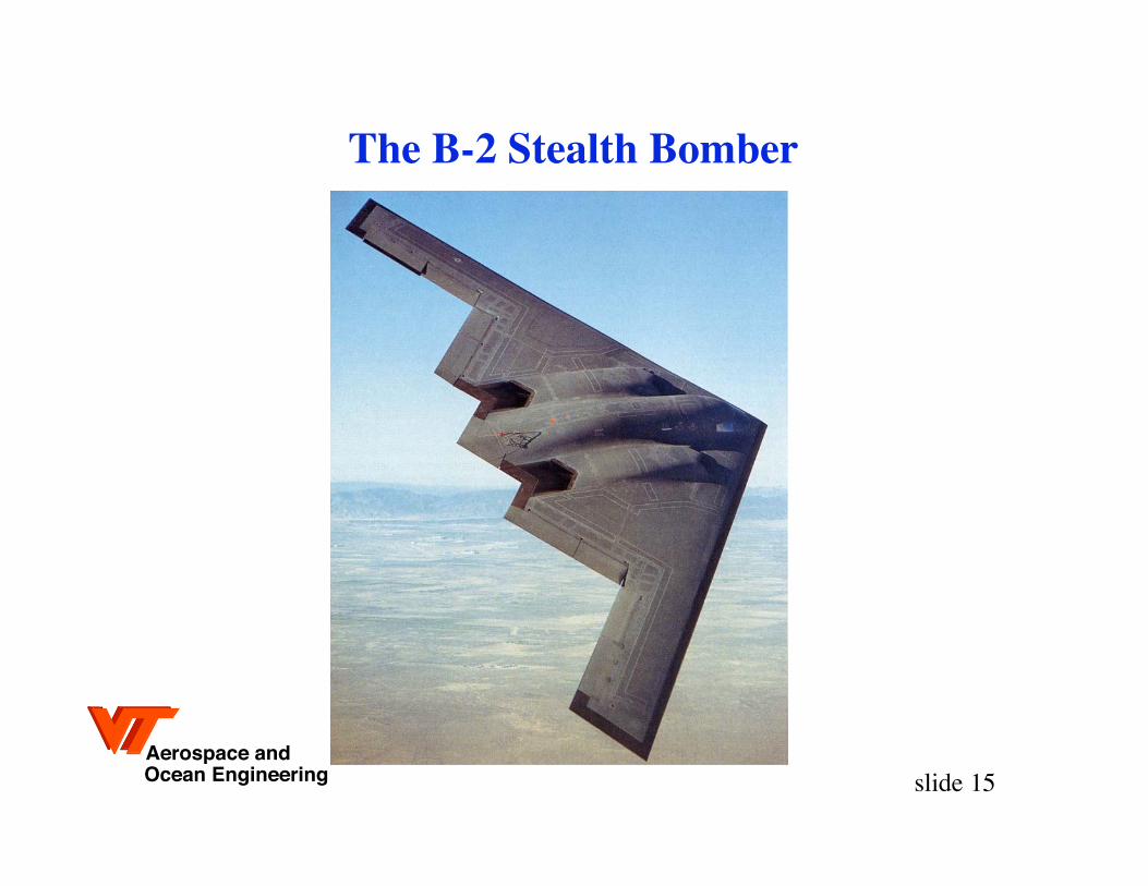
Why a Flying Wing?
• removing fuselage must improve aero efficiency
– But, payload volume distribution is still an issue
• synergistic effect with relaxed static stability
• military: stealth
• commercial: distribute load, reduce weight
Example: XB-35, YB-49, B-2
Aerospace andOcean Engineering slide 15
The B-2 Stealth Bomber

Aerospace andOcean Engineering slide 16
Computational Design Used Today
• Disciplines integrated:
– Not the optimum aerodynamic design
– Not the optimum structural design
– The Best Total System Design
• Known as MDO
– Multidisciplinary Design Optimization

Aerospace andOcean Engineering slide 17
So Will the Computer Eliminate the WT?
One complete airplane development requiresabout 2.5 million aerodynamic simulations.

Aerospace andOcean Engineering slide 18
Comptational Simulations andWT Testing are Complimentary
• Both have strengths and weaknesses
• Solving a real problem requires both
Aerospace andOcean Engineering slide 19
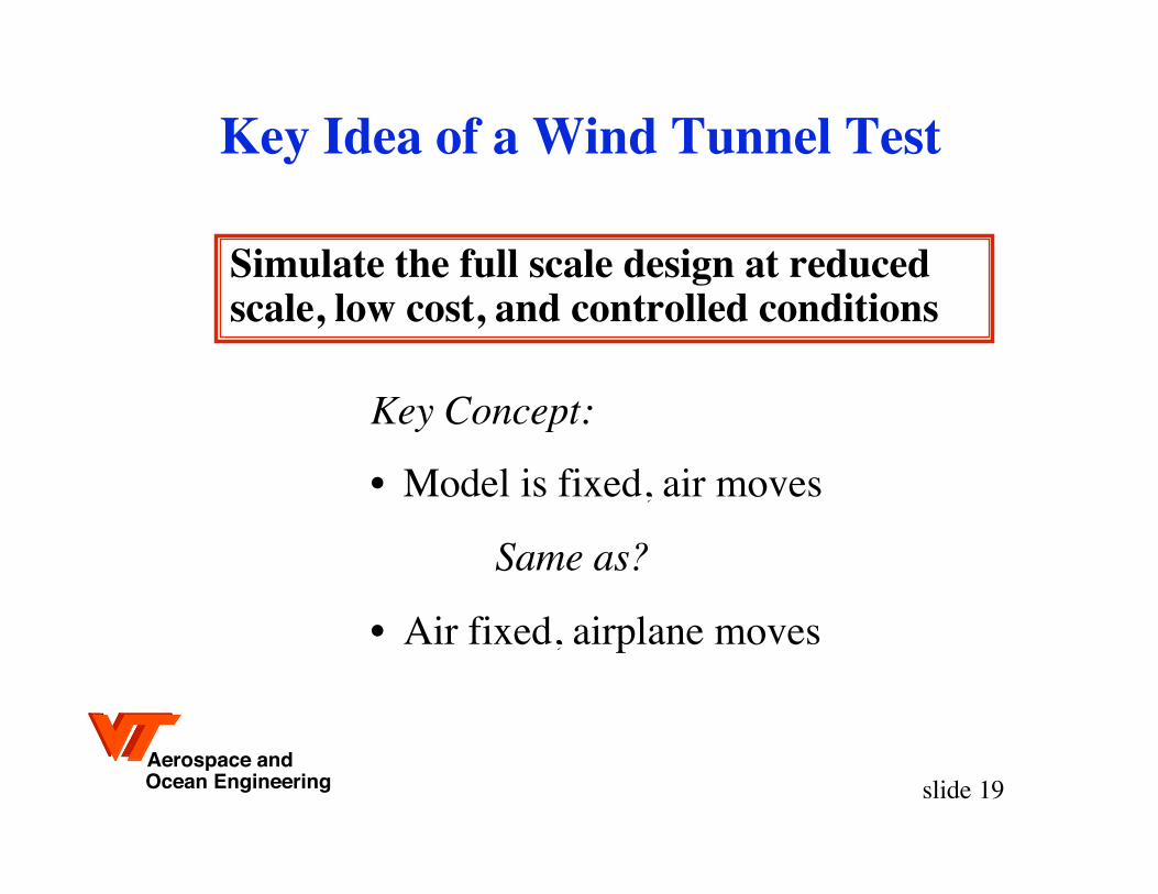
Key Idea of a Wind Tunnel Test
Key Concept:
• Model is fixed, air moves
Same as?
• Air fixed, airplane moves
Simulate the full scale design at reducedscale, low cost, and controlled conditions

Aerospace andOcean Engineering slide 20
Similarity
• Reynolds Number (Re)
– To simulate the viscous effects correctly, match theReynolds Number
– But you most likely can’t match the Reynolds number,we’ll show you why and what aeros do about the problem
• Mach Number (M)
– You are not going to get accurate aero data for supersonicflight with a subsonic test!
– To match model to full scale compressibility effects, test atthe same Mach number, sub-scale and full scale

Aerospace andOcean Engineering slide 21
Example of the Re Issue
“The Need for developing a High Reynolds Number Transonic WT”Astronautics and Aeronautics, April 1971, pp. 65-70

Aerospace andOcean Engineering slide 22
Matching the Reynold’s Number?
Re =VLµ
RefsRem
=fs
m
VfsVm
L fsLm
1µ fs
µm
: density, V: velocity, L: length, µ: viscosity,
fs: full scalem : model

Aerospace andOcean Engineering slide 23
WT vs Flight- why the NTF was built -
“The Large Second Generation of Cryogenic Tunnels”Astronautics and Aeronautics, Octoberl 1971, pp. 38-51
NTF
Aerospace andOcean Engineering slide 24
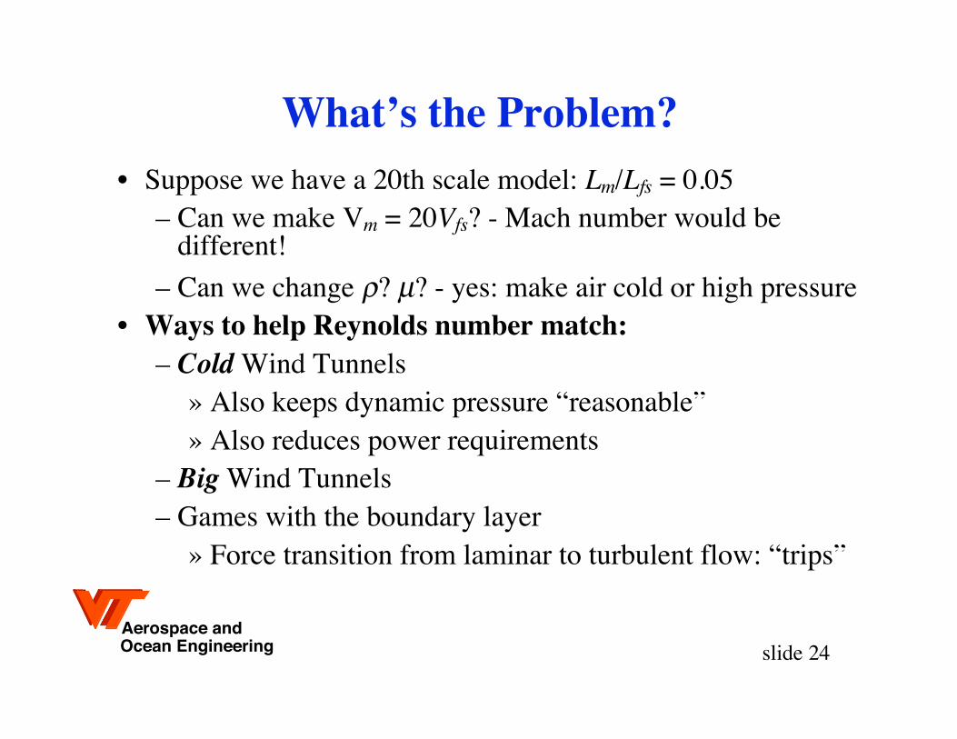
What’s the Problem?• Suppose we have a 20th scale model: Lm/Lfs = 0.05
– Can we make Vm = 20Vfs? - Mach number would bedifferent!
– Can we change ? µ? - yes: make air cold or high pressure• Ways to help Reynolds number match:
– Cold Wind Tunnels» Also keeps dynamic pressure “reasonable”» Also reduces power requirements
– Big Wind Tunnels– Games with the boundary layer
» Force transition from laminar to turbulent flow: “trips”

Aerospace andOcean Engineering slide 25
Trying to match flight Re using cryogenic nitrogen:The NTF at NASA Langley, Hampton, VA
Performance: M = 0.2 to 1.20PT = 1 to 9 atmTT = 77° to 350° Kelvin
Feb. 1982
Aerospace andOcean Engineering slide 26
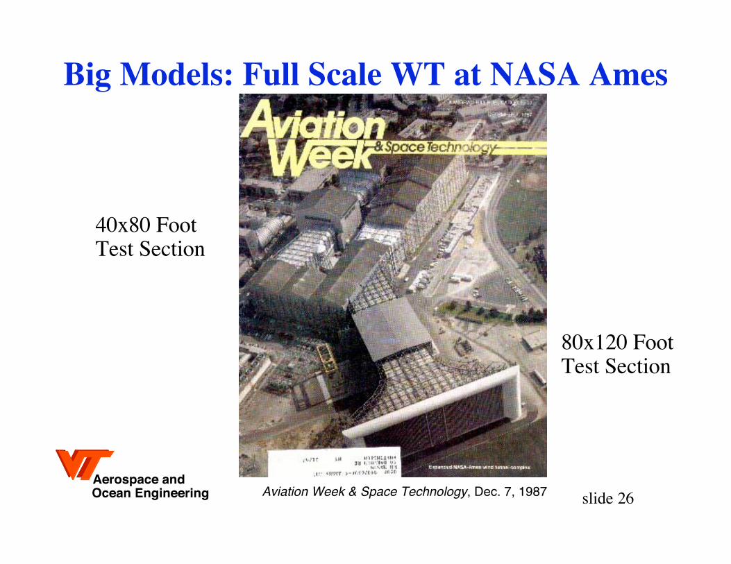
Big Models: Full Scale WT at NASA Ames
80x120 FootTest Section
40x80 FootTest Section
Aviation Week & Space Technology, Dec. 7, 1987

Aerospace andOcean Engineering slide 27
Sue Grafton with RFC at NASA Langley

Aerospace andOcean Engineering slide 28
RFC in the 30x60 at Langley: static tests

Aerospace andOcean Engineering slide 29
Free Flight Setup: A complicated activity

Aerospace andOcean Engineering slide 30
RFC Model in Free Flight at Langley

Aerospace andOcean Engineering slide 31
Flight Test
Subscale demonstration of an oblique wing airplane

Aerospace andOcean Engineering slide 32
Flight Test• The X-45A from last November
Find movies on the NASA Dryden web site:http://www.dfrc.nasa.gov/gallery/Movie/index.html
Aerospace andOcean Engineering slide 33
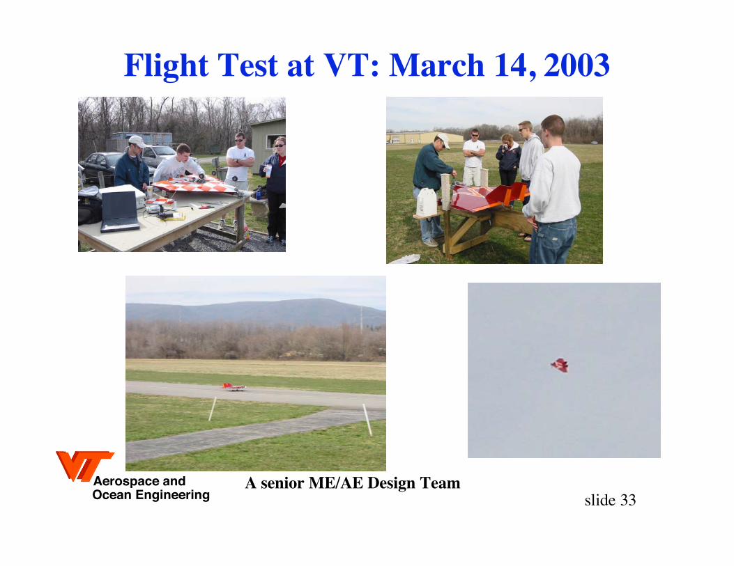
Flight Test at VT: March 14, 2003
A senior ME/AE Design Team

Aerospace andOcean Engineering slide 34
Full scale flight test the X-29

Aerospace andOcean Engineering slide 35
X-35 Flight Test Leading to the F-35!

Aerospace andOcean Engineering slide 36
Tech’s Human Powered Airplane Model
http://www.aoe.vt.edu/design/hpa/video.php
October 26,2006
Aerospace andOcean Engineering slide 37
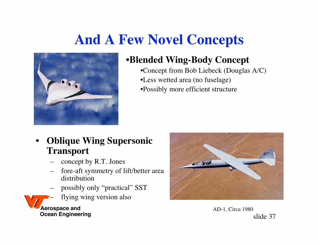
And A Few Novel Concepts
• Oblique Wing SupersonicTransport– concept by R.T. Jones– fore-aft symmetry of lift/better area
distribution– possibly only “practical” SST– flying wing version also
•Blended Wing-Body Concept•Concept from Bob Liebeck (Douglas A/C)•Less wetted area (no fuselage)•Possibly more efficient structure
AD-1, Circa 1980
Aerospace andOcean Engineering slide 38
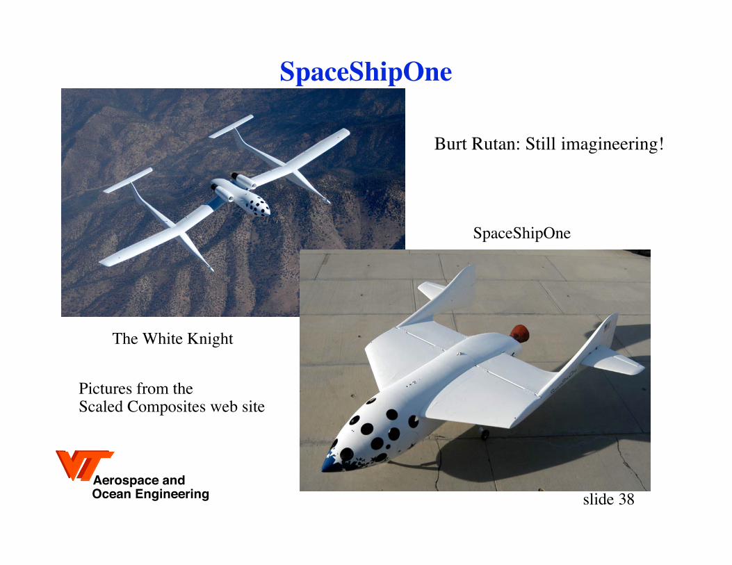
SpaceShipOne
Burt Rutan: Still imagineering!
The White Knight
SpaceShipOne
Pictures from the Scaled Composites web site
Aerospace andOcean Engineering slide 39
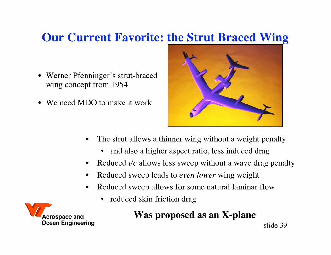
Our Current Favorite: the Strut Braced Wing
• The strut allows a thinner wing without a weight penalty
• and also a higher aspect ratio, less induced drag
• Reduced t/c allows less sweep without a wave drag penalty
• Reduced sweep leads to even lower wing weight
• Reduced sweep allows for some natural laminar flow
• reduced skin friction drag
• Werner Pfenninger’s strut-braced wing concept from 1954
• We need MDO to make it work
Was proposed as an X-plane
Aerospace andOcean Engineering slide 40
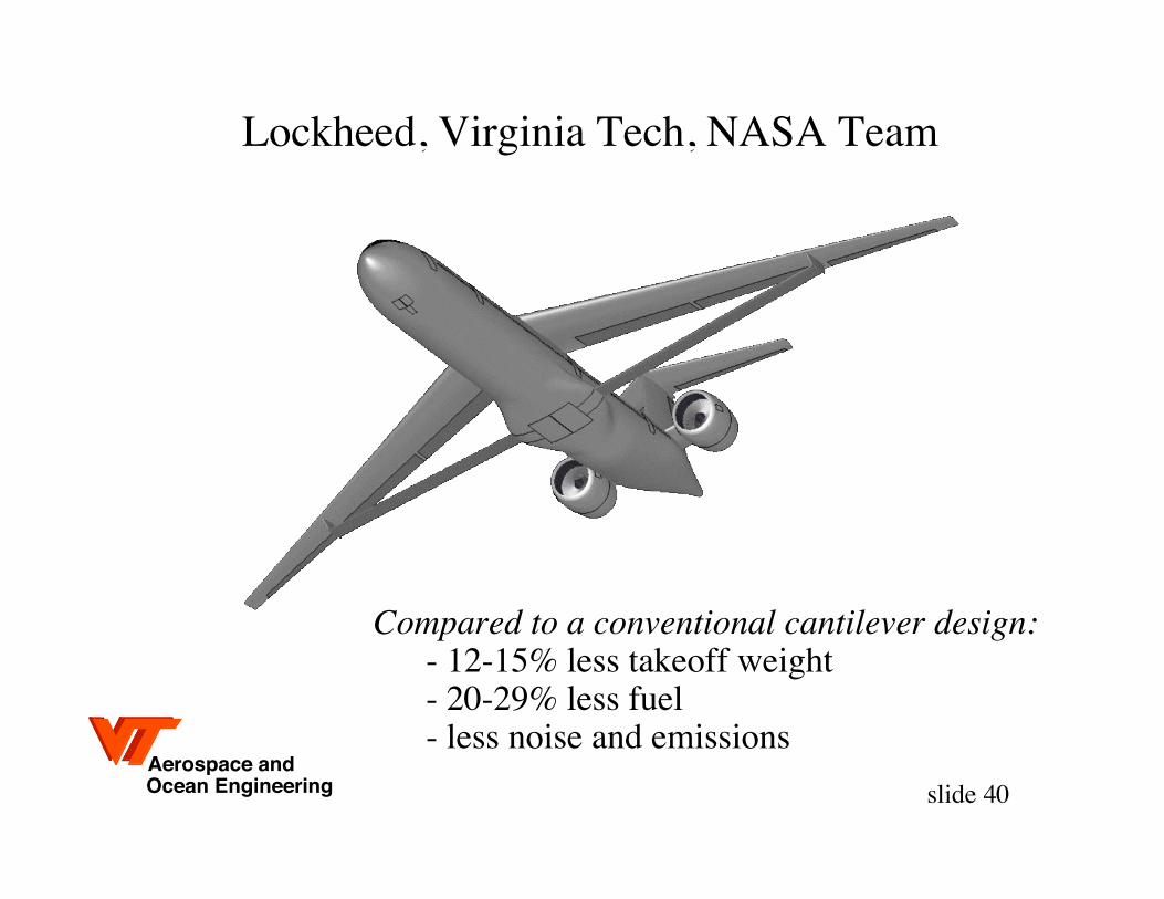
Lockheed, Virginia Tech, NASA Team
Compared to a conventional cantilever design:- 12-15% less takeoff weight- 20-29% less fuel- less noise and emissions

Aerospace andOcean Engineering slide 41
And Hope for Low-Sonic Boom Noise Flight
A modified F-5Edemonstrated a low-noiseboom on Aug. 27, 2003
So-called “boom shaping”can be used to reduce thepart of the boom that hitsthe ground.
NASA Press Release,Sept. 4, 2003
Aerospace andOcean Engineering slide 42
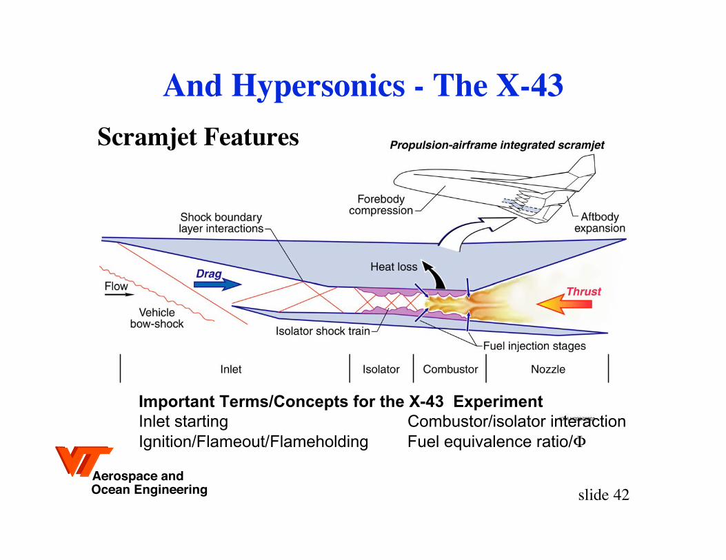
And Hypersonics - The X-43
Important Terms/Concepts for the X-43 Experiment
Inlet starting Combustor/isolator interaction
Ignition/Flameout/Flameholding Fuel equivalence ratio/
Scramjet Features

Aerospace andOcean Engineering slide 43
The Latest: UCAVsThis one is based on
Nastasi/Kirschbaum/Burhans Patent 5,542,625
Northrop Grumman Corporation, reprinted by Aviation Week, June 16, 1997
The vertical tail is eliminated for stealth, directional controlcomes from specially coordinated trailing edge deflections

Aerospace andOcean Engineering slide 44
And finally, Micro AVs!
AeroVironment, Inc.
Black Widow
• 6-inch span fixed-wing aircraft
• Live video downlink
• Portable launch/control box
• Pneumatic launcher
• 60 gram mass
• 22-minute endurance
• Estimated 10 km range
• Electric propulsion • World MAV endurance record of 22 minutes
• Smallest video camera ever flown on a UAV: 2 grams
• Smallest live video downlink ever flown on a UAV
• World’s smallest, lightest multi-function, fully
proportional radio control system: 3 grams
• First aircraft to be flown “heads-down” indoors
Achievements
Joel Grasmeyer, MS VT 1998 - team member!
Aerospace andOcean Engineering slide 45
To Conclude:There is Still Room for Dreamers
We don’t yet know what the
ultimate airplane concept is.