
AO—A080 459 ATLANTIC RESEARCH CORP ALEXA NDRIA VA KIP ...
14
AO—A080 459 A TLANTIC RESEARCH CORP ALEXA NDRIA VA KIP ~~ TIC S AND co—Etc FIG 21,9.2 * MOOCI . OF EROS! Vt BURNING OF C0! OSITE PROflLLANTS. (U) 1977 N K KING F44620—76 C—0023 (ICLASSIFIED AFOSR—TR—77—0692 Vt I I ci END DATE E IL ME 1 — 77
Transcript of AO—A080 459 ATLANTIC RESEARCH CORP ALEXA NDRIA VA KIP ...

AO—A080 459 ATLANTIC RESEARCH CORP ALEXA NDRIA VA KIP~~TICS AND co—Etc FIG 21,9.2* MOOCI. OF EROS! Vt BURNING OF C0! OSITE PROflLLANTS. (U )1977 N K KING F44620—76 C—0 023
(ICLASSIFIED AFOSR—TR—77—0692 VtI I ci
ENDDATE
E IL ME
1 — 77

1.4
/ _ •1*A MODEL OF EROSIVE BURNINC OF COMPOSITE PRO’ ELLANIS
Dr. Merrill K. KIng~~Atlantic Reset-rch Cot ,oration
AFO~R iR — 77 C~) ~
,~~ Alexandria, Virginia 22314
Abstract
Developnent of solid rocket motor designs which r fttr fore = ~~~~~~~ ~~“ (1)
aresult in high velocity flows of product gasesacross burning propellant surfaces (notably, nozzle- Values of (raft/rfore)iajtial as a function of theless rocket motors) is leading to increased occur— erosivity constant (k3) and the burning rate expon—:ence of erosive burning. In this paper , a physi- eat (n) are presented in Table I for y = .1.25. Ascally realistic picture of the effect of such cross- may be seen, for the case of no erosion (k3 = 0)-flows on composite propellant combustion , based on the af t end will recede more slowly than the forethe bending of columnar diffusion flames by the end, due to lower pressure at the aft end. As k3crossflow , is presented. This bend ing results its increases, the raf~/rfore ratio also increases,shifting of the diffusion flame heat release zone going through unity (generally desirable) at a value
~~1 toward the surface, with consequent increased heat of k3 which depends on the burning rate exponent.
feedback flux from this flame to the surface and The results of Table I give some indication of thethus increased burning rate. A relatively simple sensitivity of nozzleless motor design to the ero-analytical model based on this picture is developed sive burning characteristics of the propellant andfor prediction of propellant burning rate as a func— thus point out the importance ‘f information regard-tion of pressure and crossflow velocity, given only ing the propellant ’s erosive burning characteris-zero-cross flow burning rate versus pressure data, tics to the designer.Model predictions and experimental results are com-pared, with reasonably good agreement being found.
Table 1. Ballistic Ajsalysis of a N ozzicless Motor with Uniform Port Area.Introduction
1 + k~ M. r0 = bp°Requirements for ever higher propellant loading
fractions in solid propellant rocket motors and for fl k~ rAFT,rFOREhigher thrust-to-weight ratios have led to develop- ~~~ 0.72meat of centrally perforated grain configurationswith relatively low port-to—throat area ratios. 0.5 1.08This, in turn, results in high velocities of propel- 1.0 .~~
1.45lant gases across burning propellant surfaces in the 1.5 1:803 aft portions of these grains, leading to erosiveburning. Moreover, a series of studies has demon- 0.6 0 0.61strated that the nozzlel~ss rocket concert offers 0.5 0.92
~~~~~~~~~
eigctificant economic advantages over a more conven- 1.0 1.23tional rocket system when considered for some tacti-
1.54cal weapon systems. This concept requires that the 1.5flow within the bore or central perforation of a 0.8 0 0.52grain aécelerate to the point that sonic conditions 0.5 0.78are achieved at the aft end. In this situation,the high velocity environment.leads to a realm of 1.0 1 05erosive burning not previously considered. The .. 1.5 13 1eff:-~~s are critical in that the erosive burn rate
• contributions strongly influence performance level, -
performance repeatability and thrust misalignment. Development of a better understanding of theMore than in any conventional motor , the exact era- effects of crossflows on solid propellant combustionsive burn rate behavior must be held constant from is needed for accomplishment of accurate motor per-batch to batch if reproducibility is not to be a forsnance predictions in terms of both mean iatericr
• problem. The performance sensitivity of a nozzle— ballistics analysis and prediction of motor stabilityless motor to erosion is due to the fact that the characteristics. With such understanding, the motormaximum erosion occurs at the choke point in the designer can either dasign his grains to compensatebase. Since this point is the effective throat area, for mean erosive burning effects on grain burn pat-and the throat area versus time is thus a function tern, or, knowing how propellant formulation para-of regression rate, the result is a chamber pressure meters affect erosion sensitivity, vary propellanthistory which varies strongly with erosion, parameters in such a way as to optimize these e f f e c t s .
A review of the literature indicates that there isIn a nozzleless motor , two parameters which no unifying predictive model for erosive burning of
affect burning rate , prcasure and crossflow velocity, solid prop~llants,~~~ vary strongly from the fore end to the aft end of
the grain, static pressure decreasing and crossflow General observa~iQns of importance from past cx-velocity increasing with distance f rom the head end perimencal studies 1include:
C)of the grain. Assuming that an erosive burning rate
1. Plots of burning rate versus gas velocity orexpression of the form , rfr0 1 + kj~l~ is appli—cable (with r0 •~ bp~), it may be shovn~ that for mass flux at Constant pressure are usuallyconstant port arcs along the grain: not fitted best by a straight line._____________________ 2. Threshold veloci les and ‘negative” erosion
• *mim effort was supported by AFOSR under Contract rates are often observcd.
~j .•, No, F44620-76-C-0023, monitored by Maj. Thomas Meter 3. Slower burning propel larsta are more strongly**Chlcf Scientist , R.’search & Technology, Mambor AIAA - -
C-,I Approved for pub lic ~e1oa~~~;diStribution un1t~ajt o~ .
~~~~~~~~~~ ~~~~~~~~~~~~~~~~ ~~~~~~~~~~~~~~~ ~~~~~~~~~~~~~~~~~~~~~~~~~~~~~~~~~~~~~~~~~~~~~~~~~~~~~~~~~~~~~~~~~~~~~~~ ~~~~~~~~~~

r ~~~~
—
T~~~~’~~~
I
4I,
~ O~ ~~~~~~~~
~~~~ .1 re,0rt
~~~~~ lAW A~~T~11
•i. 0fltcer
~~~~~~~~~~~~~~~~~~~~ ~~~~~~~~~~~~~~~~~~~~~~~~~~~~~~~~~~~~~~~~~~~~~~~~~~ — - ~~~~~~~~~~~~~~~~~~~~~~~~~~~~~~~~~~~~~~~~~~~~~~~ ~~~

— -
~~~~~~~~~ 7 S ~~TI~~I —
~~~~
-
T I s ~~~~~~~~~~~~~~~I ~ p. Pog. ow er o l ) — ~~
~~~~~~affected by crossflows than higher burning- tncrease in total rate at a given pressure , very un-rate formulations, likely within the constraints of other assumptions
4. At high pressure, the burning rate under in the model. This problem has been discussed inerosive conditions tends to approach the detail by King28, with derivation of a modifiedsame value for all propellants (at the same Lenoir and Robillard expression allowing for theflow velocity) regardless of the burning coupling of [lame standoff distance with ~urnir.~;rate of the propellants at zero crossflow. rate. While Lenoir and Robillard assume r r9 + re,
5. Erosive burning rates do not depend upo n gas allowance for this coupling resul ts in r (r02/r)temperature of the crossflow (determined from re. In physical terms , Lenoir and Robillard havetests in which various ‘driver propellants” failed to account for the fact that increased burn-products are flowed across a given test pro— ing rate, caused by erosive feedback at constantpellant). pressure , results in the propellant flame being
pushed further from the surface, decreasing its heatThere is, however, very little data available feedback rate , and thus decreasing the propellant
for high crossflow velocities (greater than H 0.3). burning .rate part of the way back toward the baseIn addi t ion, there has been no study in which var— rate.ious propellant parameters have been systematicallyvaried one at a t ime. Such a study is necessary Table IL General Types of Models of Erosive Burnrng Developed to Date.for determination of erosive burning mechanisms andproper modeling of the erosive burning phenomena. I. MODELSBASED O.4 HEAT TRANSFER FROMA CORE GAS INMuch of the past work has not resulted in instant— THE PRESENCE OFCROSSFLOWaneous (as opposed to averaged over a range of pres- L ENOIR&ROBI LL A RD 112)sure and crossflow velocity) measurements of eros- BURI~ K ANDOSBORN (13)ive burning rates under ;,oll characterized local ZUCROW OSBORN AND MURPHY 1141f low conditions. SADERHOLM (3)
MARICLUND Ii)jo~u c& BLAGOJEvIc (151
From the above disct:-~ ‘ ion, it is apparent that2. MODELS BASED ON AL T ERATION OF TRA NSPORT PROPERT IESdevelopmen t of an anal.t ~cal model of erosive burn- IN REGION FROM SURFACE TO FLAME ZONF BY CHQS$FLO(, .
ing , properly des cribi ng the physical ef fects which GENERALL YD UE TOTURBULENCE EFF ECTS INCL (.h)ESresult in augmentation of solid composite propel- ~~~~~~~~~~~~~~~~~~~~~~~~~~~~~~~~~~~~~~~~~~~~~~
-lan t burning rate by crossf lows , coupled with an FUELPOcK ETSLEAV INGSURFACE.exper imental effort to systematically define the SADERHOLM. BIDDLE. CAVE NY . ., at 16)effects of various formulation parameters on eros— LENGELL~ (17)lye burning at crossflow velocities up to Mach 1 is CORNER (DOUBLE BASE (18)of great Importance to the design and development VANDEPIKERCKHOVE DOUBLE-BASE) (19)of advanced solid rocket systems. ZELDOV ICH (D OUB LE• B A SE~~(2O )
GECKLER (211Background : Existing Models
1 MODELS BASED ON CHEMICALLY REACTING BOUNDARYLAYER THEORY (HOMOGENEOUS SYSTEMS ONLYI
The objectives of a theoretical model of erosive TsuJu nburning are to provide a means of predicting thesensitivity of propella nt combustion rate to gas ICuO.et aI (24)flow parallel to the ablating surface and to m di- 4. OTHERcate what effect various formulation parameters KLIMOV (25 )have on this sensitivity. An acceptable model must MOLNAR (26)account for: (1) any effects observed when cross- MILLER (271flow gas temperature is varieçl ; (2) observed pres— RINGsure dependency; and (3) nullification of catalystactivity under erosive conditions. This model A more general weakness of model : in the firstshould provide an explanation of the observed be- category is that these models predict substantialhavior in terms of the hydrodynamic conditions in- dependence on the temperature of the core gas: suchduced by a crossflow coupled with the chemical and dependence was found by Mark iund and Lake8 te bephysical processes that constitute the propellant completely absent. Analysis of the Lenoir anddeflagration mechanism. Robillard treatment indicates that the erosive con-
tribution to burning rate (re) is given by:Over the years, a large number of erosive burn-
~ 8 0 2ing models , of varying degrees of sophistication, G •
~ ~s (Tcore as
T ) . (2)have been developed - a list of models examined by
g gthis author is presented as Table II. These models for a given test propellant and geometry. Rut , atgenerally fall into one of three categories, as in- fixed crossflow velocity and pressure , C is inverslvdicated. The first category is based on the asstnnp- proportional to the core gas (driver propellant pro-tion that the erosive burning is driven by increased duc ts) temperature while Ugas is roughly direc t lyheat transfer from the mainstream gas flow associat- proportional to this temperature. Therefore,ed with increased heat transfer coefficient with T~
0’6 ‘ T (3)increased mass flux parallel to :he grain surface. re core gas \Tcore ,gas
_ a
The best-known and most widely used erosive burning However, Markiund and Lake performed a set of exper-
• slodel, that of Lenoir and Robillard 12, falls into iments in which crossflow velocity and pressure werethis category. In this model, the authors calculate held constant while the driver propellant was chant-the total burning rate (r) as the sum of the normal ed from a 1700°K propellant to a 2500~ K propel lan t ,(no crossflow) burning rate and a second erosive with T5 being approximately 800°K in both cases.term resulting from heat transfer from the “core” Thus, the Lenoir and Robillard theory would m di-f low to the propellant surface. This equation en- cate that:tails an a priori assumption that the pressure-de-
— pendent “base” ra te (r0) is unaffected by an- - -
4- — 2
I
~~~. ~~~~~~~~~~~~~~~~~~~~~~~~~~~~~~~~~~~~~~~~~~~~~~~~~~~~~~~~~~ ~~~~~~~~~~~~~~~~~~~~~~~~~~~~~~~~~~~~ ~~~~~~~ ,
- •~~~~ ~~~~

—~~~~~~ -~~~~~
¶ F.. 6~~~ t I ~h..$ 1 I . r s) .,, ,~ I— • 5 I • - , -
version of the second-order closure method ofT~~~, 2500’K driver - -. .. Donaldson is used to calculate the details of ther
-- 900 \1700 J
- 1.50 L41 turbulent flow field. To date , this flow fielde, 1700 K driver analyuis has been coupled only with a very simpleThat is , with the higher driver gas temperature model of propellant combustion in which the propel-case, the erosive burning rate component of the tot- lant surface temperature is assumed to ic indcç nd-al burning rate should be 50 percent higher than ent of burning rate , the mass burning rate is assum - • -
that for the low driver gas temperature. However, ed to be directly proportional to the heat fluxas mentioned , Marklund and Lake observed no differ- from the gas to the surface , and the gas phase re-ence in erosive rates in the two cases. This ob action is assumed to be described by a single stepserved lack of dependence of the erosive burning homogeneous reaction which is first order with rc-rate on core gas tempera ture tends to cast doubt on spect to fuel concentration and first order withall models in the first category of Table II, respect to oxidizer concentration. Under these
conditions , the model predicts a threshold velo-The second category of models listed in Table II city for erosion followed by a quasi-linear depend-
includes models based upon the alteration of trans- once of burning rate on crosaflow velocity due toport properties in the region between the gas flame turbulence entering the propellant flame zone.and the propellant surface by the crossflow , gener-ally due to turbulence effects. Included in thiscategory are models in which the thermal conducti- Kt~o and Razdan
24are also using a second-ordervity in this region is raised by turbulence and turbulence closure model for characterization of themodels in which the time for consumption of fuel gas flow field in erosive burning situations , the do-pockets leaving the surface is reduced by the e f f ~~ts sure model being used differing from that beingof turbulence on diffusivity. Four of these models used by Beddini. In add ition , postulated flamewere developed for double-base propellants as m di- mechanisms (the details of which are unknown to thiscated , and will not be reviewed here. Of the con- author) for composite propellants are being coup ledposite propellant models in this category , that of into the analysis. At this time, the governingLengelle17 appears to be the most advanced. The equations have been developed and boundary condi-baaic propellant combustion mechanism assumed is the tions defined , but the equation solving proceduregranular diffusion model in which pockets of fuel has not been completed.-vapor leave the surface and burn away in an oxidizer
2continuum at a rate strongly dependent upon the rate The Klimov model 5is mainly aimed at calculationof micromixing of the oxidizer vapor into the fuel of threshold crossflow velocities (below which thevapor pocket. The driving mechanism by which the propellant is unaffected by crossflow). Klimovcrossflow is assumed to increase the burning rate claims that the threshold velocity is the mainis through increased turbulence associated with in- stream crossflow velocity above which the “turbu-creasing crossflow raising the turbulent diffusivity lance front” subsides onto the propellant surface ,in the mixing region (thus increasing the rate of and presents boundary layer analysis procedures formixing of the binder and oxidizer product gases) and calculating this threshold velocity as a functionraising the effective turbulent thermal conductivity, of the transpiration (blowing) velocity of the gasesThe increase in thermal conductivity increases the ablating from the propellant surface. In addition ,heat transfer rate from the flame to the surface, he postulates that negative erosion (sometimes seenwhile the increase in mixing rate just offsets the at low crossflow velocities) is due to the “sitrrinz
• increase in gas velocity away from the surface, with up” of cool streams of binder decomposi tion produc tsthe result that the flame offset distance remains over the oxidizer surface , leading to intensificat-constant. There are several weaknesses associated ion of their cooling effect and to screening of heatwith the Lengelle model: (l).the granular diffusion feedback from the diffusion flame.flame model is not physical ly realistic ; (2) theaninonium perchlorate monopropellant flame is ignored ; Molnar ’s model26 , developed for homogeneous pro-and (3) the boundary layer treatment used to calcu- pellants with a laminar crossflow , is based on anlate the dependence of the effective turbulent dif- assumption (which does not appear to this author tofusivity and conductivity ott the crossflow is un- be substantiated) that the lateral velocity gradientrealistic in its use of a 1/7th power velocity law at the burning surface governs erosive burning.all the way from the free—stream to the surface. Miller27 assumes that the time for a unit of propel-
lant to be consumed is a linear sum of a chemicalOf the three models listed in the third category reaction time and “the time required for turbulent
(models based on chemically reacting boundary layer transport of heat to the propellant surface” - suchtheory) one is complete, while the remaining two are an additivity approach does not appear to thisin development. The comp leted model , by TsuJi22 , author to be physically realistic.is unfortunately not particularly useful due to theassumption of a totally lam inar boundary layer and Of the models briefly discussed above , those of
• limitation to a situation where the free-stream vel- Lengelle’7, Beddini , et al 23 , and Kuo and Razdan2~ocity is proportional to the distance from the head- appear to be the most advanced (although it is notend of the grain. Other simplifications include clear at this time how the latter two teams will
• assumption of premixed stoichk’:etric fuel and oxi- build the complex heterogeneous flame structurediter (rendering the model inapplicable to composite associated with composite prope l lant combustion into
• propellant systems) and use of one-step global kin- their fluid dynamic boundary layer treatments).etics. Coimnon to all three of these models is the assump-
2 tion tha t the increase in propel lant burning ra te
In the model of Beddini , et al ~~, primary empha- associated with crossflow results from turbulenceii. is placed on analysis of a well-developed tur- associated with this crossflow penetrating be tweenbulent flow field in a propellant grain port for the propellant gas flame zone(s) and the surface ,definition of turbulent transport of heat, mass , causing increases in mass and energy transport rates,and momentum in the boundary layer. An extended However, for a typical propellant containing oxidizer
3
I
~-‘ - - ~~~~~~~~~-_(~~~~~ 2 ~~~~~~~~~~~~~ — ~~- ~~~~~~~~~~~~~~~~~~~~~~~~~~~~~~~~~~~~~~~~~~~~~~~~~~~~~~~~~ — - ~~ ~~•~‘
r ~~~~~~
-
- ~~~~~~~~~~~~~~~~~~ • T • • • -
-- •1-particles with diameters of from lO~~o5O um dif face in exactly the Sante way, the variation will notfusion flame offset distances may be calculated to be great. Thus fuel and oxidizer gas columns leav- 2
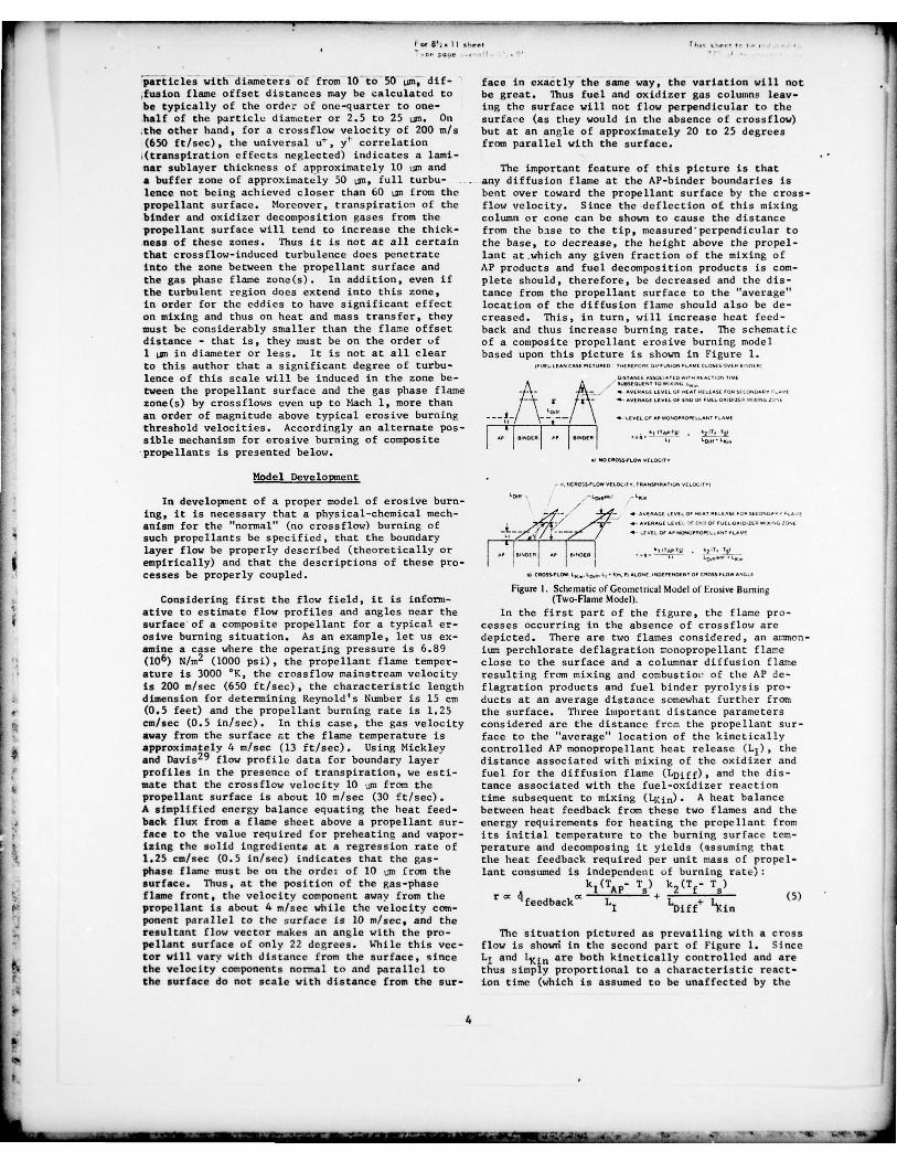
be typically of the order of one-quarter to one- ing the surface will not flow perpendicular to thehalf of the particle diameter or 2.5 to 25 usa. On surface (as they would in the absence of croasfiow)the other hand , for a crossflow velocity of 200 n/s but at an angle of approximately 20 to 25 degrees(650 ft/sec), the universal u+, yt correlation from parallel with the surface.(transpiration effects neglected) indicates a lami-nar sublayer thickness of approximately 10 tim and The important feature of this picture is thata buffer zone of approximately 50 sn, full turbu- - any diffusion flame at the AP-binder boundaries islence not being achieved closer than 60 ian from the bent over toward the propellant surface by the cross-propellant surface. Moreover , transpiration of the flow velocity. Since the deflection of this mixingbinder and oxidizer decomposition gases from the column or cone can be shown to cause the distancepropellant surface will tend to increase the thick- from the base to the tip, measured perpendicular toness of these zones. Thus it is not at all certain the base, to decrease, the height above the propel-that crossflow-induced turbulence does penetrate lant at which any given fraction of the mixing ofinto the zone between the propellant surface and AP products and fuel decomposition products is corn-the gas phase flame zone(s). In addition , even if plete should , therefore , be decreased and the dis- 2the turbulent region does extend into this zone , tance from the propellant surface to the “average”in order for the eddies to have significant effect location of the diffusion flame should also be de-on mixing and thus on hea t and mass transfer, they creased. This, in turn , will increase heat feed-must be considerably smaller than the flame offset back and thus increase burning rate. The schematicdistance — that is, they must be on the order of of a composite propellant erosive burning model1 LB~ in diameter or less. It is not at all clear based upon this picture is shown in Figure 1.to this author that a significant degree of turbu—
• lence of this scale will be induced in the zone be— Atween the propellant surface and the gas phase flame .
~~\_
zone(s) by crossflows even up to Mach 1, more than ~an order of magnitude above typical erosive burning
~~~ \_ ..°
~~._ .•
threshold velocities. Accordingly an alternate pos— -sible mechanism for erosive burning of composite ~ ~~~~~~ ~ ~~~~~~ ~ -•
propellants is presented below..2 NO C~ OSS.FLOW VI LOCtt Y
Model Development— UCR OtS-FL OW VRL OCI T Y . rRA r ,SpInro, v L 2 O c y2 ~
In development of a proper model of erosive burn- ~
°“ /~~~
“ ing, it is necessary that a physical-chemical mech— -~ • ~~~~~~~~~~~~~~~~~~~~~~ ro coS ...~anism for the ‘normal (no crossflow) burning of
~ , 1. -
~~ ,such propellants be specified , that the boundary ~ • -
layer flow be properly described (theoretically or ,~,,,
~. ~~~~ , ‘~~.V s
empirically) and that the descriptions of these pro- Icesses be properly coupled. ., C•oR Ow~~~~,. .~~,,. L, • . r~~~~osr
Figure 1. Schematic of Geometr Ical Model of troupe Bumin~Considering first the flow field, it is inform. (Two-Flame Model).ative to estimate flow profiles and angles near the In the first part of the figure, the flame pro-
4 surface of a composite propellant for a typical or- cesses occurring in the absence of crossflow areos ive burning situation. As an example , let us ex- depicted. There are two flames considered , an atrmon-amine a case where the operating pressure is 6.89 ium perchiorate deflagration monopropellant flame
• (106) N/rn2 (1000 psi), the propellant flame temper— close to the surface and a columnar diffusion flameature is 3000 ‘K, the crossflow mainstream velocity resulting from mixing and combustioi- of the AP de-is 200 n/sec (650 ft/sec), the characteristic length flagration products and fuel binder pyrolysis pro-
• dimension for determining Reynold’s Number is 15 cm ducts at an average distance somewhat further front• (0.5 feet) and the propellant burning rate is 1.25 the surface. Three important distance parameters
• cm/sec (0.5 in/sec). In this case, the gas velocity considered are the distance from the propellant sur-away from the surface t t the flame temperature is face to the “average” location of the kineticallyapproximately 4 n/sec (13 f t /see) . Using Mickley controlled AP monopropellant heat release (L1), theand Davis29 flow profile data for boundary layer distance associated with mixing of the oxidizer andprofiles in the presence of transpiration, we est i— fuel for the diffusion flame (LDiff) , and the dis-
4 mate that the crossf low velocity 10 Um from the tance associated with the fuel-oxidizer reactionpropellant surface is about 10 m/sec (30 f t /sac) , time subsequent to mixing (
~~<j n)’ A heat balanceA simplified energy balance equating the heat feed- between heat feedback from these two flames and theback flux from a flame sheet above a propellant sur- energy requirements for heating the propellant fromface to the value required for preheating and vapor- its initial temperature to the burning surface tent-izing the solid ingredients at a regression rate of perature and decomposing it yields (assuming that1.25 cm/sec (0.5 in/see) indicates that the gas- the heat feedback required per unit mass of propel-phase flame must be on the ordet of 10 usa from the lant consumed is independent of burning rate):surface. Thus, at the position of the gas-phase k
I(TAP
_ T) k2
(Tf_ T)
flame front, the velocity component away from the rm 4feedback nt L + T + T (~)propellant is about 4 n/sec while the velocity corn- I Diff ‘l(inponent parallel to the surface is 10 rn/see, and the
• resultant flow vector makes an angle with the pro- The situation pictured as prevailing with a crosspellant surface of only 22 degrees. While this vec- flow is showti in the second part of Figure 1. SincetoT will vary with distance from the surface , since L1 and ~~~ are both kinetically controlled and arethe velocity components normal to and parallel to thus simply proportional to a characteristic react-the surface do not scale with distance from the sur- ion time (which is assumed to be unaffected by the
4I
I,.
-~~~~~ . -
~~~~~~~~~~~~~~~~~~~~~~~~~~~~~~~~~~~~~~~~~~~~~~~~~~~~~~~~~~~~~~~~~~~~~~~

r w ‘~~~
- -~~~~~~~~~~~~~
- --~~~~---
~~~-
-~~~~~~~~~~~ ~~~~~~~~ ~~~~~~1.• 1 . 1 2 . • . .~ . • 2 ~ 1 . 2 - • -
crossflow) multiplied by the propellant gas velocitymonnal to the surface (which for a given formulation
r - A3? [i
+ A4
1/2
is fixed by burning rate and pressure alone) these —
~ + A d2 P2distances are fixed for a given formulation at a 5 pgiven burning rate and pressure , independent of the for burning in the absence of crossilow. Across flow velocity. Of course , since cross flow vel- regression analysis using no-crossflow burn-ocity affects burning rate at a given pressure thro- ing rate data is performed to obtain best fitugh its influence on the diffusion process as di,- values for A3, A4, and A5. (d~ is the aver-cussed below, L1 and 1lUn are influenced through the age asisnootsan perchlorate particle size. Forchange in burning rate , but this is simply coup led a given propellant, the burning rate datainto a model by expressing L1 and l
~~j 1~ as exp licit may be just as effectively regressed on A3,
functions of burning rate and pressure in that model. ~~~ , and A5d~~, eliminating the necessity ofThe important point is that they can be expressed actually detining an effective average parti-
as functions of these two parameters alone for a cle size.)given propellant. However, the distance of the mix-ing zone from the propellant surface is directly 3. From these results , ex pressions are obtainedaffected by the crossflow. It may be shown through for L1, L.,~iff , and 1i in as functions of burn-geometrical arguments coupled with the columnar di f— ing rate (Pr iTt) and press ure .fusion flame height analysis presented by Schul tz , 4. These expressions arc combined with an analy-Penner and ~reen~~
), that LD i f f measured along a u s of the boundary layer flow (which givesvector coincident with the resultant crossflow and the crossflow velocity as a function of dis-transpiration velocities should be approximately the tance from the propellan t sur face , mains treamsame as LDiff in the absence of a crossflow at the veloci ty , and propellant burning rate) tosame burning rate and pressure (except at very high permit calculation of the angle 0 (Figure 1),ratios of local crossflow velocity to transpiration L1, LDiff, 11in’ and il for a given pressurevelocity) . That is, the magnitude of LDj ff is essen- and crossflow velocity.tiall y independent of the crossflow velocity, altho-ugh its orientation is not. Thus, the distance from In the derivation of a burning rate expressionthe surface to the “average” mixed region is deere- for a composite propellant in the absence of a cross-ased to LDiff sin 0 where 0 represents the ang le flow, an energy balance at the propellant surfacebetwee.~ the surface and the average flow vector in is first written as: (See Figure 1.)the mixing region. The heat balance at the propel-lant surface now yields: XA~
Tf_Ts) -
~~(T - T_____________ AP a
~Ec (T -T )k1(T — T ) k (T — T
~ (6) Diff U~ in)
‘~ L
1 -
p s o (8)AP s 2 f am m ~~~~~~~~~ L1
+ L~~.f f sin ~~~~~ +
~VAP ‘~ x1
This picture has been used as the basis of devel- The first term of this equation represen ts heat fluxoptnent of a model for prediction of burning-rate from the final fI~~ne to the surface , the second re-versus pressure curves at various crossflow velo- presents heat fliza from the A? monopropellant flame ,citie~s, given only a curve of burning rate versus and the third represents the heat flux requirementspressure in the absence of crossflow. This model for ablation of the propellant at the mass flux, 1.employs no empirical constants other than those Several simplifying assumptions are obviously invol-obtained from regression analysis of the no-cross- ved in writing of the equation in this form. Pro-flow burning rate data. Thus , although it is not bably the most important and tenuous of these isas powerful as a model which would permit prediction the assumption that Qpj~ is independent of burningof erosive burning phenomena with no burning rate rate (or it) and of pressure. In the Zeldovich pie-data at all , but only propellant composition and ture of solid propellant combustion , where subsur-ingredient size data, it is still a very useful tool face exothermic reactions with fairly high activa-in that it permits prediction of erosive burning tion energies are considered to dominate , this wouldcharacteristics given only relatively easily obtain— be a very poor assumption, but in the generallyed strand-bomb burning rate data. (By comparison, accepted picture of solid propellant combustion in
Ithe Lenoir and Robillard model employs two free con- this country , it as not a bad approximation. Instants which are adjusted to provide a best fit of addition, it is assumed that the surface temperatureerosive burning data for a given propellant and is nearly constant with respect to pressure and burn-since since these constants vary from propellant to ing rate , with the resultant uncoup ling of this heatpropellant , the Lenoir and Robillard model does not balance equation from a surface regression ratepermit ~ priori erosive burning predictions for new Arrenhius expression. Finally, it is assumed tha t
4 propellants without some erosive burning data, where for the diffusion flame , a distance associated withas the model presented here does not require such mixing may be added linearly to a distance associat-data.) ed with reaction delay to yield a total flame offset
distance, a fairly gross simplification.• The general approach followed in development of
this model is: The monopropellant AP flame offset distance , L1,may be expresse,. as -the product of a characteristic1. The expressions for L1, LDiff, and 1%in ~~ reac tion time , i 1, and the linear velocity of gasesfunctions of burning rate (or burning massleaving the propellant surface:flux , iTt), pressure, and propellant properties
are derived and substituted into a propellantIIsurface heat balance, L = — (9)I I D
2. The resulting equation is worked into the gas
form (developed in succeeding paragraphs): For a second—order gas-phase reaction (generally1¼ assumed), r~ is inversely proportional to pressure ,
and for a given formulation, the gas density is
5
- • — ~~~~~~~~~~~~~~~~~~~~~~~~~ ~~~~~~ - : I • ~~ • . “•~~~ ~~~ ~~~I

r~- w-_-•-
~---
~~~~~~~~~~~~~~~~~~~~~~~~~~~~~~~~~~~~~~~~~~~~~~~~~~~~~~~~~~~~~~~~~~~~~~~~~~~
--- •- •
~~~~~~~~~
- • - —
~~~~~~~~~~
—
~~
-•.•--- - •
~~
—
~
--_ -
~~
- ••
I , 5’ . II sh.,~ T ,_ • .~~.. , •- . I . - -directly proportional to pressure, yielding: ‘
~~~~~~~~~~~~~~~~ K~ r (19)K1iTt/P
2 (10) I~~ K r (20)A similar analysis for ~~~ yields:
1~un
K2iTt/P2 (11) - L
1 = K~ r (21)
For a columnar diffusion flame, it may easily be Vtranspiratj = K’ m (22)on 3shown3° that the diffusion cone height, Ti iff’ may
Y=~~iff sin ~
= K~ r sin 0 (23)be expressed as: y
LB = K ~~2 (12)
K ’ ~~~ in ~) (24)iff 3 p UCrOssflow, y_L~fffsin 9 9 y=L~~~~S
Equations 8 and 10 - 12 may be combined to yield: -
A4 1/2 VT i i
Sin 0 = —_____________________________________________________________ (25)
+r ~~~
= A3P[l 1 + A d2 2 ] (13)
~~~~ranspiration~ ~~~~~~~~~~~~~~~~~~~~5 p
Burning rate versus pressure data for a given pro- where (I - T )A d2pellant in the absence of a crossflow may then be f ~ ~ p 0~ (26)analyzed via a fairly complicated regression analy-
K~ =
u s procedure to yield values of the constants A3, A2A3~ A4
A4, and A5 (or A5d2) for that given propellant.The constants K1, ~2, and K3 are related to these K~ = p
8 (T~ — T)/A2 (27)
constants in turn by: ~ T pf s(TAP - T ) A
8 K~ =
~ (1-nJ) (28)
K1 =
A2A32AA
(14)
= (T — T )pf s s (29)
(T - T ) A2A32A4 P
2
f s (15) (TAP - T )(30)
K2 =
A2A32 A4 K~ =
A2A32 ~
(T - T )Af s 5 (16)K3 =
A2A32 A4
K = CO S iTAP
_ T ) / A2] (A8/XA
) (31)K’ U*where:
S K’ = 1 ~gas,T=(Tf + T5)/ 2 (See Table III) (32)
2 [C (T - Tb l k VAP (17) 8
~gaa, T=(Tf + T5
/2PTOP ~
In this analysis a rough estimate of A2 has been K~ = u* (See Tabie III)
made to permit calculation of values of K1, K2, and and the function f of Equation 24 is given in
4 1(3 from the best—fit values of A3, A4, and A5. It Table III.should be pointed out , however , that the subsequent Table III. Calculation of Cross-flow Velocity Prof ilecalculations of burning rates, in crossflows are not in Current Erosive Burning Model.strongly affected by the estimate of A2, since the
‘I same value of A2 is used in that analysis , and thus 1. NEGLECT ING TRANS PIRATIO N EFFECTSits effects essentially cancel. The value used for
0 152 UM.,n.I,R.,,,most cases (except those cases run to test the CALCULAT E U . Ut~,j n,.,..m 1/~ ~~~~ 1effect of A2) was 2.106 gni sec ‘K/cm5.
I-Data of Mickley and Davis29 were used to develop 0023 ~~~~~~~~~ ( 2 7 3 C T ,t 0 h 8
empirical expressions for the local crossflow vel- ~~~~ pO.l
ocity as a function of distance from the propellant CALCULATE V~’YU’P/Ssurface, mainstream crossflow velocity, and trans-piration rate (gas velocity normal to the propellant CALCULATE u~-v FOR Y <5 ¶surface). In this analysis, it was decided that the U’- -3•05+5.OOLN Y FORS- Y < 30transpiration velocity should be calculated as the U’ - 5.S .2.5 LN Y~ FOR Y~ >mgas velocity normal to the surface at the finalflame temperature. (Mickley and Davis correlations CALCULATE U-U ’U’are based upon the ratio of mainstream velocity totranspiration velocity.) The procedure used is ou t— 2 ALLOWING FOR TRANSPIRATION (USING DATA OF MICCLEV AND OAVIS(
lined in Table III • DO ALL OF THE ABOVE AND CORRECT RESULT BY
0TanipieI io, Cas. ‘ UN, Tr.mpwal,ao •RP ISO V T,.rnp,, .ts,n /U M.,nttn.m }The above analyses were used in the derivation of
the following eight equations in eight unknowns for Implicit in Equation 25 is the assumption thatthe burning of a given composite propellant at a the transpiration velocity and the crossflow velo-given pressure and crossflov velocity: city maintain a constant ratio from very near the
1(1 surface out to the end of the diffusion zone: that
18) is, that the vector resultant is a straigh t line.r = LDiff sin ~ + ç This approximation is probably not seriously in
- error, and should not strongly affect the results
6
I
- -•
~
,-— ____________~ ~~~~~~

_ _ —~~ 2~~~~
of the calculations. •,CS1041 ,.1J . 4 ~ ‘ -- 4os so. ii. i ou ion a,, 5 0 8 ii 0 1 0 0 242 4 asSj ( 4 2
As may be seen, the q~ant~ty A2 a~pears in the ~~~~ ,,, ,~~~~ , ,
-
• denominator of K~, 1(7, K~, K5, and ~6.
Thus, as ,,~ -
indicated earlier , the effect of A2 in Equation 18 - - —
cancels out and the predicted burning rate is de -
pendent upon this parameter only to the extent that - .~~
/it affects the calculation of the crossflow velocity - . -
~~ --
~~~~--‘
.‘ .—
at distance LOiff sin 0 from the surface. Paratnet— • : : : : >—“_ -i~ ,~
-,
-
n c calculations with various values of A2 indicate . - . - --‘~~~ :‘ g~ - -;
~that this effect is very weik A computer code has — ~~
been developed to solve these equations sinsultan- - - r
-
eously, yielding a predicted burning rate for a -. / . _- -
. __~~~~ - / -
-
given pressure, crossflow velocity and set of con . . . - - / ,-‘ /~
stants A3, A4, and A54 obtained from regression . - - ./ _ -‘
~~~~~
- -
analysis of no-crossflow data. 7-Comparison of Predictions With Data
~~~~~~~~ , , ,~~.•. .. .-
. -
Original testing of the model was carried out - - - ausing a systematic erosive burning data Set takenby Saderholm3. (This was the only systematic data Figure 3. Erosive Burning Model Predicljons and Comparisons w,thset found in the literature with sufficient zero Saderholni Data. Tlanspiration Lffe ts Induded.crossflow data to permit evaluation of A3, A4, andA5d~ .) The computer code described above was used formulation consists of 73 weight percent 20 micronto calculate burning rate versus pressure curves for diameter axmnonium perchlorate and 27 weight percentseveral crossflow velocities studied by Saderholm, hydroxy terminated polybu tadiene ~HTPB) binder , wi thwith and without correction of the boundary layer a trace of carbon black added to opacify the propel-profiles for transpiration effects. The results lant. Experimental and theoretical results arc pre-are shown in Figures 2 and 3. As shown in Figure 2, sented in Figures 4 and 5. As may be seen, agree-neglecting correction for the effects of transpira- ment between prediction and data, while not as goodtion on the boundary layer profile results in ser- as with the Saderholm propellant , is not bad. Theious overprediction of the burning rates . However , predicted curves for burning rate versus pressureas shown in Figure 3, agreement between predictions at various crossflow velocities (Figure 4) do seemand data is excellent when the transpiration cor— to group more tightly than the data. That is, asrection factor is included, shown more clearly in Figure 5, the model tends to
- overpredict the burning rate at low crossflow vel-In parallel with this modeling effort , Atlantic oc ities and underpredict it at high velocities.
Research is carrying out an experimental test pro-gram to obtain systematic erosive burning data fora series of propellant formulations. This experi—mental program is described in some detail in Ref. 2 5
1 and 31. At this tine, a fairly complete set of 5 0 ~~~ 20 04 405 501 0 2- - data covering a pressure range of 106 to 5 (106) os O s4 2 090 __.___ —__._, 00 PTLOA TAn/n (10 to 50 atmospheres) and a crossflov velo—
0 8 5 -~~~~~ TOl 0050 L~~~~~~ _ -_~~ — - - ~~~~~~~~~~~~ 2 0city range of 200 to 700 rn/sec (600 to 2200 f t /see) A ’ i ~
/have been obtained for one formulation , des ignated °‘°
~~~~~~~~~~~~~~~ - - -
Formulation 4525. This is a “scholastic” formula— 0~~0 —-— v• 044 ~~~ (~04 ls.a -- - .,__,. V .244
tion, containing unimodal anunonioun perchlorate. The ~~ ~~~~~~~~~~~~~~ - ,~~~~
‘
~~~~~ -, V : S3~~~ a..
-9 ,‘ .~~~
- - - 10 l O I S 20 30 40 30 10 00 10 90 00- -
-—
,>~~‘ - -
___ _ —“
- - P0(55001 ,t=n.h. n
o o . ./ . - ., ._—.——‘~‘ - °‘ Figure 4. Bu rn ing -Rate Versus Press ure Data ansi Predictions for Vario us
--—c’ Cross flow Vclocitiet for Formulation 4525 (73, 27 AP/llTI’B.4,
—
2 0
oao as
2Opm AP)
Figure 2. Erosme BurnIng Model Prediclions and Comparisolls withSadcr lto lni Data. Transpiration Effe cts not Included.
7
I
— L_ -
~~~~~~~~~~~~~~~~~~~~~~~~~~ - %~ ~~-r

—~~~~~~~-‘-
~~~~~~~~~ •~~~~~~~~~~~~~~~~ ~~~~~~~~~~~~~~~~~~~~~~~
I 00 b . — ~~~~~~ ‘ ‘0 ~~~~~~~~~ - - -- ‘r~ v- . ’ ,‘- , ( (‘6 - ‘
-
____________________________________ 1K1, K2, K3 constants relating standoff distances
Ii — ~ I - -, to pressure and burning mass flux, ~0800o given by Equations 14-16
—A
“~~~~~~~~~~~~~ - K~ -
grouped constants defined by Eqns.26 — 33
- ~~~~~~~~~~~~~~~~~~~~~~~~~~~~~~~~
~~in distance associated with oxidizer/
diffusion distance (Figure 1)
fuel reaction subsequent to mixing(Figure 1)8*
::‘~ molecular weight of propellant pro-
5 0
distance associated with oxidizermonopropellant reaction (Figure 1)
N crossflow Mach Number
duct gases
,~~~, ~~~~~ no. an. a.u~
” propellant burning mass flux (linearI ‘ ° burning rate x propellant density)
Figure 5. Burning-Rate Versus Crossflow Data and Predictions for Various n exponen t in Vielle ‘ s burning rate laToPressures for Fornoulation 4525 (73/27 APIHTPB, 2Opm AP).
P PressureSummary 6feedback heat feedback flux from gas flames
to propellant surfacePast modeling efforts in the area of erosive
burning of solid propollants have been reviewed and ~VAP heat per unit mass involved in var-
lack of a modal which incorporates a realistic des- ious endothermic processes at orcription of composite propellant combustion has been below the propellant surface , e.g.,noted. A possible physical mechanism by which cross binder pyrolysis or AP sublmmat .on.flows may affect the combustion of a composite pro- Q~~ heat per unit mass involved in var-pellant has been postulated and a mathematical model ious exothermic processes at or belowfor prediction of the burning rate of a composite - the propellant surface.propellant in such a crossflow , given only the no-crossflow burning rate versus pressure characteris- R gas law constanttics of the propellant , has been developed. This r linear burning ratemodel has been used to predict remarkably well theerosive burning characteristics of a propellant r linear burning rate at zero crossflcw0studied by Saderholm. In addition , reasonable r erosive contribution to linear burn-agreement between predictions and data has been e ing rate (r - r )obtained for a formulation recently characterizedin our test facility. Additional propellants are raft linear burning rate of aft end ofcurrently being studied , and erosive burning rate a grain portdata and predictions for these formulations will be r linear burning rate at fore end ofcompared for these formulations for further testing fore a grain portof the model in the near future. In addition , asecond generation model based on this same picture Re Reynolds Numberwhich does not require no-cro~sflow burning rate TAP ammonium perchlorate flame tempera-versus pressure data but instead uses only propel- turelant composition and ingredient size as input iscurrently under development. Tf propellant flame temperature
‘I propellant surface temperatureNomenclature- T propellant bulk temperature
0A2
constant given by Equation 17 T temperature of core gas flowing pastcore gas
&3~ A4, A5 empirical constants relating zero cross- a propellant surfaceflow burning rate to pressure , obtained u* friction velocity (shear velocity)by regression analysis of data of crossflow
b pre-exponential in Vielle’s burning rate UMai t mainstream crossflow velocitylaw
UC f l local crossflow velocity at a givenc~, average propellant heat capacity distance freon the propellant surfaced oxidizer particle diameter V
Tran pi t i n blowing velocity of gases producedp
B characteristic lengt a for calculation by propellant combustion noratal toof Reynold ’s Number the surface , evaluated at. the final
flame temperatureI friction factor
1, y distance from propellant surfaceC crossflow mass flux
P dimensionless distance , to U~’YIuk1, ~2
constants defined by Equation 5 - gas gas
specific heat ratio of propellant1(
3 erosivity constant in expression of product gasesform , r / r0=l+K3M
8
S
L1111.. - ~~-
~~—- - -
~~~~~~~~~—_—~~~~~~~~~~~ ~~~~~~~~~~~~~~~~~~~~~~~~~~~~~~~~~~~~~~~~~~~~~~~~~~~~~~~~~~~~~~~~~~~~~~~~~~~~~~~~~~~~~~~~~~~~~~~~~~~~~~~~ ~~~~. - -‘ ....‘-

~~~~~~~~~~~~~—
~~-
~~-—— ----- - - -—-
~~~~~~~~~~~~~~~~~~~~~~~~~~~~~~~~~~~~~~~~~~~~~~~~~~~~ — -—---- - - - - — -------
~~ --
I ,, • - , . - - -
gas thermal conductivity, with an area Fizika Goreniya i Vzryva, 8, 4, 501-5, -ratio term for cad s flame included October - December, 1972.
p propellant product gas density 12. Lenbir, J.M., and Robillard , G., “A Mathe mat-gas
p solid propellant density ical Method to Predict the Effects of Erosive- Burning in Solid-Propellant Rockets,” Sixth
-Q angle between propellant surface and vector Symposit~~ (ln terrsational) on Combustion , 663resultant of crossflow and transpiration Reinhold Publishing Corp. , New York , 1957.
- - -. . velocities. (Figure 1)
characteristic reaction time for AP mono- 13. Burick , R.J. and Osborn, J.R., ‘Erosive Coos-1 propellant reaction bustion of Double-Base Solid Rocket Propel-
lants”, 4th ICRPG Combustion Conference , CFIA~~ ~gas propellant product gas viscosity. Publication 162, Vol. II , pp57-69, Dec., 1967.
14. Zucrow, M.J., Osborne , J.R., and Murphy, J.N.,References “The Erosive burning of a Nonhomogeneous Solid
Ps.-pellan t,” AICHE Symposium Series No. 52,23-29, 1964.1. King, M.K., “Effects of Crossflow on Solid
Propellant Combustion: Interior Ballistic 15. .Jojic, B., and Blagojevic , D. J., “Theore ticalDesign Implications”, 1976 JANNAF Propulsion Predic tion of Erosive Burning Charac teris ticsMeeting, Atlanta, GA., Dec., 1976. CPIA Pub— of Solid Rocket Propellant Based on Burninglication 280, Vol. V, p. 341 Rate Dependence of Pressure and Initial Tem-
pera ture and its Energe t ic Charac teris tics2. Viles , J.M. “Prediction of Rocket-Motor Chamber AIAA/SAE 12th Propulsion Conference , Palo
Pressures rsing Measured -Erosive-Burning Alto, Calif., July, 1976 , AIAA Paper No. 76-697.Rates ,’ Technical Report S—275 (ContractDAAHO1-70-C-0l52) Rohm and Haas Co., Huntsville, 16. Saderholm , C.A., Biddle, R.A., Caveny , L.H.,Alabama 35807 , October , 1970. CONFIDENTIAL and Sunmoerfield , M., “Combustion liechanisms
of Fuel Rich Propellants in Flow Fields ,”3. Saderholm , C.A., “A Characterization of Eros- AIAA/SAE 8th Joint Propulsion Specialist Con-I we Burning for Composite H—Series Propellants ,” ference, New Orleans , Louisiana, Novembe r 29 ,AIAA Solid Propellant Rocket Conference, Palo 1972 , ALAA Paper No. 72-1145.Alto, California, January 29 , 1964.
17. Lengelle , C., “Model Describing the Erosive4. Kreidler , J.W ., “Erosive Burning : New Experi- Combus tion and Veloci ty Response of Composi temental Techniques and Methods of Analysis , Propellants ,” AIAA Journal , 13, 3, 315-322AIAA Solid Propellant Rocket Conference , Palo March , 1975.Alto, California, January 29 , 1964.
18. Corner , J,, Theory of the Interior BalIist~ cs5. Schultz, R., Green, L., and Penner , S.S., of Guns, John Wiley and Sons , Inc., New York ,
“Studies of the Decomposition Mechanism , 1950.Erosive Burning, Sonance and Resonance forSolid Composite Propellants ,” Combus tion and 19. Vandenkerckhove , J., “Erosive Burning of aPropulsion, 3rd AGARD Colloquium, Pergamon Colloidal Solid Propellant,” Jet Propulsion ,Press , LW., 1958. 28, 599 , 1958.
6. Green, L., “Erosive Burning of Some Composite 20. Zeldovich , Y.B., “Theory of Propellant Com-Solid Propellants ,” Jet Propulsion , ~~~~~ 9, bustion in a Gas Flow ,” Fizika Goreni ya i
1954. Varyva, 7, 4, 463—76 , Oc tober — December , 1971.
7. Peretz , A., “Experimental Investigation of 21. Cackler, R.E., et al., Aeroje t Engineeringthe Erosive Burning of Solid Propellant Grains Corporation Report 445, 1950.with Variable Port Area ,” AIAA Journal, 6,910, 1968. 22, Tsuj i , H., “An Aerothermochemical Analysis of
Erosive Burning of Solid Propellant ,” Nin th8. Marklund, T., and Lake, A., “Experimental International Symposium on Combustion , 384-393 ,
Investigation of Propellant Erosion, ~~~~~~ 1963.
Journal, 30, 173, 1960.23. Beddini, R.A., Va rma, A.K., and Fishburn , E.S.,
9. Dickinson, L.A., Jackson, F., and Odgers , A.L., “A Preliminary Investigation of Velocity-“Erosive Burning of Polyurethane Propellants Coupled Erosive Burning,” 13th JANNAF Comb-in Rocket Engines ,” Eighth Symposium (Inter— ustion Meeting, Monterey, Calif ., Sept., 1976,national on Combustion , 754 , Williams and CPIA Publication 281, Vol. II, p.385.Wilkins, Baltimore, 1962.
24. Kuo , K.K., Razdan , M.K., nnd Kovalcin , R.L.,10. Zucrow, M.J., Osborn , J.R., and Murphy, J.M., “Theoretical and Experimental Investigation“An Experimental Investigation of the Erosive of Erosive Burning of Non—Motalized CompositeBurning Characteristics of a Nonhomogeneous Solid Propellan ts ,” Presented at 1977 JointSolid Propellant,” AIM Journal, 3, 523, 1965. AFOSR/AFRPL Rocket Propulsion Research Meeting,
Lancaster, Calif., March , 1977.11, Vilyunov , V.N., Dvoryashin , A.A., Margolin ,A.D., Ordzhonikidzco , S.K., and Pokhil , P.F., 25. Klinov, A.M., “Erosive Burning of Propeflants ,”“Burning of Ballinti te Type H in Sonic Flow,” Combustion~~ F.xp1osion . and Shock Waves, 11,
0~
- ~~~~~~~~~~~~~~~~~~~~~~~~~~~~~~~~~~~~~~~~~~~~~~~~~~~~~~~~~~~~~~~~~~ ~~~~~~~~~~~~~~~~~~~~~~~~~~~~~~~~~~~~~~~~~~ -
- .. - -
-~~ .-~ - .0

- - _ _ _ _ _ _ _ _ _ _ _ _ _ _ _ _ _ _
5, Oct., 1976 , p. 678. - - r
26. Molna r, 0., “Erosive Burning of PropellantSlabs,” A1AA/SAE 8th Joint Propu lsion Spec—jalist Conference.0 Now Orleans , LA., Nov.1972, ALAA Paper 72-1108. -
27. Miller, E., “Erosive Burning of Composi teSolid Propcllants,” Combustion and Flames,Vol. 10, p. 330, Dec., 1966.
28. King, N., “A Modif ication of the Composi te- Propellant Erosive Burning Model of Lenoirand Robillard ,” Combustion and Flame, 24,365—368, 1975.
29. Mickley, H.S., and Davis, R.S., “MomentumTransfer for Flow Over a Flat Plate with Blow-ing ,” MACA Technical Note 4017, November , 1957.
30. Sutherland, G.S., “The Mechanism of Combustionof an Ananonium Perchlorate-Polyester ResinComposi te Solid Propellant,” Ph.D. Thesis,Prince ton, 1956.
31. King, N . , “Erosive Burning of Composite Pro-pellants,” 13th JANNA F Combustion Meeting,Monterey, Calif., Sept., 1976 , CPIA Publica—tion 281, Vol. II, p. 407.
- H- - . -
- - -
- . - - - .. -
Li
10
a
- - ~~- ~~~~~~~~~~~~~~~~~~~~~~~~ ~~~~~~~~~~ i-”r ~~~~~~~ ~~~~~~~~~~~~~~~~~~~~~~~~~~~~~~~~~~~~~~~~~~~~~~~~~~~~~~ ~~~~~~~
— ~~~~~~~~~ -

-~
——~
- - - - -~~~~~~~~~~~~
S E C U R I T Y C L A S s I r I r ~ A T I I ) N OF T H I c PA(, E ( I I t ~~, fOal.. i , , te ,. l)
REPnRT DOCI I&& E~ITATIO~I PAGE R E A D INSTR UC T I ONS- - -
urn i~ i i’ BEFORE COMPLETING FORM,.~~~~~~GoVT ACCESSION NO. 3. R E C I P I E N T ’ S C A T A L O G NUMBER
4. T I T L E ( I t l e ) ~~~~~~~~~~~~~~~~~~~~~~~~~~~~~~~~~~
— 5 TYPE OF REPORT & PERIOD COVERED
A MODEl . OF E R O S I V E B U R N I N G OF COM I ’OSl TEL: ~ 1 ’ R O P E I L A N T S -
- — 6 PERFORMING ORG. REPORT NuMBER
7- AUTHOR(s) 8. C O N T R A C T OR G R A N T NUM8ER(~ )
-~
- ~ i 7 ~~~ ~~~~~~~~~~~~~~~~~~ ‘~~~~~ ~~~~
.— ~~ twc O~~Mfl~G o ~~oA ~1TZAT ION NAME AND ADDRESS t O. PROGRAM ELEMENT. PROJECT , T A S KA R E A & WORK UNIT NUM8~~R S
A T L A N T I C R E S E A R C H C O R P O R A T I O N - ,~~~~~~~~~~ ‘,, , / -
K I N F l I C S & C O M B U S T I O N G R O U P ,53~~~C I I E R O K E E ~~~~~~~~~~~~~~~~~~~~~~~~~~~~~~ ~~~~~~~~~~~ -~~~~
A L E X A N D R IA , VA 22 314 1102 1II. CONTROLL ING OFFICE NAME AND ADDRESS 12.
A I R F O R C E O F F I C E OF S C I E N T I F I C R E S E A R C H / N i ~~~~~ 1977 j v—1ILE)G 410 t~~. N U M B E R O F P A G E S~-
BOLLING A i R 1-ORCE BASE , I) C 20332 10 ‘ ~~~ - ‘ —
14. MONITORING A GENCY NAME S A DDRESS( If d i f f e ren t from Cont ro l l ing O f f i ce ) 05. S E C U R I T Y CLASS. (of thi rep o 7 ’
— U N C L A S S I F I E D05.. D E C LA S S I F IC A T I O N 1DO W N G R A D IN G
SCHEDULE
06. D ISTRIBUTION S T A T E M E N T (of t h i s Repor t )
A pproved for pub l ic r e lease ; d i s t r i b u t i o n un l im i t ed .
17. DISTRIBUTION S T A T E M E N T (of the abstract en tered in Block 20 , If d i f fe ren t from Repor t)
08. S U P P L E M E N T A R Y NOTES
09. KEY W ORDS (Continue on reverse side i f necessary and i den t i f y by block number)
E R O S I V E I W R N I N GNOZZLELLSS R O C K E T MOTORSC ROS S FI’ROI° EI . IA NT 1~URN ! NCCOt-IPO S I FE F ’ R O I ’ E L L A N T S
20 A B S T R A C T (ContInue on ,ever,e s ide if necessar}- and i d e n t i f y by b lock number)
Development of solid rocket motor designs which result in hi gh ve loc i ty f lows of productgases across burning propellant surfaces (notabl y, nozzle less rocket motors ) is leadingto increased occurrence of erosive burning. In this paper , a physical l y real ist ic picture
- i’ of the ef fect of such crossf low on composite propellant combustion , based on the bending
of columnar diffusion f lames by the crossf low , is presente d . This bending resu l ts inshift ing of t he diffus ion flame heat release zone toward the surface , wi th co nseq uentincreased heat feedback flux from this flame to the surface and thus increased burningrate. A re lat ivel y simp le anal y t i c a l mode l based on th i s picture is developed for
-
DD ~~~~~~ 1473 EDITION or I NOV 65 05 OBSOLETE ~ NCI .\ ~ - 1 1 : 1 I)
- -
/ SE C U R I T Y C L A S S I r I C A T I O N OF T H I S PAGE (%Th~ n Da l a Ent e re d )/ I - t -~
a ~~~ “
- ~~~~~~~~~~~~~~~~~~~~~~~~~~~~~~~~~~~~~~~~~~~~~~~~~~~~~~~~~~~~~ - - .- - - ~‘:
~~~~~~~~~~~~~~~~~~~~~~~~~~~~~~~~~~~~~~~~ ,~~~~~ ‘-!~~~~~ ~~~~~~~~~~~~~~~~~~~~~ - _L~~ ‘

_ ~~~~~~~~~~~~~~~~~~~~~~~~~~~~~~~~~~~~~~~~~~~~~~~~~~~~~~~~~~~~~~~~~~~~~~~~~~~~~~~~~~~~~~~~~~~~~~~~~~~~~~~~~~~ ~~~~~~~~~~~~~~~~~~~~~~~~~~~~~~~~~~~~~~~~~~~~~~~~~~~~~~~~~~~~
t IN ’ LA-~s4’-- L.4~-4--L~4J.-——S E C J R I TY ~ LASSIF I CA T IO N OF THIS PA ’ ~ t 1 i4 hep Dat a Ent.r.d)
-
) re(j ict ion of prope llant burning rate as a function of pressure and cros sf low ve loc i ty ,‘IVim onl y zero—c ross f low burning rate v e rsus pressu re data. Model pred ict ions and‘xperiniental results are compared , wi th reasonabl y good agreement being found .
-
I J N C L A S S 1 F 1 E I )6 S E C U R I T Y C L A S S I F I C A T I O N OF THIS PAGE(Wl,en Data Ente re d)
______ ~~‘ _r --~~~~~~~~~ - - - .
~~~~~~~~~~~~~~~ ~~~~ - k 1 t ~~~~ 1 II,k..Z, ~~~~~~~~~~ ‘~~~~~~~ ~~~~~~