AO SODRUGESTVO - T project INTHEAT BATH, Nov 2012 Final Meeting Bath, UK November 2012.
52
AO SODRUGESTVO - T project INTHEAT BATH, Nov 2012 Final Meeting Bath, UK November 2012
-
Upload
everett-turner -
Category
Documents
-
view
215 -
download
2
Transcript of AO SODRUGESTVO - T project INTHEAT BATH, Nov 2012 Final Meeting Bath, UK November 2012.

AO SODRUGESTVO - Tp
roje
ct
INTH
EA
TBATH, Nov 2012
Final MeetingBath, UK
November 2012

AO SODRUGESTVO - Tp
roje
ct
INTH
EA
TBATH, Nov 2012

AO SODRUGESTVO - Tp
roje
ct
INTH
EA
TBATH, Nov 2012

AO SODRUGESTVO - Tp
roje
ct
INTH
EA
TBATH, Nov 2012
Two kinds of problems1. The rating problem of determination of heat
transfer and pressure drop performance of either an existing heat exchanger or heat exchanger already sized previously.
2. The design of new heat exchanger.

AO SODRUGESTVO - Tp
roje
ct
INTH
EA
TBATH, Nov 2012
The design and operation principles of PHEs
1 – heating heat carrier (hot side); 2 – heated heat carrier (cold side)

AO SODRUGESTVO - Tp
roje
ct
INTH
EA
TBATH, Nov 2012
The PHE plate
1 – heat carrier inlet and outlet;
2, 5 – zones for flow distribution;
3 – rubber gasket; 4 – main corrugated
field

AO SODRUGESTVO - Tp
roje
ct
INTH
EA
TBATH, Nov 2012

AO SODRUGESTVO - Tp
roje
ct
INTH
EA
TBATH, Nov 2012
AssumptionsThe plate’s surface of
industrial plate-and-frame PHE is under consideration.
The inter-plate channel consists of its main corrugated field
anddistribution zone

AO SODRUGESTVO - Tp
roje
ct
INTH
EA
TBATH, Nov 2012
Accounting for the pressure losses in distribution zones
ζDZ is the coefficient of local hydraulic resistance in distribution zones, ζDZ =381
The total pressure loss in a PHE channel:
ρ is the fluid density, kg/m3 ; LF is the length of corrugated field, m; dE = 2·b is the equivalent diameter of the channel, m; w is the average velocity of stream at the main corrugated field
22
2F
DZE
L wp w
d
1 Tovazhnyansky L.L., Kapustenko P.A., Tsibulnic V,A., Heat transfer and hydraulic resistance in channels of plate heat exchangers, Energetika, Vol. 9, pp 123‑125, 1980.

AO SODRUGESTVO - Tp
roje
ct
INTH
EA
TBATH, Nov 2012
The equation for calculation of film heat transfer coefficients in channels of PHEs
and are the dynamic viscosities at stream and at wall temperatures;
ζ – friction factor accounting for total pressure losses in channel;
ψ – the share of pressure loss due to friction on the wall in total loss of pressure
0.14
6 3 0.47 70.065 Re Prw
Nu
w

AO SODRUGESTVO - Tp
roje
ct
INTH
EA
TBATH, Nov 2012
Equation’s parametersPr ‑ Prandtl numberNusselt numberReynolds numberThe value of ψ can be estimated by the
following Equation:
/eNu h d
Re /ew d
0.15 sin( )
11
1
Re
1
at Re AA
at Re A
1.75
1 380 / ( )A tg

AO SODRUGESTVO - Tp
roje
ct
INTH
EA
TBATH, Nov 2012
The overall heat transfer coefficient U in PHE channels
δw – wall thickness, m;
λw – thermal conductivity of the wall, W/(m∙ºC);
Rfoul – thermal resistance of fouling (m2∙ºC)/W;
h1 and h2 – film heat transfer coefficients for hot and cold stream, respectively, W/(m2∙ºC).
1 2
1 1 1 wfoul
w
RU h h

AO SODRUGESTVO - Tp
roje
ct
INTH
EA
TBATH, Nov 2012
The experimental data were obtained for the models of criss-cross flow channels formed by plates with the height of corrugations from 1.5 mm to 10 mm. It confirms that the scale factor in investigated range of corrugations sizes is accounted by these correlations, presented in dimensionless form.
It is allows to account for the influence of inter-plate spacing on PHE performance.

AO SODRUGESTVO - Tp
roje
ct
INTH
EA
TBATH, Nov 2012
The heat transfer effectiveness 1. For hot stream the heat transfer
effectiveness (ε) is
R=G1•c1/(G2•c2) – the ratio of going trough PHE heat capacities of streams;
c1 and c2 specific heats [J/(kg•K)] of hot and cold streams.
2. On the other hand:
1 exp( )
1 exp( )
NTU R NTU
R NTU R NTU
1 1
1 2
in out
in in
t t
t t

AO SODRUGESTVO - Tp
roje
ct
INTH
EA
TBATH, Nov 2012
Number of heat transfer units The number of heat transfer units in one pass
PHE with specified parameters of construction
FPHE – PHE heat transfer area, m2.
1 1
PHEU FNTU
c G

AO SODRUGESTVO - Tp
roje
ct
INTH
EA
TBATH, Nov 2012
The heat balance for two streams
These Equations enable to calculate all four temperatures (in and out) of streams in PHE if any two temperatures, one for each stream are known.
1 1 2 2( )in out out int t R t t

AO SODRUGESTVO - Tp
roje
ct
INTH
EA
TBATH, Nov 2012
Sizing of PHE with optimal plate geometry

AO SODRUGESTVO - Tp
roje
ct
INTH
EA
TBATH, Nov 2012
The task is to find the PHE when all parameters of its construction are specified

AO SODRUGESTVO - Tp
roje
ct
INTH
EA
TBATH, Nov 2012
When designing PHE the task is to obtain heat exchanger with minimal heat transfer area satisfying required process conditions.
Let’s assume that for given geometry of corrugations on a main heat transfer field of the plate, to satisfy process conditions we can change the plate length.

AO SODRUGESTVO - Tp
roje
ct
INTH
EA
TBATH, Nov 2012
The basic relationsThe number of heat transfer units for hot
stream in heat exchanger must be not less than
Where
The number of heat transfer units, which can be obtained in one PHE channel:
0 1 1
ln
( )in outt tNTU
t
11 1 1
2 pl
p ch
U FNTU
c w f
1 2 1 2ln
1 2
1 2
( ) ( )
ln
in out out in
in out
out in
t t t tt
t t
t t

AO SODRUGESTVO - Tp
roje
ct
INTH
EA
TBATH, Nov 2012
The plate length that will fulfill the process conditions for NTU:
When satisfied both conditions, for heat load and pressure drop of hot stream, we obtained one Equation with one unknown w1.
01 1 10.85
2pF
x
NTU c wL
b U F
02 1
1 01 1 11
1 1 11
10.85
( ) ( )8 ( )
pDZ
x
Pw
NTU c ww w
U w F

AO SODRUGESTVO - Tp
roje
ct
INTH
EA
TBATH, Nov 2012
Heat transfer area of one plate, m2
W is the width of the channel, m
Flow velocity in channels of the cold stream can be expressed via flow velocity of the hot stream
/ 0.85pl F xF L W F
2 12 1
1 2
Gw w
G

AO SODRUGESTVO - Tp
roje
ct
INTH
EA
TBATH, Nov 2012
The algorithm of problem solutionWe have used simple algorithm of
scanning the variables
b = 1.5 ÷ 6 mm, the step equal to 0.5 mmβ = 65º ÷ 30º, the step is 1º.
Using this algorithm the software DLL module for PC is developed.

AO SODRUGESTVO - Tp
roje
ct
INTH
EA
TBATH, Nov 2012
The results of PHE heat transfer area calculations during its testing for various process conditions were compared with calculations for some commercial plates produced by PHE manufacturer ALFA-LAVAL.
The optimized results obtained with developed DLL module gave generally close but somewhat lower heat transfer area, than that for commercial plates. The discrepancy not exceeded 15%.

AO SODRUGESTVO - Tp
roje
ct
INTH
EA
TBATH, Nov 2012
The steps of optimal HEN development1. The initial HEN structure is developed with
conventional tubular HEs using methodology of pinch analysis and process integration.
2. The matches and streams, where conditions are suitable for the use of PHEs, are identified.
3. For these positions the obtained values of heat transfer coefficients and cost functions of PHEs are taken. With these values new optimization steps should be made until obtaining final optimal solution.

AO SODRUGESTVO - Tp
roje
ct
INTH
EA
TBATH, Nov 2012
4. After the structural modifications, the developed software can be used for a detailed capital-energy trade-off using NLP optimization.
5. After the optimal solution for heat exchanger network design is obtained, on a stage of final equipment selection the design of PHEs must be made by manufacturer of this equipment according to specified in HEN design process requirements. The preliminary results obtained during the HEN design can be used as a reference to what can be achieved with this kind of heat transfer equipment.

AO SODRUGESTVO - Tp
roje
ct
INTH
EA
TBATH, Nov 2012
Case study – District Heating

AO SODRUGESTVO - Tp
roje
ct
INTH
EA
TBATH, Nov 2012
Process descriptionMeasurements of technological parameters of an ammonia cooling cycle of supermarket were done. A short description of the cooling cycle is presented below. The stream of ammonia vapor enters the compression unit, which consists of five compressors with total duty 1156 kJ/h; three compressors work in the regular mode. There is also the compression of cooling agent vapor to 1200 kPa in the compressor unit. Gaseous ammonia, with temperature of 155°C and pressure 1200 kPa, flows from the compressors through an oil trap and cooler to the condensation unit (Fig. 1). The block of condensers consists of three tubular water condensers. Heat load of each condenser is about 3956 kJ/h. The condensation temperature is 30°C. The temperature of moist air is 18°C. Cooling and condensation of ammonia vapor takes place due to four air-cooling ventilators with the power 4×2.2 kW. Flow rate of air is 58 m3/h. The heat transfer area of the condenser is 55 m2. The flow rate of circulation water is 33 m3/h. In a winter period, condensation of ammonia takes place due to aircooling and the flow rate of water drops. Liquid ammonia with a temperature at 20°C and pressure of 1200 kPa flows to a linear receiver. There is cooling of the ammonia condensate at 20°C in the pipelines and the linear receiver. Further, a liquid cooling agent passes through an expansion device, where ammonia changes pressure from condensation pressure to evaporation pressure, and travels to the circulation receivers. Ammonia from the first receiver flows to the refrigeration chambers of the factory. Ammonia flows from the second receiver to the panel evaporators. There is evaporation of ammonia caused by the cooling water and brine, which is used in the technological process. Ammonia vapors flows through the liquid separators, and enter the compressor unit of the supermarket cooling cycle. The UniSim model of flowsheet of existing process for ammonia unit is presented on Fig. 1. Supermarket has also the process streams which should be heated. They are air heating for fan, tap water and air preheating for ventilation system. There some municipal buildings near the supermarket. These buildings have hot water supply systems and air heating systems. Cold streams of supermarket and district heating system will be combined and added to overall heat needs presented in table 1.

AO SODRUGESTVO - Tp
roje
ct
INTH
EA
TBATH, Nov 2012
UniSim Model

AO SODRUGESTVO - Tp
roje
ct
INTH
EA
TBATH, Nov 2012
Stream data
№ Name of stream Type TS, °С TT, °С G, t/hC,
kJ/(kg°C)r,
kJ/kgCP,
kW/°CΔH,kW
1 Ammonia cooling Hot 155 30 3.194 3.250 2.883 360.43
Ammonia condensation Hot 30 30 3.194 1146 1016.76
Cooling of liquid ammonia Hot 30 20 3.194 4.750 4.214 42.14
2 Water heating Cold 15 60 15.000 4.190 17.458 785.63
3 Air preheating Cold 10 30 50.000 1.005 13.958 279.17
4 Air to fans Cold 10 55 25.000 1.005 6.979 314.06

AO SODRUGESTVO - Tp
roje
ct
INTH
EA
TBATH, Nov 2012
Case Study – District Heating

AO SODRUGESTVO - Tp
roje
ct
INTH
EA
TBATH, Nov 2012
New case

AO SODRUGESTVO - Tp
roje
ct
INTH
EA
TBATH, Nov 2012
Preferences

AO SODRUGESTVO - Tp
roje
ct
INTH
EA
TBATH, Nov 2012
Input of stream data

AO SODRUGESTVO - Tp
roje
ct
INTH
EA
TBATH, Nov 2012
Utility data

AO SODRUGESTVO - Tp
roje
ct
INTH
EA
TBATH, Nov 2012
Model selection

AO SODRUGESTVO - Tp
roje
ct
INTH
EA
TBATH, Nov 2012
HEN configuration

AO SODRUGESTVO - Tp
roje
ct
INTH
EA
TBATH, Nov 2012
Heat exchangers data

AO SODRUGESTVO - Tp
roje
ct
INTH
EA
TBATH, Nov 2012
SA optimisation

AO SODRUGESTVO - Tp
roje
ct
INTH
EA
TBATH, Nov 2012
NLP Optimisation
AO SODRUGESTVO - Tp
roje
ct
INTH
EA
TBATH, Nov 2012
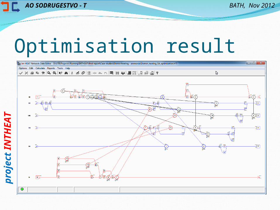
Optimisation result

AO SODRUGESTVO - Tp
roje
ct
INTH
EA
TBATH, Nov 2012
Simplified HEN

AO SODRUGESTVO - Tp
roje
ct
INTH
EA
TBATH, Nov 2012
Reports

AO SODRUGESTVO - Tp
roje
ct
INTH
EA
TBATH, Nov 2012
Reports

AO SODRUGESTVO - Tp
roje
ct
INTH
EA
TBATH, Nov 2012
Reports
AO SODRUGESTVO - Tp
roje
ct
INTH
EA
TBATH, Nov 2012
Related PublicationsA. Garev, S. Boldyryev, O. Arsenyeva, L. Tovazhnyanskyy,
P. Kapustenko. Integration of Ammonia Cooling Cycle in Buildings Heating System with Computer Modeling. Book of Abstracts of CAPE Forum 2012 – Computer Aided Process Engineering. 26-28 March 2012. University of Pannonia, Veszprem, Hungary. p. 22-23.
S. A. Boldyryev, J. J. Klemeš, L. L. Tovazhnyansky, P. O. Kapustenko, A. O. Garev, O. P. Arsenyeva. Integration of ammonia refrigeration cycle to district heating system. Integrated Technologies and Energy Saving, 2012. 2, 76-81 (in Russian).
S. A. Boldyryev, P. O. Kapustenko, L. L. Tovazhnyansky, A. O. Garev, O. Yu. Perevertaylenko, G. L. Khavin, O. P. Arsenyeva, J. J. Klemeš. Ammonia Refrigeration Cycle Integration in Buildings Heating System. Chemical Engineering Transaction, 2012. 29 (2), 1453-1458.

AO SODRUGESTVO - Tp
roje
ct
INTH
EA
TBATH, Nov 2012
AO SODRUGESTVO - Tp
roje
ct
INTH
EA
TBATH, Nov 2012
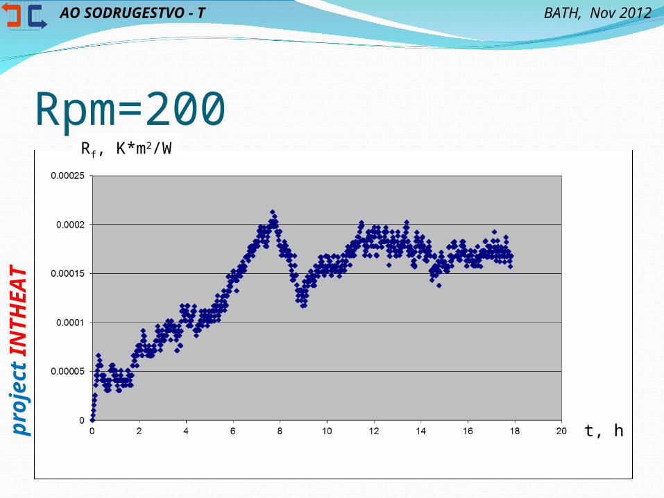
Rpm=200Rf, K*m2/W
t, h

AO SODRUGESTVO - Tp
roje
ct
INTH
EA
TBATH, Nov 2012
Rpm=400Rf, K*m2/W
t, h

AO SODRUGESTVO - Tp
roje
ct
INTH
EA
TBATH, Nov 2012
Rpm=500Rf, K*m2/W
t, h

AO SODRUGESTVO - Tp
roje
ct
INTH
EA
TBATH, Nov 2012
Related PublicationsArsenyeva O.P., Yang M., Crittenden B.,
Kapustenko P.O. Heat transfer surface fouling in plate heat exchangers with enhanced heat transfer. Integrated Technologies and Energy Saving, 2012. 2, 110-111 (in Russian).
Olga P. Arsenyeva, Barry Crittenden, Mangyan Yang, Petro O. Kapustenko. Accounting for the Thermal Resistance of Cooling Water Fouling in Plate Heat Exchangers (submitted to ATE)

AO SODRUGESTVO - Tp
roje
ct
INTH
EA
TBATH, Nov 2012