A.O. SMITH - A4-manuals - Inn · BS EN 806-2: Specification for installations inside buildings...
92
0312266 Innovation has a name. Installation, Service, Maintenance and User Manual Innovo Condensing High-Efficiency Water Heater IR - 12-160/12-200/20-160/20-200/24-245/ IR - 24-285/32-245/32-285/32-380 Water Heaters 1017 - Changes Reserved.
Transcript of A.O. SMITH - A4-manuals - Inn · BS EN 806-2: Specification for installations inside buildings...

0312266
Innovation has a name.
Installation, Service, Maintenance andUser Manual
InnovoCondensing High-EfficiencyWater HeaterIR - 12-160/12-200/20-160/20-200/24-245/IR - 24-285/32-245/32-285/32-380
WaterHeaters
1017 -
Changes
Rese
rved.

A.O. Smith UK, Unit B8 Amstrong Mall,Southwood Business Park, Farnborough, Hampshire GU14 0NRwww.aosmith.co.uk
“A.O. Smith Water Heaters” is a trading name of Advance Services (Sales) Ltd. Reg.
your installer
WaterHeaters

Preface
CopyrightCopyright © 2016 A.O. Smith Water Products Company
All rights reserved.
Nothing from this publication may be copied, reproduced and/or published by means ofprinting, photocopying or by whatsoever means, without the prior written approval of A.O.Smith Water Products Company.
A.O. Smith Water Products Company reserves the right to modify specifications in thismanual.
TrademarksBrand names in this manual are registered trademarks of their respective owners.
WarrantyRefer to the appendix Warranty (see section 13.6) for the warranty provisions.
LiabilityA.O. Smith accepts no liability for claims from third parties caused by:
unauthorized useuse other than stated in this manualuse other than in accordance with the General Conditions registered at the Chamberof Commerce.
For more information, refer to the General Conditions. These are available on request, freeof charge.
We believe that this manual provides you with accurate and complete descriptions of allrelevant components. If you, nonetheless find errors or inaccuracies in this manual, pleaseinform A.O. Smith. This helps us to further improve our documentation.
ComplianceTo safely produce domestic hot water, the design and construction of the Innovo waterheaters is in accordance with:
the European Gas Appliance Directive (GAD).the European Standard for Gas–fired storage water heaters for the production ofdomestic hot water (EN89).The European ECO-Design Directive.The European Energy Labeling Directive
Refer to the appendix Declaration of conformity (see section 13.5).
•••
••
••
0312266_INNOVO_UKUK_V3.0, 2017-02-10 3
RegulationsGas Safety (installations and Use) Regulations 1998 (asamended).It is law that all gas appliances are installed by competent persons, in accordance with theabove regulations. Failure to install appliances correctly could lead to prosecution. It is inyour own interest and that of safety, to ensure that this law is complied with.
The installation of the water heater MUST be in accordance with the relevant requirementsof the Gas Safety Regulations, Building Regulations, IEE Regulations and the Water Supply(water fittings) Regulations. The installation should also be in accordance with anyrelevant requirements of the HSE, local gas region and local authority and the relevantrecommendations of the following documents:
British and European StandardsBS 6891:Installation of low pressure gas pipework of up to 35 mm (R1¼) in domesticpremises (2nd family gas) - Specification. Note: for lager installations see IGE/UP/2below.BS 6798:Specification for installation and maintenance of gas-fired boilers of rated input notexceeding 70 kW net.BS 6644:Specification for installation of gas-fired hot water boilers of rated inputs between 70kW (net) and 1.8 MW (net) (2nd and 3rd family gases).BS 6700:Design, installation, testing and maintenance of services supplying water fordomestic use within buildings and their cartilages - SpecificationsBS EN 806-2:Specification for installations inside buildings conveying water for humanconsumption. Part 2: Design.BS 5546:Specification for installation of hot water supplies for domestic purposes, using gas-fired appliances of rated input not exceeding 70 kW.BS 5440:Flueing and ventilation for gas appliances of rated input not exceeding 70 kW net(1st, 2nd and 3rd family gases).
Part 1: Specification for installation of gas appliances to chimneys and formaintenance of chimneys.Part 2: Specification for installation and maintenance of ventilation for gasappliances.
Institute of Gas Engineers and Managers (IGEM) PublicationsIGE/UP/1:Soundness testing and purging of industrial and commercial gas installations.IGE/UP/1A:Soundness testing and direct purging of small low pressure industrial and commercialnatural gas installations.IGE/UP/2:Gas installation pipework, boosters and compressors on industrial and commercialpremises.IGE/UP/10:Installation of flued gas appliances in industrial and commercial premises.
CIBSE PublicationsGuide G:Public Health Engineering
•
•
•
•
•
•
•
-
-
•
•
•
•
•
4

Contact informationIf you have any comments or questions, please contact:
A.O. Smith Water Products Company
Adress: PO Box 705500 AB VeldhovenThe Netherlands
Telephone: 0870 - AOSMITH (free)0870 - 267 64 84
General: +31 40 294 25 00
Fax: +31 40 294 25 39
E-mail: [email protected]
Website: www.aosmith.co.uk
In the event of problems with your gas, electricity or water supply connections, contactyour supplier.
0312266_INNOVO_UKUK_V3.0, 2017-02-10 5

6

About this manual
ScopeThis manual gives information about safe and correct use of the water heater and howinstallation, maintenance and service activities have to be done correctly. You must obeythe instructions in this manual.
CautionRead this manual carefully before you start the water heater. It can cause personal injuryand damage to the water heater when you do not read the manual and/or do not obeythe instructions.
The purpose of this manual is to:
describe the working principles and layout of the water heaterexplain the safety deviceshighlight possible hazardsdescribe the use of the water heaterdescribe the installation, service and maintenance of the water heater
This manual has two parts:
An User part that describes the correct usage of the water heater.An Installation, Maintenance and Service part, that describes the correct installationand maintenance procedures.
Target groupThe information in this manual applies to three target groups:
usersinstallation engineersservice and maintenance engineers
The User part is intended for the (end) users. The Installation, Maintenance and Servicepart is intended for the installation engineers and the service and maintenance engineers.
Notation conventionsThis manual uses the following text conventions:
Numbers between parentheses e.g. (1), refer to elements in a figure that aredescribed by the text.Texts displayed on the user interface always are shown similar to the characters inthe display, for example parameter 120 or Off.Buttons are always shown between brackets, for example: [ ], [ENTER], [RESET].Cross-references to sections, tables, figures etc. are underlined and written as (seesection "..."). In the digital version, the cross-references function as hyperlinks thatcan be used to navigate through the manual by clicking on them. Example: Safety(see section 2).
c•••••
••
•••
•
•
••
0312266_INNOVO_UKUK_V3.0, 2017-02-10 7

This manual contains the following text styles/symbols for situations that may endangerusers/engineers, cause damage to equipment or need special attention:
NoteA note gives more information on a topic.
CautionObey the caution instructions to prevent damage of the water heater.
WarningObey the warning instructions to prevent danger of personal injury, and serious damageto the water heater.
Document identificationArticle number Language Version
0312266 EN 3.0
ncw
8

Table of Contents
Preface........................................................................................3
Copyright.......................................................................... 3
Trademarks.......................................................................3
Warranty...........................................................................3
Liability.............................................................................3
Compliance....................................................................... 3
Regulations....................................................................... 4
Contact information............................................................5
About this manual....................................................................... 7
Scope............................................................................... 7
Target group..................................................................... 7
Notation conventions.......................................................... 7
Document identification.......................................................8
User part.................................................................. 13
1 Introduction.............................................................................. 15
2 Safety........................................................................................17
3 Interface................................................................................... 19
3.1 Operator interface............................................................ 19
3.1.1 Control Switch..................................................................19
3.1.2 Buttons........................................................................... 20
3.1.3 LCD display..................................................................... 20
3.2 Status of the water heater................................................. 21
3.2.1 Operating modes..............................................................21
3.2.2 Error conditions................................................................22
3.2.3 Service conditions.............................................................22
3.2.4 Anode warning................................................................. 23
4 Use............................................................................................25
4.1 Set a parameter value.......................................................25
4.2 Turn on the water heater...................................................25
0312266_INNOVO_UKUK_V3.0, 2017-02-10 9
4.2.1 Switch to ON mode...........................................................25
4.2.2 Set the water temperature.................................................25
4.3 Turn off the water heater...................................................25
4.3.1 Turn off for a short period..................................................25
4.3.2 Isolate from the mains...................................................... 26
4.3.3 Turn off for a long period...................................................26
Installation, Maintenance and Service part.............. 27
5 Introduction.............................................................................. 29
5.1 About the water heater..................................................... 29
5.2 Working principle..............................................................29
6 Safety........................................................................................31
6.1 Safety instructions............................................................31
6.2 Instructions on the water heater.........................................32
6.3 Safety devices..................................................................33
6.4 Environmental aspects...................................................... 34
6.4.1 Recycling.........................................................................34
6.4.2 Disposal.......................................................................... 34
7 Water heater............................................................................. 35
7.1 Structure of the water heater............................................. 35
8 Installation............................................................................... 37
8.1 Packaging........................................................................37
8.2 Conditions....................................................................... 37
8.2.1 Ambient conditions........................................................... 37
8.2.2 Maximum floor load.......................................................... 37
8.2.3 Water composition............................................................38
8.2.4 Working clearances...........................................................38
8.2.5 Level the water heater...................................................... 38
8.3 Installation diagram..........................................................39
8.4 Water connections............................................................ 40
8.4.1 Cold water connection.......................................................40
8.4.2 Hot water connection........................................................ 40
8.4.3 Circulation connection....................................................... 40
8.5 Condensate drain............................................................. 41
8.6 Gas connection.................................................................41
8.7 Venting system................................................................ 42
8.7.1 C13/C33 concentric systems.............................................. 44
10

8.7.2 C13/C33 parallel systems.................................................. 46
8.7.3 C43/C53/C63 systems.......................................................48
8.8 Electrical connections........................................................49
8.8.1 Preparation......................................................................49
8.8.2 Mains power.................................................................... 50
8.8.3 Optional electrical connections............................................50
8.8.4 Finalization...................................................................... 51
8.9 Commissioning.................................................................51
8.9.1 Filling..............................................................................52
8.9.2 Air pressure differential..................................................... 52
8.9.3 Gas supply pressure..........................................................53
8.9.4 CO2 value........................................................................54
8.9.5 Turn on the water heater...................................................56
8.10 Decommisioning...............................................................56
8.10.1 Turn off the water heater...................................................56
8.10.2 Draining.......................................................................... 56
9 Conversion of gas type.............................................................. 57
10 Settings.....................................................................................59
10.1 Operator interface............................................................ 59
10.2 Parameters......................................................................59
10.3 Hysteresis....................................................................... 61
10.4 Error history.................................................................... 61
10.5 Test cycle........................................................................62
11 Maintenance..............................................................................63
11.1 Performance check........................................................... 63
11.2 Preparation......................................................................64
11.3 Water-side maintenance....................................................64
11.3.1 Descale the tank.............................................................. 64
11.3.2 Clean the condensate drain................................................64
11.4 Gas-side maintenance.......................................................65
11.4.1 Clean the burner.............................................................. 65
11.4.2 Clean the combustion chamber...........................................67
11.4.3 Assemble the burner.........................................................67
11.5 Finalization...................................................................... 68
12 Troubleshooting........................................................................ 71
12.1 Errors and warnings..........................................................71
12.1.1 General errors..................................................................71
0312266_INNOVO_UKUK_V3.0, 2017-02-10 11

12.1.2 Displayed errors............................................................... 73
12.1.3 Warnings.........................................................................80
13 Appendices................................................................................81
13.1 Technical details...............................................................81
13.2 Dimensions......................................................................82
13.3 Gas details...................................................................... 84
13.3.1 Energy labeling................................................................ 85
13.4 Electrical wiring diagram....................................................86
13.5 Declaration of conformity...................................................87
13.6 Warranty.........................................................................88
Index........................................................................................ 91
12

User part
0312266_INNOVO_UKUK_V3.0, 2017-02-10 13

14

1 Introduction
The Innovo water heater stores and heats water for sanitary purposes.
Cold water enters the bottom of the tank through the water inlet (1). The heated waterleaves the tank at the top through the hot water outlet (2). To operate the water heater,the operator interface (3) and control switch (4) are used.
Fig. Innovo water heater
1
2
4
3
1. Water inlet
2. Water outlet
3. Operator interface
4. Control switch
0312266_INNOVO_UKUK_V3.0, 2017-02-10 15

16 User part
2 Safety
A.O. Smith cannot be held responsible for damages or injuries leading back to:
Failure to follow the instructions provided in this manual.Carelessness during use or maintenance of the water heater.
Every user has to study the user part of this manual and has to follow the instructions inthis part of the manual strictly. Do not change the sequence of the actions to be done.This manual has to be available for the user and service engineer all the time.
WarningIf you smell gas:
Shut off the mains gas supply valve!Avoid causing sparks! Do not use any electrical equipment or switch, i.e. notelephones, plugs or bells!No naked flames! No smoking!Open windows and doors!Warn occupants and leave the building!After leaving the building, alert the gas distribution company or yourinstallation engineer.
w ••
••••
CautionDo not store or use chemical substances in the room where the water heater is installedbecause of the risk of explosion and corrosion of the water heater. Some propellants,bleaching agents and degreasing agents etc. disperse of explosive vapors and/or causeaccelerated corrosion. If the water heater is used in a room where such substances arestored or used, the warranty will be void.
CautionInstallation, maintenance and service may only by carried out by a qualified engineer.
CautionThe water heater is not intended for use by persons with reduced physical, sensory ormental capacities, or who lack the necessary experience or knowledge. When the personresponsible for their safety is supervising them or has explained to them how the waterheater should be used, these persons can use the water heater.
CautionThis water heater is not intended to be used by children. Always supervise children, andmake sure that they do not play with the water heater.
NoteRegular maintenance extends the service life of the water heater. To determine thecorrect service interval, the service and maintenance engineer has to do a check on boththe water and gas side of the water heater three months after installation. Based on thischeck, the best service interval can be determined.
••
c
n
0312266_INNOVO_UKUK_V3.0, 2017-02-10 17

18 User part
3 Interface
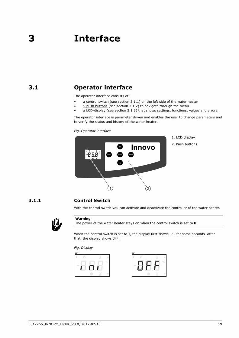
3.1 Operator interfaceThe operator interface consists of:
a control switch (see section 3.1.1) on the left side of the water heater5 push buttons (see section 3.1.2) to navigate through the menua LCD-display (see section 3.1.3) that shows settings, functions, values and errors.
The operator interface is parameter driven and enables the user to change parameters andto verify the status and history of the water heater.
Fig. Operator interface
enter resetmenu
InnovoEXT
21
1. LCD display
2. Push buttons
3.1.1 Control SwitchWith the control switch you can activate and deactivate the controller of the water heater.
WarningThe power of the water heater stays on when the control switch is set to 0.
When the control switch is set to I, the display first shows ini for some seconds. Afterthat, the display shows OFF.
Fig. Display
•••
w
0312266_INNOVO_UKUK_V3.0, 2017-02-10 19

3.1.2 ButtonsThe 5 buttons on the operator panel give access to the menu of the water heater.
Button Function
[ ] Scroll up / Raise
[ ] Scroll down / Lower
[ENTER] Enter / Confirm
[RESET] Reset / Cancel
[MENU] Go to menu
3.1.3 LCD displayThe LCD display shows 7 different symbols around the outer edge of the display and 3characters in the center of the display. The characters represent parameters.
Fig. LCD display
21
1. Characters
2. Symbols
The symbols on the display show visual information about the status of the water heater.
Symbol Explanation
Heat demand present
Water heater in operation
Water heater not in operation - ERROR
Frost protection is activated
Scroll through menuShown on the right side corners of the display
External ON mode is activatedShown on the upper left side corner
20 User part

The user menu parameters are:
Parameter Description Unit/Value Adjustable Range Default
001 Turn the water heater on or off. OFF
ON
Yes OFF - water heater off (OFFmode)
ON - water heater on (ONmode)
OFF
002 Setpoint ON mode ºC Yes 40…max setpoint (1) 65
003 Hysteresis ºC Yes 2…15 10
004 Turn setpoint EXT mode (005)on or off.
ENA
dIS
Yes ENA - Enable
dIS - Disable
dIS
005 (2) Setpoint EXT mode ºC Yes 40…max. setpoint (1) 70
1 - The maximal setpoint (parameter 207) is factory set at 70. A qualified engineer can modify this value.
2 - Parameter 005 will only be accessible when parameter 004 is set on ENA.
3.2 Status of the water heaterDuring operation, the display shows the status of the water heater.
3.2.1 Operating modesThe Innovo has 3 operating modes:
OFF mode (see section 3.2.1.1)ON mode (see section 3.2.1.2)External ON mode (EXT mode) (see section 3.2.1.3)
3.2.1.1 OFF modeUse parameter 001 to switch the water heater to OFF mode.
In the OFF mode the water heater is de-activated. The display shows the characters OFF.
Fig. OFF mode display Fig. Frost protection is activated
To prevent that the water in the system freezes, the frost protection is activated when thewater heater is in OFF mode. The frost protection starts when the temperature of thewater drops below 5°C. The display shows the frost protection symbol.The water heaterwill heat the water to 20°C and then turns back to OFF mode.
3.2.1.2 ON modeUse parameter 001 to switch the water heater to ON mode.
In the ON mode the water heater continuously responds to the heat demand.
When the water heater is heating the water, the display on the operator interfacealternately shows two different screens. The first shows the actual temperature, thesecond shows the setpoint temperature.
When the water heater is not heating the water, only the actual temperature is visible. Thesymbols Heat demand and In operation will not be shown.
•••
0312266_INNOVO_UKUK_V3.0, 2017-02-10 21
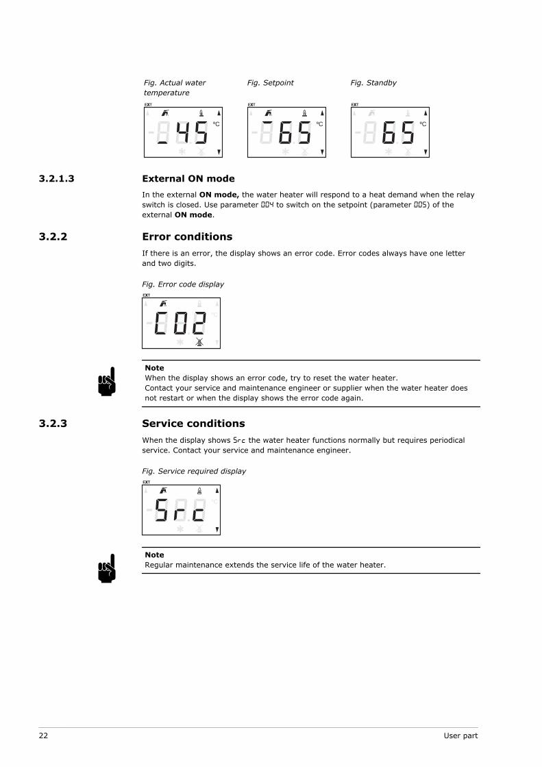
Fig. Actual watertemperature
Fig. Setpoint Fig. Standby
3.2.1.3 External ON modeIn the external ON mode, the water heater will respond to a heat demand when the relayswitch is closed. Use parameter 004 to switch on the setpoint (parameter 005) of theexternal ON mode.
3.2.2 Error conditionsIf there is an error, the display shows an error code. Error codes always have one letterand two digits.
Fig. Error code display
NoteWhen the display shows an error code, try to reset the water heater.Contact your service and maintenance engineer or supplier when the water heater doesnot restart or when the display shows the error code again.
3.2.3 Service conditionsWhen the display shows Src the water heater functions normally but requires periodicalservice. Contact your service and maintenance engineer.
Fig. Service required display
NoteRegular maintenance extends the service life of the water heater.
n
n
22 User part

3.2.4 Anode warningAn anode protects the tank against corrosion. When the anode protection is not active, thedisplay shows Ano. Contact your service and maintenance engineer.
Fig. Anode warning display
NoteIf you ignore the anode warning, the tank protection cannot be guaranteed. The warrantywill be void.n
0312266_INNOVO_UKUK_V3.0, 2017-02-10 23

24 User part

4 Use
4.1 Set a parameter valueTo set a parameter value:
Press [MENU] to access the user menu.Press [ ] or [ ] to scroll to the concerning parameter, refer to Parameters (seesection 3.1.3).Press [ENTER] to select.Use [ ] or [ ] to change the parameter value.
Press [ENTER] to confirm.Press [RESET] to go back to the main menu.
Press [RESET] to leave the user menu.
4.2 Turn on the water heaterTo start the water heater:
Make sure the water heater connects to the mains power supply.Set the control switch on the side of the water (see section 1) heater to I.The display will show ini for about 10 seconds.When the display shows OFF the water heater is ready to use.
4.2.1 Switch to ON modeTo switch to ON mode (see section 3.2.1.2), change parameter 001 to ON, refer to Set aparameter value (see section 4.1).
4.2.2 Set the water temperatureTo change the temperature setpoint:
Adjust parameter 002, refer to Set a parameter value (see section 4.1), orDirectly from ON mode:
Directly use [ ] or [ ] to set the temperature value.Press [ENTER] to confirm.
4.3 Turn off the water heater
4.3.1 Turn off for a short periodTo turn off the water heater for less than 2 months, change parameter 001 to OFF, refer toSet a parameter value (see section 4.1).
The water heater will switch to OFF mode (see section 3.2.1.1) and the frost protection ison.
CautionThe anode protection remains active when the OFF mode is selected.
NoteIf the water heater is in OFF mode for more than 2 months and no water is drained, airbubbles may be formed in the water heater. This can lead to air in the water pipes.
1.2.
3.4.
a.b.
5.
1.2.
3.
••
a.b.
cn
0312266_INNOVO_UKUK_V3.0, 2017-02-10 25
4.3.2 Isolate from the mainsTo isolate the water heater from the mains:
Set parameter 001 to OFF, refer to Set a parameter value (see section 4.1).Wait 1 minute to make sure that the water heater stopped operating.Set the control switch to 0.Disconnect the water heater from the mains by turning the isolator.
4.3.3 Turn off for a long periodWhen the water heater needs to be turned off for more than 2 months, contact yourservice and maintenance engineer to decommission the water heater.
1.2.3.4.
26 User part
Installation, Maintenance and Servicepart
0312266_INNOVO_UKUK_V3.0, 2017-02-10 27

28 User part
5 Introduction
5.1 About the water heaterThe Innovo water heater is intended for heating water for sanitary purposes.
The Innovo is a condensing gas–fired storage water heater with a fan in the air intake. Theflue gasses transfer their heat to the water through an efficient heat exchanger. The waterheater has a concentric venting connector and can function as an open or as a room-sealed water heater.
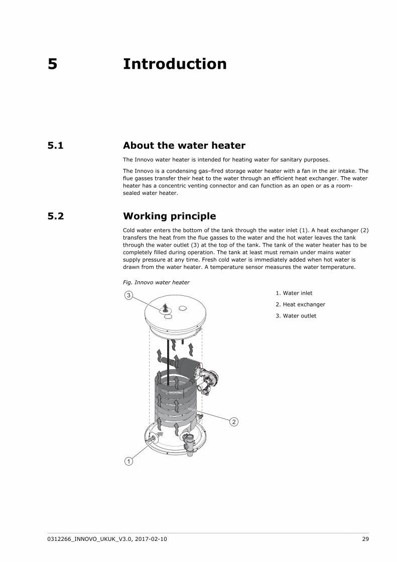
5.2 Working principleCold water enters the bottom of the tank through the water inlet (1). A heat exchanger (2)transfers the heat from the flue gasses to the water and the hot water leaves the tankthrough the water outlet (3) at the top of the tank. The tank of the water heater has to becompletely filled during operation. The tank at least must remain under mains watersupply pressure at any time. Fresh cold water is immediately added when hot water isdrawn from the water heater. A temperature sensor measures the water temperature.
Fig. Innovo water heater
1
3
2
1. Water inlet
2. Heat exchanger
3. Water outlet
0312266_INNOVO_UKUK_V3.0, 2017-02-10 29
When the temperature is too low, the water heater starts a operating cycle:
The controller detects a "heat demand". The icon "Heat demand present" is shown onthe display of the water heater.The fan starts pre-purging.The air proving switch closes when the air pressure differential is sufficient.The hot surface igniter starts pre-ignition.The gas control valve opens and the gas/air mixture is ignited.The water heater heats the water in the tank. The icon "Water heater in operation" isshown on the display of the water heater.When the water temperature reaches the setpoint, the heat demand ends and thecontroller stops the operating cycle.The icons "Heat demand present" and "Water heater in operation" on the display turnoff.The fan starts post-purging.
The operating cycle starts again when a new heat demand is detected.
1.
2.3.4.5.6.
7.
8.
30 Installation, Maintenance and Service part

6 Safety
6.1 Safety instructionsFor safety instructions about the use of the water heater, refer to Safety (see section 2) inthe User part of this manual.
WarningInstallation, maintenance and service must be carried out by a qualified engineer incompliance with the general and local regulations imposed by the gas, water and powersupply companies and the fire brigade. The appliance may only be installed in a room thatcomplies with the requirements stated in national and local ventilation regulations.
WarningLeave the water heater electrically isolated until you are ready to commission it.
CautionThe water heater may only be manoeuvred in an upright position. After unpacking, makesure that the water heater is not damaged.
CautionUse of an incorrect roof or wall-mounted flue terminal can cause the water heater tomalfunction.
CautionDuring installation, obey the instructions delivered with the sets of air supply componentsand the flue gas discharge components. Make sure that the venting system does notexceed the maximum number of 45º and 90º bends and the maximum pipe length.
CautionMake sure that the diameter and length of the gas supply pipe are large enough to supplysufficient capacity to the water heater.
CautionMake sure that the condensate drain is connected to the waste water discharge using anopen connection.
CautionFill the water heater completely before use. Dry firing will damage the water heater.
CautionAfter installation, maintenance or service, you must always check that the appliance isgas tight and make sure that the gas supply pressure, the CO2 value and the air pressuredifferential are correct.If the gas supply pressure is not correct, contact your mains gas supply company. Do notuse the water heater.
CautionTo prevent that you damage the components of the water heater, make sure that it iscompletely stopped operation before you turn off the water heater (see section 4.3). Wait1 minute after you switch the water heater to OFF mode, before you switch the controlswitch to 0.
w
c
0312266_INNOVO_UKUK_V3.0, 2017-02-10 31

CautionThe anode protection remains active when the water heater is in OFF mode and thecontrol switch is set to 0.
NoteAny leakage from the tank and/or connections can cause damage to the immediateenvironment or floors below the level of the boiler room. Install the water heater above awaste water drain or in a suitable metal leak tray.The leak tray must have an appropriate waste water drain and must be at least 5 cmdeep with a length and width at least 5 cm greater than the water heater.
6.2 Instructions on the water heaterThe water heater has some safety instructions on its cover:
The text "Read the installation instructions before installing the appliance".The text "Read the user instructions before putting the appliance into operation".
Also the packaging has some safety instructions:
The text "Read the installation instructions before installing the appliance".The text "Read the user instructions before putting the appliance into operation".The text "The appliance may only be installed in a room that meets the requiredventilation regulations".Some safety pictograms:
CE approved
this way up
fragile
keep dry
maximum stacking height is 1
do not use a trolley
do not use a clamp truck
recycled packaging
n
••
•••
•
32 Installation, Maintenance and Service part
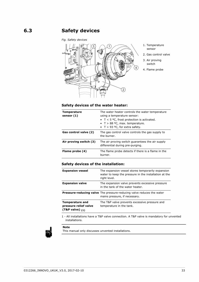
6.3 Safety devices
Fig. Safety devices
1
4
2
31. Temperature
sensor
2. Gas control valve
3. Air provingswitch
4. Flame probe
Safety devices of the water heater:
Temperaturesensor (1)
The water heater controls the water temperatureusing a temperature sensor:
T < 5 ºC, frost protection is activated.T > 88 ºC, max. temperature.T > 93 ºC, for extra safety.
•••
Gas control valve (2) The gas control valve controls the gas supply tothe burner.
Air proving switch (3) The air proving switch guarantees the air supplydifferential during pre-purging.
Flame probe (4) The flame probe detects if there is a flame in theburner.
Safety devices of the installation:
Expansion vessel The expansion vessel stores temporarily expansionwater to keep the pressure in the installation at theright level.
Expansion valve The expansion valve prevents excessive pressurein the tank of the water heater.
Pressure-reducing valve The pressure-reducing valve reduces the watermains pressure, if necessary.
Temperature andpressure relief valve(T&P valve) (1)
The T&P valve prevents excessive pressure andtemperature in the tank.
1 - All installations have a T&P valve connection. A T&P valve is mandatory for unventedinstallations.
NoteThis manual only discusses unvented installations.n
0312266_INNOVO_UKUK_V3.0, 2017-02-10 33

6.4 Environmental aspects
6.4.1 Recycling
The packaging material is environmentally friendly, recyclable and relatively easy todiscard.
6.4.2 Disposal
Old end-of-life appliances contain materials that need to be recycled. When you discarddevices at the end of their service life, you must obey local legislation related to wastedisposal.
Never discard your old device together with regular waste. Put the device into a municipalwaste collection depot for electrical and electronic equipment. If necessary, ask yoursupplier or your service and maintenance engineer for advice.
34 Installation, Maintenance and Service part
7 Water heater
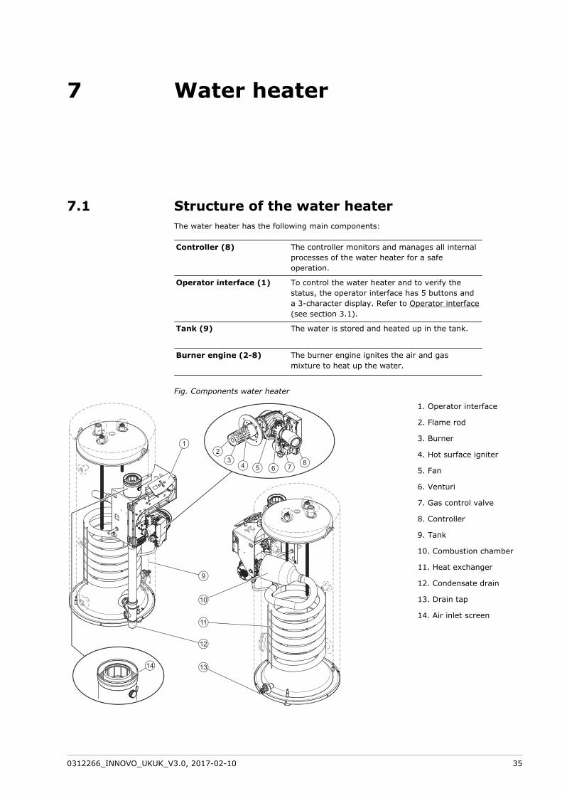
7.1 Structure of the water heaterThe water heater has the following main components:
Controller (8) The controller monitors and manages all internalprocesses of the water heater for a safeoperation.
Operator interface (1) To control the water heater and to verify thestatus, the operator interface has 5 buttons anda 3-character display. Refer to Operator interface(see section 3.1).
Tank (9) The water is stored and heated up in the tank.
Burner engine (2-8) The burner engine ignites the air and gasmixture to heat up the water.
Fig. Components water heater
1
543
2
6 78
9
12
10
11
1314
1. Operator interface
2. Flame rod
3. Burner
4. Hot surface igniter
5. Fan
6. Venturi
7. Gas control valve
8. Controller
9. Tank
10. Combustion chamber
11. Heat exchanger
12. Condensate drain
13. Drain tap
14. Air inlet screen
0312266_INNOVO_UKUK_V3.0, 2017-02-10 35

36 Installation, Maintenance and Service part

8 Installation
WarningThe installation must be done by a qualified person, in compliance with general and localapplicable regulations.
CautionThe water heater may not be used in rooms where chemical substances are stored orused because of the risk of explosion and corrosion of the water heater. Somepropellants, bleaching agents and degreasing agents etc. disperse of explosive vaporsand/or cause accelerated corrosion. If the water heater is used in a room where suchsubstances are stored or used, the warranty will be void.
For more safety instructions, refer to Safety instructions (see section 6.1).
8.1 PackagingA.O. Smith recommends to unpack the water heater at or near its intended location.Remove the packaging material carefully to prevent damage to the water heater.
8.2 ConditionsThe water heater is suitable for room-sealed and for open combustion:
For room-sealed combustion, the air inlet does not depend on the installation site.For open combustion, you must comply with the local applicable directives andventilation regulations for open water heaters.
8.2.1 Ambient conditionsThe installation site must be frost-free. If necessary, adjust the installation site to keep itfrost-free.
Make sure that the ambient conditions are correct to prevent malfunction of the electronicsin the water heater.
Air humidity and ambient temperature
Air humidity Max. 93% RH at + 25 ºC
Ambient temperature Functionality: 0 < T < 40 ºC
8.2.2 Maximum floor loadRefer to the general and electric specifications in the appendices (see section 13) to makesure that the maximum floor load is sufficient for the weight of the water heater.
w
c
••
0312266_INNOVO_UKUK_V3.0, 2017-02-10 37

8.2.3 Water compositionThe water must comply with the regulations for drinking water for human consumption.
Water composition
Hardness(alkaline earth ions)
> 1.00 mmol/l:German hardness > 5.6° dHFrench hardness > 10.0° fHEnglish hardness > 7.0° eHCaCO3 > 100 mg/l
••••
Conductivity > 125 µS/cm
Acidity (pH value) 7.0 < pH value < 9.5
NoteIf the water specifications differ from the specifications in the table, the tank protectioncannot be guaranteed, refer to Warranty.
8.2.4 Working clearancesMake sure that there is sufficient clearance to access the water heater:
100 cm in front of the water heater (AA).50 cm at the left and right side of the water heater (BB).100 cm at the top of the water heater.
Fig. Working clearances
8.2.5 Level the water heaterMake sure that the water heater is level, before installation:
Use a wrench to turn the nut (1) on the adjustable leg clockwise to move the waterheater up.Use a wrench to turn the nut (1) on the adjustable leg anticlockwise to move thewater heater down.
The water heater can move up maximal 20 mm.
NoteMake sure that the working clearance at the top of the water heater does not becomesmaller than 100 cm.
n
•••
•
•
n
38 Installation, Maintenance and Service part

Fig. Adjustable leg water heater
1
8.3 Installation diagramNoteThis manual only discusses unvented installations.
Fig. Installation diagram
1. Pressure relief valve(mandatory if themains waterpressure is too high)
3. T&P valve
4. Stop valve(recommended)
5. Non-return valve
6. Circulation pump(optional)
9. Drain valve
10. Manual gas valve
11. Service stop valve(recommended)
12. Temperature gauge(optional)
13. Condensate drain
14. Draw-off points
15. Expansion valve
16. Expansion vessel
A. Cold water supply
B. Hot water outlet
C. Circulation pipe
D. Gas supply
n
0312266_INNOVO_UKUK_V3.0, 2017-02-10 39

NoteUse this installation diagram when you:
install the water connections (see section 8.4)install the condensate drain (see section 8.5)install the gas connection (see section 8.6)fill the water heater (see section 8.9.1)drain the water heater (see section 8.10.2)
n •••••
8.4 Water connections
8.4.1 Cold water connectionInstall the cold water connection:
Install an approved stop valve (4), as required by the applicable regulations.Install an approved pressure reducing valve (1) to prevent that the pressure in thecold water supply pipe exceeds the maximum working pressure of the tank, 8 bar.Refer to the Technical details (see section 13.1).Install a non-return valve (5).Install an expansion valve (15).Connect the overflow connection of the expansion valve, to an open waste waterpipe.Install an expansion vessel (16).
8.4.2 Hot water connection
NoteInsulate long hot water pipes to prevent unnecessary energy loss.
Install the hot water connection:
Install a stop valve (11) in the hot water outlet pipe for service reasons.If applicable, install a temperature gauge (12).Install a T&P valve (3).
8.4.3 Circulation connectionInstall a circulation pump when an immediate flow of hot water at draw-off points isrequired. This improves comfort and reduces water wastage.
NoteUse the special connection for the circulation pipe on the water heater for a more efficientuse of the water heater.
NoteMake sure that the pump has the correct capacity for the length and resistance of thecirculation system.
Install a circulation pump:
Install a circulation pump (6).Install a non-return valve (5) after the circulation pump to make sure that thedirection of circulation is guaranteed.Install a stop valve (4) before the circulation pump.Install a stop valve (4) after the non-return valve.Connect the circulation pipe.
1.2.
3.4.5.
6.
n1.2.3.
n
1.2.
3.4.5.
40 Installation, Maintenance and Service part
8.5 Condensate drainCautionWhen the condensate drain is not connected to the waste water discharge by an openconnection, this can cause faults.
CautionDo not change the condensate drain or cause any blockage in the condensate drain.
Install the condensate drain:
Install a drain pipe to the condense drain (13) for condensate drainage.Make sure that the slope of the drain pipe is 5 mm/m.Connect the drain pipe through an open connection to the waste water discharge.
8.6 Gas connectionCautionMake sure that the gas supply pipe has the correct diameter and length to supplysufficient capacity to the water heater.
CautionMake sure that the gas supply pipe is clean. Contamination in the pipe can cause damageto the gas control valve, during operation.
CautionInstall the manual gas valve on a spot accessible for the user.
Install the gas connection:
Install a manual gas valve (10) in the gas supply pipe.Make sure that the gas pipe is clean before use. If necessary, remove thecontamination from the pipe.Close the manual gas valve.Install the gas supply pipe to the gas control valve.Make sure that there are no gas leaks.
c
1.2.3.
c
1.2.
3.4.5.
0312266_INNOVO_UKUK_V3.0, 2017-02-10 41
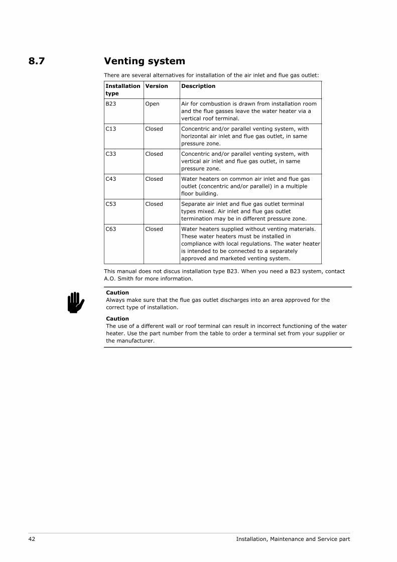
8.7 Venting systemThere are several alternatives for installation of the air inlet and flue gas outlet:
Installationtype
Version Description
B23 Open Air for combustion is drawn from installation roomand the flue gasses leave the water heater via avertical roof terminal.
C13 Closed Concentric and/or parallel venting system, withhorizontal air inlet and flue gas outlet, in samepressure zone.
C33 Closed Concentric and/or parallel venting system, withvertical air inlet and flue gas outlet, in samepressure zone.
C43 Closed Water heaters on common air inlet and flue gasoutlet (concentric and/or parallel) in a multiplefloor building.
C53 Closed Separate air inlet and flue gas outlet terminaltypes mixed. Air inlet and flue gas outlettermination may be in different pressure zone.
C63 Closed Water heaters supplied without venting materials.These water heaters must be installed incompliance with local regulations. The water heateris intended to be connected to a separatelyapproved and marketed venting system.
This manual does not discus installation type B23. When you need a B23 system, contactA.O. Smith for more information.
CautionAlways make sure that the flue gas outlet discharges into an area approved for thecorrect type of installation.
CautionThe use of a different wall or roof terminal can result in incorrect functioning of the waterheater. Use the part number from the table to order a terminal set from your supplier orthe manufacturer.
c
42 Installation, Maintenance and Service part

Fig. Venting systems
0312266_INNOVO_UKUK_V3.0, 2017-02-10 43

8.7.1 C13/C33 concentric systemsUse a wall terminal set or a roof terminal set to install a C13 or a C33 concentric ventingsystem.
Description ConcentricVenting material
Venting materialPP
Venting materialAlu
Manufacture venting material Muelink & Grol Muelink & Grol
Construction Concentric Concentric
Material flue gas outlet PP - Temp. Class T120 Thick walledaluminum
Material air inlet Thin walled galvanizedsteel
Thin walled galvanizedsteel
Diameter flue gas outlet 80 +0,6/-0,6 mm 80 +0,3/-0,7 mm
Diameter air inlet 124 +0,5/-1 mm(Dn 125)
124 +0,5/-1 mm(Dn 125)
Description parts A.O. Smith Partnumber
A.O. Smith Partnumber
Wall terminal setA wall terminal (1), a 500 mm
concentric pipe and a 90° bend
0310759 0302515
Wall terminal 0310757 0302516
Roof terminal setA roof terminal (2), a 1000 mm
concentric pipe and a roof plate
0310755 0305042
Roof terminal 0310753 0304983
Concentric pipe 250 mm 0310740 -
Concentric pipe 500 mm 0310741 0302510
Concentric pipe 1000 mm 0310742 0311448
Concentric pipe 1500 mm - 0311449
Concentric pipe 2000 mm 0310743 -
Concentric pipe telescopic (3) 0310744 -
Concentric pipe to cut 0310745 -
Concentric bend 45° 0310734 0302514
Concentric bend 90° 0310735 0302513
1 - supplied with wall flange and clamping ring
2 - supplied with clamping ring
3 - use this part to connect the air inlet and flue gas outlet to the water heater
44 Installation, Maintenance and Service part
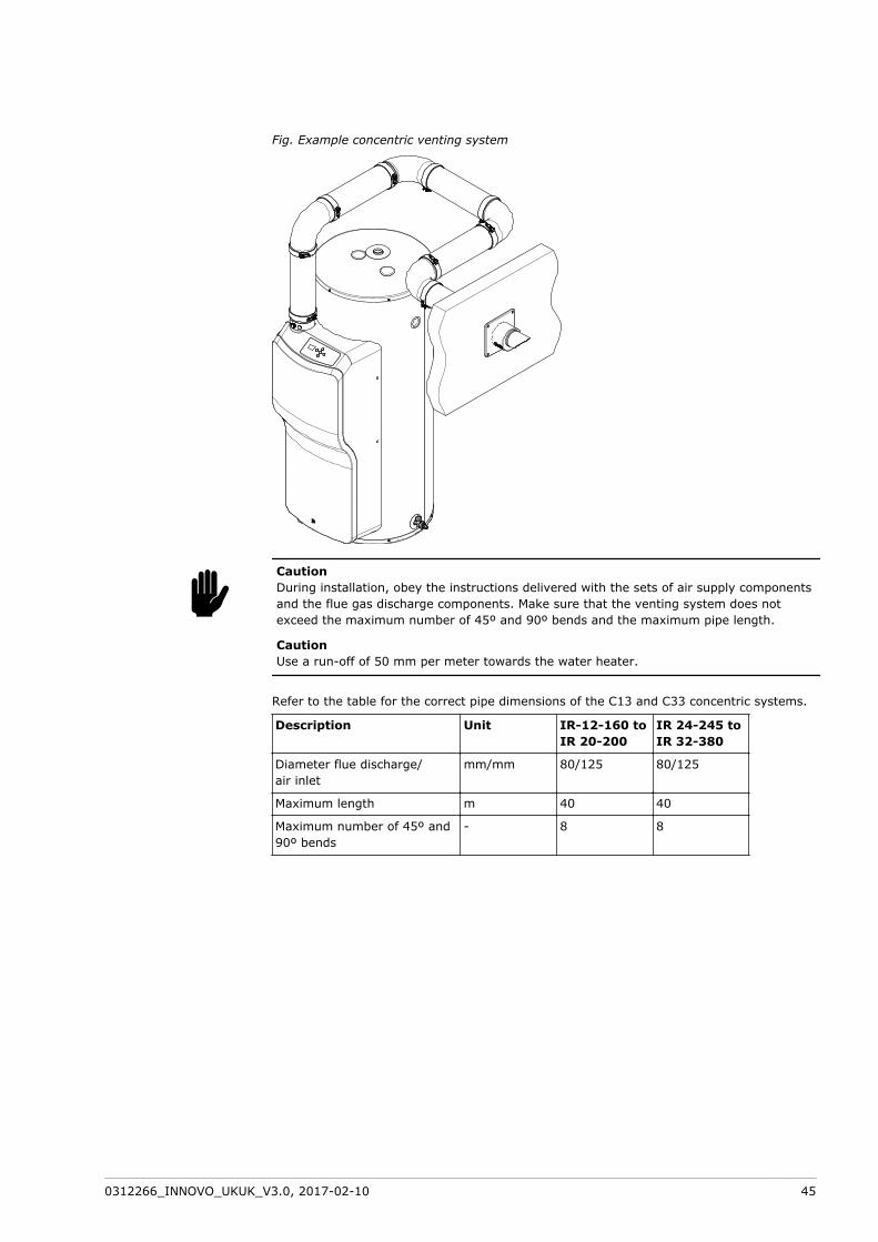
Fig. Example concentric venting system
CautionDuring installation, obey the instructions delivered with the sets of air supply componentsand the flue gas discharge components. Make sure that the venting system does notexceed the maximum number of 45º and 90º bends and the maximum pipe length.
CautionUse a run-off of 50 mm per meter towards the water heater.
Refer to the table for the correct pipe dimensions of the C13 and C33 concentric systems.
Description Unit IR-12-160 toIR 20-200
IR 24-245 toIR 32-380
Diameter flue discharge/air inlet
mm/mm 80/125 80/125
Maximum length m 40 40
Maximum number of 45º and90º bends
- 8 8
c
0312266_INNOVO_UKUK_V3.0, 2017-02-10 45

8.7.2 C13/C33 parallel systemsUse a wall terminal set or a roof terminal set to install a C13 or a C33 parallel ventingsystem.
Description Parallel Ventingmaterial
Venting materialPP
Venting materialAlu
Manufacture venting material Muelink & Grol Muelink & Grol
Construction Parallel Parallel
Material flue gas outlet PP - Temp. Class T120 Thick walledaluminumMaterial air inlet
Diameter flue gas outlet 80 +0,6/-0,6 mm 80 +0,3/-0,7 mm
Diameter air inlet
Description parts A.O. Smith Partnumber
A.O. Smith Partnumber
Wall terminal setA wall terminal (1), an adapter, a
500 mm parallel pipe and a 90° bend
0310730 -
Wall terminal 0310708 0305016
Roof terminal setA roof terminal (2), an adapter, a
1000 mm parallel pipe and a roof
plate
0310712 -
Roof terminal 0310728 0305041
Adapter box concentric toparallel - terminal side
- 0307177
Adapter box concentric toparallel - water heater side
0312209 0312209
Parallel pipe 250 mm 0310718 -
Parallel pipe 500 mm 0310719 0307179
Parallel pipe 1000 mm 0310720 0307180
Parallel pipe 1500 mm - 0307181
Parallel pipe 2000 mm 0310721 -
Parallel pipe telescopic (3) 0310722 -
Parallel bend 45° 0310701 0307182
Parallel bend 90° 0310702 0307183
1 - supplied with wall flange and clamping ring
2 - supplied with clamping ring
3 - use this part to connect the air inlet and flue gas outlet to the water heater
46 Installation, Maintenance and Service part

Fig. Example parallel venting system
Refer to the table for the correct pipe dimensions of the C13 or a C33 parallel ventingsystems.
Description Unit IR-12-160 toIR 20-200
IR 24-245 toIR 32-380
Diameter flue discharge/air inlet
mm/mm 80/80 80/80
Maximum length air inlet m 50 75
Maximum length flue gasoutlet
m 50 75
Lequivalent 45°-bend m 1,1 1,1
Lequivalent 90°-bend m 3,9 3,9
CautionAlways make sure the installation is in compliance with the requirements stated in thistable.
CautionUse a special adapter box to convert the concentric connection on the water heater to aparallel connection. This adapter box converts the 80/125 mm to two times 80 mm. Thisadapter (0312209) can be ordered at your supplier or wholesaler. The use of a differentadapter box may cause the water heater to malfunction.
Calculate the maximum length of the air inlet and the flue gas outlet seperately:
Sum the lengths of the different pipe sections without bends. Ignore the length ofthe adaptor box.Sum the lengths of the bends. Ignore the bend in the adapter box:
Sum 1,1 m for each 45° bend.Sum 3,9 m for each 90° bend.
Sum the lengths of the pipe sections and the lengths of the bends to calculate theoverall length of the air inlet and the flue gas outlet.Adjust the length of the air inlet and/or the flue gas outlet when the overall lengthexceeds the maximum length as stated in the table.
c
1.
2.--
3.
4.
0312266_INNOVO_UKUK_V3.0, 2017-02-10 47

8.7.3 C43/C53/C63 systemsThe length of the air inlet and flue gas outlet is the same for C43, C53 and C63 systems asfor C13 and C33 systems:
Refer to C13/C33 concentric systems (see section 8.7.1) for the maximum pipelengths of concentric systems.Refer to C13/C33 parallel systems (see section 8.7.2) for the maximum pipe lengthsof parallel systems and non-concentric systems.
NoteOnly use a C43 venting system when the common duct is a natural draught chimney. Thecommon duct is part of the building, not a part of the system.
NoteIn a C53 venting system the flue gas terminal must be CE approved and must comply tothe EN 1856-1 requirements.
NoteConnect a C63 venting system to a separately approved and marketed system for thesupply of combustion air and discharge of flue gasses.The flue gas terminal must comply to the EN 1856-1 requirements. The maximumallowable recirculation rate is 10% under wind conditions.
Contact A.O. Smith for more information and/or part numbers of the C43, C53 and C63venting systems.
Concentric systemsRefer to the table for the correct pipe dimensions of the C43, C53 and C63 concentricsystems.
Description Venting materialPP
Venting materialAlu
Manufacture venting material Muelink & Grol Muelink & Grol
Construction Concentric Concentric
Material flue gas outlet PP - Temp. Class T120 Thick walled aluminum
Material air inlet Thin walled galvanizedsteel
Thin walled galvanizedsteel
Diameter flue gas outlet 80 +0,6/-0,6 mm 80 +0,3/-0,7 mm
Diameter air inlet 124 +0,5/-1 mm(Dn 125)
124 +0,5/-1 mm(Dn 125)
Refer to C13/C33 concentric systems (see section 8.7.1) for the A.O. Smith part numbers.The same parts can be used for the C43, C53 and C63 concentric systems.
Parallel and non-concentric systemsRefer to the table for the correct pipe dimensions of the C43, C53 and C63 parallelsystems.
Description Venting materialPP
Venting materialAlu
Manufacture venting material Muelink & Grol Muelink & Grol
Construction Parallel Parallel
Material flue gas outlet PP - Temp. Class T120 Thick walled aluminum
Material air inlet
Diameter flue gas outlet 80 +0,6/-0,6 mm 80 +0,3/-0,7 mm
Diameter air inlet
Refer to C13/C33 parallel systems (see section 8.7.2) for the A.O. Smith part numbers.The same parts can be used for the C43, C53 and C63 parallel systems.
•
•
n
48 Installation, Maintenance and Service part

Use the "adapter box concentric to parallel - water heater side" (part number 0312209) forC63 parallel systems.
8.8 Electrical connections
WarningLeave the water heater electrically isolated until you are ready to commission it.
CautionThe water heater is phase-sensitive. It is absolutely essential to connect the mains live(L) to the live of the water heater and the mains neutral (N) to the neutral of the waterheater.
CautionThere must be no potential difference between neutral (N) and earth (A). Use an isolatingtransformer (see section 8.8.3.1) in the supply circuit when there is a potential difference.
8.8.1 PreparationRemove the cover of the water heater to make the electrical section and the terminal blockvisible:
Use a hex driver to remove the screw (1) at the cover.Hold the cover at the sides.Move the cover to the front and lift it from the water heater.
Fig. Remove the cover
1
wc
1.2.3.
0312266_INNOVO_UKUK_V3.0, 2017-02-10 49
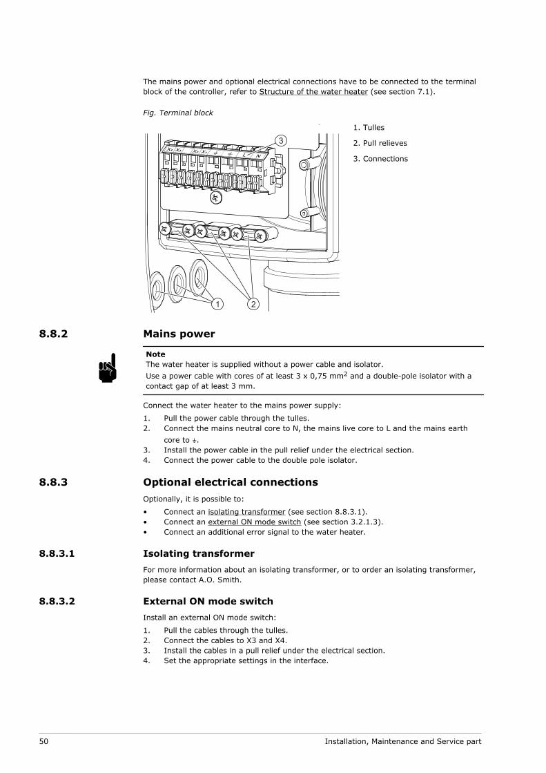
The mains power and optional electrical connections have to be connected to the terminalblock of the controller, refer to Structure of the water heater (see section 7.1).
Fig. Terminal block
1 2
3
1. Tulles
2. Pull relieves
3. Connections
8.8.2 Mains power
NoteThe water heater is supplied without a power cable and isolator.Use a power cable with cores of at least 3 x 0,75 mm2 and a double-pole isolator with acontact gap of at least 3 mm.
Connect the water heater to the mains power supply:
Pull the power cable through the tulles.Connect the mains neutral core to N, the mains live core to L and the mains earthcore to A.Install the power cable in the pull relief under the electrical section.Connect the power cable to the double pole isolator.
8.8.3 Optional electrical connectionsOptionally, it is possible to:
Connect an isolating transformer (see section 8.8.3.1).Connect an external ON mode switch (see section 3.2.1.3).Connect an additional error signal to the water heater.
8.8.3.1 Isolating transformerFor more information about an isolating transformer, or to order an isolating transformer,please contact A.O. Smith.
8.8.3.2 External ON mode switchInstall an external ON mode switch:
Pull the cables through the tulles.Connect the cables to X3 and X4.Install the cables in a pull relief under the electrical section.Set the appropriate settings in the interface.
n1.2.
3.4.
•••
1.2.3.4.
50 Installation, Maintenance and Service part

8.8.3.3 Additional error signal
NoteThe water heater has a relay contact that can be used when an error occurs. The relaycontact is potential–free (maximal 5 A).
Install an additional error signal:
Pull the power cable through the tulles.Connect the cables to X1 and X2.Install the cables in a pull relief under the electrical section.
8.8.4 FinalizationWhen all connections are made, install the cover on the water heater:
Place the cover on the water heater.Use a hex driver to tighten the screw at the front of the cover.
Fig. Install the cover
1
8.9 CommissioningTo commission the water heater:
Fill the water heater (see section 8.9.1)Check the air pressure differential (see section 8.9.2)Check the gas supply pressure (see section 8.9.3)Check the CO2 value (see section 8.9.4)Turn on the water heater (see section 8.9.5)
n1.2.3.
1.2.
1.2.3.4.5.
0312266_INNOVO_UKUK_V3.0, 2017-02-10 51
8.9.1 FillingRefer to the installation diagram (see section 8.3) when you fill the water heater:
Open the stop valve (11) in the hot water supply pipe.If applicable, open the stop valves (4) of the circulation pipe (C).Make sure that the drain valve (9) is closed.Open the nearest hot water draw-off point (14).Open the stop valve (4) of the cold water supply pipe (A). Cold water flows into thewater heater.Fill the water heater until a full water jet flows from the nearest draw-off point. Thewater heater is completely full.Open all draw-off points to bleed the entire installation of air.The water heater is now under water supply pressure.Make sure that no water comes out of the expansion valve (15) or the T&P valve (3).If water comes out:
Examine if the water supply pressure is greater than the specified value in theTechnical details (see section 13.1). If necessary, install a pressure reducingvalve (1).Examine if the expansion valve in the protected cold supply set-up is installedcorrectly and is not defect. If necessary, replace the expansion valve.
8.9.2 Air pressure differentialCheck the air pressure differential across the air pressure switch:
Disconnect hose H of the air proving switch and connect this side of the hose to the+ of the pressure gauge.Disconnect hose L of the air pressure switch and connect this side of the hose to the- of the pressure gauge.Turn the water heater on and set the water heater in OFF mode, refer to Turn onthe water heater (see section 4.2).
NoteMake sure that the water heater is not in ON mode or in External ON mode.
Set parameter 201 to FAn, refer to Settings (see section 10).Read the pressure value from the meter.Compare the measured value to the value from the table (see section 13.1).
NoteWhen the air pressure differential is not correct, refer to Displayed errors (see section12.1.2), error F03.
Set parameter 201 to dIS, refer to Settings (see section 10).Press [RESET].The water heater goes into OFF mode.Set the control switch on the side of the water heater to 0 to turn off the waterheater.Disconnect the pressure gauge.Reconnect the hoses of the air proving switch and the gas valve.
1.2.3.4.5.
6.
7.
8.
-
-
1.
2.
3.
n4.5.6.
n7.8.
9.
10.11.
52 Installation, Maintenance and Service part

Fig. Air pressure differential
HL
8.9.3 Gas supply pressureCheck the gas supply pressure:
Loosen the sealing screw (4) of the test nipple by a few turns.
NoteDo not completely loosen the sealing screw, it can be difficult to retighten it.
Open the gas supply to vent the gas pipes through the test nipple.Connect a pressure gauge to the test nipple as soon as you smell gas.Turn on the water heater (see section 4.2).Set parameter 201 to Hi, refer to Settings (see section 10).If necessary, create a heat demand:
Use a hot water draw-off point to tap water, orRaise the setpoint of the water temperature, refer to Set the watertemperature (see section 4.2.2).
Wait about 1 minute.Use the pressure gauge to read the supply pressure and compare it with the valuefrom the appendix Gas details (see section 13.3).
NoteConsult the mains gas supply company if the supply pressure is not correct. Take thewater heater out of service until the supply pressure is correct, refer to sectionDecommissioning (see section 8.10).
Set parameter 201 to dIS, refer to Settings (see section 10).Press [RESET]. The water heater goes into OFF mode.Set the control switch on the side of the water heater to 0 to turn off the waterheater.Shut off the gas supply.Disconnect the pressure gauge.Tighten the sealing screw in the test nipple.
1.
n2.3.4.5.6.
--
7.8.
n9.10.11.
12.13.14.
0312266_INNOVO_UKUK_V3.0, 2017-02-10 53

Fig. Gas supply pressure
4
1
3
2
1. Adjuster screw
2. Gas control valve
3. Gas supply pipe
4. Sealing screw
8.9.4 CO2 value
Check the CO2 value:
Open the gas supply.Remove the cap (1) from the test nipple (2) of the flue gas outlet pipe.Place the measurement probe of the CO2 meter in the test nipple of the flue gasoutlet pipe.Turn on the water heater, refer to Turn on the water heater (see section 4.2).Set parameter 201 to Hi, refer to Settings (see section 10).
1.2.3.
4.5.
54 Installation, Maintenance and Service part

If necessary, create a heat demand:Use a hot water draw-off point to tap water, orRaise the setpoint of the water temperature, refer to Set the watertemperature (see section 4.2.2).
Wait until the measured value on the CO2 meter remains stable for some time. Thiscan take several minutes.Compare the full load measured value to the value from the appendix Gas details(see section 13.3).The CO2 value at full load must be within ±1.0 vol% of the CO2 value stated in thetable.
CautionWhen the CO2 value is not correct, refer to General errors (see section12.1.1), CO2 value (at full load) is not correct.Do not use the water heater when the CO2 value is not correct and this is notcaused by the restrictor, venturi, venting system or gas category:
Switch off the appliance.Turn off the gas supply.Put the cover back on the water heater.Contact your supplier.
c••••
Set parameter 201 to Lo, refer to section Settings (see section 10).Wait until the measured value on the CO2 meter remains stable for some time. Thiscan take several minutes.Compare the measured value to the value measured under full load.The CO2 value at partial load must be within ±0.3 vol% of the CO2 value measuredunder full load.If necessary, use a hex driver to adjust the adjuster screw until the CO2 value iscorrect.
Turn the screw clockwise for a higher CO2 value.Turn the screw anticlockwise for a lower CO2 value.
If applicable, set the temperature value back to the original value (parameter 002).Set parameter 201 to dIS, refer to Settings (see section 10).Press [RESET]. The water heater goes into OFF mode.Set the control switch on the side of the water heater to 0 to turn off the waterheater.Remove the measurement probe of the CO2 meter from the test nipple and place thecap (1) back on the nipple (2).Shut off the gas supply.
Fig. CO2 value
12
1. Cap
2. Test nipple
6.--
7.
8.
9.10.
11.
12.
a.b.
13.14.15.16.
17.
18.
0312266_INNOVO_UKUK_V3.0, 2017-02-10 55
8.9.5 Turn on the water heaterRefer to the procedure in the user part to Turn on the water heater (see section 4.2).
8.10 DecommisioningTo decommission the water heater:
Turn off the water heater (see section 8.10.1)Drain the water heater (see section 8.10.2)
8.10.1 Turn off the water heaterRefer to the procedure in the user part to Turn off the water heater (see section 4.3) andisolate the water heater from the mains power supply.
8.10.2 DrainingRefer to the installation diagram (see section 8.3) when you drain the water heater:
Close the manual gas valve (10).If applicable, close the service stop valve (11) in the hot water pipe.Close the stop valve (10).Open the drain valve (9).Aerate the entire installation of air until the water heater is completely drained.
1.2.
1.2.3.4.5.
56 Installation, Maintenance and Service part

9 Conversion of gas type
CautionConversion of the water heater may only be carried out by a qualified person.
Use a special conversion kit to converse the water heater when:
The water heater has to operate on a different family of gases (liquid petroleum gasor natural gas).The water heater has to operate on a gas category other than that for which thewater heater has been configured at the factory.
You can order the conversion kit you need from the supplier of your water heater. Theconversion kit contains all the parts needed to do the conversion and a description of howto do the conversion.
The following conversions are possible:
Conversion from natural gas to LPG.Conversion from LPG to natural gas.Conversion from natural gas to natural gas.
CautionAfter the conversion, make sure that the water heater is gas-tight. Make sure that thesupply pressure, the gas control valve pressure, the CO2 value and the switching pressurehave the correct value.
c•
•
•••
c
0312266_INNOVO_UKUK_V3.0, 2017-02-10 57

58 Installation, Maintenance and Service part

10 Settings
10.1 Operator interfaceThe operator interface is parameter driven and enables the user to change parameters andto verify the status and history of the water heater.
When you press [MENU] once, parameters 001 to 120 can be accessed. All otherparameters can be accessed when you press [MENU] for 10 seconds.
For more information about how to use the operator interface, refer to Operator interface(see section 3.1) and Set a parameter value (see section 4.1).
10.2 ParametersParameter Description Unit/Value Adjustable Range Default
001 Turn the water heater on or off. Off
ON
Yes Off - water heater off(OFF mode)
ON - water heater on(ON mode)
Off
002 Setpoint ON-mode ºC Yes 40…max setpoint (1) 65
003 Hysteresis ºC Yes 2…15 10
004 Turn setpoint EXT-mode (005)on or off.
ENA
dIS
Yes ENA - Enable
dIS - Disable
dIS
005 (2) Setpoint EXT-mode 2 ºC Yes 40…max. setpoint (1) 70
101/
102
Actual water temperature °C No 0…99 -
109 Actual Ionisation signal μA No 0…15 -
112 Status EXT contact OPE
CLo
No OPE - EXT contact open
CLo - EXT contact closed
-
113 Status air proving switch OPE
CLo
No OPE – air proving switch open
CLo - air proving switch closed
-
115 Actual fan speed x10 rpm No 0…990 -
0312266_INNOVO_UKUK_V3.0, 2017-02-10 59

Parameter Description Unit/Value Adjustable Range Default
116 Status burner Initialization
Reset
Stand-by
Pre-purge (1)
Pre-Purge (2)
Pre-Ignition
Ignition
Flame check
Burn
Post-Burn
Post-Purge (1)
Post-Purge (2)
Blocking
Lockout
Warning
Burner Boot
No 0 - Initialization
1 - Reset
2 - Stand-by
3 - Pre-purge(part 1)
4 - Pre-Purge(part 2)
5 - Pre Ignition
6 - Ignition
7 - Flame check
8 - Burn
9 - Post Burn
10 - Post Purge (part 1)
11 - Post Purge (part 2)
12 - Blocking
13 - Lockout
14 - Warning
15 - Burner Boot
-
117 Actual error number # No C02…S13
--- - no error
-
120 Time left till service reminderappears on display
Months
Days
No ≥ 1 Month = 01 - 36
< 1 Month = 01d - 31d
12
201 Test cycle dIS
FAn
Lo
Ign
Hi
rEg
Yes dIS - leave test cycle
FAn - pre-purge on ignitionspeed
Lo - burn on partial load
Ign - burn on ignition speed
Hi - burn on full load
rEg - t.b.d.
dIS
202 Turn the power anode warningon or off.
Off
ON
Yes Off - power anodes deactivated
ON - power anodes activated
ON
203 Minimum fan speed ×10 rpm No 0…990 -
204 Ignition fan speed ×10 rpm No 0…990 -
205 Maximum fan speed ×10 rpm No 0…990 -
207 Maximum setpoint ºC No 40…85 70
208 Minimum load % Yes 0…50
0 and 1 = minimum load
50 = 50% between minimumload and maximum load
0
211 Service reminder Off
ON
rst
Yes Off - service reminder off
ON - service reminder on
rst - reset service reminder
ON
212 Setting service interval Months Yes 0…36 12
270 Last lock-out error # No C02…S14
--- - no error
-
271 Interval between last lock-outand read-out.
Minutes
Hours
Days
Weeks
No 00n...59n = 0 till 59 minutes
01h...23h = 1 till 23 hours
01d...06d = 1 till 6 days
01...63 = 1 till 63 weeks
-
272 Last blocking error # No C02…S14
--- - no error
-
60 Installation, Maintenance and Service part

Parameter Description Unit/Value Adjustable Range Default
273 Interval between last blockingerror and read-out.
Minutes
Hours
Days
Weeks
No 00n...59n = 0 till 59 minutes
01h...23h = 1 till 23 hours
01d...06d = 1 till 6 days
01...63 = 1 till 63 weeks
-
274 Number of flame failures # No 0…990 -
275 Number of successful ignitions ×100 No 0…990 -
276 Number of failed ignitions # No 0…990 -
277 Total of actual days that controlis active
×10 days No 0…990 -
278 Total of actual burning days ×10 days No 0…990 -
281 Selection code # No 0…990 -
1 - The maximal setpoint (parameter 207) is factory set at 70. A qualified engineer can modify this value.
2 - Parameter 005 will only be accessible when parameter 004 is set on ENA.
NoteWhen parameter 202 is set to Off, the anode warning Ano will not be shown on thedisplay. Also when there is a problem with the anode protection, this warning will not beshown. The tank protection cannot be guaranteed. The warranty will be void.
10.3 HysteresisThe water heater does not start immediately when the water temperature is below thetemperature setpoint. To prevent that the water heater switches on and off too often,there is a margin; the hysteresis.
The standard hysteresis is 10 °C. Thus, the water heater starts to heat up when the watertemperature is 10 °C below the temperature setpoint. Use parameter 003 to change thehysteresis.
10.4 Error historyThe control unit automatically stores data of occurred errors and failed actions of the waterheater. The error history can be used to analyse the water heater and to find the causes ofthe errors and failed actions.
Use parameters 270 till 273 to read the errors. Use parameters 274 till 277 to read theappliance history, refer to Parameters (see section 10.2).
n
0312266_INNOVO_UKUK_V3.0, 2017-02-10 61

10.5 Test cycleThe test cycle can be used to activate the test modes. These test modes can, for example,be used to set the CO2 value at full and at partial load or to check the air pressuredifferential.
Use parameter 201 to activate the test cycle.
The test cycle is shown on the display. Each test setting can be recognized by the firstletter on the display.
Fig. Example Hi-setting test cycle Fig. Example Lo-setting test cycle
62 Installation, Maintenance and Service part
11 Maintenance
The water heater needs maintenance at least once a year. The maintenance interval isdetermined by the water quality, the average burning time each day and the set watertemperature.
On the operator interface, the maintenance interval can be set as a reminder. The displayshows Src when the pre-set interval has elapsed.
To determine the correct interval, A.O. Smith recommends to do a system check on boththe water and the gas side, three months after installation.
NoteDo maintenance to maintain an effective and efficient transfer of heat to the water. Thissignificantly increases the service life of the water heater.
NoteWhen needed, spare parts can be ordered. To be sure that you receive the correct spareparts, look at the data plate for the full serial number, the water heater model, and theused gas category. Use this information when you order the spare parts.
Do the following maintenance activities:
Performance check (see section 11.1)Water side maintenance (see section 11.3)Gas side maintenance (see section 11.4)Finalization (see section 11.5).
NoteFor maintenance purposes, a special gasket and mounting set can be ordered at yoursupplier. This kit contains the necessary gaskets, bolts and washers. Look at the dataplate for the correct ordering information.
11.1 Performance checkCheck if the performance of all components is correct:
Make sure that the water heater operates the operating cycle correctly.Make sure that the color of the flame is blue.If applicable, make sure that the T&P valve operates correctly.Open the T&P valve pressure relief and make sure that water spurt out.
WarningHot water can come out of the T&P valve.
Make sure the pressure relief connection of the inlet security group operatescorrectly.Open this pressure relief and make sure that water spurt out.Remove the cover from the water heater, refer to Installation (see section 8.8.1).Make sure that the condensate drain operates correctly.If necessary, remove any contamination.Make sure that there are no leaks in the venting system.Make sure the air pressure differential is correct, refer to Air pressure differential(see section 8.9.2).
n
••••
n
1.2.3.
w4.
5.6.
7.8.
0312266_INNOVO_UKUK_V3.0, 2017-02-10 63
Make sure the gas supply pressure is correct, refer to Gas supply pressure (seesection 8.9.3).Make sure the CO2 value is correct, refer to CO2 value (see section 8.9.4).
11.2 PreparationIsolate the water heater from the mains (see section 4.3.2) before you start maintenancetasks.
11.3 Water-side maintenanceTo do water side maintenance:
Descale the tank (see section 11.3.1)Clean the condensate drain (see section 11.3.2)
11.3.1 Descale the tankTo descale and clean the tank:
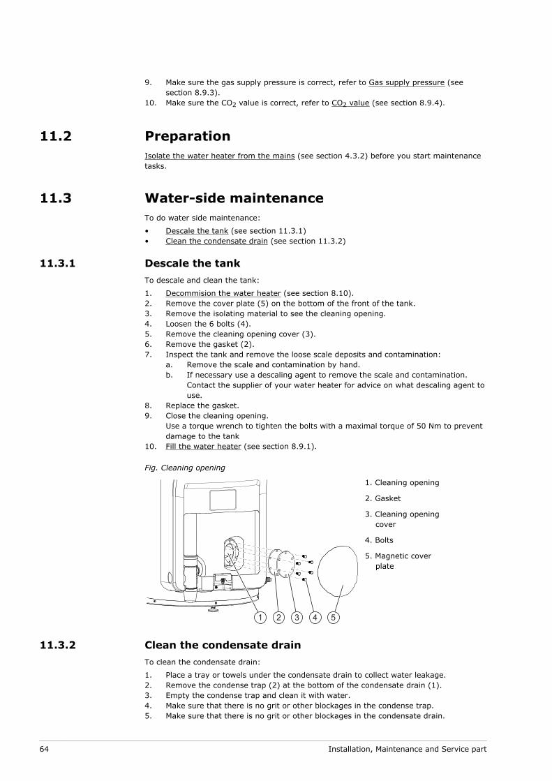
Decommision the water heater (see section 8.10).Remove the cover plate (5) on the bottom of the front of the tank.Remove the isolating material to see the cleaning opening.Loosen the 6 bolts (4).Remove the cleaning opening cover (3).Remove the gasket (2).Inspect the tank and remove the loose scale deposits and contamination:
Remove the scale and contamination by hand.If necessary use a descaling agent to remove the scale and contamination.Contact the supplier of your water heater for advice on what descaling agent touse.
Replace the gasket.Close the cleaning opening.Use a torque wrench to tighten the bolts with a maximal torque of 50 Nm to preventdamage to the tankFill the water heater (see section 8.9.1).
Fig. Cleaning opening
1 2 3 4 5
1. Cleaning opening
2. Gasket
3. Cleaning openingcover
4. Bolts
5. Magnetic coverplate
11.3.2 Clean the condensate drainTo clean the condensate drain:
Place a tray or towels under the condensate drain to collect water leakage.Remove the condense trap (2) at the bottom of the condensate drain (1).Empty the condense trap and clean it with water.Make sure that there is no grit or other blockages in the condense trap.Make sure that there is no grit or other blockages in the condensate drain.
9.
10.
••
1.2.3.4.5.6.7.
a.b.
8.9.
10.
1.2.3.4.5.
64 Installation, Maintenance and Service part

Make sure that there is no grit or other blockages in the drain pipe (3).Make sure that the slope of the drain pipe is correct; 5 mm/m.Install the condense trap onto the condensate drain.
Fig. Condensate drain
123
1. Condensate drain
2. Condense trap
3. Drain pipe
11.4 Gas-side maintenanceDo gas side maintenance when the water heater does not operate correctly, the airpressure differential is not correct and/or the CO2 value is not correct.
To do gas side maintenance:
Clean the burner (see section 11.4.1)Clean the combustion chamber (see section 11.4.2)
11.4.1 Clean the burnerRemove the burner engine:
Close the gas control valve, refer to Installation diagram (see section 8.3).Disconnect all plugs from the burner engine (1).Disconnect the gas supply pipe (2).Loosen the two bolts (3) to disconnect the burner engine (4) from the adapter.Take the burner engine out of the water heater.
Fig. Remove the burner engine
2 1
4
3
1. Plugs on burnerengine
2. Gas supply pipe
3. Bolts
4. Burner engine
6.7.8.
••
1.2.3.4.5.
0312266_INNOVO_UKUK_V3.0, 2017-02-10 65
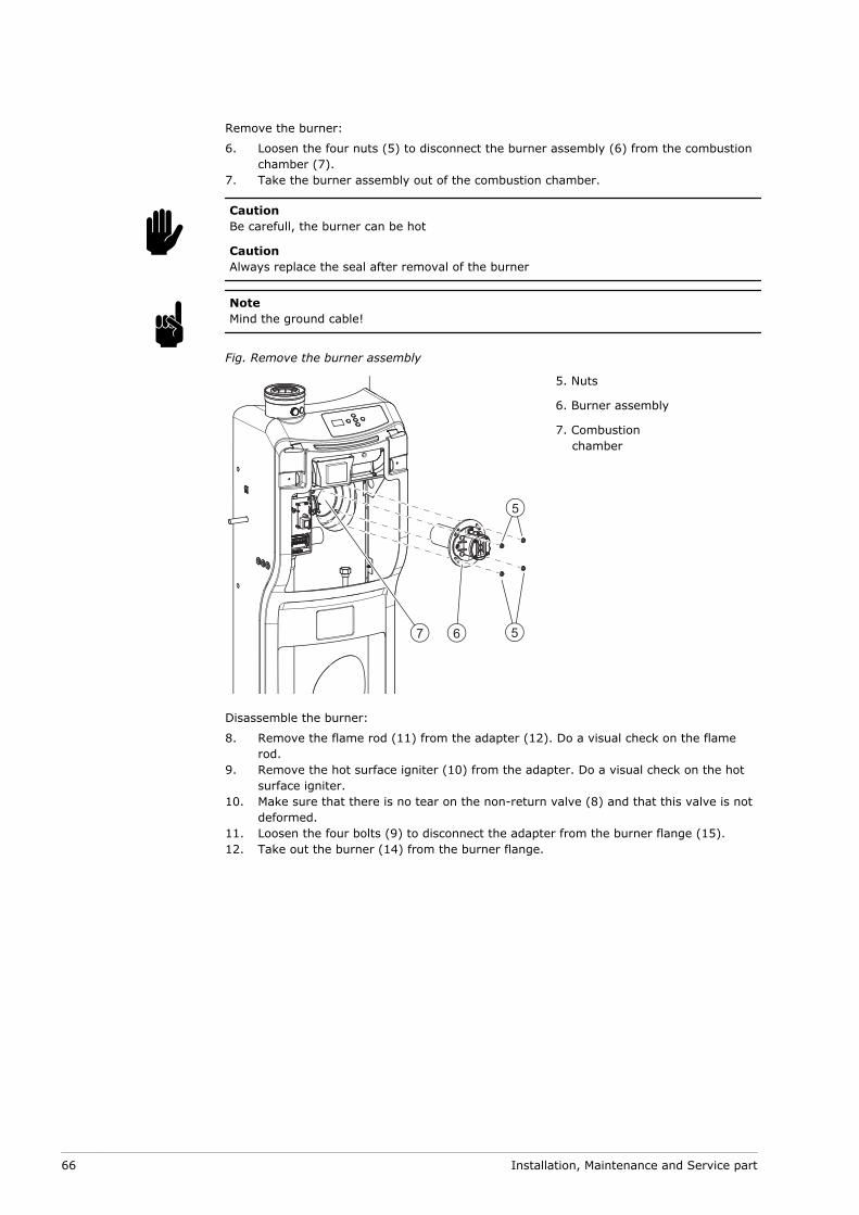
Remove the burner:
Loosen the four nuts (5) to disconnect the burner assembly (6) from the combustionchamber (7).Take the burner assembly out of the combustion chamber.
CautionBe carefull, the burner can be hot
CautionAlways replace the seal after removal of the burner
NoteMind the ground cable!
Fig. Remove the burner assembly
67 5
5
5. Nuts
6. Burner assembly
7. Combustionchamber
Disassemble the burner:
Remove the flame rod (11) from the adapter (12). Do a visual check on the flamerod.Remove the hot surface igniter (10) from the adapter. Do a visual check on the hotsurface igniter.Make sure that there is no tear on the non-return valve (8) and that this valve is notdeformed.Loosen the four bolts (9) to disconnect the adapter from the burner flange (15).Take out the burner (14) from the burner flange.
6.
7.
c
n
8.
9.
10.
11.12.
66 Installation, Maintenance and Service part

Fig. Disassemble the burner assembly
8
10
11
9
9
12
13
14
158. Non return
valve
9. Bolts
10. Hot surfaceigniter
11. Flame rod
12. Adapter
13. Gasket
14. Burner
15. Burnerflange
Use compressed air to remove all contamination from the outside to the inside of theburner (7).
11.4.2 Clean the combustion chamberUse a vacuum cleaner and a soft brush to clean the combustion chamber (1) of the heatexchanger.
Fig. Combustion chamber
1
11.4.3 Assemble the burnerAssemble the burner again when the burner and the combustion chamber both arecleaned.
NoteBefore reassembly replace the gasket, bolts and washers. You can order a special gasketand mounting set at your supplier. Look at the data plate for the correct orderinginformation.
n
0312266_INNOVO_UKUK_V3.0, 2017-02-10 67
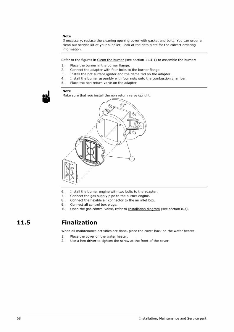
NoteIf necessary, replace the cleaning opening cover with gasket and bolts. You can order aclean out service kit at your supplier. Look at the data plate for the correct orderinginformation.
Refer to the figures in Clean the burner (see section 11.4.1) to assemble the burner:
Place the burner in the burner flange.Connect the adapter with four bolts to the burner flange.Install the hot surface igniter and the flame rod on the adapter.Install the burner assembly with four nuts onto the combustion chamber.Place the non return valve on the adapter.
NoteMake sure that you install the non return valve upright.
!
Install the burner engine with two bolts to the adapter.Connect the gas supply pipe to the burner engine.Connect the flexible air connector to the air inlet box.Connect all control box plugs.Open the gas control valve, refer to Installation diagram (see section 8.3).
11.5 FinalizationWhen all maintenance activities are done, place the cover back on the water heater:
Place the cover on the water heater.Use a hex driver to tighten the screw at the front of the cover.
1.2.3.4.5.
n
6.7.8.9.10.
1.2.
68 Installation, Maintenance and Service part
After that:
Fill the water heater (see section 8.9.1).Make sure the air pressure differential is correct, refer to Air pressure differential(see section 8.9.2).Make sure the gas supply pressure is correct, refer to Gas supply pressure (seesection 8.9.3).Make sure the CO2 value is correct, refer to CO2 value (see section 8.9.4).Turn on the water heater (see section 4.2).Set parameter 211 to rst, refer to Settings (see section 10).Press [RESET].The water heater goes to OFF mode.
3.4.
5.
6.7.8.9.
0312266_INNOVO_UKUK_V3.0, 2017-02-10 69

70 Installation, Maintenance and Service part

12 Troubleshooting
12.1 Errors and warningsThe water heater can have three different kinds of errors and warnings:
General errors (see section 12.1.1), which are not displayedDisplayed errors (see section 12.1.2), which are divided in two different groups:
Lock out errors: when the cause is removed, you can reset the error to resumeoperation. The displayed code and the back-light of the display blink.Blocking errors: when the cause is removed, the error resets automatically toresume operation. The code is displayed continuously and the back-light of thedisplay blinks.
Displayed warnings (see section 12.1.3)
NoteIt is possible to view the error history of the water heater, refer to Error history (seesection 10.4).
12.1.1 General errors
NoteFor the coding of the connections, refer to the Electrical wiring diagram (see section13.4).
Indication Cause Measure
Gas smell There is a gas leak Close the mains gas valve at once.Do not operate any switches.No naked flames.Ventilate the boiler room.Immediately contact your installationengineer or your local gas company.
•••••
The display is off The water heater is off. Turn on the water heater (see section 4.2).
There is no supply voltage. Make sure that:the control switch is set to I.the isolator is in ON position.there is power on the isolator.there is power to the electrical connectorblock.
The measured voltage must be230 VAC (-15%, +10%).
••••
Defective fuse(s) Replace the fuse(s).
••
-
-
•
n
n
0312266_INNOVO_UKUK_V3.0, 2017-02-10 71
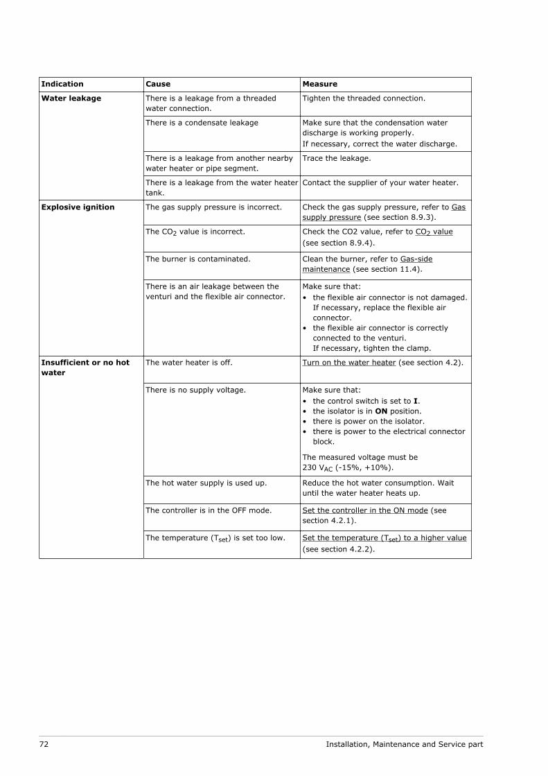
Indication Cause Measure
Water leakage There is a leakage from a threadedwater connection.
Tighten the threaded connection.
There is a condensate leakage Make sure that the condensation waterdischarge is working properly.If necessary, correct the water discharge.
There is a leakage from another nearbywater heater or pipe segment.
Trace the leakage.
There is a leakage from the water heatertank.
Contact the supplier of your water heater.
Explosive ignition The gas supply pressure is incorrect. Check the gas supply pressure, refer to Gassupply pressure (see section 8.9.3).
The CO2 value is incorrect. Check the CO2 value, refer to CO2 value(see section 8.9.4).
The burner is contaminated. Clean the burner, refer to Gas-sidemaintenance (see section 11.4).
There is an air leakage between theventuri and the flexible air connector.
Make sure that:the flexible air connector is not damaged.If necessary, replace the flexible airconnector.the flexible air connector is correctlyconnected to the venturi.If necessary, tighten the clamp.
•
•
Insufficient or no hotwater
The water heater is off. Turn on the water heater (see section 4.2).
There is no supply voltage. Make sure that:the control switch is set to I.the isolator is in ON position.there is power on the isolator.there is power to the electrical connectorblock.
The measured voltage must be230 VAC (-15%, +10%).
••••
The hot water supply is used up. Reduce the hot water consumption. Waituntil the water heater heats up.
The controller is in the OFF mode. Set the controller in the ON mode (seesection 4.2.1).
The temperature (Tset) is set too low. Set the temperature (Tset) to a higher value(see section 4.2.2).
72 Installation, Maintenance and Service part

Indication Cause Measure
CO2 value (at full load)is not correct
The unit is not set for the correct gastype
Make sure that the gas type correspondswith the information on the rating plateMake sure if the venturi restrictor has thecorrect diameter, refer to Gas details (seesection 13.3).
•
•
Contaminated venturi Remove any contamination from the venturiinlet.
Leakage between venturi and flexibleventuri connector
Make sure that the flexible venturiconnector is not damaged.If necessary replace the flexible venturiconnectorMake sure that the flexible venturiconnector is correctly connected.If necessary, tighten the clamp.
•
•
Recirculation of flue gases Make sure that the CO2-value measuredin the flue gas outlet is correct, refer toCO2 value (see section 8.9.4).Make sure that the CO2 value measuredin the air inlet is below 0.5 vol%.If necessary, reconnect the ventingsystem and change the necessary seals.
•
•
•
12.1.2 Displayed errors
NoteFor the coding of the connections, refer to the Electrical wiring diagram (see section13.4).
NoteContact your service and maintenance engineer if the error persists.
Code and description Cause Measure
C02 (lock out error)Control error
Error message from thecontroller
Incorrect reference voltage from theAD converter.EEPROM read error.50 Hz error.Internal communication error.Gas control valve relay error.Safety relay error.Ignition relay error.RAM error.EEPROM error.EEPROM content does not match thesoftware version.Processor software error.Ionisation circuit error
•
•••••••••
••
Make sure that the wiring/flame probeare not damaged. If necessary, replacethe wiring/flame probe.Make sure that the flame probe is notbend. If necessary, replace the flameprobe.Reset the controller.If the error reappears, make sure thatthe frequency of the power supply is 50Hz (-1, +1 Hz).If the frequency is not correct, contactyour service and maintenance engineer.If the frequency is correct and the errorreapers, replace the controller.Make sure that there is no "floating zero".If necessary, install an isolatingtransformer.
•
•
••
•
•
•
C03 (blocking error)Control error
More then 7 resets detected in a shortperiod.
Wait for the error to disappear (maximal 1hour).If the error does not disappear, replace thecontroller
C04 (blocking error)Control error
This error appears when the controllerand/or display is replaced.Incorrect selection of the water heater.
Turn the water heater OFF and ON. Whenthe error reappears contact your supplier.
n
0312266_INNOVO_UKUK_V3.0, 2017-02-10 73

Code and description Cause Measure
C05 (blocking error)Control error
Content EEPROM not correct. Reset the controller.If the error reappears, contact your supplier.
E01 (blocking error)Temperature error
The temperature in the tank is above90ºC.
Tap off water, so the temperature dropsin the water heater.Reset the controller.Make sure that there is no scale on thetemperature sensor. If necessary, replacethe sensor.
•
••
E03 (lock out error)Temperature error
Temperature difference, between sensor1 and sensor 2, is more then 10ºC, forat least 60 seconds.
Make sure that the sensor wiring isconnected and not damaged. Reset thecontroller.If necessary replace the sensor and/orwiring if the error reappears.
E05 (lock out error)Control error
Control was in a blocking error for atleast 20 hours.
Press [RESET] to reset the water heater.If the error reappears:
Find the cause of the blocking error(parameter 272).Remove the blockage and reset thecontroller.
If the error reappears, replace thecontroller.
•
•
•
F01 (blocking error)Control error
Live and neutral are connected thewrong way around.
Make sure that the live and neutral areconnected correctly and rectify if necessary.
Floating zero is present. Install an isolating transformer.
F02 (lock out error)Fan error
Fan does not run oncorrect speed
Damaged or disconnected wiring. Make sure that the wiring between thefan and the controller is connected andnot damaged.If necessary, replace the wiring. Resetthe controller when the wiring isreconnected
•
•
Contaminated or blocked fan. Make sure that the motor and/or rotor ofthe fan are not dirty or blocked.If necessary remove the dirt and/orblockage.Reset the controller.Make sure that the rotor of the fan canrotate freely and reset the controller.
•
•
••
Due to a drop in supply voltage, the fanwill not run at the correct speed.
Make sure that the supply voltage iscorrect and reset the controller.The measured voltage must be 230 VAC(-15%, +10%)Contact you maintenance and serviceengineer when the supply voltage is notcorrect.
•
•
Defective motor and/or rotor. Make sure that the motor and/or rotorare not defective and reset the controller.Replace the fan when the motor and/orrotor are defective and reset thecontroller.
•
•
74 Installation, Maintenance and Service part

Code and description Cause Measure
F03 (lock out error)Air proving switch error
Switch is closed when fanis not running.
Damaged wiring/closed circuit. Make sure that the wiring, between theair proving switch and the control, isconnected and not damaged.If necessary replace the wires orreconnect the wires. Reset the controller,when wires are replaced or reconnected.
•
•
Air proving switch defect. Make sure that the air proving switchworks properly.If necessary, replace the air provingswitch.When the air proving switch is replacedand reconnected, reset the controller.
•
•
•
0312266_INNOVO_UKUK_V3.0, 2017-02-10 75

Code and description Cause Measure
F03 (lock out error)Air proving switch error
Switch is not closed whenfan is running during pre-purge.
Hoses are damaged. Make sure that the hoses, between theair proving switch and fan and the airproving switch and gas control valve arenot damaged and reset the controller.If necessary replace the hose(s)When the hose(s) are replaced andreconnected, reset the controller.
•
••
Wiring is damaged. Make sure that the wiring, between theair proving switch and the control, isconnected and not damaged.If necessary, replace the wires orreconnect the wires.When wires are replaced or reconnected,reset the controller.
•
•
•
Leakage of air between venturi andflexible air connector.
Make sure that the flexible air connectoris not damaged. If necessary, replace theflexible air connector.Make sure that the hose is properlyconnected to the venturi. If necessary,tighten the clamp.
•
•
Non return valve, between fan andburner, is stuck.
Make sure that the non return valve canmove freely. If necessary replace the nonreturn valve.
Not enough pressure differential acrossthe air proving switch, due to:
venting systemmalfunctioning condensationdischargedirty burnerblocked heat exchanger
••
••
Check, after each fix, if the error reappears.If the error reappears continue in finding thecause.
Measure the pressure differential acrossthe air proving switch, refer to Airpressure differential (see section 8.9.2).
Venting system (see section 8.7):Make sure if the venting system iscompliant.Make sure that the venting system hasno blockages.Make sure if the air inlet screen has noblockages.
Condensation discharge:Make sure the condensate drain has noblockages.Make sure that the condensate drain isconnected to the waste water dischargeby an open connection.
Burner:Make sure that the the burner is clean(see section 11.4.1).Measure the pressure differential acrossthe air proving switch again. If thepressure differential is insufficient, cleanthe heat exchanger.Make sure that the air proving switch isclosing, by using a multimeter.
•
•
•
•
•
•
•
•
•
76 Installation, Maintenance and Service part
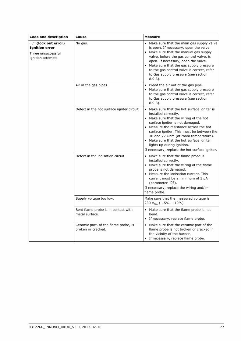
Code and description Cause Measure
F04 (lock out error)Ignition error
Three unsuccessfulignition attempts.
No gas. Make sure that the main gas supply valveis open. If necessary, open the valve.Make sure that the manual gas supplyvalve, before the gas control valve, isopen. If necessary, open the valve.Make sure that the gas supply pressureto the gas control valve is correct, referto Gas supply pressure (see section8.9.3).
•
•
•
Air in the gas pipes. Bleed the air out of the gas pipe.Make sure that the gas supply pressureto the gas control valve is correct, referto Gas supply pressure (see section8.9.3).
••
Defect in the hot surface igniter circuit. Make sure that the hot surface igniter isinstalled correctly.Make sure that the wiring of the hotsurface igniter is not damaged.Measure the resistance across the hotsurface igniter. This must be between the36 and 72 Ohm (at room temperature).Make sure that the hot surface igniterlights up during ignition.
If necessary, replace the hot surface igniter.
•
•
•
•
Defect in the ionisation circuit. Make sure that the flame probe isinstalled correctly.Make sure that the wiring of the flameprobe is not damaged.Measure the ionisation current. Thiscurrent must be a minimum of 3 μA(parameter 109).
If necessary, replace the wiring and/orflame probe.
•
•
•
Supply voltage too low. Make sure that the measured voltage is230 VAC (-15%, +10%).
Bent flame probe is in contact withmetal surface.
Make sure that the flame probe is notbend.If necessary, replace flame probe.
•
•
Ceramic part, of the flame probe, isbroken or cracked.
Make sure that the ceramic part of theflame probe is not broken or cracked inthe vicinity of the burner.If necessary, replace flame probe.
•
•
0312266_INNOVO_UKUK_V3.0, 2017-02-10 77

Code and description Cause Measure
F05 (lock out error)Flame error
Too many flame failuresare detected
Recirculating flue gases due tooincorrect roof or wall flue terminal.
Make sure the flue terminal is installedcorrectly, refer to Venting system (seesection 8.7). If necessary, connect thecorrect flue terminal.Make sure that the terminal is installedcorrectly, refer to Venting system (seesection 8.7). If necessary connect theflue terminal correctly.Make sure that there are no flue gasleaks to the rest of the venting system.Ifnecessary reconnect the venting systemand replace any damaged seals.Make sure that the flue terminaldischarges into a permitted area.Make sure that the CO2-value measuredin the flue gas outlet is correct, refer toCO2 value (see section 8.9.4).Make sure that the CO2 value measuredin the air inlet is below 0.5 vol%.If necessary, reconnect the ventingsystem and change the necessary seals.
•
•
•
•
•
•
•
No sufficient gas supply. Make sure that the gas supply (see section13.3) pressure is correct.
F07 (lock out error)Ionisation error
Ionisation measured afterthe gas control valve wasclosed
Defective gas control valve. Make sure that there is no flame after thegas control valve has closed.If there is a flame, the gas control valvemust be replaced.
•
•
F08 (lock out error)Ionisation error
Ionisation measuredbefore the gas controlvalve was opened
Defective safety relay. Reset the controller.If error appears again, replace thecontroller.
••
F09 (lock out error)Temperature error
Temperature, in the tank is above the97ºC.
See measure of error E01.Make sure that the wiring between 1 and7 of J9 is connected and not damaged.If necessary, replace or reconnect thewiring.When the wiring is reconnected, reset thecontroller.
••
•
•
F11 (blocking error)Ionisation error
Ionisation measured witha closed gas control valve
Defective gas control valve. Make sure that there is no flame after thegas control valve has closed.If there is a flame, the gas control valvemust be replaced.
•
•
F19 (blocking error)Supply voltage error
There is not enough or too much supplyvoltage present, during 60 seconds.The measured voltage must be 230 VAC(-15%, +10%).
Make sure that the supply voltage on thecontroller is correct.If the supply voltage is above or belowthe stated tolerance and the errorpersists, contact your maintenance andservice engineer.
•
•
F21 (lock out error)Air proving switch error
Switch is not closed, whilefan runs during post purge
Damaged wiring/open circuit. See measure of error F03 - Switch is notclosed when fan is running during pre-purge.
78 Installation, Maintenance and Service part

Code and description Cause Measure
S02 (blocking error)Sensor error
Open circuit from sensor 1of the temperature sensor
Sensor is not (correctly) connected. Make sure that the connector isconnected to J3.Make sure that the wire is connected tothe sensor.
•
•
Damaged wiring and/or defectivesensor.
Replace the wiring and/or sensor.
S03 (blocking error)Sensor error
Open circuit from sensor 2of the temperature sensor
Sensor is not (correctly) connected. Make sure that the connector isconnected to J3.Make sure that the wire is connected tothe sensor.
•
•
Damaged wiring and/or defectivesensor.
Replace the wiring and/or sensor.
S12 (blocking error)Sensor error
Short circuit in sensor 1 ofthe temperature sensor
Short circuit in the sensor circuit. Replace the wiring and/or sensor.
S13 (blocking error)Sensor error
Short circuit in sensor 2 ofthe temperature sensor
Short circuit in the sensor circuit. Replace the wiring and/or sensor.
0312266_INNOVO_UKUK_V3.0, 2017-02-10 79

12.1.3 Warnings
NoteFor the coding of the connections, refer to the Electrical wiring diagram (see section13.4).
Indication Cause Remark
Src Service is required The water heater exceeded the pre-setservice interval.
The water heater operates, but displays thiswarning.Periodic maintenance is a part of theWarranty. When you do not obey thiscondition, the warranty will void.
Ano Anode protection isnot working
The water heater runs, but there is noanode protection for the tank.
Proper functioning of the anode protection isa part of the conditions for installation anduse as stated in the Warranty. When you donot obey this condition, the warranty willvoid.
The orange and the green LED of theanode controller are off:
There is no power to the potentiostat.•
Make sure that there is power to thepotentiostat.
The orange LED of the anode controlleris on and the green LED is off:
The cables between the potentiostatand the anode(s) are loose orconnected incorrectly.The earth connection, of theanode(s), is loose.The water heater is not filled withwater.There is short circuit between theanode(s) and the tank.There is low conductivity of thewater.
•
•
•
•
•
Make sure that:The cable between the anode controllerand the anode(s) are connected.If necessary connect the wires correctly.The water heater is filled with water.If necessary, fill the water heater (seesection 8.9.1).The anode is in contact with the tank.If necessary, replace the anode(s).Make sure that the water conductivity iscorrect, refer to Water composition (seesection 8.2.3).
•
•
•
•
The orange and the green LED of theanode controller are on:
The cable between the potentiostatand the display are damaged or notconnected.
•
Make sure that the cable between thepotentiostat and the display is not damagedand connectedIf necessary, replace the wiring or reconnectcable.
n
80 Installation, Maintenance and Service part

13 Appendices
13.1 Technical detailsDescription Unit IR-12-160
IR-20-160IR-12-200IR-20-200
IR-24-245IR-32-245
IR-24-285IR-32-285
IR-32-380
General
Capacity l 160 200 245 285 380
Empty Weight kg 95 106 120 136 155
Maximum floor load kg 255 306 365 421 535
Maximum operating pressure- installation
kPa (bar) 550 (5.5) 550 (5.5) 550 (5.5) 550 (5.5) 550 (5.5)
Maximum operating pressure- tank
kPa (bar) 800 (8) 800 (8) 800 (8) 800 (8) 800 (8)
Control thermostat - adjustment range
°C 40…85 40…85 40…85 40…85 40…85
Control thermostat - defaultvalue
°C 65 65 65 65 65
Hysteresis upwards - adjustment range
°C 2…15 2…15 2…15 2…15 2…15
Hysteresis upwards - defaultvalue
°C 10 10 10 10 10
Number of (electrical) anodes - 1 1 2 2 2
Minimum measured airpressure differential acrossthe pressure switch
Pa ≥ 210 ≥ 210 ≥ 460 ≥ 460 ≥ 460
Setpoint pressure switch Pa 175 175 400 400 400
Heating time ΔT = 45 °C min. 28 (12-160)
18 (20-160)
43 (12-200)
28 (20-200)
26 (24-245)
20 (32-245)
33 (24-285)
25 (32-285)
32
Electrical
Electrical power consumption(peak)
W 85 85 105 105 105
Electrical power consumption(nominal)
W 25 (12-160)
36 (20-160)
25 (12-200)
36 (20-200)
51 (24-245)
85 (32-245)
51 (24-285)
85 (32-285)
85
Supply voltage/Mainfrequency
VAC / Hz 230 (-15%, +10%) / 50 (± 1)
IP-class - IP20
0312266_INNOVO_UKUK_V3.0, 2017-02-10 81

13.2 DimensionsSize Description Unit IR-12-160
IR-20-160IR-12-200IR-20-200
IR-24-245IR-32-245
IR-24-285IR-32-285
IR-32-380
Dimensions water heater
A Height (1) mm 1270 1545 1545 1745 1745
D Width mm 560 560 610 610 675
E Depth mm 780 780 830 830 890
G Flue gas outlet/Air inlet mm/mm 80/125 80/125 80/125 80/125 80/125
Dimensions connections
1 Cold water supplyconnection (female)
- Rp 3/4 Rp 3/4 Rp 1 Rp 1 Rp 1
2 Hot water outletconnection (female)
- Rp 3/4 Rp 3/4 Rp 1 Rp 1 Rp 1
3 Gas control valveconnection (male)
mm 15 15 15 15 15
4 Drain valve connection(female)
- Rp 3/4 Rp 3/4 Rp 3/4 Rp 3/4 Rp 3/4
5 T&P-valve connection(female)
- Rp 3/4 Rp 3/4 Rp 1 Rp 1 Rp 1
6 Cleaning/inspectionopening
mm 95x70 95x70 95x70 95x70 95x70
7 Condensation drainageconnection (female)
mm Ø 40 Ø 40 Ø 40 Ø 40 Ø 40
14 Circulation connection(female)
- Rp 3/4 Rp 3/4 Rp 3/4 Rp 3/4 Rp 3/4
1 - This is the minimal height. When the adjustable legs under the water heater are fully extended, the height is20 mm higher.
82 Installation, Maintenance and Service part

0312266_INNOVO_UKUK_V3.0, 2017-02-10 83

13.3 Gas detailsDescription Unit IR-12-160
IR-12-200IR-20-160IR-20-200
IR-24-245IR-24-285
IR-32-245IR-32-285IR-32-380
Gas category 2H (G20)
Diameter of the venturirestrictor
mm 3.95 3.95 3.95 3.95
Nominal Load (gross) kW 12.1 20.0 24.4 32.2
Nominal output kW 11.7 (12-160)11.9 (12-200)
19.1 23.5 (24-245)23.8 (24-285)
30.7 (32-245)31.0 (32-285)31.3 (32-380)
Supply pressure mbar 20.0 20.0 20.0 20.0
CO2 (full load) vol% 9.3 ± 1.0 9.3 ± 1.0 9.3 ± 1.0 9.3 ± 1.0
O2 (full load) vol% 4.3 ± 1.8 4.3 ± 1.8 4.3 ± 1.8 4.3 ± 1.8
Gas consumption (1) m3/h 1.2 1.9 2.3 3.1
NOx-emission mg/kWh GCV 22 30 33 37
Mass flow rate flue gases(minimal load)
kg/h 9.1 9.1 9.1 9.1
Mass flow rate flue gases(nominal load)
kg/h 19.0 31.4 38.4 50.7
Flue gas temperature(nominal load)
ºC 42 61 57 65
Gas category 3P (G31)
Diameter of the venturirestrictor
mm 3.05 3.05 3.05 3.05
Nominal Load (gross) kW 11.8 19.6 23.9 31.5
Nominal output kW 11.4 (12-160)11.6 (12-200)
18.7 23.0 (24-245)23.3 (24-285)
30.1 (32-245)30.4 (32-285)30.7 (32-380)
Supply pressure mbar 37.0…50.0 37.0…50.0 37.0…50.0 37.0…50.0
CO2 (full load) vol% 10.0 ± 1.0 10.0 ± 1.0 10.0 ± 1.0 10.0 ± 1.0
O2 (full load) vol% 5.7 ± 1.5 5.7 ± 1.5 5.7 ± 1.5 5.7 ± 1.5
Gas consumption kg/h 0.8 1.4 1.7 2.3
NOx-emission mg/kWh GCV 23 30 33 37
Mass flow rate flue gases(minimal load)
kg/h 8.8 8.8 8.8 8.8
Mass flow rate flue gases(nominal load)
kg/h 20.0 33.1 40.5 53.3
Flue gas temperature(nominal load)
ºC 39 56 55 59
1 - Based on 1013.25 mbar and 15°C.
84 Installation, Maintenance and Service part

13.3.1 Energy labeling
Description Unit IR-12-160 IR-12-200 IR-20-160 IR-20-200
Declared load profile
Load profile - XL XL XL XL
Energy efficiency class( Energy label)
- A A A A
Energy efficiency % 92 94 92 91
Daily electricity consumption kWh 0.175 0.181 0.172 0.182
Daily fuel consumption kWh GCV 20.526 19.924 20.661 20.853
Mixed water 40 °C (V40) l 272 372 772 1111
Additional load profile
Load profile - - - - XXL
Energy efficiency class(Energy label)
- - - - A
Energy efficiency % - - - 90
Daily electricity consumption kWh - - - 0.191
Daily fuel consumption kWh GCV - - - 26.761
Mixed water 40 °C (V40) l - - - 382
Description Unit IR-24-245 IR-24-285 IR-32-245 IR-32-285 IR-32-380
Declared load profile
Load profile - XXL XXL XXL XXL XXL
Energy efficiency class( Energy label)
- A A A A A
Energy efficiency % 92 91 92 90 90
Daily electricity consumption kWh 0.192 0.207 0.201 0.219 0.204
Daily fuel consumption kWh GCV 26.210 26.414 26.255 26.638 26.748
Mixed water 40 °C (V40) l 599 682 1976 2282 3372
Additional load profile
Load profile - - - - - 3XL
Energy efficiency class(Energy label)
- - - - - -
Energy efficiency % - - - - 92
Daily electricity consumption kWh - - - - 0.256
Daily fuel consumption kWh GCV - - - - 50.428
Mixed water 40 °C (V40) l - - - - 548
0312266_INNOVO_UKUK_V3.0, 2017-02-10 85
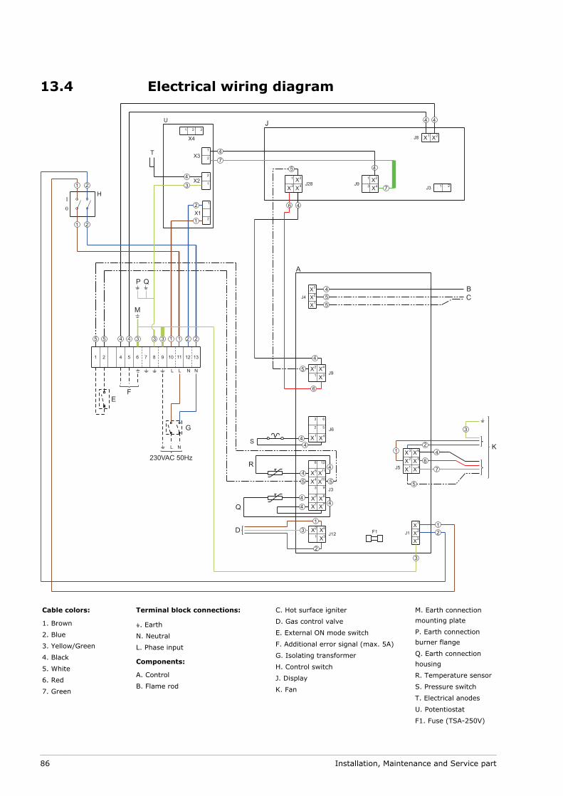
13.4 Electrical wiring diagram
Cable colors:
1. Brown
2. Blue
3. Yellow/Green
4. Black
5. White
6. Red
7. Green
Terminal block connections:
A. Earth
N. Neutral
L. Phase input
Components:
A. Control
B. Flame rod
C. Hot surface igniter
D. Gas control valve
E. External ON mode switch
F. Additional error signal (max. 5A)
G. Isolating transformer
H. Control switch
J. Display
K. Fan
M. Earth connectionmounting plate
P. Earth connectionburner flange
Q. Earth connectionhousing
R. Temperature sensor
S. Pressure switch
T. Electrical anodes
U. Potentiostat
F1. Fuse (TSA-250V)
86 Installation, Maintenance and Service part
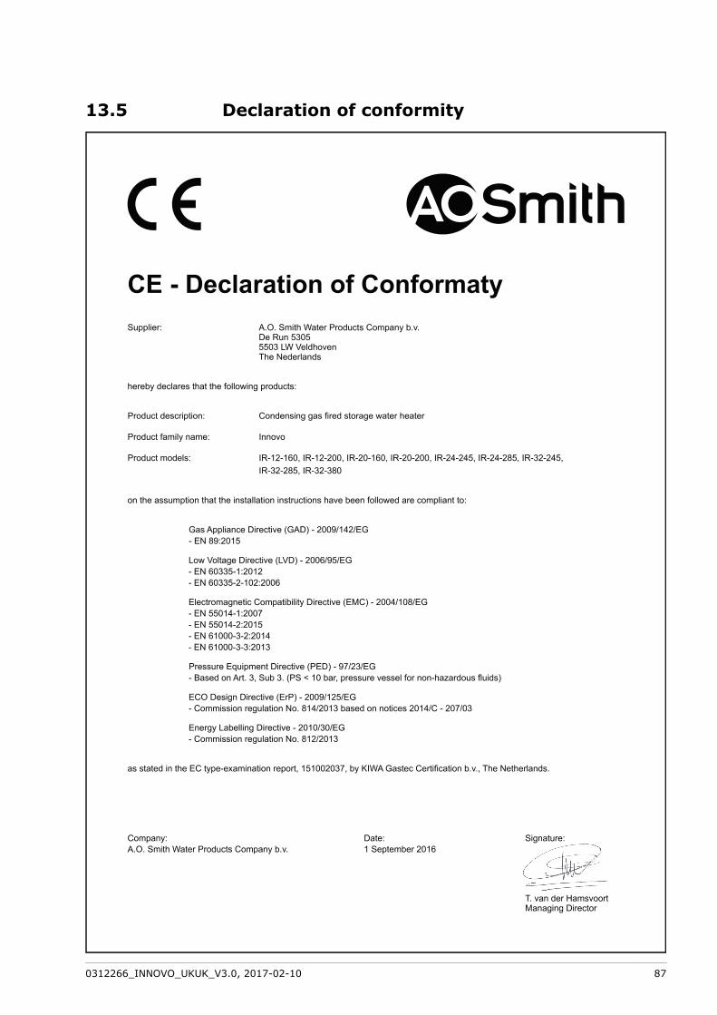
13.5 Declaration of conformity
0312266_INNOVO_UKUK_V3.0, 2017-02-10 87
13.6 WarrantyTo register your water heater, you can complete and return the enclosed warranty card.You can also register your water heater on-line through the A.O. Smith website.
Article 1: General warrantyIf, after verification and at the sole discretion of A.O. Smith, a component or part (withexclusion of the glass lined steel tank) of a water heater supplied by A.O. Smith proveswithin two years of the original installation date to be defective or fails to functioncorrectly due to manufacturing and/or material defects, then A.O. Smith shall repair orreplace this component or part.
Article 2: Tank warrantyIf, after inspection and at the sole discretion of A.O. Smith, the glass-lined steel tank of awater heater supplied by A.O. Smith proves within 3 years of the original installation dateto be leaking due to rust or corrosion occurring on the water side, then A.O. Smith shalloffer to replace the defective water heater with an entirely new water heater of equivalentsize and quality. The warranty period given on the replacement water heater shall beequal to the remaining warranty period of the original water heater that was supplied.Notwithstanding that stated earlier in this article, in the event that unfiltered or softenedwater is used, or allowed to stand in the water heater, the warranty shall be reduced toone year from the original installation date.
Article 3: Conditions for Installation and UseThe warranty set out in Articles 1 and 2 will apply solely under the following conditions:
The water heater is installed under strict adherence to A.O. Smith installationinstructions for the specific model, and the relevant government and local authorityinstallation and building codes, rules and regulations in force at the time ofinstallation.The water heater remains installed at the original site of installation.The water heater is used exclusively with drinking water, which at all times canfreely circulate (a separately installed heat exchanger is mandatory for heating salinewater or corrosive water).The tank is safeguarded against harmful scaling and lime build-up by means ofperiodic maintenance.The water temperatures in the heater do not exceed the maximum setting of thethermostats, which form a part of the water heater.The water pressure and/or heat load do not exceed the maximum values stated onthe water heater rating plate.The water heater is installed in a non-corrosive atmosphere or environment.The water heater is connected to a protected cold water supply arrangement, whichis approved by the relevant authority; with sufficient capacity for this purpose;supplying a water pressure not greater than the working pressure stated on thewater heater; and where applicable by a likewise approved temperature andpressure relief valve; fitted in accordance with installation instructions of A.O. Smithapplying to the specific model of water heater, and further in compliance with thegovernment and local authority installation and building codes, rules and regulations.The water heater is at all times fitted with cathodic protection. If sacrificial anodesare used for this, these must be replaced and renewed when, and as soon as, theyare 60% or more consumed. When power anodes are used, it is important to ensurethat they continue to work properly.
•
••
•
•
•
••
•
88 Installation, Maintenance and Service part
Article 4: ExclusionsThe warranty set out in Articles 1 and 2 will not apply in the event of:
damage to the water heater caused by an external factor;misuse, neglect (including frost damage), modification, incorrect and/or unauthoriseduse of the water heater and any attempt to repair leaks;contaminants or other substances having been allowed to enter the tank;the conductivity of the water being less than 125 μS/cm and/or the hardness(alkaline earth ions) of the water being less than 1.00 mmol/litre;unfiltered, recirculated water flowing through or being stored in the water heater;any attempts at repair to a defective water heater other than by an approved serviceengineer.
Article 5: Scope of the warrantyThe obligations of A.O. Smith by virtue of the warranty provided do not extend beyonddelivery free of charge from the warehouse of the parts or components or water heater tobe replaced; transport, labour, installation and other costs associated with thereplacement shall not be borne by A.O. Smith.
Article 6: ClaimsA claim on grounds of the specified warranty must be submitted to the dealer from whomthe water heater was purchased, or to another authorised dealer for A.O. Smith WaterProducts Company products. Inspection of the water heater as referred to in Articles 1 and2 shall take place in one of the laboratories of A.O. Smith Water Products Company.
Article 7: Obligations of A.O. SmithA.O. Smith grants no other warranty or guarantee over its water heaters nor the(assemblies or parts of) water heaters supplied for replacement, other than the warrantyexpressly set out in these Articles.
Under the terms of the supplied warranty, A.O. Smith is not liable for damage to personsor property caused by (assemblies or parts, or the glass-lined steel tank of) a(replacement) water heater that it has supplied.
••
••
••
0312266_INNOVO_UKUK_V3.0, 2017-02-10 89

90 Installation, Maintenance and Service part
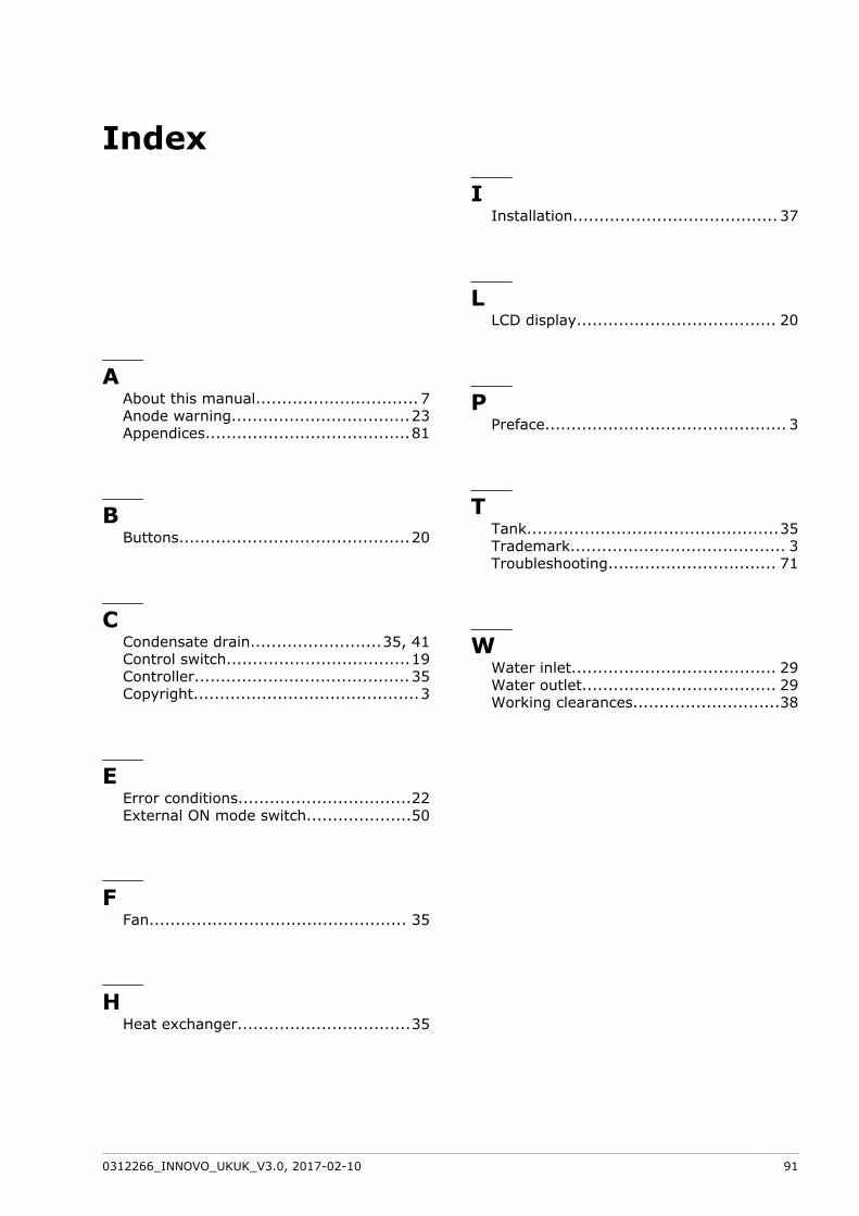
Index
AAbout this manual............................... 7Anode warning..................................23Appendices.......................................81
BButtons............................................20
CCondensate drain.........................35, 41Control switch...................................19Controller.........................................35Copyright...........................................3
EError conditions.................................22External ON mode switch....................50
FFan................................................. 35
HHeat exchanger.................................35
IInstallation....................................... 37
LLCD display...................................... 20
PPreface.............................................. 3
TTank................................................35Trademark......................................... 3Troubleshooting................................ 71
WWater inlet....................................... 29Water outlet..................................... 29Working clearances............................38
0312266_INNOVO_UKUK_V3.0, 2017-02-10 91

92 Installation, Maintenance and Service part