AO concepts for extremely large telescopes Rich Dekany Jet Propulsion Laboratory...
54
-
Upload
rosamond-blake -
Category
Documents
-
view
220 -
download
2
Transcript of AO concepts for extremely large telescopes Rich Dekany Jet Propulsion Laboratory...

Today’s show...
• Extremely Large Telescopes– Historical perspective
– CELT concept
• Adaptive optics observation modes– Seeing limited
– Single conjugate
– Multiconjugate
– Extreme
• CELT configuration options

Lessons of History
• Plot of largest optical/IR telescope size vs. time reveals exponential growth– Remarkable given various
social, economic, and technical factors
• Extrapolating from Keck 10 m:• 10 m 1993
• 25 m 2034
• 50 m 2065
• 100 m 2097
– History does not explain how future gains will be made
Log10 collectin
g area (meters2
)
Courtesy J. Nelson

Large telescope projects
1950-2020
Hale
Keck1
Keck2MMTHETGemini (x2)VLT (x4)Magellan….others
LBT (x2)GTC
CELT
HST
SIRTF
NGST
1949
1990
1995
2000
2005
2010
2015
2020

California Extremely Large Telescope (CELT)
• Features– 30 meter class optical / IR
observatory
– Filled-aperture, fully pointable
– Advanced adaptive optics
– State-of-the-art instrument complement
– Cost ~ TBD
– Completion date ~ TBD
• Baseline design– Two-mirror Ritchey-Chretien
– F/1.5 primary mirror• ~1080 hexagonal segments
• 0.9 m (shortest edge) segment diameter
• Segments organized onto rafts for handling
• Non-interlocking edge sensors
– Final F/# ~ 15 (may shorten)
– Nasmyth foci only

CELT Science
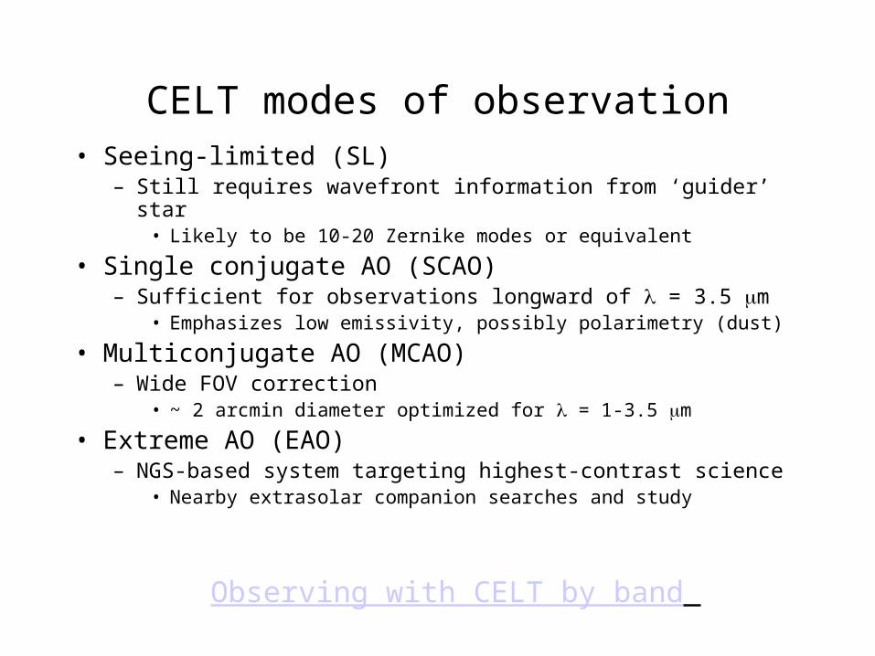
CELT modes of observation• Seeing-limited (SL)
– Still requires wavefront information from ‘guider’ star• Likely to be 10-20 Zernike modes or equivalent
• Single conjugate AO (SCAO)– Sufficient for observations longward of = 3.5 m
• Emphasizes low emissivity, possibly polarimetry (dust)
• Multiconjugate AO (MCAO)– Wide FOV correction
• ~ 2 arcmin diameter optimized for = 1-3.5 m
• Extreme AO (EAO)– NGS-based system targeting highest-contrast science
• Nearby extrasolar companion searches and study
Observing with CELT by band


• High SNR, high imaging, and spectral resolution– Accretion environments
– Study disks to centrifugal radius (Rc) ~ 10 AU at distances up to 1 kpc
– R ~ 105 to obtain velocities to 3 km/s to estimate mass accretion rate
– Measure infall rate as function of position and angular momentum
– Cepheids out to redshift z ~ 0.1 – Measure H0 and omega matter
– Age determination of giants (measure t0)– Measure age of stars via thorium decay in giants below RGB tip
– Requires R ~ 3 x 10⁵ and S/N ~ 1000.
– Geometry of the Universe via SNe at z ~ 3 (measure q0)– Break degeneracy of omega matter and omega lamba
– Spectroscopy of z = 0.5 - 5 galaxies– Measure kinematics and chemistry
– Planetary science• KBO searches
• ~ 20 km resolution imaging of Jupiter’s atmosphere– Comparable to Galileo images
– Many others…

Courtesy M. Mountain

CELT Telescope

Scaling laws• Cost
• Recent history: Cost ~ D2.3
– Extrapolating Keck costs = 30 m cost ~$1.2B– Need innovation to get break this ‘law’
• Define the scale size of interest as S• Deflections due to self-weight, ~ S2
– Deflection due to fixed load/m2, such as thin segments, ~ S1
• Angular change due to self-weight ~ /L ~ S1
– Angular change due to fixed load/m2 ~ S0
• Mass ~ S3 (extremely fast, so often ignored, use m ~ S3/2)» Keck moving mass: 250 tons» GBT (100m radio dish) mass: 8000 tons (law predicts 250,000 tons)
– Stiffness of structure, k ~ F/ ~ mG/ ~ S3/2/S2 ~ S-1/2
– Resonant frequency ~ -1/2 ~ S-1
• Wind loading– Excitation frequency characteristic of eddy size ~ vwind/S ~ S-1
» Same scaling as the structure resonance frequency
– Deflections due to wind ~ F/k ~ S2/S-1/2 ~ S5/2

Large telescope
cost scaling laws
0.2
0.4
0.6
0.8
1.0
1.2
1.4
1.6
1.8
2.0
2.2
0 1.0 2.0
log TELESCOPE DIAMETER (m)
SCALING LAW DATA
OPTICAL ENDOSTRUCTURESRADIOOPTICAL
HET
HALESUB
KECK
VLT
NTT
MMT-1
GEM(COL)
(MAG)MMT-2
RA
DIO
BONN
DSN
log
TE
LE
SC
OP
E C
OS
T(M
$,1
99
9$
)
SMT
EXO
STRUCTU
RES
NANJING
100 M$
ENDOSTRUCTURE TELESCOPES
4 10 20 100
2.4
30
TELESCOPE DIAMETER (m)

Recent large telescope costs
• Item Keck1($Y88) Keck2($Y95) HET
Dome development 6.7 8.6 1.2
Drive and control system 2.8 2.1 1.3
Mirror support system 15.2 4.1 (optics)
Observatory development 9.8 10.3 2.4
Project managementand engineering 7.7 8.1 1.1
SSC/support 1.7 0.4 0.2?
Support Facilities 5.6 6.5 0.0?
Telescope structure 9.2 10.8 1.2
Operations Testing 0.0 5.5 2.0
Total 93.7 77.7 16.5

CELT Primary Mirror

CELT primary mirror
Fun Fact! Approximately the same as ocular collecting area
of the population of the City of Los Angeles
• Baseline– Segment thickness ~ 45 mm
• Keck segment thickness is 75 mm
– Non-locking capacitive edge sensors• Keck sensors interlock
– Segments grouped into rafts
• Equivalent collecting area to all major existing observatories combined

CELT Keck

Optimal Segment Size (Nelson, Chanan)
Factors favoring many small segments:
• Lower mass, easier to support
• Lower material costs
• Easier to fabricate:
Factors favoring fewer large segments:
• Smaller error propagation (sensors actuators/wavefront)surface = 0.74 (Nseg)1/2 sensor
4.4 for Nseg = 36
15. for Nseg = 1098
• Easier to phaseno. edges Nseg =
3
22
22 k
RaC
84 for Nseg = 363168 for Nseg = 1098
C22 = astigmatic coefficienta = hexagon side lengthR = off axis distancek = primary radius of curvature

Keck Stressed Mirror Polishing Set-up
Optical Polishing Table
Back Support
Polishing Lap
WeightsBlank
Bending Levers

title
force devices (12)
Arrows indicate force direction and magnitude required to create / remove astigmatism
polished surface
blank
posts glued to blank edge
Proposed CELT Stressed Mirror Polishing Set-up

Mirror Segment 7.5 cm
Sensor Paddle
Sensor BodySensor Mount
Conducting Surfaces
2 mm
L
R = 35 m
Keck Sensor Geometry

titleProposed CELT Sensor Geometry
Non-Interlocking Sensors
CELT Adaptive Optics

CELT modes of observation• Seeing-limited (SL)
– Still requires wavefront information from ‘guider’ star• Likely to be 10-20 Zernike modes or equivalent
• Single conjugate AO (SCAO)– Sufficient for observations longward of = 3.5 m
• Emphasizes low emissivity, possibly polarimetry (dust)
• Multiconjugate AO (MCAO)– Wide FOV correction
• ~ 2 arcmin diameter optimized for = 1-3.5 m
• Extreme AO (EAO)– NGS-based system targeting highest-contrast science
• Nearby extrasolar companion searches and study
Observing with CELT by band

Optical design issues for CELT AO
• NGS SL mode– Minimize number of surfaces
• NGS SCAO– Maintain large science field of view
– Minimize emissivity
• LGS MCAO– Provide for multiple conjugation locations
– Get relatively large field through a complex relay
– LGS elongation
– LGS fratercide
– Requires multiple NGS, as well
• NGS EAO– Minimize scattered light (high spatial frequency errors)

Seeing-limited (SL) observing mode
• Even SL mode requires ‘aggressive’ active optics– Primary focus mode
– Primary sensor error propagation
– Wind-induced vibrations in structure
• Regular telescope ‘guider’ replaced with low-order wavefront sensor

Nact & Sky coverage vs. wavlength(D=30m, 20 e- per subap)
10
100
1000
10000
100000
0.1 1 10
Wavelength (microns)
0.001
0.01
0.1
1
10
Nact for const fitting Strehl 0.8
Nact for const fitting Strehl 0.5
Nact for const fitting Strehl 0.2
P(N>0) in isoplanatic patch
Isoplanatic Angle (asec)

Single conjugate (SCAO) observing mode
• Natural guide star system– Full sky coverage
• Based upon relatively loose wavefront error budget, which allows for large subaperture wavefront sensing and large isoplanatic angle
– Diffraction limited at ~ 3.5 m or longer• Requires ~ 500-1000 actuators
• Single adaptive element – potentially an adaptive secondary– Would prefer to minimize emmissivity, but resolution is the major
science driver (NGST wins in sensitivity)
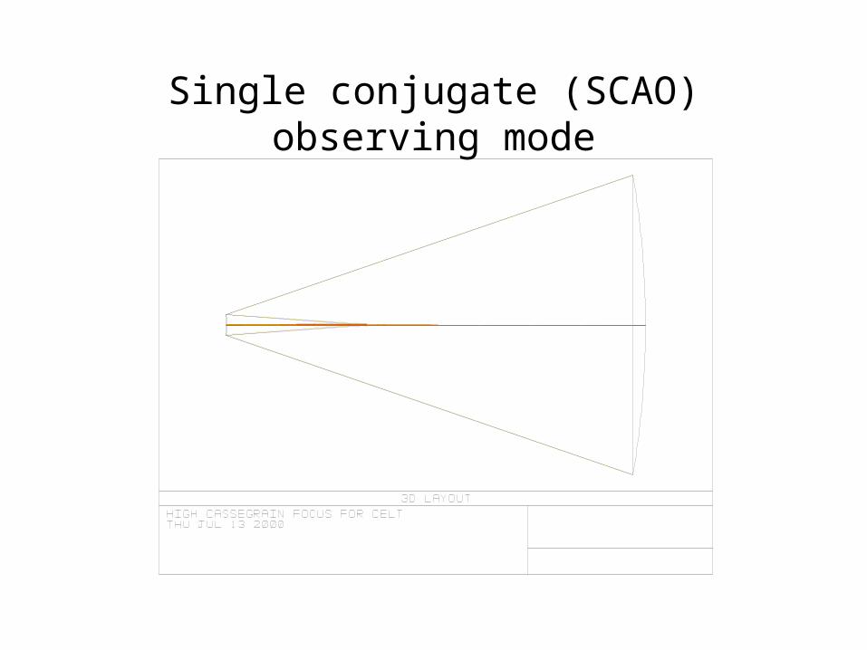
Single conjugate (SCAO) observing mode

SCAO issues
• Even for single-conjugate AO, many hard problems exist– Segmented primary mirror
• Segment vibrations• ACS error propagation of low order primary mirror modes
– Need more information than usual from ‘guider’ camera (now a wavefront sensor)
– Deformable mirrors• Adaptive secondary mirrors may be desirable
– Minimizes emissivity for IR observations– Requires technology development
• Number of actuators, size, stroke, linearity, hysteresis, coatings,…
– Control• Incorporation of NGS data into control laws• Computation cost
– Very large number of actuators require new algorithms
– Systematics• Small diffraction width accentuates previously acceptable error

Multiconjugate (MCAO) observing mode
• Natural guides stars do not provide sufficient sky coverage at near-IR wavelengths (1-2.5 m)– Artificial beacons are necessary (ref. Ed Kibblewhite’s talk from
Thursday)– Focal anisoplanatism (‘cone error’)
• MS wavefront error ~ (D/d0)5/3
where d0 is linear function of beacon height and scales ~ 6/5• Mauna Kea model atmosphere
– d0, assuming 45 degree zenith angle, » d0(10 km, MK, 45 zen) = 1.08m » d0(92 km, MK, 45 zen) = 3.60m
which leads to, for 1 mm observing wavelength, D = 30 m,
FA(10km) = 2540 nm
FA(92km) = 931 nm which are both obviously unacceptable wavefront errors.

MCAO issues I
• Need multiple laser guide stars– Due to focal anisoplanatism– Required even for ‘narrow field’ AO (i.e. single isoplanatic angle)
• All guide stars would like to operate in ‘closed loop’ (i.e. enjoy AO correction)
• How much useful information, in any, is available from open-loop guide star information?
• Need multiple natural guide stars– Tilt indeterminism of individual beacons leads to unsensed modes
of turbulence• Major contribution from focus and astigmatic atmospheric modes• Ellerbroek: 3 NGS are sufficient for 5 LGS
– Research area: How does one exploit whatever wavefront information supplied by fortuitous NGS’s

MCAO issues II
• Laser beacon elongation– Sodium layer has finite thickness (typ. ~10 km)
• For Shack-Hartmann sensor, each subaperture sees elongated beacon
• Beam elongation ~ (beacon length * off-axis distance)/(height2)
– Possible solutions?• Gating of wavefront sensor camera (natural for Rayleigh beacons)
• Membrane mirror for adaptive focus during pulse flight
• Elongated beacons still give good centroid estimates in one direction– Is there really a problem?
• Laser beacon fratercide– Multiple laser beacons tend to obscure each other with the Rayleigh
scatter tail• Worst effect for subapertures near beacon launch points
• Beacon launch from behind secondary always a problem

MCAO issues III
• Many reflections– Renewed emphasis on coatings
• Minimize emissivity and scattering
• Requires new calibration techniques– Multiple wavefront sensors much each now be calibrated
• Above and beyond problem of lower acceptable rms wavefront error
• Complex software– Multiple guide star acquisition

Three MCAO geometries
• Offner relay
• Compact triad
• Crossed MCAO

Offner Relay
• 1:1 relay• Three concentric spherical surfaces• Corrected field is determined by physical size of relay
– In other words, the corrected field (in mm) of a 2 meter Offner is twice the dimension of a 1 meter Offner
• Located beyond Nasmyth focus of an ELT, first two reflections of Offner occur at interesting conjugates– Example:
• ELT secondary is first ‘conjugate’• First two reflections of Offner conjugate to 2 km and 8 km altitude
• Requires large, powered adaptive elements– Exploit adaptive secondary technologies?

CELT AO - 2amin Offner relayConjugates at “0”km, 2km, 8km

CELT - MCAO Offner relay (detail)

CELT - MCAO Double Offner relay(Conjugates at “0”, 2, 5, 8, 12 km)

Pupil magnification
• Internal CELT pupils are limited by FOV– Practical angles at any (current) adaptive device about 20 degrees
incidence
– For isoplanatic angle of 20 asec, limit of pupil magnification ~ 1/3600
• 8.33 mm pupil diameter
• Actuator spacing of 130 m for 30m telescope (for 4,000 Nact system)
– Selecting standard pupil diameter of 100 mm• 20 asec FOV becomes < 2 degrees
• 1mm AO technology is initially usable (Nact ~ 8,000)
• 200 m MEMs development increases Nact to ~ 200,000
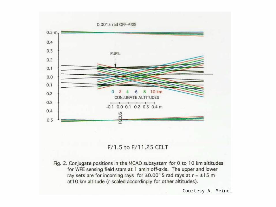
Courtesy A. Meinel

Courtesy A. Meinel

Courtesy A. Meinel

Extreme (EAO) observing mode
• Visible, high contrast observations– Requires 10,000 – 100,000 phase actuators– Will likely require amplitude correction– Requires very high photon fluxes for sufficient SNR per
subaperture• Laser power required scales as -18/5
– Hard– Return to NGS only system, at least initially
» Used for nearby stars only
– Limitations to exosolar planet detection may be imposed by primary mirror
• Diffraction from segment gaps• Segment vibrations

No-laser atmospheric tomography (Raggozoni, Gilmozzi)
• Large aperture telescopes sample an enormous volume of the Earth’s atmosphere
• Multiple NGS’s could be used to determine 3-D structure of turbulence
• Multiple (perhaps fewer) DMs could correct a significant field– For example, for 30m CELT, beam shear of 15m (arbitrary), yields 5
arcmin radius
• Requires N guide stars– However, corrected field grows as D2
• Finding 3 NGS’s of 13th mag within 5 arcmin (30m CELT) reasonable (P ~ 50%)
• Finding 5 within 8.5 amin (50m CELT) likely (P ~ 90%)
– Exploit all useful NGS’s within technical field with multiple pyramids in Foucault-like wavefront sensor (ref. Gary Chanan’s talk from Monday)

CELT Structure

CELT – K structural schematic
Courtesy S. Medwadowski

CELT – MWD(millimetre dish)
Concept
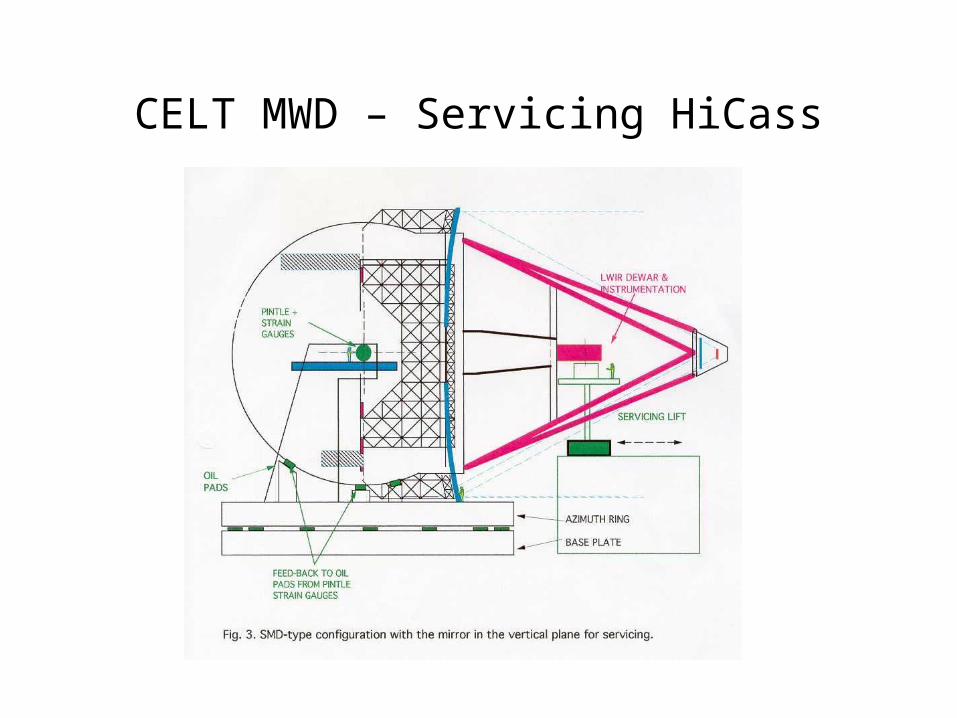
CELT MWD – Servicing HiCass

CELT MWD concept
Concept by A. Meinel, D. Woody, and R. DekanyModel by A. Meinel

CELT MWD - Inboard Nasymth

CELT MWD - Outboard Nasmyth

CELT MWD - Servicing Secondaries

ELT AO Technology Roadmap