AnyBus-M Profibus DPV Fieldbus Appendix - RESolu...
102
HMS Industrial Networks AB Germany Japan Sweden U.S.A UK +49- 721 - 96472 - 0 +81- 45 - 478 -5340 +46- 35 - 17 29 20 +1- 773 - 404 - 3486 +44- 1908 - 359301 [email protected] [email protected] [email protected] [email protected] [email protected] Fieldbus Appendix Anybus-M Profibus DPV1 Rev. 1.20
Transcript of AnyBus-M Profibus DPV Fieldbus Appendix - RESolu...

HMS Industrial Networks AB
GermanyJapanSwedenU.S.AUK
+49- 721 - 96472 - 0+81- 45 - 478 -5340+46- 35 - 17 29 20+1- 773 - 404 - 3486+44- 1908 - 359301
[email protected]@[email protected]@[email protected]
Fieldbus AppendixAnybus-M Profibus DPV1
Rev. 1.20


Preface About This Document
How To Use This Document ............................................................................................................ P-1
Important User Information .............................................................................................................. P-1
Related Documentation ...................................................................................................................... P-1
Revision List.......................................................................................................................................... P-1
Conventions Used in This Document .............................................................................................. P-2
Support .................................................................................................................................................. P-2
Chapter 1 About the Anybus-M Profibus DPV1
Features...................................................................................................................................................1-1
Fieldbus Conformance Notes .............................................................................................................1-1
Overview ................................................................................................................................................1-2Connectors ....................................................................................................................................1-2Indicators ......................................................................................................................................1-3
Chapter 2 Implementation Details
Initialisation............................................................................................................................................2-1
Maximum I/O Sizes .............................................................................................................................2-1
Supported Profibus Services................................................................................................................2-2
Class 2-Only Mode................................................................................................................................2-2
Memory Map..........................................................................................................................................2-3
‘Input’ and ‘output’ Definitions ..........................................................................................................2-4
Chapter 3 Database Management
Database download procedure............................................................................................................3-2
Master Record Data Structure.............................................................................................................3-3Bus Parameter Data Block ...........................................................................................................3-3Master User Data Block ..............................................................................................................3-5
Slave Record Data Structure................................................................................................................3-6General Data Block .....................................................................................................................3-6Parameter Data Block ..................................................................................................................3-7Configuration Data Block.............................................................................................................3-7Address Table Block ....................................................................................................................3-8Slave User Data Block .................................................................................................................3-8Extended User Parameter Data Block .........................................................................................3-8
DPRAM Address Assignment Modes ...............................................................................................3-9Simple Mode Example ...............................................................................................................3-10Complex Mode Example ............................................................................................................3-10Addressing Mode & Storage Format ..........................................................................................3-11
Table of Contents
Table of Contents

Table of Contents II
Chapter 4 Fieldbus Specific Mailbox Commands
Overview ................................................................................................................................................4-1
General....................................................................................................................................................4-2Fieldbus Specific Initialisation (FB_INIT)...................................................................................4-2Set Operating Mode (FB_APPL_SET_OPERATION_MODE)..........................................4-5Shift Operating Mode Request (FB_ABM_SHIFT_OPERATION_MODE_REQ)............4-7Set Slave Mode (FB_APPL_SET_SLAVE_MODE) ...........................................................4-9Get Slave Diagnostics (FB_APPL_GET_SLAVE_DIAG) ................................................4-12Get Slave Configuration (FB_APPL_GET_SLAVE_CONFIG) .......................................4-14Set Slave Address (FB_APPL_SET_SLAVE_ADDRESS)..............................................4-16Get Master Diag (FB_APPL_GET_MASTER_DIAG) ....................................................4-18Get Live List (FB_APPL_GET_LIVE_LIST) ...................................................................4-20
Database Management .......................................................................................................................4-21Start Database Download (FB_APPL_START_DATABASE_DOWNLOAD) ............4-21End Database Download (FB_APPL_END_DATABASE_DOWNLOAD) .................4-22Master Record Download (FB_APPL_MASTER_RECORD_DOWNLOAD)................4-23Master Record Upload (FB_APPL_MASTER_RECORD_UPLOAD) ............................4-25Slave Record Download (FB_APPL_SLAVE_RECORD_DOWNLOAD) .....................4-26Slave Record Upload (FB_APPL_SLAVE_RECORD_UPLOAD)..................................4-28Delete Database (FB_APPL_DELETE_DATABASE) ....................................................4-30Get Database Info (FB_APPL_GET_DATABASE_INFO) .............................................4-31Download New Database Request (FB_ABM_DOWNLOAD_NEW_DB_REQ) ...........4-33
Acyclic Communication, Class 1.......................................................................................................4-34Class 1 Read (FB_APPL_MSAC1_READ) ........................................................................4-34Class 1 Write (FB_APPL_MSAC1_WRITE)......................................................................4-36PROFIdrive V3 Acyclic Parameter Access (FB_APPL_MSAC1_PROFIDRIVE_V3_PARAM_WRITE) .....................................4-38
Acyclic Communication, Class 2.......................................................................................................4-41Class 2 Connection Initiate (FB_APPL_MSAC2_INITIATE) ............................................4-41Class 2 Connection Abort (FB_APPL_MSAC2_ABORT)...................................................4-46Class 2 Connection Abort Indication (FB_APPL_MSAC2_ABORT_IND)........................4-48Class 2 Read (FB_APPL_MSAC2_READ) ........................................................................4-50Class 2 Write (FB_APPL_MSAC2_WRITE)......................................................................4-52Class 2 Data Transport (FB_APPL_MSAC2_DATA_TRANSPORT) ...........................4-54Class 2 Connection Status (FB_APPL_MSAC2_CNXN_STATUS) .................................4-56
DPV1 Alarm Handling.......................................................................................................................4-59Alarm Indication (FB_ABM_MSAL1_ALARM_IND) .....................................................4-59Alarm Confirmation (FB_ABM_MSAL1_ALARM_CON)...............................................4-61
Chapter 5 Fieldbus Specific Area
General....................................................................................................................................................5-1
Overview ................................................................................................................................................5-1
Registers..................................................................................................................................................5-2Slave Configured List (E40h...E4Fh) ..........................................................................................5-2Data Transfer List (E50h...E5Fh) .............................................................................................5-2Slave Diagnostic List (E60h...E6Fh) ..........................................................................................5-2Master Status Field (E70h...E72h) .............................................................................................5-3Master Init Field (E77h...E7Ch) ................................................................................................5-3Class 2 Connection Live-List (E80h...E8Fh) ..............................................................................5-3
Table of Contents III
Chapter 6 Control Register Area
General....................................................................................................................................................6-1
Registers..................................................................................................................................................6-1Module Status Register (FE2h...FE3h) .......................................................................................6-1Changed Data Field (FECh...FEBh) ..........................................................................................6-1Event Cause (FECh...FEDh) .....................................................................................................6-2Event Notification (FEEh...FEFh).............................................................................................6-2Watchdog Counter IN (FD2h...FD3h)........................................................................................6-2
Appendix A DP Error Codes
Appendix B DPV1 Error Codes
Class 1-Related Errors ......................................................................................................................... B-1
Class 2-Related Errors ......................................................................................................................... B-2
Appendix C Message Error Codes (END_INIT)
Appendix D Connectors
Application Connector ........................................................................................................................D-1
Fieldbus Interface.................................................................................................................................D-1
Serial Interface ......................................................................................................................................D-1
Appendix E Mechanical Specification
Measurements, PCB.............................................................................................................................E-1
Appendix F Electrical Characteristics
Power Supply ........................................................................................................................................ F-1
Protective Earth (PE) Requirements................................................................................................. F-1
Appendix G Environmental Specification
Temperature..........................................................................................................................................G-1
Relative Humidity.................................................................................................................................G-1
EMC compliance..................................................................................................................................G-1

Preface
About This Document
How To Use This Document
This document is intended to be used as a supplement to the Anybus-S Parallel Design Guide. The read-er of this document is expected to have basic knowledge in the Profibus fieldbus system, and commu-nication systems in general. Please consult the general Anybus-S Parallel Design Guide for general information about the Anybus-S platform.
Important User Information
The data and illustrations found in this document are not binding. We, HMS Industrial Networks AB, reserve the right to modify our products in line with our policy of continuous product development. The information in this document is subject to change without notice and should not be considered as a com-mitment by HMS Industrial Networks AB. HMS Industrial Networks AB assumes no responsibility for any errors that may appear in this document.
There are many applications of this product. Those responsible for the use of this device must ensure that all the necessary steps have been taken to verify that the application meets all performance and safe-ty requirements including any applicable laws, regulations, codes, and standards.
Anybus® is a registered trademark of HMS Industrial Networks AB. All other trademarks are the prop-erty of their respective holders.
Related Documentation
Revision List
Document name AuthorAnybus-S Parallel Design Guide HMS Industrial Networks ABPROFIdrive - Profile Drive Technology (ver. 3) PNOProfibus Specification EN50170 PNOExtensions to EN50170 (DPV1) PNODigital Communications IEC61158 Type 3 (Profibus) IEC
Rev. Date Author Chapter(s) Description<=1.05 - - - (see previous revisions)1.06 2005-01-25 ToT 3 Corrected ‘TSET‘ parameter range.1.10 2005-02-01 PeP All Misc minor corrections1.20 2005-06-07 PeP -
-4455AB
Merged chapters ‘Memory Map’ & ‘Initialisation’ >‘Implementation Details’Moved appendix ‘Supported Profibus Services’ > ‘Implementation Details’Added commands (‘Acyclic Communication, Class 2’).Updated ‘FB_INIT’ & added ‘FB_APPL_GET_MASTER_DIAG’Added section ‘Master Init Field (E77h...E7Ch)’Added section ‘Class 2 Connection Live-List (E80h...E8Fh)’Updated list of supported Profibus services. Added section ‘Class 2-Related Errors’

About This Document P-2
Conventions Used in This Document
The following conventions are used throughout this manual:
• Numbered lists provide sequential steps• Bulleted lists provide information, not procedural steps• The term ‘module’ is used when referring to the Anybus module• The term ‘application’ is used when referring to the device connected to the Anybus application
connector• Hexadecimal values are written in the format NNNNh, where NNNN is the hexadecimal value.• Commands instructs the module to perform certain task• Functions are commands that returns data
Support
HMS Sweden (Head Office)E-mail: [email protected]: +46 (0) 35 - 17 29 20Fax: +46 (0) 35 - 17 29 09Online: www.anybus.com
HMS AmericaE-mail: [email protected]: +1-773-404-2271Toll Free: 888-8-AnybusFax: +1-773-404-1797Online: www.anybus.com
HMS GermanyE-mail: [email protected]: +49-721-96472-0Fax: +49-721-964-7210Online: www.anybus.com
HMS JapanE-mail: [email protected]: +81-45-478-5340Fax: +81-45-476-0315Online: www.anybus.com

Chapter 1
About the Anybus-M Profibus DPV1The Anybus-M Profibus DPV1 communication module provides complete Profibus-DPV0/DPV1 master functionality via the patented Anybus-S application interface. The hardware is optimized for high throughput and can be used in mono- or multi-master networks up to 12 Mbit/s.
The module can be configured either externally using a PC-based Profibus configuration tool such as Anybus NetTool for Profibus, or internally via the application interface.
This product conforms to all aspects of the parallel Anybus-S application interface defined in the Any-bus-S/M Parallel Design Guide, making it fully interchangeable with any other device following that specification.
Features
• Up to 125 slaves can be connected
• Up to 2048 bytes input & output data
• 2kbyte or 4kbyte DPRAM modes
• Extended Mode allowing up to 1536 bytes of I/O to reside in DPRAM
• Up to 12 Mbit/s on Profibus
• RS-485 optically isolated Profibus interface with on-board DC/DC converter.
• Configuration via application interface or via PC configuration tool
• Acyclic Communication (DPV1, Class 1 & 2)
• Alarm Handling (DPV1)
Fieldbus Conformance Notes
This product is pre-certified for network compliance. While this is done to ensure that the final product can be certified, it does not necessarily mean that the final product doesn’t need recertification. Contact HMS for further information.

About the Anybus-M Profibus DPV1 1-2
Overview
Connectors
Application Interface
The application interface features a standard Anybus-S 2kbyte parallel DPRAM interface. It is however also possible to use 4kbyte DPRAM by utilizing pin 34 as address pin 11 (A11). For more information, see Appendix D-1 “Application Connector”.
For further information about the Anybus-S application interface, please consult the general Anybus-M Design Guide.
Profibus Interface
The connector features a galvanically isolated Profibus interface. The standard connector is a 9 pin fe-male DSUB, however other connector designs are also possible. For more information about supported connector types and pin assignments, see Appendix D-1 “Fieldbus Interface”.
Note: It is required to use connectors with integrated termination resistors if the module is connected to the end of a bus segment.
Configuration Interface
This is an RS232 compatible serial interface, intended to be used with PC based configuration tools such as Anybus NetTool for Profibus.
Several connector types are supported, the standard connector is a 9 pin male DSUB connector. For more information about supported connector types and pin assignments, see Appendix D-1 “Connec-tors”
# Description1 Application Interface2 Profibus Interface3 Configuration Interface4 Master Status Indicators5 Anybus Watchdog LED (Consult the general Anybus-S Parallel Design Guide for further information)
2 3
4
5
1

About the Anybus-M Profibus DPV1 1-3
Indicators
Master Status Indicators
These leds indicate run time status and errors to the user.
Led State Description1 - Master Status Green Operate mode
Green, flashing Clear modeRed Stop modeOff Offline
2 - Database Status Green Database OKGreen, flashing Database download in progressRed Database invalidOff No database downloaded
3 - Communication Status Green Data exchange with all configured slavesGreen, flashing Data exchange with at least one configured slaveRed Bus control error (possible bus short circuit or configuration error)Off No data exchange with any of the configured slaves
4 - Token Hold Green The module has the tokenOff The module does not have the token
All Red Fatal error
1 2
4 3

Chapter 2
Implementation Details
Initialisation
At power on/reset, the module will wait for an initialisation sequence consisting of mailbox messages. This process determines basic operational parameters such as the memory layout etc.
Basically, the initialisation sequence looks as follows:
Power On (Reset)
1. Send ‘Start Init’1
This step starts the initialisation sequence.
2. Send ‘FB Init’ (Optional)
‘FB Init’ is used to initialise some of the more ad-vanced functions of the module, such as the Ex-tended DPRAM mode. If only basic master functionality is required, this step can be omit-ted.For more information about this message, see 4-2 “Fieldbus Specific Initialisation (FB_INIT)”.
3. Send ‘Anybus Init’1
‘Anybus Init’ is used to set up the I/O sizes and various configuration bits.
4. Send ‘End Init’1
This step ends the initialisation sequence.
Ready
(For more information regarding the initialisation process, consult the Anybus-S Parallel Design Guide)
Maximum I/O Sizes
The maximum I/O sizes for the ‘Anybus Init’ mailbox message in the different modes are listed below:
Note: ‘I/O length’ must equal ‘Total length’ since parameter data is not supported.
1. For more information about this mailbox message, consult the general Anybus-S Parallel Design Guide.
‘Anybus Init’ Parameter Standard Mode Extended ModeI/O length 2048 2048DPRAM length 512 1536Total length 2048 2048

Implementation Details 2-2
Supported Profibus Services
The following table lists all service available according to the Profibus specification.
- Service supportedNS - Service not supported
Class 2-Only Mode
The module can operate either as a combined Class 1 and 2 master, or as a Class 2-only master. The latter imposes the following restrictions:
• The module cannot communicate with any slaves that might be present in the database (Slave Record). However, it will communicate with other masters (token passing etc.). Therefore, in or-der for this mode to work, it is required that the database contains at least a valid Master Record.
• Mailbox commands intended for Class 1 operations will be rejected by the module.
(See also 2-1 “Initialisation” and 4-2 “Fieldbus Specific Initialisation (FB_INIT)”).
Service Profibus VersionMaster Class 1 Master Class 2
Request Response Request ResponseDDLM_Data-Exchange DPV0 - NS -DDLM_Set_Prm DPV0 - NS -DDLM_Chk_Cfg DPV0 - NS -DDLM_Slave_Diag DPV0 - -DDLM_Global_Control DPV0 - NS -DDLM_Get_Cfg DPV0 - - -DDLM_Set_Slave_Add DPV0 - - -DDLM_Read_Input DPV0 - - NS -DDLM_Read_Output DPV0 - - NS -DDLM_Get_Master_Diag DPV0 - -DDLM_Start_Seq DPV0 - NS NS -DDLM_Download DPV0 - NS NS -DDLM_Upload DPV0 - NS NS -DDLM_End_Seq DPV0 - NS NS -DDLM_Act_Param_Brct DPV0 - NS NS -DDLM_Act_Param DPV0 - NS NS -MSAC1_Read DPV1 - - -MSAC1_Write DPV1 - - -MSAL1_Alarm DPV1 - - -MSAL1_Alarm_Ack DPV1 - - -MSAC2_Initiate DPV1 - - -MSAC2_Read DPV1 - - -MSAC2_Write DPV1 - - -MSAC2_DataTransport DPV1 - - -MSAC2_Abort DPV1 - - -Data_eXchange_Broadcast DPV2 NS - - -Isochrone_mode (Takt sync) DPV2 NS - - -Extended_Set_Prm (Subscriber) DPV2 NS - - -

Implementation Details 2-3
Memory Map
The DPRAM in the Anybus-M DPV has been extended to allow fast access to larger amounts of cyclical fieldbus data. This is accomplished by using pin 34 of the application connector as address line 11 (A11), giving an effective address range of 4kbyte instead of the standard 2kbyte. The advantage of this is that while the total I/O size remains limited to 2kbyte, a larger portion of this I/O data can be accessed di-rectly in the dual port memory instead of via the mailbox interface.
Note that this feature is optional; e.g. if A11/pin 34 is not implemented, the memory layout is consistent with the standard Anybus-S memory map.
Extended Mode (4kbyte DPRAM)
Standard Mode (2kbyte DPRAM)
Note: The addresses in the 2kbyte map above have an offset of 800h when compared to the 2kbyte memory map found in the Anybus-S/M Design Guide. If an Anybus-S/M module with a 2kbyte mem-ory model is used in an application designed for a 4kbyte memory model, or if the Anybus-M DPV is used in its 2kbyte mode in a 4kbyte memory model application, the application system software must take this offset into account when accessing the DPRAM (e.g. the 4kbyte model address A00h equals the 2kbyte model address 200h when the module does not use the A11 address pin).
Address: Area: Access: Description:
000h - 5FFh Input Area(1536 bytes) R/W
The structure of these areas is deter-mined by the contents of the database. See 3-9 “DPRAM Address Assignment Modes” for more information.
600h - BFFh Output Area(1536 bytes) RO
C00h - D1Fh Mailbox In R/W See Anybus-S Parallel Design Guide
D20h - E3Fh Mailbox Out RO - “ -
E40h - FBFh Fieldbus Specific Area RO See 5-1 “Fieldbus Specific Area”
FC0h - FFDh Control Registers R/W See 6-1 “Control Register Area”FFEh - FFFh Handshake Registers R/W See Anybus-S Parallel Design Guide
Address: Area: Access: Description:
800h - 9FFh Input Area(512 bytes) R/W The structure of these areas is deter-
mined by the contents of the database. See 3-9 “DPRAM Address Assignment Modes” for more information.A00h - BFFh Output Area
(512 bytes) RO
C00h - D1Fh Mailbox In R/W See Anybus-S Parallel Design Guide
D20h - E3Fh Mailbox Out RO - “ -
E40h - FBFh Fieldbus Specific Area RO See 5-1 “Fieldbus Specific Area”
FC0h - FFDh Control Registers R/W See 6-1 “Control Register Area”FFEh - FFFh Handshake Registers R/W See Anybus-S Parallel Design Guide

Implementation Details 2-4
‘Input’ and ‘output’ Definitions
When using the Anybus-M DPV master module together with the bus configuration software NetTool-PB it should be noted that different definitions for ‘input data’ and ‘output data’ are used:
• The conventions in this manual and in the Anybus-M DPV follows the same convention as is used for other Anybus-S/Anybus-M modules; The term ‘input data’ refers to data written to the network while the term ‘output data’ refers to data received from the network, regardless of if the module is a master or a slave.
• NetTool-PB uses the same definition as an end user normally will see from a configuration tool. The term ‘input data’ refers to data read from a slave device while the term ‘output data’ refers to data written to a slave device.
At first the contradiction in these two definitions may appear as a problem but since the end users does not need to be aware of the definitions used between the Anybus-M DPV module and the application system, only the definition in the NetTool-BP will apply to them.

Chapter 3
Database ManagementThe module needs a bus database in order to know which slaves to establish connections to, how they shall be configured and how much data to exchange with them. In most cases the NetTool-BP config-uration software from HMS will be used for this but it is also possible to use a third-party configurator and load the database into the module via the mailbox interface.
Note: This chapter is not intended to give technical background or technical details of the different da-tabase parameters or their usage. For questions concerning the Profibus system itself, the official Profi-bus specification documents should be considered the main source of information.

Database Management 3-2
Database download procedure
If the database is supposed to be downloaded using mailbox messages the figure below illustrates the download procedure. For more information about these mailbox messages, see 4-21 “Database Man-agement”.
FB_APPL_START_DATABASE_DOWNLOAD
request
FB_APPL_START_DATABASE_DOWNLOAD
response
FB_APPL_END_DATABASE_DOWNLOAD
request/response
FB_APPL_MASTER_RECORD_DOWNLOAD
request/response
FB_APPL_SLAVE_RECORD_DOWNLOAD
request/response
Module sends
FB_ABM_DOWNLOAD_NEW_DB_REQYes
Yes
Download more
slaves?Yes
No
Application responds to
FB_ABM_DOWNLOAD_NEW_DB_REQ
FB_INIT
"Special functions"
bit 2=1
No
Module status register
bit 4 = 1 (RDR) in
AB_INIT
No
Module is
automatically re-
started
Module sets the RDR
bit in the Module
status register
Application must reset
the ABM-DPV
FB_APPL_DELETE_DATABASE
request/response

Database Management 3-3
Master Record Data Structure
The master record data block is made up of two structures:
• Bus Parameter Data Block• Master User Data Block
Bus Parameter Data Block
This field contains parameter that are necessary for the overall bus communication.
Parameters written in italic are related to DPV1.
Byte Offset Designation Type / [range] Contents
0-1 Bus_Para_Len UINT16 / [96]Length of the entire Bus parameter block (i.e Bus_Para +Master_User_Data) including Bus_Para_Len
2 TS UINT8 / [0-125] Address of this station.
3 Data rate UINT8 / [0-11]
11 = 45.45 kbit/s10 = (Reserved)9 = 12000 kbit/s8 = 6000 kbit/s7 = 3000 kbit/s6 = 1500 kbit/s5 = Reserved4 = 500 kbit/s3 = 187.5 kbit/s2 = 93.75 kbit/s1 = 19.2 kbit/s0 = 9.6 kbit/s
4-5 TSL
UINT16/[maxTSDR+15 to 16383]
Slot time. Max time the master will wait for a response from the addressed slave.Timebase: Tbit
6-7 minTSDR
UINT16/[11 to MIN(255, maxTSDR –1, 34 + 2* TSET + TQUI) ]
Minimum Station Delay time Responder.This is the minimum waiting time for a slave until it is allowed to send the response frame to the mas-ter. minTSDR in the Prm_Data for the slaves are based on this parameter. Timebase: Tbit
8-9 maxTSDR
UINT16/[35 + 2* TSET + TQUI to 1023]
Maximum Station Delay time Responder. The addressed slave must respond within this time.Timebase: Tbit
10 TQUI
UINT8/[0-MIN(31, minT-SDR –1) ]
Quiet time. Time required for a transmitting node to switch from send to receive.Timebase: Tbit
11 TSET UINT8 / [1 to 255]
Setup time. Time elapsing in the node between a data frame being received and a response occur-ring.Timebase: Tbit
12-15 TTRUINT32/[256 to 16776960]a
Target rotation time. This is the maximum time available for token rotation. The difference between the actual token rotation time (TRR) deter-mines how much time the master still has to send data frames to its slaves.Timebase: Tbit
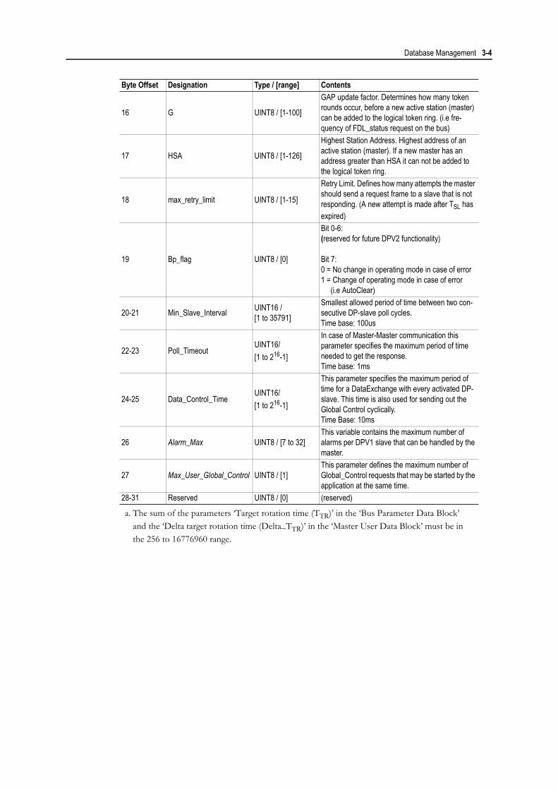
Database Management 3-4
16 G UINT8 / [1-100]
GAP update factor. Determines how many token rounds occur, before a new active station (master) can be added to the logical token ring. (i.e fre-quency of FDL_status request on the bus)
17 HSA UINT8 / [1-126]
Highest Station Address. Highest address of an active station (master). If a new master has an address greater than HSA it can not be added to the logical token ring.
18 max_retry_limit UINT8 / [1-15]
Retry Limit. Defines how many attempts the master should send a request frame to a slave that is not responding. (A new attempt is made after TSL has expired)
19 Bp_flag UINT8 / [0]
Bit 0-6:(reserved for future DPV2 functionality)
Bit 7:0 = No change in operating mode in case of error1 = Change of operating mode in case of error (i.e AutoClear)
20-21 Min_Slave_Interval UINT16 /[1 to 35791]
Smallest allowed period of time between two con-secutive DP-slave poll cycles.Time base: 100us
22-23 Poll_TimeoutUINT16/[1 to 216-1]
In case of Master-Master communication this parameter specifies the maximum period of time needed to get the response.Time base: 1ms
24-25 Data_Control_TimeUINT16/[1 to 216-1]
This parameter specifies the maximum period of time for a DataExchange with every activated DP-slave. This time is also used for sending out the Global Control cyclically.Time Base: 10ms
26 Alarm_Max UINT8 / [7 to 32]This variable contains the maximum number of alarms per DPV1 slave that can be handled by the master.
27 Max_User_Global_Control UINT8 / [1]This parameter defines the maximum number of Global_Control requests that may be started by the application at the same time.
28-31 Reserved UINT8 / [0] (reserved)
a. The sum of the parameters ‘Target rotation time (TTR)’ in the ‘Bus Parameter Data Block’ and the ‘Delta target rotation time (Delta_TTR)’ in the ‘Master User Data Block’ must be in the 256 to 16776960 range.
Byte Offset Designation Type / [range] Contents

Database Management 3-5
Master User Data Block
This field contains data that is unique for the Anybus-M Profibus DPV1 implementation.
Byte Offset Designation Type / [range] Contents
0-1 Master_User_Data_Len UINT16 / [64] Length of the Master_User_Data including Master_User_Data_Len
2-33 Master_Class2_Name Visible String / [32] Indicates the name of the DP-master (class 2) which provided the values for parameter set.
34-35 Tid1 UINT16/[37 to 1023] Master idle time 1 (Tid1=35 + 2* TSET + TQUI) Timebase: Tbit
36-37 Tid2 UINT16/[37 to 1023]Master idle time 2 (Tid2 = maxTSDR)Timebase: Tbit
38-39 Reserved UINT16 / [0] (reserved)
40-43 Delta_TTRUINT32/[0 to 16776704]a
a. The sum of the parameters ‘Target rotation time (TTR)’ in the ‘Bus Parameter Data Block’ and the ‘Delta target rotation time (Delta_TTR)’ in the ‘Master User Data Block’ must be in the 256 to 16776960 range.
Delta target rotation time.If there are other masters on the bus, the total tar-get rotation time for these masters should be entered here.Timebase: Tbit
44-47 Reserved UINT32 / [0] (reserved)
48-49 Repeater UINT16 1: Repeater on bus0: No repeater
50 Group_Sync UINT8
Bit 0-7 corresponds to group 1-8.Example:If group 5 and 1 are “sync groups” and group 6, 2 and 1 are “freeze groups”, then Group_Sync = 0x11 and Group_Freeze = 0x23.
51 Group_Freeze UINT852 Ident Number high UINT8 Master ident-number assigned by PNO53 Ident Number low UINT8
54 Addressing mode UINT80: Byte addressing.1: Word addressing.(See 3-11 “Addressing Mode & Storage Format”)
55 Storage format UINT80: Motorola (Big Endian)1: Intel (Little Endian)(See 3-11 “Addressing Mode & Storage Format”)
56-59 TCT UINT32 / [0] (reserved for future DPV2 functionality. Set to 0)60 max TSH UINT8 / [0] (reserved for future DPV2 functionality. Set to 0)61-63 Reserved UINT8 (reserved)

Database Management 3-6
Slave Record Data Structure
The slave record data is made up of the following data blocks:
• General Data Block• Parameter Data Block (Prm_Data)• Configuration Data Block (Cfg_Data)• Address Table Block (Add_Tab)• Slave User Data Block (Slave_User_Data)• Extended User Parameter Data Block (Ext_User_Prm_Data)
General Data Block
Parameters written in italic are related to DPV1.
Byte Offset Designation Type / [range] Contents
0-1 Slave_Para_Len UINT16/[44 to 1749] Length of the entire “Slave parameter record” (in bytes) including the “Slave_Para_Len”.
2 Sl_flag UINT8
Flag that describes the properties of the slave.Bit 7: ActiveBit 6: New_Prm Bit 5: Fail_SafeBit 4: (reserved)Bit 3: DPV1_SupportedBit 2: DPV1_Data_Types Bit 1: Extra_Alarm_SAP Bit 0: (reserved)
3 Slave_Type UINT8 / [0, 16-255] 0: DP-slave1-15: (reserved)16-255: Manufacturer specific
4 Max_Diag_Data_Len UINT8 / [6-244] Max diagnostic data length that the slave supports. 5 Reserved UINT8/ [0] Reserved
6 Max_Channel_Data_Len UINT8/[4-244]
Maximum size of the MSAC1-PDU (4 byte header + data) for the DPV1 slave.
7 Diag_Upd_DelayUINT8/[0-15 (extendible to 255) ]
This parameter is used to count the number of DDLM_Slave_Diag.con in state DIAG2 while Diag_Data. Prm_Req is still set (for slaves with reduced performance)
8 Alarm_Mode UINT8 / [0-7]
This parameter specifies the maximum number of possible active alarms.0 = 1 alarm of each type1 = 2 alarms in total2 = 4 alarms in total3 = 8 alarms in total4 = 12 alarms in total5 = 16 alarms in total6 = 24 alarms in total7 = 32 alarms in total
9 Add_Sl_Flag UINT8 / [0x00-0x03] Bit 0 NA_To_AbortBit 1 Ignore_AclrBit 2-7 (reserved)
10-11 MSAC1_Timeout UINT16 / [1 to 216-1]Specifies the maximum time it may take for a DPV1-slave to respond to a DPV1 request.Time Base: 10ms
12-15 Reserved UINT8 / [0] (reserved)
Database Management 3-7
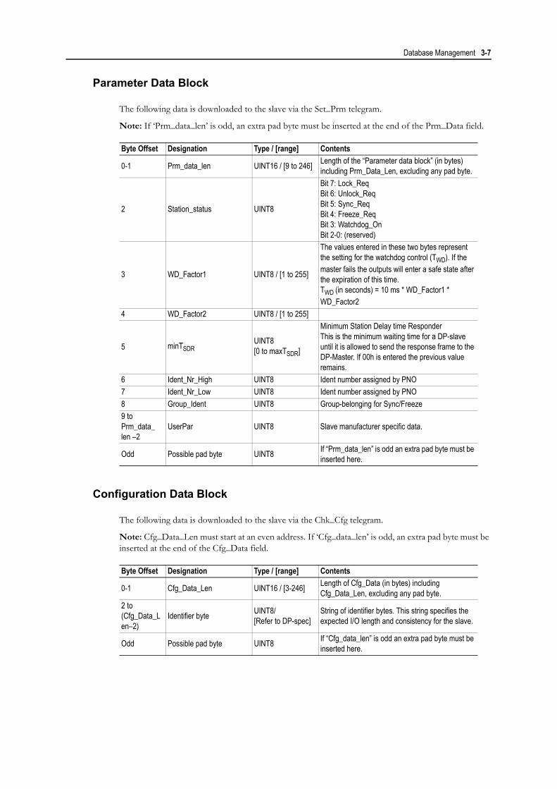
Parameter Data Block
The following data is downloaded to the slave via the Set_Prm telegram.
Note: If ‘Prm_data_len’ is odd, an extra pad byte must be inserted at the end of the Prm_Data field.
Configuration Data Block
The following data is downloaded to the slave via the Chk_Cfg telegram.
Note: Cfg_Data_Len must start at an even address. If ‘Cfg_data_len’ is odd, an extra pad byte must be inserted at the end of the Cfg_Data field.
Byte Offset Designation Type / [range] Contents
0-1 Prm_data_len UINT16 / [9 to 246] Length of the “Parameter data block” (in bytes) including Prm_Data_Len, excluding any pad byte.
2 Station_status UINT8
Bit 7: Lock_ReqBit 6: Unlock_ReqBit 5: Sync_ReqBit 4: Freeze_ReqBit 3: Watchdog_OnBit 2-0: (reserved)
3 WD_Factor1 UINT8 / [1 to 255]
The values entered in these two bytes represent the setting for the watchdog control (TWD). If the master fails the outputs will enter a safe state after the expiration of this time.TWD (in seconds) = 10 ms * WD_Factor1 * WD_Factor2
4 WD_Factor2 UINT8 / [1 to 255]
5 minTSDRUINT8[0 to maxTSDR]
Minimum Station Delay time ResponderThis is the minimum waiting time for a DP-slave until it is allowed to send the response frame to the DP-Master. If 00h is entered the previous value remains.
6 Ident_Nr_High UINT8 Ident number assigned by PNO7 Ident_Nr_Low UINT8 Ident number assigned by PNO8 Group_Ident UINT8 Group-belonging for Sync/Freeze9 to Prm_data_len –2
UserPar UINT8 Slave manufacturer specific data.
Odd Possible pad byte UINT8 If “Prm_data_len” is odd an extra pad byte must be inserted here.
Byte Offset Designation Type / [range] Contents
0-1 Cfg_Data_Len UINT16 / [3-246] Length of Cfg_Data (in bytes) including Cfg_Data_Len, excluding any pad byte.
2 to (Cfg_Data_Len–2)
Identifier byte UINT8/[Refer to DP-spec]
String of identifier bytes. This string specifies the expected I/O length and consistency for the slave.
Odd Possible pad byte UINT8 If “Cfg_data_len” is odd an extra pad byte must be inserted here.

Database Management 3-8
Address Table Block
This structure describes how process data should be mapped in the DPRAM. See 3-9 “DPRAM Address Assignment Modes” for detailed information about address assignment.
Note: The first parameter (Add_Tab_Len) must start at an even address!
Slave User Data Block
This field contains manufacturer specific data that characterize the slave for the master.
Extended User Parameter Data Block
In DPV2 a new Profibus telegram has been added to make it possible to download the ‘subscription table’ to a DPV2 slave that operates in subscriber-mode. The following data will be downloaded to the DPV2 master via this telegram.
Byte Offset Designation Type / [range] Contents
0-1 Add_Tab_Len UINT16 / [6 to 980] Length of the entire Address Table including Add_Tab_Len.
2 Add_Tab_In_Len UINT8 / [0 to 244]
Number of input offset entries in the Add_Tab_In_Offset table.If Add_Tab_In_Len = 1 the process input area is considered to be contiguous, and the first (and only) word in Add_Tab_In_Offset is assumed to be the start offset of this contiguous area.
3 Add_Tab_Out_Len UINT8 / [0 to 244]
Number of output offset entries in the Add_Tab_Out_Offset table.If Add_Tab_Out_Len = 1 the process output area is considered to be contiguous, and the first (and only) word in Add_Tab_Out_Offset is assumed to be the start offset of this contiguous area.
4 - … Add_Tab_In_Offset[Add_Tab_In_Len] UINT16 / [1 to 244]
This field determines the offset addresses of the input-data and indicates the offset in number of words (if word addressing is used) or number of bytes (if byte addressing is used).
… Add_Tab_Out_Offset [Add_Tab_Out_Len] UINT16 / [1 to 244]
This field determines the offset addresses of the output-data and indicates the offset in number of words (if word addressing is used) or in number of bytes (if byte addressing is used).
Byte Offset Designation Type / [range] Contents
0-1 Slave_User_Data_Len UINT16 / [6] Length of the Slave_User_Data including Slave_User_Data_Len (Always 6 bytes)
2 OutputDataLen UINT8 / [0-244] Length of the used output data (in bytes).3 InputDataLen UINT8 / [0-244] Length of the used output data (in bytes).4-5 UINT8 / [0] (reserved, set to zero.)
Byte Offset Designation Type / [range] Contents
0-1 Ext_User_Prm_Data_Len UINT8 / [2 to 246] Length of the Ext_User_Prm_Data including Ext_User_Prm_Data_Len.
2 to (Ext_User_Prm_Data_Len–1)
Ext_User_Prm_Data UINT8 (reserved for future DPV2 functionality)

Database Management 3-9
DPRAM Address Assignment Modes
There are two different ways of assigning process data to the DPRAM, simple mode and complex mode. Which mode to use is defined in the Address Table, that is part of the slave record in the database.
A slave will be operated in complex mode if Add_Tab_In_Len or Add_Tab_Out_Len is greater than one, otherwise simple mode (see table below)
• Simple Mode
In this mode all process data that belongs to a slave is located in a contiguous block. In other words, the data blocks, associated with each Identifier byte in the Cfg_Data, will be located after each other without gaps. Two offset-entries in the Address Table points out where the process in-/out data begins.Simple addressing mode results in a smaller Address Table, which in turn gives a smaller database compared to complex addressing mode.
• Complex Mode
In this mode the data blocks that are associated with each Identifier byte in the Cfg_Data can be located anywhere in the process data area. This means that gaps in the process data for one slave is allowed.One entry in the Cfg_Data results in one entry in the Address Table, except for Identifier bytes with no data. If one entry in Cfg_Data specifies both in- and output there will be two entries in Add_Tab (one for in and one for out).
It is possible to mix simple- and complex addressing mode, i.e. one slave can work in complex mode while another slave works in simple mode. It is even possible that a slaves input data is treated in a com-plex mode while its output data is treated in simple mode, and vice versa.
Add_Tab_xxx_Len = 0 Add_Tab_xxx_Len = 1 Add_Tab_xxx_Len = 2..244
Add_Tab_In_Len: (Slave has no input data) Inputs are copied according to Simple Addressing mode.
Inputs are copied according to Complex Addressing mode
Add_Tab_Out_Len: (Slave has no output data)Outputs are copied accord-ing to Simple Addressing mode.
Outputs are copied accord-ing to Complex Addressing mode

Database Management 3-10
Simple Mode Example
The slave in the example has 6 words input- and 10 words output data described by 4 Identifier bytes.
Complex Mode Example
(Same slave as in previous example using complex mode.)
Offset: DPRAM In area CfgData0000h Config_Data_Len=06h0040h Identifier 1 = 4 words Identifier 1=F3h (4 words in + 4 words out consistency over total length)
Identifier 2 = 2 words Identifier 2=D1h (2 words in, consistency over total length)
Identifier 3=60h (1 word out, consistency over unit)
Identifier 4=E4h (5 words out, consistency over total length)
AddTabAdd_Tab_Len=08h
Offset: DPRAM Out area Add_Tab_In_Len=01h0000h Add_Tab_Out_Len=01h0060h Identifier 1 = 4 words Add_Tab_In_Offset=40h
Identifier 3 = 1 word Add_Tab_Out_Offset=60hIdentifier 4 = 5 words
Offset: DPRAM In area CfgData0000h Config_Data_Len=06h0040h Identifier 1 = 4 words Identifier 1=F3h (4 words in + 4 words out consistency over total length)
Identifier 2=D1h (2 words in, consistency over total length)
00C0h Identifier 2 = 2 words Identifier 3=60h (1 word out, consistency over unit)
Identifier 4=E4h (5 words out, consistency over total length)
AddTabAdd_Tab_Len=0Eh
Offset: DPRAM Out area Add_Tab_In_Len=02h0000h Add_Tab_Out_Len=03h0060h Identifier 1 = 4 words Add_Tab_In_Offset=40h
Add_Tab_In_Offset=C0h0084h Identifier 4 = 5 words Add_Tab_Out_Offset=60h
Add_Tab_Out_Offset=160h0160h Identifier 3 = 1 word Add_Tab_Out_Offset=084h

Database Management 3-11
Addressing Mode & Storage Format
The addressing mode determines starting point of the modules in the I/O area of the DPRAM. The addressing mode is specified in the Master User Data Block, see 3-5 “Master User Data Block”.
• Byte addressing:
The I/O area is byte oriented. Modules may start at any byte address (odd or even). The offsets in the Address table is in number of bytes.
• Word addressing:
The I/O area is word oriented. Modules must start at even byte addresses. The offsets in the Ad-dress table is in number of words.
Example:
Abbreviations:
OB0 - Output Byte 0IB0 - Input Byte 0OW1 - Output Word 1IW1 - Input Word 1etc.
Offset in DPRAMByte Addressing Mode Word Addressing Mode
Byte Modules Word Modules Byte Modules Word ModulesByte 0 OB0/IB0
OW0/IW0OB0/IB0
OW0/IW0Byte 1 OB1/IB1 -Byte 2 OB2/IB2
OW1/IW1OB1/IB1
OW1/IW1Byte 3 OB3/IB3 -Byte 4 OB4/IB4
OW2/IW2OB2/IB2
OW2/IW2Byte 5 OB5/IB5 -

Database Management 3-12
Storage format determines the byte representation in the DPRAM for a word module. The storage for-mat is specified in the Master User Data Block, see 3-5 “Master User Data Block”.
• Motorola format (Big endian):
High byte – Low byteThis is the normal byte representation on a Profibus Network.
• Intel format (Little endian):
Low byte – High byteNote: Using Intel format will slightly decrease performance of the module since the module will have to swap the bytes internally due to the Motorola format used on the Profibus network.
Example:
Offset in DPRAM Motorola Format Intel FormatByte 0 OW0/IW0 (High byte) OW0/IW0 (Low byte)Byte 1 OW0/IW0 (Low byte) OW0/IW0 (High byte)Byte 2 OW1/IW1 (High byte) OW1/IW1 (Low byte)Byte 3 OW1/IW1 (Low byte) OW1/IW1 (High byte)Byte 4 OW2/IW2 (High byte) OW2/IW2 (Low byte)Byte 5 OW2/IW2 (Low byte) OW2/IW2 (High byte)

Chapter 4
Fieldbus Specific Mailbox CommandsThis chapter describes the fieldbus specific mailbox commands in the module. Consult the Anybus-S Parallel Design Guide for more information regarding mailbox functionality.
Overview
Application-initiated Messages
Anybus-initiated Messages
The following messages may be issued spontaneously by the module:
Command Message Allowed in ‘Class 2-Only’ Mode Page01h FB_INIT Yes 4-202h FB_APPL_SET_OPERATION_MODE No 4-503h FB_APPL_SET_SLAVE_MODE No 4-904h FB_APPL_GET_SLAVE_DIAG Partially 4-1205h FB_APPL_GET_SLAVE_CONFIG Yes 4-1406h FB_APPL_SET_SLAVE_ADDRESS Yes 4-1608h FB_APPL_GET_MASTER_DIAG Yes 4-1818h FB_APPL_GET_LIVE_LIST Yes 4-2020h FB_APPL_START_DATABASE_DOWNLOAD Yes 4-2110h FB_APPL_END_DATABASE_DOWNLOAD Yes 4-2212h FB_APPL_MASTER_RECORD_DOWNLOAD Yes 4-2313h FB_APPL_MASTER_RECORD_UPLOAD Yes 4-2514h FB_APPL_SLAVE_RECORD_DOWNLOAD Yes 4-2615h FB_APPL_SLAVE_RECORD_UPLOAD Yes 4-2816h FB_APPL_DELETE_DATABASE Yes 4-3017h FB_APPL_GET_DATABASE_INFO Yes 4-3120h FB_APPL_MSAC1_READ No 4-3421h FB_APPL_MSAC1_WRITE No 4-3624h FB_APPL_MSAC1_PROFIDRIVE_V3_PARAM_WRITE No 4-38
25hFB_APPL_MSAC2_INITIATE (Normal)
Yes 4-41FB_APPL_MSAC2_INITIATE (Expert)
26h FB_APPL_MSAC2_ABORT Yes 4-4627h FB_APPL_MSAC2_READ Yes 4-5028h FB_APPL_MSAC2_WRITE Yes 4-5229h FB_APPL_MSAC2_DATA_TRANSPORT Yes 4-542Bh FB_APPL_MSAC2_CNXN_STATUS Yes 4-56
Command Message Page1Ah FB_ABM_SHIFT_OPERATION_MODE_REQ 4-719h FB_ABM_DOWNLOAD_NEW_DB_REQ 4-3322h FB_ABM_MSAL1_ALARM_IND 4-5923h FB_ABM_MSAL1_ALARM_CON 4-612Ah FB_APPL_MSAC2_ABORT_IND 4-48

Fieldbus Specific Mailbox Commands 4-2
General
Fieldbus Specific Initialisation (FB_INIT)
This message contains additional information that is not present in ANYBUS_INIT. If this message is not sent, the parameters in this message will be set to their default setting.
Note: This command can only be sent during module initialisation, before ANYBUS_INIT.
Command and response layout:
Parameter DescriptionCommand initiator ApplicationCommand Name FB_INITCommand number 0001hFragmented NoFirmware Revision All
Command Expected responseMessage ID (ID) (ID)
Message information 4002h 0002hCommand 0001h 0001h Fieldbus specific init.Data size 0006h 0006h 3 words of data (6 bytes)
Frame count 0001h 0001hFrame number 0001h 0001h
Offset high 0000h 0000hOffset low 0000h 0000h
Extended word 1 - -Extended word 2 - -Extended word 3 - -Extended word 4 - -Extended word 5 - -Extended word 6 - -Extended word 7 - -Extended word 8 - Fault Information
Message data word 1 DPRAM mode DPRAM modeMessage data word 2 Special Functions Special FunctionsMessage data word 3 Start-up Operating Mode Start-up Operating Mode

Fieldbus Specific Mailbox Commands 4-3
• DPRAM Mode
0000h: Standard Mode (2kbyte DPRAM)0001h: Extended Mode (4kbyte DPRAM)1
• Special Functions
Bit 0 (A) Handling of spontaneous mailbox ‘FB_ABM_MSAL1_ALARM_CON’(See 4-61 “Alarm Confirmation (FB_ABM_MSAL1_ALARM_CON)”)
0: Send mailbox (default)1: Do not send mailbox
Bit 1 (B) Handling of spontaneous mailbox ‘FB_ABM_MSAL1_ALARM_IND’(See 4-59 “Alarm Indication (FB_ABM_MSAL1_ALARM_IND)”)
0: Send mailbox (default)1: Do not send mailbox
Bit 2 (C) Ask application for permission before downloading a new database file(See 4-33 “Download New Database Request (FB_ABM_DOWNLOAD_NEW_DB_REQ)”)
0: Do not ask for permission (default)1: Ask for permission
Bit 3 (D) Ask application for permission before shifting the operating mode(See 4-5 “Set Operating Mode (FB_APPL_SET_OPERATION_MODE)” and 4-7 “Shift Operating Mode Request (FB_ABM_SHIFT_OPERATION_MODE_REQ)”)
0: Do not ask for permission (default)1: Ask for permission
Bit 4 (E) Handling of spontaneous mailbox ‘FB_APPL_MSAC2_ABORT_IND’(See 4-48 “Class 2 Connection Abort Indication (FB_APPL_MSAC2_ABORT_IND)”)
0: Do not send mailbox (default)1: Send mailbox
Bit 5 (F) Master Functionality (See 2-2 “Class 2-Only Mode”)
0: Module operates as a combined Class 1 and Class 2 Master.1: Module acts as a Class 2 Master only; no cyclic data exchange possible.
1. This requires the use of pin 34 as an extra address pin. See Appendix D-1 “Application Connector”
b15 b14 b13 b12 b11 b10 b9 b8 b7 b6 b5 b4 b3 b2 b1 b0F E D C B A
(MSB) (LSB)

Fieldbus Specific Mailbox Commands 4-4
• Start-up Operating Mode
Note: This parameter is not relevant when operating in ‘Class 2-Only’ mode (see previous page)0040h: Master automatically enters ‘STOP’ mode after initialisation0080h: Master automatically enters ‘CLEAR’ mode after initialisation00C0h: Master automatically enters ‘OPERATION’ mode after initialisation (default)
• Fault Information
0001h: Invalid ‘DPRAM Mode’ setting0002h: Invalid ‘Special Functions’ setting0003h: Invalid ‘Start-up Operation Mode’ setting0004h: Command not allowed after ANYBUS_INIT0005h: Command not allowed after END_INIT0006h: Command not allowed before START_INIT

Fieldbus Specific Mailbox Commands 4-5
Set Operating Mode (FB_APPL_SET_OPERATION_MODE)
This command allows setting the operating mode of the module, i.e. STOP, CLEAR or OPERATE.
Command and response layout:
• Req./Act. Mode
40h: STOP80h: CLEARC0h: OPERATEThe ‘requested’ mode is the mode that the module is requested to switch to, the ‘actual’ mode is the mode the module is after the message has been processed.(Note: If mode ‘OFFLINE’ is desired, a ‘SOFTWARE_RESET’ mailbox should be issued. Consult the general Anybus-S Parallel Design Guide for more information)
• Conf. Req.
00h: Confirmation is not required01h: Confirmation required. The mailbox message
‘FB_ABM_SHIFT_OPERATION_MODE_REQ’ will be send by the module to confirm the request. (See 4-7 “Shift Operating Mode Request (FB_ABM_SHIFT_OPERATION_MODE_REQ)”)
(Note: This feature must also be enabled in the ‘FB_INIT’ mailbox command during module initialisation in order to have any effect.)
• Appl. Specific Error Code
This register may contain an application specific error or status code from the ‘FB_ABM_SHIFT_OPERATION_MODE_REQ’ message response.
Parameter DescriptionCommand initiator ApplicationCommand Name FB_APPL_SET_OPERATION_MODECommand number 0002hFragmented NoFirmware Revision All
Command ResponseMessage ID (ID) (ID)
Message information 4002h 0002hCommand 0002h 0002h Set Operation ModeData size 0000h 0000h
Frame count 0001h 0001hFrame number 0001h 0001h
Offset high 0000h 0000hOffset low 0000h 0000h
Extended word 1 Req. mode Conf. Req. Act. mode Conf. Req.Extended word 2 - -Extended word 3 - -Extended word 4 - -Extended word 5 - -Extended word 6 - -Extended word 7 - Appl. Speific Error CodeExtended word 8 - Fault Information

Fieldbus Specific Mailbox Commands 4-6
• Fault Information
If ‘Invalid Other’ is returned in the Message Information word in the header of the response, information about the fault can be found here.0001h: Invalid operating mode0002h: Invalid ‘Conf. Req.’ setting0003h: Timeout or incorrect answering of the
‘FB_ABM_SHIFT_OPERATION_MODE_REQ’ message0004h: Application did not permit changing the operation mode. More information might be
supplied in the ‘Application Specific Error Code’.00FEh: Command not possible in ‘Class 2-Only’ mode.00FFh: Module offline (not initialised or no valid database).
Note about the ‘Confirmation Request’ and ‘Application Specific Error Code’
The ‘Confirmation Request’ and ‘Application Specific Error Code’ registers are usually not applicable when an application system sends this command to the module via the DPRAM, they are mainly intend-ed to be used by a configuration tool operating via the serial configuration port on the module such as the HMS NetTool-PB.
In most cases the ‘Confirmation request’ register should be set to 00h when this message is sent via the DPRAM since the application system will not need to acknowledge its own request to changing the op-erating mode. In case this message is sent to the module via the serial configuration port the ‘Application Specific Error Code’ register in the messages ‘FB_ABM_SHIFT_OPERATION_MODE_REQ’ and ‘FB_APPL_SET_OPERATION_MODE’ provides a possibility for the application system to return extra status information to the external configuration tool.

Fieldbus Specific Mailbox Commands 4-7
Shift Operating Mode Request (FB_ABM_SHIFT_OPERATION_MODE_REQ)
This command indicates to the application that the module has received a ‘FB_APPL_SET_OPERATION_MODE’ request, either from the application or from an external con-figuration tool via the serial configuration port.
The response of this message provides an application with the possibility to either confirm or deny a request to change the operating mode as well as the possibility to return extra status information to the originator of the ‘FB_APPL_SET_OPERATION_MODE’ message.
Note that this message must be replied to within three seconds. If this is not accomplished the response to the ‘FB_APPL_SET_OPERATION_MODE’ message will indicate ‘Timeout error’.
For more information about how to enable this mailbox, see 4-2 “Fieldbus Specific Initialisation (FB_INIT)” and 4-5 “Set Operating Mode (FB_APPL_SET_OPERATION_MODE)”
Note: This message is not sent if the requested operation mode equals the current operation mode.
• Mode
40h: STOP80h: CLEARC0h: OPERATE
• Application Specific Error Code
If supported by the initiator of the ‘FB_APPL_SET_OPERATION_MODE’ message, this reg-ister provides a possibility for the application system to return extended- or application specific information back to the initiator. The contents of this register is relayed back without any mod-ifications and it is the task of the receiver of this register to translate it into useful information.
Parameter DescriptionCommand initiator Anybus. Application is required to respond.Command Name FB_ABM_SHIFT_OPERATION_MODE_REQCommand number 001AhFragmented NoFirmware Revision All
Command ResponseMessage ID (ID) (ID)
Message information 4002h 0002hCommand 001Ah 001Ah Shift Operation Mode Req.Data size 0000h 0000h
Frame count 0001h 0001hFrame number 0001h 0001h
Offset high 0000h 0000hOffset low 0000h 0000h
Extended word 1 Mode - Mode -Extended word 2 - -Extended word 3 - -Extended word 4 - -Extended word 5 - -Extended word 6 - -Extended word 7 - Application Specific ErrorExtended word 8 - Return Code

Fieldbus Specific Mailbox Commands 4-8
• Return Code
‘Return Code’ contents ‘Application Specific Error’ contents0000h Grant request -0001h Deny request Application specific error. (Optional)

Fieldbus Specific Mailbox Commands 4-9
Set Slave Mode (FB_APPL_SET_SLAVE_MODE)
In addition to station related user data transfer, which is executed automatically, the master can send control commands to a single slave, a group of slaves or all slaves simultaneously. These control com-mands are transmitted as multicast commands. This permits use of sync and freeze modes for event con-trolled synchronisation of the slaves.
The slaves begin sync mode when they receive a sync command from their assigned master. The outputs of all addressed slaves are then frozen in their current state. During subsequent user data transmissions, the output data are stored at the slaves, but the output states remain unchanged. The stored output data are not sent to the outputs until the next sync command is received. Sync mode is concluded with the unsync command.
Similarly, a freeze control command causes the addressed slaves to assume freeze mode. In this operat-ing mode, the states of the inputs are frozen until the master sends the next freeze command. Freeze mode is concluded with the unfreeze command.
Note 1: Sending control commands is only possible in operating modes ‘CLEAR’ and ‘OPERATE’
Note 2: Not all slaves supports this feature. Consult the documentation for the specific slave for further information.
Command and response layout:
Parameter DescriptionCommand initiator ApplicationCommand Name FB_APPL_SET_SLAVE_MODECommand number 0003hFragmented NoFirmware Revision All
Command ResponseMessage ID (ID) (ID)
Message information 4002h 0002hCommand 0003h 0003h Set Slave ModeData size 0000h 0000h
Frame count 0001h 0001hFrame number 0001h 0001h
Offset high 0000h 0000hOffset low 0000h 0000h
Extended word 1 Slave Address Group Select Slave
Address Group Select
Extended word 2 Control Command - Control
Command -
Extended word 3 - -Extended word 4 - -Extended word 5 - -Extended word 6 - -Extended word 7 - Extended Fault InformationExtended word 8 - Fault Information

Fieldbus Specific Mailbox Commands 4-10
• Slave Address
Range 0-125; 127If the request applies for only one slave, that Slave Address must be entered in the range 0-125. If a slave group is to be addressed, Slave Address should be 127 (Multicast address)
• Group Select
Range 01h - FFh (Bit coded)This parameter decides which group that should be addressed., see below.
Example: To address Group 1, 2 and 4, the Group Select value should be 0DhIf an individual slave should be addressed the correct group selection must also be made, since the slave will ignore the message if it does not belong to the requested group(s).What group(s) a slave belongs to is determined during network configuration, and is downloaded during initialisation to each slave via the Profibus telegram Set_Prm.
• Control Command
This parameter specifies the command to send.
Combinations of the bits Unsync/Sync and Unfreeze/Freeze:
b7 b6 b5 b4 b3 b2 b1 b0Group 8 Group 7 Group 6 Group 5 Group 4 Group 3 Group 2 Group 1
Bit Explanation0 (LSB) (reserved, set to zero)1 (reserved, set to zero)2 Unfreeze input data3 Freeze input data4 Unsynchronize output data5 Synchronize output data6 (reserved, set to zero)7 (MSB) (reserved, set to zero)
Bits 2 or 4 Bits 3 or 5 Explanation0 0 No function0 1 Function will be activated1 0 Function will be inactive1 1 Function will be inactive

Fieldbus Specific Mailbox Commands 4-11
• Fault Information & Extended Fault Information
If ‘Invalid Other’ is returned in the Message Information word in the header of the response, information about the fault can be found here.
‘Fault Information’ contents ‘Extended Fault Information’ contents0001h Address out of range -0002h Group number 0 not permitted -
000Ah Failed to send Global Control request
000Ah Incorrect operation mode (Clear / Operate only)
5001h Invalid Freeze group(Group is not initiated to be Freeze group)
5002h Invalid Sync group(Group is not initiated to be a Sync group)
5003h Incorrect Control Command5004h No Sync-/ or Freeze groups enabled in master configuration.
00FEh Command not possible in ‘Class 2-Only’ mode -
00FFh Module offline (not initialised or no valid database) -

Fieldbus Specific Mailbox Commands 4-12
Get Slave Diagnostics (FB_APPL_GET_SLAVE_DIAG)
This command reads diagnostic data from a specified slave.
Note: The response data size depends on the actual slave implementation. Range 6 - 244.
Command and response layout:
Parameter DescriptionCommand initiator ApplicationCommand Name FB_APPL_GET_SLAVE_DIAGCommand number 0004hFragmented NoFirmware Revision All
Command ResponseMessage ID (ID) (ID)
Message information 4002h 0002hCommand 0004h 0004h Get Slave DiagnosticsData size 0000h (Size of data)
Frame count 0001h 0001hFrame number 0001h 0001h
Offset high 0000h 0000hOffset low 0000h 0000h
Extended word 1 Slave Address
Type of request
Slave Address
Type of request
Extended word 2 - -Extended word 3 - -Extended word 4 - -Extended word 5 - Error code 1 Error code 2Extended word 6 - Error code 3 Error code 4Extended word 7 - Return CodeExtended word 8 - Fault Information
StationStatus 1
StationStatus 2 Response data word 1
StationStatus 3
Master Address Response data word 2
Ident Number Response data word 3
Extended Diagnostic Data
Response data word 4 ... ...Response data word n

Fieldbus Specific Mailbox Commands 4-13
• Slave Address
Range 0-125, specifies the slave to read diagnostics from.
• Type of request
00h: Internal slave diagnostic request. The diagnostic information stored in the master is returned. Can only be requested for slaves configured by the master. Note: Not allowed when operating in ‘Class 2-Only’ mode.
01h: External slave diagnostic request. A diagnostic request is sent on the network to the specified slave. Can be requested for all slaves on the network.
• Error code [1 ...4]
If ‘Return Code’ equals 8030h (‘Negative indication from lower layer’), status values according to the DP-specification may be available in ‘Error Code 1’. Error Codes 2 to 4 are reserved.(See "Return Codes" and "Error Codes" in Appendix A-1 “DP Error Codes”.)
• Return Code
See "Return Codes" in Appendix A-1 “DP Error Codes” and B-1 “DPV1 Error Codes”.
• Fault Information
If ‘Invalid Other’ is returned in the Message Information word in the header of the response, information about the fault can be found here.0001h: Address out of range.0002h: Incorrect ‘Type of request’000Ah: Failed to read diagnostic data from slave. (See above section about ‘Return Code’ for
additional fault information.)000Bh: Remote station failure. (See above section about ‘Return Code’ for additional fault in-
formation.)00FEh: Command not possible; module operates as a Class 2 master only.00FFh: Module offline (not initialised or no valid database).
• Station Status [1 ... 3]
Consult EN50170 Vol. 2 for further information.
• Master Address
Address of the master that parameterized the slave
• Ident Number
Unique ID assigned by the Profibus User Organization
• Extended Diagnostic Data
Slave user specific diagnostic data. Consult the documentation for the targeted slave for further information.
Fieldbus Specific Mailbox Commands 4-14
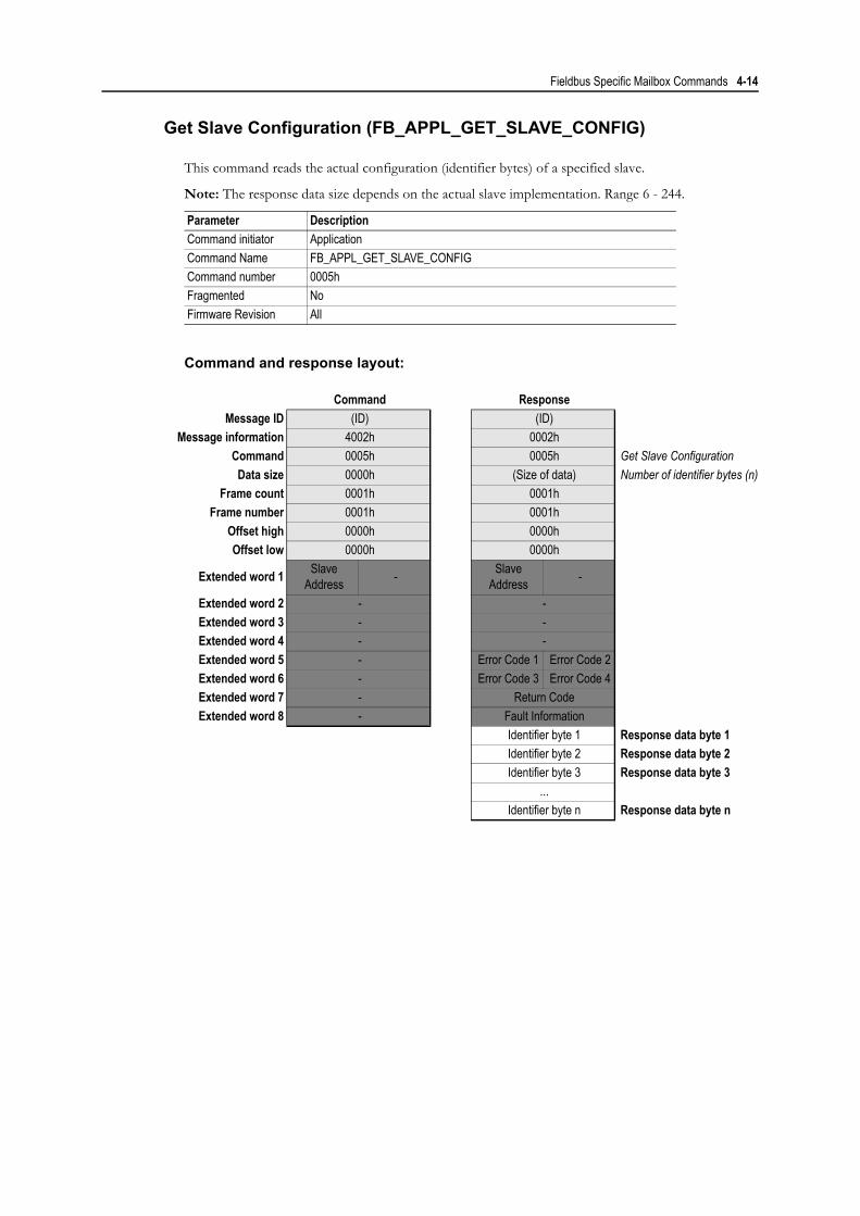
Get Slave Configuration (FB_APPL_GET_SLAVE_CONFIG)
This command reads the actual configuration (identifier bytes) of a specified slave.
Note: The response data size depends on the actual slave implementation. Range 6 - 244.
Command and response layout:
Parameter DescriptionCommand initiator ApplicationCommand Name FB_APPL_GET_SLAVE_CONFIGCommand number 0005hFragmented NoFirmware Revision All
Command ResponseMessage ID (ID) (ID)
Message information 4002h 0002hCommand 0005h 0005h Get Slave ConfigurationData size 0000h (Size of data) Number of identifier bytes (n)
Frame count 0001h 0001hFrame number 0001h 0001h
Offset high 0000h 0000hOffset low 0000h 0000h
Extended word 1 Slave Address - Slave
Address -
Extended word 2 - -Extended word 3 - -Extended word 4 - -Extended word 5 - Error Code 1 Error Code 2Extended word 6 - Error Code 3 Error Code 4Extended word 7 - Return CodeExtended word 8 - Fault Information
Identifier byte 1 Response data byte 1Identifier byte 2 Response data byte 2Identifier byte 3 Response data byte 3
...Identifier byte n Response data byte n

Fieldbus Specific Mailbox Commands 4-15
• Slave Address
Range 0-125, specifies the slave to read configuration from.
• Error Code [1 ... 4]
If ‘Return Code’ equals 8030h (‘Negative indication from lower layer’), status values according to the DP-specification may be available in ‘Error Code 1’. Error Codes 2 to 4 are reserved.(See "Return Codes" and "Error Codes" in Appendix A-1 “DP Error Codes”.)
• Return Code
See "Return Codes" in Appendix A-1 “DP Error Codes”.
• Fault Information
If ‘Invalid Other’ is returned in the Message Information word in the header of the response, information about the fault can be found here.0001h: Address out of range.000Ah: Failed to execute request. (See ‘Return Code’ for additional fault information)000Bh: Remote station failure. (See ‘Return Code’ for additional fault information)00FFh: Module offline (not initialised or no valid database).
• Identifier Bytes [1 ... n]
Consult EN50170 Vol 2 for information about the structure of these bytes. Also, consult the documentation for the actual slave for further information.

Fieldbus Specific Mailbox Commands 4-16
Set Slave Address (FB_APPL_SET_SLAVE_ADDRESS)
This command makes it possible to set the node address of a specified slave, provided that the slave supports this feature.
Note: The message data size depends on the actual slave implementation, range 0 - 240 bytes.
Command and response layout:
Parameter DescriptionCommand initiator ApplicationCommand Name FB_APPL_SET_SLAVE_ADDRESSCommand number 0006hFragmented NoFirmware Revision All
Command ResponseMessage ID (ID) (ID)
Message information 4002h 0002hCommand 0006h 0006h Set Slave AddressData size (Size of data) (Size of data) No. of Slave Data bytes (n)
Frame count 0001h 0001hFrame number 0001h 0001h
Offset high 0000h 0000hOffset low 0000h 0000h
Extended word 1 Current Slave Addr.
New Slave Address
Current Slave Addr.
New Slave Address
Extended word 2 Slave Ident Number Slave Ident NumberExtended word 3 No_add_Chg - No_add_Chg -Extended word 4 - -Extended word 5 - Error Code 1 Error Code 2Extended word 6 - Error Code 3 Error Code 4Extended word 7 - Return CodeExtended word 8 - Fault Information
Message Data byte 1 Slave Data 1 Slave Data 1Message Data byte 2 Slave Data 2 Slave Data 2Message Data byte 3 Slave Data 3 Slave Data 3
... ... ...Message Data byte ‘n’ Slave Data n Slave Data n

Fieldbus Specific Mailbox Commands 4-17
• Current Slave Address
Range 0-125, specifies the current address of the slave
• New Slave Address
Range 0-125, specifies the new address of the slave
• Slave Ident Number
Ident number for the slave, which address should be altered
• No_add_Chg
This parameter specifies whether it is allowed to change the slave address again at a later stage. If this is not allowed, then it is only possible to change the address with this function after initial reset. After the initial reset the slave takes the default address 126.00h: Change of address is still possible at a later stage01h-FFh: Change of address is only possible after the initial address (i.e. the default address =
126)
• Error Code [1 ... 4]
If ‘Return Code’ equals 8030h (‘Negative indication from lower layer’), status values according to the DP-specification is available in ‘Error Code 1’. Error Codes 2 to 4 are reserved.(See "Return Codes" and "Error Codes" in Appendix A-1 “DP Error Codes”.)
• Return Code
See "Return Codes" in Appendix A-1 “DP Error Codes”.
• Fault Information
If ‘Invalid Other’ is returned in the Message Information word in the header of the response, information about the fault can be found here.0001h: Current slave address out of range.0002h: New slave address out of range.000Ah: Failed to execute request. (See ‘Return Code’ for additional fault information)000Bh: Remote station failure. (See ‘Return Code’ for additional fault information)00FFh: Module offline (not initialised or no valid database).
• Slave Data
With this parameter it is possible to deliver user specific data. The data is stored in the slave if possible (i.e. EEPROM, FLASH etc.)
Fieldbus Specific Mailbox Commands 4-18
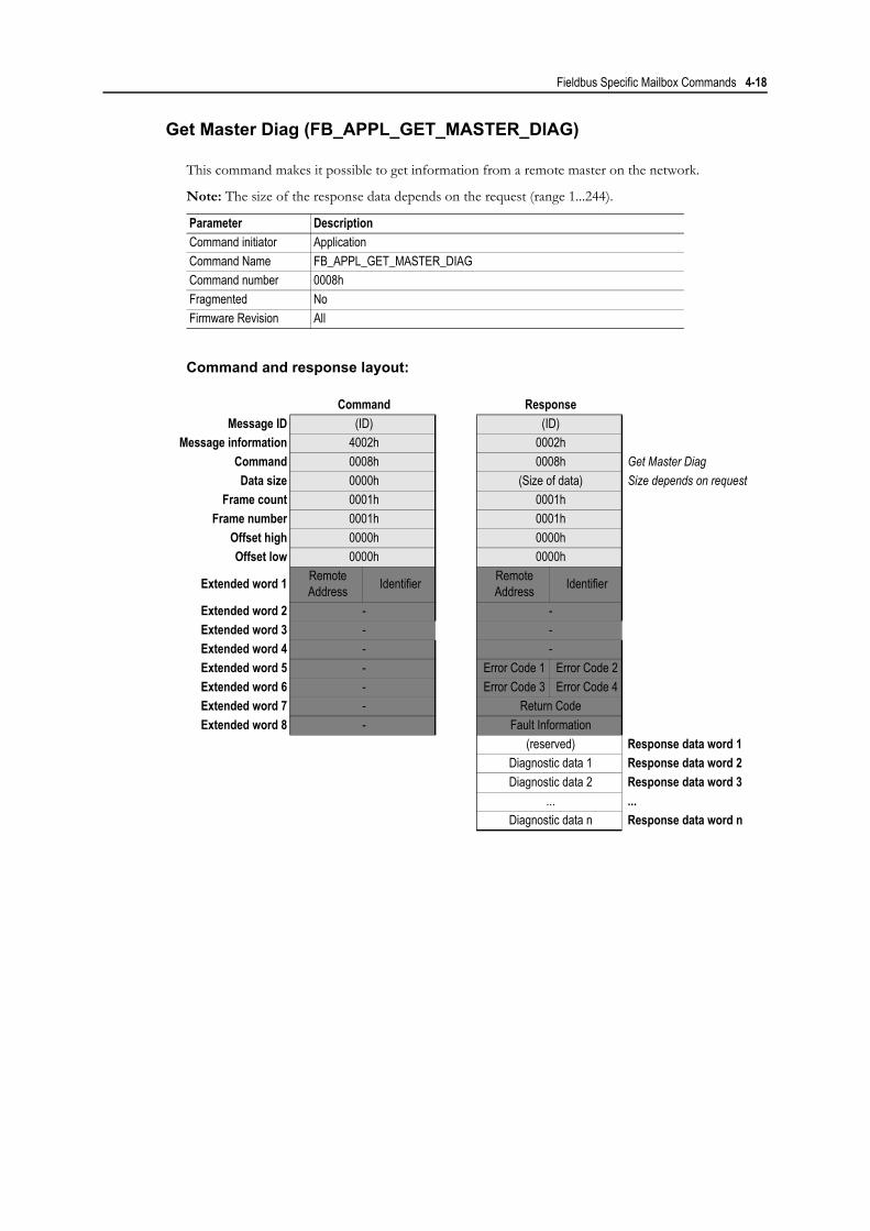
Get Master Diag (FB_APPL_GET_MASTER_DIAG)
This command makes it possible to get information from a remote master on the network.
Note: The size of the response data depends on the request (range 1...244).
Command and response layout:
Parameter DescriptionCommand initiator ApplicationCommand Name FB_APPL_GET_MASTER_DIAGCommand number 0008hFragmented NoFirmware Revision All
Command ResponseMessage ID (ID) (ID)
Message information 4002h 0002hCommand 0008h 0008h Get Master DiagData size 0000h (Size of data) Size depends on request
Frame count 0001h 0001hFrame number 0001h 0001h
Offset high 0000h 0000hOffset low 0000h 0000h
Extended word 1 Remote Address Identifier Remote
Address Identifier
Extended word 2 - -Extended word 3 - -Extended word 4 - -Extended word 5 - Error Code 1 Error Code 2Extended word 6 - Error Code 3 Error Code 4Extended word 7 - Return CodeExtended word 8 - Fault Information
(reserved) Response data word 1Diagnostic data 1 Response data word 2Diagnostic data 2 Response data word 3
... ...Diagnostic data n Response data word n

Fieldbus Specific Mailbox Commands 4-19
• Remote Address
Range 0-125, specifies the address of the master from which the diagnostic information shall be requested.
• Identifier
This parameter specifies the type information to request:
• Error Code [1 ... 4]
If ‘Return Code’ equals 8030h (‘Negative indication from lower layer’), status values according to the DP-specification is available in ‘Error Code 1’. Error Codes 2 to 4 are reserved.(See "Return Codes" and "Error Codes" in Appendix A-1 “DP Error Codes”.)
• Return Code
See "Return Codes" in Appendix A-1 “DP Error Codes”.
• Fault Information
If ‘Invalid Other’ is returned in the Message Information word in the header of the response, information about the fault can be found here.0001h: Current slave address out of range.000Ah: Failed to execute request (See ‘Return Code’ for additional fault information).000Bh: Remote station failure (See ‘Return Code’ for additional fault information).00FFh: Module offline (not initialised or no valid database).
• Diagnostic Data
(Consult EN50170 Volume 2 for further information).
Value Diagnostic Information0...125 Diagnostic data of the DP-Slave with node address 0-125126 System Diagnostics127 Master Status128 Data Transfer List129...255 Reserved

Fieldbus Specific Mailbox Commands 4-20
Get Live List (FB_APPL_GET_LIVE_LIST)
This command returns 127 bytes of information about the nodes on the network. Every byte stands for one bus subscriber, and the position of the byte in the response data assigns the address (0-126), the contents assigns the Station Type (See below).
This command can be sent in all operation modes (i.e. STOP, CLEAR and OPERATE), however the module must be initialised properly with a valid database downloaded.
Command and response layout:
• Station Type [0 ... 126]
00h: Slave Station01h: Master Station not yet ready for Token ring (station only physically at the bus)02h: Master Station ready to enter Token ring (there is not yet any Token transmission)03h: Master Station in Token ring (Token transmission through the station)04h: Station does not exist
• Fault Information
If ‘Invalid Other’ is returned in the Message Information word in the header of the response, information about the fault can be found here.000Ah: Failed to build Live List.00FFh: Module offline (not initialised or no valid database).
Parameter DescriptionCommand initiator ApplicationCommand Name FB_APPL_GET_LIVE_LISTCommand number 0018hFragmented NoFirmware Revision All
Command ResponseMessage ID (ID) (ID)
Message information 4002h 0002hCommand 0018h 0018h Get Live ListData size 0000h 007Fh 127 bytes of data
Frame count 0001h 0001hFrame number 0001h 0001h
Offset high 0000h 0000hOffset low 0000h 0000h
Extended word 1 - -Extended word 2 - -Extended word 3 - -Extended word 4 - -Extended word 5 - -Extended word 6 - -Extended word 7 - Return CodeExtended word 8 - Fault Information
Station Type 0 Response Data byte 1Station Type 1 Response Data byte 2Station Type 2 Response Data byte 3
...Station Type 126 Response Data byte 127

Fieldbus Specific Mailbox Commands 4-21
Database Management
(For more information about database management, see 3-1 “Database Management”.)
Start Database Download (FB_APPL_START_DATABASE_DOWNLOAD)
This command indicates the start of database download.
Command and response layout:
• Application Specific Error Code
This register is only applicable if this message is sent from an external tool via the serial config-uration port and can in that case contain an application specific status code returned from the application using the module. Also see chapter 4-33 “Download New Database Request (FB_ABM_DOWNLOAD_NEW_DB_REQ)”.
• Fault Information
If ‘Invalid Other’ is returned in the Message Information word in the header of the response, information about the fault can be found here.0001h: Command not allowed in this operating mode (only allowed in ‘STOP’ and
‘OFFLINE’ mode)0002h: Application does not permit the download of a new database. Additional information
may be available in ‘Application Specific Error Code’, see below.0003h: Timeout or incorrect answer to ‘FB_ABM_DOWNLOAD_NEW_DB_REQ’ mail-
box
Parameter DescriptionCommand initiator ApplicationCommand Name FB_APPL_START_DATABASE_DOWNLOADCommand number 0010hFragmented NoFirmware Revision All
Command ResponseMessage ID (ID) (ID)
Message information 4002h 0002hCommand 0010h 0010h Start Database DownloadData size 0000h 0000h
Frame count 0001h 0001hFrame number 0001h 0001h
Offset high 0000h 0000hOffset low 0000h 0000h
Extended word 1 - -Extended word 2 - -Extended word 3 - -Extended word 4 - -Extended word 5 - -Extended word 6 - -
Extended word 7 - Application Specific Error Code
Extended word 8 - Fault Information

Fieldbus Specific Mailbox Commands 4-22
End Database Download (FB_APPL_END_DATABASE_DOWNLOAD)
This command ends the database download. When the module recognize this command, it will do an error check of the downloaded database.
It is also possible to store a text string (Message Data word 1-32) that describes the database (example: filename, time/date, configuration tool type/version etc). This text string can then be read back with the ‘FB_APPL_GET_DATABASE_INFO’ message.
Command and response layout:
• Database Description (Optional)
Optional field. String of ASCII characters that describes the data base file. It is recommended to null-terminate the string after the last character.
• Fault Information
If ‘Invalid Other’ is returned in the Message Information word in the header of the response, information about the fault can be found here.0001h: Command not allowed in this operating mode (only allowed in ‘STOP’ and
‘OFFLINE’ mode).0002h: ‘FB_APPL_START_DATABASE_DOWNLOAD’ not sent.0003h: No master record downloaded.0008h: No slave record downloaded.
Parameter DescriptionCommand initiator ApplicationCommand Name FB_APPL_END_DATABASE_DOWNLOADCommand number 0011hFragmented NoFirmware Revision All
Command ResponseMessage ID (ID) (ID)
Message information 4002h 0002hCommand 0011h 0011h End Database DownloadData size (Size of data) 0000h
Frame count 0001h 0001hFrame number 0001h 0001h
Offset high 0000h 0000hOffset low 0000h 0000h
Extended word 1 - -Extended word 2 - -Extended word 3 - -Extended word 4 - -Extended word 5 - -Extended word 6 - -Extended word 7 - -Extended word 8 - Fault Information
Message Data word 1 - 32 Database Description(ASCII, 64 characters)

Fieldbus Specific Mailbox Commands 4-23
Master Record Download (FB_APPL_MASTER_RECORD_DOWNLOAD)
This command allows handling over the master bus parameter set. For more information about the mes-sage data contents, see 3-3 “Master Record Data Structure”
Command and response layout:
Parameter DescriptionCommand initiator ApplicationCommand Name FB_APPL_MASTER_RECORD_DOWNLOADCommand number 0012hFragmented NoFirmware Revision All
Command ResponseMessage ID (ID) (ID)
Message information 4002h 0002hCommand 0012h 0012h Master Record DownloadData size 0060h 0000h
Frame count 0001h 0001hFrame number 0001h 0001h
Offset high 0000h 0000hOffset low 0000h 0000h
Extended word 1 - -Extended word 2 - -Extended word 3 - -Extended word 4 - -Extended word 5 - -Extended word 6 - -Extended word 7 - Extended Fault InformationExtended word 8 - Fault Information
Message Data words 1 - 16 Bus Parameter Data
Message Data word 17 - 48 Master User Data

Fieldbus Specific Mailbox Commands 4-24
• Bus Parameter Data
See 3-3 “Bus Parameter Data Block”
• Master User Data
See 3-5 “Master User Data Block”
• Fault Information
If ‘Invalid Other’ is returned in the Message Information word in the header of the response, information about the fault can be found here.0001h Command not allowed in this operating mode (only allowed in ‘STOP’ and
‘OFFLINE’ mode)0002h ‘FB_APPL_START_DATABASE_DOWNLOAD’ has not been sent to the module0003h Cannot overwrite old configuration, delete database first.0016h Error in Bus Parameter Data (Message Dataword 1-16)0017h Error in Master User Data (Message Data word 17 - 48)
• Extended Fault Information
This word contains further information that points out the faulty parameter.0007h: Reserved parameter not set to zero!0030h: Invalid TS0031h: Invalid Data Rate0032h: Invalid TSL0033h: Invalid minTSDR0034h: Invalid maxTSDR0035h: Invalid TQUI0036h: Invalid TSET0037h: Invalid TTTR0038h: Invalid GAP0039h: Invalid HSA003Ah: Invalid Max retry limit003Bh: Invalid BP_Flag003Ch: Invalid Min_Slave_Interval003Dh: Invalid Poll_Timeout003Eh: Invalid Data_Control_Time003Fh: Invalid Alarm_Max0040h: Invalid Max_UGC0050h: Invalid Master_User_Data_Length0051h: Invalid Tid10052h: Invalid Tid20054h: Invalid Delta_TTR0056h: Invalid Repeater0057h: Invalid Addressing Mode0058h: Invalid Storage Format0059h: Invalid TCT005Ah: Invalid maxTSH

Fieldbus Specific Mailbox Commands 4-25
Master Record Upload (FB_APPL_MASTER_RECORD_UPLOAD)
This command allows read back of the master bus parameter set. For more information about the re-sponse data contents, see 3-3 “Master Record Data Structure”
Command and response layout:
• Bus Parameter Data
See 3-3 “Bus Parameter Data Block”
• Master User Data
See 3-5 “Master User Data Block”
• Fault Information
If ‘Invalid Other’ is returned in the Message Information word in the header of the response, information about the fault can be found here.0001h: No database in flash (or download in progress)
Parameter DescriptionCommand initiator ApplicationCommand Name FB_APPL_MASTER_RECORD_UPLOADCommand number 0013hFragmented NoFirmware Revision All
Command ResponseMessage ID (ID) (ID)
Message information 4002h 0002hCommand 0013h 0013h Master Record UploadData size 0000h 0060h
Frame count 0001h 0001hFrame number 0001h 0001h
Offset high 0000h 0000hOffset low 0000h 0000h
Extended word 1 - -Extended word 2 - -Extended word 3 - -Extended word 4 - -Extended word 5 - -Extended word 6 - -Extended word 7 - -Extended word 8 - Fault Information
Bus Parameter Data Response Data words 1 - 16
Master User Data Response Data word 17 - 48

Fieldbus Specific Mailbox Commands 4-26
Slave Record Download (FB_APPL_SLAVE_RECORD_DOWNLOAD)
This command allows handling over the slave parameter set. At least one mailbox must be downloaded per slave that is to be configured. If the slave record contains more than 256 bytes, it must be subdivided into several fragments.
Each fragment is sent in using the ‘FB_APPL_SLAVE_RECORD_DOWNLOAD’ command. The messages must be sent in successive order, e.g. if the record is divided in 2 fragments, the first message should have ‘Fragment number’ set to 1 and ‘Number of Fragments’ set to 2, and the second should have both parameters set to 2. If only one mailbox is needed to send the record, both ‘Fragment number’ and ‘Number of Fragments’ should be set to 1. A record can be divided in fragments smaller than 256 bytes.
Note: All 16/32-bit parameters must be properly aligned to even addresses. If a 16/32 bit parameter needs to be aligned, a “pad” byte must be inserted (set to zero) on the odd address. Pay special attention to Config_Data_Len and Add_Tab_Len since these parameters are located after byte arrays that might contain an odd number of bytes. Note that if pad bytes are inserted, Slave_Para_Len must not include these pad bytes.
For more information about the message data contents, see 3-6 “Slave Record Data Structure”.
Command and response layout:
Parameter DescriptionCommand initiator ApplicationCommand Name FB_APPL_SLAVE_RECORD_DOWNLOADCommand number 0014hFragmented Yes (see description above)Firmware Revision All
Command ResponseMessage ID (ID) (ID)
Message information 4002h 0002hCommand 0014h 0014h Slave Record DownloadData size (Dynamic, max. 0100h) 0000h
Frame count 0001h 0001hFrame number 0001h 0001h
Offset high 0000h 0000hOffset low 0000h 0000h
Extended word 1 Node Address
FragmentNumber
Node Address
FragmentNumber Fragment information
Extended word 2 Number.of Fragments - Number of
Fragments - - “ -
Extended word 3 - -Extended word 4 - -Extended word 5 - -Extended word 6 - -Extended word 7 - Extended Fault InformationExtended word 8 - Fault Information
Message Data words 1..8 General Data BlockMessage Data words 9...n Parameter Data Block
Message Data words n+1...m Configuration Data BlockMessage Data words m+1...x Address Table BlockMessage Data words x+1...y Slave User Data BlockMessage Data words y+1...z Extended User Param. Data

Fieldbus Specific Mailbox Commands 4-27
• Fault Information
If ‘Invalid Other’ is returned in the Message Information word in the header of the response, information about the fault can be found here.0001h: Command is not allowed in this operation mode (only allowed in ‘STOP’ and
‘OFFLINE’ mode)0002h: The ‘FB_APPL_START_DATABASE_DOWNLOAD’ mailbox has not been sent0003h: Cannot overwrite old configuration, delete database first0004h: Node address is out of range0005h: Failed to allocate buffer to store temporary data0006h: ‘Data size’ in header does not match the actual message data size0009h: Unexpected node address (sending of a fragmented slave record is interrupted)000Ah: Data for this slave already downloaded000Bh: Invalid number of fragments000Ch: Invalid fragment number0010h: Error in Gen_Data0011h: Error in Prm_Data0012h: Error in Cfg_Data0013h: Error in Add_Tab0014h: Error in Slave_User_Data0015h: Error in Ext_User_Prm_Data
• Extended Fault Information
This word contains further information that points out the exact faulty parameter.0007h: Reserved parameter does not equal zero0020h: Invalid Slave_Para_Len0021h: Invalid Slave_Type0022h: Invalid Sl_Flag0023h: Invalid Max_Diag_Data_Len0025h: Invalid Max_Channel_Data_Len0026h: Invalid Diag_Upd_Delay0027h: Invalid Alarm_Mode0028h: Invalid Add_Sl_Flag0029h: Invalid Special functions
• Node Address
Address of the slave associated with the database entry
• Fragment Number
Range 1-255, specifies the current fragment number.
• Number of Fragments
Range 1-255, specifies the total number of fragments needed to send the whole slave record.
• General Data Block
See 3-6 “General Data Block”
• Parameter Data
See 3-7 “Parameter Data Block”
• Configuration Data
See 3-7 “Configuration Data Block”
• Address Table Block
See 3-8 “Address Table Block”
• Slave User Data Block
See 3-8 “Slave User Data Block”
• Extended User Parameter Data
See 3-8 “Extended User Parameter Data Block”

Fieldbus Specific Mailbox Commands 4-28
Slave Record Upload (FB_APPL_SLAVE_RECORD_UPLOAD)
The current slave parameter set can be uploaded from the module using this command. If the data size of the slave that is being accessed is greater than 256 bytes, the module will transfer the message as mul-tiple fragments. The total number of fragments required to transfer the record is indicated by ‘Number of Fragments’. The application specifies what fragment to read in ‘Fragment Number’. The first mailbox that is issued should have ‘Fragment Number’ set to 1, and the second should have 2 etc. until ‘Fragment Number’ equals ‘Number of Fragments’. If for example the total data size of the slave record is 550 bytes, the first and second mailbox will contain 256 bytes and the last one 38 bytes.
Furthermore, pad bytes might be added after the Parameter Data and Configuration Data blocks. The reason for this is that word-sized parameters must be properly aligned to an even address.
For more information about the response data contents, see 3-6 “Slave Record Data Structure”
Command and response layout:
Parameter DescriptionCommand initiator ApplicationCommand Name FB_APPL_SLAVE_RECORD_UPLOADCommand number 0015hFragmented Yes (see description above)Firmware Revision All
Command ResponseMessage ID (ID) (ID)
Message information 4002h 0002hCommand 0015h 0015h Slave Record UploadData size 0000h (Dynamic, max. 0100h)
Frame count 0001h 0001hFrame number 0001h 0001h
Offset high 0000h 0000hOffset low 0000h 0000h
Extended word 1 Node Address
FragmentNumber
Node Address
FragmentNumber Fragment information
Extended word 2 - Number of Fragments - - “ -
Extended word 3 - -Extended word 4 - -Extended word 5 - -Extended word 6 - -Extended word 7 - -Extended word 8 - Fault Information
General Data Block Response Data words 1..8Parameter Data Block Response Data words 9...n
Configuration Data Block Response Data words n+1...mAddress Table Block Response Data words m+1...x
Slave User Data Block Response Data words x+1...yExtended User Parameter
Data Response Data words y+1...z

Fieldbus Specific Mailbox Commands 4-29
• Node Address
Address of the slave associated with the database entry. Range 0...125.
• Fragment Number
Range 1-255, specifies the current fragment number.
• Number of Fragments
Range 1-255, specifies the total number of fragments needed to send the whole slave record.
• General Data Block
See 3-6 “General Data Block”
• Parameter Data
See 3-7 “Parameter Data Block”
• Configuration Data
See 3-7 “Configuration Data Block”
• Address Table Block
See 3-8 “Address Table Block”
• Slave User Data Block
See 3-8 “Slave User Data Block”
• Extended User Parameter Data
See 3-8 “Extended User Parameter Data Block”
• Fault Information
If ‘Invalid Other’ is returned in the Message Information word in the header of the response, information about the fault can be found here.0001h: No database in flash, or download in progress0002h: There is no configuration for this slave0004h: Node address is out of range0005h: Out of memory000Ch: Invalid Fragment Number

Fieldbus Specific Mailbox Commands 4-30
Delete Database (FB_APPL_DELETE_DATABASE)
This command allows deletion of the entire database stored in non-volatile memory. This command can only be sent after the ‘FB_APPL_START_DATABASE_DOWNLOAD’ message. Also see chapter 3-1 “Database Management” for more information.
Command and response layout:
• Fault Information
If ‘Invalid Other’ is returned in the Message Information word in the header of the response, information about the fault can be found here.0001h: Command is not allowed in this operating mode (only allowed in ‘STOP’ and
‘OFFLINE’ mode)0002h: The ‘FB_APPL_START_DATABASE_DOWNLOAD’ mailbox has not been sent
to the module
Parameter DescriptionCommand initiator ApplicationCommand Name FB_APPL_DELETE_DATABASECommand number 0016hFragmented NoFirmware Revision All
Command ResponseMessage ID (ID) (ID)
Message information 4002h 0002hCommand 0016h 0016h Delete DatabaseData size 0000h 0000h
Frame count 0001h 0001hFrame number 0001h 0001h
Offset high 0000h 0000hOffset low 0000h 0000h
Extended word 1 - -Extended word 2 - -Extended word 3 - -Extended word 4 - -Extended word 5 - -Extended word 6 - -Extended word 7 - -Extended word 8 - Fault Information

Fieldbus Specific Mailbox Commands 4-31
Get Database Info (FB_APPL_GET_DATABASE_INFO)
This command fetches information about the stored database. (I.e. User specific data that was down-loaded to the module in the Message Data 1-32 via mailbox ‘FB_APPL_END_DATABASE_DOWNLOAD’ or from the configuration tool.)
This message also returns information about the amount of allocated I/O-data in the input- and output areas. These sizes can be used by the application to set up the I/O-lengths for the ANYBUS_INIT mes-sage.
Command and response layout:
Parameter DescriptionCommand initiator ApplicationCommand Name FB_APPL_GET_DATABASE_INFOCommand number 0017hFragmented NoFirmware Revision All
Command ResponseMessage ID (ID) (ID)
Message information 4002h 0002hCommand 0017h 0017h Get Database InfoData size 0000h 0040h
Frame count 0001h 0001hFrame number 0001h 0001h
Offset high 0000h 0000hOffset low 0000h 0000h
Extended word 1 - Total Output LengthExtended word 2 - Total Input LengthExtended word 3 - Init Output sizeExtended word 4 - Init Input sizeExtended word 5 - No. of Slaves -Extended word 6 - -Extended word 7 - -Extended word 8 - Fault Information
Database Description(ASCII, 64 characters) Response Data word 1 - 32

Fieldbus Specific Mailbox Commands 4-32
• Total Input Length, Total Output Length1
The sum of Input/Output lengths for all slaves in the database (in bytes).
• Init Input size, Init Output size1
Required initialization Input/Output sizes for the current database. If the slaves are located in a contiguous block these sizes are the same as total Input/Output lengths.
• Database Description
String of ASCII characters that describes the data base file. This is the string that was written to the database by the ‘FB_APPL_END_DATABASE_DOWNLOAD’ command.
• No. of Slaves
Number of configured slaves in the database.
• Fault Information
If ‘Invalid Other’ is returned in the Message Information word in the header of the response, information about the fault can be found here.0001h: No database in flash, or download in progress
1. Note that these input/output direction refers to the directions and naming used for the DPRAM areas, not to the input/output directions used in the bus database or the NetTool-PB. For more information, please check page 2-4 “‘Input’ and ‘output’ Definitions”.

Fieldbus Specific Mailbox Commands 4-33
Download New Database Request (FB_ABM_DOWNLOAD_NEW_DB_REQ)
This message indicates to the application that the module has received a request to download a new da-tabase with the ‘FB_APPL_START_DATABASE_DOWNLOAD’ message.
The application must provide either a ‘grant’ or a ‘deny’ response to this message within three seconds, otherwise the ‘FB_APPL_START_DATABASE_DOWNLOAD’ message previously received by the module will be answered with a ‘Timeout error’. When the application receives this message, it can per-form specific actions (e.g. changing operating mode to STOP etc.) before the response is sent.
See 4-2 “Fieldbus Specific Initialisation (FB_INIT)” for more information about how to enable this mailbox message.
Command and response layout:
• Application Specific Error Code
If supported by the initiator of the ‘FB_APPL_START_DATABASE_DOWNLOAD’ message this register provides a possibility to return extended status information back to the initiator. The contents of this register is relayed back to the initiator without any modifications and it is the task of the receiver of this register to translate it into useful information.
• Response Information
0000h: Application permits the module to download a new configuration0001h: Application does not permit the module to download a new configuration. An Appli-
cation Specific Error Code can be supplied in Extended Word 7.
Parameter DescriptionCommand initiator Anybus. Application is required to respond.Command Name FB_ABM_DOWNLOAD_NEW_DB_REQCommand number 0019hFragmented NoFirmware Revision All
Command Application ResponseMessage ID (ID) (ID)
Message information 4002h 0002hCommand 0019h 0019h Download New D.B. RequestData size 0000h 0000h
Frame count 0001h 0001hFrame number 0001h 0001h
Offset high 0000h 0000hOffset low 0000h 0000h
Extended word 1 - -Extended word 2 - -Extended word 3 - -Extended word 4 - -Extended word 5 - -Extended word 6 - -
Extended word 7 - Application Specific Error Code
Extended word 8 - Response Information

Fieldbus Specific Mailbox Commands 4-34
Acyclic Communication, Class 1
Class 1 Read (FB_APPL_MSAC1_READ)
This command initiates a DPV1 Class 1 acyclic read request. Consult EN50170 (DPV1) for more infor-mation.
Command and response layout:
Parameter DescriptionCommand initiator ApplicationCommand Name FB_APPL_MSAC1_READCommand number 0020hFragmented NoFirmware Revision All
Command ResponseMessage ID (ID) (ID)
Message information 4002h 0002hCommand 0020h 0020h Class 1 ReadData size 0000h (Size of data) Number of data bytes (n)
Frame count 0001h 0001hFrame number 0001h 0001h
Offset high 0000h 0000hOffset low 0000h 0000h
Extended word 1 Slave Addr. Slot Slave Addr. SlotExtended word 2 Index Length Index LengthExtended word 3 - -Extended word 4 - -
Extended word 5 - - Error Decode
Extended word 6 - Error Code 1 Error Code 2Extended word 7 - Extended Fault informationExtended word 8 - Fault Information
Data 1 Response Data byte 1Data 2 Response Data byte 2Data 3 Response Data byte 3
... ...Data n Response Data byte n

Fieldbus Specific Mailbox Commands 4-35
• Slave Address
Station address of the slave responder
• Slot & Index
Used in the slave to address the desired data block.
• Length
This parameter specifies the number of bytes of the data block that has to be read. If the server data block length is less than requested, the length of the response will be the actual length of the data block. If the server data block is greater or equal, then the response will contain the same amount of data.The slave may answer with an error response if the data access is not allowed.
• Error Decode, Error Code 1 & Error Code 2
If ‘Fault Information’ contains error code 0010h, more information according to the DPV1 spec-ification can be found here.
• Fault Information & Extended Fault Information
If ‘Invalid Other’ is returned in the Message Information word in the header of the response, information about the fault can be found here.
• Data [1 ... n]
Returned data
‘Fault Information’ ‘Extended Fault Information’ Contents0001h Address out of range -000Ah Failed to execute request
Return Code. See B-1 “DPV1 Error Codes”000Bh Remote station failure0010h Remote station DPV1 failurea
a. See ‘Error Decode, Error Code1 & Error Code2’ above.
Function_Number0011h Length out of range (>240 bytes) -0012h Slave does not support DPV1 -0013h Slave not active or not present in configuration -00FEh Command not possible in ‘Class 2-Only’ mode -
00FFh Module offline (not initialised or no valid data-base) -

Fieldbus Specific Mailbox Commands 4-36
Class 1 Write (FB_APPL_MSAC1_WRITE)
This command initiates a DPV1 Class 1 acyclic write request. Consult EN50170 (DPV1) for more in-formation.
Command and response layout:
Parameter DescriptionCommand initiator ApplicationCommand Name FB_APPL_MSAC1_WRITECommand number 0021hFragmented NoFirmware Revision All
Command ResponseMessage ID (ID) (ID)
Message information 4002h 0002hCommand 0021h 0021h Class 1 WriteData size (Size of data) (Size of data) Number of data bytes (n)
Frame count 0001h 0001hFrame number 0001h 0001h
Offset high 0000h 0000hOffset low 0000h 0000h
Extended word 1 Slave Addr. Slot Slave Addr. SlotExtended word 2 Index Length Index LengthExtended word 3 - -Extended word 4 - -
Extended word 5 - - Error Decode
Extended word 6 - Error Code 1 Error Code 2Extended word 7 - Extended Fault informationExtended word 8 - Fault Information
Message Data byte 1 Data 1 Data 1Message Data byte 2 Data 2 Data 2Message Data byte 3 Data 3 Data 3
... ... ...Message Data byte n Data n Data n

Fieldbus Specific Mailbox Commands 4-37
• Slave Address
Station address of the slave responder
• Slot & Index
Used in the slave to address the desired data block.
• Length
This parameter specifies the number of bytes that has to be written. If the destination data block size is less than required, the response will contain an error message. If the data block length is greater than or equal to the required length, the response contains the number of bytes that has been written. The slave may answer with an error response if the data access is not allowed.
• Error Decode, Error Code 1 & Error Code 2
If ‘Fault Information’ contains error code 0010h, more information according to the DPV1 spec-ification can be found here.
• Fault Information & Extended Fault Information
If ‘Invalid Other’ is returned in the Message Information word in the header of the response, information about the fault can be found here.
• Data [1 ... n]
Data that shall be written.
‘Fault Information’ Contents ‘Extended Fault Information’ Contents0001h Address out of range -000Ah Failed to execute request
Return Code. See B-1 “DPV1 Error Codes”000Bh Remote station failure0010h Remote station DPV1 failurea
a. See ‘Error Decode, Error Code1 & Error Code2’ above.
Function_Number
0011hToo much data is supplied to the slave (more than specified by parameterMax_Channel_Data_Len in database)
-
0012h Slave does not support DPV1 -0013h Slave not active or not present in configuration -00FEh Command not possible in ‘Class 2-Only’ mode -
00FFh Module offline (not initialised or no valid data-base) -

Fieldbus Specific Mailbox Commands 4-38
PROFIdrive V3 Acyclic Parameter Access (FB_APPL_MSAC1_PROFIDRIVE_V3_PARAM_WRITE)
This command initiates a PROFIdrive V3 acyclic parameter request. Consult PROFIdrive V3 for de-tailed information.
This mailbox will issue an acyclic Write command and poll the response using acyclic Read commands until the slave has generated an answer to the request, see figure below.
Parameter DescriptionCommand initiator ApplicationCommand Name FB_APPL_MSAC1_PROFIDRIVE_V3_PARAM_WRITECommand number 0024hFragmented NoFirmware Revision All
SLAVEMASTER (ABM-DPV)
Parameterrequest
Write.req DB47with data (parameter request)
Parameterrequest
Parameterresponse
Write.reswithout data
Read.req DB47without data
Read.res (-)without data
Read.req DB47without data
Read.res (+)with data (parameter response)
...
Parameterresponse
Wait "Poll delay time" beforeissuing next poll.
Read.req DB47without data
Read.res (-)without data

Fieldbus Specific Mailbox Commands 4-39
Command and response layout:
• Slave Address
Station address of the slave responder
• Slot
In PROFIdrive this field is not used.
• Index
In PROFIdrive this field is not used, and should be set to 2Fh.
• Length
This parameter specifies the number of bytes that should be written. If the destination data block is smaller than required, the response will contain an error message (Error Code 1, Error Code 2). If the data block length is greater than or equal to the required length, the response contains the number of bytes that has been written.The slave may answer with an error response if the data access is not allowed.
• Poll Delay Time
Range: 5ms - 65535ms.Delay time between two read polls of the response.
• Maximum Number of Polls
Maximum number of polls that shall be completed before stop polling the module.Range: 1 - 65535 polls
Command ResponseMessage ID (ID) (ID)
Message information 4002h 0002hCommand 0024h 0024h Profidrive v3 Acyclic Par. Acc. Data size (request length) (response length)
Frame count 0001h 0001hFrame number 0001h 0001h
Offset high 0000h 0000hOffset low 0000h 0000h
Extended word 1 Slave Addr. Slot Slave Addr. SlotExtended word 2 Index Length Index LengthExtended word 3 Poll Delay Time Poll Delay TimeExtended word 4 Maximum Number of Polls Maximum Number of Polls
Extended word 5 - Function number
Error Decode
Extended word 6 - Error code 1 Error code 2Extended word 7 - Return CodeExtended word 8 - Fault Information
Message Data byte 1 S_Data 1 R_Data 1 Message Data byte 1Message Data byte 2 S_Data 2 R_Data 2 Message Data byte 2Message Data byte 3 S_Data 3 R_Data 3 Message Data byte 3
... ... ... ...Message Data byte n S_Data n R_Data m Message Data byte m

Fieldbus Specific Mailbox Commands 4-40
• Function Number, Error Decode, Error Code 1 and Error Code 2
If ‘Fault Information’ contains error code 000Bh, more information according to the DPV1 specification can be found here.
• Return Code
See "Return Codes" in Appendix A-1 “DP Error Codes” and B-1 “DPV1 Error Codes”
• Fault Information
If ‘Invalid Other’ is returned in the Message Information word in the header of the response, information about the fault can be found here.0001h: Address out of range0002h: “Poll delay time” too low0003h: Invalid “Maximum number of polls”0004h: Poll timeout. No response was received from the slave within the specified time.000Ah: Failed to execute request (e.g. node is not online)1000Bh: Remote station failure (e.g. node received the request but didn’t approve it)20011h: Too much data is supplied to the slave (more than specified by parameter
Max_Channel_Data_Len in database)00FEh: Command not possible in ‘Class 2-Only’ mode00FFh: Module offline (not initialised or no valid database)
• S_Data [1 ... n]
Data sent to the slave
• R_Data [1 ... m]
Data returned from the slave
1. See ‘Return Code’ for additional information
2. See ‘Function Number, Error Decode, Error Code 1 & Error Code 2’

Fieldbus Specific Mailbox Commands 4-41
Acyclic Communication, Class 2
Class 2 Connection Initiate (FB_APPL_MSAC2_INITIATE)
This command establishes a DPV1 Class 2 connection to a slave, and must be issued prior to using any of the following functions:
• "Class 2 Connection Abort (FB_APPL_MSAC2_ABORT)"• "Class 2 Read (FB_APPL_MSAC2_READ)"• "Class 2 Write (FB_APPL_MSAC2_WRITE)"• "Class 2 Data Transport (FB_APPL_MSAC2_DATA_TRANSPORT)"• "Class 2 Connection Status (FB_APPL_MSAC2_CNXN_STATUS)"
The command supports two modes of operation (Normal or Expert):
• Normal
No message data is included in the command.
• Expert
The application must supply details for the connection (recommended for expert users only).
Note: The command and response layouts for both modes are specified on the following pages.
Parameter DescriptionCommand initiator ApplicationCommand Name FB_APPL_MSAC2_INITIATECommand number 0025hFragmented NoFirmware Revision 2.20 or higher

Fieldbus Specific Mailbox Commands 4-42
Command and response layout (Normal):
Command ResponseMessage ID (ID) (ID)
Message information 4002h 0002hCommand 0025h 0025h FB_APPL_MSAC2_INITIATEData size 0000h (12 + S_Length + D_Length) Size of data in bytes
Frame count 0001h 0001hFrame number 0001h 0001h
Offset high 0000h 0000hOffset low 0000h 0000h
Extended word 1 C_REF C_REF
Extended word 2 Slave Addr. - Slave Addr Max. Data Length
Extended word 3 - Min. Slave Send TimeoutExtended word 4 - -
Extended word 5 - - Error Decode
Extended word 6 - Error Code 1 Error Code 2Extended word 7 - Extended Fault InformationExtended word 8 - Fault Information
Send Timeout Message Data word 1Features
Supported 1Features
Supported 2 Message Data word 2
ProfileFeatures
Supported 1
ProfileFeatures
Supported 2Message Data word 3
Profile Ident Number Message Data word 4S_Type S_Length Message Data word 5D_Type D_Length Message Data word 6
S_Address......
D_Address...Message Data word m

Fieldbus Specific Mailbox Commands 4-43
Command and response layout (Expert):
Command ResponseMessage ID (ID) (ID)
Message information 4002h 0002hCommand 0025h 0025h FB_APPL_MSAC2_INITIATEData size (12 + S_Length + D_Length) (12 + S_Length + D_Length) Size of data in bytes
Frame count 0001h 0001hFrame number 0001h 0001h
Offset high 0000h 0000hOffset low 0000h 0000h
Extended word 1 C_REF C_REF
Extended word 2 Slave Addr. - Slave Addr Max. Data Length
Extended word 3 - Min. Slave Send TimeoutExtended word 4 - -
Extended word 5 - - Error Decode
Extended word 6 - Error Code 1 Error Code 2Extended word 7 - Extended Fault InformationExtended word 8 - Fault Information
Message Data word 1 Send Timeout Send Timeout Response Data word 1
Message Data word 2 Features Supported 1
Features Supported 2
Features Supported 1
Features Supported 2 Response Data word 2
Message Data word 3Profile
Features Supported 1
ProfileFeatures
Supported 2
ProfileFeatures
Supported 1
ProfileFeatures
Supported 2Response Data word 3
Message Data word 4 Profile Ident Number Profile Ident Number Response Data word 4Message Data word 5 S_Type S_Length S_Type S_Length Response Data word 5Message Data word 6 D_Type D_Length D_Type D_Length Response Data word 6
...S_Address S_Address
...... ......
D_Address D_Address...
Message Data word n Response Data word m

Fieldbus Specific Mailbox Commands 4-44
• C_ref
Connections references used to identify the connection later on.Range: 1-128
• Slave Address
Address of the slave to which a connection shall be established. Range: 0...126
• Max. Data Length
The slave’s maximum data length in bytes (reported by the slave in DP Initiate.res).
• Min. Slave Send Timeout
The minimum slave timeout value supported by the slave (in multiples of 10ms).
• Error Decode, Error Code 1 & 2
If ‘Fault Information’ equals 0010h, additional information according to the DPV1 specification can be found here.
• Extended Fault Information
If ‘Fault Information’ equals 000Ah or 000Bh, additional information of the error can be found here. For more information, see B-2 “Class 2-Related Errors”.
• Fault Information
If ‘Invalid Other’ is returned in the Message Information word in the header of the response, information about the fault can be found here.0001h: Address out of range000Ah: Failed to execute request (local error detected). See Extended Fault Information.000Bh: Remote station failure. See Extended Fault Information.0010h: Remote station DPV1 failure. See Error Decode, Error Code 1 & 200FFh: Module not initialised.
• Send Timeout
Defines the control time (timebase 10ms) for the supervision of the connection between the slave and the master.Range 6...65535 (equals 60....655350ms). Default is 1000ms.
• Features Supported 1
Identifies the supported C2-service functionality as follows:b0: DPV1_RW. This bit is set if the services C2_Read and C2_Write are supported.b1...7: (reserved for future use)Default value is 01h.
• Features Supported 2
(reserved for future use)
• Profile Supported 1 & 2
Identifies the supported service functionality regarding the used profile definition. The meaning of these registers are profile- and vendor specific. By default, both are set to 00h.
• Profile Ident Number
This parameter identifies a unique profile definition. The Profile Ident Number is taken from the pool of Ident Numbers managed by the Profibus User Organisation (PNO).Range: 0...65535. 0 = No profile (default).

Fieldbus Specific Mailbox Commands 4-45
• S_Type
This parameter indicates the presence of the optional Network/MAC address of the source.b0: 1: A Network/MAC address is present in S_Address.
0: The source is the endpoint of the connection.b1...7: (reserved for future use)Default value is 00h.
• S_Length
This parameter specifies the length of the S_Address parameter (see table below).Default value is 02h.
• D_Type
This parameter indicates the presence of the optional Network/MAC address of the destination.b0: 1: A Network/MAC address is present in D_Address.
0: The destination (in this case the Anybus module) is the endpoint of the connection.b1...7: (reserved for future use)Default value is 00h.
• D_Length
This value specifies the length of the D_Address parameter (see table below).Default value is 02h.
• S_Address
This field holds additional address information about the source. It’s structure depends on the settings in S_Type.
• D_Address
This field holds additional address information about the destination. It’s structure depends on the settings in D_Type.
S_Type Type Sub–parameter Description
00hUnsigned8 API Identifies the application process instance of the source.Unsigned8 SCL Identifies the access level of the source (0 = not used)
01h
Unsigned8 API Identifies the application process instance of the source.Unsigned8 SCL Identifies the access level of the source.
Octet-string[6] Network Address Identifies the network address of the source according to ISO/OSI-Network addresses.
Octet-string[S_Length - 8] MAC Address Identifies the MAC address of the source
D_Type Type Sub–parameter Description
00hUnsigned8 API Identifies the application process instance of the destination.Unsigned8 SCL Identifies the access level of the destination. (0 = not used)
01h
Unsigned8 API Identifies the application process instance of the destination.Unsigned8 SCL Identifies the access level of the destination.
Octet-string[6] Network Address Identifies the network address of the destination according to ISO/OSI-Network addresses.
Octet-string[D_Length - 8] MAC Address Identifies the MAC address of the destination
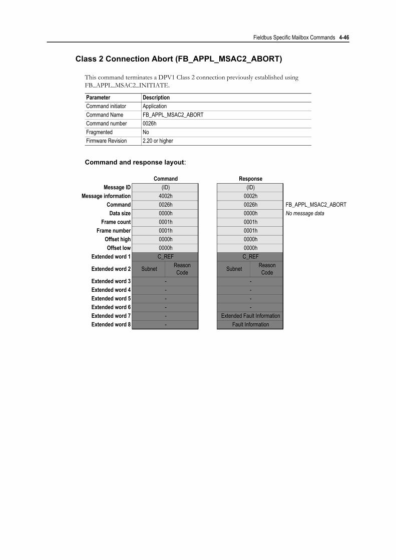
Fieldbus Specific Mailbox Commands 4-46
Class 2 Connection Abort (FB_APPL_MSAC2_ABORT)
This command terminates a DPV1 Class 2 connection previously established using FB_APPL_MSAC2_INITIATE.
Command and response layout:
Parameter DescriptionCommand initiator ApplicationCommand Name FB_APPL_MSAC2_ABORTCommand number 0026hFragmented NoFirmware Revision 2.20 or higher
Command ResponseMessage ID (ID) (ID)
Message information 4002h 0002hCommand 0026h 0026h FB_APPL_MSAC2_ABORTData size 0000h 0000h No message data
Frame count 0001h 0001hFrame number 0001h 0001h
Offset high 0000h 0000hOffset low 0000h 0000h
Extended word 1 C_REF C_REF
Extended word 2 Subnet Reason Code Subnet Reason
CodeExtended word 3 - -Extended word 4 - -Extended word 5 - -Extended word 6 - -Extended word 7 - Extended Fault InformationExtended word 8 - Fault Information

Fieldbus Specific Mailbox Commands 4-47
• C_Ref
Connection reference that shall be terminated.
• Subnet
This parameter encodes information about the origin of the abort initiator.0: No1: Local2: Remote3...255: (reserved)
• Reason Code
Indicates the reason for the abort request. Value is user-specific. Range 0...15.
• Extended Fault Information
If ‘Fault Information’ equals 000Ah or 000Bh, additional information of the error can be found here. For more information, see B-2 “Class 2-Related Errors”.
• Fault Information
If ‘Invalid Other’ is returned in the Message Information word in the header of the response, information about the fault can be found here.000Ah: Failed to execute request (local error detected). See Extended Fault Information.000Bh: Remote station failure. See Extended Fault Information.00FFh: Module not initialised.

Fieldbus Specific Mailbox Commands 4-48
Class 2 Connection Abort Indication (FB_APPL_MSAC2_ABORT_IND)
This message is issued spontaneously by the module when any of the established connections has been aborted for reasons not caused by the application (e.g. slave time-out, connection terminated by slave etc.). This message is not issued when a connection has been terminated using FB_APPL_MSAC2_ABORT.
Note: The application must not respond to this message!
Note: This feature can be disabled, see 4-2 “Fieldbus Specific Initialisation (FB_INIT)”
Message layout:
Parameter DescriptionCommand initiator AnybusCommand Name FB_APPL_MSAC2_ABORT_INDCommand number 002AhFragmented NoFirmware Revision 2.20 or higher
Message ID (ID)Message information 4002h
Command 002Ah FB_APPL_MSAC2_ABORT_INDData size 0000h No message data
Frame count 0001hFrame number 0001h
Offset high 0000hOffset low 0000h
Extended word 1 C_REF
Extended word 2 Subnet Reason Code
Extended word 3 Additional DetailExtended word 4 Locally GeneratedExtended word 5 -Extended word 6 -Extended word 7 -Extended word 8 -

Fieldbus Specific Mailbox Commands 4-49
• C_Ref
Connection reference.
• Subnet
This parameter encodes information about the origin of the abort initiator.0: No1: Local2: Remote3...255: (reserved)
• Instance/Reason
This parameter encodes information about the reason for the abort request, and the protocol in-stance that caused it.
• Additional Detail
This parameter holds the Send_Timeout if the Instance/Reason code equals ABT_STO.
• Locally Generated
This parameter indicates the abort initiator.0: Generated by the remote station1: Generated by the master (local)
b7 b6 b5 b4 b3 b2 b1 b0(reserved) Instance Code Reason Code
Instance Code Reason Code Name Meaning
b00: FDL
1 UE
See EN 50170 part 2
2 RR3 RS9 NR10 DH11 LR12 RDL13 RDH14 DS Master is not in logical ring15 NA No response from remote FDL
b01: C2
1 ABT_SE Sequence error; service not allowed in this state2 ABT_FE Invalid request PDU received3 ABT_TO Timeout of the connection4 ABT_RE Invalid response PDU received5 ABT_IV Invalid service from user6 ABT_STO Send_Timeout requested was too small7 ABT_IA Invalid additional address information8 ABT_OC Waiting or FDL_DATA_REPLY.con15 ABT_RES Resource error
b10: User - - -b11: (reserved) - - -
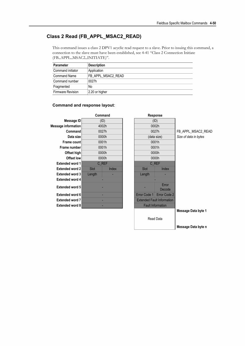
Fieldbus Specific Mailbox Commands 4-50
Class 2 Read (FB_APPL_MSAC2_READ)
This command issues a class 2 DPV1 acyclic read request to a slave. Prior to issuing this command, a connection to the slave must have been established, see 4-41 “Class 2 Connection Initiate (FB_APPL_MSAC2_INITIATE)”.
Command and response layout:
Parameter DescriptionCommand initiator ApplicationCommand Name FB_APPL_MSAC2_READCommand number 0027hFragmented NoFirmware Revision 2.20 or higher
Command ResponseMessage ID (ID) (ID)
Message information 4002h 0002hCommand 0027h 0027h FB_APPL_MSAC2_READData size 0000h (data size) Size of data in bytes
Frame count 0001h 0001hFrame number 0001h 0001h
Offset high 0000h 0000hOffset low 0000h 0000h
Extended word 1 C_REF C_REFExtended word 2 Slot Index Slot IndexExtended word 3 Length - Length -Extended word 4 - -
Extended word 5 - - Error Decode
Extended word 6 - Error Code 1 Error Code 2Extended word 7 - Extended Fault InformationExtended word 8 - Fault Information
Read Data
Message Data byte 1
Message Data byte n

Fieldbus Specific Mailbox Commands 4-51
• C_Ref
Connection reference.
• Slot
Used in the slave for addressing of the desired data block. Range 0...254.
• Index
Used in the slave for addressing of the desired data block. Range 0...254.
• Length
Number of bytes to read.
• Error Decode, Error Code 1 & 2
If ‘Fault Information’ equals 0010h, additional information according to the DPV1 specification can be found here.
• Extended Fault Information
If ‘Fault Information’ equals 000Ah or 000Bh, additional information of the error can be found here. For more information, see B-2 “Class 2-Related Errors”.
• Fault Information
If ‘Invalid Other’ is returned in the Message Information word in the header of the response, information about the fault can be found here.000Ah: Failed to execute request (local error detected). See Extended Fault Information.000Bh: Remote station failure. See Extended Fault Information.0010h: Remote station DPV1 failure. See Extended Fault Information.00FFh: Module not initialised.
• Read Data
Read data.
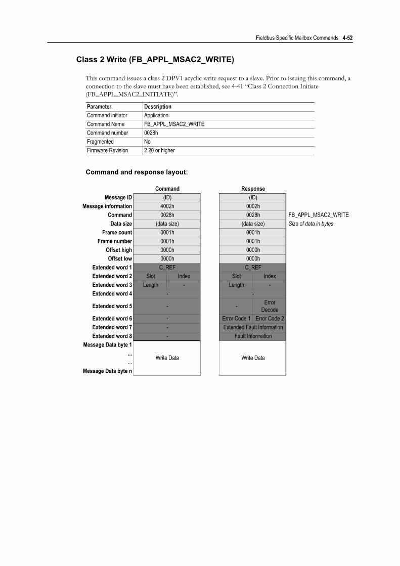
Fieldbus Specific Mailbox Commands 4-52
Class 2 Write (FB_APPL_MSAC2_WRITE)
This command issues a class 2 DPV1 acyclic write request to a slave. Prior to issuing this command, a connection to the slave must have been established, see 4-41 “Class 2 Connection Initiate (FB_APPL_MSAC2_INITIATE)”.
Command and response layout:
Parameter DescriptionCommand initiator ApplicationCommand Name FB_APPL_MSAC2_WRITECommand number 0028hFragmented NoFirmware Revision 2.20 or higher
Command ResponseMessage ID (ID) (ID)
Message information 4002h 0002hCommand 0028h 0028h FB_APPL_MSAC2_WRITEData size (data size) (data size) Size of data in bytes
Frame count 0001h 0001hFrame number 0001h 0001h
Offset high 0000h 0000hOffset low 0000h 0000h
Extended word 1 C_REF C_REFExtended word 2 Slot Index Slot IndexExtended word 3 Length - Length -Extended word 4 - -
Extended word 5 - - Error Decode
Extended word 6 - Error Code 1 Error Code 2Extended word 7 - Extended Fault InformationExtended word 8 - Fault Information
Message Data byte 1
Write Data Write Data......
Message Data byte n

Fieldbus Specific Mailbox Commands 4-53
• C_Ref
Connection reference.
• Slot
Used in the slave for addressing of the desired data block. Range 0...254.
• Index
Used in the slave for addressing of the desired data block. Range 0...254.
• Length
Number of bytes to write.
• Error Decode, Error Code 1 & 2
If ‘Fault Information’ equals 0010h, additional information according to the DPV1 specification can be found here.
• Extended Fault Information
If ‘Fault Information’ equals 000Ah or 000Bh, additional information of the error can be found here. For more information, see B-2 “Class 2-Related Errors”.
• Fault Information
If ‘Invalid Other’ is returned in the Message Information word in the header of the response, information about the fault can be found here.000Ah: Failed to execute request (local error detected). See Extended Fault Information.000Bh: Remote station failure. See Extended Fault Information.0010h: Remote station DPV1 failure. See Extended Fault Information.00FFh: Module not initialised.
• Write Data
Data to write.

Fieldbus Specific Mailbox Commands 4-54
Class 2 Data Transport (FB_APPL_MSAC2_DATA_TRANSPORT)
This command issues a combined class 2 DPV1 acyclic read/write request to a slave. Prior to issuing this command, a connection to the slave must have been established, see 4-41 “Class 2 Connection In-itiate (FB_APPL_MSAC2_INITIATE)”.
Command and response layout:
Parameter DescriptionCommand initiator ApplicationCommand Name FB_APPL_MSAC2_DATA_TRANSPORTCommand number 0028hFragmented NoFirmware Revision 2.20 or higher
Command ResponseMessage ID (ID) (ID)
Message information 4002h 0002hCommand 0028h 0028h FB_APPL_MSAC2_WRITEData size (data size) (data size) Size of data in bytes
Frame count 0001h 0001hFrame number 0001h 0001h
Offset high 0000h 0000hOffset low 0000h 0000h
Extended word 1 C_REF C_REFExtended word 2 Slot Index Slot IndexExtended word 3 Length - Length -Extended word 4 - -
Extended word 5 - - Error Decode
Extended word 6 - Error Code 1 Error Code 2Extended word 7 - Extended Fault InformationExtended word 8 - Fault Information
Message Data byte 1
Write Data Read Data......
Message Data byte n

Fieldbus Specific Mailbox Commands 4-55
• C_Ref
Connection reference.
• Slot
Used in the slave for addressing of the desired data block. Range 0...254.
• Index
Used in the slave for addressing of the desired data block. Range 0...254.
• Length
Number of bytes to read/write.
• Error Decode, Error Code 1 & 2
If ‘Fault Information’ equals 0010h, additional information according to the DPV1 specification can be found here.
• Extended Fault Information
If ‘Fault Information’ equals 000Ah or 000Bh, additional information of the error can be found here. For more information, see B-2 “Class 2-Related Errors”.
• Fault Information
If ‘Invalid Other’ is returned in the Message Information word in the header of the response, information about the fault can be found here.000Ah: Failed to execute request (local error detected). See Extended Fault Information.000Bh: Remote station failure. See Extended Fault Information.0010h: Remote station DPV1 failure. See Extended Fault Information.00FFh: Module not initialised.
• Write Data
Data to write.
• Read Data
Read data.

Fieldbus Specific Mailbox Commands 4-56
Class 2 Connection Status (FB_APPL_MSAC2_CNXN_STATUS)
This command returns the current status of a class 2 DPV1 specific connection. Preferably, this com-mand is used in conjunction with the DPV1 C2 Connection Livelist (see 5-3 “Class 2 Connection Live-List (E80h...E8Fh)”); when the livelist indicates that a connection has been closed, the reason for closing may be determined using this command.
Command and response layout:
Parameter DescriptionCommand initiator ApplicationCommand Name FB_APPL_MSAC2_CNXN_STATUSCommand number 0028hFragmented NoFirmware Revision 2.20 or higher
Command ResponseMessage ID (ID) (ID)
Message information 4002h 0002hCommand 0028h 0028h FB_APPL_MSAC2_WRITEData size (data size) (data size) Size of data in bytes
Frame count 0001h 0001hFrame number 0001h 0001h
Offset high 0000h 0000hOffset low 0000h 0000h
Extended word 1 C_REF C_REFExtended word 2 - Status Add InfoExtended word 3 - -Extended word 4 - -Extended word 5 - -Extended word 6 - -Extended word 7 - Extended Fault InformationExtended word 8 - Fault Information
Subnet Instance/Reason Message Data word 1
Additional Detail Message Data word 2Locally Generated Message Data word 3

Fieldbus Specific Mailbox Commands 4-57
• C_Ref
Connection reference.
• Status
This flag reflects the current status of the specified connection reference (C_Ref).0: No connection, or connection has been closed1: Connection is alive and open.
• Add Info
This flag indicates if additional information is present in Message Data words 1...3.0: No message data1: Message data available
• Extended Fault Information
If ‘Fault Information’ equals 000Ah or 000Bh, additional information of the error can be found here. For more information, see B-2 “Class 2-Related Errors”.
• Fault Information
If ‘Invalid Other’ is returned in the Message Information word in the header of the response, information about the fault can be found here.
000Ah: Failed to execute request (local error detected). See Extended Fault Information.000Bh: Remote station failure. See Extended Fault Information.0010h: Remote station DPV1 failure. See Extended Fault Information.00FFh: Module not initialised.
• Subnet
This parameter encodes information about the origin of the abort initiator.0: No1: Local2: Remote3...255: (reserved)

Fieldbus Specific Mailbox Commands 4-58
• Instance/Reason
This parameter encodes information about the reason for the abort request, and the protocol in-stance that caused it.
• Additional Detail
This parameter holds the Send_Timeout if the Instance/Reason code equals ABT_STO.
• Locally Generated
This parameter indicates the abort initiator.0: Generated by the remote station1: Generated by the master (local)
b7 b6 b5 b4 b3 b2 b1 b0(reserved) Instance Code Reason Code
Instance Code Reason Code Name Meaning
b00: FDL
1 UE
See EN 50170 part 2
2 RR3 RS9 NR10 DH11 LR12 RDL13 RDH14 DS Master is not in logical ring15 NA No response from remote FDL
b01: C2
1 ABT_SE Sequence error; service not allowed in this state2 ABT_FE Invalid request PDU received3 ABT_TO Timeout of the connection4 ABT_RE Invalid response PDU received5 ABT_IV Invalid service from user6 ABT_STO Send_Timeout requested was too small7 ABT_IA Invalid additional address information8 ABT_OC Waiting or FDL_DATA_REPLY.con15 ABT_RES Resource error
b10: User - - -b11: (reserved) - - -

Fieldbus Specific Mailbox Commands 4-59
DPV1 Alarm Handling
Alarm Indication (FB_ABM_MSAL1_ALARM_IND)
This message indicates to the application that a DPV1 slave has transferred an Alarm message to the master. This mailbox message is sent spontaneously by the module, i.e. the module itself initiates the mailbox communication.
Detailed information about the alarm cause is presented in extended words 1 - 3 and in the message data field, see below.
The application must provide a response to this command, which will trigger the module to send an MSAC1_Alarm_Ack to the slave. This will tell the slave that the alarm has been configured by the mas-ter. The slave will in turn respond with a confirmation message, see 4-61 “Alarm Confirmation (FB_ABM_MSAL1_ALARM_CON)”
Note: This feature can be disabled, see 4-2 “Fieldbus Specific Initialisation (FB_INIT)”
Command and response layout:
Parameter DescriptionCommand initiator Anybus. Response required from application.Command Name FB_ABM_MSAL1_ALARM_INDCommand number 0022hFragmented NoFirmware Revision All
Indication Application ResponseMessage ID (ID) (ID)
Message information 4002h 0002hCommand 0022h 0022h Alarm IndicationData size (request length) 0000h
Frame count 0001h 0001hFrame number 0001h 0001h
Offset high 0000h 0000hOffset low 0000h 0000h
Extended word 1 Slave Addr. Slot Number -
Extended word 2 Seq Number Alarm Spec Ack -
Extended word 3 Alarm Type Ext Diag -Extended word 4 - -Extended word 5 - -Extended word 6 - -Extended word 7 - -Extended word 8 Fault Information -
Message Data byte 1 Data 1Message Data byte 2 Data 2Message Data byte 3 Data 3
... ...Message Data byte n Data n

Fieldbus Specific Mailbox Commands 4-60
• Slave Address1
Station address of the slave that indicates the alarm
• Slot Number1
Used by the slave to indicate the source of the alarmRange 0 - 254
• Seq Number1
Unique identification number of the alarmRange 0 - 31
• Alarm Spec Ack1
Gives additional information about the Alarm, such as an error appears, or disappears. It also indicates whether the slave needs additional acknowledge from the Master (Example: Writing to a certain memory area with an Acyclic Write request)Range 0 - 7
• Alarm Type1
Identifies the alarm type, such as Process Alarm, Plug Alarm etc.Range 1 - 6, 32 - 126
• Extended Diagnostic Flag1
FFh: Slave sends an alarm message with “Extended Diag flag” set00h: Slave sends an alarm message with “Extended Diag flag” cleared
• Data [1 ... n]
Additional manufacturer specific alarm information (Alarm - PDU)
• Fault Information
If the Message Information word in the header of the message indicates ‘Invalid Other’, addi-tional information is available in this register.003Eh: Module has received an invalid alarm indication data structure from a DPV1 slave.
(‘Slave Address’ contains the node address of the slave that issued the erroneous in-dication)
Note: The application does not have to respond in this case, since the module can’t send an Alarm Acknowledge to the slave because of this fault.
1. Consult the PNO document ‘Extensions to EN50170 (DPV)’ for more information on how to interpret these parameters.

Fieldbus Specific Mailbox Commands 4-61
Alarm Confirmation (FB_ABM_MSAL1_ALARM_CON)
This message indicates to the application that a slave has confirmed a previous MSAC1_Alarm_Ack, see 4-59 “Alarm Indication (FB_ABM_MSAL1_ALARM_IND)”. This mailbox message is sent spontane-ously by the module, i.e. the module itself initiates the mailbox communication.
Note: The application must not respond to this message!
Note: This feature can be disabled, see 4-2 “Fieldbus Specific Initialisation (FB_INIT)”
Message layout:
Parameter DescriptionCommand initiator Anybus. Application is not required to respond.Command Name FB_ABM_MSAL1_ALARM_CONCommand number 0023hFragmented NoFirmware Revision All
Indication Application ResponseMessage ID (ID) (no response)
Message information 4002hCommand 0023hData size 0000h
Frame count 0001hFrame number 0001h
Offset high 0000hOffset low 0000h
Extended word 1 Slave Addr. Slot Number
Extended word 2 Seq Number Alarm Spec Ack
Extended word 3 Alarm Type Ext DiagExtended word 4 -
Extended word 5 - Error Decode
Extended word 6 Error Code 1 Error Code 2Extended word 7 Extended Fault InformationExtended word 8 Fault Information

Fieldbus Specific Mailbox Commands 4-62
• Slave Address1
Station address of the slave that indicates the alarm
• Slot Number1
Used by the slave to indicate the source of the alarmRange 0 - 254
• Seq Number1
Unique identification number of the alarmRange 0 - 31
• Alarm Spec Ack1
Gives additional information about the Alarm, such as an error appears, or disappears. It also indicates whether the slave needs additional acknowledge from the Master (Example: Writing to a certain memory area with an Acyclic Write request)Range 0 - 7
• Alarm Type1
Identifies the alarm type, such as Process Alarm, Plug Alarm etc.Range 1 - 6, 32 - 126
• Extended Diagnostic Flag1
FFh: Slave sends an alarm message with “Extended Diag flag” set00h: Slave sends an alarm message with “Extended Diag flag” cleared
• Error Decode, Error Code 1 & Error Code 2
If ‘Fault Information’ contains error code 0010h, more information according to the DPV1 spec-ification can be found here.
• Fault Information & Extended Fault Information
If the Message Information word in the header of the message indicates ‘Invalid Other’, addi-tional information is available in this register.
1. Consult the PNO document ‘Extensions to EN50170 (DPV)’ for more information on how to interpret these parameters.
‘Fault Information’ Contents ‘Extended Fault Information’ Contents000Ah Failed to execute request
Return Code. See B-1 “DPV1 Error Codes”000Bh Remote station failure0010h Remote station DPV1 failurea
a. See ‘Error Decode, Error Code1 & Error Code2’ above.
Function_Number

Chapter 5
Fieldbus Specific Area
General
This area holds information about the master and the slaves on the network. Note that all registers in this area is read-only.
Overview
Location: Contents: Access: Comments:
E40h - E4Fh Slave Configured List RO See 5-2 “Slave Configured List (E40h...E4Fh)”
E50h - E5Fh Data Transfer List RO See 5-2 “Data Transfer List (E50h...E5Fh)”
E60h - E6Fh Slave Diagnostic List RO See 5-2 “Slave Diagnostic List (E60h...E6Fh)”
E70h - E76h Master Status Field RO See 5-3 “Master Status Field (E70h...E72h)”
E77h - E7Fh Master Init Field RO See 5-3 “Master Init Field (E77h...E7Ch)”
E80h - E8Fh Class 2 Connection Live-list RO See 5-3 “Class 2 Connection Live-List (E80h...E8Fh)”
E90h - FBFh (debug Info, reserved) RO(This area contains debugging informa-tion that may be useful when contacting technical support)
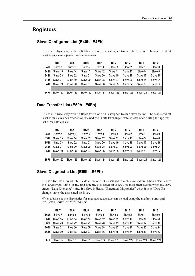
Fieldbus Specific Area 5-2
Registers
Slave Configured List (E40h...E4Fh)
This is a 16-byte array with bit fields where one bit is assigned to each slave station. The associated bit is set if the slave is present in the database.
Data Transfer List (E50h...E5Fh)
This is a 16-byte array with bit fields where one bit is assigned to each slave station. The associated bit is set if the slaves has reached or retained the “Data Exchange” state at least once during the approx. last three data cycles.
Slave Diagnostic List (E60h...E6Fh)
This is a 16-byte array with bit fields where one bit is assigned to each slave station. When a slave leaves the “Deactivate” state for the first time the associated bit is set. This bit is then cleared when the slave enters “Data Exchange” state. If a slave indicates “Extended Diagnostics” when it is in “Data Ex-change” state, the associated bit is set.
When a bit is set the diagnostics for that particular slave can be read using the mailbox command ‘FB_APPL_GET_SLAVE_DIAG’.
Bit 7 Bit 6 Bit 5 Bit 4 Bit 3 Bit 2 Bit 1 Bit 0E40h Slave 7 Slave 6 Slave 5 Slave 4 Slave 3 Slave 2 Slave 1 Slave 0E41h Slave 15 Slave 14 Slave 13 Slave 12 Slave 11 Slave 10 Slave 9 Slave 8E42h Slave 23 Slave 22 Slave 21 Slave 20 Slave 19 Slave 18 Slave 17 Slave 16E43h Slave 31 Slave 30 Slave 29 Slave 28 Slave 27 Slave 26 Slave 25 Slave 24E44h Slave 39 Slave 38 Slave 37 Slave 36 Slave 35 Slave 34 Slave 33 Slave 32
... ... ... ... ... ... ... ... ...E4Fh Slave 127 Slave 126 Slave 125 Slave 124 Slave 123 Slave 122 Slave 121 Slave 120
Bit 7 Bit 6 Bit 5 Bit 4 Bit 3 Bit 2 Bit 1 Bit 0E50h Slave 7 Slave 6 Slave 5 Slave 4 Slave 3 Slave 2 Slave 1 Slave 0E51h Slave 15 Slave 14 Slave 13 Slave 12 Slave 11 Slave 10 Slave 9 Slave 8E52h Slave 23 Slave 22 Slave 21 Slave 20 Slave 19 Slave 18 Slave 17 Slave 16E53h Slave 31 Slave 30 Slave 29 Slave 28 Slave 27 Slave 26 Slave 25 Slave 24E54h Slave 39 Slave 38 Slave 37 Slave 36 Slave 35 Slave 34 Slave 33 Slave 32
... ... ... ... ... ... ... ... ...E5Fh Slave 127 Slave 126 Slave 125 Slave 124 Slave 123 Slave 122 Slave 121 Slave 120
Bit 7 Bit 6 Bit 5 Bit 4 Bit 3 Bit 2 Bit 1 Bit 0E60h Slave 7 Slave 6 Slave 5 Slave 4 Slave 3 Slave 2 Slave 1 Slave 0E61h Slave 15 Slave 14 Slave 13 Slave 12 Slave 11 Slave 10 Slave 9 Slave 8E62h Slave 23 Slave 22 Slave 21 Slave 20 Slave 19 Slave 18 Slave 17 Slave 16E63h Slave 31 Slave 30 Slave 29 Slave 28 Slave 27 Slave 26 Slave 25 Slave 24E64h Slave 39 Slave 38 Slave 37 Slave 36 Slave 35 Slave 34 Slave 33 Slave 32
... ... ... ... ... ... ... ... ...E6Fh Slave 127 Slave 126 Slave 125 Slave 124 Slave 123 Slave 122 Slave 121 Slave 120

Fieldbus Specific Area 5-3
Master Status Field (E70h...E72h)
Master Init Field (E77h...E7Ch)
This field reflects the settings in the FB_INIT mailbox command.
Class 2 Connection Live-List (E80h...E8Fh)
This field reflects the status of all DPV1 Class 2 connections. Each bit in the field corresponds to a single connection reference (C_REF). If set, a connection has been opened and is alive. If zero, the connection has either been terminated or never been opened. In such case, additional information can be read using the mailbox command FB_APPL_MSAC2_CNXN_STATUS (4-56 “Class 2 Connection Status (FB_APPL_MSAC2_CNXN_STATUS)”).
Location Contents Description
E70h Operation State
00h - Offline40h - Stop80h - ClearC0h - Operate
E71h Ident number (msb)PNO Ident number
E72h Ident number (lsb)E73h
(reserved) -E74hE75hE76h
Location Contents DescriptionE77h (reserved) -E78h DPRAM mode See 4-2 “Fieldbus Specific Initialisation (FB_INIT)”E79h (reserved) -E7Ah Special Functions See 4-2 “Fieldbus Specific Initialisation (FB_INIT)”E7Bh (reserved) -E7Ch Start-up Operating Mode See 4-2 “Fieldbus Specific Initialisation (FB_INIT)”E7Dh
(reserved) -E7EhE7Fh
Bit 7 Bit 6 Bit 5 Bit 4 Bit 3 Bit 2 Bit 1 Bit 0E80h C_REF 8 C_REF 7 C_REF 6 C_REF 5 C_REF 4 C_REF 3 C_REF 2 C_REF 1E81h C_REF 16 C_REF 15 C_REF 14 C_REF 13 C_REF 12 C_REF 11 C_REF 10 C_REF 9E82h C_REF 24 C_REF 23 C_REF 22 C_REF 21 C_REF 20 C_REF 19 C_REF 18 C_REF 17E83h C_REF 32 C_REF 31 C_REF 30 C_REF 29 C_REF 28 C_REF 27 C_REF 26 C_REF 25E84h C_REF 40 C_REF 39 C_REF 38 C_REF 37 C_REF 36 C_REF 35 C_REF 34 C_REF 33
... ... ... ... ... ... ... ... ...E8Fh C_REF 128 C_REF 127 C_REF 126 C_REF 125 C_REF 124 C_REF 123 C_REF 122 C_REF 121

Chapter 6
Control Register Area
General
The contents of this area is thoroughly described in the Anybus-S Parallel Design Guide. This chapter describes how to interpret the information when using the Anybus-M Profibus DPV1 module.
Note that all registers in this area is read-only.
Registers
Module Status Register (FE2h...FE3h)
Changed Data Field (FECh...FEBh)
This field is not used by the Anybus-M Profibus DPV.
b15 b14 b13 b12 b11 b10 b9 b8 b7 b6 b5 b4 b3 b2 b1 b0(reserved) APRS CD APFC (reserved) RDR FBSPU FBS FBFC FBRS
(MSB) (LSB)
• FBRS
0: There is Data Exchange with any of the assigned slaves
1: There is Data Exchange with at least one of the assigned slaves
• FBFC
0: Data from a slave in the OUT area are cleared if a slave is not in Data Exchange
1: Data from a slave in the OUT area are frozen if a slave is not in Data Exchange
• FBS
-: (Not used, set to zero)
• FBSPU
-: (Not used, set to zero)
• RDR
0: No action1: A reset is requested by the mod-
ule since a new database has been downloaded.
• APFC
-: (Not used, set to zero)
• CD
-: (Not used, set to zero)
• APRS
(See 6-2 “Watchdog Counter IN (FD2h...FD3h)”)0: Application stopped1: Application running

Control Register Area 6-2
Event Cause (FECh...FEDh)
• CD
-: (Not used, ignore)
• FBOF (Redefinition)
0: FBOF-event not issued1: A FBOF-event has been issued. There is no data exchange with any of the assigned slaves
(i.e. FBRS bit in Module Status register is cleared by the module)
• FBON (Redefinition)
0: FBON-event not issued1: A FBON-event has been issued. Exchanging data with at least one of the assigned slaves (i.e.
FBRS bit in Module Status register is set by the module)
• RST - Reset notification
0: RST-event not issued1: A RST-event has been issued. The module requests the application to reset the module since
a new database has been downloaded (i.e. the RDR bit in the Module Status register is set by the module)
Event Notification (FEEh...FEFh)
Watchdog Counter IN (FD2h...FD3h)
The application may enable the watchdog function in the Anybus module during initialization (Refer to the ‘Anybus Init’-telegram in the general Anybus-S Parallel Design Guide). If this function is enabled and the application stops updating the watchdog register (application stopped) the module will automat-ically enter STOP mode after the specified watchdog time.
See also 6-1 “Module Status Register (FE2h...FE3h)”.
b15 b14 b13 b12 b11 b10 b9 b8 b7 b6 b5 b4 b3 b2 b1 b0(reserved) RST FBON FBOF CD
(MSB) (LSB)
b15 b14 b13 b12 b11 b10 b9 b8 b7 b6 b5 b4 b3 b2 b1 b0(reserved) RST FBON FBOF CD
(MSB) (LSB)
• CD
-: (Not used, ignore)
• FBOF (Redefinition)
0: FBOF-event disabled1: FBOF-event enabled
• FBON (Redefinition)
0: FBON-event disabled1: FBON-event enabled
• RST - Reset notification
0: RST-event disabled1: RST-event enabled

Appendix A
DP Error Codes
Return Codes
For the messages that returns a status value called ‘Return Code’ the following table is used to interpret the meaning of these responses.
Error Codes
If return code indicates ‘DPMC_ERR_V1C_REQ_NEG’, the status values according to the DP-stand-ard may be available in ‘Error Code 1’ (See below). Consult the Profibus DP specification for informa-tion on how to interpret these status values.
Return Code Name Meaning8010h DPMC_ERR_V1C_CLOSED Internal DPMC instance does no longer exist.8011h DPMC_ERR_V1C_STOPPED Internal DPMC instance has already been stopped8012h DPMC_ERR_V1C_STARTED Internal DPMC instance has already been started8013h DPMC_ERR_V1C_STATE_UNKNOWN Internal DPMC instance has entered an undefined state8021h DPMC_ERR_V1C_REQ_ACTIVE A request is already active8022h DPMC_ERR_V1C_NOT_ALLOWED Internal DPMC module not initialized correctly8023h DPMC_ERR_V1C_INVALID_PAR Invalid parameter in user request8024h DPMC_ERR_V1C_MEM_ALLOC Internal memory allocation error8025h DPMC_ERR_V1C_L2_REQ Unknown opcode in the confirmation8026h DPMC_ERR_V1C_TIMEOUT Active request terminated with timeout8028h DPMC_ERR_V1C_INVALID_LEN Invalid length in user request8030h DPMC_ERR_V1C_REQ_NEGa
a. See ‘Error Codes’ below
Negative indication from lower layer8031h DPMC_ERR_V1C_REQ_RE Message frame format error in response8042h DPMC_ERR_V1C_REQ_WITHDRAW Request was recalled8043h DPMC_ERR_V1C_REQ_NOT_FOUND Associated request block not found80C1h DPMC_ERR_V1C_MM_FE Format error in request frame80C2h DPMC_ERR_V1C_MM_NI Function not implemented80C3h DPMC_ERR_V1C_MM_AD Access denied80C4h DPMC_ERR_V1C_MM_EA Area too large80C5h DPMC_ERR_V1C_MM_LE Data block length to large80C6h DPMC_ERR_V1C_MM_RE Format error in response frame80C7h DPMC_ERR_V1C_MM_IP Invalid parameter80C8h DPMC_ERR_V1C_MM_SC Sequence conflict80C9h DPMC_ERR_V1C_MM_SE Sequence error80CAh DPMC_ERR_V1C_MM_NE Area non existent80CBh DPMC_ERR_V1C_MM_DI Data incomplete or incorrect80CCh DPMC_ERR_V1C_MM_NC Master parameter set not compatible
Error Code Name Meaning01h L2_STATUS_UE
(Consult Profibus DP specification)
02h L2_STATUS_RR03h L2_STATUS_RS0Ch L2_STATUS_RDL0Dh L2_STATUS_RDH0Fh L2_STATUS_NA

Appendix B
DPV1 Error Codes
Class 1-Related Errors
Related mailbox commands:
• Class 1 Read (FB_APPL_MSAC1_READ)• Class 1 Write (FB_APPL_MSAC1_WRITE)• PROFIdrive V3 Acyclic Parameter Access
(FB_APPL_MSAC1_PROFIDRIVE_V3_PARAM_WRITE)
Possible error codes in Message Data word ‘Return Code’
Value Name Meaning0000h DPMC_ERR_M_NO_INFO No additional information0003h DPMC_ERR_M_MEM_ALLOC Internal memory allocation error0004h DPMC_ERR_M_L2_REQ Unknown opcode in the confirmation0005h DPMC_ERR_M_INVALID_PAR Invalid parameter in user request0007h DPMC_ERR_M_NOT_IN_DATA Slave is not in DataExchange (thus no DPV1 request can exist)0012h DPMC_ERR_M_REQ_ACTIVE A request is already active0018h DPMC_ERR_M_NOT_ALLOWED Internal DPMC module not initialized correctly0021h DPMC_ERR_M_CLOSED Internal DPMC instance no longer exists0022h DPMC_ERR_M_STOPPED Internal DPMC instance has already been stopped0023h DPMC_ERR_M_STARTED Internal DPMC instance has already been started0024h DPMC_ERR_M_STATE_UNKNOWN Internal DPMC instance has entered an undefined state002Bh DPMC_ERR_M_BLOCK_LEN_INVALID Buffer provided by the user is not sufficient002Fh DPMC_ERR_M_SLAVE_NOT_FOUND Slave does not respond0031h DPMC_ERR_M_TIMEOUT Active request terminated with timeout0034h DPMC_ERR_M_INVALID_LEN Invalid length in user request0035h DPMC_ERR_M_REQ_NEG Negative indication from lower layer0036h DPMC_ERR_M_REQ_RE Message frame format error in response0037h DPMC_ERR_M_REQ_WITHDRAW Request was recalled0038h DPMC_ERR_M_REQ_NOT_FOUND Associated request block not found0040h DPMC_ERR_M_MM_FE Format error in request frame0041h DPMC_ERR_M_MM_NI Function not implemented0042h DPMC_ERR_M_MM_AD Access denied0043h DPMC_ERR_M_MM_EA Area too large0044h DPMC_ERR_M_MM_LE Data block length to large0045h DPMC_ERR_M_MM_RE Format error in response frame0046h DPMC_ERR_M_MM_IP Invalid parameter0047h DPMC_ERR_M_MM_SC Sequence conflict0048h DPMC_ERR_M_MM_SE Sequence error0049h DPMC_ERR_M_MM_NE Area non existent004Ah DPMC_ERR_M_MM_DI Data incomplete or incorrect004Bh DPMC_ERR_M_MM_NC Master parameter set not compatible004Ch DPMC_ERR_M_S7_XA
Profibus error for DPV1 (NRS-PDU received)004Dh DPMC_ERR_M_S7_XR004Eh DPMC_ERR_M_S7_XW

DPV1 Error Codes B-2
Class 2-Related Errors
Related mailbox commands:
• Class 2 Connection Initiate (FB_APPL_MSAC2_INITIATE)• Class 2 Connection Abort (FB_APPL_MSAC2_ABORT)• Class 2 Connection Abort Indication (FB_APPL_MSAC2_ABORT_IND)• Class 2 Read (FB_APPL_MSAC2_READ)• Class 2 Write (FB_APPL_MSAC2_WRITE)• Class 2 Data Transport (FB_APPL_MSAC2_DATA_TRANSPORT)• Class 2 Connection Status (FB_APPL_MSAC2_CNXN_STATUS)
Possible error codes in extended word ‘Extended Fault Information’.
Value Name Meaning0001h FBO_DPV1_C2_SLAVE_NOT_FOUND The specified slave cannot be fround0002h FBO_DPV1_C2_C_REF_OUT_OF_RANGE The specified connection reference is out-of-range0003h FBO_DPV1_C2_C_REF_ALREADY_IN_USE The specified connection reference is already in use0004h FBO_DPV1_C2_C_REF_NOT_IN_USE A connection with this reference does not exist0005h FBO_DPV1_C2_REQ_SIZE_TOO_BIG Too much data supplied to the slave0006h FBO_DPV1_C2_CONNECTION_ABORTED The specified connection reference has been aborted.a
a. The reason can be read using the FB_APPL_MSAC2_CNXN_STATUS message, see 4-56 “Class 2 Connection Status (FB_APPL_MSAC2_CNXN_STATUS)”
0007h FBO_DPV1_C2_ONE_CMD_PER_C_REF Only one command per connection can be executed at a time
0008h FBO_DPV1_C2_SEND_TIMEOUT_TOO_SMALL The passed send-timeout is too smallb
b. The minimum send-timeout of the slave is indicated in the mailbox response.
0009h FBO_DPV1_C2_NO_MORE_CONNECTIONS Slave does not support any more connections, or does not support DPV1
0010h FBO_DPV1_C2_OTHER_ERROR Other error

Appendix C
Message Error Codes (END_INIT)The END_INIT mailbox message returns error codes if initialisation and start-up of the Profibus stack and/or ASIC was not possible. In this case the error code returned in Extended Word 8 will indicate the reason of the failure.
Extended Word 8
Extended Word 7
This register may, depending on the error code in Extended Word 8, contain additional information. Be sure to include this error code, if available, in any report sent to HMS.
Value Meaning Suggested Action0002h Failed to initialise Layer2 memory manager
Check and verify that the bus- and/or master parameter records are correct with respect to the network and the attached nodes.If problems persists, record the database contents and contact HMS technical sup-port.
0003h Failed to allocate memory for the Layer2 memory manager
0004h Failed to start Layer2 module0005h Failed to start Layer2 device0006h Failed to perform Layer2 MAC reset0007h
Failed to open FDL cannel to Layer20008h0009h Failed to initialise the DPMC module000Ah Failed to open the DPMC channel000Bh Failed to start the DPMC_M module000Ch Failed to start the DPMC_V1C module000Dh Failed to start the DPMC_V1S module

Appendix D
Connectors
Application Connector
The application connector features a standard Anybus-S 2kbyte parallel DPRAM interface. However, by utilizing pin 34 of the application as address line 11 (A11), the module supports an effective address range of 4kbyte instead of the standard 2kbyte.
(Consult the general Anybus-S Parallel Design Guide for more information.)
Fieldbus Interface
Serial Interface
D-Sub (male)
Board to Board
Screw Terminal Signal
Housing 1 5 Cable shield1 4 - -2 7 - -3 6 4 B-Line4 3 6 RTS5 2 2 GND_BUS6 8 1 +5V BUS (output)7 9 - -8 5 3 A-Line9 10 - -
D-Sub (male)
Board to Board
Screw Terminal Signal
Housing 1 - PE1 2 - -2 3 1 RxD3 6 2 TxD4 9 3 -5 10 4 GND6 4 - -7 5 5 -8 7 6 -9 8 - -
1 5
96
Female
101
61
5 1
69
Male
101
61

Appendix E
Mechanical Specification
Measurements, PCB
The PCB is designed according to the Anybus-S specification.
86,0
2,0 2,0
2,0
0
6,2
12,8
0,75
5,8
0
1,0
2,0
40,0
71,8
1,6
A- A
0
7,0
55,54,0
0,8
0,80,8
3x 3,2
14,3
A
0,9 2,54
2,54
54,0
37,3
A

Appendix F
Electrical Characteristics
Power Supply
Supply Voltage
Both the module electronics and the fieldbus interface requires a regulated 5V DC power supply. For more information regarding power requirements, consult the Anybus-S Parallel Design Guide.
Power Consumption
The total maximum power consumption from the application side is 370mA
Protective Earth (PE) Requirements
In order to ensure proper EMC behaviour, the module must be properly connected to protective earth as described in the general Anybus-S Parallel Design Guide.

Appendix G
Environmental Specification
Temperature
Operating
+0 to +70 degrees Celsius
Test performed according to IEC-68-2-1 and IEC 68-2-2.
Non Operating
-25 to +85 degrees Celsius
Test performed according to IEC-68-2-1 and IEC 68-2-2.
Relative Humidity
The product is designed for a relative humidity of 5 to 95% non-condensing.
Test performed according to IEC 68-2-30.
EMC compliance
Emission
According to EN 50 081-2:1993
Tested per 55011:1998, class A, radiated
Immunity
According to EN 61000-6-2:1999
Tested per EN 61000-4-2:1995EN 61000-4-3:1996EN 61000-4-4:1995EN 61000-4-5:1995EN 61000-4-6:1996