Any other use is in violation of International Copyright ...
100
For ABB Employee Use Only Any other use is in violation of International Copyright Laws. For an end user copy of this manual, send a fax to: U.S.A. 614-261-2172 Attn: Documentation. AccuRay ® 1190™ Operator’s Manual for Advant ® Stations
Transcript of Any other use is in violation of International Copyright ...

For ABB Employee Use OnlyAny other use is in violation of International Copyright Laws. For an end user copy of this manual, send a fax to: U.S.A. 614-261-2172 Attn: Documentation.
AccuRay® 1190™
Operator’s Manual for Advant® Stations

For ABB Employee Use OnlyAny o
ther use is in violation of International Copyright Laws. For an end user copy of this manual, send a fax to: U.S.A. 614-261-2172 Attn: Documentation.PROPRIETARY DATA
This document contains proprietary data of ABB Automation Inc.No disclosure, reproduction, or use of any part thereof may be made
except by written permission.
Produced by the Technical Publications Department of the Pulp and Paper Division.
Writers: Robert Macchia, Pamela MurrayIllustrators: Kathleen Poirier, Robert MacchiaTechnical Contributors: Shih-Chin Chen, Dean Takahata, Trent Garverick, Tim Murphy,
Rod Walker, Ron Alleman
© 1994, 1997-1999, 2001 by ABB Automation Inc. All rights reserved.
™ 1190 and SmoothSlice are trademarks of ABB Automation Inc.
® ABB Master, ABB MasterPiece, AccuRay, AdvaCommand, and Advant are registered trademarks and service marks of ABB Automation Inc.
April 2001
103014-001
Version E

Proprietary Data: This document contains proprietary data of ABB Automation Inc. No disclosure, reproduction, or use may be made except by written permission.
For ABB Employee Use OnlyAny ion.
V
other use is in violation of International Copyright Laws. For an end user copy of this manual, send a fax to: U.S.A. 614-261-2172 Attn: Documentat
Document Version History
AccuRay® 1190™Operator’s Manual for Advant® Stations
ersionLevel
EffectiveDate
Sections Changedby Revision
Sections Addedby Revision
Sections Deletedby Revision
A June 1994 Original Release
B April 1997 Entire Manual
C May 1998 Figure 3-11 “Turning On Dryer Limit-ed Speed Optimization”
D September 1999 “Reel and Grade Reports”
E April 2001 Chapter 3: "Base System Displays"
"Fast Grade Change"
103014-001 (Version E) Document Version History

Blank Page
Proprietary Data: This document contains proprietary data of ABB Automation Inc. No disclosure, reproduction, or use may be made except by written permission.
For ABB Employee Use OnlyAny ion.
other use is in violation of International Copyright Laws. For an end user copy of this manual, send a fax to: U.S.A. 614-261-2172 Attn: DocumentatPrefaceThe AccuRay® 1190™ Operator’s Manual for Advant® Stations, 103014-001, supports the daily operation of the AccuRay 1190 and the Advant Operator Station. The manual is designed for mill operators and training classes. You should find this manaul the most useful during your training on the Advant Operator Station. Once you are familiar with the system, you may only need the Operator’s Manual for reference.
The Operator’s Manual contains the following information:
• An overview of the system hardware
• An overview of the control options
• Easy to use operating procedures
• A detailed description of the video pages and the printed reports generated by the system
The opeator’s manual does not cover information specific to the ABB Master® system. For information about the Master system, see the specific Master documentation that comes with the system. This manual also does not cover feature specific information or operations. For feature specific information and operations, refer to the appropriate operator’s manual:
• AccuRay 1190 CD Control Operator’s Manual for Advant Stations, 103014-002
• AccuRay 1190 Multi-Ply Operator’s Manual for Advant Stations, 103014-003
• AccuRay 1190 Tissue Operator’s Manual for Advant Stations, 103014-004
Please note that the displays represented in this manual are examples. Your display contents may vary depending upon your site’s configuration.
103014-001 (Version E) Preface i

Blank Page

Proprietary Data: This document contains proprietary data of ABB Automation Inc. No disclosure, reproduction, or use may be made except by written permission.
For ABB Employee Use OnlyAny other use is in violation of International Copyright Laws. For an end user copy of this manual, send a fax to: U.S.A. 614-261-2172 Attn: Documentation.
103014-001 (Version E)
Table of Contents
Preface ........................................................................................... i1 AccuRay 1190 Overview.......................................................... 1System Overview ..........................................................................................2
Hardware Overview.......................................................................................3
Electronics Cabinet................................................................................................3
Advant Operator Station........................................................................................3
Platform .................................................................................................................3
Advant Operator Station Keyboard .......................................................................4
Actuators................................................................................................................5
Printers...................................................................................................................5
Measurement Overview ................................................................................6
Control Overview ..........................................................................................7
Scan-Based Machine Direction Controls ..............................................................7
Headbox Control ...................................................................................................7
Speed Controls ......................................................................................................7
Expert Speed ..................................................................................................7
Speed Optimization ........................................................................................8
Automatic Grade Change ......................................................................................8
Drystock Flow Control ..........................................................................................8
Coordinated Dryer Control....................................................................................8
Dryer Ramping ...............................................................................................8
Dryer Loading ................................................................................................8
Cross Direction Controls .......................................................................................9
Weight ............................................................................................................9
Moisture .........................................................................................................9
Caliper ............................................................................................................9
Multi-Ply Controls.................................................................................................9
Ply/Stock Loading Control...........................................................................10
Stock Initialization .......................................................................................10
Multi-Ply Grade Change ..............................................................................10
Consistency Compensation ..........................................................................10
Multi-Drystock Control................................................................................10
Multi-Headbox Control ................................................................................10
2 Operating Procedures ........................................................... 11Understanding the Video Displays ............................................................12
Display Types......................................................................................................12
Process Displays...........................................................................................12
Trend Displays .............................................................................................12
System Displays ...........................................................................................12
Overlap Displays ..........................................................................................13
iiiTable of Contents

Proprietary Data: This document contains proprietary data of ABB Automation Inc. No disclosure, reproduction, or use may be made except by written permission.
For ABB Employee Use OnlyAny other use is in violation of Intern ion.
iv
ational Copyright Laws. For an end user copy of this manual, send a fax to: U.S.A. 614-261-2172 Attn: Documentat
Help Displays ...............................................................................................13
Display Layout ....................................................................................................14
Screen Colors.......................................................................................................15
Symbol Codes......................................................................................................16
Symbols Specific to the AccuRay 1190 Advant .................................................17
Frame Status .................................................................................................17
Status Indicator.............................................................................................17
Operator Action ...........................................................................................17
Display Links ......................................................................................................18
Programmable D-Keys ................................................................................18
Display Link Icons ......................................................................................18
Assignable Keys...........................................................................................18
Controlling the Cursor................................................................................19
Trackball..............................................................................................................19
Mouse ..................................................................................................................19
Using the Keys ............................................................................................20
Operator Station Keys .........................................................................................20
Selecting Items............................................................................................23
Selecting Video Displays ....................................................................................23
Select Display Links.....................................................................................23
Enter Video Display Identifier .....................................................................24
Select from the Display Menu......................................................................24
Use Direct Selection Keys............................................................................24
Selecting Objects .................................................................................................29
Changing the Setpoint and Mode ..............................................................30
Changing the Setpoint .........................................................................................30
Changing the Mode .............................................................................................30
Acknowledging Alarms ..............................................................................32
Acknowledging Alarms from the Process Alarm List ........................................32
Acknowledging Alarms from Process and Object Displays ...............................32
Receiving Extended Alarm Information .............................................................33
Printing Video Displays ..............................................................................34
Restarting the System ................................................................................35
3 Base System Displays........................................................... 37System Overview ........................................................................................38
Frame Overview ..........................................................................................39
Changing Measurement Modes...........................................................................40
Selecting Single Point Position ....................................................................40
Sample Check Overlap Display...........................................................................40
Sample Check Mode ....................................................................................41
Compensation Values...................................................................................41
Ash Flag .......................................................................................................41
Table of Contents 103014-001 (Version E)

Proprietary Data: This document contains proprietary data of ABB Automation Inc. No disclosure, reproduction, or use may be made except by written permission.
For ABB Employee Use OnlyAny other use is in violation of Intern ion.
103014-001 (Version E)
ational Copyright Laws. For an end user copy of this manual, send a fax to: U.S.A. 614-261-2172 Attn: Documentat
Paper Machine Overview............................................................................42
Interpreting Control Loops ..................................................................................43
Determining Frame Status ...................................................................................44
Dryer Ramping/Loading......................................................................................44
Dryer Ramping .............................................................................................44
Dryer Loading ..............................................................................................44
Headbox Control Summary ........................................................................45
Measurement Overview ..............................................................................46
Report Print On/Off .............................................................................................46
Print History ........................................................................................................47
Disable Profile Compositing ...............................................................................47
Measurement Status ...................................................................................48
Measurement Selection .......................................................................................48
Sensor Status .......................................................................................................49
Grade Data...........................................................................................................49
Standardize, Calibrate Sample, Sample Check ...................................................49
Sensor Local Modes ............................................................................................49
Sensor Calibration Data.......................................................................................49
Machine Direction Control .........................................................................50
Level 1 Controls ..................................................................................................51
Changing the Manual Output .......................................................................52
Level 2 Controls ..................................................................................................52
Changing Drystock.......................................................................................52
Process Overview ................................................................................................52
Production Summary..................................................................................53
Speed Control Summary ............................................................................54
Changing the Controller to AUTO ......................................................................55
Initiating a Speed Change....................................................................................55
Aborting a Speed Change ....................................................................................56
Using the Expert Speed Setpoint Handler ...........................................................57
Maximum Feasible Speed ............................................................................57
Maximum Setpoint Ramp Rate ....................................................................57
Calculate Speed Ramp Rate .........................................................................57
Available Control Range..............................................................................58
Turning On Speed Optimization .........................................................................58
Turning On Dryer Limited Speed Optimization .................................................58
Interpreting Alarms .............................................................................................59
Auto Grade Change Summary ...................................................................60
Setting Up Auto Grade Change...........................................................................60
Weight Control Selection .............................................................................61
Coat Weight Compensation .........................................................................62
Reel Turnup Time ........................................................................................62
Slice Target Entry.........................................................................................62
vTable of Contents

Proprietary Data: This document contains proprietary data of ABB Automation Inc. No disclosure, reproduction, or use may be made except by written permission.
For ABB Employee Use OnlyAny other use is in violation of Intern ion.
vi
ational Copyright Laws. For an end user copy of this manual, send a fax to: U.S.A. 614-261-2172 Attn: Documentat
Ramping Auto Grade Change .............................................................................62
Fast Grade Change ....................................................................................65
Grade Grouping...........................................................................................66
Grade Data ...................................................................................................67
Grade Data Definitions........................................................................................69
Roll Set Summary .......................................................................................73
Composite Profile Displays........................................................................74
General Information ............................................................................................74
Measurement Selection .......................................................................................76
Active Grade Data Target....................................................................................76
Numeric Print ......................................................................................................76
Profile Windows..................................................................................................77
Zooming the Profile .....................................................................................77
Vertical Plot Characteristics.........................................................................77
4 Hardcopy Reports .................................................................. 79Reel and Grade Reports .............................................................................80
Heading................................................................................................................80
Production Summary ...........................................................................................80
Quality Analysis ..................................................................................................81
Printing the Report ..............................................................................................82
Shift/Day Report ..........................................................................................84
Heading................................................................................................................84
Production Summary ...........................................................................................84
% Control Time ...................................................................................................85
Printing the Report ..............................................................................................85
Index ........................................................................................... 87
Table of Contents 103014-001 (Version E)

Proprietary Data: This document contains proprietary data of ABB Automation Inc. No disclosure, reproduction, or use may be made except by written permission.
For ABB Employee Use OnlyAny other use is in violatio ion.
103014-001 (Vers
n of International Copyright Laws. For an end user copy of this manual, send a fax to: U.S.A. 614-261-2172 Attn: Documentat
1AccuRay 1190 Overview
Chapter One provides an overview of the AccuRay® 1190™, including the major sections listed below.
Section ...............................................................................................Page
System Overview ........................................................................................... 2Hardware Overview ....................................................................................... 3Measurement Overview ................................................................................. 6Control Overview ........................................................................................... 7
1AccuRay 1190 Overviewion E)

Proprietary Data: This document contains proprietary data of ABB Automation Inc. No disclosure, reproduction, or use may be made except by written permission.
For ABB Employee Use OnlyAny other use is in violatio ion.
2
n of International Copyright Laws. For an end user copy of this manual, send a fax to: U.S.A. 614-261-2172 Attn: Documentat
System OverviewThe AccuRay 1190 is a process measurement and control system for paper machine
applications based on the ABB Master® system platform. The system uses various sensors and control features to meet specified control objectives. You can process information and control the system through the Advant® Operator Station. The configuration of your AccuRay 1190 can include the hardware, measurement, and control features described in this chapter. See Figure 1-1 below for an example of a system layout.
Figure 1-1 Example of an AccuRay 1190 System
Control Room
Measurements
Printer
Actuators
1190 Electronics
Process I/O
Advant Station
AccuRay 1190 Overview 103014-001 (Version E)

Proprietary Data: This document contains proprietary data of ABB Automation Inc. No disclosure, reproduction, or use may be made except by written permission.
For ABB Employee Use OnlyAny other use is in violatio ion.
103014-001 (Vers
n of International Copyright Laws. For an end user copy of this manual, send a fax to: U.S.A. 614-261-2172 Attn: Documentat
Hardware OverviewThe AccuRay 1190 consists of the following major hardware units:
• Electronics cabinet
• Advant operator station
• Platform
• Actuators
• Printers for printing system reports and video displays
Electronics Cabinet
The electronics cabinet houses the ABB MasterPiece®. The MasterPiece electronics cabinet consists of the following:
• Process I/O
• Measurement and actuator interfaces
Advant Operator Station
The keyboard available with the Advant Operator Station is shown in Figure 1-3. See “Using the Keys” on page 20 for a description of each key’s function.
Platform
The platform moves the measurement sensors across the process (sheet). The primary platform usually appears just before the reel. However, additional platforms may be located at various points along the process. You can use a variety of platforms with the AccuRay 1190. The type of platform used depends on the platform’s function and location. Figure 1-2 below shows a typical platform.
Figure 1-2 Platform
For detailed information on the Measurement Platform, see the Level 2 Measurement Platform Service Manual, 100347-002, and the System Startup chapter section of the AccuRay 1190 Setup and Installation Manual, 101763-002.
For detailed information on the Smart Platform™, see the AccuRaySmart Platform 1200 Installation and Maintenance Manual, 101764-003 or the AccuRay Smart Platform 700 Installation and Maintenance Manual, 101764-004.
3AccuRay 1190 Overviewion E)

Proprietary D
ata: This docum
ent contains proprietary data of AB
B A
utomation Inc. N
o disclosure, reproduction, or use may be m
ade except by written perm
ission.
Fo
r AB
B E
mp
loyee Use O
nly
Any oth
er use is in
violatio
n o
f Internation
al Co
pyrig
ht Law
s. Fo
r an end
user co
py of this m
anual, sen
d a fax to
: U.S
.A. 614-261-2172 A
ttn: D
ocu
men
tation
.
4A
ccuRay 1190 O
verview103014-001 (V
ersion E)
Advant Operator Station Keyboard
.
Clear Line
BS
Send0
1 2 3
4 5 6
7 8 9
-
,
F2 F3 F4
F5 F6 F7 F8
F1
Next
Prev
Clear Display
Dialog Exit
Display Req
Object Req
Dialog Entry
Figure 1-3 Advant Operator Station Keyboard
Del
ESC!1
@2
#3
$4
BS%5
^6 7
& *8
(9 0
)-— +
=
Q W E R T Y U I O P {[ ]
} |\
A S D F G H J K L;: ”
’
Z X C V B N M <,
>.
?/
Alt Alt
ShiftShift
Caps CTRL
Enter
3 4
5 6 7 8
9 10 11 12
13 14 15 16
17 18 19 20
21
D1 D2 D3 D4 D5
D6 D7 D8 D9 D10
+
-
E2E1AutoMan
?
System Config
SystemList
System Status
Display Menu
Status List
Event List
Status List
Alarm List
Select
Menu
+Char
- Char
- Line
+ Line
Prev Object
Dialog
Dialog
Tab
Object

Proprietary Data: This document contains proprietary data of ABB Automation Inc. No disclosure, reproduction, or use may be made except by written permission.
For ABB Employee Use OnlyAny other use is in violatio ion.
103014-001 (Vers
n of International Copyright Laws. For an end user copy of this manual, send a fax to: U.S.A. 614-261-2172 Attn: Documentat
Actuators
Actuators are used in conjunction with the measurement sensors and control to achieve total profile control. A variety of actuators exist to control basis weight, moisture, caliper, and other profiles. The actuators exist at the headbox, size press and calender stack; the type of actuator used depends on its location and function.
For detailed information on particular actuators, see the appropriate documentation.
Printers
Separate printers are used for printing system reports and video displays. A dot matrix printer is used for system reports, and a full color inkjet printer is used for printing video displays.
5AccuRay 1190 Overviewion E)

Proprietary Data: This document contains proprietary data of ABB Automation Inc. No disclosure, reproduction, or use may be made except by written permission.
For ABB Employee Use OnlyAny other use is in violatio ion.
6
n of International Copyright Laws. For an end user copy of this manual, send a fax to: U.S.A. 614-261-2172 Attn: Documentat
Measurement OverviewThe AccuRay 1190 uses a variety of sensors that measure the different properties of the process. See the specific sensor manuals for sensor hardware, maintenance, and parts replacement information. See the AccuRay 1190 Sensor Procedures Manual, 101766-011, for sensor-related procedures NOT contained in the sensor manuals.
For detailed information on mounting and alignment of the head package see the appropriate platform documentation.
• For Measurement Platforms, see the Level 2 Measurement Platform Service Manual, 100347-002, and the System Startup chapter section of the AccuRay 1190 Setup and Installation Manual, 101763-002.
• For Smart Platforms, see the AccuRay Smart Platform 1200 Installation and Maintenance Manual, 101764-003 or the AccuRay Smart Platform 700 Installation and Maintenance Manual, 101764-004.
AccuRay 1190 Overview 103014-001 (Version E)

Proprietary Data: This document contains proprietary data of ABB Automation Inc. No disclosure, reproduction, or use may be made except by written permission.
For ABB Employee Use OnlyAny other use is in violatio ion.
103014-001 (Vers
n of International Copyright Laws. For an end user copy of this manual, send a fax to: U.S.A. 614-261-2172 Attn: Documentat
Control OverviewThe following section provides a brief overview of the control features the AccuRay 1190 makes available. Your system may contain a combination of these and other features. Consult your ABB Industrial Systems Inc. representative if you have questions about the operation of any controls. See the AccuRay 1190 Control Tuning Guides for additional information.
• 1190 Machine Direction Control Tuning Guide, 103043-001
• 1190 Cross Direction Control Tuning Guide, 103043-002
• 1190 Multi-Ply Control Tuning Guide, 103043-003
• 1190 Tissue Control Tuning Guide, 103043-004
You must be trained by an ABB representative in order to correctly use and operate the control features.
Scan-Based Machine Direction Controls
Scan-based machine direction (MD) controls use a modern model-based control algorithm to provide automatic machine direction control of product measurements. The controlled measurements include weight, moisture, ash, and opacity. Dynamic decoupling, feedback, and feedforward control are combined to provide fast, accurate control actions for greater product uniformity.
Headbox Control
The Headbox Control package is a multi-variable controller that provides automatic control of headbox level, rush/drag ratio, and the dryline position to desired targets. By maintaining headbox parameters at their desired targets, this package provides better strength and formation properties in the final product.
Speed Controls
The Speed Control package provides coordinated feedforward changes to other machine direction controls to provide greater product uniformity during machine speed changes. Coordinated Speed Control provides automatic ramping of all regulatory control loops during speed changes. It coordinates these ramps to compensate for different transport lags and time constants, ensuring greater product uniformity throughout the speed change.
Expert Speed
The coordinated speed change control algorithm uses variability estimates of the thick stock flow and steam pressure to determine the feasible control range of each actuator. This information is used by the speed change controller to compute the maximum feasible machine speed.
If the operator-entered speed change request does not violate this limit, the controller computes actuator ramping trajectories and initiates the change.
7AccuRay 1190 Overviewion E)

Proprietary Data: This document contains proprietary data of ABB Automation Inc. No disclosure, reproduction, or use may be made except by written permission.
For ABB Employee Use OnlyAny other use is in violatio ion.
8
n of International Copyright Laws. For an end user copy of this manual, send a fax to: U.S.A. 614-261-2172 Attn: Documentat
Speed Optimization
Speed Optimization allows automatic maintenance of maximum production rates under changing process conditions. With Speed Optimization, the speed controller will quickly and smoothly ramp the machine to its maximum feasible speed.
Automatic Grade Change
The AccuRay 1190 uses the automatic grade change (AGC) feature to provide a smooth, fast transition from one product grade to another without requiring operator intervention. With AGC, maximum production efficiency and product uniformity can be maintained during changes in process conditions.
Machine direction (MD) controls are designed to maintain key process properties during a grade change, which is the process of simultaneously changing the desired targets of process properties, such as weight, moisture, and machine speed, to the targets required for manufacturing a different product grade. AGC optimizes the execution of this transition and frees machine operators to perform other duties.
Drystock Flow Control
Drystock Flow Control maintains the dry fiber flow at the desired target in the presence of thick stock consistency variations in the thick stock flow. Drystock Control calculates the required adjustment of the stock flow setpoint to maintain a consistent dry fiber flow, and thus a uniform conditioned weight at the reel. On paper machines with multiple stock flow loops, additional Drystock Flow Controls can be added for each flow with a consistency measurement.
Coordinated Dryer Control
Dryer Ramping
Coordinated dryer control reduces energy consumption in the dryer sections during a sheet break and minimizes the possibility of over drying the sheet after the machine is re-threaded. When a sheet break occurs, all steam pressure controls in controlled dryer sections downstream from the break are ramped down either to a preset absolute pressure or to a certain percentage of the pressure prior to the break. At the end of the break, the steam controls are automatically ramped back to the steam pressure that existed before the break.
Dead time and time constants may be incorporated between the sheet break and the down-ramp and/or between the end of the break and the up-ramp. The dead times and the ramp rate may be adjusted for each section independently.
Dryer Loading
This feature will expand the control of the dryer sections by providing a ratio/bias to additional steam pressure controllers.
AccuRay 1190 Overview 103014-001 (Version E)
Proprietary Data: This document contains proprietary data of ABB Automation Inc. No disclosure, reproduction, or use may be made except by written permission.
For ABB Employee Use OnlyAny other use is in violatio ion.
103014-001 (Vers
n of International Copyright Laws. For an end user copy of this manual, send a fax to: U.S.A. 614-261-2172 Attn: Documentat
Cross Direction Controls
Cross direction (CD) control consists of several different control features which may be used in any combination, depending on the particular process characteristics. Refer to the AccuRay 1190 Cross Direction Control Tuning Guide (for Release 4), 103043-002 for more information.
Weight
CD Weight Control calculates control actions for slice actuators, such as linear steppers, to optimize the weight profile. Advanced control strategies work together
with the SmoothSlice™ algorithm to minimize weight variations under all operating conditions.
Moisture
CD Moisture Control calculates control actions for CD actuators to optimize the moisture profile. Advanced control strategies work together with the SmoothSet algorithm to minimize variations.
Caliper
CD Caliper Control provides advanced control actions for calender stack actuators to optimize the caliper profile. Advanced control strategies work together with the SmoothSet algorithm to minimize caliper variations.
Multi-Ply Controls
The multi-ply feature of controls and operator interface contains the six packages listed below:
• Ply/Stock Loading Control (SLC)
• Stock Initialization (SIC)
• Multi-Ply Grade Change (MPGC)
• Consistency Compensation (CCP)
• Multi-Drystock Control (MDSC)
• Multi-Headbox Control (MHC)
Ply/Stock Loading and Multi-Headbox are independent 1190 packages that do not require any of the other packages. Ply/Stock loading control is a prerequisite for multi-ply grade changes and stock initialization. Consistency Compensation is an independent package but is usually applied with SLC and MDSC. Multi-Drystock Control is also independent and is usually applied with SLC.
The multi-ply controls are described in the following sections. For further information refer to the 1190 Multi-Ply Control Tuning Guide (for Release 4), 103043-003.
9AccuRay 1190 Overviewion E)

Proprietary Data: This document contains proprietary data of ABB Automation Inc. No disclosure, reproduction, or use may be made except by written permission.
For ABB Employee Use OnlyAny other use is in violatio ion.
10
n of International Copyright Laws. For an end user copy of this manual, send a fax to: U.S.A. 614-261-2172 Attn: Documentat
Ply/Stock Loading Control
Stock loading control is used to distribute thick stock feedback and feedforward corrections appropriately in a multi-stock application. The corrections will typically come from the basis weight control, speed change control, speed optimization control, grade change, and the operator’s redistribution request.
Ply loading control provides the operator with a means of entering stock redistribution targets in basis weight units or percent of total dry fiber flow. When the operator enters a new value, the ply loading control will calculate the appropriate stock change to be passed to the SLC.
Stock Initialization
Stock Initialization control requires SLC and is typically included with the SLC. SIC ramps the stock flows from a beginning flow distribution and dry fiber flow to a desired dry fiber flow based on a desired speed and basis weight.
Multi-Ply Grade Change
Multi-ply grade change is very similar to the single stock grade change. This feature ramps the actuator setpoints and process targets in either a coordinated or an uncoordinated fashion. For the multi-stock system the new process targets also include liner weight targets that can be used to redistribute the stock flows during the Auto Grade Change.
Consistency Compensation
The consistency compensation feature allows the operator to correct consistency measurements with a laboratory bias to absolute consistency. It also provides the means to associate a stock flow to various consistency instruments for ply/stock loading control and multi-drystock control.
Multi-Drystock Control
Multi-drystock control maintains the dry fiber flow in the presence of thick stock consistency variations. Corrections for consistency disturbances are feedforward in a coordinated manner to the setpoint of the thick stock flow. Drystock flow control output changes stock flow.
Multi-Headbox Control
Multi-headbox control delivers a liquid sheet from multiple headboxes to their wires so that the resulting paper will have the desired strength and formation properties. These properties are affected directly by the headbox consistency (related to dry line), jet to wire velocity ratio, and liquid level in the headbox.
AccuRay 1190 Overview 103014-001 (Version E)

Proprietary Data: This document contains proprietary data of ABB Automation Inc. No disclosure, reproduction, or use may be made except by written permission.
For ABB Employee Use OnlyAny other use is in violatio ion.
103014-001 (Vers
n of International Copyright Laws. For an end user copy of this manual, send a fax to: U.S.A. 614-261-2172 Attn: Documentat
2Operating Procedures
The AccuRay 1190 provides you with a variety of video displays that assist you in controlling the process. The video displays serve as the main method of data entry into the AccuRay 1190. You should become familiar with this chapter before you attempt to work with the individual video displays.
This chapter contains the following major sections:
Section............................................................................................... Page
Understanding the Video Displays ................................................................ 12Controlling the Cursor ................................................................................... 19Using the Keys .............................................................................................. 20Selecting Items .............................................................................................. 23Changing the Setpoint and Mode .................................................................. 30Acknowledging Alarms ................................................................................. 32Printing Video Displays ................................................................................. 34Restarting the System .................................................................................... 35
11Operating Proceduresion E)

Proprietary Data: This document contains proprietary data of ABB Automation Inc. No disclosure, reproduction, or use may be made except by written permission.
For ABB Employee Use OnlyAny other use is in violatio ion.
12
n of International Copyright Laws. For an end user copy of this manual, send a fax to: U.S.A. 614-261-2172 Attn: Documentat
Understanding the Video DisplaysThe following section describes display types, display layout, screen colors, and symbol codes used in the AccuRay 1190 Advant system.
Display Types
You can categorize the displays in the AccuRay 1190 Advant station into the following groups:
• Process Displays
• Trend Displays
• System Displays
• Overlap Displays
• Help Displays
Your site can define process and trend displays regarding contents and layout. System displays are predefined.
Process Displays
Process displays can be designed to suit different needs. They can be designed as:
• Overviews
• Group Displays
• Process Diagram Displays
• Report Displays
Trend Displays
Trend displays are user-defined regarding which variables to include and their values and time scales. The trend display layout is predefined in all other respects. See the Advant subset of your Master system documentation for further information on setting up trend displays.
System Displays
System displays cover a wide range of predefined displays, including:
• Menus
• Event, System, and Alarm Lists
• Object Displays
• Status List
• System Configuration Displays
• System Status Displays
Operating Procedures 103014-001 (Version E)

Proprietary Data: This document contains proprietary data of ABB Automation Inc. No disclosure, reproduction, or use may be made except by written permission.
For ABB Employee Use OnlyAny other use is in violatio ion.
103014-001 (Vers
n of International Copyright Laws. For an end user copy of this manual, send a fax to: U.S.A. 614-261-2172 Attn: Documentat
Overlap Displays
Overlap displays (or windows) are displays that appear on the screen overlaying another display. Some of the process, system, and trend displays may be called up as overlap displays. These displays can be moved, sized, and closed.
To move the overlap display, perform the following steps:
1. Place the cursor in the area of the display in which the display name appears.
2. Press the left mouse button (or the middle button on a 3-button mouse).
3. Drag the display to the desired position.
4. Release the mouse button.
To resize the overlap display, perform the following steps:
1. Move the cursor to the edge of the overlap display.
2. When the cursor changes from a cross to either a corner or straight line with an arrow, press the left mouse button.
3. Drag the corner until you reach the desired display size.
4. Release the mouse button.
To close an overlap display, perform the following steps:
1. Select the upper left corner of the display. A short pull-down menu will appear.
2. Select Close. The overlap display window will disappear.
or
1. Place the cursor over the upper left corner of the display.
2. Double click the left mouse button.
When you recall the overlap display, it will be the original size and in the original position.
Help Displays
Some displays have help displays associated with them. You can tell if a help display is available by looking at the line with the display name and description. Underneath the time and date and alarm line is a button with a question mark on it. If this button is raised (active), there are help displays associated with the main display. You can also access the help display (if available) by pressing the Help key (?) in the lower left corner of the keyboard or by placing the cursor over the Help button and pressing select (or click the left mouse button).
Help displays will always be presented as overlap displays and can be manipulated in the same manner. Additional help displays may be accessible from the initial help display. Display links will guide you through the information. See “Display Links” on page 18.
13Operating Proceduresion E)
Proprietary Data: This document contains proprietary data of ABB Automation Inc. No disclosure, reproduction, or use may be made except by written permission.
For ABB Employee Use OnlyAny other use is in violatio ion.
14
n of International Copyright Laws. For an end user copy of this manual, send a fax to: U.S.A. 614-261-2172 Attn: Documentat
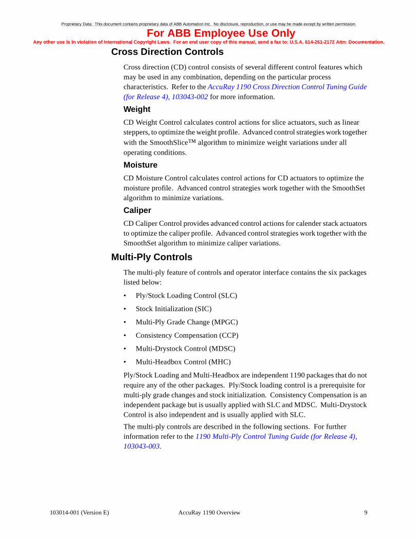
Display Layout
Figure 2-1 shows the basic layout of a display. Almost every display in your system has the major parts indicated below.
Figure 2-1 Basic Display Layout
Operating Procedures 103014-001 (Version E)
Proprietary Data: This document contains proprietary data of ABB Automation Inc. No disclosure, reproduction, or use may be made except by written permission.
For ABB Employee Use OnlyAny other use is in violatio ion.
103014-001 (Vers
n of International Copyright Laws. For an end user copy of this manual, send a fax to: U.S.A. 614-261-2172 Attn: Documentat
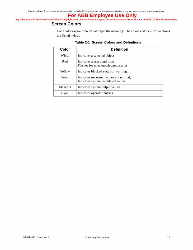
Screen Colors
Each color on your screen has a specific meaning. The colors and their explanations are listed below.
Table 2-1 Screen Colors and Definitions
Color Definition
White Indicates a selected object
Red Indicates alarm conditions; Flashes for unacknowledged alarms
Yellow Indicates blocked status or warning
Green Indicates measured values are normal;Indicates system calculated values
Magenta Indicates system output values
Cyan Indicates operator entries
15Operating Proceduresion E)

Proprietary Data: This document contains proprietary data of ABB Automation Inc. No disclosure, reproduction, or use may be made except by written permission.
For ABB Employee Use OnlyAny other use is in violatio ion.
16
n of International Copyright Laws. For an end user copy of this manual, send a fax to: U.S.A. 614-261-2172 Attn: Documentat
Symbol CodesDifferent symbols are used in screen displays to indicate the status of process signals and objects. The most common symbols are shown in Table 2-2. Table 2-2 Description of the Most Common Screen Symbols
Symbol Description
F Process fault (alarm)
B Blocked (input, output, alarm or event handling)
E Event blocked
Q Signal error
A Auto control to operator setpoint
M Manual control
MFd Forced manual control
Bal Balancing
L Local control
R Remote control
S Standby
U Unavailable (interlocked)
E1 - E3 Auto control to external reference
O Out of service
■ / ❒ Digital status: ON/OFF
MV Measured value
SP Setpoint (required value)
ACT Actuator Value
OUT Output signal
FF Feed forward
DEV Deviation
RAT Ratio
↑ / ↓ Incr/Decr Increasing/decreasing measured value
OP Actuator opens when the output signal increases
CL Actuator closes when the output signal decreases
H2/L2 Upper/lower alarm limit
H1/L1 Upper/lower warning limit
Adaption on The continuous self-tuning of the adaptive controller is in service
BS Back up station active
BSMan Back up station in manual mode
BSLoc Back up station supplies the setpoint
Operating Procedures 103014-001 (Version E)

Proprietary Data: This document contains proprietary data of ABB Automation Inc. No disclosure, reproduction, or use may be made except by written permission.
For ABB Employee Use OnlyAny other use is in violatio ion.
103014-001 (Vers
n of International Copyright Laws. For an end user copy of this manual, send a fax to: U.S.A. 614-261-2172 Attn: Documentat
Symbols Specific to the AccuRay 1190 Advant
There are some symbols that are specific to the AccuRay 1190 Advant system. They indicate frame status, control status, and operator action. If the value is blue, it is either a setpoint or an entered value. If the value is green, it is a measured or calculated value. A yellow X means the function is interlocked.
Frame Status
Status Indicator
Condition Possible Meanings
Green Filled Set; 1
Green Empty Reset; 0
Red Filled Warning or alarm
Red Blinking Unacknowledged warning or alarm
Yellow Empty Interlock
Operator Action
The diamond is used by operators to turn some specific controls on and off, to indicate participation of an actuator or feedforward control within a control strategy, and to select the participation of level 2 control in a level 3 strategy.
Condition Possible Meanings
Green Empty off; operator cannot select or change
Green Filled on, operator cannot select or change
Blue Empty off; operator can select and change
Blue Filled on; operator can select and change
Yellow Empty blocked
Red Empty off; disturbance mode
Green = scan; red = alarm
Green = standardization; red = alarm
Green = single point; red = alarm
Yellow = local or sheet break; red = alarm
17Operating Proceduresion E)

Proprietary Data: This document contains proprietary data of ABB Automation Inc. No disclosure, reproduction, or use may be made except by written permission.
For ABB Employee Use OnlyAny other use is in violatio ion.
18
n of International Copyright Laws. For an end user copy of this manual, send a fax to: U.S.A. 614-261-2172 Attn: Documentat
Display Links
Display links can be in the following forms:
• Programmable D-Keys
• Display Link Icons
• Assignable Keys
Programmable D-Keys
Access to other displays is available on each display by using the keys numbered D1 though D10. Display names/titles are shown in a D-key link at the bottom of the display. Press the appropriate D-key to go to that display.
Display Link Icons
The display link icon is used often throughout the display configuration. These display link icons appear in the graphic presentation on some displays to show a link to another display. This type of link can also be used to link displays to trend displays.
Assignable Keys
The Advant Operator Station Keyboard has a set of keys located on the lower left portion of the keyboard which are dedicated display links. They are numbered 1-20 and may be used twice by means of the shift key. Any displays that the customer selects can be assigned to these keys. Certain displays are already tied to other keys on the keyboard. See “Using the Keys” on page 20, for a detailed description of the keyboard.
Operating Procedures 103014-001 (Version E)

Proprietary Data: This document contains proprietary data of ABB Automation Inc. No disclosure, reproduction, or use may be made except by written permission.
For ABB Employee Use OnlyAny other use is in violatio ion.
103014-001 (Vers
A
n of International Copyright Laws. For an end user copy of this manual, send a fax to: U.S.A. 614-261-2172 Attn: Documentat
Controlling the CursorAll video displays have display links that match the dynamic keys (D-keys) on the keyboard and areas for data entry called data fields. You select these items by using the cursor. Your system can have any of the cursor controls listed below.
Trackball
Figure 2-2 Trackball
When you use a trackball, the cursor moves in the same direction you roll the ball. The buttons have the same functions as the corresponding fixed keys on the keyboard. The two select buttons make the trackball convenient for both right- and left-handed operators.
Mouse
Figure 2-3 Mouse
When you use a mouse, move the mouse in the direction you wish the cursor to move. The mouse will only work while on the mouse pad. All three buttons acts as a select key when on the 1190 displays.
Trackball, Basic Version Trackball, Enhanced Version
Send
Select
cknowledge
Select
Send
Select
Acknowledge
Select
Off OnAnalog Control
19Operating Proceduresion E)

Proprietary Data: This document contains proprietary data of ABB Automation Inc. No disclosure, reproduction, or use may be made except by written permission.
For ABB Employee Use OnlyAny other use is in violatio ion.
20
n of International Copyright Laws. For an end user copy of this manual, send a fax to: U.S.A. 614-261-2172 Attn: Documentat
Using the KeysIn addition to the special keys listed below the operator keyboard also has a numeric keypad and a standard “qwerty” keypad. There is also a set of keys in the upper right half of the keyboard used for building displays. The operator does not need to use these keys; therefore, they are not detailed below.
Note: Keys with a black triangle in the lower left corner have a secondfunction when the shift key is pressed simultaneously.
Operator Station Keys
Press to call up a menu containing the display libraries. After you have selected a library, all installed displays within the library are listed.
Display Menu
These keys are used for AdvaCommand® software options Status List.
Status List
Status List
Menu
Press this key to dislplay the alarm list. You can page through the entire list. The last 500 alarms are listed.
Alarm
Press this key to display the last page of the event list. You can pagethrough the entire list. The last 1000 events are listed.
Event List
System Status presents the status of the I/O boards, peripheral devices and communication links. Use to monitor and troubleshoot the system.
System Status
System List presents system alarms within the system. Used to monitor and troubleshoot the system.
SystemList
Press System Config to call up a menu from which you can start configuration and maintenance functions.
System Config
?Press to recall any help displays associated with the base display. The help display is always an overlap display.
Hardcopy Key. Press this key to obtain a color printout of the screen.
F1 F1-F8 are function keys for use with external applications.
D1
D1-D10 represent a dialog and show all possible actions the operator can choose for the selected object or display. These keys correspond to the ten buttons at the bottom of the screen.
Operating Procedures 103014-001 (Version E)

Proprietary Data: This document contains proprietary data of ABB Automation Inc. No disclosure, reproduction, or use may be made except by written permission.
For ABB Employee Use OnlyAny other use is in violatio ion.
103014-001 (Vers
n of International Copyright Laws. For an end user copy of this manual, send a fax to: U.S.A. 614-261-2172 Attn: Documentat
11-20 are direct selection keys. They can be used to call up displays, dialogues, or external applications. Each key can be used twice by means of the shift key.
To call up a base display, press the Display Request key; then type the display name. Press Shift and Display Request simultaneously to call up as an overlap display.
Display Req
To select an object, press the Object Request key; then type the object name.
Object Req
Select Key. Use this key to select a process object for control or to select displays from lists or menus. If you press the shift and select key simultaneously, you will get the object close-up without dialog.
Object
Object Display Key. This key calls up the object display which contains all available information for the selected process object. To pull up the object display as an overlap, press the Object and Shift keys simultaneously.
Trend Display Key. This key calls up the trend display for the selected process object. This function requires the object to be logged. To pull up the trend display as an overlap, press the Trend and Shift keys simultaneously.
Acknowledge Alarm Key. You acknowledge an alarm by positioning the cursor on the object name or symbol and pressing the acknowledge key.
Silence Alarm Key. Press to silence an audible alarm in the keyboard or an external audible alarm.
Dialog Takes you to subordinate dialogs.
Dialog Takes the dynamic function keys (D-key) back to their original dialog.
To cancel a selection, press Dialog Exit. This will free the object so it can be selected by another operator.
Dialog Exit
Press this key to bring the cursor to the dialog field. This key is used for special applications.
Dialog Entry
To call up the object display for the previously selected object, press this key.
Prev Object
Off. Press this key to turn valves, switches, motors, pumps, etc. off.
On. Press this key to turn valves, switches, motors, pumps, etc. on.
21Operating Proceduresion E)
Proprietary Data: This document contains proprietary data of ABB Automation Inc. No disclosure, reproduction, or use may be made except by written permission.
For ABB Employee Use OnlyAny other use is in violatio ion.
22
n of International Copyright Laws. For an end user copy of this manual, send a fax to: U.S.A. 614-261-2172 Attn: Documentat
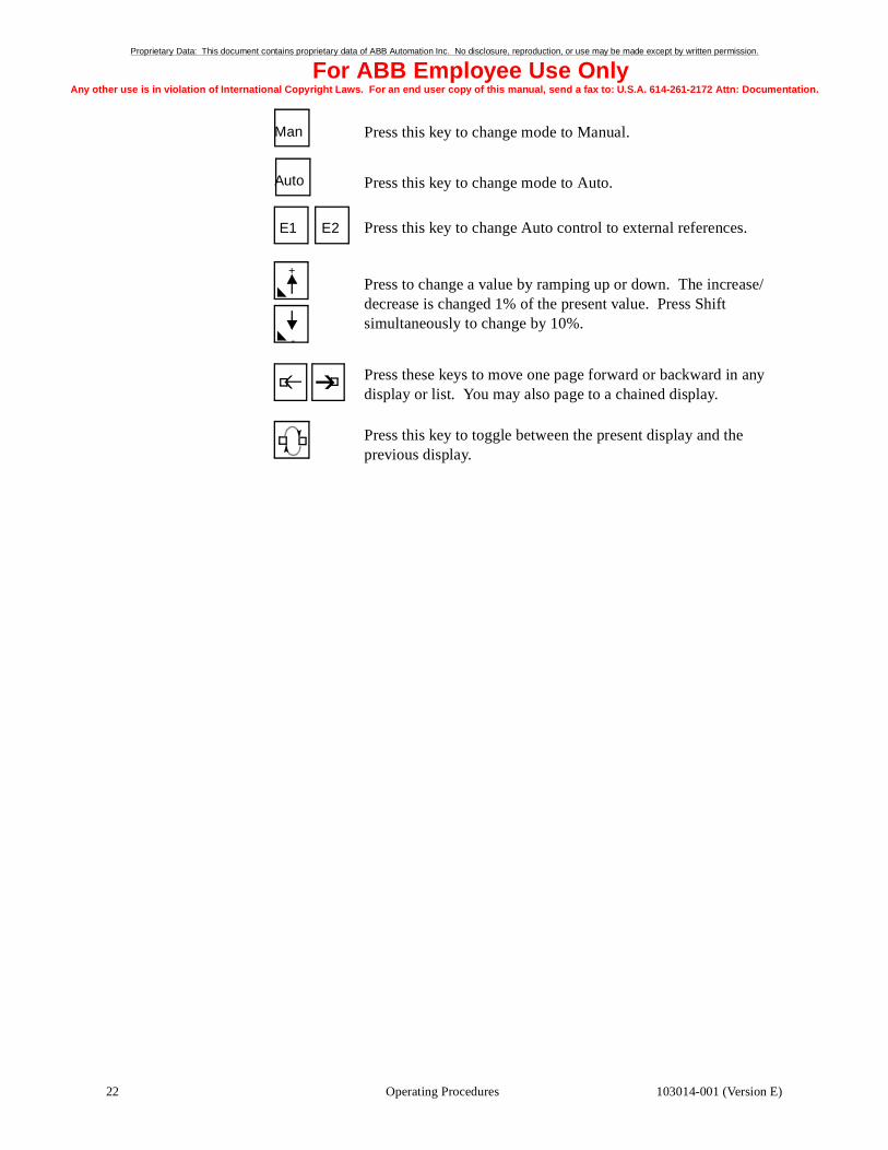
Man Press this key to change mode to Manual.
Auto Press this key to change mode to Auto.
E1 E2 Press this key to change Auto control to external references.
+
-
Press to change a value by ramping up or down. The increase/decrease is changed 1% of the present value. Press Shift simultaneously to change by 10%.
Press these keys to move one page forward or backward in any display or list. You may also page to a chained display.
Press this key to toggle between the present display and the previous display.
Operating Procedures 103014-001 (Version E)

Proprietary Data: This document contains proprietary data of ABB Automation Inc. No disclosure, reproduction, or use may be made except by written permission.
For ABB Employee Use OnlyAny other use is in violatio ion.
103014-001 (Vers
n of International Copyright Laws. For an end user copy of this manual, send a fax to: U.S.A. 614-261-2172 Attn: Documentat
Selecting ItemsDuring daily operations, you will need to select video displays and objects, and you will need to use the direct selection keys on the keyboard. The following section explains how to perform the various selection functions on the AccuRay 1190 Advant station.
Selecting Video Displays
You can select a video display four ways:
• Select a display link.
• Enter the video display identifier.
• Select the display on the Display Menu.
• Use direct selection keys
See Chapter 3 for detailed information on specific basic video displays. For detailed information on feature specific displays, see the appropriate feature specific operator manua, as listed in the Preface of this manual.
Select Display Links
One way to select a video display is to use a display link. Display link selections are the D1 through D10 boxes located across the bottom of your screen. Display names/titles are shown in the D-key links at the bottom of the display. Select the D-key on the bottom of the display or press the corresponding D-key on the keyboard. Figure 2-4 shows an example of the D-keys on the display. For example, in the figure below you could press D1 on the keyboard to select the System Overview display. You could also select D1 on the screen by placing the cursor over it and pressing Select.
Another type of display link is shown in Figure 2-5 on page 23. Selecting this icon will call up a new, related display.
Figure 2-4 D-Keys on the Screen
Figure 2-5 Display Link
23Operating Proceduresion E)

Proprietary Data: This document contains proprietary data of ABB Automation Inc. No disclosure, reproduction, or use may be made except by written permission.
For ABB Employee Use OnlyAny other use is in violatio ion.
24
n of International Copyright Laws. For an end user copy of this manual, send a fax to: U.S.A. 614-261-2172 Attn: Documentat
Enter Video Display Identifier
A second way to select a video display is to enter the display identifier.
1. Press the Display Request key on the keyboard.
2. Enter the video display identifier. If you do not know the video display identifier, see "Select from the Display Menu".
3. Press the Send key.
If you need to make a correction in your entry, or do not want to select a display at this time, press Dialog Exit.
Select from the Display Menu
Another way to select a video display is to select it from the Display Menu. If you do not know the identifier of the video display you want to select and it is not listed as a display link, you can look up the display on the Display Menu. The Display Menu provides a listing of all video displays and their identifiers. Follow the steps below to select a video display from the Display Menu.
1. Press Display Menu.
2. If the video display you want to view is not listed on the Display Menu that appears on your screen, either slide the window down to view additional displays or select another directory from the left column. A new list of displays will appear. Continue until you find the desired display. Figure 2-6 on page 26 shows an example of the Display Menu.
3. Place the cursor on the display you want to select.
4. Press the Select key.
Use Direct Selection Keys
Selecting a display directly means that you only have to press one key to call up the display. You can select the following displays directly:
• Display Menu - The display will list all process displays for which your system is configured. To select a display, place the cursor over the desired object, and press select. See Figure 2-6 on page 26.
• System List - The System List shows all system messages that occur. The information shown includes a brief message, description with net and node number, and the date and time of the occurrence. You can acknowledge these messages the same way as you acknowledge alarms. See “Acknowledging Alarms” on page 32. See Figure 2-7 on page 27.
• Event List - This display shows all the events occurring in the control system. The information shown includes the event object name, a description of the event, and the date and time of the occurrence. See Figure 2-9 on page 29.
Operating Procedures 103014-001 (Version E)

Proprietary Data: This document contains proprietary data of ABB Automation Inc. No disclosure, reproduction, or use may be made except by written permission.
For ABB Employee Use OnlyAny other use is in violatio ion.
103014-001 (Vers
n of International Copyright Laws. For an end user copy of this manual, send a fax to: U.S.A. 614-261-2172 Attn: Documentat
• Alarm List - This display lists all of the alarm occurrences with the newest alarm listed at the top of the page. The information shown includes the alarm code/message, a brief description, and the date and time of the occurrence. An R before the alarm denotes a repeated alarm. You can acknowledge the alarms as described on page 32. See Figure 2-8 on page 28.
• Status List - The Status List is a list of process (or calculated) signals and objects, satisfying a user-defined search. The criteria for inclusion in the list are specified by the user. The criteria may include one or several object types, part of an object name, the value of up to four arbitrary properties, the node number, the process section, and the object class. The results of each search are listed in the large block area in the middle of the display. Each search configuration can be saved and shown on the Status List Menu.
• Status List Menu - The Status List Menu shows all search configurations that were saved. You can activate a search by selecting the Active square of the desired Status List. The search will be run and the results displayed.
You select the list or menu you want by pressing the appropriate key on the keyboard. For example, to view the event list, press the Event List key. You may also recall specific displays by pressing the assignable keys 1-20. Press the appropriate number to recall the assigned display.
25Operating Proceduresion E)

Proprietary Data: This document contains proprietary data of ABB Automation Inc. No disclosure, reproduction, or use may be made except by written permission.
For ABB Employee Use OnlyAny other use is in violatio ion.
26
n of International Copyright Laws. For an end user copy of this manual, send a fax to: U.S.A. 614-261-2172 Attn: Documentat
Figure 2-6 Display Menu Example
Operating Procedures 103014-001 (Version E)

Proprietary Data: This document contains proprietary data of ABB Automation Inc. No disclosure, reproduction, or use may be made except by written permission.
For ABB Employee Use OnlyAny other use is in violatio ion.
103014-001 (Vers
n of International Copyright Laws. For an end user copy of this manual, send a fax to: U.S.A. 614-261-2172 Attn: Documentat
Figure 2-7 System List
27Operating Proceduresion E)

Proprietary Data: This document contains proprietary data of ABB Automation Inc. No disclosure, reproduction, or use may be made except by written permission.
For ABB Employee Use OnlyAny other use is in violatio ion.
28
n of International Copyright Laws. For an end user copy of this manual, send a fax to: U.S.A. 614-261-2172 Attn: Documentat
Figure 2-8 Alarm List
Operating Procedures 103014-001 (Version E)

Proprietary Data: This document contains proprietary data of ABB Automation Inc. No disclosure, reproduction, or use may be made except by written permission.
For ABB Employee Use OnlyAny other use is in violatio ion.
103014-001 (Vers
n of International Copyright Laws. For an end user copy of this manual, send a fax to: U.S.A. 614-261-2172 Attn: Documentat
Figure 2-9 Event List
Selecting Objects
An object is a field on your screen that you can select, such as a setpoint value. To change a characteristic of an object, you must first select the object. You can select both text and graphics. Most selectable objects are blue. Once you have selected an object, it appears white. Follow the steps below to select an object.
1. Select the video display you want. See “Selecting Video Displays” on page 23.
2. Position the cursor over the field you want to select. Blue corners will appear around the object. If the blue corners do not appear, the object may still be selectable.
3. Press the Select key. The dialog for that object will appear.
4. For extended object information, press the Object Display key. For trend information, press the Object Trend key. To return to the main display, press the Previous Display key.
29Operating Proceduresion E)

Proprietary Data: This document contains proprietary data of ABB Automation Inc. No disclosure, reproduction, or use may be made except by written permission.
For ABB Employee Use OnlyAny other use is in violatio ion.
30
n of International Copyright Laws. For an end user copy of this manual, send a fax to: U.S.A. 614-261-2172 Attn: Documentat
Changing the Setpoint and ModeChanging the Setpoint
When you are in the automatic or manual mode (based on the element type), you can change the control setpoint. Follow the steps below to change the setpoint.
1. Select the object of which you want to change the setpoint.
2. Press the D7 (Setpoint).
3. Enter the new setpoint.
4. Press Send.
Changing the Mode
You can change the control mode to any of the following:
• Manual (M) - controlled by the operator
• Automatic (A) - controlled to the operator-entered setpoint
• External (E) - controlled to an external setpoint
1. Select the control of which you wish to change the mode. After you select the item, the D-keys across the bottom of the display will change.
2. Press D10 (Keyboard...).
3. Change the mode according to the instructions below:
If you want to change the control to manual, either press the MAN key or D2 (MAN).
If you want to change the control to automatic, either press the AUTO key or D3 (AUTO).
If you want to change the control to external mode, either press the E1 key or D4 (E1). In order for the Level 2 control to go to Auto, the Level 1 control must be in E1 or Auto.
Level one controls include actuator level loops. Higher level control loops are supervisory loops to the level one controls (e.g. scan level controls, coordinated speed change, and auto grade change.). The control mode transitions are shown in Table 2-3 and Table 2-4. The tables show the reactions of the level 2 and the level 1 control modes to actions performed on the level 1 and the level 2 control modes, respectively.
Operating Procedures 103014-001 (Version E)

Proprietary Data: This document contains proprietary data of ABB Automation Inc. No disclosure, reproduction, or use may be made except by written permission.
For ABB Employee Use OnlyAny other use is in violatio ion.
103014-001 (Vers
n of International Copyright Laws. For an end user copy of this manual, send a fax to: U.S.A. 614-261-2172 Attn: Documentat
Table 2-3 Reaction of Level 2 to Level 1 Mode Changes
Table 2-4 Reaction of Level 1 to Level 2 Mode Changes
Original Level 1 Mode
Level 1 Mode
changed to:
Original Level 2 Mode
Level 2 Mode after
Level 1 Mode
changed
Then the Feedforward
Bal Manual Bal Bal cannot be sent to lvl 1
Manual Auto Bal Manual cannot be sent to lvl 1
Auto E1 Manual Manual can be sent to lvl 1
Manual E1 Bal Manual can be sent to lvl 1
E1 Manualor Bal
Auto or Manual
Bal cannot be sent to lvl 1
E1 Auto Auto or Manual
Manual cannot be sent to lvl 1
Auto Manualor Bal
Manual Bal cannot be sent to lvl 1
Manual bal Bal Bal cannot be sent to lvl 1
Original Level 2 Mode
Level 2 Mode
changed to:
Original Level 1 Mode
Level 1 Mode after
Level 2 Mode
changed
Then the Feedforward
Manual Auto Auto E1 can be sent to level 1
Auto Manual E1 E1 can be sent to level 1
31Operating Proceduresion E)

Proprietary Data: This document contains proprietary data of ABB Automation Inc. No disclosure, reproduction, or use may be made except by written permission.
For ABB Employee Use OnlyAny other use is in violatio ion.
32
n of International Copyright Laws. For an end user copy of this manual, send a fax to: U.S.A. 614-261-2172 Attn: Documentat
Acknowledging AlarmsYou can acknowledge alarms from the following display types:
• Process Alarm List
• Process Displays
• Object Displays
Acknowledging Alarms from the Process Alarm List
To acknowledge alarms from the process alarm list, follow the steps below.
Note: When you acknowledge an alarm, the object with the alarmcondition stays red until you eliminate (correct) the alarm condition.When the alarm condition has been corrected, the alarm disappearsfrom the alarm list and the object changes from red to its previouscolor.
1. Press the Alarm List key. The alarm list scrolls upwards (10 lines at a time) so that new alarms can appear on the screen.
2. Press D5 (Stop Update) to freeze the alarm list. The list will be outlined in yellow. You must press this key before you can select an alarm line with the cursor. The last page of alarms is frozen in the display. Unacknowledged alarms are marked with a flashing red asterisk (*).
3. Acknowledge the alarm either of the following two ways:
• Acknowledge the alarms line by line:
a. Move the cursor to the line to be acknowledged.
b. Press Select.
c. Press the Acknowledge Alarm key. The flashing red asterisk (*) will disappear.
• Acknowledge every unacknowledged alarm on the page:
a. Press D4 (Acknowledge Page).
b. When all the alarms are acknowledged, press D10 (Continue Update).
Acknowledging Alarms from Process and Object Displays
Follow the steps below to acknowledge alarms from process and object displays.
1. Place the cursor where indicated from the list below.
Overview and group displays: On the name of the object
Process diagram displays: On the object symbol or the value
Object displays: On the object
2. Press Acknowledge Alarm. The alarm will stop flashing.
Operating Procedures 103014-001 (Version E)

Proprietary Data: This document contains proprietary data of ABB Automation Inc. No disclosure, reproduction, or use may be made except by written permission.
For ABB Employee Use OnlyAny other use is in violatio ion.
103014-001 (Vers
n of International Copyright Laws. For an end user copy of this manual, send a fax to: U.S.A. 614-261-2172 Attn: Documentat
Receiving Extended Alarm Information
You cannot acknowledge alarms directly from the alarm line at the top of a display, but you can receive extended information about the alarm from the alarm line by following the steps below.
1. Place the cursor on the alarm.
2. Press Select. Information and dialog keys will appear.
3. If further information is required, place the cursor over the name of the object and press the Object Display key.
33Operating Proceduresion E)

Proprietary Data: This document contains proprietary data of ABB Automation Inc. No disclosure, reproduction, or use may be made except by written permission.
For ABB Employee Use OnlyAny other use is in violatio ion.
34
n of International Copyright Laws. For an end user copy of this manual, send a fax to: U.S.A. 614-261-2172 Attn: Documentat
Printing Video DisplaysDuring system operation, you can request a printout of any video display. To request a printout, follow the steps below.
1. Make sure the video display you want to print is on the screen. See “Selecting Video Displays” on page 23.
2. Press the Hardcopy key for a color printout.
Operating Procedures 103014-001 (Version E)

Proprietary Data: This document contains proprietary data of ABB Automation Inc. No disclosure, reproduction, or use may be made except by written permission.
For ABB Employee Use OnlyAny other use is in violatio ion.
103014-001 (Vers
n of International Copyright Laws. For an end user copy of this manual, send a fax to: U.S.A. 614-261-2172 Attn: Documentat
Restarting the SystemUse the following procedure when you need to restart the system for any reason.
1. Start up the Advant Workstation and the MasterPiece 280 using the procedures in the appropriate Master documentation.
2. Select the System Overview video display.
3. Select the number next to the words New Grade.
4. Enter the correct product number.
Note: If the correct product number is already entered, first enter adifferent product number then approximately fifteen seconds laterenter the correct product number.
5. Perform a Manual Grade Change to activate the new grade.
6. Enter the correct reel number.
7. Enter the correct reel trim.
8. Place the measurement heads on sheet at the frame.
9. After the first standardize is complete, request scan.
35Operating Proceduresion E)

Blank Page

Proprietary Data: This document contains proprietary data of ABB Automation Inc. No disclosure, reproduction, or use may be made except by written permission.
For ABB Employee Use OnlyAny other use is in violatio ion.
103014-001 (Vers
n of International Copyright Laws. For an end user copy of this manual, send a fax to: U.S.A. 614-261-2172 Attn: Documentat
3Base System Displays
Chapter Three provides examples, functions, and usage of the base system displays.
This chapter contains the following major sections:
Section............................................................................................... Page
System Overview ........................................................................................... 38Frame Overview ............................................................................................ 39Paper Machine Overview .............................................................................. 42Headbox Control Summary ........................................................................... 45Measurement Overview ................................................................................. 46Measurement Status ...................................................................................... 48Machine Direction Control ............................................................................ 50Production Summary ..................................................................................... 53Speed Control Summary ............................................................................... 54Auto Grade Change Summary ...................................................................... 60Grade Grouping ............................................................................................. 66Grade Data ..................................................................................................... 67Roll Set Summary ......................................................................................... 73Composite Profile Displays ........................................................................... 74
37Base System Displaysion E)

Proprietary Data: This document contains proprietary data of ABB Automation Inc. No disclosure, reproduction, or use may be made except by written permission.
For ABB Employee Use OnlyAny other use is in violatio ion.
38
E
D
A
n of International Copyright Laws. For an end user copy of this manual, send a fax to: U.S.A. 614-261-2172 Attn: Documentat
System OverviewThe System Overview display is intended to provide the majority of the information you will need. See Figure 3-1. The frame section shows frame modes and allows global control of frames. The production section shows reel, grade, day, and shift production in tons. The control section shows the measured value, setpoint, and status of your MD controls. The grade change area allows you to select and change grades. The profile section displays any two profiles you choose. This area functions the same as on the Composite Profile display.
For further information about these sections, see the associated display details. The circled capital letters in Figure 3-1 correspond to the list below:
A. “Frame Overview” on page 39.
B. “Production Summary” on page 53.
C. “Machine Direction Control” on page 50.
D. “Auto Grade Change Summary” on page 60.
E. “Composite Profile Displays” on page 74.
Figure 3-1 System Overview Display
CB
Base System Displays 103014-001 (Version E)

Proprietary Data: This document contains proprietary data of ABB Automation Inc. No disclosure, reproduction, or use may be made except by written permission.
For ABB Employee Use OnlyAny other use is in violatio ion.
103014-001 (Vers
n of International Copyright Laws. For an end user copy of this manual, send a fax to: U.S.A. 614-261-2172 Attn: Documentat
Frame OverviewThe Frame Overview display (Figure 3-2) shows the frame mode, head position, and alerts the operator to various alarms and service needs. Off-sheet, scan, single point, and standardize appear for global and individual frames. Auto edge-of-sheet, independent, local, sheet-break, current head position, single point position, comm failure, frame service check, electric service check, measurement service check, over temp, safety interrupt, IR cooling flow, auto edge alarm, scan limit alarm, and sensor alarm are shown for individual frames.
Note: Normally all frames are in global mode, and frame control isperformed using the global frame object or the frame push buttonsin the fixed display area.
Figure 3-2 Frame Overview Display
39Base System Displaysion E)

Proprietary Data: This document contains proprietary data of ABB Automation Inc. No disclosure, reproduction, or use may be made except by written permission.
For ABB Employee Use OnlyAny other use is in violatio ion.
40
n of International Copyright Laws. For an end user copy of this manual, send a fax to: U.S.A. 614-261-2172 Attn: Documentat
Changing Measurement Modes
The two measurement modes available for the frame are single point mode and scanning mode. When in single point mode the frame moves the measurement sensors to a point on the process. The sensor package stays at that point until you initiate a change. In scanning mode, the frame moves the measurement sensors back and forth across the process at a constant rate. To collect profile information and use CD control, the frames must be in scanning mode.
Selecting Single Point Position
The single point mode allows the scanning platform to drive to a predetermined position and remain there. You can position the sensor package over any position on the process with the single point measurement platform controls. The sensor package remains at the position you requested until you select off-sheet or scan.
1. Select the frame object. You may perform this procedure on an individual frame in independent mode or on all frams in global control.
2. Press D7 (Single Point Position).
3. Determined the desired sensor position for single point. The value may be between 0 (home edge) and 1000 (far edge).
4. Enter the determined value.
5. Press Send.
To remove the frame from single point mode, select the appropriate frame object (or global frame object) and choose scan or off-sheet.
Sample Check Overlap Display
To view the Sample Check Compensation display, select the display link with the S in it. The Sample Check Compensation display will appear as an overlap to the Frame Overview.
Figure 3-3 Sample Check Compensation Overlap Display
Base System Displays 103014-001 (Version E)

Proprietary Data: This document contains proprietary data of ABB Automation Inc. No disclosure, reproduction, or use may be made except by written permission.
For ABB Employee Use OnlyAny other use is in violatio ion.
103014-001 (Vers
n of International Copyright Laws. For an end user copy of this manual, send a fax to: U.S.A. 614-261-2172 Attn: Documentat
Sample Check Mode
A value of 0, 1, 2, or 3 describes the sample check mode. They are as follows:
0 = Not in Sample Check Mode
1 = Sensor Verification(requires manually entered compensation values)
2 = Measure(uses normal compensation sources)
3 = Stability (uses product code compensation values)
4 = Use Internal Sample(for weight and ash only; other sensors treat as mode 1)
5 = Special mode for off-line target setup for Smart Color Sensor. Refer to the AccuRay 1190 Smart Color Measurement Manual, 103004-001.
Compensation Values
Basis weight, moisture, ash, and temperature compensation values can be entered here. These values are used for sensor verification.
Ash Flag
Setting for the ash sensor flag which crosses the x-ray path. To insert the flag, enter 1. To remove the flag, enter 0.
41Base System Displaysion E)

Proprietary Data: This document contains proprietary data of ABB Automation Inc. No disclosure, reproduction, or use may be made except by written permission.
For ABB Employee Use OnlyAny other use is in violatio ion.
42
n of International Copyright Laws. For an end user copy of this manual, send a fax to: U.S.A. 614-261-2172 Attn: Documentat
Paper Machine OverviewIn addition to the Paper Machine Overview display showing parts of several other displays, it also shows a graphical representation of the paper machine. Various setpoints, measured values, and status are shown. This display is configured in this manner to avoid having to switch back and forth between displays. However, for more detailed information on conditions and alarms, you need to see either the object display or the display from which the area in question originated. The circled capital letters in Figure 3-4 correspond to the list below:
A. “Auto Grade Change Summary” on page 60.
B. “Speed Control Summary” on page 54.
C. “Machine Direction Control” on page 50.
Figure 3-4 Paper Machine Overview Display
A B C
Base System Displays 103014-001 (Version E)

Proprietary Data: This document contains proprietary data of ABB Automation Inc. No disclosure, reproduction, or use may be made except by written permission.
For ABB Employee Use OnlyAny other use is in violatio ion.
103014-001 (Vers
n of International Copyright Laws. For an end user copy of this manual, send a fax to: U.S.A. 614-261-2172 Attn: Documentat
From the Paper Machine Overview you will have all the information available about your process, and access to the following:
• Input signals from the process
• Level 1 control loops
• Machine direction control loops
• Auto grade change status
• Speed control status
• Frame status
From the Paper Machine Overview display you can do the following:
• Change all the level 1 controls and machine direction controls
• Initiate coordinated speed changes and grade changes
• Select scanning operations, such as scan and off-sheet
The Paper Machine Overview display also provides you with the status of each function in your process. If there is a problem with a function, it will be indicated on the display. To investigate a problem, use the object display for that function, or go to that particular display. For example, you can go to the Auto Grade Change Summary display to find out why auto grade change is not ready for operation, or you can select the object display for the frame to find out why the frame is alarming.
Interpreting Control Loops
Control loops are shown with the loop-measured value in green, and the controller mode indicated with a green character above the loop-measured value. Some level 2 controllers have their setpoint (blue) between the measured value and the controller mode. The controller modes are as follows:
• Bal (Balance): the loop output signal is NOT controlled from the controller
• M (Manual): the loop output signal is controlled by the operator-entered manual output
• A (Auto): the loop output signal is calculated from the loop-measured value and the setpoint entered by the operator
• E1 (External reference 1): the loop output signal is calculated from the loop measured value and a setpoint received from another controller
• E2 (External reference 2): same as E1, but using a second external setpoint
Next to the controller mode a yellow X may appear. This condition indicates an interlocked or suspended loop. For example, the machine direction controls will suspend during a sheet-break.
When you select a controller on the display, the small object close-up window will pop up in the lower right corner of the display showing more information about the loop. To get the full information about the loop, press the Object Display key.
43Base System Displaysion E)

Proprietary Data: This document contains proprietary data of ABB Automation Inc. No disclosure, reproduction, or use may be made except by written permission.
For ABB Employee Use OnlyAny other use is in violatio ion.
44
n of International Copyright Laws. For an end user copy of this manual, send a fax to: U.S.A. 614-261-2172 Attn: Documentat
Determining Frame Status
The frame status symbol indicates scanning frame modes. The frame status symbol is presented on the graphical drawing of the frame in the process. Next to the status symbol is a character indicating from where the frame is controlled:
• L (Local): the frame push button panel operates the frame
• I (Individual): by selecting the individual frame symbols, you can operate the frame from the operator station
• G (Global): by selecting the global frame object, located in the fixed display area, you can operate all the frames set for global mode
When a frame status symbol is selected, the small object close-up window pops up in the lower right corner of the display. This window has more status information about the frame.
To get full information about the frame, press the Object Display key.
Dryer Ramping/Loading
For an example of the Dryer Ramping/Dryer Loading Overlap display see Figure 3-5
Figure 3-5 Dryer Ramping/Dryer Loading Overlap Display
Dryer Ramping
Ramps the dryers’ steam pressure down to a percentage or to a predetermined point when a sheet break occurs. This decrease prevents the heat from causing trouble when rethreading the sheet. When the sheet is again present, the dryer ramps the pressure up to the desired level. When the diamond is filled, ramping is enabled. When a sheet break occurs, you will see a ramp in progress.
Dryer Loading
This function enables the operator to control more than one dryer section. All dryer sections are connected to a reference section. Biases and ratios can be applied to the main section’s control steam pressure to obtain control settings for the remaining dryers. A bias is an offset from the main dryer setting, and a ratio is a ratio applied to the main dryer setting. A ratio of one would mean that the dryer would have the same control settings as the main dryer section.
Base System Displays 103014-001 (Version E)

Proprietary Data: This document contains proprietary data of ABB Automation Inc. No disclosure, reproduction, or use may be made except by written permission.
For ABB Employee Use OnlyAny other use is in violatio ion.
103014-001 (Vers
n of International Copyright Laws. For an end user copy of this manual, send a fax to: U.S.A. 614-261-2172 Attn: Documentat
Headbox Control SummaryThe Headbox Control Summary display allows you to access level 1 and 2 headbox controls and shows measured values of various headbox controls. You may change the setpoint and mode as described in “Changing the Setpoint” on page 30 and “Changing the Mode” on page 30.
Figure 3-6 Headbox Control Summary Display
You may access the following level 1 controls: slice, stream flow, headbox level, and stock flow.
You may access the following level 2 controls: rush/drag, dryline step change, headbox level, and reel basis weight.
The dryline may be moved upstream or downstream by the dryline step change. An integer value (positive or negative) may be entered as a fractional change to the dryline actuator.
45Base System Displaysion E)

Proprietary Data: This document contains proprietary data of ABB Automation Inc. No disclosure, reproduction, or use may be made except by written permission.
For ABB Employee Use OnlyAny other use is in violatio ion.
46
n of International Copyright Laws. For an end user copy of this manual, send a fax to: U.S.A. 614-261-2172 Attn: Documentat
Measurement OverviewThe Measurement Overview display gives object ID, validity, status, and maintenance information for each scanning measurement within the system. Any malfunction which causes the measurement to be invalid will cause the line for the affected measurement to be displayed in red and the general fault will be reported under the Status column. See Figure 3-7. For more detailed information concerning the malfunction, see the Measurement Status display.
Figure 3-7 Measurement Overview Display
Report Print On/Off
Selecting one of these buttons will enable printing of the indicated frame report when the event occurs. The button will appear depressed and the “P” will be green. During the printing the “P” will be flashing green. After printing the “P” will return to green indicating that report printing is still enabled. Selecting the button again will disable printing of the report.
Base System Displays 103014-001 (Version E)

Proprietary Data: This document contains proprietary data of ABB Automation Inc. No disclosure, reproduction, or use may be made except by written permission.
For ABB Employee Use OnlyAny other use is in violatio ion.
103014-001 (Vers
n of International Copyright Laws. For an end user copy of this manual, send a fax to: U.S.A. 614-261-2172 Attn: Documentat
Print History
Selecting one of the history print buttons enters a request to print the measurement history buffer containing the last twenty events. The button will appear depressed and the “P” will be green. When the request is being processed, the “P” will be flashing green. When processing is complete the button will return to the original raised condition with the “P” black. The request may be canceled by selecting the button again before it begins to flash.
Disable Profile Compositing
Selecting one of these buttons will disable profile compositing. The button will appear depressed and the “D” will be green. During this state, the composite profile display for the measurement will be unfiltered single scan measurement values. Compositing may be re-enabled by selecting the button again.
47Base System Displaysion E)

Proprietary Data: This document contains proprietary data of ABB Automation Inc. No disclosure, reproduction, or use may be made except by written permission.
For ABB Employee Use OnlyAny other use is in violatio ion.
48
n of International Copyright Laws. For an end user copy of this manual, send a fax to: U.S.A. 614-261-2172 Attn: Documentat
Measurement StatusThe Measurement Status display provides detailed information about the selected measurement. Current measurement values, grade code data, and results from the most recent standardize, calibrate sample, and sample check are presented. Calibration for PMM caliper and gloss and sensor off-line diagnostics mode may be changed from this display. See Figure 3-8.
Figure 3-8 Measurement Status Display
Measurement Selection
Selecting the M button will open the measurement selection menu window. You may select the measurement whose statistics you wish to view by using the following procedure:
1. Place the cursor over the desired measurement.
2. Press select.
3. Press OK.
Base System Displays 103014-001 (Version E)

Proprietary Data: This document contains proprietary data of ABB Automation Inc. No disclosure, reproduction, or use may be made except by written permission.
For ABB Employee Use OnlyAny other use is in violatio ion.
103014-001 (Vers
n of International Copyright Laws. For an end user copy of this manual, send a fax to: U.S.A. 614-261-2172 Attn: Documentat
Sensor Status
Time based data, scan average, composite average, and sensor status are displayed in this window.
Grade Data
Values for the active and preliminary grade codes are displayed here.
Standardize, Calibrate Sample, Sample Check
Results from the most recent occurrence of these functions are displayed in the bottom row of windows. Data is updated at the conclusion of each event.
Sensor Local Modes
Local diagnostic functions may be entered here. These functions are for off-line testing of the sensor. Do not use during on-line measurement.
Sensor Calibration Data
Sensor calibration data may be entered here for PMM caliper or gloss sensors. This area is inactive for any other frame type or sensor.
49Base System Displaysion E)

Proprietary Data: This document contains proprietary data of ABB Automation Inc. No disclosure, reproduction, or use may be made except by written permission.
For ABB Employee Use OnlyAny other use is in violatio ion.
50
n of International Copyright Laws. For an end user copy of this manual, send a fax to: U.S.A. 614-261-2172 Attn: Documentat
Machine Direction ControlThe Machine Direction (MD) Overview display provides access to the Machine Direction Controls listed below. See Figure 3-9.
Weight Control - compares the weight measurement to the weight target and determines a control action based on the difference. Adjustments are then made to the participating stock controllers. The weight control, based on configuration, requires a basis weight or conditioned weight target entry.
Moisture Controls - compares the moisture measurement to the target and determines a control action based on the difference. Corrections are made to the steam pressure controllers.
Opacity Control - compares the opacity measurement to the target and determines a control action based on the difference. Corrections are made to the Titanium Dioxide (TiO2) flow.
Ash Control - compares the ash measurement to the target and determines a control action based on the difference. Corrections are made to the Clay flow.
Rush/Drag - controls the difference between the speed of the stock coming out of the headbox and the wire speed.
Coordinated Speed Change - provides a smooth change of machine speed while maintaining weight, moisture, opacity, and ash targets.
Drystock Control - monitors the thick stock consistency and makes changes to the stock flow.
You can make changes to the control loop’s status and targets as well as the controller’s setpoints and modes.
Base System Displays 103014-001 (Version E)

Proprietary Data: This document contains proprietary data of ABB Automation Inc. No disclosure, reproduction, or use may be made except by written permission.
For ABB Employee Use OnlyAny other use is in violatio ion.
103014-001 (Vers
n of International Copyright Laws. For an end user copy of this manual, send a fax to: U.S.A. 614-261-2172 Attn: Documentat
Figure 3-9 Machine Direction Overview Display
Level 1 Controls
You can perform the following functions for level 1 controls:
• Change the setpoint (page 30)
• Change the control mode (page 30)
• Request communication with level 2 controls using external mode
• Change the manual output while in manual mode
Level 1 controls include stock flow, steam pressure 1 and 2, TiO2 flow, slice, speed
actuator, and clay flow.
51Base System Displaysion E)

Proprietary Data: This document contains proprietary data of ABB Automation Inc. No disclosure, reproduction, or use may be made except by written permission.
For ABB Employee Use OnlyAny other use is in violatio ion.
52
n of International Copyright Laws. For an end user copy of this manual, send a fax to: U.S.A. 614-261-2172 Attn: Documentat
Changing the Manual Output
You can change the manual output for level 1 controls only when the control is in manual mode. Follow the steps below.
1. Select the object of which you want to change the manual output.
2. Change the mode to manual according to the instructions in “Changing the Mode” on page 30.
3. If it is not already selected, press D6 (Out).
4. Enter the new manual output value.
This value should be -100% to +100% pulse output or 0% to 100% full value.
5. Press Send.
Level 2 Controls
You can perform the following functions for level 2 controls:
• Change the setpoint (page 30)
• Change the control mode (page 30)
• Turn Drystock on and off
Level 2 controls include basis weight reel, moisture size, moisture reel, opacity, jet/wire ratio, coordinated speed control, ash, and drystock.
Changing Drystock
If the level 2 dry stock control is available and in manual mode, you can turn it on and off. Follow the steps below to turn drystock on or off.
1. Select the diamond beside the drystock line on the screen. When the diamond is selected, it will be outlined in white.
2. Press D1 (ON) to turn the control on. Press D6 (OFF) to turn the control off. If the diamond is filled, drystock is on. If the diamond is not filled, drystock is off.
or
1. Select the drystock diamond.
2. Press the on or off key on the keyboard to turn the drystock on or off.
Process Overview
This section presents a graphical overview of your process. Various information is shown in its appropriate position along the process. These values may be manipulated as normal. For further information view the object display for the process information in question.
Base System Displays 103014-001 (Version E)

Proprietary Data: This document contains proprietary data of ABB Automation Inc. No disclosure, reproduction, or use may be made except by written permission.
For ABB Employee Use OnlyAny other use is in violatio ion.
103014-001 (Vers
n of International Copyright Laws. For an end user copy of this manual, send a fax to: U.S.A. 614-261-2172 Attn: Documentat
Production SummaryThe Production Summary display, Figure 3-10, provides a tabular display of production data. Production is summed for each scan during the shift. At the beginning of the new shift, the next column on the Production Summary display is continuously summed with new data. At the end of the third shift, the report (except for the grade data) is reset. Grade data is reset when the next grade change takes place. Reel data accumulates until a reel turn-up occurs, at which time the current accumulations reset and new reel data collection begins.
Figure 3-10 Production Summary Display
The data fields on the Production Summary Report are described below.
• Production: Amount of paper being made
• Thruput: Rate of production
• Average Speed: Average reel speed
• Run Time: Time when not in grade change or sheet break
• Lost Time: Sheet-break time minus sheet-break time during a grade change; no production accumulations
• Grade Change: Time spent in grade change from start to on grade
53Base System Displaysion E)

Proprietary Data: This document contains proprietary data of ABB Automation Inc. No disclosure, reproduction, or use may be made except by written permission.
For ABB Employee Use OnlyAny other use is in violatio ion.
54
n of International Copyright Laws. For an end user copy of this manual, send a fax to: U.S.A. 614-261-2172 Attn: Documentat
Speed Control SummaryYou can perform the following functions for the Coordinated Speed and Speed Optimization Controls:
• Change the Controller to Automatic (AUTO)
• Initiate the Speed Change
• Abort the Speed Change
• Use the Expert Speed Setpoint Handler
• Turn Speed Optimization On
• Interpret Alarms
See Figure 3-11 throughout the following sections. The top right portion of the Paper Machine Overview display (Figure 3-1 on page 38) represents Coordinated Speed.
Figure 3-11 Speed Control Summary Display
Base System Displays 103014-001 (Version E)

Proprietary Data: This document contains proprietary data of ABB Automation Inc. No disclosure, reproduction, or use may be made except by written permission.
For ABB Employee Use OnlyAny other use is in violatio ion.
103014-001 (Vers
n of International Copyright Laws. For an end user copy of this manual, send a fax to: U.S.A. 614-261-2172 Attn: Documentat
Changing the Controller to AUTO
Follow the steps below to place the coordinated speed controller into the AUTO mode on the Paper Machine Overview display or the Speed Control Summary display.
1. Place the speed control into manual mode.
2. When the coordinated speed controller (see Figure 3-11) indicates that it is currently in the MAN mode, select the Coord. Speed object (MSpd on the Paper Machine Overview display). Make sure the current speed setpoint is equal to the current level 1 speed setpoint before selecting the AUTO mode.
3. Press the AUTO key on the keyboard or press D10 (Keyboard...) then D3 (AUTO). This will also cause the machine speed to go to E1 mode. As soon as the coordinated speed controller is turned to AUTO, it will start ramping the speed to its setpoint.
If a yellow X appears beside the speed control mode, a suspend condition is occuring. This is caused by a required level 1 controller that is not in E1 or the product is off-grade.
If the coordinated speed controller indicates that it is in the BAL mode, this means that the level one speed controller is not in the AUTO mode and it is not available. You must then put the level one speed controller (found on the MD Control Overview display) in AUTO before you can turn the coordinated speed controller to AUTO.
Initiating a Speed Change
You can initiate a coordinated speed change when the coordinated speed controller is in the AUTO mode by following the steps below on the Paper Machine Overview display or the Speed Control Summary display.
1. Select the Coord. Speed setpoint value (MSpd on the Paper Machine Overview display).
2. Press D7 (SP).
3. Enter the new setpoint.
4. Press Send.
The controller will check for a deviation between the operator setpoint and the working setpoint. If there is an inequality, the working setpoint will ramp to the operator setpoint.
If the setpoint change is larger than a specified dead band, the controller will start to ramp the participating actuators and the speed’s working setpoint. The dead band is found as a parameter on the Speed Tuning display.
If the setpoint entry is outside the present setpoint limitations, the entry will be rejected, and the following system message will be displayed: Value out of range. Input ignored.
55Base System Displaysion E)

Proprietary Data: This document contains proprietary data of ABB Automation Inc. No disclosure, reproduction, or use may be made except by written permission.
For ABB Employee Use OnlyAny other use is in violatio ion.
56
n of International Copyright Laws. For an end user copy of this manual, send a fax to: U.S.A. 614-261-2172 Attn: Documentat
If Coord. Speed is put into auto and the setpoint is different than the level 1 setpoint, a speed change is initiated. If the difference between the operator setpoint and the current speed measurement is greater than the excessive error limit, the current level 1 speed setpoint will be used for the coordinated speed controller setpoint and an alarm will be issued.
The coordinated speed change will use the feedforwards indicated as required (diamond in “Level 1 Control” portion of display).
The state of the diamonds ia as follows:
Filled Diamond: This indicates that the level 1 actuator is required for coordinated speed change.
Empty Diamond: This indicates that the actuator is not required for coordinated speed change.
The status of each feedforward is indicated by the square next to the Required diamond. The status are as indicated below:
Filled Green Box: This indicates that the feedforward is enabled and the actuator is ready to participate in a coordinated speed change.
Filled Yellow Box: This indicates that the actuator used by the feedforward is participating, but is either setpoint or output limited. This indication appears only when coordinated speed control is in Auto.
Empty Green Box: This indicates that the feedforward is not enabled and the actuator is not participating in a coordinated speed change.
Empty Yellow Box: This indicates that the actuator is required to participate, but is not available for feedforward corrections. This will occur when the feedforward is enabled and the corresponding level 1 actuator is not in E1 and causes the coordinated speed controller to suspend.
Aborting a Speed Change
To abort a speed change, follow the steps below on the Paper Machine Overview display or the Speed Control Summary display. The abort will reset the ramp module of the speed change control and will terminate all actuator ramps.
1. Select the Coord. Speed Controller object (MSpd on the Paper Machine Overview display).
2. Press the MAN key or D10 (Keyboard...), then D2 (MAN). This will stop the actuator ramps.
The speed change will automatically abort if a delay in the control actions exceeds a preset time limit (the dead time overflow limit).
Base System Displays 103014-001 (Version E)
Proprietary Data: This document contains proprietary data of ABB Automation Inc. No disclosure, reproduction, or use may be made except by written permission.
For ABB Employee Use OnlyAny other use is in violatio ion.
103014-001 (Vers
n of International Copyright Laws. For an end user copy of this manual, send a fax to: U.S.A. 614-261-2172 Attn: Documentat
Using the Expert Speed Setpoint Handler
To enable the expert speed setpoint handler follow the steps below.
1. Select the Expert Speed Handler diamond (Expert Spd on the Paper Machine Overview display).
2. Press the On button or D1 (ON).
The diamond will then be filled, indicating that the feature is active. The calculated maximum feasible speed is now used as the setpoint high limit for the coordinated speed controller.
If the maximum feasible speed drops below the present operator setpoint, the setpoint will be decreased to the value of the calculated maximum feasible speed and a coordinated speed change will be initiated.
If the expert setpoint handler is turned off, indicated by an empty diamond, the setpoint of the coordinated speed change controller will only be limited by the setpoint limits of the machine speed (level 1 controller).
Maximum Feasible Speed
This is calculated continuously and is displayed with an AIC element. The feasible speed is calculated from the available control range of the required level 1 actuators. The maximum feasible speed is the minimum of each level 1 actuator calculated maximum speed based on the available range of the actuator. The following conditions must be true for each level 1 actuator maximum speed to be calculated:
• The level 1 require diamond from speed to the level 1 actuator must be enabled, and
• from the process model of speed and the level 1 actuator, an increase in speed results in an increase in the level 1 actuator setpoint.
If either of the above conditions are NOT true, the level 1 speed setpoint high limit is used as the maximum speed associated with the corresponding level 1 actuator.
Maximum Setpoint Ramp Rate
This is a tuning value on the Speed Tuning Display.
Calculate Speed Ramp Rate
This is calculated by the available control range of the actuators. As the actuator approaches its setpoint limit, the calculated speed ramp rate is reduced. The active speed setpoint ramp rate will use the calculated ramp rate when Expert Setpoint Handling is active. The calculated ramp rate is the minimum of all the calculated speed ramp rates for each level 1 actuator. For each ramp rate to be calculated, the conditions used to calculate the maximum feasible speed must be met. If any of those conditions are not satisfied, the speed ramp for that particular level 1 actuator will be taken from the ramp rate entered on the Speed Control Tuning display.
57Base System Displaysion E)

Proprietary Data: This document contains proprietary data of ABB Automation Inc. No disclosure, reproduction, or use may be made except by written permission.
For ABB Employee Use OnlyAny other use is in violatio ion.
58
n of International Copyright Laws. For an end user copy of this manual, send a fax to: U.S.A. 614-261-2172 Attn: Documentat
Available Control Range
This is presented in actuator units. This is used for determining the maximum feasible speed.
Turning On Speed Optimization
When the coordinated speed controller indicates it is in the AUTO mode, follow the steps below to turn speed optimization on. The speed optimization setpoint is displayed on the Speed Control Summary display and should be checked before the control is turned on.
1. Select the Speed Opt diamond.
2. Press the On button or D1 (ON).
This will place the speed controller into the E2 mode and will cause the coordinated speed controller to receive its setpoint from speed optimization. The speed optimization target is taken from the maximum feasible speed that is calculated from the available control ranges of the level one actuators. The status of Speed Optimization is indicated by the diamond’s color and whether it is filled or empty:
Empty Yellow Diamond: This indicates that the speed optimization feature is off and interlocked. Speed optimization cannot be turned on when the coordinated speed controller is in Balance or Manual or if a grade change is active.
Empty Diamond: This indicates that the speed optimization feature is off. The coordinated speed controller is in Auto and speed optimization is available.
Filled Diamond: This indicates that the speed optimization feature is on and the coordinated speed controller is in E2.
Turning On Dryer Limited Speed Optimization
When the coordinated speed controller indicates it is in the AUTO mode, follow the steps below to turn on dryer limited speed optimization. The speed optimization setpoint is displayed on the Speed Control Summary display and should be checked before the control is turned on.
1. Select the Dryer Limited Enable diamond.
2. Press the On button or D1 (ON).
3. Select the Speed Opt diamond.
4. Press the On button or D1 (ON).
Base System Displays 103014-001 (Version E)

Proprietary Data: This document contains proprietary data of ABB Automation Inc. No disclosure, reproduction, or use may be made except by written permission.
For ABB Employee Use OnlyAny other use is in violatio ion.
103014-001 (Vers
n of International Copyright Laws. For an end user copy of this manual, send a fax to: U.S.A. 614-261-2172 Attn: Documentat
With dryer limited speed optimization the machine speed will be ramped to the calculated maximum speed until a steam pressure controller becomes either output or setpoint limited. Once a steam pressure loop is limited, the dryer limited active box will become filled which means that MD weight will now be controlled by machine speed and MD moisture will be controlled by stock flow. If the dryer limited active diamond is not filled (not active), speed optimization will try to maintain some available range in each level 1 loop while increasing the machine speed to maximum calculated speed (dryer section will not remain limited). Refer to the 1190 MD Control Tuning Guide (103043-001) for a detailed discussion on dryer limited speed optimization control.
Interpreting Alarms
The following alarms may be issued by the coordinated speed change feature:
Note: The first digit is the machine number.
1SP1.SEQ Speed chg Coord seq Step Alm Alarm 4
This alarm means a speed change has aborted.
1SP1.DTOVFLW Deadt calc ovflow LimitH1 Alarm
The dead time delay for the specified element is too long. Tuning may have to be adjusted or a smaller speed change requested.
59Base System Displaysion E)

Proprietary Data: This document contains proprietary data of ABB Automation Inc. No disclosure, reproduction, or use may be made except by written permission.
For ABB Employee Use OnlyAny other use is in violatio ion.
60
n of International Copyright Laws. For an end user copy of this manual, send a fax to: U.S.A. 614-261-2172 Attn: Documentat
Auto Grade Change SummaryAuto grade change (AGC) allows you to achieve a new grade on the paper machine in the quickest time possible. The grade change is done through the smooth ramping of stock flow, steam, and slice actuators, as well as weight, moisture, rush/drag, and speed targets. In order to achieve these ramps, the response is calculated for the stock, pressure, slice, and stream flow controllers.
The product target ramps are calculated from the modeling parameters of the paper machine which allows the normal feedback controllers to operate during the auto grade change, resulting in an improved product change on the paper machine. See Figure 3-12 throughout the following section.
Figure 3-12 Auto Grade Change Summary Display
Setting Up Auto Grade Change
1. Load a new product into the system by entering the new product number:
a. Select the numbers beside the word New.
b. Enter the new number.
c. Press Send.
If the new product is not available, you will receive an alarm message.
If the new product is available, the new product Level 2 targets are loaded and compared to the actiive product targets. The new stock, pressure, and TiO2
setpoints are then calculated. This calculation is continuously updated, which allows you to change individual New Product Targets after a new product has been loaded.
Base System Displays 103014-001 (Version E)

Proprietary Data: This document contains proprietary data of ABB Automation Inc. No disclosure, reproduction, or use may be made except by written permission.
For ABB Employee Use OnlyAny other use is in violatio ion.
103014-001 (Vers
n of International Copyright Laws. For an end user copy of this manual, send a fax to: U.S.A. 614-261-2172 Attn: Documentat
2. Enter the setpoint bias for the controller targets to add or take away stock, pressure, or TiO2.
The Product Target (level 2) require diamonds show level two control loops requirements before the auto grade change can begin. If a level two control requirement is not met, the loop OK square in that row will turn yellow. This will interlock the auto grade change diamond and turn the diamond yellow.
If a Product Target (level 2) require diamond is filled, the associated control loop will remain in auto during the auto grade change and the loop will participate in the grade change.
If the diamond is not filled and the control loop is in auto the loop will suspend. If the diamond is not filled and the control loop is in manual, the loop will not participate in the grade change.
The new calculated stock, pressure, and TiO2 setpoints are compared to the high/
low setpoint limits. If a limit is exceeded, the new setpoint will turn red and the loop OK square in the associated row will turn yellow. The auto grade change will also be interlocked at this time. You can override this condition by filling the setpoint limit acknowledge diamond.
The Controller Target (level 1) require diamonds show which control loops must be in E1 before the auto grade change can begin. If a level one requirement is not met, the diamond in that row will turn yellow and the auto grade change diamond will be interlocked.
In the Current Grade Change section of the display, the calculated grade change time is the time that the auto grade change will take to achieve the new product targets. This time is calculated as the minimum time required under the modeling characteristics of the machine and ramp rates that are allowed. The Auto Grade Change diamond will turn yellow and interlock when the calculated grade change time exceeds the maximum grade change time.
The coordinated grade change diamond can be filled to allow auto grade change to apply the modeling characteristics of the paper machine in the calculation of the stock, pressure, and TiO2 responses. This will give a smooth transition and
coordination for the product target ramps. If this diamond is not filled, the auto grade change will use a quick ramp that does not use the paper machine modeling characteristics. This quick ramp will not ensure the product measurements will make a smooth transition, but will give a very fast ramping action.
Weight Control Selection
If both upstream and downstream weight control loops are configured, the "Weight 2" diamond in the level 1 section of the Auto Grade Change Summary display (see Figure 3-12) can be used to select which weight targets will be used for automatic grade change. If this diamond is filled, the upstream weight target will be used to calculate the final stock flow estimate; and, if the diamond is unfilled, the downstream weight target will be used in the stock flow calculation.
61Base System Displaysion E)

Proprietary Data: This document contains proprietary data of ABB Automation Inc. No disclosure, reproduction, or use may be made except by written permission.
For ABB Employee Use OnlyAny other use is in violatio ion.
62
n of International Copyright Laws. For an end user copy of this manual, send a fax to: U.S.A. 614-261-2172 Attn: Documentat
Coat Weight Compensation
When configuring automatic grade change, the weight target can be compensated for on-machine coating. If the coating is not controlled, then the active and preliminary coat weight targets should still be updated to correctly calculate the needed stock flow change to achieve the proper uncoated weight change. To verify if the coating target is being used by auto grade change, set the preliminary weight, moisture, and speed targets equal to the active targets. With these conditions and the preliminary and coat weight targets equal, the active and calculated stock flow setpoint should be equal. If the preliminary coat weight target is changed to a value that is greater than the active target, the preliminary calculated stock flow target should now be less than the actual stock flow setpoint.
Reel Turnup Time
The reel turnup time can be used to time when the last reel should be turned up after the automatic grade change has begun. The level 1 controller with the shortest delay to the reel frame is used to calculate this time in seconds. When the automatic grade change is started, this time will count down to zero which is when the reel should be turned up and is the time when the initial product changes will be seen at the reel.
Slice Target Entry
In addition to the rush/ drag targets in the preliminary product code, the preliminary slice targets may also be configured. If slice dryline control exists for headbox control, the preliminary slice target can be configured. If the slice control PID loop is in E1, and the slice ramp option is enabled for auto grade change, the slice will ramp to the preliminary slice target during an automatic grade change. The slice ramp option is located in the Auto Grade Change Tuning display.
Ramping Auto Grade Change
Once all of the auto grade change setup conditions are met, the auto grade change diamond will be green unfilled (not interlocked). If you are satisfied with the new targets, start the auto grade change by filling the auto grade change diamond.
• While the auto grade change is ramping, the Level 2 target ramp bar graphs will begin updating. They will begin updating at different times when a coordinated grade change is occurring.
• The actual grade change time will show the actual time elapsed since the auto grade change was activated.
• The time off-specification will begin to update when the weight, moisture, or opacity are not within the average off-specification limit from the product code data. This time will stop when the weight, moisture, and opacity are all within the new average off-specification limits.
• The auto grade change will complete when the actual grade change time is equal to the calculated time.
Base System Displays 103014-001 (Version E)

Proprietary Data: This document contains proprietary data of ABB Automation Inc. No disclosure, reproduction, or use may be made except by written permission.
For ABB Employee Use OnlyAny other use is in violatio ion.
103014-001 (Vers
n of International Copyright Laws. For an end user copy of this manual, send a fax to: U.S.A. 614-261-2172 Attn: Documentat
If you turn off the auto grade change diamond before the time is completed, the auto grade change is aborted. This leaves all the Controller Targets (level 1) controls at the last updated setpoint. The Level 2 controllers will be put into manual and the new product targets will be transferred into the active targets.
If one of the Level 1 or Level 2 requirements have changed, the diamond turns yellow and the grade change aborts. In general, level 1 and level 2 controller modes can be changed during an Auto Grade Change as long as the requirement diamonds are first unfilled. This will prevent an interlock and the resultant aborted Auto Grade Change.
After the auto grade change has successfully completed, the auto grade change diamond will turn off. You must manually put the product on grade by selecting and turning on the On Grade diamond. Until you do this, the new product will remain off grade.
63Base System Displaysion E)
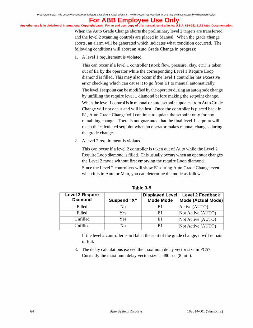
Proprietary Data: This document contains proprietary data of ABB Automation Inc. No disclosure, reproduction, or use may be made except by written permission.
For ABB Employee Use OnlyAny other use is in violatio ion.
64
n of International Copyright Laws. For an end user copy of this manual, send a fax to: U.S.A. 614-261-2172 Attn: Documentat
When the Auto Grade Change aborts the preliminary level 2 targets are transferred and the level 2 scanning controls are placed in Manual. When the grade change aborts, an alarm will be generated which indicates what condition occurred. The following conditions will abort an Auto Grade Change in progress:
1. A level 1 requirement is violated.
This can occur if a level 1 controller (stock flow, pressure, clay, etc.) is taken out of E1 by the operator while the corresponding Level 1 Require Loop diamond is filled. This may also occur if the level 1 controller has excessive error checking which can cause it to go from E1 to manual automatically.
The level 1 setpoint can be modified by the operator during an auto grade change by unfilling the require level 1 diamond before making the setpoint change.
When the level 1 control is in manual or auto, setpoint updates from Auto Grade Change will not occur and will be lost. Once the controller is placed back in E1, Auto Grade Change will continue to update the setpoint only for any remaining change. There is not guarantee that the final level 1 setpoint will reach the calculated setpoint when an operator makes manual changes during the grade change.
2. A level 2 requirement is violated.
This can occur if a level 2 controller is taken out of Auto while the Level 2 Require Loop diamond is filled. This usually occurs when an operator changes the Level 2 mode without first emptying the require Loop diamond.
Since the Level 2 controllers will show E1 during Auto Grade Change even when it is in Auto or Man, you can determine the mode as follows:
If the level 2 controller is in Bal at the start of the grade change, it will remain in Bal.
3. The delay calculations exceed the maximum delay vector size in PC57. Currently the maximum delay vector size is 480 sec (8 min).
Table 3-5
Level 2 RequireDiamond Suspend “X”
Displayed Level Mode Mode
Level 2 Feedback Mode (Actual Mode)
Filled No E1 Active (AUTO)Filled Yes E1 Not Active (AUTO)
Unfilled Yes E1 Not Active (AUTO)
Unfilled No E1 Not Active (AUTO)
Base System Displays 103014-001 (Version E)

Proprietary Data: This document contains proprietary data of ABB Automation Inc. No disclosure, reproduction, or use may be made except by written permission.
For ABB Employee Use OnlyAny other use is in violatio ion.
103014-001 (Vers
n of International Copyright Laws. For an end user copy of this manual, send a fax to: U.S.A. 614-261-2172 Attn: Documentat
Fast Grade Change With Fast Grade Change, the setup and initiating interface is done through the fast grade change display (Figure 3-12). Fast Grade Change adds a special compensation to the stock flow change to help eliminate the moisture upset that occurs during the grade change transition. This stock flow compensation will only be active if the machine speed is ramped during the grade change and the moisture bump reduction feature is enabled. The moisture bump eduction feature is enabled on the Fast Grade Change tuning display. For machine speed increases (sheet weight decreases), the stock flow will temporarily decrease. For machine speed decreases (sheet weight increases), the stock flow will temporarily increase during the fast grade change.
There is also a display link in the upper left hand corner of the Level 1 configuration of the fast grade change summary (Figure 3-12) which displays the Fast Grade Change Grade History display (Figure 3-13). This display shows machine process measurements that were used to achieve the preliminary grade the last three times this grade was produced. This information can be used to apply the correct level 1 control bias based on the past production runs.
Figure 3-13 Fast Grade Change Product Data
65Base System Displaysion E)

Proprietary Data: This document contains proprietary data of ABB Automation Inc. No disclosure, reproduction, or use may be made except by written permission.
For ABB Employee Use OnlyAny other use is in violatio ion.
66
n of International Copyright Laws. For an end user copy of this manual, send a fax to: U.S.A. 614-261-2172 Attn: Documentat
Grade GroupingThe Grade Grouping display lists the data groups required for measurement and control of the designated product code. See Figure 3-14.
To be allowed to make changes to the Grade Grouping or Grade Data displays, you must select the Enable square. Once you have selected and turned on the Enable square, you may make changes to, add, and delete individual data and data groups.
Figure 3-14 Grade Grouping Display
You may select any product code you wish to view. The data for each product code is treated as the preliminary product and will only be used in the event of a grade change or for a sample check.
By selecting the display link to the left of the data group name, you can view the Grade Data display for the chosen group. The grade groups will be numbered from 1 to n. Each grade group contains the data needed for different products.
Base System Displays 103014-001 (Version E)

Proprietary Data: This document contains proprietary data of ABB Automation Inc. No disclosure, reproduction, or use may be made except by written permission.
For ABB Employee Use OnlyAny other use is in violatio ion.
103014-001 (Vers
n of International Copyright Laws. For an end user copy of this manual, send a fax to: U.S.A. 614-261-2172 Attn: Documentat
Grade DataThe Grade Data display allows you to view the individual data involved in the measurement and control of the chosen sensor thoughout the system. Each column of data is a data group. See Figure 3-15.
You may change the group number, get the new group’s data, change the data, and save the changed data. In order to get a new data group, you must go to the Grade Grouping display and select the Enable button. You need the authority key to use the Enable button. Changing the data can be accomplished by simply selecting the item to be modified and entering the new value.
To return to the Grade Grouping display, select the display link labeled “Grade Grouping.”
Figure 3-15 Grade Data Display
67Base System Displaysion E)

Proprietary Data: This document contains proprietary data of ABB Automation Inc. No disclosure, reproduction, or use may be made except by written permission.
For ABB Employee Use OnlyAny other use is in violatio ion.
68
n of International Copyright Laws. For an end user copy of this manual, send a fax to: U.S.A. 614-261-2172 Attn: Documentat
The following is a list of the data pages available for use:
1. Apparent Density 11. Hemi/Reflection Moisture
2. Ash 12. MultiStock
3. Brightness 13. Opacity
4. Basis Weight 14. Smoothness
5. Caliper 15. System
6. Coat Weight 16. Temperature
7. Conditioned Weight 17. Unique
8. Formation 18. X-Ray
9. Gloss 19. Microwave Moisture
10. Air Column
In general, each measurement object (e.g., BW11, MO11, etc.) has preliminary (PPC) and active (APC) grade data structures, where each structure is a 15 element array. For example, APC[1] would be the active target for a given sensor. The generic product code structure is as follows:
pctgt = 1; { target }
pcstd = 2; { standard }
pcpfl = 3; { profile off-spec limit }
pcavl = 4; { average off-spec limit }
pcslp = 5; { calibration slope }
pcoft = 6; { calibration offset }
pcsl1 = 7; { set up parameter 1 }
{ four filter mode - spare }
{ two filter mode - linearization const }
{ sdelta from calibration report }
pcsl2 = 8; { set up parameter 2 }
{ four filter mode - ash compensation }
{ (% of bw units) }
{ two filter mode - weight compensation }
{ (customer units) }
pcsl3 = 13; { set up parameter 3 }
{ refl+, hemi+ 2/4 filter flag }
{ (0=2filter,1=4filter) }
pcsl4 = 14; { set up parameter 4 }
pcsl5 = 15; { set up parameter 5 }
Base System Displays 103014-001 (Version E)

Proprietary Data: This document contains proprietary data of ABB Automation Inc. No disclosure, reproduction, or use may be made except by written permission.
For ABB Employee Use OnlyAny other use is in violatio ion.
103014-001 (Vers
n of International Copyright Laws. For an end user copy of this manual, send a fax to: U.S.A. 614-261-2172 Attn: Documentat
The preliminary and active grade data information for each sensor exists in the AccuRay Processor under:
class MEAS
object id object (e.g. BW11, MO11, etc.)
item id APC(for active product code grade data)
item id PPC(for preliminary product code data)
Grade Data Definitions
Grade Data has four (4) types of components:
• System variables,
• Sensor variables,
• CD variables (refer to the CD Control Tuning Guide 103043-002), and
• Multi-Ply variables (refer to the Multi-Ply Control Tuning Guide 103043-003).
The system variables apply to the Paper Machine in general, and are used mostly in reporting:
TRIM STANDARD - The standard trim size of the sheet being produced. Quality of product is judged by comparing actual to standard. Used in Reel and Grade Reports. Color Control uses trim in the calculation of thruput for dye rate normalization. Ply Loading Control uses trim in stock initialization stock flow calculations and for new grade ply weight if active weight target is zero (not set-up).
REEL SPEED STANDARD - The reel speed standard of the sheet being produced. Quality of product is judged by comparing actual to standard. Used in Reel and Grade Reports.
RUNTIME STANDARD - The standard runtime (non sheetbreak or off-grade) for the sheet being produced. Quality of product is judged by comparing actual to standard, for this item. Used in Reel and Grade Reports.
MACHINE SPEED STANDARD - The standard machine speed of the sheet being produced. Quality of product is judged by comparing actual to standard. Used in Reel and Grade Reports.
REAM SIZE STANDARD - The standard ream size of the sheet being produced. Quality of product is judged by comparing actual to standard, for this item. Used in Reel and Grade Reports. Used by MD Ash Control to calculate process response from clay to ash weight. Also used by Ply Loading Control for stock initialization stock flow calculations and for new grade ply weight if active weight target is zero (not set-up).
RUSH/DRAG SETPOINT - The setpoint for the rush/drag component. Used for Headbox Control setpoint when a grade change is requested.
MACHINE SPEED TARGET - The machine speed target while the sheet is being produced. Coordinated Speed Change uses this target when a grade change is requested.
69Base System Displaysion E)

Proprietary Data: This document contains proprietary data of ABB Automation Inc. No disclosure, reproduction, or use may be made except by written permission.
For ABB Employee Use OnlyAny other use is in violatio ion.
70
n of International Copyright Laws. For an end user copy of this manual, send a fax to: U.S.A. 614-261-2172 Attn: Documentat
SLICE TARGET: The headbox slice target which is used by auto grade change if the slice is configured as the dryline actuator, the slice is in E1 mode at the start of the automatic grade change, and the slice option is enabled on the automatic grade change tuning display.
The sensor variables apply to the particular sensor algorithm. There are different sets based on sensor type (BWxy in the example below). They must always include, (exact set for Basis Weight, Caliper, Formation, Opacity, Brightness, Smoothness, Apparent Density, Gloss, Air Column, Temperature, and X-Ray): TGT, STD, PROF OFF-SPEC LMT, AVG OFF-SPEC LMT, SLOPE CALIB CONST, and OFFSET CALIB CONST. CALIB CONST does not apply for Conditioned Weight.
Ash, Moisture (there are three moisture types: Hemi, Reflection, and Microwave), Coat Weight, and Unique sensor types have additional variables. The “COMP” variables are the values that will be applied in the particular sensor’s algorithm whenever the corresponding coldstart flag requests using grade data information. The “COMP” variables currently applicable on sensors (Ash and Moisture) MUST be initiated via coldstart setup. In the 1190, this is done within PC12, 13, or 32.
BWxy TGT - The target is the amount (desired measured value) of this component in the paper to be produced. If MD Control is configured for this sensor, then this value will be the new target for that sensor when a grade change occurs.
BWxy STD - The standard sensor reading typically required to produce the desired product. Quality of product is judged by comparing actual to standard. Used in Reel and Grade Reports
Note: Typically the TGT should equal STD, the operator can adjust theTGT for the Active Grade to account for extra variables notconsidered, such as environment.
PROF OFF-SPEC LMT - The profile off-specification limit in customer units. The limits are defined as follows:
Scan profile high limit (SHLM) = scan average + APC[3]
Scan profile low limit (SLLM) = scan average - APC[3]
where:APC[n] is the nth element of the Active Product Code
If a profile databox value exceeds either scan high limit or scan low limit, then a dashed horizontal red line will be drawn on the profile display at the high or low profile limit value.
Base System Displays 103014-001 (Version E)

Proprietary Data: This document contains proprietary data of ABB Automation Inc. No disclosure, reproduction, or use may be made except by written permission.
For ABB Employee Use OnlyAny other use is in violatio ion.
103014-001 (Vers
n of International Copyright Laws. For an end user copy of this manual, send a fax to: U.S.A. 614-261-2172 Attn: Documentat
AVG OFF-SPEC LMT - The average off specification limit in customer units. If the profile average value exceeds this limit, an alarm will occur. For a given scan, if
ABS | scan average − target (APC[1]) | > average off-spec limit (APC[4])
where:APC[n] is the nth element of the Active Product Code
then the scan average number will appear in red on the profile display. The Auto Grade Change feature utilizes this value in the off-specification time calculations. Note this off-specification time is the time between grades.
SLOPE CALIB CONST - The slope of the sensor algorithm constant. Used to produce the correct measured value as compared to the known tested samples. Note this value should be from the calibration chart for a value near the standard to be produced.
OFFSET CALIB CNST - The offset of the sensor algorithm constant. Used to produce the measured value as compared to the known tested samples. Note this value should be from the calibration chart for a value near the standard to be produced.
Ash Grade Data has the additional variables:
MOISTURE COMP STD - The value of the moisture to be used as compensation in the Ash algorithm whenever the corresponding coldstart flag requests its use.
WEIGHT COMP STD - The value of basis weight to be used as compensation in the Ash algorithm whenever the corresponding coldstart flag requests its use.
ASH FLAG IN/OUT - The flag for the 3 component Ash sensor is a shielding device which enables the measurement range to be extended. When the flag is out (requested by a 0 value) higher basis weight grades can be measured, conversely when the flag is in (requested by a 1 value) lower basis weight grades can be measured. The 2 component Ash sensor does NOT have a flag, so the measurement range is independent of the value of this variable.
Moisture Grade Data (Hemi, Reflection, and Microwave) has two additional “COMP” variables, which have different meaning depending of type. The IR sensors have an additional filter configuration flag:
2/4 FILTER FLG 0/1 - Flag for IR Moisture sensors which have the capability to alternate between 2 and 4 filter configurations: 0 = 2-filter and 1= 4-filter.
2F-IR LIN, 4F=ASH SCL - When the flag above requests the 2-filter IR configuration, this variable is the grade data value for the linearization constant S-delta (internally known as P-delta). Similarly, when the flag requests 4-filter, this value is the Ash Scaling factor. The value in this variable for a Microwave sensor is the grade data value for Temperature compensation. The actual use of the grade data information is determined by a corresponding coldstart flag.
71Base System Displaysion E)

Proprietary Data: This document contains proprietary data of ABB Automation Inc. No disclosure, reproduction, or use may be made except by written permission.
For ABB Employee Use OnlyAny other use is in violatio ion.
72
n of International Copyright Laws. For an end user copy of this manual, send a fax to: U.S.A. 614-261-2172 Attn: Documentat
IR WEIGHT COMP - When the 2/4 filter flag requests the 2-filter IR configuration, this variable is the grade data value for Basis Weight which can be used as compensation and, for 2-filter Hemi, as part of the moisture calculation. The Microwave sensor also uses this variable for Basis Weight compensation. When the 2/4 filter flag requests 4-filter, this value is the Ash compensation factor. The actual use of the grade data information is determined by a corresponding coldstart flag.
Coat Weight and Unique Grade Data algorithms have many variables and are discussed in the Computed Sensor Variables Manual, 101766-014 Rev. D or later.
Base System Displays 103014-001 (Version E)

Proprietary Data: This document contains proprietary data of ABB Automation Inc. No disclosure, reproduction, or use may be made except by written permission.
For ABB Employee Use OnlyAny other use is in violatio ion.
103014-001 (Vers
n of International Copyright Laws. For an end user copy of this manual, send a fax to: U.S.A. 614-261-2172 Attn: Documentat
Roll Set SummaryThe Roll Set Analysis display allows you to view the current roll information, including trim, average, high and low limit, and 2-Sigma. You can also enter next roll set information and change the profile scale in the profile window. See Figure 3-16.
Figure 3-16 Roll Set Summary Display
• Profile Scale Factors - select to change the scale factor
• Profile High and Low Limits - select to enter a new high or low limit
• Current Roll Statistics - view the current trim, average, high, low, and 2-Sigma for each roll; the high/low will turn red if they are above/below the limit
• Current Set - view the length, footage, reel, set, # rolls, and trim for the current roll set
• Next Set - select and enter the length, footage, reel, set, # rolls, and trim for the next roll set
• Next Set Trim - select and enter the trim for the next roll set
• Trim - if the trim value is above the limit, the next set trim value will be red
73Base System Displaysion E)

Proprietary Data: This document contains proprietary data of ABB Automation Inc. No disclosure, reproduction, or use may be made except by written permission.
For ABB Employee Use OnlyAny other use is in violatio ion.
74
n of International Copyright Laws. For an end user copy of this manual, send a fax to: U.S.A. 614-261-2172 Attn: Documentat
Composite Profile DisplaysGeneral Information
Each plot is a filtered composite profile of the selected measurement. See Figure 3-17, Figure 3-18, and Figure 3-19. Single scan profiles can be selected for individual measurements by disabling compositing on the Measurement Overview display.
Figure 3-17 Composite Profile (1 Window) Display
Base System Displays 103014-001 (Version E)

Proprietary Data: This document contains proprietary data of ABB Automation Inc. No disclosure, reproduction, or use may be made except by written permission.
For ABB Employee Use OnlyAny other use is in violatio ion.
103014-001 (Vers
n of International Copyright Laws. For an end user copy of this manual, send a fax to: U.S.A. 614-261-2172 Attn: Documentat
Figure 3-18 Composite Profile (2 Windows) Display
75Base System Displaysion E)

Proprietary Data: This document contains proprietary data of ABB Automation Inc. No disclosure, reproduction, or use may be made except by written permission.
For ABB Employee Use OnlyAny other use is in violatio ion.
76
n of International Copyright Laws. For an end user copy of this manual, send a fax to: U.S.A. 614-261-2172 Attn: Documentat
Figure 3-19 Composite Profile (3 Windows) Display
Measurement Selection
You may select the measurement whose statistics you wish to view by using the following procedure:
1. Select the “M” button to open the measurement selection menu window.
2. Place the cursor over the desired measurement.
3. Press Select.
4. Press OK.
Active Grade Data Target
This value is the active grade data target of the selected measurement.
Numeric Print
Selecting the “P” button will enter a request to print the composite profile numeric data.
Base System Displays 103014-001 (Version E)

Proprietary Data: This document contains proprietary data of ABB Automation Inc. No disclosure, reproduction, or use may be made except by written permission.
For ABB Employee Use OnlyAny other use is in violatio ion.
103014-001 (Vers
n of International Copyright Laws. For an end user copy of this manual, send a fax to: U.S.A. 614-261-2172 Attn: Documentat
Profile Windows
You may select different areas of the profile window. If you select a point in the profile area, you can zoom in on a portion of the profile. If you choose one of the values on the Y-axis, you can change the range of the plot or hide the plot.
Note: A red dashed line appears to indicate that a plot is out ofspecification. The end of the dashed line will extend into the Y-axiswindow for the plot which is out of specification.
Zooming the Profile
To select and view the zoom area, complete the following steps:
1. With the cursor in the plot window, press select to set the ruler position. This action will activate the ruler dialog.
2. Hold down the select button and move the cursor.
3. Release the select button to set the zoom boundary.
4. The ruler may be moved using the dialog keys:
<<: Moves ruler 10 data points to the left
<: Moves ruler 1 data points to the left
>: Moves ruler 1 data points to the right
>>: Moves ruler 10 data points to the right
5. Select the zoom button to view the area between the ruler and the zoom boundary expanded horizontally to fill the plot window.
6. Select the zoom button again to return to the original profile
While the ruler dialog is active, the Y value at the ruler position for each plot is displayed below the plot window. While zoom is active, a bar will appear at the bottom edge of the plot window. This zoom bar indicates the portion of the plot being viewed in relation to the full plot.
Vertical Plot Characteristics
Note: Selecting anywhere within the the Y-axis window will open the Y-axis dialog for the plot of the same color. The Y-axis display valueswill turn red if they are out of specifications.
Once you have selected the Y-axis you may select the range, the offset, an auto range, or to hide the profile. The range of the display is the amount between the display maximum and the display minimum. The offset shifts the plot up or down along the Y-axis; this movement may improve visibility when more than one plot is present. The hide function will make the plot invisible; pressing hide again will make it reappear. Auto range is a display mode which automatically calculates a new value for range each time the plot is updated by the platform. The value of the range is a percentage of the vertical space in the plot display window. Once activated, auto range remains active until the auto range button is selected again or the range button is selected.
77Base System Displaysion E)

Blank Page

Proprietary Data: This document contains proprietary data of ABB Automation Inc. No disclosure, reproduction, or use may be made except by written permission.
For ABB Employee Use OnlyAny other use is in violatio ion.
103014-001 (Vers
n of International Copyright Laws. For an end user copy of this manual, send a fax to: U.S.A. 614-261-2172 Attn: Documentat
4Hardcopy Reports
Chapter Four provides examples of the hardcopy reports and describes the information provided in them.
This chapter contains the following major sections:
Section ...............................................................................................Page
Reel and Grade Reports ................................................................................. 80Shift/Day Report ............................................................................................ 84
79Hardcopy Reportsion E)

Proprietary Data: This document contains proprietary data of ABB Automation Inc. No disclosure, reproduction, or use may be made except by written permission.
For ABB Employee Use OnlyAny other use is in violatio ion.
80
n of International Copyright Laws. For an end user copy of this manual, send a fax to: U.S.A. 614-261-2172 Attn: Documentat
Reel and Grade ReportsThe Reel Report provides summarized reel data. Figure 4-1 on page 82 shows an example of a Reel Report. The Grade Report provides summarized grade data. Figure 4-2 on page 83 shows an example of a Grade Report. The Grade Report provides data across a larger time span than the Reel Report does. The Grade Report also notes the time used to bring the product on grade. If the system has been restarted during the production of a grade, the Grade Report prints a warning concerning the validity of the data.
The Reel and Grade Reports are divided into the following sections:
• Heading
• Production Summary
• Quality Analysis
Heading
The heading of the Shift/Day Report consists of the paper machine number and the date of the report.
Production Summary
The Production Summary section of the Reel and Grade Reports contains the following information:
• Production
• Thruput
• Reel Speed
• Actual Paper Machine Run Time and Lost Time
• Grade Change (Grade Report only)
Figure 4-1 on page 82 shows how the system calculates these values.
Note: EFFICIENCIES = 100 x ACTUAL/STANDARD (not calculated forrun and lost time).
Table 4-1 uses the variable UFCTR. UFCTR is the units factor that resolves units in some calculations:
English Units
International Units
UFCTR 1.44 106×=
UFCTR 6.0 109×=
Hardcopy Reports 103014-001 (Version E)

Proprietary Data: This document contains proprietary data of ABB Automation Inc. No disclosure, reproduction, or use may be made except by written permission.
For ABB Employee Use OnlyAny other use is in violatio ion.
103014-001 (Vers
n of International Copyright Laws. For an end user copy of this manual, send a fax to: U.S.A. 614-261-2172 Attn: Documentat
Table 4-1 Production Summary Variables
Note: Standards are from the product code file.
Quality Analysis
The Reel and Grade Reports provide a summary of the average values of process variables. The Quality Analysis section consists of the information in Table 4-2.
Table 4-2 Quality Analysis Information
Variable Standard Actual
Production Throughput Std x Run Time Std3600
Footage x Trim x BWReam Size x UFCTR
Thruput Speed Std x BW Std x Trim StdUFCTR x Ream Size x 3600
Production x 3600Run Time
Reel Speed Speed Std Accumulated Ft.Run Time
Run Time (Run + Lost Time) x Run Time Factor
Time other than lost or grade change time
Lost Time (Run + Lost Time) x [1 - (Run Time Factor)]
Measured Sheet Break
Grade Change (Grade
Report only)
Time required to make grade change not
included in other times
Item Description
Target The last target entered by the operator
Actual The average value for the grade
Efficiency A measure of the actual value to the target either to minimize or maximize the variable
RES Residual Deviation is the variability in the number of standard deviations (in process units) that is not long-term machine direction variability (MDL) or CD variability (CD). It may also be referred to as short-term machine direction variability (MDS).
MDL The number of standard deviations (in process units) that is Machine Direction Long-Term variability.
CD Cross Direction variability is the number of standard deviations (in process units) for the average profile variation.
TOT Total Variability is the number of standard deviations (in process units) for all data points for all scans.
81Hardcopy Reportsion E)

Proprietary Data: This document contains proprietary data of ABB Automation Inc. No disclosure, reproduction, or use may be made except by written permission.
For ABB Employee Use OnlyAny other use is in violatio ion.
82
n of International Copyright Laws. For an end user copy of this manual, send a fax to: U.S.A. 614-261-2172 Attn: Documentat
Variance Partition Analysis (VPA) exists for each measured process variable. VPA calculates short-term and long-term machine direction, cross direction, and total variabilities. VPA displays values in the units of the associated process variable. You can configure VPA to show variabilities in terms of variance, standard deviation, or coefficient.
Printing the Report
The Reel Report (Figure 4-1) prints out when you select a reel turn-up or request a grade change. The Grade Report (Figure 4-2) prints out when you request a grade change.
Figure 4-1 Reel Report Example
REEL REPORT
MACHINE 8 START:1990-12-1015:40PRODUCT 1190 PRODUCT NAME 12#_ALPENO_CANEND: 1990-12-1015:47
PRODUCTION SUMMARYSTANDARD ACTUAL EFFICIENCY
PRODUCTION TONS 0.99 1.14 115:27THRUPUT T/HR 10.28 10.67 103.74
REEL SPEED FT/MIN 1990.00 2000.00 100.50RUN TIME HR:MIN 0: 6 0: 6
QUALITY ANALYSIS
BASIS WT 1LBSTarget Actual Efficiency RES MDL CD TOT
100.00 100.00 100.00 1.00 2.00 3.00 4.00MOISTURE 1PCT
Target Actual Efficiency RES MDL CD TOT6.0 6.0 100.00 1.00 2.00 3.00 4.00
COND WT 1LBSTarget Actual Efficiency RES MDL CD TOT
100.00 100.00 100.00 1.00 2.00 3.00 4.00CALIPERMILS
Target Actual Efficiency RES MDL CD TOT2.6 2.6 100.00 1.00 2.00 3.00 4.00
OPACITYPTSTarget Actual Efficiency RES MDL CD TOT
86 86 100.00 1.00 2.00 3.00 4.00BASIS WT 2LBS
Target Actual Efficiency RES MDL CD TOT90 90 100.00 1.00 2.00 3.00 4.00
MOISTURE 2PCTTarget Actual Efficiency RES MDL CD TOT
6.0 6.0 100.00 1.00 2.00 3.00 4.00COND WT 2LBS
Target Actual Efficiency RES MDL CD TOT90 90 100.00 1.00 2.00 3.00 4.00
Hardcopy Reports 103014-001 (Version E)

Proprietary Data: This document contains proprietary data of ABB Automation Inc. No disclosure, reproduction, or use may be made except by written permission.
For ABB Employee Use OnlyAny other use is in violatio ion.
103014-001 (Vers
n of International Copyright Laws. For an end user copy of this manual, send a fax to: U.S.A. 614-261-2172 Attn: Documentat
Figure 4-2 Grade Report Example
GRADE REPORT
MACHINE 8 START:1990-12-1015:40
PRODUCT 1190 PRODUCT NAME 12#_ALPENO_CANEND: 1990-12-1015:47
PRODUCTION SUMMARYSTANDARD ACTUAL EFFICIENCY
PRODUCTION TONS 0.99 1.14 115:27
THRUPUT T/HR 10.28 10.67 103.74REEL SPEED FT/MIN 1990.00 2000.00 100.50
RUN TIME HR:MIN 0: 6 0: 6LOST TIME HR:MIN 0: 1 0: 0
GRADE CHANGE HR:MIN 0: 1 0: 0
QUALITY ANALYSISBASIS WT 1LBS
Target Actual Efficiency RES MDL CD TOT1000.00 1000.00 100.00 1.00 2.00 3.00 4.00
MOISTURE 1PCTTarget Actual Efficiency RES MDL CD TOT
1000.00 1000.00 100.00 1.00 2.00 3.00 4.00COND WT 1LBS
Target Actual Efficiency RES MDL CD TOT1000.00 1000.00 100.00 1.00 2.00 3.00 4.00
CALIPERMILSTarget Actual Efficiency RES MDL CD TOT
1000.00 1000.00 100.00 1.00 2.00 3.00 4.00OPACITYPTS
Target Actual Efficiency RES MDL CD TOT1000.00 1000.00 100.00 1.00 2.00 3.00 4.00
BASIS WT 2LBSTarget Actual Efficiency RES MDL CD TOT
1000.00 1000.00 100.00 1.00 2.00 3.00 4.00MOISTURE 2PCT
Target Actual Efficiency RES MDL CD TOT1000.00 1000.00 100.00 1.00 2.00 3.00 4.00
COND WT 2LBSTarget Actual Efficiency RES MDL CD TOT
1000.00 1000.00 100.00 1.00 2.00 3.00 4.00FORMATIONROD
Target Actual Efficiency RES MDL CD TOT1000.00 1000.00 100.00 1.00 2.00 3.00 4.00
BRIGHTNESSPTSTarget Actual Efficiency RES MDL CD TOT
1000.00 1000.00 100.00 1.00 2.00 3.00 4.00
83Hardcopy Reportsion E)

Proprietary Data: This document contains proprietary data of ABB Automation Inc. No disclosure, reproduction, or use may be made except by written permission.
For ABB Employee Use OnlyAny other use is in violatio ion.
84
n of International Copyright Laws. For an end user copy of this manual, send a fax to: U.S.A. 614-261-2172 Attn: Documentat
Shift/Day ReportThe Shift/Day Report shows the mill variables and automatic control usage for each shift and the entire day. Figure 4-3 below shows an example of a Shift/Day Report. The report consists of the three sections listed below.
• Heading
• Production Summary
• % Control Time
Figure 4-3 Shift/Day Report Example
Heading
The heading of the Shift/Day Report consists of the paper machine number and the date of the report.
Production Summary
The Production Summary section provides information on each shift and the entire day. The information in this section includes the following:
• Production
• Thruput
• Reel Speed
• Run Time
• Lost Time
• Grade Change
SHIFT/DAY REPORT
MACHINE 8 DATE:1990-12-10
PRODUCTION SUMMARY
SHIFT 1 SHIFT 2 SHIFT 3 DAY
PRODUCTION TONS 3.59 85.32 85.32 174.16
THRUPUT T/HR 10.67 10.67 10.67 10.66REEL SPEED FT/MIN 1999.99 1999.57 1999.57 2000.89
RUN TIME HR:MIN 0:20 8:0 8:0 16:20LOST TIME HR:MIN 0:0 0:0 0:0 0:0
GRADE CHANGE HR:MIN 0:0 0:0 0:0 0:0
BASIS WT 1 PCT 100.0 100.0 0.0 100.0
MOISTURE 1 PCT 0.0 0.0 0.0 0.0MOISTURE 2 PCT 100.0 100.0 0.0 100.0
DRYSTOCK PCT 0.0 0.0 0.0 0.0
OPACITY PCT 0.0 0.0 0.0 0.0HEADBOX PCT 100.0 100.0 0.0 100.0
SPEED CHANGE PCT 0.0 0.0 0.0 0.0CROSS MACHINE PCT 0.0 0.0 0.0 0.0
% CONTROL TIME
Hardcopy Reports 103014-001 (Version E)

Proprietary Data: This document contains proprietary data of ABB Automation Inc. No disclosure, reproduction, or use may be made except by written permission.
For ABB Employee Use OnlyAny other use is in violatio ion.
103014-001 (Vers
n of International Copyright Laws. For an end user copy of this manual, send a fax to: U.S.A. 614-261-2172 Attn: Documentat
The system calculates each variable on a per shift basis. Shift values for the throughput and speed are averaged for the day, while production, run times, and lost time shift values are added together to get a day total. Information in this section is reset at the end of the mill “day.”
% Control Time
The % Control Time section lists each auto control option which is present in the system and gives the percentage of each shift the auto control loop was active. The system averages the shift values into daily values.
Printing the Report
The Shift/Day Report prints out between shifts 3 and 1.
85Hardcopy Reportsion E)

Blank Page

Proprietary Data: This document contains proprietary data of ABB Automation Inc. No disclosure, reproduction, or use may be made except by written permission.
For ABB Employee Use OnlyAny other use is in violation of International Copyright Laws. For an end user copy of this manual, send a fax to: U.S.A. 614-261-2172 Attn: Documentation.
103014
Index
AAccuRay 1190 Overview, 1
control overview, 7auto grade change, 8coordinated dryer, 8cross direction, 9drystock flow, 8headbox, 7multiply, 9scanning process, 7speed, 7
hardware overview, 3actuators, 5Advant operator station, 3Advant operator station keyboard, 4electronics cabinet, 3platform, 3printers, 5
measurement overview, 6system overview, 2
Acknowledging alarms, 32extended information, 33from object displays, 32from process alarm list, 32from process displays, 32
Auto grade change summary display, 60ramping auto grade change, 62setting up auto grade change, 60
BBase System Displays
fast grade change, 65
CComposite profile displays, 74
active grade data target, 76measurement selection, 76numeric print, 76profile windows, 77
vertical plot characteristics, 77zooming the profile, 77
Control overview, 7auto grade change, 8coordinated dryer, 8
dryer loading, 8dryer ramping, 8
cross direction, 9caliper, 9moisture, 9weight, 9
drystock flow, 8headbox, 7multiply, 9, 10scan-based MD, 7speed, 7
expert speed, 7speed optimization, 8
Cursor control, 19mouse, 19trackball, 19
DDisplay layout, 14Display links, 18
assignable keys, 18Dkeys, 18icons, 18
Display types, 12help, 13overlap, 13process, 12system, 12trend, 12
FFast Grade Change, 65Frame overview display, 39
changing measurement modes, 40sample check overlap display, 40
ash flag, 41compensation values, 41sample check modes, 41
GGrade data display, 67Grade grouping display, 66Grade reports, 80
87Index-001 (Version E)

Proprietary Data: This document contains proprietary data of ABB Automation Inc. No disclosure, reproduction, or use may be made except by written permission.
For ABB Employee Use OnlyAny other use is ion.
88
in violation of International Copyright Laws. For an end user copy of this manual, send a fax to: U.S.A. 614-261-2172 Attn: Documentat
HHardcopy reports, 79
reel and grade, 80shift/day, 84
Hardware overview, 3actuators, 5Advant operator station, 3Advant operator station keyboard, 4electronics cabinet, 3platform, 3printers, 5
Headbox control summary display, 45
MMachine direction control display, 50
level 1 controls, 51changing manual output, 52
level 2 controls, 52changing drystock, 52
process overview, 52Measurement overview, 6Measurement overview display, 46
disable profile compositing, 47print history, 47report print on/off, 46
Measurement status display, 48calibrate sample, 49grade data, 49measurement selection, 48sample check, 49sensor calibration data, 49sensor local modes, 49sensor status, 49standardize, 49
OOperating procedures, 11
acknowledging alarms, 32extended information, 33from object displays, 32from process alarm list, 32from process displays, 32
changing the mode, 30changing the setpoint, 30controlling the cursor, 19
mouse, 19trackball, 19
printing video displays, 34restarting the system, 35selecting items, 23
objects, 29
video displays, 23understanding the video displays, 12
1190 specific symbols, 17display layout, 14display links, 18display types, 12screen colors, 15symbol codes, 16
using the keys, 20operator station keys, 20
PPaper machine overview display, 42
determining frame status, 44dryer ramping/loading, 44interpreting control loops, 43
Printing video displays, 34Production summary display, 53Profile displays, 74
active grade data target, 76measurement selection, 76numeric print, 76profile windows, 77
vertical plot characteristics, 77zooming the profile, 77
RReel Reports, 80Restarting the system, 35Roll set summary display, 73
SScreen colors, 15Selection, 23
objects, 29video display, 23
direct selection keys, 24display links, 23when you do not know the identifier, 24
Shift/Day report, 84Speed control summary display, 54
aborting a speed change, 56changing controller to Auto, 55expert speed setpoint handler, 57initiating a speed change, 55interpreting alarms, 59speed optimization, 58
Symbol codes, 16Symbols
1190 specific, 17frame status, 17
103014-001 (Version E)Index

Proprietary Data: This document contains proprietary data of ABB Automation Inc. No disclosure, reproduction, or use may be made except by written permission.
For ABB Employee Use OnlyAny other use is ion.
103014
in violation of International Copyright Laws. For an end user copy of this manual, send a fax to: U.S.A. 614-261-2172 Attn: Documentat
operator action, 17System overview, 2System overview display, 38
UUsing the keys, 20
operator station keys, 20
VVideo displays, 37
auto grade change summary, 60
composite profiles, 74frame overview, 39grade data, 67grade grouping, 66headbox control summary, 45machine direction control, 50measurement overview, 46measurement status, 48paper machine overview, 42production summary, 53roll set summary, 73speed control summary, 54system overview, 38
-001 (Version E) 89Index

Blank Page