
Antisurge Control
44
1 /44 /44 ANTI-SUGRE CONTROL ( COKER GAS COMPRESSOR)
description
Antisurge Control
Transcript of Antisurge Control

11/44/44
ANTI-SUGRE CONTROL ( COKER GAS COMPRESSOR)

22
Surge definitionSurge definition
Self oscillations of pressure and flow, often Self oscillations of pressure and flow, often including a flow reversal in the centrifugal including a flow reversal in the centrifugal and axial compressors is known as surgingand axial compressors is known as surging

33
Surge descriptionSurge description
Flow reversal in 20 to 50 milli secondsFlow reversal in 20 to 50 milli secondsSurge cycles at a rate of 0.3s to 3 s per cycleSurge cycles at a rate of 0.3s to 3 s per cycleCompressor vibratesCompressor vibratesTemperature risesTemperature rises““whooshing” noise or “Clanking” noisewhooshing” noise or “Clanking” noiseTrip may occurTrip may occurConventional instruments /human operators Conventional instruments /human operators may fail to recognise surgemay fail to recognise surge

44/44/44
CONDITIONS THAT CAN LEAD TO CONDITIONS THAT CAN LEAD TO SURGESURGE
Rise in discharge pressure when suction pressure Rise in discharge pressure when suction pressure and RPM held constantand RPM held constant
Fall in suction pressure when discharge pressure Fall in suction pressure when discharge pressure and RPM held constantand RPM held constant
Fall in RPM, when suction and discharge pressure Fall in RPM, when suction and discharge pressure held constant can quickly drop flow to surge limitheld constant can quickly drop flow to surge limit
Other process changes like drop in molecular Other process changes like drop in molecular weight or specific gravity of the gas weight or specific gravity of the gas
Start up, shutdown, reduced through putStart up, shutdown, reduced through put Heavy throughput with trips, operator error,Heavy throughput with trips, operator error, load change, cooler problem, driver problemload change, cooler problem, driver problem

55/44/44
SurgeSurge leads toleads to ……
Once surge is induced, the flow rate & pressure Once surge is induced, the flow rate & pressure will oscillate drastically until the cause is will oscillate drastically until the cause is removed or protective devices shut down the removed or protective devices shut down the machine or a failure occurs.machine or a failure occurs.
The excessive thrust bearing & impeller loads, The excessive thrust bearing & impeller loads, vibration & rising gas temperatures associated vibration & rising gas temperatures associated with surge can produce process upsets & with surge can produce process upsets & severe compressor damage if more than a very severe compressor damage if more than a very few surge cycles are experienced.few surge cycles are experienced.

66/44/44
To prevent Compressor Damage due to surge To prevent Compressor Damage due to surge or Process Upset without sacrificing energy or Process Upset without sacrificing energy efficiency or system capacityefficiency or system capacity To maintain selected process variables within To maintain selected process variables within Safe or acceptable rangesSafe or acceptable ranges
ObjectiveObjective of Surge Protection Systemsof Surge Protection Systems

77/44/44
Basic antisurge control system
Compressor
FT PT PT
UIC
Suction Discharge
VSDS
TT
TT

88/44/44
How to preventHow to prevent
A Anti surge system achieve this A Anti surge system achieve this By manipulating the positions of Recycle By manipulating the positions of Recycle
valve (Normally for Hazardous Gas)valve (Normally for Hazardous Gas) By using a Blow off valve (Normally for Air By using a Blow off valve (Normally for Air
or Non hazardous applications)or Non hazardous applications)
Opening of recycle valve lowers the resistance Opening of recycle valve lowers the resistance felt by the compressorfelt by the compressor
This takes the compressor away from surge This takes the compressor away from surge
99/44/44
The challengesThe challenges
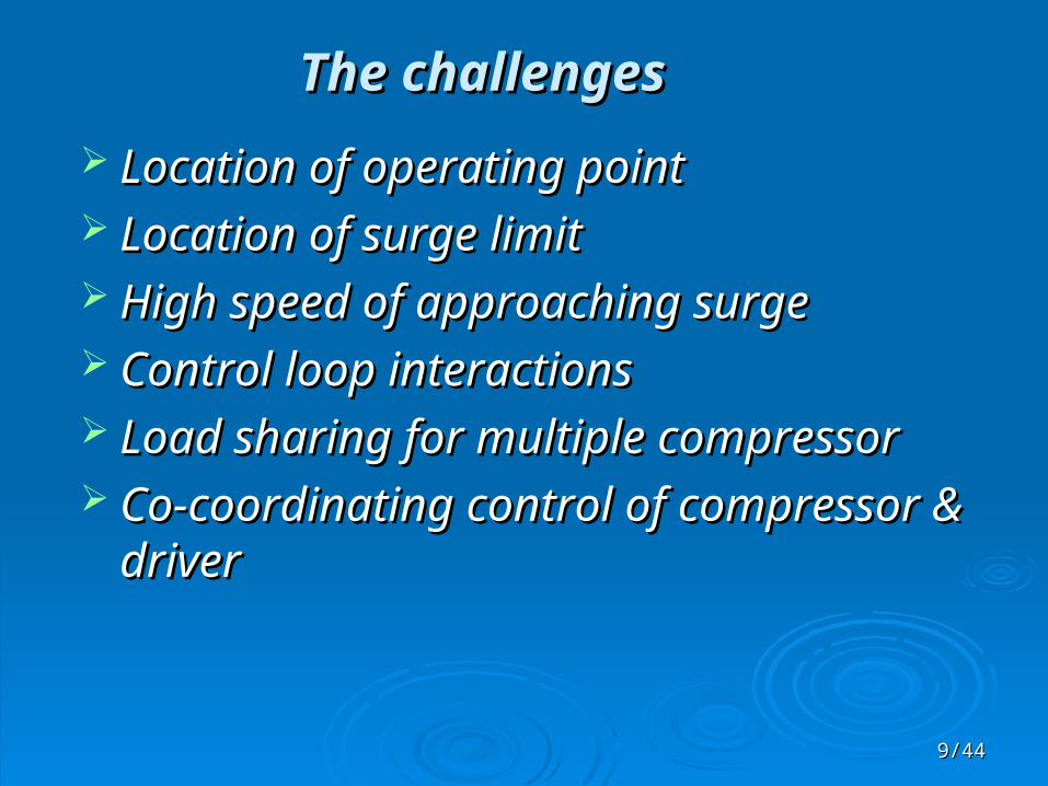
Location of operating pointLocation of operating point Location of surge limitLocation of surge limit High speed of approaching surgeHigh speed of approaching surge Control loop interactionsControl loop interactions Load sharing for multiple compressorLoad sharing for multiple compressor Co-coordinating control of compressor & Co-coordinating control of compressor &
driverdriver

1010/44/44
Surge Limit LineSurge Control Line
Maximum Pressure
Surge Control Zone
1’1”
1’”1
2’2”
2
Hp
Q s
2
Antisurge Controller Actions
1111/44/44
Control Actions …Control Actions …
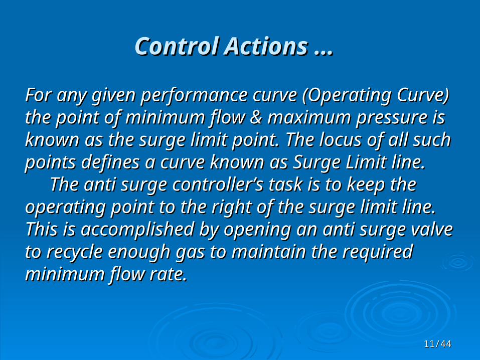
For any given performance curve (Operating Curve) For any given performance curve (Operating Curve) the point of minimum flow & maximum pressure is the point of minimum flow & maximum pressure is known as the surge limit point. The locus of all such known as the surge limit point. The locus of all such points defines a curve known as Surge Limit line. points defines a curve known as Surge Limit line. The anti surge controller’s task is to keep the The anti surge controller’s task is to keep the operating point to the right of the surge limit line. operating point to the right of the surge limit line. This is accomplished by opening an anti surge This is accomplished by opening an anti surge valve to recycle enough gas to maintain the valve to recycle enough gas to maintain the required minimum flow rate.required minimum flow rate.

1212/44/44
Control Actions …Control Actions …
However, because the dynamics of the system are However, because the dynamics of the system are inherently slow, this control action must be started inherently slow, this control action must be started before the operating point reaches the surge limit. before the operating point reaches the surge limit. The point at which the controller starts to open the The point at which the controller starts to open the valve is known as Surge Control Point. The locus of valve is known as Surge Control Point. The locus of all such points defines a surge control line. The all such points defines a surge control line. The Distance between SCL& SLL is refereed as the Distance between SCL& SLL is refereed as the margin of safety. Region left to the SCL is known as margin of safety. Region left to the SCL is known as Surge Control Zone.Surge Control Zone. Anti surge Controller starts opening the recycle Anti surge Controller starts opening the recycle valve, When ever the operating point is in the Surge valve, When ever the operating point is in the Surge Control ZoneControl Zone
1313/44/44
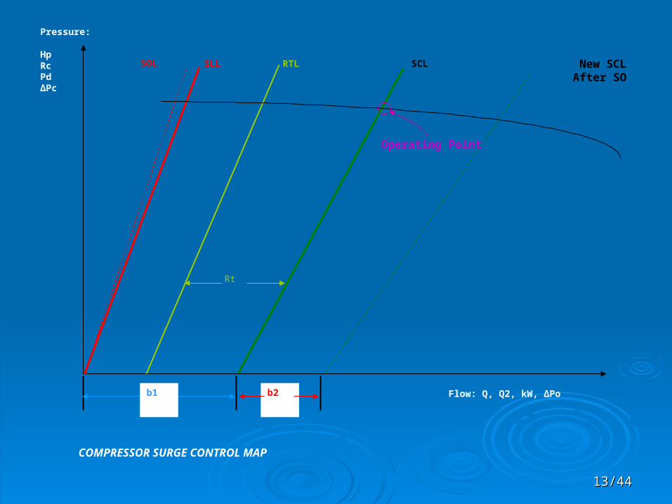
b1 b2
SOL SLL RTL SCL New SCLAfter SO
Operating Point
Pressure:
HpRc Pd ∆Pc
Flow: Q, Q2, kW, ∆Po
Rt
COMPRESSOR SURGE CONTROL MAP

1414/44/44
Control LinesControl Lines SCL: Surge Control Line.. The line on the compressor map SCL: Surge Control Line.. The line on the compressor map
where the open loop RT response is triggered.where the open loop RT response is triggered. RTL: Recycle Trip Line.. The line on the compressor map where RTL: Recycle Trip Line.. The line on the compressor map where
the open loop RT response is triggered.the open loop RT response is triggered. SLL: Surge Limit Line.. The line on the compressor map which SLL: Surge Limit Line.. The line on the compressor map which
represents where the surge happens. If the OP is left of the SLL, represents where the surge happens. If the OP is left of the SLL, surge occurs.surge occurs.
SOL: Safety On Line.. The line on the compressor map where the SOL: Safety On Line.. The line on the compressor map where the controller recognises surge and the Safety On response is controller recognises surge and the Safety On response is triggeredtriggered
Anti surge Controller calculates proximity to surge on the Anti surge Controller calculates proximity to surge on the distance between the operating point of the compressor & the distance between the operating point of the compressor & the Surge Limit line (SLL). The Controller also calculates other Surge Limit line (SLL). The Controller also calculates other control lines on the compressor map which are used to control lines on the compressor map which are used to determine its control responses & actions. These lines are determine its control responses & actions. These lines are determined relative to either the SLL or the Surge Control Line.determined relative to either the SLL or the Surge Control Line.

1515/44/44
Control Actions …Control Actions …
Various Control actions are triggered when the operating Various Control actions are triggered when the operating point of the compressor crosses the control lines :point of the compressor crosses the control lines :
The anti surge PI response increases the recycle rate when The anti surge PI response increases the recycle rate when the operating point is to the left of the SCL & reduces it the operating point is to the left of the SCL & reduces it when the point is to the right of the SCL.when the point is to the right of the SCL.
The recycle trip response steps the anti surge valve open The recycle trip response steps the anti surge valve open when the operating point is to the left of the Recycle Trip when the operating point is to the left of the Recycle Trip Line (RTL).Line (RTL).
The Safety on response moves SCL & RTL control lines to The Safety on response moves SCL & RTL control lines to the right if the operating point moves to the left of the safety the right if the operating point moves to the left of the safety on line(SOL).on line(SOL).
The tight shutoff response fully closes the anti surge valve The tight shutoff response fully closes the anti surge valve when the operating point is to the right of the Tight Shutoff when the operating point is to the right of the Tight Shutoff Line(TSL) & the control signal is at its minimum clamp.Line(TSL) & the control signal is at its minimum clamp.
1616/44/44
Why not on DCS Why not on DCS
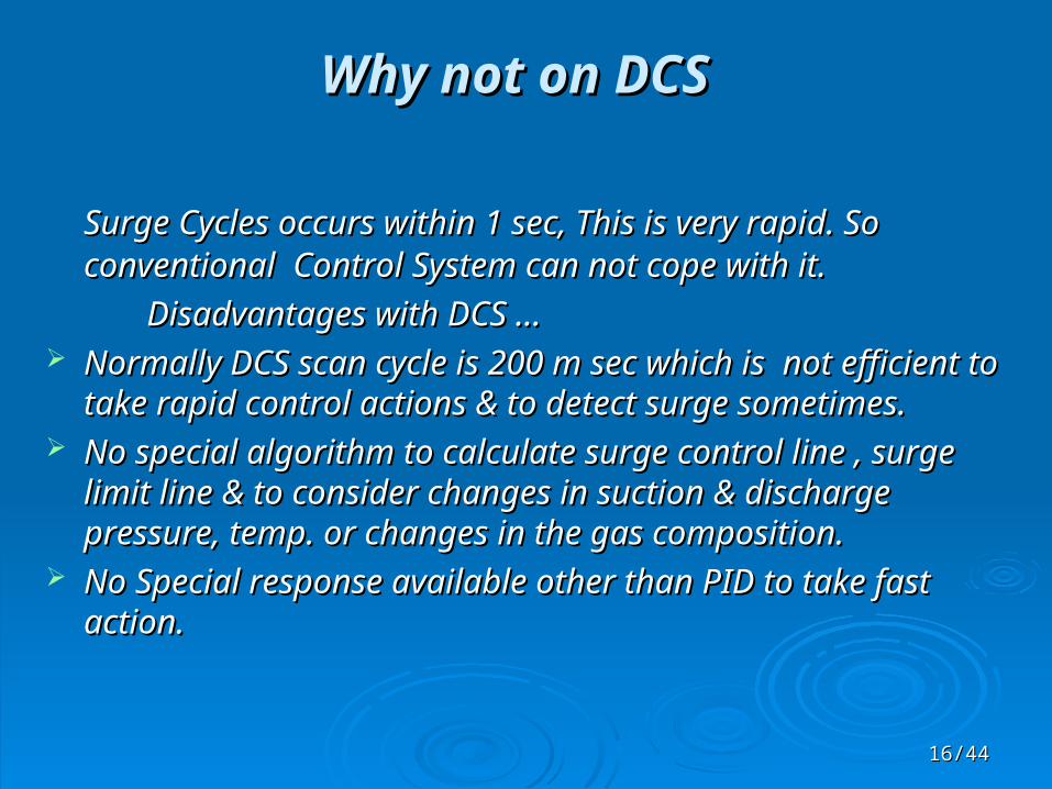
Surge Cycles occurs within 1 sec, This is very rapid. So Surge Cycles occurs within 1 sec, This is very rapid. So conventional Control System can not cope with it.conventional Control System can not cope with it.
Disadvantages with DCS …Disadvantages with DCS … Normally DCS scan cycle is 200 m sec which is not efficient Normally DCS scan cycle is 200 m sec which is not efficient
to take rapid control actions & to detect surge sometimes.to take rapid control actions & to detect surge sometimes. No special algorithm to calculate surge control line , surge No special algorithm to calculate surge control line , surge
limit line & to consider changes in suction & discharge limit line & to consider changes in suction & discharge pressure, temp. or changes in the gas composition.pressure, temp. or changes in the gas composition.
No Special response available other than PID to take fast No Special response available other than PID to take fast action.action.

1717/44/44
CCC Anti Surge ControllersCCC Anti Surge Controllers CCC is a high speed control system with precise control CCC is a high speed control system with precise control algorithms provides safe & efficient surge protection with algorithms provides safe & efficient surge protection with stable & precise process control which has following stable & precise process control which has following advantages over DCS system.advantages over DCS system.
CCC scan cycle is 40 m sec which is fast enough to take CCC scan cycle is 40 m sec which is fast enough to take control action & surge detection.control action & surge detection.
Precise algorithms to locate the surge limit regardless of Precise algorithms to locate the surge limit regardless of compressor operating condition.compressor operating condition.
Special responses like Recycle trip, Safety on, Derivative Special responses like Recycle trip, Safety on, Derivative other than conventional PID.other than conventional PID.
Loop De coupling between anti-surge & process control Loop De coupling between anti-surge & process control system to avoid control loop interactions.system to avoid control loop interactions.
Fall back strategies.Fall back strategies.
1818/44/44
CCC Anti Surge ControllersCCC Anti Surge Controllers
CCC gives Anti Surge Controllers in Two Basic ModelsCCC gives Anti Surge Controllers in Two Basic Models Series 3 (Single loop Applications)Series 3 (Single loop Applications) Series 4 (Advance Application Module, Several primary Series 4 (Advance Application Module, Several primary
loops)loops) Series 3 Anti surge Controller can be used to protect a Series 3 Anti surge Controller can be used to protect a
single-section centrifugal or Axial Compressor from Surge single-section centrifugal or Axial Compressor from Surge or it can be combined with other Series 3 Controller to or it can be combined with other Series 3 Controller to protect multi section compressors or compressor protect multi section compressors or compressor network.Series 3 is like a Single loop controller.network.Series 3 is like a Single loop controller.
Series 4 Controllers are for more Complex Controls & Series 4 Controllers are for more Complex Controls & protection of machines (Like Reactor /Regenerator of a protection of machines (Like Reactor /Regenerator of a FCC Unit) .Series 4 is more like a PLC with Main FCC Unit) .Series 4 is more like a PLC with Main Processor modules, Input /Output Modules with Simplex, Processor modules, Input /Output Modules with Simplex, Duplex or triplex redundancy level.Duplex or triplex redundancy level.
1919/44/44
Series 3 ControllersSeries 3 Controllers Redundant Control Redundant Control : Main Controller & its backup : Main Controller & its backup
should be installed & configured exactly alike & must be should be installed & configured exactly alike & must be connected via their serial port no.1connected via their serial port no.1
Redundant controller track the status of the Active controller Redundant controller track the status of the Active controller & automatically transfer control to the backup by the fault relay & automatically transfer control to the backup by the fault relay of the main controller.of the main controller.
Manual OperationManual Operation : The operator can directly control the : The operator can directly control the position of the anti surge valve by using front panel Auto/Man position of the anti surge valve by using front panel Auto/Man key to control the position of anti surge valve. When controller is key to control the position of anti surge valve. When controller is in this mode, New Output value is calculated by incrementing or in this mode, New Output value is calculated by incrementing or decrementing its previous value whenever front panel up or decrementing its previous value whenever front panel up or down key is pressed.down key is pressed.
Automatic mode can be restores by pressing the Auto/Man key Automatic mode can be restores by pressing the Auto/Man key second time. A Bump less transfer algorithm is used to prevent second time. A Bump less transfer algorithm is used to prevent sudden changes to the output which might upset the sudden changes to the output which might upset the compression system.compression system.

2020/44/44
Series 3 ControllersSeries 3 Controllers
Manual Override Mode Manual Override Mode : During configuration , If this : During configuration , If this mode is set OFF , Controller Automatically switch to Auto mode mode is set OFF , Controller Automatically switch to Auto mode from Manual Mode if operating point moves into the surge from Manual Mode if operating point moves into the surge control zone.control zone.
When MOR is set to ON, Switching the controller to its When MOR is set to ON, Switching the controller to its manual operating mode completely overrides the automatic manual operating mode completely overrides the automatic control algorithms.The Compressor would then be completely control algorithms.The Compressor would then be completely unprotected against the possibility of surges.(MOR should not unprotected against the possibility of surges.(MOR should not be set to ON Mode).be set to ON Mode).
Transmitter AlarmTransmitter Alarm : A transmitter alarm is indicated : A transmitter alarm is indicated whenever one or more of the analog input signals is outside the whenever one or more of the analog input signals is outside the range defined in the transmitter alarm limits during range defined in the transmitter alarm limits during configuration. configuration.
This mode can alert the operator when transmitter This mode can alert the operator when transmitter failure occurs.(Transmitter, Signal Wire)failure occurs.(Transmitter, Signal Wire)
2121/44/44
Series 3 ControllersSeries 3 Controllers
Serial Communication FeaturesSerial Communication Features : Series 3 Anti Surge Controllers : Series 3 Anti Surge Controllers are equipped with either a three or four port Serial PCB assembly. are equipped with either a three or four port Serial PCB assembly. With these ports controllers can communicate with other series 3 With these ports controllers can communicate with other series 3 controller like performance controller/Load Sharing Controller & controller like performance controller/Load Sharing Controller & also with Host Computer/DCS/PLC.also with Host Computer/DCS/PLC.
Port 1 & 2 are reserved for communication with other series 3 Port 1 & 2 are reserved for communication with other series 3 controllercontroller
Port 3 & 4 are used for communication with other control Port 3 & 4 are used for communication with other control systems using the systems using the Modicon ModbusModicon Modbus communication protocol.On communication protocol.On these ports controller can be monitored or even controlled.these ports controller can be monitored or even controlled.
Series 3 Anti surge controller can be operated by DCS in much Series 3 Anti surge controller can be operated by DCS in much the same fashion as an operator would control it from the front the same fashion as an operator would control it from the front panel.panel.
The controller can be Switched between its manual & Automatics The controller can be Switched between its manual & Automatics modes from DCS by forcing the Automatic Coils. When Operating modes from DCS by forcing the Automatic Coils. When Operating in Manual ,The controller output signal can be set either from in Manual ,The controller output signal can be set either from front panel or from DCS by changing register value.front panel or from DCS by changing register value.

2222/44/44
Auto
Manual
SO
Limit
Tracking
TranFail
Fallback
Fault
RT
ComErr
AUTO
MAN
DISPLAY SURGE COUNT
DISPLAY LIMIT
MENU SCROLL
C O M P R E S S O R C O N T R O L S C O R P O R A T I O N
.00090.0 8.9
Status RUN
DEV
ALT OUT
AUX Antisurge Controller
RESET SAFETY ON
2323/44/44
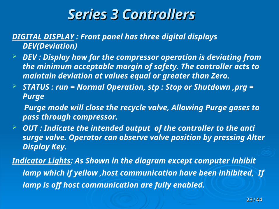
Series 3 ControllersSeries 3 Controllers DIGITAL DISPLAY : Front panel has three digital displays
DEV(Deviation) DEV : Display how far the compressor operation is deviating from
the minimum acceptable margin of safety. The controller acts to maintain deviation at values equal or greater than Zero.
STATUS : run = Normal Operation, stp : Stop or Shutdown ,prg = Purge
Purge mode will close the recycle valve, Allowing Purge gases to pass through compressor.
OUT : Indicate the intended output of the controller to the anti surge valve. Operator can observe valve position by pressing Alter Display Key.
Indicator Lights: As Shown in the diagram except computer inhibit
lamp which if yellow ,host communication have been inhibited, If
lamp is off host communication are fully enabled.

2424/44/44
Series 3 ControllersSeries 3 Controllers CONTROL KEYS : There are seven active control keys on the front
panel.
AUTO/MANUAL : Toggles the controller between the automatics & manual modes
INHIBIT/COMPUTER :Inhibits or enable certain type of communication(Can be Configured) with host computer or DCS.
</> (Up/Down) : Use to raise or lower the controller output signal when the manual operating mode is selected. Momentarily pressing ^ will increment output by .1 %.
RESET : Used to reset the Safety on response after a surge.It should only be pressed if the condition which caused the surge have been determined & corrected.
Display Surge Count : Upon pressing causes Status Display to show the no.of surge cycle the controller has recorded after the last reset.
Alternate Display: Temporally display certain results of the controller internal calculation. These keys can be pressed at any time without disturbing the process

2525/44/44
LabelLabel ColorColor Meaning Meaning What Can I doWhat Can I do
AutoAuto GreenGreen When lit, the controller is in the When lit, the controller is in the Automatic mode of OperationAutomatic mode of Operation
You can switch to the manual mode of You can switch to the manual mode of operation using the Auto/Manual switchoperation using the Auto/Manual switch
ManualManual YellowYellow When lit, the controller is in the Manual When lit, the controller is in the Manual Mode of Operation.Mode of Operation.
You can switch to the Automatic mode of You can switch to the Automatic mode of operation using the Auto/Manual Switch.operation using the Auto/Manual Switch.
RemoteRemote GreenGreen When lit, the Remote set point has been When lit, the Remote set point has been selected.selected.
You can select the local set point by You can select the local set point by using the Remote/Local switch if it has using the Remote/Local switch if it has been enabled.been enabled.
LocalLocal YellowYellow When lit, the local set point has been When lit, the local set point has been selected.selected.
When flashing, the load sharing When flashing, the load sharing Fallback has been enabled and the local Fallback has been enabled and the local set point has been selectedset point has been selected
If the local indicator is lit, you can select If the local indicator is lit, you can select the remote set point by using the the remote set point by using the Remote/Local switch if it has been Remote/Local switch if it has been enabled.enabled.
If the local indicator is flashing, then the If the local indicator is flashing, then the Fallback and ComErr indicators will be Fallback and ComErr indicators will be lit. Check the serial inputs.lit. Check the serial inputs.
Limit Limit YellowYellow When lit, the controller is in a limiting When lit, the controller is in a limiting condition because the Loop 2 and/or condition because the Loop 2 and/or Loop 3 limiting variables are beyond Loop 3 limiting variables are beyond their defined limiting threshold.their defined limiting threshold.
You can determine the value of the You can determine the value of the limiting variables by pressing the Display limiting variables by pressing the Display Loop 2 switch or the Display Loop 3 Loop 2 switch or the Display Loop 3 switch. If possible the process should be switch. If possible the process should be adjusted to prevent the limiting adjusted to prevent the limiting condition.condition.
Tracking Tracking GreenGreen When lit, the controller is in a redundant When lit, the controller is in a redundant operating mode and is tracking the operating mode and is tracking the active controller. When flashing, the active controller. When flashing, the output of the controller is being used as output of the controller is being used as a rotational speed set point and is a rotational speed set point and is tracking the speed.tracking the speed.
If the tracking indicator is lit, you can If the tracking indicator is lit, you can switch to the active operating mode by switch to the active operating mode by selecting this controller on the selecting this controller on the Redundant Control Selector. If the Redundant Control Selector. If the tracking indicator is flashing, then the tracking indicator is flashing, then the speed governor is either in manual or speed governor is either in manual or using a local set point.using a local set point.
2626/44/44
LabelLabel ColorColor Meaning Meaning What Can I doWhat Can I do
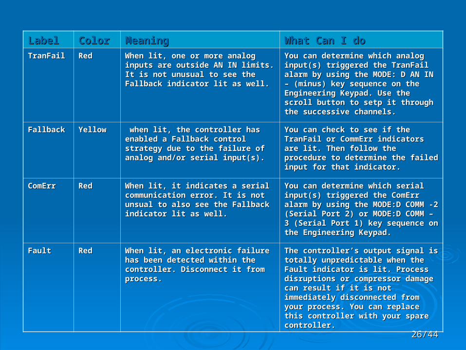
TranFailTranFail RedRed When lit, one or more analog inputs are When lit, one or more analog inputs are outside AN IN limits. It is not unusual to outside AN IN limits. It is not unusual to see the Fallback indicator lit as well.see the Fallback indicator lit as well.
You can determine which analog input(s) You can determine which analog input(s) triggered the TranFail alarm by using the triggered the TranFail alarm by using the MODE: D AN IN – (minus) key sequence MODE: D AN IN – (minus) key sequence on the Engineering Keypad. Use the on the Engineering Keypad. Use the scroll button to setp it through the scroll button to setp it through the successive channels.successive channels.
FallbackFallback YellowYellow when lit, the controller has enabled a when lit, the controller has enabled a Fallback control strategy due to the Fallback control strategy due to the failure of analog and/or serial input(s).failure of analog and/or serial input(s).
You can check to see if the TranFail or You can check to see if the TranFail or CommErr indicators are lit. Then follow CommErr indicators are lit. Then follow the procedure to determine the failed the procedure to determine the failed input for that indicator.input for that indicator.
ComErrComErr RedRed When lit, it indicates a serial When lit, it indicates a serial communication error. It is not unsual to communication error. It is not unsual to also see the Fallback indicator lit as also see the Fallback indicator lit as well.well.
You can determine which serial input(s) You can determine which serial input(s) triggered the ComErr alarm by using the triggered the ComErr alarm by using the MODE:D COMM -2 (Serial Port 2) or MODE:D COMM -2 (Serial Port 2) or MODE:D COMM – 3 (Serial Port 1) key MODE:D COMM – 3 (Serial Port 1) key sequence on the Engineering Keypad.sequence on the Engineering Keypad.
FaultFault RedRed When lit, an electronic failure has been When lit, an electronic failure has been detected within the controller. detected within the controller. Disconnect it from process.Disconnect it from process.
The controller’s output signal is totally The controller’s output signal is totally unpredictable when the Fault indicator is unpredictable when the Fault indicator is lit. Process disruptions or compressor lit. Process disruptions or compressor damage can result if it is not immediately damage can result if it is not immediately disconnected from your process. You disconnected from your process. You can replace this controller with your can replace this controller with your spare controller.spare controller.

2727/44/44
Series 3 ControllersSeries 3 Controllers Configuration ProcedureConfiguration Procedure : Catalog is to be referred. : Catalog is to be referred.Modes & Fall Back StrategiesModes & Fall Back Strategies : Series 3 Anti surge controller offers : Series 3 Anti surge controller offers
a wide variety of modes which allow you to tailor its surge a wide variety of modes which allow you to tailor its surge control algorithms to specific applications & no. of input s, control algorithms to specific applications & no. of input s, location of inputs like flow measurement at suction or location of inputs like flow measurement at suction or discharge, temp. measurement, pressure measurement, diff. discharge, temp. measurement, pressure measurement, diff. pressure measurement.pressure measurement.
In most applications , the more complicated algorithms will In most applications , the more complicated algorithms will provide energy savings as they tune controller more provide energy savings as they tune controller more aggressively.But because they require additional input signals, aggressively.But because they require additional input signals, so more complicated algorithms are also more likely to succumb so more complicated algorithms are also more likely to succumb to transmitter failures.to transmitter failures.
In many such cases it is feasible to provide continued In many such cases it is feasible to provide continued surge protection by substituting an approximate constant value surge protection by substituting an approximate constant value for the missing input. A fallback strategy defined will trigger the for the missing input. A fallback strategy defined will trigger the algorithms upon transmitter alarm condition.algorithms upon transmitter alarm condition.

2828/44/44
Series 3 ControllersSeries 3 Controllers Output Relay Output Relay : Series 3 Controllers comes with 4 relay (CR 0 to : Series 3 Controllers comes with 4 relay (CR 0 to
CR 3) which can be independently configured . These rely can CR 3) which can be independently configured . These rely can draw operator attention in the control room upon undesirable draw operator attention in the control room upon undesirable conditions.conditions.
CR 0 relay is normally configured as a fault relay, Other relay CR 0 relay is normally configured as a fault relay, Other relay can be configures for reporting Communication errors in the can be configures for reporting Communication errors in the Port 1 to 4, Safety ON, Auto/Manual mode,Operating Point to Port 1 to 4, Safety ON, Auto/Manual mode,Operating Point to the left of the recycle trip,Analog Input Out of the left of the recycle trip,Analog Input Out of range(Transmitter Failure).range(Transmitter Failure).
Other Series 3 Controller types: Other Series 3 Controller types: Performance ControllerPerformance Controller Dual Loop ControllersDual Loop Controllers Turbine Speed ControllerTurbine Speed Controller Fuel ControllerFuel Controller

2929/44/44
Salient features of Anti surge controllerSalient features of Anti surge controller
Output loop back test comparing actual output of Output loop back test comparing actual output of anti surge control loops with desired output, thus anti surge control loops with desired output, thus determining the failure status of the outputs.determining the failure status of the outputs.
Control loop decoupling among the performance Control loop decoupling among the performance and anti surge loops via serial port 1and anti surge loops via serial port 1
Serial communications for data and alarm Serial communications for data and alarm transfer to the DCS.transfer to the DCS.
ESD requestESD request Automated loading and unloading of the Automated loading and unloading of the
compressor train.compressor train. Fallback control strategiesFallback control strategies Limiting maximum discharge pressure / Limiting maximum discharge pressure /
minimum suction pressureminimum suction pressure

3030/44/44
Salient features of Anti surge controllerSalient features of Anti surge controller
Actuator output conditioningActuator output conditioning Valve flow characterisationValve flow characterisation Valve dead band compensationValve dead band compensation Output clampingOutput clamping Remote low output clampRemote low output clamp Tight shut off featureTight shut off feature Output reverse Output reverse Output trackingOutput tracking

3131
Over 75% of the problems are in the field and Over 75% of the problems are in the field and not in the controllernot in the controllerThe CCC control system has fall-back The CCC control system has fall-back strategies to handle these field problemsstrategies to handle these field problemsThe controller continuously monitors the The controller continuously monitors the validity of its inputsvalidity of its inputsIf an input problem is detected the controller If an input problem is detected the controller ignores this input and automatically switches ignores this input and automatically switches to a fall-back modeto a fall-back mode
Fallback stretegiesFallback stretegies

3232/44/44
Fallback stretegiesFallback stretegies Constant output : If the discharge flow Constant output : If the discharge flow
measurement fails, the antisurge valve opening will measurement fails, the antisurge valve opening will be frozen -implemented in Cokerbe frozen -implemented in Coker
Minimum flow control : when flow measurement is Minimum flow control : when flow measurement is reliable but others are not, surge is prevented by reliable but others are not, surge is prevented by maintaining minimum flow - implemented in Cokermaintaining minimum flow - implemented in Coker
Default compression ratio : The controller can Default compression ratio : The controller can substitute a default compression ratio if the substitute a default compression ratio if the discharge pressure input fail, 1discharge pressure input fail, 1stst stage = 4,89; 2 stage = 4,89; 2ndnd stage =4.18 - implemented in Cokerstage =4.18 - implemented in Coker
Assumed sigma : if either of the temperature inputs Assumed sigma : if either of the temperature inputs fail, surge is protected by substituting a constant fail, surge is protected by substituting a constant value for sigma - implemented in Cokervalue for sigma - implemented in Coker

3333/44/44
Other Fallback strategiesOther Fallback strategies (not implemented in Coker)(not implemented in Coker)
Assumed speedAssumed speed Assumed vane angleAssumed vane angle Assumed adjacent stage flow rateAssumed adjacent stage flow rate Temperature based polytropic headTemperature based polytropic head A second anti surge controller as on line A second anti surge controller as on line
back upback up
3434/44/44
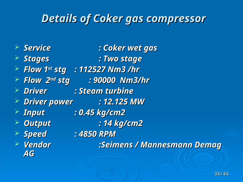
Details of Coker gas compressorDetails of Coker gas compressor
ServiceService : Coker wet gas : Coker wet gas StagesStages : Two stage : Two stage Flow 1Flow 1stst stg stg : 112527 Nm3 /hr : 112527 Nm3 /hr Flow 2Flow 2ndnd stg : 90000 Nm3/hr stg : 90000 Nm3/hr DriverDriver : Steam turbine : Steam turbine Driver powerDriver power : : 12.125 MW12.125 MW InputInput : 0.45 kg/cm2 : 0.45 kg/cm2 OutputOutput : 14 kg/cm2 : 14 kg/cm2 SpeedSpeed : 4850 RPM : 4850 RPM VendorVendor :Seimens / Mannesmann Demag :Seimens / Mannesmann Demag
AGAG
3535/44/44
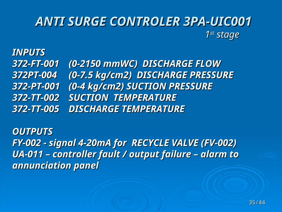
ANTI SURGE CONTROLER 3PA-UIC001ANTI SURGE CONTROLER 3PA-UIC00111stst stage stage
INPUTSINPUTS372-FT-001372-FT-001 (0-2150 mmWC) DISCHARGE FLOW(0-2150 mmWC) DISCHARGE FLOW372PT-004372PT-004 (0-7.5 kg/cm2) DISCHARGE PRESSURE(0-7.5 kg/cm2) DISCHARGE PRESSURE372-PT-001372-PT-001 (0-4 kg/cm2) SUCTION PRESSURE (0-4 kg/cm2) SUCTION PRESSURE 372-TT-002372-TT-002 SUCTION TEMPERATURESUCTION TEMPERATURE372-TT-005372-TT-005 DISCHARGE TEMPERATUREDISCHARGE TEMPERATURE
OUTPUTSOUTPUTSFY-002 - signal 4-20mA for RECYCLE VALVE (FV-002)FY-002 - signal 4-20mA for RECYCLE VALVE (FV-002)UA-011 – controller fault / output failure – alarm to UA-011 – controller fault / output failure – alarm to annunciation panelannunciation panel
3636/44/44
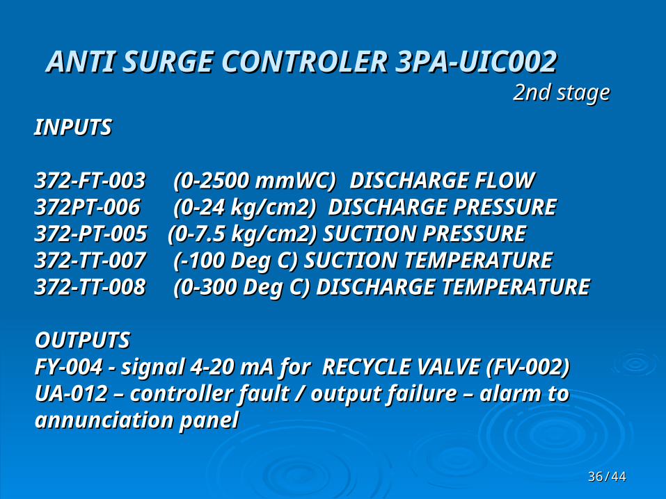
ANTI SURGE CONTROLER 3PA-UIC002ANTI SURGE CONTROLER 3PA-UIC0022nd stage2nd stage
INPUTSINPUTS
372-FT-003372-FT-003 (0-2500 mmWC) (0-2500 mmWC) DISCHARGE FLOWDISCHARGE FLOW372PT-006372PT-006 (0-24 kg/cm2) DISCHARGE PRESSURE (0-24 kg/cm2) DISCHARGE PRESSURE372-PT-005372-PT-005 (0-7.5 kg/cm2) SUCTION PRESSURE (0-7.5 kg/cm2) SUCTION PRESSURE 372-TT-007372-TT-007 (-100 Deg C) SUCTION TEMPERATURE (-100 Deg C) SUCTION TEMPERATURE372-TT-008372-TT-008 (0-300 Deg C) DISCHARGE TEMPERATURE (0-300 Deg C) DISCHARGE TEMPERATURE
OUTPUTSOUTPUTSFY-004 - signal 4-20 mA for RECYCLE VALVE (FV-002)FY-004 - signal 4-20 mA for RECYCLE VALVE (FV-002)UA-012 – controller fault / output failure – alarm to UA-012 – controller fault / output failure – alarm to annunciation panelannunciation panel

3737/44/44
Serial links/ interfacesSerial links/ interfaces
11stst Stage Stage Pressure override control from performance controllerPressure override control from performance controller Communication with DCS (MG07)Communication with DCS (MG07) Decoupling with performance and second stage anti surge controllerDecoupling with performance and second stage anti surge controller
22ndnd Stage Stage Communication with DCS (MG07)Communication with DCS (MG07) Decoupling with performance and 1st stage anti surge controllerDecoupling with performance and 1st stage anti surge controller
Fractionator's top pressure control with 1st stage anti surge controllerFractionator's top pressure control with 1st stage anti surge controllerOutput of 371PIC001 from DCS is given as remote low clamp Output of 371PIC001 from DCS is given as remote low clamp (4 to 20 mA signal) to the 1st stage anti-surge controller (4 to 20 mA signal) to the 1st stage anti-surge controller
3838/44/44
HOW CONTROLLER KNOWS THE HOW CONTROLLER KNOWS THE SURGE LINE ?SURGE LINE ?
SURGE TEST …SURGE TEST …
3939/44/44
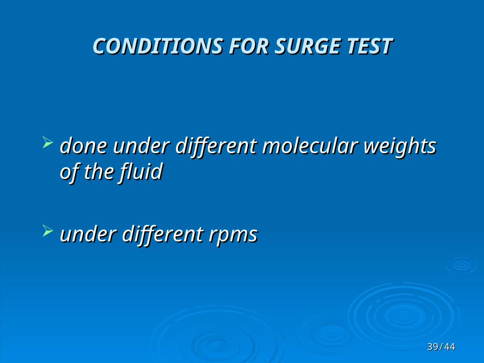
CONDITIONS FOR SURGE TESTCONDITIONS FOR SURGE TEST
done under different molecular weights done under different molecular weights of the fluidof the fluid
under different rpms under different rpms

4040/44/44
REASON FOR THE CONDITIONSREASON FOR THE CONDITIONS
The compressor compresses recycle gas from The compressor compresses recycle gas from the start of run to the end of run conditionsthe start of run to the end of run conditions
The recycle gas undergoes change in the The recycle gas undergoes change in the composition during the runcomposition during the run
As the compressor has to be under the safety As the compressor has to be under the safety limit under all the conditions ,the surge test is limit under all the conditions ,the surge test is done under different molecular weights and done under different molecular weights and different rpmsdifferent rpms
4141/44/44
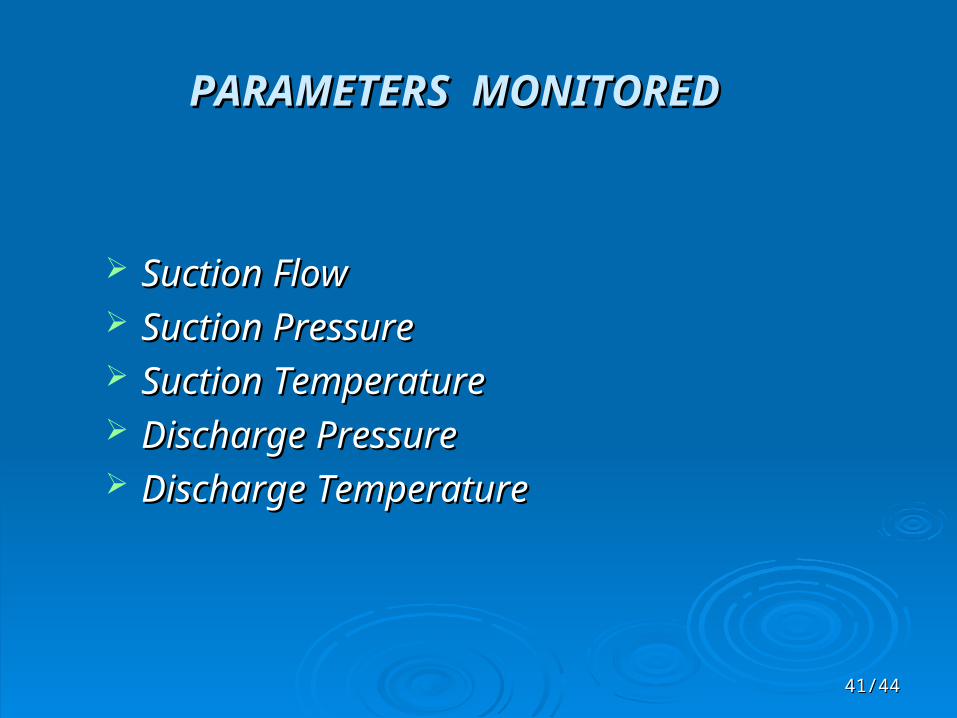
PARAMETERS MONITOREDPARAMETERS MONITORED
Suction FlowSuction Flow Suction PressureSuction Pressure Suction TemperatureSuction Temperature Discharge PressureDischarge Pressure Discharge TemperatureDischarge Temperature

4242/44/44
b1 b2
SOL SLL RTL SCL New SCLAfter SO
Operating Point
Pressure:
HpRc Pd ∆Pc
Flow: Q, Q2, kW, ∆Po
Rt
COMPRESSOR SURGE CONTROL MAP

4343/44/44
Surge test Steps …Surge test Steps …1.1. Reduce the flow somewhat through the compressor with anti surge valve Reduce the flow somewhat through the compressor with anti surge valve
closedclosed2.2. Hold the compressor at minimum performance level – minimum speedHold the compressor at minimum performance level – minimum speed3.3. Put the anti surge controller in manual and open the recycle valve 100%Put the anti surge controller in manual and open the recycle valve 100%4.4. If possible, isolate the compressor with a discharge block valveIf possible, isolate the compressor with a discharge block valve5.5. Disable derivative response - opening of recycle valve will be constant on Disable derivative response - opening of recycle valve will be constant on
Recycle Trip and no shifting of Surge Control LineRecycle Trip and no shifting of Surge Control Line6.6. Disable fall back strategyDisable fall back strategy7.7. Put b1 =0 , now SCL will be on the top of SLLPut b1 =0 , now SCL will be on the top of SLL8.8. Put b2 =40, to ensure large Margin of Safety on Safety On responsePut b2 =40, to ensure large Margin of Safety on Safety On response9.9. Put RT=5 & SO= 10 to put RTL & SOL just to the left of SCL /SLLPut RT=5 & SO= 10 to put RTL & SOL just to the left of SCL /SLL10.10. Put C1=30 & C2= 0.4 to open recycle valve 30% for 0.4 secPut C1=30 & C2= 0.4 to open recycle valve 30% for 0.4 sec11.11. Put TL =200 recycle valve closure time for 63% closing Put TL =200 recycle valve closure time for 63% closing 12.12. Put PI tuning constants to average conservative valuesPut PI tuning constants to average conservative values13.13. Put K= .999 this moves SCL & SLL to right as far as possiblePut K= .999 this moves SCL & SLL to right as far as possible14.14. Put controller in auto. DEViation will be +ve, valve will close, DEV will be 0Put controller in auto. DEViation will be +ve, valve will close, DEV will be 015.15. Reduce K by 0.01, DEV again will be +ve, valve will close and DEV will be 0Reduce K by 0.01, DEV again will be +ve, valve will close and DEV will be 016.16. Repeat step 15 till K value will correspond to actual SLL location, then drop in Repeat step 15 till K value will correspond to actual SLL location, then drop in DEV will result in RT (crossing of RT & SOL line), valve will open , RT line will DEV will result in RT (crossing of RT & SOL line), valve will open , RT line will shift 40% -- this is the point surge has occurredshift 40% -- this is the point surge has occurred17. Put the controller in manual , open the valve 100%, note the value of K 17. Put the controller in manual , open the valve 100%, note the value of K

4444/44/44
Thank you
?


![Antisurge Controller forAxial & Centrifugal Compressors [CCC Book].pdf](https://static.fdocuments.in/doc/165x107/552f2fc14a7959b7628b4aae/antisurge-controller-foraxial-centrifugal-compressors-ccc-bookpdf.jpg)