Anti-Lock Braking Systems (ABS) for Trucks, …...Anti-Lock Braking Systems (ABS) for Trucks,...
43
Anti-Lock Braking Systems (ABS) for Trucks,Tractors and Buses Maintenance Manual No. 28 Revised 4-98 • For C Version ECUs
Transcript of Anti-Lock Braking Systems (ABS) for Trucks, …...Anti-Lock Braking Systems (ABS) for Trucks,...
Anti-Lock Braking Systems (ABS) for Trucks, Tractors and Buses
Maintenance Manual No. 28Revised 4-98
• For C Version ECUs
mm28new.fm Page -3 Tuesday, February 5, 2002 9:26 AM
Copyright 1998 Meritor WABCO
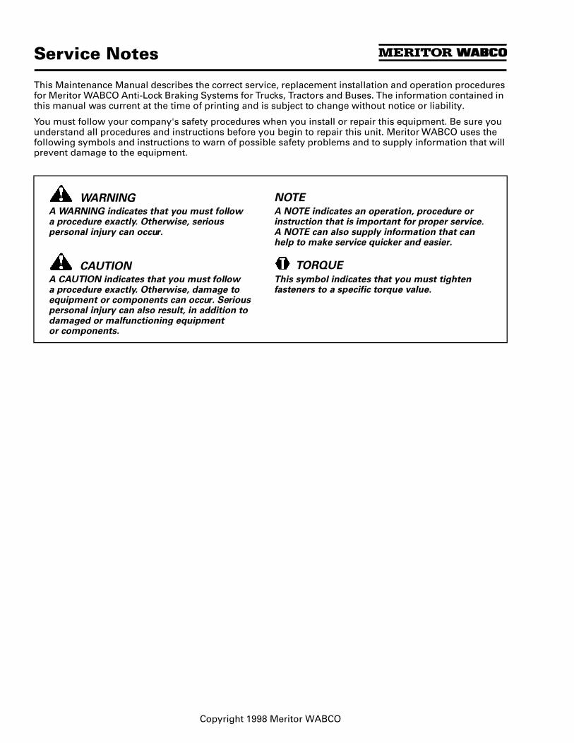
Service Notes
This Maintenance Manual describes the correct service, replacement installation and operation procedures for Meritor WABCO Anti-Lock Braking Systems for Trucks, Tractors and Buses. The information contained in this manual was current at the time of printing and is subject to change without notice or liability.
You must follow your company's safety procedures when you install or repair this equipment. Be sure you understand all procedures and instructions before you begin to repair this unit. Meritor WABCO uses the following symbols and instructions to warn of possible safety problems and to supply information that will prevent damage to the equipment.
WARNINGA WARNING indicates that you must follow a procedure exactly. Otherwise, serious personal injury can occur.
CAUTIONA CAUTION indicates that you must follow a procedure exactly. Otherwise, damage to equipment or components can occur. Serious personal injury can also result, in addition to damaged or malfunctioning equipment or components.
NOTEA NOTE indicates an operation, procedure or instruction that is important for proper service. A NOTE can also supply information that can help to make service quicker and easier.
TORQUE
This symbol indicates that you must tighten fasteners to a specific torque value.
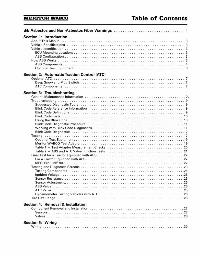
Table of Contents
Asbestos and Non-Asbestos Fiber Warnings . . . . . . . . . . . . . . . . . . . . . . . . . . . . . . . . . . . . . . . 1
Section 1: Introduction About This Manual . . . . . . . . . . . . . . . . . . . . . . . . . . . . . . . . . . . . . . . . . . . . . . . . . . . . . . . . . . . . . . . . . . . . .3Vehicle Specifications . . . . . . . . . . . . . . . . . . . . . . . . . . . . . . . . . . . . . . . . . . . . . . . . . . . . . . . . . . . . . . . . . .3Vehicle Identification . . . . . . . . . . . . . . . . . . . . . . . . . . . . . . . . . . . . . . . . . . . . . . . . . . . . . . . . . . . . . . . . . . .3
ECU Mounting Locations . . . . . . . . . . . . . . . . . . . . . . . . . . . . . . . . . . . . . . . . . . . . . . . . . . . . . . . . . . . . . .3ABS Configuration . . . . . . . . . . . . . . . . . . . . . . . . . . . . . . . . . . . . . . . . . . . . . . . . . . . . . . . . . . . . . . . . . . .3
How ABS Works . . . . . . . . . . . . . . . . . . . . . . . . . . . . . . . . . . . . . . . . . . . . . . . . . . . . . . . . . . . . . . . . . . . . . . .3ABS Components . . . . . . . . . . . . . . . . . . . . . . . . . . . . . . . . . . . . . . . . . . . . . . . . . . . . . . . . . . . . . . . . . . . .4Optional Test Equipment . . . . . . . . . . . . . . . . . . . . . . . . . . . . . . . . . . . . . . . . . . . . . . . . . . . . . . . . . . . . . .6
Section 2: Automatic Traction Control (ATC) Optional ATC . . . . . . . . . . . . . . . . . . . . . . . . . . . . . . . . . . . . . . . . . . . . . . . . . . . . . . . . . . . . . . . . . . . . . . . . .7
Deep Snow and Mud Switch . . . . . . . . . . . . . . . . . . . . . . . . . . . . . . . . . . . . . . . . . . . . . . . . . . . . . . . . . . .7ATC Components . . . . . . . . . . . . . . . . . . . . . . . . . . . . . . . . . . . . . . . . . . . . . . . . . . . . . . . . . . . . . . . . . . . .7
Section 3: Troubleshooting General Maintenance Information . . . . . . . . . . . . . . . . . . . . . . . . . . . . . . . . . . . . . . . . . . . . . . . . . . . . . . . .9Troubleshooting . . . . . . . . . . . . . . . . . . . . . . . . . . . . . . . . . . . . . . . . . . . . . . . . . . . . . . . . . . . . . . . . . . . . . . .9
Suggested Diagnostic Tools . . . . . . . . . . . . . . . . . . . . . . . . . . . . . . . . . . . . . . . . . . . . . . . . . . . . . . . . . . .9Blink Code Reference Information . . . . . . . . . . . . . . . . . . . . . . . . . . . . . . . . . . . . . . . . . . . . . . . . . . . . . .9Blink Code Definitions . . . . . . . . . . . . . . . . . . . . . . . . . . . . . . . . . . . . . . . . . . . . . . . . . . . . . . . . . . . . . . . .9Blink Code Facts . . . . . . . . . . . . . . . . . . . . . . . . . . . . . . . . . . . . . . . . . . . . . . . . . . . . . . . . . . . . . . . . . . . .10Using the Blink Code . . . . . . . . . . . . . . . . . . . . . . . . . . . . . . . . . . . . . . . . . . . . . . . . . . . . . . . . . . . . . . . .10Blink Code Diagnostic Procedure . . . . . . . . . . . . . . . . . . . . . . . . . . . . . . . . . . . . . . . . . . . . . . . . . . . . . .11Working with Blink Code Diagnostics. . . . . . . . . . . . . . . . . . . . . . . . . . . . . . . . . . . . . . . . . . . . . . . . . . .11Blink Code Diagnostics. . . . . . . . . . . . . . . . . . . . . . . . . . . . . . . . . . . . . . . . . . . . . . . . . . . . . . . . . . . . . . .12
Testing . . . . . . . . . . . . . . . . . . . . . . . . . . . . . . . . . . . . . . . . . . . . . . . . . . . . . . . . . . . . . . . . . . . . . . . . . . . . . 17Optional Test Equipment . . . . . . . . . . . . . . . . . . . . . . . . . . . . . . . . . . . . . . . . . . . . . . . . . . . . . . . . . . . . .19Meritor WABCO Test Adaptor . . . . . . . . . . . . . . . . . . . . . . . . . . . . . . . . . . . . . . . . . . . . . . . . . . . . . . . . .19Table 1 — Test Adaptor Measurement Checks . . . . . . . . . . . . . . . . . . . . . . . . . . . . . . . . . . . . . . . . . . .20Table 2 — ABS and ATC Valve Function Tests . . . . . . . . . . . . . . . . . . . . . . . . . . . . . . . . . . . . . . . . . . .21
Final Test for a Tractor Equipped with ABS . . . . . . . . . . . . . . . . . . . . . . . . . . . . . . . . . . . . . . . . . . . . . . . .22For a Tractor Equipped with ABS . . . . . . . . . . . . . . . . . . . . . . . . . . . . . . . . . . . . . . . . . . . . . . . . . . . . . .22MPSI Pro-Link® 9000 . . . . . . . . . . . . . . . . . . . . . . . . . . . . . . . . . . . . . . . . . . . . . . . . . . . . . . . . . . . . . . . . .22
Testing and Diagnostic Screens . . . . . . . . . . . . . . . . . . . . . . . . . . . . . . . . . . . . . . . . . . . . . . . . . . . . . . . . .23Testing Components . . . . . . . . . . . . . . . . . . . . . . . . . . . . . . . . . . . . . . . . . . . . . . . . . . . . . . . . . . . . . . . .24Ignition Voltage. . . . . . . . . . . . . . . . . . . . . . . . . . . . . . . . . . . . . . . . . . . . . . . . . . . . . . . . . . . . . . . . . . . . .25Sensor Resistance . . . . . . . . . . . . . . . . . . . . . . . . . . . . . . . . . . . . . . . . . . . . . . . . . . . . . . . . . . . . . . . . . .25Sensor Adjustment. . . . . . . . . . . . . . . . . . . . . . . . . . . . . . . . . . . . . . . . . . . . . . . . . . . . . . . . . . . . . . . . . .25ABS Valve . . . . . . . . . . . . . . . . . . . . . . . . . . . . . . . . . . . . . . . . . . . . . . . . . . . . . . . . . . . . . . . . . . . . . . . . .25ATC Valve . . . . . . . . . . . . . . . . . . . . . . . . . . . . . . . . . . . . . . . . . . . . . . . . . . . . . . . . . . . . . . . . . . . . . . . . .25Dynamometer Testing Vehicles with ATC . . . . . . . . . . . . . . . . . . . . . . . . . . . . . . . . . . . . . . . . . . . . . . .26
Tire Size Range . . . . . . . . . . . . . . . . . . . . . . . . . . . . . . . . . . . . . . . . . . . . . . . . . . . . . . . . . . . . . . . . . . . . . . .26
Section 4: Removal & Installation Component Removal and Installation . . . . . . . . . . . . . . . . . . . . . . . . . . . . . . . . . . . . . . . . . . . . . . . . . . . . 27
Sensors . . . . . . . . . . . . . . . . . . . . . . . . . . . . . . . . . . . . . . . . . . . . . . . . . . . . . . . . . . . . . . . . . . . . . . . . . . .27Valves . . . . . . . . . . . . . . . . . . . . . . . . . . . . . . . . . . . . . . . . . . . . . . . . . . . . . . . . . . . . . . . . . . . . . . . . . . . .28
Section 5: Wiring Wiring . . . . . . . . . . . . . . . . . . . . . . . . . . . . . . . . . . . . . . . . . . . . . . . . . . . . . . . . . . . . . . . . . . . . . . . . . . . . . .30
Page 1
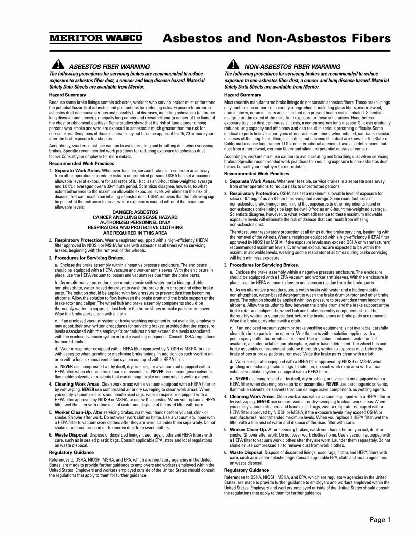
Asbestos and Non-Asbestos Fibers
ASBESTOS FIBER WARNINGThe following procedures for servicing brakes are recommended to reduce exposure to asbestos fiber dust, a cancer and lung disease hazard. Material Safety Data Sheets are available from Meritor.Hazard Summary
Because some brake linings contain asbestos, workers who service brakes must understand the potential hazards of asbestos and precautions for reducing risks. Exposure to airborne asbestos dust can cause serious and possibly fatal diseases, including asbestosis (a chronic lung disease) and cancer, principally lung cancer and mesothelioma (a cancer of the lining of the chest or abdominal cavities). Some studies show that the risk of lung cancer among persons who smoke and who are exposed to asbestos is much greater than the risk for non-smokers. Symptoms of these diseases may not become apparent for 15, 20 or more years after the first exposure to asbestos.Accordingly, workers must use caution to avoid creating and breathing dust when servicing brakes. Specific recommended work practices for reducing exposure to asbestos dust follow. Consult your employer for more details.Recommended Work Practices
1. Separate Work Areas. Whenever feasible, service brakes in a separate area away from other operations to reduce risks to unprotected persons. OSHA has set a maximum allowable level of exposure for asbestos of 0.1 f/cc as an 8-hour time-weighted average and 1.0 f/cc averaged over a 30-minute period. Scientists disagree, however, to what extent adherence to the maximum allowable exposure levels will eliminate the risk of disease that can result from inhaling asbestos dust. OSHA requires that the following sign be posted at the entrance to areas where exposures exceed either of the maximum allowable levels:
DANGER: ASBESTOSCANCER AND LUNG DISEASE HAZARD
AUTHORIZED PERSONNEL ONLYRESPIRATORS AND PROTECTIVE CLOTHING
ARE REQUIRED IN THIS AREA
2. Respiratory Protection. Wear a respirator equipped with a high-efficiency (HEPA) filter approved by NIOSH or MSHA for use with asbestos at all times when servicing brakes, beginning with the removal of the wheels.
3. Procedures for Servicing Brakes.
a. Enclose the brake assembly within a negative pressure enclosure. The enclosure should be equipped with a HEPA vacuum and worker arm sleeves. With the enclosure in place, use the HEPA vacuum to loosen and vacuum residue from the brake parts.b. As an alternative procedure, use a catch basin with water and a biodegradable,non-phosphate, water-based detergent to wash the brake drum or rotor and other brake parts. The solution should be applied with low pressure to prevent dust from becoming airborne. Allow the solution to flow between the brake drum and the brake support or the brake rotor and caliper. The wheel hub and brake assembly components should be thoroughly wetted to suppress dust before the brake shoes or brake pads are removed. Wipe the brake parts clean with a cloth.c. If an enclosed vacuum system or brake washing equipment is not available, employers may adopt their own written procedures for servicing brakes, provided that the exposure levels associated with the employer's procedures do not exceed the levels associated with the enclosed vacuum system or brake washing equipment. Consult OSHA regulations for more details.d. Wear a respirator equipped with a HEPA filter approved by NIOSH or MSHA for use with asbestos when grinding or machining brake linings. In addition, do such work in an area with a local exhaust ventilation system equipped with a HEPA filter.e. NEVER use compressed air by itself, dry brushing, or a vacuum not equipped with a HEPA filter when cleaning brake parts or assemblies. NEVER use carcinogenic solvents, flammable solvents, or solvents that can damage brake components as wetting agents.
4. Cleaning Work Areas. Clean work areas with a vacuum equipped with a HEPA filter or by wet wiping. NEVER use compressed air or dry sweeping to clean work areas. When you empty vacuum cleaners and handle used rags, wear a respirator equipped with a HEPA filter approved by NIOSH or MSHA for use with asbestos. When you replace a HEPA filter, wet the filter with a fine mist of water and dispose of the used filter with care.
5. Worker Clean-Up. After servicing brakes, wash your hands before you eat, drink or smoke. Shower after work. Do not wear work clothes home. Use a vacuum equipped with a HEPA filter to vacuum work clothes after they are worn. Launder them separately. Do not shake or use compressed air to remove dust from work clothes.
6. Waste Disposal. Dispose of discarded linings, used rags, cloths and HEPA filters with care, such as in sealed plastic bags. Consult applicable EPA, state and local regulations on waste disposal.
Regulatory Guidance
References to OSHA, NIOSH, MSHA, and EPA, which are regulatory agencies in the United States, are made to provide further guidance to employers and workers employed within the United States. Employers and workers employed outside of the United States should consult the regulations that apply to them for further guidance.
NON-ASBESTOS FIBER WARNINGThe following procedures for servicing brakes are recommended to reduce exposure to non-asbestos fiber dust, a cancer and lung disease hazard. Material Safety Data Sheets are available from Meritor. Hazard Summary
Most recently manufactured brake linings do not contain asbestos fibers. These brake linings may contain one or more of a variety of ingredients, including glass fibers, mineral wool, aramid fibers, ceramic fibers and silica that can present health risks if inhaled. Scientists disagree on the extent of the risks from exposure to these substances. Nonetheless, exposure to silica dust can cause silicosis, a non-cancerous lung disease. Silicosis gradually reduces lung capacity and efficiency and can result in serious breathing difficulty. Some medical experts believe other types of non-asbestos fibers, when inhaled, can cause similar diseases of the lung. In addition, silica dust and ceramic fiber dust are known to the State of California to cause lung cancer. U.S. and international agencies have also determined that dust from mineral wool, ceramic fibers and silica are potential causes of cancer.Accordingly, workers must use caution to avoid creating and breathing dust when servicing brakes. Specific recommended work practices for reducing exposure to non-asbestos dust follow. Consult your employer for more details.Recommended Work Practices
1. Separate Work Areas. Whenever feasible, service brakes in a separate area away from other operations to reduce risks to unprotected persons.
2. Respiratory Protection. OSHA has set a maximum allowable level of exposure for silica of 0.1 mg/m3 as an 8-hour time-weighted average. Some manufacturers of non-asbestos brake linings recommend that exposures to other ingredients found in non-asbestos brake linings be kept below 1.0 f/cc as an 8-hour time-weighted average. Scientists disagree, however, to what extent adherence to these maximum allowable exposure levels will eliminate the risk of disease that can result from inhalingnon-asbestos dust.Therefore, wear respiratory protection at all times during brake servicing, beginning with the removal of the wheels. Wear a respirator equipped with a high-efficiency (HEPA) filter approved by NIOSH or MSHA, if the exposure levels may exceed OSHA or manufacturers' recommended maximum levels. Even when exposures are expected to be within the maximum allowable levels, wearing such a respirator at all times during brake servicing will help minimize exposure.
3. Procedures for Servicing Brakes.
a. Enclose the brake assembly within a negative pressure enclosure. The enclosure should be equipped with a HEPA vacuum and worker arm sleeves. With the enclosure in place, use the HEPA vacuum to loosen and vacuum residue from the brake parts.b. As an alternative procedure, use a catch basin with water and a biodegradable, non-phosphate, water-based detergent to wash the brake drum or rotor and other brake parts. The solution should be applied with low pressure to prevent dust from becoming airborne. Allow the solution to flow between the brake drum and the brake support or the brake rotor and caliper. The wheel hub and brake assembly components should be thoroughly wetted to suppress dust before the brake shoes or brake pads are removed. Wipe the brake parts clean with a cloth.c. If an enclosed vacuum system or brake washing equipment is not available, carefully clean the brake parts in the open air. Wet the parts with a solution applied with a pump-spray bottle that creates a fine mist. Use a solution containing water, and, if available, a biodegradable, non-phosphate, water-based detergent. The wheel hub and brake assembly components should be thoroughly wetted to suppress dust before the brake shoes or brake pads are removed. Wipe the brake parts clean with a cloth.d. Wear a respirator equipped with a HEPA filter approved by NIOSH or MSHA when grinding or machining brake linings. In addition, do such work in an area with a local exhaust ventilation system equipped with a HEPA filter.e. NEVER use compressed air by itself, dry brushing, or a vacuum not equipped with a HEPA filter when cleaning brake parts or assemblies. NEVER use carcinogenic solvents, flammable solvents, or solvents that can damage brake components as wetting agents.
4. Cleaning Work Areas. Clean work areas with a vacuum equipped with a HEPA filter or by wet wiping. NEVER use compressed air or dry sweeping to clean work areas. When you empty vacuum cleaners and handle used rags, wear a respirator equipped with a HEPA filter approved by NIOSH or MSHA, if the exposure levels may exceed OSHA or manufacturers' recommended maximum levels. When you replace a HEPA filter, wet the filter with a fine mist of water and dispose of the used filter with care.
5. Worker Clean-Up. After servicing brakes, wash your hands before you eat, drink or smoke. Shower after work. Do not wear work clothes home. Use a vacuum equipped with a HEPA filter to vacuum work clothes after they are worn. Launder them separately. Do not shake or use compressed air to remove dust from work clothes.
6. Waste Disposal. Dispose of discarded linings, used rags, cloths and HEPA filters with care, such as in sealed plastic bags. Consult applicable EPA, state and local regulations on waste disposal.
Regulatory Guidance
References to OSHA, NIOSH, MSHA, and EPA, which are regulatory agencies in the United States, are made to provide further guidance to employers and workers employed within the United States. Employers and workers employed outside of the United States should consult the regulations that apply to them for further guidance.

Notes
Page 2
Page 3
Section 1Introduction
Section 1Introduction
About This Manual
This manual contains service, troubleshooting, and repair information for the Meritor WABCO Anti-Lock Braking System (ABS) and ABS with Automatic Traction Control (ATC) for trucks, tractors, and buses manufactured after December 1990. If your ABS-equipped vehicle was manufactured before this date, call Meritor WABCO customer service, 800-535-5560, for assistance.
Vehicle Specifications
To use this manual you need the following information about your vehicle:
O Where is the ECU mounted?
O How is the ABS configured?
O What are the tire sizes used on the vehicle? (See Section 3, "Troubleshooting".)
O Is it equipped with ATC? (See Section 2, “Automatic Traction Control [ATC]”.)
O Use the chart shown in Table A to record vehicle identification data.
Vehicle Identification
ECU Mounting Locations
The Electronic Control Unit (ECU) may be mounted in the cab or on the frame of the vehicle.
ABS Configuration
The ABS configuration is determined by the number of wheel end sensors and modulator valves. There are three possibilities:
O 4 wheel end sensors, 4 modulator valves (4S/4M)
O 6 wheel end sensors, 4 modulator valves (6S/4M)
O 6 wheel end sensors, 6 modulator valves (6S/6M)
Typical ABS configurations are illustrated in Section 3, "Troubleshooting", Figures 3.4–3.9.
How ABS WorksThe Meritor WABCO Anti-Lock Braking System (ABS) is an electronic system that monitors and controls wheel speed during braking. The system works with standard air brake systems.The ABS monitors wheel speed at all times and controls braking during emergency situations. The Meritor WABCO ABS improves vehicle stability and control by reducing wheel lock during braking.
In the unlikely event of a malfunction in the system, the ECU will disable all or only a portion of the ABS, returning the affected wheels to normal braking.An electronic control unit (ECU) receives and processes signals from the wheel speed sensors. When the ECU determines a wheel lockup condition, the unit activates an appropriate modulator valve, and air pressure is reduced. When the wheel speed enters the stable region again, the pressure is automatically increased.There is an ABS warning lamp to let the driver — and the service technician — know the system is working. ABS warning lamps for systems installed on buses, trucks, or tractors are located on the dash or instrument panel, depending on the make and model of the vehicle.
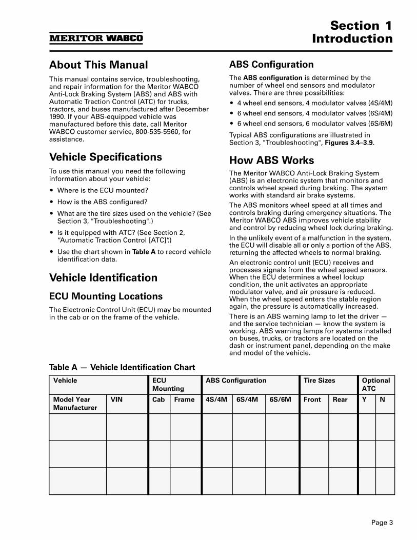
Table A — Vehicle Identification Chart
Vehicle ECU
Mounting
ABS Configuration Tire Sizes Optional
ATC
Model Year
Manufacturer
VIN Cab Frame 4S/4M 6S/4M 6S/6M Front Rear Y N
Section 1Introduction
Page 4
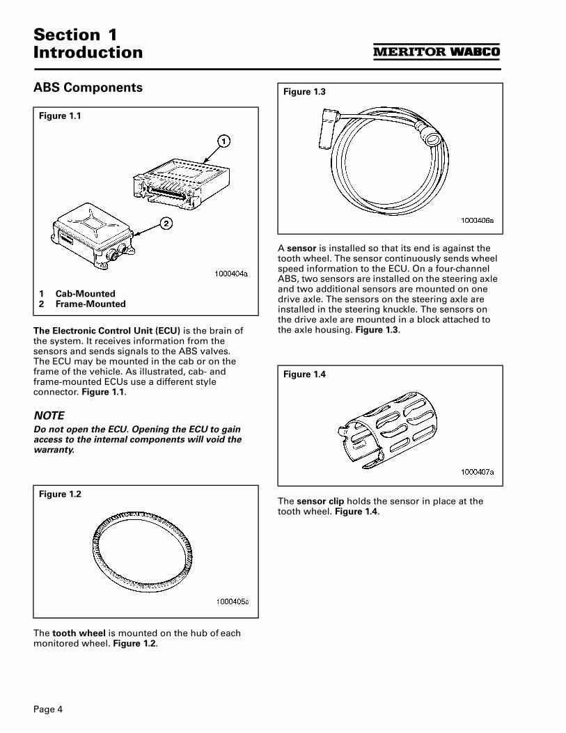
ABS Components
The Electronic Control Unit (ECU) is the brain of the system. It receives information from the sensors and sends signals to the ABS valves.The ECU may be mounted in the cab or on the frame of the vehicle. As illustrated, cab- andframe-mounted ECUs use a different style connector. Figure 1.1.
NOTEDo not open the ECU. Opening the ECU to gain access to the internal components will void the warranty.
The tooth wheel is mounted on the hub of each monitored wheel. Figure 1.2.
A sensor is installed so that its end is against the tooth wheel. The sensor continuously sends wheel speed information to the ECU. On a four-channel ABS, two sensors are installed on the steering axle and two additional sensors are mounted on one drive axle. The sensors on the steering axle are installed in the steering knuckle. The sensors on the drive axle are mounted in a block attached to the axle housing. Figure 1.3.
The sensor clip holds the sensor in place at the tooth wheel. Figure 1.4.
Figure 1.1
1 Cab-Mounted2 Frame-Mounted
Figure 1.2
Figure 1.3
Figure 1.4
Page 5
Section 1Introduction
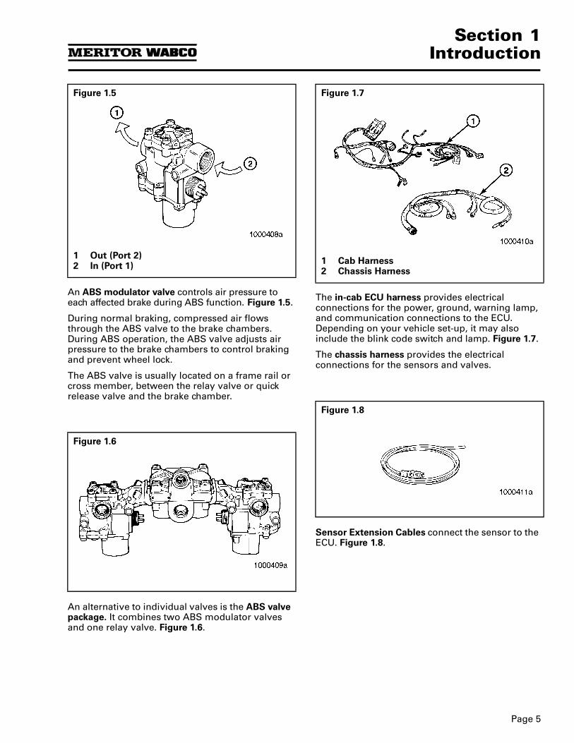
An ABS modulator valve controls air pressure to each affected brake during ABS function. Figure 1.5.
During normal braking, compressed air flows through the ABS valve to the brake chambers. During ABS operation, the ABS valve adjusts air pressure to the brake chambers to control braking and prevent wheel lock.
The ABS valve is usually located on a frame rail or cross member, between the relay valve or quick release valve and the brake chamber.
An alternative to individual valves is the ABS valve package. It combines two ABS modulator valves and one relay valve. Figure 1.6.
The in-cab ECU harness provides electrical connections for the power, ground, warning lamp, and communication connections to the ECU. Depending on your vehicle set-up, it may also include the blink code switch and lamp. Figure 1.7.
The chassis harness provides the electrical connections for the sensors and valves.
Sensor Extension Cables connect the sensor to the ECU. Figure 1.8.
Figure 1.5
1 Out (Port 2)2 In (Port 1)
Figure 1.6
Figure 1.7
1 Cab Harness2 Chassis Harness
Figure 1.8
Section 1Introduction
Page 6
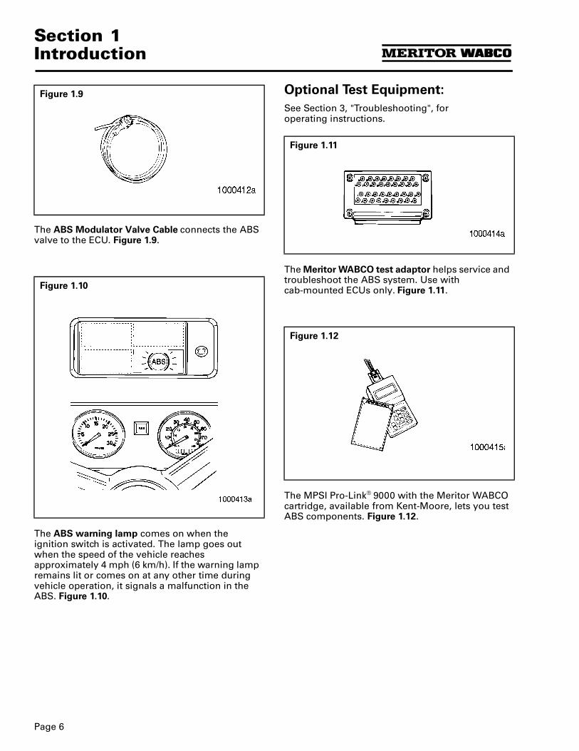
The ABS Modulator Valve Cable connects the ABS valve to the ECU. Figure 1.9.
The ABS warning lamp comes on when the ignition switch is activated. The lamp goes out when the speed of the vehicle reaches approximately 4 mph (6 km/h). If the warning lamp remains lit or comes on at any other time during vehicle operation, it signals a malfunction in the ABS. Figure 1.10.
Optional Test Equipment:
See Section 3, "Troubleshooting", for operating instructions.
The Meritor WABCO test adaptor helps service and troubleshoot the ABS system. Use withcab-mounted ECUs only. Figure 1.11.
The MPSI Pro-Link® 9000 with the Meritor WABCO cartridge, available from Kent-Moore, lets you test ABS components. Figure 1.12.
Figure 1.9
Figure 1.10
Figure 1.11
Figure 1.12
Page 7
Section 2Automatic Traction Control (ATC)
Section 2Automatic Traction Control (ATC)
Optional ATC
ATC is an option available on ABS-equipped vehicles. It helps move vehicles on slippery surfaces and reduces drive wheel overspin. ATC works automatically in two different ways:
1. If a drive wheel starts to spin, ATC brakes that wheel and transfers engine torque to the wheels with better traction.
2. If all drive wheels spin, ATC reduces engine torque to provide improved traction.
If drive wheels spin during acceleration, the ATC indicator lamp comes on and stays lit. To determine if a vehicle has ATC, look for an indicator lamp on your dash or instrument panel marked “ATC,” “ASR,” or “wheel spin.” (Some vehicles without ATC have a “wheel spin” lamp.) Figure 2.1.
Deep Snow and Mud Switch
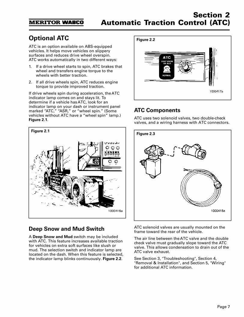
A Deep Snow and Mud switch may be included with ATC. This feature increases available traction for vehicles on extra soft surfaces like slush or mud. The selection switch and indicator lamp are located on the dash. When this feature is selected, the indicator lamp blinks continuously. Figure 2.2.
ATC Components
ATC uses two solenoid valves, two double-check valves, and a wiring harness with ATC connectors.
ATC solenoid valves are usually mounted on the frame toward the rear of the vehicle.
The air line between the ATC valve and the double check valve must gradually slope toward the ATC valve. This allows condensation to drain out of the ATC valve exhaust.
See Section 3, "Troubleshooting", Section 4, "Removal & Installation", and Section 5, "Wiring" for additional ATC information.
Figure 2.1
Figure 2.2
Figure 2.3

Notes
Page 8
Page 9
Section 3Troubleshooting
Section 3Troubleshooting
General Maintenance Information
There is no regularly scheduled maintenance required for the Meritor WABCO ABS or ABS/ATC. However, ABS does not change current vehicle maintenance requirements.
Troubleshooting
Suggested Diagnostic Tools
Standard: Blink Code Reference Information (see below).
Optional: Meritor WABCO Test Adaptor.
Optional: Pro-Link® 9000.
Blink Code Reference Information
To troubleshoot a possible ABS fault, use the blink code diagnostics built into the system. Before you begin, you should be familiar with the following definitions.
Blink Code Definitions
Blink Code: A series of blinks or flashes that describe a particular ABS system configuration and fault.
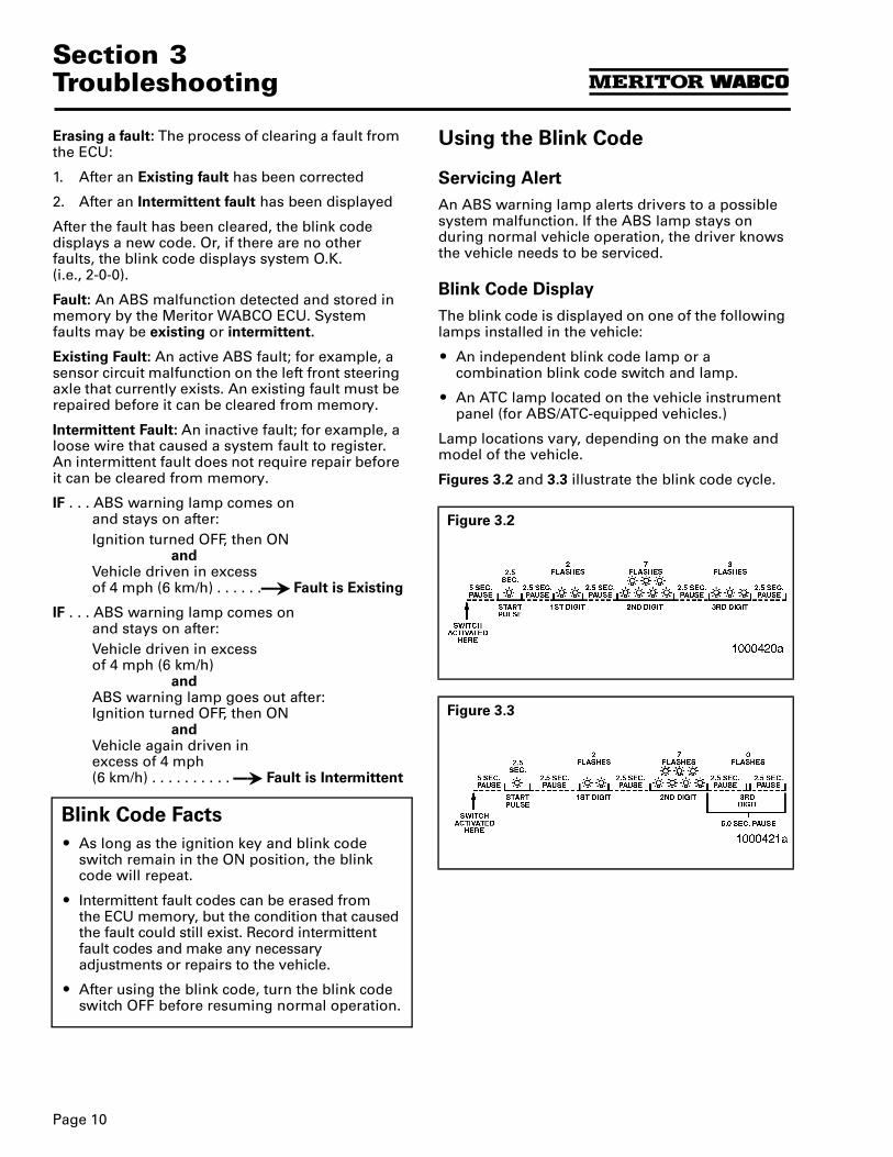
Blink Code Cycle: A set of three series of flashes, each set separated by a 2.5 second pause. The first set of flashes represents the system set-up:
1 flash = 6S/6M
2 flashes = 4S/4M
4 flashes = 6S/4M
The last two sets identify the system fault.
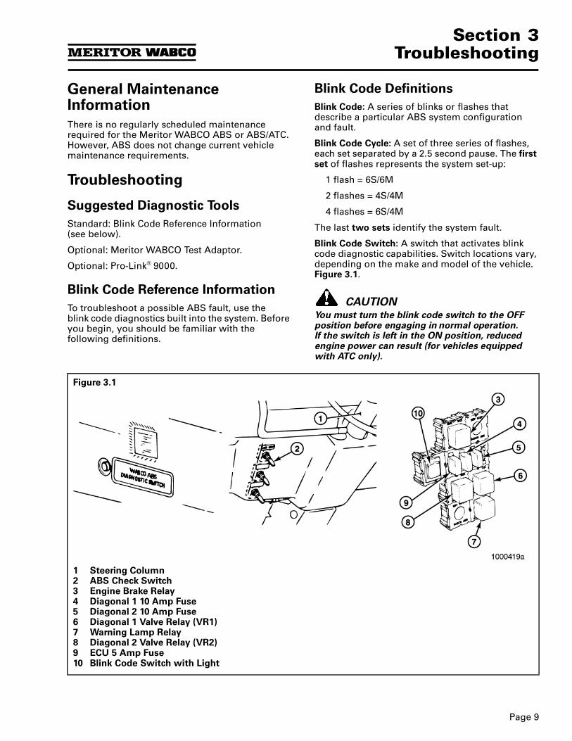
Blink Code Switch: A switch that activates blink code diagnostic capabilities. Switch locations vary, depending on the make and model of the vehicle. Figure 3.1.
CAUTIONYou must turn the blink code switch to the OFF position before engaging in normal operation.If the switch is left in the ON position, reduced engine power can result (for vehicles equipped with ATC only).
Figure 3.1
1 Steering Column2 ABS Check Switch3 Engine Brake Relay4 Diagonal 1 10 Amp Fuse5 Diagonal 2 10 Amp Fuse6 Diagonal 1 Valve Relay (VR1)7 Warning Lamp Relay8 Diagonal 2 Valve Relay (VR2)9 ECU 5 Amp Fuse10 Blink Code Switch with Light
Section 3Troubleshooting
Page 10
Erasing a fault: The process of clearing a fault from the ECU:
1. After an Existing fault has been corrected
2. After an Intermittent fault has been displayed
After the fault has been cleared, the blink code displays a new code. Or, if there are no other faults, the blink code displays system O.K. (i.e., 2-0-0).
Fault: An ABS malfunction detected and stored in memory by the Meritor WABCO ECU. System faults may be existing or intermittent.
Existing Fault: An active ABS fault; for example, a sensor circuit malfunction on the left front steering axle that currently exists. An existing fault must be repaired before it can be cleared from memory.
Intermittent Fault: An inactive fault; for example, a loose wire that caused a system fault to register. An intermittent fault does not require repair before it can be cleared from memory.
IF . . . ABS warning lamp comes on and stays on after:Ignition turned OFF, then ON
andVehicle driven in excess of 4 mph (6 km/h) . . . . . .35 Fault is Existing
IF . . . ABS warning lamp comes on and stays on after:Vehicle driven in excess of 4 mph (6 km/h)
andABS warning lamp goes out after: Ignition turned OFF, then ON
and Vehicle again driven in excess of 4 mph (6 km/h) . . . . . . . . . . 35 Fault is Intermittent
Blink Code Facts
O As long as the ignition key and blink codeswitch remain in the ON position, the blink code will repeat.
O Intermittent fault codes can be erased from the ECU memory, but the condition that caused the fault could still exist. Record intermittent fault codes and make any necessary adjustments or repairs to the vehicle.
O After using the blink code, turn the blink code switch OFF before resuming normal operation.
Using the Blink Code
Servicing Alert
An ABS warning lamp alerts drivers to a possible system malfunction. If the ABS lamp stays on during normal vehicle operation, the driver knows the vehicle needs to be serviced.
Blink Code Display
The blink code is displayed on one of the following lamps installed in the vehicle:
O An independent blink code lamp or a combination blink code switch and lamp.
O An ATC lamp located on the vehicle instrument panel (for ABS/ATC-equipped vehicles.)
Lamp locations vary, depending on the make and model of the vehicle.
Figures 3.2 and 3.3 illustrate the blink code cycle.
Figure 3.2
Figure 3.3
Page 11
Section 3Troubleshooting
Blink Code Diagnostic Procedure Follow these steps to use the blink code:
Working with Blink Code Diagnostics When using blink code diagnostics, the following conditions may occur:
Step — Action System Response Action
ITurn Ignition Key ON.
andTurn Blink Code Switch ON.
ABS lamp comes on and stays on.
Blink Code lamp comes on after approximately 5 seconds, then goes off.
At the end of 5 seconds, blink code cycle begins.
Observe lamps.
IIIdentify the 3-digit blink code.
First set of flashes (indicates system configuration).
Pause. . . . . . . . . . . . . . . . . . . . 35
Second set of flashes.
Pause.
Third set of flashes. . . . . . . . . . 35
Observe and record blink code.
After blink code is identified, turn blink code switch OFF, cycle will continue until all three sets of flashes have been displayed.
After COMPLETE blink code cycle, turn ignition OFF.
Look up 3-digit code on Diagnostics Chart or Blink Code Card, TP-94157.
IIIRepeat Step I to determine status of fault: Intermittent or Existing.
If a new code or a system O.K. code (i.e., 2-0-0) appears, fault was Intermittent.
NOTE: System O.K. code indicates fault erased from ECU memory.
If code repeats, fault is existing (active) and must be repaired.
Keep a record of fault for future reference.
NOTE: Make necessary adjustments or repairs to vehicle to prevent future occurrences.
Perform repair listed on Diagnostics Chart or TP-94157.Repeat procedure until System O.K. code received.
Step Condition Cause Action
I Lamp does not light.
Loose or burned out bulb. Check bulb.Check connections.Make necessary repairs.
Voltage not within acceptable range (11-15 volts).
Check connections.Measure voltage.Make necessary repairs.
I, III Code continues to repeat.
Ignition and blink code switch not turned off.
Turn Blink Code switch off.Wait for lamp to stop flashing.Turn Ignition off.
Fault not repaired. Review Diagnostics Chart or TP-94157 to ensure all possible conditions were corrected.Verify all repair work.
Fault not erased from ECU after report.
Repeat procedure until System O.K. code received.
II Code not listed on Diagnostics Chart or TP-94157.
Verify code (repeat Steps I and II).Contact Meritor WABCO Customer Service (800-535-5560) for assistance.
Section 3Troubleshooting
Page 12
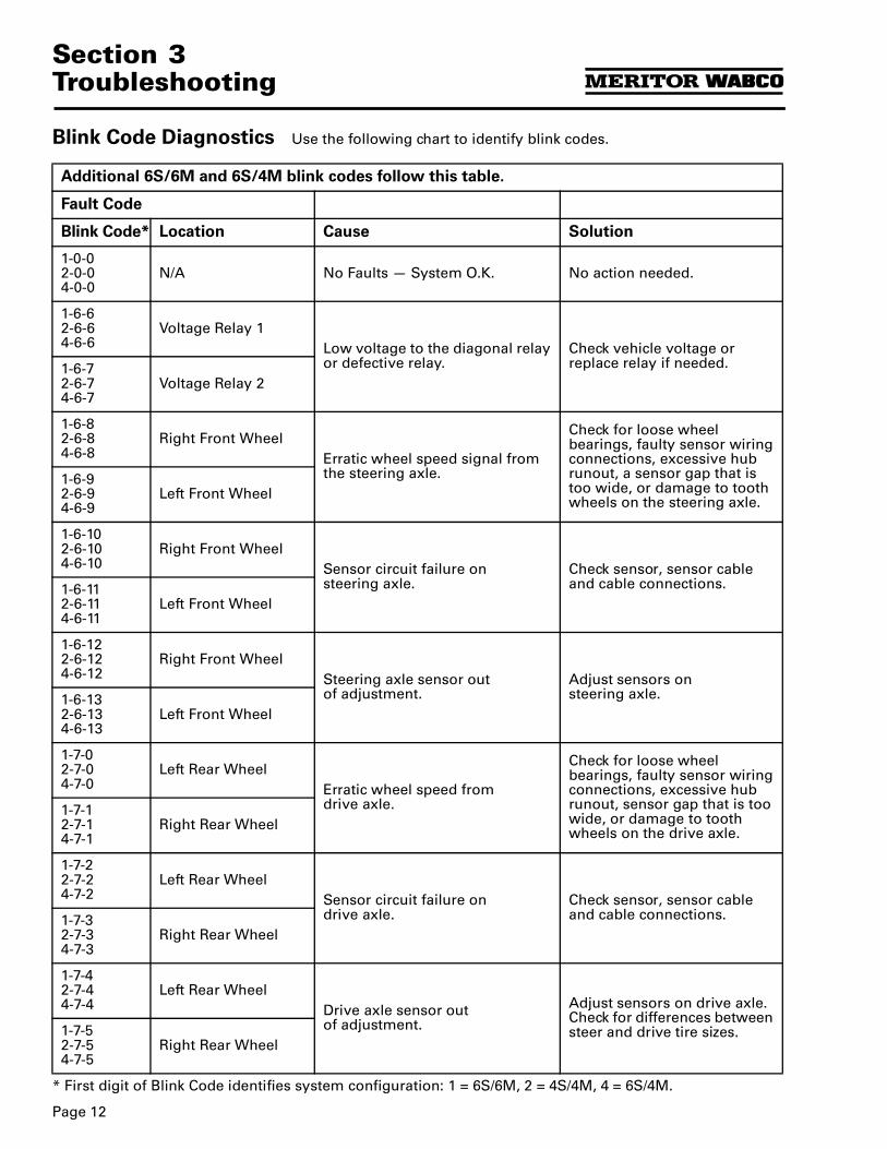
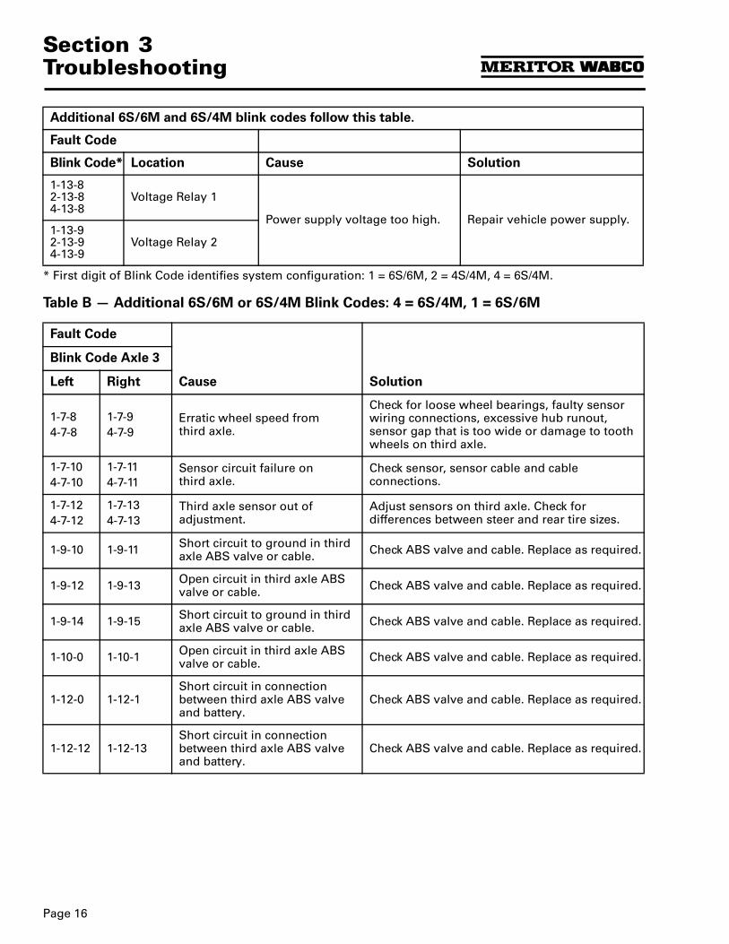
Blink Code Diagnostics Use the following chart to identify blink codes.
Additional 6S/6M and 6S/4M blink codes follow this table.
Fault Code
Blink Code* Location Cause Solution
1-0-02-0-04-0-0
N/A No Faults — System O.K. No action needed.
1-6-62-6-64-6-6
Voltage Relay 1Low voltage to the diagonal relay or defective relay.
Check vehicle voltage or replace relay if needed.1-6-7
2-6-74-6-7
Voltage Relay 2
1-6-82-6-84-6-8
Right Front WheelErratic wheel speed signal from the steering axle.
Check for loose wheel bearings, faulty sensor wiring connections, excessive hub runout, a sensor gap that is too wide, or damage to tooth wheels on the steering axle.
1-6-92-6-94-6-9
Left Front Wheel
1-6-102-6-104-6-10
Right Front WheelSensor circuit failure on steering axle.
Check sensor, sensor cable and cable connections.1-6-11
2-6-114-6-11
Left Front Wheel
1-6-122-6-124-6-12
Right Front WheelSteering axle sensor out of adjustment.
Adjust sensors on steering axle.1-6-13
2-6-134-6-13
Left Front Wheel
1-7-02-7-04-7-0
Left Rear WheelErratic wheel speed from drive axle.
Check for loose wheel bearings, faulty sensor wiring connections, excessive hub runout, sensor gap that is too wide, or damage to tooth wheels on the drive axle.
1-7-12-7-14-7-1
Right Rear Wheel
1-7-22-7-24-7-2
Left Rear WheelSensor circuit failure on drive axle.
Check sensor, sensor cable and cable connections.1-7-3
2-7-34-7-3
Right Rear Wheel
1-7-42-7-44-7-4
Left Rear WheelDrive axle sensor out of adjustment.
Adjust sensors on drive axle. Check for differences between steer and drive tire sizes.1-7-5
2-7-54-7-5
Right Rear Wheel
* First digit of Blink Code identifies system configuration: 1 = 6S/6M, 2 = 4S/4M, 4 = 6S/4M.
Page 13
Section 3Troubleshooting
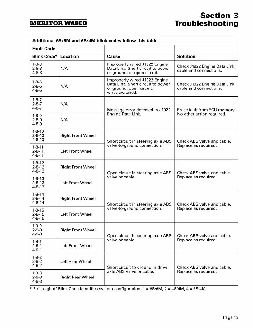
1-8-32-8-34-8-3
N/AImproperly wired J1922 Engine Data Link. Short circuit to power or ground, or open circuit.
Check J1922 Engine Data Link, cable and connections.
1-8-52-8-54-8-5
N/A
Improperly wired J1922 Engine Data Link. Short circuit to power or ground, open circuit,wires switched.
Check J1922 Engine Data Link, cable and connections.
1-8-72-8-74-8-7
N/AMessage error detected in J1922 Engine Data Link.
Erase fault from ECU memory. No other action required.1-8-9
2-8-94-8-9
N/A
1-8-102-8-104-8-10
Right Front WheelShort circuit in steering axle ABS valve-to-ground connection.
Check ABS valve and cable. Replace as required.1-8-11
2-8-114-8-11
Left Front Wheel
1-8-122-8-124-8-12
Right Front WheelOpen circuit in steering axle ABS valve or cable.
Check ABS valve and cable. Replace as required.1-8-13
2-8-134-8-13
Left Front Wheel
1-8-142-8-144-8-14
Right Front WheelShort circuit in steering axle ABS valve-to-ground connection.
Check ABS valve and cable. Replace as required.1-8-15
2-8-154-8-15
Left Front Wheel
1-9-02-9-04-9-0
Right Front WheelOpen circuit in steering axle ABS valve or cable.
Check ABS valve and cable. Replace as required.1-9-1
2-9-14-9-1
Left Front Wheel
1-9-22-9-24-9-2
Left Rear WheelShort circuit to ground in drive axle ABS valve or cable.
Check ABS valve and cable. Replace as required.1-9-3
2-9-34-9-3
Right Rear Wheel
Additional 6S/6M and 6S/4M blink codes follow this table.
Fault Code
Blink Code* Location Cause Solution
* First digit of Blink Code identifies system configuration: 1 = 6S/6M, 2 = 4S/4M, 4 = 6S/4M.
Section 3Troubleshooting
Page 14
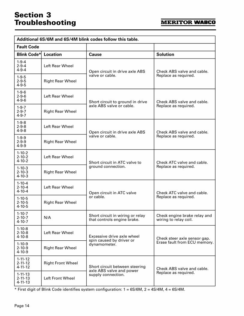
1-9-42-9-44-9-4
Left Rear WheelOpen circuit in drive axle ABS valve or cable.
Check ABS valve and cable. Replace as required.1-9-5
2-9-54-9-5
Right Rear Wheel
1-9-62-9-64-9-6
Left Rear WheelShort circuit to ground in drive axle ABS valve or cable.
Check ABS valve and cable. Replace as required.1-9-7
2-9-74-9-7
Right Rear Wheel
1-9-82-9-84-9-8
Left Rear WheelOpen circuit in drive axle ABS valve or cable.
Check ABS valve and cable. Replace as required.1-9-9
2-9-94-9-9
Right Rear Wheel
1-10-22-10-24-10-2
Left Rear WheelShort circuit in ATC valve to ground connection.
Check ATC valve and cable. Replace as required.1-10-3
2-10-34-10-3
Right Rear Wheel
1-10-42-10-44-10-4
Left Rear WheelOpen circuit in ATC valve or cable.
Check ATC valve and cable. Replace as required.1-10-5
2-10-54-10-5
Right Rear Wheel
1-10-72-10-74-10-7
N/A Short circuit in wiring or relay that controls engine brake.
Check engine brake relay and wiring to relay coil.
1-10-82-10-84-10-8
Left Rear WheelExcessive drive axle wheelspin caused by driver or dynamometer.
Check steer axle sensor gap. Erase fault from ECU memory.1-10-9
2-10-94-10-9
Right Rear Wheel
1-11-122-11-124-11-12
Right Front WheelShort circuit between steering axle ABS valve and power supply connection.
Check ABS valve and cable. Replace as required.1-11-13
2-11-134-11-13
Left Front Wheel
Additional 6S/6M and 6S/4M blink codes follow this table.
Fault Code
Blink Code* Location Cause Solution
* First digit of Blink Code identifies system configuration: 1 = 6S/6M, 2 = 4S/4M, 4 = 6S/4M.
Page 15
Section 3Troubleshooting
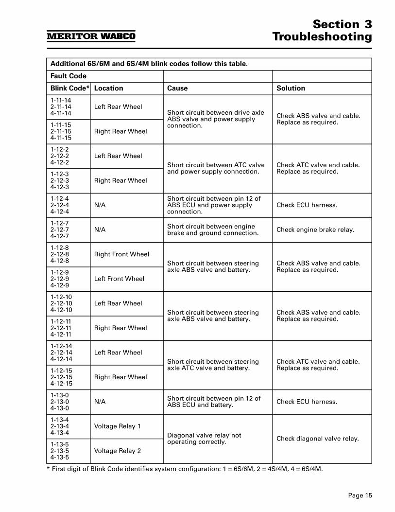
1-11-142-11-144-11-14
Left Rear WheelShort circuit between drive axle ABS valve and power supply connection.
Check ABS valve and cable. Replace as required.1-11-15
2-11-154-11-15
Right Rear Wheel
1-12-22-12-24-12-2
Left Rear WheelShort circuit between ATC valve and power supply connection.
Check ATC valve and cable. Replace as required.1-12-3
2-12-34-12-3
Right Rear Wheel
1-12-42-12-44-12-4
N/AShort circuit between pin 12 of ABS ECU and power supply connection.
Check ECU harness.
1-12-72-12-74-12-7
N/A Short circuit between engine brake and ground connection. Check engine brake relay.
1-12-82-12-84-12-8
Right Front WheelShort circuit between steering axle ABS valve and battery.
Check ABS valve and cable. Replace as required.1-12-9
2-12-94-12-9
Left Front Wheel
1-12-102-12-104-12-10
Left Rear WheelShort circuit between steering axle ABS valve and battery.
Check ABS valve and cable. Replace as required.1-12-11
2-12-114-12-11
Right Rear Wheel
1-12-142-12-144-12-14
Left Rear WheelShort circuit between steering axle ATC valve and battery.
Check ATC valve and cable. Replace as required.1-12-15
2-12-154-12-15
Right Rear Wheel
1-13-02-13-04-13-0
N/A Short circuit between pin 12 of ABS ECU and battery. Check ECU harness.
1-13-42-13-44-13-4
Voltage Relay 1Diagonal valve relay not operating correctly. Check diagonal valve relay.
1-13-52-13-54-13-5
Voltage Relay 2
Additional 6S/6M and 6S/4M blink codes follow this table.
Fault Code
Blink Code* Location Cause Solution
* First digit of Blink Code identifies system configuration: 1 = 6S/6M, 2 = 4S/4M, 4 = 6S/4M.
Section 3Troubleshooting
Page 16
Table B — Additional 6S/6M or 6S/4M Blink Codes: 4 = 6S/4M, 1 = 6S/6M
1-13-82-13-84-13-8
Voltage Relay 1
Power supply voltage too high. Repair vehicle power supply.1-13-92-13-94-13-9
Voltage Relay 2
Fault Code
Cause Solution
Blink Code Axle 3
Left Right
1-7-84-7-8
1-7-94-7-9
Erratic wheel speed fromthird axle.
Check for loose wheel bearings, faulty sensor wiring connections, excessive hub runout, sensor gap that is too wide or damage to tooth wheels on third axle.
1-7-104-7-10
1-7-114-7-11
Sensor circuit failure onthird axle.
Check sensor, sensor cable and cable connections.
1-7-124-7-12
1-7-134-7-13
Third axle sensor out of adjustment.
Adjust sensors on third axle. Check for differences between steer and rear tire sizes.
1-9-10 1-9-11 Short circuit to ground in third axle ABS valve or cable. Check ABS valve and cable. Replace as required.
1-9-12 1-9-13 Open circuit in third axle ABS valve or cable. Check ABS valve and cable. Replace as required.
1-9-14 1-9-15 Short circuit to ground in third axle ABS valve or cable. Check ABS valve and cable. Replace as required.
1-10-0 1-10-1 Open circuit in third axle ABS valve or cable. Check ABS valve and cable. Replace as required.
1-12-0 1-12-1Short circuit in connection between third axle ABS valve and battery.
Check ABS valve and cable. Replace as required.
1-12-12 1-12-13Short circuit in connection between third axle ABS valve and battery.
Check ABS valve and cable. Replace as required.
Additional 6S/6M and 6S/4M blink codes follow this table.
Fault Code
Blink Code* Location Cause Solution
* First digit of Blink Code identifies system configuration: 1 = 6S/6M, 2 = 4S/4M, 4 = 6S/4M.
Page 17
Section 3Troubleshooting
TestingThe locations of sensors and valves are illustrated in Figures 3.4–3.9. Most vehicles with spring suspension have sensors on forward-rear axle. Most vehicles with air suspension have sensors on rear-rear axle.
Liftable axles are always the third axle with ABS.
Figure 3.4
Figure 3.5
Figure 3.6
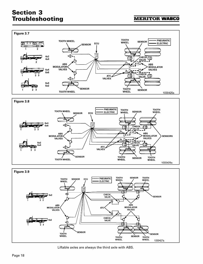
Section 3Troubleshooting
Page 18
Liftable axles are always the third axle with ABS.
Figure 3.7
Figure 3.8
Figure 3.9
Page 19
Section 3Troubleshooting
Optional Test Equipment
WARNINGS
Exhaust gas contains poison. When testing a vehicle with the engine running, test in a well-ventilated area or route the exhaust hose outside
To avoid serious personal injury, keep away, and keep test equipment away, from all moving or hot engine parts.
NOTES
OOOO Refer to, and follow, the vehicle manufacturer's Warnings, Cautions, and Service Procedures.
OOOO Unless otherwise directed, set the parking brake and place the gear selector in NEUTRAL (manual transmission) or PARK (automatic transmission).
Meritor WABCO Test Adaptor
O For use with cab-mounted ECUs only.
CAUTIONWhen troubleshooting or testing the system at the main connector, be careful not to damage the electrical sockets.
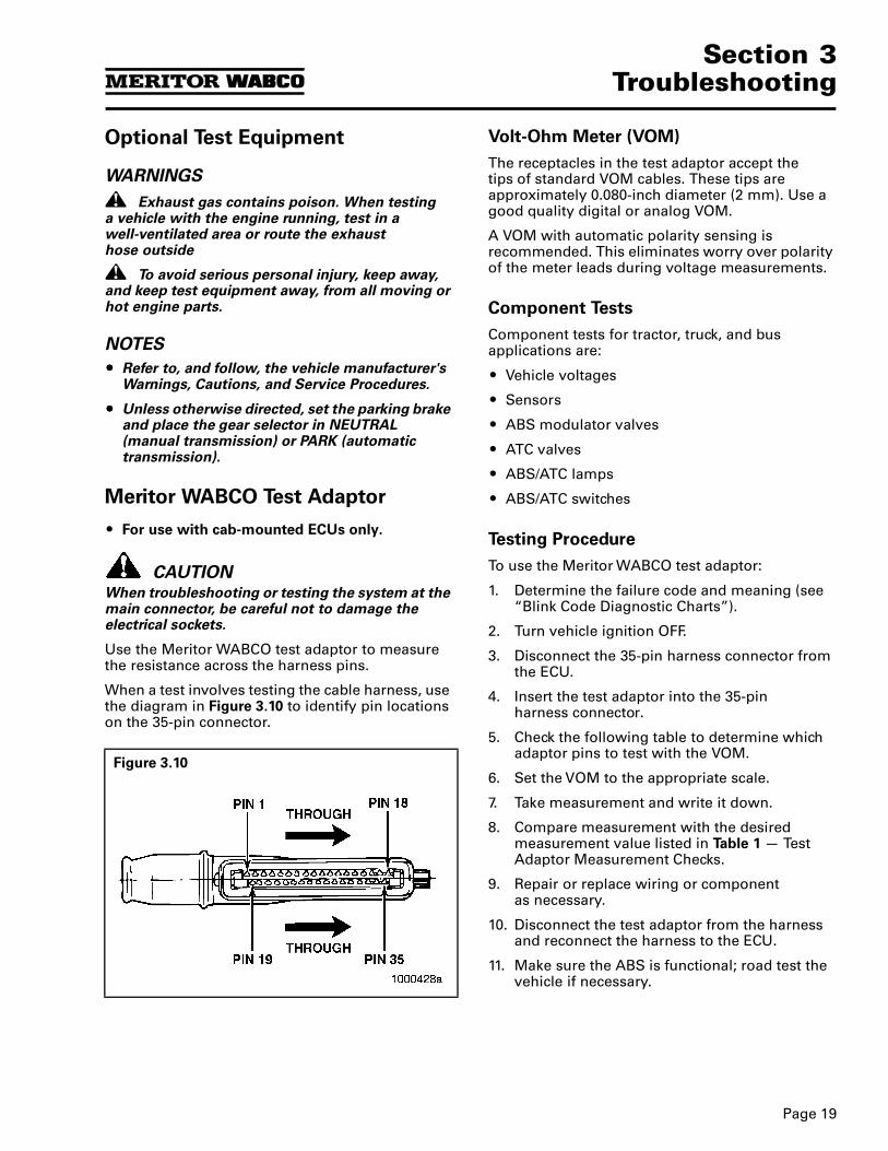
Use the Meritor WABCO test adaptor to measure the resistance across the harness pins.
When a test involves testing the cable harness, use the diagram in Figure 3.10 to identify pin locations on the 35-pin connector.
Volt-Ohm Meter (VOM)
The receptacles in the test adaptor accept the tips of standard VOM cables. These tips are approximately 0.080-inch diameter (2 mm). Use a good quality digital or analog VOM.
A VOM with automatic polarity sensing is recommended. This eliminates worry over polarity of the meter leads during voltage measurements.
Component Tests
Component tests for tractor, truck, and bus applications are:
O Vehicle voltages
O Sensors
O ABS modulator valves
O ATC valves
O ABS/ATC lamps
O ABS/ATC switches
Testing Procedure
To use the Meritor WABCO test adaptor:
1. Determine the failure code and meaning (see “Blink Code Diagnostic Charts”).
2. Turn vehicle ignition OFF.
3. Disconnect the 35-pin harness connector from the ECU.
4. Insert the test adaptor into the 35-pinharness connector.
5. Check the following table to determine which adaptor pins to test with the VOM.
6. Set the VOM to the appropriate scale.
7. Take measurement and write it down.
8. Compare measurement with the desired measurement value listed in Table 1 — Test Adaptor Measurement Checks.
9. Repair or replace wiring or component as necessary.
10. Disconnect the test adaptor from the harness and reconnect the harness to the ECU.
11. Make sure the ABS is functional; road test the vehicle if necessary.
Figure 3.10
Section 3Troubleshooting
Page 20
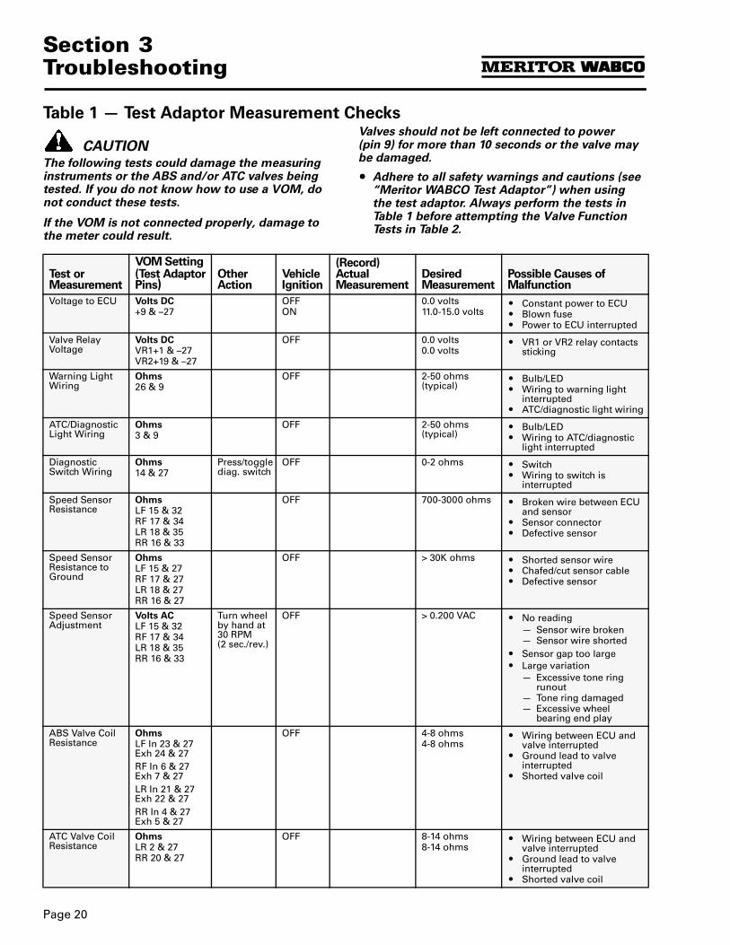
Table 1 — Test Adaptor Measurement Checks
CAUTIONThe following tests could damage the measuring instruments or the ABS and/or ATC valves being tested. If you do not know how to use a VOM, do not conduct these tests.
If the VOM is not connected properly, damage to the meter could result.
Valves should not be left connected to power (pin 9) for more than 10 seconds or the valve may be damaged.
OOOO Adhere to all safety warnings and cautions (see “Meritor WABCO Test Adaptor”) when using the test adaptor. Always perform the tests in Table 1 before attempting the Valve Function Tests in Table 2.
Test or Measurement
VOM Setting(Test Adaptor Pins)
Other Action
Vehicle Ignition
(Record) Actual Measurement
Desired Measurement
Possible Causes of Malfunction
Voltage to ECU Volts DC+9 & –27
OFFON
0.0 volts11.0-15.0 volts
O Constant power to ECUO Blown fuseO Power to ECU interrupted
Valve Relay Voltage
Volts DCVR1+1 & –27VR2+19 & –27
OFF 0.0 volts0.0 volts
O VR1 or VR2 relay contacts sticking
Warning Light Wiring
Ohms26 & 9
OFF 2-50 ohms (typical)
O Bulb/LEDO Wiring to warning light
interruptedO ATC/diagnostic light wiring
ATC/Diagnostic Light Wiring
Ohms3 & 9
OFF 2-50 ohms (typical)
O Bulb/LEDO Wiring to ATC/diagnostic
light interrupted
Diagnostic Switch Wiring
Ohms14 & 27
Press/toggle diag. switch
OFF 0-2 ohms O SwitchO Wiring to switch is
interrupted
Speed Sensor Resistance
OhmsLF 15 & 32RF 17 & 34LR 18 & 35RR 16 & 33
OFF 700-3000 ohms O Broken wire between ECU and sensor
O Sensor connectorO Defective sensor
Speed Sensor Resistance to Ground
OhmsLF 15 & 27RF 17 & 27LR 18 & 27RR 16 & 27
OFF > 30K ohms O Shorted sensor wireO Chafed/cut sensor cableO Defective sensor
Speed Sensor Adjustment
Volts ACLF 15 & 32RF 17 & 34LR 18 & 35RR 16 & 33
Turn wheel by hand at 30 RPM (2 sec./rev.)
OFF > 0.200 VAC O No reading— Sensor wire broken— Sensor wire shorted
O Sensor gap too largeO Large variation
— Excessive tone ring runout
— Tone ring damaged— Excessive wheel
bearing end play
ABS Valve Coil Resistance
OhmsLF In 23 & 27 Exh 24 & 27RF In 6 & 27 Exh 7 & 27LR In 21 & 27 Exh 22 & 27RR In 4 & 27 Exh 5 & 27
OFF 4-8 ohms4-8 ohms
O Wiring between ECU and valve interrupted
O Ground lead to valve interrupted
O Shorted valve coil
ATC Valve Coil Resistance
OhmsLR 2 & 27RR 20 & 27
OFF 8-14 ohms8-14 ohms
O Wiring between ECU and valve interrupted
O Ground lead to valve interrupted
O Shorted valve coil
Page 21
Section 3Troubleshooting
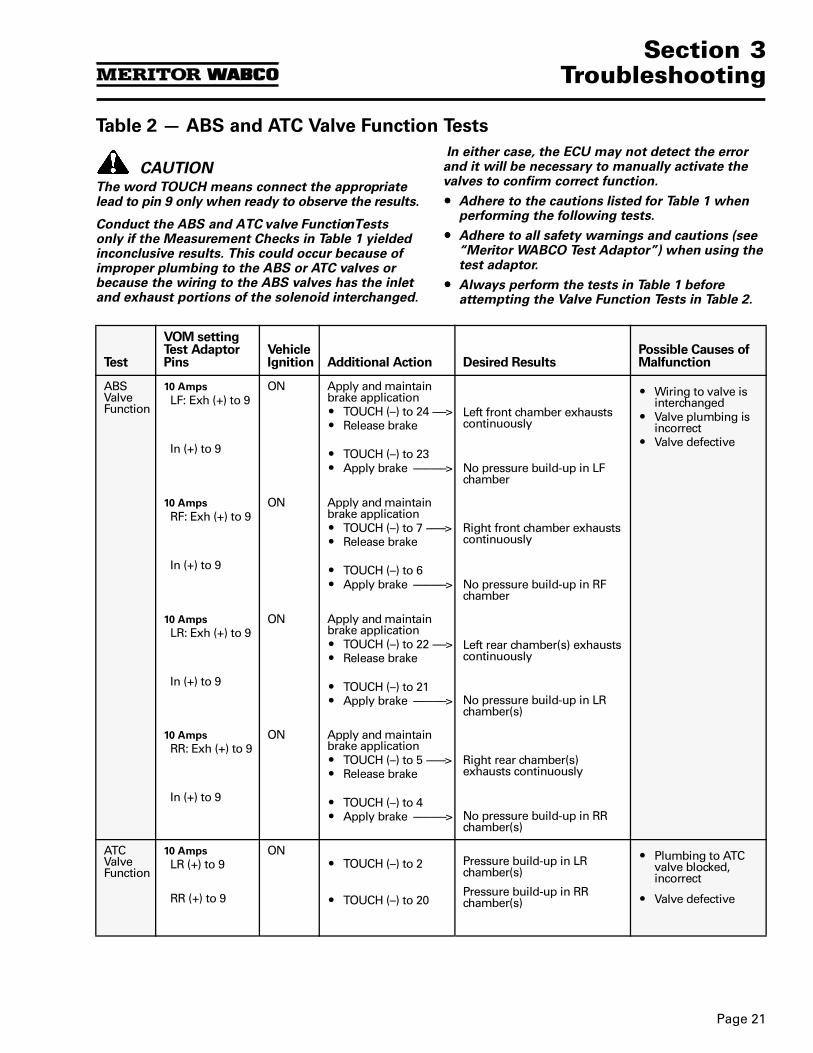
Table 2 — ABS and ATC Valve Function Tests
CAUTIONThe word TOUCH means connect the appropriate lead to pin 9 only when ready to observe the results.
Conduct the ABS and ATC valve Function Tests only if the Measurement Checks in Table 1 yielded inconclusive results. This could occur because of improper plumbing to the ABS or ATC valves or because the wiring to the ABS valves has the inlet and exhaust portions of the solenoid interchanged.
In either case, the ECU may not detect the error and it will be necessary to manually activate the valves to confirm correct function.
OOOO Adhere to the cautions listed for Table 1 when performing the following tests.
OOOO Adhere to all safety warnings and cautions (see “Meritor WABCO Test Adaptor”) when using the test adaptor.
OOOO Always perform the tests in Table 1 before attempting the Valve Function Tests in Table 2.
Test
VOM setting Test Adaptor Pins
Vehicle Ignition Additional Action Desired Results
Possible Causes of Malfunction
ABS Valve Function
10 Amps
LF: Exh (+) to 9ON Apply and maintain
brake applicationO TOUCH (–) to 24 ----->O Release brake
Left front chamber exhausts continuously
O Wiring to valve is interchanged
O Valve plumbing is incorrect
O Valve defective In (+) to 9 O TOUCH (–) to 23O Apply brake ------------> No pressure build-up in LF
chamber
10 Amps
RF: Exh (+) to 9ON Apply and maintain
brake applicationO TOUCH (–) to 7 ------->O Release brake
Right front chamber exhausts continuously
In (+) to 9 O TOUCH (–) to 6O Apply brake ------------> No pressure build-up in RF
chamber
10 Amps
LR: Exh (+) to 9ON Apply and maintain
brake applicationO TOUCH (–) to 22 ----->O Release brake
Left rear chamber(s) exhausts continuously
In (+) to 9 O TOUCH (–) to 21O Apply brake ------------> No pressure build-up in LR
chamber(s)
10 Amps
RR: Exh (+) to 9ON Apply and maintain
brake applicationO TOUCH (–) to 5 ------->O Release brake
Right rear chamber(s) exhausts continuously
In (+) to 9 O TOUCH (–) to 4O Apply brake ------------> No pressure build-up in RR
chamber(s)
ATC Valve Function
10 Amps
LR (+) to 9
RR (+) to 9
ONO TOUCH (–) to 2
O TOUCH (–) to 20
Pressure build-up in LR chamber(s)
Pressure build-up in RR chamber(s)
O Plumbing to ATC valve blocked, incorrect
O Valve defective
Section 3Troubleshooting
Page 22
Final Test for a Tractor Equipped with ABS
NOTETurn the blink code switch to the OFF position. Complete the following test.
For a Tractor Equipped with ABS:
1. Check that the cab harness is attached tothe ECU.
2. Start the engine.
3. Increase vehicle speed. At about 4 mph (6 km/h), the tractor warning light must to out.
NOTES
OOOO If the tractor warning light continues to stay on, check blink codes, all components and connections.
OOOO When failures cannot be repaired, contact your Meritor District Service Manager at 800-535-5560 in the U.S. and Canada.
MPSI Pro-Link® 9000
Use the Pro-Link® 9000 to:
O Diagnose System Faults on ABS and ABS/ATC systems with C2 and C3 ECUs. (May be used in place of blink code diagnostic procedures.)
O Perform component measurement andfunction tests.
NOTEPro-Link® screens identify faults as existing or stored. See “Blink Code Definitions” for definitions.
Component Tests
Components that may be tested with the Pro-Link® 9000 are:
NOTEAdhere to all safety Warnings and Cautions (see “Meritor WABCO Test Adaptor”).
Diagnostic and Testing Procedure
1. Locate the 6-pin connector in the vehicle cab. Gather together everything you need during the test.
O Pro-Link® 9000
O Meritor WABCO test cartridge
O 6-pin connector
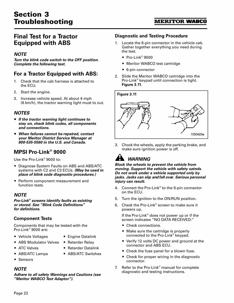
2. Slide the Meritor WABCO cartridge into the Pro-Link® keypad until connection is tight. Figure 3.11.
3. Chock the wheels, apply the parking brake, and make sure ignition power is off.
WARNINGBlock the wheels to prevent the vehicle from moving. Support the vehicle with safety satnds. Do not work under a vehicle supported only by jacks. Jacks can slip and fall over. Serious personal injury can result.
4. Connect the Pro-Link® to the 6-pin connector on the ECU.
5. Turn the ignition to the ON/RUN position.
6. Check the Pro-Link® screen to make sure it powers up.
If the Pro-Link® does not power up or if the screen indicates “NO DATA RECEIVED:”
O Check connections.
O Make sure the cartridge is properly connected to the Pro-Link® keypad.
O Verify 12 volts DC power and ground at the connector and ABS ECU.
O Check the fuse panel for a blown fuse.
O Check for proper wiring in the diagnostic connector.
7. Refer to the Pro-Link® manual for complete diagnostic and testing instructions.
O Vehicle Voltages
O ABS Modulator Valves
O ATC Valves
O ABS/ATC Lamps
O Sensors
O Engine Datalink
O Retarder Relay
O Retarder Datalink
O ABS/ATC Switches
Figure 3.11
Page 23
Section 3Troubleshooting
Testing and Diagnostic Screens
NOTEThe menu selections for the Pro-Link® are described below. Refer to the Pro-Link® manual for complete testing instructions.
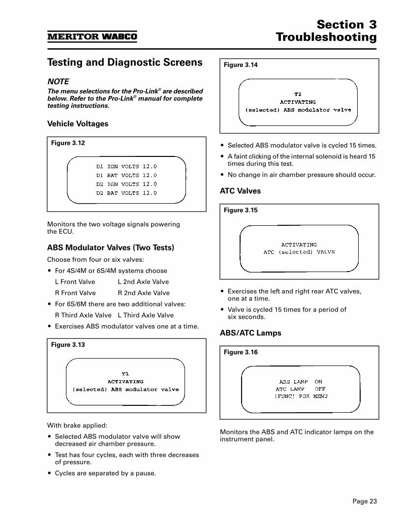
Vehicle Voltages
Monitors the two voltage signals poweringthe ECU.
ABS Modulator Valves (Two Tests)
Choose from four or six valves:
O For 4S/4M or 6S/4M systems choose
L Front Valve L 2nd Axle Valve
R Front Valve R 2nd Axle Valve
O For 6S/6M there are two additional valves:
R Third Axle Valve L Third Axle Valve
O Exercises ABS modulator valves one at a time.
With brake applied:
O Selected ABS modulator valve will show decreased air chamber pressure.
O Test has four cycles, each with three decreases of pressure.
O Cycles are separated by a pause.
O Selected ABS modulator valve is cycled 15 times.
O A faint clicking of the internal solenoid is heard 15 times during this test.
O No change in air chamber pressure should occur.
ATC Valves
O Exercises the left and right rear ATC valves, one at a time.
O Valve is cycled 15 times for a period of six seconds.
ABS/ATC Lamps
Monitors the ABS and ATC indicator lamps on the instrument panel.
Figure 3.12
Figure 3.13
Figure 3.14
Figure 3.15
Figure 3.16
Section 3Troubleshooting
Page 24
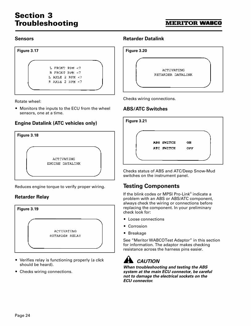
Sensors
Rotate wheel:
O Monitors the inputs to the ECU from the wheel sensors, one at a time.
Engine Datalink (ATC vehicles only)
Reduces engine torque to verify proper wiring.
Retarder Relay
O Verifies relay is functioning properly (a click should be heard).
O Checks wiring connections.
Retarder Datalink
Checks wiring connections.
ABS/ATC Switches
Checks status of ABS and ATC/Deep Snow-Mud switches on the instrument panel.
Testing Components
If the blink codes or MPSI Pro-Link® indicate a problem with an ABS or ABS/ATC component, always check the wiring or connections before replacing the component. In your preliminary check look for:
O Loose connections
O Corrosion
O Breakage
See “Meritor WABCO Test Adaptor” in this section for information. The adaptor makes checking resistance across the harness pins easier.
CAUTIONWhen troubleshooting and testing the ABS system at the main ECU connector, be careful not to damage the electrical sockets on the ECU connector.
Figure 3.17
Figure 3.18
Figure 3.19
Figure 3.20
Figure 3.21
Page 25
Section 3Troubleshooting
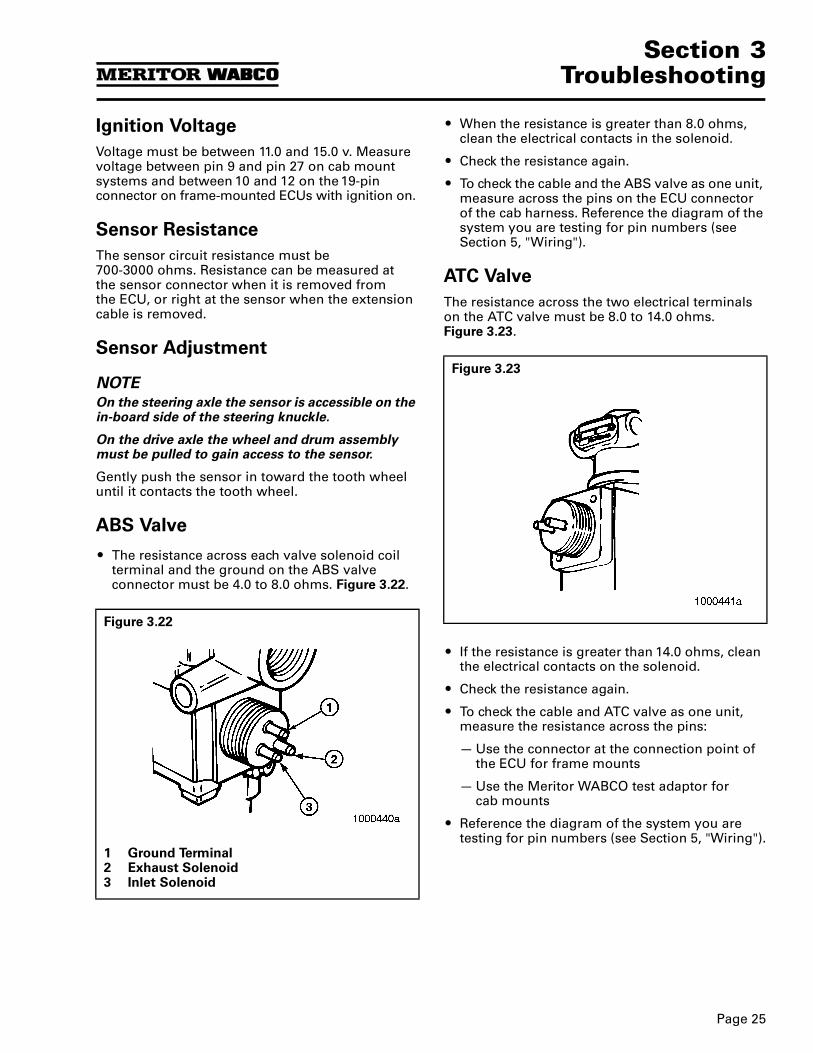
Ignition Voltage
Voltage must be between 11.0 and 15.0 v. Measure voltage between pin 9 and pin 27 on cab mount systems and between 10 and 12 on the 19-pin connector on frame-mounted ECUs with ignition on.
Sensor Resistance
The sensor circuit resistance must be 700-3000 ohms. Resistance can be measured at the sensor connector when it is removed fromthe ECU, or right at the sensor when the extension cable is removed.
Sensor Adjustment
NOTEOn the steering axle the sensor is accessible on the in-board side of the steering knuckle.
On the drive axle the wheel and drum assembly must be pulled to gain access to the sensor.
Gently push the sensor in toward the tooth wheel until it contacts the tooth wheel.
ABS Valve
O The resistance across each valve solenoid coil terminal and the ground on the ABS valve connector must be 4.0 to 8.0 ohms. Figure 3.22.
O When the resistance is greater than 8.0 ohms, clean the electrical contacts in the solenoid.
O Check the resistance again.
O To check the cable and the ABS valve as one unit, measure across the pins on the ECU connector of the cab harness. Reference the diagram of the system you are testing for pin numbers (see Section 5, "Wiring").
ATC Valve
The resistance across the two electrical terminals on the ATC valve must be 8.0 to 14.0 ohms. Figure 3.23.
O If the resistance is greater than 14.0 ohms, clean the electrical contacts on the solenoid.
O Check the resistance again.
O To check the cable and ATC valve as one unit, measure the resistance across the pins:
— Use the connector at the connection point of the ECU for frame mounts
— Use the Meritor WABCO test adaptor for cab mounts
O Reference the diagram of the system you are testing for pin numbers (see Section 5, "Wiring").
Figure 3.22
1 Ground Terminal2 Exhaust Solenoid3 Inlet Solenoid
Figure 3.23
Section 3Troubleshooting
Page 26
Dynamometer Testing Vehicles with ATC
WARNINGFailure to disable the ATC before dynamometer testing could result in serious personal injury and damage to the vehicle.
Vehicles with the ATC option must have the ABS system power disabled to test the vehicle on a dynamometer. The method requires removing the “ABS” circuit breaker/fuse or removing the ECU main connector. Disconnect connector or breaker with ignition in the OFF position.
Tire Size Range
CAUTIONFor proper ABS/ATC operation with the standard Electronic Control Unit (ECU), front and rear tire sizes must be within ± 5% of each other. When this tire size range is exceeded without electronically modifying the ECU, the system performance can be affected and the warning lamp can illuminate. Call Meritor WABCO at800/535-5560 when you plan a tire size difference greater than 5%.
Calculate tire size with the following equation:
% Difference = (RPM Steer ÷ RPM Drive — 1) x 100
RPM = tire revolutions per mile
Page 27
Section 4Removal & Installation
Section 4Removal & Installation
Component Removal and Installation
WARNINGTo prevent serious eye injury, always wear safe eye protection when you perform vehicle maintenance or service.
CAUTIONUse the following procedures to avoid damage to the electrical system and ABS/ATC components.
When welding on an ABS- or ABS/ATC-equipped vehicle is necessary, disconnect power and ground leads from the ECU.
Sensors
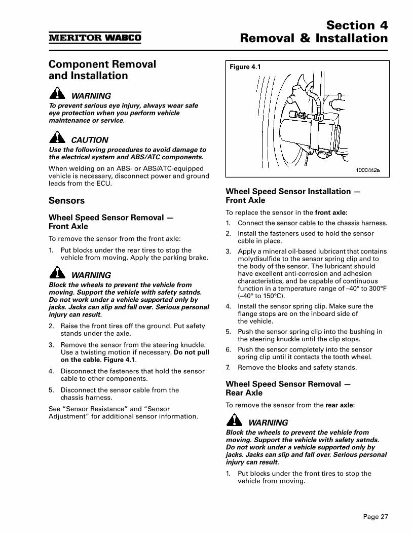
Wheel Speed Sensor Removal — Front Axle
To remove the sensor from the front axle:
1. Put blocks under the rear tires to stop the vehicle from moving. Apply the parking brake.
WARNINGBlock the wheels to prevent the vehicle from moving. Support the vehicle with safety satnds. Do not work under a vehicle supported only by jacks. Jacks can slip and fall over. Serious personal injury can result.
2. Raise the front tires off the ground. Put safety stands under the axle.
3. Remove the sensor from the steering knuckle. Use a twisting motion if necessary. Do not pull on the cable. Figure 4.1.
4. Disconnect the fasteners that hold the sensor cable to other components.
5. Disconnect the sensor cable from the chassis harness.
See “Sensor Resistance” and “Sensor Adjustment” for additional sensor information.
Wheel Speed Sensor Installation — Front Axle
To replace the sensor in the front axle:
1. Connect the sensor cable to the chassis harness.
2. Install the fasteners used to hold the sensor cable in place.
3. Apply a mineral oil-based lubricant that contains molydisulfide to the sensor spring clip and to the body of the sensor. The lubricant should have excellent anti-corrosion and adhesion characteristics, and be capable of continuous function in a temperature range of –40° to 300°F (–40° to 150°C).
4. Install the sensor spring clip. Make sure the flange stops are on the inboard side ofthe vehicle.
5. Push the sensor spring clip into the bushing in the steering knuckle until the clip stops.
6. Push the sensor completely into the sensor spring clip until it contacts the tooth wheel.
7. Remove the blocks and safety stands.
Wheel Speed Sensor Removal — Rear Axle
To remove the sensor from the rear axle:
WARNINGBlock the wheels to prevent the vehicle from moving. Support the vehicle with safety satnds. Do not work under a vehicle supported only by jacks. Jacks can slip and fall over. Serious personal injury can result.
1. Put blocks under the front tires to stop the vehicle from moving.
Figure 4.1
Section 4Removal & Installation
Page 28
2. Raise the rear tire off the ground. Put safety stands under the axle.
3. Release the parking brake and back off the slack adjuster to release the brake shoes.
4. Remove the wheel and tire assembly fromthe axle.
5. Remove the brake drum.
6. Remove the sensor from the mounting block in the axle housing. Use a twisting motion if necessary. Do not pull on the cable.
7. Remove the sensor spring clip from the mounting block.
8. Disconnect the fasteners that hold the sensor cable and the hose clamp to other components.
9. Disconnect the sensor cable from the chassis harness.
Wheel Speed Sensor Installation — Rear Axle
1. Apply a mineral oil-based lubricant that contains molydisulfide to the sensor spring clip and to the body of the sensor. The lubricant should have excellent anti-corrosion and adhesion characteristics, and be capable of continuous function in a temperature range of –40° to 300°F (–40° to 150°C).
2. Install the sensor spring clip. Make sure the flange stops are on the inboard side ofthe vehicle.
3. Push the sensor spring clip into the mounting block until it stops.
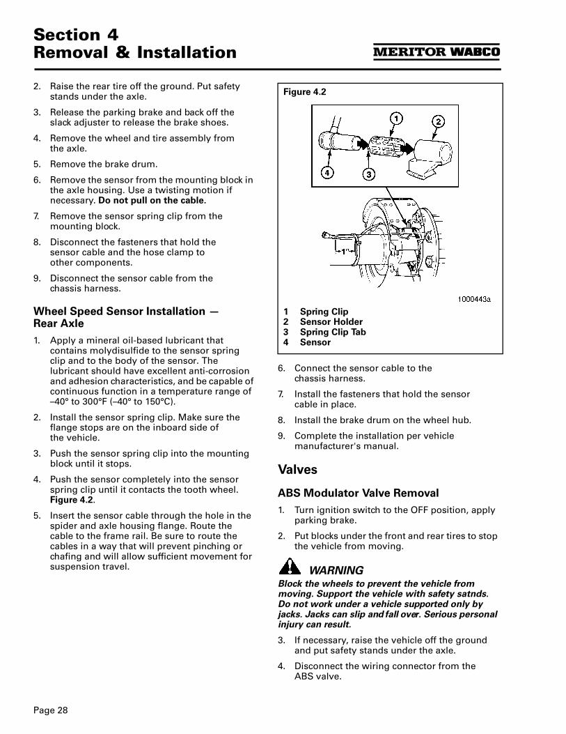
4. Push the sensor completely into the sensor spring clip until it contacts the tooth wheel. Figure 4.2.
5. Insert the sensor cable through the hole in the spider and axle housing flange. Route the cable to the frame rail. Be sure to route the cables in a way that will prevent pinching or chafing and will allow sufficient movement for suspension travel.
6. Connect the sensor cable to the chassis harness.
7. Install the fasteners that hold the sensor cable in place.
8. Install the brake drum on the wheel hub.
9. Complete the installation per vehicle manufacturer's manual.
Valves
ABS Modulator Valve Removal
1. Turn ignition switch to the OFF position, apply parking brake.
2. Put blocks under the front and rear tires to stop the vehicle from moving.
WARNINGBlock the wheels to prevent the vehicle from moving. Support the vehicle with safety satnds. Do not work under a vehicle supported only by jacks. Jacks can slip and fall over. Serious personal injury can result.
3. If necessary, raise the vehicle off the ground and put safety stands under the axle.
4. Disconnect the wiring connector from the ABS valve.
Figure 4.2
1 Spring Clip2 Sensor Holder3 Spring Clip Tab4 Sensor
Page 29
Section 4Removal & Installation
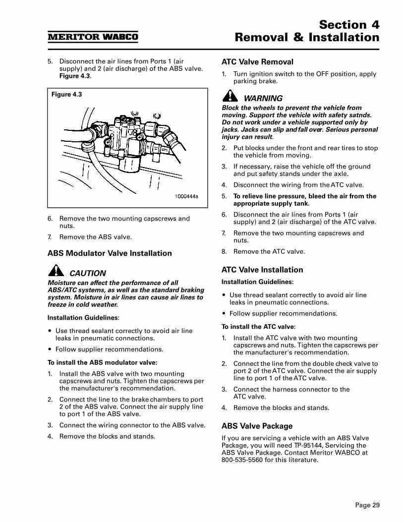
5. Disconnect the air lines from Ports 1 (air supply) and 2 (air discharge) of the ABS valve. Figure 4.3.
6. Remove the two mounting capscrews and nuts.
7. Remove the ABS valve.
ABS Modulator Valve Installation
CAUTIONMoisture can affect the performance of all ABS/ATC systems, as well as the standard braking system. Moisture in air lines can cause air lines to freeze in cold weather.
Installation Guidelines:
O Use thread sealant correctly to avoid air line leaks in pneumatic connections.
O Follow supplier recommendations.
To install the ABS modulator valve:
1. Install the ABS valve with two mounting capscrews and nuts. Tighten the capscrews per the manufacturer's recommendation.
2. Connect the line to the brake chambers to port 2 of the ABS valve. Connect the air supply line to port 1 of the ABS valve.
3. Connect the wiring connector to the ABS valve.
4. Remove the blocks and stands.
ATC Valve Removal
1. Turn ignition switch to the OFF position, apply parking brake.
WARNINGBlock the wheels to prevent the vehicle from moving. Support the vehicle with safety satnds. Do not work under a vehicle supported only by jacks. Jacks can slip and fall over. Serious personal injury can result.
2. Put blocks under the front and rear tires to stop the vehicle from moving.
3. If necessary, raise the vehicle off the ground and put safety stands under the axle.
4. Disconnect the wiring from the ATC valve.
5. To relieve line pressure, bleed the air from the appropriate supply tank.
6. Disconnect the air lines from Ports 1 (air supply) and 2 (air discharge) of the ATC valve.
7. Remove the two mounting capscrews and nuts.
8. Remove the ATC valve.
ATC Valve Installation
Installation Guidelines:
O Use thread sealant correctly to avoid air line leaks in pneumatic connections.
O Follow supplier recommendations.
To install the ATC valve:
1. Install the ATC valve with two mounting capscrews and nuts. Tighten the capscrews per the manufacturer's recommendation.
2. Connect the line from the double check valve to port 2 of the ATC valve. Connect the air supply line to port 1 of the ATC valve.
3. Connect the harness connector to the ATC valve.
4. Remove the blocks and stands.
ABS Valve Package
If you are servicing a vehicle with an ABS Valve Package, you will need TP-95144, Servicing the ABS Valve Package. Contact Meritor WABCO at 800-535-5560 for this literature.
Figure 4.3
Section 5Wiring
Page 30
Section 5Wiring
Wiring
This section contains ABS wiring diagrams and connector pin callouts. If you have any questions, please contact Meritor Customer Service at 800-535-5560.
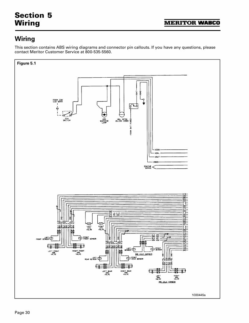
Figure 5.1
Page 31
Section 5Wiring
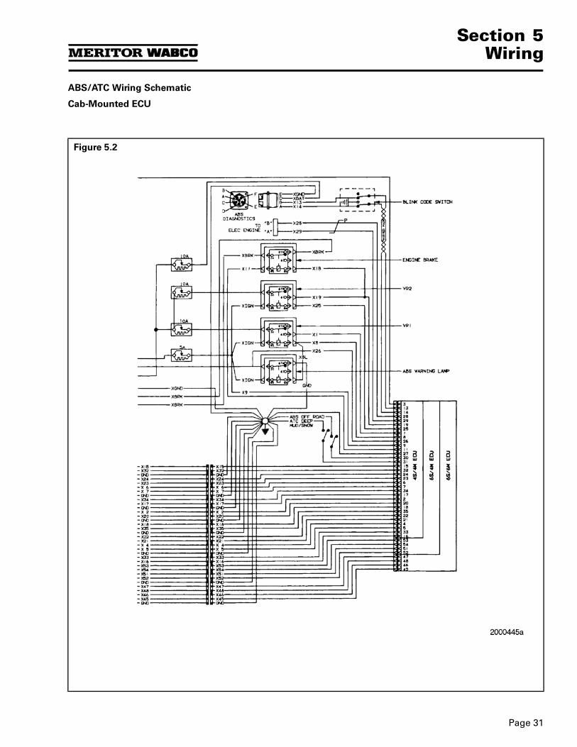
ABS/ATC Wiring Schematic
Cab-Mounted ECU
Figure 5.2
Section 5Wiring
Page 32
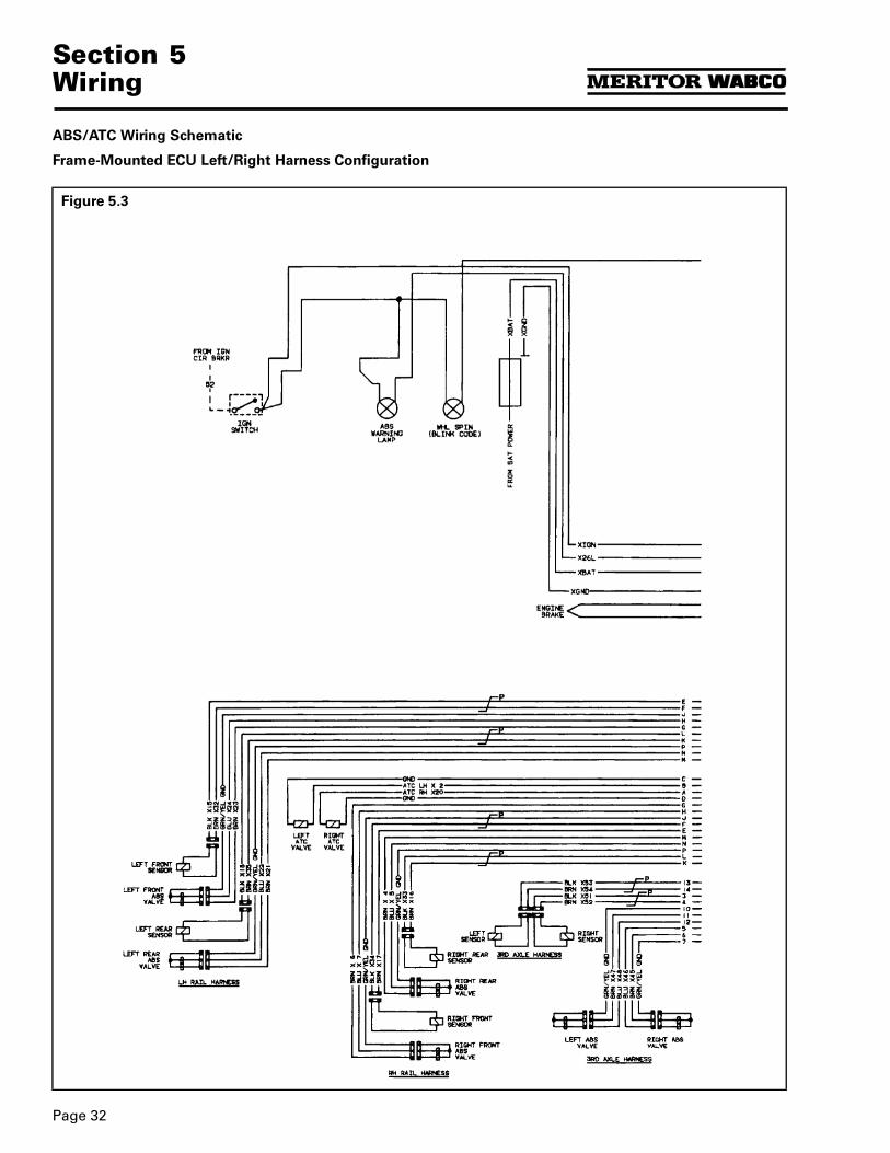
ABS/ATC Wiring Schematic
Frame-Mounted ECU Left/Right Harness Configuration
Figure 5.3
Page 33
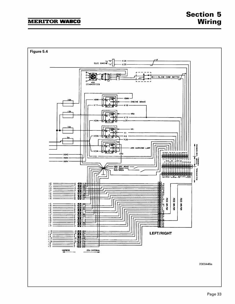
Section 5Wiring
Figure 5.4
Section 5Wiring
Page 34
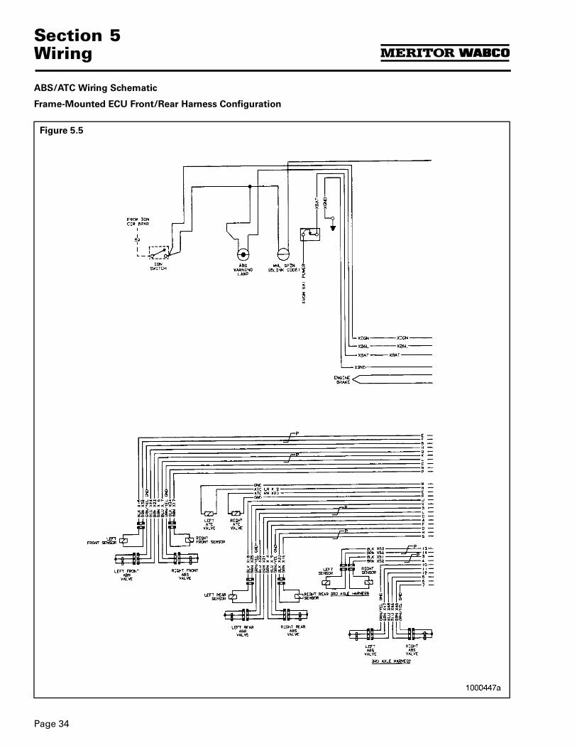
ABS/ATC Wiring Schematic
Frame-Mounted ECU Front/Rear Harness Configuration
Figure 5.5
Page 35
Section 5Wiring
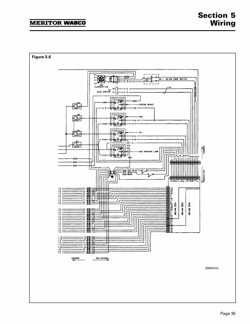
Figure 5.6
Section 5Wiring
Page 36
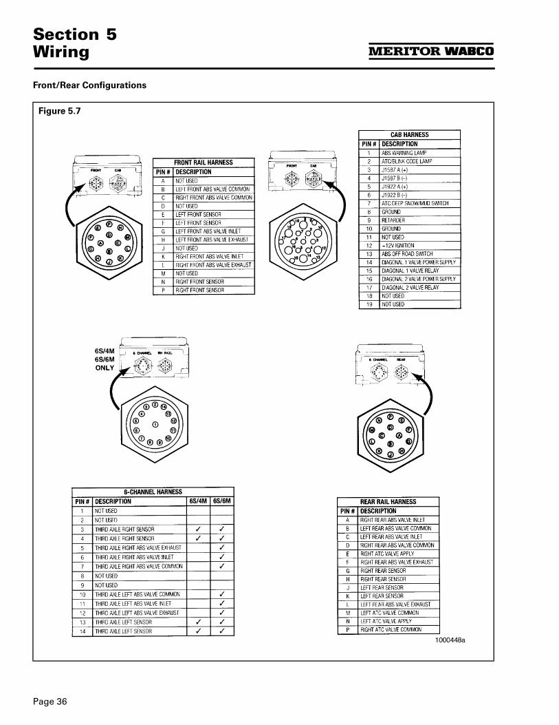
Front/Rear Configurations
Figure 5.7
Page 37
Section 5Wiring
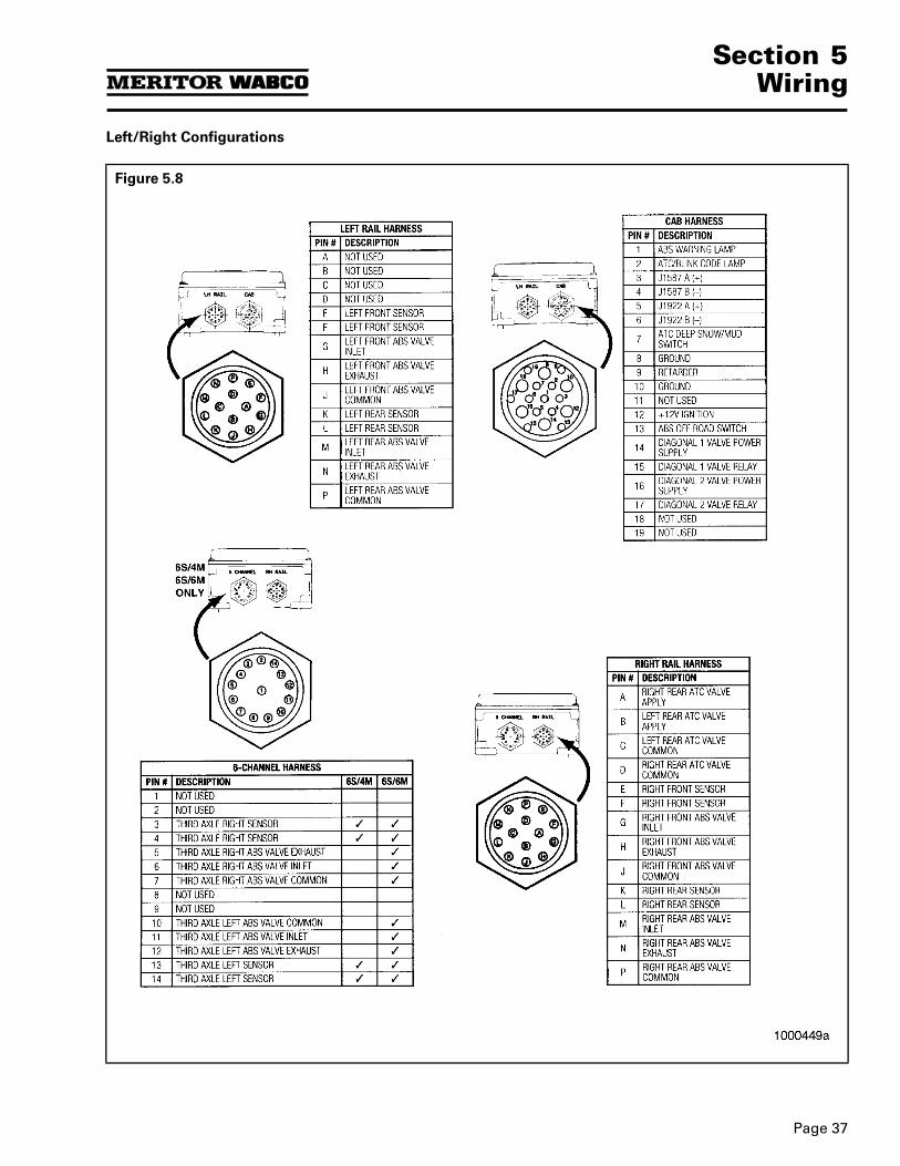
Left/Right Configurations
Figure 5.8
Section 5Wiring
Page 38
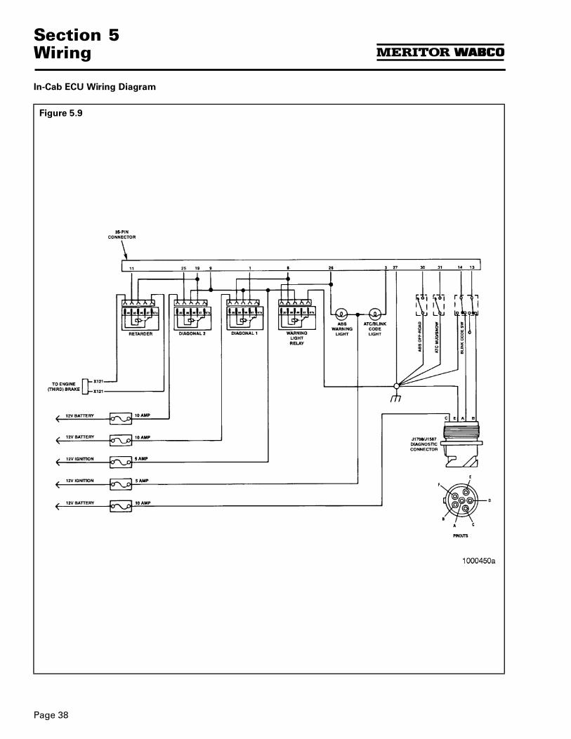
In-Cab ECU Wiring Diagram
Figure 5.9
Page 39
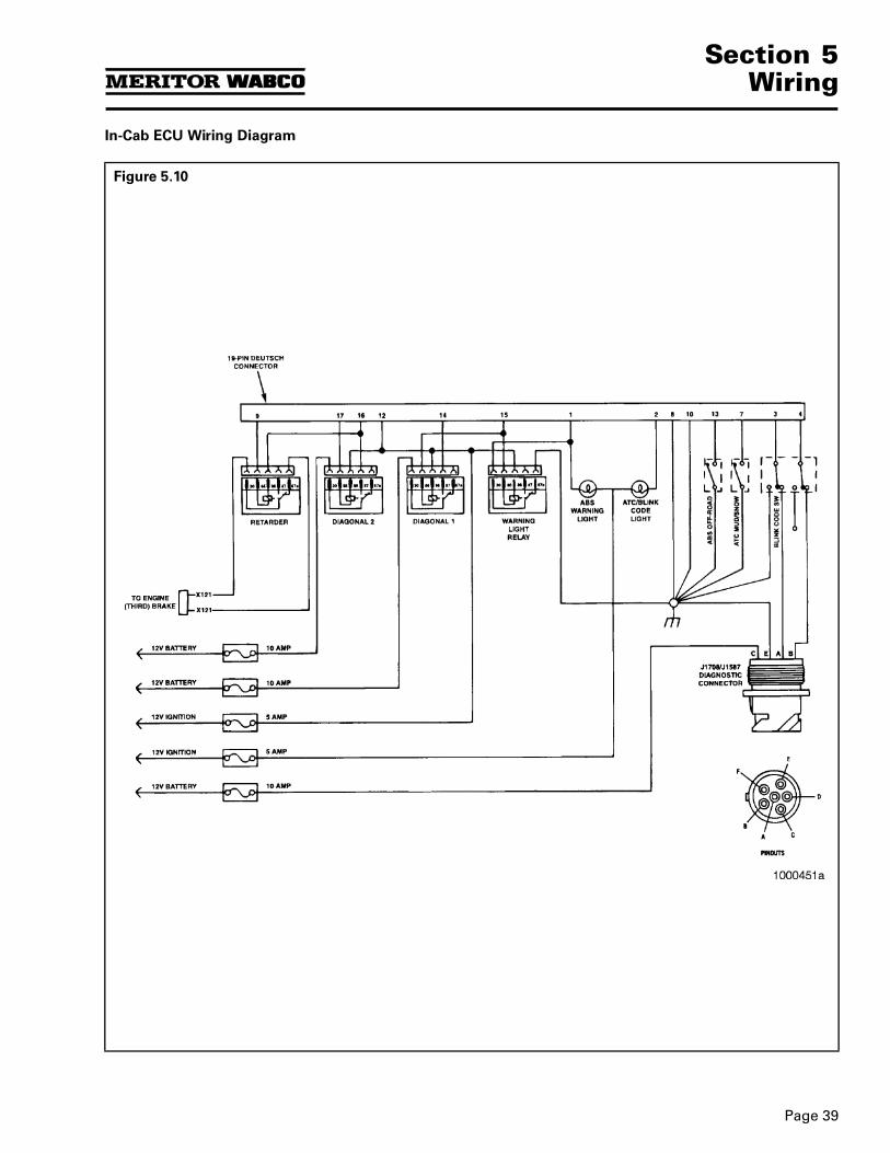
Section 5Wiring
In-Cab ECU Wiring Diagram
Figure 5.10
Information contained in this publication was in effect at the time the publication was approved for printing and is subject to change without notice or liability. Meritor WABCO reserves the right torevise the information presented or discontinue the production of parts described at any time.
© Copyright Maintenance Manual No. 28Meritor WABCO Printed in the USA Revised 4/98All Rights Reserved Please Recycle
Meritor WABCOVehicle Control Systems2135 West Maple RoadTroy, MI 48084 U.S.A.800-535-5560www.meritorauto.com
1998
16579/Meritor


![5.2 - ABS Braking System [OCR]](https://static.fdocuments.in/doc/165x107/577cc3b21a28aba71196e345/52-abs-braking-system-ocr.jpg)